US7654954B1 - Surgical retractor clamp connectable to an arm of the retractor - Google Patents
Surgical retractor clamp connectable to an arm of the retractorDownload PDFInfo
- Publication number
- US7654954B1 US7654954B1US10/613,646US61364603AUS7654954B1US 7654954 B1US7654954 B1US 7654954B1US 61364603 AUS61364603 AUS 61364603AUS 7654954 B1US7654954 B1US 7654954B1
- Authority
- US
- United States
- Prior art keywords
- retractor
- arm
- clamp
- arms
- rack
- Prior art date
- Legal status (The legal status is an assumption and is not a legal conclusion. Google has not performed a legal analysis and makes no representation as to the accuracy of the status listed.)
- Expired - Lifetime, expires
Links
- 230000008859changeEffects0.000claimsdescription3
- 238000001356surgical procedureMethods0.000description10
- 238000000034methodMethods0.000description8
- 210000002414legAnatomy0.000description7
- 230000008901benefitEffects0.000description2
- 238000002324minimally invasive surgeryMethods0.000description2
- 238000011084recoveryMethods0.000description2
- 210000000689upper legAnatomy0.000description2
- 238000010276constructionMethods0.000description1
- 230000003247decreasing effectEffects0.000description1
- 230000001419dependent effectEffects0.000description1
- 230000000994depressogenic effectEffects0.000description1
- 230000006872improvementEffects0.000description1
- 230000007246mechanismEffects0.000description1
- 238000012986modificationMethods0.000description1
- 230000004048modificationEffects0.000description1
- 210000002784stomachAnatomy0.000description1
- 230000003245working effectEffects0.000description1
Images


Classifications
- A—HUMAN NECESSITIES
- A61—MEDICAL OR VETERINARY SCIENCE; HYGIENE
- A61B—DIAGNOSIS; SURGERY; IDENTIFICATION
- A61B17/00—Surgical instruments, devices or methods
- A61B17/02—Surgical instruments, devices or methods for holding wounds open, e.g. retractors; Tractors
- A61B17/0206—Surgical instruments, devices or methods for holding wounds open, e.g. retractors; Tractors with antagonistic arms as supports for retractor elements
Definitions
- the method and devices disclosedare related to procedures and products utilized in minimally invasive joint surgery, and more particularly to retractors and associated components which are utilized in minimally invasive hip surgery.
- hip surgeryis an invasive procedure. Surgeons usually make large incisions and dislocate the femur at the hip. The femur is then placed across the patient's stomach while the surgeon accesses the hip area.
- a retractor assemblyincludes a retractor frame having two arms extending from a rack.
- the two armsmay be curved, straight, or angled.
- the armsmay also be hinged. At least one, and possibly both of the arms are locatable relative to the rack.
- the rackmay be curved such as to define an arc of a circle, or having a changing radius such as a segment of a french curve.
- Retractor clampsare utilized with the frame and may be connected to either the arms or the rack itself. Some retractor clamps are adapted to fit slide into position and need not necessarily have any other connecting mechanism to secure the clamp to the arm or rack. Other clamps have a retaining clip which may be spring biased to hold the clamp in a desired location on the arm or rack. Some clamps maintain a mount in a fixed position. Other clamps have mounts which are pivotable relative to their connection on the arm or rack. The rack or other portion of the system may then be connected to a bed rail or vertical post connected to the operating table or other fixture to fixedly secure the position of the retractor system components. The pivoting feature allows the mount to lift or push retractor blades into or out of an incision. The retractor clamps may be connected to a retractor handle and then to a blade. When the tissue is retracted to a desired position, the clamp is then secured to an arm or rack. The handle may then be disconnected from the blade.
- an extension armis illustrated connected to an arm.
- the extension armallows for substantially three hundred and sixty degrees of capability of positioning retractor clamps about an incision.
- FIG. 1is a top plan view of a retractor frame of a presently preferred embodiment of the present invention
- FIG. 2is a top plan view of a first alternatively preferred embodiment of the retractor frame of the present invention
- FIG. 3 ais a top plan view of a second alternatively preferred embodiment of the retractor frame of the present invention with two retractor clamps connected thereto;
- FIG. 3 bis a back side plan view of the rack used in the retractor frame of FIG. 3 a;
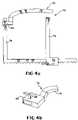
- FIG. 4 ais a top plan view of a third alternatively preferred embodiment of the retractor frame of the present invention with an extension arm connected thereto;
- FIG. 4 ais a side perspective view of the extension arm shown in FIG. 4 a;
- FIG. 5is top plan view of a fourth alternatively preferred embodiment of the retractor frame of the present invention.
- FIG. 6is a side plan view of an arm of the fourth alternatively preferred embodiment in an unlocked position
- FIG. 7is a side plan view of a preferred retractor clamp of the present invention.
- FIG. 8is a side plan view of the retractor clamp of FIG. 7 with the mount pivoted downwardly;
- FIG. 9is a side plan view of the retractor clamp of FIG. 7 with the mount pivoted upwardly;
- FIG. 10is a top plan view of the retractor clamp of FIG. 7 .
- FIG. 11is a side plan view of a first alternatively preferred retractor clamp of the present invention.
- FIG. 12is a side plan view of a second alternatively preferred retractor clamp of the present invention.
- FIG. 13is a top plan view of the retractor clamp of FIG. 12 ;
- FIG. 14is a side plan view of a retractor blade for use in the present invention.
- FIG. 15is a top plan view of the retractor blade end shown in FIG. 14 .
- FIG. 16is top plan view of an alternatively preferred retractor blade end.
- FIG. 17is a side plan view of the retractor blade end of FIG. 16 ;
- FIG. 18is a side plan view of a handle for use with the retractor blades of FIGS. 15-17 .
- FIG. 19is a perspective view of a surgical retractor system in use.
- FIGS. 1-17show a plurality of embodiments of the devices used with minimally invasive joint surgery.
- FIG. 1shows a retractor frame 10 having a curved rack 12 or cross member.
- Racks of traditional framesare not believed to have been curved structures, however the curved rack 12 has been found helpful in applications such as joint surgery since the distal portion 14 of the rack 12 is further from the first arm 18 than the proximal portion 16 .
- the distal portion 14will be out of the surgeon's way so that he or she can access the incision between the arms 18 , 20 .
- Another feature believed to be novelis the provision of two adjustment housings 22 , 24 which are slidably mounted relative to the rack 12 with each housing 22 , 24 respectively connected to the arms 18 , 20 . This feature is believed to be helpful so that the rack 12 which is not intermediate the housings 22 , 24 may be positioned so that is opposite the surgeon, or otherwise located out of the way.
- frame 30is illustrated with rack 32 having a first and second arcs 34 , 36 which would have two different radii.
- the radiicould be continuously changing such as provided by a french curve and/or include more distinct radii sections. This may assist in providing a desired angular relationship between the arms 38 , 40 for some surgical procedures at a desired spacing.
- the arms 18 , 20 and 38 , 40are not parallel. While the arms 18 , 20 and 38 , 40 could be parallel in some embodiments, such as shown in FIG. 4 , the non-parallel nature of these arms is believed to be new to the art when straight arms are utilized. Additionally, as shown in FIG. 2 , the angular relationship between the arms 38 , 40 can be varied based on where on the rack 32 the arms 38 , 40 are positioned, especially if each arm 38 , 40 has a housing 42 connected thereto to allow movement of the both arms 38 , 40 relative to the rack 32 . As can be seen in FIG. 1 , the angle between first and second axes 26 , 28 is about 15 degrees. Depending on the spacing between the housing for a fixed radius arc segment of rack 12 , the angle will vary with the spacing.
- the angle between first and second axes 44 , 46is not solely dependent upon spacing between the arms 38 , 40 . While the three axes 44 , 46 , 48 are substantially equally spaced from one another where they intersect the rack 32 , the angle between the first and second axes 44 , 46 while the angle between the second and third axes 46 , 48 is about forty five degrees. In other embodiments, the radii of arc segments may be different which of course would affect the angular relationship of the arms 38 , 40 as the spacing between the arms is increased or decreased.
- housingsmay be designed or provided that allow for the arms 38 , 40 to be maintained parallel to the rack 32 through the changes in radii or for a specific radii by providing a connection of the arms at the housing allowing rotational movement of the arm relative to the housing or otherwise.
- FIG. 3 ashows an alternatively preferred embodiment of the preferred invention which shows some of the versatility of the retractor system described herein.
- Retractor 50has a fixed arm 52 and a moveable arm 54 . Unlike the hinged and straight arms shown in FIGS. 1 and 2 , the arms 52 , 54 are curved along their length. This structure is believed to assist for certain shaped incisions. The rate of curvature may vary along the length, however the embodiment shown shows a relatively constant rate of curvature.
- the rack 56may be substantially linear as illustrated, or could be curved as shown in FIGS. 1 , 2 and 3 b .
- the arms 52 , 54 as well as the rack 56may be provided with retractor clamps 58 , 60 .
- the clampsare shown on the first arm 52 , they may also be placed on the second arm 54 or the rack 56 .
- the arms 52 , 54may either have a smooth back 62 , or a scalloped back 64 depending upon the needs of the user and the particular components to be utilized with the retractor frame 50 .
- some racks 56can be dome shaped or curved as shown in FIG. 3 b as well as curved as shown in FIGS. 1 and 2 so that they are curved in more than two dimensions. The “doming” of the rack 56 has been found helpful in getting the ends 57 , 59 out of a surgeon's way in some procedures.
- FIGS. 4 a and 4 bhas been provided to illustrate a particular accessory for use with retractor frames, such as with a traditional frame 70 or any of the improved frames shown in FIGS. 1 - 3 or others.
- the extension arm 72is believed to be a new development in the field of components utilized with retractor frames 70 .
- the extension arm 72may provide a surgeon the ability to provide substantially 360 degree coverage about an incision for locations to place a retractor clamp, and thus direct a retractor into an incision. This flexibility provides the surgeon with numerous options to provide a retracted incision while minimizing any impediments to his vision or ability to work within the incision.
- the extension arm 72may be substantially planar with the arms or it may elevate a support surface 74 above the arm, illustrated as first arm 76 it is connected so that the support surface 74 may pass over, or under, the second arm, such as second arm 78 .
- the extension arm 72may be connected to the second arm 78 instead of the first arm 76 as illustrated.
- the extension arm 72may be equipped with a housing 80 which may either secure the extension arm 72 to an arm 76 , 78 or it may be somewhat similarly constructed as the housing 82 on either the first or second arms 76 , 78 to allow the surgeon or assistant to retract tissue away from the rack 84 .
- extension 74is illustrated as having a curved and/or domed support surface 74 , however it could be straight, angled or otherwise constructed such as in a manner illustrated for the racks and arms shown herein.
- the use of the extension arm 74is believed to be a huge improvement over the technique shown in U.S. Pat. No. 5,795,291, incorporated by reference, which requires using two retractor frames.
- the system utilizedmay be secured to a fixed support such as a vertical post 300 , a rail of an operating table or other appropriate location as shown in FIG. 19 .
- FIGS. 5 and 6show other features which may be incorporated into retractor frame construction for minimally invasive joint surgery.
- Frame 90is illustrated having a rack 92 with arms 94 , 96 connected thereto. Housings 98 , 100 allow either of the arms 94 , 96 to be moved relative to the rack 92 .
- the arms 94 , 96have intermediate segments 102 , 104 which are angled relative to first and second end segments 106 , 108 and 110 , 112 , respectively.
- the first and second end segments 106 , 110 and 108 , 112are parallel to one another, respectively.
- the geometry of the arms 94 , 96can be seen as being substantially rectangular except where the first segment 110 connects with housing 100 .
- the first segment 110is substantially round at base 114 .
- the base 114has serrated surface 116 which cooperates with serrated surface 118 on housing 100 .
- Locking lever 120locks and unlocks the first segment 110 relative to the housing 100 .
- the first segment 110is illustrated as being rotatable relative to the housing 100 so that retractors may be positioned down into a wound or elevated relative to the wound when the first segment is in an unlocked configuration as shown in FIG. 6 .
- This featureis also believed to be useful with racks which are dome shaped as shown in FIG. 3 b to provide a desired angle of the arms relative to the rack (for instance, the planes the arms are in may be made to be parallel to one another even though the rack is not linear in some embodiments).
- the serrated surfaces 116 , 118are brought into contact with one another to fix the rotational position of the arm 110 relative to the housing 110 .
- the lever 120is operably connected to a cam (obscured from view) within the first segment 110 which cooperates with post 122 to move the first segment 110 relative to the housing 110 .
- a camobscured from view
- first segment 110or a portion of the first segment 110 may be rotatably positioned relative to axis 124 and then secured at a desired position.
- the first arm 94is illustrated as having a similar angular adjustment feature as the second arm 96 which has been described in detail above. While this embodiment has hinged arms defined by segments 106 , 102 , 108 and 110 , 104 , 112 , the arms of FIGS. 1-4 could also be provided with this capability.
- the interior workings of the housing 100are also illustrated in FIG. 6 . While other devices are known in the art, the housing 100 has a driver 126 actuated by a handle 128 .
- the driver 126 illustratedis a wheel with spokes 130 adapted to fit within slots 132 shown in FIG. 5 .
- Release lever 134may act allow the driver 126 to act as a ratchet to move in only one direction when in the normally biased position illustrated, or it may be depressed to disengage the driver 126 from the slots 132 to allow the arm 96 to be positioned at the will of the user of the rack 92 .
- FIG. 7shows a side plan view of a clamp 140 which has a release button 142 for removing the clamp 140 once installed as shown in FIG. 3 .
- the buttonacts on latch 144 about pivot 146 .
- the latch 144is normally biased by spring 148 into engagement with a back side 62 of an arm 52 . While clamps have only been shown in FIG. 3 , the same clamps could be utilized with any of the embodiments illustrated on any of the arms or racks.
- the clamp 140has a slot 150 which receives an arm or a rack therein.
- the latch 144retains the inserted frame part.
- the slot 150is illustrated as defined between upper and lower surfaces 152 , 154 .
- the upper and lower surfaces 152 , 154are illustrated as parallel to one another.
- the clamphas a mount 156 which connects to the member 158 containing the slot 150 .
- the mount 156 of this embodimentis moveable relative to the member 158 . This feature is not provided in the clamps shown in FIGS. 11-13 .
- the mount 156is connected to or more preferably apart of leg 160 .
- Leg 160is operably coupled to the member 158 by pivot 162 .
- FIG. 7shows the leg 160 substantially parallel to the slot 150 .
- operator 164is utilized in order to change the angle of the leg 160 relative to the slot 150 .
- threads at distal end 166pass through nut 168 which is then moved along the axis of rotation of the operator 164 .
- the nut 168moves, it acts against projections 170 , 172 to either pivot the leg downwardly as shown in FIG. 8 , or upwardly as shown in FIG. 9 .
- there are cutout portions in the projections 170 , 172 and leg 160which receive the distal end 166 of the operator 164 to allow for this positioning.
- a quick release button 174can be pushed which disengages threaded gear 176 to release the operator 164 . Releasing the button 174 re-engages the gear 176 with the operator 164 to allow for continued adjustment with the operator 164 .
- FIG. 10shows a top plan view of the clamp 140 .
- Groove 178provides access to the mount from a hand held gripper which is illustrated in FIG. 18 .
- the headmay extend up into the mount 156 where it is held by the hand held gripper and then the retractor is pulled or pushed into a desired location where the clamp may then be connected to an arm or rack and the hand held gripper may then release the clamp.
- FIG. 11shows an alternatively preferred embodiment of a clamp 180 which lacks the pivotal capability of the mount 182 and leg 184 relative to the slot 186 .
- the clamps 140 and 180are very similar.
- the top view of the clamp 180will be very similar to that shown in FIG. 10 without the operator 164 extending as shown.
- FIG. 12shows another clamp 190 which slides onto an end of an arm or rack of a frame.
- the top view of the retractor clamp 190 of FIG. 12is shown in FIG. 13 .
- This clampmay either remain moveable along the arm or rack or may be outfitted with a connector such as shown on the extension arm in FIG. 4 a or otherwise to secure the clamp 190 at a desired location relative to an arm or rack.
- FIG. 14shows a retractor blade 200 which has a head 202 and a contact surface 204 .
- the contact surface 204is illustrated as a “Hohmann” contact surface which is shown in detail in FIG. 15
- FIGS. 16-17show a “Hayes” contact surface.
- the head 202may take on a number of shapes and is adapted to work with the selected mount of the clamp which will be utilized to retain the retractor blade.
- FIG. 18shows a hand held gripper 210 .
- the gripper 210has a handle 212 which twists relative to a shoe 214 .
- a post 218extends into a bore in the shoe 214 and onto a top of a head 202 of an inserted retractor blade 200 to secure the blade relative to the gripper 210 .
- the head 202has previously been inserted into slot 216 in the gripper 210 .
- the handle 212is twisted in an opposite direction and the head 202 is released by the post 218 .
- the head 202may then be slid out of slot 216 .
Landscapes
- Health & Medical Sciences (AREA)
- Life Sciences & Earth Sciences (AREA)
- Surgery (AREA)
- Heart & Thoracic Surgery (AREA)
- Engineering & Computer Science (AREA)
- Biomedical Technology (AREA)
- Nuclear Medicine, Radiotherapy & Molecular Imaging (AREA)
- Medical Informatics (AREA)
- Molecular Biology (AREA)
- Animal Behavior & Ethology (AREA)
- General Health & Medical Sciences (AREA)
- Public Health (AREA)
- Veterinary Medicine (AREA)
- Surgical Instruments (AREA)
Abstract
Description
This application claims the benefit of U.S. Provisional Patent Application No. 60/394,342 filed Jul. 3, 2002.
The method and devices disclosed are related to procedures and products utilized in minimally invasive joint surgery, and more particularly to retractors and associated components which are utilized in minimally invasive hip surgery.
Traditionally, hip surgery is an invasive procedure. Surgeons usually make large incisions and dislocate the femur at the hip. The femur is then placed across the patient's stomach while the surgeon accesses the hip area.
In order to shorten the recovery times, minimally invasive surgery has been proposed so that recovery times can be shortened which reduces the total costs of the procedure. In order to perform minimally invasive surgery on joints, such as the hip, new procedures and devices are necessary.
A need exists for a retractor support apparatus and associated components as well as a method for their use in minimally invasive joint surgery, including hip surgery.
A need also exists for the use of a retractor assembly and associated components for use in minimally invasive joint surgery.
Another need exists for an improved retractor.
Another need exists for an improved retractor clamp.
Yet another need exists for an improved retractor frame.
Accordingly a retractor assembly includes a retractor frame having two arms extending from a rack. The two arms may be curved, straight, or angled. The arms may also be hinged. At least one, and possibly both of the arms are locatable relative to the rack. Instead of being straight as has been traditionally done, the rack may be curved such as to define an arc of a circle, or having a changing radius such as a segment of a french curve.
Retractor clamps are utilized with the frame and may be connected to either the arms or the rack itself. Some retractor clamps are adapted to fit slide into position and need not necessarily have any other connecting mechanism to secure the clamp to the arm or rack. Other clamps have a retaining clip which may be spring biased to hold the clamp in a desired location on the arm or rack. Some clamps maintain a mount in a fixed position. Other clamps have mounts which are pivotable relative to their connection on the arm or rack. The rack or other portion of the system may then be connected to a bed rail or vertical post connected to the operating table or other fixture to fixedly secure the position of the retractor system components. The pivoting feature allows the mount to lift or push retractor blades into or out of an incision. The retractor clamps may be connected to a retractor handle and then to a blade. When the tissue is retracted to a desired position, the clamp is then secured to an arm or rack. The handle may then be disconnected from the blade.
Additionally, an extension arm is illustrated connected to an arm. The extension arm allows for substantially three hundred and sixty degrees of capability of positioning retractor clamps about an incision.
The particular features and advantages of the invention as well as other objects will become apparent from the following description taken in connection with the accompanying drawings in which:
Accordingly,FIGS. 1-17 show a plurality of embodiments of the devices used with minimally invasive joint surgery.FIG. 1 shows aretractor frame 10 having acurved rack 12 or cross member. Racks of traditional frames are not believed to have been curved structures, however thecurved rack 12 has been found helpful in applications such as joint surgery since thedistal portion 14 of therack 12 is further from thefirst arm 18 than theproximal portion 16. In a properly designedframe 10, thedistal portion 14 will be out of the surgeon's way so that he or she can access the incision between thearms
Another feature believed to be novel is the provision of twoadjustment housings rack 12 with eachhousing arms rack 12 which is not intermediate thehousings
InFIG. 2 ,frame 30 is illustrated withrack 32 having a first andsecond arcs arms
As can be seen by examiningFIGS. 1 and 2 , thearms arms FIG. 4 , the non-parallel nature of these arms is believed to be new to the art when straight arms are utilized. Additionally, as shown inFIG. 2 , the angular relationship between thearms rack 32 thearms arm housing 42 connected thereto to allow movement of the botharms rack 32. As can be seen inFIG. 1 , the angle between first andsecond axes rack 12, the angle will vary with the spacing.
InFIG. 2 , since the rack has multiple radii arc segments, the angle between first andsecond axes arms axes rack 32, the angle between the first andsecond axes third axes arms
Of course, housings may be designed or provided that allow for thearms rack 32 through the changes in radii or for a specific radii by providing a connection of the arms at the housing allowing rotational movement of the arm relative to the housing or otherwise.
Depending on the needs of the surgeon, theextension arm 72 may be substantially planar with the arms or it may elevate asupport surface 74 above the arm, illustrated asfirst arm 76 it is connected so that thesupport surface 74 may pass over, or under, the second arm, such assecond arm 78. Of course theextension arm 72 may be connected to thesecond arm 78 instead of thefirst arm 76 as illustrated. Additionally, theextension arm 72 may be equipped with ahousing 80 which may either secure theextension arm 72 to anarm housing 82 on either the first orsecond arms rack 84. Additionally, theextension 74 is illustrated as having a curved and/ordomed support surface 74, however it could be straight, angled or otherwise constructed such as in a manner illustrated for the racks and arms shown herein. The use of theextension arm 74 is believed to be a huge improvement over the technique shown in U.S. Pat. No. 5,795,291, incorporated by reference, which requires using two retractor frames. Furthermore, the system utilized may be secured to a fixed support such as avertical post 300, a rail of an operating table or other appropriate location as shown inFIG. 19 .
FromFIG. 6 , the geometry of thearms first segment 110 connects withhousing 100. Although other geometrical arrangements can be utilized, in the embodiment shown inFIGS. 5 and 6 , thefirst segment 110 is substantially round atbase 114. Thebase 114 hasserrated surface 116 which cooperates withserrated surface 118 onhousing 100. Lockinglever 120 locks and unlocks thefirst segment 110 relative to thehousing 100.
Thefirst segment 110 is illustrated as being rotatable relative to thehousing 100 so that retractors may be positioned down into a wound or elevated relative to the wound when the first segment is in an unlocked configuration as shown inFIG. 6 . This feature is also believed to be useful with racks which are dome shaped as shown inFIG. 3 bto provide a desired angle of the arms relative to the rack (for instance, the planes the arms are in may be made to be parallel to one another even though the rack is not linear in some embodiments). By locking thefirst segment 110, theserrated surfaces arm 110 relative to thehousing 110. Thelever 120 is operably connected to a cam (obscured from view) within thefirst segment 110 which cooperates withpost 122 to move thefirst segment 110 relative to thehousing 110. Of course, there are other ways known in the art wherein thefirst segment 110, or a portion of thefirst segment 110 may be rotatably positioned relative toaxis 124 and then secured at a desired position.
Thefirst arm 94 is illustrated as having a similar angular adjustment feature as thesecond arm 96 which has been described in detail above. While this embodiment has hinged arms defined bysegments FIGS. 1-4 could also be provided with this capability.
The interior workings of thehousing 100 are also illustrated inFIG. 6 . While other devices are known in the art, thehousing 100 has adriver 126 actuated by ahandle 128. Thedriver 126 illustrated is a wheel withspokes 130 adapted to fit withinslots 132 shown inFIG. 5 .Release lever 134 may act allow thedriver 126 to act as a ratchet to move in only one direction when in the normally biased position illustrated, or it may be depressed to disengage thedriver 126 from theslots 132 to allow thearm 96 to be positioned at the will of the user of therack 92.
Referring back toFIG. 3 , twoclamps FIGS. 7-13 .FIG. 7 shows a side plan view of aclamp 140 which has arelease button 142 for removing theclamp 140 once installed as shown inFIG. 3 . The button acts onlatch 144 aboutpivot 146. Thelatch 144 is normally biased byspring 148 into engagement with aback side 62 of anarm 52. While clamps have only been shown inFIG. 3 , the same clamps could be utilized with any of the embodiments illustrated on any of the arms or racks.
Theclamp 140 has aslot 150 which receives an arm or a rack therein. Thelatch 144 retains the inserted frame part. Theslot 150 is illustrated as defined between upper andlower surfaces lower surfaces mount 156 which connects to themember 158 containing theslot 150. Themount 156 of this embodiment is moveable relative to themember 158. This feature is not provided in the clamps shown inFIGS. 11-13 .
In theclamp 140 ofFIGS. 7-10 , themount 156 is connected to or more preferably apart ofleg 160.Leg 160 is operably coupled to themember 158 bypivot 162.FIG. 7 shows theleg 160 substantially parallel to theslot 150. In order to change the angle of theleg 160 relative to theslot 150,operator 164 is utilized. By twisting onoperator 164, threads atdistal end 166 pass throughnut 168 which is then moved along the axis of rotation of theoperator 164. As thenut 168 moves, it acts againstprojections FIG. 8 , or upwardly as shown inFIG. 9 . Of course, there are cutout portions in theprojections leg 160 which receive thedistal end 166 of theoperator 164 to allow for this positioning.
Should a user desire to rapidly change the angle of themount 156 relative to theslot 150, aquick release button 174 can be pushed which disengages threadedgear 176 to release theoperator 164. Releasing thebutton 174 re-engages thegear 176 with theoperator 164 to allow for continued adjustment with theoperator 164.
Numerous alternations of the structure herein disclosed will suggest themselves to those skilled in the art. However, it is to be understood that the present disclosure relates to the preferred embodiment of the invention which is for purposes of illustration only and not to be construed as a limitation of the invention. All such modifications which do not depart from the spirit of the invention are intended to be included within the scope of the appended claims.
Having thus set forth the nature of the invention, what is claimed herein is:
Claims (2)
1. A surgical retractor having a clamp operably connected to at least one arm of the surgical retractor, the clamp comprising:
a member having a slot defined by an upper surface and a lower surface, the slot being substantially parallel to a mount for receiving a portion of the arm, the member having a latch for selectively retaining the clamp at a selected position;
a release button adapted to disengage the latch to release the arm from the slot;
a leg pivotally connected to the member and extending cantilevered away from the slot at a proximate end of the member, the leg having a retractor blade connector head mount for receiving a connector head of a retractor blade, the leg having a first projection and a second projection; and,
an operator for adjusting the angular position of the leg, the operator having a threaded shaft, the threaded shaft having a nut thereon, the nut located between the first and second projection, the nut moveable along an axis of the shaft upon rotation of the shaft, the axial movement of the nut against at least one projection rotates the leg about a pivot.
2. The surgical retractor ofclaim 1 , further comprising a quick release button operably connected to the operator, the quick release button adapted to rapidly change the angle of the mount relative to the slot by disengaging the operator from the threaded shaft.
Priority Applications (1)
| Application Number | Priority Date | Filing Date | Title |
|---|---|---|---|
| US10/613,646US7654954B1 (en) | 2002-07-03 | 2003-07-02 | Surgical retractor clamp connectable to an arm of the retractor |
Applications Claiming Priority (2)
| Application Number | Priority Date | Filing Date | Title |
|---|---|---|---|
| US39434202P | 2002-07-03 | 2002-07-03 | |
| US10/613,646US7654954B1 (en) | 2002-07-03 | 2003-07-02 | Surgical retractor clamp connectable to an arm of the retractor |
Publications (1)
| Publication Number | Publication Date |
|---|---|
| US7654954B1true US7654954B1 (en) | 2010-02-02 |
Family
ID=41581274
Family Applications (1)
| Application Number | Title | Priority Date | Filing Date |
|---|---|---|---|
| US10/613,646Expired - LifetimeUS7654954B1 (en) | 2002-07-03 | 2003-07-02 | Surgical retractor clamp connectable to an arm of the retractor |
Country Status (1)
| Country | Link |
|---|---|
| US (1) | US7654954B1 (en) |
Cited By (27)
| Publication number | Priority date | Publication date | Assignee | Title |
|---|---|---|---|---|
| US20070203400A1 (en)* | 2004-09-03 | 2007-08-30 | Santilli Albert N | Surgical Retractor Having Lifting Capability |
| US20100113885A1 (en)* | 2008-10-30 | 2010-05-06 | Warsaw Orthopedic, Inc. | Retractor assemblies for surgery in a patient |
| US20110130793A1 (en)* | 2009-11-10 | 2011-06-02 | Nuvasive Inc. | Method and apparatus for performing spinal surgery |
| US20120316401A1 (en)* | 2010-02-12 | 2012-12-13 | Kenichi Matsumura | Rib spreader |
| US8636655B1 (en) | 2010-01-19 | 2014-01-28 | Ronald Childs | Tissue retraction system and related methods |
| US8900137B1 (en) | 2011-04-26 | 2014-12-02 | Nuvasive, Inc. | Cervical retractor |
| US8974381B1 (en) | 2011-04-26 | 2015-03-10 | Nuvasive, Inc. | Cervical retractor |
| KR20150001215U (en) | 2013-09-12 | 2015-03-20 | 내셔널 타이완 유니버시티 호스피탈 | Device of Automatic Mechanical Wound Opener for Head and Neck Surgery |
| US20150100078A1 (en)* | 2013-10-07 | 2015-04-09 | National Taiwan University Hospital | Device of Automatic Mechanical Wound Opener for Head and Neck Surgery |
| US9113853B1 (en) | 2011-08-31 | 2015-08-25 | Nuvasive, Inc. | Systems and methods for performing spine surgery |
| US9289199B1 (en)* | 2014-01-09 | 2016-03-22 | Neotech Products, Inc. | Retinal examination apparatus |
| US9307972B2 (en) | 2011-05-10 | 2016-04-12 | Nuvasive, Inc. | Method and apparatus for performing spinal fusion surgery |
| US9675389B2 (en) | 2009-12-07 | 2017-06-13 | Samy Abdou | Devices and methods for minimally invasive spinal stabilization and instrumentation |
| US9795370B2 (en) | 2014-08-13 | 2017-10-24 | Nuvasive, Inc. | Minimally disruptive retractor and associated methods for spinal surgery |
| US10245014B2 (en) | 2013-10-07 | 2019-04-02 | National Taiwan University Hospital | Device of automatic mechanical wound opener for head and neck surgery |
| US10548740B1 (en) | 2016-10-25 | 2020-02-04 | Samy Abdou | Devices and methods for vertebral bone realignment |
| US10575961B1 (en) | 2011-09-23 | 2020-03-03 | Samy Abdou | Spinal fixation devices and methods of use |
| US10695105B2 (en) | 2012-08-28 | 2020-06-30 | Samy Abdou | Spinal fixation devices and methods of use |
| US10857003B1 (en) | 2015-10-14 | 2020-12-08 | Samy Abdou | Devices and methods for vertebral stabilization |
| US10918498B2 (en) | 2004-11-24 | 2021-02-16 | Samy Abdou | Devices and methods for inter-vertebral orthopedic device placement |
| US10973648B1 (en) | 2016-10-25 | 2021-04-13 | Samy Abdou | Devices and methods for vertebral bone realignment |
| US11006982B2 (en) | 2012-02-22 | 2021-05-18 | Samy Abdou | Spinous process fixation devices and methods of use |
| US11173040B2 (en) | 2012-10-22 | 2021-11-16 | Cogent Spine, LLC | Devices and methods for spinal stabilization and instrumentation |
| US11179248B2 (en) | 2018-10-02 | 2021-11-23 | Samy Abdou | Devices and methods for spinal implantation |
| US20220039786A1 (en)* | 2020-08-06 | 2022-02-10 | Warsaw Orthopedic, Inc. | Surgical retractor and method |
| US11701097B2 (en) | 2012-07-17 | 2023-07-18 | Warsaw Orthopedic, Inc. | Surgical retractor and method of use |
| US11793504B2 (en) | 2011-08-19 | 2023-10-24 | Nuvasive, Inc. | Surgical retractor system and methods of use |
Citations (28)
| Publication number | Priority date | Publication date | Assignee | Title |
|---|---|---|---|---|
| US1963173A (en)* | 1933-01-03 | 1934-06-19 | Horace Lauzon | Retractor |
| US2751903A (en)* | 1954-04-22 | 1956-06-26 | Harry S Ivory | Adjustable retractor for surgical use |
| US3227156A (en)* | 1962-12-04 | 1966-01-04 | William K Gauthier | Abdominal retractor device |
| US3384077A (en)* | 1965-01-22 | 1968-05-21 | William K. Gauthier | Abdominal retractor device |
| US3384078A (en)* | 1965-11-01 | 1968-05-21 | William K. Gauthier | Adjustable retractor blade |
| US3749088A (en)* | 1971-06-23 | 1973-07-31 | W Kohlmann | Surgical retractor device |
| US3789835A (en)* | 1972-03-16 | 1974-02-05 | R Whitman | Illuminating attachments for vaginal speculum |
| US3965890A (en)* | 1974-10-18 | 1976-06-29 | William Kohlmann Gauthier | Surgical retractor |
| US4424724A (en)* | 1981-10-09 | 1984-01-10 | Codman & Shurtleff, Inc. | Multi-position ratchet mechanism |
| US4726356A (en)* | 1985-11-12 | 1988-02-23 | Kapp Surgical Instrument, Inc. | Cardiovascular and thoracic retractor |
| US5020195A (en)* | 1989-01-27 | 1991-06-04 | Minnesota Scientific, Inc. | Clamping device for use on a retractor support |
| US5171927A (en)* | 1991-03-04 | 1992-12-15 | Collins Kubicki, Inc. | Apparatus and method for tuning and intonating the strings of a bass or treble guitar |
| US5727899A (en)* | 1996-09-13 | 1998-03-17 | Minnesota Scientific, Inc. | Fulcrum clamp |
| US5788630A (en)* | 1996-09-25 | 1998-08-04 | Genzyme Corporation | Rib retractor |
| US5792046A (en)* | 1996-02-22 | 1998-08-11 | Minnesota Scientific, Inc. | Cammed retractor clamp |
| US5888197A (en)* | 1997-07-01 | 1999-03-30 | Thompson Surgical Instruments, Inc. | Cam-operated universal latch joint apparatus |
| US5893831A (en)* | 1998-03-19 | 1999-04-13 | Koros; Tibor B. | Retractor blade locking mechanism |
| US5908382A (en)* | 1998-07-08 | 1999-06-01 | Koros; Tibor B. | Minimally invasive retractor for internal mammary artery harvesting |
| US6234961B1 (en)* | 1998-04-15 | 2001-05-22 | Pineridge Holding Pty. Ltd. | Ball and socket interconnection and retractor assembly employing the same |
| US6241659B1 (en)* | 1999-10-06 | 2001-06-05 | Codman & Shurtleff, Inc. | Surgical retractor assembly with controlled rotation |
| US20010009971A1 (en)* | 1996-04-26 | 2001-07-26 | Sherts Charles R. | Surgical retractor |
| US6277069B1 (en)* | 1998-06-09 | 2001-08-21 | Pine Ridge Holding Pty. Ltd. | Clamping device |
| US6331158B1 (en)* | 1999-05-04 | 2001-12-18 | Cardiothoracic Systems, Inc. | Surgical retractor apparatus for operating on the heart through an incision |
| US6431025B1 (en)* | 1996-08-30 | 2002-08-13 | Tibor Koros | Ratchet mechanism for a surgical retractor assembly |
| US20020177754A1 (en)* | 2001-05-23 | 2002-11-28 | Phillips Burns P. | Retractor clamp assembly |
| US20020177753A1 (en)* | 2001-05-25 | 2002-11-28 | Minnesota Scientific, Inc. | Multi-position spherical retractor holder |
| US20030065251A1 (en)* | 2001-10-02 | 2003-04-03 | David Feng | Multipositional ratchet device for surgical retractor |
| US6620097B1 (en)* | 2002-03-29 | 2003-09-16 | Codman & Shurtleff, Inc. | Three-dimensional tilt ratchet mechanism |
- 2003
- 2003-07-02USUS10/613,646patent/US7654954B1/ennot_activeExpired - Lifetime
Patent Citations (30)
| Publication number | Priority date | Publication date | Assignee | Title |
|---|---|---|---|---|
| US1963173A (en)* | 1933-01-03 | 1934-06-19 | Horace Lauzon | Retractor |
| US2751903A (en)* | 1954-04-22 | 1956-06-26 | Harry S Ivory | Adjustable retractor for surgical use |
| US3227156A (en)* | 1962-12-04 | 1966-01-04 | William K Gauthier | Abdominal retractor device |
| US3384077A (en)* | 1965-01-22 | 1968-05-21 | William K. Gauthier | Abdominal retractor device |
| US3384078A (en)* | 1965-11-01 | 1968-05-21 | William K. Gauthier | Adjustable retractor blade |
| US3749088A (en)* | 1971-06-23 | 1973-07-31 | W Kohlmann | Surgical retractor device |
| US3789835A (en)* | 1972-03-16 | 1974-02-05 | R Whitman | Illuminating attachments for vaginal speculum |
| US3965890A (en)* | 1974-10-18 | 1976-06-29 | William Kohlmann Gauthier | Surgical retractor |
| US4424724A (en)* | 1981-10-09 | 1984-01-10 | Codman & Shurtleff, Inc. | Multi-position ratchet mechanism |
| US4726356A (en)* | 1985-11-12 | 1988-02-23 | Kapp Surgical Instrument, Inc. | Cardiovascular and thoracic retractor |
| US5020195A (en)* | 1989-01-27 | 1991-06-04 | Minnesota Scientific, Inc. | Clamping device for use on a retractor support |
| US5171927A (en)* | 1991-03-04 | 1992-12-15 | Collins Kubicki, Inc. | Apparatus and method for tuning and intonating the strings of a bass or treble guitar |
| US5792046A (en)* | 1996-02-22 | 1998-08-11 | Minnesota Scientific, Inc. | Cammed retractor clamp |
| US20010009971A1 (en)* | 1996-04-26 | 2001-07-26 | Sherts Charles R. | Surgical retractor |
| US6431025B1 (en)* | 1996-08-30 | 2002-08-13 | Tibor Koros | Ratchet mechanism for a surgical retractor assembly |
| US5727899A (en)* | 1996-09-13 | 1998-03-17 | Minnesota Scientific, Inc. | Fulcrum clamp |
| US5788630A (en)* | 1996-09-25 | 1998-08-04 | Genzyme Corporation | Rib retractor |
| US5888197A (en)* | 1997-07-01 | 1999-03-30 | Thompson Surgical Instruments, Inc. | Cam-operated universal latch joint apparatus |
| US5893831A (en)* | 1998-03-19 | 1999-04-13 | Koros; Tibor B. | Retractor blade locking mechanism |
| US6234961B1 (en)* | 1998-04-15 | 2001-05-22 | Pineridge Holding Pty. Ltd. | Ball and socket interconnection and retractor assembly employing the same |
| US6277069B1 (en)* | 1998-06-09 | 2001-08-21 | Pine Ridge Holding Pty. Ltd. | Clamping device |
| US5908382A (en)* | 1998-07-08 | 1999-06-01 | Koros; Tibor B. | Minimally invasive retractor for internal mammary artery harvesting |
| US6331158B1 (en)* | 1999-05-04 | 2001-12-18 | Cardiothoracic Systems, Inc. | Surgical retractor apparatus for operating on the heart through an incision |
| US6241659B1 (en)* | 1999-10-06 | 2001-06-05 | Codman & Shurtleff, Inc. | Surgical retractor assembly with controlled rotation |
| US6530883B2 (en)* | 1999-10-06 | 2003-03-11 | Codman & Shurtleff, Inc. | Surgical retractor assembly |
| US20020177754A1 (en)* | 2001-05-23 | 2002-11-28 | Phillips Burns P. | Retractor clamp assembly |
| US20020177753A1 (en)* | 2001-05-25 | 2002-11-28 | Minnesota Scientific, Inc. | Multi-position spherical retractor holder |
| US6602190B2 (en)* | 2001-05-25 | 2003-08-05 | Minnesota Scientific, Inc. | Multi-position spherical retractor holder |
| US20030065251A1 (en)* | 2001-10-02 | 2003-04-03 | David Feng | Multipositional ratchet device for surgical retractor |
| US6620097B1 (en)* | 2002-03-29 | 2003-09-16 | Codman & Shurtleff, Inc. | Three-dimensional tilt ratchet mechanism |
Cited By (76)
| Publication number | Priority date | Publication date | Assignee | Title |
|---|---|---|---|---|
| US9486195B2 (en)* | 2004-09-03 | 2016-11-08 | Albert N. Santilli | Surgical retractor having lifting capability |
| US20070203400A1 (en)* | 2004-09-03 | 2007-08-30 | Santilli Albert N | Surgical Retractor Having Lifting Capability |
| US11992423B2 (en) | 2004-11-24 | 2024-05-28 | Samy Abdou | Devices and methods for inter-vertebral orthopedic device placement |
| US11096799B2 (en) | 2004-11-24 | 2021-08-24 | Samy Abdou | Devices and methods for inter-vertebral orthopedic device placement |
| US10918498B2 (en) | 2004-11-24 | 2021-02-16 | Samy Abdou | Devices and methods for inter-vertebral orthopedic device placement |
| US20100113885A1 (en)* | 2008-10-30 | 2010-05-06 | Warsaw Orthopedic, Inc. | Retractor assemblies for surgery in a patient |
| US8226554B2 (en)* | 2008-10-30 | 2012-07-24 | Warsaw Orthopedic, Inc. | Retractor assemblies for surgery in a patient |
| US10980576B2 (en) | 2009-11-10 | 2021-04-20 | Nuvasive, Inc. | Method and apparatus for performing spinal surgery |
| US8535320B2 (en) | 2009-11-10 | 2013-09-17 | Nuvasive, Inc. | Method and apparatus for performing spinal surgery |
| US8435269B2 (en) | 2009-11-10 | 2013-05-07 | Nuvasive, Inc. | Method and apparatus for performing spinal fusion surgery |
| US8357184B2 (en) | 2009-11-10 | 2013-01-22 | Nuvasive, Inc. | Method and apparatus for performing spinal surgery |
| US11911078B2 (en) | 2009-11-10 | 2024-02-27 | Nuvasive, Inc. | Method and apparatus for performing spinal surgery |
| US10172652B2 (en) | 2009-11-10 | 2019-01-08 | Nuvasive, Inc. | Method and apparatus for performing spinal surgery |
| US20110130793A1 (en)* | 2009-11-10 | 2011-06-02 | Nuvasive Inc. | Method and apparatus for performing spinal surgery |
| US9050146B2 (en) | 2009-11-10 | 2015-06-09 | Nuvasive, Inc. | Method and apparatus for performing spinal surgery |
| US12011197B2 (en) | 2009-11-10 | 2024-06-18 | Nuvasive, Inc. | Method and apparatus for performing spinal surgery |
| US9554833B2 (en) | 2009-11-10 | 2017-01-31 | Nuvasive, Inc. | Method and apparatus for performing spinal surgery |
| US12029453B2 (en) | 2009-11-10 | 2024-07-09 | Nuvasive Inc. | Method and apparatus for performing spinal surgery |
| US9675389B2 (en) | 2009-12-07 | 2017-06-13 | Samy Abdou | Devices and methods for minimally invasive spinal stabilization and instrumentation |
| US10543107B2 (en) | 2009-12-07 | 2020-01-28 | Samy Abdou | Devices and methods for minimally invasive spinal stabilization and instrumentation |
| US10945861B2 (en) | 2009-12-07 | 2021-03-16 | Samy Abdou | Devices and methods for minimally invasive spinal stabilization and instrumentation |
| US10857004B2 (en) | 2009-12-07 | 2020-12-08 | Samy Abdou | Devices and methods for minimally invasive spinal stabilization and instrumentation |
| US10610380B2 (en) | 2009-12-07 | 2020-04-07 | Samy Abdou | Devices and methods for minimally invasive spinal stabilization and instrumentation |
| US11918486B2 (en) | 2009-12-07 | 2024-03-05 | Samy Abdou | Devices and methods for minimally invasive spinal stabilization and instrumentation |
| US8636655B1 (en) | 2010-01-19 | 2014-01-28 | Ronald Childs | Tissue retraction system and related methods |
| US20120316401A1 (en)* | 2010-02-12 | 2012-12-13 | Kenichi Matsumura | Rib spreader |
| US8979752B2 (en)* | 2010-02-12 | 2015-03-17 | Medical Pine Co., Ltd. | Rib spreader |
| US8900137B1 (en) | 2011-04-26 | 2014-12-02 | Nuvasive, Inc. | Cervical retractor |
| US8974381B1 (en) | 2011-04-26 | 2015-03-10 | Nuvasive, Inc. | Cervical retractor |
| US11759196B2 (en) | 2011-05-10 | 2023-09-19 | Nuvasive, Inc. | Method and apparatus for performing spinal fusion surgery |
| US11154288B1 (en) | 2011-05-10 | 2021-10-26 | Nuvasive, Inc. | Method and apparatus for performing spinal fusion surgery |
| US9307972B2 (en) | 2011-05-10 | 2016-04-12 | Nuvasive, Inc. | Method and apparatus for performing spinal fusion surgery |
| US10231724B1 (en) | 2011-05-10 | 2019-03-19 | Nuvasive, Inc. | Method and apparatus for performing spinal fusion surgery |
| US12035903B2 (en) | 2011-05-10 | 2024-07-16 | Nuvasive, Inc. | Method and apparatus for performing spinal fusion surgery |
| US11793504B2 (en) | 2011-08-19 | 2023-10-24 | Nuvasive, Inc. | Surgical retractor system and methods of use |
| US12256916B2 (en) | 2011-08-19 | 2025-03-25 | Nuvasive, Inc. | Surgical retractor system and methods of use |
| US10980527B2 (en) | 2011-08-31 | 2021-04-20 | Nuvasive, Inc. | Systems and methods for performing spine surgery |
| US9386971B1 (en) | 2011-08-31 | 2016-07-12 | Nuvasive, Inc. | Systems and methods for performing spine surgery |
| US11969162B2 (en) | 2011-08-31 | 2024-04-30 | Nuvasive, Inc. | Systems and methods for performing spine surgery |
| USD789530S1 (en) | 2011-08-31 | 2017-06-13 | Nuvasive, Inc. | Retractor blade |
| USD814028S1 (en) | 2011-08-31 | 2018-03-27 | Nuvasive, Inc. | Retractor blade |
| US10098625B2 (en) | 2011-08-31 | 2018-10-16 | Nuvasive, Inc. | Systems and methods for performing spine surgery |
| US9649099B1 (en) | 2011-08-31 | 2017-05-16 | Nuvasive, Inc. | Systems and methods for performing spine surgery |
| US9113853B1 (en) | 2011-08-31 | 2015-08-25 | Nuvasive, Inc. | Systems and methods for performing spine surgery |
| US12167973B2 (en) | 2011-09-23 | 2024-12-17 | Samy Abdou | Spinal fixation devices and methods of use |
| US10575961B1 (en) | 2011-09-23 | 2020-03-03 | Samy Abdou | Spinal fixation devices and methods of use |
| US11324608B2 (en) | 2011-09-23 | 2022-05-10 | Samy Abdou | Spinal fixation devices and methods of use |
| US11517449B2 (en) | 2011-09-23 | 2022-12-06 | Samy Abdou | Spinal fixation devices and methods of use |
| US11006982B2 (en) | 2012-02-22 | 2021-05-18 | Samy Abdou | Spinous process fixation devices and methods of use |
| US11839413B2 (en) | 2012-02-22 | 2023-12-12 | Samy Abdou | Spinous process fixation devices and methods of use |
| US11701097B2 (en) | 2012-07-17 | 2023-07-18 | Warsaw Orthopedic, Inc. | Surgical retractor and method of use |
| US10695105B2 (en) | 2012-08-28 | 2020-06-30 | Samy Abdou | Spinal fixation devices and methods of use |
| US11559336B2 (en) | 2012-08-28 | 2023-01-24 | Samy Abdou | Spinal fixation devices and methods of use |
| US11918483B2 (en) | 2012-10-22 | 2024-03-05 | Cogent Spine Llc | Devices and methods for spinal stabilization and instrumentation |
| US11173040B2 (en) | 2012-10-22 | 2021-11-16 | Cogent Spine, LLC | Devices and methods for spinal stabilization and instrumentation |
| KR20150001215U (en) | 2013-09-12 | 2015-03-20 | 내셔널 타이완 유니버시티 호스피탈 | Device of Automatic Mechanical Wound Opener for Head and Neck Surgery |
| US20150100078A1 (en)* | 2013-10-07 | 2015-04-09 | National Taiwan University Hospital | Device of Automatic Mechanical Wound Opener for Head and Neck Surgery |
| US9526485B2 (en)* | 2013-10-07 | 2016-12-27 | National Taiwan University Hospital | Device of automatic mechanical wound opener for head and neck surgery |
| US10245014B2 (en) | 2013-10-07 | 2019-04-02 | National Taiwan University Hospital | Device of automatic mechanical wound opener for head and neck surgery |
| US9289199B1 (en)* | 2014-01-09 | 2016-03-22 | Neotech Products, Inc. | Retinal examination apparatus |
| US9795370B2 (en) | 2014-08-13 | 2017-10-24 | Nuvasive, Inc. | Minimally disruptive retractor and associated methods for spinal surgery |
| US9962147B2 (en) | 2014-08-13 | 2018-05-08 | Nuvasive, Inc. | Minimally disruptive retractor and associated methods for spinal surgery |
| US12108947B2 (en) | 2014-08-13 | 2024-10-08 | Nuvasive, Inc. | Minimally disruptive retractor and associated methods for spinal surgery |
| US10660628B2 (en) | 2014-08-13 | 2020-05-26 | Nuvasive, Inc. | Minimally disruptive retractor and associated methods for spinal surgery |
| US11399816B2 (en) | 2014-08-13 | 2022-08-02 | Nuvasive, Inc. | Minimally disruptive retractor and associated methods for spinal surgery |
| US11246718B2 (en) | 2015-10-14 | 2022-02-15 | Samy Abdou | Devices and methods for vertebral stabilization |
| US10857003B1 (en) | 2015-10-14 | 2020-12-08 | Samy Abdou | Devices and methods for vertebral stabilization |
| US10548740B1 (en) | 2016-10-25 | 2020-02-04 | Samy Abdou | Devices and methods for vertebral bone realignment |
| US11752008B1 (en) | 2016-10-25 | 2023-09-12 | Samy Abdou | Devices and methods for vertebral bone realignment |
| US11058548B1 (en) | 2016-10-25 | 2021-07-13 | Samy Abdou | Devices and methods for vertebral bone realignment |
| US10744000B1 (en) | 2016-10-25 | 2020-08-18 | Samy Abdou | Devices and methods for vertebral bone realignment |
| US11259935B1 (en) | 2016-10-25 | 2022-03-01 | Samy Abdou | Devices and methods for vertebral bone realignment |
| US10973648B1 (en) | 2016-10-25 | 2021-04-13 | Samy Abdou | Devices and methods for vertebral bone realignment |
| US11179248B2 (en) | 2018-10-02 | 2021-11-23 | Samy Abdou | Devices and methods for spinal implantation |
| US11413024B2 (en)* | 2020-08-06 | 2022-08-16 | Warsaw Orthopedic, Inc. | Surgical retractor and method |
| US20220039786A1 (en)* | 2020-08-06 | 2022-02-10 | Warsaw Orthopedic, Inc. | Surgical retractor and method |
Similar Documents
| Publication | Publication Date | Title |
|---|---|---|
| US7147599B2 (en) | Surgical retractor with improved arms | |
| US7654954B1 (en) | Surgical retractor clamp connectable to an arm of the retractor | |
| US12213659B2 (en) | System and method for retracting body tissue | |
| US7749163B2 (en) | Universal scissors joint apparatus | |
| US9320506B2 (en) | Retractor system for anterior cervical spine surgery | |
| US3221743A (en) | System and apparatus for positioning and securing surgical implements | |
| US6416468B2 (en) | Method of retracting a portion of a patient's body | |
| US20060200005A1 (en) | Low profile, handle-in-between surgical scissors clamp | |
| US9089299B2 (en) | Posterior lumbar retractor system | |
| AU727259B2 (en) | Surgical support member | |
| US7931589B2 (en) | Surgical retractor device and related methods | |
| EP1006887B1 (en) | Rib retractor | |
| US6599240B2 (en) | Segmented arm assembly for use with a surgical retractor and instruments and methods related thereto | |
| US20020172549A1 (en) | Cam-operated universal joint apparatus | |
| US9655608B2 (en) | System and method for retracting body tissue | |
| US20100286671A1 (en) | Surgical instrument holder | |
| JP2000507146A (en) | Surgical retractor with accessory support | |
| WO1998027869A1 (en) | Minimally invasive surgical apparatus and method | |
| US20150157306A1 (en) | Surgical Retractor System and Method | |
| US20180177499A1 (en) | Surgical rib retractor | |
| US6979291B1 (en) | Surgical retractor having curved arms | |
| US20250268682A1 (en) | Skull clamp with sagittal adjustment | |
| US20070185388A1 (en) | Thorax mounted stabilization platform |
Legal Events
| Date | Code | Title | Description |
|---|---|---|---|
| AS | Assignment | Owner name:BOSS INSTRUMENTS, LTD., INC.,TENNESSEE Free format text:ASSIGNMENT OF ASSIGNORS INTEREST;ASSIGNOR:GRIFFITH, LARRY;REEL/FRAME:017454/0232 Effective date:20060404 | |
| AS | Assignment | Owner name:BOSS INSTRUMENTS, LTD., INC.,TENNESSEE Free format text:ASSIGNMENT OF ASSIGNORS INTEREST;ASSIGNOR:PHILLIPS, BURNS P.;REEL/FRAME:017994/0074 Effective date:20060519 | |
| STCF | Information on status: patent grant | Free format text:PATENTED CASE | |
| FPAY | Fee payment | Year of fee payment:4 | |
| FPAY | Fee payment | Year of fee payment:8 | |
| MAFP | Maintenance fee payment | Free format text:PAYMENT OF MAINTENANCE FEE, 12TH YR, SMALL ENTITY (ORIGINAL EVENT CODE: M2553); ENTITY STATUS OF PATENT OWNER: SMALL ENTITY Year of fee payment:12 |