US7654899B2 - Wagering game with simulated mechanical reels - Google Patents
Wagering game with simulated mechanical reelsDownload PDFInfo
- Publication number
- US7654899B2 US7654899B2US11/847,560US84756007AUS7654899B2US 7654899 B2US7654899 B2US 7654899B2US 84756007 AUS84756007 AUS 84756007AUS 7654899 B2US7654899 B2US 7654899B2
- Authority
- US
- United States
- Prior art keywords
- images
- video
- gaming machine
- reel
- symbols
- Prior art date
- Legal status (The legal status is an assumption and is not a legal conclusion. Google has not performed a legal analysis and makes no representation as to the accuracy of the status listed.)
- Expired - Fee Related, expires
Links
Images


Classifications
- G—PHYSICS
- G07—CHECKING-DEVICES
- G07F—COIN-FREED OR LIKE APPARATUS
- G07F17/00—Coin-freed apparatus for hiring articles; Coin-freed facilities or services
- G07F17/32—Coin-freed apparatus for hiring articles; Coin-freed facilities or services for games, toys, sports, or amusements
- G07F17/34—Coin-freed apparatus for hiring articles; Coin-freed facilities or services for games, toys, sports, or amusements depending on the stopping of moving members in a mechanical slot machine, e.g. "fruit" machines
- G—PHYSICS
- G07—CHECKING-DEVICES
- G07F—COIN-FREED OR LIKE APPARATUS
- G07F17/00—Coin-freed apparatus for hiring articles; Coin-freed facilities or services
- G07F17/32—Coin-freed apparatus for hiring articles; Coin-freed facilities or services for games, toys, sports, or amusements
- G07F17/3202—Hardware aspects of a gaming system, e.g. components, construction, architecture thereof
- G07F17/3204—Player-machine interfaces
- G07F17/3211—Display means
Definitions
- the present inventionrelates generally to gaming machines and methods for playing wagering games, and more particularly, to a gaming machine having video displays that provide images that more accurately simulate mechanical-type spinning reels and gaming machines with improved mechanical reels.
- Gaming machinessuch as slot machines, video poker machines and the like, have been a cornerstone of the gaming industry for several years. Generally, the popularity of such machines with players is dependent on the likelihood (or perceived likelihood) of winning money at the machine and the intrinsic entertainment value of the machine relative to other available gaming options. Where the available gaming options include a number of competing machines and the expectation of winning at each machine is roughly the same (or believed to be the same), players are likely to be attracted to the most entertaining and exciting machines. Shrewd operators consequently strive to employ the most entertaining and exciting machines, features, and enhancements available because such machines attract frequent play and hence increase profitability to the operator. Therefore, there is a continuing need for gaming machine manufacturers to continuously develop new games and improved gaming enhancements that will attract frequent play through enhanced entertainment value to the player.
- bonus gamemay comprise any type of game, either similar to or completely different from the basic game, which is entered upon the occurrence of a selected event or outcome in the basic game.
- bonus gamesprovide a greater expectation of winning than the basic game and may also be accompanied with more attractive or unusual video displays and/or audio.
- Bonus gamesmay additionally award players with “progressive jackpot” awards that are funded, at least in part, by a percentage of coin-in from the gaming machine or a plurality of participating gaming machines. Because the bonus game concept offers tremendous advantages in player appeal and excitement relative to other known games, and because such games are attractive to both players and operators, there is a continuing need to develop gaming machines with new types of bonus games to satisfy the demands of players and operators.
- Video-based slot machinesallow for flexibility in game design and do not require any additional hardware for implementing different games, such as bonus games. With respect to flexibility in game design, the video display of a video-based slot machine can depict complex and entertaining graphical images, animations, and play sequences that cannot be employed in mechanical slot machines. Video-based slot machines do not require any additional hardware for implementing bonus games because the bonus game may be depicted on the primary video display and executed by the same game controller used to execute the video slot game.
- Video-based slot machines and mechanical slot machinesgenerally appeal to different segments of the market. Although many players are attracted to the complex and entertaining graphical images, animations, and play sequences afforded by video-based slot machines, many players are still drawn to mechanical slot machines because they are simplistic machines that often only pay on a single pay line and only require a pull of a handle to initiate a spin of the reels. Part of the reason that these players avoid video-based slot machines is that the simulated reels on the video-based machines are different in looks than standard mechanical reels. This is primarily due to the nature of the video screen displaying the images.
- the present inventionis a gaming machine that includes a housing having a display region, a transparent layer, and a video display.
- the transparent layeris located in the display region and has a radius of curvature.
- the video displayis located behind the transparent layer for projecting moving images onto the transparent layer.
- the imagesinclude a plurality of symbols that indicate a randomly selected outcome of the wagering game.
- the curved transparent layercan also be moving as well.
- the present inventionalso contemplates a method of operating a gaming machine comprising receiving a wager to play a wagering game and moving a plurality of symbols across a curved transparent layer by projecting images onto the curved transparent layer from a video display.
- the plurality of symbolsindicate a randomly selected outcome of the wagering game.
- the curved transparent layercan be moving as well.
- a gaming machine for playing a wagering gameincludes a housing having a display region, a controller for conducting the wagering game and a video display coupled to the controller.
- the video displaysimulates mechanical reels of a slot machine in the display region.
- the video displayfurther displays images of a plurality of symbols that indicate a randomly selected outcome of the wagering game.
- the imagesinclude at least one imperfection associated with a mechanical reel.
- a gaming machine for playing a wagering gameincludes a housing having a display region, a controller for conducting the wagering game and a video display coupled to the controller.
- the video displaysimulates mechanical reels of a slot machine in the display region and displays images of a plurality of symbols that indicate a randomly selected outcome of the wagering game.
- the imagesinclude at least one imperfection associated with a mechanical reel and the images can be rendered with a real-time 3-D engine.
- the present inventioncan also be considered a gaming machine that includes a housing having a display region, a video display, a controller for conducting the wagering game, and at least one sensor coupled to the controller.
- the sensorprovides locational information concerning a location of the player relative to the display region.
- the video displayis coupled to the controller and displays images that simulate mechanical reels of a slot machine in the display region.
- the imagesinclude a plurality of symbols that indicate a randomly selected outcome of the wagering game. The images undergo alterations in response to the locational information.
- a method of operating a gaming machineincludes receiving a wager to play a wagering game and sensing a location of a player at the gaming machine. The method further includes displaying video images of symbols across a display region of the gaming machine, and in response to a change in the location, altering the video images of the symbols.
- a method of operating a gaming machineincludes receiving a wager to play a wagering game and sensing the environment around the gaming machine. The method further includes displaying video images of symbols across a display region of the gaming machine, and in response to a change in the environment, altering the video images of the symbols.
- the present inventioncan also be considered a gaming machine for playing a wagering game that includes a housing having a display region, a controller for conducting the wagering game, and a video projector coupled to the controller for simulating mechanical reels of a slot machine in the display region.
- the display regionincludes a plurality of projection surfaces secured to floating screen assemblies.
- the video projectorprojects images of a plurality of symbols that indicate a randomly selected outcome of the wagering game. The images are projected onto the projection surfaces within the display region.
- a gaming system for playing a slots gameincludes a controller for conducting the slots game, a display area having a plurality of floating screen assemblies that include projection surfaces, and a video projector coupled to the controller.
- the video projectorprojects an image onto the projection surfaces.
- the imagecontains a plurality of symbols.
- the plurality of symbolsindicates a randomly selected outcome of the slots game.
- the plurality of symbols in the projected imagemove to simulate mechanical reels of the slots game.
- a method of conducting a slots gameincludes conducting the slots game at a gaming terminal having a plurality of floating screen assemblies. The method further includes projecting images of a plurality of symbols onto display surfaces of the floating screen assemblies. The plurality of symbols indicates a randomly selected outcome of the slots game.
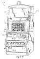
- FIG. 1Ais a perspective view of a free standing gaming machine embodying the present invention
- FIG. 1Bis a perspective view of a handheld gaming machine embodying the present invention.
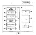
- FIG. 2is a block diagram of a control system suitable for operating the gaming machines of FIGS. 1 a and 1 b;
- FIG. 3is a side view of the display region of the gaming machine in accordance with one embodiment of the invention.
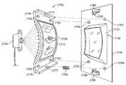
- FIGS. 4A and 4Bare a side view and a perspective view, respectively, of the display region of the gaming machine in accordance with another embodiment of the invention.
- FIGS. 5A , 5 B, 5 C and 5 Dare side views of the display region of a gaming machine illustrating various projection systems in accordance with other embodiments of the invention.
- FIGS. 6A , 6 B, 6 C, 6 D and 6 Eare side views of the display region of a gaming machine illustrating various support and drive systems in accordance with embodiments of the invention
- FIGS. 7A and 7Bare top views of the display region of a gaming machine illustrating additional projection systems in accordance with embodiments of the invention.
- FIGS. 8A and 8Bare side views of the display region of a gaming machine illustrating additional projection systems in accordance with embodiments of the invention.
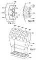
- FIGS. 9A and 9Bare a side view and an end view, respectively, of the display device for use in the display region of the gaming machine in accordance with yet another embodiment of the invention.
- FIGS. 10A and 10Bare a perspective view and a side view, respectively, of an OLED display device for use in the display region of the gaming machine in accordance with yet another embodiment of the invention.
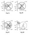
- FIGS. 11A and 11Billustrate other types of image enhancements that can be obtained by the various embodiments of the present invention.
- FIGS. 12A and 12Bare a perspective view and a side view, respectively, of a multi-unit display device for use in the display region of the gaming machine in accordance with yet another embodiment of the invention.
- FIG. 13is a perspective view of the display region of the gaming machine in accordance with yet another embodiment of the invention.
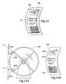
- FIG. 14is a perspective view of an OLED display device overlaying a standard mechanical reel strip in accordance with another embodiment of the present invention.
- FIGS. 15A and 15Bare a side view and a perspective view, respectively, of the display region of the gaming machine in accordance with a further embodiment of the present invention.
- FIG. 16is a side view of the display region of the gaming machine in accordance with yet another embodiment of the present invention.
- FIG. 17is a side view of the display region of the gaming machine in accordance with yet a further embodiment of the present invention.
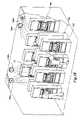
- FIG. 18is a perspective view of a typical gaming environment having a plurality of gamine machine banks
- FIG. 19A , 19 B and 19 Care different views of one gaming machine allowing for adjustments based on a player's position within the typical gaming environment of FIG. 18 ;
- FIGS. 20A , 20 B and 20 Cillustrate variations to the images of the reels strips produced by the video device in response to changes in the gaming environment surrounding the gaming machine of FIG. 19 ;
- FIG. 21illustrates variations to the images of the reels strips produced by the video device that replicate typical imperfections located on a mechanical reel strip.
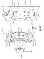
- FIG. 22is a side view of the display region of a gaming machine in accordance with yet a further embodiment of the invention.
- FIG. 23is a perspective view of a rotatable mechanical structure of a gaming machine in accordance with embodiments of the invention.
- FIG. 24is a side view and perspective view of a display region of a gaming machine in accordance with embodiments of the invention.
- FIG. 25is a side view of a display region of a gaming machine in accordance with another embodiment of the invention.
- FIG. 26is a side view of a display region of a gaming machine in accordance with yet a further embodiment of the invention.
- FIG. 27illustrates a perspective view for a floating screen assembly in accordance with embodiments of the invention.
- FIGS. 28A and 28Billustrate a side view and a top view of a floating screen assembly in accordance with embodiments of the invention.
- FIG. 29illustrates a perspective view of a plurality of floating screen assemblies in accordance with embodiments of the invention.
- a gaming machine 10is used in gaming establishments such as casinos.
- the gaming machine 10may be any type of gaming machine and may have varying structures and methods of operation.
- the gaming machine 10may be an electromechanical gaming machine configured to play mechanical slots, or it may be an electronic gaming machine configured to play a video casino game, such as blackjack, slots, keno, poker, blackjack, roulette, etc.
- the gaming machine 10comprises a housing 12 and includes input devices, including a value input device 18 and a player input device 24 .
- the gaming machine 10includes a primary display 14 for displaying information about the basic wagering game.
- the primary display 14can also display information about a bonus wagering game and a progressive wagering game.
- the gaming machine 10may also include a secondary display 16 for displaying game events, game outcomes, and/or signage information. While these typical components found in the gaming machine 10 are described below, it should be understood that numerous other elements may exist and may be used in any number of combinations to create various forms of a gaming machine 10 .
- the value input device 18may be provided in many forms, individually or in combination, and is preferably located on the front of the housing 12 .
- the value input device 18receives currency and/or credits that are inserted by a player.
- the value input device 18may include a coin acceptor 20 for receiving coin currency (see FIG. 1 a ).
- the value input device 18may include a bill acceptor 22 for receiving paper currency.
- the value input device 18may include a ticket reader, or barcode scanner, for reading information stored on a credit ticket, a card, or other tangible portable credit storage device.
- the credit ticket or cardmay also authorize access to a central account, which can transfer money to the gaming machine 10 .
- the player input device 24comprises a plurality of push buttons 26 on a button panel for operating the gaming machine 10 .
- the player input device 24may comprise a touch screen 28 mounted by adhesive, tape, or the like over the primary display 14 and/or secondary display 16 .
- the touch screen 28contains soft touch keys 30 denoted by graphics on the underlying primary display 14 and used to operate the gaming machine 10 .
- the touch screen 28provides players with an alternative method of input. A player enables a desired function either by touching the touch screen 28 at an appropriate touch key 30 or by pressing an appropriate push button 26 on the button panel.
- the touch keys 30may be used to implement the same functions as push buttons 26 .
- the push buttons 26may provide inputs for one aspect of the operating the game, while the touch keys 30 may allow for input needed for another aspect of the game.
- other player input devices 24such as a pull arm or joystick, which a player may push or pull or move left and right, are used to provide other input interfaces to operate the gaming machine 10 .
- the various components of the gaming machine 10may be connected directly to, or contained within, the housing 12 , as seen in FIG. 1 a , or may be located outboard of the housing 12 and connected to the housing 12 via a variety of different wired or wireless connection methods.
- the gaming machine 10comprises these components whether housed in the housing 12 , or outboard of the housing 12 and connected remotely.
- the operation of the basic wagering gameis displayed to the player on the primary display 14 .
- the primary display 14can also display the bonus game associated with the basic wagering game.
- the primary display 14may take the form of a cathode ray tube (CRT), a high resolution LCD, a plasma display, an LED, or any other type of display suitable for use in the gaming machine 10 .
- the primary display 14includes the touch screen 28 overlaying the entire display (or a portion thereof) to allow players to make game-related selections.
- the primary display 14 of the gaming machine 10may include a number of mechanical reels to display the outcome in visual association with at least one payline 32 .
- the gaming machine 10is an “upright” version in which the primary display 14 is oriented vertically relative to the player.
- the gaming machinemay be a “slant-top” version in which the primary display 14 is slanted at about a thirty-degree angle toward the player of the gaming machine 10 .
- a playerbegins play of the basic wagering game by making a wager via the value input device 18 of the gaming machine 10 .
- a playercan select play by using the player input device 24 , via the buttons 26 or the touch screen keys 30 .
- the basic gameconsists of a plurality of symbols arranged in an array, and includes at least one payline 32 that indicates one or more outcomes of the basic game. Such outcomes are randomly selected in response to the wagering input by the player. At least one of the plurality of randomly-selected outcomes may be a start-bonus outcome, which can include any variations of symbols or symbol combinations triggering a bonus game.
- the gaming machine 10may also include a player information reader 52 that allows for identification of a player by reading a card with information indicating his or her true identity.
- the player information reader 52is shown in FIG. 1 a as a card reader, but may take on many forms including a ticket reader, bar code scanner, RFID transceiver or computer readable storage medium interface.
- identificationis generally used by casinos for rewarding certain players with complimentary services or special offers. For example, a player may be enrolled in the gaming establishment's loyalty club and may be awarded certain complimentary services as that player collects points in his or her player-tracking account. The player inserts his or her card into the player information reader 52 , which allows the casino's computers to register that player's wagering at the gaming machine 10 .
- the gaming machine 10may use the secondary display 16 or other dedicated player-tracking display for providing the player with information about his or her account or other player-specific information. Also, in some embodiments, the information reader 52 may be used to restore game assets that the player achieved and saved during a previous game session.
- the handheld gaming machine 110is preferably an electronic gaming machine configured to play a video casino game such as, but not limited to, blackjack, slots, keno, poker, blackjack, and roulette.
- the handheld gaming machine 110comprises a housing or casing 112 and includes input devices, including a value input device 118 and a player input device 124 .
- the handheld gaming machine 110includes, but is not limited to, a primary display 114 , a secondary display 116 , one or more speakers 117 , one or more player-accessible ports 119 (e.g., an audio output jack for headphones, a video headset jack, etc.), and other conventional I/O devices and ports, which may or may not be player-accessible.
- the handheld gaming machine 110comprises a secondary display 116 that is rotatable relative to the primary display 114 .
- the optional secondary display 116may be fixed, movable, and/or detachable/attachable relative to the primary display 114 .
- Either the primary display 114 and/or secondary display 116may be configured to display any aspect of a non-wagering game, wagering game, secondary games, bonus games, progressive wagering games, group games, shared-experience games or events, game events, game outcomes, scrolling information, text messaging, emails, alerts or announcements, broadcast information, subscription information, and handheld gaming machine status.
- the player-accessible value input device 118may comprise, for example, a slot located on the front, side, or top of the casing 112 configured to receive credit from a stored-value card (e.g., casino card, smart card, debit card, credit card, etc.) inserted by a player.
- a stored-value carde.g., casino card, smart card, debit card, credit card, etc.
- the player-accessible value input device 118may comprise a sensor (e.g., an RF sensor) configured to sense a signal (e.g., an RF signal) output by a transmitter (e.g., an RF transmitter) carried by a player.
- the player-accessible value input device 118may also or alternatively include a ticket reader, or barcode scanner, for reading information stored on a credit ticket, a card, or other tangible portable credit or funds storage device.
- the credit ticket or cardmay also authorize access to a central account, which can transfer money to the handheld gaming machine 110 .
- Still other player-accessible value input devices 118may require the use of touch keys 130 on the touch-screen display (e.g., primary display 114 and/or secondary display 116 ) or player input devices 124 .
- touch keys 130 on the touch-screen displaye.g., primary display 114 and/or secondary display 116
- player input devices 124Upon entry of player identification information and, preferably, secondary authorization information (e.g., a password, PIN number, stored value card number, predefined key sequences, etc.), the player may be permitted to access a player's account.
- secondary authorization informatione.g., a password, PIN number, stored value card number, predefined key sequences, etc.
- the handheld gaming machine 110may be configured to permit a player to only access an account the player has specifically set up for the handheld gaming machine 110 .
- the player-accessible value input device 118may itself comprise or utilize a biometric player information reader which permits the player to access available funds on a player's account, either alone or in combination with another of the aforementioned player-accessible value input devices 118 .
- the player-accessible value input device 118comprises a biometric player information reader
- transactionssuch as an input of value to the handheld device, a transfer of value from one player account or source to an account associated with the handheld gaming machine 110 , or the execution of another transaction, for example, could all be authorized by a biometric reading, which could comprise a plurality of biometric readings, from the biometric device.
- a transactionmay be optionally enabled only by a two-step process in which a secondary source confirms the identity indicated by a primary source.
- a player-accessible value input device 118comprising a biometric player information reader may require a confirmatory entry from another biometric player information reader 152 , or from another source, such as a credit card, debit card, player ID card, fob key, PIN number, password, hotel room key, etc.
- a transactionmay be enabled by, for example, a combination of the personal identification input (e.g., biometric input) with a secret PIN number, or a combination of a biometric input with a fob input, or a combination of a fob input with a PIN number, or a combination of a credit card input with a biometric input.
- the personal identification inpute.g., biometric input
- a secret PIN numbere.g., biometric input
- a biometric input with a fob inpute.g., a secret PIN number
- a biometric inpute.g., biometric input
- fob inpute.g., a combination of a fob input with a PIN number
- a credit card inpute.g., debit card
- biometric input device 118may be provided remotely from the handheld gaming machine 110 .
- the player input device 124comprises a plurality of push buttons on a button panel for operating the handheld gaming machine 110 .
- the player input device 124may comprise a touch screen 128 mounted to a primary display 114 and/or secondary display 116 .
- the touch screen 128is matched to a display screen having one or more selectable touch keys 130 selectable by a user's touching of the associated area of the screen using a finger or a tool, such as a stylus pointer.
- a playerenables a desired function either by touching the touch screen 128 at an appropriate touch key 130 or by pressing an appropriate push button 126 on the button panel.
- the touch keys 130may be used to implement the same functions as push buttons 126 .
- the push buttonsmay provide inputs for one aspect of the operating the game, while the touch keys 130 may allow for input needed for another aspect of the game.
- the various components of the handheld gaming machine 10may be connected directly to, or contained within, the casing 112 , as seen in FIG. 1 b , or may be located outboard of the casing 112 and connected to the casing 112 via a variety of hardwired (tethered) or wireless connection methods.
- the handheld gaming machine 110may comprise a single unit or a plurality of interconnected parts (e.g., wireless connections) which may be arranged to suit a player's preferences.
- the operation of the basic wagering game on the handheld gaming machine 10is displayed to the player on the primary display 114 .
- the primary display 114can also display the bonus game associated with the basic wagering game.
- the primary display 114preferably takes the form of a high resolution LCD, a plasma display, an LED, or any other type of display suitable for use in the handheld gaming machine 110 .
- the size of the primary display 114may vary from, for example, about a 2-3′′ display to a 15′′ or 17′′ display. In at least some aspects, the primary display 114 is a 7′′-10′′ display. As the weight of and/or power requirements of such displays decreases with improvements in technology, it is envisaged that the size of the primary display may be increased.
- coatings or removable films or sheetsmay be applied to the display to provide desired characteristics (e.g., anti-scratch, anti-glare, bacterially-resistant and anti-microbial films, etc.).
- the primary display 114 and/or secondary display 116may have a 16:9 aspect ratio or other aspect ratio (e.g., 4:3).
- the primary display 114 and/or secondary display 116may also each have different resolutions, different color schemes, and different aspect ratios.
- a playerbegins play of the basic wagering game on the handheld gaming machine 110 by making a wager (e.g., via the value input device 18 or an assignment of credits stored on the handheld gaming machine via the touch screen keys 130 , player input device 124 , or buttons 126 ) on the handheld gaming machine 110 .
- the basic gamemay comprise a plurality of symbols arranged in an array, and includes at least one payline 132 that indicates one or more outcomes of the basic game. Such outcomes are randomly selected in response to the wagering input by the player. At least one of the plurality of randomly selected outcomes may be a start-bonus outcome, which can include any variations of symbols or symbol combinations triggering a bonus game.
- the player-accessible value input device 118 of the handheld gaming machine 110may double as a player information reader 152 that allows for identification of a player by reading a card with information indicating the player's identity (e.g., reading a player's credit card, player ID card, smart card, etc.).
- the player information reader 152may alternatively or also comprise a bar code scanner, RFID transceiver or computer readable storage medium interface.
- the player information reader 152shown by way of example in FIG. 1 b , comprises a biometric sensing device.
- a central processing unit (CPU) 34also referred to herein as a controller or processor (such as a microcontroller or microprocessor).
- the controller 34executes one or more game programs stored in a computer readable storage medium, in the form of memory 36 .
- the controller 34performs the random selection (using a random number generator (RNG)) of an outcome from the plurality of possible outcomes of the wagering game.
- RNGrandom number generator
- the random eventmay be determined at a remote controller.
- the remote controllermay use either an RNG or pooling scheme for its central determination of a game outcome.
- the controller 34may include one or more microprocessors, including but not limited to a master processor, a slave processor, and a secondary or parallel processor.
- the controller 34is also coupled to the system memory 36 and a money/credit detector 38 .
- the system memory 36may comprise a volatile memory (e.g., a random-access memory (RAM)) and a non-volatile memory (e.g., an EEPROM).
- RAMrandom-access memory
- EEPROMnon-volatile memory
- the system memory 36may include multiple RAM and multiple program memories.
- the money/credit detector 38signals the processor that money and/or credits have been input via the value input device 18 .
- these componentsare located within the housing 12 of the gaming machine 10 . However, as explained above, these components may be located outboard of the housing 12 and connected to the remainder of the components of the gaming machine 10 via a variety of different wired or wireless connection methods.
- the controller 34is also connected to, and controls, the primary display 14 , the player input device 24 , and a payoff mechanism 40 .
- the payoff mechanism 40is operable in response to instructions from the controller 34 to award a payoff to the player in response to certain winning outcomes that might occur in the basic game or the bonus game(s).
- the payoffmay be provided in the form of points, bills, tickets, coupons, cards, etc.
- the payoff mechanism 40includes both a ticket printer 42 and a coin outlet 44 .
- any of a variety of payoff mechanisms 40 well known in the artmay be implemented, including cards, coins, tickets, smartcards, cash, etc.
- the payoff amounts distributed by the payoff mechanism 40are determined by one or more pay tables stored in the system memory 36 .
- I/O circuits 46 , 48Communications between the controller 34 and both the peripheral components of the gaming machine 10 and external systems 50 occur through input/output (I/O) circuits 46 , 48 . More specifically, the controller 34 controls and receives inputs from the peripheral components of the gaming machine 10 through the input/output circuits 46 . Further, the controller 34 communicates with the external systems 50 via the I/O circuits 48 and a communication path (e.g., serial, parallel, IR, RC, 10bT, etc.). The external systems 50 may include a gaming network, other gaming machines, a gaming server, communications hardware, or a variety of other interfaced systems or components. Although the I/O circuits 46 , 48 may be shown as a single block, it should be appreciated that each of the I/O circuits 46 , 48 may include a number of different types of I/O circuits.
- Controller 34comprises any combination of hardware, software, and/or firmware that may be disposed or resident inside and/or outside of the gaming machine 10 that may communicate with and/or control the transfer of data between the gaming machine 10 and a bus, another computer, processor, or device and/or a service and/or a network.
- the controller 34may comprise one or more controllers or processors. In FIG. 2 , the controller 34 in the gaming machine 10 is depicted as comprising a CPU, but the controller 34 may alternatively comprise a CPU in combination with other components, such as the I/O circuits 46 , 48 and the system memory 36 .
- the controller 34may reside partially or entirely inside or outside of the machine 10 .
- the control system for a handheld gaming machine 110may be similar to the control system for the free standing gaming machine 10 except that the functionality of the respective on-board controllers may vary.
- the gaming machines 10 , 110may communicate with external systems 50 (in a wired or wireless manner) such that each machine operates as a “thin client,” having relatively less functionality, a “thick client,” having relatively more functionality, or through any range of functionality therebetween (e.g., a “rich client”).
- a “thin client”the gaming machine may operate primarily as a display device to display the results of gaming outcomes processed externally, for example, on a server as part of the external systems 50 .
- the serverexecutes game code and determines game outcomes (e.g., with a random number generator), while the controller 34 on board the gaming machine processes display information to be displayed on the display(s) of the machine.
- the serverdetermines game outcomes, while the controller 34 on board the gaming machine executes game code and processes display information to be displayed on the display(s) of the machines.
- the controller 34 on board the gaming machine 110executes game code, determines game outcomes, and processes display information to be displayed on the display(s) of the machine.
- Numerous alternative configurationsare possible such that the aforementioned and other functions may be performed onboard or external to the gaming machine as may be necessary for particular applications.
- the gaming machines 10 , 110may take on a wide variety of forms such as a free standing machine, a portable or handheld device primarily used for gaming, a mobile telecommunications device such as a mobile telephone or personal digital assistant (PDA), a counter top or bar top gaming machine, or other personal electronic device such as a portable television, MP3 player, entertainment device, etc.
- a mobile telecommunications devicesuch as a mobile telephone or personal digital assistant (PDA), a counter top or bar top gaming machine, or other personal electronic device such as a portable television, MP3 player, entertainment device, etc.
- PDApersonal digital assistant
- other personal electronic devicesuch as a portable television, MP3 player, entertainment device, etc.
- FIG. 3illustrates one embodiment used for the primary display 14 of gaming machine 10 .
- a transparent layer 150is located within an outer window 154 , which is attached to the housing 155 of the gaming machine 10 .
- the transparent layer 150has a radius of curvature that is similar to the radius of curvature of a mechanical reel used within a mechanical-reel style of gaming machine 10 (e.g., four inches to seven inches). Although it is referred to as the “transparent” layer 150 , the transparent layer 150 can be semi-transparent or semi-transparent for only certain wavelengths of light, such as various polymeric materials.
- a video display device 160is a projection device that transmits and projects images onto the transparent layer 150 .
- the video display device 160can be an LCD projection device or a DLP projection device that creates images on the transparent layer 150 .
- Other examples of a video display device 160can include traditional projection technologies or other systems, such as liquid crystal on silicon (LCoS) technology, heads-up display (HUD), light pipe displays, fiber optic displays and laser projection displays (e.g., a three-colored laser).
- the images produced by the video display device 160are dynamic images that move in a manner that is similar to the movement of symbols on a mechanical reel. Accordingly, the images include a plurality of symbols used for indicating the randomly selected outcome of the wagering game.
- the imagesappear to be symbols rotating on a mechanical reel having a radius of curvature equivalent to the radius of curvature of the transparent layer 150 .
- the imagescan be a high-resolution output, such as an 800 ⁇ 600 pixel display, or greater, or other suitable resolution that would be considered high-resolution to those familiar with the field of disclosure.
- the video display device 160 and transparent layer 150can be mounted to one common structure 170 located within the housing 155 .
- the transparent layer 150can be mounted directly to the housing 155 (like the window 154 ) because the transparent layer 150 does not rotate or move whatsoever.
- the video display device 160can project images onto the inside surface of the transparent layer 150 (that is, rear projection) as illustrated for example in FIG. 3 .
- the video display device 160can project images on an outside surface of the transparent layer 150 (that is, front projection).
- front projectionthe video display device 160 can be located in the area between adjacent reels or simulated reels or from the area above or below the reels. In either a front or rear projection system, the video display device is out of the line-of-sight of a player of the gaming machine.
- the window 154is of the type that is used in typical mechanical slot machines.
- the window 154may have artwork with a theme that matches the game.
- Miniature display meterscan be mounted to the window 154 to provide information (e.g., total credits, credits being wagered, etc.) to the player.
- FIG. 3is shown with respect to a single reel, it can be replicated several times on adjacent reels (e.g., three or five times to produce three or five simulated mechanical reels). As such, the gaming machine 10 would appear as a three-reel slot machine or a five-reel slot machine.
- the video display device 160can have a size that allows it to provide images for more than one (or all) of the simulated mechanical reels.
- strobe projection using a single video display device 160is used.
- the video display device 160sequentially outputs multiple image signals onto respective multiple transparent layers 150 using frequency cycles greater than can be perceived by the human eye.
- imagescan be projected from the side of a series of reels using sequential mirrors within the reels to split the signal projected from the video display device 160 .
- the projection distance from the video display device to the transparent layercan vary based on a number of factors including focal length, mechanical limitations, spatial limitations, lensing abilities and other factors that depend on the type of video display device, the type of transparent surface and the type of reel being used. In certain embodiments, the projection distance varies from one inch to several inches.
- FIGS. 4A and 4Billustrate an alternative embodiment in which the primary display 14 includes a transparent layer 200 that moves within the housing 155 adjacent to the window 154 .
- the radius of curvature of the transparent layer 200is similar to the radius of curvature of a mechanical reel within a typical slot machine.
- the video display device 210is located within a transparent layer 200 and projects moving images onto the moving transparent layer 200 .
- the velocity of the moving images produced by the video display device 210generally corresponds to the velocity of the movement of the transparent layer 200 .
- the image projected onto the transparent layer 200is synchronized with the movement of the transparent layer 200 .
- the gaming machine 10would typically include a device coupled to the drum or cage rotating the transparent layer, such as an encoder, that can be used to measure the angular position and, thus, the angular velocity of the transparent layer 200 so that the movement of the images can accelerate and decelerate as needed.
- a device coupled to the drum or cage rotating the transparent layersuch as an encoder, that can be used to measure the angular position and, thus, the angular velocity of the transparent layer 200 so that the movement of the images can accelerate and decelerate as needed.
- synchronizationis not used and the transparent layer 200 moves at a different velocity as the images.
- the transparent layer 200is mounted in a fashion that is similar to a mechanical reel in that it includes a central axis 215 and support struts 225 leading from the central axis 215 to the transparent layer 200 or a drum supporting the transparent layer 200 .
- the central axis 215is located on a mounting structure 230 within the housing 155 of the gaming machine 10 .
- the video display device 210can be mounted on a separate structure within the housing 155 , the video display device 210 is mounted onto a portion 220 of the same mounting structure 230 in the illustrated embodiment of FIG. 4 . Accordingly, as the transparent layer 200 rotates around the central axis 215 , any vibrations or off-axis movements may cause the video display device 210 to produce slight imperfections in the images (i.e., “jitter” of the images), which is similar to the imperfect motion achieved by traditional mechanical reels. This “jitter” of the images of the video display device 210 can be advantageous, as is described below with respect to FIG. 21 .
- the transparent layer 200 and the video display device 210can both be mounted on the mounting structure 230 in a manner that includes a vibration-reduction mechanism to minimize or remove the inherent vibrations that may be experienced by the video display device 210 .
- FIG. 4Billustrates the video display device 210 and the transparent layer 200 (dashed lines) from the front of the gaming machine 10 .
- the video display device 210projects images onto the transparent layer 200 such that there are three distinct symbol locations 232 a , 232 b , 232 c . Accordingly, subsequent to the spinning motion associated with the images from the video display device 210 , the images come to a stop such that they are static images of symbols used for indicating the randomly selected outcome, as shown by the symbols in the primary display 14 of FIG. 1 . While FIGS. 4A and 4B have been described as having one display device 210 to create one simulated mechanical reel, one long display device 210 can be used to create the images on a plurality of rotating transparent layers 200 , creating a plurality of simulated mechanical reels.
- the display device 210includes a plurality of the display devices located entirely around the central axis 215 such that images can be produced around the entire circumference of the transparent layer 200 .
- the display devicesrotate with the transparent layer 200 such that each display device inherently controls the images along a fixed portion of the circumference of the transparent layer 200 .
- FIGS. 5A-5Dillustrate several alternative embodiments for locating a video display device 610 of a gaming machine 10 relative to a projection layer 700 .
- the embodiments of FIGS. 5A-5Dinclude a rotatable mechanical structure 640 that can spin about a central axis 615 .
- the rotatable structure 640can be secured to a mounting structure 630 .
- the primary display 614includes a projection surface 700 mounted to the rotatable structure 640 that moves within a housing 655 adjacent to a window 654 .
- the radius of curvature of the projection surface 700is similar to the radius of curvature of a mechanical reel or other rotatable mechanical structure within a typical slot machine.
- the projection surface 700can include, for example, a transparent layer, a semi-transparent layer, or a non-transparent layer.
- a transparent layeris typically used.
- a non-transparent layeris typically used such as a textile-backed or non-textile-backed projection surface.
- Video display device 610can be mounted below or behind the central axis 615 and project images, either, directly onto the projection surface 700 , or indirectly using mirrors, lenses, and/or light piping display technology.
- the video display device 610 in FIGS. 5A-5Cis located within the projection surface 700 and is used to project moving images onto the projection surface 700 .
- the video display device 610is mounted between the central axis 615 and the primary display 614 behind the projection surface 700 .
- the video display device in FIG. 5Ais mounted within the gaming machine 10 away from the central axis 615 .
- the video display device 610is mounted below the central axis 615 and projects an image onto the projection surface 700 at an upward angle toward primary display 614 .
- the video display device 610is located behind the central axis 615 away from the primary display 614 .
- the video display device 610can project an image at a downward angle (shown) or an upward angle (not shown) toward a mirror 620 which reflects the projected image onto the projection surface 700 in a direction toward the primary display 614 .
- the video display device 610is located outside of the rotatable structure 640 and projects images within the primary display 614 at either a downward angle (shown) or an upward angle (not shown) onto the outside surface of projection surface 700 .
- the projection surfaceis a curved reel strip for a mechanical reel typically used in a slots game.
- the video display device 610can project images from either the left or the right of the projection surface 700 .
- FIGS. 6A-6Eillustrate examples of alternate support systems and drive systems for a projection surface 700 .
- the use of alternate support and drive systemscan increase the flexibility by which a video display device 610 is located within a gaming machine 10 .
- the projection surface 700is supported at the periphery with a rotatable mechanical structure 641 .
- FIG. 6Aillustrates the use of a gear 660 to drive the mechanical structure 641 (e.g., mechanical reel) to which the projection surface 700 is mounted.
- the mechanical structure 641can be driven, in certain embodiments, using an edge-driven direct-gear drive or a worm-gear drive. Additional gears can also be used to rotate the mechanical structure 641 .
- Two rollers 661can be used in certain embodiments to support the mechanical structure 641 at the periphery.
- the rollers 661roll similar to a train wheel rotating along a smooth track 643 , or in the case of the gear 660 , a toothed track 644 .
- the tracks 643 , 644 in FIG. 6Aare located on the inside of the rotatable structure 641 .
- the projection surface 700is supported about a central axis 615 using a drive belt 645 to rotate a mechanical structure 642 , which supports the projection surface 700 .
- the drive belt 645can engage the mechanical structure 642 on a track 646 along the outside circumference of the mechanical structure 642 .
- the drive belt 645can engage an axle 616 rotatable about the central axis 615 .
- the projection surface 700is supported using a three-point support system based on three rollers 662 , 663 rotatable about an outside track 648 ( FIG. 6C ) or an inside track 649 ( FIG. 6D ). Additional rollers can be used to support the projection surface 700 .
- the projection surface 700can also be mounted to a mechanical structure 647 , 651 .
- the rollers 662 , 663can operate along a smooth track similar to the rollers described for FIG. 6A .
- the rollers 662 , 663have sufficient frictional or other mechanical contact with the track 648 , 649 to rotate the mechanical structure 647 , 651 .
- the projection surface 700is arranged to move continuously in a generally non-circular manner about a group of rollers 670 .
- the projection surface 700can move in an arc-shaped circular path to simulate or give the appearance to a player of a mechanical reel.
- the configuration of FIG. 6Eallows additional alternatives to place the video display device 610 .
- Additional rollers 672can be used to support and shape the projection surface 700 to give it an arc-shaped circular path as is passed along the primary display 614 .
- FIGS. 7A-7Ba top view is illustrated for the video display device 710 of a gaming machine in which, for example, a single video display device 710 is used to project onto multiple projection surfaces 750 .
- a single video display device 710projects images onto three projection surfaces 750 .
- the projection surfacescan be mounted to rotatable mechanical structures similar to the gaming machines illustrated in FIGS. 4-6 .
- the location of the video display device 710can also vary similar to the examples illustrated in FIGS. 4-6 .
- a video display splitter or similar device within the video display device 710can be used to allow a single video display device 710 to project separate images onto three separate projection surfaces 750 .
- the single video display device 710can have three separate projectors directed to the three projection surfaces 750 for displaying the projected images.
- strobe projectioncan be used in which images are alternately or sequentially projected onto the respective three projection surfaces 750 , one image at a time, but at frequency cycles greater than can be perceived by the human eye so that the impression of a human observer is that the images are being projected continuously onto all three projection surfaces 750 .
- a single video display device 710projects images from the side (parallel to the axis of rotation) of the rotatable mechanical structures 740 . The image is projected onto a mirror 760 located within the respective mechanical structure 740 which directs the image onto a projection surface 750 .
- a video display splitter or other devices described for FIG. 7A or similar systemscan be used to project the multiple images onto the mirror 760 with subsequent projection onto projection surface 750 from a single video display device 710 .
- a single video display device 710can also be used to project images onto more than three or less than three projection surfaces.
- FIGS. 8A and 8Billustrate the use of light piping or an image conduit to project an image from a video display device 810 onto a projection surface 800 .
- An image conduittypically comprises a number of multifiber bundles of single fibers that are fused together to carry an actual image.
- the single fibers used to build the image conduitare a simple form of fiber optics and are typically available in diameters from about 0.020 to 2.0 millimeters, but smaller or larger structures can be used for certain applications.
- An image conduitcan be bent to almost any desired path for projecting the image from the video display device 810 onto the projection surface 800 .
- an image conduitcould be used to carry the image projected from the video display device 810 around the motor and onto a projection surface viewable by a player of a gaming machine.
- the image conduitmakes the image at the first surface (e.g., near the video display device 810 ) appear as though it is “on” the second surface (e.g., the projection surface), which is the surface that the player views.
- the video display device 810is a flat element that is coupled to image conduit 880 .
- the video display device 810 and image conduit 880can be located outside of the space defined by a rotatable mechanical structure 840 .
- the rotatable structure 840can comprise the projection surface 800 or the projection surface 800 can be mounted to the rotatable structure 840 .
- the image conduit 880can bend to enter the space defined by the rotatable structure 840 to project images from the video display device 810 to the projection surface 800 .
- a video display device 815can project an image onto a transparent layer 890 .
- An image conduit 885 on the opposite side of the transparent layer 890can then carry images onto projection surface 805 for viewing by the gaming machine player. Similar to FIG. 8A , the projection surface 805 can be mounted to a rotatable mechanical structure 845 .
- an image conduitcan act as a multiplexing optical device for splitting a video feed from a video display device.
- Such an application of an image conduitcan be beneficial, for example, where a video display device is used to project images onto a plurality of projection surfaces, as illustrated, for example, in FIGS. 7A-7B .
- the image conduit for such a configurationis divided into one separate section for every projection surface the image conduit provides images.
- the image conduitis divided in five sections.
- Each section of the image conduitcarries an apportioned image from the video display device to a lensing element which projects the image onto the respective projection surface on the respective reel strip.
- an optical waveguidecan carry an image from a projection source such as a video display device to a wedge-shaped planar light guide where the image can be reflected onto the wedge shape and subsequently be projected onto a projection surface in the gaming machine.
- the path the optical waveguide can take before the image is displayed on the projection surfacecan include any of a number of routes in the gaming machine, such as between the slot reels.
- FIGS. 3-8While several embodiments of a gaming machine have been described herein, various combinations of the support systems, drive mechanisms and projection systems illustrated in FIGS. 3-8 are contemplated.
- FIGS. 9A and 9Billustrate an alternative embodiment in which a flat panel video display 235 projects images upwardly through a lens 240 on to the transparent layer 200 .
- a lens 240 or a lens systeme.g., a plurality of fiber optic lenses
- FIGS. 10A and 10Billustrate yet another alternative embodiment in which a curved organic light-emitting diode (OLED) display 260 is used to project moving symbols onto the transparent layer 200 .
- OLEDorganic light-emitting diode
- the OLED display 260provides a plurality of images of symbols 262 a , 262 b , 262 c that are used to indicate a randomly selected outcome of the wagering game.
- the gaming machine 10can also use a polymeric light emitting diode (PLED) display as well.
- PLEDpolymeric light emitting diode
- the transparent layer 200is replaced by a typical reel strip having permanent symbols.
- the OLED display 260is then used for backlighting the reel strip and highlighting certain features on the reel strip. For example, if a symbol is a part of the winning symbol combination, the OLED display 260 can provide highlighting (e.g., flashing stars) around that winning symbol.
- FIG. 11Aillustrates the individual “BAR” symbol 262 c of FIG. 10A being dynamically changed to a “WILD” symbol 264 . This change may occur while the symbol 262 c is in motion, or after the symbol 262 c has come to a rest. The change may be a gradual “morphing” of the symbol, or it can be an instantaneous transition.
- FIG. 11Billustrates the fact that all of the symbols 262 of FIG. 10A can be completely changed to other symbols during motion or after the symbols 262 have come to rest.
- the symbols 262 of FIG. 10Ahave been changed to a “SHOOTING STAR” symbol 266 during motion of the images produced by the video display device 260 .
- the “SHOOTING STAR” symbol 266may indicate that a positive outcome will occur when the reels come to a stop, providing the player with enhanced excitement.
- the video display devices 160 , 210 , 235 , 260provides flexibility to add various enhancements to the overall player experience at the gaming machine 10 .
- FIGS. 3-11illustrate one continuous video display device 160 , 210 , 235 , 260 , 610 , 710 , 810 , 815 for providing the images
- FIGS. 12A-12Bdisclose an alternative embodiment in which three distinct video display devices 270 a , 270 b , 270 c provide images that abut, or overlap, each other when projected onto the transparent layer 200 .
- Each of the video display devices 270 a , 270 b , 270 cis preferably mounted on one printed circuit board 280 and are controlled by one controller.
- Each of the video display devices 270 a , 270 b , 270 cprovides images at locations 282 a , 282 b , 282 c on the transparent layer 200 .
- an image of the symbolis first projected by the video display device 270 a .
- the imagemoves downwardly, it is the projected by the video display device 270 b and, finally, by video display device 270 c .
- a portion of a single image of a symbole.g., a “SEVEN” symbol
- the video display device 270 a and the video display device 270 bcan be projected by the video display device 270 a and the video display device 270 b as that image moves between (i.e., straddles) the symbol location 282 a and the symbol location 282 b on the transparent layer 200 .
- FIGS. 5-11have been shown with respect to the rotating transparent layer 200 , 700 , 800 , 805 , it should be understood that each of these embodiments can be used with a static transparent layer, such as the transparent layer 150 of FIG. 3 .
- FIG. 13illustrates an alternative embodiment in which a flat-panel video display 320 (e.g., an LCD display) projects images through a formed light pipe 325 or image conduit (e.g., an image carrier comprising a fusion of coherent bundles of fused single fibers that behave mechanically like a single glass fiber) to five output stations 330 a - 330 e .
- a formed light pipe 325 or image conduite.g., an image carrier comprising a fusion of coherent bundles of fused single fibers that behave mechanically like a single glass fiber
- Each of the plurality of output stations 330 a - 330 ecorresponds to one reel on the gaming machine 10 .
- the imagefollows a path 332 through the light pipe 325 , leading to a corresponding segment 335 b along the first output station 330 a.
- the system of FIG. 13can be used with a stationary transparent layer, such as the transparent layer 150 of FIG. 3 .
- the video display device 320can be located closer to the plurality of output stations 330 such that the dimensions of the light pipe 325 are reduced.
- the video display device 320 , the light pipe 325 , and the output stations 330may fit within the internal diameter of the rotating transparent layer 200 , 700 , 800 of FIGS. 4-11 .
- FIG. 13illustrates embodiment in which one video display device 320 results in images projected from five distinct output stations 330 .
- FIG. 14illustrates an alternative embodiment with a conventional mechanical reel strip 350 having a plurality of predefined symbols.
- the symbols on the mechanical reel strip 350are altered or highlighted by an OLED device 360 , which is partially transparent, located over the mechanical reel strip 350 .
- the OLED device 360can provide a color highlighted region 362 when a certain symbol (e.g., a “SEVEN” symbol) is achieved, resulting in a winning symbol combination or the triggering of a bonus game.
- the OLED device 360can also highlight a “scatter” payout symbol.
- the highlighting provided by the OLED device 360can be static or dynamic.
- the OLED device 360can provide additional images that overlay the underlying symbols of the reel strip 350 .
- the OLED device 360can provide paylines that traverse one reel, or a plurality of reels for indicating winning symbol combinations.
- the OLED device 360can highlight a winning payline or indicate which payline(s) the player has selected.
- a conventional mechanical reel strip having translucent propertiescan be placed in front of the OLED device so that the OLED device provides images, lighting, and highlighting from behind the conventional mechanical reel strip.
- the OLED device 260can provide addressable animation and highlighting. Winning symbols or a combination of symbols can be highlighted on the conventional mechanical reel strip by the projection of images from the OLED device 260 .
- unique shapes and graphics, as well as wordscan be projected from the OLED device 260 during or after the spinning of the conventional mechanical reel strip.
- FIGS. 15A and 15Billustrate an alternative embodiment of the display region 14 of the gaming machine 10 .
- a rotating drumincludes a layer of “electronic paper” 400 having the ability to create and remove images by placing an electronic charge on the material.
- “Electronic paper” 400can come in various forms and generally includes miniature conductive items, such as spheres, that can be rotated in a certain direction in response to an applied electronic signal.
- the applied electronic signalcauses a known surface (having a certain color, or black and white portions) on the miniature conductive item to appear in a certain direction. By applying the electronic signal at known locations, an image can be created on the electronic paper.
- FIG. 15Aillustrates electronic charge stations 410 a and 410 b just prior to the display region 14 and electronic discharge stations 420 a and 420 b subsequent to the display region 14 .
- the electronic charge stations 410 a and 410 bapply an electronic signal to the electronic paper 400 at known locations to produce certain symbols. For example, as shown best in FIG. 15B , the electronic charge stations 410 a and 410 b first create the “BAR” symbol 422 c as the electronic paper 400 moves downwardly (see the arrow in FIG. 15A ). Next, the electronic charge stations 410 a and 410 b create the “SEVEN” symbol 422 b as the electronic paper 400 continues moving in the downward direction.
- the electronic charge stations 410 a and 410 bcreates the “CHERRY” symbol 422 a as the electronic paper 400 continues the downward movement. As the electronic paper 400 continues movement, the electronic charge stations 410 a and 410 b continue to create symbols as they move into the display region 14 . The manner in which the electronic charge stations 410 a and 410 b create the symbols is a function of the angular velocity of the electronic paper 400 .
- the electronic discharge stations 420 a and 420 bcreate a neutral mode in the electronic paper 400 .
- the electronic paper 400receives an electronic charge that causes the movable miniature items (e.g., spheres) in the electronic paper 400 to be placed in all the same direction.
- the purpose of the electronic discharge stations 420 a and 420 bis to place the electronic paper 400 in a known mode or format before it reenters the electronic charge stations 410 a and 410 b .
- the electronic discharge stations 420 a and 420 bcan be considered to perform a “removal” or “erase” function.
- the electronic charge stations 410 a and 410 b and the electronic discharge stations 420 a and 420 bcan be powered by the power from the gaming machine.
- the imagesare changed between wagering games. For example, a player could play four sessions of the basic wagering gaming using the same set of images on the electronic paper 400 . During the fourth session, the player may achieve a bonus-game triggering event. At that time, the electronic discharge stations 420 a and 420 b would “erase” the images from the electronic paper 400 and the electronic charge stations 410 a and 410 b would create new images of symbols for a bonus game involving the spinning of one or more reels containing the electronic paper 400 .
- the electronic paper 400can be replaced by a rotating layer material that receives printed matter.
- the electronic charge stations 410 a and 410 bwould be considered “printing” stations for adding material at known locations to create symbols.
- the electronic discharge stations 420 a and 420 bwould be considered “erasing” stations for removing that material from the rotating layer of material.
- a video display devicemay be located internal to the rotating layer of material to create the illusion of symbols spinning.
- the “printing” stationsonly begin to function to print on the rotating layer material when it slows to a velocity at which the eye can perceive a symbol.
- the “printing” stationscan apply a UV-sensitive material to create the symbols and the “erasing” stations can remove the symbols through the application of UV light.
- the fixed symbols created on the moving mediumallow for random outcomes to be displayed in accordance with “virtual reel stops.”
- the random number generatordetermines the outcome, that outcome corresponds to a certain symbol on each reel being displayed at an appropriate position in the display region, typically along an active payline.
- One such method for creating these virtual reel stopsis disclosed in U.S. Pat. No. 4,448,419, which is herein incorporated by reference in its entirety.
- FIG. 16illustrates an embodiment in which the symbols in the display region 14 of the gaming machine 10 are provided by a plurality of cassettes 430 .
- Six distinct cassettes 430 a - 430 fare located within a transparent layer 420 , although more or less cassettes 430 can be used. Further, the transparent layer 420 may not be needed in some embodiments.
- the first cassette 430 ais located within the display region 14 and includes a reel strip 432 that is wrapped around a plurality of rollers 439 . To move the reel strip 432 , one of the rollers 439 is driven by a motor (not shown) to cause the reel strip 432 (with its associated symbols) to move through the display region 14 .
- cassette 430is the Flexi-Strip Reel Mechanism from the Starpoint Company of Chessington, Surrey, of the U.K. (http://www.starpoint.uk.com/Starpoint_WS/Gaming_Views/Flexistrip/), which is herein incorporated by reference in its entirety.
- each cassette 430includes a different set of symbols for playing different wagering games.
- the cassettes 430 a - 430 cmay include symbols for playing three different basic wagering games
- the cassettes 430 d - 430 fmay include symbols for playing three different bonus games.
- the CPU 34 of the gaming machine 10can then rotate the drum mechanism to place the cassette 430 b in the display region 14 such that the a second group of symbols on its reel strip can be displayed to the player during a second wagering game.
- the gaming machine 10has one of the drum mechanisms containing the cassettes 430 in FIG. 16 for each reel, such that a three-reel gaming machine 10 includes three mechanisms shown in FIG. 16 .
- the six distinct cassettes 430 a - 430 feach provide a known subset of the overall symbol group around the drum.
- the “reel strip”is comprised of six segments, each segment being provided by one cassette 430 .
- the entire drumrotates like a typical reel to place symbols in the display region for indicating the randomly selected outcome.
- one or more cassettes 430can use their internal rollers and place new symbols on the circumference of the drum. This symbol alteration can be done while the drum is stationary or spinning.
- FIG. 17also illustrates an embodiment in which multiple lengths of reel strips having different groups of permanent symbols can be displayed at different times.
- a rotatable drumincludes an outer structure 450 having a circumference on which a first length of reel strip 460 can be placed.
- a second length of reel strip 460 ais located internal to the drum via a gap 470 and is wrapped around a roller 480 .
- a third length of reel strip 460 bis located internal to the drum via the gap 470 and wrapped around a roller 490 .
- there are three continuous lengths of the reel strips 460 , 460 a , and 460 beach of which includes a distinct group of symbols.
- the entire drumrotates through the display region 14 such that the symbols on the reel strip 460 are repetitively displayed to the player during rotation, just like a conventional mechanical reel.
- the roller 490is driven (by a motor) to cause the first length of reel strip 460 to be wrapped around that roller 490 , while simultaneously pulling the second length 460 a from the second roller 480 onto the outer structure 450 .
- the opposite actionscan be taken to advance the third length 460 b onto the outer structure 450 .
- a different wagering gamecan be played with the different group of symbols, as discussed above with respect to FIG. 16 .
- the changes of the reel strip lengths 460 , 460 a , 460 boccur on the outer structure 450 while the drum is stationary.
- an alternative embodimentwould include four rollers. Two of the four rollers work together to provide the reel strip for half of the circumference and the other two rollers work together to provide the reel strip for the other half of the circumference. In this alternative, two gaps 470 would be needed. The two gaps 470 would preferably be located at 180° from each other.
- FIG. 18illustrates the typical gaming environment in which there are a plurality of gaming machines 10 .
- Each of the gaming machines 10is arranged in one of several gaming machine banks 510 , 520 , and 530 .
- the gaming environmentalso includes a plurality of lights 540 a - 540 d that are positioned around the first, second and third banks 510 , 520 , and 530 .
- the various lights from the gaming environmentaffect the viewing of the display region 14 ( FIG. 1 ).
- the ambient lightincludes various sources of lights, such as the plurality of lights 540 a - 540 d and light from other adjacent gaming machines 10 .
- the gaming machine 10 ′ that is located in the second bank 520is affected by each of the plurality of lights 540 a - 540 d , as well as the light emitting from the gaming machines in the third bank 530 .
- these ambient lightswould have an effect on the manner in which the player visualizes the symbols on the mechanical reels in the display region 14 due to shadowing or “spectral highlights” (discussed below) on the mechanical reel.
- the display region 14 of the gaming machine 10includes a typical video display, these ambient light sources have a minimal effect on the video images because of their inherent brightness in transmitting light toward the player from the display region 14 .
- FIG. 19Aillustrates a perspective view of the gaming machine 10 ′ of FIG. 18 , which includes a video display device in the primary display 14 and a pair of sensors 550 .
- the sensors 550can perform one or more functions and are typically coupled to the CPU 34 ( FIG. 2 ) of the gaming machine 10 .
- the sensors 550can find the location of the player 555 relative to primary display 14 or the location of the head 558 of the player 555 relative to the primary display 14 .
- the sensors 550can also be used to determine the location (and intensity and/or color) of various sources of ambient light located behind the player 555 .
- the inputs from the sensors 550allow for “environmental mapping” of the images of the video reels providing a 3-D effect.
- the sensors 550include e-field sensors for location determination.
- Example e-field sensor chipsare available through Freescale Semiconductor of Austin, Tex.
- the e-field sensoris a non-contact location sensor and contains circuitry necessary to generate a low level electric field 559 in a semi-circular arc between a set of electrodes on each of the sensors 550 as shown in FIG. 19B which is a top view of the gaming machine 10 ′ of FIG. 19A .
- the e-field sensormeasures the field loading caused by conductor objects, such as the head 558 , that move into the low level electrical field 559 in FIG. 19 B.
- a low frequency sine waveis generated via the low level electrical field 559 .
- the frequencycan be adjusted using an external resistor and can also be optimized for a certain frequency, such as 125 kHz.
- the sine wavecan have very low harmonic content to avoid the generation of harmonic interference.
- the detected objectcan act as a capacitor to a virtual ground while the electrode forms the other capacitor plate. The current flowing between the electrode and its surrounding virtual ground will result in a voltage drop across the internal resistance. This, in turn, can lead to a voltage change at the electrode.
- the signals for the set of electrodesmay be analyzed to determine both the position and the size of the object.
- the voltagecan change at the electrode (for the e-field sensors, for example) in the sensors 550 when the object such as the player's head 558 moves to a different location as illustrated in FIG. 19C .
- the interposition of the object in the low level electrical field 559 at a different positionwill result in a different voltage at the electrode.
- the set of electrodesmay be of sufficient area roughly corresponding to a player's head in order to provide optimal object detection. In order to increase the number of electrodes, multiple electrodes in an array may be used with a multi-plexing arrangement.
- the gaming machine 10 ′can generate 3-D effects in real-time with a 3-D engine.
- the resultis a much more interactive and interesting environment for the gaming player.
- the 3-D virtual controlsmay be implemented using a game design package such as RenderWare Studio 2.0 running, for example, on a processor designed by Intel or AMD.
- the views of the simulated mechanical reels on the display 14are 3-D views of the gaming environment designed or configured to present the mechanical reels of a desired theme or game.
- the themeis filmed in a 3-D gaming environment using at least one virtual camera that renders a sequence of two-dimensional (2-D) images or photographs derived from 3-D objects (e.g., the themed reels) in the 3-D gaming environment.
- a 3-D position of each 3-D object in the 3-D gaming environment in the sequence of 2-D imagesis defined by a position of the virtual camera in the 3-D gaming environment.
- a sequence of positions of the virtual camera in the 3-D gaming environment used to film the thememay be pre-selected, or the sequence of positions of the virtual camera may be controlled by a player at the gaming machine 10 ′.
- a physics enginemay be implemented that realistically animates physical objects within the gaming environment.
- the 3-D views of the gaming environment of the present inventionare displayed in real-time on the display 14 .
- game activityis shown on the display 14 at substantially the same time that the underlying mathematical basis for the displayed game activity is being calculated.
- the activities and movement of each of the simulated reels in the display 14occur simultaneously. For example, a first sequence of photographs for the first reel generated from a virtual camera in the gaming environment is displayed simultaneously with a second sequence of photographs for the second reel generated from the virtual camera. More than one virtual camera may also be used. This technique is sometimes referred to as “rendering on the fly.”
- a “spectral highlight”is a bright spot (or highlighted spot) of reflected light that appears on an object, such as a mechanical reel, when that object is illuminated (i.e., a “glare” of reflected light off the surface).
- a “spectral highlight”is important for a player's perception because it provides a visual clue of the shape of the object (i.e., the simulated mechanical reel) and its location with respect to ambient light sources. The “spectral highlight” may be automatically adjusted depending on the location of the player's head 558 as determined by the e-field sensors in the sensors 550 .
- FIG. 20Aillustrates the effect of ambient light 561 from a source external to the gaming machine 10 ′ on the far left video reel 560 (i.e., the simulated mechanical reel) in the primary display 14 of the gaming machine 10 ′.
- the locations of the player's head 558 and the ambient light sourceare known such as by the e-field sensor described above, then the location of the spectral highlight 562 on the video reel 560 is known. Accordingly, real-time changes are made to the images of the video reel 560 displayed in the primary display 14 to take into account the spectral highlight 562 caused by the environment.
- the size, shape, and color of the spectral highlight 562can also be added to the video reel 560 , assuming additional characteristics of the ambient light are detected by the sensors 550 (or other sensors associated with the gaming machine 10 ).
- the present inventionalso contemplates multiple spectral highlights 562 on one video reel 560 and spectral highlights on multiple video reels.
- FIG. 20Billustrates the effect of shading on the video reel 560 .
- ambient light 563 from a sourceshould normally be impinging on the entire video reel 560 .
- an object 564 that would normally create a shadow on the video display 14is detected by the sensors 550 . Knowing the location of the object 564 and the ambient light 563 , computations can be made to determine where to create a virtual shadow 566 on the reel 560 .
- the object 564can be the player (himself or herself) and thus have the location determined via an e-field sensor as explained above. Or, the object 564 may be another person in the vicinity of the gaming machine 10 ′.
- the shadow 566 on the video reel 560can also move in accordance to the location of the object 564 .
- the shadow 566(or shaded region) is created by variations in color and brightness of the light being emitted from the video reel 560 .
- FIG. 20Cillustrates how the radius of curvature R′ of the image increases in the video reel 560 as the player moves to the left.
- Thisis often referred to as the “parallax” effect, which causes different points on a surface to move different distances relative to the background when the viewing point (i.e., the “virtual camera”) moves.
- the radius of curvature of the edge of the video reel 560should appear to be small such that more curvature is visualized.
- the edge of the video reelshould been nearly linear in the vertical direction (i.e., the radius of curvature R′ has increased).
- the dimensions of the symbolscan also change based on the location of the player (i.e., movement of the “virtual camera”) detected by the e-field sensor.
- the sensors 550 on the gaming machine 10 ′ in FIG. 19allow for “environmental mapping” to provide modifications to the images on the video reels 560 ( FIG. 20 ) due to the real-time sensing of external stimuli, such as the sensing of lights and the location of the player and other objects.
- Thisallows the video reel 560 (i.e., the simulated mechanical reel) to appear to be more like a mechanical reel, which reflects certain wavelengths of light and cause shadowing in response to the same external stimuli.
- FIG. 21provides additional visual effects that allow for the video reel 560 to be more like a mechanical reel.
- FIG. 21illustrates certain imperfections that are present in a mechanical reel that can be visually replicated in the video reel 560 .
- “Motion blur”is what the human eye perceives if a fast-moving object (e.g., the symbol on a fast-moving mechanical reel) is moving relative to other objects.
- the “motion blur” 570may be present on some of the reels that are still spinning, while the “motion blur” 570 is not present on other video reels that are moving slowly or stopped.
- the video reel 560 of FIG. 21includes a seam 580 , which is commonly present on the reel strip of a mechanical reel. This seam 580 is the location work to edges of the reel strip meet on the reel.
- the video reel 560 of FIG. 21includes an imperfect edge 590 which appears to jitter, wobble or sway.
- This type of undesirable motionis often present on mechanical reels and can be produced in a 3-D model of a reel drum or reel cage that is used to create the images.
- this jitter, wobble or swaycan be produced by locating the video display on a structure that rotates, such as the video device 210 on the mounting structure 230 in FIG. 4A .
- the video display device 210is secured to the mounting structure 230 and the projection surface (e.g., a screen, reel strip, transparent layer) is mounted to a structure that rotates (e.g., reel cage).
- the mounting structurecan have a first type of movement and the reel cage can have a second type of movement.
- the reel cagecan have an out-of-round condition and an out-of-square condition. These two conditions, either alone or combined, can cause a left-to-right wobble that would be seen during the spinning of the reel.
- the projection of a wobble, sway or jittercan be synchronized between the video display device and the projection surface using a method of detecting the amount of wobble and transmitting that information to the video display device so that the projected image moves left-to-right to simulate the imperfection.
- the video reel 560 of FIG. 21includes a textured or bumpy region 595 that is common on the material (e.g., laminated plastic) used to make the reel strips for mechanical reels.
- the material used to make a mechanical reel stripoften includes some of these inherent imperfections (or others, such as wrinkles) and the video reel 560 can display a few of these imperfections.
- FIG. 22illustrates a certain embodiment in which a lens 930 , similar to a fish-eye lens, can be used.
- a video display device 910projects an image into the lens 930 which subsequently projects the image onto the transparent layer 900 .
- the lens 930can reduce horizontal distortions and can also create an illusion of bending or a curved surface in the vertical direction, which may be observed on a mechanical gaming device.
- the implementation of visual imperfections in a video reel 560are contemplated using a mechanical vibrator or shake device.
- the mechanical vibrator or shake devicecan be rigidly or semi-rigidly connected to a common structure 170 (see FIG. 3 ) or mounting structure 230 (see FIG. 4 ) that supports a video display device 160 , 210 or that is placed in direct contact with transparent layer 150 , 200 or video reel 560 to simulate a wobble.
- the transparent surface 150 , 200or “electronic paper” 400 or reel strip 432 ) is rotated to simulate imperfections while the video display device remains stationary.
- Visual imperfectioncan also be implemented using a combination of simulated imperfections in the video display device along with the actual mechanical imperfection discussed herein.
- FIG. 23illustrates a rotatable mechanical structure 1040 having a transparent layer 1000 .
- a video display device 1010projects an image onto the transparent layer 1000 .
- the video display device 1010is secured to a mounting structure 1030 .
- a motor 1090is also secured to the mounting structure 1030 .
- the motor 1090has a rotating pin 1095 extending therefrom which is connected to the rotatable structure 1040 .
- the motor 1090can be rigidly or semi-rigidly secured to the mounting structure 1030 in a manner that allows mechanical vibrations or imperfections from the operation of the motor 1090 to be transmitted to the rotatable structure 1040 and/or to the video display device 1010 .
- the video display devicecan also be rigidly or semi-rigidly secured to the mounting structure 1030 in a manner that allows mechanical vibrations or imperfections from the operation of the motor 1090 to be transmitted through the mounting structure 1030 to the video display device 1010 .
- FIG. 24illustrates a transparent layer 1100 or similar projection surface, mechanically secured at one or more points to a second surface, such as a reel strip or a reel frame 1120 .
- the mechanical attachmentis contemplated to include a spring-like or mechanical suspension that allows at least one degree of freedom of movement. In certain embodiments, three degrees of freedom of movement can be allowed between the transparent layer 1100 and the reel frame 1120 .
- the mechanical attachmentcan allow the transparent layer 1100 to move vertically (in and out) and/or horizontally (right and left and/or up and down) relative to the reel frame 1120 .
- Mechanical suspension of the transparent layer 1100can allow mechanical imperfections to be introduced into a gaming machine during the rotation of a mechanical structure 1140 to which a reel frame 1120 may be attached. As an image is projected onto the transparent layer 1100 , wobble or other imperfections may be introduced the primary display 1114 .
- a reel framemay be the same as the mechanical structure 1140 .
- FIG. 25illustrates a display window 1354 with a trapezoidally shaped viewing area 1355 that provides an angled surface 1356 to minimize blindspots in the primary display 1314 .
- the offsetcan lead to blindspots or cutoff of the image projected onto the second layer relative to the image projected onto the first layer. If the surface 1356 was not angled, but instead was parallel with the center line of projection (i.e., perpendicular to display window 1354 ), the image would be projected onto the surface 1356 and would not be visible to a player of the gaming machine.
- the simulation of visual imperfections in a reel strip or a series of reel stripscan include making each reel appear to flutter or wobble independent of the other reels.
- the simulation of mechanical flutter or wobblecan be implemented by using one or more video display devices and projection surface subject to any combination of the visual imperfection methods described herein.
- Physics simulatorscan also be used to simulate visual imperfections, such as simulating a harmonic motion, wobble or shimmy that can occur in a mechanical reel system, The physics simulator can then be applied to an image or series of images before the image(s) are projected onto a projection surface to include the appearance of visual imperfections in a reel strip.
- projected imagessimulate the cocking or backlash that occurs with mechanical gaming systems and the subsequent unloading, or release, of the reels that occurs immediately before the reels begin spinning forward.
- the cocking and unloading simulationis contemplated to give the appearance that the reels are cocked sequentially followed by a simultaneous unloading of all the reels.
- some embodimentscontemplate a gaming device player's interaction with the device as an input factor for simulating visual imperfections such as cocking and unloading of the reels.
- the speede.g., slow or fast
- a gaming device levere.g., a player input device such as a joystick or pull lever
- the amount of effort or forcee.g., soft or hard
- a player exerts in pushing or pulling a gaming device levercan be monitored to provide a similar appearance as a soft or hard lever movement in a mechanical gaming device.
- a 3-D effectcan be obtained by projecting an image from a video display device 1260 onto a transparent surface 1200 and also onto the front glass or display window 1254 of the gaming machine.
- the transparent surface 1200 and the display window 1254are contemplated to be along offset planes that may or may not be parallel to each other.
- the display window 1254is further contemplated to be along the same projection path that the video display device 1260 is projecting images to the transparent surface 1200 .
- the front glass or display windowcan further display various meters associated with a gaming machine, such as credit meters, coin-in, bet, etc.
- a transmissive display technologycan be used in which a rear projection video display device provides a 3-D effect through the illusion of depth by providing two layers of video.
- the use of transmissive display technology in a gaming machineis described further in U.S. Pat. No. 7,160,187, filed Dec. 17, 2002, entitled “Gaming Machine With Superimposed Display Image”, and U.S. Pat. No. 6,517,433, filed May 22, 2001, entitled “Reel Spinning Slot Machine With Superimposed Video Image”.
- the '187 and '433 patentsare each incorporated herein by reference in their entireties.
- a gaming machinetransitions between different games that have different reel symbols.
- new imagesmay be downloaded to the gaming device.
- the transitioncan include darkening the projected images or fading the projected images out before introducing the new reel images.
- the transitioncan occur in a number of ways including while the reels are spinning or are simulated to be spinning.
- the symbols from the old gamecan fade out and the new symbols can then be faded in to minimize any undesirable observations by the player of an harsh transition.
- the gaming machine 10 ′may include sound effects that replicate typical sounds in a mechanical reel system such as the hum or vibration, especially when starting or stopping.
- the sounds effectscan also include the background hum of a machine when it is stopped and the reels are no longer spinning.
- the sound effectscan be projected to a player using an audio system.
- the sound effectscan change as each of the video reels slows and, eventually, stops.
- the gaming machine 10 ′may broadcast a high pitch, high-volume sound effect that is typical of mechanical reels when all of the video reels are initially spinning at a high-speed condition. But, the pitch and the volume may decrease as each video reel comes to a stop.
- the gaming machine 10 ′may also have player-input device where the player has some control over the movement of one or more simulated reels (e.g., a “braking” motion).
- the player's inputthen has an effect on the sound effects as well.
- the sound effectsmay be varied depending on the position of the player's head 558 as sensed by the e-field sensors in the sensors 550 .
- the sound effectsmay change in volume or direction depending on the position of the player's head relative to the screen.
- the sound effectsmay be optimized depending on the player's position in relation to the screen.
- the presence of a player near the gaming machine 10 ′may be detected via the e-field sensors and an audio message enticing the player to play the gaming machine 10 ′ may be broadcast in the direction of the player. For example, a message may be broadcast to prompt a player to swipe a player tracking card in the gaming machine 10 ′. Other reminders may be broadcast to a detected player such as not to leave the tracking device inserted in the gaming machine 10 ′ while they are playing or to thank the player once the player leaves the area of the gaming machine 10 ′.
- the environmental mapping of the video reel 560 as described with reference to FIGS. 19-20 and the alteration of the video reel 560 to achieve some typical imperfections as described with reference to FIG. 21can be applied to the various video-reel embodiments disclosed in FIGS. 3-15 .
- the rotating reel drum or cageOn some of the embodiments (e.g., rotating electronic paper), power may be needed on the rotating reel drum or cage.
- an ultra-thin, rechargeable batterythat rotates with the reel drum or cage can be used.
- the rotation of the reel drum or cagecould be such that it stops at a known angular position (or positions) at which a docking station permits the recharging of the ultra-thin batteries.
- Another featuremay be the automatic adjustment of features of the gaming machine 10 ′ based on player location detected by the e-field sensors in the sensors 550 .
- a displaymay be automatically adjusted to a position relate to a player's head based on the location of the player's head.
- a gaming machinecan include dynamic control of the physical movements in the x, y and z directions (that is, up and down, left and right, and forwards and backwards or any combinations thereof) of a screen to simulate a mechanical reel device. Dynamic control can be implemented using an electromechanical control apparatus.
- FIG. 27illustrates a multi-perspective view of an articulated screen for rear projected reels.
- a floating screen assembly 2705can include a screen 2710 that is mounted to a subframe 2720 which in turn can be mounted to a display area 2730 or to a housing 2740 , using resilient members.
- the screen 2710 and subframe 2720when viewed by a player through the display area 2730 , is designed to have the appearance of a mechanical reel cage typically found on a mechanical reel device.
- the screen 2710 and subframe 2720when operating with a video display device 2750 , has the appearance of an actual spinning reel from a mechanical slot machine reel including the sidewalls and the reel strip.
- FIG. 27illustrates a video display device 2750 , such as a mini-laser projector as manufactured, for example, by Microvision, Inc. or Explay Ltd or similar devices.
- a mini-laser projectorsuch as a mini-laser projector as manufactured, for example, by Microvision, Inc. or Explay Ltd or similar devices.
- other methods and types of video displayshave been described herein for presenting images.
- other configurations of video display device(s) and screen(s)e.g., projection layer(s)
- FIG. 27illustrates one exemplary embodiment of one video display device for presenting images onto a curved surface (for example, a screen), for the simulation of a single mechanical reel.
- Other configurations presented hereinare applicable, as well.
- the video display device 2750 in FIG. 27can be mounted (not shown) with the projector having a generally rigid connection to the screen 2710 .
- the generally rigid connectionallows the projector to maintain video output to the screen assembly 2705 and also allows vibrations or other movements to be transmitted to both the screen assembly 2705 and the video display device 2750 .
- the connection between the video display device 2750 and the screen assembly 2705allows the two elements to generally move together so that the presented images move together with physical movements of the screen assembly 2705 .
- the subframe 2720is semi-rigidly connected to the display area 2730 or the housing 2740 .
- coil springs 2760can be attached to spring mounts 2730 on subframe 2720 and spring mounts 2764 on the housing 2740 to semi-rigidly mount subframe 2720 to housing 2740 .
- Other devices capable of securing the subframe 2720 to the housing 2740 or to display area 2730 , and further capable of allowing outside influences such as vibration to be transmitted to the screen assembly 2705are also contemplated, such as semi-rigid plastic materials.
- Semi-rigid mounting for subframe 2720allows the screen assembly 2705 to attain a neutral position centered within the shroud 2732 of the display area 2730 .
- an actuation device mechanically connected to the subframe 2720can be used to develop slight harmonic or cyclic motions in the screen assembly 2705 .
- a motor with an eccentric shaftcan be used to apply slight harmonic motion to the subframe 2720 during the presentation of images simulating the rotation of a mechanical reel.
- the actuation devicecan further be controlled to simulate a hard stop and shimmy, similar to what can occur for an actual mechanical reel device.
- the subframe 2720has an upper flange 2770 and a lower flange 2775 extending, respectively, from upper and lower ends of the subframe 2720 .
- the flanges 2770 , 2775can include slots 2772 , 2777 , which allow the subframe 2720 to be in mechanical communication with or coupled to an upper drive motor 2780 and to a lower drive motor 2785 .
- the drive motors 2780 , 2785are mounted to either the housing 2740 (shown) or to the display area 2730 (not shown) of the gaming machine.
- the drive motors 2780 , 2785can be fitted with eccentric lobes 2788 on the motor shaft, or similar fittings that allow an eccentric load to be imparted to the subframe 2720 .
- the eccentric lobes 2788float within the slots 2772 , 2777 and impart an eccentric load to the subframe 2720 while rotating. The rotation of the eccentric lobes 2788 places them in contact with the slots 2772 , 2777 of subframe 2720 .
- the eccentric lobes 2788have approximately 0.5 to 1 millimeter of eccentricity.
- the 0.5 to 1 millimeter of eccentricitytranslates into approximately 1 to 2 millimeters of movement for the screen assembly 2705 .
- the drive motors 2780 , 2785are arranged to be slightly out of phase with each another to allow the movement of the screen assembly 2705 to have the appearance of a spinning plastic reel drum, similar to what may be found in a mechanical slot reel device.
- the out of phase movement of the screen assembly 2705provides the appearance of an out-of-round (e.g., slight undulation in-and-out of the display area 2730 ) and/or an out-of-square (e.g., cyclic side-to-side movement) condition typically found in mechanical reel devices.
- the out of phase movementcan also provide an appearance of a warped movement (e.g., irregular side-to-side movement).
- movements applied to the subframe 2720 using drive motors 2780 , 2785are based on the dynamic events for a spinning reel cage, including starting, spinning and stopping.
- Each dynamic eventhas unique characteristics and resonance patterns. For example, while presenting images, an out of phase movement can be imparted to give the appearance that the screen assembly 2705 resonates along the simulated axis of rotation, similar to what occurs when a mechanical reel device is braking or coming to a stop.
- FIG. 28Aillustrates an exemplary embodiment of a floating projection screen assembly 2805 .
- the screen assembly 2805includes a subframe 2820 that further has an upper flange 2870 and a lower flange 2875 .
- Each flangehas a spring mount 2862 .
- a coil spring 2860is attached to each of spring mounts 2862 , and the springs 2860 are further attached to corresponding spring mounts 2864 .
- Spring mounts 2864are attached to an upper assembly mounting frame 2890 and a lower assembly mounting frame 2895 .
- An upper drive motor 2880 and lower drive motor 2885are connected or coupled to slots 2872 , 2877 in the subframe 2820 .
- the drive motors 2880 , 2885are fitted with eccentric lobes 2884 on the motor shaft 2886 , or similar fittings that allow an eccentric load to be imparted to the subframe 2820 .
- FIG. 28Billustrates a top cross-sectional view of one alternative embodiment in which the right and left sides 2806 , 2807 of screen assembly 2805 are semi-rigidly secured using coil spring(s) 2861 .
- a left drive motor 2881 and a right drive motor 2882can be used to impart eccentric loads to the screen assembly 2805 .
- FIG. 29illustrates an exemplary embodiment of an articulated rear-projection floating screen assembly system within a display region 2900 of a gaming machine.
- the systemcan include multiple adjacent floating screen assemblies 2910 a - c in which each individual assembly is similar to the exemplary embodiments illustrated in FIGS. 27 and 28 .
- Each floating screen assembly 2910 a - chas a projection surface 2913 a - c that is secured to a frame 2916 a - c .
- the floating screen assemblies 2910 a - ccan be mounted to a display window 2920 , which in turn, can be mounted to a housing 2930 of the gaming machine. In one alternative, the floating assemblies 2910 a - c can be mounted directly to the housing 2930 of the gaming machine.
- FIG. 29further illustrates a video projector 2950 for projecting images onto the projection surfaces 2913 a - c .
- the video projector 2950can be coupled to a controller that includes, for example, a video source that includes a program for generating the output images projected by the video projector 2950 .
- the illustrated embodimentshows the video projector 2950 displaying images of symbols 2955 a - c onto the projection surfaces 2913 a - c .
- the symbols 2955 a - ccan be of the type generally found on a slots game (e.g., WILD, lemon, cherry, BAR, number 7 , etc.).
- the video projector 2950can also display images that simulate the mechanical reels of a slots machine as discussed previously.
- the video projector 2950can project images that include imperfections associated with a mechanical reel such as an imperfect edge, a flaw in a symbol, shadowing, a jitter, a wobble, etc.
- the floating screen assemblies 2910 a - cwhen operating together with a video projector 2950 , have the appearance of spinning reels that include the sidewalls and the reel strip expected to be found on a mechanical slots game.
- the video projector 2950 illustrated in FIG. 29projects a single output of a main image area that includes three independent display regions or subareas 2918 a - c .
- the subareas 2918 a - care projected onto the three projection surfaces 2913 a - c .
- the main image output from the video projector 2950includes the subarea 2918 a which is projected onto projection surface 2913 a .
- the main image outputalso includes the subareas 2918 b, c which are projected onto projection surface 2913 b, c , respectively.
- the subareas 2918 a - ccan include images of symbols or other representations for simulating a mechanical reels. Similar to a slots game, the symbols from all or a portion of the subareas 2918 a - c can be used to select an outcome of the wagering game.
- the video projector 2950can have a high-definition (HD) type of output that includes high brightness levels.
- the image output from the video projector 2950is generally sized based on the size and layout of the projection surfaces 2913 a - c of the floating screen assemblies 2910 a - c and the distance between the video projector 2950 and projection surfaces 2913 a - c .
- the video projector 2950can display an image having approximately a 15-inch diagonal that contains subareas 2918 a - c which depict the individual reels of the slots game.
- the embodiment illustrated in FIG. 29can include dynamic control of the physical movements in the x, y and z directions (that is, up and down, left and right, and forwards and backwards or any combinations thereof) of the floating screen assemblies 2910 a - c to simulate mechanical reels.
- the x and y directions(that is, up and down and left and right) can also be controlled for each of subareas 2918 a - c within the main image area projected by video projector 2950 .
- the subareas 2918 a - ccan move six pixels in any one of the x and y directions within the main image area.
- the subareas 2918 a - ccan move from approximately 1 millimeter to 2 millimeters in any one of the x and y directions within the main image area. In some embodiments, the subareas 2918 a - c can move up to 2 millimeters in any one of the x and y directions within the main image area. In certain embodiments, the movement of a subarea 2918 in the x and/or y direction is synchronized to the movements in the same x and/or y direction of the corresponding floating screen assembly 2910 . The movement between adjacent floating screen assemblies can be coordinated to simulate imperfections between adjacent mechanical reels in a slots game.
- the movement of one of subareas 2918 a - c projected onto the corresponding projection surfaces 2913 a - cis synchronous with and in the same x and/or y direction and over the same x and/or y distance as the corresponding floating screen assembly 2910 .
- a subarea 2918 a - cmay be moving within the main image area, the images projected onto a projection surface 2913 a - c should not appear to a player to be moving relative to the respective one of floating screen assemblies 2910 a - c .
- the subareas 2918 a - c of images projected onto the projection surface 2913 a - c along with the movements of the floating screen assembly 2910 a - ccan then give the appearance of a mechanical reel used in a slots game.
- a floating screen assembly 2910can be provided with a position detector (not shown).
- the position detector for each floating screen assembly 2910 a - ccan be synchronized and coordinated using the controller so that the subareas 2918 a - c correspondingly move so that the images displayed on each projection surface 2913 a - c do not appear to be moving relative to the movement of each floating screen assembly 2910 a - c.
- an actuation device mechanically connected to the frame 2916 a - ccan be used to develop slight harmonic or cyclic physical movements in the floating screen assemblies 2910 a - c .
- a motor with an eccentric shaftcan be used to apply slight harmonic motion to a frame 2916 during the presentation of images simulating the rotation of a mechanical reel.
- the actuation devicecan further be controlled to simulate a hard stop and shimmy, similar to what can occur for an actual mechanical reel device. The implementation of such physical movements can be applied in the embodiments illustrated in FIG. 29 , as described previously, for example, for FIGS. 27-28 .
- the movements applied to the frames 2916 a - care based on dynamic events for a spinning reel cage, including starting, spinning and stopping. Each dynamic event has unique characteristics and resonance patterns. For example, while presenting images, an out of phase movement can be imparted to give the appearance that the floating screen assembly 2910 resonates along the simulated axis of rotation, similar to what occurs when a mechanical reel device is braking or coming to a stop. In one embodiment, movement of the floating screen assembly can be initiated based on specific commands from a controller to a motor coupled to a frame 2916 for a floating screen assembly 2910 .
- FIG. 29has three floating screen assemblies 2910 a - c , fewer or additional assemblies can be used depending on the wagering game. For example, in certain embodiments, five floating screen assemblies are used. In certain embodiments, multiple video projectors and/or displays with multiple floating screen assemblies and/or displays can also be used.
- a mechanical reelcan be simulated by projecting onto a non-spinning curved screen a video recording of all or a portion of an actual spinning mechanical reel(s).
- a rear projection configurationsuch as the one illustrated in FIG. 3
- a projection surface or screene.g, transparent layer 150
- a projection devicecan be used to project the video onto the curved projection surface.
- the projection surfacecan be a single screen onto which a single projection device can be used to display multiple simulated mechanical reels.
- a single projection device or multiple projection devicescan also be used to project video(s) onto multiple screens to represent the reels of a mechanical slots game.
- video recordings of three or five mechanical reels in various modescan be projected onto a single screen.
- the different modescan include various amounts of wobble, forward spinning, back spinning, or side-to-side movement that would be expected from the various modes of mechanical reel operation.
- the projection of the video of mechanical reels spinningcan be initiated by a player pressing an input device.
- the projected videothen displays the spinning of the reels for either a predetermined period or until the player presses an input device to stop projection of spinning mechanical reels.
- the video of the mechanical reelscan be recorded in a high-definition format and include portions of the background of the gaming cabinet used for recording the various modes of mechanical reel operation.
- a portion of the video of the mechanical reels operation modesis projected onto the projection surface. For example, the two vertical edges of each mechanical reel and the area between the vertical edges of adjacent mechanical reels can be projected onto the projection surface.
- the video recorded for a mechanical reelcan have a total width of approximately 4 inches with a left vertical edge subarea less than 0.25 inches wide, a middle symbol subarea that is 3.5 inches wide and a right vertical edge subarea less than 0.25 inches wide.
- the middle symbol subareacan be replaced with a blue-screen, that is, a monochromatic background that can be replaced with a different image. Artistic renditions of symbols that are randomly generated by a computer can then replace the blue-screen in the middle symbol subarea.
- the middle symbol subarea from a video of mechanical reel(s)can be overplayed with computer-generated symbols.
- a video of a mechanical reel(s)can be recorded in which the reel strips are blank, that is, without symbols.
- the artistic rendering of computer-generated symbolscan then be superimposed onto the area typically occupied by symbols and projected onto the screen along with the video of the mechanical reel.
- a gaming machine for playing a wagering gameincludes a housing having a display region, a rotatable layer in the shape of a cylinder, a symbol development station located adjacent to the rotatable layer, and a symbol removal station located adjacent to the rotatable layer.
- the rotatable layercan be made of electronic paper and rotate through the display region.
- the symbol development stationcan electronically interact with the rotatable layer to cause symbols to appear on the layer.
- the symbol removal stationcan electronically interact with the rotatable layer to cause symbols to disappear from the layer.
- the symbol development stationcan further be located prior to the display region in the direction of movement of the rotatable layer, and the symbol removal station can be located after the display region in the direction of movement of the rotatable layer.
- the symbol development stationcan also create a set of symbols that are used for a plurality of wagering game sessions without being removed by the symbol removal station.
- the symbol development stationcan create symbols on each revolution of the electronic paper and the symbol removal station can remove the symbols.
- the symbol removal stationcan remove symbols on each revolution of the electronic paper.
- a gaming machine for playing a wagering gameincludes a housing having a display region, a controller for conducting the wagering game, a video display coupled to the controller, and an audio system for broadcasting simulated reel sounds associated with movement of mechanical reels.
- the video displaycan simulate mechanical reels of a slot machine in the display region and display images of a plurality of symbols that indicate a randomly selected outcome of the wagering game.
- the plurality of symbolscan undergo movement through the display region.
- the simulated reel soundscan be coordinated with the movement of the plurality of images through the display region.
- the simulated reel soundscan include a first decreasing sound level associated with the stopping of one of the simulated mechanical reels and a second decreasing sound level associated with the stopping of a second one of the simulated mechanical reels.
- the simulated reel soundscan also include an increasing sound level associated with increasing movement of mechanical reels.
- the gaming machinecan further include a reel-input device in which a player has control over a movement of one of the simulated reels. Simulated reel sounds can also be altered in response to an input to the reel-input device. One of the simulated reels can be displayed with a slower movement in response to the input.
- the gaming machinecan also include a position sensor to indicate the position of a player. The sound level of the simulated reel sounds can change based on the position of a player.
- a gaming machinein certain embodiments, includes a housing having a display region and a mechanical device for moving symbols through the display region.
- the mechanical devicecan include a first reel strip length having a first group of permanently affixed symbols for playing a first game and a second reel strip length having a second group of permanently affixed symbols for playing a second game.
- the second reel strip lengthmay not being visible during the first game as the first reel strip length moves through the display region.
- the mechanical devicecan also include an outer circumference on which the first reel strip is located. The mechanical device can rotate to move the symbols through the display region.
- the second reel stripcan be located within the outer circumference.
- the mechanical devicecan further include a roll within the outer circumference with a second reel strip length positioned around the roll.
- the mechanical devicecan also include a plurality of rolls within the outer circumference around which multiple reel strip lengths are positioned.
- the mechanical devicecan also include a motor for removing the first reel strip length from the outer circumference and advancing the second reel strip length to the outer circumference.
- the first gamecan be a basic game and the second game can be a bonus game.
- the first reel strip lengthmay not be connected to the second reel strip length.
- the mechanical devicecan also include a plurality of cassettes for carrying reel strips.
- the first reel strip lengthcan be located on a first one of the cassettes and a second reel strip length can be located on a second one of the cassettes.
- the mechanical devicecan be capable of moving each of the plurality of cassettes into the display region.
- the cassette associated with the first reel strip lengthcan move the symbols through the display region while the cassette associated with the second reel strip length remains idle.
Landscapes
- Physics & Mathematics (AREA)
- General Physics & Mathematics (AREA)
- Slot Machines And Peripheral Devices (AREA)
- Management, Administration, Business Operations System, And Electronic Commerce (AREA)
Abstract
Description
Claims (23)
Priority Applications (4)
| Application Number | Priority Date | Filing Date | Title |
|---|---|---|---|
| US11/847,560US7654899B2 (en) | 2006-06-30 | 2007-08-30 | Wagering game with simulated mechanical reels |
| US11/937,740US9064372B2 (en) | 2002-02-15 | 2007-11-09 | Wagering game with simulated mechanical reels having an overlying image display |
| US12/270,701US8403743B2 (en) | 2006-06-30 | 2008-11-13 | Wagering game with simulated mechanical reels |
| US14/282,703US9595157B2 (en) | 2006-06-30 | 2014-05-20 | Wagering game with simulated mechanical reels |
Applications Claiming Priority (4)
| Application Number | Priority Date | Filing Date | Title |
|---|---|---|---|
| US81812706P | 2006-06-30 | 2006-06-30 | |
| US87691706P | 2006-12-22 | 2006-12-22 | |
| PCT/US2007/015185WO2008005364A2 (en) | 2006-06-30 | 2007-06-29 | Wagering game with simulated mechanical reels |
| US11/847,560US7654899B2 (en) | 2006-06-30 | 2007-08-30 | Wagering game with simulated mechanical reels |
Related Parent Applications (1)
| Application Number | Title | Priority Date | Filing Date |
|---|---|---|---|
| PCT/US2007/015185Continuation-In-PartWO2008005364A2 (en) | 2002-02-15 | 2007-06-29 | Wagering game with simulated mechanical reels |
Related Child Applications (1)
| Application Number | Title | Priority Date | Filing Date |
|---|---|---|---|
| US11/937,740Continuation-In-PartUS9064372B2 (en) | 2002-02-15 | 2007-11-09 | Wagering game with simulated mechanical reels having an overlying image display |
Publications (2)
| Publication Number | Publication Date |
|---|---|
| US20080004104A1 US20080004104A1 (en) | 2008-01-03 |
| US7654899B2true US7654899B2 (en) | 2010-02-02 |
Family
ID=38895142
Family Applications (4)
| Application Number | Title | Priority Date | Filing Date |
|---|---|---|---|
| US12/306,586Expired - Fee RelatedUS8128477B2 (en) | 2006-06-30 | 2007-06-29 | Wagering game with simulated mechanical reels |
| US12/306,510Active2028-08-09US8096878B2 (en) | 2006-06-30 | 2007-06-29 | Wagering game with simulated mechanical reels |
| US12/306,507Expired - Fee RelatedUS8251795B2 (en) | 2006-06-30 | 2007-06-29 | Wagering game with simulated mechanical reels |
| US11/847,560Expired - Fee RelatedUS7654899B2 (en) | 2002-02-15 | 2007-08-30 | Wagering game with simulated mechanical reels |
Family Applications Before (3)
| Application Number | Title | Priority Date | Filing Date |
|---|---|---|---|
| US12/306,586Expired - Fee RelatedUS8128477B2 (en) | 2006-06-30 | 2007-06-29 | Wagering game with simulated mechanical reels |
| US12/306,510Active2028-08-09US8096878B2 (en) | 2006-06-30 | 2007-06-29 | Wagering game with simulated mechanical reels |
| US12/306,507Expired - Fee RelatedUS8251795B2 (en) | 2006-06-30 | 2007-06-29 | Wagering game with simulated mechanical reels |
Country Status (4)
| Country | Link |
|---|---|
| US (4) | US8128477B2 (en) |
| EP (2) | EP2251843A3 (en) |
| JP (1) | JP2009542337A (en) |
| WO (3) | WO2008005364A2 (en) |
Cited By (63)
| Publication number | Priority date | Publication date | Assignee | Title |
|---|---|---|---|---|
| US20070072665A1 (en)* | 2001-09-28 | 2007-03-29 | Igt, A Nevada Corporation | Methods, Apparatuses And Systems for Multilayer Gaming |
| US20080064485A1 (en)* | 2004-09-08 | 2008-03-13 | Igt | Moving reel symbols on reel-based gaming machines |
| US20080113749A1 (en)* | 2006-11-13 | 2008-05-15 | Igt | Multimedia emulation of physical reel hardware in processor-based gaming machines |
| US20080113755A1 (en)* | 2002-02-15 | 2008-05-15 | Rasmussen James M | Wagering game with simulated mechanical reels having an overlying image display |
| US20090069070A1 (en)* | 2000-10-16 | 2009-03-12 | Bally Gaming, Inc. | Gaming machine having a curved display and related methods |
| US20090075721A1 (en)* | 2006-06-30 | 2009-03-19 | Wms Gaming Inc. | Wagering Game With Simulated Mechanical Reels |
| US20090149249A1 (en)* | 2007-10-03 | 2009-06-11 | Global Gaming Group, Inc. | Gaming machine system utilizing video displays comprising organic light emitting diodes |
| US20090181755A1 (en)* | 2006-06-30 | 2009-07-16 | Wms Gaming Inc. | Wagering Game With Simulated Mechanical Reels |
| US20090295740A1 (en)* | 2008-05-30 | 2009-12-03 | Hon Hai Precision Industry Co., Ltd. | Input/output apparatus |
| US20100048280A1 (en)* | 2008-08-21 | 2010-02-25 | Bally Gaming, Inc. | System for animating mechanical reels on a gaming machine |
| US20100048281A1 (en)* | 2008-08-21 | 2010-02-25 | Bally Gaming, Inc. | Method for animating mechanical reels on a gaming machine |
| US20100113127A1 (en)* | 2008-11-03 | 2010-05-06 | Bally Gaming, Inc. | System for providing multi-game reel strips |
| US20100113125A1 (en)* | 2008-10-30 | 2010-05-06 | Bally Gaming, Inc. | Configurable displays used, for example in gaming machines |
| US20100197378A1 (en)* | 2007-07-11 | 2010-08-05 | Wms Gaming Inc. | Wagering Game Having Display Arrangement Formed By An Image Conduit |
| US20100291993A1 (en)* | 2007-05-14 | 2010-11-18 | Gagner Mark B | Wagering game |
| US8262457B2 (en) | 2007-11-01 | 2012-09-11 | Wms Gaming Inc. | Wagering game apparatus and method to provide a trusted gaming environment |
| US20130029747A1 (en)* | 2011-07-29 | 2013-01-31 | Bally Gaming, Inc. | Gaming machine having video stepper displays |
| US8425316B2 (en) | 2010-08-03 | 2013-04-23 | Igt | Methods and systems for improving play of a bonus game on a gaming machine and improving security within a gaming establishment |
| US8795053B2 (en) | 2012-09-24 | 2014-08-05 | Igt | Gaming system and method providing one or more indications associated with a player-selected symbol combination for a play of a pachisuro-style slot game |
| US8851985B2 (en) | 2011-04-06 | 2014-10-07 | Wms Gaming Inc. | Multi-layer wagering game display |
| US8888591B2 (en) | 2012-09-10 | 2014-11-18 | Wms Gaming Inc. | Projected reels with spinning mechanism |
| US20150187166A1 (en)* | 2013-12-31 | 2015-07-02 | Video Gaming Technologies, Inc. | Gaming machine with a curved display |
| WO2015100485A1 (en)* | 2014-01-06 | 2015-07-09 | Fayez Idris | Hybrid mechanical and video slot machine apparatus and methods |
| US9117335B2 (en) | 2000-10-16 | 2015-08-25 | Bally Gaming, Inc. | Gaming machine having a molded curved display |
| US20150363997A1 (en)* | 2014-06-11 | 2015-12-17 | Omron Corporation | Operation device and play machine |
| USD753615S1 (en)* | 2014-04-30 | 2016-04-12 | Holografyx Canada Inc. | Virtual host projection system |
| US9342948B2 (en) | 2012-09-12 | 2016-05-17 | Bally Gaming, Inc. | Head tracking in community wagering games |
| US20170036107A1 (en)* | 2013-12-31 | 2017-02-09 | Video Gaming Technologies, Inc. | Gaming machine with a curved display |
| USD813954S1 (en) | 2015-09-24 | 2018-03-27 | Ags Llc | Game tower |
| USD818048S1 (en) | 2015-10-05 | 2018-05-15 | Ags Llc | Gaming machine |
| US9997010B2 (en) | 2015-12-18 | 2018-06-12 | Ags Llc | Electronic gaming device with external lighting functionality |
| US10002488B2 (en) | 2015-12-17 | 2018-06-19 | Ags Llc | Electronic gaming device with call tower functionality |
| USD820915S1 (en) | 2015-09-22 | 2018-06-19 | Ags Llc | Gaming machine |
| US20180330578A1 (en)* | 2013-07-23 | 2018-11-15 | Gemini Digital Development, Inc. | Casino game with peripheral array of scatter symbols around a set back display screen depicting motor driven reels |
| USD843473S1 (en) | 2017-04-07 | 2019-03-19 | Ags Llc | Gaming machine |
| USD852890S1 (en) | 2017-11-30 | 2019-07-02 | Ags Llc | Gaming machine |
| USD865873S1 (en) | 2017-08-23 | 2019-11-05 | Ags Llc | Gaming machine |
| USD888837S1 (en) | 2018-02-02 | 2020-06-30 | Ags Llc | Support structure for gaming machine display |
| US11045726B2 (en) | 2013-12-31 | 2021-06-29 | Video Gaming Technologies, Inc. | Gaming machine having a curved display |
| US11094170B2 (en)* | 2017-03-17 | 2021-08-17 | Sg Gaming, Inc. | Gaming machine using multiple triggers to determine an award from a subset of displayed awards |
| US11145164B2 (en) | 2013-07-23 | 2021-10-12 | Gemini Digital Development | Gaming machine having peripheral reels, a selectively transparent front display, and motor driven reels behind the front display |
| USD939632S1 (en) | 2018-07-17 | 2021-12-28 | Ags Llc | Gaming machine |
| US11380157B2 (en) | 2019-08-02 | 2022-07-05 | Ags Llc | Servicing and mounting features for gaming machine display screens and toppers |
| USD969926S1 (en) | 2019-04-24 | 2022-11-15 | Ags Llc | Gaming machine |
| USD969927S1 (en) | 2019-08-02 | 2022-11-15 | Ags Llc | Gaming machine |
| USD978810S1 (en) | 2019-07-31 | 2023-02-21 | Ags Llc | LED matrix display |
| US11699327B2 (en) | 2021-11-17 | 2023-07-11 | Lnw Gaming, Inc. | Gaming machine and method with persistent award modifier triggered and modified by appearance of a catalyst symbol |
| US11710370B1 (en) | 2022-01-26 | 2023-07-25 | Lnw Gaming, Inc. | Gaming machine and method with a symbol collection feature |
| US11721165B2 (en) | 2021-11-18 | 2023-08-08 | Lnw Gaming, Inc. | Gaming machine and method with symbol redistribution feature |
| US11741788B2 (en) | 2021-11-24 | 2023-08-29 | Lnw Gaming, Inc. | Gaming machine and method with symbol conversion feature |
| US11763780B2 (en) | 2021-09-27 | 2023-09-19 | Igt | Electronic gaming machine having transmissive reels with reel strips that provide space symbols for image displays |
| US11804104B2 (en) | 2021-12-03 | 2023-10-31 | Lnw Gaming, Inc. | Gaming machine and method with value-bearing symbol feature |
| US11875645B2 (en) | 2022-02-02 | 2024-01-16 | Lnw Gaming, Inc. | Gaming systems and methods for dynamic award symbols |
| US11983983B2 (en) | 2022-01-20 | 2024-05-14 | Lnw Gaming, Inc. | Gaming machine and method with moving persistent symbols and win zone feature |
| US12027017B2 (en) | 2022-05-16 | 2024-07-02 | Lnw Gaming, Inc. | Gaming machine and method using linked value-bearing symbols |
| US12027018B2 (en) | 2022-05-18 | 2024-07-02 | Lnw Gaming, Inc. | Gaming system and method with symbol catalyst feature |
| US12033472B2 (en) | 2021-12-14 | 2024-07-09 | Lnw Gaming, Inc. | Gaming machine and method with symbol array unlocking feature |
| US12277840B2 (en) | 2021-11-15 | 2025-04-15 | Lnw Gaming, Inc. | Gaming machine and method with persistence feature |
| US12322253B2 (en) | 2022-08-10 | 2025-06-03 | Lnw Gaming, Inc. | Gaming machine with hierarchical collector feature |
| US12340660B2 (en) | 2022-10-06 | 2025-06-24 | Lnw Gaming, Inc. | Gaming systems and methods using multi-cycle award sequences |
| US12400513B2 (en) | 2021-12-06 | 2025-08-26 | Lnw Gaming, Inc. | Gaming machine and method with cross collect feature |
| US12412454B2 (en) | 2023-01-12 | 2025-09-09 | Lnw Gaming, Inc. | Gaming system and method with a persistent element feature |
| US12412455B2 (en) | 2023-02-15 | 2025-09-09 | Lnw Gaming, Inc. | Gaming system and method with a persistent element feature |
Families Citing this family (81)
| Publication number | Priority date | Publication date | Assignee | Title |
|---|---|---|---|---|
| US8137185B2 (en)* | 2000-10-16 | 2012-03-20 | Bally Gaming, Inc. | Gaming machine having a curved display |
| US8241124B2 (en)* | 2000-10-16 | 2012-08-14 | Bally Gaming, Inc. | Gaming machine having a curved display with a video switcher and touch router system |
| US8241123B2 (en)* | 2005-09-07 | 2012-08-14 | Bally Gaming, Inc. | Video switcher and touch router method for a gaming machine |
| US8342938B2 (en)* | 2001-09-27 | 2013-01-01 | Igt | Gaming machine reel having a rotatable dynamic display |
| US8715058B2 (en) | 2002-08-06 | 2014-05-06 | Igt | Reel and video combination machine |
| US7841944B2 (en) | 2002-08-06 | 2010-11-30 | Igt | Gaming device having a three dimensional display device |
| US8585479B2 (en) | 2003-10-20 | 2013-11-19 | Tipping Point Group, Llc | System to decode video signal from electronic gaming device and to determine play information |
| US8545326B2 (en)* | 2004-01-12 | 2013-10-01 | Igt | Casino display methods and devices |
| US8016670B2 (en)* | 2004-01-12 | 2011-09-13 | Igt | Virtual glass for a gaming machine |
| US7309284B2 (en) | 2004-01-12 | 2007-12-18 | Igt | Method for using a light valve to reduce the visibility of an object within a gaming apparatus |
| US8388432B2 (en)* | 2004-01-12 | 2013-03-05 | Igt | Bi-stable downloadable reel strips |
| US7534169B2 (en) | 2005-07-08 | 2009-05-19 | Cfph, Llc | System and method for wireless gaming system with user profiles |
| US20070149281A1 (en)* | 2005-09-02 | 2007-06-28 | Igt | Virtual movable mechanical display device |
| US9552686B2 (en) | 2005-09-02 | 2017-01-24 | Igt | Video and mechanical spinning bonus wheel |
| US8092304B2 (en)* | 2006-11-08 | 2012-01-10 | Igt | Simulation of mechanical reels of gaming machines |
| US8968077B2 (en)* | 2006-04-13 | 2015-03-03 | Idt | Methods and systems for interfacing with a third-party application |
| JP2008036163A (en)* | 2006-08-07 | 2008-02-21 | Aruze Corp | A slot machine game where prizes are awarded based on the number of scatter colors displayed behind multiple symbols |
| CA2663007A1 (en)* | 2006-09-08 | 2008-03-13 | E-Max Gaming Corporation | Wireless electronic gaming unit |
| US9306952B2 (en) | 2006-10-26 | 2016-04-05 | Cfph, Llc | System and method for wireless gaming with location determination |
| US20090156303A1 (en)* | 2006-11-10 | 2009-06-18 | Igt | Bonusing Architectures in a Gaming Environment |
| US8192281B2 (en) | 2006-11-13 | 2012-06-05 | Igt | Simulated reel imperfections |
| US8210922B2 (en) | 2006-11-13 | 2012-07-03 | Igt | Separable game graphics on a gaming machine |
| US8357033B2 (en) | 2006-11-13 | 2013-01-22 | Igt | Realistic video reels |
| US20080113747A1 (en)* | 2006-11-13 | 2008-05-15 | Igt | Mechanical reel hardware simulation using multiple layer displays |
| AU2007323962B2 (en) | 2006-11-13 | 2012-07-12 | Igt | Single plane spanning mode across independently driven displays |
| US8142273B2 (en) | 2006-11-13 | 2012-03-27 | Igt | Presentation of wheels on gaming machines having multi-layer displays |
| US8645709B2 (en)* | 2006-11-14 | 2014-02-04 | Cfph, Llc | Biometric access data encryption |
| US9411944B2 (en) | 2006-11-15 | 2016-08-09 | Cfph, Llc | Biometric access sensitivity |
| JP2008178519A (en)* | 2007-01-24 | 2008-08-07 | Aruze Corp | Game machine |
| US8172669B2 (en)* | 2007-05-15 | 2012-05-08 | Wms Gaming Inc. | Wagering game system having electro-optical assembly with variable opacity |
| CA2693747A1 (en)* | 2007-07-13 | 2009-01-22 | Ingenio, Filiale De Loto-Quebec Inc. | Gaming device with interactive spin action visual effects |
| JP4694639B2 (en)* | 2007-07-23 | 2011-06-08 | シャープ株式会社 | LIQUID CRYSTAL DISPLAY UNIT, GAME DEVICE, AND DISPLAY METHOD FOR LIQUID CRYSTAL DISPLAY UNIT |
| US8012010B2 (en)* | 2007-09-21 | 2011-09-06 | Igt | Reel blur for gaming machines having simulated rotating reels |
| US8574060B2 (en)* | 2007-10-25 | 2013-11-05 | Konami Gaming, Incorporated | Gaming machine arranging two symbol columns in the same order |
| US8210944B2 (en) | 2007-10-29 | 2012-07-03 | Igt | Gaming system having display device with changeable wheel |
| US8092297B2 (en)* | 2007-11-07 | 2012-01-10 | Igt | Gaming system and method for providing a bonus based on number of gaming machines being actively played |
| US9721420B2 (en) | 2008-01-08 | 2017-08-01 | Bally Gaming, Inc. | Video switcher and touch router method for multi-layer displays |
| US8425318B2 (en) | 2008-08-21 | 2013-04-23 | Wms Gaming, Inc. | Multiple wagering game displays from single input |
| US8257181B2 (en)* | 2008-09-11 | 2012-09-04 | Aruze Gaming America, Inc. | Gaming machine that senses player playing game thereon |
| US8467012B2 (en)* | 2008-09-26 | 2013-06-18 | Wms Gaming Inc. | LCD display for gaming device with increased apparent brightness |
| US8502936B2 (en) | 2008-09-26 | 2013-08-06 | Wms Gaming Inc. | System, apparatus and methods for improved transmissivity of LCD panel |
| US8092302B2 (en) | 2008-11-12 | 2012-01-10 | Igt | Gaming system, gaming device and method providing tiered progressive bonusing system |
| US8152630B2 (en) | 2008-11-13 | 2012-04-10 | Igt | Gaming system and method having bonus event and bonus event award in accordance with a current wager and one or more accumulated bonus event points |
| US8814654B2 (en)* | 2008-11-14 | 2014-08-26 | Igt | Gaming system, gaming device and method providing trace symbols |
| AU2009236024B2 (en)* | 2008-11-14 | 2015-09-24 | Bally Gaming, Inc. | Gaming machine having a curved display |
| JP5718060B2 (en) | 2009-02-06 | 2015-05-13 | 株式会社日本触媒 | Polyacrylic acid (salt) -based hydrophilic resin and process for producing the same |
| DE102009008587B4 (en) | 2009-02-12 | 2011-12-22 | Nsm-Löwen Entertainment Gmbh | Money-operated entertainment device |
| US20100227687A1 (en)* | 2009-03-05 | 2010-09-09 | Vcat, Llc | Random generated display associated with gaming device |
| JP5554009B2 (en)* | 2009-05-01 | 2014-07-23 | 株式会社タイトー | Game system |
| KR101043988B1 (en)* | 2009-09-18 | 2011-06-24 | 주식회사 토비스 | Reel device of game machine |
| US8851977B2 (en)* | 2009-09-29 | 2014-10-07 | Wms Gaming Inc. | Dual liquid crystal shutter display |
| US8622825B2 (en)* | 2010-06-22 | 2014-01-07 | Igt | Mechanically rotating wheel with changeable image |
| US8956231B2 (en) | 2010-08-13 | 2015-02-17 | Cfph, Llc | Multi-process communication regarding gaming information |
| US20220296999A1 (en) | 2010-08-13 | 2022-09-22 | Cfph, Llc | Multi-process communication regarding gaming information |
| US9076308B2 (en) | 2010-09-29 | 2015-07-07 | Aristocrat Technologies Australia Pty Limited | Gaming system and a method of gaming |
| US8777716B2 (en)* | 2010-10-12 | 2014-07-15 | David Lawrence Miller | Roulette side wagering systems and methods |
| US9168454B2 (en) | 2010-11-12 | 2015-10-27 | Wms Gaming, Inc. | Integrating three-dimensional elements into gaming environments |
| KR101244823B1 (en)* | 2010-11-30 | 2013-03-25 | (주)코텍 | Display Apparatus For Slot Machine |
| US20130331184A1 (en)* | 2010-12-14 | 2013-12-12 | Ballly Gaming, Inc. | Gaming Device, Method and Virtual Button Panel for Selectively Enabling a Three-Dimensional Feature at a Gaming Device |
| US8721427B2 (en)* | 2010-12-14 | 2014-05-13 | Bally Gaming, Inc. | Gaming system, method and device for generating images having a parallax effect using face tracking |
| US8298081B1 (en) | 2011-06-16 | 2012-10-30 | Igt | Gaming system, gaming device and method for providing multiple display event indicators |
| DE102011108318A1 (en)* | 2011-07-22 | 2013-01-24 | Novomatic Ag | Electronic gaming and / or entertainment device |
| US9652928B2 (en)* | 2011-08-12 | 2017-05-16 | Bally Gaming, Inc. | Gaming machine, gaming machine display and method |
| US9646453B2 (en) | 2011-12-23 | 2017-05-09 | Bally Gaming, Inc. | Integrating three-dimensional and two-dimensional gaming elements |
| US8605114B2 (en) | 2012-02-17 | 2013-12-10 | Igt | Gaming system having reduced appearance of parallax artifacts on display devices including multiple display screens |
| US8974280B2 (en)* | 2012-02-22 | 2015-03-10 | Igt | Clockwork wheel mechanism with LCD background |
| TWI627987B (en) | 2012-02-28 | 2018-07-01 | Cfph有限責任公司 | Method and apparatus of providing gameing service |
| US9792775B2 (en)* | 2012-03-27 | 2017-10-17 | Universal Entertainment Corporation | Reel for gaming machine and gaming machine including the same, and method of manufacturing reel |
| JP2013230272A (en)* | 2012-04-27 | 2013-11-14 | Universal Entertainment Corp | Gaming machine |
| US9514607B2 (en) | 2012-05-18 | 2016-12-06 | Cadillac Jack, Inc. | Electronic gaming device with selectable paylines |
| JP6221130B2 (en)* | 2012-07-10 | 2017-11-01 | 株式会社オリンピア | Game machine |
| US8663009B1 (en)* | 2012-09-17 | 2014-03-04 | Wms Gaming Inc. | Rotatable gaming display interfaces and gaming terminals with a rotatable display interface |
| US8834272B2 (en) | 2012-09-28 | 2014-09-16 | Wms Gaming, Inc. | Dynamically reconfigurable joystick |
| US9224268B2 (en)* | 2012-12-10 | 2015-12-29 | Bally Gaming, Inc. | Gaming system with privacy features |
| SI2791921T1 (en) | 2013-01-14 | 2018-06-29 | Novomatic Ag | Electronic gaming device and / or entertainment device |
| US9390585B2 (en) | 2013-07-17 | 2016-07-12 | Igt | Gaming system and method for providing team play benefits |
| USD740309S1 (en)* | 2013-08-23 | 2015-10-06 | Net Entertainment Malta Services, Ltd. | Display screen or portion thereof with graphical user interface and icons |
| US9495827B2 (en) | 2013-10-14 | 2016-11-15 | Igt | Reel basket assembly |
| US11127245B2 (en)* | 2018-10-03 | 2021-09-21 | Sg Gaming, Inc. | Compact game display system with virtual depth augmentation |
| US12062263B2 (en) | 2022-02-23 | 2024-08-13 | Lnw Gaming, Inc. | Gaming machine and method with ratcheting enhancement feature |
| KR102856134B1 (en)* | 2025-08-04 | 2025-09-05 | 주식회사 넥스넷 | A method for controlling slot symbols using mystery symbols and a slot game simulator using the same |
Citations (143)
| Publication number | Priority date | Publication date | Assignee | Title |
|---|---|---|---|---|
| US4306768A (en) | 1979-04-13 | 1981-12-22 | Taito America Corporation | Creation of multiplanular images |
| EP0060019A1 (en) | 1981-02-06 | 1982-09-15 | Barcrest Limited | Entertainment machines |
| GB2124505A (en) | 1982-07-06 | 1984-02-22 | Bally Mfg Corp | Combination video and surface projectile apparatus |
| US4448419A (en) | 1982-02-24 | 1984-05-15 | Telnaes Inge S | Electronic gaming device utilizing a random number generator for selecting the reel stop positions |
| US4454670A (en) | 1981-03-17 | 1984-06-19 | The Coca-Cola Company | Vending machine display panel with utility module therein |
| US4517558A (en) | 1982-05-03 | 1985-05-14 | International Game Technology | Three dimensional video screen display effect |
| US4568928A (en) | 1983-05-16 | 1986-02-04 | Mcdonnell Douglas Corporation | Fail transparent electro-luminescent display with backup |
| US4718672A (en) | 1985-11-15 | 1988-01-12 | Kabushiki Kaisha Universal | Slot machine |
| US4875144A (en) | 1987-09-14 | 1989-10-17 | Wainwright Harry L | Fabric with illuminated changing display |
| GB2253299A (en) | 1991-02-27 | 1992-09-02 | Bell Fruit Mfg Co Ltd | Gaming or amusement machine |
| US5152529A (en) | 1989-07-28 | 1992-10-06 | Kabushiki Kaisha Universal | Game machine |
| JPH04114676U (en) | 1991-03-19 | 1992-10-09 | 三洋電機株式会社 | vending equipment |
| JPH04341288A (en) | 1991-05-17 | 1992-11-27 | Sankyo Kk | Variable display device |
| US5283560A (en) | 1991-06-25 | 1994-02-01 | Digital Equipment Corporation | Computer system and method for displaying images with superimposed partially transparent menus |
| US5283673A (en) | 1989-09-30 | 1994-02-01 | Kabushiki Kaisha Meitaku Shisutemu | Surface luminous source panel with areas having different reflector speck densities |
| US5351966A (en) | 1992-02-05 | 1994-10-04 | Namco Ltd. | Image synthesizing scope and image synthesizer using the same |
| US5375043A (en) | 1992-07-27 | 1994-12-20 | Inoue Denki Co., Inc. | Lighting unit |
| US5393061A (en) | 1992-12-16 | 1995-02-28 | Spielo Manufacturing Incorporated | Video gaming machine |
| USRE35188E (en) | 1989-08-12 | 1996-03-26 | Bell-Fruit Manufacturing Company Limited | Gaming and amusement machines and reels for them |
| JP2531253B2 (en) | 1988-06-29 | 1996-09-04 | 日本電気株式会社 | Method for removing phenols and aromatic amines from aqueous solution |
| US5580055A (en) | 1993-03-18 | 1996-12-03 | Sigma, Inc. | Amusement device and selectively enhanced display for the same |
| EP0789338A1 (en) | 1996-02-06 | 1997-08-13 | I.G.T. (Australia) Pty. Limited | A gaming machine |
| US5722891A (en) | 1994-04-05 | 1998-03-03 | Eagle Co., Ltd. | Slot machine having two distinct sets of reels |
| US5725210A (en) | 1993-12-27 | 1998-03-10 | Semiconductor Energy Laboratory Co., Ltd. | Game machine |
| US5752881A (en) | 1995-09-12 | 1998-05-19 | Eagle Co., Ltd. | Symbol display device and gaming machine including the same |
| US5810665A (en) | 1993-12-27 | 1998-09-22 | Kabushiki Kaisha Ace Denken | Image display gaming machine and image display control method |
| US5873645A (en) | 1994-08-02 | 1999-02-23 | Belfer; Bruce D. | Fiber optic cellular reflector |
| US5890962A (en) | 1993-12-28 | 1999-04-06 | Kabushiki Kaisha Ace Denken | Gaming machine with multiple independent display gaming areas |
| US5934672A (en) | 1996-02-20 | 1999-08-10 | Digideal Corporation | Slot machine and methods of operation |
| WO1999053454A1 (en) | 1998-04-13 | 1999-10-21 | Game Data, Inc. | Casino game with combination display |
| US5980384A (en) | 1997-12-02 | 1999-11-09 | Barrie; Robert P. | Gaming apparatus and method having an integrated first and second game |
| WO1999064997A1 (en) | 1998-06-05 | 1999-12-16 | Aristocrat Technologies Australia Pty Ltd | Gaming apparatus with animated paylines |
| US6027115A (en) | 1998-03-25 | 2000-02-22 | International Game Technology | Slot machine reels having luminescent display elements |
| US6036188A (en) | 1998-05-19 | 2000-03-14 | Williams Electronic Games, Inc. | Amusement game with pinball type playfield and virtual video images |
| US6038188A (en) | 1993-06-17 | 2000-03-14 | Matsushita Electric Industrial Co., Ltd. | Data transmission circuit, data line driving circuit, amplifying circuit, semiconductor intergrated circuit, and semiconductor memory |
| EP0989531A2 (en) | 1998-09-23 | 2000-03-29 | Anchor Gaming | Gaming device with interactive electroluminescent display |
| US6056642A (en) | 1996-11-27 | 2000-05-02 | Aristocrat Leisure Ind. Pty Ltd. | Slot machine with color changing symbols |
| US6068552A (en) | 1998-03-31 | 2000-05-30 | Walker Digital, Llc | Gaming device and method of operation thereof |
| WO2000032286A1 (en) | 1998-11-26 | 2000-06-08 | Aristocrat Technologies Australia Pty Ltd | Player information delivery |
| US6086066A (en) | 1997-06-23 | 2000-07-11 | Aruze Corporation | Reel apparatus for game machine |
| US6089977A (en) | 1996-02-28 | 2000-07-18 | Bennett; Nicholas Luke | Slot machine game with roaming wild card |
| US6095921A (en) | 1998-04-07 | 2000-08-01 | Walker Digital, Llc | Electronic amusement device and method for operating a game offering continuous reels |
| JP2000262738A (en) | 1999-03-18 | 2000-09-26 | Namco Ltd | Game device and information storage medium |
| US6135885A (en) | 1998-03-04 | 2000-10-24 | Lermusiaux; Lawrence E. | Electronic football wagering game |
| US6135884A (en) | 1997-08-08 | 2000-10-24 | International Game Technology | Gaming machine having secondary display for providing video content |
| GB2349494A (en) | 1999-03-02 | 2000-11-01 | Igt Uk Limited | Entertainment machine with supplementary play feature |
| US6164645A (en) | 1999-09-14 | 2000-12-26 | Casino Data Systems | Gaming machine |
| US6181301B1 (en) | 1996-07-26 | 2001-01-30 | Denso Corporation | Combined display panel |
| US6193606B1 (en) | 1997-06-30 | 2001-02-27 | Walker Digital, Llc | Electronic gaming device offering a game of knowledge for enhanced payouts |
| US6224482B1 (en) | 1997-09-10 | 2001-05-01 | Aristocrat Technologies Australia Pty Ltd | Slot machine game-progressive jackpot with decrementing jackpot |
| US6251013B1 (en) | 1998-02-27 | 2001-06-26 | Aristocrat Technologies Australia Pty Ltd. | Slot machine game with randomly designated special symbols |
| US6261177B1 (en) | 1996-08-28 | 2001-07-17 | Aristocrat Technologies Australia Pty Ltd. | Slot machine game-hidden object |
| US6270411B1 (en) | 1999-09-10 | 2001-08-07 | Wms Gaming Inc. | Gaming machine with animated reel symbols for payoff |
| US6290600B1 (en) | 1999-09-08 | 2001-09-18 | Naomi Glasson | Electronic game with moving bonus symbol |
| US20010031658A1 (en) | 2000-02-28 | 2001-10-18 | Masaaki Ozaki | Pattern display device and game machine including the same |
| US6311974B1 (en) | 1998-09-14 | 2001-11-06 | Aruze Corporation | Gaming machine with sterilizing light beam |
| US6364766B1 (en) | 2000-08-03 | 2002-04-02 | Wms Gaming Inc. | Gaming machine with sorting feature |
| JP2002113150A (en) | 2000-10-05 | 2002-04-16 | Aruze Corp | Slot machine |
| US6375568B1 (en) | 1999-01-13 | 2002-04-23 | Interbet Corporation | Interactive gaming system and process |
| US6409170B1 (en) | 1997-12-18 | 2002-06-25 | Aruze Corporation | Gaming machine |
| US6419579B1 (en) | 1997-10-29 | 2002-07-16 | Aristocrat Technologies Australia Pty. Ltd. | Slot machine - with random line multiplier |
| US6443586B1 (en) | 1999-03-10 | 2002-09-03 | New Transducers Limited | Light-emitting panel-form loudspeaker |
| JP2002279964A (en) | 2001-03-19 | 2002-09-27 | Toshiba Battery Co Ltd | Alkaline secondary battery and manufacturing method therefor |
| US6471387B1 (en) | 2001-09-28 | 2002-10-29 | Atlantic City Coin & Slot Service Company, Inc. | Illuminated display for a gaming device |
| US20020173354A1 (en) | 2001-05-04 | 2002-11-21 | Igt | Light emitting interface displays for a gaming machine |
| US20020175466A1 (en) | 2001-05-22 | 2002-11-28 | Loose Timothy C. | Reel spinning slot machine with superimposed video image |
| US6497617B1 (en) | 1998-06-04 | 2002-12-24 | Aruze Corporation | Game machine notifying formation of a specific prize mode |
| US6517432B1 (en) | 2000-03-21 | 2003-02-11 | Wms Gaming Inc. | Gaming machine with moving symbols on symbol array |
| US20030060269A1 (en) | 2001-09-27 | 2003-03-27 | Craig Paulsen | Gaming machine reel having a flexible dynamic display |
| US20030064814A1 (en) | 2001-09-28 | 2003-04-03 | Stephan Donald C. | Gaming machine candle device |
| US20030119577A1 (en) | 2001-12-21 | 2003-06-26 | Konami Corporation | Virtual image and real image superimposed display device, image display control method, and image display control program |
| US6592238B2 (en) | 2001-01-31 | 2003-07-15 | Light Technologies, Inc. | Illumination device for simulation of neon lighting |
| US20030157980A1 (en) | 2002-02-15 | 2003-08-21 | Loose Timothy C. | Simulation of mechanical reels on a gaming machine |
| US20030234489A1 (en) | 2002-06-25 | 2003-12-25 | Aruze Corporation | Gaming apparatus |
| US20030236118A1 (en) | 2002-06-25 | 2003-12-25 | Aruze Corporation | Gaming apparatus |
| US20040014520A1 (en) | 2002-06-25 | 2004-01-22 | Aruze Corporation | Gaming apparatus |
| US20040029636A1 (en) | 2002-08-06 | 2004-02-12 | William Wells | Gaming device having a three dimensional display device |
| US20040053663A1 (en) | 2001-12-06 | 2004-03-18 | Paulsen Craig A. | Programmable computer controlled external visual indicator for gaming machine |
| US20040053685A1 (en) | 2002-09-16 | 2004-03-18 | Atlantic City Coin & Slot Service Company, Inc. | Gaming display with moveable indicator and methods of use |
| US20040063490A1 (en) | 2002-06-25 | 2004-04-01 | Kazuo Okada | Gaming machine |
| US6742776B2 (en)* | 2002-08-21 | 2004-06-01 | Robert James Monson | Console display mounting system |
| US20040116178A1 (en) | 2002-08-21 | 2004-06-17 | Aruze Corp. | Gaming machine |
| US20040147303A1 (en) | 2002-11-18 | 2004-07-29 | Hideaki Imura | Gaming machine |
| US20040152502A1 (en) | 2002-11-19 | 2004-08-05 | Kazuo Okada | Gaming machine |
| US20040150162A1 (en) | 2002-11-19 | 2004-08-05 | Aruze Corporation | Gaming machine |
| US20040166926A1 (en) | 2002-11-19 | 2004-08-26 | Takanobu Adachi | Gaming machine |
| US20040166925A1 (en) | 2002-11-15 | 2004-08-26 | Kazuki Emori | Gaming machine |
| US20040171418A1 (en) | 2002-11-20 | 2004-09-02 | Kazuo Okada | Gaming machine |
| US20040192430A1 (en) | 2003-03-27 | 2004-09-30 | Burak Gilbert J. Q. | Gaming machine having a 3D display |
| US20040198485A1 (en) | 2001-05-22 | 2004-10-07 | Loose Timothy C. | Gaming machine with superimposed display image |
| US20040209682A1 (en) | 2002-12-27 | 2004-10-21 | Kazuo Okada | Gaming machine |
| US20040209667A1 (en) | 2002-11-18 | 2004-10-21 | Kazuki Emori | Gaming machine |
| US20040209672A1 (en) | 2002-08-21 | 2004-10-21 | Kazuo Okada | Gaming machine |
| US20040209681A1 (en) | 2002-11-20 | 2004-10-21 | Kazuki Emori | Gaming machine |
| US20040209671A1 (en) | 2002-08-21 | 2004-10-21 | Kazuo Okada | Gaming machine |
| US20040207154A1 (en) | 2002-11-20 | 2004-10-21 | Kazuo Okada | Gaming machine |
| US20040209670A1 (en) | 2002-11-19 | 2004-10-21 | Takanobu Adachi | Gaming machine |
| US20040209668A1 (en) | 2002-11-20 | 2004-10-21 | Kazuo Okada | Gaming machine |
| US20040209678A1 (en) | 2002-11-20 | 2004-10-21 | Kazuo Okada | Gaming machine |
| US20040209666A1 (en) | 2002-11-19 | 2004-10-21 | Hirohisa Tashiro | Gaming machine |
| US20040214637A1 (en) | 2003-03-03 | 2004-10-28 | Nobuyuki Nonaka | Gaming machine |
| US20040214635A1 (en) | 2002-11-20 | 2004-10-28 | Kazuo Okada | Gaming machine |
| US20040219965A1 (en) | 2002-08-21 | 2004-11-04 | Kazuo Okada | Gaming machine |
| US20040224747A1 (en) | 2003-02-13 | 2004-11-11 | Kazuo Okada | Gaming machine |
| US20040224758A1 (en) | 2003-04-30 | 2004-11-11 | Kazuo Okada | Gaming machine |
| US20040229680A1 (en) | 2002-11-20 | 2004-11-18 | Yoichi Hoshino | Gaming machine |
| US20040227286A1 (en) | 2003-05-14 | 2004-11-18 | Tatsuhiko Tanimura | Gaming machine |
| US20040229686A1 (en) | 2003-05-14 | 2004-11-18 | Tatsuhiko Tanimura | Gaming machine |
| US20040227866A1 (en) | 2003-05-14 | 2004-11-18 | Kazuo Okada | Gaming machine |
| US20040266521A1 (en) | 2003-06-24 | 2004-12-30 | Sakiko Kojima | Gaming machine with reels and display device displaying characters thereon, reels being seen through display device |
| US20040266510A1 (en) | 2003-06-24 | 2004-12-30 | Sakiko Kojima | Gaming machine in which second game can be obtained continuous to first game under predetermined condition |
| US20040266515A1 (en) | 2003-06-24 | 2004-12-30 | Michael Gauselmann | Gaming machine with reel strips having an organic light emitting diode display |
| US20050032571A1 (en) | 2002-11-19 | 2005-02-10 | Masaaki Asonuma | Gaming machine |
| US20050140088A1 (en) | 2002-04-13 | 2005-06-30 | Randall Dov L. | Entertainment machines |
| US20050153775A1 (en) | 2004-01-12 | 2005-07-14 | Griswold Chauncey W. | Multiple-state display for a gaming apparatus |
| US20050153780A1 (en) | 2004-01-12 | 2005-07-14 | Atronic International Gmbh | Multicolor top light for gaming machines |
| US20050187003A1 (en) | 2002-11-20 | 2005-08-25 | Takanobu Adachi | Gaming machine |
| US20050192090A1 (en) | 2001-11-08 | 2005-09-01 | Aristocrat Technologies Australia Pty Ltd | Gaming machin display |
| US20050272500A1 (en) | 2004-06-04 | 2005-12-08 | Aruze Corp. | Gaming machine |
| US20050282617A1 (en) | 2004-06-04 | 2005-12-22 | Aruze Corp. | Gaming machine |
| US20050282616A1 (en) | 2004-06-04 | 2005-12-22 | Aruze Corp. | Gaming machine |
| US20060014580A1 (en) | 2004-07-19 | 2006-01-19 | Nate Hawthorn | Method for providing gaming and a gaming device with electronically modifiable electro-mechanical reel displays |
| WO2006036948A2 (en) | 2004-09-28 | 2006-04-06 | Wms Gaming Inc. | Transmissive lcd display system for gaming machine |
| WO2006039371A2 (en) | 2004-10-01 | 2006-04-13 | Wms Gaming Inc. | Displaying 3d characters in gaming machines |
| US20060100013A1 (en)* | 2004-11-10 | 2006-05-11 | Multimedia Games, Inc. | Curved surface display for a gaming machine |
| US20060135248A1 (en) | 2004-09-01 | 2006-06-22 | Anderson Peter R | Gaming machine having electrophoretic displays and method thereof |
| US20060252496A1 (en) | 2005-05-04 | 2006-11-09 | Wms Gaming, Inc. | Gaming machine with interchangeable reel display arrangement |
| WO2006124976A1 (en) | 2005-05-18 | 2006-11-23 | Wms Gaming Inc. | Wagering game machine with transmissive lcd lighting |
| US20060281530A1 (en) | 2005-04-08 | 2006-12-14 | Ac Coin And Slot Service Company | Gaming device with organic light emitting diodes and method of use |
| US20070004513A1 (en) | 2002-08-06 | 2007-01-04 | Igt | Gaming machine with layered displays |
| US20070010318A1 (en) | 2005-07-11 | 2007-01-11 | Gene Rigsby | Light sources and displays in a gaming machine |
| WO2007005846A2 (en) | 2005-06-30 | 2007-01-11 | Wms Gaming Inc. | Wagering game with overlying transmissive display for providing enhanced game features |
| WO2007011717A2 (en) | 2005-07-15 | 2007-01-25 | Wms Gaming Inc. | Wagering game machine with transmissive lcd object blocking |
| US20070054730A1 (en) | 2004-01-12 | 2007-03-08 | Igt | Bi-stable downloadable reel strips |
| WO2007030781A2 (en) | 2005-09-09 | 2007-03-15 | Wms Gaming Inc. | Wagering game system with waveguide projection display |
| US20070149281A1 (en) | 2005-09-02 | 2007-06-28 | Igt | Virtual movable mechanical display device |
| US20080004104A1 (en) | 2006-06-30 | 2008-01-03 | Wms Gaming Inc. | Wagering game with simulated mechanical reels |
| US20080108422A1 (en) | 2006-11-08 | 2008-05-08 | Igt | Simulation of mechanical reels of gaming machines |
| US20080113748A1 (en) | 2006-11-13 | 2008-05-15 | Igt | Simulated reel imperfections |
| US20080113749A1 (en) | 2006-11-13 | 2008-05-15 | Igt | Multimedia emulation of physical reel hardware in processor-based gaming machines |
| US20080113745A1 (en) | 2006-11-13 | 2008-05-15 | Igt | Separable game graphics on a gaming machine |
| US20080113746A1 (en) | 2006-11-13 | 2008-05-15 | Igt | Realistic video reels |
| US20080113747A1 (en) | 2006-11-13 | 2008-05-15 | Igt | Mechanical reel hardware simulation using multiple layer displays |
Family Cites Families (39)
| Publication number | Priority date | Publication date | Assignee | Title |
|---|---|---|---|---|
| US448419A (en)* | 1891-03-17 | Half to martin a | ||
| US2005A (en)* | 1841-03-16 | Improvement in the manner of constructing molds for casting butt-hinges | ||
| US2004A (en)* | 1841-03-12 | Improvement in the manner of constructing and propelling steam-vessels | ||
| US454670A (en)* | 1891-06-23 | Joshua c | ||
| US20060247041A1 (en)* | 1996-12-30 | 2006-11-02 | Walker Jay S | Apparatus and methods for facilitating automated play of game machine |
| US8801517B2 (en)* | 2002-04-16 | 2014-08-12 | Igt | Method and apparatus for optimizing the rate of play of a gaming device |
| US6837790B1 (en)* | 2000-07-26 | 2005-01-04 | Igt | Gaming device with moving screen simulation |
| US6695696B1 (en)* | 2000-07-31 | 2004-02-24 | Igt | Gaming device having a replicating display that provides winning payline information |
| US6348905B1 (en) | 2000-08-30 | 2002-02-19 | Dynascan Technology Corporation | Led display apparatus |
| GB2367192B (en)* | 2000-09-01 | 2003-11-05 | Minebea Electronics | A method of designing an inductor |
| US6887157B2 (en)* | 2001-08-09 | 2005-05-03 | Igt | Virtual cameras and 3-D gaming environments in a gaming machine |
| DE10158367B4 (en)* | 2001-11-28 | 2014-12-31 | Adp Gauselmann Gmbh | Device for changing the brightness of bulbs of a coin operated amusement machine |
| US9064372B2 (en) | 2002-02-15 | 2015-06-23 | Wms Gaming Inc. | Wagering game with simulated mechanical reels having an overlying image display |
| AU2003253611A1 (en)* | 2002-05-23 | 2003-12-12 | Walker Digital, Llc | Apparatus having movable display |
| US7972213B2 (en) | 2002-09-04 | 2011-07-05 | Igt | Method and apparatus for player communication |
| US7867085B2 (en) | 2003-01-16 | 2011-01-11 | Wms Gaming Inc. | Gaming machine environment having controlled audio and visual media presentation |
| US20040142747A1 (en) | 2003-01-16 | 2004-07-22 | Pryzby Eric M. | Selectable audio preferences for a gaming machine |
| US7367886B2 (en) | 2003-01-16 | 2008-05-06 | Wms Gaming Inc. | Gaming system with surround sound |
| US7316762B2 (en) | 2003-04-11 | 2008-01-08 | Curtiss-Wright Flow Control Corporation | Dynamic flange seal and sealing system |
| WO2004095071A2 (en) | 2003-04-17 | 2004-11-04 | Kenneth Sinclair | Object detection system |
| US20050014580A1 (en)* | 2003-07-17 | 2005-01-20 | Silman Elizabeth Ione | Tethered ball device for attachment to a standard baseball glove |
| US20050037843A1 (en) | 2003-08-11 | 2005-02-17 | William Wells | Three-dimensional image display for a gaming apparatus |
| US20050054440A1 (en) | 2003-09-10 | 2005-03-10 | Wms Gaming Inc. | Gaming machine with audio synchronization feature |
| US20050164786A1 (en) | 2004-01-26 | 2005-07-28 | Wms Gaming Inc. | Gaming device having continuous rhythm reel sound |
| US20050164788A1 (en) | 2004-01-26 | 2005-07-28 | Wms Gaming Inc. | Gaming device audio status indicator |
| US20050164785A1 (en) | 2004-01-26 | 2005-07-28 | Wms Gaming Inc. | Gaming device having independently selected concurrent audio |
| US20050164787A1 (en) | 2004-01-26 | 2005-07-28 | Wms Gaming Inc. | Gaming device with directional audio cues |
| US20080161108A1 (en) | 2004-05-13 | 2008-07-03 | Wms Gaming Inc. | Wagering Game Machine Digital Audio Amplifier |
| US20070293304A1 (en) | 2004-05-13 | 2007-12-20 | Wms Gaming, Inc. | Wagering Game Machine Audio Module Interface |
| US20060046829A1 (en) | 2004-08-30 | 2006-03-02 | Wms Gaming Inc. | Gaming machine having a game outcome determined in response to an audio cue |
| US20060058100A1 (en)* | 2004-09-14 | 2006-03-16 | Pacey Larry J | Wagering game with 3D rendering of a mechanical device |
| US20080070685A1 (en) | 2004-09-30 | 2008-03-20 | Pryzby Eric M | Audio Object Location in a Computerized Wagering Game |
| US7942745B2 (en)* | 2005-08-22 | 2011-05-17 | Nintendo Co., Ltd. | Game operating device |
| US8403750B2 (en) | 2006-05-11 | 2013-03-26 | Wms Gaming Inc. | Audio management in a wireless wagering game |
| US8403743B2 (en)* | 2006-06-30 | 2013-03-26 | Wms Gaming Inc. | Wagering game with simulated mechanical reels |
| US20080039199A1 (en) | 2006-08-03 | 2008-02-14 | Baer Ralph H | Object detection for an interactive human interface device |
| WO2008057538A2 (en) | 2006-11-06 | 2008-05-15 | Wms Gaming Inc. | Wagering game machine with remote audio configuration |
| AU2008258215B2 (en)* | 2007-12-21 | 2012-03-08 | Aristrocat Technologies Australia Pty Ltd | Gaming machine and gaming process including further game symbols |
| US8029363B2 (en) | 2008-06-03 | 2011-10-04 | Wms Gaming Inc. | Wagering game machine with area sound panning |
- 2007
- 2007-06-29EPEP10172635Apatent/EP2251843A3/ennot_activeWithdrawn
- 2007-06-29WOPCT/US2007/015185patent/WO2008005364A2/enactiveApplication Filing
- 2007-06-29WOPCT/US2007/015186patent/WO2008005365A2/enactiveSearch and Examination
- 2007-06-29EPEP07810069Apatent/EP2038024A4/ennot_activeWithdrawn
- 2007-06-29USUS12/306,586patent/US8128477B2/ennot_activeExpired - Fee Related
- 2007-06-29USUS12/306,510patent/US8096878B2/enactiveActive
- 2007-06-29JPJP2009518304Apatent/JP2009542337A/enactivePending
- 2007-06-29USUS12/306,507patent/US8251795B2/ennot_activeExpired - Fee Related
- 2007-06-29WOPCT/US2007/015171patent/WO2008005355A2/enactiveApplication Filing
- 2007-08-30USUS11/847,560patent/US7654899B2/ennot_activeExpired - Fee Related
Patent Citations (161)
| Publication number | Priority date | Publication date | Assignee | Title |
|---|---|---|---|---|
| US4306768A (en) | 1979-04-13 | 1981-12-22 | Taito America Corporation | Creation of multiplanular images |
| EP0060019A1 (en) | 1981-02-06 | 1982-09-15 | Barcrest Limited | Entertainment machines |
| US4454670A (en) | 1981-03-17 | 1984-06-19 | The Coca-Cola Company | Vending machine display panel with utility module therein |
| US4448419A (en) | 1982-02-24 | 1984-05-15 | Telnaes Inge S | Electronic gaming device utilizing a random number generator for selecting the reel stop positions |
| US4517558A (en) | 1982-05-03 | 1985-05-14 | International Game Technology | Three dimensional video screen display effect |
| GB2124505A (en) | 1982-07-06 | 1984-02-22 | Bally Mfg Corp | Combination video and surface projectile apparatus |
| US4568928A (en) | 1983-05-16 | 1986-02-04 | Mcdonnell Douglas Corporation | Fail transparent electro-luminescent display with backup |
| US4718672A (en) | 1985-11-15 | 1988-01-12 | Kabushiki Kaisha Universal | Slot machine |
| US4875144A (en) | 1987-09-14 | 1989-10-17 | Wainwright Harry L | Fabric with illuminated changing display |
| JP2531253B2 (en) | 1988-06-29 | 1996-09-04 | 日本電気株式会社 | Method for removing phenols and aromatic amines from aqueous solution |
| US5152529A (en) | 1989-07-28 | 1992-10-06 | Kabushiki Kaisha Universal | Game machine |
| USRE35188E (en) | 1989-08-12 | 1996-03-26 | Bell-Fruit Manufacturing Company Limited | Gaming and amusement machines and reels for them |
| US5283673A (en) | 1989-09-30 | 1994-02-01 | Kabushiki Kaisha Meitaku Shisutemu | Surface luminous source panel with areas having different reflector speck densities |
| GB2253299A (en) | 1991-02-27 | 1992-09-02 | Bell Fruit Mfg Co Ltd | Gaming or amusement machine |
| JPH04114676U (en) | 1991-03-19 | 1992-10-09 | 三洋電機株式会社 | vending equipment |
| JPH04341288A (en) | 1991-05-17 | 1992-11-27 | Sankyo Kk | Variable display device |
| US5283560A (en) | 1991-06-25 | 1994-02-01 | Digital Equipment Corporation | Computer system and method for displaying images with superimposed partially transparent menus |
| US5351966A (en) | 1992-02-05 | 1994-10-04 | Namco Ltd. | Image synthesizing scope and image synthesizer using the same |
| US5375043A (en) | 1992-07-27 | 1994-12-20 | Inoue Denki Co., Inc. | Lighting unit |
| US5697843A (en) | 1992-12-16 | 1997-12-16 | Spielo Gaming International | Video gaming machine |
| US5393061A (en) | 1992-12-16 | 1995-02-28 | Spielo Manufacturing Incorporated | Video gaming machine |
| US5580055A (en) | 1993-03-18 | 1996-12-03 | Sigma, Inc. | Amusement device and selectively enhanced display for the same |
| US6038188A (en) | 1993-06-17 | 2000-03-14 | Matsushita Electric Industrial Co., Ltd. | Data transmission circuit, data line driving circuit, amplifying circuit, semiconductor intergrated circuit, and semiconductor memory |
| US5725210A (en) | 1993-12-27 | 1998-03-10 | Semiconductor Energy Laboratory Co., Ltd. | Game machine |
| US5810665A (en) | 1993-12-27 | 1998-09-22 | Kabushiki Kaisha Ace Denken | Image display gaming machine and image display control method |
| US5890962A (en) | 1993-12-28 | 1999-04-06 | Kabushiki Kaisha Ace Denken | Gaming machine with multiple independent display gaming areas |
| US5722891A (en) | 1994-04-05 | 1998-03-03 | Eagle Co., Ltd. | Slot machine having two distinct sets of reels |
| US5873645A (en) | 1994-08-02 | 1999-02-23 | Belfer; Bruce D. | Fiber optic cellular reflector |
| US5752881A (en) | 1995-09-12 | 1998-05-19 | Eagle Co., Ltd. | Symbol display device and gaming machine including the same |
| EP0789338A1 (en) | 1996-02-06 | 1997-08-13 | I.G.T. (Australia) Pty. Limited | A gaming machine |
| US5934672A (en) | 1996-02-20 | 1999-08-10 | Digideal Corporation | Slot machine and methods of operation |
| US6089977A (en) | 1996-02-28 | 2000-07-18 | Bennett; Nicholas Luke | Slot machine game with roaming wild card |
| US6181301B1 (en) | 1996-07-26 | 2001-01-30 | Denso Corporation | Combined display panel |
| US6261177B1 (en) | 1996-08-28 | 2001-07-17 | Aristocrat Technologies Australia Pty Ltd. | Slot machine game-hidden object |
| US6056642A (en) | 1996-11-27 | 2000-05-02 | Aristocrat Leisure Ind. Pty Ltd. | Slot machine with color changing symbols |
| US6086066A (en) | 1997-06-23 | 2000-07-11 | Aruze Corporation | Reel apparatus for game machine |
| US6193606B1 (en) | 1997-06-30 | 2001-02-27 | Walker Digital, Llc | Electronic gaming device offering a game of knowledge for enhanced payouts |
| US6368216B1 (en) | 1997-08-08 | 2002-04-09 | International Game Technology | Gaming machine having secondary display for providing video content |
| US6135884A (en) | 1997-08-08 | 2000-10-24 | International Game Technology | Gaming machine having secondary display for providing video content |
| US6224482B1 (en) | 1997-09-10 | 2001-05-01 | Aristocrat Technologies Australia Pty Ltd | Slot machine game-progressive jackpot with decrementing jackpot |
| US6419579B1 (en) | 1997-10-29 | 2002-07-16 | Aristocrat Technologies Australia Pty. Ltd. | Slot machine - with random line multiplier |
| US5980384A (en) | 1997-12-02 | 1999-11-09 | Barrie; Robert P. | Gaming apparatus and method having an integrated first and second game |
| US6409170B1 (en) | 1997-12-18 | 2002-06-25 | Aruze Corporation | Gaming machine |
| US6251013B1 (en) | 1998-02-27 | 2001-06-26 | Aristocrat Technologies Australia Pty Ltd. | Slot machine game with randomly designated special symbols |
| US6135885A (en) | 1998-03-04 | 2000-10-24 | Lermusiaux; Lawrence E. | Electronic football wagering game |
| US6027115A (en) | 1998-03-25 | 2000-02-22 | International Game Technology | Slot machine reels having luminescent display elements |
| US6068552A (en) | 1998-03-31 | 2000-05-30 | Walker Digital, Llc | Gaming device and method of operation thereof |
| US6095921A (en) | 1998-04-07 | 2000-08-01 | Walker Digital, Llc | Electronic amusement device and method for operating a game offering continuous reels |
| WO1999053454A1 (en) | 1998-04-13 | 1999-10-21 | Game Data, Inc. | Casino game with combination display |
| US6036188A (en) | 1998-05-19 | 2000-03-14 | Williams Electronic Games, Inc. | Amusement game with pinball type playfield and virtual video images |
| US6497617B1 (en) | 1998-06-04 | 2002-12-24 | Aruze Corporation | Game machine notifying formation of a specific prize mode |
| WO1999064997A1 (en) | 1998-06-05 | 1999-12-16 | Aristocrat Technologies Australia Pty Ltd | Gaming apparatus with animated paylines |
| US6311974B1 (en) | 1998-09-14 | 2001-11-06 | Aruze Corporation | Gaming machine with sterilizing light beam |
| EP0989531A2 (en) | 1998-09-23 | 2000-03-29 | Anchor Gaming | Gaming device with interactive electroluminescent display |
| WO2000032286A1 (en) | 1998-11-26 | 2000-06-08 | Aristocrat Technologies Australia Pty Ltd | Player information delivery |
| US6375568B1 (en) | 1999-01-13 | 2002-04-23 | Interbet Corporation | Interactive gaming system and process |
| GB2349494A (en) | 1999-03-02 | 2000-11-01 | Igt Uk Limited | Entertainment machine with supplementary play feature |
| US6443586B1 (en) | 1999-03-10 | 2002-09-03 | New Transducers Limited | Light-emitting panel-form loudspeaker |
| JP2000262738A (en) | 1999-03-18 | 2000-09-26 | Namco Ltd | Game device and information storage medium |
| US6290600B1 (en) | 1999-09-08 | 2001-09-18 | Naomi Glasson | Electronic game with moving bonus symbol |
| US6270411B1 (en) | 1999-09-10 | 2001-08-07 | Wms Gaming Inc. | Gaming machine with animated reel symbols for payoff |
| US6164645A (en) | 1999-09-14 | 2000-12-26 | Casino Data Systems | Gaming machine |
| US20010000636A1 (en) | 1999-09-14 | 2001-05-03 | Weiss Steven A. | Gaming machine |
| US7204753B2 (en) | 2000-02-28 | 2007-04-17 | Denso Corporation | Pattern display device and game machine including the same |
| US7255643B2 (en) | 2000-02-28 | 2007-08-14 | Denso Corporation | Pattern display device and game machine including the same |
| US20010031658A1 (en) | 2000-02-28 | 2001-10-18 | Masaaki Ozaki | Pattern display device and game machine including the same |
| US6517432B1 (en) | 2000-03-21 | 2003-02-11 | Wms Gaming Inc. | Gaming machine with moving symbols on symbol array |
| US6364766B1 (en) | 2000-08-03 | 2002-04-02 | Wms Gaming Inc. | Gaming machine with sorting feature |
| JP2002113150A (en) | 2000-10-05 | 2002-04-16 | Aruze Corp | Slot machine |
| US6592238B2 (en) | 2001-01-31 | 2003-07-15 | Light Technologies, Inc. | Illumination device for simulation of neon lighting |
| JP2002279964A (en) | 2001-03-19 | 2002-09-27 | Toshiba Battery Co Ltd | Alkaline secondary battery and manufacturing method therefor |
| US20020173354A1 (en) | 2001-05-04 | 2002-11-21 | Igt | Light emitting interface displays for a gaming machine |
| US20070077986A1 (en) | 2001-05-22 | 2007-04-05 | Wms Gaming Inc. | Gaming machine with superimposed display image |
| US20040198485A1 (en) | 2001-05-22 | 2004-10-07 | Loose Timothy C. | Gaming machine with superimposed display image |
| US20030087690A1 (en) | 2001-05-22 | 2003-05-08 | Loose Timothy C. | Gaming machine with superimposed display image |
| US7160187B2 (en) | 2001-05-22 | 2007-01-09 | Wms Gaming Inc | Gaming machine with superimposed display image |
| US20020175466A1 (en) | 2001-05-22 | 2002-11-28 | Loose Timothy C. | Reel spinning slot machine with superimposed video image |
| US6517433B2 (en) | 2001-05-22 | 2003-02-11 | Wms Gaming Inc. | Reel spinning slot machine with superimposed video image |
| US20070228651A1 (en) | 2001-05-22 | 2007-10-04 | Wms Gaming Inc. | Reel spinning slot machine with superimposed video image |
| US20030060269A1 (en) | 2001-09-27 | 2003-03-27 | Craig Paulsen | Gaming machine reel having a flexible dynamic display |
| US20030064814A1 (en) | 2001-09-28 | 2003-04-03 | Stephan Donald C. | Gaming machine candle device |
| US6471387B1 (en) | 2001-09-28 | 2002-10-29 | Atlantic City Coin & Slot Service Company, Inc. | Illuminated display for a gaming device |
| US20050192090A1 (en) | 2001-11-08 | 2005-09-01 | Aristocrat Technologies Australia Pty Ltd | Gaming machin display |
| US20040053663A1 (en) | 2001-12-06 | 2004-03-18 | Paulsen Craig A. | Programmable computer controlled external visual indicator for gaming machine |
| US20030119577A1 (en) | 2001-12-21 | 2003-06-26 | Konami Corporation | Virtual image and real image superimposed display device, image display control method, and image display control program |
| US6817946B2 (en) | 2001-12-21 | 2004-11-16 | Konami Corporation | Virtual image and real image superimposed display device, image display control method, and image display control program |
| US20030157980A1 (en) | 2002-02-15 | 2003-08-21 | Loose Timothy C. | Simulation of mechanical reels on a gaming machine |
| US20050140088A1 (en) | 2002-04-13 | 2005-06-30 | Randall Dov L. | Entertainment machines |
| US20040014520A1 (en) | 2002-06-25 | 2004-01-22 | Aruze Corporation | Gaming apparatus |
| US20040063490A1 (en) | 2002-06-25 | 2004-04-01 | Kazuo Okada | Gaming machine |
| US7097560B2 (en) | 2002-06-25 | 2006-08-29 | Aruze Corporation | Gaming apparatus with a variable display unit and concealing unit to temporarily conceal the variable display unit |
| US20030234489A1 (en) | 2002-06-25 | 2003-12-25 | Aruze Corporation | Gaming apparatus |
| US20030236118A1 (en) | 2002-06-25 | 2003-12-25 | Aruze Corporation | Gaming apparatus |
| US7159865B2 (en) | 2002-06-25 | 2007-01-09 | Aruze Corporation | Gaming apparatus |
| US20050255908A1 (en) | 2002-08-06 | 2005-11-17 | William Wells | Gaming device having a three dimensional display device |
| US20070004513A1 (en) | 2002-08-06 | 2007-01-04 | Igt | Gaming machine with layered displays |
| US20040029636A1 (en) | 2002-08-06 | 2004-02-12 | William Wells | Gaming device having a three dimensional display device |
| US20040209672A1 (en) | 2002-08-21 | 2004-10-21 | Kazuo Okada | Gaming machine |
| US20040209671A1 (en) | 2002-08-21 | 2004-10-21 | Kazuo Okada | Gaming machine |
| US20040219965A1 (en) | 2002-08-21 | 2004-11-04 | Kazuo Okada | Gaming machine |
| US6742776B2 (en)* | 2002-08-21 | 2004-06-01 | Robert James Monson | Console display mounting system |
| US20040116178A1 (en) | 2002-08-21 | 2004-06-17 | Aruze Corp. | Gaming machine |
| US20040053685A1 (en) | 2002-09-16 | 2004-03-18 | Atlantic City Coin & Slot Service Company, Inc. | Gaming display with moveable indicator and methods of use |
| US20040166925A1 (en) | 2002-11-15 | 2004-08-26 | Kazuki Emori | Gaming machine |
| US20040209667A1 (en) | 2002-11-18 | 2004-10-21 | Kazuki Emori | Gaming machine |
| US20040147303A1 (en) | 2002-11-18 | 2004-07-29 | Hideaki Imura | Gaming machine |
| US20040152502A1 (en) | 2002-11-19 | 2004-08-05 | Kazuo Okada | Gaming machine |
| US20040150162A1 (en) | 2002-11-19 | 2004-08-05 | Aruze Corporation | Gaming machine |
| US20040209666A1 (en) | 2002-11-19 | 2004-10-21 | Hirohisa Tashiro | Gaming machine |
| US20040209670A1 (en) | 2002-11-19 | 2004-10-21 | Takanobu Adachi | Gaming machine |
| US20050032571A1 (en) | 2002-11-19 | 2005-02-10 | Masaaki Asonuma | Gaming machine |
| US20040166926A1 (en) | 2002-11-19 | 2004-08-26 | Takanobu Adachi | Gaming machine |
| US20040214635A1 (en) | 2002-11-20 | 2004-10-28 | Kazuo Okada | Gaming machine |
| US20050187003A1 (en) | 2002-11-20 | 2005-08-25 | Takanobu Adachi | Gaming machine |
| US20040171418A1 (en) | 2002-11-20 | 2004-09-02 | Kazuo Okada | Gaming machine |
| US20040209681A1 (en) | 2002-11-20 | 2004-10-21 | Kazuki Emori | Gaming machine |
| US20040207154A1 (en) | 2002-11-20 | 2004-10-21 | Kazuo Okada | Gaming machine |
| US20040209668A1 (en) | 2002-11-20 | 2004-10-21 | Kazuo Okada | Gaming machine |
| US20040229680A1 (en) | 2002-11-20 | 2004-11-18 | Yoichi Hoshino | Gaming machine |
| US20040209678A1 (en) | 2002-11-20 | 2004-10-21 | Kazuo Okada | Gaming machine |
| US20040209682A1 (en) | 2002-12-27 | 2004-10-21 | Kazuo Okada | Gaming machine |
| US20040224747A1 (en) | 2003-02-13 | 2004-11-11 | Kazuo Okada | Gaming machine |
| US20040214637A1 (en) | 2003-03-03 | 2004-10-28 | Nobuyuki Nonaka | Gaming machine |
| US20040192430A1 (en) | 2003-03-27 | 2004-09-30 | Burak Gilbert J. Q. | Gaming machine having a 3D display |
| US20040224758A1 (en) | 2003-04-30 | 2004-11-11 | Kazuo Okada | Gaming machine |
| US6937298B2 (en) | 2003-05-14 | 2005-08-30 | Aruze Corp. | Gaming machine having a protective member covering drive unit and at least a portion of the light emission means |
| US20040229686A1 (en) | 2003-05-14 | 2004-11-18 | Tatsuhiko Tanimura | Gaming machine |
| US20040227866A1 (en) | 2003-05-14 | 2004-11-18 | Kazuo Okada | Gaming machine |
| US20040227286A1 (en) | 2003-05-14 | 2004-11-18 | Tatsuhiko Tanimura | Gaming machine |
| US20040266521A1 (en) | 2003-06-24 | 2004-12-30 | Sakiko Kojima | Gaming machine with reels and display device displaying characters thereon, reels being seen through display device |
| US7140963B2 (en) | 2003-06-24 | 2006-11-28 | Aruze Corp. | Gaming machine with reels and display device displaying characters thereon, reels being seen through display device |
| US20040266515A1 (en) | 2003-06-24 | 2004-12-30 | Michael Gauselmann | Gaming machine with reel strips having an organic light emitting diode display |
| US20040266510A1 (en) | 2003-06-24 | 2004-12-30 | Sakiko Kojima | Gaming machine in which second game can be obtained continuous to first game under predetermined condition |
| US20050153775A1 (en) | 2004-01-12 | 2005-07-14 | Griswold Chauncey W. | Multiple-state display for a gaming apparatus |
| US20050153780A1 (en) | 2004-01-12 | 2005-07-14 | Atronic International Gmbh | Multicolor top light for gaming machines |
| US20070054730A1 (en) | 2004-01-12 | 2007-03-08 | Igt | Bi-stable downloadable reel strips |
| US20050282617A1 (en) | 2004-06-04 | 2005-12-22 | Aruze Corp. | Gaming machine |
| US20050272500A1 (en) | 2004-06-04 | 2005-12-08 | Aruze Corp. | Gaming machine |
| US20050282616A1 (en) | 2004-06-04 | 2005-12-22 | Aruze Corp. | Gaming machine |
| US20060014580A1 (en) | 2004-07-19 | 2006-01-19 | Nate Hawthorn | Method for providing gaming and a gaming device with electronically modifiable electro-mechanical reel displays |
| US20060135248A1 (en) | 2004-09-01 | 2006-06-22 | Anderson Peter R | Gaming machine having electrophoretic displays and method thereof |
| WO2006036948A2 (en) | 2004-09-28 | 2006-04-06 | Wms Gaming Inc. | Transmissive lcd display system for gaming machine |
| WO2006039371A2 (en) | 2004-10-01 | 2006-04-13 | Wms Gaming Inc. | Displaying 3d characters in gaming machines |
| US7166029B2 (en) | 2004-11-10 | 2007-01-23 | Multimedia Games, Inc. | Curved surface display for a gaming machine |
| US20060100013A1 (en)* | 2004-11-10 | 2006-05-11 | Multimedia Games, Inc. | Curved surface display for a gaming machine |
| US20060281530A1 (en) | 2005-04-08 | 2006-12-14 | Ac Coin And Slot Service Company | Gaming device with organic light emitting diodes and method of use |
| US20060252496A1 (en) | 2005-05-04 | 2006-11-09 | Wms Gaming, Inc. | Gaming machine with interchangeable reel display arrangement |
| WO2006124976A1 (en) | 2005-05-18 | 2006-11-23 | Wms Gaming Inc. | Wagering game machine with transmissive lcd lighting |
| WO2007005846A2 (en) | 2005-06-30 | 2007-01-11 | Wms Gaming Inc. | Wagering game with overlying transmissive display for providing enhanced game features |
| US20070010318A1 (en) | 2005-07-11 | 2007-01-11 | Gene Rigsby | Light sources and displays in a gaming machine |
| WO2007011717A2 (en) | 2005-07-15 | 2007-01-25 | Wms Gaming Inc. | Wagering game machine with transmissive lcd object blocking |
| US20070149281A1 (en) | 2005-09-02 | 2007-06-28 | Igt | Virtual movable mechanical display device |
| WO2007030781A3 (en) | 2005-09-09 | 2007-05-31 | Wms Gaming Inc | Wagering game system with waveguide projection display |
| WO2007030781A2 (en) | 2005-09-09 | 2007-03-15 | Wms Gaming Inc. | Wagering game system with waveguide projection display |
| US20080004104A1 (en) | 2006-06-30 | 2008-01-03 | Wms Gaming Inc. | Wagering game with simulated mechanical reels |
| US20080108422A1 (en) | 2006-11-08 | 2008-05-08 | Igt | Simulation of mechanical reels of gaming machines |
| US20080113748A1 (en) | 2006-11-13 | 2008-05-15 | Igt | Simulated reel imperfections |
| US20080113749A1 (en) | 2006-11-13 | 2008-05-15 | Igt | Multimedia emulation of physical reel hardware in processor-based gaming machines |
| US20080113745A1 (en) | 2006-11-13 | 2008-05-15 | Igt | Separable game graphics on a gaming machine |
| US20080113746A1 (en) | 2006-11-13 | 2008-05-15 | Igt | Realistic video reels |
| US20080113747A1 (en) | 2006-11-13 | 2008-05-15 | Igt | Mechanical reel hardware simulation using multiple layer displays |
Non-Patent Citations (35)
| Title |
|---|
| "Big Games Safari" Product Sheet, IGT, 24 pages (2000). |
| "Bigfoot" Product Sheet, Shuffle Master, Inc., 1 page (2000). |
| "Cabby Cash(TM)" Product Sheet, Anchor Gaming, 2 pages (2000). |
| "Cabby Cash™" Product Sheet, Anchor Gaming, 2 pages (2000). |
| "Congo Quest(TM)" Product Sheet, Anchor Gaming, 2 pages (2000). |
| "Congo Quest™" Product Sheet, Anchor Gaming, 2 pages (2000). |
| "Fishin' Buddies(TM)" Product Sheet, Anchor Gaming, 2 pages (2000). |
| "Fishin' Buddies™" Product Sheet, Anchor Gaming, 2 pages (2000). |
| "Goooaal!" Product Sheet, Bally Gaming, Inc., 2 pages (2000). |
| "Great Whites" Product Sheet, VLC, Inc., 2 pages (2000). |
| "Jackpot Stampede Deluxe(TM)" Product Sheet, WMS Gaming Inc., 2 pages (1997). |
| "Jackpot Stampede Deluxe™" Product Sheet, WMS Gaming Inc., 2 pages (1997). |
| "Light-emitting diode", (http://en.wikipedia.org/wiki/Light-emitting-diode) 13 pp., Oct. 14, 2006. |
| "Liquid Crystal Display", (http://en.wikipedia.org/wiki/Liquid-crystal-display) 8 pp., Oct. 14, 2006. |
| "Loaded Dice" Product Sheet, Konami Gaming, 2 pages (2000). |
| "Neptune's Pearls" Product Sheet, Unidesa Gaming, 4 pages (1998). |
| "Optics", (http://en.wikipedia.org/wiki/Optics) 5 pp., Oct. 14, 2006. |
| "Penguin Pays" Product Sheet, Aristocrat Incorporated, 2 pages (1998). |
| "Prism (optics)", (http://en.wikipedia.org/wiki/Prism-%28optics%29) 2 pp., Oct. 14, 2006. |
| "Rear-Projection HDTV Microdisplays Fire Back" Technology Report of May 11, 2006, (http://www.electronicdesign.com/Articles/Print.cfm?AD=1&ArticleID=12441) .9 pp., Oct. 14, 2006. |
| "Stroke Of Luck(TM)" Product Sheet, WMS Gaming Inc., 2 pages (1997). |
| "Stroke Of Luck™" Product Sheet, WMS Gaming Inc., 2 pages (1997). |
| "The Microdisplay Page . . . your guide to microdisplay development around the world", (http://tfcg.elis.ugent.be/microdis) 10 pp., Oct. 14, 2006. |
| "The Other Microdisplay" Technology Report of May 11, 2006, (http://www.electronicdesign.com/Articles/Print.cfm?AD=1&ArticleID=12440) 3 pp., Oct. 14, 2006. |
| "Wild Cougar" Article, Strictly Slots, p. 44 (Feb. 1999). |
| "Yahtzee(R) Brand Video Game" Product Brochure, Hasbro, Inc., 2 pages (2000). |
| "Yahtzee® Brand Video Game" Product Brochure, Hasbro, Inc., 2 pages (2000). |
| Article for "Flip Flop", Strictly Slots, p. 48, Jun. 2000. |
| Article for "The Pink Panther", Strictly Slots, p. 50, Feb. 2001. |
| Article, "Microdisplays Move Outside the Box", Spie's OE Magazine, Nov. 2002; 3 pgs. |
| Brochure for "3RV", WMS Gaming Inc., Waukegan, IL, 2 pages, undated. |
| International Search Report-PCT/US07/15171dated Oct. 3, 2008 (2 pages). |
| International Search Report-PCT/US07/15185 dated Sep. 25, 2008 (2 pages). |
| International Search Report-PCT/US07/15186 dated Oct. 3, 2008 (2 pages). |
| Legato, Frank, "The Full Monty," Strictly Slots, pp. 48-50 (Jun. 1999). |
Cited By (126)
| Publication number | Priority date | Publication date | Assignee | Title |
|---|---|---|---|---|
| US20090069070A1 (en)* | 2000-10-16 | 2009-03-12 | Bally Gaming, Inc. | Gaming machine having a curved display and related methods |
| US8272957B2 (en)* | 2000-10-16 | 2012-09-25 | Bally Gaming, Inc. | Gaming machine having a curved display and related gaming systems |
| US9117335B2 (en) | 2000-10-16 | 2015-08-25 | Bally Gaming, Inc. | Gaming machine having a molded curved display |
| US20070072665A1 (en)* | 2001-09-28 | 2007-03-29 | Igt, A Nevada Corporation | Methods, Apparatuses And Systems for Multilayer Gaming |
| US9064372B2 (en) | 2002-02-15 | 2015-06-23 | Wms Gaming Inc. | Wagering game with simulated mechanical reels having an overlying image display |
| US20080113755A1 (en)* | 2002-02-15 | 2008-05-15 | Rasmussen James M | Wagering game with simulated mechanical reels having an overlying image display |
| US20080064485A1 (en)* | 2004-09-08 | 2008-03-13 | Igt | Moving reel symbols on reel-based gaming machines |
| US8002628B2 (en)* | 2004-09-08 | 2011-08-23 | Igt | Moving reel symbols on reel-based gaming machines |
| US8517817B2 (en) | 2004-09-08 | 2013-08-27 | Igt | Moving reel symbols on reel-based gaming machines |
| US20090075721A1 (en)* | 2006-06-30 | 2009-03-19 | Wms Gaming Inc. | Wagering Game With Simulated Mechanical Reels |
| US20090312095A1 (en)* | 2006-06-30 | 2009-12-17 | Wms Gaming Inc. | Wagering Game With Simulated Mechanical Reels |
| US20090280888A1 (en)* | 2006-06-30 | 2009-11-12 | Durham Timothy J | Wagering Game With Simulated Mechanical Reels |
| US9595157B2 (en) | 2006-06-30 | 2017-03-14 | Bally Gaming, Inc. | Wagering game with simulated mechanical reels |
| US20090181755A1 (en)* | 2006-06-30 | 2009-07-16 | Wms Gaming Inc. | Wagering Game With Simulated Mechanical Reels |
| US8251795B2 (en) | 2006-06-30 | 2012-08-28 | Wms Gaming Inc. | Wagering game with simulated mechanical reels |
| US8403743B2 (en) | 2006-06-30 | 2013-03-26 | Wms Gaming Inc. | Wagering game with simulated mechanical reels |
| US8096878B2 (en) | 2006-06-30 | 2012-01-17 | Wms Gaming Inc. | Wagering game with simulated mechanical reels |
| US8128477B2 (en) | 2006-06-30 | 2012-03-06 | Wms Gaming, Inc. | Wagering game with simulated mechanical reels |
| US8360847B2 (en)* | 2006-11-13 | 2013-01-29 | Igt | Multimedia emulation of physical reel hardware in processor-based gaming machines |
| US20080113749A1 (en)* | 2006-11-13 | 2008-05-15 | Igt | Multimedia emulation of physical reel hardware in processor-based gaming machines |
| US8235804B2 (en)* | 2007-05-14 | 2012-08-07 | Wms Gaming Inc. | Wagering game |
| US20100291993A1 (en)* | 2007-05-14 | 2010-11-18 | Gagner Mark B | Wagering game |
| US9460582B2 (en) | 2007-07-11 | 2016-10-04 | Bally Gaming, Inc. | Wagering game having display arrangement formed by an image conduit |
| US20100197378A1 (en)* | 2007-07-11 | 2010-08-05 | Wms Gaming Inc. | Wagering Game Having Display Arrangement Formed By An Image Conduit |
| US20090149249A1 (en)* | 2007-10-03 | 2009-06-11 | Global Gaming Group, Inc. | Gaming machine system utilizing video displays comprising organic light emitting diodes |
| US8262457B2 (en) | 2007-11-01 | 2012-09-11 | Wms Gaming Inc. | Wagering game apparatus and method to provide a trusted gaming environment |
| US20090295740A1 (en)* | 2008-05-30 | 2009-12-03 | Hon Hai Precision Industry Co., Ltd. | Input/output apparatus |
| US8378978B2 (en)* | 2008-05-30 | 2013-02-19 | Hon Hai Precision Industry Co., Ltd. | Input/output apparatus |
| US8137182B2 (en)* | 2008-08-21 | 2012-03-20 | Bally Gaming, Inc. | System for animating mechanical reels on a gaming machine |
| US8137183B2 (en)* | 2008-08-21 | 2012-03-20 | Bally Gaming, Inc | Method for animating mechanical reels on a gaming machine |
| US20100048281A1 (en)* | 2008-08-21 | 2010-02-25 | Bally Gaming, Inc. | Method for animating mechanical reels on a gaming machine |
| US20100048280A1 (en)* | 2008-08-21 | 2010-02-25 | Bally Gaming, Inc. | System for animating mechanical reels on a gaming machine |
| US8137176B2 (en)* | 2008-10-30 | 2012-03-20 | Bally Gaming, Inc. | Configurable displays used, for example in gaming machines |
| US20100113125A1 (en)* | 2008-10-30 | 2010-05-06 | Bally Gaming, Inc. | Configurable displays used, for example in gaming machines |
| US8070592B2 (en)* | 2008-11-03 | 2011-12-06 | Bally Gaming, Inc. | System for providing multi-game reel strips |
| US20100113127A1 (en)* | 2008-11-03 | 2010-05-06 | Bally Gaming, Inc. | System for providing multi-game reel strips |
| US8425316B2 (en) | 2010-08-03 | 2013-04-23 | Igt | Methods and systems for improving play of a bonus game on a gaming machine and improving security within a gaming establishment |
| US8851985B2 (en) | 2011-04-06 | 2014-10-07 | Wms Gaming Inc. | Multi-layer wagering game display |
| US8597119B2 (en)* | 2011-07-29 | 2013-12-03 | Bally Gaming, Inc. | Gaming machine having video stepper displays |
| US20130029747A1 (en)* | 2011-07-29 | 2013-01-31 | Bally Gaming, Inc. | Gaming machine having video stepper displays |
| US8888591B2 (en) | 2012-09-10 | 2014-11-18 | Wms Gaming Inc. | Projected reels with spinning mechanism |
| US9342948B2 (en) | 2012-09-12 | 2016-05-17 | Bally Gaming, Inc. | Head tracking in community wagering games |
| US8795053B2 (en) | 2012-09-24 | 2014-08-05 | Igt | Gaming system and method providing one or more indications associated with a player-selected symbol combination for a play of a pachisuro-style slot game |
| US20180330578A1 (en)* | 2013-07-23 | 2018-11-15 | Gemini Digital Development, Inc. | Casino game with peripheral array of scatter symbols around a set back display screen depicting motor driven reels |
| US10475294B2 (en)* | 2013-07-23 | 2019-11-12 | Gemini Digital Development, Inc. | Casino game with peripheral array of scatter symbols around a set back display screen depicting motor driven reels |
| US11145164B2 (en) | 2013-07-23 | 2021-10-12 | Gemini Digital Development | Gaming machine having peripheral reels, a selectively transparent front display, and motor driven reels behind the front display |
| US12083419B2 (en) | 2013-12-31 | 2024-09-10 | Video Gaming Technologies, Inc. | Gaming machine with a curved display |
| US11045726B2 (en) | 2013-12-31 | 2021-06-29 | Video Gaming Technologies, Inc. | Gaming machine having a curved display |
| US10363480B2 (en)* | 2013-12-31 | 2019-07-30 | Video Gaming Technologies, Inc. | Gaming machine with a curved display |
| USD1094561S1 (en) | 2013-12-31 | 2025-09-23 | Video Gaming Technologies, Inc. | Gaming machine having a curved display |
| US20170036107A1 (en)* | 2013-12-31 | 2017-02-09 | Video Gaming Technologies, Inc. | Gaming machine with a curved display |
| US20150187166A1 (en)* | 2013-12-31 | 2015-07-02 | Video Gaming Technologies, Inc. | Gaming machine with a curved display |
| USD998049S1 (en) | 2013-12-31 | 2023-09-05 | Video Gaming Technologies, Inc. | Gaming machine having a curved display |
| US9478097B2 (en)* | 2013-12-31 | 2016-10-25 | Video Gaming Technologies, Inc. | Gaming machine with a curved display |
| US10204491B2 (en) | 2014-01-06 | 2019-02-12 | Igt Canada Solutions Ulc | Hybrid mechanical and video slot machine apparatus and methods |
| WO2015100485A1 (en)* | 2014-01-06 | 2015-07-09 | Fayez Idris | Hybrid mechanical and video slot machine apparatus and methods |
| USD753615S1 (en)* | 2014-04-30 | 2016-04-12 | Holografyx Canada Inc. | Virtual host projection system |
| US20150363997A1 (en)* | 2014-06-11 | 2015-12-17 | Omron Corporation | Operation device and play machine |
| US9875599B2 (en)* | 2014-06-11 | 2018-01-23 | Omron Corporation | Operation device and play machine |
| USD888836S1 (en) | 2015-09-22 | 2020-06-30 | Ags Llc | Gaming machine |
| USD820915S1 (en) | 2015-09-22 | 2018-06-19 | Ags Llc | Gaming machine |
| USD844063S1 (en) | 2015-09-22 | 2019-03-26 | Ags Llc | Gaming machine |
| USD834652S1 (en) | 2015-09-22 | 2018-11-27 | Ags Llc | Gaming machine |
| USD888835S1 (en) | 2015-09-22 | 2020-06-30 | Ags Llc | Gaming machine |
| USD1051993S1 (en) | 2015-09-22 | 2024-11-19 | Ags Llc | Gaming machine |
| USD888834S1 (en) | 2015-09-22 | 2020-06-30 | Ags Llc | Gaming machine |
| USD847905S1 (en) | 2015-09-24 | 2019-05-07 | Ags Llc | Game tower |
| USD889554S1 (en) | 2015-09-24 | 2020-07-07 | Ags Llc | Game tower |
| USD813954S1 (en) | 2015-09-24 | 2018-03-27 | Ags Llc | Game tower |
| USD848534S1 (en) | 2015-09-24 | 2019-05-14 | Ags Llc | Game tower |
| USD854621S1 (en) | 2015-10-05 | 2019-07-23 | Ags Llc | Gaming machine display configuration |
| USD818048S1 (en) | 2015-10-05 | 2018-05-15 | Ags Llc | Gaming machine |
| USD913379S1 (en) | 2015-10-05 | 2021-03-16 | Ags Llc | Gaming machine |
| US11995944B2 (en) | 2015-12-17 | 2024-05-28 | Ags Llc | Electronic gaming device with call tower functionality |
| US10002488B2 (en) | 2015-12-17 | 2018-06-19 | Ags Llc | Electronic gaming device with call tower functionality |
| US10854038B2 (en) | 2015-12-17 | 2020-12-01 | Ags Llc | Electronic gaming device with call tower functionality |
| US10403085B2 (en) | 2015-12-17 | 2019-09-03 | Ags Llc | Electronic gaming device with call tower functionality |
| US11436889B2 (en) | 2015-12-17 | 2022-09-06 | Ags Llc | Electronic gaming device with call tower functionality |
| US11734989B2 (en) | 2015-12-18 | 2023-08-22 | Ags Llc | Electronic gaming device with external lighting functionality |
| US9997010B2 (en) | 2015-12-18 | 2018-06-12 | Ags Llc | Electronic gaming device with external lighting functionality |
| US11049355B2 (en) | 2015-12-18 | 2021-06-29 | Ags Llc | Electronic gaming device with external lighting functionality |
| US20210327219A1 (en)* | 2017-03-17 | 2021-10-21 | Sg Gaming, Inc. | Gaming machine using multiple triggers to determine an award from a subset of displayed awards |
| US12406553B2 (en) | 2017-03-17 | 2025-09-02 | Lnw Gaming, Inc. | Gaming machine using multiple triggers to determine an award from a subset of displayed awards |
| US11798371B2 (en) | 2017-03-17 | 2023-10-24 | Lnw Gaming, Inc. | Gaming machine using multiple triggers to determine an award from a subset of displayed awards |
| US11710378B2 (en) | 2017-03-17 | 2023-07-25 | Lnw Gaming, Inc. | Gaming machine using multiple triggers to determine an award from a subset of displayed awards |
| US11094170B2 (en)* | 2017-03-17 | 2021-08-17 | Sg Gaming, Inc. | Gaming machine using multiple triggers to determine an award from a subset of displayed awards |
| US11587403B2 (en)* | 2017-03-17 | 2023-02-21 | Sg Gaming, Inc. | Gaming machine using multiple triggers to determine an award from a subset of displayed awards |
| USD1057837S1 (en) | 2017-04-07 | 2025-01-14 | Ags Llc | Gaming machine |
| USD905172S1 (en) | 2017-04-07 | 2020-12-15 | Ags Llc | Gaming machine |
| USD872190S1 (en) | 2017-04-07 | 2020-01-07 | Ags Llc | Gaming machine |
| USD843473S1 (en) | 2017-04-07 | 2019-03-19 | Ags Llc | Gaming machine |
| USD865873S1 (en) | 2017-08-23 | 2019-11-05 | Ags Llc | Gaming machine |
| USD852890S1 (en) | 2017-11-30 | 2019-07-02 | Ags Llc | Gaming machine |
| USD926260S1 (en) | 2017-11-30 | 2021-07-27 | Ags Llc | Gaming machine |
| USD899526S1 (en) | 2018-02-02 | 2020-10-20 | Ags Llc | Support structure for gaming machine display |
| USD1038252S1 (en) | 2018-02-02 | 2024-08-06 | Ags Llc | Support structure for gaming machine display |
| USD888837S1 (en) | 2018-02-02 | 2020-06-30 | Ags Llc | Support structure for gaming machine display |
| USD939632S1 (en) | 2018-07-17 | 2021-12-28 | Ags Llc | Gaming machine |
| USD969926S1 (en) | 2019-04-24 | 2022-11-15 | Ags Llc | Gaming machine |
| USD1057027S1 (en) | 2019-04-24 | 2025-01-07 | Ags Llc | Gaming machine |
| USD1053831S1 (en) | 2019-07-31 | 2024-12-10 | Ags Llc | LED matrix display |
| USD978810S1 (en) | 2019-07-31 | 2023-02-21 | Ags Llc | LED matrix display |
| US11380157B2 (en) | 2019-08-02 | 2022-07-05 | Ags Llc | Servicing and mounting features for gaming machine display screens and toppers |
| USD969927S1 (en) | 2019-08-02 | 2022-11-15 | Ags Llc | Gaming machine |
| USD1057026S1 (en) | 2019-08-02 | 2025-01-07 | Ags Llc | Gaming machine |
| US11763780B2 (en) | 2021-09-27 | 2023-09-19 | Igt | Electronic gaming machine having transmissive reels with reel strips that provide space symbols for image displays |
| US12039957B2 (en) | 2021-09-27 | 2024-07-16 | Igt | Electronic gaming machine having transmissive reels with reel strips that provide space symbols for image displays |
| US12277840B2 (en) | 2021-11-15 | 2025-04-15 | Lnw Gaming, Inc. | Gaming machine and method with persistence feature |
| US11699327B2 (en) | 2021-11-17 | 2023-07-11 | Lnw Gaming, Inc. | Gaming machine and method with persistent award modifier triggered and modified by appearance of a catalyst symbol |
| US11721165B2 (en) | 2021-11-18 | 2023-08-08 | Lnw Gaming, Inc. | Gaming machine and method with symbol redistribution feature |
| US11741788B2 (en) | 2021-11-24 | 2023-08-29 | Lnw Gaming, Inc. | Gaming machine and method with symbol conversion feature |
| US11804104B2 (en) | 2021-12-03 | 2023-10-31 | Lnw Gaming, Inc. | Gaming machine and method with value-bearing symbol feature |
| US12400513B2 (en) | 2021-12-06 | 2025-08-26 | Lnw Gaming, Inc. | Gaming machine and method with cross collect feature |
| US12033472B2 (en) | 2021-12-14 | 2024-07-09 | Lnw Gaming, Inc. | Gaming machine and method with symbol array unlocking feature |
| US11983983B2 (en) | 2022-01-20 | 2024-05-14 | Lnw Gaming, Inc. | Gaming machine and method with moving persistent symbols and win zone feature |
| US11710370B1 (en) | 2022-01-26 | 2023-07-25 | Lnw Gaming, Inc. | Gaming machine and method with a symbol collection feature |
| US12039833B2 (en) | 2022-01-26 | 2024-07-16 | Lnw Gaming, Inc. | Gaming machine and method with a symbol collection feature |
| US12394275B2 (en) | 2022-01-26 | 2025-08-19 | Lnw Gaming, Inc. | Gaming machine and method with a symbol collection feature |
| US12211349B2 (en) | 2022-02-02 | 2025-01-28 | Lnw Gaming, Inc. | Gaming systems and methods for dynamic award symbols |
| US11875645B2 (en) | 2022-02-02 | 2024-01-16 | Lnw Gaming, Inc. | Gaming systems and methods for dynamic award symbols |
| US12027017B2 (en) | 2022-05-16 | 2024-07-02 | Lnw Gaming, Inc. | Gaming machine and method using linked value-bearing symbols |
| US12027018B2 (en) | 2022-05-18 | 2024-07-02 | Lnw Gaming, Inc. | Gaming system and method with symbol catalyst feature |
| US12322253B2 (en) | 2022-08-10 | 2025-06-03 | Lnw Gaming, Inc. | Gaming machine with hierarchical collector feature |
| US12340660B2 (en) | 2022-10-06 | 2025-06-24 | Lnw Gaming, Inc. | Gaming systems and methods using multi-cycle award sequences |
| US12412454B2 (en) | 2023-01-12 | 2025-09-09 | Lnw Gaming, Inc. | Gaming system and method with a persistent element feature |
| US12412455B2 (en) | 2023-02-15 | 2025-09-09 | Lnw Gaming, Inc. | Gaming system and method with a persistent element feature |
Also Published As
| Publication number | Publication date |
|---|---|
| US20090312095A1 (en) | 2009-12-17 |
| WO2008005355A2 (en) | 2008-01-10 |
| EP2038024A2 (en) | 2009-03-25 |
| US20090181755A1 (en) | 2009-07-16 |
| US8128477B2 (en) | 2012-03-06 |
| WO2008005355A3 (en) | 2008-12-31 |
| US8251795B2 (en) | 2012-08-28 |
| WO2008005364A3 (en) | 2008-11-27 |
| WO2008005365A3 (en) | 2008-12-24 |
| US8096878B2 (en) | 2012-01-17 |
| WO2008005364A2 (en) | 2008-01-10 |
| EP2251843A3 (en) | 2010-11-24 |
| US20080004104A1 (en) | 2008-01-03 |
| US20090280888A1 (en) | 2009-11-12 |
| EP2038024A4 (en) | 2010-12-22 |
| EP2251843A2 (en) | 2010-11-17 |
| WO2008005365A2 (en) | 2008-01-10 |
| JP2009542337A (en) | 2009-12-03 |
Similar Documents
| Publication | Publication Date | Title |
|---|---|---|
| US7654899B2 (en) | Wagering game with simulated mechanical reels | |
| US9595157B2 (en) | Wagering game with simulated mechanical reels | |
| US8403743B2 (en) | Wagering game with simulated mechanical reels | |
| US8460098B2 (en) | Gaming system having display device with changeable wheel | |
| US8851985B2 (en) | Multi-layer wagering game display | |
| US8467012B2 (en) | LCD display for gaming device with increased apparent brightness | |
| US8262457B2 (en) | Wagering game apparatus and method to provide a trusted gaming environment | |
| US20140357364A1 (en) | Flexible gaming displays and gaming terminals with a flexible display device | |
| US8605114B2 (en) | Gaming system having reduced appearance of parallax artifacts on display devices including multiple display screens | |
| US9330525B2 (en) | Transmissive display having multiple switchable regions of a diffuser film layer assembly | |
| US11282331B2 (en) | Mixed reality systems and methods for enhancing gaming device experiences | |
| US8888591B2 (en) | Projected reels with spinning mechanism | |
| US20250140055A1 (en) | Displaying a digital element on a display surface associated with a mechanical reel of an electronic gaming machine | |
| JP2008253386A (en) | Game machine | |
| US20120184364A1 (en) | Dual Liquid Crystal Shutter Display | |
| JP2009077897A (en) | Game machine | |
| JP2008272096A (en) | Game machine | |
| JP2009125194A (en) | Game machine |
Legal Events
| Date | Code | Title | Description |
|---|---|---|---|
| AS | Assignment | Owner name:WMS GAMING INC., ILLINOIS Free format text:ASSIGNMENT OF ASSIGNORS INTEREST;ASSIGNORS:DURHAM, TIMOTHY J.;GAGNER, MARK B.;RASMUSSEN, JAMES M.;AND OTHERS;REEL/FRAME:019990/0484;SIGNING DATES FROM 20070817 TO 20070829 Owner name:WMS GAMING INC.,ILLINOIS Free format text:ASSIGNMENT OF ASSIGNORS INTEREST;ASSIGNORS:DURHAM, TIMOTHY J.;GAGNER, MARK B.;RASMUSSEN, JAMES M.;AND OTHERS;SIGNING DATES FROM 20070817 TO 20070829;REEL/FRAME:019990/0484 Owner name:WMS GAMING INC., ILLINOIS Free format text:ASSIGNMENT OF ASSIGNORS INTEREST;ASSIGNORS:DURHAM, TIMOTHY J.;GAGNER, MARK B.;RASMUSSEN, JAMES M.;AND OTHERS;SIGNING DATES FROM 20070817 TO 20070829;REEL/FRAME:019990/0484 | |
| AS | Assignment | Owner name:WMS GAMING INC., ILLINOIS Free format text:ASSIGNMENT OF ASSIGNORS INTEREST;ASSIGNORS:DURHAM, TIMOTHY J.;GAGNER, MARK B.;RASMUSSEN, JAMES M.;AND OTHERS;REEL/FRAME:019990/0622;SIGNING DATES FROM 20070817 TO 20070829 Owner name:WMS GAMING INC.,ILLINOIS Free format text:ASSIGNMENT OF ASSIGNORS INTEREST;ASSIGNORS:DURHAM, TIMOTHY J.;GAGNER, MARK B.;RASMUSSEN, JAMES M.;AND OTHERS;SIGNING DATES FROM 20070817 TO 20070829;REEL/FRAME:019990/0622 Owner name:WMS GAMING INC., ILLINOIS Free format text:ASSIGNMENT OF ASSIGNORS INTEREST;ASSIGNORS:DURHAM, TIMOTHY J.;GAGNER, MARK B.;RASMUSSEN, JAMES M.;AND OTHERS;SIGNING DATES FROM 20070817 TO 20070829;REEL/FRAME:019990/0622 | |
| AS | Assignment | Owner name:WMS GAMING INC., ILLINOIS Free format text:ASSIGNMENT OF ASSIGNORS INTEREST;ASSIGNORS:DURHAM, T.J.;GAGNER, M.B.;RASMUSSEN, J.M.;AND OTHERS;REEL/FRAME:020000/0327;SIGNING DATES FROM 20070817 TO 20071008 Owner name:WMS GAMING INC.,ILLINOIS Free format text:ASSIGNMENT OF ASSIGNORS INTEREST;ASSIGNORS:DURHAM, T.J.;GAGNER, M.B.;RASMUSSEN, J.M.;AND OTHERS;SIGNING DATES FROM 20070817 TO 20071008;REEL/FRAME:020000/0327 Owner name:WMS GAMING INC., ILLINOIS Free format text:ASSIGNMENT OF ASSIGNORS INTEREST;ASSIGNORS:DURHAM, T.J.;GAGNER, M.B.;RASMUSSEN, J.M.;AND OTHERS;SIGNING DATES FROM 20070817 TO 20071008;REEL/FRAME:020000/0327 | |
| FPAY | Fee payment | Year of fee payment:4 | |
| AS | Assignment | Owner name:BANK OF AMERICA, N.A., AS COLLATERAL AGENT, TEXAS Free format text:SECURITY AGREEMENT;ASSIGNORS:SCIENTIFIC GAMES INTERNATIONAL, INC.;WMS GAMING INC.;REEL/FRAME:031847/0110 Effective date:20131018 | |
| AS | Assignment | Owner name:DEUTSCHE BANK TRUST COMPANY AMERICAS, AS COLLATERA Free format text:SECURITY AGREEMENT;ASSIGNORS:BALLY GAMING, INC;SCIENTIFIC GAMES INTERNATIONAL, INC;WMS GAMING INC.;REEL/FRAME:034530/0318 Effective date:20141121 | |
| AS | Assignment | Owner name:BALLY GAMING, INC., NEVADA Free format text:MERGER;ASSIGNOR:WMS GAMING INC.;REEL/FRAME:036225/0201 Effective date:20150629 | |
| FEPP | Fee payment procedure | Free format text:MAINTENANCE FEE REMINDER MAILED (ORIGINAL EVENT CODE: REM.) | |
| LAPS | Lapse for failure to pay maintenance fees | Free format text:PATENT EXPIRED FOR FAILURE TO PAY MAINTENANCE FEES (ORIGINAL EVENT CODE: EXP.) | |
| STCH | Information on status: patent discontinuation | Free format text:PATENT EXPIRED DUE TO NONPAYMENT OF MAINTENANCE FEES UNDER 37 CFR 1.362 | |
| FP | Lapsed due to failure to pay maintenance fee | Effective date:20180202 | |
| AS | Assignment | Owner name:BALLY GAMING, INC., NEVADA Free format text:RELEASE OF SECURITY INTEREST IN PATENTS (RELEASES REEL/FRAME 034530/0318);ASSIGNOR:DEUTSCHE BANK TRUST COMPANY AMERICAS;REEL/FRAME:047924/0701 Effective date:20180302 Owner name:SCIENTIFIC GAMES INTERNATIONAL, INC., NEW YORK Free format text:RELEASE OF SECURITY INTEREST IN PATENTS (RELEASES REEL/FRAME 034530/0318);ASSIGNOR:DEUTSCHE BANK TRUST COMPANY AMERICAS;REEL/FRAME:047924/0701 Effective date:20180302 Owner name:WMS GAMING INC., NEW YORK Free format text:RELEASE OF SECURITY INTEREST IN PATENTS (RELEASES REEL/FRAME 034530/0318);ASSIGNOR:DEUTSCHE BANK TRUST COMPANY AMERICAS;REEL/FRAME:047924/0701 Effective date:20180302 | |
| AS | Assignment | Owner name:SG GAMING, INC., NEVADA Free format text:CHANGE OF NAME;ASSIGNOR:BALLY GAMING, INC.;REEL/FRAME:051643/0253 Effective date:20200103 | |
| AS | Assignment | Owner name:DON BEST SPORTS CORPORATION, NEVADA Free format text:RELEASE BY SECURED PARTY;ASSIGNOR:BANK OF AMERICA, N.A.;REEL/FRAME:059756/0397 Effective date:20220414 Owner name:BALLY GAMING, INC., NEVADA Free format text:RELEASE BY SECURED PARTY;ASSIGNOR:BANK OF AMERICA, N.A.;REEL/FRAME:059756/0397 Effective date:20220414 Owner name:WMS GAMING INC., NEVADA Free format text:RELEASE BY SECURED PARTY;ASSIGNOR:BANK OF AMERICA, N.A.;REEL/FRAME:059756/0397 Effective date:20220414 Owner name:SCIENTIFIC GAMES INTERNATIONAL, INC., NEVADA Free format text:RELEASE BY SECURED PARTY;ASSIGNOR:BANK OF AMERICA, N.A.;REEL/FRAME:059756/0397 Effective date:20220414 |