US7654831B1 - Cable assembly having improved configuration for suppressing cross-talk - Google Patents
Cable assembly having improved configuration for suppressing cross-talkDownload PDFInfo
- Publication number
- US7654831B1 US7654831B1US12/218,862US21886208AUS7654831B1US 7654831 B1US7654831 B1US 7654831B1US 21886208 AUS21886208 AUS 21886208AUS 7654831 B1US7654831 B1US 7654831B1
- Authority
- US
- United States
- Prior art keywords
- printed circuit
- circuit boards
- cable assembly
- spacer
- recited
- Prior art date
- Legal status (The legal status is an assumption and is not a legal conclusion. Google has not performed a legal analysis and makes no representation as to the accuracy of the status listed.)
- Expired - Fee Related, expires
Links
Images


Classifications
- H—ELECTRICITY
- H01—ELECTRIC ELEMENTS
- H01R—ELECTRICALLY-CONDUCTIVE CONNECTIONS; STRUCTURAL ASSOCIATIONS OF A PLURALITY OF MUTUALLY-INSULATED ELECTRICAL CONNECTING ELEMENTS; COUPLING DEVICES; CURRENT COLLECTORS
- H01R13/00—Details of coupling devices of the kinds covered by groups H01R12/70 or H01R24/00 - H01R33/00
- H01R13/46—Bases; Cases
- H01R13/514—Bases; Cases composed as a modular blocks or assembly, i.e. composed of co-operating parts provided with contact members or holding contact members between them
- H—ELECTRICITY
- H01—ELECTRIC ELEMENTS
- H01R—ELECTRICALLY-CONDUCTIVE CONNECTIONS; STRUCTURAL ASSOCIATIONS OF A PLURALITY OF MUTUALLY-INSULATED ELECTRICAL CONNECTING ELEMENTS; COUPLING DEVICES; CURRENT COLLECTORS
- H01R12/00—Structural associations of a plurality of mutually-insulated electrical connecting elements, specially adapted for printed circuits, e.g. printed circuit boards [PCB], flat or ribbon cables, or like generally planar structures, e.g. terminal strips, terminal blocks; Coupling devices specially adapted for printed circuits, flat or ribbon cables, or like generally planar structures; Terminals specially adapted for contact with, or insertion into, printed circuits, flat or ribbon cables, or like generally planar structures
- H01R12/50—Fixed connections
- H01R12/59—Fixed connections for flexible printed circuits, flat or ribbon cables or like structures
- H01R12/62—Fixed connections for flexible printed circuits, flat or ribbon cables or like structures connecting to rigid printed circuits or like structures
- H—ELECTRICITY
- H01—ELECTRIC ELEMENTS
- H01R—ELECTRICALLY-CONDUCTIVE CONNECTIONS; STRUCTURAL ASSOCIATIONS OF A PLURALITY OF MUTUALLY-INSULATED ELECTRICAL CONNECTING ELEMENTS; COUPLING DEVICES; CURRENT COLLECTORS
- H01R13/00—Details of coupling devices of the kinds covered by groups H01R12/70 or H01R24/00 - H01R33/00
- H01R13/646—Details of coupling devices of the kinds covered by groups H01R12/70 or H01R24/00 - H01R33/00 specially adapted for high-frequency, e.g. structures providing an impedance match or phase match
- H01R13/6461—Means for preventing cross-talk
- H01R13/6471—Means for preventing cross-talk by special arrangement of ground and signal conductors, e.g. GSGS [Ground-Signal-Ground-Signal]
- H—ELECTRICITY
- H01—ELECTRIC ELEMENTS
- H01R—ELECTRICALLY-CONDUCTIVE CONNECTIONS; STRUCTURAL ASSOCIATIONS OF A PLURALITY OF MUTUALLY-INSULATED ELECTRICAL CONNECTING ELEMENTS; COUPLING DEVICES; CURRENT COLLECTORS
- H01R13/00—Details of coupling devices of the kinds covered by groups H01R12/70 or H01R24/00 - H01R33/00
- H01R13/648—Protective earth or shield arrangements on coupling devices, e.g. anti-static shielding
- H01R13/658—High frequency shielding arrangements, e.g. against EMI [Electro-Magnetic Interference] or EMP [Electro-Magnetic Pulse]
- H01R13/6591—Specific features or arrangements of connection of shield to conductive members
- H01R13/6592—Specific features or arrangements of connection of shield to conductive members the conductive member being a shielded cable
- H01R13/6593—Specific features or arrangements of connection of shield to conductive members the conductive member being a shielded cable the shield being composed of different pieces
- H—ELECTRICITY
- H01—ELECTRIC ELEMENTS
- H01R—ELECTRICALLY-CONDUCTIVE CONNECTIONS; STRUCTURAL ASSOCIATIONS OF A PLURALITY OF MUTUALLY-INSULATED ELECTRICAL CONNECTING ELEMENTS; COUPLING DEVICES; CURRENT COLLECTORS
- H01R13/00—Details of coupling devices of the kinds covered by groups H01R12/70 or H01R24/00 - H01R33/00
- H01R13/648—Protective earth or shield arrangements on coupling devices, e.g. anti-static shielding
- H01R13/658—High frequency shielding arrangements, e.g. against EMI [Electro-Magnetic Interference] or EMP [Electro-Magnetic Pulse]
- H01R13/6591—Specific features or arrangements of connection of shield to conductive members
- H01R13/6594—Specific features or arrangements of connection of shield to conductive members the shield being mounted on a PCB and connected to conductive members
- H01R13/6595—Specific features or arrangements of connection of shield to conductive members the shield being mounted on a PCB and connected to conductive members with separate members fixing the shield to the PCB
- H—ELECTRICITY
- H01—ELECTRIC ELEMENTS
- H01R—ELECTRICALLY-CONDUCTIVE CONNECTIONS; STRUCTURAL ASSOCIATIONS OF A PLURALITY OF MUTUALLY-INSULATED ELECTRICAL CONNECTING ELEMENTS; COUPLING DEVICES; CURRENT COLLECTORS
- H01R13/00—Details of coupling devices of the kinds covered by groups H01R12/70 or H01R24/00 - H01R33/00
- H01R13/66—Structural association with built-in electrical component
- H01R13/665—Structural association with built-in electrical component with built-in electronic circuit
- H01R13/6658—Structural association with built-in electrical component with built-in electronic circuit on printed circuit board
- Y—GENERAL TAGGING OF NEW TECHNOLOGICAL DEVELOPMENTS; GENERAL TAGGING OF CROSS-SECTIONAL TECHNOLOGIES SPANNING OVER SEVERAL SECTIONS OF THE IPC; TECHNICAL SUBJECTS COVERED BY FORMER USPC CROSS-REFERENCE ART COLLECTIONS [XRACs] AND DIGESTS
- Y10—TECHNICAL SUBJECTS COVERED BY FORMER USPC
- Y10S—TECHNICAL SUBJECTS COVERED BY FORMER USPC CROSS-REFERENCE ART COLLECTIONS [XRACs] AND DIGESTS
- Y10S439/00—Electrical connectors
- Y10S439/941—Crosstalk suppression
Definitions
- the present inventiongenerally relates to a cable assembly, and more particularly to a cable assembly having an improved structure for suppressing cross-talk to acquire better signal transmission property.
- PCI Expressofficially abbreviated as PCI-E or PCIe, is a computer expansion card interface format introduced by Intel in 2004. It was designed to replace the general-purpose PCI expansion bus, the high-end PCI-X bus and the AGP graphics card interface. Unlike previous PC expansion interfaces, rather than being merely a bus, it is configured around point-to-point full duplex serial links called lanes. In PCIe 1.1 (the most common version as of 2007) each lane carries 250 MB/s in each direction.
- PCI Express External Cablingwhich extends the PCI Express interconnects architecture “outside the box.” Cables using the PCIe technology will be used for external applications, as well as applications internal to an enclosure that need a cable connection.
- PCI Express External Cabling Specification, REV. 1.0introduced four kinds of cable assemblies x1, x4, x8 and x16, and among which the x16 cable assembly may reach highest transmitting rate.
- the x16 cable assemblyincludes a housing, a pair of stacked PCBs accommodated in a space of the housing and four cables terminated to corresponding the PCBs. However, when signals are transmitted via the pair of stacked PCBs, cross-talk phenomena therebetween may have negative effect on electrical property of a signal transmitting line.
- an object of the present inventionis to provide a cable assembly having an improved structure that can reduce cross-talk around a mating interface thereof.
- a cable assembly in accordance with the present inventioncomprises a housing has a receiving space, said receiving space including a hollow portion and a mating port located in front of the hollow portion; a spacer located in the receiving space; a first and second printed circuit boards partially enclosed within the spacer and arranged apart from one another, both the first and second printed circuit boards having mating interfaces extending into the mating port and mounting portions disposed in the hollow portion; a metallic plate assembled to the spacer and disposed between the pair of first and second printed circuit boards; a plurality of cables coupled to the mounting portions of the pair of first and second printed circuit boards, respectively.
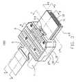
- FIG. 1is an exploded, perspective view of a cable assembly in accordance with the present invention
- FIG. 2is similar to FIG. 1 , but viewed from another aspect
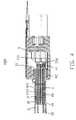
- FIG. 3is an assembled, perspective view of the cable assembly
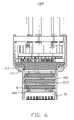
- FIG. 4is a cross-section view taken along line 4 - 4 of FIG. 3 ;
- FIG. 5is a cross-section view taken along line 5 - 5 of FIG. 3 ;
- FIG. 6is a cross-section view taken along line 6 - 6 of FIG. 3 ;
- FIG. 7is a cross-section view taken along line 7 - 7 of FIG. 3 ;
- FIG. 8is a cross-section view taken along line 8 - 8 of FIG. 3 .
- a cable assembly 1000 in accordance with the present inventioncomprises a housing 1 , a metallic plate 2 , a pair of printed circuit boards (PCBs) 31 , 32 , a spacer 4 , a latch mechanism 5 , a cap member 6 and four cables 7 .
- PCBsprinted circuit boards
- the housing 1having a first shield part 1 A and a second shield part 1 B together enclosing a receiving space 10 therein. Both the first shield part 1 A and the second shield part 1 B are made of metallic material and formed by die-cast process.
- the first shield part 1 Acomprises an expanded first base portion 11 and a relative slim first mating portion 12 extending forwardly from a front edge of the first base portion 11 .
- the first base portion 11has a top wall 111 , a pair of side walls 112 , 113 and a rear wall 114 together forming a hollow portion 110 .
- Four cavities 1141 , 1142are defined in a rear wall 114 and arranged in a row along transversal direction.
- the first mating portion 12has a top side 121 , a pair of transversal sides 122 , 123 corporately forming a mating port 120 located in front of and communicating with the hollow portion 110 .
- Two pair of first positioning cavities 1210are spaced apart each other and arranged at lateral sides of an inner side of the top side 121 .
- Three first positioning grooves 1212are defined in the top side 121 and disposed between the first positioning cavities 1210 .
- Two first retention members 1110are disposed in the hollow portion 110 and located at lateral sides of a front portion of the top wall 111 . Each first retention member 1110 further has a hole 1112 therein.
- the second shield part 1 Bcomprises a second base portion 13 and a second mating portion 14 extending forwardly from a front edge of the second base portion 13 .
- the second base portion 13has a bottom wall 131 , a pair of side walls 132 , 133 and a rear wall 134 extending upwardly from lateral edges and rear edge of the bottom wall 131 .
- Four cavities 1341 , 1342are defined in a rear wall 134 and arranged in a row along transversal direction.
- the four cavities 1141 , 1142 of the rear wall 114cooperating with corresponding cavities 1341 , 1342 of the rear wall 134 to form four cable exit outlets (not numbered).
- the cable exit outletsare separated into two groups and further staggered in a rear wall (not numbered) of the housing 1 .
- the first mating portion 14has a bottom side 141 , a pair of flanges 142 , 143 formed at lateral edges of the bottom side 141 .
- Two pair of second positioning cavities 1410are spaced apart each other and arranged at lateral sides of an inner side of the bottom side 141 .
- Two second positioning grooves 1412are defined in the bottom side 141 and disposed between the second positioning cavities 1410 .
- Two second retention members 1310located at lateral sides of an interior side of a front portion of the top wall 131 . Each second retention member 1310 further has a hole 1312 therein.
- the metal plate 2has a main portion 20 and a broader rear portion 22 connected to a rear end of the main portion 20 .
- Four through holes 202are arranged at lateral sides of the main portion 20 and spaced apart one another.
- Both the first and second PCBs 31 , 32includes middle portions 310 , 320 , narrower front portions 312 , 322 and broader rear portions 314 , 324 .
- the set of second conductive pads 3140are proximate left side of the rear portion 314 .
- a group of first conductive pads 3220are arranged on the front portion 322 to form a second mating interface and a set of second conductive pads 3240 arranged on the rear portion 324 to from a second mounting portion.
- the set of second conductive pads 3240are proximate right side of the rear portion 324 .
- the group of first conductive pads 3120 of the first PCB 31align with the group of first conductive pads 3220 of the second PCB 32 along a vertical direction, while the set of second conductive pads 3140 of the first PCB 31 offset the set of second conductive pads 3240 of the second PCB 32 along a vertical direction.
- Two pair of first conductive holes 3102are respectively defined in lateral sides of the middle portion 310 of the a first PCB 31
- two pair of second conductive holes 3202 aligning with the first conductive holes 3102are respectively defined in lateral sides of the middle portion 320 of the second PCB 32 .
- the first conductive holes 3102 and second conductive holes 3202are respectively connected to grounding traces (not shown) of the first PCB 31 and the second PCB 32 .
- the spacer 4is made of plastic or other insulative materials.
- the spacer 4has a body portion 40 , an engaging portion 42 attached to a back surface of the body portion 40 and a panel portion 41 extending rearward from a middle section of an end of the engaging portion 42 .
- Two passages 401 , 402are respectively defined in an upper portion and a lower portion of the body portion 40 and parallel to one another.
- a narrow groove 410is recessed forwardly from back surface of the panel portion 41 and disposed between the passages 401 , 402 .
- Three first bars 403 and two second bars 405are respectively formed on a top surface and a bottom surface of the body portion 40 and spaced apart from each other.
- a pair of pin holes 404pass through two of the first bars 403 and the two second bars 405 .
- Four first positioning members 406are arranged on the top surface of the body portion 40 and disposed outside of the first bars 403 .
- Four second positioning members 407are arranged on the bottom surface of the body portion 40 and respectively align with the first positioning members 406 along a vertical direction.
- a pair of first sunken portion 420 and a pair of second sunken portions 421are respectively defined in an up portion and a low portion of the engaging portion 42 . Either the first sunken portions 420 or the second sunken portions 421 has a tiny posts 422 , 423 therein.
- the first printed circuit board 31 and the second printed circuit board 32are respectively inserted into the passages 401 , 402 , with middle portions 310 , 320 received in the passages 401 , 402 of the body portion 40 , the front portions 312 , 322 extending beyond a front surface of the body portion 40 , and the rear portions 314 , 324 disposed outside of a back surface of the engaging portion 42 , without surpassing a back surface of the panel portion 41 .
- the metal plate 2is accommodated in the narrow groove 410 and insulated from the first and second printed circuit boards 31 , 32 .
- metal pins 8are inserted into pin holes 404 of the spacer 4 and pass through the first conductive holes 3102 , through holes 202 and second conductive holes 3202 to form a grounding line thereamong to reduce cross-talk between the first and second printed circuit boards 31 , 32 . Furthermore, the metal pins 8 also contact the first shield part 1 A. However, other metal rod/post is available for linking the metallic plate 2 , the first and second PCBs 31 , 32 and electrically contacting the housing 1 to form another grounding line.
- the cables 7includes separated into a first set cables 71 and second set cables 72 with identical structures.
- the first set cables 71 and second set cables 72have a number of wires 710 , 720 respectively soldered to the second conductive pads 3140 , 3240 of the first and second printed circuit boards 31 , 32 .
- the panel portion 41may prevent short-circuit problem between the mounting portions (soldering areas) of the first and second printed circuit boards 31 , 32 and the rear portion 22 of the metal plate 2 .
- Four cable holder members 712 , 722grip front segments of the first set cables 71 and second set cables 72 .
- the spacer 4is mounted to the first shield part 1 A, with the body portion 40 received in the mating port 120 , the engaging portion 42 received in the hollow portion 110 , the first bars 403 located in the first positioning grooves 1212 , the first positioning members 406 located in the first positioning cavities 1210 , the first retention members 1110 disposed in the first sunken portions 420 , the tiny posts 422 inserted into the holes 1112 of the first retention members 1110 , the cable holder members 712 , 712 accommodated in the cavities 1141 , 1142 of the rear wall 114 .
- the second shield part 1 Bis mounted to the first shield part 1 A, with the second bars 405 received in the second positioning grooves 1412 , the second positioning members 407 received in the second positioning cavities 1410 , the second retention members 1310 located in the second sunken portions 421 , the tiny posts 421 inserted into the holes 1312 of the second retention members 1310 .
- Four screw members 9are utilized to keep the first shield part 1 A and the second shield part 1 B together.
- the latch mechanism 5is assembled to first shield part 1 A of the housing 1 .
- the latch mechanism 5includes a latch member 51 , an actuator 52 and a pull tape 53 attached to a rear portion of the actuator 52 .
- the latch member 51has a latch portion 511 disposed above first mating portion 12 of the housing 1 .
- the actuator 52is partially shielded by cap member 5 .
Landscapes
- Engineering & Computer Science (AREA)
- Microelectronics & Electronic Packaging (AREA)
- Coupling Device And Connection With Printed Circuit (AREA)
- Shielding Devices Or Components To Electric Or Magnetic Fields (AREA)
Abstract
Description
The present invention generally relates to a cable assembly, and more particularly to a cable assembly having an improved structure for suppressing cross-talk to acquire better signal transmission property.
PCI Express, officially abbreviated as PCI-E or PCIe, is a computer expansion card interface format introduced by Intel in 2004. It was designed to replace the general-purpose PCI expansion bus, the high-end PCI-X bus and the AGP graphics card interface. Unlike previous PC expansion interfaces, rather than being merely a bus, it is configured around point-to-point full duplex serial links called lanes. In PCIe 1.1 (the most common version as of 2007) each lane carries 250 MB/s in each direction.
PCI Express External Cabling which extends the PCI Express interconnects architecture “outside the box.” Cables using the PCIe technology will be used for external applications, as well as applications internal to an enclosure that need a cable connection. PCI Express External Cabling Specification, REV. 1.0 introduced four kinds of cable assemblies x1, x4, x8 and x16, and among which the x16 cable assembly may reach highest transmitting rate. The x16 cable assembly includes a housing, a pair of stacked PCBs accommodated in a space of the housing and four cables terminated to corresponding the PCBs. However, when signals are transmitted via the pair of stacked PCBs, cross-talk phenomena therebetween may have negative effect on electrical property of a signal transmitting line.
Hence, an improved cable assembly is highly desired to overcome the aforementioned problems.
Accordingly, an object of the present invention is to provide a cable assembly having an improved structure that can reduce cross-talk around a mating interface thereof.
In order to achieve the object set forth, a cable assembly in accordance with the present invention comprises a housing has a receiving space, said receiving space including a hollow portion and a mating port located in front of the hollow portion; a spacer located in the receiving space; a first and second printed circuit boards partially enclosed within the spacer and arranged apart from one another, both the first and second printed circuit boards having mating interfaces extending into the mating port and mounting portions disposed in the hollow portion; a metallic plate assembled to the spacer and disposed between the pair of first and second printed circuit boards; a plurality of cables coupled to the mounting portions of the pair of first and second printed circuit boards, respectively.
Other objects, advantages and novel features of the invention will become more apparent from the following detailed description when taken in conjunction with the accompanying drawings.
Reference will now be made in detail to the preferred embodiment of the present invention.
Referring toFIGS. 1-3 and in conjunction withFIGS. 4-9 , acable assembly 1000 in accordance with the present invention comprises ahousing 1, ametallic plate 2, a pair of printed circuit boards (PCBs)31,32, aspacer 4, alatch mechanism 5, acap member 6 and fourcables 7.
Thehousing 1 having afirst shield part 1A and asecond shield part 1B together enclosing areceiving space 10 therein. Both thefirst shield part 1A and thesecond shield part 1B are made of metallic material and formed by die-cast process.
Thefirst shield part 1A comprises an expandedfirst base portion 11 and a relative slimfirst mating portion 12 extending forwardly from a front edge of thefirst base portion 11. Thefirst base portion 11 has atop wall 111, a pair ofside walls rear wall 114 together forming ahollow portion 110. Fourcavities rear wall 114 and arranged in a row along transversal direction. Thefirst mating portion 12 has atop side 121, a pair oftransversal sides mating port 120 located in front of and communicating with thehollow portion 110. Two pair offirst positioning cavities 1210 are spaced apart each other and arranged at lateral sides of an inner side of thetop side 121. Threefirst positioning grooves 1212 are defined in thetop side 121 and disposed between thefirst positioning cavities 1210. Twofirst retention members 1110 are disposed in thehollow portion 110 and located at lateral sides of a front portion of thetop wall 111. Eachfirst retention member 1110 further has ahole 1112 therein.
Thesecond shield part 1B comprises asecond base portion 13 and asecond mating portion 14 extending forwardly from a front edge of thesecond base portion 13. Thesecond base portion 13 has abottom wall 131, a pair ofside walls rear wall 134 extending upwardly from lateral edges and rear edge of thebottom wall 131. Fourcavities rear wall 134 and arranged in a row along transversal direction. The fourcavities rear wall 114 cooperating withcorresponding cavities rear wall 134 to form four cable exit outlets (not numbered). The cable exit outlets are separated into two groups and further staggered in a rear wall (not numbered) of thehousing 1. Thefirst mating portion 14 has abottom side 141, a pair offlanges bottom side 141. Two pair ofsecond positioning cavities 1410 are spaced apart each other and arranged at lateral sides of an inner side of thebottom side 141. Twosecond positioning grooves 1412 are defined in thebottom side 141 and disposed between thesecond positioning cavities 1410. Twosecond retention members 1310 located at lateral sides of an interior side of a front portion of thetop wall 131. Eachsecond retention member 1310 further has ahole 1312 therein.
Themetal plate 2 has amain portion 20 and a broaderrear portion 22 connected to a rear end of themain portion 20. Four throughholes 202 are arranged at lateral sides of themain portion 20 and spaced apart one another.
Both the first andsecond PCBs middle portions front portions rear portions conductive pads 3120 arranged on thefront portion 312 to form a first mating interface and a set of secondconductive pads 3140 arranged on therear portion 314 to from a first mounting portion. The set of secondconductive pads 3140 are proximate left side of therear portion 314. Similarly, a group of firstconductive pads 3220 are arranged on thefront portion 322 to form a second mating interface and a set of secondconductive pads 3240 arranged on therear portion 324 to from a second mounting portion. The set of secondconductive pads 3240 are proximate right side of therear portion 324. When the first andsecond PCBs space 10 of thehousing 1, the group of firstconductive pads 3120 of thefirst PCB 31 align with the group of firstconductive pads 3220 of thesecond PCB 32 along a vertical direction, while the set of secondconductive pads 3140 of thefirst PCB 31 offset the set of secondconductive pads 3240 of thesecond PCB 32 along a vertical direction. Two pair of firstconductive holes 3102 are respectively defined in lateral sides of themiddle portion 310 of the afirst PCB 31, and two pair of secondconductive holes 3202 aligning with the firstconductive holes 3102 are respectively defined in lateral sides of themiddle portion 320 of thesecond PCB 32. The firstconductive holes 3102 and secondconductive holes 3202 are respectively connected to grounding traces (not shown) of thefirst PCB 31 and thesecond PCB 32.
Thespacer 4 is made of plastic or other insulative materials. Thespacer 4 has abody portion 40, anengaging portion 42 attached to a back surface of thebody portion 40 and apanel portion 41 extending rearward from a middle section of an end of theengaging portion 42. Twopassages body portion 40 and parallel to one another. Anarrow groove 410 is recessed forwardly from back surface of thepanel portion 41 and disposed between thepassages first bars 403 and twosecond bars 405 are respectively formed on a top surface and a bottom surface of thebody portion 40 and spaced apart from each other. A pair of pin holes404 pass through two of thefirst bars 403 and the twosecond bars 405. Fourfirst positioning members 406 are arranged on the top surface of thebody portion 40 and disposed outside of the first bars403. Foursecond positioning members 407 are arranged on the bottom surface of thebody portion 40 and respectively align with thefirst positioning members 406 along a vertical direction. A pair of firstsunken portion 420 and a pair of secondsunken portions 421 are respectively defined in an up portion and a low portion of the engagingportion 42. Either the firstsunken portions 420 or the secondsunken portions 421 has atiny posts
The first printedcircuit board 31 and the second printedcircuit board 32 are respectively inserted into thepassages middle portions passages body portion 40, thefront portions body portion 40, and therear portions portion 42, without surpassing a back surface of thepanel portion 41. Themetal plate 2 is accommodated in thenarrow groove 410 and insulated from the first and second printedcircuit boards metal pins 8 are inserted intopin holes 404 of thespacer 4 and pass through the firstconductive holes 3102, throughholes 202 and secondconductive holes 3202 to form a grounding line thereamong to reduce cross-talk between the first and second printedcircuit boards metal pins 8 also contact thefirst shield part 1A. However, other metal rod/post is available for linking themetallic plate 2, the first andsecond PCBs housing 1 to form another grounding line.
Thecables 7 includes separated into afirst set cables 71 andsecond set cables 72 with identical structures. Thefirst set cables 71 andsecond set cables 72 have a number ofwires conductive pads circuit boards panel portion 41 may prevent short-circuit problem between the mounting portions (soldering areas) of the first and second printedcircuit boards rear portion 22 of themetal plate 2. Fourcable holder members first set cables 71 andsecond set cables 72.
Thespacer 4 is mounted to thefirst shield part 1A, with thebody portion 40 received in themating port 120, the engagingportion 42 received in thehollow portion 110, thefirst bars 403 located in thefirst positioning grooves 1212, thefirst positioning members 406 located in thefirst positioning cavities 1210, thefirst retention members 1110 disposed in the firstsunken portions 420, thetiny posts 422 inserted into theholes 1112 of thefirst retention members 1110, thecable holder members cavities rear wall 114. Thesecond shield part 1B is mounted to thefirst shield part 1A, with thesecond bars 405 received in thesecond positioning grooves 1412, thesecond positioning members 407 received in thesecond positioning cavities 1410, thesecond retention members 1310 located in the secondsunken portions 421, thetiny posts 421 inserted into theholes 1312 of thesecond retention members 1310. Fourscrew members 9 are utilized to keep thefirst shield part 1A and thesecond shield part 1B together.
Anoptional latch mechanism 5 is assembled tofirst shield part 1A of thehousing 1. Thelatch mechanism 5 includes alatch member 51, anactuator 52 and apull tape 53 attached to a rear portion of theactuator 52. Thelatch member 51 has alatch portion 511 disposed abovefirst mating portion 12 of thehousing 1. Theactuator 52 is partially shielded bycap member 5.
It will be understood that the invention may be embodied in other specific forms without departing from the spirit or central characteristics thereof. The present examples and embodiments, therefore, are to be considered in all respects as illustrative and not restrictive, and the invention is not to be limited to the details given herein.
Claims (17)
1. A cable assembly, comprising:
a housing has a receiving space, said receiving space including a hollow portion and a mating port located in front of the hollow portion;
a spacer located in the receiving space;
a first and second printed circuit boards partially enclosed within the spacer and arranged apart from one another, both the first and second printed circuit boards having mating interfaces extending into the mating port and mounting portions disposed in the hollow portion;
a metallic plate assembled to the spacer and disposed between the pair of first and second printed circuit boards;
a plurality of cables coupled to the mounting portions of the pair of first and second printed circuit boards, respectively.
2. The cable assembly as recited inclaim 1 , wherein at least a conductive hole is defined in each of the first and second printed circuit boards, wherein a through hole is defined in the metallic plate and a metal pin member is inserted through the through hole of the metallic plate and the conductive holes of the first and second printed circuit boards.
3. The cable assembly as recited inclaim 1 , wherein at least a bar is formed on a top surface or a bottom surface of the spacer, wherein corresponding positioning groove is defined in an interior side of a mating portion of the housing.
4. The cable assembly as recited inclaim 1 , wherein a pair of passages are respectively defined in an upper portion and a lower portion of the spacer to receive the first and second printed circuit boards.
5. The cable assembly as recited inclaim 4 , wherein the pair of passages are parallel to each other.
6. The cable assembly as recited inclaim 4 , wherein a groove is defined in the spacer and disposed between the passages to receiving the metallic plate.
7. The cable assembly as recited inclaim 1 , wherein mounting portions of the first and second printed circuit boards extending beyond back face of the spacer and a panel portion is formed on a back face of the spacer and disposed between the mounting portions of the first and second printed circuit boards.
8. The cable assembly as recited inclaim 7 , wherein the metallic plate is assembled to the spacer via a groove in the panel portion.
9. A cable assembly, comprising:
a metallic housing including a first shield part assembled to a second shield part to form a receiving space, said receiving space including a hollow portion and a mating port located in front of the hollow portion;
a first printed circuit board parallel to a second printed circuit board and enclosed within the receiving space, said first and the second printed circuit boards having mating interfaces extending into the mating port and mounting portions located in the hollow portion;
a metallic plate disposed between the first and second printed circuit boards, said metallic plate electrically connected to the metallic housing via at least a metallic pin; and
a plurality of wires connected to the mounting portions of the first and second printed circuit boards; wherein the metallic plate is enclosed in a spacer and insulated from the first and second printed circuit boards.
10. The cable assembly as recited inclaim 9 , wherein the metallic pin member are further inserted through conductive holes of the first and second printed circuit boards.
11. The cable assembly as recited inclaim 9 , wherein the metallic plate is located at a middle section between the first and second printed circuit boards.
12. The cable assembly as recited inclaim 9 , wherein the metallic plate is parallel to the first and second printed circuit boards.
13. The cable assembly as recited inclaim 9 , wherein the spacer has a body portion and an engaging portion joining to the body portion, wherein the body portion and the engaging portion respectively received in the mating port and hollow portion of the metallic housing.
14. The cable assembly as recited inclaim 13 , wherein the body portion and the engaging portion engage with the metallic housing via retaining means.
15. The cable assembly as recited inclaim 13 , wherein a panel portion extends rearward from back surface of the engaging portion of the spacer and located between the mounting portions of the first and second printed circuit boards.
16. The cable assembly as recited inclaim 15 , wherein the metallic plate is inserted into the spacer via a groove recessed forwardly from a back face of the panel portion.
17. A cable connector assembly comprising:
a casing defining a receiving cavity;
vertically aligned upper and lower printed circuit boards respectively located at upper and lower levels while commonly received in the receiving cavity in a parallel relation with each other;
upper and lower cables offset from each other vertically to be located at the upper and the lower levels, respectively, and further offset from each other horizontally to connect to different positions of the corresponding upper and lower printed circuit boards in a transverse direction so as to have the whole assembly in a dense arrangement without interference; wherein a grounding plate is located between the upper printed circuit board and the lower printed circuit board; wherein each of said upper cable and lower cables have corresponding wires respectively mounted to opposite upper and lower surfaces of each of the upper and lower printed circuit boards.
Priority Applications (2)
| Application Number | Priority Date | Filing Date | Title |
|---|---|---|---|
| US12/218,862US7654831B1 (en) | 2008-07-18 | 2008-07-18 | Cable assembly having improved configuration for suppressing cross-talk |
| CN2009201609990UCN201498627U (en) | 2008-07-18 | 2009-07-17 | Cable Connector Assembly |
Applications Claiming Priority (1)
| Application Number | Priority Date | Filing Date | Title |
|---|---|---|---|
| US12/218,862US7654831B1 (en) | 2008-07-18 | 2008-07-18 | Cable assembly having improved configuration for suppressing cross-talk |
Publications (2)
| Publication Number | Publication Date |
|---|---|
| US20100015851A1 US20100015851A1 (en) | 2010-01-21 |
| US7654831B1true US7654831B1 (en) | 2010-02-02 |
Family
ID=41530685
Family Applications (1)
| Application Number | Title | Priority Date | Filing Date |
|---|---|---|---|
| US12/218,862Expired - Fee RelatedUS7654831B1 (en) | 2008-07-18 | 2008-07-18 | Cable assembly having improved configuration for suppressing cross-talk |
Country Status (2)
| Country | Link |
|---|---|
| US (1) | US7654831B1 (en) |
| CN (1) | CN201498627U (en) |
Cited By (58)
| Publication number | Priority date | Publication date | Assignee | Title |
|---|---|---|---|---|
| US20090301761A1 (en)* | 2008-06-09 | 2009-12-10 | Hon Hai Precision Ind. Co., Ltd. | Cable assembly having connector with interior printed circuit board facilitating termination |
| US20100248544A1 (en)* | 2009-03-26 | 2010-09-30 | Hon Hai Precision Industry Co., Ltd. | Cable assembly wth emi protection |
| US20110086548A1 (en)* | 2009-10-13 | 2011-04-14 | Hon Hai Precision Industry Co., Ltd. | Cable assembly with one cable coupled to dual interfaces and methode of making the same |
| US20110300749A1 (en)* | 2009-01-20 | 2011-12-08 | Molex Incorporated | Plug Connector With External EMI Shielding Capability |
| US20120040551A1 (en)* | 2010-08-10 | 2012-02-16 | Hon Hai Precision Industry Co., Ltd. | Electrical connector assembly with a latch mechanism easily operated |
| US20120040550A1 (en)* | 2010-08-10 | 2012-02-16 | Hon Hai Precision Industry Co., Ltd. | Electrical connector assembly with a latch mechanism easily operated |
| US20120040552A1 (en)* | 2010-08-10 | 2012-02-16 | Hon Hai Precision Industry Co., Ltd. | Electrical connector assembly |
| US20120045920A1 (en)* | 2010-08-18 | 2012-02-23 | Hon Hai Precision Industry Co., Ltd. | Cable assembly with a new interface |
| US20120064779A1 (en)* | 2010-09-15 | 2012-03-15 | Hon Hai Precision Industry Co., Ltd. | Cable assembly with lower profile interface |
| US8235731B1 (en)* | 2011-03-18 | 2012-08-07 | Leviton Manufacturing Co., Ltd. | Connector module and patch panel |
| US20120214324A1 (en)* | 2011-02-18 | 2012-08-23 | Hon Hai Precision Industry Co., Ltd. | Electrical connector assembly with external metallic gasket |
| US20120214350A1 (en)* | 2011-02-18 | 2012-08-23 | Hon Hai Precision Industry Co., Ltd. | Electrical connector assembly having two spaced internal printed circuit boards and an external metallic gasket |
| US20120214345A1 (en)* | 2011-02-18 | 2012-08-23 | Hon Hai Precision Industry Co., Ltd. | Electrical connector assembly having an improved emi gasket |
| US20130231011A1 (en)* | 2010-03-19 | 2013-09-05 | Molex Incorporated | Plug connector with improved construction |
| US20130316561A1 (en)* | 2012-05-25 | 2013-11-28 | Weetech Gmbh | Variable plug of a connector |
| US20140041937A1 (en)* | 2009-01-30 | 2014-02-13 | Brian Keith Lloyd | High Speed Bypass Cable Assembly |
| US20150038004A1 (en)* | 2013-08-01 | 2015-02-05 | Hon Hai Precision Industry Co., Ltd. | Cable connector assembly having simple wiring arrangement between two end connectors |
| US8974251B2 (en)* | 2012-06-16 | 2015-03-10 | Hon Hai Precision Industry Co., Ltd. | Electrical connector assembly and method of manufacturing the same |
| US9142921B2 (en) | 2013-02-27 | 2015-09-22 | Molex Incorporated | High speed bypass cable for use with backplanes |
| US9147977B2 (en) | 2012-07-05 | 2015-09-29 | Leviton Manufacturing Co., Inc. | High density high speed data communications connector |
| US20160043517A1 (en)* | 2014-08-07 | 2016-02-11 | Foxconn Interconnect Technology Limited | Cable connector assembly with simple arrangement of core wires |
| US20160043510A1 (en)* | 2014-06-27 | 2016-02-11 | Shenzhen Deren Electronic Co., Ltd | Plug connector, receptacle connector, and electric connector assembly thereof |
| US20160093985A1 (en)* | 2013-02-20 | 2016-03-31 | Foxconn Interconnect Technology Limited | High speed high density connector assembly |
| US20160197443A1 (en)* | 2015-01-06 | 2016-07-07 | Molex, Llc | Electrical connector |
| US20170288343A1 (en)* | 2014-05-08 | 2017-10-05 | Apple Inc. | Connector system impedance matching |
| US9847607B2 (en) | 2014-04-23 | 2017-12-19 | Commscope Technologies Llc | Electrical connector with shield cap and shielded terminals |
| US20180115114A1 (en)* | 2015-04-29 | 2018-04-26 | Hewlett Packard Enterprise Development Lp | Cable Assembly |
| US10062984B2 (en) | 2013-09-04 | 2018-08-28 | Molex, Llc | Connector system with cable by-pass |
| US10103494B2 (en) | 2014-05-08 | 2018-10-16 | Apple Inc. | Connector system impedance matching |
| US10135211B2 (en) | 2015-01-11 | 2018-11-20 | Molex, Llc | Circuit board bypass assemblies and components therefor |
| US10367280B2 (en) | 2015-01-11 | 2019-07-30 | Molex, Llc | Wire to board connectors suitable for use in bypass routing assemblies |
| US10424856B2 (en) | 2016-01-11 | 2019-09-24 | Molex, Llc | Routing assembly and system using same |
| US10424878B2 (en) | 2016-01-11 | 2019-09-24 | Molex, Llc | Cable connector assembly |
| US10522958B2 (en) | 2014-09-26 | 2019-12-31 | Hewlett Packard Enterprise Development Lp | Receptacle for connecting a multi-lane or one-lane cable |
| US10720735B2 (en) | 2016-10-19 | 2020-07-21 | Amphenol Corporation | Compliant shield for very high speed, high density electrical interconnection |
| US10741963B2 (en) | 2015-02-27 | 2020-08-11 | Hewlett Packard Enterprise Development Lp | Cable assembly with conjoined one-lane cable assemblies |
| US10739828B2 (en) | 2015-05-04 | 2020-08-11 | Molex, Llc | Computing device using bypass assembly |
| US10833437B2 (en)* | 2018-05-30 | 2020-11-10 | Dongguan Luxshare Technologies Co., Ltd | High-speed connector on high-density mini version chip side |
| US10840649B2 (en) | 2014-11-12 | 2020-11-17 | Amphenol Corporation | Organizer for a very high speed, high density electrical interconnection system |
| US10931062B2 (en) | 2018-11-21 | 2021-02-23 | Amphenol Corporation | High-frequency electrical connector |
| US10999948B2 (en)* | 2019-09-06 | 2021-05-04 | Inventec (Pudong) Technology Corporation | Electronic device and supporting member thereof |
| US11070006B2 (en) | 2017-08-03 | 2021-07-20 | Amphenol Corporation | Connector for low loss interconnection system |
| US11101611B2 (en) | 2019-01-25 | 2021-08-24 | Fci Usa Llc | I/O connector configured for cabled connection to the midboard |
| US11151300B2 (en) | 2016-01-19 | 2021-10-19 | Molex, Llc | Integrated routing assembly and system using same |
| US11189943B2 (en) | 2019-01-25 | 2021-11-30 | Fci Usa Llc | I/O connector configured for cable connection to a midboard |
| US11205877B2 (en) | 2018-04-02 | 2021-12-21 | Ardent Concepts, Inc. | Controlled-impedance compliant cable termination |
| US20220021137A1 (en)* | 2020-07-20 | 2022-01-20 | TE Connectivity Services Gmbh | Dual circuit card pluggable module |
| US20220167493A1 (en)* | 2019-04-03 | 2022-05-26 | I-Pex Inc. | Connector and Method for Manufacturing Same |
| US11437762B2 (en) | 2019-02-22 | 2022-09-06 | Amphenol Corporation | High performance cable connector assembly |
| US11444398B2 (en) | 2018-03-22 | 2022-09-13 | Amphenol Corporation | High density electrical connector |
| US11469553B2 (en) | 2020-01-27 | 2022-10-11 | Fci Usa Llc | High speed connector |
| US11522310B2 (en) | 2012-08-22 | 2022-12-06 | Amphenol Corporation | High-frequency electrical connector |
| US11670879B2 (en) | 2020-01-28 | 2023-06-06 | Fci Usa Llc | High frequency midboard connector |
| US11735852B2 (en) | 2019-09-19 | 2023-08-22 | Amphenol Corporation | High speed electronic system with midboard cable connector |
| USD1002553S1 (en) | 2021-11-03 | 2023-10-24 | Amphenol Corporation | Gasket for connector |
| US11799246B2 (en) | 2020-01-27 | 2023-10-24 | Fci Usa Llc | High speed connector |
| US11811163B2 (en) | 2021-02-26 | 2023-11-07 | Leviton Manufacturing Co., Inc. | Mutoa and quad floating connector |
| US11831106B2 (en) | 2016-05-31 | 2023-11-28 | Amphenol Corporation | High performance cable termination |
Families Citing this family (17)
| Publication number | Priority date | Publication date | Assignee | Title |
|---|---|---|---|---|
| US7909632B2 (en)* | 2009-03-13 | 2011-03-22 | Hon Hai Precision Ind. Co., Ltd. | Cable assembly with latching mechanism |
| US8052481B2 (en)* | 2009-04-30 | 2011-11-08 | J.S.T. Corporation | Electrical connector receptacle |
| CN201638994U (en)* | 2010-02-09 | 2010-11-17 | 富士康(昆山)电脑接插件有限公司 | Cable Connector Assembly |
| JP5620721B2 (en)* | 2010-06-18 | 2014-11-05 | シロキ工業株式会社 | Vehicle door frame and manufacturing method thereof |
| US8979553B2 (en)* | 2012-10-25 | 2015-03-17 | Molex Incorporated | Connector guide for orienting wires for termination |
| US9484681B2 (en) | 2013-07-19 | 2016-11-01 | Foxconn Interconnect Technology Limited | Flippable electrical connector |
| US9905944B2 (en) | 2013-07-19 | 2018-02-27 | Foxconn Interconnect Technology Limited | Flippable electrical connector |
| US10693261B2 (en) | 2013-07-19 | 2020-06-23 | Foxconn Interconnect Technology Limited | Flippable electrical connector |
| US10720734B2 (en) | 2013-07-19 | 2020-07-21 | Foxconn Interconnect Technology Limited | Flippable electrical connector |
| US9997853B2 (en) | 2013-07-19 | 2018-06-12 | Foxconn Interconnect Technology Limited | Flippable electrical connector |
| US10170870B2 (en) | 2013-07-19 | 2019-01-01 | Foxconn Interconnect Technology Limited | Flippable electrical connector |
| US10826255B2 (en) | 2013-07-19 | 2020-11-03 | Foxconn Interconnect Technology Limited | Flippable electrical connector |
| US9912111B2 (en) | 2013-07-19 | 2018-03-06 | Foxconn Interconnect Technology Limited | Flippable electrical connector |
| US9843148B2 (en) | 2013-07-19 | 2017-12-12 | Foxconn Interconnect Technology Limited | Flippable electrical connector |
| CN107910711B (en)* | 2014-07-04 | 2019-08-30 | 富士康(昆山)电脑接插件有限公司 | Socket connector |
| CN105470714A (en)* | 2014-09-03 | 2016-04-06 | 凡甲电子(苏州)有限公司 | Electric connector |
| CN104241975B (en)* | 2014-09-04 | 2017-06-06 | 深圳市正耀科技有限公司 | A kind of connector plug, connector body and its connector combination |
Citations (7)
| Publication number | Priority date | Publication date | Assignee | Title |
|---|---|---|---|---|
| US5219294A (en) | 1991-02-20 | 1993-06-15 | Amp Incorporated | Electrical docking connector |
| US5873743A (en)* | 1997-03-14 | 1999-02-23 | International Business Machines Corporation | High-density and high-speed cable assembly |
| US6699073B1 (en)* | 2002-10-22 | 2004-03-02 | Hon Hai Precision Ind. Co., Ltd. | Cable assembly |
| US6739910B1 (en)* | 2003-07-11 | 2004-05-25 | Hon Hai Precision Ind. Co., Ltd. | Cable assembly with internal circuit modules |
| US6865369B2 (en)* | 1999-11-10 | 2005-03-08 | Fci | Receptacle and plug connectors |
| US6899566B2 (en)* | 2002-01-28 | 2005-05-31 | Erni Elektroapparate Gmbh | Connector assembly interface for L-shaped ground shields and differential contact pairs |
| US7134914B1 (en) | 2005-08-11 | 2006-11-14 | Hon Hai Precision Ind. Co., Ltd. | Cable connector assembly with latching mechanism |
- 2008
- 2008-07-18USUS12/218,862patent/US7654831B1/ennot_activeExpired - Fee Related
- 2009
- 2009-07-17CNCN2009201609990Upatent/CN201498627U/ennot_activeExpired - Fee Related
Patent Citations (7)
| Publication number | Priority date | Publication date | Assignee | Title |
|---|---|---|---|---|
| US5219294A (en) | 1991-02-20 | 1993-06-15 | Amp Incorporated | Electrical docking connector |
| US5873743A (en)* | 1997-03-14 | 1999-02-23 | International Business Machines Corporation | High-density and high-speed cable assembly |
| US6865369B2 (en)* | 1999-11-10 | 2005-03-08 | Fci | Receptacle and plug connectors |
| US6899566B2 (en)* | 2002-01-28 | 2005-05-31 | Erni Elektroapparate Gmbh | Connector assembly interface for L-shaped ground shields and differential contact pairs |
| US6699073B1 (en)* | 2002-10-22 | 2004-03-02 | Hon Hai Precision Ind. Co., Ltd. | Cable assembly |
| US6739910B1 (en)* | 2003-07-11 | 2004-05-25 | Hon Hai Precision Ind. Co., Ltd. | Cable assembly with internal circuit modules |
| US7134914B1 (en) | 2005-08-11 | 2006-11-14 | Hon Hai Precision Ind. Co., Ltd. | Cable connector assembly with latching mechanism |
Cited By (125)
| Publication number | Priority date | Publication date | Assignee | Title |
|---|---|---|---|---|
| US8052430B2 (en)* | 2008-06-09 | 2011-11-08 | Hon Hai Precision Ind. Co., Ltd. | Cable assembly having connector with interior printed circuit board facilitating termination |
| US20090301761A1 (en)* | 2008-06-09 | 2009-12-10 | Hon Hai Precision Ind. Co., Ltd. | Cable assembly having connector with interior printed circuit board facilitating termination |
| US20110300749A1 (en)* | 2009-01-20 | 2011-12-08 | Molex Incorporated | Plug Connector With External EMI Shielding Capability |
| US8439706B2 (en)* | 2009-01-20 | 2013-05-14 | Molex Incorporated | Plug connector with external EMI shielding capability |
| US9011177B2 (en)* | 2009-01-30 | 2015-04-21 | Molex Incorporated | High speed bypass cable assembly |
| US20140041937A1 (en)* | 2009-01-30 | 2014-02-13 | Brian Keith Lloyd | High Speed Bypass Cable Assembly |
| USRE48230E1 (en)* | 2009-01-30 | 2020-09-29 | Molex, Llc | High speed bypass cable assembly |
| USRE47342E1 (en)* | 2009-01-30 | 2019-04-09 | Molex, Llc | High speed bypass cable assembly |
| US20100248544A1 (en)* | 2009-03-26 | 2010-09-30 | Hon Hai Precision Industry Co., Ltd. | Cable assembly wth emi protection |
| US7997909B2 (en)* | 2009-03-26 | 2011-08-16 | Hon Hai Precision Ind. Co., Ltd. | Cable assembly wth EMI protection |
| US8303314B2 (en)* | 2009-10-13 | 2012-11-06 | Hon Hai Precision Ind. Co., Ltd. | Cable assembly with one cable coupled to dual interfaces and methode of making the same |
| US20110086548A1 (en)* | 2009-10-13 | 2011-04-14 | Hon Hai Precision Industry Co., Ltd. | Cable assembly with one cable coupled to dual interfaces and methode of making the same |
| US8770990B2 (en)* | 2010-03-19 | 2014-07-08 | Molex Incorporated | Plug connector with improved construction |
| US20130231011A1 (en)* | 2010-03-19 | 2013-09-05 | Molex Incorporated | Plug connector with improved construction |
| US20120040552A1 (en)* | 2010-08-10 | 2012-02-16 | Hon Hai Precision Industry Co., Ltd. | Electrical connector assembly |
| US20120040550A1 (en)* | 2010-08-10 | 2012-02-16 | Hon Hai Precision Industry Co., Ltd. | Electrical connector assembly with a latch mechanism easily operated |
| US8360799B2 (en)* | 2010-08-10 | 2013-01-29 | Hon Hai Precision Ind. Co., Ltd. | Electrical connector assembly |
| US20120040551A1 (en)* | 2010-08-10 | 2012-02-16 | Hon Hai Precision Industry Co., Ltd. | Electrical connector assembly with a latch mechanism easily operated |
| US20120045920A1 (en)* | 2010-08-18 | 2012-02-23 | Hon Hai Precision Industry Co., Ltd. | Cable assembly with a new interface |
| US8562369B2 (en)* | 2010-08-18 | 2013-10-22 | Hon Hai Precision Industry Co., Ltd. | Cable assembly with a new interface |
| US20120064779A1 (en)* | 2010-09-15 | 2012-03-15 | Hon Hai Precision Industry Co., Ltd. | Cable assembly with lower profile interface |
| US8708752B2 (en)* | 2010-09-15 | 2014-04-29 | Hon Hai Precision Industry Co., Ltd. | Cable assembly with lower profile interface |
| US20120214345A1 (en)* | 2011-02-18 | 2012-08-23 | Hon Hai Precision Industry Co., Ltd. | Electrical connector assembly having an improved emi gasket |
| US8550848B2 (en)* | 2011-02-18 | 2013-10-08 | Hon Hai Precision Industry Co., Ltd. | Electrical connector assembly having an improved EMI gasket |
| US8506331B2 (en)* | 2011-02-18 | 2013-08-13 | Hon Hai Precision Industry Co., Ltd. | Electrical connector assembly with external metallic gasket |
| US8480432B2 (en)* | 2011-02-18 | 2013-07-09 | Hon Hai Precision Industry Co., Ltd. | Electrical connector assembly having two spaced internal printed circuit boards and an external metallic gasket |
| US20120214350A1 (en)* | 2011-02-18 | 2012-08-23 | Hon Hai Precision Industry Co., Ltd. | Electrical connector assembly having two spaced internal printed circuit boards and an external metallic gasket |
| US20120214324A1 (en)* | 2011-02-18 | 2012-08-23 | Hon Hai Precision Industry Co., Ltd. | Electrical connector assembly with external metallic gasket |
| US8235731B1 (en)* | 2011-03-18 | 2012-08-07 | Leviton Manufacturing Co., Ltd. | Connector module and patch panel |
| US20130316561A1 (en)* | 2012-05-25 | 2013-11-28 | Weetech Gmbh | Variable plug of a connector |
| US9065193B2 (en)* | 2012-05-25 | 2015-06-23 | Weetech Gmbh | Variable plug of a connector |
| US8974251B2 (en)* | 2012-06-16 | 2015-03-10 | Hon Hai Precision Industry Co., Ltd. | Electrical connector assembly and method of manufacturing the same |
| US9147977B2 (en) | 2012-07-05 | 2015-09-29 | Leviton Manufacturing Co., Inc. | High density high speed data communications connector |
| US11522310B2 (en) | 2012-08-22 | 2022-12-06 | Amphenol Corporation | High-frequency electrical connector |
| US11901663B2 (en) | 2012-08-22 | 2024-02-13 | Amphenol Corporation | High-frequency electrical connector |
| US20160093985A1 (en)* | 2013-02-20 | 2016-03-31 | Foxconn Interconnect Technology Limited | High speed high density connector assembly |
| US9362678B2 (en) | 2013-02-27 | 2016-06-07 | Molex, Llc | Connection system for use with a chip |
| US10069225B2 (en) | 2013-02-27 | 2018-09-04 | Molex, Llc | High speed bypass cable for use with backplanes |
| US10305204B2 (en) | 2013-02-27 | 2019-05-28 | Molex, Llc | High speed bypass cable for use with backplanes |
| US9257794B2 (en) | 2013-02-27 | 2016-02-09 | Molex, Llc | High speed bypass cable for use with backplanes |
| US10056706B2 (en) | 2013-02-27 | 2018-08-21 | Molex, Llc | High speed bypass cable for use with backplanes |
| US9490558B2 (en) | 2013-02-27 | 2016-11-08 | Molex, Llc | Connection system for use with a chip |
| US9985367B2 (en) | 2013-02-27 | 2018-05-29 | Molex, Llc | High speed bypass cable for use with backplanes |
| US9608348B2 (en) | 2013-02-27 | 2017-03-28 | Molex, Llc | High speed bypass cable for use with backplanes |
| US9142921B2 (en) | 2013-02-27 | 2015-09-22 | Molex Incorporated | High speed bypass cable for use with backplanes |
| US20150038004A1 (en)* | 2013-08-01 | 2015-02-05 | Hon Hai Precision Industry Co., Ltd. | Cable connector assembly having simple wiring arrangement between two end connectors |
| US9203171B2 (en)* | 2013-08-01 | 2015-12-01 | Hon Hai Precision Industry Co., Ltd. | Cable connector assembly having simple wiring arrangement between two end connectors |
| US10062984B2 (en) | 2013-09-04 | 2018-08-28 | Molex, Llc | Connector system with cable by-pass |
| US10181663B2 (en) | 2013-09-04 | 2019-01-15 | Molex, Llc | Connector system with cable by-pass |
| US10476212B2 (en) | 2014-04-23 | 2019-11-12 | Commscope Technologies Llc | Electrical connector with shield cap and shielded terminals |
| US9847607B2 (en) | 2014-04-23 | 2017-12-19 | Commscope Technologies Llc | Electrical connector with shield cap and shielded terminals |
| US9985388B2 (en)* | 2014-05-08 | 2018-05-29 | Apple Inc. | Connector system impedance matching |
| US10103494B2 (en) | 2014-05-08 | 2018-10-16 | Apple Inc. | Connector system impedance matching |
| US20170288343A1 (en)* | 2014-05-08 | 2017-10-05 | Apple Inc. | Connector system impedance matching |
| US20160043510A1 (en)* | 2014-06-27 | 2016-02-11 | Shenzhen Deren Electronic Co., Ltd | Plug connector, receptacle connector, and electric connector assembly thereof |
| US9520681B2 (en)* | 2014-06-27 | 2016-12-13 | Shenzhen Deren Electronic Co., Ltd | Plug connector, receptacle connector, and electric connector assembly thereof |
| US9478878B2 (en)* | 2014-08-07 | 2016-10-25 | Foxconn Interconnect Technology Limited | Cable connector assembly with simple arrangement of core wires |
| US20160043517A1 (en)* | 2014-08-07 | 2016-02-11 | Foxconn Interconnect Technology Limited | Cable connector assembly with simple arrangement of core wires |
| US10522958B2 (en) | 2014-09-26 | 2019-12-31 | Hewlett Packard Enterprise Development Lp | Receptacle for connecting a multi-lane or one-lane cable |
| US11764523B2 (en) | 2014-11-12 | 2023-09-19 | Amphenol Corporation | Very high speed, high density electrical interconnection system with impedance control in mating region |
| US10855034B2 (en) | 2014-11-12 | 2020-12-01 | Amphenol Corporation | Very high speed, high density electrical interconnection system with impedance control in mating region |
| US10840649B2 (en) | 2014-11-12 | 2020-11-17 | Amphenol Corporation | Organizer for a very high speed, high density electrical interconnection system |
| US20160197443A1 (en)* | 2015-01-06 | 2016-07-07 | Molex, Llc | Electrical connector |
| US9673569B2 (en)* | 2015-01-06 | 2017-06-06 | Molex, Llc | Electrical connector with central grounding plate |
| US11114807B2 (en) | 2015-01-11 | 2021-09-07 | Molex, Llc | Circuit board bypass assemblies and components therefor |
| US10784603B2 (en) | 2015-01-11 | 2020-09-22 | Molex, Llc | Wire to board connectors suitable for use in bypass routing assemblies |
| US10637200B2 (en) | 2015-01-11 | 2020-04-28 | Molex, Llc | Circuit board bypass assemblies and components therefor |
| US10135211B2 (en) | 2015-01-11 | 2018-11-20 | Molex, Llc | Circuit board bypass assemblies and components therefor |
| US10367280B2 (en) | 2015-01-11 | 2019-07-30 | Molex, Llc | Wire to board connectors suitable for use in bypass routing assemblies |
| US11621530B2 (en) | 2015-01-11 | 2023-04-04 | Molex, Llc | Circuit board bypass assemblies and components therefor |
| US10741963B2 (en) | 2015-02-27 | 2020-08-11 | Hewlett Packard Enterprise Development Lp | Cable assembly with conjoined one-lane cable assemblies |
| US20180115114A1 (en)* | 2015-04-29 | 2018-04-26 | Hewlett Packard Enterprise Development Lp | Cable Assembly |
| US10389068B2 (en)* | 2015-04-29 | 2019-08-20 | Hewlett Packard Enterprise Development Lp | Multiple cable housing assembly |
| US11003225B2 (en) | 2015-05-04 | 2021-05-11 | Molex, Llc | Computing device using bypass assembly |
| US10739828B2 (en) | 2015-05-04 | 2020-08-11 | Molex, Llc | Computing device using bypass assembly |
| US11688960B2 (en) | 2016-01-11 | 2023-06-27 | Molex, Llc | Routing assembly and system using same |
| US10424878B2 (en) | 2016-01-11 | 2019-09-24 | Molex, Llc | Cable connector assembly |
| US10797416B2 (en) | 2016-01-11 | 2020-10-06 | Molex, Llc | Routing assembly and system using same |
| US10424856B2 (en) | 2016-01-11 | 2019-09-24 | Molex, Llc | Routing assembly and system using same |
| US11108176B2 (en) | 2016-01-11 | 2021-08-31 | Molex, Llc | Routing assembly and system using same |
| US11151300B2 (en) | 2016-01-19 | 2021-10-19 | Molex, Llc | Integrated routing assembly and system using same |
| US11842138B2 (en) | 2016-01-19 | 2023-12-12 | Molex, Llc | Integrated routing assembly and system using same |
| US11831106B2 (en) | 2016-05-31 | 2023-11-28 | Amphenol Corporation | High performance cable termination |
| US10720735B2 (en) | 2016-10-19 | 2020-07-21 | Amphenol Corporation | Compliant shield for very high speed, high density electrical interconnection |
| US11387609B2 (en) | 2016-10-19 | 2022-07-12 | Amphenol Corporation | Compliant shield for very high speed, high density electrical interconnection |
| US11637401B2 (en) | 2017-08-03 | 2023-04-25 | Amphenol Corporation | Cable connector for high speed in interconnects |
| US11824311B2 (en) | 2017-08-03 | 2023-11-21 | Amphenol Corporation | Connector for low loss interconnection system |
| US11070006B2 (en) | 2017-08-03 | 2021-07-20 | Amphenol Corporation | Connector for low loss interconnection system |
| US11444398B2 (en) | 2018-03-22 | 2022-09-13 | Amphenol Corporation | High density electrical connector |
| US11677188B2 (en) | 2018-04-02 | 2023-06-13 | Ardent Concepts, Inc. | Controlled-impedance compliant cable termination |
| US11205877B2 (en) | 2018-04-02 | 2021-12-21 | Ardent Concepts, Inc. | Controlled-impedance compliant cable termination |
| US11996654B2 (en) | 2018-04-02 | 2024-05-28 | Ardent Concepts, Inc. | Controlled-impedance compliant cable termination |
| US12368270B2 (en) | 2018-04-02 | 2025-07-22 | Ardent Concepts, Inc. | Controlled-impedance compliant cable termination |
| US10833437B2 (en)* | 2018-05-30 | 2020-11-10 | Dongguan Luxshare Technologies Co., Ltd | High-speed connector on high-density mini version chip side |
| US11322868B2 (en) | 2018-05-30 | 2022-05-03 | Dongguan Luxshare Technologies Co., Ltd | Electrical connector assembly with lockable structures |
| US10931062B2 (en) | 2018-11-21 | 2021-02-23 | Amphenol Corporation | High-frequency electrical connector |
| US12218462B2 (en) | 2018-11-21 | 2025-02-04 | Amphenol Corporation | High-frequency electrical connector |
| US11742620B2 (en) | 2018-11-21 | 2023-08-29 | Amphenol Corporation | High-frequency electrical connector |
| US11715922B2 (en) | 2019-01-25 | 2023-08-01 | Fci Usa Llc | I/O connector configured for cabled connection to the midboard |
| US11101611B2 (en) | 2019-01-25 | 2021-08-24 | Fci Usa Llc | I/O connector configured for cabled connection to the midboard |
| US11984678B2 (en) | 2019-01-25 | 2024-05-14 | Fci Usa Llc | I/O connector configured for cable connection to a midboard |
| US12362505B2 (en) | 2019-01-25 | 2025-07-15 | Fci Usa Llc | I/O connector configured for cable connection to a midboard |
| US12272917B2 (en) | 2019-01-25 | 2025-04-08 | Fci Usa Llc | I/O connector configured for cabled connection to the midboard |
| US11189943B2 (en) | 2019-01-25 | 2021-11-30 | Fci Usa Llc | I/O connector configured for cable connection to a midboard |
| US11637390B2 (en) | 2019-01-25 | 2023-04-25 | Fci Usa Llc | I/O connector configured for cable connection to a midboard |
| US11437762B2 (en) | 2019-02-22 | 2022-09-06 | Amphenol Corporation | High performance cable connector assembly |
| US20240215148A1 (en)* | 2019-04-03 | 2024-06-27 | I-Pex Inc. | Connector and method for manufacturing same |
| US12328810B2 (en)* | 2019-04-03 | 2025-06-10 | I-Pex Inc. | Connector and method for manufacturing same |
| US20220167493A1 (en)* | 2019-04-03 | 2022-05-26 | I-Pex Inc. | Connector and Method for Manufacturing Same |
| US11956886B2 (en)* | 2019-04-03 | 2024-04-09 | I-Pex Inc. | Connector and method for manufacturing same |
| US10999948B2 (en)* | 2019-09-06 | 2021-05-04 | Inventec (Pudong) Technology Corporation | Electronic device and supporting member thereof |
| US12166304B2 (en) | 2019-09-19 | 2024-12-10 | Amphenol Corporation | High speed electronic system with midboard cable connector |
| US11735852B2 (en) | 2019-09-19 | 2023-08-22 | Amphenol Corporation | High speed electronic system with midboard cable connector |
| US11469553B2 (en) | 2020-01-27 | 2022-10-11 | Fci Usa Llc | High speed connector |
| US11817657B2 (en) | 2020-01-27 | 2023-11-14 | Fci Usa Llc | High speed, high density direct mate orthogonal connector |
| US12074398B2 (en) | 2020-01-27 | 2024-08-27 | Fci Usa Llc | High speed connector |
| US11799246B2 (en) | 2020-01-27 | 2023-10-24 | Fci Usa Llc | High speed connector |
| US11469554B2 (en) | 2020-01-27 | 2022-10-11 | Fci Usa Llc | High speed, high density direct mate orthogonal connector |
| US12341302B2 (en) | 2020-01-27 | 2025-06-24 | Fci Usa Llc | High speed connector |
| US11670879B2 (en) | 2020-01-28 | 2023-06-06 | Fci Usa Llc | High frequency midboard connector |
| US11303051B2 (en)* | 2020-07-20 | 2022-04-12 | TE Connectivity Services Gmbh | Dual circuit card pluggable module |
| US20220021137A1 (en)* | 2020-07-20 | 2022-01-20 | TE Connectivity Services Gmbh | Dual circuit card pluggable module |
| US11811163B2 (en) | 2021-02-26 | 2023-11-07 | Leviton Manufacturing Co., Inc. | Mutoa and quad floating connector |
| US12237615B2 (en) | 2021-02-26 | 2025-02-25 | Leviton Manufacturing Co., Inc. | MUTOA and quad floating connector |
| USD1002553S1 (en) | 2021-11-03 | 2023-10-24 | Amphenol Corporation | Gasket for connector |
Also Published As
| Publication number | Publication date |
|---|---|
| US20100015851A1 (en) | 2010-01-21 |
| CN201498627U (en) | 2010-06-02 |
Similar Documents
| Publication | Publication Date | Title |
|---|---|---|
| US7654831B1 (en) | Cable assembly having improved configuration for suppressing cross-talk | |
| US7618264B2 (en) | Electrical connector with dual-interface | |
| US7651342B1 (en) | Dual-interface electrical connector with anti-crosstalk means therebetween | |
| US7651341B2 (en) | Circuit board assembly with staggered cable arrangement | |
| US7938669B2 (en) | Cable assembly with latching mechanism | |
| CN102598431B (en) | Electrical connector having ground plate and ground coupling bar | |
| US9017091B2 (en) | Cable assembly having positioning structure for positioning internal printed circuit boards | |
| CN104779458B (en) | Backboard or middle board communications system and electric connector | |
| US8062073B1 (en) | Receptacle connector | |
| US8556658B2 (en) | Receptacle assembly for a pluggable module | |
| CN204632988U (en) | plug connector | |
| CN112400257B (en) | Cable Connector System | |
| US6808421B2 (en) | Connector apparatus | |
| US8152568B2 (en) | Cable assembly with new interface | |
| US11316307B2 (en) | Connector | |
| US7785152B2 (en) | High density connector having two-leveled contact interface | |
| JP6236094B2 (en) | Electrical interconnection system and electrical connector thereof | |
| US8579661B2 (en) | High speed modular jack | |
| US20070082509A1 (en) | Electrical adapter | |
| US10916895B2 (en) | Double-shielded high-speed docking connector | |
| US11296439B2 (en) | Electrical connector | |
| US8597036B2 (en) | Transceiver assembly | |
| US10622767B2 (en) | Cable connector assembly | |
| US11114803B2 (en) | Connector system with wafers | |
| US8496486B2 (en) | Transceiver assembly |
Legal Events
| Date | Code | Title | Description |
|---|---|---|---|
| AS | Assignment | Owner name:HON HAI PRECISION IND. CO., LTD.,TAIWAN Free format text:ASSIGNMENT OF ASSIGNORS INTEREST;ASSIGNOR:WU, JERRY;REEL/FRAME:021313/0431 Effective date:20080702 | |
| FPAY | Fee payment | Year of fee payment:4 | |
| FEPP | Fee payment procedure | Free format text:MAINTENANCE FEE REMINDER MAILED (ORIGINAL EVENT CODE: REM.) | |
| LAPS | Lapse for failure to pay maintenance fees | Free format text:PATENT EXPIRED FOR FAILURE TO PAY MAINTENANCE FEES (ORIGINAL EVENT CODE: EXP.) | |
| STCH | Information on status: patent discontinuation | Free format text:PATENT EXPIRED DUE TO NONPAYMENT OF MAINTENANCE FEES UNDER 37 CFR 1.362 | |
| FP | Expired due to failure to pay maintenance fee | Effective date:20180202 |