US7654802B2 - Reciprocating drive apparatus and method - Google Patents
Reciprocating drive apparatus and methodDownload PDFInfo
- Publication number
- US7654802B2 US7654802B2US11/315,608US31560805AUS7654802B2US 7654802 B2US7654802 B2US 7654802B2US 31560805 AUS31560805 AUS 31560805AUS 7654802 B2US7654802 B2US 7654802B2
- Authority
- US
- United States
- Prior art keywords
- linear
- cylinder
- slide member
- piston
- housing
- Prior art date
- Legal status (The legal status is an assumption and is not a legal conclusion. Google has not performed a legal analysis and makes no representation as to the accuracy of the status listed.)
- Expired - Fee Related, expires
Links
Images


Classifications
- F—MECHANICAL ENGINEERING; LIGHTING; HEATING; WEAPONS; BLASTING
- F04—POSITIVE - DISPLACEMENT MACHINES FOR LIQUIDS; PUMPS FOR LIQUIDS OR ELASTIC FLUIDS
- F04B—POSITIVE-DISPLACEMENT MACHINES FOR LIQUIDS; PUMPS
- F04B23/00—Pumping installations or systems
- F04B23/04—Combinations of two or more pumps
- F04B23/06—Combinations of two or more pumps the pumps being all of reciprocating positive-displacement type
- A—HUMAN NECESSITIES
- A61—MEDICAL OR VETERINARY SCIENCE; HYGIENE
- A61M—DEVICES FOR INTRODUCING MEDIA INTO, OR ONTO, THE BODY; DEVICES FOR TRANSDUCING BODY MEDIA OR FOR TAKING MEDIA FROM THE BODY; DEVICES FOR PRODUCING OR ENDING SLEEP OR STUPOR
- A61M16/00—Devices for influencing the respiratory system of patients by gas treatment, e.g. ventilators; Tracheal tubes
- A61M16/0057—Pumps therefor
- A61M16/0072—Tidal volume piston pumps
- F—MECHANICAL ENGINEERING; LIGHTING; HEATING; WEAPONS; BLASTING
- F04—POSITIVE - DISPLACEMENT MACHINES FOR LIQUIDS; PUMPS FOR LIQUIDS OR ELASTIC FLUIDS
- F04B—POSITIVE-DISPLACEMENT MACHINES FOR LIQUIDS; PUMPS
- F04B35/00—Piston pumps specially adapted for elastic fluids and characterised by the driving means to their working members, or by combination with, or adaptation to, specific driving engines or motors, not otherwise provided for
- F04B35/04—Piston pumps specially adapted for elastic fluids and characterised by the driving means to their working members, or by combination with, or adaptation to, specific driving engines or motors, not otherwise provided for the means being electric
- A—HUMAN NECESSITIES
- A61—MEDICAL OR VETERINARY SCIENCE; HYGIENE
- A61M—DEVICES FOR INTRODUCING MEDIA INTO, OR ONTO, THE BODY; DEVICES FOR TRANSDUCING BODY MEDIA OR FOR TAKING MEDIA FROM THE BODY; DEVICES FOR PRODUCING OR ENDING SLEEP OR STUPOR
- A61M16/00—Devices for influencing the respiratory system of patients by gas treatment, e.g. ventilators; Tracheal tubes
- A61M16/10—Preparation of respiratory gases or vapours
- A61M16/1005—Preparation of respiratory gases or vapours with O2 features or with parameter measurement
- A61M16/101—Preparation of respiratory gases or vapours with O2 features or with parameter measurement using an oxygen concentrator
- Y—GENERAL TAGGING OF NEW TECHNOLOGICAL DEVELOPMENTS; GENERAL TAGGING OF CROSS-SECTIONAL TECHNOLOGIES SPANNING OVER SEVERAL SECTIONS OF THE IPC; TECHNICAL SUBJECTS COVERED BY FORMER USPC CROSS-REFERENCE ART COLLECTIONS [XRACs] AND DIGESTS
- Y10—TECHNICAL SUBJECTS COVERED BY FORMER USPC
- Y10T—TECHNICAL SUBJECTS COVERED BY FORMER US CLASSIFICATION
- Y10T74/00—Machine element or mechanism
- Y10T74/18—Mechanical movements
- Y10T74/18056—Rotary to or from reciprocating or oscillating
- Y10T74/18208—Crank, pitman, and slide
- Y—GENERAL TAGGING OF NEW TECHNOLOGICAL DEVELOPMENTS; GENERAL TAGGING OF CROSS-SECTIONAL TECHNOLOGIES SPANNING OVER SEVERAL SECTIONS OF THE IPC; TECHNICAL SUBJECTS COVERED BY FORMER USPC CROSS-REFERENCE ART COLLECTIONS [XRACs] AND DIGESTS
- Y10—TECHNICAL SUBJECTS COVERED BY FORMER USPC
- Y10T—TECHNICAL SUBJECTS COVERED BY FORMER US CLASSIFICATION
- Y10T74/00—Machine element or mechanism
- Y10T74/18—Mechanical movements
- Y10T74/18056—Rotary to or from reciprocating or oscillating
- Y10T74/18216—Crank, lever, and slide
- Y10T74/18224—Rack connections
- Y—GENERAL TAGGING OF NEW TECHNOLOGICAL DEVELOPMENTS; GENERAL TAGGING OF CROSS-SECTIONAL TECHNOLOGIES SPANNING OVER SEVERAL SECTIONS OF THE IPC; TECHNICAL SUBJECTS COVERED BY FORMER USPC CROSS-REFERENCE ART COLLECTIONS [XRACs] AND DIGESTS
- Y10—TECHNICAL SUBJECTS COVERED BY FORMER USPC
- Y10T—TECHNICAL SUBJECTS COVERED BY FORMER US CLASSIFICATION
- Y10T74/00—Machine element or mechanism
- Y10T74/18—Mechanical movements
- Y10T74/18056—Rotary to or from reciprocating or oscillating
- Y10T74/18248—Crank and slide
- Y10T74/18256—Slidable connections [e.g., scotch yoke]
- Y—GENERAL TAGGING OF NEW TECHNOLOGICAL DEVELOPMENTS; GENERAL TAGGING OF CROSS-SECTIONAL TECHNOLOGIES SPANNING OVER SEVERAL SECTIONS OF THE IPC; TECHNICAL SUBJECTS COVERED BY FORMER USPC CROSS-REFERENCE ART COLLECTIONS [XRACs] AND DIGESTS
- Y10—TECHNICAL SUBJECTS COVERED BY FORMER USPC
- Y10T—TECHNICAL SUBJECTS COVERED BY FORMER US CLASSIFICATION
- Y10T74/00—Machine element or mechanism
- Y10T74/18—Mechanical movements
- Y10T74/18056—Rotary to or from reciprocating or oscillating
- Y10T74/1828—Cam, lever, and slide
- Y—GENERAL TAGGING OF NEW TECHNOLOGICAL DEVELOPMENTS; GENERAL TAGGING OF CROSS-SECTIONAL TECHNOLOGIES SPANNING OVER SEVERAL SECTIONS OF THE IPC; TECHNICAL SUBJECTS COVERED BY FORMER USPC CROSS-REFERENCE ART COLLECTIONS [XRACs] AND DIGESTS
- Y10—TECHNICAL SUBJECTS COVERED BY FORMER USPC
- Y10T—TECHNICAL SUBJECTS COVERED BY FORMER US CLASSIFICATION
- Y10T74/00—Machine element or mechanism
- Y10T74/18—Mechanical movements
- Y10T74/18056—Rotary to or from reciprocating or oscillating
- Y10T74/18296—Cam and slide
Definitions
- This applicationis directed to a reciprocating drive apparatus for converting rotary motion into linear motion, or vice versa.
- Reciprocating drives for converting between rotary and linear motionmay be used, for example, to drive the piston of a pump in various different types of machine.
- Air pumpsare commonly used for ventilators in the medical field, but there are major challenges inherent in using a reciprocating drive to actuate such pumps.
- such pumpswhich are required to deliver clean air, cannot use lubricants between the piston and cylinder. They must also be sufficiently small to fit into the equipment. This means that any offset from a true linear motion is more critical and can cause side loads which will eventually lead to failure of the pump.
- U.S. Pat. No. 5,762,480describes one reciprocating machine which has been used to drive an air pump.
- This machineuses a four bar linkage mechanism to convert the rotary motion of the drive motor into a linear movement to operate the pump. This does not deliver a true linear motion, due to the nature of the linkage mechanism, and this results in side load to the seal diaphragms and the pump cylinder or cylinders. This could eventually result in air leakage and component failure.
- a reciprocating drive apparatuswhich comprises a rotational drive, at least one rotary member or crank shaft having a first portion linked to the rotational drive for rotation about an axis of rotation, and a second portion offset from the axis of rotation for rotating in a circular path about the axis of rotation, a fixed linear bearing rail, a linear bearing slide member slidably mounted for reciprocal movement along the guide rail between opposite end positions, and a link arm having a first end rotatably linked to the second portion of the rotary member and a second end rotatably linked to the linear slide member, whereby rotation of the second portion of the rotary member about the circular path forces the linear slide member to slide back and forth between the end positions.
- the slide memberis linked to the piston of a pump via a piston rod for driving the pump back and forth in its cylinder.
- the piston rodpasses through a close tolerance diaphragm seal into the cylinder, where it is connected to the piston.
- the linear bearing slideis constrained within the bearing rail so that it moves back and forth along a linear path, so that any potential side load on the piston rod as a result of the rotational drive is reduced or eliminated. This also reduces the risk of potential damage to the diaphragm seal and cylinder as a result of side loads.
- the components of the apparatusmay be contained in a single housing.
- the apparatusmay be used, for example, in a medical ventilator, an oxygen concentrator, a suction pump for medical and other applications, or for a pump in a vehicle such as an automobile or airplane.
- each pumphas a piston with a drive shaft, one of the drive shafts being connected to one end of the slide member and the other drive shaft being connected to the other end of the slide member, so that one piston is in the advanced position while the other is retracted, and vice versa.
- the rotational drive or motormay have two oppositely directed drive shafts with a first rotary member connected to one drive shaft and a second rotary member connected to the other drive shaft, and first and second linear slide members each linked to a respective rotary member by a respective link arm.
- Each slide membermay be linked to one or two pistons, such that a maximum of four pumps may be operated by the apparatus.
- the linear guide rail and slide membertogether comprise a linear bearing set, and the guide rail is fixed to the outer housing with bolts or the like to hold it stationary and resist any movement of the rail.
- the linear slide membermay have a groove or channel for slidably engaging over the rail, with suitable interengaging formations between the rail and slide member to hold the slide member on the rail.
- a method of converting rotational motion to linear motioncomprises the steps of: connecting the output of a rotational drive to one end of a crank shaft, rotatably linking the opposite end of the crank shaft to one end of a link member, rotatably linking the opposite end of the link member to a slide member slidably mounted on a linear bearing rail for movement back and forth in a linear path, whereby rotation of the crank shaft through one complete revolution drives the slide member back and forth between opposite end positions, and connecting the slide member to an object to be driven back and forth in a linear path.
- the slide membermay be connected to a piston rod which extends through a sealed opening into a cylinder of a pump or the like, and is connected to a piston slidably mounted in the cylinder. Opposite ends of the slide member may each be connected to a piston rod, each piston rod extending into a respective pump cylinder for driving a piston back and forth in the cylinder.
- the rotational drivemay be connected to two oppositely directed crank shafts, each crank shaft being rotatably linked to a respective slide member which is slidably mounted on a respective linear bearing slide, and each slide may be connected to a piston rod extending into a respective pump cylinder for actuating a piston in the respective cylinder, to provide a two piston pump arrangement. If each slide is connected to two oppositely directed piston rods extending into two pump cylinders for actuating the pistons in the respective cylinders, a four piston pump arrangement is provided.
- a reciprocating pump assemblywhich comprises a housing, at least one cylinder in the housing, a piston slidably mounted in the cylinder, a piston rod extending from the piston out of a first end of the cylinder, a linear slide rail secured in the housing adjacent the first end of the cylinder to extend in a direction parallel to the direction of travel of the piston and piston rod, a slide member slidably mounted on the slide rail in alignment with the axial direction of travel of the piston and rigidly secured to the piston rod, a rotational drive in the housing having a crank shaft extending towards the slide rail and slide member, and a link member having one end rotatably connected to the crank shaft and the other end rotatably linked to the slide member, whereby rotation of the crank shaft forces the slide member to move back and forth along the slide rail between opposite end positions and to actuate the piston to slide back and forth in the cylinder.
- a second piston and cylinderare provided in the housing, and the rotational drive has a second crank shaft extending in the opposite direction to the first crank shaft.
- the second pistonhas a piston rod extending out of a first end of the cylinder.
- a second slide railis rigidly mounted in the housing to extend in a direction parallel to the axial direction of movement of the piston, and a second slide member is slidably mounted on the rail and rigidly connected to the second drive member.
- a second link memberis rotatably linked at one end to the second crank shaft and at the other end to the second slide member. Rotation of the two crank shafts will simultaneously cause both pistons to reciprocate in their respective cylinders.
- the pump assemblymay be provided with four cylinders each with a piston slidably mounted in the cylinder.
- the third and fourth cylinderswill be aligned with the first and second cylinders, respectively, on the opposite side of the first and second slide rails from the first and second cylinders.
- Piston rods extending form the third and fourth cylindersare linked to the opposite ends of the first and second slide members from the first and second piston rods. Rotation of the two crank shafts in this case will simultaneously cause all four pistons to reciprocate in their respective chambers.
- the reciprocating drive apparatus of this inventionuses a linear bearing slide rail and slide member in order to convert rotary motion to linear motion with substantially no side loads. When used in the pump assembly of this invention, it can deliver linear motion to one or more pistons.
- the piston rodsextend through diaphragm seals into the respective cylinders, and the lack of any substantial side loads with this apparatus will extend the lifetime of the seals.
- the linear drive which has little or no side loadingalso allows the piston to be operated more easily and smoothly without lubrication, as is required for pumps in medical applications.
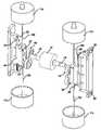
- FIG. 1is a perspective view, partially cut away, of a four piston reciprocating pump assembly incorporating a reciprocating drive apparatus according to an exemplary embodiment of the present invention
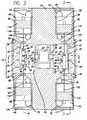
- FIG. 2is a vertical cross-section through the assembly of FIG. 1 ;
- FIG. 3is a cross section on the lines 3 - 3 of FIG. 2 ;
- FIG. 4is a horizontal cross-section through the drive apparatus on the lines 4 - 4 of FIG. 2 ;
- FIG. 4Ais an enlarged view of part of the circled portion of FIG. 4 , illustrating the engagement of the slide member on the linear slide rail in more detail;
- FIG. 5is a perspective view of the assembly of FIGS. 1 to 4 with the housing removed and with the mounting plate for the slide rail on the right hand side cut away to reveal details of the linear bearing rail and slide;
- FIG. 6is a cut away perspective view similar to FIG. 1 illustrating an alternative two piston pump assembly layout
- FIG. 7is a schematic, simplified cross-sectional view of the two piston pump assembly in a first position
- FIG. 8is a cross-sectional view on the lines 8 - 8 of FIG. 7 ;
- FIG. 9is a cross-sectional view similar to FIG. 7 illustrating a different position of the reciprocating drive apparatus and associated pistons.
- FIGS. 1 to 5 of the drawingsillustrate a reciprocating drive apparatus 10 according to an exemplary embodiment of the invention in a four piston pump assembly 20 .
- the reciprocating drive apparatus of this inventionmay alternatively be used to drive the piston of a single piston pump in other applications, or may be used to convert rotational to linear motion, or vice versa, for other possible purposes.
- the apparatus 10drives four pistons 11 A, 11 B, 11 C and 11 D of a four piston pump in a single outer housing 12
- the pump assemblymay be designed to pump any fluid, but is particularly intended for use in pumping gases such as air or oxygen in medical applications.
- Each piston 11 A-Dslides in a respective cylinder 13 A-D in the housing and is linked to the drive apparatus by a piston rod 15 A-D.
- the pistons and cylindersare arranged in aligned, opposing pairs on opposite sides of the drive apparatus, with one pair being aligned along drive axis 16 and the second pair being aligned along drive axis 17 .
- the reciprocating drive apparatus 10is mounted in the central region of housing 12 , between two opposing pairs of pumps.
- the apparatus 10includes a rotational drive or motor 14 in a central chamber 23 with crank shafts or drive shafts 18 , 19 projecting from opposite ends of motor 14 .
- a pair of chambers 21 , 22are located on opposite sides of the central drive chamber 23 , and the crank shafts 18 , 19 project through opposite end caps 24 , 25 and rotary bearings 26 , 28 into the respective chambers 21 , 22 .
- a linear bearingcomprising a linear bearing slide rail 30 , 32 and an associated linear bearing slide member 44 , 45 is mounted in each chamber.
- Each slide rail 30 , 32is rigidly mounted in each chamber 21 , 22 facing the crank shaft by means of a respective rigid mounting plate 34 , 35 which is secured to the outer surface of housing 12 by bolts 36 , 38 .
- the slide railsare rigidly secured to the inner end faces of the respective mounting plates by bolts 39 .
- the mounting plateseach have an outer mounting flange which is bolted to an outer face of the housing, as illustrated in FIG. 4 , and a mounting block which extends inwardly into the respective chamber 21 , 22 to provide a mounting surface for the respective slide rail. This mounting arrangement is extremely strong and secures the linear slide rails or bearing rails rigidly to the housing with no freedom of movement.
- a connecting link or lever 40 , 42is rotatably secured to the offset end of the respective crank shaft 18 , 19 at one end, and is rotatably linked to the respective linear bearing slide member 44 , 45 at its opposite end.
- Each linear bearingmay be of the type used in sliding drawers and the like.
- the engagement between each slide rail 30 , 32 and the respective slide member 44 , 45is illustrated in more detail in FIG. 4A .
- Each slide memberis generally C-shaped to form a channel or groove 46 which engages over the slide rail, with rounded ribs 48 running along the side walls of the channel for engagement in smooth linear raceways or grooves 50 on the opposite sides of the slide rail 30 , 32 .
- the linear bearing railmay alternatively be of the type having ball channels in which balls are moved, with the slide member having corresponding ball channels which cooperate with the ball channels on the rail to sandwich a plurality of balls between the ball channels, with end caps to secure the balls in the channels.
- the linear bearing sets 30 , 44 and 32 , 45each comprise a miniature linear bearing.
- a suitable miniature linear bearingis the C-sleeve Linear Way ML type, Part No. MLC5C2R55HS2 manufactured by IKO Nippon Thompson Co. of Tokyo, Japan.
- a separate connecting plate 52 , 54is bolted to the outer surface of each slide member 44 , 45 , and the respective connecting link is rotatably connected to one end of the respective connecting plate 52 , 54 on its outer face by pivot pin 55 , with a snap ring 56 on the outer end of the pin to keep the bearing in place, as illustrated in FIG. 2 .
- a similar snap ring 58is mounted on the outer end of pivot pin 59 which rotatably connects the outer end of the respective crank shaft 18 , 19 to the respective connecting link.
- the respective pivot pinsare rotatably connected to the connecting links via ball bearings or rotary bearings 57 , as seen in the schematic illustrations of FIGS. 7 to 9 , for smooth operation.
- the first connecting plate 52is rigidly connected at one end to the first piston rod 15 A via a first set screw 60
- the opposite end of the plateis rigidly connected to the end of the second, aligned piston rod 15 B via a second set screw 60
- the second connecting plate 54is connected to the ends of the aligned piston rods 15 C and 15 D by set screws 61 .
- This arrangementensures that the piston rods will follow the movement of the linear slide member 44 , 45 .
- Each slide rail 30 , 32is secured in the housing so as to extend parallel to the axes 16 , 17 of movement of the two aligned pairs of pistons, and the connecting plates 52 and 54 have central longitudinal axes which are aligned with the respective axes 16 , 17 . This ensures that movement of the slide members 44 , 45 along the slide rails will simultaneously move the piston rods in a linear path along the axes 16 , 17 .
- linear bearing slide member and connecting plateare separate elements which are bolted together in the illustrated embodiment, they may alternatively be formed from one solid block.
- the slide memberis elongate in the direction of the reciprocating axis, and has an inner channel portion forming part of a linear bearing which engages over the linear bearing rail and an outer, solid portion which is aligned with the longitudinal axis of travel of the piston or pistons.
- Each piston rod 15extends through a diaphragm seal 62 into the respective cylinder 13 and is fixed to the respective piston.
- the internal diameter of each sealis arranged such that the piston can pass through the seal with its outer surface in sealing engagement with the seal, so that no fluid can leak past the seal.
- the opposite end of each cylinderis sealed by an end cap 64 .
- a glass tube 65 of Pyrex® or the likeis secured in each cylinder and is retained in position against a shoulder in the cylinder by a retaining ring 66 .
- the respective pistonstravel in the glass tube which has a smooth surface to avoid the need for lubricants.
- the pistonsmay be made of graphite to further ensure a smooth sliding motion. As best illustrated in FIG.
- the chambers on each side of the respective pistons 11each have a one way inlet check valve 68 on one side for fluid intake and a one way outlet check valve 70 on the other side for fluid delivery.
- the reciprocating linear motion of the four pistonsgenerates air and delivers air via the one way check valves.
- air in the lower chamberwill be forced out of the chamber via the outlet check valve 70 in that chamber and air will simultaneously be drawn into the upper chamber via its inlet check valve 68 , ready for the next cycle.
- FIG. 2illustrates the relative positions of the four pistons at one point in the cycle.
- the two pistons 11 A and 11 Bare at a central position in their travel in the respective cylinders.
- the piston 11 Cis at the outer end of its travel, with air drawn into the upper chamber and delivered out of the lower chamber.
- the upper piston 11 Dis at the innermost point in its travel, closest to the drive chamber 22 , with air drawn into the outer chamber adjacent end cap 64 and air delivered out of the inner chamber adjacent diaphragm seal 62 .
- FIGS. 1 to 5illustrate a four piston pump.
- FIG. 6illustrates an alternative two piston pump assembly 80 which may be adequate in some applications.
- the upper two pistons and associated cylinders of the first embodimentare eliminated, along with the associated upper portion of housing 12 .
- This embodimentis otherwise identical to that of FIGS. 1 to 5 and like reference numerals are used for like parts as appropriate.
- each connecting plate 52 , 54is connected to only one piston rod, 15 A and 15 C, respectively, at one of its ends. The operation is otherwise identical to that of the first embodiment.
- FIG. 6the reciprocating drive apparatus 60 is mounted in the upper portion of reduced size housing 82 in exactly the same way as it was mounted in a central portion of the housing 12 in the previous embodiment, and is linked to the piston rods 15 to drive the two pistons 11 A and 11 C to reciprocate back and forth in their respective cylinders.
- FIGS. 7 to 9are simplified diagrammatic views of the reciprocating device apparatus 10 attached to two pistons for simplicity.
- each slide member and associated connecting plateis simplified to a single, unitary slide member with a mounting portion for the respective connecting rod.
- FIGS. 7 and 8illustrate the piston 11 C at one end of its stroke, at the upper end of the glass tube 65 in which it slides.
- slide member 45will be at one end position of its axial stroke on slide rail 32 , specifically the upper end as viewed in FIG. 7 .
- the piston 11 A at this pointis at a mid point in its stroke, traveling towards one end of the tube 65 , with the slide member 44 at a mid point in its travel along slide rail 30 .
- piston 11 Chas traveled to the opposite end of its stroke, at the lower end of tube 65 , while piston 11 A has returned to the mid-point of its stroke traveling towards the opposite end of its glass tube 65 .
- each crank shaft 18 , 19causes the associated connecting link 40 , 42 to rotate about pivot connection 55 due to rotation of the offset end of the crank shaft about the axis of rotation of crank shaft 18 , 19 , while the pivot connection 59 rotates relative to the end of the link to which it is connected.
- the connecting linkpulls the associated slide member up and down the linear bearing slide rail on which it is constrained to travel. This provides a relatively simple mechanism for converting rotational motion into true linear motion with little or no side loads.
- the reciprocating drive apparatus of FIGS. 1 to 9is used to convert rotational motion of a rotary drive into linear motion, it could alternatively be reversed with a linear drive connected to the linear bearing and the crank shafts linked to a device to be rotated.
- the pump assembly using the reciprocating drivemay be used to pump any type of fluid, but is particularly intended for pumping gases for use in medical and other applications, for example a ventilator pump for supplying air or oxygen to a patient.
- the reciprocating drive apparatusmay alternatively be used to drive a suction pump, an automobile or airplane pump, or in any other applications where it is necessary to convert rotational into linear motion, or vice versa.
- the reciprocating drive apparatus of this inventionis particularly useful in applications requiring a relatively small pump, such as medical equipment where the pump must be small enough to fit into the limited space available. Such pumps are also required to be low maintenance and cannot use lubricants. This means that there is little tolerance for side loads which often occur in existing reciprocating drives.
- This inventionconverts rotational to linear motion using a miniature linear bearing which is the key to delivering linear motion substantially free of any side loads to the piston.
- the drive apparatushas the capability of driving up to four pistons simultaneously, further reducing size requirements.
Landscapes
- Engineering & Computer Science (AREA)
- Health & Medical Sciences (AREA)
- General Engineering & Computer Science (AREA)
- Mechanical Engineering (AREA)
- Life Sciences & Earth Sciences (AREA)
- Biomedical Technology (AREA)
- Heart & Thoracic Surgery (AREA)
- Hematology (AREA)
- Anesthesiology (AREA)
- Animal Behavior & Ethology (AREA)
- General Health & Medical Sciences (AREA)
- Public Health (AREA)
- Veterinary Medicine (AREA)
- Pulmonology (AREA)
- Emergency Medicine (AREA)
- Transmission Devices (AREA)
- Reciprocating Pumps (AREA)
Abstract
Description
Claims (13)
Priority Applications (2)
| Application Number | Priority Date | Filing Date | Title |
|---|---|---|---|
| US11/315,608US7654802B2 (en) | 2005-12-22 | 2005-12-22 | Reciprocating drive apparatus and method |
| PCT/US2006/062237WO2007076326A2 (en) | 2005-12-22 | 2006-12-18 | Reciprocating drive apparatus and method |
Applications Claiming Priority (1)
| Application Number | Priority Date | Filing Date | Title |
|---|---|---|---|
| US11/315,608US7654802B2 (en) | 2005-12-22 | 2005-12-22 | Reciprocating drive apparatus and method |
Publications (2)
| Publication Number | Publication Date |
|---|---|
| US20070148016A1 US20070148016A1 (en) | 2007-06-28 |
| US7654802B2true US7654802B2 (en) | 2010-02-02 |
Family
ID=38193972
Family Applications (1)
| Application Number | Title | Priority Date | Filing Date |
|---|---|---|---|
| US11/315,608Expired - Fee RelatedUS7654802B2 (en) | 2005-12-22 | 2005-12-22 | Reciprocating drive apparatus and method |
Country Status (2)
| Country | Link |
|---|---|
| US (1) | US7654802B2 (en) |
| WO (1) | WO2007076326A2 (en) |
Cited By (118)
| Publication number | Priority date | Publication date | Assignee | Title |
|---|---|---|---|---|
| US20070284361A1 (en)* | 2004-09-15 | 2007-12-13 | Hossein Nadjafizadeh | System and method for regulating a heating humidifier |
| US20080078390A1 (en)* | 2006-09-29 | 2008-04-03 | Nellcor Puritan Bennett Incorporated | Providing predetermined groups of trending parameters for display in a breathing assistance system |
| US20090205661A1 (en)* | 2008-02-20 | 2009-08-20 | Nellcor Puritan Bennett Llc | Systems and methods for extended volume range ventilation |
| US20090205663A1 (en)* | 2008-02-19 | 2009-08-20 | Nellcor Puritan Bennett Llc | Configuring the operation of an alternating pressure ventilation mode |
| US20090247891A1 (en)* | 2008-03-31 | 2009-10-01 | Nellcor Puritan Bennett Llc | Nitric oxide measurements in patients using flowfeedback |
| US20090247848A1 (en)* | 2008-03-31 | 2009-10-01 | Nellcor Puritan Bennett Llc | Reducing Nuisance Alarms |
| US20090241956A1 (en)* | 2008-03-27 | 2009-10-01 | Nellcor Puritan Bennett Llc | Method for controlling delivery of breathing gas to a patient using multiple ventilation parameters |
| US20090301486A1 (en)* | 2008-06-06 | 2009-12-10 | Nellcor Puritan Bennett Llc | Systems and methods for triggering and cycling a ventilator based on reconstructed patient effort signal |
| US20100051029A1 (en)* | 2008-09-04 | 2010-03-04 | Nellcor Puritan Bennett Llc | Inverse Sawtooth Pressure Wave Train Purging In Medical Ventilators |
| US20100071696A1 (en)* | 2008-09-25 | 2010-03-25 | Nellcor Puritan Bennett Llc | Model-predictive online identification of patient respiratory effort dynamics in medical ventilators |
| US20100071689A1 (en)* | 2008-09-23 | 2010-03-25 | Ron Thiessen | Safe standby mode for ventilator |
| US20100081119A1 (en)* | 2008-09-30 | 2010-04-01 | Nellcor Puritan Bennett Llc | Configurable respiratory muscle pressure generator |
| US20100078017A1 (en)* | 2008-09-30 | 2010-04-01 | Nellcor Puritan Bennett Llc | Wireless communications for a breathing assistance system |
| US20100147303A1 (en)* | 2008-03-31 | 2010-06-17 | Nellcor Puritan Bennett Llc | Determination of patient circuit disconnect in leak-compensated ventilatory support |
| US20100186744A1 (en)* | 2003-07-29 | 2010-07-29 | Claude Andrieux | System and process for supplying respiratory gas under pressure or volumetrically |
| US20100218767A1 (en)* | 2009-02-27 | 2010-09-02 | Nellcor Puritan Bennett Llc | Leak-compensated respiratory mechanics estimation in medical ventilators |
| US20100218766A1 (en)* | 2009-02-27 | 2010-09-02 | Nellcor Puritan Bennett Llc | Customizable mandatory/spontaneous closed loop mode selection |
| US20110011400A1 (en)* | 2009-07-16 | 2011-01-20 | Nellcor Puritan Bennett Llc | Wireless, gas flow-powered sensor system for a breathing assistance system |
| US20110023878A1 (en)* | 2009-07-31 | 2011-02-03 | Nellcor Puritan Bennett Llc | Method And System For Delivering A Single-Breath, Low Flow Recruitment Maneuver |
| US20110041850A1 (en)* | 2009-08-20 | 2011-02-24 | Nellcor Puritan Bennett Llc | Method For Ventilation |
| US20110126834A1 (en)* | 2009-12-01 | 2011-06-02 | Nellcor Puritan Bennett Llc | Exhalation Valve Assembly With Integral Flow Sensor |
| US20110128008A1 (en)* | 2009-12-02 | 2011-06-02 | Nellcor Puritan Bennett Llc | Method And Apparatus For Indicating Battery Cell Status On A Battery Pack Assembly Used During Mechanical Ventilation |
| US20110126837A1 (en)* | 2009-12-01 | 2011-06-02 | Nellcor Puritan Bennett Llc | Exhalation Valve Assembly With Integrated Filter |
| US20110126835A1 (en)* | 2009-12-01 | 2011-06-02 | Nellcor Puritan Bennett Llc | Exhalation Valve Assembly With Integrated Filter And Flow Sensor |
| US20110132361A1 (en)* | 2009-12-04 | 2011-06-09 | Nellcor Puritan Bennett Llc | Ventilation System With Removable Primary Display |
| US20110132365A1 (en)* | 2009-12-03 | 2011-06-09 | Nellcor Puritan Bennett Llc | Ventilator Respiratory Gas Accumulator With Sampling Chamber |
| US20110138323A1 (en)* | 2009-12-04 | 2011-06-09 | Nellcor Puritan Bennett Llc | Visual Indication Of Alarms On A Ventilator Graphical User Interface |
| US20110132368A1 (en)* | 2009-12-04 | 2011-06-09 | Nellcor Puritan Bennett Llc | Display Of Historical Alarm Status |
| US20110138308A1 (en)* | 2009-12-04 | 2011-06-09 | Nellcor Puritan Bennett Llc | Display And Access To Settings On A Ventilator Graphical User Interface |
| US20110138311A1 (en)* | 2009-12-04 | 2011-06-09 | Nellcor Puritan Bennett Llc | Display Of Respiratory Data On A Ventilator Graphical User Interface |
| US20110146683A1 (en)* | 2009-12-21 | 2011-06-23 | Nellcor Puritan Bennett Llc | Sensor Model |
| US20110146681A1 (en)* | 2009-12-21 | 2011-06-23 | Nellcor Puritan Bennett Llc | Adaptive Flow Sensor Model |
| US20110175728A1 (en)* | 2010-01-19 | 2011-07-21 | Nellcor Puritan Bennett Llc | Nuisance Alarm Reduction Method For Therapeutic Parameters |
| US20110213215A1 (en)* | 2010-02-26 | 2011-09-01 | Nellcor Puritan Bennett Llc | Spontaneous Breathing Trial Manager |
| US20110209702A1 (en)* | 2010-02-26 | 2011-09-01 | Nellcor Puritan Bennett Llc | Proportional Solenoid Valve For Low Molecular Weight Gas Mixtures |
| US20120055484A1 (en)* | 2009-05-15 | 2012-03-08 | Geoffrey Mark Shaw | Ventilator |
| US20130061562A1 (en)* | 2011-09-14 | 2013-03-14 | Liqui-Box Corporation | Oscillating pressure system for vertical form fill seal machine |
| US8418691B2 (en) | 2009-03-20 | 2013-04-16 | Covidien Lp | Leak-compensated pressure regulated volume control ventilation |
| US8434480B2 (en) | 2008-03-31 | 2013-05-07 | Covidien Lp | Ventilator leak compensation |
| US8434479B2 (en) | 2009-02-27 | 2013-05-07 | Covidien Lp | Flow rate compensation for transient thermal response of hot-wire anemometers |
| US8443294B2 (en) | 2009-12-18 | 2013-05-14 | Covidien Lp | Visual indication of alarms on a ventilator graphical user interface |
| US8448641B2 (en) | 2009-03-20 | 2013-05-28 | Covidien Lp | Leak-compensated proportional assist ventilation |
| US8450870B1 (en) | 2011-10-07 | 2013-05-28 | Geoffrey Stevens | Use of a sea anchor using river current to generate electricity |
| US8453645B2 (en) | 2006-09-26 | 2013-06-04 | Covidien Lp | Three-dimensional waveform display for a breathing assistance system |
| US8453643B2 (en) | 2010-04-27 | 2013-06-04 | Covidien Lp | Ventilation system with system status display for configuration and program information |
| US8469030B2 (en) | 2009-12-01 | 2013-06-25 | Covidien Lp | Exhalation valve assembly with selectable contagious/non-contagious latch |
| US8511306B2 (en) | 2010-04-27 | 2013-08-20 | Covidien Lp | Ventilation system with system status display for maintenance and service information |
| US8539949B2 (en) | 2010-04-27 | 2013-09-24 | Covidien Lp | Ventilation system with a two-point perspective view |
| US8551006B2 (en) | 2008-09-17 | 2013-10-08 | Covidien Lp | Method for determining hemodynamic effects |
| US8554298B2 (en) | 2010-09-21 | 2013-10-08 | Cividien LP | Medical ventilator with integrated oximeter data |
| US8555882B2 (en) | 1997-03-14 | 2013-10-15 | Covidien Lp | Ventilator breath display and graphic user interface |
| USD692556S1 (en) | 2013-03-08 | 2013-10-29 | Covidien Lp | Expiratory filter body of an exhalation module |
| USD693001S1 (en) | 2013-03-08 | 2013-11-05 | Covidien Lp | Neonate expiratory filter assembly of an exhalation module |
| US8595639B2 (en) | 2010-11-29 | 2013-11-26 | Covidien Lp | Ventilator-initiated prompt regarding detection of fluctuations in resistance |
| US8597198B2 (en) | 2006-04-21 | 2013-12-03 | Covidien Lp | Work of breathing display for a ventilation system |
| US8607791B2 (en) | 2010-06-30 | 2013-12-17 | Covidien Lp | Ventilator-initiated prompt regarding auto-PEEP detection during pressure ventilation |
| US8607790B2 (en) | 2010-06-30 | 2013-12-17 | Covidien Lp | Ventilator-initiated prompt regarding auto-PEEP detection during pressure ventilation of patient exhibiting obstructive component |
| US8607789B2 (en) | 2010-06-30 | 2013-12-17 | Covidien Lp | Ventilator-initiated prompt regarding auto-PEEP detection during volume ventilation of non-triggering patient exhibiting obstructive component |
| US8607788B2 (en) | 2010-06-30 | 2013-12-17 | Covidien Lp | Ventilator-initiated prompt regarding auto-PEEP detection during volume ventilation of triggering patient exhibiting obstructive component |
| US8638200B2 (en) | 2010-05-07 | 2014-01-28 | Covidien Lp | Ventilator-initiated prompt regarding Auto-PEEP detection during volume ventilation of non-triggering patient |
| US8640700B2 (en) | 2008-03-27 | 2014-02-04 | Covidien Lp | Method for selecting target settings in a medical device |
| US8652064B2 (en) | 2008-09-30 | 2014-02-18 | Covidien Lp | Sampling circuit for measuring analytes |
| US8676529B2 (en) | 2011-01-31 | 2014-03-18 | Covidien Lp | Systems and methods for simulation and software testing |
| US8676285B2 (en) | 2010-07-28 | 2014-03-18 | Covidien Lp | Methods for validating patient identity |
| USD701601S1 (en) | 2013-03-08 | 2014-03-25 | Covidien Lp | Condensate vial of an exhalation module |
| US8707952B2 (en) | 2010-02-10 | 2014-04-29 | Covidien Lp | Leak determination in a breathing assistance system |
| US8714154B2 (en) | 2011-03-30 | 2014-05-06 | Covidien Lp | Systems and methods for automatic adjustment of ventilator settings |
| US8720442B2 (en) | 2008-09-26 | 2014-05-13 | Covidien Lp | Systems and methods for managing pressure in a breathing assistance system |
| US8757153B2 (en) | 2010-11-29 | 2014-06-24 | Covidien Lp | Ventilator-initiated prompt regarding detection of double triggering during ventilation |
| US8757152B2 (en) | 2010-11-29 | 2014-06-24 | Covidien Lp | Ventilator-initiated prompt regarding detection of double triggering during a volume-control breath type |
| US8776792B2 (en) | 2011-04-29 | 2014-07-15 | Covidien Lp | Methods and systems for volume-targeted minimum pressure-control ventilation |
| US8783250B2 (en) | 2011-02-27 | 2014-07-22 | Covidien Lp | Methods and systems for transitory ventilation support |
| US8788236B2 (en) | 2011-01-31 | 2014-07-22 | Covidien Lp | Systems and methods for medical device testing |
| US8794234B2 (en) | 2008-09-25 | 2014-08-05 | Covidien Lp | Inversion-based feed-forward compensation of inspiratory trigger dynamics in medical ventilators |
| US8844526B2 (en) | 2012-03-30 | 2014-09-30 | Covidien Lp | Methods and systems for triggering with unknown base flow |
| US8902568B2 (en) | 2006-09-27 | 2014-12-02 | Covidien Lp | Power supply interface system for a breathing assistance system |
| US8950398B2 (en) | 2008-09-30 | 2015-02-10 | Covidien Lp | Supplemental gas safety system for a breathing assistance system |
| US9022031B2 (en) | 2012-01-31 | 2015-05-05 | Covidien Lp | Using estimated carinal pressure for feedback control of carinal pressure during ventilation |
| US9027552B2 (en) | 2012-07-31 | 2015-05-12 | Covidien Lp | Ventilator-initiated prompt or setting regarding detection of asynchrony during ventilation |
| US9038633B2 (en) | 2011-03-02 | 2015-05-26 | Covidien Lp | Ventilator-initiated prompt regarding high delivered tidal volume |
| USD731048S1 (en) | 2013-03-08 | 2015-06-02 | Covidien Lp | EVQ diaphragm of an exhalation module |
| USD731049S1 (en) | 2013-03-05 | 2015-06-02 | Covidien Lp | EVQ housing of an exhalation module |
| USD731065S1 (en) | 2013-03-08 | 2015-06-02 | Covidien Lp | EVQ pressure sensor filter of an exhalation module |
| US9089657B2 (en) | 2011-10-31 | 2015-07-28 | Covidien Lp | Methods and systems for gating user initiated increases in oxygen concentration during ventilation |
| USD736905S1 (en) | 2013-03-08 | 2015-08-18 | Covidien Lp | Exhalation module EVQ housing |
| US9119925B2 (en) | 2009-12-04 | 2015-09-01 | Covidien Lp | Quick initiation of respiratory support via a ventilator user interface |
| US9144658B2 (en) | 2012-04-30 | 2015-09-29 | Covidien Lp | Minimizing imposed expiratory resistance of mechanical ventilator by optimizing exhalation valve control |
| US9186075B2 (en)* | 2009-03-24 | 2015-11-17 | Covidien Lp | Indicating the accuracy of a physiological parameter |
| USD744095S1 (en) | 2013-03-08 | 2015-11-24 | Covidien Lp | Exhalation module EVQ internal flow sensor |
| US9262588B2 (en) | 2009-12-18 | 2016-02-16 | Covidien Lp | Display of respiratory data graphs on a ventilator graphical user interface |
| US9269990B2 (en) | 2008-09-30 | 2016-02-23 | Covidien Lp | Battery management for a breathing assistance system |
| US9289573B2 (en) | 2012-12-28 | 2016-03-22 | Covidien Lp | Ventilator pressure oscillation filter |
| US9302061B2 (en) | 2010-02-26 | 2016-04-05 | Covidien Lp | Event-based delay detection and control of networked systems in medical ventilation |
| US9327089B2 (en) | 2012-03-30 | 2016-05-03 | Covidien Lp | Methods and systems for compensation of tubing related loss effects |
| US9358355B2 (en) | 2013-03-11 | 2016-06-07 | Covidien Lp | Methods and systems for managing a patient move |
| US9364624B2 (en) | 2011-12-07 | 2016-06-14 | Covidien Lp | Methods and systems for adaptive base flow |
| US9375542B2 (en) | 2012-11-08 | 2016-06-28 | Covidien Lp | Systems and methods for monitoring, managing, and/or preventing fatigue during ventilation |
| US9492629B2 (en) | 2013-02-14 | 2016-11-15 | Covidien Lp | Methods and systems for ventilation with unknown exhalation flow and exhalation pressure |
| US9498589B2 (en) | 2011-12-31 | 2016-11-22 | Covidien Lp | Methods and systems for adaptive base flow and leak compensation |
| USD775345S1 (en) | 2015-04-10 | 2016-12-27 | Covidien Lp | Ventilator console |
| US20170022811A1 (en)* | 2014-02-28 | 2017-01-26 | Air Surf Inc. | Fluid rotary machine |
| US9629971B2 (en) | 2011-04-29 | 2017-04-25 | Covidien Lp | Methods and systems for exhalation control and trajectory optimization |
| US9649458B2 (en) | 2008-09-30 | 2017-05-16 | Covidien Lp | Breathing assistance system with multiple pressure sensors |
| US9675771B2 (en) | 2013-10-18 | 2017-06-13 | Covidien Lp | Methods and systems for leak estimation |
| US9808591B2 (en) | 2014-08-15 | 2017-11-07 | Covidien Lp | Methods and systems for breath delivery synchronization |
| US9925346B2 (en) | 2015-01-20 | 2018-03-27 | Covidien Lp | Systems and methods for ventilation with unknown exhalation flow |
| US9950129B2 (en) | 2014-10-27 | 2018-04-24 | Covidien Lp | Ventilation triggering using change-point detection |
| US9950135B2 (en) | 2013-03-15 | 2018-04-24 | Covidien Lp | Maintaining an exhalation valve sensor assembly |
| US9981096B2 (en) | 2013-03-13 | 2018-05-29 | Covidien Lp | Methods and systems for triggering with unknown inspiratory flow |
| US9993604B2 (en) | 2012-04-27 | 2018-06-12 | Covidien Lp | Methods and systems for an optimized proportional assist ventilation |
| US10064583B2 (en) | 2013-08-07 | 2018-09-04 | Covidien Lp | Detection of expiratory airflow limitation in ventilated patient |
| US10207069B2 (en) | 2008-03-31 | 2019-02-19 | Covidien Lp | System and method for determining ventilator leakage during stable periods within a breath |
| US20190128247A1 (en)* | 2017-07-12 | 2019-05-02 | Predominant Pumps & Automation Solutions LLC | System and Method for a Reciprocating Injection Pump |
| US10362967B2 (en) | 2012-07-09 | 2019-07-30 | Covidien Lp | Systems and methods for missed breath detection and indication |
| US10519853B2 (en)* | 2016-12-28 | 2019-12-31 | Z Mechanism Technology Institute Co., Ltd. | Driving apparatus with swinging linear motion mechanism |
| US10668239B2 (en) | 2017-11-14 | 2020-06-02 | Covidien Lp | Systems and methods for drive pressure spontaneous ventilation |
| US10765822B2 (en) | 2016-04-18 | 2020-09-08 | Covidien Lp | Endotracheal tube extubation detection |
| US20240060483A1 (en)* | 2022-10-24 | 2024-02-22 | Foshan Mic Medical Technology Co., Ltd. | Four-cylinder compressor |
Families Citing this family (17)
| Publication number | Priority date | Publication date | Assignee | Title |
|---|---|---|---|---|
| US7476991B2 (en)* | 2007-04-27 | 2009-01-13 | Elek Engine Corporation | Linear electromagnetic driving module and linear electromagnetic driving device |
| US8943950B2 (en)* | 2010-08-24 | 2015-02-03 | Miva Engineering Ltd. | Reciprocating pump flow control |
| US9856866B2 (en) | 2011-01-28 | 2018-01-02 | Wabtec Holding Corp. | Oil-free air compressor for rail vehicles |
| EP2686590B1 (en)* | 2011-02-15 | 2020-04-01 | Origin Medical Devices Inc. | Medical ventilator system with variable orifice rotary valve for controlling gas flow |
| WO2015147971A1 (en)* | 2014-03-27 | 2015-10-01 | Parker-Hannifin Corporation | Piston compressor with glass cylinder and graphite piston |
| ES2687955T3 (en) | 2014-09-11 | 2018-10-30 | Hermetik Hydraulik Ab | Travel device |
| US11247015B2 (en) | 2015-03-24 | 2022-02-15 | Ventec Life Systems, Inc. | Ventilator with integrated oxygen production |
| US10245406B2 (en) | 2015-03-24 | 2019-04-02 | Ventec Life Systems, Inc. | Ventilator with integrated oxygen production |
| JP6700956B2 (en)* | 2016-05-10 | 2020-05-27 | 株式会社スギノマシン | Reciprocating pump |
| US10773049B2 (en) | 2016-06-21 | 2020-09-15 | Ventec Life Systems, Inc. | Cough-assist systems with humidifier bypass |
| CN108194313A (en)* | 2018-02-26 | 2018-06-22 | 浙江北上新能源科技股份有限公司 | A kind of compressor and the mechanized equipment with the compressor |
| WO2019221852A1 (en) | 2018-05-13 | 2019-11-21 | Ahmad Samir Saleh | Portable medical ventilator system using portable oxygen concentrators |
| CN111322220B (en)* | 2020-03-04 | 2021-07-20 | 吉林化工学院 | Rotary rail type reciprocating piston compressor |
| CN112610468B (en)* | 2020-12-14 | 2022-08-26 | 台州市蒙花机械有限公司 | Plunger pump |
| CN112796971B (en)* | 2020-12-28 | 2021-11-02 | 台州市蒙花机械有限公司 | High stability plunger pump |
| CN112682302B (en)* | 2020-12-28 | 2021-09-28 | 台州市蒙花机械有限公司 | Plunger pump |
| CN113113219A (en)* | 2021-03-08 | 2021-07-13 | 安徽绿能技术研究院有限公司 | Copper-iron alloy cooling mechanism |
Citations (33)
| Publication number | Priority date | Publication date | Assignee | Title |
|---|---|---|---|---|
| US122502A (en) | 1872-01-02 | Improvement in mechanical movements | ||
| US124805A (en) | 1872-03-19 | Improvement in apparatus for converting reciprocating into rotary motion | ||
| US129996A (en) | 1872-07-30 | Improvement in crank-expanders | ||
| US285178A (en) | 1883-09-18 | Iviechanical movement | ||
| US297482A (en) | 1884-04-22 | Churn | ||
| US575720A (en) | 1897-01-26 | Gas-engine | ||
| US947233A (en)* | 1909-03-29 | 1910-01-25 | Henry Charles Hammond | Device for converting reciprocating into rotary motion. |
| US1293766A (en) | 1917-12-19 | 1919-02-11 | Frank S Hammond | Internal-combustion engine. |
| FR651805A (en) | 1928-03-27 | 1929-02-28 | Motion transformation process applicable to cylinder and piston machines | |
| GB431237A (en) | 1933-07-27 | 1935-07-03 | Koloman Bors | Improvements in means for converting reciprocatory rectilinear motion into rotary motion |
| US2328918A (en) | 1941-02-25 | 1943-09-07 | Joseph S Mcmanus | Crosshead |
| US3200800A (en) | 1962-04-27 | 1965-08-17 | Bois Francois M Du | Internal combustion engine |
| US3886805A (en) | 1974-04-09 | 1975-06-03 | Ivan Koderman | Crank gear for the conversion of a translational motion into rotation |
| US4419904A (en) | 1979-02-26 | 1983-12-13 | Albury Randolph R | Reciprocating device |
| US4485768A (en)* | 1983-09-09 | 1984-12-04 | Heniges William B | Scotch yoke engine with variable stroke and compression ratio |
| US4524583A (en) | 1983-10-31 | 1985-06-25 | Scheibengraber Karl J | Stirling engine |
| US4559838A (en)* | 1983-10-06 | 1985-12-24 | Neuenschwander Victor L | Scotch yoke piston and crankshaft connection with floating crank pin |
| US4590812A (en)* | 1983-06-16 | 1986-05-27 | Brackett Douglas C | Device for converting between rotary and rectilinear motion |
| US4779472A (en)* | 1986-10-30 | 1988-10-25 | Brackett Douglas C | Motion converter |
| US4915019A (en)* | 1985-08-13 | 1990-04-10 | Jacques Hovaguimian | Mechanism for transforming the reciprocal movement of a piston into a circular movement of a shaft |
| US4995277A (en)* | 1988-05-31 | 1991-02-26 | Ken Yanagisawa | Two dimensional drive system |
| US5092185A (en)* | 1988-07-27 | 1992-03-03 | Balanced Engines, Inc. | Scotch yoke mechanism and power transfer system |
| US5503038A (en)* | 1994-04-01 | 1996-04-02 | Aquino; Giovanni | Free floating multiple eccentric device |
| US5582487A (en) | 1991-09-19 | 1996-12-10 | Thk Co., Ltd. | Linear bearing and its production method |
| US5655406A (en)* | 1993-06-28 | 1997-08-12 | Yugen Kaisha Sozoan | Rotary motion drive system |
| US5762480A (en) | 1996-04-16 | 1998-06-09 | Adahan; Carmeli | Reciprocating machine |
| US5836751A (en) | 1995-06-21 | 1998-11-17 | Divwatt (Proprietary) Limited | Reciprocating piston pump |
| US5943987A (en)* | 1995-02-14 | 1999-08-31 | Bayerische Motoren Werke Aktiengesellschaft | Reciprocating piston engine with adjacent cylinders in the crankshaft direction in an engine case |
| WO2000037827A1 (en) | 1998-12-21 | 2000-06-29 | Anton Braun | Improved linear drives |
| US6539835B1 (en)* | 1998-06-04 | 2003-04-01 | Gunnar Vestergaard Rasmussen | I-yoke mechanism |
| US6631671B1 (en)* | 1999-03-09 | 2003-10-14 | Aleksey Feliksovich Vool | Piston-type machine with conrod-free mechanism |
| US20050139021A1 (en) | 2003-12-29 | 2005-06-30 | Positec Powre Tools (Suzhou) Co., Ltd. | Reciprocating mechanism |
| US7004522B2 (en)* | 2002-02-04 | 2006-02-28 | Smc Kabushiki Kaisha | Suction unit |
- 2005
- 2005-12-22USUS11/315,608patent/US7654802B2/ennot_activeExpired - Fee Related
- 2006
- 2006-12-18WOPCT/US2006/062237patent/WO2007076326A2/enactiveApplication Filing
Patent Citations (33)
| Publication number | Priority date | Publication date | Assignee | Title |
|---|---|---|---|---|
| US122502A (en) | 1872-01-02 | Improvement in mechanical movements | ||
| US124805A (en) | 1872-03-19 | Improvement in apparatus for converting reciprocating into rotary motion | ||
| US129996A (en) | 1872-07-30 | Improvement in crank-expanders | ||
| US285178A (en) | 1883-09-18 | Iviechanical movement | ||
| US297482A (en) | 1884-04-22 | Churn | ||
| US575720A (en) | 1897-01-26 | Gas-engine | ||
| US947233A (en)* | 1909-03-29 | 1910-01-25 | Henry Charles Hammond | Device for converting reciprocating into rotary motion. |
| US1293766A (en) | 1917-12-19 | 1919-02-11 | Frank S Hammond | Internal-combustion engine. |
| FR651805A (en) | 1928-03-27 | 1929-02-28 | Motion transformation process applicable to cylinder and piston machines | |
| GB431237A (en) | 1933-07-27 | 1935-07-03 | Koloman Bors | Improvements in means for converting reciprocatory rectilinear motion into rotary motion |
| US2328918A (en) | 1941-02-25 | 1943-09-07 | Joseph S Mcmanus | Crosshead |
| US3200800A (en) | 1962-04-27 | 1965-08-17 | Bois Francois M Du | Internal combustion engine |
| US3886805A (en) | 1974-04-09 | 1975-06-03 | Ivan Koderman | Crank gear for the conversion of a translational motion into rotation |
| US4419904A (en) | 1979-02-26 | 1983-12-13 | Albury Randolph R | Reciprocating device |
| US4590812A (en)* | 1983-06-16 | 1986-05-27 | Brackett Douglas C | Device for converting between rotary and rectilinear motion |
| US4485768A (en)* | 1983-09-09 | 1984-12-04 | Heniges William B | Scotch yoke engine with variable stroke and compression ratio |
| US4559838A (en)* | 1983-10-06 | 1985-12-24 | Neuenschwander Victor L | Scotch yoke piston and crankshaft connection with floating crank pin |
| US4524583A (en) | 1983-10-31 | 1985-06-25 | Scheibengraber Karl J | Stirling engine |
| US4915019A (en)* | 1985-08-13 | 1990-04-10 | Jacques Hovaguimian | Mechanism for transforming the reciprocal movement of a piston into a circular movement of a shaft |
| US4779472A (en)* | 1986-10-30 | 1988-10-25 | Brackett Douglas C | Motion converter |
| US4995277A (en)* | 1988-05-31 | 1991-02-26 | Ken Yanagisawa | Two dimensional drive system |
| US5092185A (en)* | 1988-07-27 | 1992-03-03 | Balanced Engines, Inc. | Scotch yoke mechanism and power transfer system |
| US5582487A (en) | 1991-09-19 | 1996-12-10 | Thk Co., Ltd. | Linear bearing and its production method |
| US5655406A (en)* | 1993-06-28 | 1997-08-12 | Yugen Kaisha Sozoan | Rotary motion drive system |
| US5503038A (en)* | 1994-04-01 | 1996-04-02 | Aquino; Giovanni | Free floating multiple eccentric device |
| US5943987A (en)* | 1995-02-14 | 1999-08-31 | Bayerische Motoren Werke Aktiengesellschaft | Reciprocating piston engine with adjacent cylinders in the crankshaft direction in an engine case |
| US5836751A (en) | 1995-06-21 | 1998-11-17 | Divwatt (Proprietary) Limited | Reciprocating piston pump |
| US5762480A (en) | 1996-04-16 | 1998-06-09 | Adahan; Carmeli | Reciprocating machine |
| US6539835B1 (en)* | 1998-06-04 | 2003-04-01 | Gunnar Vestergaard Rasmussen | I-yoke mechanism |
| WO2000037827A1 (en) | 1998-12-21 | 2000-06-29 | Anton Braun | Improved linear drives |
| US6631671B1 (en)* | 1999-03-09 | 2003-10-14 | Aleksey Feliksovich Vool | Piston-type machine with conrod-free mechanism |
| US7004522B2 (en)* | 2002-02-04 | 2006-02-28 | Smc Kabushiki Kaisha | Suction unit |
| US20050139021A1 (en) | 2003-12-29 | 2005-06-30 | Positec Powre Tools (Suzhou) Co., Ltd. | Reciprocating mechanism |
Non-Patent Citations (2)
| Title |
|---|
| International Preliminary Report on Patentability with Written Opinion of the International Searching Authority from related PCT/US2006/062237, dated Jun. 24, 2008. |
| International Search Report for PCT/US06/62237. |
Cited By (208)
| Publication number | Priority date | Publication date | Assignee | Title |
|---|---|---|---|---|
| US8555881B2 (en) | 1997-03-14 | 2013-10-15 | Covidien Lp | Ventilator breath display and graphic interface |
| US8555882B2 (en) | 1997-03-14 | 2013-10-15 | Covidien Lp | Ventilator breath display and graphic user interface |
| US8800557B2 (en) | 2003-07-29 | 2014-08-12 | Covidien Lp | System and process for supplying respiratory gas under pressure or volumetrically |
| US20100186744A1 (en)* | 2003-07-29 | 2010-07-29 | Claude Andrieux | System and process for supplying respiratory gas under pressure or volumetrically |
| US9084865B2 (en) | 2004-09-15 | 2015-07-21 | Covidien Ag | System and method for regulating a heating humidifier |
| US20070284361A1 (en)* | 2004-09-15 | 2007-12-13 | Hossein Nadjafizadeh | System and method for regulating a heating humidifier |
| US10582880B2 (en) | 2006-04-21 | 2020-03-10 | Covidien Lp | Work of breathing display for a ventilation system |
| US8597198B2 (en) | 2006-04-21 | 2013-12-03 | Covidien Lp | Work of breathing display for a ventilation system |
| US8453645B2 (en) | 2006-09-26 | 2013-06-04 | Covidien Lp | Three-dimensional waveform display for a breathing assistance system |
| US8902568B2 (en) | 2006-09-27 | 2014-12-02 | Covidien Lp | Power supply interface system for a breathing assistance system |
| US20080078390A1 (en)* | 2006-09-29 | 2008-04-03 | Nellcor Puritan Bennett Incorporated | Providing predetermined groups of trending parameters for display in a breathing assistance system |
| US20090205663A1 (en)* | 2008-02-19 | 2009-08-20 | Nellcor Puritan Bennett Llc | Configuring the operation of an alternating pressure ventilation mode |
| US20090205661A1 (en)* | 2008-02-20 | 2009-08-20 | Nellcor Puritan Bennett Llc | Systems and methods for extended volume range ventilation |
| US20090241956A1 (en)* | 2008-03-27 | 2009-10-01 | Nellcor Puritan Bennett Llc | Method for controlling delivery of breathing gas to a patient using multiple ventilation parameters |
| US8640700B2 (en) | 2008-03-27 | 2014-02-04 | Covidien Lp | Method for selecting target settings in a medical device |
| US8434480B2 (en) | 2008-03-31 | 2013-05-07 | Covidien Lp | Ventilator leak compensation |
| US10207069B2 (en) | 2008-03-31 | 2019-02-19 | Covidien Lp | System and method for determining ventilator leakage during stable periods within a breath |
| US20100147303A1 (en)* | 2008-03-31 | 2010-06-17 | Nellcor Puritan Bennett Llc | Determination of patient circuit disconnect in leak-compensated ventilatory support |
| US8792949B2 (en) | 2008-03-31 | 2014-07-29 | Covidien Lp | Reducing nuisance alarms |
| US8425428B2 (en) | 2008-03-31 | 2013-04-23 | Covidien Lp | Nitric oxide measurements in patients using flowfeedback |
| US8746248B2 (en) | 2008-03-31 | 2014-06-10 | Covidien Lp | Determination of patient circuit disconnect in leak-compensated ventilatory support |
| US11027080B2 (en) | 2008-03-31 | 2021-06-08 | Covidien Lp | System and method for determining ventilator leakage during stable periods within a breath |
| US9820681B2 (en) | 2008-03-31 | 2017-11-21 | Covidien Lp | Reducing nuisance alarms |
| US9421338B2 (en) | 2008-03-31 | 2016-08-23 | Covidien Lp | Ventilator leak compensation |
| US20090247848A1 (en)* | 2008-03-31 | 2009-10-01 | Nellcor Puritan Bennett Llc | Reducing Nuisance Alarms |
| US20090247891A1 (en)* | 2008-03-31 | 2009-10-01 | Nellcor Puritan Bennett Llc | Nitric oxide measurements in patients using flowfeedback |
| US10828437B2 (en) | 2008-06-06 | 2020-11-10 | Covidien Lp | Systems and methods for triggering and cycling a ventilator based on reconstructed patient effort signal |
| US20090301490A1 (en)* | 2008-06-06 | 2009-12-10 | Nellcor Puritan Bennett Llc | Systems and methods for determining patient effort and/or respiratory parameters in a ventilation system |
| US8826907B2 (en) | 2008-06-06 | 2014-09-09 | Covidien Lp | Systems and methods for determining patient effort and/or respiratory parameters in a ventilation system |
| US8485185B2 (en) | 2008-06-06 | 2013-07-16 | Covidien Lp | Systems and methods for ventilation in proportion to patient effort |
| US20090301486A1 (en)* | 2008-06-06 | 2009-12-10 | Nellcor Puritan Bennett Llc | Systems and methods for triggering and cycling a ventilator based on reconstructed patient effort signal |
| US9126001B2 (en) | 2008-06-06 | 2015-09-08 | Covidien Lp | Systems and methods for ventilation in proportion to patient effort |
| US9114220B2 (en) | 2008-06-06 | 2015-08-25 | Covidien Lp | Systems and methods for triggering and cycling a ventilator based on reconstructed patient effort signal |
| US9956363B2 (en) | 2008-06-06 | 2018-05-01 | Covidien Lp | Systems and methods for triggering and cycling a ventilator based on reconstructed patient effort signal |
| US9925345B2 (en) | 2008-06-06 | 2018-03-27 | Covidien Lp | Systems and methods for determining patient effort and/or respiratory parameters in a ventilation system |
| US20090301491A1 (en)* | 2008-06-06 | 2009-12-10 | Nellcor Puritan Bennett Llc | Systems and methods for ventilation in proportion to patient effort |
| US8485184B2 (en) | 2008-06-06 | 2013-07-16 | Covidien Lp | Systems and methods for monitoring and displaying respiratory information |
| US8485183B2 (en) | 2008-06-06 | 2013-07-16 | Covidien Lp | Systems and methods for triggering and cycling a ventilator based on reconstructed patient effort signal |
| US20100051029A1 (en)* | 2008-09-04 | 2010-03-04 | Nellcor Puritan Bennett Llc | Inverse Sawtooth Pressure Wave Train Purging In Medical Ventilators |
| US20100051026A1 (en)* | 2008-09-04 | 2010-03-04 | Nellcor Puritan Bennett Llc | Ventilator With Controlled Purge Function |
| US8528554B2 (en) | 2008-09-04 | 2013-09-10 | Covidien Lp | Inverse sawtooth pressure wave train purging in medical ventilators |
| US8551006B2 (en) | 2008-09-17 | 2013-10-08 | Covidien Lp | Method for determining hemodynamic effects |
| US9414769B2 (en) | 2008-09-17 | 2016-08-16 | Covidien Lp | Method for determining hemodynamic effects |
| US8424520B2 (en) | 2008-09-23 | 2013-04-23 | Covidien Lp | Safe standby mode for ventilator |
| US20100071689A1 (en)* | 2008-09-23 | 2010-03-25 | Ron Thiessen | Safe standby mode for ventilator |
| US11344689B2 (en) | 2008-09-23 | 2022-05-31 | Covidien Lp | Safe standby mode for ventilator |
| US10493225B2 (en) | 2008-09-23 | 2019-12-03 | Covidien Lp | Safe standby mode for ventilator |
| US9381314B2 (en) | 2008-09-23 | 2016-07-05 | Covidien Lp | Safe standby mode for ventilator |
| US20100071696A1 (en)* | 2008-09-25 | 2010-03-25 | Nellcor Puritan Bennett Llc | Model-predictive online identification of patient respiratory effort dynamics in medical ventilators |
| US8794234B2 (en) | 2008-09-25 | 2014-08-05 | Covidien Lp | Inversion-based feed-forward compensation of inspiratory trigger dynamics in medical ventilators |
| US8720442B2 (en) | 2008-09-26 | 2014-05-13 | Covidien Lp | Systems and methods for managing pressure in a breathing assistance system |
| US8652064B2 (en) | 2008-09-30 | 2014-02-18 | Covidien Lp | Sampling circuit for measuring analytes |
| US8585412B2 (en) | 2008-09-30 | 2013-11-19 | Covidien Lp | Configurable respiratory muscle pressure generator |
| US20100078017A1 (en)* | 2008-09-30 | 2010-04-01 | Nellcor Puritan Bennett Llc | Wireless communications for a breathing assistance system |
| US20100081119A1 (en)* | 2008-09-30 | 2010-04-01 | Nellcor Puritan Bennett Llc | Configurable respiratory muscle pressure generator |
| US8950398B2 (en) | 2008-09-30 | 2015-02-10 | Covidien Lp | Supplemental gas safety system for a breathing assistance system |
| US9649458B2 (en) | 2008-09-30 | 2017-05-16 | Covidien Lp | Breathing assistance system with multiple pressure sensors |
| US9269990B2 (en) | 2008-09-30 | 2016-02-23 | Covidien Lp | Battery management for a breathing assistance system |
| US8439032B2 (en) | 2008-09-30 | 2013-05-14 | Covidien Lp | Wireless communications for a breathing assistance system |
| US8424521B2 (en) | 2009-02-27 | 2013-04-23 | Covidien Lp | Leak-compensated respiratory mechanics estimation in medical ventilators |
| US20100218766A1 (en)* | 2009-02-27 | 2010-09-02 | Nellcor Puritan Bennett Llc | Customizable mandatory/spontaneous closed loop mode selection |
| US20100218767A1 (en)* | 2009-02-27 | 2010-09-02 | Nellcor Puritan Bennett Llc | Leak-compensated respiratory mechanics estimation in medical ventilators |
| US8434479B2 (en) | 2009-02-27 | 2013-05-07 | Covidien Lp | Flow rate compensation for transient thermal response of hot-wire anemometers |
| US8905024B2 (en) | 2009-02-27 | 2014-12-09 | Covidien Lp | Flow rate compensation for transient thermal response of hot-wire anemometers |
| US8973577B2 (en) | 2009-03-20 | 2015-03-10 | Covidien Lp | Leak-compensated pressure regulated volume control ventilation |
| US8418691B2 (en) | 2009-03-20 | 2013-04-16 | Covidien Lp | Leak-compensated pressure regulated volume control ventilation |
| US8448641B2 (en) | 2009-03-20 | 2013-05-28 | Covidien Lp | Leak-compensated proportional assist ventilation |
| US8978650B2 (en) | 2009-03-20 | 2015-03-17 | Covidien Lp | Leak-compensated proportional assist ventilation |
| US9186075B2 (en)* | 2009-03-24 | 2015-11-17 | Covidien Lp | Indicating the accuracy of a physiological parameter |
| US20120055484A1 (en)* | 2009-05-15 | 2012-03-08 | Geoffrey Mark Shaw | Ventilator |
| US20110011400A1 (en)* | 2009-07-16 | 2011-01-20 | Nellcor Puritan Bennett Llc | Wireless, gas flow-powered sensor system for a breathing assistance system |
| US8776790B2 (en) | 2009-07-16 | 2014-07-15 | Covidien Lp | Wireless, gas flow-powered sensor system for a breathing assistance system |
| US20110023878A1 (en)* | 2009-07-31 | 2011-02-03 | Nellcor Puritan Bennett Llc | Method And System For Delivering A Single-Breath, Low Flow Recruitment Maneuver |
| US20110041850A1 (en)* | 2009-08-20 | 2011-02-24 | Nellcor Puritan Bennett Llc | Method For Ventilation |
| US8789529B2 (en) | 2009-08-20 | 2014-07-29 | Covidien Lp | Method for ventilation |
| US9205221B2 (en) | 2009-12-01 | 2015-12-08 | Covidien Lp | Exhalation valve assembly with integral flow sensor |
| US8469030B2 (en) | 2009-12-01 | 2013-06-25 | Covidien Lp | Exhalation valve assembly with selectable contagious/non-contagious latch |
| US8439036B2 (en) | 2009-12-01 | 2013-05-14 | Covidien Lp | Exhalation valve assembly with integral flow sensor |
| US8439037B2 (en) | 2009-12-01 | 2013-05-14 | Covidien Lp | Exhalation valve assembly with integrated filter and flow sensor |
| US9987457B2 (en) | 2009-12-01 | 2018-06-05 | Covidien Lp | Exhalation valve assembly with integral flow sensor |
| US8469031B2 (en) | 2009-12-01 | 2013-06-25 | Covidien Lp | Exhalation valve assembly with integrated filter |
| US20110126835A1 (en)* | 2009-12-01 | 2011-06-02 | Nellcor Puritan Bennett Llc | Exhalation Valve Assembly With Integrated Filter And Flow Sensor |
| US20110126837A1 (en)* | 2009-12-01 | 2011-06-02 | Nellcor Puritan Bennett Llc | Exhalation Valve Assembly With Integrated Filter |
| US20110126834A1 (en)* | 2009-12-01 | 2011-06-02 | Nellcor Puritan Bennett Llc | Exhalation Valve Assembly With Integral Flow Sensor |
| US8547062B2 (en) | 2009-12-02 | 2013-10-01 | Covidien Lp | Apparatus and system for a battery pack assembly used during mechanical ventilation |
| US8421465B2 (en) | 2009-12-02 | 2013-04-16 | Covidien Lp | Method and apparatus for indicating battery cell status on a battery pack assembly used during mechanical ventilation |
| US9364626B2 (en) | 2009-12-02 | 2016-06-14 | Covidien Lp | Battery pack assembly having a status indicator for use during mechanical ventilation |
| US20110128008A1 (en)* | 2009-12-02 | 2011-06-02 | Nellcor Puritan Bennett Llc | Method And Apparatus For Indicating Battery Cell Status On A Battery Pack Assembly Used During Mechanical Ventilation |
| US20110132364A1 (en)* | 2009-12-03 | 2011-06-09 | Nellcor Puritan Bennett Llc | Ventilator Respiratory Gas Accumulator With Dip Tube |
| US8434481B2 (en) | 2009-12-03 | 2013-05-07 | Covidien Lp | Ventilator respiratory gas accumulator with dip tube |
| US20110132365A1 (en)* | 2009-12-03 | 2011-06-09 | Nellcor Puritan Bennett Llc | Ventilator Respiratory Gas Accumulator With Sampling Chamber |
| US9089665B2 (en) | 2009-12-03 | 2015-07-28 | Covidien Lp | Ventilator respiratory variable-sized gas accumulator |
| US20110132367A1 (en)* | 2009-12-03 | 2011-06-09 | Nellcor Puritan Bennett Llc | Ventilator Respiratory Variable-Sized Gas Accumulator |
| US8424523B2 (en) | 2009-12-03 | 2013-04-23 | Covidien Lp | Ventilator respiratory gas accumulator with purge valve |
| US8434484B2 (en) | 2009-12-03 | 2013-05-07 | Covidien Lp | Ventilator Respiratory Variable-Sized Gas Accumulator |
| US8434483B2 (en) | 2009-12-03 | 2013-05-07 | Covidien Lp | Ventilator respiratory gas accumulator with sampling chamber |
| US8924878B2 (en) | 2009-12-04 | 2014-12-30 | Covidien Lp | Display and access to settings on a ventilator graphical user interface |
| US8418692B2 (en) | 2009-12-04 | 2013-04-16 | Covidien Lp | Ventilation system with removable primary display |
| US20110132361A1 (en)* | 2009-12-04 | 2011-06-09 | Nellcor Puritan Bennett Llc | Ventilation System With Removable Primary Display |
| US20110133936A1 (en)* | 2009-12-04 | 2011-06-09 | Nellcor Puritan Bennett Llc | Interactive Multilevel Alarm |
| US20110132362A1 (en)* | 2009-12-04 | 2011-06-09 | Nellcor Puritan Bennett Llc | Ventilation System With System Status Display Including A User Interface |
| US20110138323A1 (en)* | 2009-12-04 | 2011-06-09 | Nellcor Puritan Bennett Llc | Visual Indication Of Alarms On A Ventilator Graphical User Interface |
| US20110132368A1 (en)* | 2009-12-04 | 2011-06-09 | Nellcor Puritan Bennett Llc | Display Of Historical Alarm Status |
| US8677996B2 (en) | 2009-12-04 | 2014-03-25 | Covidien Lp | Ventilation system with system status display including a user interface |
| US9814851B2 (en) | 2009-12-04 | 2017-11-14 | Covidien Lp | Alarm indication system |
| US20110132371A1 (en)* | 2009-12-04 | 2011-06-09 | Nellcor Puritan Bennett, LLC. | Alarm Indication System |
| US20110138308A1 (en)* | 2009-12-04 | 2011-06-09 | Nellcor Puritan Bennett Llc | Display And Access To Settings On A Ventilator Graphical User Interface |
| US8482415B2 (en) | 2009-12-04 | 2013-07-09 | Covidien Lp | Interactive multilevel alarm |
| US9119925B2 (en) | 2009-12-04 | 2015-09-01 | Covidien Lp | Quick initiation of respiratory support via a ventilator user interface |
| US20110138311A1 (en)* | 2009-12-04 | 2011-06-09 | Nellcor Puritan Bennett Llc | Display Of Respiratory Data On A Ventilator Graphical User Interface |
| US8443294B2 (en) | 2009-12-18 | 2013-05-14 | Covidien Lp | Visual indication of alarms on a ventilator graphical user interface |
| US8499252B2 (en) | 2009-12-18 | 2013-07-30 | Covidien Lp | Display of respiratory data graphs on a ventilator graphical user interface |
| US9262588B2 (en) | 2009-12-18 | 2016-02-16 | Covidien Lp | Display of respiratory data graphs on a ventilator graphical user interface |
| US20110146681A1 (en)* | 2009-12-21 | 2011-06-23 | Nellcor Puritan Bennett Llc | Adaptive Flow Sensor Model |
| US20110146683A1 (en)* | 2009-12-21 | 2011-06-23 | Nellcor Puritan Bennett Llc | Sensor Model |
| US9411494B2 (en) | 2010-01-19 | 2016-08-09 | Covidien Lp | Nuisance alarm reduction method for therapeutic parameters |
| US8400290B2 (en) | 2010-01-19 | 2013-03-19 | Covidien Lp | Nuisance alarm reduction method for therapeutic parameters |
| US20110175728A1 (en)* | 2010-01-19 | 2011-07-21 | Nellcor Puritan Bennett Llc | Nuisance Alarm Reduction Method For Therapeutic Parameters |
| US8939150B2 (en) | 2010-02-10 | 2015-01-27 | Covidien Lp | Leak determination in a breathing assistance system |
| US11033700B2 (en) | 2010-02-10 | 2021-06-15 | Covidien Lp | Leak determination in a breathing assistance system |
| US8707952B2 (en) | 2010-02-10 | 2014-04-29 | Covidien Lp | Leak determination in a breathing assistance system |
| US10463819B2 (en) | 2010-02-10 | 2019-11-05 | Covidien Lp | Leak determination in a breathing assistance system |
| US9254369B2 (en) | 2010-02-10 | 2016-02-09 | Covidien Lp | Leak determination in a breathing assistance system |
| US20110209702A1 (en)* | 2010-02-26 | 2011-09-01 | Nellcor Puritan Bennett Llc | Proportional Solenoid Valve For Low Molecular Weight Gas Mixtures |
| US9302061B2 (en) | 2010-02-26 | 2016-04-05 | Covidien Lp | Event-based delay detection and control of networked systems in medical ventilation |
| US20110213215A1 (en)* | 2010-02-26 | 2011-09-01 | Nellcor Puritan Bennett Llc | Spontaneous Breathing Trial Manager |
| US9387297B2 (en) | 2010-04-27 | 2016-07-12 | Covidien Lp | Ventilation system with a two-point perspective view |
| US8539949B2 (en) | 2010-04-27 | 2013-09-24 | Covidien Lp | Ventilation system with a two-point perspective view |
| US8453643B2 (en) | 2010-04-27 | 2013-06-04 | Covidien Lp | Ventilation system with system status display for configuration and program information |
| US8511306B2 (en) | 2010-04-27 | 2013-08-20 | Covidien Lp | Ventilation system with system status display for maintenance and service information |
| US8638200B2 (en) | 2010-05-07 | 2014-01-28 | Covidien Lp | Ventilator-initiated prompt regarding Auto-PEEP detection during volume ventilation of non-triggering patient |
| US9030304B2 (en) | 2010-05-07 | 2015-05-12 | Covidien Lp | Ventilator-initiated prompt regarding auto-peep detection during ventilation of non-triggering patient |
| US8607790B2 (en) | 2010-06-30 | 2013-12-17 | Covidien Lp | Ventilator-initiated prompt regarding auto-PEEP detection during pressure ventilation of patient exhibiting obstructive component |
| US8607789B2 (en) | 2010-06-30 | 2013-12-17 | Covidien Lp | Ventilator-initiated prompt regarding auto-PEEP detection during volume ventilation of non-triggering patient exhibiting obstructive component |
| US8607791B2 (en) | 2010-06-30 | 2013-12-17 | Covidien Lp | Ventilator-initiated prompt regarding auto-PEEP detection during pressure ventilation |
| US8607788B2 (en) | 2010-06-30 | 2013-12-17 | Covidien Lp | Ventilator-initiated prompt regarding auto-PEEP detection during volume ventilation of triggering patient exhibiting obstructive component |
| US8676285B2 (en) | 2010-07-28 | 2014-03-18 | Covidien Lp | Methods for validating patient identity |
| US8554298B2 (en) | 2010-09-21 | 2013-10-08 | Cividien LP | Medical ventilator with integrated oximeter data |
| US8757153B2 (en) | 2010-11-29 | 2014-06-24 | Covidien Lp | Ventilator-initiated prompt regarding detection of double triggering during ventilation |
| US8757152B2 (en) | 2010-11-29 | 2014-06-24 | Covidien Lp | Ventilator-initiated prompt regarding detection of double triggering during a volume-control breath type |
| US8595639B2 (en) | 2010-11-29 | 2013-11-26 | Covidien Lp | Ventilator-initiated prompt regarding detection of fluctuations in resistance |
| US8676529B2 (en) | 2011-01-31 | 2014-03-18 | Covidien Lp | Systems and methods for simulation and software testing |
| US8788236B2 (en) | 2011-01-31 | 2014-07-22 | Covidien Lp | Systems and methods for medical device testing |
| US8783250B2 (en) | 2011-02-27 | 2014-07-22 | Covidien Lp | Methods and systems for transitory ventilation support |
| US9038633B2 (en) | 2011-03-02 | 2015-05-26 | Covidien Lp | Ventilator-initiated prompt regarding high delivered tidal volume |
| US8714154B2 (en) | 2011-03-30 | 2014-05-06 | Covidien Lp | Systems and methods for automatic adjustment of ventilator settings |
| US8776792B2 (en) | 2011-04-29 | 2014-07-15 | Covidien Lp | Methods and systems for volume-targeted minimum pressure-control ventilation |
| US10850056B2 (en) | 2011-04-29 | 2020-12-01 | Covidien Lp | Methods and systems for exhalation control and trajectory optimization |
| US11638796B2 (en) | 2011-04-29 | 2023-05-02 | Covidien Lp | Methods and systems for exhalation control and trajectory optimization |
| US9629971B2 (en) | 2011-04-29 | 2017-04-25 | Covidien Lp | Methods and systems for exhalation control and trajectory optimization |
| US9440757B2 (en)* | 2011-09-14 | 2016-09-13 | Liqui-Box Corporation | Process for forming and filling a pouch on a VFFS machine |
| US9327856B2 (en)* | 2011-09-14 | 2016-05-03 | Liqui-Box Corporation | Oscillating pressure system for vertical form fill seal machine |
| US20130061562A1 (en)* | 2011-09-14 | 2013-03-14 | Liqui-Box Corporation | Oscillating pressure system for vertical form fill seal machine |
| US8450870B1 (en) | 2011-10-07 | 2013-05-28 | Geoffrey Stevens | Use of a sea anchor using river current to generate electricity |
| US9089657B2 (en) | 2011-10-31 | 2015-07-28 | Covidien Lp | Methods and systems for gating user initiated increases in oxygen concentration during ventilation |
| US9364624B2 (en) | 2011-12-07 | 2016-06-14 | Covidien Lp | Methods and systems for adaptive base flow |
| US9498589B2 (en) | 2011-12-31 | 2016-11-22 | Covidien Lp | Methods and systems for adaptive base flow and leak compensation |
| US11833297B2 (en) | 2011-12-31 | 2023-12-05 | Covidien Lp | Methods and systems for adaptive base flow and leak compensation |
| US10709854B2 (en) | 2011-12-31 | 2020-07-14 | Covidien Lp | Methods and systems for adaptive base flow and leak compensation |
| US9022031B2 (en) | 2012-01-31 | 2015-05-05 | Covidien Lp | Using estimated carinal pressure for feedback control of carinal pressure during ventilation |
| US9327089B2 (en) | 2012-03-30 | 2016-05-03 | Covidien Lp | Methods and systems for compensation of tubing related loss effects |
| US8844526B2 (en) | 2012-03-30 | 2014-09-30 | Covidien Lp | Methods and systems for triggering with unknown base flow |
| US10029057B2 (en) | 2012-03-30 | 2018-07-24 | Covidien Lp | Methods and systems for triggering with unknown base flow |
| US10806879B2 (en) | 2012-04-27 | 2020-10-20 | Covidien Lp | Methods and systems for an optimized proportional assist ventilation |
| US9993604B2 (en) | 2012-04-27 | 2018-06-12 | Covidien Lp | Methods and systems for an optimized proportional assist ventilation |
| US9144658B2 (en) | 2012-04-30 | 2015-09-29 | Covidien Lp | Minimizing imposed expiratory resistance of mechanical ventilator by optimizing exhalation valve control |
| US10362967B2 (en) | 2012-07-09 | 2019-07-30 | Covidien Lp | Systems and methods for missed breath detection and indication |
| US11642042B2 (en) | 2012-07-09 | 2023-05-09 | Covidien Lp | Systems and methods for missed breath detection and indication |
| US9027552B2 (en) | 2012-07-31 | 2015-05-12 | Covidien Lp | Ventilator-initiated prompt or setting regarding detection of asynchrony during ventilation |
| US9375542B2 (en) | 2012-11-08 | 2016-06-28 | Covidien Lp | Systems and methods for monitoring, managing, and/or preventing fatigue during ventilation |
| US10543326B2 (en) | 2012-11-08 | 2020-01-28 | Covidien Lp | Systems and methods for monitoring, managing, and preventing fatigue during ventilation |
| US11229759B2 (en) | 2012-11-08 | 2022-01-25 | Covidien Lp | Systems and methods for monitoring, managing, and preventing fatigue during ventilation |
| US9289573B2 (en) | 2012-12-28 | 2016-03-22 | Covidien Lp | Ventilator pressure oscillation filter |
| US9492629B2 (en) | 2013-02-14 | 2016-11-15 | Covidien Lp | Methods and systems for ventilation with unknown exhalation flow and exhalation pressure |
| USD731049S1 (en) | 2013-03-05 | 2015-06-02 | Covidien Lp | EVQ housing of an exhalation module |
| USD693001S1 (en) | 2013-03-08 | 2013-11-05 | Covidien Lp | Neonate expiratory filter assembly of an exhalation module |
| USD692556S1 (en) | 2013-03-08 | 2013-10-29 | Covidien Lp | Expiratory filter body of an exhalation module |
| USD736905S1 (en) | 2013-03-08 | 2015-08-18 | Covidien Lp | Exhalation module EVQ housing |
| USD731065S1 (en) | 2013-03-08 | 2015-06-02 | Covidien Lp | EVQ pressure sensor filter of an exhalation module |
| USD701601S1 (en) | 2013-03-08 | 2014-03-25 | Covidien Lp | Condensate vial of an exhalation module |
| USD731048S1 (en) | 2013-03-08 | 2015-06-02 | Covidien Lp | EVQ diaphragm of an exhalation module |
| USD744095S1 (en) | 2013-03-08 | 2015-11-24 | Covidien Lp | Exhalation module EVQ internal flow sensor |
| US11559641B2 (en) | 2013-03-11 | 2023-01-24 | Covidien Lp | Methods and systems for managing a patient move |
| US9358355B2 (en) | 2013-03-11 | 2016-06-07 | Covidien Lp | Methods and systems for managing a patient move |
| US10639441B2 (en) | 2013-03-11 | 2020-05-05 | Covidien Lp | Methods and systems for managing a patient move |
| US9981096B2 (en) | 2013-03-13 | 2018-05-29 | Covidien Lp | Methods and systems for triggering with unknown inspiratory flow |
| US9950135B2 (en) | 2013-03-15 | 2018-04-24 | Covidien Lp | Maintaining an exhalation valve sensor assembly |
| US10842443B2 (en) | 2013-08-07 | 2020-11-24 | Covidien Lp | Detection of expiratory airflow limitation in ventilated patient |
| US10064583B2 (en) | 2013-08-07 | 2018-09-04 | Covidien Lp | Detection of expiratory airflow limitation in ventilated patient |
| US10207068B2 (en) | 2013-10-18 | 2019-02-19 | Covidien Lp | Methods and systems for leak estimation |
| US9675771B2 (en) | 2013-10-18 | 2017-06-13 | Covidien Lp | Methods and systems for leak estimation |
| US11235114B2 (en) | 2013-10-18 | 2022-02-01 | Covidien Lp | Methods and systems for leak estimation |
| US20170022811A1 (en)* | 2014-02-28 | 2017-01-26 | Air Surf Inc. | Fluid rotary machine |
| US10253630B2 (en)* | 2014-02-28 | 2019-04-09 | Air Surf Marketing Inc. | Fluid rotary machine |
| US10864336B2 (en) | 2014-08-15 | 2020-12-15 | Covidien Lp | Methods and systems for breath delivery synchronization |
| US9808591B2 (en) | 2014-08-15 | 2017-11-07 | Covidien Lp | Methods and systems for breath delivery synchronization |
| US10940281B2 (en) | 2014-10-27 | 2021-03-09 | Covidien Lp | Ventilation triggering |
| US9950129B2 (en) | 2014-10-27 | 2018-04-24 | Covidien Lp | Ventilation triggering using change-point detection |
| US11712174B2 (en) | 2014-10-27 | 2023-08-01 | Covidien Lp | Ventilation triggering |
| US9925346B2 (en) | 2015-01-20 | 2018-03-27 | Covidien Lp | Systems and methods for ventilation with unknown exhalation flow |
| USD775345S1 (en) | 2015-04-10 | 2016-12-27 | Covidien Lp | Ventilator console |
| US10765822B2 (en) | 2016-04-18 | 2020-09-08 | Covidien Lp | Endotracheal tube extubation detection |
| US10519853B2 (en)* | 2016-12-28 | 2019-12-31 | Z Mechanism Technology Institute Co., Ltd. | Driving apparatus with swinging linear motion mechanism |
| US20190128247A1 (en)* | 2017-07-12 | 2019-05-02 | Predominant Pumps & Automation Solutions LLC | System and Method for a Reciprocating Injection Pump |
| US10668239B2 (en) | 2017-11-14 | 2020-06-02 | Covidien Lp | Systems and methods for drive pressure spontaneous ventilation |
| US11559643B2 (en) | 2017-11-14 | 2023-01-24 | Covidien Lp | Systems and methods for ventilation of patients |
| US11931509B2 (en) | 2017-11-14 | 2024-03-19 | Covidien Lp | Systems and methods for drive pressure spontaneous ventilation |
| US20240060483A1 (en)* | 2022-10-24 | 2024-02-22 | Foshan Mic Medical Technology Co., Ltd. | Four-cylinder compressor |
Also Published As
| Publication number | Publication date |
|---|---|
| US20070148016A1 (en) | 2007-06-28 |
| WO2007076326A3 (en) | 2007-12-06 |
| WO2007076326A2 (en) | 2007-07-05 |
Similar Documents
| Publication | Publication Date | Title |
|---|---|---|
| US7654802B2 (en) | Reciprocating drive apparatus and method | |
| EP0846226B1 (en) | Reciprocating machine | |
| JP6438049B2 (en) | Oilless compressor configured in the radial direction | |
| US8443713B2 (en) | Rotary cylinder device | |
| JP2024529716A (en) | Transmission structure, transmission connection mechanism, and air compressor | |
| EP3333428A1 (en) | Fluid machinery, heat exchanging apparatus, and operating method for fluid machinery | |
| US10215166B2 (en) | Medical air compressor | |
| US9909714B2 (en) | Lubricator | |
| WO2017024868A1 (en) | Fluid machinery, heat exchange device, and method for operating fluid machinery | |
| US6669450B2 (en) | Rotary slant shaft type gas compressor with multi-stepped exhaust system | |
| WO2005033592A2 (en) | Stirling engine and hybrid system with the same | |
| CN107905976B (en) | High-purity fluorine gas compressor | |
| KR20040093045A (en) | compressor with swash plate housing inlet port | |
| JP2005264943A (en) | Swash plate type compressor with swash plate tilted at given angle | |
| CN105736363A (en) | Displacement pump with eccentric wheel structure | |
| CN216554247U (en) | Rotary piston compressor | |
| CN110131093A (en) | Runner piston synchronous cyclotron mechanism | |
| CN113557359B (en) | Vacuum pump and vehicle | |
| CN205714745U (en) | A positive displacement pump with eccentric wheel structure | |
| CN221257049U (en) | Crank block mechanism of diaphragm compressor | |
| CN111005850B (en) | A Y-type connecting rod piston pump | |
| CN117090744A (en) | compressor | |
| CN120557125A (en) | Rotary reciprocating motion conversion device | |
| CN118242146A (en) | High-air-pressure high-efficiency piston type pneumatic motor | |
| CN120739677A (en) | compressor |
Legal Events
| Date | Code | Title | Description |
|---|---|---|---|
| AS | Assignment | Owner name:NEWPORT MEDICAL INSTRUMENTS, INC.,CALIFORNIA Free format text:ASSIGNMENT OF ASSIGNORS INTEREST;ASSIGNORS:CRAWFORD, RICHARD WILLIAM, JR.;ZHENG, FANG;BEUCHAT, CHARLES EDWARD;REEL/FRAME:017414/0425 Effective date:20051214 Owner name:NEWPORT MEDICAL INSTRUMENTS, INC., CALIFORNIA Free format text:ASSIGNMENT OF ASSIGNORS INTEREST;ASSIGNORS:CRAWFORD, RICHARD WILLIAM, JR.;ZHENG, FANG;BEUCHAT, CHARLES EDWARD;REEL/FRAME:017414/0425 Effective date:20051214 | |
| STCF | Information on status: patent grant | Free format text:PATENTED CASE | |
| CC | Certificate of correction | ||
| FEPP | Fee payment procedure | Free format text:PAT HOLDER NO LONGER CLAIMS SMALL ENTITY STATUS, ENTITY STATUS SET TO UNDISCOUNTED (ORIGINAL EVENT CODE: STOL); ENTITY STATUS OF PATENT OWNER: LARGE ENTITY | |
| AS | Assignment | Owner name:COVIDIEN LP, COLORADO Free format text:ASSIGNMENT OF ASSIGNORS INTEREST;ASSIGNOR:NEWPORT MEDICAL INSTRUMENTS, INC.;REEL/FRAME:029099/0977 Effective date:20120929 | |
| FPAY | Fee payment | Year of fee payment:4 | |
| FPAY | Fee payment | Year of fee payment:8 | |
| FEPP | Fee payment procedure | Free format text:MAINTENANCE FEE REMINDER MAILED (ORIGINAL EVENT CODE: REM.); ENTITY STATUS OF PATENT OWNER: LARGE ENTITY | |
| LAPS | Lapse for failure to pay maintenance fees | Free format text:PATENT EXPIRED FOR FAILURE TO PAY MAINTENANCE FEES (ORIGINAL EVENT CODE: EXP.); ENTITY STATUS OF PATENT OWNER: LARGE ENTITY | |
| STCH | Information on status: patent discontinuation | Free format text:PATENT EXPIRED DUE TO NONPAYMENT OF MAINTENANCE FEES UNDER 37 CFR 1.362 | |
| FP | Lapsed due to failure to pay maintenance fee | Effective date:20220202 |