US7654667B2 - Progressive addition lens operating in combination with a multi-order diffractive optic - Google Patents
Progressive addition lens operating in combination with a multi-order diffractive opticDownload PDFInfo
- Publication number
- US7654667B2 US7654667B2US12/118,226US11822608AUS7654667B2US 7654667 B2US7654667 B2US 7654667B2US 11822608 AUS11822608 AUS 11822608AUS 7654667 B2US7654667 B2US 7654667B2
- Authority
- US
- United States
- Prior art keywords
- lens
- progressive addition
- optical
- diffractive
- relief structure
- Prior art date
- Legal status (The legal status is an assumption and is not a legal conclusion. Google has not performed a legal analysis and makes no representation as to the accuracy of the status listed.)
- Expired - Fee Related
Links
- 230000000750progressive effectEffects0.000titleclaimsabstractdescription57
- 230000003287optical effectEffects0.000claimsabstractdescription89
- 238000012937correctionMethods0.000claimsabstractdescription18
- 238000004891communicationMethods0.000claimsabstractdescription16
- 230000004075alterationEffects0.000claimsabstractdescription8
- 239000010409thin filmSubstances0.000claimsdescription16
- 239000004986Cholesteric liquid crystals (ChLC)Substances0.000claimsdescription11
- 239000011263electroactive materialSubstances0.000claimsdescription6
- 239000010410layerSubstances0.000description17
- 208000001491myopiaDiseases0.000description6
- 230000001902propagating effectEffects0.000description5
- 238000005266castingMethods0.000description4
- 239000000463materialSubstances0.000description4
- 239000011347resinSubstances0.000description4
- 229920005989resinPolymers0.000description4
- 239000000853adhesiveSubstances0.000description3
- 230000001070adhesive effectEffects0.000description3
- 230000000694effectsEffects0.000description3
- 238000000034methodMethods0.000description3
- 238000000465mouldingMethods0.000description3
- 238000013459approachMethods0.000description2
- 201000009310astigmatismDiseases0.000description2
- 238000007516diamond turningMethods0.000description2
- 239000007788liquidSubstances0.000description2
- 238000004519manufacturing processMethods0.000description2
- 238000012986modificationMethods0.000description2
- 230000004048modificationEffects0.000description2
- 230000002093peripheral effectEffects0.000description2
- 230000010287polarizationEffects0.000description2
- 238000012876topographyMethods0.000description2
- 230000000007visual effectEffects0.000description2
- MDNWOSOZYLHTCG-UHFFFAOYSA-NDichlorophenChemical compoundOC1=CC=C(Cl)C=C1CC1=CC(Cl)=CC=C1OMDNWOSOZYLHTCG-UHFFFAOYSA-N0.000description1
- 241000511976HoyaSpecies0.000description1
- 239000004988Nematic liquid crystalSubstances0.000description1
- 239000012790adhesive layerSubstances0.000description1
- 230000003098cholesteric effectEffects0.000description1
- 239000002178crystalline materialSubstances0.000description1
- 238000005516engineering processMethods0.000description1
- 239000010408filmSubstances0.000description1
- 238000002347injectionMethods0.000description1
- 239000007924injectionSubstances0.000description1
- 238000001746injection mouldingMethods0.000description1
- 238000003754machiningMethods0.000description1
- 229920000515polycarbonatePolymers0.000description1
- 239000004417polycarbonateSubstances0.000description1
- 210000001747pupilAnatomy0.000description1
- 208000014733refractive errorDiseases0.000description1
- 210000001525retinaAnatomy0.000description1
- 230000003068static effectEffects0.000description1
- 229920001169thermoplasticPolymers0.000description1
- 239000004416thermosoftening plasticSubstances0.000description1
- 230000007704transitionEffects0.000description1
- 239000012780transparent materialSubstances0.000description1
- 230000009012visual motionEffects0.000description1
Images


Classifications
- G—PHYSICS
- G02—OPTICS
- G02C—SPECTACLES; SUNGLASSES OR GOGGLES INSOFAR AS THEY HAVE THE SAME FEATURES AS SPECTACLES; CONTACT LENSES
- G02C7/00—Optical parts
- G02C7/02—Lenses; Lens systems ; Methods of designing lenses
- G02C7/06—Lenses; Lens systems ; Methods of designing lenses bifocal; multifocal ; progressive
- G02C7/061—Spectacle lenses with progressively varying focal power
- G—PHYSICS
- G02—OPTICS
- G02C—SPECTACLES; SUNGLASSES OR GOGGLES INSOFAR AS THEY HAVE THE SAME FEATURES AS SPECTACLES; CONTACT LENSES
- G02C2202/00—Generic optical aspects applicable to one or more of the subgroups of G02C7/00
- G02C2202/16—Laminated or compound lenses
- G—PHYSICS
- G02—OPTICS
- G02C—SPECTACLES; SUNGLASSES OR GOGGLES INSOFAR AS THEY HAVE THE SAME FEATURES AS SPECTACLES; CONTACT LENSES
- G02C2202/00—Generic optical aspects applicable to one or more of the subgroups of G02C7/00
- G02C2202/20—Diffractive and Fresnel lenses or lens portions
Definitions
- a multi-focal lenstypically has multiple regions each having a different optical power.
- the transition between the regions of different optical powermay be either abrupt, as is the case for bifocal and trifocal lenses, or smooth and continuous, as is the case with Progressive Addition Lenses (PALs).
- Progressive Addition Lensesare a type of multi-focal lens that comprise a gradient of continuously increasing positive optical power from the beginning of a far distance viewing zone of the lens to a near distance viewing zone in the lower portion of the lens. This progression of optical power generally starts at approximately what is known as the fitting cross or fitting point of the lens and continues until the full add power is realized in the near distance viewing zone. Typically, the optical power then plateaus.
- Progressive Addition Lensesutilize a variable curvature surface on one or both exterior surfaces of the lens that is shaped to create this progression of optical power. Progressive Addition Lenses are advantageous over traditional bifocal and trifocal lenses in that they provide a lineless, cosmetically pleasing multi-focal lens with a continuous vision correction from a far distance to a near distance.
- PALshave serious vision compromises that include, but are not limited to, unwanted astigmatism, distortion, and perceptual blur, especially for large near distance corrections (large near add powers).
- PALshave serious vision compromises that include, but are not limited to, unwanted astigmatism, distortion, and perceptual blur, especially for large near distance corrections (large near add powers).
- many wearers of PALsexperience an unpleasant effect known as visual motion (often referred to as “swim”) due to the distortion that exists in the lenses.
- the overall optical power of PALsmay be reduced to provide a wearer with a desired optical power less than the wearer's needed near distance optical power correction.
- the remaining optical powermay be provided by a diffractive optical element which generate little or no additional unwanted astigmatism, distortion, perceptual blur, or swim.
- diffractive optical elementin combination with a low power PAL may considerably reduce visual distortion of the PAL (especially for large total add powers), the diffractive lens may itself introduce new unwanted effects, e.g., noticeable chromatic aberrations in higher prescriptions due to the highly dispersive nature of diffractive optical elements.
- a multi-focal spectacle lens having far distance, intermediate distance, and near distance vision correctionmay include a progressive addition surface with a progression of optical power for providing the intermediate distance and near distance vision correction.
- the ophthalmic lensmay further include a multi-order diffractive surface relief structure with an optical add power for reducing chromatic aberrations.
- an overall progression of optical add powermay be provided by the combination of the progressive addition surface with the multi-order diffractive surface relief structure.
- an ophthalmic lens having far distance, intermediate distance, and near distance vision correctionmay include a front piece having a front convex surface, a back piece having a rear concave surface, and a multi-order diffractive surface relief structure positioned between the front piece and the back piece, where the diffractive lens structure has an optical add power and reduces chromatic aberration.
- the ophthalmic lensmay further include a portion of a progressive addition surface provided on at least one of the front surface or the rear surface in optical communication with the diffractive lens structure, where an overall progression of optical add power may be provided by the addition of the progressive addition surface and the optical add power of the diffractive lens structure.
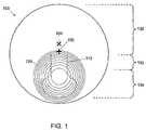
- FIG. 1shows a front view of a lens 100 having a progressive addition region and a diffractive addition region.
- FIGS. 2A and 2Bshow side views of the lens of FIG. 1 having a multi-order diffractive surface relief structure and the progressive addition region on the front and the back surfaces of the lens, respectively.
- FIGS. 3A and 3Bshow side views of the lens of FIG. 1 having a multi-order diffractive surface relief structure and the progressive addition region on the front and the back surfaces of the lens, respectively, and a thin film layer disposed between the front and the back surfaces of the lens.
- FIGS. 4A and 4Bshow side views of the lens of FIG. 1 having a diffractive wavefront splitting device optical region in optical communication with a multi-order diffractive surface relief structure.
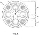
- FIG. 5shows a front view of the lens of FIG. 1 having a diffractive addition region that extends radially toward the peripheral edge of the lens.
- FIG. 6shows a side view of layers of a lens 200 including an electro-active diffractive addition region.
- FIG. 1shows a front view of a lens 100 having a progressive addition region 110 and a diffractive addition region 120 .
- the progressive addition region 110is a low add power PAL designed to provide a wearer with an optical power less than the wearer's needed near distance optical power correction.
- the add power of the PALmay be 50% of the required near distance optical power correction.
- the diffractive addition region 120is in optical communication with the progressive addition region.
- the diffractive addition regionat least partially, and preferably largely, overlaps the progressive addition region.
- the diffractive addition regionprovides the remaining optical power to provide the wearer's total needed near distance optical power correction.
- the diffractive addition regionmay be a multi-order diffractive (MOD) lens, e.g., as described by Faklis et al. (U.S. Pat. No. 5,589,982) and Morris et al. (U.S. Pat. No. 7,025,456), which are both incorporated herein by reference.
- MOD lenseshave a diffractive surface relief structure that focuses multiple wavelengths of light from multiple diffractive orders at a common point in space. MOD lenses are known to reduce the high levels of chromatic aberration typically associated with conventional diffractive lenses (especially for large optical powers).
- the lens 100includes a distance vision region 130 , an intermediate vision region 132 , and a near vision region 134 .
- the near vision regionmay be located, for example, where the progressive addition region has a maximum add power and coincides with the center of the diffractive addition region.
- the intermediate vision regionmay be located, for example, where the progressive addition region has less than its maximum add power and coincides with the center of the diffractive addition region.
- the distance vision regionmay be located, for example, where the progressive addition region and the diffractive addition region are absent.
- the lenshas a geometric (or physical) center 102 and a fitting point 104 . Typically, the distance vision region is located on the upper half of the viewing region of the lens above the fitting point.
- the fitting pointis designed to coincide with the location of the wearer's pupil and marks the start of the optical power progression (the progressive channel) from the distance vision region to the near vision region.
- the diffractive addition region 120(especially one having a MOD surface relief structure) is complex and the region is typically fabricated and embedded within the lens at the time of manufacture.
- the lensmay be a finished lens or an unfinished lens, and preferably, is a semi-finished lens blank.
- the lensmay be adjusted e.g., finished, in a lens laboratory to the wearer's prescription using methods known in the art.
- FIGS. 2A and 2Bshow side views of the lens 100 of FIG. 1 having a front piece 160 and a back piece 170 forming from the front (convex) and back (concave) surfaces, respectively.
- FIG. 2Ahas a progressive addition region 112 disposed on the front (convex) surface of the front piece 160 of the lens.
- FIG. 2Bhas a progressive addition region 114 disposed on the back (concave) surface of the back piece 170 of the lens.
- the lensmay have progressive addition regions disposed on both the front and back surfaces of the lens.
- the front surface progressive addition region 112 of FIG. 2A having a portion of progressive optical powermay be combined with the back surface progressive addition region 114 FIG. 2B having a portion of progressive optical power to form a lens having the total progressive optical power.
- the front surface progressive addition region 112 of FIG. 2Ais formed at the time of lens blank manufacture (e.g., by casting or molding).
- the back surface progressive addition region 114 of FIG. 2Bis typically formed at the time of prescription surfacing (e.g., by means of free-forming technology).
- the lens 100has a diffractive addition region 120 disposed between the inner surfaces of the front and back pieces 160 and 170 .
- the diffractive addition regionhas a MOD surface relief structure 140 .
- the MOD surface relief structuremay be formed integral to the inner surfaces of one or both of the front and the back pieces.
- the front and back piecesmay be manufactured by many methods known in the art, for example, by casting resin, injection molding from a thermo-plastic, or diamond turning. For example, a high precision machining technique, e.g., a single point diamond turning may be used to fabricate an inverse topological profile of the MOD surface relief structure onto a surface of a casting or molding tool, from which one or both of the front and back pieces are manufactured.
- the front and back piecesmay be made separately and then joined together with an adhesive. Alternatively, one of the pieces is made first and then the other piece is cast or molded thereonto.
- the front piece 160 of the lenshas a first refractive index, n 1
- the back piece 170 of the lenshas a second refractive index, n 2 , different from the first refractive index.
- the difference in refractive index between the two materialsprovides a phase retardation of incident optical wavefronts propagating across the MOD surface relief structure such that a high focusing efficiency (i.e. diffraction efficiency) is achieved, e.g., as described in Morris et. al., U.S. Pat. No. 7,025,456.
- FIGS. 3A and 3Bshow side views of the lens 100 of FIG. 1 having a multi-order diffractive surface relief structure and the progressive addition region 110 on the front and the back surfaces of the lens, respectively, and a thin film layer 180 disposed between the front piece 160 and the back piece 170 of the lens.
- the thin film layer 180may have the MOD surface relief structure 140 in certain embodiments of the invention.
- the thin film layermay be composed of transparent material having a refractive index, n 3 .
- the refractive indices, n 1 and n 2 , of the front and back pieces 160 and 170may be the same or different.
- the refractive index, n 3 , of the thin film layer having the MOD surface relief structuremust be different from either of the refractive indices, n 1 and n 2 , of the front and back pieces. The difference in the refractive indices in combination with the proper profile of the MOD surface relief structure causes the lens to have a high focusing efficiency.
- the thin film layermay be, for example, embossed, stamped, cast, or molded with the MOD surface relief structure, as is well known in the art.
- the thin film layermay then be embedded into the lens, e.g., in a manner similar to that used to embed polarizing films to make polarized sun lenses.
- the inner surface of one or both of the front and/or back pieces of the lensmay be fabricated with the MOD surface relief structure.
- An uncured (e.g., liquid) optical resin or adhesivemay be injected between the pieces of the lens. The injected material may be cured to solidify and form the thin film layer.
- FIGS. 4A and 4Bshow side views of the lenses 100 of FIG. 1 , having a wavefront splitting device (WSD) surface relief structure 190 and the MOD surface relief structure 140 .
- the WSD surface relief structure and the MOD surface relief structureare in optical communication.
- the WSD surface relief structureis, e.g., as described in U.S. Pat. No. 7,025,456 to Morris et al.
- the WSD surface relief structure 190has a surface relief diffractive profile that splits the energy of an incident wavefront equally into a predetermined number of diffraction orders, each with a distinct optical power (i.e., focal length).
- a wavefront propagating across the WSD surface relief structuremay have 50% of its energy diffracted into a first diffractive order corresponding to a first optical power and the other 50% of its energy diffracted into a second diffractive order corresponding to a second optical power.
- the WSD surface relief structure formed within the lensmay provide two distinct optical powers, e.g., +1.00 diopters (D) and ⁇ 1.00 D.
- the wavefrontpropagates across the MOD surface relief structure 140 .
- the optical power resulting from each diffractive orderis the sum of the optical power associated with the diffractive order generated by the WSD surface relief structure and the optical power of the MOD surface relief structure.
- the MOD surface relief structuremay provide +2.00 D of optical power.
- the optical powers of +1.00 D and ⁇ 1.00 D corresponding to the diffractive orders generated by the WSD surface relief structure, in combination with +2.00 D of optical power provided by the MOD surface relief structurewill provide a total of +3.00 D and +1.00 D of optical power, respectively.
- a wavefrontmay propagate across the MOD surface relief structure and the WSD surface relief structure in any order (e.g., propagating across the MOD first and the WSD second, or visa versa) with the same result.
- the combined MOD and WSD surface relief structuresare in optical communication with the progressive addition regions 112 and/or 114 , respectively.
- the combined MOD and WSD surface relief structuresprovide multiple images, each having different optical powers, while the progressive addition region provides additional optical power, which increases smoothly and continuously over the length of the progressive channel.
- the MOD surface relief structure 140may be replaced with the combined MOD and WSD surface relief structures of FIGS. 4A and 4B .
- the MOD and WSD surface relief structuresare constructed on the same surface.
- the MOD and WSD surface relief structuresmay be embossed, stamped, cast, or molded, on opposite surfaces of (as shown in FIGS. 4A and 4B ) or together on the same surface (not shown) of the thin film layer.
- the MOD and WSD surface relief structuresare fabricated on the (same or opposite) inner surfaces of the front and/or back pieces 160 and 170 of the lens.
- the MOD and WSD surface relief structuresmay be located below the fitting point of the progressive addition regions.
- the back (concave) surface of the lens(on the back of the back piece 170 in FIGS. 2A , 2 B, 3 A 3 B, 4 A and 4 B, and not shown in FIG. 1 ) may be ground and polished or free-formed, to provide any additional (sphere and/or cylinder) correction needed to achieve the wearer's far distance optical power correction.
- FIG. 5shows a front view of the lens 100 having a diffractive addition region 150 that extends radially toward the peripheral edge of the lens.
- the diffractive addition regionmay cover an entire surface of the lens (internal and/or external).
- the diffractive addition regionmay provide optical power in each of the distance, intermediate, and near vision regions 130 , 132 , and 134 .
- the diffractive addition regionmay provide one power for distance vision and another power for near vision.
- the diffractivemay be located above the fitting point 104 of the low add power progressive addition region 110 .
- the diffractive addition region 150may be a MOD surface relief structure or combined MOD and WSD surface relief structures.
- the diffractive addition region 150having combined MOD and WSD surface relief structures, provides (either fully, or a portion of) a sphere distance correction of ⁇ 2.00 D, using one of the two or more optical powers of the MOD and WSD surface relief structures. Any remaining optical power for distance vision correction may be generated by refraction via the curvatures of the front and back optical surfaces of the lens. Additionally, correction of the ⁇ 0.75 D of cylindrical distance vision error may be generated by refraction via an astigmatic surface either ground and polished or free-formed into the back surface of the lens.
- correction of the +2.25 D of near vision errormay be split between the second of the two optical powers of the MOD and WSD surface relief structures (e.g., a +1.25 D contribution) and the progressive addition surface (e.g., a +1.00 D contribution).
- the progressive addition surfacecontributes only a portion (e.g., +1.00 D) of the total needed add power to limit the amount of blur and/or distortion generally associated with the progressive addition surface (especially for large total add powers).
- FIG. 6shows a side view of layers of an electro-active lens 200 having an electro-active diffractive addition region 202 for making the diffractive addition region in embodiments of the previous figures electro-active.
- the electro-active diffractive addition region 202may include transparent electrodes 204 and 206 , alignment layers 208 and 210 , electro-active material 212 , electrical insulating layers 209 and 211 , and drive electronics 214 .
- the diffractive addition regionmay be disposed between a front piece 160 and a back piece 170 of the lens.
- the diffractive addition regionmay be on optical communication with the MOD surface relief structure 140 , the WSD surface relief structure (not shown), or the combined MOD and WSD surface relief structures (not shown).
- each of the electro-active diffractive addition region 202 , transparent electrode 206 , the alignment layer 210 , the electrical insulating layer 211 , and the inner surface of the back piece 170conforms to the topological profile of the MOD surface relief structure 140 , the WSD surface relief structure (not shown) or the combined MOD+WSD surface relief structure topography (not shown).
- the electro-active material 212may include, for example, a nematic liquid crystal or a cholesteric liquid crystal (CLC).
- CLCis typically preferred, since the material may allow for the focusing of light having substantially any polarization state and is thereby termed, “polarization insensitive”, as is described in U.S. Ser. No. 12/018,048, filed on 22 Jan. 2008, entitled “Cholesteric Liquid Crystalline Material” and U.S. Pat. No. 5,712,721 to Large, which are both incorporated herein by reference.
- the CLChas a refractive index that changes between an average refractive index, n avg (e.g., approximately in a range of 1.62 to 1.70, and preferably 1.67) when no electrical potential is applied thereto, and an ordinary refractive index, n o (e.g., approximately in a range of 1.50 to 1.57, and preferably 1.52) when sufficient electrical potential is applied across the electrodes 204 and 206 .
- Other intermediate refractive indices, n, where n o ⁇ n ⁇ n avgmay be achieved when intermediate electrical potentials are applied to the CLC.
- the refractive index of the front and back pieces 160 and 170may be approximately equal to the average refractive index, n avg , of the CLC.
- n avgthe average refractive index
- the refractive index of the CLCmatches the refractive index of the front and back pieces, and the electro-active diffractive optical power region 202 contributes no optical power.
- Such a lensmay provide fail-safe operation (contributing zero additional optical power in the electrical off state).
- the refractive index of the CLCis approximately equal to the ordinary refractive index, n o .
- the ordinary refractive index of the CLCdoes not match the refractive index, n avg , of the front and back pieces of the lens. This mismatch is such that proper phase retardation results (e.g., in integer multiples of 2 ⁇ ), leading to a high diffraction efficiency of the lens.
- Each of the front and back pieces 160 and 170may include refractive front and back components 162 and 172 , respectively, to correct static refractive errors of the eye.
- Each of the front and back pieces 160 and 170may include a component 166 having a flat or plano surface topography and a component 176 having the MOD surface relief structure or the combined MOD and WSD surface relief structures (not shown).
- Adhesive layers 164 and 174may attach front component 162 to component 166 and back component 172 to component 176 , respectively.
- the progressive addition surface(not shown) may be formed on one or both of the front and/or back surfaces of the lens.
Landscapes
- Health & Medical Sciences (AREA)
- Ophthalmology & Optometry (AREA)
- Physics & Mathematics (AREA)
- General Health & Medical Sciences (AREA)
- General Physics & Mathematics (AREA)
- Optics & Photonics (AREA)
- Eyeglasses (AREA)
Abstract
Description
Claims (15)
Priority Applications (1)
| Application Number | Priority Date | Filing Date | Title |
|---|---|---|---|
| US12/118,226US7654667B2 (en) | 2007-05-10 | 2008-05-09 | Progressive addition lens operating in combination with a multi-order diffractive optic |
Applications Claiming Priority (2)
| Application Number | Priority Date | Filing Date | Title |
|---|---|---|---|
| US92434407P | 2007-05-10 | 2007-05-10 | |
| US12/118,226US7654667B2 (en) | 2007-05-10 | 2008-05-09 | Progressive addition lens operating in combination with a multi-order diffractive optic |
Publications (2)
| Publication Number | Publication Date |
|---|---|
| US20080278681A1 US20080278681A1 (en) | 2008-11-13 |
| US7654667B2true US7654667B2 (en) | 2010-02-02 |
Family
ID=39969205
Family Applications (1)
| Application Number | Title | Priority Date | Filing Date |
|---|---|---|---|
| US12/118,226Expired - Fee RelatedUS7654667B2 (en) | 2007-05-10 | 2008-05-09 | Progressive addition lens operating in combination with a multi-order diffractive optic |
Country Status (2)
| Country | Link |
|---|---|
| US (1) | US7654667B2 (en) |
| WO (1) | WO2008140795A1 (en) |
Cited By (17)
| Publication number | Priority date | Publication date | Assignee | Title |
|---|---|---|---|---|
| US20110007266A1 (en)* | 2007-03-29 | 2011-01-13 | Pixeloptics, Inc. | Multifocal lens having a progressive optical power region and a discontinuity |
| US20110194069A1 (en)* | 2007-03-07 | 2011-08-11 | Pixeloptics, Inc. | Multifocal Lens Having a Progressive Optical Power Region and Discontinuity |
| US8830408B2 (en) | 2008-04-11 | 2014-09-09 | Hpo Assets Llc | Electro-active diffractive lens and method for making the same |
| US9335563B2 (en) | 2012-08-31 | 2016-05-10 | Amo Groningen B.V. | Multi-ring lens, systems and methods for extended depth of focus |
| US9588396B2 (en) | 2012-02-07 | 2017-03-07 | Mitsui Chemicals, Inc. | Laser patterning of conductive films for electro-active lenses |
| US10613355B2 (en) | 2007-05-04 | 2020-04-07 | E-Vision, Llc | Moisture-resistant eye wear |
| US10613350B2 (en) | 2017-10-16 | 2020-04-07 | National Chiao Tung University | Electrically focus-tunable lens and eyewear including the same |
| US10624735B2 (en) | 2016-02-09 | 2020-04-21 | Amo Groningen B.V. | Progressive power intraocular lens, and methods of use and manufacture |
| US11061252B2 (en) | 2007-05-04 | 2021-07-13 | E-Vision, Llc | Hinge for electronic spectacles |
| US11156853B2 (en) | 2017-06-28 | 2021-10-26 | Amo Groningen B.V. | Extended range and related intraocular lenses for presbyopia treatment |
| US11262598B2 (en) | 2017-06-28 | 2022-03-01 | Amo Groningen, B.V. | Diffractive lenses and related intraocular lenses for presbyopia treatment |
| US11327210B2 (en) | 2017-06-30 | 2022-05-10 | Amo Groningen B.V. | Non-repeating echelettes and related intraocular lenses for presbyopia treatment |
| US11497599B2 (en) | 2017-03-17 | 2022-11-15 | Amo Groningen B.V. | Diffractive intraocular lenses for extended range of vision |
| US11523897B2 (en) | 2017-06-23 | 2022-12-13 | Amo Groningen B.V. | Intraocular lenses for presbyopia treatment |
| US11844689B2 (en) | 2019-12-30 | 2023-12-19 | Amo Groningen B.V. | Achromatic lenses and lenses having diffractive profiles with irregular width for vision treatment |
| US12204178B2 (en) | 2018-12-06 | 2025-01-21 | Amo Groningen B.V. | Diffractive lenses for presbyopia treatment |
| US12436411B2 (en) | 2010-07-02 | 2025-10-07 | E-Vision Optics, Llc | Moisture-resistant eye wear |
Families Citing this family (13)
| Publication number | Priority date | Publication date | Assignee | Title |
|---|---|---|---|---|
| JP5251517B2 (en)* | 2007-01-25 | 2013-07-31 | 株式会社ニコン | Eyeglass lenses |
| US7883207B2 (en)* | 2007-12-14 | 2011-02-08 | Pixeloptics, Inc. | Refractive-diffractive multifocal lens |
| US8587734B2 (en)* | 2009-03-06 | 2013-11-19 | The Curators Of The University Of Missouri | Adaptive lens for vision correction |
| US8857990B2 (en)* | 2010-03-31 | 2014-10-14 | Brett Spivey | Device and process for progressive addition lens design |
| DE102010051645B4 (en)* | 2010-11-17 | 2025-01-09 | Rodenstock Gmbh | Computer-implemented method for determining a diffractive grating, computer program product, storage medium, optical element, method and device for producing an optical element |
| US8827446B2 (en)* | 2011-03-10 | 2014-09-09 | Hpo Assets Llc | Electronic lens comprised of hybrid materials |
| US9242418B2 (en)* | 2011-11-16 | 2016-01-26 | Essilor International | Ophthalmic lens containing a fresnel surface and method for manufacturing same |
| EP2722694A1 (en) | 2012-10-17 | 2014-04-23 | Asociación Industrial de Óptica, Color e Imagen - AIDO | Multi-order diffractive optical element for concentration of broadband electromagnetic radiation |
| CN108351538A (en)* | 2015-11-19 | 2018-07-31 | 日本化药株式会社 | Glasses optical film and glasses functional membrane, glasses optical laminate and glasses with the glasses optical film |
| DE102015122302B4 (en) | 2015-12-18 | 2021-10-07 | tooz technologies GmbH | Ophthalmic optical element, glasses, head-mounted display device, computer-implemented method for designing an ophthalmic optical element, method for manufacturing an ophthalmic optical element and computer program product |
| CN111587396B (en)* | 2018-02-09 | 2022-08-05 | 三井化学株式会社 | Lens and method for manufacturing lens |
| WO2025014706A1 (en)* | 2023-07-07 | 2025-01-16 | University Of Houston System | Myopia control using corrected longitudinal chromatic aberration |
| CN119493291A (en)* | 2025-01-17 | 2025-02-21 | 上海卫康光学眼镜有限公司 | A new type of blue light blocking soft hydrophilic contact lens |
Citations (3)
| Publication number | Priority date | Publication date | Assignee | Title |
|---|---|---|---|---|
| US6270220B1 (en)* | 1998-06-18 | 2001-08-07 | Rotlex (1994) Ltd. | Multifocal lens |
| US6619799B1 (en) | 1999-07-02 | 2003-09-16 | E-Vision, Llc | Optical lens system with electro-active lens having alterably different focal lengths |
| US7093938B2 (en) | 2003-06-16 | 2006-08-22 | Apollo Optical Systems Llc | Bifocal multiorder diffractive lenses for vision correction |
- 2008
- 2008-05-09USUS12/118,226patent/US7654667B2/ennot_activeExpired - Fee Related
- 2008-05-12WOPCT/US2008/006024patent/WO2008140795A1/enactiveApplication Filing
Patent Citations (3)
| Publication number | Priority date | Publication date | Assignee | Title |
|---|---|---|---|---|
| US6270220B1 (en)* | 1998-06-18 | 2001-08-07 | Rotlex (1994) Ltd. | Multifocal lens |
| US6619799B1 (en) | 1999-07-02 | 2003-09-16 | E-Vision, Llc | Optical lens system with electro-active lens having alterably different focal lengths |
| US7093938B2 (en) | 2003-06-16 | 2006-08-22 | Apollo Optical Systems Llc | Bifocal multiorder diffractive lenses for vision correction |
Non-Patent Citations (1)
| Title |
|---|
| International Search Report for International Application No. PCT/US08/06024, completed Sep. 19, 2008, pp. 1-7. |
Cited By (30)
| Publication number | Priority date | Publication date | Assignee | Title |
|---|---|---|---|---|
| US20110194069A1 (en)* | 2007-03-07 | 2011-08-11 | Pixeloptics, Inc. | Multifocal Lens Having a Progressive Optical Power Region and Discontinuity |
| US8308295B2 (en) | 2007-03-07 | 2012-11-13 | Pixeloptics, Inc. | Multifocal lens having a progressive optical power region and discontinuity |
| US8434865B2 (en) | 2007-03-07 | 2013-05-07 | Pixeloptics, Inc. | Multifocal lens having a progressive optical power region and a discontinuity |
| US20110043752A1 (en)* | 2007-03-29 | 2011-02-24 | Pixeloptics, Inc. | Multifocal Lens Having A Progressive Optical Power Region and a Discontinuity |
| US8092016B2 (en)* | 2007-03-29 | 2012-01-10 | Pixeloptics, Inc. | Multifocal lens having a progressive optical power region and a discontinuity |
| US20110007266A1 (en)* | 2007-03-29 | 2011-01-13 | Pixeloptics, Inc. | Multifocal lens having a progressive optical power region and a discontinuity |
| US9033494B2 (en) | 2007-03-29 | 2015-05-19 | Mitsui Chemicals, Inc. | Multifocal lens having a progressive optical power region and a discontinuity |
| US10613355B2 (en) | 2007-05-04 | 2020-04-07 | E-Vision, Llc | Moisture-resistant eye wear |
| US11061252B2 (en) | 2007-05-04 | 2021-07-13 | E-Vision, Llc | Hinge for electronic spectacles |
| US11586057B2 (en) | 2007-05-04 | 2023-02-21 | E-Vision, Llc | Moisture-resistant eye wear |
| US8830408B2 (en) | 2008-04-11 | 2014-09-09 | Hpo Assets Llc | Electro-active diffractive lens and method for making the same |
| US10197815B2 (en) | 2008-05-13 | 2019-02-05 | Amo Groningen B.V. | Multi-ring lens, systems and methods for extended depth of focus |
| US12436411B2 (en) | 2010-07-02 | 2025-10-07 | E-Vision Optics, Llc | Moisture-resistant eye wear |
| US9588396B2 (en) | 2012-02-07 | 2017-03-07 | Mitsui Chemicals, Inc. | Laser patterning of conductive films for electro-active lenses |
| US11022815B2 (en) | 2012-08-31 | 2021-06-01 | Amo Groningen B.V. | Multi-ring lens, systems and methods for extended depth of focus |
| US12158638B2 (en) | 2012-08-31 | 2024-12-03 | Amo Groningen B.V. | Multi-ring lens, systems and methods for extended depth of focus |
| US9335563B2 (en) | 2012-08-31 | 2016-05-10 | Amo Groningen B.V. | Multi-ring lens, systems and methods for extended depth of focus |
| US11116624B2 (en) | 2016-02-09 | 2021-09-14 | Amo Groningen B.V. | Progressive power intraocular lens, and methods of use and manufacture |
| US10624735B2 (en) | 2016-02-09 | 2020-04-21 | Amo Groningen B.V. | Progressive power intraocular lens, and methods of use and manufacture |
| US12257144B2 (en) | 2016-02-09 | 2025-03-25 | Amo Groningen B.V. | Progressive power intraocular lens, and methods of use and manufacture |
| US11497599B2 (en) | 2017-03-17 | 2022-11-15 | Amo Groningen B.V. | Diffractive intraocular lenses for extended range of vision |
| US11523897B2 (en) | 2017-06-23 | 2022-12-13 | Amo Groningen B.V. | Intraocular lenses for presbyopia treatment |
| US11262598B2 (en) | 2017-06-28 | 2022-03-01 | Amo Groningen, B.V. | Diffractive lenses and related intraocular lenses for presbyopia treatment |
| US11914229B2 (en) | 2017-06-28 | 2024-02-27 | Amo Groningen B.V. | Diffractive lenses and related intraocular lenses for presbyopia treatment |
| US11573433B2 (en) | 2017-06-28 | 2023-02-07 | Amo Groningen B.V. | Extended range and related intraocular lenses for presbyopia treatment |
| US11156853B2 (en) | 2017-06-28 | 2021-10-26 | Amo Groningen B.V. | Extended range and related intraocular lenses for presbyopia treatment |
| US11327210B2 (en) | 2017-06-30 | 2022-05-10 | Amo Groningen B.V. | Non-repeating echelettes and related intraocular lenses for presbyopia treatment |
| US10613350B2 (en) | 2017-10-16 | 2020-04-07 | National Chiao Tung University | Electrically focus-tunable lens and eyewear including the same |
| US12204178B2 (en) | 2018-12-06 | 2025-01-21 | Amo Groningen B.V. | Diffractive lenses for presbyopia treatment |
| US11844689B2 (en) | 2019-12-30 | 2023-12-19 | Amo Groningen B.V. | Achromatic lenses and lenses having diffractive profiles with irregular width for vision treatment |
Also Published As
| Publication number | Publication date |
|---|---|
| US20080278681A1 (en) | 2008-11-13 |
| WO2008140795A1 (en) | 2008-11-20 |
Similar Documents
| Publication | Publication Date | Title |
|---|---|---|
| US7654667B2 (en) | Progressive addition lens operating in combination with a multi-order diffractive optic | |
| US7883207B2 (en) | Refractive-diffractive multifocal lens | |
| US20250116887A1 (en) | Lens element | |
| US8092016B2 (en) | Multifocal lens having a progressive optical power region and a discontinuity | |
| US8210677B2 (en) | Patch for modification of the power of an optical component | |
| US7744215B2 (en) | Multiple layer multifocal composite lens | |
| US8287124B2 (en) | Opthalmic lenses having reduced base out prism | |
| TWI435139B (en) | Static progressive surface region in optical communication with a dynamic optic | |
| US20090091818A1 (en) | Electro-active insert | |
| KR20000071332A (en) | Progressive addition lenses having regressive surfaces | |
| AU2013228002B2 (en) | Multiple layer multifocal composite lens | |
| CA2680870C (en) | Multifocal lens having a progressive optical power region and a discontinuity | |
| WO2009079342A1 (en) | Refractive-diffractive multifocal lens | |
| AU2008338597B2 (en) | Multiple layer multifocal composite lens | |
| CN120112837A (en) | Electrically switchable liquid crystal cell, contact lens and related methods | |
| HK1137056B (en) | Static progressive surface region in optical communication with a dynamic optic |
Legal Events
| Date | Code | Title | Description |
|---|---|---|---|
| AS | Assignment | Owner name:PIXELOPTICS INC.,VIRGINIA Free format text:ASSIGNMENT OF ASSIGNORS INTEREST;ASSIGNORS:BLUM, RONALD D.;KOKONASKI, WILLIAM;HADDOCK, JOSHUA N.;REEL/FRAME:021224/0564 Effective date:20080604 Owner name:PIXELOPTICS INC., VIRGINIA Free format text:ASSIGNMENT OF ASSIGNORS INTEREST;ASSIGNORS:BLUM, RONALD D.;KOKONASKI, WILLIAM;HADDOCK, JOSHUA N.;REEL/FRAME:021224/0564 Effective date:20080604 | |
| STCF | Information on status: patent grant | Free format text:PATENTED CASE | |
| FPAY | Fee payment | Year of fee payment:4 | |
| AS | Assignment | Owner name:HPO ASSETS LLC, CONNECTICUT Free format text:ASSIGNMENT OF ASSIGNORS INTEREST;ASSIGNOR:PIXELOPTICS, INC.;REEL/FRAME:033240/0931 Effective date:20140131 | |
| AS | Assignment | Owner name:MITSUI CHEMICALS, INC., JAPAN Free format text:ASSIGNMENT OF ASSIGNORS INTEREST;ASSIGNOR:HPO ASSETS LLC;REEL/FRAME:034099/0969 Effective date:20140922 | |
| FEPP | Fee payment procedure | Free format text:PAYOR NUMBER ASSIGNED (ORIGINAL EVENT CODE: ASPN); ENTITY STATUS OF PATENT OWNER: LARGE ENTITY | |
| FPAY | Fee payment | Year of fee payment:8 | |
| FEPP | Fee payment procedure | Free format text:MAINTENANCE FEE REMINDER MAILED (ORIGINAL EVENT CODE: REM.); ENTITY STATUS OF PATENT OWNER: LARGE ENTITY | |
| LAPS | Lapse for failure to pay maintenance fees | Free format text:PATENT EXPIRED FOR FAILURE TO PAY MAINTENANCE FEES (ORIGINAL EVENT CODE: EXP.); ENTITY STATUS OF PATENT OWNER: LARGE ENTITY | |
| STCH | Information on status: patent discontinuation | Free format text:PATENT EXPIRED DUE TO NONPAYMENT OF MAINTENANCE FEES UNDER 37 CFR 1.362 | |
| FP | Lapsed due to failure to pay maintenance fee | Effective date:20220202 |