US7654102B2 - Air treatment system for refrigerated appliance - Google Patents
Air treatment system for refrigerated applianceDownload PDFInfo
- Publication number
- US7654102B2 US7654102B2US11/654,442US65444207AUS7654102B2US 7654102 B2US7654102 B2US 7654102B2US 65444207 AUS65444207 AUS 65444207AUS 7654102 B2US7654102 B2US 7654102B2
- Authority
- US
- United States
- Prior art keywords
- air
- cartridge
- treatment system
- appliance
- air duct
- Prior art date
- Legal status (The legal status is an assumption and is not a legal conclusion. Google has not performed a legal analysis and makes no representation as to the accuracy of the status listed.)
- Active, expires
Links
- 230000007246mechanismEffects0.000claimsabstractdescription24
- 230000008878couplingEffects0.000claimsabstractdescription21
- 238000010168coupling processMethods0.000claimsabstractdescription21
- 238000005859coupling reactionMethods0.000claimsabstractdescription21
- CBENFWSGALASAD-UHFFFAOYSA-NOzoneChemical compound[O-][O+]=OCBENFWSGALASAD-UHFFFAOYSA-N0.000claimsdescription7
- GWEVSGVZZGPLCZ-UHFFFAOYSA-NTitan oxideChemical compoundO=[Ti]=OGWEVSGVZZGPLCZ-UHFFFAOYSA-N0.000claimsdescription7
- 239000003054catalystSubstances0.000claimsdescription5
- 238000004891communicationMethods0.000claimsdescription5
- 239000004408titanium dioxideSubstances0.000claimsdescription3
- 230000005540biological transmissionEffects0.000claims1
- 238000004887air purificationMethods0.000description5
- 238000001914filtrationMethods0.000description5
- 235000013305foodNutrition0.000description5
- 238000000746purificationMethods0.000description4
- 238000012986modificationMethods0.000description3
- 230000004048modificationEffects0.000description3
- 238000011144upstream manufacturingMethods0.000description3
- 238000010276constructionMethods0.000description2
- 239000000463materialSubstances0.000description2
- 238000000034methodMethods0.000description2
- 239000012855volatile organic compoundSubstances0.000description2
- 241000894006BacteriaSpecies0.000description1
- VGGSQFUCUMXWEO-UHFFFAOYSA-NEtheneChemical compoundC=CVGGSQFUCUMXWEO-UHFFFAOYSA-N0.000description1
- 239000005977EthyleneSubstances0.000description1
- 239000003086colorantSubstances0.000description1
- 230000003750conditioning effectEffects0.000description1
- 238000013461designMethods0.000description1
- 239000012530fluidSubstances0.000description1
- 235000013611frozen foodNutrition0.000description1
- 230000001590oxidative effectEffects0.000description1
- 239000002245particleSubstances0.000description1
- 239000008188pelletSubstances0.000description1
- 239000002861polymer materialSubstances0.000description1
- 230000008569processEffects0.000description1
- 238000005057refrigerationMethods0.000description1
- 230000000717retained effectEffects0.000description1
- 238000012552reviewMethods0.000description1
- 238000005201scrubbingMethods0.000description1
- 239000007787solidSubstances0.000description1
- 238000006467substitution reactionMethods0.000description1
- 238000012546transferMethods0.000description1
- -1ultraviolet lightChemical compound0.000description1
- 230000000007visual effectEffects0.000description1
- 239000002699waste materialSubstances0.000description1
Images


Classifications
- F—MECHANICAL ENGINEERING; LIGHTING; HEATING; WEAPONS; BLASTING
- F25—REFRIGERATION OR COOLING; COMBINED HEATING AND REFRIGERATION SYSTEMS; HEAT PUMP SYSTEMS; MANUFACTURE OR STORAGE OF ICE; LIQUEFACTION SOLIDIFICATION OF GASES
- F25D—REFRIGERATORS; COLD ROOMS; ICE-BOXES; COOLING OR FREEZING APPARATUS NOT OTHERWISE PROVIDED FOR
- F25D17/00—Arrangements for circulating cooling fluids; Arrangements for circulating gas, e.g. air, within refrigerated spaces
- F25D17/04—Arrangements for circulating cooling fluids; Arrangements for circulating gas, e.g. air, within refrigerated spaces for circulating air, e.g. by convection
- F25D17/042—Air treating means within refrigerated spaces
- F—MECHANICAL ENGINEERING; LIGHTING; HEATING; WEAPONS; BLASTING
- F25—REFRIGERATION OR COOLING; COMBINED HEATING AND REFRIGERATION SYSTEMS; HEAT PUMP SYSTEMS; MANUFACTURE OR STORAGE OF ICE; LIQUEFACTION SOLIDIFICATION OF GASES
- F25D—REFRIGERATORS; COLD ROOMS; ICE-BOXES; COOLING OR FREEZING APPARATUS NOT OTHERWISE PROVIDED FOR
- F25D2317/00—Details or arrangements for circulating cooling fluids; Details or arrangements for circulating gas, e.g. air, within refrigerated spaces, not provided for in other groups of this subclass
- F25D2317/04—Treating air flowing to refrigeration compartments
- F25D2317/041—Treating air flowing to refrigeration compartments by purification
- F25D2317/0417—Treating air flowing to refrigeration compartments by purification using an UV-lamp
Definitions
- the present inventionrelates to an air treatment system for a refrigerated appliance. More specifically, the present invention relates to an air treatment system for a refrigerator having a removable/replaceable/rechargeable cartridge accessible from a refrigerator compartment.
- Refrigerated appliances having one or more refrigerator compartments and/or freezer compartmentsare generally known. It is generally known to provide an air treatment systems for such appliance.
- Known air treatment systemstypically include a purification/filtration element and a fan to force air through the purification/filtration element. Also, known systems are typically are mounted on a wall inside the food compartment of the refrigerator.
- such known air treatment systemshave several disadvantages including waste of storage space, limited performance due to inadequate access to air and air flow (especially when the food storage space is relatively full), and having to pass a power cord through the refrigerator wall to power the fan. It is also known to provide a purification/filtration element that uses a combination of titanium dioxide, ultraviolet light, and ozone. However, use of ozone in such a combination tends to degrade or be harmful with the material around it and to food in the storage compartment.
- an integrated air treatment system for a refrigeratorIt would also be advantageous to provide an air treatment system that is integrated into the airflow upstream or downstream of the evaporator. It would further be advantageous to provide an air treatment system that only treats (e.g., purifies, filters, etc.) a portion of the air passing from the evaporator to the evaporator fan. It would further be advantageous to provide an air treatment system with a cartridge that is accessible from the food storage compartment to be removed, replaced, recharged, repaired, maintained, or the like. It would further be advantageous to provide an air treatment system with purification/filtering element that does not use ozone. It would be desirable to provide for an air treatment system having one or more of these or other advantageous features. To provide an inexpensive, reliable, and widely adaptable air treatment system that avoids the above-referenced and other problems would represent a significant advance in the art.
- the present inventionrelates to an appliance comprising an enclosure defining a cooled space; an air duct in communication with the enclosure; an evaporator configured to cool air in the air duct; a fan configured to move air between the air duct and the cooled space; and an air treatment system at least partially located in the air duct. A portion of the air passing through the air duct passes through the air treatment system and a remainder of the air passes through the air duct without passing through the air treatment system.
- the present inventionfurther relates to a refrigerated appliance comprising an enclosure defining a cooled space; an air duct in communication with the enclosure; an evaporator configured to cool air in the air duct; an evaporator fan configured to move air from the air duct into the cooled space; and an air treatment system at least partially located in the air duct and accessible from the cooled space through an access panel.
- the present inventionfurther relates to a refrigerated appliance comprising an enclosure defining a cooled space, an air duct in communication with the enclosure, a fan configured to move air from the air duct into the cooled space, and an air treatment system at least partially located in the air duct and having a cartridge configured to treat air utilizing ultraviolet light in combination with a titanium dioxide coated catalyst and without the use of ozone.
- the present inventionfurther relates to various features and combinations of features shown and described in the disclosed embodiments.
- Other ways in which the objects and features of the disclosed embodiments are accomplishedwill be described in the following specification or will become apparent to those skilled in the art after they have read this specification. Such other ways are deemed to fall within the scope of the disclosed embodiments if they fall within the scope of the claims which follow.
- FIG. 1is a perspective view of a refrigerator including an air purification system according to an exemplary embodiment.
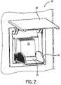
- FIG. 2is a more detailed perspective view of the air purification system in FIG. 1 in an open position according to an exemplary embodiment.
- FIG. 3is a front elevation view of a portion of the refrigerator in FIG. 1 with a portion of the inner wall hidden showing the airflow through the air duct between the evaporator and the evaporator fan according to an exemplary embodiment.
- FIG. 4is an exploded view of the air purification system in FIG. 1 according to an exemplary embodiment.
- FIG. 5is an exploded view of the filter cartridge in FIG. 4 according to an exemplary embodiment.
- FIGS. 6A and 6Bare side elevation views of the air purification system in FIG. 1 in an first or closed position and a second or open position.
- FIGS. 7A and 7Bare cross-section views of the air purification system in FIG. 1 in an first or closed position and a second or open position.
- FIG. 1shows an appliance as a refrigerator 10 according to a preferred embodiment.
- Refrigerator 10includes an enclosure 12 , an evaporator 22 , an evaporator fan 24 , and an air treatment system 30 .
- Enclosure 12forms the main body of refrigerator 10 and includes an insulated outer wall 14 and an inner wall 16 (e.g., cold plate, etc.).
- Enclosure 12may be a refrigerator component (e.g., for fresh foods) or a freezer compartment (e.g., for frozen foods).
- Outer wall 14 and inner wall 16are at least partially separated by an air duct 18 (e.g., passage, space, volume, passageway, etc.).
- Inner wall 16defines a cooled area or compartment 20 that is configured to receive items to be kept cooler than the outside environment.
- Cooled area 20is cooled by a refrigeration system that includes at least a compressor, an evaporator 22 , and a first or evaporator fan 24 .
- evaporator 22is disposed at least partially in air duct 18 and generally towards the bottom of enclosure 12 .
- Evaporator fan 24is disposed towards the top of enclosure 12 and draws air from evaporator 22 , upwards through air duct 18 and into cooled compartment 20 .
- air treatment system 30is disposed between evaporator 22 and evaporator fan 24 and at least partially within air duct 18 .
- Air treatment system 30is configured treat (e.g., purify, filter scrub, freshen, etc.) air inside refrigerator by oxidizing odor, bacteria, ethylene, volatile organic compounds (VOC's) or other undesirable particles without the use of ozone.
- air treatment system 30includes a removable filter cartridge or module 32 that is received by a base 34 with the aid of a mounting mechanism 36 .
- a second fan 35is provided to facilitate directing airflow into air treatment system 30 .
- An access panel 38is provided on inner wall 16 to allow access to air treatment system 30 from cooled compartment 20 .
- a mounting panel 39is coupled to outer wall 14 and provides a mounting surface for base 34 and/or other components of air treatment system 30 .
- air treatment system 30is shown in FIGS. 1 and 2 as being disposed towards one side of enclosure 12 and towards the top of enclosure 12 it should be understood that air treatment system 30 may be provided in a wide variety of locations between evaporator 22 and evaporator fan 24 .
- a majority of air treatment system 30is disposed within air duct 18 so that it does not occupy substantial space within cooled compartment 20 or extend a substantial amount outside outer wall 14 .
- Air treatment system 30is shown as being located downstream of evaporator 22 (e.g., between evaporator 22 and fan 24 ).
- the air treatment systemmay be in any of a variety of locations in the airflow (e.g., upstream) and the evaporator fan may be located upstream of the evaporator (e.g., to push or blow air across the evaporator).
- filter cartridge 32is a removable member that is configured to filter or treat air passing through it.
- Filter cartridge 32includes an outer housing 40 that forms a passage that is generally aligned with the air flow in air duct 18 .
- housing 40includes a front 80 , a back, 82 , a bottom 84 , and a top 86 .
- Front 80 and back 82are generally solid members while bottom 84 and top 86 includes a plurality of slots or openings that allow air to pass through housing 40 .
- a catalyst and a lamp 44are disposed within housing.
- the catalyst(not shown) is a plurality of hollow members (e.g., pellets, pieces, tubes, etc.) that are at least partially coated with titanium dioxide (T i O 2 ).
- the hollow membersare large enough to be retained within housing by bottom 84 and top 86 panels.
- Lamp 44is a light source that emits ultraviolet light (e.g., UV a, UV b, UV c, etc.). According to an exemplary embodiment, lamp 44 uses a 5 Watt (W) bulb (e.g., compact fluorescent). Alternatively, the bulb may be of any variety of sizes, power outputs or the like based on the desired performance of the environment. Lamp 44 cooperates with the catalyst to purify air passing through filter cartridge. Lamp 44 is coupled to an electrical contact 46 that is provided on the bottom of filter cartridge 32 . Electrical contact 46 is configured to interface with a corresponding electrical interface 52 on base 34 to provide power to lamp 44 . Ultraviolet light may weaken or otherwise damage polymer materials.
- Housing 40is configured to substantially enclose lamp 44 so that most of the ultraviolet light emitted by lamp 44 does not escape housing 40 .
- Access panel 38 and/or coupling mechanism 36are also configured (e.g., shaped, positioned, orientated, etc.) to inhibit or prevent ultraviolet light from exiting the air treatment system.
- Filter cartridge 32is removable and is able to be periodically replaced. According to various exemplary embodiments, spent filter cartridges may be disposed, recycled, or recharged. According to a preferred embodiment, lamp 44 does not provide a visible light outside of cartridge 32 .
- Filter cartridge 32is coupled to base 34 .
- Base 34includes a receptacle or socket 50 that is configured to receive a portion of filter cartridge 32 and an electrical contact 52 within receptacle 50 that interfaces with electrical contact 46 to provide electrical power to lamp 44 .
- Base 34further forms an air duct 54 that allows air from air duct 18 to pass through base 34 and into filter cartridge 32 .
- filter cartridge 32is coupled to base 34 when it is fully seated within base 34 .
- a second fan 35is provided below base 34 to further direct air from air duct 18 into air treatment system 30 . As shown in FIG. 3 , air treatment system 30 only treats a portion of the air passing through air duct 18 . Since air is being fairly continually circulated through air duct 18 , all or substantially all of the air in refrigerator 10 will pass through air treatment system 30 over time.
- Second fan 35 and base 34are coupled to an external power source to provide electrical power to second fan 35 , lamp 44 , and any other components that may be included and draw electrical power (e.g., sensors, lights, etc.).
- electrical contacts 46 and 52transfer electrical power between the refrigerator 10 and filter cartridge 32 .
- the same or additional electrical contactsmay transmit data between filter cartridge 32 and refrigerator 10 (e.g., data related to the life and/or performance of the filter cartridge).
- a mounting or coupling mechanism 36is provided to facilitate the coupling of filter cartridge 32 to base 34 .
- Coupling mechanism 36is coupled to base 34 at pivot points 60 and includes a lever 62 (e.g., release handle, lever, user interface, grip, etc.) with cam surfaces 64 .
- Coupling mechanism 36is moveable (e.g., pivot, rotate, swivel, swing, etc.) between a first or engaged position in which filter cartridge 32 is coupled to base 34 and a second or disengaged position in which filter cartridge 32 is released from base 34 .
- a usermay manipulate coupling mechanism 36 from cooled compartment 20 through an opening in inner wall 16 using lever 62 provided on a distal end of coupling mechanism 36 generally opposite of pivot points 60 .
- Cam surfaces 64are provided on coupling mechanism 36 and interface with projections 48 (e.g., protrusions, pegs, knobs, etc.) to engage and disengage filter cartridge 32 and base 34 .
- filter cartridge 32When coupling mechanism 36 is in a disengaged position (as shown in FIGS. 6B and 7B ), filter cartridge 32 may be inserted into base 34 . In this position, filter cartridge 32 is not coupled to base 34 and projections 48 sit in first seat 66 . As coupling mechanism 36 is moved from an open position to a closed position, projections 48 ride along cam surfaces 64 until they are received in second seats 68 . Filter cartridge 32 is pushed into a “snap-fit” with base 34 when coupling mechanism 36 is in a closed position and projections 48 are engaged with second seats 68 (as shown in FIGS. 6A and 7A ).
- Coupling mechanism 36ensures that filter cartridge is properly aligned with base 34 and fully seated in base 34 so that electrical contacts 46 and 52 are engaged. If filter cartridge 32 is not coupled properly to base 34 , coupling mechanism 36 will remain in a position intermediate between the open position and closed position. This will prevent access panel 38 from closing and provide a visual indication that filter cartridge 32 is not properly installed.
- a usegrasps lever 62 and pulls coupling mechanism 36 to an open position. Projections 48 engage cam surfaces 64 and disengage filter cartridge 32 from base 34 . When coupling mechanism 36 is in a disengaged position it lifts and presents filter cartridge 32 (e.g., to a user desiring to remove, check, replace, etc. filter cartridge 32 ).
- Access panel 38(e.g., door, hatch, etc.) is provided on inner surface of inner wall 16 .
- Access panel 38is pivotably coupled to inner wall 16 and is moveable between a first or open position in which air treatment system 30 is accessible from cooled compartment and a second or closed position in which air treatment system 30 is generally concealed from view.
- Access panel 38includes an interface 70 (e.g., aperture, opening, detent, etc.) that facilitates the opening of access panel 38 by a user.
- access panel 38pivots on hinges that are disposed along the upper edge of access panel 38 .
- access panelmay pivot along one of the sides or along the bottom edge.
- the term “coupled”shall mean the joining of two members directly or indirectly to one another. Such joining may be stationary in nature or movable in nature. Such joining may be achieved with the two members or the two members and any additional intermediate members being integrally formed as a single unitary body with one another or with the two members or the two members and any additional intermediate member being attached to one another. Such joining may be permanent in nature or alternatively may be removable or releasable in nature. Such joining may also relate to mechanical, fluid, or electrical relationship between the two components.
Landscapes
- Engineering & Computer Science (AREA)
- Chemical & Material Sciences (AREA)
- Combustion & Propulsion (AREA)
- Physics & Mathematics (AREA)
- Mechanical Engineering (AREA)
- Thermal Sciences (AREA)
- General Engineering & Computer Science (AREA)
- Cold Air Circulating Systems And Constructional Details In Refrigerators (AREA)
Abstract
Description
Claims (23)
Priority Applications (2)
| Application Number | Priority Date | Filing Date | Title |
|---|---|---|---|
| US11/654,442US7654102B2 (en) | 2007-01-17 | 2007-01-17 | Air treatment system for refrigerated appliance |
| US11/801,004US7824480B2 (en) | 2007-01-17 | 2007-05-07 | Air treatment system |
Applications Claiming Priority (1)
| Application Number | Priority Date | Filing Date | Title |
|---|---|---|---|
| US11/654,442US7654102B2 (en) | 2007-01-17 | 2007-01-17 | Air treatment system for refrigerated appliance |
Related Child Applications (1)
| Application Number | Title | Priority Date | Filing Date |
|---|---|---|---|
| US11/801,004Continuation-In-PartUS7824480B2 (en) | 2007-01-17 | 2007-05-07 | Air treatment system |
Publications (2)
| Publication Number | Publication Date |
|---|---|
| US20080168788A1 US20080168788A1 (en) | 2008-07-17 |
| US7654102B2true US7654102B2 (en) | 2010-02-02 |
Family
ID=39616730
Family Applications (1)
| Application Number | Title | Priority Date | Filing Date |
|---|---|---|---|
| US11/654,442Active2028-01-05US7654102B2 (en) | 2007-01-17 | 2007-01-17 | Air treatment system for refrigerated appliance |
Country Status (1)
| Country | Link |
|---|---|
| US (1) | US7654102B2 (en) |
Cited By (11)
| Publication number | Priority date | Publication date | Assignee | Title |
|---|---|---|---|---|
| US9179703B2 (en) | 2012-08-28 | 2015-11-10 | Sensor Electronic Technology, Inc. | Ultraviolet system for disinfection |
| US9724441B2 (en) | 2012-08-28 | 2017-08-08 | Sensor Electronic Technology, Inc. | Storage device including target UV illumination ranges |
| US9750830B2 (en) | 2012-08-28 | 2017-09-05 | Sensor Electronic Technology, Inc. | Multi wave sterilization system |
| US9795699B2 (en) | 2012-08-28 | 2017-10-24 | Sensor Electronic Technology, Inc. | Storage device including target UV illumination ranges |
| US9919068B2 (en) | 2012-08-28 | 2018-03-20 | Sensor Electronic Technology, Inc. | Storage device including ultraviolet illumination |
| US9981051B2 (en) | 2012-08-28 | 2018-05-29 | Sensor Electronic Technology, Inc. | Ultraviolet gradient sterilization, disinfection, and storage system |
| US10718559B2 (en) | 2017-12-19 | 2020-07-21 | Electrolux Home Products, Inc. | Air filter bracket |
| US11340011B2 (en) | 2019-11-05 | 2022-05-24 | Electrolux Home Products, Inc. | Refrigerator drawer with cassette filter |
| WO2022184231A1 (en)* | 2021-03-01 | 2022-09-09 | Electrolux Appliances Aktiebolag | Domestic appliance with a filter assemly |
| US11859891B2 (en) | 2019-07-17 | 2024-01-02 | Electrolux Home Products, Inc. | Appliance air freshener |
| US12239754B2 (en) | 2020-04-29 | 2025-03-04 | True Manufacturing Co. Inc | Sanitizing cabinet |
Families Citing this family (10)
| Publication number | Priority date | Publication date | Assignee | Title |
|---|---|---|---|---|
| EP2590688A4 (en)* | 2010-05-26 | 2015-02-25 | Airvention Aps | Method and device for the control of formation and propagation of bacterial cultures, viral, fungal cultures, mildew, and micro organisms etc. on the condenser coil in larger refrigeration systems |
| CN103375961A (en)* | 2012-04-13 | 2013-10-30 | 海尔集团公司 | Refrigerator with sterilizing and keeping fresh functions |
| US10688210B2 (en) | 2012-08-28 | 2020-06-23 | Sensor Electronic Technology, Inc. | Storage device including ultraviolet illumination |
| US10383964B2 (en) | 2012-08-28 | 2019-08-20 | Sensor Electronic Technology, Inc. | Storage device including ultraviolet illumination |
| US9707307B2 (en) | 2012-08-28 | 2017-07-18 | Sensor Electronic Technology, Inc. | Ultraviolet system for disinfection |
| US10646603B2 (en) | 2012-08-28 | 2020-05-12 | Sensor Electronic Technology, Inc. | Multi wave sterilization system |
| US9878061B2 (en) | 2012-08-28 | 2018-01-30 | Sensor Electronic Technology, Inc. | Ultraviolet system for disinfection |
| US10441670B2 (en) | 2012-08-28 | 2019-10-15 | Sensor Electronic Technology, Inc. | Storage device including ultraviolet illumination |
| DE102013014730A1 (en)* | 2013-07-29 | 2015-01-29 | Liebherr-Hausgeräte Lienz Gmbh | Fridge and / or freezer |
| KR20170082084A (en)* | 2016-01-05 | 2017-07-13 | 엘지전자 주식회사 | A refrigerator |
Citations (36)
| Publication number | Priority date | Publication date | Assignee | Title |
|---|---|---|---|---|
| US2288587A (en)* | 1940-12-24 | 1942-06-30 | Westinghouse Electric & Mfg Co | Refrigeration |
| US4108363A (en) | 1975-06-25 | 1978-08-22 | Iida Susumu | Record controlled mechanical store |
| US4954465A (en) | 1988-01-22 | 1990-09-04 | Hitachi, Ltd. | Apparatus for removing stink |
| US4955203A (en) | 1989-08-16 | 1990-09-11 | Sundhar Shaam P | Air conditioner for parked automotive vehicle |
| US5006248A (en) | 1989-10-23 | 1991-04-09 | Wisconsin Alumni Research Foundation | Metal oxide porous ceramic membranes with small pore sizes |
| US5035784A (en) | 1987-07-27 | 1991-07-30 | Wisconsin Alumni Research Foundation | Degradation of organic chemicals with titanium ceramic membranes |
| US5062272A (en) | 1990-10-09 | 1991-11-05 | Marshel Corporation | Refrigerator or freezer freshening device and process |
| US5078971A (en)* | 1988-12-19 | 1992-01-07 | Hitachi, Ltd. | Deodorizer device |
| US5135645A (en) | 1991-03-28 | 1992-08-04 | Raytheon Company | Refrigerator water filter |
| US5227342A (en) | 1991-05-01 | 1993-07-13 | Wisconsin Alumni Research Foundation | Process of making porous ceramic materials with controlled porosity |
| US5230220A (en)* | 1991-05-23 | 1993-07-27 | Samsung Electronics Co., Ltd. | Sterilizing/deodorizing apparatus for use in a refrigerator |
| US5836669A (en) | 1996-01-17 | 1998-11-17 | Troy Investments, Inc. | Remote illumination and light apportionment in appliances |
| US5919422A (en) | 1995-07-28 | 1999-07-06 | Toyoda Gosei Co., Ltd. | Titanium dioxide photo-catalyzer |
| US6228502B1 (en) | 1997-06-24 | 2001-05-08 | Kousei Co., Ltd. | Material having titanium dioxide crystalline orientation film and method for producing the same |
| US6286330B1 (en) | 2000-03-16 | 2001-09-11 | Amana Company, L.P. | Refrigerator air filter |
| US6328937B1 (en) | 1999-10-26 | 2001-12-11 | Mark Glazman | Apparatus for killing microorganisms |
| US6336998B1 (en) | 1998-10-07 | 2002-01-08 | Chung Shan Institute Of Science And Technology | UV lamp device for air cleaning |
| US6346143B1 (en) | 1999-02-25 | 2002-02-12 | Mcgowan Kimberly F. | Odor adsorptive filter for refrigerators and freezers |
| US20030046947A1 (en)* | 2001-07-26 | 2003-03-13 | Mitsubishi Denki Kabushiki Kaisha | Fridge-freezer |
| US6581394B1 (en) | 1999-12-07 | 2003-06-24 | Jacob Bletnitsky | Air-based refrigeration system |
| US6606869B2 (en) | 2001-07-27 | 2003-08-19 | Sanyo Electric Co., Ltd. | Refrigerator |
| US6658884B2 (en)* | 2001-05-24 | 2003-12-09 | Sanyo Electric Co., Ltd. | Refrigerator |
| US6736885B2 (en) | 2001-08-21 | 2004-05-18 | Dolores Kaiser | Refrigerator air filtration system |
| US6865896B2 (en)* | 2000-12-27 | 2005-03-15 | Sharp Kabushiki Kaisha | Storage unit and refrigerator |
| US6866828B2 (en) | 2001-05-17 | 2005-03-15 | Kabushiki Kaisha Toshiba | Discharge electrode and photocatalysis apparatus |
| US6918259B2 (en) | 2003-07-31 | 2005-07-19 | Troy M. Anderson | Air circulation and filtration system for a refrigerator |
| US6923015B2 (en) | 2001-09-28 | 2005-08-02 | Kabushiki Kaisha Toshiba | Refrigerator |
| US20060080994A1 (en)* | 2004-10-20 | 2006-04-20 | Dale Seiden | Walk-in refrigerator/freezers and wine coolers for home use |
| US7040101B2 (en)* | 2000-08-28 | 2006-05-09 | Sharp Kabushiki Kaisha | Air refining device and ion generator used for the device |
| US7056476B2 (en) | 2000-06-15 | 2006-06-06 | Kabushiki Kaisha Toshiba | Refrigerator and deodorizer producing ozone by high-voltage discharge |
| US7083725B2 (en) | 2001-07-16 | 2006-08-01 | Maytag Corporation | Hinge down refrigerator water filter |
| US7143591B2 (en)* | 2001-11-01 | 2006-12-05 | Kabushiki Kaisha Toshiba | Refrigerator |
| US20070107452A1 (en)* | 2005-11-17 | 2007-05-17 | Samsung Electronics Co., Ltd. | Refrigerator having independent sterilization duct |
| US20070157646A1 (en)* | 2006-01-10 | 2007-07-12 | Samsung Electronics Co., Ltd. | Refrigerator |
| US20070209373A1 (en) | 2004-04-15 | 2007-09-13 | Daikin Industries, Ltd. | Air Conditioner |
| US20070266725A1 (en)* | 2006-05-19 | 2007-11-22 | General Electric Company | Apparatus and method for controlling odor within an appliance |
Family Cites Families (1)
| Publication number | Priority date | Publication date | Assignee | Title |
|---|---|---|---|---|
| US5346143A (en)* | 1993-07-14 | 1994-09-13 | Crisafulli Pump Company, Inc. | Fish mincer pump |
- 2007
- 2007-01-17USUS11/654,442patent/US7654102B2/enactiveActive
Patent Citations (38)
| Publication number | Priority date | Publication date | Assignee | Title |
|---|---|---|---|---|
| US2288587A (en)* | 1940-12-24 | 1942-06-30 | Westinghouse Electric & Mfg Co | Refrigeration |
| US4108363A (en) | 1975-06-25 | 1978-08-22 | Iida Susumu | Record controlled mechanical store |
| US5035784A (en) | 1987-07-27 | 1991-07-30 | Wisconsin Alumni Research Foundation | Degradation of organic chemicals with titanium ceramic membranes |
| US4954465A (en) | 1988-01-22 | 1990-09-04 | Hitachi, Ltd. | Apparatus for removing stink |
| US4955208A (en)* | 1988-01-22 | 1990-09-11 | Hitachi, Ltd. | Refrigerating apparatus having a stink removing device |
| US5078971A (en)* | 1988-12-19 | 1992-01-07 | Hitachi, Ltd. | Deodorizer device |
| US4955203A (en) | 1989-08-16 | 1990-09-11 | Sundhar Shaam P | Air conditioner for parked automotive vehicle |
| US5006248A (en) | 1989-10-23 | 1991-04-09 | Wisconsin Alumni Research Foundation | Metal oxide porous ceramic membranes with small pore sizes |
| US5062272A (en) | 1990-10-09 | 1991-11-05 | Marshel Corporation | Refrigerator or freezer freshening device and process |
| US5135645A (en) | 1991-03-28 | 1992-08-04 | Raytheon Company | Refrigerator water filter |
| US5227342A (en) | 1991-05-01 | 1993-07-13 | Wisconsin Alumni Research Foundation | Process of making porous ceramic materials with controlled porosity |
| US5230220A (en)* | 1991-05-23 | 1993-07-27 | Samsung Electronics Co., Ltd. | Sterilizing/deodorizing apparatus for use in a refrigerator |
| US5919422A (en) | 1995-07-28 | 1999-07-06 | Toyoda Gosei Co., Ltd. | Titanium dioxide photo-catalyzer |
| US5836669A (en) | 1996-01-17 | 1998-11-17 | Troy Investments, Inc. | Remote illumination and light apportionment in appliances |
| US6228502B1 (en) | 1997-06-24 | 2001-05-08 | Kousei Co., Ltd. | Material having titanium dioxide crystalline orientation film and method for producing the same |
| US6336998B1 (en) | 1998-10-07 | 2002-01-08 | Chung Shan Institute Of Science And Technology | UV lamp device for air cleaning |
| US6346143B1 (en) | 1999-02-25 | 2002-02-12 | Mcgowan Kimberly F. | Odor adsorptive filter for refrigerators and freezers |
| US6328937B1 (en) | 1999-10-26 | 2001-12-11 | Mark Glazman | Apparatus for killing microorganisms |
| US6581394B1 (en) | 1999-12-07 | 2003-06-24 | Jacob Bletnitsky | Air-based refrigeration system |
| US6286330B1 (en) | 2000-03-16 | 2001-09-11 | Amana Company, L.P. | Refrigerator air filter |
| US7056476B2 (en) | 2000-06-15 | 2006-06-06 | Kabushiki Kaisha Toshiba | Refrigerator and deodorizer producing ozone by high-voltage discharge |
| US7040101B2 (en)* | 2000-08-28 | 2006-05-09 | Sharp Kabushiki Kaisha | Air refining device and ion generator used for the device |
| US6865896B2 (en)* | 2000-12-27 | 2005-03-15 | Sharp Kabushiki Kaisha | Storage unit and refrigerator |
| US6866828B2 (en) | 2001-05-17 | 2005-03-15 | Kabushiki Kaisha Toshiba | Discharge electrode and photocatalysis apparatus |
| US6658884B2 (en)* | 2001-05-24 | 2003-12-09 | Sanyo Electric Co., Ltd. | Refrigerator |
| US7083725B2 (en) | 2001-07-16 | 2006-08-01 | Maytag Corporation | Hinge down refrigerator water filter |
| US20030046947A1 (en)* | 2001-07-26 | 2003-03-13 | Mitsubishi Denki Kabushiki Kaisha | Fridge-freezer |
| US6606869B2 (en) | 2001-07-27 | 2003-08-19 | Sanyo Electric Co., Ltd. | Refrigerator |
| US6736885B2 (en) | 2001-08-21 | 2004-05-18 | Dolores Kaiser | Refrigerator air filtration system |
| US6923015B2 (en) | 2001-09-28 | 2005-08-02 | Kabushiki Kaisha Toshiba | Refrigerator |
| US7143591B2 (en)* | 2001-11-01 | 2006-12-05 | Kabushiki Kaisha Toshiba | Refrigerator |
| US6918259B2 (en) | 2003-07-31 | 2005-07-19 | Troy M. Anderson | Air circulation and filtration system for a refrigerator |
| US20070209373A1 (en) | 2004-04-15 | 2007-09-13 | Daikin Industries, Ltd. | Air Conditioner |
| US20060080994A1 (en)* | 2004-10-20 | 2006-04-20 | Dale Seiden | Walk-in refrigerator/freezers and wine coolers for home use |
| US7377125B2 (en)* | 2004-10-20 | 2008-05-27 | Cold Fusion Industries, Llc | Walk-in refrigerator/freezers and wine coolers for home use |
| US20070107452A1 (en)* | 2005-11-17 | 2007-05-17 | Samsung Electronics Co., Ltd. | Refrigerator having independent sterilization duct |
| US20070157646A1 (en)* | 2006-01-10 | 2007-07-12 | Samsung Electronics Co., Ltd. | Refrigerator |
| US20070266725A1 (en)* | 2006-05-19 | 2007-11-22 | General Electric Company | Apparatus and method for controlling odor within an appliance |
Non-Patent Citations (3)
| Title |
|---|
| Sub-Zero Design Guide, 3758546 Rev-B, Sep. 2006, 84 pages. |
| Toshiba Corporation, "Hikari Plasma Senzohko; Model GR-473K Refrigerator," pp. 64-67, bearing a designation vol. 56, No. 12 (2001). |
| Toshiba Corporation, Toshiba Review 2001, vol. 56, No. 12, "'Hikari Plasma Senzohko:', Model GR-473K Refrigerator," p. 8, bearing a designation "2001". |
Cited By (12)
| Publication number | Priority date | Publication date | Assignee | Title |
|---|---|---|---|---|
| US9179703B2 (en) | 2012-08-28 | 2015-11-10 | Sensor Electronic Technology, Inc. | Ultraviolet system for disinfection |
| US9724441B2 (en) | 2012-08-28 | 2017-08-08 | Sensor Electronic Technology, Inc. | Storage device including target UV illumination ranges |
| US9750830B2 (en) | 2012-08-28 | 2017-09-05 | Sensor Electronic Technology, Inc. | Multi wave sterilization system |
| US9795699B2 (en) | 2012-08-28 | 2017-10-24 | Sensor Electronic Technology, Inc. | Storage device including target UV illumination ranges |
| US9919068B2 (en) | 2012-08-28 | 2018-03-20 | Sensor Electronic Technology, Inc. | Storage device including ultraviolet illumination |
| US9981051B2 (en) | 2012-08-28 | 2018-05-29 | Sensor Electronic Technology, Inc. | Ultraviolet gradient sterilization, disinfection, and storage system |
| US10718559B2 (en) | 2017-12-19 | 2020-07-21 | Electrolux Home Products, Inc. | Air filter bracket |
| US11859891B2 (en) | 2019-07-17 | 2024-01-02 | Electrolux Home Products, Inc. | Appliance air freshener |
| US11340011B2 (en) | 2019-11-05 | 2022-05-24 | Electrolux Home Products, Inc. | Refrigerator drawer with cassette filter |
| US12169095B2 (en) | 2019-11-05 | 2024-12-17 | Electrolux Home Products, Inc. | Refrigerator drawer with cassette filter |
| US12239754B2 (en) | 2020-04-29 | 2025-03-04 | True Manufacturing Co. Inc | Sanitizing cabinet |
| WO2022184231A1 (en)* | 2021-03-01 | 2022-09-09 | Electrolux Appliances Aktiebolag | Domestic appliance with a filter assemly |
Also Published As
| Publication number | Publication date |
|---|---|
| US20080168788A1 (en) | 2008-07-17 |
Similar Documents
| Publication | Publication Date | Title |
|---|---|---|
| US7654102B2 (en) | Air treatment system for refrigerated appliance | |
| US7824480B2 (en) | Air treatment system | |
| CN101663551B (en) | Refrigerator and sterilization device | |
| EP2527770A2 (en) | Refrigerator | |
| CN102200367A (en) | Refrigerator, and disinfecting device | |
| TWI388787B (en) | Refrigerator | |
| JP2007170773A (en) | refrigerator | |
| CN106068231A (en) | Deodorization storage box | |
| EP4001804A1 (en) | Refrigerator | |
| JPH11118333A (en) | Refrigerator cleaning equipment | |
| KR20100051469A (en) | Indoor unit of airconditioner | |
| JP4526476B2 (en) | refrigerator | |
| KR100534531B1 (en) | Air cleaning unit | |
| JP6258818B2 (en) | Deodorization storage | |
| CN204473634U (en) | Deodorizing storage box | |
| KR102057057B1 (en) | Sterilizer of refrigerator using uv lamp for generating ozone | |
| JPH0777380A (en) | Refrigerator | |
| JP4711924B2 (en) | Disinfection unit and storage equipped with this disinfection unit | |
| JPH10197024A (en) | Deodorizer for range hood fan | |
| KR101636067B1 (en) | A Deodorizing apparatus | |
| JP5537057B2 (en) | refrigerator | |
| KR20100062668A (en) | Humidifier | |
| KR200314432Y1 (en) | Lighting apparatus having air-cleaner | |
| JP4895788B2 (en) | Water tank device for water supply | |
| CN217037628U (en) | Shell assembly, sterilization device and air treatment device |
Legal Events
| Date | Code | Title | Description |
|---|---|---|---|
| AS | Assignment | Owner name:SUB-ZERO FREEZER COMPANY, INC., WISCONSIN Free format text:ASSIGNMENT OF ASSIGNORS INTEREST;ASSIGNORS:HURLEBAUS, RANDY W.;SCADDEN, CURTIS J.;CRUVER, CURTIS LEROY, IV;REEL/FRAME:018812/0605 Effective date:20070117 Owner name:SUB-ZERO FREEZER COMPANY, INC.,WISCONSIN Free format text:ASSIGNMENT OF ASSIGNORS INTEREST;ASSIGNORS:HURLEBAUS, RANDY W.;SCADDEN, CURTIS J.;CRUVER, CURTIS LEROY, IV;REEL/FRAME:018812/0605 Effective date:20070117 | |
| AS | Assignment | Owner name:SUB-ZERO, INC., WISCONSIN Free format text:CHANGE OF NAME;ASSIGNOR:SUB-ZERO FREEZER COMPANY, INC.;REEL/FRAME:019489/0741 Effective date:20070601 Owner name:SUB-ZERO, INC.,WISCONSIN Free format text:CHANGE OF NAME;ASSIGNOR:SUB-ZERO FREEZER COMPANY, INC.;REEL/FRAME:019489/0741 Effective date:20070601 | |
| FEPP | Fee payment procedure | Free format text:PAYOR NUMBER ASSIGNED (ORIGINAL EVENT CODE: ASPN); ENTITY STATUS OF PATENT OWNER: LARGE ENTITY | |
| STCF | Information on status: patent grant | Free format text:PATENTED CASE | |
| FEPP | Fee payment procedure | Free format text:PAYER NUMBER DE-ASSIGNED (ORIGINAL EVENT CODE: RMPN); ENTITY STATUS OF PATENT OWNER: LARGE ENTITY Free format text:PAYOR NUMBER ASSIGNED (ORIGINAL EVENT CODE: ASPN); ENTITY STATUS OF PATENT OWNER: LARGE ENTITY | |
| FPAY | Fee payment | Year of fee payment:4 | |
| FPAY | Fee payment | Year of fee payment:8 | |
| MAFP | Maintenance fee payment | Free format text:PAYMENT OF MAINTENANCE FEE, 12TH YEAR, LARGE ENTITY (ORIGINAL EVENT CODE: M1553); ENTITY STATUS OF PATENT OWNER: LARGE ENTITY Year of fee payment:12 |