US7654084B2 - Metering fuel pump - Google Patents
Metering fuel pumpDownload PDFInfo
- Publication number
- US7654084B2 US7654084B2US11/534,979US53497906AUS7654084B2US 7654084 B2US7654084 B2US 7654084B2US 53497906 AUS53497906 AUS 53497906AUS 7654084 B2US7654084 B2US 7654084B2
- Authority
- US
- United States
- Prior art keywords
- pump
- signal
- flow
- modulating
- fuel
- Prior art date
- Legal status (The legal status is an assumption and is not a legal conclusion. Google has not performed a legal analysis and makes no representation as to the accuracy of the status listed.)
- Expired - Fee Related, expires
Links
Images


Classifications
- F—MECHANICAL ENGINEERING; LIGHTING; HEATING; WEAPONS; BLASTING
- F23—COMBUSTION APPARATUS; COMBUSTION PROCESSES
- F23N—REGULATING OR CONTROLLING COMBUSTION
- F23N1/00—Regulating fuel supply
- F23N1/002—Regulating fuel supply using electronic means
- F—MECHANICAL ENGINEERING; LIGHTING; HEATING; WEAPONS; BLASTING
- F02—COMBUSTION ENGINES; HOT-GAS OR COMBUSTION-PRODUCT ENGINE PLANTS
- F02B—INTERNAL-COMBUSTION PISTON ENGINES; COMBUSTION ENGINES IN GENERAL
- F02B77/00—Component parts, details or accessories, not otherwise provided for
- F02B77/08—Safety, indicating, or supervising devices
- F02B77/085—Safety, indicating, or supervising devices with sensors measuring combustion processes, e.g. knocking, pressure, ionization, combustion flame
- F—MECHANICAL ENGINEERING; LIGHTING; HEATING; WEAPONS; BLASTING
- F02—COMBUSTION ENGINES; HOT-GAS OR COMBUSTION-PRODUCT ENGINE PLANTS
- F02D—CONTROLLING COMBUSTION ENGINES
- F02D19/00—Controlling engines characterised by their use of non-liquid fuels, pluralities of fuels, or non-fuel substances added to the combustible mixtures
- F02D19/02—Controlling engines characterised by their use of non-liquid fuels, pluralities of fuels, or non-fuel substances added to the combustible mixtures peculiar to engines working with gaseous fuels
- F02D19/021—Control of components of the fuel supply system
- F02D19/023—Control of components of the fuel supply system to adjust the fuel mass or volume flow
- F—MECHANICAL ENGINEERING; LIGHTING; HEATING; WEAPONS; BLASTING
- F02—COMBUSTION ENGINES; HOT-GAS OR COMBUSTION-PRODUCT ENGINE PLANTS
- F02D—CONTROLLING COMBUSTION ENGINES
- F02D19/00—Controlling engines characterised by their use of non-liquid fuels, pluralities of fuels, or non-fuel substances added to the combustible mixtures
- F02D19/02—Controlling engines characterised by their use of non-liquid fuels, pluralities of fuels, or non-fuel substances added to the combustible mixtures peculiar to engines working with gaseous fuels
- F02D19/026—Measuring or estimating parameters related to the fuel supply system
- F02D19/027—Determining the fuel pressure, temperature or volume flow, the fuel tank fill level or a valve position
- F—MECHANICAL ENGINEERING; LIGHTING; HEATING; WEAPONS; BLASTING
- F02—COMBUSTION ENGINES; HOT-GAS OR COMBUSTION-PRODUCT ENGINE PLANTS
- F02G—HOT GAS OR COMBUSTION-PRODUCT POSITIVE-DISPLACEMENT ENGINE PLANTS; USE OF WASTE HEAT OF COMBUSTION ENGINES; NOT OTHERWISE PROVIDED FOR
- F02G1/00—Hot gas positive-displacement engine plants
- F02G1/04—Hot gas positive-displacement engine plants of closed-cycle type
- F02G1/043—Hot gas positive-displacement engine plants of closed-cycle type the engine being operated by expansion and contraction of a mass of working gas which is heated and cooled in one of a plurality of constantly communicating expansible chambers, e.g. Stirling cycle type engines
- F02G1/045—Controlling
- F02G1/047—Controlling by varying the heating or cooling
- F—MECHANICAL ENGINEERING; LIGHTING; HEATING; WEAPONS; BLASTING
- F02—COMBUSTION ENGINES; HOT-GAS OR COMBUSTION-PRODUCT ENGINE PLANTS
- F02G—HOT GAS OR COMBUSTION-PRODUCT POSITIVE-DISPLACEMENT ENGINE PLANTS; USE OF WASTE HEAT OF COMBUSTION ENGINES; NOT OTHERWISE PROVIDED FOR
- F02G1/00—Hot gas positive-displacement engine plants
- F02G1/04—Hot gas positive-displacement engine plants of closed-cycle type
- F02G1/043—Hot gas positive-displacement engine plants of closed-cycle type the engine being operated by expansion and contraction of a mass of working gas which is heated and cooled in one of a plurality of constantly communicating expansible chambers, e.g. Stirling cycle type engines
- F02G1/053—Component parts or details
- F02G1/055—Heaters or coolers
- F—MECHANICAL ENGINEERING; LIGHTING; HEATING; WEAPONS; BLASTING
- F02—COMBUSTION ENGINES; HOT-GAS OR COMBUSTION-PRODUCT ENGINE PLANTS
- F02M—SUPPLYING COMBUSTION ENGINES IN GENERAL WITH COMBUSTIBLE MIXTURES OR CONSTITUENTS THEREOF
- F02M21/00—Apparatus for supplying engines with non-liquid fuels, e.g. gaseous fuels stored in liquid form
- F02M21/02—Apparatus for supplying engines with non-liquid fuels, e.g. gaseous fuels stored in liquid form for gaseous fuels
- F02M21/0218—Details on the gaseous fuel supply system, e.g. tanks, valves, pipes, pumps, rails, injectors or mixers
- F02M21/0245—High pressure fuel supply systems; Rails; Pumps; Arrangement of valves
- F—MECHANICAL ENGINEERING; LIGHTING; HEATING; WEAPONS; BLASTING
- F23—COMBUSTION APPARATUS; COMBUSTION PROCESSES
- F23D—BURNERS
- F23D14/00—Burners for combustion of a gas, e.g. of a gas stored under pressure as a liquid
- F23D14/46—Details
- F23D14/60—Devices for simultaneous control of gas and combustion air
- F—MECHANICAL ENGINEERING; LIGHTING; HEATING; WEAPONS; BLASTING
- F23—COMBUSTION APPARATUS; COMBUSTION PROCESSES
- F23K—FEEDING FUEL TO COMBUSTION APPARATUS
- F23K5/00—Feeding or distributing other fuel to combustion apparatus
- F23K5/002—Gaseous fuel
- F23K5/007—Details
- F—MECHANICAL ENGINEERING; LIGHTING; HEATING; WEAPONS; BLASTING
- F23—COMBUSTION APPARATUS; COMBUSTION PROCESSES
- F23N—REGULATING OR CONTROLLING COMBUSTION
- F23N1/00—Regulating fuel supply
- F23N1/02—Regulating fuel supply conjointly with air supply
- F23N1/022—Regulating fuel supply conjointly with air supply using electronic means
- F—MECHANICAL ENGINEERING; LIGHTING; HEATING; WEAPONS; BLASTING
- F23—COMBUSTION APPARATUS; COMBUSTION PROCESSES
- F23N—REGULATING OR CONTROLLING COMBUSTION
- F23N3/00—Regulating air supply or draught
- F23N3/08—Regulating air supply or draught by power-assisted systems
- F23N3/082—Regulating air supply or draught by power-assisted systems using electronic means
- F—MECHANICAL ENGINEERING; LIGHTING; HEATING; WEAPONS; BLASTING
- F23—COMBUSTION APPARATUS; COMBUSTION PROCESSES
- F23N—REGULATING OR CONTROLLING COMBUSTION
- F23N5/00—Systems for controlling combustion
- F23N5/003—Systems for controlling combustion using detectors sensitive to combustion gas properties
- F23N5/006—Systems for controlling combustion using detectors sensitive to combustion gas properties the detector being sensitive to oxygen
- G—PHYSICS
- G05—CONTROLLING; REGULATING
- G05D—SYSTEMS FOR CONTROLLING OR REGULATING NON-ELECTRIC VARIABLES
- G05D7/00—Control of flow
- G05D7/06—Control of flow characterised by the use of electric means
- G05D7/0617—Control of flow characterised by the use of electric means specially adapted for fluid materials
- G05D7/0629—Control of flow characterised by the use of electric means specially adapted for fluid materials characterised by the type of regulator means
- G05D7/0676—Control of flow characterised by the use of electric means specially adapted for fluid materials characterised by the type of regulator means by action on flow sources
- F—MECHANICAL ENGINEERING; LIGHTING; HEATING; WEAPONS; BLASTING
- F02—COMBUSTION ENGINES; HOT-GAS OR COMBUSTION-PRODUCT ENGINE PLANTS
- F02G—HOT GAS OR COMBUSTION-PRODUCT POSITIVE-DISPLACEMENT ENGINE PLANTS; USE OF WASTE HEAT OF COMBUSTION ENGINES; NOT OTHERWISE PROVIDED FOR
- F02G2244/00—Machines having two pistons
- F—MECHANICAL ENGINEERING; LIGHTING; HEATING; WEAPONS; BLASTING
- F02—COMBUSTION ENGINES; HOT-GAS OR COMBUSTION-PRODUCT ENGINE PLANTS
- F02G—HOT GAS OR COMBUSTION-PRODUCT POSITIVE-DISPLACEMENT ENGINE PLANTS; USE OF WASTE HEAT OF COMBUSTION ENGINES; NOT OTHERWISE PROVIDED FOR
- F02G2254/00—Heat inputs
- F02G2254/10—Heat inputs by burners
- F—MECHANICAL ENGINEERING; LIGHTING; HEATING; WEAPONS; BLASTING
- F02—COMBUSTION ENGINES; HOT-GAS OR COMBUSTION-PRODUCT ENGINE PLANTS
- F02G—HOT GAS OR COMBUSTION-PRODUCT POSITIVE-DISPLACEMENT ENGINE PLANTS; USE OF WASTE HEAT OF COMBUSTION ENGINES; NOT OTHERWISE PROVIDED FOR
- F02G2255/00—Heater tubes
- F—MECHANICAL ENGINEERING; LIGHTING; HEATING; WEAPONS; BLASTING
- F02—COMBUSTION ENGINES; HOT-GAS OR COMBUSTION-PRODUCT ENGINE PLANTS
- F02M—SUPPLYING COMBUSTION ENGINES IN GENERAL WITH COMBUSTIBLE MIXTURES OR CONSTITUENTS THEREOF
- F02M21/00—Apparatus for supplying engines with non-liquid fuels, e.g. gaseous fuels stored in liquid form
- F02M21/02—Apparatus for supplying engines with non-liquid fuels, e.g. gaseous fuels stored in liquid form for gaseous fuels
- F02M21/0203—Apparatus for supplying engines with non-liquid fuels, e.g. gaseous fuels stored in liquid form for gaseous fuels characterised by the type of gaseous fuel
- F02M21/0209—Hydrocarbon fuels, e.g. methane or acetylene
- F02M21/0212—Hydrocarbon fuels, e.g. methane or acetylene comprising at least 3 C-Atoms, e.g. liquefied petroleum gas [LPG], propane or butane
- F—MECHANICAL ENGINEERING; LIGHTING; HEATING; WEAPONS; BLASTING
- F23—COMBUSTION APPARATUS; COMBUSTION PROCESSES
- F23K—FEEDING FUEL TO COMBUSTION APPARATUS
- F23K2400/00—Pretreatment and supply of gaseous fuel
- F23K2400/20—Supply line arrangements
- F23K2400/201—Control devices
- F—MECHANICAL ENGINEERING; LIGHTING; HEATING; WEAPONS; BLASTING
- F23—COMBUSTION APPARATUS; COMBUSTION PROCESSES
- F23K—FEEDING FUEL TO COMBUSTION APPARATUS
- F23K2900/00—Special features of, or arrangements for fuel supplies
- F23K2900/05003—Non-continuous fluid fuel supply
- F—MECHANICAL ENGINEERING; LIGHTING; HEATING; WEAPONS; BLASTING
- F23—COMBUSTION APPARATUS; COMBUSTION PROCESSES
- F23N—REGULATING OR CONTROLLING COMBUSTION
- F23N2221/00—Pretreatment or prehandling
- F23N2221/08—Preheating the air
- F—MECHANICAL ENGINEERING; LIGHTING; HEATING; WEAPONS; BLASTING
- F23—COMBUSTION APPARATUS; COMBUSTION PROCESSES
- F23N—REGULATING OR CONTROLLING COMBUSTION
- F23N2225/00—Measuring
- F23N2225/08—Measuring temperature
- F23N2225/14—Ambient temperature around burners
- F—MECHANICAL ENGINEERING; LIGHTING; HEATING; WEAPONS; BLASTING
- F23—COMBUSTION APPARATUS; COMBUSTION PROCESSES
- F23N—REGULATING OR CONTROLLING COMBUSTION
- F23N2227/00—Ignition or checking
- F23N2227/02—Starting or ignition cycles
- F—MECHANICAL ENGINEERING; LIGHTING; HEATING; WEAPONS; BLASTING
- F23—COMBUSTION APPARATUS; COMBUSTION PROCESSES
- F23N—REGULATING OR CONTROLLING COMBUSTION
- F23N2227/00—Ignition or checking
- F23N2227/04—Prepurge
- F—MECHANICAL ENGINEERING; LIGHTING; HEATING; WEAPONS; BLASTING
- F23—COMBUSTION APPARATUS; COMBUSTION PROCESSES
- F23N—REGULATING OR CONTROLLING COMBUSTION
- F23N2233/00—Ventilators
- F23N2233/06—Ventilators at the air intake
- F23N2233/08—Ventilators at the air intake with variable speed
- Y—GENERAL TAGGING OF NEW TECHNOLOGICAL DEVELOPMENTS; GENERAL TAGGING OF CROSS-SECTIONAL TECHNOLOGIES SPANNING OVER SEVERAL SECTIONS OF THE IPC; TECHNICAL SUBJECTS COVERED BY FORMER USPC CROSS-REFERENCE ART COLLECTIONS [XRACs] AND DIGESTS
- Y02—TECHNOLOGIES OR APPLICATIONS FOR MITIGATION OR ADAPTATION AGAINST CLIMATE CHANGE
- Y02T—CLIMATE CHANGE MITIGATION TECHNOLOGIES RELATED TO TRANSPORTATION
- Y02T10/00—Road transport of goods or passengers
- Y02T10/10—Internal combustion engine [ICE] based vehicles
- Y02T10/30—Use of alternative fuels, e.g. biofuels
Definitions
- the present inventionrelates to metering fuel pumps for pressurized combustion chambers.
- Engine burnersuch as those used in Stirling engines, have one or more heat exchangers that produce significant back pressure at the air and fuel injection points. This back pressure can exceed 0.5 pounds per square inch gauge (“PSIG”). Gaseous fuels in most buildings and homes are supplied at pressures well below 0.5 PSIG. A fuel pump in the gas supply train may be used to raise the fuel pressure high enough to allow efficient mixing with of fuel with air.
- Prior art enginesinclude some type of valve or throttle plate or other restrictive device to meter fuel into a combustion chamber. This restrictive device adds to the parts count and complexity for these engines. Elimination of such restrictive devices would simplify engine design.
- a system for controlling the flow of a gaseous fuel from a fuel supply into a pressurized combustion chamberincludes a pump whose inlet is connected to a fuel supply.
- the pump outletis connected to the combustion chamber.
- a chamber controller signalmodulates the pump's action to control the fuel flow to the chamber.
- the controller signalmay be based on a sensor that monitors an operating parameter of the system containing the chamber.
- the controllercan, for example, maintain a head temperature constant, where the pressurized chamber is part of an external combustion engine.
- the controllermay also maintain a fuel/air mixture ratio for the burner at a constant value.
- the pumpmay be a piston pump or a diaphragm pump driven by linear motors.
- the pumpmay also be a rotary pump such as a vane pump or a crank-driven diaphragm pump.
- the controller signalmay be an alternating current signal that varies in amplitude to control the fuel flow.
- the controller signalmay be a pulse-width-modulated direct current signal. The signal duration or frequency or both may be varied to control the fuel flow to the chamber.
- the controller signalmay control the speed of a rotary pump. The speed of the rotary pump may be actively controlled using a speed sensor, tachometer or the back-EMF on the windings.
- the systemmay be used advantageously to both control the fuel flow and increase the pressure of the gas supplied to the combustion chamber.
- the systemadvantageously eliminates the throttle plate or valve or other restrictive device that is used to control the flow of fuel to the chamber in prior art systems.
- FIG. 1is a block diagram showing a system for controlling a pressurized combustion chamber of an engine according to an embodiment of the present invention
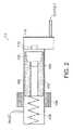
- FIG. 2shows a piston pump according to an embodiment of the invention
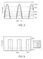
- FIG. 3shows an alternating current waveform suitable for driving the piston pump of FIG. 2 ;
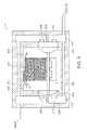
- FIG. 4shows a pulse-width-modulated direct current waveform suitable for driving the piston pump of FIG. 2 , according to an embodiment of the present invention
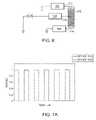
- FIG. 5is schematic diagram of a diaphragm pump according to an embodiment of the present invention.
- FIG. 6is a schematic diagram of a center-tapped coil for a diaphragm pump according to an embodiment of the present invention.
- FIGS. 7A-Bshows pulse-width-modulated direct current waveforms suitable for driving the center-tapped coil of FIG. 6 , according to embodiments of the present invention.
- FIGS. 8A-8Dshow embodiments of the invention that include a filter between fuel pump and combustion chamber.
- the fuel flow to a pressurized combustion chambermay be metered by varying the operating parameters of a fuel pump. Desired performance may be achieved without the throttle plates or valves or other restrictive devices that are normally used to meter the fuel flow to the combustion chamber.
- FIG. 1shows a metering pump system providing gaseous fuel to a pressurized combustion chamber 58 of an engine 22 according to an embodiment of the invention.
- a gas trainlabeled generally as 5 , includes a fuel pump 14 , interconnecting lines 38 , 42 and may include a pressure regulator 18 .
- the fuel pump 14raises the fuel pressure in line 38 to a higher pressure in line 42 .
- the gas traindelivers fuel from the gas supply to the burner 10 , where it is mixed with air and burned in a combustion chamber 58 .
- the fuel pumpis controlled by a controller 34 that modulates the fuel flow rate by varying one or more parameters of an electrical signal sent to the fuel pump 14 .
- the controllermay also regulate a blower 60 that provides air to the combustion chamber 58 and may receive signals from sensors that report engine-operating parameters.
- the delivered fuel pressure in line 38is 6 to 13 inches water column for liquefied petroleum gas. Natural gas may be supplied in line 38 at even lower pressures of 3 to 8 inches water column. Alternatively, pressure regulator 18 can supply the fuel at lower pressures, even negative pressures. Typical fuel pressures in line 42 may range from 0.5 to 5 PSIG.
- fuel pump 14is a linear piston pump.
- a linear piston pumpis shown in FIG. 2 .
- the pumpincludes a cylinder 100 , a piston 102 , a winding 104 , a spring 106 and check valves 108 , 112 .
- the windingpulls the ferrous metal piston 102 to the left, compressing the spring 106 .
- Check valve 108 in the pistonallows fuel to flow into compression volume 110 .
- the electrical signalis turned off and the electromagnetic force on the piston begins to decrease, the piston 102 is forced to the right by the spring 106 . Gas is forced out check valve 112 into the receiver volume 114 at a higher pressure.
- the flow rate of the pumpcan be modulated by varying the stroke of the piston 102 .
- the signal from the controller to the pumpis a half-wave alternating current (“AC”) signal, as shown in FIG. 3 . Circuitry to produce this signal is well known in the art.
- the piston stroke and, thus, the flow rateincreases as the amplitude of the AC signal increases.
- low amplitude signalsare biased slightly higher to improve repeatability and linearity of flow versus the driving signal.
- the force applied to the piston 102 by the windings 104is inversely proportional to the distance from the windings to the piston.
- a bias voltageis applied to bring the resting-position of the piston closer to the windings, so that small changes in the controller signal that drives the piston dominate the frictional forces and the inertia of the piston.
- the bias voltage added to the signalis highest at the lowest driving signal (10% signal in FIG. 3 ) and may drop to zero before the drive signal reaches 50%. The bias is reduced at higher flow levels to take advantage of the full pump stroke.
- the controller signal that drives the pumpis a pulse-width-modulated (“PWM”) direct current (“DC”) voltage signal.
- PWMpulse-width-modulated
- DCdirect current
- FIG. 4shows an exemplary DC waveform that may be used to drive the pump. Circuitry to generate the PWM DC signal in FIG. 4 is well known in the art. Three different drive signals are plotted versus time. These signal modulations correspond to 10%, 50% and 90% duty cycles, which are shown for purposes of illustration and not for limitation. Applying the rectangular wave voltages of FIG. 4 to the windings 104 of FIG. 2 will cause the piston 102 to move to the left and compress the spring 106 . The stroke and, therefore, the flow will be roughly proportional to the voltage times the duration of the signal.
- the lower signals, 10% and 50%include bias voltages between signal pulses.
- the bias voltagemoves the piston closer to the windings to provide greater piston response to small changes in the signal and overcome the frictional and inertia forces of the piston.
- This bias voltagemay be varied with the duration of the drive signal.
- the bias voltageis highest at the minimum drive signal duration and may drop to zero before the drive voltage pulse duty cycle reaches 50%.
- controller signal waveformsmay be used to drive the piston. Use of all such controller waveforms is within the scope of the present invention as defined in the appended claims.
- the piston pump of FIG. 2can be driven without the bias voltages shown in FIGS. 3 and 4 .
- both the frequency and the duration of the PWM DC controller signal modulating the pumpcan be varied to linearize the flow through the pump with changes in the driving signal.
- pump 14is a diaphragm pump as shown in FIG. 5 .
- one or more solenoidal coils 200drive the shaft of the pump 202 back and forth.
- the shaft 202deflects two diaphragms 204 that alternatively pull gas into the chambers 212 and then expel it.
- the two wire coilis driven with an AC signal connected to wires ( 234 , 236 ) that drives the piston 202 back and forth by reversing the flow of current through the coil 200 .
- the solenoidhas a permanent magnet so that a reversing magnetic field can drive the solenoid in opposite directions.
- the pumping force on the two chambers 212is phased 180 degrees apart so that as one chamber is filled, the companion chamber is emptied.
- Check valves 208 upstream of the pumping chamber 212allow gas flow in, while the downstream valves 210 allow flow out of the chambers and into the receiver volume 216 .
- the solenoidal coil 200can be driven with a full wave AC signal. In similar fashion to the piston pump, varying the amplitude of the AC signal will vary the stroke and, therefore, the fuel flow through the diaphragm pump.
- the electrical coil 200 in the diaphragm pump 14 of FIG. 5can be center-taped by adding a third wire 232 to the center of the coil 200 .
- Wires ( 234 & 236 )connect to each end of the coil. This three wire connection allows the piston 202 to be driven back and forth with a DC source.
- the DC sourceconnects to the center wire 232 and the other connecting wires ( 234 & 236 ) are alternatively connected to ground or a negative voltage, causing current to flow in one half-coil or the other.
- a three-wire coil 302 and devices ( 304 , 306 , 308 ) to control the DC current flow to the coilare shown schematically in FIG. 6 .
- the coilmay be used to drive a diaphragm pump solenoid, as in FIG. 5 .
- Devices ( 304 , 306 , 308 )may be relays, field effect transistors (“FET”), bipolar transistors or other similar devices.
- the controllercan vary the flow of fuel through the diaphragm pump by varying the amplitude of applied DC voltage signal 312 using device 304 .
- Devices 306 , 308can be driven as shown in FIG. 7A , where first one device is closed, then opened and then the other device is closed and then opened.
- the vertical axis of the figurecorresponds to a normalized driving voltage, where a signal equal to “1” means a device is closed (i.e., shorted).
- Control strategies using PWM signalsas illustrated in FIG. 4 , albeit without the bias described previously for the piston pump and with suitable phasing, can be applied to each of devices 306 , 308 in FIG. 6 .
- the amplitude and frequency of the diaphragm pump stroke of FIG. 5can be controlled using the three devices ( 302 , 304 , 306 ) shown in FIG. 6 .
- the amplitude of the pump strokeis controlled by the average voltage at wire 312 .
- This voltagecan be modulated by fast pulse-width-modulating device 304 .
- the stroke frequencymay be controlled as before by devices 306 and 308 .
- device 304can be eliminated and switches 306 and 308 can be pulse-width modulated at a high frequency during their “on” state, as illustrated in FIG. 7B .
- the center-tapped coilcan be replaced by a full bridge or a half-bridge, as known to those skilled in the art.
- a filter 801may be added between pump 800 and burner head 806 , where the fuel is mixed with the combustion air, as shown in FIG. 8A .
- One embodiment of the filter 801is an RC filter comprising a capacitance (volume) 802 and an orifice 804 .
- the volume and orificeare sized to allow the required fuel flow and reduce fluctuations in flow to a desired level. Mathematical techniques that are well known in the art may be used to determine these filter parameters.
- An acoustic filter using a volume and an orifice restrictorhas the electrical circuit analog shown in FIG. 8B .
- the analog of gas flowis electrical current
- the analog of gas pressureis electrical voltage
- the analog of volumeis electrical capacitance
- the analog of flow resistanceis electrical resistance
- the analog of gas inertiais electrical inductance.
- the orifice restrictordoes not translate directly into this model because the orifice flow resistance is proportional to the gas flow squared (non-linear) instead of being proportional to the gas flow as the model suggests.
- the modelcan be used through the process of linearization of flow resistance for small signals.
- the pump gas flow rippleis attenuated by the factor of 1/(1+2 ⁇ fRC).
- fis the frequency component of the gas flow entering the filter from the pump. Due to the orifice restrictor non-linear characteristics, the acoustic filter has a lower attenuation at low flow causing a high burner flow ripple as a percentage of average flow. The higher ripple can cause flame instability and higher emissions of pollutants. This non-linearity also causes a high resistance to average gas flow at the higher flow rates reducing the pump maximum flow capability.
- FIG. 8CThe addition of a long thin tube to the acoustic filter provides ripple attenuation through the gas mass acceleration, as shown in FIG. 8C .
- FIG. 8DThe diagram for the electrical analog is shown in FIG. 8D .
- the pump gas flow rippleis attenuated by the factor of 1/[1+(LC)(2 ⁇ f) 2 ]. Since L and C are not a function of flow, the filter attenuation is not affected by the flow rate and does not have the disadvantages of the filter of FIG. 8A . Attenuation of the ripple also increases the pump's flow rate.
- controller 34modulates the output of fuel pump 14 to control the temperature of the heater tubes 26 of the engine.
- the temperature of the heater tube 26may be measured with a temperature sensor 54 , such as a thermocouple, that is attached to a heater tube 26 .
- a temperature sensor 54such as a thermocouple
- the enginedraws more thermal energy from the heater tubes 26 .
- the tubescool and the thermocouple 54 reports this temperature drop to the controller 34 , which in turn increases the fuel flow until the measured temperature is restored to a specified level.
- Any of the devices and methods for metering the fuel through the fuel pump, as described above,may be employed in this embodiment of the invention.
- various fuel pump typesincluding rotary vane pumps, piezoelectric pumps, crank driven piston pumps, etc.
- various operating parameters of a systemmay be controlled by controlling the fuel pump to meter the fuel flow to the chamber.
- the speed of an internal combustion engine or the power output of an enginemay be determined by the controller.
- a fuel/air mixture ratio to a burnermay be maintained by the controller.
Landscapes
- Engineering & Computer Science (AREA)
- Chemical & Material Sciences (AREA)
- Combustion & Propulsion (AREA)
- Mechanical Engineering (AREA)
- General Engineering & Computer Science (AREA)
- General Chemical & Material Sciences (AREA)
- Chemical Kinetics & Catalysis (AREA)
- Oil, Petroleum & Natural Gas (AREA)
- Physics & Mathematics (AREA)
- General Physics & Mathematics (AREA)
- Automation & Control Theory (AREA)
- Reciprocating Pumps (AREA)
- Feeding And Controlling Fuel (AREA)
- Output Control And Ontrol Of Special Type Engine (AREA)
Abstract
Description
Claims (20)
Priority Applications (2)
| Application Number | Priority Date | Filing Date | Title |
|---|---|---|---|
| US11/534,979US7654084B2 (en) | 2000-03-02 | 2006-09-25 | Metering fuel pump |
| US12/698,438US20100269789A1 (en) | 2000-03-02 | 2010-02-02 | Metering fuel pump |
Applications Claiming Priority (6)
| Application Number | Priority Date | Filing Date | Title |
|---|---|---|---|
| US09/517,686US6247310B1 (en) | 1997-07-15 | 2000-03-02 | System and method for control of fuel and air delivery in a burner of a thermal-cycle engine |
| US09/853,239US6705081B2 (en) | 1997-07-15 | 2001-05-11 | System and method for sensor control of the fuel-air ratio in a burner |
| US09/883,077US6543215B2 (en) | 2001-06-15 | 2001-06-15 | Thermal improvements for an external combustion engine |
| US10/361,354US6857260B2 (en) | 2001-06-15 | 2003-02-10 | Thermal improvements for an external combustion engine |
| US10/643,147US7111460B2 (en) | 2000-03-02 | 2003-08-18 | Metering fuel pump |
| US11/534,979US7654084B2 (en) | 2000-03-02 | 2006-09-25 | Metering fuel pump |
Related Parent Applications (2)
| Application Number | Title | Priority Date | Filing Date |
|---|---|---|---|
| US10/361,354Continuation-In-PartUS6857260B2 (en) | 2000-03-02 | 2003-02-10 | Thermal improvements for an external combustion engine |
| US10/643,147ContinuationUS7111460B2 (en) | 2000-03-02 | 2003-08-18 | Metering fuel pump |
Related Child Applications (1)
| Application Number | Title | Priority Date | Filing Date |
|---|---|---|---|
| US12/698,438ContinuationUS20100269789A1 (en) | 2000-03-02 | 2010-02-02 | Metering fuel pump |
Publications (2)
| Publication Number | Publication Date |
|---|---|
| US20070028612A1 US20070028612A1 (en) | 2007-02-08 |
| US7654084B2true US7654084B2 (en) | 2010-02-02 |
Family
ID=34216372
Family Applications (3)
| Application Number | Title | Priority Date | Filing Date |
|---|---|---|---|
| US10/643,147Expired - LifetimeUS7111460B2 (en) | 2000-03-02 | 2003-08-18 | Metering fuel pump |
| US11/534,979Expired - Fee RelatedUS7654084B2 (en) | 2000-03-02 | 2006-09-25 | Metering fuel pump |
| US12/698,438AbandonedUS20100269789A1 (en) | 2000-03-02 | 2010-02-02 | Metering fuel pump |
Family Applications Before (1)
| Application Number | Title | Priority Date | Filing Date |
|---|---|---|---|
| US10/643,147Expired - LifetimeUS7111460B2 (en) | 2000-03-02 | 2003-08-18 | Metering fuel pump |
Family Applications After (1)
| Application Number | Title | Priority Date | Filing Date |
|---|---|---|---|
| US12/698,438AbandonedUS20100269789A1 (en) | 2000-03-02 | 2010-02-02 | Metering fuel pump |
Country Status (4)
| Country | Link |
|---|---|
| US (3) | US7111460B2 (en) |
| EP (1) | EP1660960B1 (en) |
| CA (1) | CA2537925C (en) |
| WO (1) | WO2005019633A2 (en) |
Cited By (4)
| Publication number | Priority date | Publication date | Assignee | Title |
|---|---|---|---|---|
| US20100269789A1 (en)* | 2000-03-02 | 2010-10-28 | New Power Concepts Llc | Metering fuel pump |
| US9335050B2 (en) | 2012-09-26 | 2016-05-10 | United Technologies Corporation | Gas turbine engine combustor |
| US9404654B2 (en) | 2012-09-26 | 2016-08-02 | United Technologies Corporation | Gas turbine engine combustor with integrated combustor vane |
| US9482432B2 (en) | 2012-09-26 | 2016-11-01 | United Technologies Corporation | Gas turbine engine combustor with integrated combustor vane having swirler |
Families Citing this family (33)
| Publication number | Priority date | Publication date | Assignee | Title |
|---|---|---|---|---|
| US8511105B2 (en) | 2002-11-13 | 2013-08-20 | Deka Products Limited Partnership | Water vending apparatus |
| US8069676B2 (en) | 2002-11-13 | 2011-12-06 | Deka Products Limited Partnership | Water vapor distillation apparatus, method and system |
| US7340879B2 (en) | 2002-11-13 | 2008-03-11 | Deka Products Limited Partnership | Locally powered water distillation system |
| ES2611010T3 (en)* | 2004-03-02 | 2017-05-04 | Riello S.P.A. | Electronic regulation device and electric motor applied to a burner fan |
| KR100610074B1 (en)* | 2004-04-29 | 2006-08-08 | 현대자동차주식회사 | Elpia Fuel Pump Diagnostic System |
| US7536274B2 (en)* | 2004-05-28 | 2009-05-19 | Fisher-Rosemount Systems, Inc. | System and method for detecting an abnormal situation associated with a heater |
| JP4830643B2 (en)* | 2005-09-01 | 2011-12-07 | コニカミノルタホールディングス株式会社 | Fluid transportation system |
| US11826681B2 (en) | 2006-06-30 | 2023-11-28 | Deka Products Limited Partneship | Water vapor distillation apparatus, method and system |
| US20080134676A1 (en)* | 2006-11-09 | 2008-06-12 | Che-Ning Chang | Power structure for a power-saving engine |
| CA2894441C (en) | 2007-04-23 | 2017-12-12 | New Power Concepts Llc | Stirling cycle machine |
| US8763391B2 (en) | 2007-04-23 | 2014-07-01 | Deka Products Limited Partnership | Stirling cycle machine |
| US11884555B2 (en) | 2007-06-07 | 2024-01-30 | Deka Products Limited Partnership | Water vapor distillation apparatus, method and system |
| US8505323B2 (en) | 2007-06-07 | 2013-08-13 | Deka Products Limited Partnership | Water vapor distillation apparatus, method and system |
| MX2009013337A (en) | 2007-06-07 | 2010-01-18 | Deka Products Lp | Water vapor distillation apparatus, method and system. |
| JP5115372B2 (en)* | 2008-07-11 | 2013-01-09 | トヨタ自動車株式会社 | Operation control device for gas turbine |
| MX354085B (en) | 2008-08-15 | 2018-02-09 | Deka Products Lp | Water vending apparatus with distillation unit. |
| US9822730B2 (en) | 2009-07-01 | 2017-11-21 | New Power Concepts, Llc | Floating rod seal for a stirling cycle machine |
| US9797341B2 (en) | 2009-07-01 | 2017-10-24 | New Power Concepts Llc | Linear cross-head bearing for stirling engine |
| EP2449244B1 (en) | 2009-07-01 | 2016-05-04 | New Power Concepts LLC | Stirling cycle machine |
| US9828940B2 (en) | 2009-07-01 | 2017-11-28 | New Power Concepts Llc | Stirling cycle machine |
| CN102330628B (en)* | 2010-07-13 | 2013-06-12 | 北汽福田汽车股份有限公司 | Method and equipment for detecting oil spraying rule of electric control mono-block pump |
| NZ587125A (en)* | 2010-07-30 | 2012-12-21 | Whisper Tech Ltd | System to adjust the themal output of a heat engine driving a generator without changing the electrical output |
| US20140034475A1 (en) | 2012-04-06 | 2014-02-06 | Deka Products Limited Partnership | Water Vapor Distillation Apparatus, Method and System |
| WO2014018896A1 (en) | 2012-07-27 | 2014-01-30 | Deka Products Limited Partnership | Control of conductivity in product water outlet for evaporation apparatus |
| CN105102803B (en)* | 2012-11-30 | 2018-04-27 | 冷王公司 | System and method for adjusting the pressure in fuel delivery system |
| WO2015023515A1 (en)* | 2013-08-13 | 2015-02-19 | Smith & Nephew, Inc. | Systems and methods for applying reduced pressure therapy |
| US9753443B2 (en) | 2014-04-21 | 2017-09-05 | Synerject Llc | Solenoid systems and methods for detecting length of travel |
| US9997287B2 (en) | 2014-06-06 | 2018-06-12 | Synerject Llc | Electromagnetic solenoids having controlled reluctance |
| WO2015191348A1 (en) | 2014-06-09 | 2015-12-17 | Synerject Llc | Methods and apparatus for cooling a solenoid coil of a solenoid pump |
| CN106523183B (en)* | 2017-01-03 | 2018-09-18 | 宁波华斯特林电机制造有限公司 | A kind of air-cooled Stirling cooling devcie of motor |
| US11598284B2 (en)* | 2018-12-20 | 2023-03-07 | Swedish Stirling Ab | Recovery of energy in residue gases |
| CN111947296B (en)* | 2020-07-21 | 2022-04-05 | 华帝股份有限公司 | Control method of full-premix gas water heater |
| JP7597438B2 (en)* | 2020-12-25 | 2024-12-10 | ミネベアミツミ株式会社 | PUMP SYSTEM, FLUID SUPPLY DEVICE, AND DRIVE CONTROL METHOD FOR PUMP SYSTEM - Patent application |
Citations (148)
| Publication number | Priority date | Publication date | Assignee | Title |
|---|---|---|---|---|
| US55516A (en) | 1866-06-12 | Improvement in steam-engines | ||
| US120222A (en) | 1871-10-24 | Improvement in pitmen-connections for steam-engines | ||
| US124805A (en) | 1872-03-19 | Improvement in apparatus for converting reciprocating into rotary motion | ||
| US321313A (en) | 1885-06-30 | Steam-engine | ||
| US488373A (en) | 1892-12-20 | John edward touch | ||
| US646406A (en) | 1899-05-17 | 1900-04-03 | Charles A Anderson | Hot-air fan-motor. |
| US1089651A (en) | 1913-10-23 | 1914-03-10 | Gregory Kovalavich | Motion-converter. |
| DE445033C (en) | 1922-12-12 | 1927-05-28 | Heinrich Schieferstein | Power transmission device for double-acting piston engines |
| US1769375A (en) | 1923-12-17 | 1930-07-01 | John C Leary | Piston-guiding means |
| US1831574A (en) | 1930-05-26 | 1931-11-10 | Ernest C Norton | Piston ring |
| US1840389A (en) | 1930-02-18 | 1932-01-12 | Charles E Eubank | Mechanical movement |
| US1866702A (en) | 1930-04-15 | 1932-07-12 | Cooper Bessemer Corp | Driving connection |
| GB395374A (en) | 1931-12-12 | 1933-07-12 | Paul Kleinewefers | Improvements in tubular heat exchange apparatus more particularly for heating air by flue gases |
| US2170099A (en) | 1936-12-15 | 1939-08-22 | Tilling Stevens Ltd | Engine having diametrically opposed cylinders |
| US2176657A (en) | 1937-02-17 | 1939-10-17 | Rca Corp | Air cooling for thermionic tubes |
| US2289984A (en) | 1940-07-12 | 1942-07-14 | Westinghouse Electric & Mfg Co | Air cooler for power tubes |
| US2337294A (en) | 1942-02-18 | 1943-12-21 | Taylor Winfield Corp | Fabrication method |
| US2419234A (en) | 1944-03-11 | 1947-04-22 | Scovill Manufacturing Co | Cooling unit |
| US2564100A (en) | 1947-08-07 | 1951-08-14 | Hartford Nat Bank & Trust Co | Hot gas apparatus including a regenerator |
| US2595457A (en) | 1947-06-03 | 1952-05-06 | Air Preheater | Pin fin heat exchanger |
| GB675161A (en) | 1945-08-07 | 1952-07-09 | Philips Nv | Improvements in or relating to hot-gas reciprocating engines |
| GB689484A (en) | 1949-08-17 | 1953-03-25 | Philips Nv | Improvements in or relating to heat exchangers |
| GB704002A (en) | 1950-02-10 | 1954-02-17 | Philips Nv | Improvements in hot-gas reciprocating engines |
| FR1063612A (en) | 1951-09-26 | 1954-05-05 | Philips Nv | Burner with a sheath surrounding the combustion chamber |
| US2688228A (en) | 1947-06-06 | 1954-09-07 | Hartford Nat Bank & Trust Co | Heat exchanger for hot gas engines |
| GB892962A (en) | 1957-12-05 | 1962-04-04 | Philips Nv | Improvements in or relating to heat exchangers |
| US3059418A (en) | 1961-03-07 | 1962-10-23 | Gen Motors Corp | Hydrostatic bearing means for an engine drive mechanism |
| US3293480A (en) | 1963-05-24 | 1966-12-20 | Varian Associates | Pole piece and collector assembly for high frequency electron discharge device with cooling ribs |
| US3431788A (en) | 1967-03-01 | 1969-03-11 | Philips Corp | Piston rod guide for rhombic drive stirling cycle apparatus |
| FR2067119A1 (en) | 1969-11-07 | 1971-08-20 | Guillon Marcel | |
| US3651641A (en)* | 1969-03-18 | 1972-03-28 | Ginter Corp | Engine system and thermogenerator therefor |
| US3742578A (en) | 1968-08-15 | 1973-07-03 | Philips Corp | Method of manufacturing a regenerator |
| US3775973A (en) | 1970-05-04 | 1973-12-04 | P Hudson | Combustion products pressure generators intermittent burner cycle and engines |
| US3782457A (en) | 1971-10-26 | 1974-01-01 | Rohr Corp | Recuperator and method of making |
| US3782120A (en)* | 1971-03-04 | 1974-01-01 | Philips Corp | Thermodynamic reciprocating machine with temperature-controlled fuel supply to burner |
| US3860384A (en) | 1972-05-25 | 1975-01-14 | Intelcon Rad Tech | Method to control NOX formation in fossil-fueled boiler furnaces |
| US3861223A (en) | 1973-04-30 | 1975-01-21 | Anton Braun | Fixed stroke piston machines with improved counterbalancing and driving mechanism |
| US3924477A (en) | 1974-07-01 | 1975-12-09 | William Portelance | Crank movement mechanism |
| US3940933A (en) | 1973-10-19 | 1976-03-02 | Forenade Fabriksverken | Method for regulating the output of a stirling-type hot gas engine and device for the same |
| US3956892A (en) | 1973-11-09 | 1976-05-18 | Forenade Fabriksverken | Fuel-air regulating system for hot gas engines |
| US4008039A (en) | 1975-05-16 | 1977-02-15 | International Harvester Company | Low emission burners and control systems therefor |
| US4020635A (en) | 1974-05-20 | 1977-05-03 | Automotive Products Ltd. | Power plants |
| US4041592A (en) | 1976-02-24 | 1977-08-16 | Corning Glass Works | Manufacture of multiple flow path body |
| US4067191A (en) | 1975-10-10 | 1978-01-10 | Forenade Fabriksverken | System for supplying fuel and combustion air to an external combustion engine |
| US4085588A (en) | 1976-04-05 | 1978-04-25 | Ford Motor Company | Concentric crossflow recuperator for stirling engine |
| US4169692A (en) | 1974-12-13 | 1979-10-02 | General Electric Company | Variable area turbine nozzle and means for sealing same |
| US4172363A (en) | 1977-05-16 | 1979-10-30 | U.S. Philips Corporation | Hot-gas engine |
| US4191241A (en) | 1978-12-20 | 1980-03-04 | Wing Industries, Inc. | Energy exchange wheel and method of fabrication |
| US4231222A (en)* | 1978-09-18 | 1980-11-04 | Ford Motor Company | Air fuel control system for Stirling engine |
| US4305457A (en) | 1979-08-20 | 1981-12-15 | United Aircraft Products, Inc. | High density fin material |
| US4313080A (en) | 1978-05-22 | 1982-01-26 | Battery Development Corporation | Method of charge control for vehicle hybrid drive batteries |
| US4330260A (en) | 1979-01-31 | 1982-05-18 | Jorgensen Lars L S | Method and apparatus for regulating the combustion in a furnace |
| US4330992A (en) | 1980-04-11 | 1982-05-25 | Sunpower, Inc. | Drive mechanism for Stirling engine displacer and other reciprocating bodies |
| US4343350A (en) | 1978-08-04 | 1982-08-10 | Uop Inc. | Double wall tubing assembly and method of making same |
| US4364724A (en) | 1978-06-02 | 1982-12-21 | Forenade Farbiksverken | Method and apparatus for dosing an air-fuel mixture in burners having evaporating tubes |
| US4384457A (en) | 1980-10-30 | 1983-05-24 | Harvey Roger O | Hot gas engine convertor |
| US4387568A (en) | 1980-07-14 | 1983-06-14 | Mechanical Technology Incorporated | Stirling engine displacer gas bearing |
| US4413475A (en) | 1982-07-28 | 1983-11-08 | Moscrip William M | Thermodynamic working fluids for Stirling-cycle, reciprocating thermal machines |
| US4416114A (en) | 1981-07-31 | 1983-11-22 | Martini William R | Thermal regenerative machine |
| US4434617A (en) | 1982-07-27 | 1984-03-06 | Mechanical Technology Incorporated | Start-up and control method and apparatus for resonant free piston Stirling engine |
| US4442670A (en) | 1982-07-12 | 1984-04-17 | Jacob Goldman | Closed-cycle heat-engine |
| US4445570A (en) | 1982-02-25 | 1984-05-01 | Retallick William B | High pressure combustor having a catalytic air preheater |
| US4511805A (en) | 1981-07-21 | 1985-04-16 | Bertin & Cie | Convertor for thermal energy into electrical energy using Stirling motor and integral electrical generator |
| US4527394A (en) | 1984-01-17 | 1985-07-09 | Corey John A | Heater head for stirling engine |
| US4538677A (en) | 1982-04-06 | 1985-09-03 | Energiagazdalkodasi Intezet | Helicoidally finned tubes |
| US4573320A (en) | 1985-05-03 | 1986-03-04 | Mechanical Technology Incorporated | Combustion system |
| DE3500124A1 (en) | 1985-01-04 | 1986-07-10 | Bomin-Solar GmbH & Co KG, 7850 Lörrach | Decentral supply unit operated by external heat supply for the alternative and combined generation of electrical energy, heat and cold |
| US4633667A (en) | 1985-03-20 | 1987-01-06 | Aisin Seiki Kabushiki Kaisha | Burner for Stirling engines |
| US4638633A (en) | 1985-10-22 | 1987-01-27 | Otters John L | External combustion engines |
| US4662176A (en) | 1985-04-15 | 1987-05-05 | Mitsubishi Denki Kabushiki Kaisha | Heat exchanger for a Stirling engine |
| US4676202A (en) | 1986-05-05 | 1987-06-30 | Johnson Kenneth A | Engine cooling system |
| US4736586A (en) | 1985-08-30 | 1988-04-12 | Mitsubishi Denki Kabushiki Kaisha | Seal mechanism for a Stirling engine |
| FR2609154A1 (en) | 1986-12-29 | 1988-07-01 | Pramata | Device for regulating combustion, especially the oxygen content of the combustion flue gases (smoke), by means of a burner using blown air, method of implementation and burner equipped with such a device |
| US4768341A (en) | 1983-12-07 | 1988-09-06 | Aisin Seiki Kabushiki Kaisha | Temperature control system for stirling engine |
| DE3734009A1 (en) | 1987-10-08 | 1989-04-20 | Oschatz Gmbh | Heat exchanger tube |
| US4824149A (en) | 1987-03-20 | 1989-04-25 | Man Technologie Gmbh | Generator set |
| US4881372A (en) | 1988-02-29 | 1989-11-21 | Aisin Seiki Kabushiki Kaisha | Stirling engine |
| US4898041A (en) | 1987-05-04 | 1990-02-06 | Islas John J | Drive linkage for reciprocating engine |
| US4901790A (en) | 1989-05-22 | 1990-02-20 | Stirling Thermal Motors, Inc. | Self-heated diffuser assembly for a heat pipe |
| US4977742A (en) | 1989-04-21 | 1990-12-18 | Stirling Thermal Motors, Inc. | Stirling engine with integrated gas combustor |
| US4996841A (en) | 1989-08-02 | 1991-03-05 | Stirling Thermal Motors, Inc. | Stirling cycle heat pump for heating and/or cooling systems |
| US5003777A (en) | 1990-06-25 | 1991-04-02 | Sunpower, Inc. | Asymmetric gas spring |
| US5005349A (en) | 1988-09-29 | 1991-04-09 | Aisin Seiki Kabushiki Kaisha | Stirling engine |
| DE3934535A1 (en) | 1989-10-17 | 1991-04-18 | Johannes Dipl Ing Friedlin | Collection of energy from sun - involves parabolic mirror and tubular absorber through which liq. is circulated under pressure |
| US5065579A (en) | 1990-10-12 | 1991-11-19 | Gas Research Institute | Feedback air-fuel control system for Stirling engines |
| EP0458115A1 (en) | 1990-05-19 | 1991-11-27 | STIRLING MOTORS GmbH | Device for generating electrical and heating energy |
| DE4018943A1 (en) | 1990-06-13 | 1991-12-19 | Helmut Prof Dr Rer Nat Krauch | Piston engine for use in regenerative cycles - produces optimum time slope using rotating eccentric transmission |
| US5074114A (en) | 1990-05-14 | 1991-12-24 | Stirling Thermal Motors, Inc. | Congeneration system with a stirling engine |
| US5095701A (en) | 1990-03-31 | 1992-03-17 | Aisin Seiki Kabushiki Kaisha | Apparatus for controlling rotational speed of Stirling engine |
| DE4102306A1 (en) | 1991-01-26 | 1992-08-06 | Goetze Ag | OVAL PISTON RING |
| US5148066A (en) | 1991-08-19 | 1992-09-15 | Sunpower, Inc. | Linear generator or motor with integral magnetic spring |
| US5172784A (en) | 1991-04-19 | 1992-12-22 | Varela Jr Arthur A | Hybrid electric propulsion system |
| US5174117A (en) | 1990-09-28 | 1992-12-29 | Aisin Seiki Kabushiki Kaisha | Free piston Stirling engine |
| US5199722A (en) | 1990-08-10 | 1993-04-06 | Kabushiki Kaisha Riken | Seal assembly for stirling engine |
| US5203170A (en) | 1991-03-27 | 1993-04-20 | Aisin Seiki Kabushiki Kaisha | Stirling engine generating system |
| US5228293A (en) | 1992-07-06 | 1993-07-20 | Mechanical Technology Inc. | Low temperature solar-to-electric power conversion system |
| DE4205283A1 (en) | 1992-02-21 | 1993-08-26 | Bayerische Motoren Werke Ag | IC engine etc. with hypocycloidal crank drive - has connecting rod big end bearing with bore for eccentric with bearing clearances of different sizes |
| DE4219583A1 (en) | 1992-06-15 | 1993-12-16 | Eder Franz X | Heat transfer device for heat engine - has working cylinder made of internal and external ribbed tubes |
| US5293853A (en)* | 1992-03-13 | 1994-03-15 | Robert Bosch Gmbh | System for controlling an internal combustion engine |
| DE4308888A1 (en) | 1993-03-19 | 1994-09-22 | Karl Dr Philberth | Heating installation which additionally generates electrical energy |
| US5441401A (en) | 1991-09-13 | 1995-08-15 | Aisin Seiki Kabushiki Kaisha | Method of decreasing nitrogen oxides in combustion device which performs continuous combustion, and apparatus therefor |
| US5459812A (en) | 1990-09-17 | 1995-10-17 | Strix Limited | Immersion heaters including sheet metal heat conduction link |
| FR2721982A1 (en) | 1994-06-30 | 1996-01-05 | Lakhdar Chaker | Piston machines with inverse connecting rods for IC engines |
| US5494135A (en) | 1993-11-08 | 1996-02-27 | Brackett; Douglas C. | Lubrication system for a conjugate drive mechanism |
| DE29520864U1 (en) | 1995-02-18 | 1996-05-23 | Institut für Luft- und Kältetechnik Gemeinnützige Gesellschaft mbH, 01309 Dresden | regenerator |
| US5522214A (en) | 1993-07-30 | 1996-06-04 | Stirling Technology Company | Flexure bearing support, with particular application to stirling machines |
| EP0607154B1 (en) | 1992-07-09 | 1996-09-18 | Saarberg Hydraulik GmbH | Energy converter on the hot-air engine principle |
| US5590526A (en) | 1995-05-08 | 1997-01-07 | Lg Electronics Inc. | Burner for stirling engines |
| US5590626A (en) | 1991-08-27 | 1997-01-07 | Mazda Motor Corporation | Reciprocating engine of a spark ignition type |
| US5596262A (en) | 1993-10-29 | 1997-01-21 | Mercedes-Benz Ag | Process for monitoring the charge level of a battery, and for informing the user of the battery when the monitored charge level is no longer reliable |
| US5642618A (en) | 1996-07-09 | 1997-07-01 | Stirling Technology Company | Combination gas and flexure spring construction for free piston devices |
| US5675974A (en) | 1994-01-18 | 1997-10-14 | Robert Bosch Gmbh | Heat exchanger |
| US5697430A (en) | 1995-04-04 | 1997-12-16 | Wolverine Tube, Inc. | Heat transfer tubes and methods of fabrication thereof |
| US5701965A (en) | 1993-02-24 | 1997-12-30 | Deka Products Limited Partnership | Human transporter |
| US5735681A (en) | 1993-03-19 | 1998-04-07 | The Regents, University Of California | Ultralean low swirl burner |
| US5743091A (en) | 1996-05-01 | 1998-04-28 | Stirling Technology Company | Heater head and regenerator assemblies for thermal regenerative machines |
| US5755100A (en) | 1997-03-24 | 1998-05-26 | Stirling Marine Power Limited | Hermetically sealed stirling engine generator |
| US5761985A (en) | 1995-11-07 | 1998-06-09 | Festo Kg | Fluid power cylinder |
| DE19745167A1 (en) | 1996-10-14 | 1998-06-10 | Volkswagen Ag | Stirling machine operating method for vehicle esp electric vehicle |
| US5771694A (en) | 1996-01-26 | 1998-06-30 | Stirling Thermal Motors, Inc. | Crosshead system for stirling engine |
| US5786640A (en) | 1995-02-13 | 1998-07-28 | Nippon Soken, Inc. | Generator control system for a hybrid vehicle driven by an electric motor and an internal combustion engine |
| US5804947A (en) | 1994-12-22 | 1998-09-08 | Toyota Jidosha Kabushiki Kaisha | Generator controller used in hybrid electric vehicle |
| DE19820192A1 (en) | 1997-04-28 | 1998-11-26 | Vaillant Joh Gmbh & Co | Ignition procedure for gas-heated burner |
| US5864770A (en) | 1996-03-14 | 1999-01-26 | Ziph; Benjamin | Speed and power control of an engine by modulation of the load torque |
| US5875863A (en) | 1996-03-22 | 1999-03-02 | Hyrum T. Jarvis | Power system for extending the effective range of hybrid electric vehicles |
| US5878570A (en) | 1994-04-23 | 1999-03-09 | Reithofer; Klaus | Apparatus for operating and controlling a free-piston stirling engine |
| US5881800A (en) | 1998-04-03 | 1999-03-16 | Chung; Kuang-Hua | Heat sink fastener |
| US5920133A (en) | 1996-08-29 | 1999-07-06 | Stirling Technology Company | Flexure bearing support assemblies, with particular application to stirling machines |
| US5921764A (en) | 1997-07-18 | 1999-07-13 | Stirling Thermal Motors, Inc. | Heat engine combustor |
| US5929538A (en) | 1997-06-27 | 1999-07-27 | Abacus Controls Inc. | Multimode power processor |
| US5945808A (en) | 1997-04-16 | 1999-08-31 | Nissan Motor Co., Ltd. | Hybrid electric vehicle with battery management |
| US5952813A (en) | 1997-04-14 | 1999-09-14 | Honda Giken Kogyo Kabushiki Kaisha | Battery charging system and electric vehicle with battery charging system |
| US5954039A (en) | 1998-04-01 | 1999-09-21 | Ford Global Technologies, Inc. | Air/fuel ratio control system |
| US5971091A (en) | 1993-02-24 | 1999-10-26 | Deka Products Limited Partnership | Transportation vehicles and methods |
| US6050092A (en) | 1998-08-28 | 2000-04-18 | Stirling Technology Company | Stirling cycle generator control system and method for regulating displacement amplitude of moving members |
| US6062023A (en) | 1997-07-15 | 2000-05-16 | New Power Concepts Llc | Cantilevered crankshaft stirling cycle machine |
| US6094912A (en) | 1999-02-12 | 2000-08-01 | Stirling Technology Company | Apparatus and method for adaptively controlling moving members within a closed cycle thermal regenerative machine |
| US6161610A (en) | 1996-06-27 | 2000-12-19 | Azar; Kaveh | Heat sink with arc shaped fins |
| US6161381A (en) | 1996-03-29 | 2000-12-19 | Sipra Patententwicklungs- U. Beteilgungsgesellschaft Mbh | Stirling engine |
| WO2000079114A1 (en) | 1999-06-17 | 2000-12-28 | New Power Concepts Llc | Folded guide link stirling engine |
| US6247310B1 (en) | 1997-07-15 | 2001-06-19 | New Power Concepts Llc | System and method for control of fuel and air delivery in a burner of a thermal-cycle engine |
| WO2001065100A2 (en) | 2000-03-02 | 2001-09-07 | New Power Concepts Llc | Auxiliary power unit |
| US20010042373A1 (en) | 1997-11-15 | 2001-11-22 | Bliesner Wayne T. | Apparatus and method for throttling a heat engine |
| US6347453B1 (en) | 1998-05-22 | 2002-02-19 | Matthew P. Mitchell | Assembly method for concentric foil regenerators |
| US6380637B1 (en) | 1996-09-19 | 2002-04-30 | Ztek Corporation | Off-board station and an electricity exchanging system suitable for use with a mobile vehicle power system |
| US6381958B1 (en) | 1997-07-15 | 2002-05-07 | New Power Concepts Llc | Stirling engine thermal system improvements |
| US6543215B2 (en) | 2001-06-15 | 2003-04-08 | New Power Concepts Llc | Thermal improvements for an external combustion engine |
| US7111460B2 (en)* | 2000-03-02 | 2006-09-26 | New Power Concepts Llc | Metering fuel pump |
Family Cites Families (42)
| Publication number | Priority date | Publication date | Assignee | Title |
|---|---|---|---|---|
| US2862482A (en)* | 1949-09-07 | 1958-12-02 | Hart David Kennedy | Internal combustion engine |
| US3577735A (en)* | 1969-11-05 | 1971-05-04 | Bolkow Ges Mit Beschrankter | Liquid fuel rocket engine construction |
| GB1305674A (en)* | 1971-05-21 | 1973-02-07 | ||
| US3969899A (en)* | 1972-04-18 | 1976-07-20 | Sadaharu Nakazawa | Fuel burning apparatus and heat engine incorporating the same |
| US3942327A (en)* | 1972-05-05 | 1976-03-09 | Thermo Electron Corporation | Control system for external combustion engine |
| US3913314A (en)* | 1972-06-09 | 1975-10-21 | Westinghouse Electric Corp | System and method for operating a gas turbine electric power plant with bypass flow fueling operation to provide improved reliability and extended apparatus life |
| US3909188A (en)* | 1972-08-22 | 1975-09-30 | Wallace W Velie | Fuel burner for liquid and gaseous fuels |
| US4009695A (en)* | 1972-11-14 | 1977-03-01 | Ule Louis A | Programmed valve system for internal combustion engine |
| US4008573A (en)* | 1975-12-09 | 1977-02-22 | General Electric Company | Motive fluids for external combustion engines |
| US4212163A (en)* | 1978-06-16 | 1980-07-15 | Mikina Stanley J | Heat engine |
| JPS5724463A (en) | 1980-07-16 | 1982-02-09 | Taisan Kogyo Kk | Automatic air extractor for electromagnetic plunger pump |
| US4441573A (en)* | 1980-09-04 | 1984-04-10 | Advanced Energy Systems Inc. | Fuel-efficient energy storage automotive drive system |
| US4538573A (en)* | 1981-01-30 | 1985-09-03 | General Dynamics Corporation | Electronic engine control |
| US4520763A (en)* | 1981-09-25 | 1985-06-04 | Ergenics Inc. | Fuel injection system |
| US4553988A (en)* | 1982-11-22 | 1985-11-19 | Matsushita Electric Industrial Company, Limited | High-temperature furnace having selectively permeable membranes for oxygen enrichment |
| US4577604A (en)* | 1984-09-28 | 1986-03-25 | Nissan Motor Company, Limited | Control system for fuel pump for internal combustion engine |
| JPS61128024A (en) | 1984-11-26 | 1986-06-16 | Noritsu Co Ltd | Forced draft type burner |
| JPS61128014A (en) | 1984-11-28 | 1986-06-16 | Matsushita Electric Ind Co Ltd | Petroleum combustion device |
| FR2595761B1 (en)* | 1986-03-14 | 1988-05-13 | Semt | INJECTION DEVICE FOR AN INTERNAL COMBUSTION ENGINE, ALLOWING THE INJECTION OF TWO FUELS |
| JPH0221123A (en) | 1988-07-11 | 1990-01-24 | Matsushita Electric Ind Co Ltd | Control device for hot water supply equipment |
| JPH02256856A (en) | 1989-03-28 | 1990-10-17 | Mitsubishi Electric Corp | Heating device for external combustion engines |
| JPH039058A (en) | 1989-06-01 | 1991-01-16 | Aisin Seiki Co Ltd | Combustion control device for stirling engine |
| US5020315A (en)* | 1989-08-08 | 1991-06-04 | United Technologies Corporation | Multiple function fuel valve and system |
| US5092301A (en)* | 1990-02-13 | 1992-03-03 | Zenith Fuel Systems, Inc. | Digital fuel control system for small engines |
| DE4005735A1 (en)* | 1990-02-23 | 1991-08-29 | Bosch Gmbh Robert | METHOD AND DEVICE FOR REGULATING / CONTROLLING THE RUNNING TIME OF AN INTERNAL COMBUSTION ENGINE |
| JPH04347410A (en) | 1991-05-24 | 1992-12-02 | Matsushita Electric Ind Co Ltd | Ignition controller for burner |
| DE4221805A1 (en)* | 1992-07-03 | 1994-01-05 | Mak System Gmbh | Starting control for gas turbine engine - has electronic control for progressive start=up with intermediate speed and final operating speed |
| JPH0886411A (en)* | 1994-09-19 | 1996-04-02 | Nippon Soken Inc | Combustion type heater |
| CA2163288A1 (en)* | 1994-12-30 | 1996-07-01 | William L. Learman | Engine demand fuel delivery system |
| DE19515775C2 (en) | 1995-04-28 | 1998-08-06 | Ficht Gmbh | Method for controlling an excitation coil of an electromagnetically driven reciprocating pump |
| JPH0915197A (en) | 1995-06-26 | 1997-01-17 | Aisin Seiki Co Ltd | Air-fuel ratio controller for external combustion engine |
| US5715797A (en)* | 1995-06-28 | 1998-02-10 | Nippondenso Co., Ltd. | Fuel supply system for internal combustion engine and method of adjusting it |
| US6705081B2 (en)* | 1997-07-15 | 2004-03-16 | New Power Concepts Llc | System and method for sensor control of the fuel-air ratio in a burner |
| JPH11257154A (en) | 1998-03-10 | 1999-09-21 | Sanyo Electric Co Ltd | External combustion-type heat gas engine |
| US6036053A (en)* | 1998-07-09 | 2000-03-14 | Lancer Partnership, Ltd. | Method and apparatus for controlling a pump |
| JP3616988B2 (en)* | 1999-11-08 | 2005-02-02 | 日東工器株式会社 | Electromagnetic diaphragm pump |
| US6484490B1 (en)* | 2000-05-09 | 2002-11-26 | Ingersoll-Rand Energy Systems Corp. | Gas turbine system and method |
| WO2002012708A1 (en) | 2000-08-02 | 2002-02-14 | Mikuni Corporation | Electronically controlled fuel injector |
| JP4119116B2 (en)* | 2001-08-02 | 2008-07-16 | 株式会社ミクニ | Fuel injection method |
| US6708481B2 (en)* | 2002-03-19 | 2004-03-23 | New Power Concepts Llc | Fuel injector for a liquid fuel burner |
| JP3906747B2 (en)* | 2002-06-14 | 2007-04-18 | 株式会社日立製作所 | Fuel supply apparatus using low boiling point fuel and control method thereof |
| US7934926B2 (en)* | 2004-05-06 | 2011-05-03 | Deka Products Limited Partnership | Gaseous fuel burner |
- 2003
- 2003-08-18USUS10/643,147patent/US7111460B2/ennot_activeExpired - Lifetime
- 2004
- 2004-08-18WOPCT/US2004/026901patent/WO2005019633A2/enactiveApplication Filing
- 2004-08-18EPEP04781561.8Apatent/EP1660960B1/ennot_activeExpired - Lifetime
- 2004-08-18CACA2537925Apatent/CA2537925C/ennot_activeExpired - Fee Related
- 2006
- 2006-09-25USUS11/534,979patent/US7654084B2/ennot_activeExpired - Fee Related
- 2010
- 2010-02-02USUS12/698,438patent/US20100269789A1/ennot_activeAbandoned
Patent Citations (150)
| Publication number | Priority date | Publication date | Assignee | Title |
|---|---|---|---|---|
| US55516A (en) | 1866-06-12 | Improvement in steam-engines | ||
| US120222A (en) | 1871-10-24 | Improvement in pitmen-connections for steam-engines | ||
| US124805A (en) | 1872-03-19 | Improvement in apparatus for converting reciprocating into rotary motion | ||
| US321313A (en) | 1885-06-30 | Steam-engine | ||
| US488373A (en) | 1892-12-20 | John edward touch | ||
| US646406A (en) | 1899-05-17 | 1900-04-03 | Charles A Anderson | Hot-air fan-motor. |
| US1089651A (en) | 1913-10-23 | 1914-03-10 | Gregory Kovalavich | Motion-converter. |
| DE445033C (en) | 1922-12-12 | 1927-05-28 | Heinrich Schieferstein | Power transmission device for double-acting piston engines |
| US1769375A (en) | 1923-12-17 | 1930-07-01 | John C Leary | Piston-guiding means |
| US1840389A (en) | 1930-02-18 | 1932-01-12 | Charles E Eubank | Mechanical movement |
| US1866702A (en) | 1930-04-15 | 1932-07-12 | Cooper Bessemer Corp | Driving connection |
| US1831574A (en) | 1930-05-26 | 1931-11-10 | Ernest C Norton | Piston ring |
| GB395374A (en) | 1931-12-12 | 1933-07-12 | Paul Kleinewefers | Improvements in tubular heat exchange apparatus more particularly for heating air by flue gases |
| US2170099A (en) | 1936-12-15 | 1939-08-22 | Tilling Stevens Ltd | Engine having diametrically opposed cylinders |
| US2176657A (en) | 1937-02-17 | 1939-10-17 | Rca Corp | Air cooling for thermionic tubes |
| US2289984A (en) | 1940-07-12 | 1942-07-14 | Westinghouse Electric & Mfg Co | Air cooler for power tubes |
| US2337294A (en) | 1942-02-18 | 1943-12-21 | Taylor Winfield Corp | Fabrication method |
| US2419234A (en) | 1944-03-11 | 1947-04-22 | Scovill Manufacturing Co | Cooling unit |
| GB675161A (en) | 1945-08-07 | 1952-07-09 | Philips Nv | Improvements in or relating to hot-gas reciprocating engines |
| US2595457A (en) | 1947-06-03 | 1952-05-06 | Air Preheater | Pin fin heat exchanger |
| US2688228A (en) | 1947-06-06 | 1954-09-07 | Hartford Nat Bank & Trust Co | Heat exchanger for hot gas engines |
| US2564100A (en) | 1947-08-07 | 1951-08-14 | Hartford Nat Bank & Trust Co | Hot gas apparatus including a regenerator |
| GB689484A (en) | 1949-08-17 | 1953-03-25 | Philips Nv | Improvements in or relating to heat exchangers |
| GB704002A (en) | 1950-02-10 | 1954-02-17 | Philips Nv | Improvements in hot-gas reciprocating engines |
| FR1063612A (en) | 1951-09-26 | 1954-05-05 | Philips Nv | Burner with a sheath surrounding the combustion chamber |
| GB892962A (en) | 1957-12-05 | 1962-04-04 | Philips Nv | Improvements in or relating to heat exchangers |
| US3059418A (en) | 1961-03-07 | 1962-10-23 | Gen Motors Corp | Hydrostatic bearing means for an engine drive mechanism |
| US3293480A (en) | 1963-05-24 | 1966-12-20 | Varian Associates | Pole piece and collector assembly for high frequency electron discharge device with cooling ribs |
| US3431788A (en) | 1967-03-01 | 1969-03-11 | Philips Corp | Piston rod guide for rhombic drive stirling cycle apparatus |
| US3742578A (en) | 1968-08-15 | 1973-07-03 | Philips Corp | Method of manufacturing a regenerator |
| US3651641A (en)* | 1969-03-18 | 1972-03-28 | Ginter Corp | Engine system and thermogenerator therefor |
| FR2067119A1 (en) | 1969-11-07 | 1971-08-20 | Guillon Marcel | |
| US3775973A (en) | 1970-05-04 | 1973-12-04 | P Hudson | Combustion products pressure generators intermittent burner cycle and engines |
| US3782120A (en)* | 1971-03-04 | 1974-01-01 | Philips Corp | Thermodynamic reciprocating machine with temperature-controlled fuel supply to burner |
| US3782457A (en) | 1971-10-26 | 1974-01-01 | Rohr Corp | Recuperator and method of making |
| US3860384A (en) | 1972-05-25 | 1975-01-14 | Intelcon Rad Tech | Method to control NOX formation in fossil-fueled boiler furnaces |
| US3861223A (en) | 1973-04-30 | 1975-01-21 | Anton Braun | Fixed stroke piston machines with improved counterbalancing and driving mechanism |
| US3940933A (en) | 1973-10-19 | 1976-03-02 | Forenade Fabriksverken | Method for regulating the output of a stirling-type hot gas engine and device for the same |
| US3956892A (en) | 1973-11-09 | 1976-05-18 | Forenade Fabriksverken | Fuel-air regulating system for hot gas engines |
| US4020635A (en) | 1974-05-20 | 1977-05-03 | Automotive Products Ltd. | Power plants |
| US3924477A (en) | 1974-07-01 | 1975-12-09 | William Portelance | Crank movement mechanism |
| US4169692A (en) | 1974-12-13 | 1979-10-02 | General Electric Company | Variable area turbine nozzle and means for sealing same |
| US4008039A (en) | 1975-05-16 | 1977-02-15 | International Harvester Company | Low emission burners and control systems therefor |
| US4067191A (en) | 1975-10-10 | 1978-01-10 | Forenade Fabriksverken | System for supplying fuel and combustion air to an external combustion engine |
| US4041592A (en) | 1976-02-24 | 1977-08-16 | Corning Glass Works | Manufacture of multiple flow path body |
| US4085588A (en) | 1976-04-05 | 1978-04-25 | Ford Motor Company | Concentric crossflow recuperator for stirling engine |
| US4172363A (en) | 1977-05-16 | 1979-10-30 | U.S. Philips Corporation | Hot-gas engine |
| US4313080A (en) | 1978-05-22 | 1982-01-26 | Battery Development Corporation | Method of charge control for vehicle hybrid drive batteries |
| US4364724A (en) | 1978-06-02 | 1982-12-21 | Forenade Farbiksverken | Method and apparatus for dosing an air-fuel mixture in burners having evaporating tubes |
| US4343350A (en) | 1978-08-04 | 1982-08-10 | Uop Inc. | Double wall tubing assembly and method of making same |
| US4231222A (en)* | 1978-09-18 | 1980-11-04 | Ford Motor Company | Air fuel control system for Stirling engine |
| US4191241A (en) | 1978-12-20 | 1980-03-04 | Wing Industries, Inc. | Energy exchange wheel and method of fabrication |
| US4330260A (en) | 1979-01-31 | 1982-05-18 | Jorgensen Lars L S | Method and apparatus for regulating the combustion in a furnace |
| US4305457A (en) | 1979-08-20 | 1981-12-15 | United Aircraft Products, Inc. | High density fin material |
| US4330992A (en) | 1980-04-11 | 1982-05-25 | Sunpower, Inc. | Drive mechanism for Stirling engine displacer and other reciprocating bodies |
| US4387568A (en) | 1980-07-14 | 1983-06-14 | Mechanical Technology Incorporated | Stirling engine displacer gas bearing |
| US4384457A (en) | 1980-10-30 | 1983-05-24 | Harvey Roger O | Hot gas engine convertor |
| US4511805A (en) | 1981-07-21 | 1985-04-16 | Bertin & Cie | Convertor for thermal energy into electrical energy using Stirling motor and integral electrical generator |
| US4416114A (en) | 1981-07-31 | 1983-11-22 | Martini William R | Thermal regenerative machine |
| US4445570A (en) | 1982-02-25 | 1984-05-01 | Retallick William B | High pressure combustor having a catalytic air preheater |
| US4538677A (en) | 1982-04-06 | 1985-09-03 | Energiagazdalkodasi Intezet | Helicoidally finned tubes |
| US4442670A (en) | 1982-07-12 | 1984-04-17 | Jacob Goldman | Closed-cycle heat-engine |
| US4434617A (en) | 1982-07-27 | 1984-03-06 | Mechanical Technology Incorporated | Start-up and control method and apparatus for resonant free piston Stirling engine |
| US4413475A (en) | 1982-07-28 | 1983-11-08 | Moscrip William M | Thermodynamic working fluids for Stirling-cycle, reciprocating thermal machines |
| US4768341A (en) | 1983-12-07 | 1988-09-06 | Aisin Seiki Kabushiki Kaisha | Temperature control system for stirling engine |
| US4527394A (en) | 1984-01-17 | 1985-07-09 | Corey John A | Heater head for stirling engine |
| DE3500124A1 (en) | 1985-01-04 | 1986-07-10 | Bomin-Solar GmbH & Co KG, 7850 Lörrach | Decentral supply unit operated by external heat supply for the alternative and combined generation of electrical energy, heat and cold |
| US4633667A (en) | 1985-03-20 | 1987-01-06 | Aisin Seiki Kabushiki Kaisha | Burner for Stirling engines |
| US4662176A (en) | 1985-04-15 | 1987-05-05 | Mitsubishi Denki Kabushiki Kaisha | Heat exchanger for a Stirling engine |
| US4573320A (en) | 1985-05-03 | 1986-03-04 | Mechanical Technology Incorporated | Combustion system |
| US4736586A (en) | 1985-08-30 | 1988-04-12 | Mitsubishi Denki Kabushiki Kaisha | Seal mechanism for a Stirling engine |
| US4638633A (en) | 1985-10-22 | 1987-01-27 | Otters John L | External combustion engines |
| US4676202A (en) | 1986-05-05 | 1987-06-30 | Johnson Kenneth A | Engine cooling system |
| FR2609154A1 (en) | 1986-12-29 | 1988-07-01 | Pramata | Device for regulating combustion, especially the oxygen content of the combustion flue gases (smoke), by means of a burner using blown air, method of implementation and burner equipped with such a device |
| US4824149A (en) | 1987-03-20 | 1989-04-25 | Man Technologie Gmbh | Generator set |
| US4898041A (en) | 1987-05-04 | 1990-02-06 | Islas John J | Drive linkage for reciprocating engine |
| DE3734009A1 (en) | 1987-10-08 | 1989-04-20 | Oschatz Gmbh | Heat exchanger tube |
| US4881372A (en) | 1988-02-29 | 1989-11-21 | Aisin Seiki Kabushiki Kaisha | Stirling engine |
| US5005349A (en) | 1988-09-29 | 1991-04-09 | Aisin Seiki Kabushiki Kaisha | Stirling engine |
| US4977742A (en) | 1989-04-21 | 1990-12-18 | Stirling Thermal Motors, Inc. | Stirling engine with integrated gas combustor |
| US4901790A (en) | 1989-05-22 | 1990-02-20 | Stirling Thermal Motors, Inc. | Self-heated diffuser assembly for a heat pipe |
| US4996841A (en) | 1989-08-02 | 1991-03-05 | Stirling Thermal Motors, Inc. | Stirling cycle heat pump for heating and/or cooling systems |
| DE3934535A1 (en) | 1989-10-17 | 1991-04-18 | Johannes Dipl Ing Friedlin | Collection of energy from sun - involves parabolic mirror and tubular absorber through which liq. is circulated under pressure |
| US5095701A (en) | 1990-03-31 | 1992-03-17 | Aisin Seiki Kabushiki Kaisha | Apparatus for controlling rotational speed of Stirling engine |
| US5074114A (en) | 1990-05-14 | 1991-12-24 | Stirling Thermal Motors, Inc. | Congeneration system with a stirling engine |
| EP0458115A1 (en) | 1990-05-19 | 1991-11-27 | STIRLING MOTORS GmbH | Device for generating electrical and heating energy |
| DE4018943A1 (en) | 1990-06-13 | 1991-12-19 | Helmut Prof Dr Rer Nat Krauch | Piston engine for use in regenerative cycles - produces optimum time slope using rotating eccentric transmission |
| US5003777A (en) | 1990-06-25 | 1991-04-02 | Sunpower, Inc. | Asymmetric gas spring |
| US5199722A (en) | 1990-08-10 | 1993-04-06 | Kabushiki Kaisha Riken | Seal assembly for stirling engine |
| US5459812A (en) | 1990-09-17 | 1995-10-17 | Strix Limited | Immersion heaters including sheet metal heat conduction link |
| US5174117A (en) | 1990-09-28 | 1992-12-29 | Aisin Seiki Kabushiki Kaisha | Free piston Stirling engine |
| US5065579A (en) | 1990-10-12 | 1991-11-19 | Gas Research Institute | Feedback air-fuel control system for Stirling engines |
| DE4102306A1 (en) | 1991-01-26 | 1992-08-06 | Goetze Ag | OVAL PISTON RING |
| US5203170A (en) | 1991-03-27 | 1993-04-20 | Aisin Seiki Kabushiki Kaisha | Stirling engine generating system |
| US5172784A (en) | 1991-04-19 | 1992-12-22 | Varela Jr Arthur A | Hybrid electric propulsion system |
| US5148066A (en) | 1991-08-19 | 1992-09-15 | Sunpower, Inc. | Linear generator or motor with integral magnetic spring |
| US5590626A (en) | 1991-08-27 | 1997-01-07 | Mazda Motor Corporation | Reciprocating engine of a spark ignition type |
| US5441401A (en) | 1991-09-13 | 1995-08-15 | Aisin Seiki Kabushiki Kaisha | Method of decreasing nitrogen oxides in combustion device which performs continuous combustion, and apparatus therefor |
| DE4205283A1 (en) | 1992-02-21 | 1993-08-26 | Bayerische Motoren Werke Ag | IC engine etc. with hypocycloidal crank drive - has connecting rod big end bearing with bore for eccentric with bearing clearances of different sizes |
| US5293853A (en)* | 1992-03-13 | 1994-03-15 | Robert Bosch Gmbh | System for controlling an internal combustion engine |
| DE4219583A1 (en) | 1992-06-15 | 1993-12-16 | Eder Franz X | Heat transfer device for heat engine - has working cylinder made of internal and external ribbed tubes |
| US5228293A (en) | 1992-07-06 | 1993-07-20 | Mechanical Technology Inc. | Low temperature solar-to-electric power conversion system |
| EP0607154B1 (en) | 1992-07-09 | 1996-09-18 | Saarberg Hydraulik GmbH | Energy converter on the hot-air engine principle |
| US5971091A (en) | 1993-02-24 | 1999-10-26 | Deka Products Limited Partnership | Transportation vehicles and methods |
| US5701965A (en) | 1993-02-24 | 1997-12-30 | Deka Products Limited Partnership | Human transporter |
| US5735681A (en) | 1993-03-19 | 1998-04-07 | The Regents, University Of California | Ultralean low swirl burner |
| DE4308888A1 (en) | 1993-03-19 | 1994-09-22 | Karl Dr Philberth | Heating installation which additionally generates electrical energy |
| US5522214A (en) | 1993-07-30 | 1996-06-04 | Stirling Technology Company | Flexure bearing support, with particular application to stirling machines |
| US5596262A (en) | 1993-10-29 | 1997-01-21 | Mercedes-Benz Ag | Process for monitoring the charge level of a battery, and for informing the user of the battery when the monitored charge level is no longer reliable |
| US5494135A (en) | 1993-11-08 | 1996-02-27 | Brackett; Douglas C. | Lubrication system for a conjugate drive mechanism |
| US5675974A (en) | 1994-01-18 | 1997-10-14 | Robert Bosch Gmbh | Heat exchanger |
| US5878570A (en) | 1994-04-23 | 1999-03-09 | Reithofer; Klaus | Apparatus for operating and controlling a free-piston stirling engine |
| FR2721982A1 (en) | 1994-06-30 | 1996-01-05 | Lakhdar Chaker | Piston machines with inverse connecting rods for IC engines |
| US5804947A (en) | 1994-12-22 | 1998-09-08 | Toyota Jidosha Kabushiki Kaisha | Generator controller used in hybrid electric vehicle |
| US5786640A (en) | 1995-02-13 | 1998-07-28 | Nippon Soken, Inc. | Generator control system for a hybrid vehicle driven by an electric motor and an internal combustion engine |
| DE29520864U1 (en) | 1995-02-18 | 1996-05-23 | Institut für Luft- und Kältetechnik Gemeinnützige Gesellschaft mbH, 01309 Dresden | regenerator |
| US5697430A (en) | 1995-04-04 | 1997-12-16 | Wolverine Tube, Inc. | Heat transfer tubes and methods of fabrication thereof |
| US5590526A (en) | 1995-05-08 | 1997-01-07 | Lg Electronics Inc. | Burner for stirling engines |
| US5761985A (en) | 1995-11-07 | 1998-06-09 | Festo Kg | Fluid power cylinder |
| US5771694A (en) | 1996-01-26 | 1998-06-30 | Stirling Thermal Motors, Inc. | Crosshead system for stirling engine |
| EP0900328B1 (en) | 1996-03-14 | 2002-11-13 | STM Power, Inc. | Speed and power control of an engine by modulation of the load torque |
| US5864770A (en) | 1996-03-14 | 1999-01-26 | Ziph; Benjamin | Speed and power control of an engine by modulation of the load torque |
| US5875863A (en) | 1996-03-22 | 1999-03-02 | Hyrum T. Jarvis | Power system for extending the effective range of hybrid electric vehicles |
| US6161381A (en) | 1996-03-29 | 2000-12-19 | Sipra Patententwicklungs- U. Beteilgungsgesellschaft Mbh | Stirling engine |
| US5743091A (en) | 1996-05-01 | 1998-04-28 | Stirling Technology Company | Heater head and regenerator assemblies for thermal regenerative machines |
| US6161610A (en) | 1996-06-27 | 2000-12-19 | Azar; Kaveh | Heat sink with arc shaped fins |
| US5642618A (en) | 1996-07-09 | 1997-07-01 | Stirling Technology Company | Combination gas and flexure spring construction for free piston devices |
| US5920133A (en) | 1996-08-29 | 1999-07-06 | Stirling Technology Company | Flexure bearing support assemblies, with particular application to stirling machines |
| US6380637B1 (en) | 1996-09-19 | 2002-04-30 | Ztek Corporation | Off-board station and an electricity exchanging system suitable for use with a mobile vehicle power system |
| DE19745167A1 (en) | 1996-10-14 | 1998-06-10 | Volkswagen Ag | Stirling machine operating method for vehicle esp electric vehicle |
| US5755100A (en) | 1997-03-24 | 1998-05-26 | Stirling Marine Power Limited | Hermetically sealed stirling engine generator |
| US5952813A (en) | 1997-04-14 | 1999-09-14 | Honda Giken Kogyo Kabushiki Kaisha | Battery charging system and electric vehicle with battery charging system |
| US5945808A (en) | 1997-04-16 | 1999-08-31 | Nissan Motor Co., Ltd. | Hybrid electric vehicle with battery management |
| DE19820192A1 (en) | 1997-04-28 | 1998-11-26 | Vaillant Joh Gmbh & Co | Ignition procedure for gas-heated burner |
| US5929538A (en) | 1997-06-27 | 1999-07-27 | Abacus Controls Inc. | Multimode power processor |
| US6247310B1 (en) | 1997-07-15 | 2001-06-19 | New Power Concepts Llc | System and method for control of fuel and air delivery in a burner of a thermal-cycle engine |
| US6381958B1 (en) | 1997-07-15 | 2002-05-07 | New Power Concepts Llc | Stirling engine thermal system improvements |
| US6062023A (en) | 1997-07-15 | 2000-05-16 | New Power Concepts Llc | Cantilevered crankshaft stirling cycle machine |
| US5921764A (en) | 1997-07-18 | 1999-07-13 | Stirling Thermal Motors, Inc. | Heat engine combustor |
| US20010042373A1 (en) | 1997-11-15 | 2001-11-22 | Bliesner Wayne T. | Apparatus and method for throttling a heat engine |
| US5954039A (en) | 1998-04-01 | 1999-09-21 | Ford Global Technologies, Inc. | Air/fuel ratio control system |
| US5881800A (en) | 1998-04-03 | 1999-03-16 | Chung; Kuang-Hua | Heat sink fastener |
| US6347453B1 (en) | 1998-05-22 | 2002-02-19 | Matthew P. Mitchell | Assembly method for concentric foil regenerators |
| US6050092A (en) | 1998-08-28 | 2000-04-18 | Stirling Technology Company | Stirling cycle generator control system and method for regulating displacement amplitude of moving members |
| US6094912A (en) | 1999-02-12 | 2000-08-01 | Stirling Technology Company | Apparatus and method for adaptively controlling moving members within a closed cycle thermal regenerative machine |
| US6253550B1 (en) | 1999-06-17 | 2001-07-03 | New Power Concepts Llc | Folded guide link stirling engine |
| WO2000079114A1 (en) | 1999-06-17 | 2000-12-28 | New Power Concepts Llc | Folded guide link stirling engine |
| WO2001065100A2 (en) | 2000-03-02 | 2001-09-07 | New Power Concepts Llc | Auxiliary power unit |
| US7111460B2 (en)* | 2000-03-02 | 2006-09-26 | New Power Concepts Llc | Metering fuel pump |
| US6543215B2 (en) | 2001-06-15 | 2003-04-08 | New Power Concepts Llc | Thermal improvements for an external combustion engine |
Non-Patent Citations (10)
| Title |
|---|
| AAVID Thermal Technologies, Inc., Product Selection Guide, Jan. 1996, 4 pages. |
| Anderson, et al., The Effects of APU Characteristics on the Design of Hybrid Control Strategies for Hybrid Electric Vehicles, SAE Technical Paper Series, Feb. 27-Mar. 2, 1995, pp. 67-71. |
| Dickinson, et al., Performance, Management and Testing Requirement for Hybrid Electric Vehicle Batteries, SAE Technical Paper Series, Aug. 11-13, 1998, 11 pages. |
| Eder, F., Apparatus for Heat Transfer at Elevated Temperature, to the Working Medium of a Regenerative Thermal Engine (or "energy engine"), Jun. 15, 1992, 20 pages. |
| Fleming, et al, Rapid Recharge Capability of Valve Regulated Lead Acid Batteries for EV & HEV Applications, 9 pages. |
| Hargreaves, The Regenerator:, The Phillip's Stirling Engine, 1991, 9 pages. |
| Hobbs, R., Development of Optimized Fast Charge Algorithms for Lead Acid Batteries, SAE Technical Paper Series, Mar. 1-4, 1999, 9 pages. |
| Hochgraf, et al., Engine Control Strategy for a Series Hybrid Electric Vehicle Incorporating Load-Leveling and Computer Controlled Energy Management, SAE Technical Paper Series, Feb. 26-29, 1996, pp. 11-24. |
| Oman, H., New Energy Management Technology Gives Hybrid Cars Long Battery Life, SAE Technical Paper Series, Aug. 2-5, 1999, 8 pages. |
| Wiegman, H., Battery State Control Techniques for Charge Sustaining Applications, SAE Technical Paper Series, Feb. 23-26, 1998, pp. 65-75. |
Cited By (4)
| Publication number | Priority date | Publication date | Assignee | Title |
|---|---|---|---|---|
| US20100269789A1 (en)* | 2000-03-02 | 2010-10-28 | New Power Concepts Llc | Metering fuel pump |
| US9335050B2 (en) | 2012-09-26 | 2016-05-10 | United Technologies Corporation | Gas turbine engine combustor |
| US9404654B2 (en) | 2012-09-26 | 2016-08-02 | United Technologies Corporation | Gas turbine engine combustor with integrated combustor vane |
| US9482432B2 (en) | 2012-09-26 | 2016-11-01 | United Technologies Corporation | Gas turbine engine combustor with integrated combustor vane having swirler |
Also Published As
| Publication number | Publication date |
|---|---|
| WO2005019633A3 (en) | 2005-11-03 |
| US20040033140A1 (en) | 2004-02-19 |
| US20070028612A1 (en) | 2007-02-08 |
| US20100269789A1 (en) | 2010-10-28 |
| EP1660960B1 (en) | 2013-08-14 |
| CA2537925C (en) | 2011-03-29 |
| CA2537925A1 (en) | 2005-03-03 |
| US7111460B2 (en) | 2006-09-26 |
| EP1660960A2 (en) | 2006-05-31 |
| WO2005019633A2 (en) | 2005-03-03 |
Similar Documents
| Publication | Publication Date | Title |
|---|---|---|
| US7654084B2 (en) | Metering fuel pump | |
| US4366524A (en) | Electromechanical transducer controlling device | |
| KR100571224B1 (en) | Linear compressor driving device, medium and information assembly | |
| US6729601B2 (en) | Extended range proportional valve | |
| US6174136B1 (en) | Pump control and method of operating same | |
| EP0803026B1 (en) | Method and systems for injection valve controller | |
| JP3100163B2 (en) | Variable spring free piston Stirling machine | |
| JPS63143361A (en) | Controlling method for injector valve | |
| US20070286751A1 (en) | Capacity control of a compressor | |
| JP3851140B2 (en) | Driving method of electromagnetic proportional control valve for flow control | |
| WO1981002615A1 (en) | Gas-flow regulating system | |
| EP0785353A1 (en) | Temperature-compensated exhaust gas recirculation system | |
| CA1075987A (en) | Fuel injection system | |
| US20210164458A1 (en) | Pump drive that minimizes a pulse width based on voltage data to improve intake and discharge strokes | |
| JP3782252B2 (en) | Method and apparatus for controlling fuel pressure regulating valve | |
| US4022174A (en) | Electromagnetically actuated pumps | |
| JP2786332B2 (en) | Solenoid operation control method and device | |
| US6357422B1 (en) | Fuel pressure regulation system | |
| JPS63500050A (en) | Fluid flow electrical control device | |
| Cadman et al. | Electrodynamic oscillating compressors: Part 2—evaluation of specific designs for gas loads | |
| EP0065012A1 (en) | Electromagnetic actuator | |
| Ellison et al. | Design and testing of a bidirectional magnetostrictive-hydraulic hybrid actuator | |
| US4210116A (en) | Electromagnetically actuated pumps | |
| MXPA01010330A (en) | Communication system and method for efficiently implementing electronic transactions in mobile communication networks. | |
| US4343275A (en) | Electromagnetically actuated pumps |
Legal Events
| Date | Code | Title | Description |
|---|---|---|---|
| AS | Assignment | Owner name:NEW POWER CONCEPTS LLC,NEW HAMPSHIRE Free format text:ASSIGNMENT OF ASSIGNORS INTEREST;ASSIGNORS:JENSEN, ERIC R.;LANGENFELD, CHRISTOPHER;NEWELL, SCOTT W.;AND OTHERS;REEL/FRAME:018431/0572 Effective date:20030807 Owner name:NEW POWER CONCEPTS LLC, NEW HAMPSHIRE Free format text:ASSIGNMENT OF ASSIGNORS INTEREST;ASSIGNORS:JENSEN, ERIC R.;LANGENFELD, CHRISTOPHER;NEWELL, SCOTT W.;AND OTHERS;REEL/FRAME:018431/0572 Effective date:20030807 | |
| STCF | Information on status: patent grant | Free format text:PATENTED CASE | |
| FPAY | Fee payment | Year of fee payment:4 | |
| FPAY | Fee payment | Year of fee payment:8 | |
| FEPP | Fee payment procedure | Free format text:MAINTENANCE FEE REMINDER MAILED (ORIGINAL EVENT CODE: REM.); ENTITY STATUS OF PATENT OWNER: LARGE ENTITY | |
| LAPS | Lapse for failure to pay maintenance fees | Free format text:PATENT EXPIRED FOR FAILURE TO PAY MAINTENANCE FEES (ORIGINAL EVENT CODE: EXP.); ENTITY STATUS OF PATENT OWNER: LARGE ENTITY | |
| STCH | Information on status: patent discontinuation | Free format text:PATENT EXPIRED DUE TO NONPAYMENT OF MAINTENANCE FEES UNDER 37 CFR 1.362 | |
| FP | Lapsed due to failure to pay maintenance fee | Effective date:20220202 |