US7654079B2 - Diesel oxidation catalyst filter heating system - Google Patents
Diesel oxidation catalyst filter heating systemDownload PDFInfo
- Publication number
- US7654079B2 US7654079B2US11/593,722US59372206AUS7654079B2US 7654079 B2US7654079 B2US 7654079B2US 59372206 AUS59372206 AUS 59372206AUS 7654079 B2US7654079 B2US 7654079B2
- Authority
- US
- United States
- Prior art keywords
- engine
- value
- flow
- exhaust
- exhaust gas
- Prior art date
- Legal status (The legal status is an assumption and is not a legal conclusion. Google has not performed a legal analysis and makes no representation as to the accuracy of the status listed.)
- Active, expires
Links
Images


Classifications
- F—MECHANICAL ENGINEERING; LIGHTING; HEATING; WEAPONS; BLASTING
- F01—MACHINES OR ENGINES IN GENERAL; ENGINE PLANTS IN GENERAL; STEAM ENGINES
- F01N—GAS-FLOW SILENCERS OR EXHAUST APPARATUS FOR MACHINES OR ENGINES IN GENERAL; GAS-FLOW SILENCERS OR EXHAUST APPARATUS FOR INTERNAL-COMBUSTION ENGINES
- F01N3/00—Exhaust or silencing apparatus having means for purifying, rendering innocuous, or otherwise treating exhaust
- F01N3/02—Exhaust or silencing apparatus having means for purifying, rendering innocuous, or otherwise treating exhaust for cooling, or for removing solid constituents of, exhaust
- F01N3/021—Exhaust or silencing apparatus having means for purifying, rendering innocuous, or otherwise treating exhaust for cooling, or for removing solid constituents of, exhaust by means of filters
- F01N3/023—Exhaust or silencing apparatus having means for purifying, rendering innocuous, or otherwise treating exhaust for cooling, or for removing solid constituents of, exhaust by means of filters using means for regenerating the filters, e.g. by burning trapped particles
- F01N3/0231—Exhaust or silencing apparatus having means for purifying, rendering innocuous, or otherwise treating exhaust for cooling, or for removing solid constituents of, exhaust by means of filters using means for regenerating the filters, e.g. by burning trapped particles using special exhaust apparatus upstream of the filter for producing nitrogen dioxide, e.g. for continuous filter regeneration systems [CRT]
- F—MECHANICAL ENGINEERING; LIGHTING; HEATING; WEAPONS; BLASTING
- F01—MACHINES OR ENGINES IN GENERAL; ENGINE PLANTS IN GENERAL; STEAM ENGINES
- F01N—GAS-FLOW SILENCERS OR EXHAUST APPARATUS FOR MACHINES OR ENGINES IN GENERAL; GAS-FLOW SILENCERS OR EXHAUST APPARATUS FOR INTERNAL-COMBUSTION ENGINES
- F01N3/00—Exhaust or silencing apparatus having means for purifying, rendering innocuous, or otherwise treating exhaust
- F01N3/08—Exhaust or silencing apparatus having means for purifying, rendering innocuous, or otherwise treating exhaust for rendering innocuous
- F01N3/0807—Exhaust or silencing apparatus having means for purifying, rendering innocuous, or otherwise treating exhaust for rendering innocuous by using absorbents or adsorbents
- F—MECHANICAL ENGINEERING; LIGHTING; HEATING; WEAPONS; BLASTING
- F01—MACHINES OR ENGINES IN GENERAL; ENGINE PLANTS IN GENERAL; STEAM ENGINES
- F01N—GAS-FLOW SILENCERS OR EXHAUST APPARATUS FOR MACHINES OR ENGINES IN GENERAL; GAS-FLOW SILENCERS OR EXHAUST APPARATUS FOR INTERNAL-COMBUSTION ENGINES
- F01N9/00—Electrical control of exhaust gas treating apparatus
- F—MECHANICAL ENGINEERING; LIGHTING; HEATING; WEAPONS; BLASTING
- F02—COMBUSTION ENGINES; HOT-GAS OR COMBUSTION-PRODUCT ENGINE PLANTS
- F02D—CONTROLLING COMBUSTION ENGINES
- F02D41/00—Electrical control of supply of combustible mixture or its constituents
- F02D41/0002—Controlling intake air
- F02D41/0007—Controlling intake air for control of turbo-charged or super-charged engines
- F—MECHANICAL ENGINEERING; LIGHTING; HEATING; WEAPONS; BLASTING
- F02—COMBUSTION ENGINES; HOT-GAS OR COMBUSTION-PRODUCT ENGINE PLANTS
- F02D—CONTROLLING COMBUSTION ENGINES
- F02D41/00—Electrical control of supply of combustible mixture or its constituents
- F02D41/0025—Controlling engines characterised by use of non-liquid fuels, pluralities of fuels, or non-fuel substances added to the combustible mixtures
- F02D41/0047—Controlling exhaust gas recirculation [EGR]
- F02D41/005—Controlling exhaust gas recirculation [EGR] according to engine operating conditions
- F02D41/0055—Special engine operating conditions, e.g. for regeneration of exhaust gas treatment apparatus
- F—MECHANICAL ENGINEERING; LIGHTING; HEATING; WEAPONS; BLASTING
- F02—COMBUSTION ENGINES; HOT-GAS OR COMBUSTION-PRODUCT ENGINE PLANTS
- F02D—CONTROLLING COMBUSTION ENGINES
- F02D41/00—Electrical control of supply of combustible mixture or its constituents
- F02D41/02—Circuit arrangements for generating control signals
- F02D41/021—Introducing corrections for particular conditions exterior to the engine
- F02D41/0235—Introducing corrections for particular conditions exterior to the engine in relation with the state of the exhaust gas treating apparatus
- F02D41/024—Introducing corrections for particular conditions exterior to the engine in relation with the state of the exhaust gas treating apparatus to increase temperature of the exhaust gas treating apparatus
- F02D41/0255—Introducing corrections for particular conditions exterior to the engine in relation with the state of the exhaust gas treating apparatus to increase temperature of the exhaust gas treating apparatus to accelerate the warming-up of the exhaust gas treating apparatus at engine start
- F—MECHANICAL ENGINEERING; LIGHTING; HEATING; WEAPONS; BLASTING
- F02—COMBUSTION ENGINES; HOT-GAS OR COMBUSTION-PRODUCT ENGINE PLANTS
- F02D—CONTROLLING COMBUSTION ENGINES
- F02D41/00—Electrical control of supply of combustible mixture or its constituents
- F02D41/02—Circuit arrangements for generating control signals
- F02D41/14—Introducing closed-loop corrections
- F02D41/1438—Introducing closed-loop corrections using means for determining characteristics of the combustion gases; Sensors therefor
- F02D41/1444—Introducing closed-loop corrections using means for determining characteristics of the combustion gases; Sensors therefor characterised by the characteristics of the combustion gases
- F02D41/1446—Introducing closed-loop corrections using means for determining characteristics of the combustion gases; Sensors therefor characterised by the characteristics of the combustion gases the characteristics being exhaust temperatures
- F—MECHANICAL ENGINEERING; LIGHTING; HEATING; WEAPONS; BLASTING
- F02—COMBUSTION ENGINES; HOT-GAS OR COMBUSTION-PRODUCT ENGINE PLANTS
- F02D—CONTROLLING COMBUSTION ENGINES
- F02D41/00—Electrical control of supply of combustible mixture or its constituents
- F02D41/30—Controlling fuel injection
- F02D41/38—Controlling fuel injection of the high pressure type
- F02D41/40—Controlling fuel injection of the high pressure type with means for controlling injection timing or duration
- F02D41/402—Multiple injections
- F02D41/405—Multiple injections with post injections
- F—MECHANICAL ENGINEERING; LIGHTING; HEATING; WEAPONS; BLASTING
- F02—COMBUSTION ENGINES; HOT-GAS OR COMBUSTION-PRODUCT ENGINE PLANTS
- F02B—INTERNAL-COMBUSTION PISTON ENGINES; COMBUSTION ENGINES IN GENERAL
- F02B3/00—Engines characterised by air compression and subsequent fuel addition
- F02B3/06—Engines characterised by air compression and subsequent fuel addition with compression ignition
- F—MECHANICAL ENGINEERING; LIGHTING; HEATING; WEAPONS; BLASTING
- F02—COMBUSTION ENGINES; HOT-GAS OR COMBUSTION-PRODUCT ENGINE PLANTS
- F02B—INTERNAL-COMBUSTION PISTON ENGINES; COMBUSTION ENGINES IN GENERAL
- F02B37/00—Engines characterised by provision of pumps driven at least for part of the time by exhaust
- F—MECHANICAL ENGINEERING; LIGHTING; HEATING; WEAPONS; BLASTING
- F02—COMBUSTION ENGINES; HOT-GAS OR COMBUSTION-PRODUCT ENGINE PLANTS
- F02M—SUPPLYING COMBUSTION ENGINES IN GENERAL WITH COMBUSTIBLE MIXTURES OR CONSTITUENTS THEREOF
- F02M26/00—Engine-pertinent apparatus for adding exhaust gases to combustion-air, main fuel or fuel-air mixture, e.g. by exhaust gas recirculation [EGR] systems
- F02M26/02—EGR systems specially adapted for supercharged engines
- F02M26/04—EGR systems specially adapted for supercharged engines with a single turbocharger
- F02M26/05—High pressure loops, i.e. wherein recirculated exhaust gas is taken out from the exhaust system upstream of the turbine and reintroduced into the intake system downstream of the compressor
- F—MECHANICAL ENGINEERING; LIGHTING; HEATING; WEAPONS; BLASTING
- F02—COMBUSTION ENGINES; HOT-GAS OR COMBUSTION-PRODUCT ENGINE PLANTS
- F02M—SUPPLYING COMBUSTION ENGINES IN GENERAL WITH COMBUSTIBLE MIXTURES OR CONSTITUENTS THEREOF
- F02M26/00—Engine-pertinent apparatus for adding exhaust gases to combustion-air, main fuel or fuel-air mixture, e.g. by exhaust gas recirculation [EGR] systems
- F02M26/13—Arrangement or layout of EGR passages, e.g. in relation to specific engine parts or for incorporation of accessories
- F02M26/22—Arrangement or layout of EGR passages, e.g. in relation to specific engine parts or for incorporation of accessories with coolers in the recirculation passage
- F02M26/23—Layout, e.g. schematics
- Y—GENERAL TAGGING OF NEW TECHNOLOGICAL DEVELOPMENTS; GENERAL TAGGING OF CROSS-SECTIONAL TECHNOLOGIES SPANNING OVER SEVERAL SECTIONS OF THE IPC; TECHNICAL SUBJECTS COVERED BY FORMER USPC CROSS-REFERENCE ART COLLECTIONS [XRACs] AND DIGESTS
- Y02—TECHNOLOGIES OR APPLICATIONS FOR MITIGATION OR ADAPTATION AGAINST CLIMATE CHANGE
- Y02T—CLIMATE CHANGE MITIGATION TECHNOLOGIES RELATED TO TRANSPORTATION
- Y02T10/00—Road transport of goods or passengers
- Y02T10/10—Internal combustion engine [ICE] based vehicles
- Y02T10/12—Improving ICE efficiencies
- Y—GENERAL TAGGING OF NEW TECHNOLOGICAL DEVELOPMENTS; GENERAL TAGGING OF CROSS-SECTIONAL TECHNOLOGIES SPANNING OVER SEVERAL SECTIONS OF THE IPC; TECHNICAL SUBJECTS COVERED BY FORMER USPC CROSS-REFERENCE ART COLLECTIONS [XRACs] AND DIGESTS
- Y02—TECHNOLOGIES OR APPLICATIONS FOR MITIGATION OR ADAPTATION AGAINST CLIMATE CHANGE
- Y02T—CLIMATE CHANGE MITIGATION TECHNOLOGIES RELATED TO TRANSPORTATION
- Y02T10/00—Road transport of goods or passengers
- Y02T10/10—Internal combustion engine [ICE] based vehicles
- Y02T10/40—Engine management systems
Definitions
- the present inventionrelates generally to exhaust treatment for an internal combustion engine and more particularly, but not exclusively, to a method, system, and software utilized to rapidly achieve an effective operating temperature of a diesel oxidation catalyst unit after engine startup.
- the Environmental Protection Agency (“EPA”)is working aggressively to reduce pollution from new, heavy-duty diesel trucks and buses by requiring them to meet tougher emission standards that will make new heavy-duty vehicles up to 95% cleaner than older vehicles.
- Emission filters in the exhaust gas systems of internal combustion enginesare used to remove unburned soot particles from the exhaust gas and to convert harmful pollutants such as hydrocarbons (“HC”), carbon monoxide (“CO”), and oxides of nitrogen (“NO x ”) into harmless gases.
- HChydrocarbons
- COcarbon monoxide
- NO xoxides of nitrogen
- Exhaust gasis passed through a catalytic converter that is typically located between the engine and the muffler. In operation, the exhaust gases pass over a large surface area that is coated with a catalyst.
- a catalystis a material that causes a chemical reaction to proceed at a usually faster rate without becoming part of the reaction process. The catalyst is not changed during the reaction process but rather converts the harmful pollutants into substances or gases that are not harmful to the environment.
- Oxidation catalystsare known for use in treating the exhaust of diesel engines in order to convert gaseous HC and CO pollutants and particles by catalyzing the oxidation of these pollutants to carbon dioxide and water. Before these oxidation catalysts can function properly, the oxidation catalysts need to achieve a minimum operating temperature value. In order to provide for maximum conversion, the minimum temperature value needs to be reached as rapidly as possible following engine start up. Accordingly, there is a need for methods and systems for rapidly achieving an effective operating temperature of oxidation catalysts.
- One embodiment according to the present inventiondiscloses a unique rapid diesel oxidation catalyst heating system for a diesel engine.
- Other embodimentsinclude unique apparatuses, systems, devices, hardware, software, methods, and combinations of these for rapidly heating emission filter catalysts in a diesel oxidation catalyst unit of an internal combustion engine.
- FIG. 1is a schematic of a representative diesel engine system
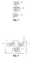
- FIG. 2illustrates software modules executed by a control unit of the diesel engine system illustrated in FIG. 1 ;
- FIG. 3illustrates software modules of a combustion manager module
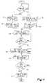
- FIG. 4is a flow chart illustrating representative steps performed by the software modules.
- a system 10that includes an internal combustion engine 12 operatively coupled with an exhaust filtration system 14 .
- the exhaust filtration system 14includes a diesel oxidation catalyst (“DOC”) unit 16 , a diesel particulate filter (“DPF”) 18 and a NO x adsorber or trap 20 .
- DOCdiesel oxidation catalyst
- DPFdiesel particulate filter
- NO x adsorber or trap 20The exhaust filtration system 14 is operable to remove unwanted pollutants from exhaust gas exiting the engine 12 after the combustion process.
- the DOC unit 16is a flow through device that consists of a canister that may contain a honey-comb like structure or substrate.
- the substratehas a large surface area that is coated with an active catalyst layer.
- This layermay contain a small, well dispersed amount of precious metals such as, for example, platinum or palladium.
- As exhaust gas from the engine 12 traverses the catalystCO, gaseous HC and liquid HC particles (unburned fuel and oil) are oxidized, thereby reducing harmful emissions. The result of this process is that these pollutants are converted to carbon dioxide and water.
- the DOC unit 16In order to function properly, the DOC unit 16 must be heated to a minimum temperature value. During engine startup, when the DOC unit 16 is cold, it needs to be heated to the minimum temperature value by the exhaust gas passing through it before it can function properly.
- the DPF 18may comprise one of several type of particle filters known and used in the art.
- the DPF 18is utilized to capture unwanted diesel particulate matter (“DPM”) from the flow of exhaust gas exiting the engine 12 .
- DPMis sub-micron size particles found in diesel exhaust.
- DPMis composed of both solid and liquid particles and is generally classified into three fractions: (1) inorganic carbon (soot), (2) organic fraction (often referred to as SOF or VOF), and (3) sulfate fraction (hydrated sulfuric acid).
- the DPF 18may be regenerated at regular intervals by combusting the particulates collected in the DPF 18 through exhaust manipulation or the like.
- Those skilled in the artwould appreciate that, as it relates to the present invention, several different types of DPFs 16 may be utilized in the present invention n.
- the NO x adsorber 20is operable to absorb NO x created during the combustion process of the engine 12 , thereby reducing the amount of NO x released into the atmosphere to acceptable levels.
- the NO x adsorber 20contains a catalyst that allows NO x to adsorb onto the catalyst. The process of adsorption releases carbon dioxide (“CO 2 ”).
- the NO x adsorber 20stores or absorbs NO x under lean engine operating conditions (lambda>1) and releases and catalytically reduces the stored NO x under rich engine operating conditions (lambda ⁇ 1). Under regeneration or when the engine is operating under a rich condition, two reactions happen. First, the catalyst releases the NO x and is thereby regenerated.
- the NO x adsorber 20also has a high affinity for trapping sulfur and desulfation, the process for removal of sulfur, also requires rich operation, but for a longer period of time and at much higher temperatures.
- ambient airis inducted from the atmosphere and compressed by a compressor 22 of a turbocharger 23 before being supplied to the engine 12 .
- the compressed airis supplied to the engine 12 through an intake manifold 24 that is connected with the engine 12 .
- An air intake throttle valve 26is positioned in the fluid path between the compressor 22 and the engine 12 that is operable to control the amount of charge air that reaches the engine 12 from the compressor 22 .
- the air intake throttle valve 26may be connected with, and controlled by, an electronic control unit (“ECU”) 28 , but may be controlled by other means as well.
- ECUelectronice control unit
- it is important to note that the air intake throttle valve 26is operable to control the amount of charge air entering the intake manifold 24 by way of the compressor 22 .
- An air intake sensor 30is included either before or after the compressor 22 to monitor the amount of ambient air or charge air being supplied to the intake manifold 24 .
- the air intake sensor 30may be connected with the ECU 28 and generates electric signals indicative of the amount of charge air flow.
- An intake manifold pressure sensor 32is connected with the intake manifold 24 .
- the intake manifold pressure sensor 32is operative to sense the amount of charge air pressure in the intake manifold 24 .
- the intake manifold pressure sensor 32is connected with the ECU 28 and generates electric signals indicative of the pressure value that are sent or communicated to the ECU 28 .
- the system 10may also include a fuel injection system 34 that is connected with, and controlled by, the ECU 28 .
- the purpose of the fuel injection system 30is to deliver fuel to the cylinders of the engine 12 , while precisely controlling the timing of the fuel injection, the amount of quantity of fuel injected, fuel atomization, as well as other parameters.
- Fuelis injected into the cylinders of the engine 12 through one or more fuel injectors 36 and combines and is combusted with charge air received from the intake manifold 24 .
- Various types of fuel injection systemsmay be utilized in the present invention, including, but not limited to, pump-line-nozzle injection systems, unit injector and unit pump systems, rail fuel injection systems and so forth.
- Exhaust gases produced in each cylinder during combustionleaves the engine 12 through an exhaust manifold 38 connected with the engine 12 .
- a portion of the exhaust gasis directed to an exhaust gas recirculation (“EGR”) system 40 the remaining portion is supplied to a turbine 42 .
- the turbocharger 23may be a variable geometry turbocharger 23 , but other turbochargers may be utilized as well.
- the EGR system 34is used to cool down the combustion process by providing a predetermined amount of exhaust gas to the charge air being supplied by the compressor 22 . Cooling down the combustion process that occurs in the cylinders of the engine 12 reduces the amount of NO x produced during the combustion process.
- An EGR cooler 41may be included to further cool the exhaust gas before being supplied to the air intake manifold 24 in combination with the compressed air passing through the air intake throttle valve 26 .
- the EGR system 40includes an EGR valve 44 this is positioned in fluid communication with the outlet of the exhaust manifold 38 and the air intake manifold 24 .
- the EGR valve 44may also be connected to the ECU 28 , which is capable of selectively or controllably opening and closing the EGR valve 44 or controlling the range or setting at which the EGR valve 44 is opened.
- the EGR valve 44may also have incorporated therewith a differential pressure sensor that is operable to sense a pressure change, or delta pressure, across the EGR valve 44 .
- a pressure signal 46may also be sent to the ECU 28 indicative of the change in pressure across the EGR valve 44 .
- the portion of the exhaust gas not communicated to the EGR system 40is communicated to the turbine 42 , which rotates by expansion of gases flowing through the turbine 42 .
- the turbine 42is connected to the compressor 22 and provides the driving force for the compressor 22 that generates charge air supplied to the air intake manifold 24 .
- Some temperature loss in the exhaust gastypically occurs as the exhaust gas passes through the turbine 42 .
- As the exhaust gas leaves the turbine 42it is directed to the exhaust filtration system 14 where it is treated before exiting the system 10 .
- a cooling system 48may be connected with the engine 12 .
- the cooling system 48is a liquid cooling system that transfers waste heat out of the block and other internal components of the engine 12 .
- the cooling system 48consists of a closed loop similar to that of an automobile engine.
- Major components of the cooling systemmost of which are not illustrated but well known in the art, include a water pump, radiator or heat exchanger, water jacket (which consists of coolant passages in the block and heads), and a thermostat.
- the thermostat 50which is the only component illustrated in FIG. 1 , is connected with the ECU 28 .
- the thermostat 50generates a signal that is sent to the ECU 28 that indicates the temperature of the coolant used to cool the engine 12 .
- the system 10includes a doser 52 that may be located in the exhaust manifold 38 and/or located downstream of the exhaust manifold 38 .
- the doser 52may comprise an injector mounted in an exhaust conduit 54 .
- the agent introduced through the doser 52is diesel fuel; however, other embodiments are contemplated in which one or more different dosing agents are used in addition to or in lieu of diesel fuel. As set forth below, dosing could occur at a different location from that illustrated.
- a fuel-rich settingcould be provided by appropriate activation of the injectors 36 that provide fuel to the engine 12 in such a manner that the engine 12 produces exhaust including a controlled amount of un-combusted (or incompletely combusted) fuel (in-cylinder dosing or post-injection fueling).
- Doser 52is in fluid communication with a fuel line coupled to the same or a different fuel source (not shown) than that used to fuel the engine 12 and is also connected with the ECU 28 , which controls operation of the doser 52 .
- the system 10also includes a number of sensors and sensing systems for providing the ECU 28 with information relating to the system 10 .
- An engine speed sensor 56may be included in or associated with the engine 12 and is connected with the ECU 28 .
- the engine speed sensor 56is operable to produce an engine speed signal indicative of engine rotation speed that is provided to the ECU 28 .
- a pressure sensor 58may be connected with the exhaust conduit 54 for measuring the pressure of the exhaust before it enters the exhaust filtration system 14 .
- the pressure sensor 58may be connected with the ECU 28 . If pressure becomes too high, this may indicate that a problem exists with the exhaust filtration system 14 , which may be communicated to the ECU 28 .
- At least one temperature sensor 60may be connected with the DOC unit 16 for measuring the temperature of the exhaust gas as it enters the DOC unit 16 .
- two temperature sensors 60may be used, one at the entrance of the DOC unit 16 and one at the exit of the DOC unit 16 , for calculating the operating temperature of the DOC unit 16 .
- an averagemay be determined, using an algorithm, from the two respective temperature readings of the temperature sensors 60 to arrive at an operating temperature of the DOC unit 16 .
- At least one temperature sensor 62may be connected with the DPF 18 and/or the NO x adsorber 20 and the ECU 28 . These temperature sensors 62 monitor the operating temperature of the DPF 18 and/or the NO x adsorber 20 and provide electric signals that are indicative of the operating temperatures to the ECU 28 .
- the system 10includes an ignition module or software routine 100 , a combustion manager module or software routine 102 and a charge manager module or software routine 104 that are executable by the ECU 28 .
- the ignition module 100is operable to monitor one or more parameters indicative of the engine 12 being started or that ignition has occurred.
- the parameters monitoredcould be chosen from one of several parameters known in the art.
- the ignition module 100could use the engine speed reading generated by the engine speed sensor 56 to determine when the engine is started.
- the combustion manager module 102consists of computer executable code that is operable to set target values to manage the combustion process of the engine 12 .
- the combustion manager module 102may set target output values for, amongst other parameters, the amount of charge air flow and EGR flow that is permitted to enter the air intake manifold 24 .
- the combustion manager module 102may include a charge air flow manager module 110 and an EGR flow manager module 112 .
- the target charge air flow supplied by the compressor 22will hereinafter be referred to as the fresh air flow target (“FAFT”).
- FFTfresh air flow target
- the manner in which the EGR flow rate is controlled by the EGR system 40is set forth in detail below.
- the charge air flow manager module 110sets the FAFT to a reduced target value (“FAFT R ”), which is represented at step 122 .
- FAFT Ris equal to a calibrated value.
- the calibrated value FAFT Rmay vary from engine to engine depending on various parameters such as the size of the engine, the size of the DOC unit 16 , and the type(s) of catalyst used in the DOC unit 16 , to name a few.
- the calibrated value FAFT Rmay be determined, for example, during laboratory testing of the engine 12 and exhaust filtration system 14 to determine an optimal setting for each particular type of engine 12 .
- FAFT Ris determined dynamically as a function of one or more engine operating conditions.
- FAFT Rmay be determined as a function of the coolant temperature (“CT”) in the cooling system 48 , the engine speed (“RPM”), and a fueling value.
- CTcoolant temperature
- RPMengine speed
- FAFT Rf(CT, RPM, Fueling) in this embodiment.
- the temperature of the coolantmay be obtained by the ECU 28 from the temperature sensor 50 in the cooling system 48 and the engine speed may be obtained by the ECU 28 from the speed sensor 56 .
- the combustion manager module 102keeps track of the fueling value.
- the charge manager module 104sets the air intake throttle valve 26 to an appropriate setting to achieve the FAFT R , which is represented at step 124 .
- the ECU 28is connected with the air intake throttle valve 26 and is therefore capable of controlling its respective setting, thereby controlling the amount of fresh or compressed air entering the air intake manifold 22 .
- EGRV OLis equal to a calibrated value.
- the calibrated value EGRV OLmay vary from engine to engine depending on various parameters such as the size of the engine, the size of the DOC unit 16 , and the type(s) of catalyst used in the DOC unit 16 , to name a few.
- the calibrated value EGRV OLmay be determined, for example, during laboratory testing of the engine 12 and exhaust filtration system 14 to determine an optimal setting for each particular type of engine 12 .
- EGRV OLis determined dynamically as a function of one or more engine operating conditions.
- EGRV OLmay be determined as a function of the coolant temperature (“CT”) in the cooling system 48 , the engine speed (“RPM”), and a fueling value.
- CTcoolant temperature
- RPMengine speed
- EGRV OLf(CT, RPM, Fueling) in this embodiment.
- the temperature of the coolantmay be obtained by the ECU 28 from the temperature sensor 50 in the cooling system 48 and the engine speed may be obtained by the ECU 28 from the speed sensor 56 .
- the charge manager module 104sets the EGR valve 44 to the EGRV OL .
- the EGR valve 44is connected with the ECU 28 , which is operable to, amongst other things, control the positioning (i.e.—the size of the opening) of the EGR valve 44 . This allows the ECU 28 to control the amount of exhaust gas recirculated to the air intake manifold 24 .
- steps 122 - 128 set forth abovereduces the charge flow supplied to the intake manifold 24 , and in turn, the charge flow supplied to the engine 12 , which causes the engine 12 to work harder and therefore heat up more rapidly. This also increases the temperature of the exhaust gas. Because the engine 12 heats up faster, the DOC unit 16 likewise heats up faster and therefore reaches its optimum operating temperature quicker instead of over an extended period of time. Quickly warming the DOC unit 16 to its optimum operating temperature reduces the amount of harmful pollutants that are expelled from the exhaust filtration system 14 .
- the ECU 28may use the temperature sensor 60 of the DOC unit 16 to continuously monitor, or monitor at predetermined time intervals, the temperature of the exhaust gas as it enters the DOC unit 16 , which is represented at step 130 .
- T TH1a first calibrated threshold temperature value
- post-injection fueling commandsare modified or initiated, as set forth in detail below.
- the combustion manager module 102includes an injection manager module 114 .
- the injection manager module 114is operable to generate signals that are sent by the ECU 28 to the fuel system 34 , thereby controlling the injection of fuel by the injectors 36 .
- the fuel system 34controls how and when fuel is injected into the cylinders of the engine 12 by the fuel injectors 36 and is controlled by the ECU 28 .
- fuelis injected by the fuel injectors 36 into the cylinder of the engine 12 , where it mixes with charge air in the cylinder that is supplied to the engine 12 through the air intake manifold 24 , and once this mixture is placed under a predetermined amount of compression by the piston of the engine 12 , combustion of the fuel/charge air mixture occurs thereby producing energy that drives the piston and other related components.
- fuelmay also be injected into the cylinder during the exhaust cycle (i.e.—as the combusted material exits the cylinder through the exhaust manifold 52 ).
- post-injection fuelingThe process of injecting fuel into the cylinders of the engine 12 with the fuel injectors 36 after combustion has occurred in the cylinder is referred to herein as “post-injection fueling”.
- T TH1a first calibrated threshold temperature value
- post-injection fueling commandsare modified or initiated by the ECU 28 .
- the injection manager module 114instructs the fuel system 34 to set post-injection fueling to a predetermined calibrated level. If post-injection fueling is currently not enabled, the injection manager module 114 causes the fuel system 34 to begin post-injection fueling at the predetermined calibrated level.
- this stepresults in setting or increasing the current post-injection fueling level to the calibrated level.
- the amount or quantity of fuel injected during the post-injection fueling processis calibrated to a predetermined level that is designed to produce an optimal quantity of optimal-length HCs.
- the injection manager module 114may also instruct the fuel system 34 to adjust a timing value associated with post-injection fueling to affect the length of the HCs.
- the timing valuerelates to the time post-injection fueling occurs after combustion occurs in the cylinder of the engine 12 .
- the goal of step 134is to adjust post-injection quantity, and optionally timing, to produce an optimal quantity of optimal-length HCs. It has been found that unburned HCs raise the temperature of the DOC unit 16 faster.
- the extent of post-injection fueling and/or timingvaries from engine to engine and application to application, and the optimal settings may be determined by experimentation with each particular engine design.
- the ECU 28uses the temperature sensor 60 of the DOC unit 16 to monitor the temperature of the exhaust gas as it enters the DOC unit 16 , which is represented at step 136 .
- T TH2a second calibrated threshold temperature value
- FAFT Ra normal or regular operating value
- the EGR system 40is returned to a normal or regular operating setting or position.
- step 134 abovemay be replaced by using one or more of the dosers 52 to inject fuel or another substance into the exhaust flow to increase the amount of HCs in the exhaust gas flowing to the DOC unit 16 .
- both the dosers 52 and step 134 as described abovemay be used simultaneously.
- the amount of fuel introduced by the doser(s) 52 during engine startupis a calibrated value determined on an application by application basis depending on several factors.
- the system 10 disclosed aboveis operable to rapidly heat the diesel oxidation catalyst unit 16 to an effective operating temperature so that it may perform its filtering functions in an optimum manner.
- the present inventiondiscloses a method of rapidly heating a diesel oxidation catalyst unit 16 to an effective operating temperature.
- the methodincludes detecting ignition of an engine 12 , lowering a fresh air target value associated with the engine 12 to a reduced fresh air target value, lowering an exhaust gas recirculation valve opening limit to a reduce exhaust gas recirculation opening limit, monitoring a temperature value associated with a flow of exhaust entering the diesel engine oxidation catalyst unit 16 , post-injecting a predetermined quantity of fuel once the flow of exhaust exceeds a first calibrated threshold temperature value, and setting the engine 12 to a normal operation mode once the flow of exhaust exceeds a second calibrated threshold temperature value.
- the electronic control unit 28comprises an electronic control unit usable medium having computer readable program code embodied in the medium for rapidly heating a diesel oxidation catalyst unit 16 to an effective operating temperature at engine startup.
- the electronic control unit producthas computer readable program code for setting a fresh air target value to a reduced value thereby reducing an amount of charge air supplied to the engine 12 , computer readable program code for setting an exhaust gas recirculation valve 44 to a reduced opening limit thereby reducing an amount of exhaust gas recirculated to the engine 12 , computer readable program code for obtaining a temperature value associated with a flow of exhaust entering the diesel oxidation catalyst unit, computer readable program code for post-injecting a predetermined quantity of fuel once the flow of exhaust exceeds a first calibrated threshold temperature value, and computer readable program code for setting the engine 12 to a normal operating mode once the flow of exhaust exceeds a second calibrated threshold temperature value.
- Yet another aspect of the present inventiondiscloses a system comprising an engine 12 in fluid communication with a diesel oxidation catalyst unit 16 , a fuel system 34 connected with the engine 12 controllably operable to inject fuel into the engine 12 at predetermined intervals, an electronic control unit 28 connected with the fuel system 34 , means for detecting starting of the engine 12 , means for reducing charge air flow supplied by a compressor 22 and an exhaust gas recirculation system 40 to the engine 12 , means for determining when a flow of exhaust entering the diesel oxidation catalyst unit 16 reaches a first threshold temperature value, means for post-injecting a predetermined quantity of fuel into the engine 12 after combustion occurs in the engine once the flow of exhaust reaches the first threshold temperature value, and means for returning the engine 12 to normal operation once the flow of exhaust reaches a second threshold temperature value.
Landscapes
- Engineering & Computer Science (AREA)
- Chemical & Material Sciences (AREA)
- Combustion & Propulsion (AREA)
- Mechanical Engineering (AREA)
- General Engineering & Computer Science (AREA)
- Exhaust Gas After Treatment (AREA)
- Combined Controls Of Internal Combustion Engines (AREA)
Abstract
Description
Claims (25)
Priority Applications (1)
| Application Number | Priority Date | Filing Date | Title |
|---|---|---|---|
| US11/593,722US7654079B2 (en) | 2006-11-07 | 2006-11-07 | Diesel oxidation catalyst filter heating system |
Applications Claiming Priority (1)
| Application Number | Priority Date | Filing Date | Title |
|---|---|---|---|
| US11/593,722US7654079B2 (en) | 2006-11-07 | 2006-11-07 | Diesel oxidation catalyst filter heating system |
Publications (2)
| Publication Number | Publication Date |
|---|---|
| US20080104945A1 US20080104945A1 (en) | 2008-05-08 |
| US7654079B2true US7654079B2 (en) | 2010-02-02 |
Family
ID=39358512
Family Applications (1)
| Application Number | Title | Priority Date | Filing Date |
|---|---|---|---|
| US11/593,722Active2027-03-31US7654079B2 (en) | 2006-11-07 | 2006-11-07 | Diesel oxidation catalyst filter heating system |
Country Status (1)
| Country | Link |
|---|---|
| US (1) | US7654079B2 (en) |
Cited By (7)
| Publication number | Priority date | Publication date | Assignee | Title |
|---|---|---|---|---|
| US20100083639A1 (en)* | 2008-10-03 | 2010-04-08 | Gm Global Technology Operations, Inc. | Apparatus and Method for Optimizing Exhaust Temperature Control in a Vehicle During Particulate Filter Regneration |
| US8412442B2 (en)* | 2011-06-21 | 2013-04-02 | Ford Global Technologies, Llc | Method of engine starting |
| US8832957B2 (en) | 2012-07-26 | 2014-09-16 | Caterpillar Inc. | Apparatus and method for determining ash height in a filter |
| CN111830190A (en)* | 2020-07-23 | 2020-10-27 | 安徽江淮汽车集团股份有限公司 | Calibration method, device, equipment and storage medium for oxidation type catalyst |
| US11053834B2 (en) | 2015-09-29 | 2021-07-06 | Carrier Corporation | Transportation refrigeration system comprising a refrigeration unit and a diesel engine |
| US11242809B2 (en) | 2019-05-01 | 2022-02-08 | Achates Power, Inc. | Exhaust catalyst light-off in an opposed-piston engine |
| US11434797B2 (en) | 2017-04-28 | 2022-09-06 | Cummins Inc. | Methods and systems for removing deposits in an aftertreatment system to minimize visible smoke emissions |
Families Citing this family (11)
| Publication number | Priority date | Publication date | Assignee | Title |
|---|---|---|---|---|
| WO2009130800A1 (en)* | 2008-04-25 | 2009-10-29 | トヨタ自動車株式会社 | Exhaust purification system for internal combustion engine |
| US8534050B2 (en)* | 2009-12-18 | 2013-09-17 | GM Global Technology Operations LLC | Exhaust gas aftertreatment system for a diesel engine and method of increasing a temperature of an SCR catalyst to reduce NOx in exhaust gases |
| DE102010003705A1 (en)* | 2010-04-08 | 2011-10-13 | Robert Bosch Gmbh | Method for heating a catalytic converter in an engine system and for diagnosing the effectiveness of measures for heating the catalytic converter |
| US8935918B2 (en)* | 2010-04-23 | 2015-01-20 | GM Global Technology Operations LLC | Reconfigurable mixer for an exhaust aftertreatment system and method of using the same |
| GB2490522A (en)* | 2011-05-04 | 2012-11-07 | T Baden Hardstaff Ltd | Exhaust system for a dual fuel engine |
| GB2504358B (en) | 2012-07-27 | 2016-02-24 | Perkins Engines Co Ltd | Method of controlling operation of an exhaust fluid treatment apparatus |
| EP3025037A4 (en)* | 2013-07-23 | 2017-03-01 | Mahindra & Mahindra Ltd. | Naturally aspirated common rail diesel engine meeting ultra low pm emission by passive exhaust after treatment |
| US10378405B2 (en)* | 2016-01-20 | 2019-08-13 | Deere & Company | Method for managing temperatures in aftertreatment system |
| GB2550422B (en) | 2016-05-20 | 2019-12-04 | Caterpillar Inc | Method of controlling operation of an exhaust gas treatment apparatus |
| US11002205B2 (en)* | 2019-07-22 | 2021-05-11 | Caterpillar Inc. | Regeneration control system for oxidation catalyst regeneration in internal combustion engine |
| CN119712288A (en)* | 2025-03-04 | 2025-03-28 | 中国重汽集团济南动力有限公司 | Diesel engine aftertreatment system, vehicle and control method |
Citations (88)
| Publication number | Priority date | Publication date | Assignee | Title |
|---|---|---|---|---|
| US4222236A (en) | 1978-06-19 | 1980-09-16 | General Motors Corporation | Method for reducing CO and HC emissions |
| US5473887A (en) | 1991-10-03 | 1995-12-12 | Toyota Jidosha Kabushiki Kaisha | Exhaust purification device of internal combustion engine |
| US5529048A (en) | 1991-04-20 | 1996-06-25 | Yamaha Hatsudoki Kabushiki Kaisha | Fuel control and feed system for gas fueled engine |
| US5531203A (en) | 1994-01-25 | 1996-07-02 | Honda Giken Kogyo Kabushiki Kaisha | Catalyst activating system in multi-cylinder internal combustion engine |
| US5600947A (en) | 1995-07-05 | 1997-02-11 | Ford Motor Company | Method and system for estimating and controlling electrically heated catalyst temperature |
| US5635142A (en) | 1993-08-24 | 1997-06-03 | Hitachi Zosen Corporation | NOx adsorption and removal apparatus |
| US5743084A (en) | 1996-10-16 | 1998-04-28 | Ford Global Technologies, Inc. | Method for monitoring the performance of a nox trap |
| US5784879A (en) | 1995-06-30 | 1998-07-28 | Nippondenso Co., Ltd. | Air-fuel ratio control system for internal combustion engine |
| US5878567A (en) | 1996-01-22 | 1999-03-09 | Ford Global Technologies, Inc. | Closely coupled exhaust catalyst system and engine strategy associated therewith |
| US5894725A (en) | 1997-03-27 | 1999-04-20 | Ford Global Technologies, Inc. | Method and apparatus for maintaining catalyst efficiency of a NOx trap |
| US5915359A (en) | 1996-12-13 | 1999-06-29 | Ford Global Technologies, Inc. | Method and system for determining and controlling A/F ratio during cold start engine operation |
| US5992142A (en)* | 1996-09-28 | 1999-11-30 | Volkswagen Ag | No exhaust emission control method and arrangement |
| US6185935B1 (en) | 1998-04-21 | 2001-02-13 | Ford Motor Company | Method and apparatus for controlling the temperature of an exhaust gas treatment system |
| US6199372B1 (en) | 1996-04-26 | 2001-03-13 | Komatsu Ltd. | Apparatus and method for regenerating NOx catalyst for diesel engine |
| US6202406B1 (en) | 1998-03-30 | 2001-03-20 | Heralus Electro-Nite International N.V. | Method and apparatus for catalyst temperature control |
| US6205773B1 (en) | 1998-07-07 | 2001-03-27 | Toyota Jidosha Kabushiki Kaisha | Exhaust gas purification device for an internal combustion engine |
| US6209515B1 (en)* | 1998-07-15 | 2001-04-03 | Toyota Jidosha Kabushiki Kaisha | Internal combustion engine, controller and method |
| US6212884B1 (en) | 1999-03-09 | 2001-04-10 | Mitsubishi Denki Kabushiki Kaisha | Device for controlling the rise of the catalyst temperature in an internal combustion engine |
| US6216449B1 (en) | 1998-04-14 | 2001-04-17 | Degussa Ag | Process for evaluating performance deterioration of a nitrogen oxide storage catalyst |
| US6240723B1 (en)* | 1997-12-04 | 2001-06-05 | Toyota Jidosha Kabushiki Kaisha | Compression ignition type engine |
| US6244046B1 (en) | 1998-07-17 | 2001-06-12 | Denso Corporation | Engine exhaust purification system and method having NOx occluding and reducing catalyst |
| US6266957B1 (en) | 1998-03-25 | 2001-07-31 | Denso Corporation | Catalyst activation control system for engines |
| US20010010149A1 (en) | 2000-01-27 | 2001-08-02 | Honda Giken Kogyo Kabushiki Kaisha | Control system for internal combustion engine |
| US6272848B1 (en) | 1997-07-17 | 2001-08-14 | Hitachi, Ltd. | Exhaust gas cleaning apparatus and method for internal combustion engine |
| US20010013223A1 (en) | 1999-12-15 | 2001-08-16 | Walter Boegner | Exhaust-gas cleaning system with nitrogen oxide accumulator catalyst and sulphur oxide trap and operating method therefor |
| US20010032456A1 (en) | 1999-06-03 | 2001-10-25 | Tosiaki Yonekura | Exhaust gas purifier for internal combustion engine |
| US6308515B1 (en) | 2000-03-17 | 2001-10-30 | Ford Global Technologies, Inc. | Method and apparatus for accessing ability of lean NOx trap to store exhaust gas constituent |
| US6311482B1 (en) | 1999-08-09 | 2001-11-06 | Denso Corporation | Air-fuel ratio control apparatus for internal combustion engines |
| US6318075B1 (en) | 1999-03-10 | 2001-11-20 | Daimler Chrysler Ag | Method and device for periodically desulphating a nitrogen oxide or sulphur oxide storage vessel with rich/lean engine cylinder distribution |
| US6327848B1 (en) | 1999-09-07 | 2001-12-11 | Magneti Marelli S.P.A | Self-adapting control method for an exhaust system for internal combustion engines with controlled ignition |
| US6327847B1 (en) | 2000-03-17 | 2001-12-11 | Ford Global Technologies, Inc. | Method for improved performance of a vehicle |
| US6360530B1 (en) | 2000-03-17 | 2002-03-26 | Ford Global Technologies, Inc. | Method and apparatus for measuring lean-burn engine emissions |
| US6370868B1 (en) | 2000-04-04 | 2002-04-16 | Ford Global Technologies, Inc. | Method and system for purge cycle management of a lean NOx trap |
| US6374597B1 (en) | 2000-03-17 | 2002-04-23 | Ford Global Technologies, Inc. | Method and apparatus for accessing ability of lean NOx trap to store exhaust gas constituent |
| US20020056268A1 (en) | 1999-09-11 | 2002-05-16 | Honda Giken Kogyo Kabushiki Kaisha | Control system for internal combustion engine |
| US6389802B1 (en) | 1998-09-25 | 2002-05-21 | Robert Bosch Gmbh | Method and arrangement for operating an internal combustion engine in combination with an NOx storage catalytic converter and an NOx sensor |
| US6401454B2 (en) | 1999-03-19 | 2002-06-11 | Hitachi, Ltd. | Engine control device |
| US20020073696A1 (en) | 2000-11-03 | 2002-06-20 | Johannes Kuenstler | Method for regenerating a diesel particulate filter |
| US6422003B1 (en) | 2000-11-15 | 2002-07-23 | General Motors Corporation | NOX catalyst exhaust feedstream control system |
| US6422004B1 (en)* | 1999-09-22 | 2002-07-23 | Mazda Motor Corporation | System for controlling engine |
| US6427439B1 (en) | 2000-07-13 | 2002-08-06 | Ford Global Technologies, Inc. | Method and system for NOx reduction |
| US6434928B1 (en) | 2000-02-28 | 2002-08-20 | Hitachi, Ltd. | Apparatus and method of purification of exhaust emission of internal combustion engine |
| US6438944B1 (en) | 2000-03-17 | 2002-08-27 | Ford Global Technologies, Inc. | Method and apparatus for optimizing purge fuel for purging emissions control device |
| US6451602B1 (en) | 2000-03-02 | 2002-09-17 | Isis Pharmaceuticals, Inc. | Antisense modulation of PARP expression |
| US6453663B1 (en) | 2001-08-16 | 2002-09-24 | Ford Global Technologies, Inc | NOx sensor monitoring |
| US20020141908A1 (en) | 2000-02-22 | 2002-10-03 | Seiji Miyoshi | Device for purifying exhaust gas, method for purifying exhaust gas, catalyst for purifying exhaust gas, and method for manufacturing exhaust gas purifying catalyst |
| US6463733B1 (en) | 2001-06-19 | 2002-10-15 | Ford Global Technologies, Inc. | Method and system for optimizing open-loop fill and purge times for an emission control device |
| US6467259B1 (en) | 2001-06-19 | 2002-10-22 | Ford Global Technologies, Inc. | Method and system for operating dual-exhaust engine |
| US6477832B1 (en) | 2000-03-17 | 2002-11-12 | Ford Global Technologies, Inc. | Method for improved performance of a vehicle having an internal combustion engine |
| US6481199B1 (en) | 2000-03-17 | 2002-11-19 | Ford Global Technologies, Inc. | Control for improved vehicle performance |
| US20020170287A1 (en) | 2000-07-24 | 2002-11-21 | Shinya Hirota | Exhaust gas purification device |
| US6487849B1 (en) | 2000-03-17 | 2002-12-03 | Ford Global Technologies, Inc. | Method and apparatus for controlling lean-burn engine based upon predicted performance impact and trap efficiency |
| US6487850B1 (en) | 2000-03-17 | 2002-12-03 | Ford Global Technologies, Inc. | Method for improved engine control |
| US20020178716A1 (en) | 2001-12-18 | 2002-12-05 | Hepburn Jeffrey Scott | System and method for removing NOx from an emission control device |
| US6490858B2 (en) | 2001-02-16 | 2002-12-10 | Ashley J. Barrett | Catalytic converter thermal aging method and apparatus |
| US6490860B1 (en) | 2001-06-19 | 2002-12-10 | Ford Global Technologies, Inc. | Open-loop method and system for controlling the storage and release cycles of an emission control device |
| US20020189235A1 (en) | 2001-06-19 | 2002-12-19 | Meyer Garth Michael | Method and system for controlling a regeneration cycle of an emission control device |
| US20020189580A1 (en) | 2001-06-19 | 2002-12-19 | Gopichandra Surnilla | Method and system for transitioning between lean and stoichiometric operation of a lean-burn engine |
| US6497092B1 (en) | 1999-03-18 | 2002-12-24 | Delphi Technologies, Inc. | NOx absorber diagnostics and automotive exhaust control system utilizing the same |
| US20030000205A1 (en) | 2001-06-20 | 2003-01-02 | Lewis Donald James | System and method for determining set point location for oxidant-based engine air/fuel control strategy |
| US6502391B1 (en) | 1999-01-25 | 2003-01-07 | Toyota Jidosha Kabushiki Kaisha | Exhaust emission control device of internal combustion engine |
| US6502387B1 (en) | 2001-06-19 | 2003-01-07 | Ford Global Technologies, Inc. | Method and system for controlling storage and release of exhaust gas constituents in an emission control device |
| US20030037541A1 (en) | 2001-06-19 | 2003-02-27 | Farmer David George | Method and system for preconditioning an emission control device for operation about stoichiometry |
| US6531099B1 (en) | 1996-08-19 | 2003-03-11 | Volkswagen Ag | Oxide gas absorbing arrangement and method |
| US20030056497A1 (en) | 2001-09-26 | 2003-03-27 | Johannes Kuenstler | Method for controlling the starting of an internal combustion engine |
| US20030056499A1 (en) | 2001-07-03 | 2003-03-27 | Klaus Binder | Exhaust-gas aftertreatment device with nitrogen oxide storage catalytic converter, and operating method therefor |
| US6568177B1 (en) | 2002-06-04 | 2003-05-27 | Ford Global Technologies, Llc | Method for rapid catalyst heating |
| US20030101713A1 (en) | 2001-12-03 | 2003-06-05 | Ralph Dalla Betta | System and methods for improved emission control of internal combustion engines |
| US20030106307A1 (en) | 1999-07-02 | 2003-06-12 | Mitsubishi Jidosha Kogyo Kabushiki Kaisha | Exhaust gas purifying apparatus of internal combustion engine |
| US20030106306A1 (en) | 2001-12-07 | 2003-06-12 | Toyota Jidosha Kabushiki Kaisha | Exhaust gas purification device |
| US6581372B2 (en)* | 2000-10-04 | 2003-06-24 | Toyota Jidosha Kabushiki Kaisha | Compression ignition type engine |
| US6588205B1 (en) | 1997-05-14 | 2003-07-08 | Mitsubishi Jidosha Kogyo Kabushiki Kaisha | Exhaust gas purifying apparatus |
| US20030134425A1 (en) | 2001-12-14 | 2003-07-17 | Magneti Marelli Powertrain, S.P.A. | Method for estimating the sulfur content in the fuel of an internal combustion engine |
| US20030131591A1 (en) | 1999-12-17 | 2003-07-17 | Ekkehard Pott | Method for desulphurisation of an nox storage accumulator-catalyst arranged in an exhaust system of an internal combustion engine |
| US20030177761A1 (en) | 2000-09-02 | 2003-09-25 | Jens Wagner | Method for heating up catalysts in the exhaust gas of internal combustion engines |
| US20030212484A1 (en) | 2002-03-29 | 2003-11-13 | Mazda Motor Corporation | Diagnostic apparatus for an engine |
| US20030213235A1 (en) | 2002-05-20 | 2003-11-20 | Nissan Motor Co., Ltd. | Exhaust gas apparatus and method for purifying exhaust gas in internal combustion engine |
| US6651422B1 (en) | 1998-08-24 | 2003-11-25 | Legare Joseph E. | Catalyst efficiency detection and heating method using cyclic fuel control |
| US20040003587A1 (en) | 2002-05-16 | 2004-01-08 | Nissan Motor Co., Ltd. | Exhaust gas purifying apparatus and method for internal combustion engine |
| US6823658B2 (en) | 2001-08-28 | 2004-11-30 | Honda Giken Kogyo Kabushiki Kaisha | Exhaust gas purifying apparatus for an internal-combustion engine |
| US6871492B2 (en) | 2001-08-16 | 2005-03-29 | Dr. Ing. H.C.F. Porsche Ag | Process and system for controlling the mixture composition for a spark ignition Otto engine with an NOx storage catalyst during a regeneration phase |
| US6889497B2 (en) | 2000-07-26 | 2005-05-10 | Robert Bosch Gmbh | Method and controller for operating a nitrogen oxide (NOx) storage catalyst |
| US6901749B2 (en) | 2000-08-01 | 2005-06-07 | Honda Giken Kogyo Kabushiki Kaisha | Exhaust emission control system for internal combustion engine |
| US6907862B2 (en)* | 2003-07-30 | 2005-06-21 | Nissan Motor Co., Ltd. | Combustion control apparatus for internal combustion engine |
| US6990799B2 (en) | 2000-03-17 | 2006-01-31 | Ford Global Technologies, Llc | Method of determining emission control system operability |
| US20060137327A1 (en) | 2004-12-28 | 2006-06-29 | Nissan Motor Co., Ltd. | Exhaust gas purification control of diesel engine |
| US7121086B2 (en) | 2001-06-08 | 2006-10-17 | Nissan Motor Co., Ltd. | Desulphating of nitrogen oxide trapping catalyst |
| US7134274B2 (en) | 2004-06-10 | 2006-11-14 | Toyota Jidosha Kabushiki Kaisha | Exhaust gas control apparatus for internal combustion engine |
Family Cites Families (1)
| Publication number | Priority date | Publication date | Assignee | Title |
|---|---|---|---|---|
| JP2003273317A (en)* | 2002-03-19 | 2003-09-26 | Nec Electronics Corp | Semiconductor device and its manufacturing method |
- 2006
- 2006-11-07USUS11/593,722patent/US7654079B2/enactiveActive
Patent Citations (109)
| Publication number | Priority date | Publication date | Assignee | Title |
|---|---|---|---|---|
| US4222236A (en) | 1978-06-19 | 1980-09-16 | General Motors Corporation | Method for reducing CO and HC emissions |
| US5529048A (en) | 1991-04-20 | 1996-06-25 | Yamaha Hatsudoki Kabushiki Kaisha | Fuel control and feed system for gas fueled engine |
| US5473887A (en) | 1991-10-03 | 1995-12-12 | Toyota Jidosha Kabushiki Kaisha | Exhaust purification device of internal combustion engine |
| US5635142A (en) | 1993-08-24 | 1997-06-03 | Hitachi Zosen Corporation | NOx adsorption and removal apparatus |
| US5531203A (en) | 1994-01-25 | 1996-07-02 | Honda Giken Kogyo Kabushiki Kaisha | Catalyst activating system in multi-cylinder internal combustion engine |
| US5784879A (en) | 1995-06-30 | 1998-07-28 | Nippondenso Co., Ltd. | Air-fuel ratio control system for internal combustion engine |
| US5600947A (en) | 1995-07-05 | 1997-02-11 | Ford Motor Company | Method and system for estimating and controlling electrically heated catalyst temperature |
| US5878567A (en) | 1996-01-22 | 1999-03-09 | Ford Global Technologies, Inc. | Closely coupled exhaust catalyst system and engine strategy associated therewith |
| US6199372B1 (en) | 1996-04-26 | 2001-03-13 | Komatsu Ltd. | Apparatus and method for regenerating NOx catalyst for diesel engine |
| US6531099B1 (en) | 1996-08-19 | 2003-03-11 | Volkswagen Ag | Oxide gas absorbing arrangement and method |
| US5992142A (en)* | 1996-09-28 | 1999-11-30 | Volkswagen Ag | No exhaust emission control method and arrangement |
| US5743084A (en) | 1996-10-16 | 1998-04-28 | Ford Global Technologies, Inc. | Method for monitoring the performance of a nox trap |
| US5915359A (en) | 1996-12-13 | 1999-06-29 | Ford Global Technologies, Inc. | Method and system for determining and controlling A/F ratio during cold start engine operation |
| US5894725A (en) | 1997-03-27 | 1999-04-20 | Ford Global Technologies, Inc. | Method and apparatus for maintaining catalyst efficiency of a NOx trap |
| US6588205B1 (en) | 1997-05-14 | 2003-07-08 | Mitsubishi Jidosha Kogyo Kabushiki Kaisha | Exhaust gas purifying apparatus |
| US6272848B1 (en) | 1997-07-17 | 2001-08-14 | Hitachi, Ltd. | Exhaust gas cleaning apparatus and method for internal combustion engine |
| US6240723B1 (en)* | 1997-12-04 | 2001-06-05 | Toyota Jidosha Kabushiki Kaisha | Compression ignition type engine |
| US6513319B2 (en) | 1998-03-25 | 2003-02-04 | Denso Corporation | Catalyst activation control system for engines |
| US20010035008A1 (en) | 1998-03-25 | 2001-11-01 | Denso Corporation | Catalyst activation control system for engines |
| US6266957B1 (en) | 1998-03-25 | 2001-07-31 | Denso Corporation | Catalyst activation control system for engines |
| US6202406B1 (en) | 1998-03-30 | 2001-03-20 | Heralus Electro-Nite International N.V. | Method and apparatus for catalyst temperature control |
| US6216449B1 (en) | 1998-04-14 | 2001-04-17 | Degussa Ag | Process for evaluating performance deterioration of a nitrogen oxide storage catalyst |
| US6185935B1 (en) | 1998-04-21 | 2001-02-13 | Ford Motor Company | Method and apparatus for controlling the temperature of an exhaust gas treatment system |
| US6205773B1 (en) | 1998-07-07 | 2001-03-27 | Toyota Jidosha Kabushiki Kaisha | Exhaust gas purification device for an internal combustion engine |
| US6209515B1 (en)* | 1998-07-15 | 2001-04-03 | Toyota Jidosha Kabushiki Kaisha | Internal combustion engine, controller and method |
| US6244046B1 (en) | 1998-07-17 | 2001-06-12 | Denso Corporation | Engine exhaust purification system and method having NOx occluding and reducing catalyst |
| US6651422B1 (en) | 1998-08-24 | 2003-11-25 | Legare Joseph E. | Catalyst efficiency detection and heating method using cyclic fuel control |
| US6389802B1 (en) | 1998-09-25 | 2002-05-21 | Robert Bosch Gmbh | Method and arrangement for operating an internal combustion engine in combination with an NOx storage catalytic converter and an NOx sensor |
| US6502391B1 (en) | 1999-01-25 | 2003-01-07 | Toyota Jidosha Kabushiki Kaisha | Exhaust emission control device of internal combustion engine |
| US6212884B1 (en) | 1999-03-09 | 2001-04-10 | Mitsubishi Denki Kabushiki Kaisha | Device for controlling the rise of the catalyst temperature in an internal combustion engine |
| US6513322B2 (en) | 1999-03-09 | 2003-02-04 | Mitsubishi Denki Kabushiki Kaisha | Device for controlling the rise of the catalyst temperature in an internal combustion engine |
| US20010007191A1 (en) | 1999-03-09 | 2001-07-12 | Hirofumi Ohuchi | Device for controlling the rise of the catalyst temperature in an internal combustion engine |
| US6318075B1 (en) | 1999-03-10 | 2001-11-20 | Daimler Chrysler Ag | Method and device for periodically desulphating a nitrogen oxide or sulphur oxide storage vessel with rich/lean engine cylinder distribution |
| US6497092B1 (en) | 1999-03-18 | 2002-12-24 | Delphi Technologies, Inc. | NOx absorber diagnostics and automotive exhaust control system utilizing the same |
| US6401454B2 (en) | 1999-03-19 | 2002-06-11 | Hitachi, Ltd. | Engine control device |
| US20010032456A1 (en) | 1999-06-03 | 2001-10-25 | Tosiaki Yonekura | Exhaust gas purifier for internal combustion engine |
| US6345498B2 (en) | 1999-06-03 | 2002-02-12 | Mitsubishi Denki Kabushiki Kaisha | Exhaust gas purifier for internal combustion engine |
| US6644021B2 (en) | 1999-07-02 | 2003-11-11 | Mitsubishi Jidosha Kogyo Kabushiki Kaisha | Exhaust gas purifying apparatus of internal combustion engine |
| US20030106307A1 (en) | 1999-07-02 | 2003-06-12 | Mitsubishi Jidosha Kogyo Kabushiki Kaisha | Exhaust gas purifying apparatus of internal combustion engine |
| US6311482B1 (en) | 1999-08-09 | 2001-11-06 | Denso Corporation | Air-fuel ratio control apparatus for internal combustion engines |
| US6327848B1 (en) | 1999-09-07 | 2001-12-11 | Magneti Marelli S.P.A | Self-adapting control method for an exhaust system for internal combustion engines with controlled ignition |
| US20020056268A1 (en) | 1999-09-11 | 2002-05-16 | Honda Giken Kogyo Kabushiki Kaisha | Control system for internal combustion engine |
| US6688101B2 (en) | 1999-09-11 | 2004-02-10 | Honda Giken Kogyo Kabushiki Kaisha | Control system for internal combustion engine |
| US6422004B1 (en)* | 1999-09-22 | 2002-07-23 | Mazda Motor Corporation | System for controlling engine |
| US20010013223A1 (en) | 1999-12-15 | 2001-08-16 | Walter Boegner | Exhaust-gas cleaning system with nitrogen oxide accumulator catalyst and sulphur oxide trap and operating method therefor |
| US6408620B2 (en) | 1999-12-15 | 2002-06-25 | Daimlerchrylser Ag | Exhaust-gas cleaning system with nitrogen oxide accumulator catalyst and sulphur oxide trap and operating method therefor |
| US20030131591A1 (en) | 1999-12-17 | 2003-07-17 | Ekkehard Pott | Method for desulphurisation of an nox storage accumulator-catalyst arranged in an exhaust system of an internal combustion engine |
| US6941748B2 (en) | 1999-12-17 | 2005-09-13 | Volkwagen Ag | Method for desulfurization of an NOx storage accumulator-catalyst arranged in an exhaust system of an internal combustion engine |
| US6453664B2 (en) | 2000-01-27 | 2002-09-24 | Honda Giken Kogyo Kabushiki Kaisha | Control system for internal combustion engine |
| US20010010149A1 (en) | 2000-01-27 | 2001-08-02 | Honda Giken Kogyo Kabushiki Kaisha | Control system for internal combustion engine |
| US20020141908A1 (en) | 2000-02-22 | 2002-10-03 | Seiji Miyoshi | Device for purifying exhaust gas, method for purifying exhaust gas, catalyst for purifying exhaust gas, and method for manufacturing exhaust gas purifying catalyst |
| US6562753B2 (en) | 2000-02-22 | 2003-05-13 | Madza Motor Corporation | Device for purifying exhaust gas, method for purifying exhaust gas, catalyst for purifying exhaust gas, and method for manufacturing exhaust gas purifying catalyst |
| US6434928B1 (en) | 2000-02-28 | 2002-08-20 | Hitachi, Ltd. | Apparatus and method of purification of exhaust emission of internal combustion engine |
| US6451602B1 (en) | 2000-03-02 | 2002-09-17 | Isis Pharmaceuticals, Inc. | Antisense modulation of PARP expression |
| US6481199B1 (en) | 2000-03-17 | 2002-11-19 | Ford Global Technologies, Inc. | Control for improved vehicle performance |
| US6477832B1 (en) | 2000-03-17 | 2002-11-12 | Ford Global Technologies, Inc. | Method for improved performance of a vehicle having an internal combustion engine |
| US6487849B1 (en) | 2000-03-17 | 2002-12-03 | Ford Global Technologies, Inc. | Method and apparatus for controlling lean-burn engine based upon predicted performance impact and trap efficiency |
| US6487850B1 (en) | 2000-03-17 | 2002-12-03 | Ford Global Technologies, Inc. | Method for improved engine control |
| US6990799B2 (en) | 2000-03-17 | 2006-01-31 | Ford Global Technologies, Llc | Method of determining emission control system operability |
| US6308515B1 (en) | 2000-03-17 | 2001-10-30 | Ford Global Technologies, Inc. | Method and apparatus for accessing ability of lean NOx trap to store exhaust gas constituent |
| US6374597B1 (en) | 2000-03-17 | 2002-04-23 | Ford Global Technologies, Inc. | Method and apparatus for accessing ability of lean NOx trap to store exhaust gas constituent |
| US6438944B1 (en) | 2000-03-17 | 2002-08-27 | Ford Global Technologies, Inc. | Method and apparatus for optimizing purge fuel for purging emissions control device |
| US6360530B1 (en) | 2000-03-17 | 2002-03-26 | Ford Global Technologies, Inc. | Method and apparatus for measuring lean-burn engine emissions |
| US6327847B1 (en) | 2000-03-17 | 2001-12-11 | Ford Global Technologies, Inc. | Method for improved performance of a vehicle |
| US6370868B1 (en) | 2000-04-04 | 2002-04-16 | Ford Global Technologies, Inc. | Method and system for purge cycle management of a lean NOx trap |
| US6427439B1 (en) | 2000-07-13 | 2002-08-06 | Ford Global Technologies, Inc. | Method and system for NOx reduction |
| US6823665B2 (en) | 2000-07-24 | 2004-11-30 | Toyota Jidosha Kabushiki Kaisha | Exhaust gas purification device |
| US20020170287A1 (en) | 2000-07-24 | 2002-11-21 | Shinya Hirota | Exhaust gas purification device |
| US6889497B2 (en) | 2000-07-26 | 2005-05-10 | Robert Bosch Gmbh | Method and controller for operating a nitrogen oxide (NOx) storage catalyst |
| US6901749B2 (en) | 2000-08-01 | 2005-06-07 | Honda Giken Kogyo Kabushiki Kaisha | Exhaust emission control system for internal combustion engine |
| US6813879B2 (en) | 2000-09-02 | 2004-11-09 | Robert Bosch Gmbh | Method for heating up catalysts in the exhaust gas of internal combustion engines |
| US20030177761A1 (en) | 2000-09-02 | 2003-09-25 | Jens Wagner | Method for heating up catalysts in the exhaust gas of internal combustion engines |
| US6581372B2 (en)* | 2000-10-04 | 2003-06-24 | Toyota Jidosha Kabushiki Kaisha | Compression ignition type engine |
| US6594990B2 (en) | 2000-11-03 | 2003-07-22 | Ford Global Technologies, Llc | Method for regenerating a diesel particulate filter |
| US20020073696A1 (en) | 2000-11-03 | 2002-06-20 | Johannes Kuenstler | Method for regenerating a diesel particulate filter |
| US6422003B1 (en) | 2000-11-15 | 2002-07-23 | General Motors Corporation | NOX catalyst exhaust feedstream control system |
| US6490858B2 (en) | 2001-02-16 | 2002-12-10 | Ashley J. Barrett | Catalytic converter thermal aging method and apparatus |
| US7121086B2 (en) | 2001-06-08 | 2006-10-17 | Nissan Motor Co., Ltd. | Desulphating of nitrogen oxide trapping catalyst |
| US6467259B1 (en) | 2001-06-19 | 2002-10-22 | Ford Global Technologies, Inc. | Method and system for operating dual-exhaust engine |
| US6502387B1 (en) | 2001-06-19 | 2003-01-07 | Ford Global Technologies, Inc. | Method and system for controlling storage and release of exhaust gas constituents in an emission control device |
| US6490860B1 (en) | 2001-06-19 | 2002-12-10 | Ford Global Technologies, Inc. | Open-loop method and system for controlling the storage and release cycles of an emission control device |
| US20020189235A1 (en) | 2001-06-19 | 2002-12-19 | Meyer Garth Michael | Method and system for controlling a regeneration cycle of an emission control device |
| US20030037541A1 (en) | 2001-06-19 | 2003-02-27 | Farmer David George | Method and system for preconditioning an emission control device for operation about stoichiometry |
| US6615577B2 (en) | 2001-06-19 | 2003-09-09 | Ford Global Technologies, Llc | Method and system for controlling a regeneration cycle of an emission control device |
| US20020189580A1 (en) | 2001-06-19 | 2002-12-19 | Gopichandra Surnilla | Method and system for transitioning between lean and stoichiometric operation of a lean-burn engine |
| US6463733B1 (en) | 2001-06-19 | 2002-10-15 | Ford Global Technologies, Inc. | Method and system for optimizing open-loop fill and purge times for an emission control device |
| US20030000205A1 (en) | 2001-06-20 | 2003-01-02 | Lewis Donald James | System and method for determining set point location for oxidant-based engine air/fuel control strategy |
| US6766642B2 (en) | 2001-07-03 | 2004-07-27 | Daimlerchrysler Ag | Exhaust-gas aftertreatment device with nitrogen oxide storage catalytic converter, and operating method therefor |
| US20030056499A1 (en) | 2001-07-03 | 2003-03-27 | Klaus Binder | Exhaust-gas aftertreatment device with nitrogen oxide storage catalytic converter, and operating method therefor |
| US6453663B1 (en) | 2001-08-16 | 2002-09-24 | Ford Global Technologies, Inc | NOx sensor monitoring |
| US6871492B2 (en) | 2001-08-16 | 2005-03-29 | Dr. Ing. H.C.F. Porsche Ag | Process and system for controlling the mixture composition for a spark ignition Otto engine with an NOx storage catalyst during a regeneration phase |
| US6823658B2 (en) | 2001-08-28 | 2004-11-30 | Honda Giken Kogyo Kabushiki Kaisha | Exhaust gas purifying apparatus for an internal-combustion engine |
| US20030056497A1 (en) | 2001-09-26 | 2003-03-27 | Johannes Kuenstler | Method for controlling the starting of an internal combustion engine |
| US6829888B2 (en) | 2001-09-26 | 2004-12-14 | Ford Global Technologies, Llc | Method for controlling the starting of an internal combustion engine |
| US20030101713A1 (en) | 2001-12-03 | 2003-06-05 | Ralph Dalla Betta | System and methods for improved emission control of internal combustion engines |
| US20030106306A1 (en) | 2001-12-07 | 2003-06-12 | Toyota Jidosha Kabushiki Kaisha | Exhaust gas purification device |
| US6823664B2 (en) | 2001-12-07 | 2004-11-30 | Toyota Jidosha Kabushiki Kaisha | Exhaust gas purification device |
| US20030134425A1 (en) | 2001-12-14 | 2003-07-17 | Magneti Marelli Powertrain, S.P.A. | Method for estimating the sulfur content in the fuel of an internal combustion engine |
| US6813882B2 (en) | 2001-12-18 | 2004-11-09 | Ford Global Technologies, Llc | System and method for removing NOx from an emission control device |
| US20020178716A1 (en) | 2001-12-18 | 2002-12-05 | Hepburn Jeffrey Scott | System and method for removing NOx from an emission control device |
| US6792346B2 (en) | 2002-03-29 | 2004-09-14 | Mazda Motor Corporation | Diagnostic apparatus for an engine |
| US20030212484A1 (en) | 2002-03-29 | 2003-11-13 | Mazda Motor Corporation | Diagnostic apparatus for an engine |
| US20040003587A1 (en) | 2002-05-16 | 2004-01-08 | Nissan Motor Co., Ltd. | Exhaust gas purifying apparatus and method for internal combustion engine |
| US20030213235A1 (en) | 2002-05-20 | 2003-11-20 | Nissan Motor Co., Ltd. | Exhaust gas apparatus and method for purifying exhaust gas in internal combustion engine |
| US6962045B2 (en) | 2002-05-20 | 2005-11-08 | Nissan Motor Co., Ltd. | Exhaust gas apparatus and method for purifying exhaust gas in internal combustion engine |
| US6568177B1 (en) | 2002-06-04 | 2003-05-27 | Ford Global Technologies, Llc | Method for rapid catalyst heating |
| US6907862B2 (en)* | 2003-07-30 | 2005-06-21 | Nissan Motor Co., Ltd. | Combustion control apparatus for internal combustion engine |
| US7134274B2 (en) | 2004-06-10 | 2006-11-14 | Toyota Jidosha Kabushiki Kaisha | Exhaust gas control apparatus for internal combustion engine |
| US20060137327A1 (en) | 2004-12-28 | 2006-06-29 | Nissan Motor Co., Ltd. | Exhaust gas purification control of diesel engine |
Cited By (13)
| Publication number | Priority date | Publication date | Assignee | Title |
|---|---|---|---|---|
| US20100083639A1 (en)* | 2008-10-03 | 2010-04-08 | Gm Global Technology Operations, Inc. | Apparatus and Method for Optimizing Exhaust Temperature Control in a Vehicle During Particulate Filter Regneration |
| US8020372B2 (en)* | 2008-10-03 | 2011-09-20 | GM Global Technology Operations LLC | Apparatus and method for optimizing exhaust temperature control in a vehicle during particulate filter regneration |
| US8412442B2 (en)* | 2011-06-21 | 2013-04-02 | Ford Global Technologies, Llc | Method of engine starting |
| US8832957B2 (en) | 2012-07-26 | 2014-09-16 | Caterpillar Inc. | Apparatus and method for determining ash height in a filter |
| US11053834B2 (en) | 2015-09-29 | 2021-07-06 | Carrier Corporation | Transportation refrigeration system comprising a refrigeration unit and a diesel engine |
| US11434797B2 (en) | 2017-04-28 | 2022-09-06 | Cummins Inc. | Methods and systems for removing deposits in an aftertreatment system to minimize visible smoke emissions |
| US11898480B2 (en) | 2017-04-28 | 2024-02-13 | Cummins Inc. | Methods and systems for removing deposits in an aftertreatment system to minimize visible smoke emissions |
| US12221913B2 (en) | 2017-04-28 | 2025-02-11 | Cummins Inc. | Methods and systems for removing deposits in an aftertreatment system to minimize visible smoke emissions |
| US11242809B2 (en) | 2019-05-01 | 2022-02-08 | Achates Power, Inc. | Exhaust catalyst light-off in an opposed-piston engine |
| US11815042B2 (en) | 2019-05-01 | 2023-11-14 | Achates Power, Inc. | Exhaust catalyst light-off in an opposed-piston engine |
| US12055111B2 (en) | 2019-05-01 | 2024-08-06 | Achates Power, Inc. | Exhaust catalyst light-off in an opposed-piston engine |
| CN111830190B (en)* | 2020-07-23 | 2021-05-11 | 安徽江淮汽车集团股份有限公司 | Calibration method, device, equipment and storage medium for oxidation type catalyst |
| CN111830190A (en)* | 2020-07-23 | 2020-10-27 | 安徽江淮汽车集团股份有限公司 | Calibration method, device, equipment and storage medium for oxidation type catalyst |
Also Published As
| Publication number | Publication date |
|---|---|
| US20080104945A1 (en) | 2008-05-08 |
Similar Documents
| Publication | Publication Date | Title |
|---|---|---|
| US7654079B2 (en) | Diesel oxidation catalyst filter heating system | |
| US7654076B2 (en) | System for controlling absorber regeneration | |
| US7594392B2 (en) | System for controlling adsorber regeneration | |
| US7533523B2 (en) | Optimized desulfation trigger control for an adsorber | |
| US7275365B2 (en) | Method for controlling temperature in a diesel particulate filter during regeneration | |
| US7137248B2 (en) | Method and device for controlling an internal combustion engine | |
| RU2481478C2 (en) | Method and device for cold start of internal combustion engine | |
| US7707826B2 (en) | System for controlling triggering of adsorber regeneration | |
| US6978604B2 (en) | Soot burn-off control strategy for a catalyzed diesel particulate filter | |
| US20080163855A1 (en) | Methods systems and apparatuses of EGR control | |
| US8539759B2 (en) | Regeneration control system for a particulate filter | |
| US20120144802A1 (en) | Exhaust system having doc regeneration strategy | |
| US20140007851A1 (en) | Method of controlling an after-treatment system warm-up | |
| JP2004251230A (en) | Activity determining device for oxidation catalyst for engine and exhaust emission control device of engine | |
| EP1365125B1 (en) | Method for controlling an exhaust gas temperature of a turbocharged internal combustion engine | |
| CN105604681A (en) | Engine system for controlling exhaust gas flow | |
| US10393043B2 (en) | System and method for adapting combustion to mitigate exhaust overtemperature | |
| CN108571364B (en) | Determination of Selective catalytic reduction efficiency | |
| JP2010116817A (en) | Exhaust emission control device of engine | |
| US20120102921A1 (en) | System and method for controlling regeneration of an exhaust after-treatment device | |
| US8061124B2 (en) | Dynamic rich time capability for aftertreatment systems | |
| JP2004176636A (en) | Exhaust purification device for internal combustion engine | |
| US8474243B2 (en) | System for controlling regeneration of an adsorber | |
| GB2502364A (en) | Method of reactivating a Passive NOx Adsorber | |
| JP4613787B2 (en) | Exhaust gas purification device for internal combustion engine |
Legal Events
| Date | Code | Title | Description |
|---|---|---|---|
| AS | Assignment | Owner name:UNITED STATES DEPARTMENT OF ENERGY, DISTRICT OF CO Free format text:CONFIRMATORY LICENSE;ASSIGNOR:CUMMINS, INC.;REEL/FRAME:019439/0829 Effective date:20070531 Owner name:UNITED STATES DEPARTMENT OF ENERGY,DISTRICT OF COL Free format text:CONFIRMATORY LICENSE;ASSIGNOR:CUMMINS, INC.;REEL/FRAME:019439/0829 Effective date:20070531 | |
| AS | Assignment | Owner name:CUMMINS, INC., INDIANA Free format text:ASSIGNMENT OF ASSIGNORS INTEREST;ASSIGNORS:RUTH, MICHAEL J.;CUNNINGHAM, MICHAEL J.;WILLS, JOAN M.;AND OTHERS;REEL/FRAME:019837/0292;SIGNING DATES FROM 20070827 TO 20070828 Owner name:CUMMINS, INC.,INDIANA Free format text:ASSIGNMENT OF ASSIGNORS INTEREST;ASSIGNORS:RUTH, MICHAEL J.;CUNNINGHAM, MICHAEL J.;WILLS, JOAN M.;AND OTHERS;SIGNING DATES FROM 20070827 TO 20070828;REEL/FRAME:019837/0292 | |
| STCF | Information on status: patent grant | Free format text:PATENTED CASE | |
| FPAY | Fee payment | Year of fee payment:4 | |
| FPAY | Fee payment | Year of fee payment:8 | |
| AS | Assignment | Owner name:UNITED STATES DEPARTMENT OF ENERGY, DISTRICT OF CO Free format text:CONFIRMATORY LICENSE;ASSIGNOR:CUMMINS, INC. D/B/A CUMMINS TECHNICAL CENTER;REEL/FRAME:048678/0703 Effective date:20180425 | |
| CC | Certificate of correction | ||
| MAFP | Maintenance fee payment | Free format text:PAYMENT OF MAINTENANCE FEE, 12TH YEAR, LARGE ENTITY (ORIGINAL EVENT CODE: M1553); ENTITY STATUS OF PATENT OWNER: LARGE ENTITY Year of fee payment:12 |