US7652844B2 - System and method for protecting removeable media playback devices - Google Patents
System and method for protecting removeable media playback devicesDownload PDFInfo
- Publication number
- US7652844B2 US7652844B2US11/018,297US1829704AUS7652844B2US 7652844 B2US7652844 B2US 7652844B2US 1829704 AUS1829704 AUS 1829704AUS 7652844 B2US7652844 B2US 7652844B2
- Authority
- US
- United States
- Prior art keywords
- housing
- cartridge
- outer module
- media cartridge
- resilient material
- Prior art date
- Legal status (The legal status is an assumption and is not a legal conclusion. Google has not performed a legal analysis and makes no representation as to the accuracy of the status listed.)
- Active, expires
Links
Images


Classifications
- G—PHYSICS
- G06—COMPUTING OR CALCULATING; COUNTING
- G06F—ELECTRIC DIGITAL DATA PROCESSING
- G06F1/00—Details not covered by groups G06F3/00 - G06F13/00 and G06F21/00
- G06F1/16—Constructional details or arrangements
- G06F1/18—Packaging or power distribution
- G06F1/183—Internal mounting support structures, e.g. for printed circuit boards, internal connecting means
- G06F1/184—Mounting of motherboards
- B—PERFORMING OPERATIONS; TRANSPORTING
- B60—VEHICLES IN GENERAL
- B60R—VEHICLES, VEHICLE FITTINGS, OR VEHICLE PARTS, NOT OTHERWISE PROVIDED FOR
- B60R11/00—Arrangements for holding or mounting articles, not otherwise provided for
- B60R11/02—Arrangements for holding or mounting articles, not otherwise provided for for radio sets, television sets, telephones, or the like; Arrangement of controls thereof
- B60R11/0211—Arrangements for holding or mounting articles, not otherwise provided for for radio sets, television sets, telephones, or the like; Arrangement of controls thereof for record carriers apparatus, e.g. video recorders, tape players or CD players
- G—PHYSICS
- G06—COMPUTING OR CALCULATING; COUNTING
- G06F—ELECTRIC DIGITAL DATA PROCESSING
- G06F1/00—Details not covered by groups G06F3/00 - G06F13/00 and G06F21/00
- G06F1/16—Constructional details or arrangements
- G06F1/18—Packaging or power distribution
- G06F1/183—Internal mounting support structures, e.g. for printed circuit boards, internal connecting means
- G06F1/187—Mounting of fixed and removable disk drives
- G—PHYSICS
- G11—INFORMATION STORAGE
- G11B—INFORMATION STORAGE BASED ON RELATIVE MOVEMENT BETWEEN RECORD CARRIER AND TRANSDUCER
- G11B33/00—Constructional parts, details or accessories not provided for in the other groups of this subclass
- G11B33/02—Cabinets; Cases; Stands; Disposition of apparatus therein or thereon
- G11B33/022—Cases
- G11B33/025—Portable cases
- G—PHYSICS
- G11—INFORMATION STORAGE
- G11B—INFORMATION STORAGE BASED ON RELATIVE MOVEMENT BETWEEN RECORD CARRIER AND TRANSDUCER
- G11B33/00—Constructional parts, details or accessories not provided for in the other groups of this subclass
- G11B33/02—Cabinets; Cases; Stands; Disposition of apparatus therein or thereon
- G11B33/08—Insulation or absorption of undesired vibrations or sounds
Definitions
- the followingrelates generally to media playback devices and, more particularly, to media playback devices that are removably mounted in an automobile, recreational vehicle, boat, aircraft, or other vehicle.
- Typical media playback devicese.g., stereos, CD/DVD players/changers, televisions, VCRs, hard disk drive (HDD) based systems, etc.
- HDDhard disk drive
- Typical media playback devicese.g., stereos, CD/DVD players/changers, televisions, VCRs, hard disk drive (HDD) based systems, etc.
- various mounting, housing, and/or bracing systemscollectively “mount” or “mounting system” have been adopted for use in protecting and resiliently holding the media playback systems during use.
- While some mounting systemsare intended to permanently fix a subject media playback device in a vehicle, many such mounting systems have further been adapted such that they allow for relatively easy selective removal of a media playback device by a user for portable use, theft deterrence, updating of content, and other functions. Accordingly, while removable media playback devices may be protected and resiliently held while inserted in a corresponding mount affixed to the vehicle, such playback devices are susceptible to breakage or damage from drops and other shocks while removed from their mount. It will be appreciated that the risk of such damage with media playback devices having removable HDDs is significant as the complex componentry of hard drives make them inherently susceptible to damage from drops/shocks.
- the followinggenerally discloses a removable media playback unit which is rigidly contained in an enclosure that is in turn rigidly and removably mounted into a processor module computer device that is fixedly mounted in a vehicle.
- the media playback unit enclosurealso includes an elastomeric outer covering. When the media playback unit is locked in the processor module, it is held rigid with respect to the frame of the vehicle, therefore shock, vibration, and other physical environmental factors are not generally amplified by the elasticity of the outer covering.
- the outer elastomeric coveringWhen the media playback unit is removed from the fixedly mounted processor module, the outer elastomeric covering is, however, operative to absorb a substantial amount of the impulse load if the media playback unit is dropped onto a firm surface, thereby generally protecting the media playback unit from damage and breakage.
- FIG. 1illustrates a block diagram of an exemplary media playback system with the media stored on a HDD, installed in an automobile;
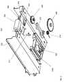
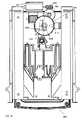
- FIG. 2illustrates an isometric front view of the HDD cartridge installed in the processor module
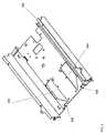
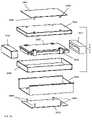
- FIG. 3illustrates an isometric exploded bottom view of the processor module subsystems and components and includes the HDD cartridge
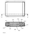
- FIG. 4illustrates an isometric rear view of the processor module showing the connectors
- FIG. 5illustrates an isometric bottom exploded view of an exemplary lockdown/eject subsystem
- FIG. 6illustrates an isometric top view of the HDD cartridge
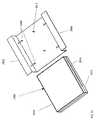
- FIG. 7illustrates an isometric exploded top view of the HDD cartridge
- FIG. 8illustrates an orthographic bottom view of the lockdown/eject subsystem
- FIG. 9illustrates an isometric top view of the lockdown-eject subsystem
- FIG. 10illustrates an isometric top view of an exemplary latch
- FIG. 11illustrates an isometric bottom view of the latch
- FIG. 12illustrates an isometric top view of an exemplary pusher
- FIG. 13illustrates an isometric bottom view of the pusher
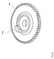
- FIG. 14illustrates an isometric top view of an exemplary spur gear
- FIG. 15illustrates an isometric view of HDD cartridge and pusher
- FIG. 16illustrates an isometric view of an exemplary chassis cover with locator pin
- FIG. 17illustrates an isometric view of an exemplary dampener
- FIG. 18illustrates an orthographic view of the lockdown/ejection subsystem in a first state
- FIG. 19illustrates an orthographic view of the lockdown/ejection subsystem and HDD cartridge in a second state
- FIG. 20illustrates a section view of HDD cartridge engaged with the pusher
- FIG. 21illustrates an orthographic view of the lockdown/ejection subsystem and HDD cartridge in a third state
- FIG. 22illustrates an orthographic view of the lockdown/ejection subsystem and HDD cartridge in a state of complete lockdown
- FIG. 23illustrates a block diagram of the electronic components in the ejection electronics subsystem
- FIG. 24illustrates an orthographic view of the lockdown/eject subsystem and HDD cartridge in a state during the process of ejection of the HDD cartridge
- FIG. 25illustrates an orthographic view of a lockdown/eject subsystem and HDD cartridge displaced
- FIG. 26illustrates an isometric exploded view of another exemplary system for locking down the HDD cartridge in a processor module
- FIG. 27illustrates an isometric view of an exemplary pin clip
- FIG. 28illustrates an orthographic section view of yet another exemplary system for locking down the HDD cartridge
- FIG. 29illustrates an isometric view of exemplary fixed pins
- FIG. 30illustrates an isometric exploded view of a lockdown subsystem using fixed pins
- FIG. 31illustrates an isometric view of the HDD slot plate.
- HDD-based media devicee.g., audio having a MP3 format
- a removable devicee.g., video content, map/navigation information, photos, etc.
- application of the inventionis not intended to be limited solely to media playback systems, for example it may be beneficially applied to HDD or other storage devices intended for the purposes of vehicle performance monitoring, data logging, delivery receipt storage and goods tracking, passenger statistic recording, etc.
- the followingdiscloses a mounting and protective system for fixedly mounting the HDD cartridge and processor module to an automobile while allowing for the selective removal of the HDD cartridge by a user.
- FIG. 1is a block diagram that illustrates how a hard disk drive-based media system is installed in an automobile.
- the installation of the current system and deviceis similar to installations of currently available multi-disk CD changers in automobiles.
- the HDD cartridge and processor module 100are mounted in the trunk in the example shown in FIG. 1 , but may be located in any convenient location on or within the automobile.
- a control bus 102for example an ACP system that is used in automobiles made by the Ford Motor Company, is used to send control messages from the head unit 104 to the processor module 100 .
- the processor moduledecodes digital media stored on the HDD 702 and converts the decompressed media into analog voltage fluctuations that are line level voltages, which are input into an automobile head unit 104 via a line level connection 106 .
- the head unittypically includes an amplifier to amplify the line level signal.
- the head unitalso includes a user interface for controlling the playback of the media. For example, a specific MP3 or other digital media file on HDD 702 may be selected and triggered to play back.
- the head unit user interfacetypically includes standard user interface functional control elements such as play, stop, pause, next track, last track, and the like, and also enables the user to browse or navigate through media files stored on HDD 702 .
- FIG. 2illustrates an isometric view of the HDD cartridge 200 inserted into the processor module 100 (also referred to as the “inserted state”).
- FIG. 3illustrates an exploded view of the processor module 100 , including processor printed circuit board (PCB) 300 which is located on top of lockdown/eject chassis 302 , and mounting plate 312 which serves to rigidly mount lockdown/eject chassis 302 .
- PCB 300includes the microprocessor 304 , microcontroller 306 , and other components that collectively function to process (i.e., decode) the content files that are stored on HDD 702 for playback by the system.
- Processor PCB 300also includes interface components that provide the functional electrical and signal interfaces to HDD 702 .
- Microprocessor 304also provides the logical processing of buttons and sensors related to the insertion and ejection of the HDD cartridge 200 .
- Mounting plate 312serves to attach the assembled system to the automobile.
- Top housing 202(not illustrated in FIG. 3 ) functions as a cosmetic and protective outer covering for processor module 100 .
- FIG. 4shows a rear view of processor module 100 .
- a system connector 402is provided which includes the line level audio outputs and ACP bus or other similar control interface.
- External USB connector(s) 404are also included for interfacing the HDD cartridge and processor module with external devices such as computers, other media playback devices, etc. It will be understood that other connections on and inside processor module 100 and HDD cartridge 200 may be provided for interfacing with other electronic devices. It will also be understood that in this and other Figures, connecting wires, flexible circuits, and other interconnect elements that functionally connect the electronic elements are not shown so as not to obscure the details of the present invention.
- a lockdown/eject subsystem 310 of the current embodimentis shown for providing both mechanical and electrical interface functionality when inserting and removing HDD cartridge 200 with respect to processor module 100 .
- the components of the lockdown/eject subsystem 310are fixedly mounted to the lockdown/eject chassis 302 .
- the lockdown/eject chassis 302may be fabricated out of bent sheetmetal, or any other suitably rigid material including but not limited to aluminum, iron, molded plastic, etc.
- the HDD cartridge 200is placed into the lockdown/eject chassis 302 during use in order to rigidly mount the HDD cartridge with respect to the frame of the automobile.
- the lockdown/eject chassis 302is screwed to a mounting plate 312 which serves to rigidly mount lockdown/eject chassis 302 to the automobile body via the mounting plate 312 , typically with the use of screws, bolts, rivets, or similar mounting elements through mounting holes 314 shown in FIG. 3 .
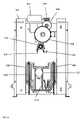
- FIG. 5 and FIG. 8show the lockdown/eject subsystem components of the current embodiment in greater detail.
- a DC motor 502 with a worm 504 attachedis mounted to the rear of lockdown/eject chassis 302 .
- the worm 504engages with step-down gear 506 , which in turn engages with spur gear 508 , such that when motor 502 is activated, spur gear 508 rotates but at a slower RPM than the motor.
- Step-down gear 506is mounted on a pivot rod (not shown) that is connected to lockdown/eject chassis 302
- the spur gearis mounted to a pivot rod (not shown) that is connected to mounting plate 312 .
- Latch 510pivots on a pivot rod 512 that is connected to lockdown/eject chassis 302 .
- a detector switch 514is mounted on a detector switch PCB 516 which is in turn fixedly mounted to lockdown/eject chassis 302 .
- FIG. 14which illustrates spur gear 508 in greater detail shows that spur gear 508 includes a latch actuator 1402 that depresses detector switch 514 at a specific point in the spur gear rotation.
- Latch actuator 1402 on spur gear 508also engages with the long edge of latch 510 and forces latch 510 to rotate at a specific point in the spur gear rotation.
- latch 510is forced to pivot clockwise by latch spring 518 .
- Latch spring 518is located on spring hub 1102 , shown in FIG. 11 .
- Latch spring 518is pre-loaded and bears against latch spring retainer 1104 on latch 510 , shown in FIG. 11 , and against spring stop 802 on lockdown/eject chassis 302 , shown in FIG. 8 .
- Locking pin 1002 (illustrated in FIG. 10 ) on latch 510protrudes substantially through locking pin aperture 520 on lockdown/eject chassis 302 , shown in FIG. 5 .
- right bevel 1202 and left bevel 1204 on pusher 1206protrude through pusher slots 902 , 904 on lockdown/eject chassis 302 .
- Pusher 1206slides along the length of pusher slots 902 , 904 .
- Pusher 1206is constrained in pusher slots 902 , 904 by lockdown/eject chassis 302 on the top surface and mounting plate 312 on the bottom surface.
- Pusher 1206is also forced toward the front of processor module 100 by left pusher spring 804 and right pusher spring 806 as shown in FIG. 8 .
- latch 510also includes a locking pin 1002 that resides at the same level as latch slot 1512 on the bottom rear area of HDD cartridge 200 .
- right bevel 1202 and left bevel 1204are fabricated to have opposing angled edges for purposes of guiding and rigidly fixing HDD cartridge 200 to processor module 100 during an insertion process, as described in greater detail below.
- chassis cover 316is screwed to the top of lockdown/eject chassis 302 .
- FIG. 16shows that chassis cover 316 includes a locator pin 1602 that is press fit or otherwise affixed into a hole in the rear vertical surface of chassis cover 316 .
- a dampener 522is located on the underside of pusher 1206 and is mounted with screws, bolts, or other fastening elements to mounting plate 312 as illustrated in FIG. 5 and FIG. 8 .
- FIG. 17further illustrates dampener 522 , which includes a dampener gear 1704 connected to an internal rotational velocity limiting apparatus 1702 . Dampener 522 is positioned so that dampener gear 1704 is engaged with dampener rack 1306 on the underside of pusher 1206 as illustrated in FIG. 8 .
- FIG. 7illustrates an exploded assembly view of the HDD cartridge 200 .
- the HDD 702is rigidly contained in an enclosure formed by the cartridge top housing 704 and cartridge bottom housing 706 , which are typically manufactured out of injection molded polycarbonate plastic.
- a cartridge PCB 708includes electronic components that provide the electrical and functional interface to the processor module 100 .
- Connectors 710 and 720are included on cartridge PCB 708 for connecting to the processor module and also for connecting to a PC or other computing device when the HDD cartridge is removed from the processor module.
- the cartridge top housing and cartridge bottom housingare fastened together with screws, bolts, or other similar fastening elements.
- top cushion 712 bottom front cushion 714 , right rear cushion 718 , and left rear cushion 716are injection molded out of a thermo-plastic elastomer (TPE) material, such as Santoprene, provided by Monsanto, Inc. of St. Louis, Mo.
- TPEthermo-plastic elastomer
- the durometer of the thermo-plastic elastomer of the described, exemplary embodimentis approximately SHORE A 50 .
- Top cushion 712 , bottom front cushion 714 , right rear cushion 716 , and left rear cushion 718may be attached to cartridge top housing 704 and cartridge bottom housing 706 respectively, by the technique of over-molding. For example, cartridge top housing 704 is placed into a injection mold with features to hold it in place, and the top cushion 712 is molded around it.
- the TPEis bonded directly to the surface of the polycarbonate, such that it is not easily removed.
- Over-moldingis a well-known process in the high volume plastics manufacturing. It will be understood and appreciated by those skilled in the art that various other resilient materials (e.g., elastomers, plastics, rubbers, etc.) may be used for the cushion elements as described above, and likewise different well known methods of molding and/or attaching such materials to the cartridge housing may be used without departing from the spirit and scope of the present invention.
- a right bevel cavity 1502 and left bevel cavity 1504are cavities that are molded into cartridge bottom housing 706 , located at the forward end of right pusher track 1508 and left pusher track 1506 respectively.
- Right bevel cavity 1502is shown in greater detail in FIG. 20 .
- the latch slot 1512is a cavity that is molded into cartridge bottom housing 706 , shown in FIG. 15 .
- FIG. 3shows that a locator hole 318 is molded into the rear-facing surface of cartridge top housing 704 .
- FIG. 2 and FIG. 7show than an eject button 204 which is included on the front face of HDD cartridge 200 , and is accessible by the user when HDD cartridge 200 is fully inserted into processor module 100 .
- Eject button 204is an injection-molded component that actuates an eject switch 2302 , which is a surface mount single throw single pole (STSP) switch, shown in the block diagram in FIG. 23 .
- STSPsurface mount single throw single pole
- FIG. 18is an orthographic bottom view of the lockdown/eject subsystem 310 with a portion of latch 510 , latch actuator 1402 on spur gear 508 , and detector switch 514 all shown in dashed lines because they are hidden in this view.
- Pusher 1206is forced to the front extent of its travel by left and right pusher springs 804 , 806 (hidden in this view).
- Latch 510is forced to the clockwise extent of its rotation by latch spring 518 .
- Latch 510is limited in its clockwise rotation by the contact of locking pin 1002 against the right side of locking pin aperture 520 (not shown in FIG. 18 for the purpose of clarity).
- the latch actuator mechanismis placed in a rotational position whereby it has depressed the detector switch 514 .
- FIG. 19shows state 2 where HDD cartridge 200 is placed into processor module 100 by the end user.
- locking pin 1002 on latch 510 and latch slot 1512 on cartridge bottom housing 706are shown as dashed lines because these features would normally be hidden in this view.
- Left and right pusher springs 804 , 806are hidden in the view of FIG. 19 , as well as other components that are not critical to explain the lockdown/eject subsystem.
- locking pin 1002 on latch 510begins to engage with latch slot 1512 on cartridge bottom housing 706 .
- the right and left pusher tracks 1508 , 1506 on the cartridge bottom housingalign with right and left bevels 1202 , 1204 respectively, on pusher 1206 .
- FIG. 20is a section view taken along axis A through HDD cartridge 200 that has been initially inserted into lockdown/eject subsystem 310 .
- right bevel 1202 and left bevel 1204engage with right bevel cavity 1502 and left bevel cavity 1504 .
- the action of the angled edge on right and left bevels 1202 , 1204 when in complete engagement with right and left bevel cavities 1502 , 1504rigidly fixes HDD cartridge 200 in lockdown/eject subsystem 310 .
- FIG. 21shows state 3 where HDD cartridge 200 is pushed further into processor module 100 by the user.
- spur gear 508is not shown in order to more clearly reveal the mechanism.
- Locking pin 1002is in contact with the right edge of latch slot 1512 .
- Latch 510is forced to rotate counter-clockwise as the locking pin rides down the angled right edge of latch slot 1512 .
- latch spring 518is compressed.
- Left and right pusher springs 804 , 806are elongated as pusher 1206 is displaced toward the rear of processor module 100 .
- FIG. 22shows state 4 where HDD cartridge 200 is locked into processor module 100 .
- spur gear 508is not shown for the purpose of clarity.
- latch spring 518forces the clockwise rotation of latch 510 such that latch pin 1002 is positioned behind a horizontal disposed portion of latch slot 1512 .
- the position of latch pin 1002 in this portion of latch slot 1512effectively locks HDD cartridge 200 inside processor module 100 such that HDD cartridge 200 will not become disengaged during use.
- FIG. 16shows that chassis cover includes a locator pin 1602 while FIG. 3 shows that cartridge top housing 704 includes a corresponding molded-in locator hole 318 .
- Locator pin 1602 and locator hole 318are aligned such that when HDD cartridge 200 is fully inserted into processor module 100 , locator pin 1602 is fully seated into locator hole 318 .
- HDD cartridge rotation about right and left bevels 1202 , 1204 , or any up or down or left or right displacement of the rear portion of HDD cartridge 200is generally prohibited.
- HDD cartridge 200may thus be constrained so that it cannot generally move with respect to processor module 100 as lockdown/eject subsystem 310 will hold HDD cartridge 200 rigidly to processor module 100 even in the presence of vibration and shock transferred from the motion of the automobile chassis. Accordingly, vibrations of the automobile's chassis are generally not amplified at the HDD when the automobile is driven.
- mode 1the system is functioning, performing digital media decoding or writing user inputs to the hard disk drive file system.
- mode 2the HDD 702 is spinning and its heads are reading from the disks and/or writing to the disks.
- mode 2the HDD 702 is not functioning and the HDD disks are not spinning.
- FIG. 18shows the position of spur gear 508 (shown in FIG. 18 , and that HDD cartridge 200 is fully inserted so that locking pin 1002 on latch 510 is located in latch slot 1512 as shown in FIG. 22 .
- the userwill activate the eject button 204 (shown in FIG. 6 ).
- FIG. 23shows the general electronic components that are combined to make the ejection electronics subsystem.
- Microprocessor 304handles media decoding and user input processing.
- Microcontroller 306handles inputs from eject switch 2302 (actuated by eject button 204 ) and detector switch 514 , and controls motor 502 and status LEDs 602 .
- the general sequence of events that occur when eject button is activated by the useris as follows:
- Microcontroller 306signals to microprocessor 304 that ejection has been activated.
- Microprocessor 304completes processing activity including writing to HDD 702 if necessary.
- Microprocessor 304turns off power to HDD 702 .
- Microprocessor 304signals to microcontroller 302 that HDD cartridge 200 is ready for ejection.
- Microcontroller 306activates power to motor 502 through one transition of the detector switch 514 from activated to deactivated.
- Microcontroller 306deactivates power to motor 502 upon transition of detector switch 514 from deactivated to activated.
- the motor 502is illustrated in an activated state.
- the gear-train of worm 504engages with step-down gear 506 which in turn engages with spur gear 508 , causing spur gear 508 to rotate clockwise (with respect to the view shown in FIG. 24 ).
- Latch actuator 1402rotates away from detector switch 514 , thus detector switch 514 transitions from an activated state to a deactivated state.
- Latch actuator 1402 on spur gear 508also comes into contact with the right edge of latch 510 .
- latch 510is driven to rotate counter-clockwise with respect to the view shown in FIG. 24 .
- locking pin 1002moves left in latch cavity 1502 .
- FIG. 24locking pin 1002 on latch 510 has moved to the edge of the horizontal bottom surface of latch slot 1512 .
- latch 510has continued to rotate counter-clockwise and locking pin 1002 has moved further to the left.
- Locking pin 1002engages with the angled surface on latch slot 1512 on cartridge bottom housing 706 , forcing HDD cartridge 200 forward with respect to the processor module 100 .
- This leveraged forceovercomes any binding that may have occurred between HDD cartridge 200 , pusher 1206 , and lockdown chassis 302 .
- right and left pusher springs 806 , 804force pusher 1206 and HDD cartridge 200 toward the front of processor module 100 .
- FIG. 5 and FIG. 8show dampener 522 that limits the ejection velocity of pusher 1206 during the ejection process.
- the ejection process for mode 2will now be described.
- the ejection mechanism stateis the same as that which is described above for mode 1.
- the general sequence of events that occur when eject button 204 is activated by the useris as follows:
- Microcontroller 306signals to microprocessor 304 that ejection has been activated.
- Microprocessor 304signals to microcontroller 302 that HDD cartridge 200 is ready for ejection.
- Microcontroller 306activates power to motor 502 through one transition of the detector switch 514 from activated to deactivated.
- Microcontroller 306deactivates power to motor 502 upon transition of detector switch 514 from deactivated to activated.
- HDD 702 inside HDD cartridge 200will experience reduced shock loads when dropped onto a firm surface because top cushion 712 , bottom front cushion 714 , right rear cushion 718 , and left rear cushion 716 will absorb energy during impact. Because of the location of the elastomeric material, HDD 702 is protected when dropped on any of four corners or on any of six sides.
- front cushion 714 , right rear cushion 718 , and left rear cushion 716are configured about cartridge bottom housing 706 such that portions of cartridge bottom housing 706 (i.e., latch slot 1512 , right bevel cavity 1502 , left bevel cavity 1504 , right pusher slot 1506 , and left pusher slot 1508 ) which are operative with corresponding components of processor module 100 for purposes of rigidly mounting HDD cartridge 200 to processor module 100 are exposed, while still providing a protective function with respect to the underside surface and corners of HDD cartridge 200 .
- portions of cartridge bottom housing 706i.e., latch slot 1512 , right bevel cavity 1502 , left bevel cavity 1504 , right pusher slot 1506 , and left pusher slot 1508 .
- HDD cartridge 200different configurations of elastomeric materials about HDD cartridge 200 are possible, including substantially enclosing all of HDD cartridge 200 in an elastomeric or similar cushioning material, while still providing for the rigid mounting of HDD cartridge 200 with respect to processor module 100 in accordance with the teachings detailed herein.
- FIG. 26is an isometric exploded view of an exemplary system wherein the cushions 2610 , 2612 that protect the hard disk drive 2602 from high shock loads are located inside of the plastic housing 2604 , 2606 that surrounds the hard disk drive 2602 .
- the HDD cartridge 2600also includes four holes in the top housing 2604 and four holes in the bottom housing 2606 that receive metal pins 2608 when the HDD cartridge 2600 is in the lockdown position.
- FIG. 28shows a sectional view along axis A through a HDD cartridge 2600 and a lockdown subsystem where the cushion is able to be located inside the HDD cartridge housing.
- the HDD cartridge 2600When the HDD cartridge 2600 has been inserted fully into the processor module it is aligned by the chassis 2616 .
- a top pin plate 2620 and bottom pin plate 2618are displaced toward the HDD cartridge 2600 .
- the top pin plate 2620 and the bottom pin plate 2618each include four pins 2608 that align with the holes in the top housing 2604 and bottom housing 2606 , respectively.
- the top pin plate 2620 and bottom pin plate 2618are driven toward the HDD cartridge 2600 by a motorized mechanism (not shown)
- Four pin clips 2614are attached to the HDD 2602 as shown in FIG. 26 .
- FIG. 27A single pin clip 2614 is shown in FIG. 27 , and is fabricated out of bent sheet metal.
- the pin clipsboth take the axial load of the pin 2608 against the HDD 2602 , and also keep the HDD 2602 from moving laterally in any direction because each pin 2608 fits into a corresponding pin hole 2702 located on the top and bottom of each pin clip 2614 .
- FIG. 28shows four of the pins 2608 engaged in the top and bottom of two of the pin clips 2614 .
- HDDis generally protected from shock loads from dropping in this embodiment by the internal cushions, which absorb the energy from the shock loads. It will be appreciated that it is well within the routine abilities of one skilled in the art to implement the various components and elements (including an appropriate motorized mechanism) given the inventive teachings described herein.
- FIG. 29shows a fixed pin HDD cartridge 2900 and a fixed pin alignment chassis 2902 as a further exemplary system.
- This systemuses a number of fixed metal pins 2904 protruding from the alignment chassis 2906 to constrain fixed pin HDD cartridge 2900 when inserted into the processor module.
- FIG. 30shows an exploded view of the fixed pin HDD cartridge 2900 alongside the fixed pin alignment chassis 2902 .
- a HDD slot plate 3002fabricated out of sheet metal, is attached to HDD 3004 .
- FIG. 31shows that HDD slot plate 3002 includes two side slots 3102 , 3104 and a bottom slot 3106 . Attachment holes 3108 in the bottom are used to screw the HDD slot plate 3002 to the HDD 3004 .
- a bottom housing 3006 and a top housing 3008are attached to HDD 3004 .
- Both bottom housing 3006 and top housing 3008are made out of injection molded plastic, and include slots in the sides.
- the bottom housingincludes a bottom slot 3010 .
- the slots on bottom and top housings 3006 , 3008align with the slots on the HDD slot plate 3002 .
- a bottom cushion 3012 and a top cushion 3014are attached to bottom housing 3006 and top housing 3008 respectively, through the process of insert injection molding. Therefore, top and bottom cushions 3014 , 3012 are securely attached to top and bottom housings 3008 , 3006 .
- Top cushion 3014 and bottom cushion 3012also include slots 2910 in the side to provide clearance for pins.
- Bottom cushion 3012also includes a bottom slot 3018 to provide clearance for bottom pins. The slots in the bottom and top cushions 3012 , 3014 are aligned with the slots on HDD slot plate 3002 .
- the side pins 2904 and bottom pins 2912align with the slots 2910 , 3018 , 3010 , 3102 , 3104 , 3106 present in the various components of the fixed pin HDD cartridge assembly 2900 .
- the slots 3102 in HDD slot plate 3002are slightly larger than the diameter of the pins 2904 in fixed pin alignment chassis 2902 .
- the openings of the slots 3102 , 3104 , 3106 in HDD slot plate 3002are slightly tapered, so initial engagement of the slots with the pins 2904 , 2912 is easily accomplished.
- the slots 2910 , 3010 , 3018 in the other componentsare clearance slots so their dimension is slightly larger than the slots 3102 , 3104 , 3106 in the HDD slot plate 3002 .
- a motorized mechanismis used to lock the fixed pin HDD cartridge 2900 in the processor module once it is fully inserted.
- fixed pin HDD cartridge 2900When fixed pin HDD cartridge 2900 is fully inserted into processor module, fixed pin HDD cartridge 2900 is constrained and it cannot generally move with respect to processor module. Therefore, vibrations of the automobile's chassis are generally not amplified at the HDD 3004 . It will also be appreciated that it is well within the routine abilities of one skilled in the art to implement the various components and elements (including an appropriate motorized mechanism) given the inventive teachings described herein.
Landscapes
- Engineering & Computer Science (AREA)
- Theoretical Computer Science (AREA)
- Computer Hardware Design (AREA)
- Power Engineering (AREA)
- Human Computer Interaction (AREA)
- Physics & Mathematics (AREA)
- General Engineering & Computer Science (AREA)
- General Physics & Mathematics (AREA)
- Multimedia (AREA)
- Mechanical Engineering (AREA)
- Feeding And Guiding Record Carriers (AREA)
Abstract
Description
Claims (9)
Priority Applications (2)
| Application Number | Priority Date | Filing Date | Title |
|---|---|---|---|
| US11/018,297US7652844B2 (en) | 2003-12-24 | 2004-12-21 | System and method for protecting removeable media playback devices |
| US12/606,386US8184400B2 (en) | 2003-12-24 | 2009-10-27 | System and method for protecting removeable media playback devices |
Applications Claiming Priority (2)
| Application Number | Priority Date | Filing Date | Title |
|---|---|---|---|
| US53205603P | 2003-12-24 | 2003-12-24 | |
| US11/018,297US7652844B2 (en) | 2003-12-24 | 2004-12-21 | System and method for protecting removeable media playback devices |
Related Child Applications (1)
| Application Number | Title | Priority Date | Filing Date |
|---|---|---|---|
| US12/606,386ContinuationUS8184400B2 (en) | 2003-12-24 | 2009-10-27 | System and method for protecting removeable media playback devices |
Publications (2)
| Publication Number | Publication Date |
|---|---|
| US20050183104A1 US20050183104A1 (en) | 2005-08-18 |
| US7652844B2true US7652844B2 (en) | 2010-01-26 |
Family
ID=34840376
Family Applications (2)
| Application Number | Title | Priority Date | Filing Date |
|---|---|---|---|
| US11/018,297Active2026-03-03US7652844B2 (en) | 2003-12-24 | 2004-12-21 | System and method for protecting removeable media playback devices |
| US12/606,386Expired - LifetimeUS8184400B2 (en) | 2003-12-24 | 2009-10-27 | System and method for protecting removeable media playback devices |
Family Applications After (1)
| Application Number | Title | Priority Date | Filing Date |
|---|---|---|---|
| US12/606,386Expired - LifetimeUS8184400B2 (en) | 2003-12-24 | 2009-10-27 | System and method for protecting removeable media playback devices |
Country Status (1)
| Country | Link |
|---|---|
| US (2) | US7652844B2 (en) |
Cited By (8)
| Publication number | Priority date | Publication date | Assignee | Title |
|---|---|---|---|---|
| US8028323B2 (en) | 2004-05-05 | 2011-09-27 | Dryden Enterprises, Llc | Method and system for employing a first device to direct a networked audio device to obtain a media item |
| US8028038B2 (en) | 2004-05-05 | 2011-09-27 | Dryden Enterprises, Llc | Obtaining a playlist based on user profile matching |
| US8045952B2 (en) | 1998-01-22 | 2011-10-25 | Horsham Enterprises, Llc | Method and device for obtaining playlist content over a network |
| US8508401B1 (en) | 2010-08-31 | 2013-08-13 | Logitech Europe S.A. | Delay fixing for command codes in a remote control system |
| US8725740B2 (en) | 2008-03-24 | 2014-05-13 | Napo Enterprises, Llc | Active playlist having dynamic media item groups |
| US8797149B2 (en) | 2000-03-15 | 2014-08-05 | Logitech Europe S.A. | State-based control systems and methods |
| US9178946B2 (en) | 2004-05-05 | 2015-11-03 | Black Hills Media, Llc | Device discovery for digital entertainment network |
| US9207652B2 (en) | 2005-04-20 | 2015-12-08 | Logitech Europe S.A. | System and method for adaptive programming of a remote control |
Families Citing this family (10)
| Publication number | Priority date | Publication date | Assignee | Title |
|---|---|---|---|---|
| US20010033243A1 (en) | 2000-03-15 | 2001-10-25 | Harris Glen Mclean | Online remote control configuration system |
| US6784805B2 (en) | 2000-03-15 | 2004-08-31 | Intrigue Technologies Inc. | State-based remote control system |
| US7885622B2 (en) | 2004-10-27 | 2011-02-08 | Chestnut Hill Sound Inc. | Entertainment system with bandless tuning |
| US20190278560A1 (en) | 2004-10-27 | 2019-09-12 | Chestnut Hill Sound, Inc. | Media appliance with auxiliary source module docking and fail-safe alarm modes |
| US8090309B2 (en) | 2004-10-27 | 2012-01-03 | Chestnut Hill Sound, Inc. | Entertainment system with unified content selection |
| US7612994B2 (en)* | 2006-10-31 | 2009-11-03 | Prostor Systems, Inc. | Hard drive cartridge protection |
| US8918544B2 (en) | 2011-03-31 | 2014-12-23 | Logitech Europe S.A. | Apparatus and method for configuration and operation of a remote-control system |
| US9239837B2 (en) | 2011-04-29 | 2016-01-19 | Logitech Europe S.A. | Remote control system for connected devices |
| WO2022095079A1 (en)* | 2020-11-05 | 2022-05-12 | 苏州市英酷莱德信息科技有限公司 | Protective structure for solid-state drive |
| CN119218114B (en)* | 2024-09-25 | 2025-05-13 | 深圳市新正虹塑胶电子有限公司 | Automobile radar probe with protection structure |
Citations (40)
| Publication number | Priority date | Publication date | Assignee | Title |
|---|---|---|---|---|
| US5043974A (en)* | 1988-09-26 | 1991-08-27 | Sony Corporation | Disc cartridge |
| US5084861A (en)* | 1987-09-24 | 1992-01-28 | Sony Corporation | Disc cartridge having molded disk support elements attached by rigid legs |
| US5214550A (en) | 1991-03-22 | 1993-05-25 | Zentek Storage Of America, Inc. | Miniature removable rigid disk drive and cartridge system |
| US5434860A (en) | 1994-04-20 | 1995-07-18 | Apple Computer, Inc. | Flow control for real-time data streams |
| US5526337A (en)* | 1994-06-30 | 1996-06-11 | Tamarack Storage Devices | Holographic storage media package |
| US5721827A (en) | 1996-10-02 | 1998-02-24 | James Logan | System for electrically distributing personalized information |
| US5724567A (en) | 1994-04-25 | 1998-03-03 | Apple Computer, Inc. | System for directing relevance-ranked data objects to computer users |
| US5742599A (en) | 1996-02-26 | 1998-04-21 | Apple Computer, Inc. | Method and system for supporting constant bit rate encoded MPEG-2 transport over local ATM networks |
| US5758257A (en) | 1994-11-29 | 1998-05-26 | Herz; Frederick | System and method for scheduling broadcast of and access to video programs and other data using customer profiles |
| US5790935A (en) | 1996-01-30 | 1998-08-04 | Hughes Aircraft Company | Virtual on-demand digital information delivery system and method |
| US5793980A (en) | 1994-11-30 | 1998-08-11 | Realnetworks, Inc. | Audio-on-demand communication system |
| JPH10261254A (en)* | 1997-03-18 | 1998-09-29 | Mitsubishi Electric Corp | Disk exchange device |
| US5884028A (en) | 1994-07-29 | 1999-03-16 | International Business Machines Corporation | System for the management of multiple time-critical data streams |
| WO1999018506A1 (en) | 1997-10-03 | 1999-04-15 | Audible, Inc. | Method and apparatus for targeting a digital information playback device |
| US5926624A (en) | 1996-09-12 | 1999-07-20 | Audible, Inc. | Digital information library and delivery system with logic for generating files targeted to the playback device |
| US5991306A (en) | 1996-08-26 | 1999-11-23 | Microsoft Corporation | Pull based, intelligent caching system and method for delivering data over a network |
| US6005566A (en) | 1994-05-19 | 1999-12-21 | Apple Computer, Inc. | Aspect and style elements of an improved graphical user interface |
| EP0992921A2 (en) | 1998-09-29 | 2000-04-12 | Lucent Technologies Inc. | Computer access dependent on the location of the accessing terminal |
| WO2000023899A1 (en) | 1998-10-16 | 2000-04-27 | Safi Qureshey | Remote audio computer peripheral device |
| WO2000049731A1 (en) | 1999-02-19 | 2000-08-24 | Bodycom, Inc. | Personal digital assistant with wireless telephone |
| WO2001010124A1 (en) | 1999-08-02 | 2001-02-08 | Sun Microsystems, Inc. | Method and apparatus for presenting video data obtained from a network |
| WO2001047192A1 (en) | 1999-12-21 | 2001-06-28 | Intel Corporation | A dedicated digital-to-analog network audio bridging method and system |
| US6263503B1 (en) | 1999-05-26 | 2001-07-17 | Neal Margulis | Method for effectively implementing a wireless television system |
| US6271989B1 (en)* | 1997-09-15 | 2001-08-07 | Hans K. Tannert | Method for inserting a removable disk cartridge into a disk drive |
| US6324054B1 (en)* | 1998-01-26 | 2001-11-27 | Seagate Technology Llc | Wrap around shock absorber for disc drives |
| US20020056112A1 (en) | 1999-06-03 | 2002-05-09 | Vincent Dureau | Home digital assistant |
| US6434747B1 (en) | 2000-01-19 | 2002-08-13 | Individual Network, Inc. | Method and system for providing a customized media list |
| US6453355B1 (en) | 1998-01-15 | 2002-09-17 | Apple Computer, Inc. | Method and apparatus for media data transmission |
| US6491194B2 (en) | 2001-01-29 | 2002-12-10 | Ernest Marvin | Cell phone holder for motor vehicles |
| US6526581B1 (en) | 1999-08-03 | 2003-02-25 | Ucentric Holdings, Llc | Multi-service in-home network with an open interface |
| US6614751B1 (en)* | 1999-03-18 | 2003-09-02 | Hisashi Katao | Disk cartridge, optical disk drive, optical library and optical storage system |
| EP0909112B1 (en) | 1997-09-26 | 2004-01-07 | Touchtunes Music Corporation | Wireless system with digital transmission for loudspeakers |
| US6678737B1 (en) | 2000-04-28 | 2004-01-13 | Webtv Networks, Inc. | Home network appliance and method |
| US6678215B1 (en) | 1999-12-28 | 2004-01-13 | G. Victor Treyz | Digital audio devices |
| US6700893B1 (en) | 1999-11-15 | 2004-03-02 | Koninklijke Philips Electronics N.V. | System and method for controlling the delay budget of a decoder buffer in a streaming data receiver |
| US6708213B1 (en) | 1999-12-06 | 2004-03-16 | Lucent Technologies Inc. | Method for streaming multimedia information over public networks |
| US6717952B2 (en) | 1998-01-15 | 2004-04-06 | Apple Computer, Inc. | Method and apparatus for media data transmission |
| US6744763B1 (en) | 1998-01-15 | 2004-06-01 | Apple Computer, Inc. | Method and apparatus for media data transmission |
| US6826283B1 (en) | 2000-07-27 | 2004-11-30 | 3Com Corporation | Method and system for allowing multiple nodes in a small environment to play audio signals independent of other nodes |
| US7191242B1 (en) | 2000-06-22 | 2007-03-13 | Apple, Inc. | Methods and apparatuses for transferring data |
Family Cites Families (3)
| Publication number | Priority date | Publication date | Assignee | Title |
|---|---|---|---|---|
| US5149048A (en)* | 1990-12-19 | 1992-09-22 | Integral Peripherals | Shock absorbent mounting arrangement for disk drive or other component |
| US5084864A (en)* | 1990-05-14 | 1992-01-28 | The Boeing Company | Broadband, inductively coupled, duplex, rf transmission system |
| JP2002015553A (en)* | 2000-06-16 | 2002-01-18 | Internatl Business Mach Corp <Ibm> | Plate-like appliance, appliance with built-in rotating body and disk device |
- 2004
- 2004-12-21USUS11/018,297patent/US7652844B2/enactiveActive
- 2009
- 2009-10-27USUS12/606,386patent/US8184400B2/ennot_activeExpired - Lifetime
Patent Citations (43)
| Publication number | Priority date | Publication date | Assignee | Title |
|---|---|---|---|---|
| US5084861A (en)* | 1987-09-24 | 1992-01-28 | Sony Corporation | Disc cartridge having molded disk support elements attached by rigid legs |
| US5043974A (en)* | 1988-09-26 | 1991-08-27 | Sony Corporation | Disc cartridge |
| US5214550A (en) | 1991-03-22 | 1993-05-25 | Zentek Storage Of America, Inc. | Miniature removable rigid disk drive and cartridge system |
| US5434860A (en) | 1994-04-20 | 1995-07-18 | Apple Computer, Inc. | Flow control for real-time data streams |
| US5724567A (en) | 1994-04-25 | 1998-03-03 | Apple Computer, Inc. | System for directing relevance-ranked data objects to computer users |
| US6005566A (en) | 1994-05-19 | 1999-12-21 | Apple Computer, Inc. | Aspect and style elements of an improved graphical user interface |
| US5526337A (en)* | 1994-06-30 | 1996-06-11 | Tamarack Storage Devices | Holographic storage media package |
| US5884028A (en) | 1994-07-29 | 1999-03-16 | International Business Machines Corporation | System for the management of multiple time-critical data streams |
| US5758257A (en) | 1994-11-29 | 1998-05-26 | Herz; Frederick | System and method for scheduling broadcast of and access to video programs and other data using customer profiles |
| US5793980A (en) | 1994-11-30 | 1998-08-11 | Realnetworks, Inc. | Audio-on-demand communication system |
| US5790935A (en) | 1996-01-30 | 1998-08-04 | Hughes Aircraft Company | Virtual on-demand digital information delivery system and method |
| US5742599A (en) | 1996-02-26 | 1998-04-21 | Apple Computer, Inc. | Method and system for supporting constant bit rate encoded MPEG-2 transport over local ATM networks |
| US5991306A (en) | 1996-08-26 | 1999-11-23 | Microsoft Corporation | Pull based, intelligent caching system and method for delivering data over a network |
| US5926624A (en) | 1996-09-12 | 1999-07-20 | Audible, Inc. | Digital information library and delivery system with logic for generating files targeted to the playback device |
| US5721827A (en) | 1996-10-02 | 1998-02-24 | James Logan | System for electrically distributing personalized information |
| JPH10261254A (en)* | 1997-03-18 | 1998-09-29 | Mitsubishi Electric Corp | Disk exchange device |
| US6271989B1 (en)* | 1997-09-15 | 2001-08-07 | Hans K. Tannert | Method for inserting a removable disk cartridge into a disk drive |
| EP0909112B1 (en) | 1997-09-26 | 2004-01-07 | Touchtunes Music Corporation | Wireless system with digital transmission for loudspeakers |
| WO1999018506A1 (en) | 1997-10-03 | 1999-04-15 | Audible, Inc. | Method and apparatus for targeting a digital information playback device |
| US7366788B2 (en) | 1998-01-15 | 2008-04-29 | Apple Inc. | Method and apparatus for media data transmission |
| US6829648B1 (en) | 1998-01-15 | 2004-12-07 | Apple Computer, Inc. | Method and apparatus for preparing media data for transmission |
| US6744763B1 (en) | 1998-01-15 | 2004-06-01 | Apple Computer, Inc. | Method and apparatus for media data transmission |
| US6717952B2 (en) | 1998-01-15 | 2004-04-06 | Apple Computer, Inc. | Method and apparatus for media data transmission |
| US6453355B1 (en) | 1998-01-15 | 2002-09-17 | Apple Computer, Inc. | Method and apparatus for media data transmission |
| US6324054B1 (en)* | 1998-01-26 | 2001-11-27 | Seagate Technology Llc | Wrap around shock absorber for disc drives |
| EP0992921A2 (en) | 1998-09-29 | 2000-04-12 | Lucent Technologies Inc. | Computer access dependent on the location of the accessing terminal |
| WO2000023899A1 (en) | 1998-10-16 | 2000-04-27 | Safi Qureshey | Remote audio computer peripheral device |
| WO2000049731A1 (en) | 1999-02-19 | 2000-08-24 | Bodycom, Inc. | Personal digital assistant with wireless telephone |
| US6614751B1 (en)* | 1999-03-18 | 2003-09-02 | Hisashi Katao | Disk cartridge, optical disk drive, optical library and optical storage system |
| US6263503B1 (en) | 1999-05-26 | 2001-07-17 | Neal Margulis | Method for effectively implementing a wireless television system |
| US20020056112A1 (en) | 1999-06-03 | 2002-05-09 | Vincent Dureau | Home digital assistant |
| WO2001010124A1 (en) | 1999-08-02 | 2001-02-08 | Sun Microsystems, Inc. | Method and apparatus for presenting video data obtained from a network |
| US6526581B1 (en) | 1999-08-03 | 2003-02-25 | Ucentric Holdings, Llc | Multi-service in-home network with an open interface |
| US6700893B1 (en) | 1999-11-15 | 2004-03-02 | Koninklijke Philips Electronics N.V. | System and method for controlling the delay budget of a decoder buffer in a streaming data receiver |
| US6708213B1 (en) | 1999-12-06 | 2004-03-16 | Lucent Technologies Inc. | Method for streaming multimedia information over public networks |
| WO2001047192A1 (en) | 1999-12-21 | 2001-06-28 | Intel Corporation | A dedicated digital-to-analog network audio bridging method and system |
| US6678215B1 (en) | 1999-12-28 | 2004-01-13 | G. Victor Treyz | Digital audio devices |
| US6434747B1 (en) | 2000-01-19 | 2002-08-13 | Individual Network, Inc. | Method and system for providing a customized media list |
| US7117516B2 (en) | 2000-01-19 | 2006-10-03 | Individual Networks Llc | Method and system for providing a customized media list |
| US6678737B1 (en) | 2000-04-28 | 2004-01-13 | Webtv Networks, Inc. | Home network appliance and method |
| US7191242B1 (en) | 2000-06-22 | 2007-03-13 | Apple, Inc. | Methods and apparatuses for transferring data |
| US6826283B1 (en) | 2000-07-27 | 2004-11-30 | 3Com Corporation | Method and system for allowing multiple nodes in a small environment to play audio signals independent of other nodes |
| US6491194B2 (en) | 2001-01-29 | 2002-12-10 | Ernest Marvin | Cell phone holder for motor vehicles |
Non-Patent Citations (3)
| Title |
|---|
| G. Degoulet et al., EPEOS-Automatic Program Recording System, Nov. 1975, 22 pgs. |
| PR Newswire, New Company Xenote Allows Consumers to 'Bookmark the Real World' with Fun, Personal Internet Device, Jan. 25, 2000, 2pgs. |
| Tivo, Inc., Form S-1, Jul. 22, 1999, 902 pgs. |
Cited By (19)
| Publication number | Priority date | Publication date | Assignee | Title |
|---|---|---|---|---|
| US8755763B2 (en) | 1998-01-22 | 2014-06-17 | Black Hills Media | Method and device for an internet radio capable of obtaining playlist content from a content server |
| US9397627B2 (en) | 1998-01-22 | 2016-07-19 | Black Hills Media, Llc | Network-enabled audio device |
| US8045952B2 (en) | 1998-01-22 | 2011-10-25 | Horsham Enterprises, Llc | Method and device for obtaining playlist content over a network |
| US8050652B2 (en) | 1998-01-22 | 2011-11-01 | Horsham Enterprises, Llc | Method and device for an internet radio capable of obtaining playlist content from a content server |
| US8918480B2 (en) | 1998-01-22 | 2014-12-23 | Black Hills Media, Llc | Method, system, and device for the distribution of internet radio content |
| US8792850B2 (en) | 1998-01-22 | 2014-07-29 | Black Hills Media | Method and device for obtaining playlist content over a network |
| US8797149B2 (en) | 2000-03-15 | 2014-08-05 | Logitech Europe S.A. | State-based control systems and methods |
| US8230099B2 (en) | 2004-05-05 | 2012-07-24 | Dryden Enterprises, Llc | System and method for sharing playlists |
| US8458356B2 (en) | 2004-05-05 | 2013-06-04 | Black Hills Media | System and method for sharing playlists |
| US8028323B2 (en) | 2004-05-05 | 2011-09-27 | Dryden Enterprises, Llc | Method and system for employing a first device to direct a networked audio device to obtain a media item |
| US9178946B2 (en) | 2004-05-05 | 2015-11-03 | Black Hills Media, Llc | Device discovery for digital entertainment network |
| US8028038B2 (en) | 2004-05-05 | 2011-09-27 | Dryden Enterprises, Llc | Obtaining a playlist based on user profile matching |
| US9516370B1 (en) | 2004-05-05 | 2016-12-06 | Black Hills Media, Llc | Method, device, and system for directing a wireless speaker from a mobile phone to receive and render a playlist from a content server on the internet |
| US9554405B2 (en) | 2004-05-05 | 2017-01-24 | Black Hills Media, Llc | Wireless speaker for receiving from a mobile phone directions to receive and render a playlist from a content server on the internet |
| US9584591B1 (en) | 2004-05-05 | 2017-02-28 | Black Hills Media, Llc | Method and device for sharing a playlist at a dedicated media player device |
| US9826046B2 (en) | 2004-05-05 | 2017-11-21 | Black Hills Media, Llc | Device discovery for digital entertainment network |
| US9207652B2 (en) | 2005-04-20 | 2015-12-08 | Logitech Europe S.A. | System and method for adaptive programming of a remote control |
| US8725740B2 (en) | 2008-03-24 | 2014-05-13 | Napo Enterprises, Llc | Active playlist having dynamic media item groups |
| US8508401B1 (en) | 2010-08-31 | 2013-08-13 | Logitech Europe S.A. | Delay fixing for command codes in a remote control system |
Also Published As
| Publication number | Publication date |
|---|---|
| US8184400B2 (en) | 2012-05-22 |
| US20100046113A1 (en) | 2010-02-25 |
| US20050183104A1 (en) | 2005-08-18 |
Similar Documents
| Publication | Publication Date | Title |
|---|---|---|
| US8184400B2 (en) | System and method for protecting removeable media playback devices | |
| JP4944528B2 (en) | Buffer member | |
| US7386868B2 (en) | External desktop dock for a cartridge-based data storage unit | |
| US5065262A (en) | Removable and transportable hard disk subsystem | |
| CN1033939C (en) | Shockproof Portable Disk Storage Unit | |
| US7134128B2 (en) | Disk drive with protection from static electricity | |
| US6195225B1 (en) | Disk drive having anti-wobbling mechanism | |
| US6147596A (en) | Vehicle-mounted record medium reproducing apparatus | |
| US20070133122A1 (en) | Hard disk drive | |
| WO2002023886A1 (en) | Portable digital imaging device | |
| US6947355B2 (en) | Optical disk drive having function of removing static electricity of optical disk | |
| US20040062171A1 (en) | Locking mechanism of external optical disk drive | |
| JP2008189031A (en) | On-vehicle electronic equipment | |
| US20140112638A1 (en) | Dual stage hybrid drive | |
| CN101154411A (en) | CD device | |
| US20030152011A1 (en) | Vibration absorbing mechanism for an optical disk drive | |
| CN105593939B (en) | Storage device | |
| US7120919B2 (en) | Disk holding device for optical disk reading device | |
| US7637755B2 (en) | Data protecting apparatus and data protecting method | |
| JP3885635B2 (en) | Disk unit | |
| JP2818257B2 (en) | Drive device for optical memory | |
| CN219610020U (en) | Hard disk damping device | |
| JPH1139760A (en) | Disk device | |
| US7379396B2 (en) | Rotary disk type storage device | |
| CN100441075C (en) | Panel mount equipment for vehicle audio systems |
Legal Events
| Date | Code | Title | Description |
|---|---|---|---|
| AS | Assignment | Owner name:UNIVERSAL ELECTRONICS INC., CALIFORNIA Free format text:ASSIGNMENT OF ASSIGNORS INTEREST;ASSIGNORS:EDWARDS, BRUCE;KALAYJIAN, NICK;JANIK, CRAIG;REEL/FRAME:016114/0889 Effective date:20041220 | |
| AS | Assignment | Owner name:EZ4MEDIA, INC., ILLINOIS Free format text:ASSIGNMENT OF ASSIGNORS INTEREST;ASSIGNOR:UNIVERSAL ELECTRONICS INC.;REEL/FRAME:020845/0386 Effective date:20080331 Owner name:EZ4MEDIA, INC.,ILLINOIS Free format text:ASSIGNMENT OF ASSIGNORS INTEREST;ASSIGNOR:UNIVERSAL ELECTRONICS INC.;REEL/FRAME:020845/0386 Effective date:20080331 | |
| AS | Assignment | Owner name:VIVIANA RESEARCH LLC, DELAWARE Free format text:ASSIGNMENT OF ASSIGNORS INTEREST;ASSIGNOR:EZ4MEDIA, INC.;REEL/FRAME:022528/0112 Effective date:20090331 | |
| FEPP | Fee payment procedure | Free format text:PAYOR NUMBER ASSIGNED (ORIGINAL EVENT CODE: ASPN); ENTITY STATUS OF PATENT OWNER: LARGE ENTITY | |
| STCF | Information on status: patent grant | Free format text:PATENTED CASE | |
| CC | Certificate of correction | ||
| FPAY | Fee payment | Year of fee payment:4 | |
| AS | Assignment | Owner name:CALLAHAN CELLULAR L.L.C., DELAWARE Free format text:MERGER;ASSIGNOR:VIVIANA RESEARCH LLC;REEL/FRAME:036966/0283 Effective date:20150827 | |
| FPAY | Fee payment | Year of fee payment:8 | |
| MAFP | Maintenance fee payment | Free format text:PAYMENT OF MAINTENANCE FEE, 12TH YEAR, LARGE ENTITY (ORIGINAL EVENT CODE: M1553); ENTITY STATUS OF PATENT OWNER: LARGE ENTITY Year of fee payment:12 |