US7651513B2 - Flexible embolic device delivery system - Google Patents
Flexible embolic device delivery systemDownload PDFInfo
- Publication number
- US7651513B2 US7651513B2US10/407,295US40729503AUS7651513B2US 7651513 B2US7651513 B2US 7651513B2US 40729503 AUS40729503 AUS 40729503AUS 7651513 B2US7651513 B2US 7651513B2
- Authority
- US
- United States
- Prior art keywords
- conductive substance
- wire
- distal end
- segment
- conductive
- Prior art date
- Legal status (The legal status is an assumption and is not a legal conclusion. Google has not performed a legal analysis and makes no representation as to the accuracy of the status listed.)
- Active, expires
Links
Images

Classifications
- A—HUMAN NECESSITIES
- A61—MEDICAL OR VETERINARY SCIENCE; HYGIENE
- A61B—DIAGNOSIS; SURGERY; IDENTIFICATION
- A61B17/00—Surgical instruments, devices or methods
- A61B17/12—Surgical instruments, devices or methods for ligaturing or otherwise compressing tubular parts of the body, e.g. blood vessels or umbilical cord
- A61B17/12022—Occluding by internal devices, e.g. balloons or releasable wires
- A61B17/12099—Occluding by internal devices, e.g. balloons or releasable wires characterised by the location of the occluder
- A61B17/12109—Occluding by internal devices, e.g. balloons or releasable wires characterised by the location of the occluder in a blood vessel
- A61B17/12113—Occluding by internal devices, e.g. balloons or releasable wires characterised by the location of the occluder in a blood vessel within an aneurysm
- A—HUMAN NECESSITIES
- A61—MEDICAL OR VETERINARY SCIENCE; HYGIENE
- A61B—DIAGNOSIS; SURGERY; IDENTIFICATION
- A61B17/00—Surgical instruments, devices or methods
- A61B17/12—Surgical instruments, devices or methods for ligaturing or otherwise compressing tubular parts of the body, e.g. blood vessels or umbilical cord
- A61B17/12022—Occluding by internal devices, e.g. balloons or releasable wires
- A61B17/12131—Occluding by internal devices, e.g. balloons or releasable wires characterised by the type of occluding device
- A61B17/1214—Coils or wires
- A61B17/12154—Coils or wires having stretch limiting means
- A—HUMAN NECESSITIES
- A61—MEDICAL OR VETERINARY SCIENCE; HYGIENE
- A61B—DIAGNOSIS; SURGERY; IDENTIFICATION
- A61B17/00—Surgical instruments, devices or methods
- A61B2017/00831—Material properties
- A61B2017/00862—Material properties elastic or resilient
- A—HUMAN NECESSITIES
- A61—MEDICAL OR VETERINARY SCIENCE; HYGIENE
- A61B—DIAGNOSIS; SURGERY; IDENTIFICATION
- A61B17/00—Surgical instruments, devices or methods
- A61B2017/00831—Material properties
- A61B2017/00867—Material properties shape memory effect
- A—HUMAN NECESSITIES
- A61—MEDICAL OR VETERINARY SCIENCE; HYGIENE
- A61B—DIAGNOSIS; SURGERY; IDENTIFICATION
- A61B17/00—Surgical instruments, devices or methods
- A61B17/12—Surgical instruments, devices or methods for ligaturing or otherwise compressing tubular parts of the body, e.g. blood vessels or umbilical cord
- A61B17/12022—Occluding by internal devices, e.g. balloons or releasable wires
- A61B2017/1205—Introduction devices
- A61B2017/12054—Details concerning the detachment of the occluding device from the introduction device
- A61B2017/12063—Details concerning the detachment of the occluding device from the introduction device electrolytically detachable
Definitions
- embolic devicesto prevent rupture, or to minimize blood loss in case of rupture, of aneurysms has become a relatively routine medical procedure.
- the basic approachis to deliver the device to the site of an aneurysm using a steerable catheter that is inserted in a vessel at a remote location and is then directed to a position adjacent to the aneurysm.
- a pusher wirewith the embolic device attached to its distal end, is then threaded through the catheter and beyond until the device is situated in the aneurysm.
- the presently preferred embolic deviceis a coil of wire, typically platinum/tungsten alloy, that when stretched assumes a linear helical configuration and when relaxed assumes a convoluted configuration that will fill the interior of the aneurysm.
- the convoluted configurationmay be completely random or it may be controlled using shape-memory alloys.
- the wiregenerally has a diameter of 2-6 mils while the coils are usually in the range of 10-30 mils in diameter.
- the coilsmay be of any length appropriate for the intended use. Depending on its size, from one to a great many coils may used to fill a single aneurysm.
- Electrolytic detachmentis one of the currently favored method of releasing an embolic device due it lack of a need for complex remote manipulation of the connection and, therefore, its speed and precision.
- the embolic deviceis attached essentially to the end of the pusher wire, the difference in electrode potential between the pusher wire metal and that of which the embolic device is constructed supplying the requisite potential.
- the pusher wireis generally relatively stiff, a necessary characteristic that allows it to be controllably threaded through the catheter and beyond to position the embolic device at the target site.
- a device for releasing an embolic assembly at a target site in a vessel of a patientcomprising:
- the flexible membercomprises a second wire comprising a second electrically-conductive substance, which may be the same as, or different than, the first electrically-conductive substance, the second wire having a helical coil segment and, distal to the helical coil segment, a straight segment; wherein the helical coil segment is fixedly coupled to the distal end of the core wire and is also fixedly encased in the first non-conductive substance and at least a portion of the straight segment is bare, the bare portion being coupled to a proximal end of a third electrically-conductive substance, which is different from the second electrically-conductive substance, the third electrically conductive substance having a distal end that is operatively coupled to the embolic assembly.
- the third electrically-conductive substanceis, along with the proximal end of the embolic assembly, encased in a non-conductive substance that may be the same as, or different than, the first non-conductive substance.
- the third electrically-conductive substancecomprises an electrically conductive wire that is fixedly helically wound around the bare portion of the straight segment of the second wire.
- the helically wound segment of the second wirecomprises a first and a second helically wound portion, the portions being independently open- or closed-pitched, the first portion being at least partially fixedly encased in the first non-conductive substance and being coupled to the distal end of the core wire, the second portion optionally being partially encased in the first non-conductive substance, the second portion being distal to the first portion and coupled to the third electrically-conductive substance.
- the first and second portions of the helically-wound segmentare both closed pitched.
- the first and second portions of the helically-wound segmentare both open-pitched.
- the first portion of the helically wound segmentis open-pitched and the second portion is closed-pitched.
- the second portion of the helically-wound segmentis at least partially surface-coated with a second non-conductive substance, which may be the same as, or different from, the first non-conductive substance.
- the core wirecomprises stainless steel or nitinol;
- the first non-conductive substancecomprises a first non-conductive polymer;
- the second wireindependently comprises stainless steel or nitinol and
- the third electrically-conductive substancecomprises a platinum-tungsten alloy.
- the core wirecomprises stainless steel or nitinol;
- the first non-conductive substancecomprises a first non-conductive polymer;
- the second wireindependently comprises stainless steel or nitinol;
- the third electrically-conductive substancecomprises a platinum-tungsten alloy and the second non-conductive substance comprises a second non-conductive polymer, which may be the same as, or different from, the first non-conductive polymer.
- the flexible membercomprises a first loop having a first and a second end, both of which are operatively coupled to the distal end of the core wire, a distal portion of which is optionally bare and a second loop having a first and a second end, both of which are operatively coupled to the proximal end of the embolic assembly, wherein the first and second loops are interlinked.
- the first and second ends of the first loopare operatively coupled to a bare portion of the distal end of the core wire by a second electrically-conductive substance that is different from the first electrically-conductive substance, the second electrically-conductive substance having a proximal end fixedly coupled to the distal end of the bare portion of the core wire and a distal end that, along with the two ends of the first loop, is fixedly encased in a second non-conductive substance, which may be the same as, or different than, the first non-conductive substance.
- the second electrically-conductive substancecomprises an electrically conductive wire that is helically wound around the bare portion of the distal end of the core wire and the ends of the first loop.
- the first electrically-conductive substancecomprises stainless steel or nitinol; the first non-conductive substance comprises a first non-conductive polymer; the second electrically-conductive substance comprises a platinum-tungsten alloy and the second non-conductive substance comprises a second non-conductive polymer, which may be the same as, or different than, the first non-conductive polymer.
- the flexible membercomprises a second wire comprising a second electrically-conductive substance, which may be the same as, or different than, the first electrically-conductive substance, and having a proximal and an distal end, the second wire further having, at its proximal end, a first helical coil segment and, at its distal end, a first loop segment, the helical coil segment being fixedly coupled to the distal end of the core wire and a third wire comprising a third conductive substance, which is different than the second conductive substance, and having a proximal and a distal end, the third wire further having a second loop segment at its proximal end, wherein the first and second loop segments are interlinked and the distal end of the second helical segment and the proximal end of the embolic assembly are fixedly encased in a second non-conductive substance.
- the first and second conductive substancescomprise stainless steel or nitinol; the first non-conductive substance comprises a first non-conductive polymer; the third conductive substance comprises a platinum-titanium alloy and the second non-conductive substance comprises a second non-conductive polymer, which may be the same as, or different than, the first non-conductive substance.
- the above device(s)further comprises a stretch resistant member having a first and a second end, the first end being fixedly coupled to the distal end of the core wire and the second end being fixedly coupled to the flexible member.
- the above device(s)further comprise a non-conductive bushing at a distal end of the first non-conductive substance, the bushing having a lumen through which the distal end of the core wire, or the distal end of a flexible member, passes.
- An aspect of this inventionis a method for releasing an embolic assembly at a target site in a patient's body, comprising:
- the flexible membercomprises a second wire comprising a second electrically-conductive substance, which may be the same as, or different than, the first electrically-conductive substance, the second wire having a helical coil segment and, distal to the helical coil segment, a straight segment wherein the helical coil segment is fixedly coupled to the distal end of the core wire and is also fixedly encased in the first non-conductive substance and at least a portion of the straight segment is bare, the bare portion being coupled to a proximal end of a third electrically-conductive substance, which is different from the second electrically-conductive substance, the third electrically conductive substance having a distal end that is operatively coupled to the embolic assembly.
- a second electrically-conductive substancewhich may be the same as, or different than, the first electrically-conductive substance
- the third electrically-conductive substancecomprises an electrically conductive wire that is fixedly helically wound around the bare portion of the straight segment of the second wire.
- the helically wound segment of the second wirecomprises a first and a second helically wound portion, the portions being independently open- or closed-pitched, the first portion being at least partially fixedly encased in the first non-conductive substance and being coupled to the distal end of the core wire, the second portion optionally being partially encased in the first non-conductive substance, the second portion being distal to the first portion and coupled to the third electrically-conductive substance.
- the first and second portions of the helically wound segmentare both closed-pitched.
- the first and second portions of the helically wound segmentare both open-pitched.
- the first portion of the helically would segmentis open-pitched and the second portion is closed-pitched.
- the second portion of the helically-wound segmentis at least partially surface-coated with a second non-conductive substance, which may be the same as, or different from the first non-conductive substance.
- the flexible membercomprises a first loop having a first and a second end, both of which are fixedly coupled to the distal end of the core wire, a distal portion of which is optionally bare and a second loop having a first and a second end both of which are operatively coupled to the proximal end of the embolic assembly wherein the first and second loops are interlinked.
- the first and second ends of the first loopare operatively coupled to a bare portion of the distal end of the core wire by a second electrically-conductive substance that is different from the first electrically-conductive substance, the second electrically-conductive substance having a proximal end fixedly coupled to the bare portion of the distal end of the core wire and a distal end that, along with the two ends of the first loop, is fixedly encased in a second non-conductive substance, which may be the same as, or different than, the first non-conductive substance.
- the flexible membercomprises a second wire comprising a second electrically-conductive substance, which may be the same as, or different than, the first electrically-conductive substance, and having a proximal and an distal end, the second wire further having, at its proximal end, a first helical coil segment and, at its distal end, a first loop segment, the helical coil segment being fixedly coupled to the distal end of the core wire and a third wire comprising a third conductive substance, which is different than the second conductive substance, and having a proximal and a distal end, the third wire further having a second loop segment at its proximal end wherein the first and second loop segments are interlinked and the distal end of the second helical segment and the proximal end of the embolic assembly are fixedly encased in a second non-conductive substance.
- the above methodfurther comprises a stretch resistant member having a first and a second end, the first end being fixedly coupled to the distal end of the core wire and the second end being fixedly coupled to the flexible member.
- the above methodfurther comprises a non-conductive bushing coupled to a distal end of the first non-conductive substance and having a lumen through which the distal end of the core wire, or the distal end of the flexible member, passes.
- the target siteis selected from the group consisting of an aneurysm, an arteriovenous malformation, a fistula, a blood vessel or any other body lumen.
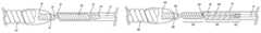
- FIG. 1is a schematic depiction of an embodiment of this invention wherein flexibility is introduced between the distal end of pusher wire 10 and embolic member 120 by helically wound wire 100 .
- FIG. 2is a schematic depiction of an embodiment of this invention wherein flexibility is introduced between distal end of pusher wire 10 and embolic member 480 by a helically wound wire comprised of two portions, 420 and 430 , which are independently open or closed-pitched.
- a helically wound wirecomprised of two portions, 420 and 430 , which are independently open or closed-pitched.
- the proximal portion 520is open-pitched and the distal portion 530 is closed-pitched.
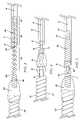
- FIG. 3is a schematic depiction of the embodiment shown in FIG. 2 wherein both the proximal portion 520 and the distal portion 530 of the helically wound segment are open-pitched.
- FIG. 4is a schematic depiction of a further embodiment of this invention wherein flexibility is conferred on the distal end of the device by virtue of interlinked loops 60 and 95 .
- FIG. 5is a schematic depiction of a still further embodiment of this invention wherein the flexibility-conferring features of the device in FIGS. 1 and 4 are combined; that is, the device in FIG. 5 comprises both a helically wound segment 100 and interlinked loops, 300 and 310 .
- FIG. 1schematically depicts an embodiment of the present invention.
- the distal end of pusher (or core, the terms are used interchangeably herein) wire 10is coupled to the proximal end of helical coil 100 by weld junction 110 .
- Helical coil 100may be open or closed pitch and the pitch itself can be varied to establish a desired degree of softness or pliability in region of the device.
- Pusher wire 10is encased in non-conducting substance 20 .
- Weld junction 110 and helical coil 100are also encased in non-conductive substance 20 .
- Weld junction 110 and helical coil 100are also encased in non-conductive substance 20 .
- Non-conducting substance 20can be any suitable insulating material such as poly(tetrafluoroethylene) (Teflon®), poly(paraxylene) (Parylene®), poly(ethylene terephthalate) (PET), poly(cyanoacrylates) and the like. PET is presently preferred.
- Pusher wire 10may be made of any material that has sufficient resilience/flexibility to permit accurate movement and placement of its distal end at a target site in a patient's body by manipulation of the wire at its proximal end, which may be many centimeters away. While this includes material such as carbon fiber and polymers, it is presently preferred that pusher wire 10 be stainless steel or nitinol.
- Helical coil 100likewise can be made of any conductive substance with the appropriate mechanical characteristics. It is presently preferred that helical coil 100 be of the same material as pusher wire 10 .
- Non-conductive bushing 50may optionally be included at the distal end of insulating layer 20 to provide additional isolation of electrolytic detachment site 30 from helical coil 100 .
- Detachment site 30is coupled to embolic assembly 120 by another conductive substance that has a different standard electrode potential (E 0 ) than that of detachment site 30 .
- E 0standard electrode potential
- the conductive substanceis shown as a wire helically-wound around detachment site 30 . This, however, is not to be construed as the only way to connect embolic assembly 120 and the delivery device. Any manner of connection such as wire winding, spot welds, pressure clips, etc. that permit close contact of the first conductive substance of detachment site 30 and the second conductive substance will suffice.
- Non-conductive substance 80can be any insulating substance, fusable polymers being particularly useful with PET being presently preferred.
- the proximal end of embolic assembly 120is also encased in non-conductive substance 80 .
- the conductive substance with the lower E 0will erode away resulting in release of embolic member 120 .
- connector 70is a conducting metal that has a different E 0 than the metal of which detachment site 30 is comprised. While any two metals that have the required E 0 difference may be used, it is presently preferred that separation locus 30 be stainless steel or nitinol and connector 70 be a platinum/tungsten alloy.
- Pusher wire 10is coupled to helically-wound segment 410 of wire 400 .
- Segment 420 of wire 400is open-pitched helically wound.
- Pusher wire 10 , segment 410 and segment 420 of wire 400are encased in non-conductive substance 20 .
- a non-conductive bushing 50may be attached to the distal end of non-conductive substance 20 to further isolate open-pitched segment 420 of wire 400 from closed-pitched segment 430 of wire 400 .
- Segment 430is optionally coated with a non-conductive substance, which may be the same substance used to encase pusher wire 10 and segment 420 or it may be a different non-conducting substance.
- a non-conductive substancewhich may be the same substance used to encase pusher wire 10 and segment 420 or it may be a different non-conducting substance.
- the term “encased”refers to the complete surrounding of an element of this invention such that the individual features of the element are not readily apparent from the outside of the encasing substance. Thus, the helically-wound nature of a wire encased in a substance would not be apparent to the casual observer.
- surface-coatedwhen used, it means that the element so-coated retained its appearance; i.e., a surface coated helically-wound wire appears to the casual observer as a helically wound wire.
- a typical example of “surface-coated”would be a common insulated electrical wire available for purchase at a hardware store. Pliable non-conductive materials such as those disclose above with regard to the first embodiment of this invention are presently preferred.
- the distal end of segment 430is bare and comprises detachment site 440 .
- the proximal end of helical coil 450is tightly wrapped around the distal portion of separation locus 440 to bind the two together.
- helical coil 450 and separation locus 440are made of metals or alloys having different values of E o . While coil 450 and locus 440 can be made of any metals or alloys that exhibit the required difference in E o , it is presently preferred that detachment site 440 be stainless steel or nitinol and helical coil 450 be a platinum/titanium alloy.
- detachment site 440be stainless steel or nitinol and helical coil 450 be a platinum/titanium alloy.
- the distal end of coil 450is embedded in a fusible, non-conductive polymeric mass 470 .
- the proximal end of embolic assembly 480is also embedded in polymeric mass 470 .
- Optional stretch-resistant member 460may be attached at one end to the distal end of pusher wire 10 and at the other end to detachment site 440 and threaded through the lumen described by the coiled segments of wire 400 .
- Member 460provides stretch resistance to wire 400 in the helical regions.
- Member 460may be made of any resilient, non-stretchable material. In general, polymeric materials having the requisite characteristics are most often used. Presently, polypropylene suture material is preferred. It is emphasize that FIG.
- segment 420is shown as open-pitched and segment 430 as closed-pitched, it is entirely possible, and it is within the scope of this invention, that this be reversed, i.e., that segment 420 be closed-pitched and segment 430 be open-pitched. Likewise, both segments can be closed-pitched or open pitched, this latter configuration being shown schematically in FIG. 3 .
- FIG. 2shows the point of separation of segments 420 and 430 as coincidently being the distal end of non-conductive substance 20 or, optionally, the distal end of non-conductive bushing 50 , such is not necessarily the case.
- non-conductive substance 20may be anywhere along the length of segment 420 or segment 430 .
- segment 430 and detachment site 440are shown being coupled to embolic assembly 480 by helically-wound wire 450 and non-conductive substance 450 .
- embolic assembly 480may be coupled to embolic assembly 480 by helically-wound wire 450 and non-conductive substance 450 .
- FIG. 4depicts yet another embodiment of this invention in which increased flexibility is introduced into the device by means of interlinking loops 60 and 95 .
- pusher wire 10is encased in non-conductive substance 20 , with enough of wire 10 being left exposed at its proximal end to attach to a power supply.
- a portion of its distal endis also left bare to provide detachment site 30 .
- Non-conductive substancecan be any of those discussed above with regard to the other embodiments of this invention.
- a non-conductive bushing 50may optionally be included to provide additional separation of the encased portion of pusher wire 10 from detachment site 30 .
- Electrolytic separation of embolic member 120is accomplished by virtue of connecting entity 70 , which comprises a metal having a different E o than that of pusher wire 10 .
- connecting entity 70which comprises a metal having a different E o than that of pusher wire 10 .
- the metal with the lower E 0will erode away resulting in release of embolic member 120 .
- embolic member 120is attached pusher wire 10 by a mass of non-conducting substance 80 , which may be the same as, or different than, the non-conducting substance that is used to encase pusher wire 10 .
- any combination of metals for core wire 10 and connector 70 that have the requisite difference in E omay be used, typically core wire 10 is stainless steel or nitinol and connector 70 is a platinum/zirconium alloy.
- Eyelet loop 60can be made of any non-conductive material. Presently preferred are those that can form a fiber or fiber-like structure. PET is a presently preferred substance with the desired characteristics.
- Embolic assembly member 40has a distal helically wound coil region 90 and an eyelet loop 95 , which is interlinked with eyelet loop 60 .
- region 90 of embolic assembly 40need not necessarily be a helically-wound wire but may simply be, for example without limitation, a straight segment of wire or even a flat piece of metal.
- FIG. 5is a schematic representation of yet another embodiment of this invention that combines the elements of the two embodiments above.
- the distal end of pusher wire 10is coupled to the proximal end of helical coil 100 by weld junction 110 .
- Helical coil 100may be open or closed pitch, and the pitch itself may be varied, to establish a desired degree of softness or pliability.
- Pusher wire 10 , weld junction 110 and helical coil 100are encased in non-conductive substance 20 .
- Non-conductive substance 20can be any of the materials mentioned above with regard to the first and second described embodiments of this invention or any other material that meets the requirements of the disclosures herein.
- non-conductive bushing 50may optionally be included at the distal end of insulating layer 20 to provide additional isolation of eyelet loop 300 , whereat electrolytic separation of embolic assembly 120 will occur.
- Coil 70 and eyelet loop 310are made of an electrically-conductive substance, preferably a metal or alloy that has a different E o from the substance, also preferably a metal, of which eyelet loop 300 is made. While any combination of metals or alloys that has the required difference in E o may be used, it is presently preferred that eyelet loop 300 be stainless steel and that eyelet loop 310 be a platinum/titanium alloy.
- Helical coil 70is embedded in a mass of non-conductive substance 80 .
- Substance 80can be any non-conductive material that can be melted or fused to encase the distal end of coil 70 and the proximal end of assembly 120 .
Landscapes
- Health & Medical Sciences (AREA)
- Surgery (AREA)
- Life Sciences & Earth Sciences (AREA)
- Heart & Thoracic Surgery (AREA)
- Molecular Biology (AREA)
- Vascular Medicine (AREA)
- Engineering & Computer Science (AREA)
- Biomedical Technology (AREA)
- Reproductive Health (AREA)
- Medical Informatics (AREA)
- Nuclear Medicine, Radiotherapy & Molecular Imaging (AREA)
- Animal Behavior & Ethology (AREA)
- General Health & Medical Sciences (AREA)
- Public Health (AREA)
- Veterinary Medicine (AREA)
- Neurosurgery (AREA)
- Surgical Instruments (AREA)
Abstract
Description
- a core wire comprising a first electrically-conductive substance that is at least partially fixedly encased in a first non-conductive substance and has a proximal and a distal end, its proximal end being connected to an electrical signal generator;
- a flexible member having a proximal and a distal end, its proximal end being coupled to the distal end of the core wire;
- an embolic assembly having a proximal and a distal end, its proximal end being operatively coupled to the distal end of the flexible member; and,
- an electrolytic detachment site located between the proximal end of the embolic assembly and a distal end of the first non-conductive substance.
- providing a delivery member capable of positioning a core wire in close proximity to a target site, the delivery member comprising a first elongate tube having a proximal end, a distal end and an axial lumen;
- providing a core wire slidably disposed within the axial lumen, the wire comprising a first electrically-conductive substance that is at least partially fixedly encased in a first non-conductive substance and has a proximal and a distal end, its proximal end being connected to an electrical signal generator;
- providing a flexible member having a proximal and a distal end, its proximal end being coupled to the distal end of the core wire;
- providing an embolic assembly having a proximal and a distal end, its proximal end being operatively coupled to the distal end of the flexible member; and,
- providing an electrolytic detachment site located between the proximal end of the embolic assembly and a distal end of the first conductive substance;
- moving the delivery member to a position in close proximity to the target site;
- sliding the core wire through the lumen of the delivery member until the embolic assembly is at or in the target site; and,
- sending an electrical signal to the electrolytic detachment site which results in release of the embolic assembly.
Claims (16)
Priority Applications (9)
| Application Number | Priority Date | Filing Date | Title |
|---|---|---|---|
| US10/407,295US7651513B2 (en) | 2003-04-03 | 2003-04-03 | Flexible embolic device delivery system |
| AT04759001TATE434419T1 (en) | 2003-04-03 | 2004-03-25 | FLEXIBLE EMBOLIC DEVICE DELIVERY SYSTEM |
| PCT/US2004/009364WO2004091713A2 (en) | 2003-04-03 | 2004-03-25 | Flexible embolic device delivery system |
| EP04759001AEP1615592B1 (en) | 2003-04-03 | 2004-03-25 | Flexible embolic device delivery system |
| ES04759001TES2328038T3 (en) | 2003-04-03 | 2004-03-25 | FLEXIBLE EMBOLISTIC DEVICE ADMINISTRATION SYSTEM. |
| CA2520754ACA2520754C (en) | 2003-04-03 | 2004-03-25 | Flexible embolic device delivery system |
| DE602004021684TDE602004021684D1 (en) | 2003-04-03 | 2004-03-25 | |
| JP2006509363AJP4617301B2 (en) | 2003-04-03 | 2004-03-25 | Flexible embolic device delivery system |
| US12/652,565US20100106162A1 (en) | 2003-04-03 | 2010-01-05 | Flexible embolic device delivery system |
Applications Claiming Priority (1)
| Application Number | Priority Date | Filing Date | Title |
|---|---|---|---|
| US10/407,295US7651513B2 (en) | 2003-04-03 | 2003-04-03 | Flexible embolic device delivery system |
Related Child Applications (1)
| Application Number | Title | Priority Date | Filing Date |
|---|---|---|---|
| US12/652,565ContinuationUS20100106162A1 (en) | 2003-04-03 | 2010-01-05 | Flexible embolic device delivery system |
Publications (2)
| Publication Number | Publication Date |
|---|---|
| US20040199175A1 US20040199175A1 (en) | 2004-10-07 |
| US7651513B2true US7651513B2 (en) | 2010-01-26 |
Family
ID=33097511
Family Applications (2)
| Application Number | Title | Priority Date | Filing Date |
|---|---|---|---|
| US10/407,295Active2027-10-11US7651513B2 (en) | 2003-04-03 | 2003-04-03 | Flexible embolic device delivery system |
| US12/652,565AbandonedUS20100106162A1 (en) | 2003-04-03 | 2010-01-05 | Flexible embolic device delivery system |
Family Applications After (1)
| Application Number | Title | Priority Date | Filing Date |
|---|---|---|---|
| US12/652,565AbandonedUS20100106162A1 (en) | 2003-04-03 | 2010-01-05 | Flexible embolic device delivery system |
Country Status (8)
| Country | Link |
|---|---|
| US (2) | US7651513B2 (en) |
| EP (1) | EP1615592B1 (en) |
| JP (1) | JP4617301B2 (en) |
| AT (1) | ATE434419T1 (en) |
| CA (1) | CA2520754C (en) |
| DE (1) | DE602004021684D1 (en) |
| ES (1) | ES2328038T3 (en) |
| WO (1) | WO2004091713A2 (en) |
Cited By (30)
| Publication number | Priority date | Publication date | Assignee | Title |
|---|---|---|---|---|
| US20090143786A1 (en)* | 2007-12-03 | 2009-06-04 | Boston Scientific Scimed, Inc. | Implantable device with electrolytically detachable junction having multiple fine wires and method of introduction |
| US20090163780A1 (en)* | 2007-12-21 | 2009-06-25 | Microvention, Inc. | System And Method For Locating Detachment Zone Of A Detachable Implant |
| US20090163986A1 (en)* | 2007-12-21 | 2009-06-25 | Microvention, Inc | System And Method Of Detecting Implant Detachment |
| US20090275971A1 (en)* | 2007-10-30 | 2009-11-05 | Boston Scientific Scimed, Inc. | Energy activated preloaded detachment mechanisms for implantable devices |
| US20110009950A1 (en)* | 2009-07-08 | 2011-01-13 | Concentric Medical, Inc. | Vascular and bodily duct treatment devices and methods |
| US20110009941A1 (en)* | 2009-07-08 | 2011-01-13 | Concentric Medical, Inc. | Vascular and bodily duct treatment devices and methods |
| US20110301686A1 (en)* | 2010-04-14 | 2011-12-08 | Microvention, Inc. | Implant Delivery Device |
| US20120203322A1 (en)* | 2011-02-07 | 2012-08-09 | Eells Robert M | Quick release mechanism for medical device deployment |
| US8357179B2 (en) | 2009-07-08 | 2013-01-22 | Concentric Medical, Inc. | Vascular and bodily duct treatment devices and methods |
| US8529596B2 (en) | 2009-07-08 | 2013-09-10 | Concentric Medical, Inc. | Vascular and bodily duct treatment devices and methods |
| US8795317B2 (en) | 2009-07-08 | 2014-08-05 | Concentric Medical, Inc. | Embolic obstruction retrieval devices and methods |
| US8795345B2 (en) | 2009-07-08 | 2014-08-05 | Concentric Medical, Inc. | Vascular and bodily duct treatment devices and methods |
| US9072537B2 (en) | 2009-07-08 | 2015-07-07 | Concentric Medical, Inc. | Vascular and bodily duct treatment devices and methods |
| US9220506B2 (en) | 2010-06-16 | 2015-12-29 | DePuy Synthes Products, Inc. | Occlusive device with stretch resistant member and anchor filament |
| US20160022271A1 (en)* | 2013-03-11 | 2016-01-28 | DeLois Marlene Ferry | Flat wound detachable embolization coil |
| US9254134B2 (en) | 2004-01-21 | 2016-02-09 | Dendron Gmbh | Device for implanting electrically isolated occlusion helixes |
| US9326774B2 (en) | 2012-08-03 | 2016-05-03 | Covidien Lp | Device for implantation of medical devices |
| US9717503B2 (en) | 2015-05-11 | 2017-08-01 | Covidien Lp | Electrolytic detachment for implant delivery systems |
| US9782178B2 (en) | 2014-09-19 | 2017-10-10 | DePuy Synthes Products, Inc. | Vasculature occlusion device detachment system with tapered corewire and heater activated fiber detachment |
| US9808599B2 (en) | 2013-12-20 | 2017-11-07 | Microvention, Inc. | Device delivery system |
| US9808256B2 (en) | 2014-08-08 | 2017-11-07 | Covidien Lp | Electrolytic detachment elements for implant delivery systems |
| US9814466B2 (en) | 2014-08-08 | 2017-11-14 | Covidien Lp | Electrolytic and mechanical detachment for implant delivery systems |
| US9855050B2 (en) | 2014-09-19 | 2018-01-02 | DePuy Synthes Products, Inc. | Vasculature occlusion device detachment system with tapered corewire and single loop fuse detachment |
| US10076335B2 (en) | 2005-12-01 | 2018-09-18 | Atritech, Inc. | Apparatus for delivering an implant without bias to a left atrial appendage |
| US10363086B2 (en) | 2014-10-31 | 2019-07-30 | Medtronic Advanced Energy Llc | Power monitoring circuitry and method for reducing leakage current in RF generators |
| US10639456B2 (en) | 2015-09-28 | 2020-05-05 | Microvention, Inc. | Guidewire with torque transmission element |
| US10828037B2 (en) | 2016-06-27 | 2020-11-10 | Covidien Lp | Electrolytic detachment with fluid electrical connection |
| US10828039B2 (en) | 2016-06-27 | 2020-11-10 | Covidien Lp | Electrolytic detachment for implantable devices |
| US11051822B2 (en) | 2016-06-28 | 2021-07-06 | Covidien Lp | Implant detachment with thermal activation |
| US12114863B2 (en) | 2018-12-05 | 2024-10-15 | Microvention, Inc. | Implant delivery system |
Families Citing this family (26)
| Publication number | Priority date | Publication date | Assignee | Title |
|---|---|---|---|---|
| US7608089B2 (en)* | 2004-12-22 | 2009-10-27 | Boston Scientific Scimed, Inc. | Vaso-occlusive device having pivotable coupling |
| WO2006126474A1 (en)* | 2005-05-24 | 2006-11-30 | Kaneka Corporation | Medical wire |
| US20060271097A1 (en)* | 2005-05-31 | 2006-11-30 | Kamal Ramzipoor | Electrolytically detachable implantable devices |
| US9636115B2 (en)* | 2005-06-14 | 2017-05-02 | Stryker Corporation | Vaso-occlusive delivery device with kink resistant, flexible distal end |
| GB0512319D0 (en)* | 2005-06-16 | 2005-07-27 | Angiomed Ag | Catheter device variable pusher |
| US7344558B2 (en)* | 2006-02-28 | 2008-03-18 | Cordis Development Corporation | Embolic device delivery system |
| US8366720B2 (en)* | 2006-07-31 | 2013-02-05 | Codman & Shurtleff, Inc. | Interventional medical device system having an elongation retarding portion and method of using the same |
| US8926650B2 (en)* | 2006-11-20 | 2015-01-06 | Boston Scientific Scimed, Inc. | Mechanically detachable vaso-occlusive device |
| US20080319522A1 (en)* | 2007-06-22 | 2008-12-25 | Von Lehe Cathleen | Aneurysm filler detacher |
| US20080319523A1 (en)* | 2007-06-22 | 2008-12-25 | Neuro Vasx, Inc | Aneurysm filler device |
| US9907555B2 (en)* | 2007-08-09 | 2018-03-06 | Boston Scientific Scimed, Inc. | Guided detachable interlock and method of use |
| EP2330985A4 (en) | 2008-09-04 | 2015-11-18 | Curaseal Inc | Inflatable devices for enteric fistula treatment |
| JP5432912B2 (en)* | 2008-09-30 | 2014-03-05 | テルモ株式会社 | Stent delivery system |
| CA2739603A1 (en)* | 2008-10-13 | 2010-04-22 | Stryker Corporation | Vaso-occlusive coil delivery system |
| US8657870B2 (en)* | 2009-06-26 | 2014-02-25 | Biosensors International Group, Ltd. | Implant delivery apparatus and methods with electrolytic release |
| US9474532B2 (en)* | 2009-09-09 | 2016-10-25 | Kaneka Corporation | Embolization coil |
| WO2012054178A1 (en)* | 2010-10-21 | 2012-04-26 | Boston Scientific Scimed, Inc. | Stent delivery system with a rolling membrane |
| EP2484310A1 (en)* | 2011-02-08 | 2012-08-08 | Biotronik AG | Heart valve prosthesis with flexible fixations and deployment device therefor |
| JP6122424B2 (en) | 2011-06-16 | 2017-04-26 | キュラシール インコーポレイテッド | Device for fistula treatment and related method |
| CN107137114A (en) | 2011-06-17 | 2017-09-08 | 库拉希尔公司 | The device and method treated for fistula |
| WO2013039829A1 (en)* | 2011-09-13 | 2013-03-21 | Stryker Corporation | Vaso-occlusive device |
| EP2668914A1 (en)* | 2012-06-01 | 2013-12-04 | Acandis GmbH & Co. KG | Implant system |
| US9101473B2 (en)* | 2013-03-07 | 2015-08-11 | Medtronic Vascular, Inc. | Venous valve repair prosthesis for treatment of chronic venous insufficiency |
| US9149278B2 (en)* | 2013-03-13 | 2015-10-06 | DePuy Synthes Products, Inc. | Occlusive device delivery system with mechanical detachment |
| US9629739B2 (en) | 2013-03-13 | 2017-04-25 | DePuy Synthes Products, LLC | Distal capture device for a self-expanding stent |
| CN112656476A (en)* | 2020-12-31 | 2021-04-16 | 微创神通医疗科技(上海)有限公司 | Embolism material and preparation method thereof |
Citations (43)
| Publication number | Priority date | Publication date | Assignee | Title |
|---|---|---|---|---|
| US4867173A (en)* | 1986-06-30 | 1989-09-19 | Meadox Surgimed A/S | Steerable guidewire |
| US4994069A (en) | 1988-11-02 | 1991-02-19 | Target Therapeutics | Vaso-occlusion coil and method |
| US5108407A (en) | 1990-06-08 | 1992-04-28 | Rush-Presbyterian St. Luke's Medical Center | Method and apparatus for placement of an embolic coil |
| US5122136A (en) | 1990-03-13 | 1992-06-16 | The Regents Of The University Of California | Endovascular electrolytically detachable guidewire tip for the electroformation of thrombus in arteries, veins, aneurysms, vascular malformations and arteriovenous fistulas |
| US5217484A (en) | 1991-06-07 | 1993-06-08 | Marks Michael P | Retractable-wire catheter device and method |
| US5234437A (en) | 1991-12-12 | 1993-08-10 | Target Therapeutics, Inc. | Detachable pusher-vasoocclusion coil assembly with threaded coupling |
| US5250071A (en) | 1992-09-22 | 1993-10-05 | Target Therapeutics, Inc. | Detachable embolic coil assembly using interlocking clasps and method of use |
| US5261916A (en) | 1991-12-12 | 1993-11-16 | Target Therapeutics | Detachable pusher-vasoocclusive coil assembly with interlocking ball and keyway coupling |
| US5304195A (en) | 1991-12-12 | 1994-04-19 | Target Therapeutics, Inc. | Detachable pusher-vasoocclusive coil assembly with interlocking coupling |
| US5350397A (en) | 1992-11-13 | 1994-09-27 | Target Therapeutics, Inc. | Axially detachable embolic coil assembly |
| US5354295A (en) | 1990-03-13 | 1994-10-11 | Target Therapeutics, Inc. | In an endovascular electrolytically detachable wire and tip for the formation of thrombus in arteries, veins, aneurysms, vascular malformations and arteriovenous fistulas |
| US5423829A (en)* | 1993-11-03 | 1995-06-13 | Target Therapeutics, Inc. | Electrolytically severable joint for endovascular embolic devices |
| US5624449A (en) | 1993-11-03 | 1997-04-29 | Target Therapeutics | Electrolytically severable joint for endovascular embolic devices |
| US5667767A (en) | 1995-07-27 | 1997-09-16 | Micro Therapeutics, Inc. | Compositions for use in embolizing blood vessels |
| US5669905A (en) | 1994-03-03 | 1997-09-23 | Target Therapeutics, Inc. | Endovascular embolic device detachment detection method and apparatus |
| US5690671A (en) | 1994-12-13 | 1997-11-25 | Micro Interventional Systems, Inc. | Embolic elements and methods and apparatus for their delivery |
| US5695480A (en) | 1996-07-29 | 1997-12-09 | Micro Therapeutics, Inc. | Embolizing compositions |
| US5702361A (en) | 1996-01-31 | 1997-12-30 | Micro Therapeutics, Inc. | Method for embolizing blood vessels |
| US5795331A (en) | 1994-01-24 | 1998-08-18 | Micro Therapeutics, Inc. | Balloon catheter for occluding aneurysms of branch vessels |
| US5830178A (en) | 1996-10-11 | 1998-11-03 | Micro Therapeutics, Inc. | Methods for embolizing vascular sites with an emboilizing composition comprising dimethylsulfoxide |
| US5855578A (en) | 1990-03-13 | 1999-01-05 | The Regents Of The University Of California | Endovascular electrolytically detachable wire and tip for the formation of thrombus in arteries, veins, aneurysms, vascular malformations and arteriovenous fistulas |
| US5891128A (en)* | 1994-12-30 | 1999-04-06 | Target Therapeutics, Inc. | Solderless electrolytically severable joint for detachable devices placed within the mammalian body |
| US5916235A (en) | 1997-08-13 | 1999-06-29 | The Regents Of The University Of California | Apparatus and method for the use of detachable coils in vascular aneurysms and body cavities |
| US5925062A (en) | 1992-09-02 | 1999-07-20 | Board Of Regents, The University Of Texas System | Intravascular device |
| US5935148A (en) | 1998-06-24 | 1999-08-10 | Target Therapeutics, Inc. | Detachable, varying flexibility, aneurysm neck bridge |
| US5941888A (en)* | 1998-02-18 | 1999-08-24 | Target Therapeutics, Inc. | Vaso-occlusive member assembly with multiple detaching points |
| US5964797A (en) | 1996-08-30 | 1999-10-12 | Target Therapeutics, Inc. | Electrolytically deployable braided vaso-occlusion device |
| US5984929A (en) | 1997-08-29 | 1999-11-16 | Target Therapeutics, Inc. | Fast detaching electronically isolated implant |
| US6059779A (en) | 1995-04-28 | 2000-05-09 | Target Therapeutics, Inc. | Delivery catheter for electrolytically detachable implant |
| US6063070A (en) | 1997-08-05 | 2000-05-16 | Target Therapeutics, Inc. | Detachable aneurysm neck bridge (II) |
| US6077260A (en) | 1998-02-19 | 2000-06-20 | Target Therapeutics, Inc. | Assembly containing an electrolytically severable joint for endovascular embolic devices |
| US6086577A (en) | 1997-08-13 | 2000-07-11 | Scimed Life Systems, Inc. | Detachable aneurysm neck bridge (III) |
| US6146373A (en) | 1997-10-17 | 2000-11-14 | Micro Therapeutics, Inc. | Catheter system and method for injection of a liquid embolic composition and a solidification agent |
| US6156061A (en) | 1997-08-29 | 2000-12-05 | Target Therapeutics, Inc. | Fast-detaching electrically insulated implant |
| US6193708B1 (en) | 1997-08-05 | 2001-02-27 | Scimed Life Systems, Inc. | Detachable aneurysm neck bridge (I) |
| US6231573B1 (en) | 1998-04-21 | 2001-05-15 | Medicorp, S.A. | Device for treating aneurysms |
| US6303100B1 (en) | 1999-03-19 | 2001-10-16 | Micro Therapeutics, Inc. | Methods for inhibiting the formation of potential endoleaks associated with endovascular repair of abdominal aortic aneurysms |
| US6342202B1 (en) | 1996-05-31 | 2002-01-29 | Micro Therapeutics, Inc. | Compositions for use in embolizing blood vessels |
| US6344041B1 (en) | 1996-07-26 | 2002-02-05 | David Kupiecki | Aneurysm closure device assembly |
| US6397850B1 (en) | 2000-02-09 | 2002-06-04 | Scimed Life Systems Inc | Dual-mode apparatus and method for detection of embolic device detachment |
| US6425893B1 (en) | 1990-03-13 | 2002-07-30 | The Regents Of The University Of California | Method and apparatus for fast electrolytic detachment of an implant |
| US20040078050A1 (en)* | 1999-10-30 | 2004-04-22 | Hermann Monstadt | Device for implanting occlusion coils |
| US7238194B2 (en)* | 2001-04-10 | 2007-07-03 | Dendron Gmbh | Device for implanting occlusion spirals |
Family Cites Families (3)
| Publication number | Priority date | Publication date | Assignee | Title |
|---|---|---|---|---|
| US5106407A (en)* | 1984-05-04 | 1992-04-21 | The Dow Chemical Company | Iodones and methods for antimicrobial use |
| US5853418A (en)* | 1995-06-30 | 1998-12-29 | Target Therapeutics, Inc. | Stretch resistant vaso-occlusive coils (II) |
| GB9515986D0 (en)* | 1995-08-04 | 1995-10-04 | Racal Health & Safety Ltd | Uni-directional fluid valve |
- 2003
- 2003-04-03USUS10/407,295patent/US7651513B2/enactiveActive
- 2004
- 2004-03-25CACA2520754Apatent/CA2520754C/ennot_activeExpired - Fee Related
- 2004-03-25ESES04759001Tpatent/ES2328038T3/ennot_activeExpired - Lifetime
- 2004-03-25EPEP04759001Apatent/EP1615592B1/ennot_activeExpired - Lifetime
- 2004-03-25DEDE602004021684Tpatent/DE602004021684D1/denot_activeExpired - Lifetime
- 2004-03-25ATAT04759001Tpatent/ATE434419T1/ennot_activeIP Right Cessation
- 2004-03-25WOPCT/US2004/009364patent/WO2004091713A2/enactiveApplication Filing
- 2004-03-25JPJP2006509363Apatent/JP4617301B2/ennot_activeExpired - Lifetime
- 2010
- 2010-01-05USUS12/652,565patent/US20100106162A1/ennot_activeAbandoned
Patent Citations (59)
| Publication number | Priority date | Publication date | Assignee | Title |
|---|---|---|---|---|
| US4867173A (en)* | 1986-06-30 | 1989-09-19 | Meadox Surgimed A/S | Steerable guidewire |
| US4994069A (en) | 1988-11-02 | 1991-02-19 | Target Therapeutics | Vaso-occlusion coil and method |
| US5855578A (en) | 1990-03-13 | 1999-01-05 | The Regents Of The University Of California | Endovascular electrolytically detachable wire and tip for the formation of thrombus in arteries, veins, aneurysms, vascular malformations and arteriovenous fistulas |
| US5925037A (en) | 1990-03-13 | 1999-07-20 | The Regents Of The University Of California | Endovascular electrolytically detachable wire and tip for the formation of thrombus in arteries, veins, aneurysms, vascular malformations and arteriovenous fistulas |
| US5944714A (en) | 1990-03-13 | 1999-08-31 | The Regents Of The University Of California | Endovascular electrolytically detachable wire and tip for the formation of thrombus in arteries, veins, aneurysms, vascular malformations and arteriovenous fistulas |
| US5976126A (en) | 1990-03-13 | 1999-11-02 | The Regents Of The University Of California | Endovascular electrolytically detachable wire and tip formation of thrombus in arteries, veins, aneurysms, vascular malformations and arteriovenous fistulas |
| US5928226A (en) | 1990-03-13 | 1999-07-27 | The Regents Of The University Of California | Endovascular electrolytically detachable wire and tip for the formation of thrombus in arteries, veins, aneurysms, vascular malformations and arteriovenous fistulas |
| US5895385A (en) | 1990-03-13 | 1999-04-20 | The Regents Of The University Of California | Endovascular electrolytically detachable wire and tip for the formation of thrombus in arteries, veins, aneurysms, vascular malformations and arteriovenous fistulas |
| US6010498A (en) | 1990-03-13 | 2000-01-04 | The Regents Of The University Of California | Endovascular electrolytically detachable wire and tip for the formation of thrombus in arteries, veins, aneurysms, vascular malformations and arteriovenous fistulas |
| US6066133A (en) | 1990-03-13 | 2000-05-23 | The Regents Of The University Of California | Endovascular electrolytically detachable wire and tip for the formation of thrombus in arteries, veins, aneurysms, vascular malformations and arteriovenous fistulas |
| US5354295A (en) | 1990-03-13 | 1994-10-11 | Target Therapeutics, Inc. | In an endovascular electrolytically detachable wire and tip for the formation of thrombus in arteries, veins, aneurysms, vascular malformations and arteriovenous fistulas |
| US5947963A (en) | 1990-03-13 | 1999-09-07 | The Regents Of The University Of California | Endovascular electrolytically detachable wire and tip for the formation of thrombus in arteries, veins, aneurysms, vascular malformations and arteriovenous fistulas |
| US5540680A (en) | 1990-03-13 | 1996-07-30 | The Regents Of The University Of California | Endovascular electrolytically detachable wire and tip for the formation of thrombus in arteries, veins, aneurysms, vascular malformations and arteriovenous fistulas |
| US6083220A (en) | 1990-03-13 | 2000-07-04 | The Regents Of The University Of California | Endovascular electrolytically detachable wire and tip for the formation of thrombus in arteries, veins, aneurysms, vascular malformations and arteriovenous fistulas |
| US5122136A (en) | 1990-03-13 | 1992-06-16 | The Regents Of The University Of California | Endovascular electrolytically detachable guidewire tip for the electroformation of thrombus in arteries, veins, aneurysms, vascular malformations and arteriovenous fistulas |
| US6425893B1 (en) | 1990-03-13 | 2002-07-30 | The Regents Of The University Of California | Method and apparatus for fast electrolytic detachment of an implant |
| US5947962A (en) | 1990-03-13 | 1999-09-07 | The Regents Of The University Of California | Endovascular electrolytically detachable wire and tip for the formation of thrombus in arteries veins aneurysms vascular malformations and arteriovenous fistulas |
| US5108407A (en) | 1990-06-08 | 1992-04-28 | Rush-Presbyterian St. Luke's Medical Center | Method and apparatus for placement of an embolic coil |
| US5217484A (en) | 1991-06-07 | 1993-06-08 | Marks Michael P | Retractable-wire catheter device and method |
| US5304195A (en) | 1991-12-12 | 1994-04-19 | Target Therapeutics, Inc. | Detachable pusher-vasoocclusive coil assembly with interlocking coupling |
| US5261916A (en) | 1991-12-12 | 1993-11-16 | Target Therapeutics | Detachable pusher-vasoocclusive coil assembly with interlocking ball and keyway coupling |
| US5234437A (en) | 1991-12-12 | 1993-08-10 | Target Therapeutics, Inc. | Detachable pusher-vasoocclusion coil assembly with threaded coupling |
| US5925062A (en) | 1992-09-02 | 1999-07-20 | Board Of Regents, The University Of Texas System | Intravascular device |
| US5250071A (en) | 1992-09-22 | 1993-10-05 | Target Therapeutics, Inc. | Detachable embolic coil assembly using interlocking clasps and method of use |
| US5891130A (en) | 1992-11-13 | 1999-04-06 | Target Therapeutics, Inc. | Axially detachable embolic coil assembly |
| US5350397A (en) | 1992-11-13 | 1994-09-27 | Target Therapeutics, Inc. | Axially detachable embolic coil assembly |
| US5624449A (en) | 1993-11-03 | 1997-04-29 | Target Therapeutics | Electrolytically severable joint for endovascular embolic devices |
| US5423829A (en)* | 1993-11-03 | 1995-06-13 | Target Therapeutics, Inc. | Electrolytically severable joint for endovascular embolic devices |
| US5795331A (en) | 1994-01-24 | 1998-08-18 | Micro Therapeutics, Inc. | Balloon catheter for occluding aneurysms of branch vessels |
| US5669905A (en) | 1994-03-03 | 1997-09-23 | Target Therapeutics, Inc. | Endovascular embolic device detachment detection method and apparatus |
| US5690671A (en) | 1994-12-13 | 1997-11-25 | Micro Interventional Systems, Inc. | Embolic elements and methods and apparatus for their delivery |
| US5891128A (en)* | 1994-12-30 | 1999-04-06 | Target Therapeutics, Inc. | Solderless electrolytically severable joint for detachable devices placed within the mammalian body |
| US6059779A (en) | 1995-04-28 | 2000-05-09 | Target Therapeutics, Inc. | Delivery catheter for electrolytically detachable implant |
| US5667767A (en) | 1995-07-27 | 1997-09-16 | Micro Therapeutics, Inc. | Compositions for use in embolizing blood vessels |
| US5702361A (en) | 1996-01-31 | 1997-12-30 | Micro Therapeutics, Inc. | Method for embolizing blood vessels |
| US6017977A (en) | 1996-01-31 | 2000-01-25 | Micro Therapeutics, Inc. | Methods for embolizing blood vessels |
| US6281263B1 (en) | 1996-01-31 | 2001-08-28 | Scott Evans | Methods for embolizing blood vessels |
| US6342202B1 (en) | 1996-05-31 | 2002-01-29 | Micro Therapeutics, Inc. | Compositions for use in embolizing blood vessels |
| US6344041B1 (en) | 1996-07-26 | 2002-02-05 | David Kupiecki | Aneurysm closure device assembly |
| US5695480A (en) | 1996-07-29 | 1997-12-09 | Micro Therapeutics, Inc. | Embolizing compositions |
| US5964797A (en) | 1996-08-30 | 1999-10-12 | Target Therapeutics, Inc. | Electrolytically deployable braided vaso-occlusion device |
| US5830178A (en) | 1996-10-11 | 1998-11-03 | Micro Therapeutics, Inc. | Methods for embolizing vascular sites with an emboilizing composition comprising dimethylsulfoxide |
| US6063070A (en) | 1997-08-05 | 2000-05-16 | Target Therapeutics, Inc. | Detachable aneurysm neck bridge (II) |
| US6193708B1 (en) | 1997-08-05 | 2001-02-27 | Scimed Life Systems, Inc. | Detachable aneurysm neck bridge (I) |
| US5916235A (en) | 1997-08-13 | 1999-06-29 | The Regents Of The University Of California | Apparatus and method for the use of detachable coils in vascular aneurysms and body cavities |
| US6086577A (en) | 1997-08-13 | 2000-07-11 | Scimed Life Systems, Inc. | Detachable aneurysm neck bridge (III) |
| US6156061A (en) | 1997-08-29 | 2000-12-05 | Target Therapeutics, Inc. | Fast-detaching electrically insulated implant |
| US6165178A (en) | 1997-08-29 | 2000-12-26 | Scimed Life Systems, Inc. | Fast detaching electrically isolated implant |
| US5984929A (en) | 1997-08-29 | 1999-11-16 | Target Therapeutics, Inc. | Fast detaching electronically isolated implant |
| US6146373A (en) | 1997-10-17 | 2000-11-14 | Micro Therapeutics, Inc. | Catheter system and method for injection of a liquid embolic composition and a solidification agent |
| US5941888A (en)* | 1998-02-18 | 1999-08-24 | Target Therapeutics, Inc. | Vaso-occlusive member assembly with multiple detaching points |
| US6077260A (en) | 1998-02-19 | 2000-06-20 | Target Therapeutics, Inc. | Assembly containing an electrolytically severable joint for endovascular embolic devices |
| US6231573B1 (en) | 1998-04-21 | 2001-05-15 | Medicorp, S.A. | Device for treating aneurysms |
| US6063104A (en) | 1998-06-24 | 2000-05-16 | Target Therapeutics, Inc. | Detachable, varying flexibility, aneurysm neck bridge |
| US5935148A (en) | 1998-06-24 | 1999-08-10 | Target Therapeutics, Inc. | Detachable, varying flexibility, aneurysm neck bridge |
| US6303100B1 (en) | 1999-03-19 | 2001-10-16 | Micro Therapeutics, Inc. | Methods for inhibiting the formation of potential endoleaks associated with endovascular repair of abdominal aortic aneurysms |
| US20040078050A1 (en)* | 1999-10-30 | 2004-04-22 | Hermann Monstadt | Device for implanting occlusion coils |
| US6397850B1 (en) | 2000-02-09 | 2002-06-04 | Scimed Life Systems Inc | Dual-mode apparatus and method for detection of embolic device detachment |
| US7238194B2 (en)* | 2001-04-10 | 2007-07-03 | Dendron Gmbh | Device for implanting occlusion spirals |
Non-Patent Citations (2)
| Title |
|---|
| PCT International Search Report for PCT/US2004/009364, Applicant: Scimed Life Systems, Inc. Forms PCT/ISA/210 and 220, dated Oct. 18, 2004 (9 pages). |
| PCT Written Opinion of the International Search Authority for PCT/US2004/009364, Applicant: Scimed Life Systems, Inc, Form PCT/ISA/237, dated Oct. 18, 2004 (6 pages). |
Cited By (57)
| Publication number | Priority date | Publication date | Assignee | Title |
|---|---|---|---|---|
| US9254134B2 (en) | 2004-01-21 | 2016-02-09 | Dendron Gmbh | Device for implanting electrically isolated occlusion helixes |
| US10898198B2 (en) | 2005-12-01 | 2021-01-26 | Atritech, Inc. | Apparatus for delivering an implant without bias to a left atrial appendage |
| US10076335B2 (en) | 2005-12-01 | 2018-09-18 | Atritech, Inc. | Apparatus for delivering an implant without bias to a left atrial appendage |
| US20090275971A1 (en)* | 2007-10-30 | 2009-11-05 | Boston Scientific Scimed, Inc. | Energy activated preloaded detachment mechanisms for implantable devices |
| US20090143786A1 (en)* | 2007-12-03 | 2009-06-04 | Boston Scientific Scimed, Inc. | Implantable device with electrolytically detachable junction having multiple fine wires and method of introduction |
| US8460332B2 (en) | 2007-12-21 | 2013-06-11 | Microvention, Inc. | System and method of detecting implant detachment |
| US20090163780A1 (en)* | 2007-12-21 | 2009-06-25 | Microvention, Inc. | System And Method For Locating Detachment Zone Of A Detachable Implant |
| US20090163986A1 (en)* | 2007-12-21 | 2009-06-25 | Microvention, Inc | System And Method Of Detecting Implant Detachment |
| US10299755B2 (en) | 2007-12-21 | 2019-05-28 | Microvention, Inc. | System and method for locating detachment zone of a detachable implant |
| US8192480B2 (en) | 2007-12-21 | 2012-06-05 | Microvention, Inc. | System and method of detecting implant detachment |
| US9242070B2 (en) | 2007-12-21 | 2016-01-26 | MicronVention, Inc. | System and method for locating detachment zone of a detachable implant |
| US8357178B2 (en)* | 2009-07-08 | 2013-01-22 | Concentric Medical, Inc. | Vascular and bodily duct treatment devices and methods |
| US8529596B2 (en) | 2009-07-08 | 2013-09-10 | Concentric Medical, Inc. | Vascular and bodily duct treatment devices and methods |
| US8795317B2 (en) | 2009-07-08 | 2014-08-05 | Concentric Medical, Inc. | Embolic obstruction retrieval devices and methods |
| US8795345B2 (en) | 2009-07-08 | 2014-08-05 | Concentric Medical, Inc. | Vascular and bodily duct treatment devices and methods |
| US9044263B2 (en) | 2009-07-08 | 2015-06-02 | Concentric Medical, Inc. | Vascular and bodily duct treatment devices and methods |
| US9072537B2 (en) | 2009-07-08 | 2015-07-07 | Concentric Medical, Inc. | Vascular and bodily duct treatment devices and methods |
| US20110009950A1 (en)* | 2009-07-08 | 2011-01-13 | Concentric Medical, Inc. | Vascular and bodily duct treatment devices and methods |
| US8357179B2 (en) | 2009-07-08 | 2013-01-22 | Concentric Medical, Inc. | Vascular and bodily duct treatment devices and methods |
| US20110009941A1 (en)* | 2009-07-08 | 2011-01-13 | Concentric Medical, Inc. | Vascular and bodily duct treatment devices and methods |
| US20110301686A1 (en)* | 2010-04-14 | 2011-12-08 | Microvention, Inc. | Implant Delivery Device |
| US9561125B2 (en)* | 2010-04-14 | 2017-02-07 | Microvention, Inc. | Implant delivery device |
| US20170100126A1 (en)* | 2010-04-14 | 2017-04-13 | Microvention, Inc. | Implant delivery device |
| US10517604B2 (en) | 2010-04-14 | 2019-12-31 | Microvention, Inc. | Implant delivery device |
| US12114864B2 (en)* | 2010-04-14 | 2024-10-15 | Microvention, Inc. | Implant delivery device |
| US20220265277A1 (en)* | 2010-04-14 | 2022-08-25 | Microvention, Inc. | Implant Delivery Device |
| US11357513B2 (en) | 2010-04-14 | 2022-06-14 | Microvention, Inc. | Implant delivery device |
| US9220506B2 (en) | 2010-06-16 | 2015-12-29 | DePuy Synthes Products, Inc. | Occlusive device with stretch resistant member and anchor filament |
| US20120203322A1 (en)* | 2011-02-07 | 2012-08-09 | Eells Robert M | Quick release mechanism for medical device deployment |
| US9326774B2 (en) | 2012-08-03 | 2016-05-03 | Covidien Lp | Device for implantation of medical devices |
| US20160022271A1 (en)* | 2013-03-11 | 2016-01-28 | DeLois Marlene Ferry | Flat wound detachable embolization coil |
| US11744992B2 (en) | 2013-12-20 | 2023-09-05 | Microvention, Inc. | Segmented embolic system |
| US10682497B2 (en) | 2013-12-20 | 2020-06-16 | Microvention, Inc. | Steerable guidewire system |
| US9808599B2 (en) | 2013-12-20 | 2017-11-07 | Microvention, Inc. | Device delivery system |
| US12226597B2 (en) | 2013-12-20 | 2025-02-18 | MicroVention, Inc.. | Segmented embolic system |
| US10722687B2 (en) | 2013-12-20 | 2020-07-28 | Microvention, Inc. | Segmented embolic system |
| US9814466B2 (en) | 2014-08-08 | 2017-11-14 | Covidien Lp | Electrolytic and mechanical detachment for implant delivery systems |
| US10874401B2 (en) | 2014-08-08 | 2020-12-29 | Covidien Lp | Electrolytic and mechanical detachment for implant delivery systems |
| US11839380B2 (en) | 2014-08-08 | 2023-12-12 | Covidien Lp | Electrolytic and mechanical detachment for implant delivery systems |
| US9808256B2 (en) | 2014-08-08 | 2017-11-07 | Covidien Lp | Electrolytic detachment elements for implant delivery systems |
| US9855050B2 (en) | 2014-09-19 | 2018-01-02 | DePuy Synthes Products, Inc. | Vasculature occlusion device detachment system with tapered corewire and single loop fuse detachment |
| US10639043B2 (en) | 2014-09-19 | 2020-05-05 | DePuy Synthes Products, Inc. | Vasculature occlusion device detachment system with tapered corewire and heater activated fiber detachment |
| US9782178B2 (en) | 2014-09-19 | 2017-10-10 | DePuy Synthes Products, Inc. | Vasculature occlusion device detachment system with tapered corewire and heater activated fiber detachment |
| US10524851B2 (en) | 2014-10-31 | 2020-01-07 | Medtronic Advanced Energy Llc | Fingerswitch circuitry to reduce RF leakage current |
| US10405915B2 (en) | 2014-10-31 | 2019-09-10 | Medtronic Advanced Energy Llc | RF output stage switching mechanism |
| US10363086B2 (en) | 2014-10-31 | 2019-07-30 | Medtronic Advanced Energy Llc | Power monitoring circuitry and method for reducing leakage current in RF generators |
| US11399885B2 (en) | 2014-10-31 | 2022-08-02 | Medtronic Advanced Energy Llc | Power monitoring circuitry and method for reducing leakage current in RF generators |
| US11426228B2 (en) | 2014-10-31 | 2022-08-30 | Medtronic Advanced Energy Llc | RF output stage switching mechanism |
| US9717503B2 (en) | 2015-05-11 | 2017-08-01 | Covidien Lp | Electrolytic detachment for implant delivery systems |
| US10639456B2 (en) | 2015-09-28 | 2020-05-05 | Microvention, Inc. | Guidewire with torque transmission element |
| US10828039B2 (en) | 2016-06-27 | 2020-11-10 | Covidien Lp | Electrolytic detachment for implantable devices |
| US12064119B2 (en) | 2016-06-27 | 2024-08-20 | Covidien Lp | Electrolytic detachment for implantable devices |
| US10828037B2 (en) | 2016-06-27 | 2020-11-10 | Covidien Lp | Electrolytic detachment with fluid electrical connection |
| US12220130B2 (en) | 2016-06-27 | 2025-02-11 | Covidien Lp | Electrolytic detachment with fluid electrical connection |
| US11051822B2 (en) | 2016-06-28 | 2021-07-06 | Covidien Lp | Implant detachment with thermal activation |
| US12357316B2 (en) | 2016-06-28 | 2025-07-15 | Covidien Lp | Implant detachment with thermal activation |
| US12114863B2 (en) | 2018-12-05 | 2024-10-15 | Microvention, Inc. | Implant delivery system |
Also Published As
| Publication number | Publication date |
|---|---|
| US20040199175A1 (en) | 2004-10-07 |
| ES2328038T3 (en) | 2009-11-06 |
| ATE434419T1 (en) | 2009-07-15 |
| US20100106162A1 (en) | 2010-04-29 |
| JP2006521880A (en) | 2006-09-28 |
| WO2004091713A3 (en) | 2004-12-02 |
| JP4617301B2 (en) | 2011-01-26 |
| CA2520754A1 (en) | 2004-10-28 |
| WO2004091713A2 (en) | 2004-10-28 |
| EP1615592A2 (en) | 2006-01-18 |
| DE602004021684D1 (en) | 2009-08-06 |
| CA2520754C (en) | 2011-11-15 |
| EP1615592B1 (en) | 2009-06-24 |
Similar Documents
| Publication | Publication Date | Title |
|---|---|---|
| US7651513B2 (en) | Flexible embolic device delivery system | |
| EP2444010B1 (en) | Medical implant detachment systems | |
| US5759161A (en) | Medical wire and method for leaving implanted devices | |
| CA2214168C (en) | Electrolytically deployable braided vaso-occlusion device | |
| US6425893B1 (en) | Method and apparatus for fast electrolytic detachment of an implant | |
| EP0715502B1 (en) | Electrolytically severable coil assembly with movable detachment point | |
| EP2007290B1 (en) | Electro-active polymer apparatus for the deployment of vaso-occlusive coils | |
| US5891058A (en) | Coiled embolizing material | |
| US20060271097A1 (en) | Electrolytically detachable implantable devices | |
| US20090143786A1 (en) | Implantable device with electrolytically detachable junction having multiple fine wires and method of introduction | |
| JPH10198A (en) | Stretch resistant vascular blocking coil | |
| EP2668914A1 (en) | Implant system | |
| US11974756B2 (en) | Embolic coil and detachment system |
Legal Events
| Date | Code | Title | Description |
|---|---|---|---|
| AS | Assignment | Owner name:SCIMED LIFE SYSTEMS, INC., MINNESOTA Free format text:ASSIGNMENT OF ASSIGNORS INTEREST;ASSIGNORS:TEOH, CLIFFORD;PORTER, STEPHEN C.;JAEGER, KEVIN M.;AND OTHERS;REEL/FRAME:013944/0310 Effective date:20030402 | |
| AS | Assignment | Owner name:SCIMED LIFE SYSTEMS, INC., MINNESOTA Free format text:ASSIGNMENT OF ASSIGNORS INTEREST;ASSIGNOR:PIZARRO, MARIA;REEL/FRAME:014040/0855 Effective date:20030923 | |
| AS | Assignment | Owner name:BOSTON SCIENTIFIC SCIMED, INC., MINNESOTA Free format text:CHANGE OF NAME;ASSIGNOR:SCIMED LIFE SYSTEMS, INC.;REEL/FRAME:018505/0868 Effective date:20050101 Owner name:BOSTON SCIENTIFIC SCIMED, INC.,MINNESOTA Free format text:CHANGE OF NAME;ASSIGNOR:SCIMED LIFE SYSTEMS, INC.;REEL/FRAME:018505/0868 Effective date:20050101 | |
| FEPP | Fee payment procedure | Free format text:PAYOR NUMBER ASSIGNED (ORIGINAL EVENT CODE: ASPN); ENTITY STATUS OF PATENT OWNER: LARGE ENTITY | |
| STCF | Information on status: patent grant | Free format text:PATENTED CASE | |
| CC | Certificate of correction | ||
| CC | Certificate of correction | ||
| FEPP | Fee payment procedure | Free format text:PAYER NUMBER DE-ASSIGNED (ORIGINAL EVENT CODE: RMPN); ENTITY STATUS OF PATENT OWNER: LARGE ENTITY Free format text:PAYOR NUMBER ASSIGNED (ORIGINAL EVENT CODE: ASPN); ENTITY STATUS OF PATENT OWNER: LARGE ENTITY | |
| AS | Assignment | Owner name:STRYKER NV OPERATIONS LIMITED, IRELAND Free format text:ASSIGNMENT OF ASSIGNORS INTEREST;ASSIGNOR:BOSTON SCIENTIFIC SCIMED, INC.;REEL/FRAME:025969/0841 Effective date:20110103 Owner name:STRYKER CORPORATION, MICHIGAN Free format text:ASSIGNMENT OF ASSIGNORS INTEREST;ASSIGNOR:BOSTON SCIENTIFIC SCIMED, INC.;REEL/FRAME:025969/0841 Effective date:20110103 | |
| FPAY | Fee payment | Year of fee payment:4 | |
| AS | Assignment | Owner name:STRYKER MEDTECH LIMITED, MALTA Free format text:NUNC PRO TUNC ASSIGNMENT;ASSIGNOR:STRYKER NV OPERATIONS LIMITED;REEL/FRAME:037153/0034 Effective date:20151013 Owner name:STRYKER EUROPEAN HOLDINGS I, LLC, MICHIGAN Free format text:NUNC PRO TUNC ASSIGNMENT;ASSIGNOR:STRYKER MEDTECH LIMITED;REEL/FRAME:037153/0241 Effective date:20151013 | |
| AS | Assignment | Owner name:STRYKER EUROPEAN HOLDINGS I, LLC, MICHIGAN Free format text:CORRECTIVE ASSIGNMENT TO CORRECT THE INCORRECT LISTED SERIAL NOS. 09/905,670 AND 07/092,079 PREVIOUSLY RECORDED AT REEL: 037153 FRAME: 0241. ASSIGNOR(S) HEREBY CONFIRMS THE NUNC PRO TUNC ASSIGNMENT EFFECTIVE DATE 9/29/2014;ASSIGNOR:STRYKER MEDTECH LIMITED;REEL/FRAME:038043/0011 Effective date:20151013 Owner name:STRYKER MEDTECH LIMITED, MALTA Free format text:CORRECTIVE ASSIGNMENT TO CORRECT THE INCORRECT SERIAL # 09/905,670 AND 07/092,079 PREVIOUSLY RECORDED AT REEL: 037153 FRAME: 0034. ASSIGNOR(S) HEREBY CONFIRMS THE NUNC PRO TUNC ASSIGNMENT;ASSIGNOR:STRYKER NV OPERATIONS LIMITED;REEL/FRAME:038039/0001 Effective date:20151013 | |
| FPAY | Fee payment | Year of fee payment:8 | |
| AS | Assignment | Owner name:STRYKER EUROPEAN OPERATIONS HOLDINGS LLC, MICHIGAN Free format text:CHANGE OF NAME;ASSIGNOR:STRYKER EUROPEAN HOLDINGS III, LLC;REEL/FRAME:052860/0716 Effective date:20190226 Owner name:STRYKER EUROPEAN HOLDINGS III, LLC, DELAWARE Free format text:NUNC PRO TUNC ASSIGNMENT;ASSIGNOR:STRYKER EUROPEAN HOLDINGS I, LLC;REEL/FRAME:052861/0001 Effective date:20200519 | |
| MAFP | Maintenance fee payment | Free format text:PAYMENT OF MAINTENANCE FEE, 12TH YEAR, LARGE ENTITY (ORIGINAL EVENT CODE: M1553); ENTITY STATUS OF PATENT OWNER: LARGE ENTITY Year of fee payment:12 | |
| AS | Assignment | Owner name:STRYKER CORPORATION, MICHIGAN Free format text:CHANGE OF ADDRESS;ASSIGNOR:STRYKER CORPORATION;REEL/FRAME:069737/0184 Effective date:20241217 Owner name:STRYKER EUROPEAN OPERATIONS HOLDINGS LLC, MICHIGAN Free format text:CHANGE OF ADDRESS;ASSIGNOR:STRYKER EUROPEAN OPERATIONS HOLDINGS LLC;REEL/FRAME:069730/0754 Effective date:20241217 |