US7651481B2 - Self-sealing male connector device with collapsible body - Google Patents
Self-sealing male connector device with collapsible bodyDownload PDFInfo
- Publication number
- US7651481B2 US7651481B2US11/026,002US2600204AUS7651481B2US 7651481 B2US7651481 B2US 7651481B2US 2600204 AUS2600204 AUS 2600204AUS 7651481 B2US7651481 B2US 7651481B2
- Authority
- US
- United States
- Prior art keywords
- connector device
- male
- closure cap
- diameter
- male body
- Prior art date
- Legal status (The legal status is an assumption and is not a legal conclusion. Google has not performed a legal analysis and makes no representation as to the accuracy of the status listed.)
- Active, expires
Links
Images


Classifications
- A—HUMAN NECESSITIES
- A61—MEDICAL OR VETERINARY SCIENCE; HYGIENE
- A61M—DEVICES FOR INTRODUCING MEDIA INTO, OR ONTO, THE BODY; DEVICES FOR TRANSDUCING BODY MEDIA OR FOR TAKING MEDIA FROM THE BODY; DEVICES FOR PRODUCING OR ENDING SLEEP OR STUPOR
- A61M39/00—Tubes, tube connectors, tube couplings, valves, access sites or the like, specially adapted for medical use
- A61M39/10—Tube connectors; Tube couplings
- A61M39/1011—Locking means for securing connection; Additional tamper safeties
- A—HUMAN NECESSITIES
- A61—MEDICAL OR VETERINARY SCIENCE; HYGIENE
- A61B—DIAGNOSIS; SURGERY; IDENTIFICATION
- A61B5/00—Measuring for diagnostic purposes; Identification of persons
- A61B5/15—Devices for taking samples of blood
- A61B5/150007—Details
- A61B5/150015—Source of blood
- A61B5/15003—Source of blood for venous or arterial blood
- A—HUMAN NECESSITIES
- A61—MEDICAL OR VETERINARY SCIENCE; HYGIENE
- A61B—DIAGNOSIS; SURGERY; IDENTIFICATION
- A61B5/00—Measuring for diagnostic purposes; Identification of persons
- A61B5/15—Devices for taking samples of blood
- A61B5/150007—Details
- A61B5/150351—Caps, stoppers or lids for sealing or closing a blood collection vessel or container, e.g. a test-tube or syringe barrel
- A—HUMAN NECESSITIES
- A61—MEDICAL OR VETERINARY SCIENCE; HYGIENE
- A61B—DIAGNOSIS; SURGERY; IDENTIFICATION
- A61B5/00—Measuring for diagnostic purposes; Identification of persons
- A61B5/15—Devices for taking samples of blood
- A61B5/150992—Blood sampling from a fluid line external to a patient, such as a catheter line, combined with an infusion line; Blood sampling from indwelling needle sets, e.g. sealable ports, luer couplings or valves
- A—HUMAN NECESSITIES
- A61—MEDICAL OR VETERINARY SCIENCE; HYGIENE
- A61B—DIAGNOSIS; SURGERY; IDENTIFICATION
- A61B5/00—Measuring for diagnostic purposes; Identification of persons
- A61B5/15—Devices for taking samples of blood
- A61B5/153—Devices specially adapted for taking samples of venous or arterial blood, e.g. with syringes
- A—HUMAN NECESSITIES
- A61—MEDICAL OR VETERINARY SCIENCE; HYGIENE
- A61M—DEVICES FOR INTRODUCING MEDIA INTO, OR ONTO, THE BODY; DEVICES FOR TRANSDUCING BODY MEDIA OR FOR TAKING MEDIA FROM THE BODY; DEVICES FOR PRODUCING OR ENDING SLEEP OR STUPOR
- A61M39/00—Tubes, tube connectors, tube couplings, valves, access sites or the like, specially adapted for medical use
- A61M39/02—Access sites
- A61M39/04—Access sites having pierceable self-sealing members
- A61M39/045—Access sites having pierceable self-sealing members pre-slit to be pierced by blunt instrument
- A—HUMAN NECESSITIES
- A61—MEDICAL OR VETERINARY SCIENCE; HYGIENE
- A61M—DEVICES FOR INTRODUCING MEDIA INTO, OR ONTO, THE BODY; DEVICES FOR TRANSDUCING BODY MEDIA OR FOR TAKING MEDIA FROM THE BODY; DEVICES FOR PRODUCING OR ENDING SLEEP OR STUPOR
- A61M39/00—Tubes, tube connectors, tube couplings, valves, access sites or the like, specially adapted for medical use
- A61M39/22—Valves or arrangement of valves
- A61M39/26—Valves closing automatically on disconnecting the line and opening on reconnection thereof
- A—HUMAN NECESSITIES
- A61—MEDICAL OR VETERINARY SCIENCE; HYGIENE
- A61B—DIAGNOSIS; SURGERY; IDENTIFICATION
- A61B5/00—Measuring for diagnostic purposes; Identification of persons
- A61B5/15—Devices for taking samples of blood
- A61B5/150007—Details
- A61B5/150206—Construction or design features not otherwise provided for; manufacturing or production; packages; sterilisation of piercing element, piercing device or sampling device
- A61B5/150236—Pistons, i.e. cylindrical bodies that sit inside the syringe barrel, typically with an air tight seal, and slide in the barrel to create a vacuum or to expel blood
- A—HUMAN NECESSITIES
- A61—MEDICAL OR VETERINARY SCIENCE; HYGIENE
- A61B—DIAGNOSIS; SURGERY; IDENTIFICATION
- A61B5/00—Measuring for diagnostic purposes; Identification of persons
- A61B5/15—Devices for taking samples of blood
- A61B5/150007—Details
- A61B5/150206—Construction or design features not otherwise provided for; manufacturing or production; packages; sterilisation of piercing element, piercing device or sampling device
- A61B5/150244—Rods for actuating or driving the piston, i.e. the cylindrical body that sits inside the syringe barrel, typically with an air tight seal, and slides in the barrel to create a vacuum or to expel blood
- A—HUMAN NECESSITIES
- A61—MEDICAL OR VETERINARY SCIENCE; HYGIENE
- A61M—DEVICES FOR INTRODUCING MEDIA INTO, OR ONTO, THE BODY; DEVICES FOR TRANSDUCING BODY MEDIA OR FOR TAKING MEDIA FROM THE BODY; DEVICES FOR PRODUCING OR ENDING SLEEP OR STUPOR
- A61M5/00—Devices for bringing media into the body in a subcutaneous, intra-vascular or intramuscular way; Accessories therefor, e.g. filling or cleaning devices, arm-rests
- A61M5/178—Syringes
- A61M5/31—Details
- A61M2005/3128—Incorporating one-way valves, e.g. pressure-relief or non-return valves
- A—HUMAN NECESSITIES
- A61—MEDICAL OR VETERINARY SCIENCE; HYGIENE
- A61M—DEVICES FOR INTRODUCING MEDIA INTO, OR ONTO, THE BODY; DEVICES FOR TRANSDUCING BODY MEDIA OR FOR TAKING MEDIA FROM THE BODY; DEVICES FOR PRODUCING OR ENDING SLEEP OR STUPOR
- A61M39/00—Tubes, tube connectors, tube couplings, valves, access sites or the like, specially adapted for medical use
- A61M39/10—Tube connectors; Tube couplings
- A61M2039/1033—Swivel nut connectors, e.g. threaded connectors, bayonet-connectors
- A—HUMAN NECESSITIES
- A61—MEDICAL OR VETERINARY SCIENCE; HYGIENE
- A61M—DEVICES FOR INTRODUCING MEDIA INTO, OR ONTO, THE BODY; DEVICES FOR TRANSDUCING BODY MEDIA OR FOR TAKING MEDIA FROM THE BODY; DEVICES FOR PRODUCING OR ENDING SLEEP OR STUPOR
- A61M39/00—Tubes, tube connectors, tube couplings, valves, access sites or the like, specially adapted for medical use
- A61M39/22—Valves or arrangement of valves
- A61M39/26—Valves closing automatically on disconnecting the line and opening on reconnection thereof
- A61M2039/261—Valves closing automatically on disconnecting the line and opening on reconnection thereof where the fluid space within the valve is increasing upon disconnection
- A—HUMAN NECESSITIES
- A61—MEDICAL OR VETERINARY SCIENCE; HYGIENE
- A61M—DEVICES FOR INTRODUCING MEDIA INTO, OR ONTO, THE BODY; DEVICES FOR TRANSDUCING BODY MEDIA OR FOR TAKING MEDIA FROM THE BODY; DEVICES FOR PRODUCING OR ENDING SLEEP OR STUPOR
- A61M39/00—Tubes, tube connectors, tube couplings, valves, access sites or the like, specially adapted for medical use
- A61M39/10—Tube connectors; Tube couplings
- Y—GENERAL TAGGING OF NEW TECHNOLOGICAL DEVELOPMENTS; GENERAL TAGGING OF CROSS-SECTIONAL TECHNOLOGIES SPANNING OVER SEVERAL SECTIONS OF THE IPC; TECHNICAL SUBJECTS COVERED BY FORMER USPC CROSS-REFERENCE ART COLLECTIONS [XRACs] AND DIGESTS
- Y10—TECHNICAL SUBJECTS COVERED BY FORMER USPC
- Y10S—TECHNICAL SUBJECTS COVERED BY FORMER USPC CROSS-REFERENCE ART COLLECTIONS [XRACs] AND DIGESTS
- Y10S604/00—Surgery
- Y10S604/905—Aseptic connectors or couplings, e.g. frangible, piercable
Definitions
- the present inventiongenerally relates to medical connectors used in conducting medical fluids and more specifically to self-sealing male connectors.
- the self-sealing medical connectors presently known and used in the artare generally designed to be connected to a patient's intravenous (“IV”) or gas sampling line, drug or solution source, or other medical device such that the connector's seal operates to trap all fluid on the side of the connector toward the patient or other device.
- IVintravenous
- the typical connectorhas an unsealed male Luer connector on one end that remains connected to the patient's IV line, fluid source or other device and a self-sealing female connector on the opposite free end of the connector through which a syringe or other such device may be engaged.
- the self-sealing female connectortypically has an internal valve that is opened upon connection with a male connector and which automatically closes upon disconnection from the male connector.
- the syringe or other device having a male connectoris connected to the female end of the connector to push or pull fluids through the female connector, as when medications are dispensed within a patient's I.V. line.
- the syringe or other deviceis configured with a male connector so as to engage the self-sealing female connector and cause the male connector's central boss to contact the female connector's seal membrane, opening the internal valve of the female connector and creating a fluid path through the female connector.
- the syringeis removed and the internal valve in the female needle-free connector closes to reseal the female connector and trap all bodily fluids, including any just-dispensed medications, on the patient side of the connector.
- the male connector of the syringetypically does not include an internal valve and any residual fluids remaining therein are unsealed and exposed.
- a different self-sealing, needle-free male Luer connector designis desirable. Where even the slightest amount of contact between such strong medical fluids and the clinician or the patient's outer tissue is to be avoided, it would be highly beneficial to provide a male connector that is able to minimize the existence of such fluids on its outer surfaces. In the case where such fluids inadvertently reside on such outer surfaces, such a connector should provide a means of removing the fluids form those surfaces.
- Luer shapeshave a tapered outer surface for male connectors and a complementary tapered inner surface for female connectors. Such tapering permits connectors having less precise dimensions to still successfully mate for fluid transfer.
- threads or thread elementshave been added to the outer surface surrounding the female connector's opening and a threaded collar has been added about the male Luer connector. The threaded collar may freely rotate or may be fixed in position about the male Luer connector. Because of the wide availability of female connectors and female valve ports, it would be desirable to provide a self-sealing male connector having a Luer shape.
- a self-sealing male connectorto seal off residual fluids therein before and after connection to a female connector.
- Such a self-sealing male connectormay be connected to or formed as part of a syringe or other device, or formed on a blood collection device, or may be used with tubing or other devices for controllably conducting medical fluids, including more dangerous fluids that are toxic or corrosive.
- the present inventionfulfills these needs and others.
- the present inventionis directed to a self-sealing male connector device for needle-free connection to a female connector device.
- the male connector deviceincludes a male body formed by a male tubular wall having a first end and a second end with an internal fluid passage that puts the first and second ends in fluid communication with one another.
- the fully constructed tubular wallis continuous from the first end to the second end, meaning that there are no gaps in the tubular wall itself.
- the first or distal end of the tubular wallincludes a rim that defines an opening, wherein the rim flexes between a natural, at-rest, expanded configuration when it is not engaged with a female connector device and a contracted configuration when it is engaged with a female connector device.
- a capis disposed at the rim and formed with a resealable aperture, such as a slit, that is closed when the rim is in the natural, expanded configuration and opened when the rim is in the contracted configuration.
- the rimflexes from the natural configuration to the contracted configuration when the male body is inserted into the female connector device.
- the continuous tubular wall of the male bodyis formed with at least a first axial segment and a second axial segment, wherein the second axial segment has a greater flexibility than the first axial segment.
- the second axial segmentmay have a lesser wall thickness than the first axial segment, giving the second axial segment a greater flexibility than the first axial segment and permitting the male body to contract when engaged with a female connector device.
- the second axial segmentmay be formed of a resilient material constituting a web that has a greater flexibility than the first axial segment.
- the continuous tubular wallis mounted to a base comprising the second or proximal end and at least two spaced-apart, relatively rigid wall segments are mounted to the base and project axially in the first or distal direction in a cantilever-type manner.
- the male bodycomprises notches of gaps formed between the rigid wall segments that are filled with flexible wall segments to connect the rigid wall segments together and to form a continuous tubular body to conduct fluids.
- the flexible wall segmentsallow the rigid wall segments to flex radially inward into the contracted configuration when engaging with a female connector device.
- a connectoris formed at the second or proximal end of the male connector device.
- the connectormay be configured as a female Luer connector, a blood collection device, or other connector used in the medical industry. This connector can be used to attach a syringe or other such medical device to the male connector device.
- the male connector devicemay have a male Luer body to be inserted into to a female Luer connector.
- the male connector deviceWhen not engaged with a female connector, the male connector device is in its natural configuration with, in one aspect, its exterior diameter that is larger than the interior diameter of the female connector. In the natural configuration, the resealable aperture of the closure cap of the male connector device is closed to prevent the flow of fluids therethrough.
- the smaller interior diameter of the female connectorcauses the rim portion of the male connector device to contract or flex inward, thereby opening the resealable aperture of the cap to allow fluid to flow therethrough.
- the male connector deviceis then removed or pulled from the female connector, allowing the rim portion to expand outward toward the natural configuration and causing the resealable aperture of the closure cap to close.
- the male connector deviceseals off residual fluids therein before and after connection to the female Luer connector.
- FIG. 1is a simplified pictorial illustration of a patient IV interface operative in connection with an exemplary embodiment of the self-sealing male Luer connector device of the present invention
- FIG. 2is an enlarged perspective view of an exemplary embodiment of the self-sealing male connector device of the present invention, the male connector device including an elongated male body and a flexible closure cap;
- FIG. 3is a cross-section view of the distal, or first, end of the male body of the connector device shown in FIG. 2 in which the chamfered outer edge is visible and showing a mounting ridge for the closure cap;
- FIG. 4is an enlarged perspective view of the mounting ridge formed at the distal end of the male body shown in FIG. 2 with the closure cap removed;
- FIG. 5is a perspective view of a closure cap that includes the flexible wall segments all formed as one piece;
- FIG. 6is a side cross-section view of the housing of the male connector device of FIG. 2 ;
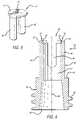
- FIG. 7is a side view in partial cross section of a male connector device in accordance with aspects of the invention aligned for connection with a female Luer connector showing the female connector device in cross section;
- FIG. 8is a side view in partial cross section of the male connector and female connector devices of FIG. 7 in which they are fully connected. The view also shows that the female connector device includes an inner engagement surface that is smaller in diameter than the male connector device to thereby contract the distal end of the male connector device and thereby activate the male connector device for fluid flow;
- FIG. 9is a side view in partial cross section of the male connector device of FIGS. 7 and 8 fully engaged with a female connector device having an internal valve mechanism in which the distal end of the male connector device has been contracted to thereby activate the male connector device for fluid flow;
- FIG. 10is an end-on view of the distal end of the male connector device when in the contracted configuration presenting one embodiment of a flow path created through the closure cap;
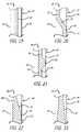
- FIG. 11is a perspective view of the distal end of a male connector device in accordance with aspects of the invention when the distal end is contracted due to connection with a smaller diameter female connector device and showing that as the diameter of the first end contracts, the diameter of the closure cap contracts and a center section of the closure cap containing the aperture is displaced in a longitudinal axial direction, in this case, it puckers axially outwards, thereby causing the aperture to open to permit fluid flow through the closure cap;
- FIG. 12is a perspective view of the distal end of a male connector device in accordance with aspects of the invention when the distal end is contracted due to connection with a smaller diameter female connector device and showing that as the diameter of the first end contracts, the diameter of the closure cap contracts and a center section of the closure cap containing the aperture is displaced in a longitudinal axial direction, in this case, it puckers axially inwards, thereby causing the aperture to open to permit fluid flow through the closure cap;
- FIGS. 13 through 18present radial cross-sectional views of different webbing configurations disposed between the relatively rigid walls of the male body member
- FIGS. 19 through 23present axial cross-sectional views of different webbing configurations disposed between the relatively rigid walls of the male body member
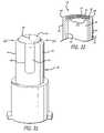
- FIG. 24is a perspective view of an alternate embodiment of an elongated male body having alternate wall segments of reduced thickness to enhance flexibility and permit collapsing the distal end when engaged with a female connector device;
- FIG. 25is an end-on view of the configuration of the wall of the male body portion of FIG. 24 with the closure cap removed so that the alternating segments of more rigid wall segments with more flexible wall segments can be seen;
- FIG. 26presents a side, cross-sectional view of the distal end of the male connector device showing a closure cap biased axially outward at its center in its natural configuration;
- FIG. 27presents a side, cross-sectional view of the distal end of the male connector device showing a closure cap biased axially inward at its center in its natural configuration;
- FIG. 28presents a side, cross-sectional view of the distal end of the male connector device of FIG. 2 in the contracted configuration showing the slit of the closure cap that was biased axially inward on one side and axially outward on the other side open for fluid flow;
- FIG. 29is an end-on view of a closure cap having two parallel and offset slits for fluid flow when opened;
- FIG. 30presents a side, cross-sectional view of the distal end of the male connector device of FIG. 2 having the closure cap of FIG. 29 in the contracted configuration showing the membrane material outside of the slits that were biased axially outward open and the central membrane between the slits that was biased axially inward also open for fluid flow;
- FIG. 30 apresents a cross section view of an embodiment of the angled slits that may be used in FIG. 30 . Due to the angle of the slits, resistance against internal pressure possibly causing the slits to open and permit undesired fluid flow is prevented;
- FIG. 31shows the male connector device of FIG. 2 with the slit in the closure cap rotated by ninety degrees to be parallel with relatively rigid wall segments;
- FIG. 32is an enlarged cross-sectional view of the distal end of the elongated male body showing a closure cap that is slightly bulged axially outward at its center with fillets between the flexible wall segments and the closure cap;
- FIG. 33shows an application of the male connector device in accordance with the invention with a syringe and showing the male body aligned with a female connector device for engagement;
- FIG. 34is a male connector device similar to FIG. 33 with a threaded collar surrounding the male body portion for more secure engagement with a female connector;
- FIG. 35shows an application of the male connector device in accordance with the invention with a blood collection device having a shield and sharpened cannula within the shield for use of blood collection tubes.
- FIG. 1a self-sealing male Luer connector device 30 in accordance with aspects of the present invention mounted on the distal end 31 of a syringe 32 and operatively connected to the proximal end of a patient IV fluid administration set 34 for the administration or withdrawal of fluids through an IV line.
- distalrefers to the direction toward the patient 33
- proximalrefers to the direction away from the patient, or toward the collection or dispensing device.
- the male connector devicehas an elongated male body portion 36 with a first or distal end 38 and a second or proximal end 40 .
- the male connector devicealso includes a flexible closure cap 42 that is disposed at the first end.
- the male body portionis formed with a plurality of relatively rigid wall segments 44 extending axially from a base 46 and terminating distally at the first end in rim elements 48 that cooperate to support the closure cap.
- the rim elementshave radiused or chamfered exterior distal edges 47 as shown more clearly in FIG. 3 to facilitate the insertion of the male connector device into a female Luer connector.
- relatively flexible wall segments 50that complete the tubular body and form an hermetic seal.
- the wall segments 44 and 50form a continuous tubular wall 52 from the distal end to the proximal end of the male body portion.
- the closure cap and the flexible wall segmentsare manufactured as one continuous piece by co-injection molding, but it is possible to manufacture the cap and the wall segments separately and bond them together.
- a conventional female Luer connector 56Disposed at the proximal or second end 40 of the male connector device 30 is a conventional female Luer connector 56 , though it will be appreciated that a variety of other connectors and devices, such as simply a tubing connection or a syringe, may be employed instead.
- the base 46is located between the distally-extending male body portion and the proximally-extending female Luer connector. The base provides a transition between the larger outer diameter of the female connector and the smaller diameter of the male body portion. In other embodiments where the proximal end of the male connector device is smaller in diameter that that shown for the female connector in FIG. 2 , the base may be the same diameter as the male body portion or may have an even different configuration.
- the female Luer connector endincludes standard external threads 58 , although in some applications, threads may not be necessary.
- the closure cap 42 of the self-sealing male connector device 30has a generally circular perimeter in this embodiment, corresponding to an opening formed at the distal end 38 of the male body portion 36 .
- the closure capis formed of a membrane that includes a resealable aperture 54 that is closed to form a seal against fluid flow when the body is in its natural or “at-rest” configuration as shown.
- the resealable apertureis a slit as shown in the figures. As is well known, a slit does not permit the passage of fluid in its natural or “at rest” configuration.
- the slitis oriented in regard to the relatively rigid wall segments 44 such that one end of the slit is adjacent one relatively rigid wall segment and the other end of the slit is adjacent an opposing relatively rigid wall segment.
- the relatively wall segmentsengage a smaller inner-diameter female connector and are forced to move toward each other, the ends of the slit will also be forced to move toward each other thus causing the slit to open.
- the closure cap 42is dimensioned to fit along a ridge 60 , best seen in FIG. 4 , formed in the rigid wall segments 44 at the distal end 38 .
- FIG. 4shows the ridge without the presence of the closure cap while
- FIG. 3shows a cross section view of the closure cap mounted in the male body portion 36 .
- FIG. 5presents a view of a flexible closure cap 42 that can be assembled at the distal end 38 of the rigid walls 44 of the male body portion 36 shown in FIG. 4 to form the assembled male Luer connector device 30 shown in FIG. 2 .
- the closure capincludes the top surface 62 having the slit 54 as well as the flexible wall segments 50 shown in FIG. 2 .
- the diameter of the top surfaceis selected to be the same as the opening in the ridge 60 shown in FIG. 4 . Because the resealable aperture 54 in the closure cap is a slit in this case, it remains closed to the flow of fluid when the closure cap is mounted to the male body portion. As discussed, an external force is required to open the slit and permit fluid flow.
- the closure capmay be somewhat undersized in relation to the distal end 38 with a small amount of stretching required to mount the cap in the ridge. The cap will therefore be under some degree of tension thereby holding the slit closed more strongly. Thus when in the configuration of FIG. 2 , the slit will resist the flow of fluid through it even more strongly.
- the male body portion 36 , the base 46 , and the proximal end 40may be considered to form the connector device housing 64 .
- the housingdefines a fluid flow passage 67 from its distal end 38 to its proximal end 40 .
- the relatively rigid wall segments 44are mounted to the base 46 in a cantilever manner as shown.
- the relatively rigid wall segmentshave notches 66 formed in them from their distal ends and extending in the proximal direction to a selected length. In this embodiment, the locations of the notches are selected so that two relatively rigid wall segments are opposite each other.
- the distal ends 38 of the opposing relatively rigid wall segmentsmay be moved toward one another when subjected to external pressure directed inward toward the longitudinal axis 68 of the housing.
- the opposing relatively rigid wall segmentstend to return to their natural at-rest configuration shown in FIG. 6 .
- This tendency to return to their natural configurationwill also return a closure cap 42 mounted at the distal end 38 to its natural at-rest configuration thereby closing the slit 54 in the cap, as shown in FIG. 2 .
- flexible wall segments 50have been included within the notches 66 , in this embodiment. In the one embodiment shown in FIG. 5 , those flexible wall segments are provided by portions of the closure cap.
- the male Luer connector device in accordance with aspects of the inventionis aligned with the opening of a first type of female Luer connector device 70 .
- the female Luer connector devicethere is no internal valve and the Luer opening 72 and channel is of the standard Luer taper and diameter.
- the female Luer openinghas a diameter D F1 that tapers down to a smaller diameter of D F2 in the distal direction. This opening diameter D F1 is equal to or larger than the diameter D M of the male connector device.
- the diameter D M of the male connector deviceis larger than the opening diameter D F1 of the female connector device.
- the chamfered, or otherwise rounded, edges 47 of the male connector devicewill assist in engaging the distal end 38 of the male connector device with the opening of the female connector device.
- the particular female Luer connector device shown in FIGS. 7 and 8does not include a valve at or near its opening.
- the female Luer connector device 74 of FIG. 9does include a valve, a portion of which is shown.
- the male Luer connector device 30has been fully engaged with the female connector device 70 so that the slit 54 of the male connector device has opened to permit fluid flow between the female and male connector devices.
- the distal end 38 of the male connector devicehas contracted as a result of its movement into the smaller diameter of the female Luer channel 72 .
- the relatively rigid wall segments 44 of the male connector devicehave been bent inwardly to the contracted configuration at which the slit 54 opens to permit the flow of fluid through the male connector device.
- the male Luer connector device 30 in accordance with aspects of the inventionhas been fully engaged with a different type of female connector device 74 .
- the female connector device of this figureincludes an internal valve mechanism 76 that automatically opens to permit flow through the female connector device when the valve mechanism has been displaced into the housing of the female connector device as is shown in FIG. 9 .
- the opening 78 of the second female connector devicehas a standard diameter so as to accept all standard Luer male connector devices; however, the standard Luer taper may or may not exist. In the configuration shown in FIG. 9 , the standard female Luer taper does not exist at the opening 78 of the female connector device.
- the male body portionincludes the relatively rigid wall segments 50 .
- the biasing effect of the elongated relatively rigid wall segments 44 of the male body portion 36forces the rim elements 48 radially outwardly again toward the natural or “at-rest” configuration as shown in FIG. 2 causing the slit 54 to return to its natural closed configuration thereby resealing the aperture of the closure cap and preventing the flow of fluid through the male connector device.
- the self-sealing male connector device of the present inventioncloses and prevents flow therethrough both before and after connection with a female connector, or the like, while it opens and allows flow during connection.
- the embodiment shown in FIG. 2includes only two parts, the housing 64 and the closure cap 42 .
- the male connector device 30may be made as one part through an injection molding process or other means.
- the male connector 30has been inserted into the female connector 70 to achieve an operational configuration and the distal end 38 of the male luer has contracted in diameter.
- the smaller inner diameter of the tapered female connector wallforces the rim elements 48 and rigid wall segments 44 to flex radially inwardly into the contracted configuration.
- the diameter of the male body portion 36 and the length of the notches 66are configured so that when the male connector is inserted within the female connector device to the point where the relatively rigid wall segments can flex no farther, the rigid and flexible wall segments 44 and 50 lay substantially flush against the inner female engagement surface 80 of the female connector device to achieve a generally surface-to-surface seal between the two connector devices.
- FIG. 10shows the overall shape of the opening created by compressing the slit such as by inserting the male connector device into the female connector 70 of FIG. 8 .
- the entire distal end of the male connector deviceis contracted resulting in the closure cap 42 either flexing axially outward as shown in FIG. 11 or flexing axially inward, as shown in FIG. 12 .
- the slitis more likely to assume the configuration shown in FIG.
- the slitis more likely to assume the configuration shown in FIG. 12 , i.e., an axially inward pucker.
- webor “webbing” is meant to mean the flexible material located between the relatively rigid wall segments 44 that interconnects the rigid segments, whether that interconnecting material is formed from the same material as the rigid walls or is added and attached in some way.
- the configuration of the male body portion 36 shown in FIGS. 2 , 3 , 4 , and 6is well-suited for the injection molding or co-injection molding manufacturing process.
- the bodymay be made in a relatively simple two-half mold cavity with a single linear core pull.
- the male body portion including the base 46 and the rigid wall segments 44may be formed from a variety of plastic materials such as polyethylene, polypropylene, polycarbonate, UHMW, PVC, ABS, acrylic, nylon, POM, and K-resin. It follows that a wide range of radial biasing forces exerted by the free ends of the relatively rigid wall segments can be achieved by simply changing the material selection and/or adjusting the wall thickness of the body.
- notch 66 sizes and configurationsmay also be employed without departing from the scope of the present invention.
- the connector to be formed on the proximal end 40 of the male body portionsuch as a conventional female Luer connector 56 , may also be formed in the same molding operation to yield a single, integral housing 64 .
- the flexible wall segments 50 and the closure cap 42may be formed of a single unitary construction in a molding or extrusion and die-cutting process and then installed on the male body portion 36 using a solvent bonding, ultrasonic welding, or other such assembly technique now known or later developed.
- the flexible wall segments 50 and closure cap 42may be formed directly on the male body portion in an over-molding process as is known in the art, or they may be formed separately.
- the flexible wall segments 50span and sealingly engage the respective notches 66 and the closure cap engages the ridge 60 shown in FIG. 4 so that it is flush with the rim elements 48 at the distal end 38 of the male body portion so as to make the tubular male body portion continuous and leak-proof about its complete circumference.
- the flexible wall segmentsare configured as thin-walled webs and along with the closure cap may be formed of several resilient materials such as thermoplastic elastomers, TPV, thermoplastic vulcanates, and thermoplastic silicone.
- FIGS. 13 through 23various configurations of webbing located in the slots 66 in the male body portion 36 are shown.
- the slots 66may extend for the length of the rigid wall segments 44 . That is, they may extend from the base 46 to the distal end 38 .
- FIG. 13there is shown a cross-sectional view of the male body portion at the distal end showing the relatively rigid wall segments and flexible wall segments in their natural configuration. That is, the male Luer connector device, of which they form a part, is not engaged with a female connector in this figure.
- FIG. 14presents a cross-sectional view of the same male body portion in which the same relatively rigid wall segments and flexible wall segments of FIG.
- the flexible wall segments 50are attached to the centers of the rigid wall segments 44 .
- the flexible wall segmentsare attached to alternate outer edges and inner edges of the rigid wall segments.
- the male Luer connector deviceis in its natural configuration not engaged (disengaged) with a female connector such as is shown in FIG. 7 .
- FIG. 16the same male body portion is contracted due to being engaged with a female Luer connector, such as in FIG. 8 .
- the flexible wall segmentsform an outer surface coextensive with the outer surface of the rigid wall segments so that the interface between the female and male connector devices will not leak.
- the flexible wall segment 50 in this embodimenthas a non-uniform thickness that includes a thicker, centrally-located, radially outward oriented protrusion or ridge 86 .
- the flexible wall segment 50is installed so as to span the notch 66 substantially at the inside portion 88 of its edges. In this way, as the male connector device 30 is compressed so as to close the notch, the flexible wall segment 50 b expands along its length radially outwardly so that the bend 80 is shifted radially outwardly and into contact with the inside surface of the female connector.
- By being pre-biased to fold or bend in a specific direction, here radially outwardlyit will be appreciated that the risk of the flexible wall segment 50 b buckling or flexing in an unwanted direction is minimized.
- the flexible wall segment 50is shown having a substantially uniform thickness along its length and is generally centered radially between the outside edge 90 and the inside edge 88 of the rigid wall segment 44 .
- FIG. 20the axial configuration of another embodiment of a flexible wall segment 50 is shown as having a distal upper portion 92 aligned with the inside edge 88 of the rigid wall segment 44 , a intermediate proximally-angled portion 94 , and a proximal lower portion 96 aligned with the outside edge 90 of the rigid wall segment. All of the flexible wall portions 92 , 94 , and 96 have a substantially uniform thickness.
- the flexible wall segmentis configured to have a radially inset upper portion corresponding to the distal end of the male body portion and adjacent the rim elements that serves to facilitate inward movement of the rim elements to the contracted configuration and ease insertion of the male connector into the female connector.
- the proximally-angled portion of the flexible wall segmentthen smoothly transitions the wall to the outside edge of the male body portion so as to provide more resiliency within the lower, proximal section of the notch and to cause the compression and resulting radial expansion of the flexible wall segment to contribute to sealing the male connector within the female connector.
- FIG. 21another embodiment of flexible wall segment 50 is shown in cross-section as having a substantially uniform lengthwise portion 98 generally centered between the outside edge 90 and the inside edge 88 with the exception of a radially outwardly projecting circumferential bulge 100 spaced proximally from the distal end 38 .
- the outer extremity of the bulgeis substantially aligned with the outside edge 90 .
- FIG. 22there is shown yet another embodiment of flexible wall segment 50 having a proximal lower portion 102 with a cross-sectional thickness that is slightly smaller than the wall thickness of the rigid wall segments 44 .
- a distal upper portion 104 of the flexible wall segmentis formed having a tapered outer surface so that the flexible wall segment becomes thinner toward the distal end 38 . In this way, the radially inset distal portion of the flexible wall segment facilitates compression of the distal end of the male body portion 36 .
- FIG. 23there is shown another embodiment of a flexible wall segment 50 having a lower proximal portion 106 and a distal upper portion 108 having tapered inner and outer surfaces so that the flexible wall segment becomes thinner toward the distal end 38 and terminates generally centered between the outside and inside edges 90 and 88 respectively.
- the distal taper of the present flexible wall segmentallows for easier compression of the distal end of the male body portion 36 toward the contracted configuration.
- the substantially symmetrical cross-section of the flexible wall segmentwill help ensure uniform compression and prevent unwanted buckling of the wall.
- FIG. 24there is shown another embodiment of the elongated male body portion 36 that has reduced thickness sections 50 interspaced with rigid wall segments 44 comprising the same material but thicker.
- the reduced thickness sections and thicker sectionsterminate at the base 46 as in other embodiments.
- all walls, both rigid and flexibleare of substantially uniform cross-sectional thickness at the base. This provides structural integrity at the proximal end of the tubular body.
- the reduced thickness sections 50 formed in the tubular male bodyprovide increased radial flexibility at its distal end 38 .
- the desired radial compressibilityis achieved so as to allow rim elements 48 at the distal end to flex radially inwardly upon insertion into a female connector.
- the outside surface of the male body portion 36has a continuous surface that helps provide surface-to-surface engagement with the inside surface of the female connector, thereby forming a tight seal during connection.
- a distal-end viewis shown in FIG. 25 .
- the elongated male body portion 36is formed with a tubular wall 44 that is substantially uniform in diameter and wall thickness along its entire length.
- the bodyis made of a compressible, resilient material such that the continuous distal rim 48 may be oversized as compared to the inner diameter of the female connector and be compressed radially inwardly toward the contracted configuration when inserted in the female connector.
- a materialas for example, medical grade thermoplastic rubber, is substantially resilient so as to return to its expanded configuration upon removal from the female connector, but also conforms to the inside surface of the female connector when inserted therein so as to maintain a positive seal between the engaged connectors.
- a mounting ridgewould be included at the distal end for receiving the closure cap shown in other figures, except that the closure cap will not have flexible wall segments formed as part of it.
- the elongated male body portion of the male connector deviceis formed with spaced-apart undulations to provide a reduced thickness cross-section about the body.
- the undulationscooperate to form flexible wall segments between the remaining relatively rigid wall segments, thereby allowing for radial compression of the overall tubular body during engagement with a female connector device.
- the undulationsterminate short of the base so that the base provides structural integrity and biasing of the reduced in thickness male body portion.
- FIG. 26there is shown a cross-sectional view of the male body portion 36 in its natural, at-rest, expanded configuration.
- the center 110 of the closure cap 42is configured to have a slightly axially outward bias or bow.
- the axially outward pre-bias of the closure capcauses the cap to further flex or bow axially outwardly into a convex configuration, as shown in FIG. 11 .
- FIG. 27there is shown an elongated male body portion 36 having an alternative embodiment closure cap 42 sealingly installed thereon.
- the closure capis again formed as being generally annular so as to be flush along the ridge 60 of the distal end 38 and has a single slit aperture 54 oriented to be generally parallel to the flexible wall segments 50 .
- the closure cap 42is formed having a slightly axially inward bias or bow at its center 112 .
- the axially inward pre-bias of the closure capcauses the cap 42 a to further bow axially inwardly into a concave configuration, as shown in FIG. 12 .
- the closure cap 42is generally planar when the male body portion 36 is in its natural, at-rest, expanded configuration, as shown in FIG. 2 .
- the resealable aperture or slit 54is formed in the cap so as to be generally parallel to the flexible wall segments 50 and to the direction of the radial compression forces indicated by the directional arrows 112 in FIG. 28 .
- the capis formed such that one side 114 is biased to flex axially outwardly upon compression, and the opposite side 116 of the cap is biased to flex axially inwardly upon compression.
- FIG. 29there is shown another alternative embodiment closure cap 118 installed on an elongated body 36 of the male connector device 30 .
- the alternative closure capis formed having two parallel, spaced-apart slits 120 and 122 again generally oriented to be parallel to the flexible wall segments 50 .
- the alternative closure capis essentially divided into two opposite sides with a central membrane 124 portion between the two sides.
- the alternative closure capis configured so as to be generally planar in its natural configuration. Then, as shown in FIG.
- the central portion 124 of the alternative closure cap 118will flex axially inwardly while the opposite sides 126 and 128 will flex axially outwardly to open the two slits 120 and 122 and create two flow paths therethrough.
- the thickness of the closure capmay be increased in the area of the central membrane portion 124 to further facilitate its flexing inwardly with respect to the opposite adjacent sides.
- FIG. 30 aprovides one embodiment where the slits 120 and 122 are formed at an angle so as to resist internal pressure from possibly causing undesired fluid flow through the slits. If internal pressure builds up against the center section 124 , movement of the center section to open will be resisted by the two outer sections 126 and 128 since each outer section has material overlapping the outer portion of the middle section due to the angled slits.
- the closure cap 42has a single slit 54 however when the cap is mounted to the male body 36 , the slit is oriented so that the ends of the slit are adjacent the flexible wall segments 50 and the slit is therefore generally perpendicular to the flexible wall segments 50 .
- the slitwill also then be generally perpendicular to the direction of the radial compression forces, as indicated by arrows 112 , exerted on the relatively rigid wall segments 44 when the male connector device 30 is inserted within a female connector device. Further, as shown in FIG.
- the center 130 of the closure capis configured to have a slightly axially outward bias or bow so that when the male body portion and the closure cap are radially compressed, the axially outward pre-bias of the closure cap causes the cap to further flex or bow axially outwardly into a convex configuration opening the slit.
- the compressionis perpendicular to the axis of the slit, as shown by the arrows 112 , the reduction in the annular perimeter of the body and of the closure cap as it is compressed results in the opening of the slit.
- the closure cap 42 having a slit aperture 54can be mounted such that the ends of the slit are located adjacent flexible wall segments 50 and will therefore be oriented generally perpendicular to the force on the rigid wall segments 44 , as shown in FIG. 31 .
- the center of the closure capis configured with a slightly axially inward bias or bow (similar to that shown in FIG. 27 ) so that when the male body portion 36 and the cap are radially compressed, the axially inward pre-bias causes the cap to further flex or bow axially inwardly into the concave configuration shown in FIG. 12 .
- the reduction in the annular perimeter of the body and the closure cap, as it is compressed,causes the inward displacement of the cap's center to open the slit.
- the closure caphas a slightly axially outward pre-biased flex but is mounted within the mounting ridge 60 .
- the flexible wall segments 50are positioned radially outwardly within each notch 66 and are configured at their distal ends with radially inwardly projecting fillets 132 adjoining the closure cap. Because the fillets interconnect the flexible wall segments and the closure cap, they provide added pressure to direct the closure cap axially outwardly as the flexible wall segments shift radially inwardly during engagement with a female connector device. The fillets therefore cooperate with the flexible wall segments to flex the closure cap toward its convex, dome-shaped configuration to thereby open the slit as shown in FIG. 11 .
- the reverse actiontakes place between the flexible wall segments 50 , the fillets 132 , and the closure cap 42 . That is, as the radial compression forces are removed from the male body 36 , the relatively rigid wall segments 44 , flexible wall segments 50 , and base 46 cooperate to flex the body back to its natural, expanded configuration. The flexible wall segments flex generally radially outwardly and return to their natural configuration. In so doing, the interconnecting fillet 132 serves to help direct the closure cap 42 back to its at-rest configuration shown in FIG. 32 .
- the radially-outward movement of the flexible wall segments during the return of the body to its natural, at-rest, expanded configurationalso increases the volume within the male connector device, thereby creating a small partial vacuum.
- This partial vacuumcreates a draw-back effect that can draw residual fluid on or about the resealable aperture 54 into the male connector as it reseals so as to further keep the fluid in a controlled manner and prevent exposure of the fluid to both care givers and patients.
- the closure cap 42can be biased axially inward and have fillets between the flexible wall segments and the closure cap.
- biased inwardsuch as is shown in FIG. 27
- the distal end 38 of the male connector device 30will take on the configuration shown in FIG. 12 when contracted due to engagement with a female connector device.
- the fillet interconnecting the distal ends of the respective flexible wall segments with the closure capthen serves to pull the closure cap inwardly to open the slit.
- FIG. 33there is shown a partial perspective view of and embodiment of the male connector device 30 in accordance with the present invention connected to a medical syringe 140 .
- the distal end 142 of the syringeis formed with a male Luer connector (not shown) configured to sealingly engage the female Luer connector 52 formed at the proximal end of the male connector device, and may be additionally configured with a collar 144 concentrically about the male Luer connector of the syringe and having internal threads (not shown) configured to threadably engage external thread portions (not shown) formed on the proximal base of the male connector device's female connector.
- the self-sealing closure cap 42prevents the escape of any fluid from the syringe while the connector device is disconnected and in its natural, at-rest, expanded configuration as shown.
- a female connector 70 of a patient's IV linein position for connection, as when a fluid in the syringe is to be administered to the patient or a fluid from the patient is to be withdrawn into the syringe.
- the female connector deviceincludes external thread elements 134
- the male connector devicein accordance with the present invention provides controlled dispensing from and withdrawal into a syringe or other such medical device or dispenser without the use of a sharpened needle. Further, it will be appreciated that the male connector device is easy to wipe and keep sanitary, as all engagement surfaces are exposed and easily accessible upon disconnection of the device from the female connector.
- FIG. 34shows the same male connector device 30 as in FIG. 33 except with the addition of a threaded collar 150 surrounding the male body 36 and having internal threads 152 .
- the collar's threadsare used for engaging the external thread segments 134 of the female connector 70 to firmly secure the male connector and female connector devices together.
- FIG. 35shows yet another alternative embodiment in which the male connector device 30 has a blood collection device 156 mounted opposite the base 46 from the male body portion 36 , rather than a conventional female Luer connector.
- the blood collection devicewhich is known and used in the art, comprises a cannula 158 having a sharpened tip 160 and is securely embedded in the cannula mount 162 .
- a shield 164is mounted about the needle to protect clinicians and patients from accidental needle sticks and to support a blood collection tube in some cases.
- the male body portion 36 of the connector device 30may be connected to a female connector device of a patient's IV line, as discussed above, to open the slit 54 in the closure cap and create a flow path between the patient's IV line and the blood collection 158 .
- the tubeis removed form the blood collection device 156 and the male body portion 36 may be disconnected from the female connector device.
- the male body portionexpands to its natural, at-rest configuration causing the slit 54 to reseal and trap all blood and any other fluids within the male connector device for safe disposal.
- the self-sealing, needle-free oversized male connectorserves to safely and easily connect to and disconnect from a female Luer connector of a patient's IV line for the effective and controlled administration and/or withdrawal of fluids.
Landscapes
- Health & Medical Sciences (AREA)
- Life Sciences & Earth Sciences (AREA)
- Heart & Thoracic Surgery (AREA)
- Public Health (AREA)
- Engineering & Computer Science (AREA)
- Veterinary Medicine (AREA)
- Biomedical Technology (AREA)
- Hematology (AREA)
- Animal Behavior & Ethology (AREA)
- General Health & Medical Sciences (AREA)
- Physics & Mathematics (AREA)
- Surgery (AREA)
- Molecular Biology (AREA)
- Biophysics (AREA)
- Pathology (AREA)
- Medical Informatics (AREA)
- Pulmonology (AREA)
- Anesthesiology (AREA)
- Infusion, Injection, And Reservoir Apparatuses (AREA)
- Connector Housings Or Holding Contact Members (AREA)
- Measurement Of The Respiration, Hearing Ability, Form, And Blood Characteristics Of Living Organisms (AREA)
- Details Of Garments (AREA)
- Details Of Connecting Devices For Male And Female Coupling (AREA)
- Earth Drilling (AREA)
Abstract
Description
Claims (20)
Priority Applications (17)
| Application Number | Priority Date | Filing Date | Title |
|---|---|---|---|
| US11/026,002US7651481B2 (en) | 2004-12-30 | 2004-12-30 | Self-sealing male connector device with collapsible body |
| AU2005323127AAU2005323127B2 (en) | 2004-12-30 | 2005-12-16 | Self-sealing male connector device with collapsible body |
| ES05854603TES2315945T3 (en) | 2004-12-30 | 2005-12-16 | SELF-MILLING MALE CONNECTOR DEVICE WITH FOLDING BODY. |
| NZ556694ANZ556694A (en) | 2004-12-30 | 2005-12-16 | Self-sealing male connector device wherein a slit valve opens when attached to the matching female connector |
| HK08103240.4AHK1109091B (en) | 2004-12-30 | 2005-12-16 | Self-sealing male connector device with collapsible body |
| DE602005011054TDE602005011054D1 (en) | 2004-12-30 | 2005-12-16 | SELF-CLOSING CONNECTOR DEVICE WITH COLLABORABLE BODY |
| JP2007549459AJP5086811B2 (en) | 2004-12-30 | 2005-12-16 | Self-sealing male connector device with foldable body |
| DK05854603TDK1835961T3 (en) | 2004-12-30 | 2005-12-16 | Self-closing male connector with collapsible body |
| PL05854603TPL1835961T3 (en) | 2004-12-30 | 2005-12-16 | Self-sealing male connector device with collapsible body |
| PT05854603TPT1835961E (en) | 2004-12-30 | 2005-12-16 | Self-sealing male connector device with collapsible body |
| EP05854603AEP1835961B1 (en) | 2004-12-30 | 2005-12-16 | Self-sealing male connector device with collapsible body |
| PCT/US2005/045924WO2006073778A1 (en) | 2004-12-30 | 2005-12-16 | Self-sealing male connector device with collapsible body |
| AT05854603TATE413901T1 (en) | 2004-12-30 | 2005-12-16 | SELF-LOCKING CONNECTOR DEVICE WITH COLLAPSIBLE BODY |
| CA2593373ACA2593373C (en) | 2004-12-30 | 2005-12-16 | Self-sealing male connector device with collapsible body |
| NO20073869ANO20073869L (en) | 2004-12-30 | 2007-07-24 | Self-sealing male coupling device with collapsible unit |
| ZA200706204AZA200706204B (en) | 2004-12-30 | 2007-07-26 | Self-sealing male connector device with collapsible body |
| CY20091100146TCY1108739T1 (en) | 2004-12-30 | 2009-02-09 | MEN'S AUTOMATIC AUTOMATED ASSEMBLING DEVICE WITH Foldable Body |
Applications Claiming Priority (1)
| Application Number | Priority Date | Filing Date | Title |
|---|---|---|---|
| US11/026,002US7651481B2 (en) | 2004-12-30 | 2004-12-30 | Self-sealing male connector device with collapsible body |
Publications (2)
| Publication Number | Publication Date |
|---|---|
| US20060149213A1 US20060149213A1 (en) | 2006-07-06 |
| US7651481B2true US7651481B2 (en) | 2010-01-26 |
Family
ID=36218076
Family Applications (1)
| Application Number | Title | Priority Date | Filing Date |
|---|---|---|---|
| US11/026,002Active2026-11-30US7651481B2 (en) | 2004-12-30 | 2004-12-30 | Self-sealing male connector device with collapsible body |
Country Status (16)
| Country | Link |
|---|---|
| US (1) | US7651481B2 (en) |
| EP (1) | EP1835961B1 (en) |
| JP (1) | JP5086811B2 (en) |
| AT (1) | ATE413901T1 (en) |
| AU (1) | AU2005323127B2 (en) |
| CA (1) | CA2593373C (en) |
| CY (1) | CY1108739T1 (en) |
| DE (1) | DE602005011054D1 (en) |
| DK (1) | DK1835961T3 (en) |
| ES (1) | ES2315945T3 (en) |
| NO (1) | NO20073869L (en) |
| NZ (1) | NZ556694A (en) |
| PL (1) | PL1835961T3 (en) |
| PT (1) | PT1835961E (en) |
| WO (1) | WO2006073778A1 (en) |
| ZA (1) | ZA200706204B (en) |
Cited By (58)
| Publication number | Priority date | Publication date | Assignee | Title |
|---|---|---|---|---|
| US20100174242A1 (en)* | 2008-12-19 | 2010-07-08 | Harold Anderson | Medical connector with closeable luer connector |
| US20110015581A1 (en)* | 2005-07-06 | 2011-01-20 | Icu Medical, Inc. | Medical connector with closeable male luer |
| US20110208128A1 (en)* | 2010-02-24 | 2011-08-25 | Becton, Dickinson And Company | Safety Drug Delivery Connectors |
| US20110208160A1 (en)* | 2010-02-24 | 2011-08-25 | Becton, Dickinson And Company | Safety Drug Delivery System |
| WO2011146764A1 (en)* | 2010-05-19 | 2011-11-24 | Tangent Medical Technologies Llc | Integrated vascular delivery system with safety needle |
| US8066692B2 (en) | 2003-12-30 | 2011-11-29 | Icu Medical, Inc. | Medical male luer connector with increased closing volume |
| US8414554B2 (en) | 2008-05-14 | 2013-04-09 | J & J Solutions, Inc. | Systems and methods for safe medicament transport |
| US8465461B2 (en) | 2010-07-27 | 2013-06-18 | Becton, Dickinson And Company | Blunt needle safety drug delivery system |
| US8486024B2 (en) | 2011-04-27 | 2013-07-16 | Covidien Lp | Safety IV catheter assemblies |
| US8628516B2 (en) | 2009-03-22 | 2014-01-14 | Elcam Medical Agricultural Cooperative Association Ltd. | Closed male luer connector |
| US8628497B2 (en) | 2011-09-26 | 2014-01-14 | Covidien Lp | Safety catheter |
| US8647310B2 (en) | 2010-05-06 | 2014-02-11 | Icu Medical, Inc. | Medical connector with closeable luer connector |
| US8715250B2 (en) | 2011-09-26 | 2014-05-06 | Covidien Lp | Safety catheter and needle assembly |
| US8758306B2 (en) | 2010-05-17 | 2014-06-24 | Icu Medical, Inc. | Medical connectors and methods of use |
| US8771230B2 (en) | 2010-05-19 | 2014-07-08 | Tangent Medical Technologies, Llc | Integrated vascular delivery system |
| US8814833B2 (en) | 2010-05-19 | 2014-08-26 | Tangent Medical Technologies Llc | Safety needle system operable with a medical device |
| US8834422B2 (en) | 2011-10-14 | 2014-09-16 | Covidien Lp | Vascular access assembly and safety device |
| US8870850B2 (en) | 2000-07-11 | 2014-10-28 | Icu Medical, Inc. | Medical connector |
| US8939938B2 (en) | 2006-10-12 | 2015-01-27 | Covidien Lp | Needle tip protector |
| US9107809B2 (en) | 2010-05-27 | 2015-08-18 | J & J Solutions, Inc. | Closed fluid transfer system |
| US9114242B2 (en) | 2005-07-06 | 2015-08-25 | Icu Medical, Inc. | Medical connector |
| US9168366B2 (en) | 2008-12-19 | 2015-10-27 | Icu Medical, Inc. | Medical connector with closeable luer connector |
| US9186707B2 (en) | 2007-04-02 | 2015-11-17 | C. R. Bard, Inc. | Insert for a microbial scrubbing device |
| US9192449B2 (en) | 2007-04-02 | 2015-11-24 | C. R. Bard, Inc. | Medical component scrubbing device with detachable cap |
| US9278206B2 (en) | 2009-03-25 | 2016-03-08 | Icu Medical, Inc. | Medical connectors and methods of use |
| US9433768B2 (en) | 2011-03-25 | 2016-09-06 | Becton, Dickinson And Company | Drug delivery connectors |
| US9592366B2 (en) | 2009-08-14 | 2017-03-14 | The Regents Of The University Of Michigan | Integrated vascular delivery system |
| USD786427S1 (en) | 2014-12-03 | 2017-05-09 | Icu Medical, Inc. | Fluid manifold |
| USD793551S1 (en) | 2014-12-03 | 2017-08-01 | Icu Medical, Inc. | Fluid manifold |
| US9775981B2 (en) | 2013-03-15 | 2017-10-03 | Icu Medical, Inc. | Medical connector |
| US9814870B2 (en) | 2010-08-17 | 2017-11-14 | Becton, Dickinson And Company | Non-luer connectors |
| US9877895B2 (en) | 2013-08-02 | 2018-01-30 | J&J Solutions, Inc. | Compounding systems and methods for safe medicament transport |
| US9884176B2 (en) | 2004-11-05 | 2018-02-06 | Icu Medical, Inc. | Medical connector |
| US9933094B2 (en) | 2011-09-09 | 2018-04-03 | Icu Medical, Inc. | Medical connectors with fluid-resistant mating interfaces |
| US20180192933A1 (en)* | 2017-01-12 | 2018-07-12 | Biotechnology Institute, I Mas D, S.L. | Container device for collecting, storing and processing blood or a blood compound |
| US10086170B2 (en) | 2014-02-04 | 2018-10-02 | Icu Medical, Inc. | Self-priming systems and methods |
| US10322275B2 (en) | 2015-10-30 | 2019-06-18 | ECMOtek, LLC | Devices for endovascular access through extracorporeal life support circuits |
| US10369349B2 (en) | 2013-12-11 | 2019-08-06 | Icu Medical, Inc. | Medical fluid manifold |
| US10695550B2 (en) | 2011-05-20 | 2020-06-30 | Excelsior Medical Corporation | Caps for needleless connectors |
| US10744316B2 (en) | 2016-10-14 | 2020-08-18 | Icu Medical, Inc. | Sanitizing caps for medical connectors |
| US10821278B2 (en) | 2014-05-02 | 2020-11-03 | Excelsior Medical Corporation | Strip package for antiseptic cap |
| US10888496B2 (en) | 2015-09-17 | 2021-01-12 | Corvida Medical, Inc. | Medicament vial assembly |
| US10894317B2 (en) | 2015-10-13 | 2021-01-19 | Corvida Medical, Inc. | Automated compounding equipment for closed fluid transfer system |
| US11351353B2 (en) | 2008-10-27 | 2022-06-07 | Icu Medical, Inc. | Packaging container for antimicrobial caps |
| US11389634B2 (en) | 2011-07-12 | 2022-07-19 | Icu Medical, Inc. | Device for delivery of antimicrobial agent into trans-dermal catheter |
| US11400195B2 (en) | 2018-11-07 | 2022-08-02 | Icu Medical, Inc. | Peritoneal dialysis transfer set with antimicrobial properties |
| US11433215B2 (en) | 2018-11-21 | 2022-09-06 | Icu Medical, Inc. | Antimicrobial device comprising a cap with ring and insert |
| US11517733B2 (en) | 2017-05-01 | 2022-12-06 | Icu Medical, Inc. | Medical fluid connectors and methods for providing additives in medical fluid lines |
| US11517732B2 (en) | 2018-11-07 | 2022-12-06 | Icu Medical, Inc. | Syringe with antimicrobial properties |
| US11534595B2 (en) | 2018-11-07 | 2022-12-27 | Icu Medical, Inc. | Device for delivering an antimicrobial composition into an infusion device |
| US11541220B2 (en) | 2018-11-07 | 2023-01-03 | Icu Medical, Inc. | Needleless connector with antimicrobial properties |
| US11541221B2 (en) | 2018-11-07 | 2023-01-03 | Icu Medical, Inc. | Tubing set with antimicrobial properties |
| US11559467B2 (en) | 2015-05-08 | 2023-01-24 | Icu Medical, Inc. | Medical connectors configured to receive emitters of therapeutic agents |
| US11684720B2 (en) | 2006-06-22 | 2023-06-27 | Excelsior Medical Corporation | Antiseptic cap that releases a gas such as nitric oxide |
| USD1003434S1 (en) | 2010-03-23 | 2023-10-31 | Icu Medical, Inc. | Medical connector seal |
| US11944776B2 (en) | 2020-12-07 | 2024-04-02 | Icu Medical, Inc. | Peritoneal dialysis caps, systems and methods |
| USRE50347E1 (en) | 2015-10-30 | 2025-03-25 | ECMOtek, LLC | Devices for endovascular access through extracorporeal life support circuits |
| US12440661B2 (en) | 2022-05-18 | 2025-10-14 | Icu Medical, Inc. | Medical fluid transfer device |
Families Citing this family (27)
| Publication number | Priority date | Publication date | Assignee | Title |
|---|---|---|---|---|
| US7651481B2 (en)* | 2004-12-30 | 2010-01-26 | CareFusion 303 Inc. | Self-sealing male connector device with collapsible body |
| US7981090B2 (en) | 2006-10-18 | 2011-07-19 | Baxter International Inc. | Luer activated device |
| US8221363B2 (en) | 2006-10-18 | 2012-07-17 | Baxter Healthcare S.A. | Luer activated device with valve element under tension |
| US7753338B2 (en) | 2006-10-23 | 2010-07-13 | Baxter International Inc. | Luer activated device with minimal fluid displacement |
| US20090306545A1 (en)* | 2008-06-09 | 2009-12-10 | Mamdouh Elsakka | Bronchoalveolar lavage catheter assembly |
| US20090306544A1 (en)* | 2008-06-09 | 2009-12-10 | Ho-Kin Ng | Instillation/aspiration device |
| US20090301480A1 (en)* | 2008-06-09 | 2009-12-10 | Mamdouh Elsakka | Diagnostic sample collection system and method of use |
| PL2138202T3 (en)* | 2008-06-23 | 2010-09-30 | Logica Medizintechnik Gmbh | Connecting part for connecting with a standardised luer lock connection |
| US9388929B2 (en) | 2009-12-09 | 2016-07-12 | Nordson Corporation | Male bayonet connector |
| US10711930B2 (en) | 2009-12-09 | 2020-07-14 | Nordson Corporation | Releasable connection assembly |
| USD783815S1 (en) | 2009-12-09 | 2017-04-11 | General Electric Company | Male dual lumen bayonet connector |
| JP5814257B2 (en) | 2009-12-23 | 2015-11-17 | ノードソン コーポレーションNordson Corporation | Button latch with integrally molded cantilever spring |
| MY159166A (en) | 2009-12-23 | 2016-12-30 | Nordson Corp | Fluid connector latches with profile lead-ins |
| AT508386B1 (en)* | 2010-02-10 | 2011-01-15 | Ke Kelit Kunststoffwerk Gmbh | DEVICE FOR CONNECTING WATER PIPES |
| US8974437B2 (en)* | 2011-07-28 | 2015-03-10 | Applied Medical Technology, Inc. | Coupling for medical fluids |
| FR2978353B1 (en)* | 2011-07-29 | 2013-08-02 | Vygon | ANTI-DROP DIRECT FLOW CONNECTORS WITH SECURE LATCHING |
| ITTO20120601A1 (en)* | 2012-07-09 | 2014-01-10 | Borla Ind | FLOW COMPONENT FOR MEDICAL LINES |
| BR112018010756B1 (en)* | 2015-11-25 | 2022-12-06 | Bayer Healthcare Llc | SYRINGE FILLING ADAPTER AND FLUID TRANSFER ASSEMBLY WITH SAID ADAPTER |
| USD838366S1 (en) | 2016-10-31 | 2019-01-15 | Nordson Corporation | Blood pressure connector |
| CR20220394A (en) | 2020-02-21 | 2023-01-23 | Bayer Healthcare Llc | Fluid path connectors for medical fluid delivery |
| PT4110452T (en) | 2020-02-28 | 2025-01-14 | Bayer Healthcare Llc | FLUID MIXING SET |
| WO2021188460A1 (en) | 2020-03-16 | 2021-09-23 | Bayer Healthcare Llc | Stopcock apparatus for angiography injector fluid paths |
| CN115697435A (en) | 2020-06-18 | 2023-02-03 | 拜耳医药保健有限责任公司 | Inline Bubble Suspension Device for the Fluid Path of Angiography Injectors |
| RS66861B1 (en) | 2020-08-11 | 2025-06-30 | Bayer Healthcare Llc | Features for angiography syringe |
| CN116547022A (en) | 2020-12-01 | 2023-08-04 | 拜耳医药保健有限责任公司 | Cassette for holding fluid path components of a fluid injector system |
| WO2022265695A1 (en) | 2021-06-17 | 2022-12-22 | Bayer Healthcare Llc | System and method for detecting fluid type in tubing for fluid injector apparatus |
| US20240172975A1 (en)* | 2022-11-29 | 2024-05-30 | Becton, Dickinson And Company | Flexible Capillary Tube with Integrated Luer Cap |
Citations (133)
| Publication number | Priority date | Publication date | Assignee | Title |
|---|---|---|---|---|
| US2931668A (en) | 1956-04-30 | 1960-04-05 | Bastian Blessing Co | Coupling |
| US2968497A (en) | 1958-02-05 | 1961-01-17 | Avro Aircraft Ltd | Self-sealing coupling |
| US3127892A (en) | 1960-07-13 | 1964-04-07 | Baxter Laboratories Inc | Blood handling apparatus |
| US3304047A (en) | 1964-05-22 | 1967-02-14 | Acf Ind Inc | Carburetor |
| US3334860A (en) | 1964-07-13 | 1967-08-08 | Jr Cecil G Bolton | Fluid coupling |
| US3986508A (en) | 1973-08-22 | 1976-10-19 | Abcor, Inc. | Sterilizable, medical connector for blood processing |
| US4066067A (en) | 1975-03-21 | 1978-01-03 | Dematex Development & Investment Establishment | Vial stopper for blood sampling device |
| US4080965A (en) | 1976-09-30 | 1978-03-28 | Baxter Travenol Laboratories, Inc. | In-line cannula valve assembly |
| US4121585A (en) | 1977-01-24 | 1978-10-24 | Becker Jr Karl E | Anti backflow injection device |
| US4133441A (en) | 1978-03-23 | 1979-01-09 | Baxter Travenol Laboratories, Inc. | Injection site |
| US4195632A (en) | 1978-05-03 | 1980-04-01 | Cutter Laboratories, Inc. | Fluid flow valve |
| US4233982A (en) | 1977-11-24 | 1980-11-18 | Richard Wolf Gmbh | Trocar sleeves having a ball valve |
| US4245635A (en) | 1979-01-29 | 1981-01-20 | Jelco Laboratories | Catheter assembly for intermittent intravenous use |
| US4326569A (en)* | 1980-02-15 | 1982-04-27 | Critikon, Inc. | Stopcock seal |
| US4340049A (en) | 1979-10-18 | 1982-07-20 | Baxter Travenol Laboratories, Inc. | Breakaway valve |
| US4379458A (en) | 1977-11-24 | 1983-04-12 | Richard Wolf Gmbh | Trocar sleeves having a ball valve |
| US4387879A (en) | 1978-04-19 | 1983-06-14 | Eduard Fresenius Chemisch Pharmazeutische Industrie Kg | Self-sealing connector for use with plastic cannulas and vessel catheters |
| US4397442A (en) | 1981-01-09 | 1983-08-09 | Abbott Laboratories | In-line sleeve valve |
| US4457749A (en) | 1982-04-19 | 1984-07-03 | Baxter Travenol Laboratories, Inc. | Shield for connectors |
| US4511359A (en) | 1982-09-29 | 1985-04-16 | Manresa, Inc. | Sterile connection device |
| US4623332A (en) | 1982-05-27 | 1986-11-18 | Patents Unlimited Ltd. | Needleless jet injector |
| US4662878A (en) | 1985-11-13 | 1987-05-05 | Patents Unlimited Ltd. | Medicine vial adaptor for needleless injector |
| US4723603A (en) | 1987-02-03 | 1988-02-09 | Marathon Oil Company | Preventing plugging by insoluble salts in a hydrocarbon-bearing formation and associated production wells |
| US4774965A (en) | 1987-07-01 | 1988-10-04 | Becton Dickinson And Co., Inc. | Material layer volume determination with correction band |
| US4774964A (en) | 1987-11-18 | 1988-10-04 | Applied Plastics Technology, Inc. | Disposable blood collection device |
| US4781702A (en) | 1986-06-20 | 1988-11-01 | Contempo Products, P. Herrli | Three-way connector for liquid exchange |
| US4816024A (en) | 1987-04-13 | 1989-03-28 | Icu Medical, Inc. | Medical device |
| US4834271A (en) | 1986-08-04 | 1989-05-30 | Litwin Walter J | One-piece dispensing closure |
| US4862913A (en) | 1987-07-09 | 1989-09-05 | Dieter Wildfang Kg | Check valve |
| US4915687A (en) | 1989-02-17 | 1990-04-10 | Sivert George A | Needleless injection port arrangement |
| US4917669A (en) | 1989-02-08 | 1990-04-17 | Safetyject | Catheter inserter |
| US4935010A (en) | 1986-11-20 | 1990-06-19 | Pharmacia Limited | Devices for sampling, drainage or infusion of liquids from or to the human or animal body |
| US4950260A (en) | 1989-11-02 | 1990-08-21 | Safetyject | Medical connector |
| US5006114A (en) | 1990-04-20 | 1991-04-09 | Rogers Bobby E | Medical valve assembly |
| US5065783A (en) | 1990-09-20 | 1991-11-19 | George Braddock Ogle, II | Valve with self-sealing internal cannula |
| US5070885A (en) | 1990-06-11 | 1991-12-10 | Care Medical Devices, Inc. | Disposable blood collection device |
| US5098385A (en) | 1990-04-26 | 1992-03-24 | Baxter International Inc. | Two-way valve for infusion devices |
| US5108376A (en) | 1990-11-14 | 1992-04-28 | Safetyject | Retractable intravenous needle assembly |
| US5122123A (en) | 1991-01-30 | 1992-06-16 | Vaillancourt Vincent L | Closed system connector assembly |
| US5139483A (en) | 1990-05-07 | 1992-08-18 | Ryan Medical, Inc. | Medical intravenous administration line connector |
| US5147333A (en) | 1991-05-13 | 1992-09-15 | Burron Medical Inc. | Needleless injection port with automatic backcheck valve |
| US5154703A (en) | 1990-10-30 | 1992-10-13 | Care Medical Devices, Inc. | Bloodless catheter |
| US5199948A (en) | 1991-05-02 | 1993-04-06 | Mcgaw, Inc. | Needleless valve |
| US5201725A (en) | 1991-09-26 | 1993-04-13 | Ivac | Needle free i.v. adapter |
| USRE34223E (en) | 1989-02-08 | 1993-04-13 | Care Medical Devices, Inc. | Catheter inserter |
| US5203775A (en) | 1990-09-18 | 1993-04-20 | Medex, Inc. | Needleless connector sample site |
| US5211634A (en) | 1991-08-06 | 1993-05-18 | Vaillancourt Vincent L | Composite seal structure and a coupling arrangement for a cannula |
| US5215537A (en) | 1990-09-13 | 1993-06-01 | Lynn Lawrence A | Septum for a blunt cannula |
| US5215538A (en) | 1992-02-05 | 1993-06-01 | Abbott Laboratories | Connector-activated in-line valve |
| US5242393A (en) | 1992-06-18 | 1993-09-07 | Becton, Dickinson And Company | Valved blunt cannula injection site |
| US5251873A (en) | 1992-06-04 | 1993-10-12 | Vernay Laboratories, Inc. | Medical coupling site |
| US5269771A (en) | 1993-02-24 | 1993-12-14 | Thomas Medical Products, Inc. | Needleless introducer with hemostatic valve |
| US5273533A (en) | 1992-03-11 | 1993-12-28 | Care Medical Products, Inc. | Medical valve |
| US5279571A (en) | 1991-12-30 | 1994-01-18 | Abbott Laboratories | Access site for fluid delivery system |
| US5281206A (en) | 1983-01-24 | 1994-01-25 | Icu Medical, Inc. | Needle connector with rotatable collar |
| US5284475A (en) | 1992-07-21 | 1994-02-08 | Mackal Glenn H | Luer valve adapter with expandable end |
| US5330450A (en) | 1983-01-24 | 1994-07-19 | Icu Medical, Inc. | Medical connector |
| US5334159A (en) | 1992-03-30 | 1994-08-02 | Symbiosis Corporation | Thoracentesis needle assembly utilizing check valve |
| US5344414A (en) | 1983-01-24 | 1994-09-06 | Icu Medical Inc. | Medical connector |
| US5360413A (en) | 1991-12-06 | 1994-11-01 | Filtertek, Inc. | Needleless access device |
| US5370636A (en) | 1992-08-28 | 1994-12-06 | Siemens Aktiengesellschaft | Plug-type connector for producing and interrupting a liquid flow connection |
| US5380306A (en) | 1991-11-25 | 1995-01-10 | Vygon | Unitary composite connector for a liquid circuit, in particular for medical applications |
| US5385372A (en) | 1993-01-08 | 1995-01-31 | Utterberg; David S. | Luer connector with integral closure |
| US5390898A (en) | 1994-04-06 | 1995-02-21 | Habley Medical Technology Corporation | Needleless dual direction check valve |
| US5395348A (en) | 1993-05-04 | 1995-03-07 | Symbiosis Corporation | Medical intravenous administration line connectors |
| US5395352A (en)* | 1992-02-24 | 1995-03-07 | Scimed Lift Systems, Inc. | Y-adaptor manifold with pinch valve for an intravascular catheter |
| US5397314A (en) | 1992-10-09 | 1995-03-14 | Farley; Kevin | Surgical cannula with ball valve |
| US5400500A (en) | 1992-07-29 | 1995-03-28 | Minnesota Mining And Manufacturing Company | Apparatus for making an injection or sampling site |
| US5401245A (en) | 1993-11-26 | 1995-03-28 | Haining; Michael L. | Medical connector with valve |
| US5405331A (en) | 1992-07-29 | 1995-04-11 | Minnesota Mining And Manufacturing Company | IV injection site and system |
| US5405333A (en) | 1992-12-28 | 1995-04-11 | Richmond; Frank M. | Liquid medicament bag with needleless connector fitting using boat assembly |
| US5405323A (en) | 1994-02-22 | 1995-04-11 | Aeroquip Corporation | Catheter check valve assembly |
| US5411499A (en) | 1988-01-25 | 1995-05-02 | Baxter International Inc. | Needleless vial access device |
| US5417673A (en) | 1993-01-13 | 1995-05-23 | Medex, Inc. | Whole blood sample needleless sample site |
| US5423791A (en) | 1992-03-31 | 1995-06-13 | Bartlett; J. Mark | Valve device for medical fluid transfer |
| US5425465A (en) | 1993-03-03 | 1995-06-20 | Healy; Patrick M. | Valved medication container |
| US5433330A (en) | 1992-08-07 | 1995-07-18 | The West Company, Incorporated | Needleless access stopper |
| US5439451A (en) | 1994-03-22 | 1995-08-08 | B. Braun Medical, Inc. | Capless medical backcheck valve |
| US5441487A (en) | 1993-11-30 | 1995-08-15 | Medex, Inc. | Plastic needleless valve housing for standard male luer locks |
| US5456668A (en) | 1994-01-14 | 1995-10-10 | F. H. Faulding & Co. Limited | Retractable venipuncture catheter needle and receptacle |
| US5456675A (en) | 1993-04-08 | 1995-10-10 | Fresenius Ag | Port cannula arrangement for connection to a port |
| US5464399A (en) | 1992-02-18 | 1995-11-07 | St. Francis Research Institute | Needleless intravenous infusion system |
| US5470327A (en) | 1993-06-29 | 1995-11-28 | Abbott Laboratories | Pointed adapter for blunt entry device |
| US5470319A (en) | 1994-06-20 | 1995-11-28 | Critical Device Corporation | Needleless injection site |
| US5480393A (en) | 1993-07-02 | 1996-01-02 | Bommarito; Alexander A. | Needle free access adapter |
| US5492147A (en) | 1995-01-17 | 1996-02-20 | Aeroquip Corporation | Dry break coupling |
| US5501426A (en) | 1992-06-04 | 1996-03-26 | Vernay Laboratories, Inc. | Medical coupling site valve body |
| US5514117A (en) | 1988-09-06 | 1996-05-07 | Lynn; Lawrence A. | Connector having a medical cannula |
| US5518026A (en) | 1994-09-30 | 1996-05-21 | G. T. Products, Inc. | Filler neck butterfly check valve |
| US5520665A (en) | 1992-09-07 | 1996-05-28 | Bespak Plc | Connecting apparatus for medical conduits |
| US5533983A (en) | 1993-11-26 | 1996-07-09 | Haining; Michael L. | Valved medical connector |
| US5533708A (en) | 1992-06-04 | 1996-07-09 | Vernay Laboratories, Inc. | Medical coupling site valve body |
| US5540661A (en) | 1994-05-03 | 1996-07-30 | Medex, Inc. | Needleless valve having a covalently bonded lubricious coating |
| US5549577A (en) | 1993-12-29 | 1996-08-27 | Ivac Corporation | Needleless connector |
| US5549651A (en) | 1994-05-25 | 1996-08-27 | Lynn; Lawrence A. | Luer-receiving medical valve and fluid transfer method |
| US5549566A (en) | 1994-10-27 | 1996-08-27 | Abbott Laboratories | Valved intravenous fluid line infusion device |
| US5552118A (en) | 1994-07-22 | 1996-09-03 | Critical Device Corporation | Needleless vacuum container port system |
| US5555908A (en) | 1995-06-23 | 1996-09-17 | Becton, Dickinson And Company | Valved PRN adapter for medical access devices |
| US5569235A (en) | 1994-06-21 | 1996-10-29 | Modern Medical Devices | Valve and valved container for use with a syringe fitting |
| US5573516A (en) | 1995-09-18 | 1996-11-12 | Medical Connexions, Inc. | Needleless connector |
| US5575769A (en) | 1995-05-30 | 1996-11-19 | Vaillancourt; Vincent L. | Cannula for a slit septum and a lock arrangement therefore |
| US5578059A (en) | 1993-11-30 | 1996-11-26 | Medex, Inc. | Anti-reflux valve with environmental barrier |
| US5584819A (en) | 1995-03-13 | 1996-12-17 | Kopfer; Rudolph J. | Nested blunt/sharp injection assembly |
| US5616130A (en) | 1994-06-20 | 1997-04-01 | Nima Enterprises, Inc. | Needleless injection site |
| US5674206A (en) | 1996-07-19 | 1997-10-07 | Benlan Inc. | Intravenous injection site having wipeable septum and valve structure |
| US5676346A (en) | 1995-05-16 | 1997-10-14 | Ivac Holdings, Inc. | Needleless connector valve |
| US5685866A (en) | 1991-12-18 | 1997-11-11 | Icu Medical, Inc. | Medical valve and method of use |
| US5738144A (en) | 1996-10-11 | 1998-04-14 | Aeroquip Corporation | Luer connecting coupling |
| US5782816A (en) | 1995-09-07 | 1998-07-21 | David R. Kipp | Bi-directional valve and method of using same |
| US5806831A (en) | 1993-10-13 | 1998-09-15 | Paradis; Joseph R. | Control of fluid flow with internal cannula |
| US5820601A (en) | 1994-06-20 | 1998-10-13 | Critical Device Corporation | Needleless injection site |
| US5839715A (en) | 1995-05-16 | 1998-11-24 | Alaris Medical Systems, Inc. | Medical adapter having needleless valve and sharpened cannula |
| US5848994A (en) | 1993-07-28 | 1998-12-15 | Richmond; Frank M. | IV sets with needleless spikeless fittings and valves |
| US6029946A (en) | 1997-09-15 | 2000-02-29 | Tiva Medical Inc. | Needleless valve |
| US6050978A (en) | 1997-05-09 | 2000-04-18 | Becton Dickinson And Company | Needleless valve connector |
| US6068011A (en) | 1993-10-13 | 2000-05-30 | Paradis; Joseph R. | Control of fluid flow |
| US6079432A (en) | 1996-07-02 | 2000-06-27 | Paradis; Joseph R. | Control of fluid flow by oval shaped valve member containing a cam interface |
| US6106502A (en) | 1996-12-18 | 2000-08-22 | Richmond; Frank M. | IV sets with needleless fittings and valves |
| US6113068A (en) | 1998-10-05 | 2000-09-05 | Rymed Technologies | Swabbable needleless injection port system having low reflux |
| US6206860B1 (en) | 1993-07-28 | 2001-03-27 | Frank M. Richmond | Spikeless connection and drip chamber with valve |
| US6299132B1 (en) | 1999-03-31 | 2001-10-09 | Halkey-Roberts Corporation | Reflux valve |
| US6344033B1 (en)* | 1997-05-20 | 2002-02-05 | Baxter International, Inc. | Needleless connector |
| US6485472B1 (en) | 1998-03-12 | 2002-11-26 | Frank M. Richmond | Spikeless connection and drip chamber with valve |
| US20030032940A1 (en) | 2001-08-10 | 2003-02-13 | Doyle Mark C. | Valved male luer |
| US20030060779A1 (en) | 1996-12-18 | 2003-03-27 | Richmond Frank M. | Spikeless connection and drip chamber with valve |
| US20030060804A1 (en) | 2001-09-06 | 2003-03-27 | Vaillancourt Vincent L. | Closed system connector assembly |
| US20030136932A1 (en) | 2001-08-10 | 2003-07-24 | Doyle Mark C. | Valved male luer |
| US20040006330A1 (en)* | 2000-07-11 | 2004-01-08 | Fangrow Thomas F | Medical valve with positive flow characteristics |
| US20040124389A1 (en) | 2002-12-31 | 2004-07-01 | Phillips John C. | Self-sealing male luer connector with biased valve plug |
| US7037303B2 (en)* | 2001-07-06 | 2006-05-02 | Opticon Medical, Inc. | Urinary flow control valve |
| US7040598B2 (en)* | 2003-05-14 | 2006-05-09 | Cardinal Health 303, Inc. | Self-sealing male connector |
| US20060149213A1 (en)* | 2004-12-30 | 2006-07-06 | John Raybuck | Self-sealing male connector device with collapsible body |
| US7118560B2 (en)* | 2003-02-28 | 2006-10-10 | Creative Plastic Technology, Llc | Needleless Luer activated medical connector |
Family Cites Families (2)
| Publication number | Priority date | Publication date | Assignee | Title |
|---|---|---|---|---|
| EP0949319A3 (en)* | 1998-04-08 | 2001-03-21 | Nippon Mitsubishi Oil Corporation | Traction drive fluid |
| GB0201184D0 (en)* | 2002-01-18 | 2002-03-06 | Tomy Uk Ltd | Drinking vessel |
- 2004
- 2004-12-30USUS11/026,002patent/US7651481B2/enactiveActive
- 2005
- 2005-12-16ESES05854603Tpatent/ES2315945T3/enactiveActive
- 2005-12-16WOPCT/US2005/045924patent/WO2006073778A1/enactiveApplication Filing
- 2005-12-16DEDE602005011054Tpatent/DE602005011054D1/enactiveActive
- 2005-12-16CACA2593373Apatent/CA2593373C/enactiveActive
- 2005-12-16PTPT05854603Tpatent/PT1835961E/enunknown
- 2005-12-16ATAT05854603Tpatent/ATE413901T1/enactive
- 2005-12-16EPEP05854603Apatent/EP1835961B1/enactiveActive
- 2005-12-16AUAU2005323127Apatent/AU2005323127B2/enactiveActive
- 2005-12-16JPJP2007549459Apatent/JP5086811B2/enactiveActive
- 2005-12-16NZNZ556694Apatent/NZ556694A/ennot_activeIP Right Cessation
- 2005-12-16DKDK05854603Tpatent/DK1835961T3/enactive
- 2005-12-16PLPL05854603Tpatent/PL1835961T3/enunknown
- 2007
- 2007-07-24NONO20073869Apatent/NO20073869L/ennot_activeApplication Discontinuation
- 2007-07-26ZAZA200706204Apatent/ZA200706204B/enunknown
- 2009
- 2009-02-09CYCY20091100146Tpatent/CY1108739T1/enunknown
Patent Citations (151)
| Publication number | Priority date | Publication date | Assignee | Title |
|---|---|---|---|---|
| US2931668A (en) | 1956-04-30 | 1960-04-05 | Bastian Blessing Co | Coupling |
| US2968497A (en) | 1958-02-05 | 1961-01-17 | Avro Aircraft Ltd | Self-sealing coupling |
| US3127892A (en) | 1960-07-13 | 1964-04-07 | Baxter Laboratories Inc | Blood handling apparatus |
| US3304047A (en) | 1964-05-22 | 1967-02-14 | Acf Ind Inc | Carburetor |
| US3334860A (en) | 1964-07-13 | 1967-08-08 | Jr Cecil G Bolton | Fluid coupling |
| US3986508A (en) | 1973-08-22 | 1976-10-19 | Abcor, Inc. | Sterilizable, medical connector for blood processing |
| US4066067A (en) | 1975-03-21 | 1978-01-03 | Dematex Development & Investment Establishment | Vial stopper for blood sampling device |
| US4080965A (en) | 1976-09-30 | 1978-03-28 | Baxter Travenol Laboratories, Inc. | In-line cannula valve assembly |
| US4121585A (en) | 1977-01-24 | 1978-10-24 | Becker Jr Karl E | Anti backflow injection device |
| US4379458A (en) | 1977-11-24 | 1983-04-12 | Richard Wolf Gmbh | Trocar sleeves having a ball valve |
| US4233982A (en) | 1977-11-24 | 1980-11-18 | Richard Wolf Gmbh | Trocar sleeves having a ball valve |
| US4133441A (en) | 1978-03-23 | 1979-01-09 | Baxter Travenol Laboratories, Inc. | Injection site |
| US4387879A (en) | 1978-04-19 | 1983-06-14 | Eduard Fresenius Chemisch Pharmazeutische Industrie Kg | Self-sealing connector for use with plastic cannulas and vessel catheters |
| US4195632A (en) | 1978-05-03 | 1980-04-01 | Cutter Laboratories, Inc. | Fluid flow valve |
| US4245635A (en) | 1979-01-29 | 1981-01-20 | Jelco Laboratories | Catheter assembly for intermittent intravenous use |
| US4340049A (en) | 1979-10-18 | 1982-07-20 | Baxter Travenol Laboratories, Inc. | Breakaway valve |
| US4326569A (en)* | 1980-02-15 | 1982-04-27 | Critikon, Inc. | Stopcock seal |
| US4397442A (en) | 1981-01-09 | 1983-08-09 | Abbott Laboratories | In-line sleeve valve |
| US4457749A (en) | 1982-04-19 | 1984-07-03 | Baxter Travenol Laboratories, Inc. | Shield for connectors |
| US4623332A (en) | 1982-05-27 | 1986-11-18 | Patents Unlimited Ltd. | Needleless jet injector |
| US4511359A (en) | 1982-09-29 | 1985-04-16 | Manresa, Inc. | Sterile connection device |
| US5344414A (en) | 1983-01-24 | 1994-09-06 | Icu Medical Inc. | Medical connector |
| US5330450A (en) | 1983-01-24 | 1994-07-19 | Icu Medical, Inc. | Medical connector |
| US5281206A (en) | 1983-01-24 | 1994-01-25 | Icu Medical, Inc. | Needle connector with rotatable collar |
| US4883483A (en) | 1985-11-13 | 1989-11-28 | Advanced Medical Technologies Inc. | Medicine vial adaptor for needleless injector |
| US4662878A (en) | 1985-11-13 | 1987-05-05 | Patents Unlimited Ltd. | Medicine vial adaptor for needleless injector |
| US4781702A (en) | 1986-06-20 | 1988-11-01 | Contempo Products, P. Herrli | Three-way connector for liquid exchange |
| US4834271A (en) | 1986-08-04 | 1989-05-30 | Litwin Walter J | One-piece dispensing closure |
| US4935010A (en) | 1986-11-20 | 1990-06-19 | Pharmacia Limited | Devices for sampling, drainage or infusion of liquids from or to the human or animal body |
| US4723603A (en) | 1987-02-03 | 1988-02-09 | Marathon Oil Company | Preventing plugging by insoluble salts in a hydrocarbon-bearing formation and associated production wells |
| US4816024A (en) | 1987-04-13 | 1989-03-28 | Icu Medical, Inc. | Medical device |
| US4774965A (en) | 1987-07-01 | 1988-10-04 | Becton Dickinson And Co., Inc. | Material layer volume determination with correction band |
| US4862913A (en) | 1987-07-09 | 1989-09-05 | Dieter Wildfang Kg | Check valve |
| US4774964A (en) | 1987-11-18 | 1988-10-04 | Applied Plastics Technology, Inc. | Disposable blood collection device |
| US5411499A (en) | 1988-01-25 | 1995-05-02 | Baxter International Inc. | Needleless vial access device |
| US5514117A (en) | 1988-09-06 | 1996-05-07 | Lynn; Lawrence A. | Connector having a medical cannula |
| US4917669A (en) | 1989-02-08 | 1990-04-17 | Safetyject | Catheter inserter |
| USRE34223E (en) | 1989-02-08 | 1993-04-13 | Care Medical Devices, Inc. | Catheter inserter |
| US4915687A (en) | 1989-02-17 | 1990-04-10 | Sivert George A | Needleless injection port arrangement |
| US4950260A (en) | 1989-11-02 | 1990-08-21 | Safetyject | Medical connector |
| US5006114A (en) | 1990-04-20 | 1991-04-09 | Rogers Bobby E | Medical valve assembly |
| US5098385A (en) | 1990-04-26 | 1992-03-24 | Baxter International Inc. | Two-way valve for infusion devices |
| US5139483A (en) | 1990-05-07 | 1992-08-18 | Ryan Medical, Inc. | Medical intravenous administration line connector |
| US5070885A (en) | 1990-06-11 | 1991-12-10 | Care Medical Devices, Inc. | Disposable blood collection device |
| USRE35539E (en) | 1990-06-11 | 1997-06-24 | Care Medical Devices, Inc. | Disposable blood collection device |
| US5215537A (en) | 1990-09-13 | 1993-06-01 | Lynn Lawrence A | Septum for a blunt cannula |
| USRE35841E (en) | 1990-09-18 | 1998-07-07 | Medex, Inc. | Needleless connector sample site |
| US5203775A (en) | 1990-09-18 | 1993-04-20 | Medex, Inc. | Needleless connector sample site |
| US5065783A (en) | 1990-09-20 | 1991-11-19 | George Braddock Ogle, II | Valve with self-sealing internal cannula |
| US5154703A (en) | 1990-10-30 | 1992-10-13 | Care Medical Devices, Inc. | Bloodless catheter |
| US5108376A (en) | 1990-11-14 | 1992-04-28 | Safetyject | Retractable intravenous needle assembly |
| US5122123A (en) | 1991-01-30 | 1992-06-16 | Vaillancourt Vincent L | Closed system connector assembly |
| US5199948A (en) | 1991-05-02 | 1993-04-06 | Mcgaw, Inc. | Needleless valve |
| US5147333A (en) | 1991-05-13 | 1992-09-15 | Burron Medical Inc. | Needleless injection port with automatic backcheck valve |
| US5211634A (en) | 1991-08-06 | 1993-05-18 | Vaillancourt Vincent L | Composite seal structure and a coupling arrangement for a cannula |
| US5201725A (en) | 1991-09-26 | 1993-04-13 | Ivac | Needle free i.v. adapter |
| US5380306A (en) | 1991-11-25 | 1995-01-10 | Vygon | Unitary composite connector for a liquid circuit, in particular for medical applications |
| US5360413A (en) | 1991-12-06 | 1994-11-01 | Filtertek, Inc. | Needleless access device |
| US5685866A (en) | 1991-12-18 | 1997-11-11 | Icu Medical, Inc. | Medical valve and method of use |
| US20020138047A1 (en)* | 1991-12-18 | 2002-09-26 | Lopez George A. | Medical valve and method of use |
| US5279571A (en) | 1991-12-30 | 1994-01-18 | Abbott Laboratories | Access site for fluid delivery system |
| US5215538A (en) | 1992-02-05 | 1993-06-01 | Abbott Laboratories | Connector-activated in-line valve |
| US5464399A (en) | 1992-02-18 | 1995-11-07 | St. Francis Research Institute | Needleless intravenous infusion system |
| US5395352A (en)* | 1992-02-24 | 1995-03-07 | Scimed Lift Systems, Inc. | Y-adaptor manifold with pinch valve for an intravascular catheter |
| US5306243A (en) | 1992-03-11 | 1994-04-26 | Care Medical Devices, Inc. | Medical valve |
| US5474536A (en) | 1992-03-11 | 1995-12-12 | Bonaldo; Jean M. | Medical valve |
| US5273533A (en) | 1992-03-11 | 1993-12-28 | Care Medical Products, Inc. | Medical valve |
| US5334159A (en) | 1992-03-30 | 1994-08-02 | Symbiosis Corporation | Thoracentesis needle assembly utilizing check valve |
| US5423791A (en) | 1992-03-31 | 1995-06-13 | Bartlett; J. Mark | Valve device for medical fluid transfer |
| US5533708A (en) | 1992-06-04 | 1996-07-09 | Vernay Laboratories, Inc. | Medical coupling site valve body |
| US5295657A (en) | 1992-06-04 | 1994-03-22 | Vernay Laboratories, Inc. | Medical coupling site valve body |
| US5402982A (en) | 1992-06-04 | 1995-04-04 | Vernay Laboratories, Inc. | Medical coupling site valve body |
| US5501426A (en) | 1992-06-04 | 1996-03-26 | Vernay Laboratories, Inc. | Medical coupling site valve body |
| US5251873A (en) | 1992-06-04 | 1993-10-12 | Vernay Laboratories, Inc. | Medical coupling site |
| US5251873B1 (en) | 1992-06-04 | 1995-05-02 | Vernay Laboratories | Medical coupling site. |
| US5242393A (en) | 1992-06-18 | 1993-09-07 | Becton, Dickinson And Company | Valved blunt cannula injection site |
| US5284475A (en) | 1992-07-21 | 1994-02-08 | Mackal Glenn H | Luer valve adapter with expandable end |
| US5405331A (en) | 1992-07-29 | 1995-04-11 | Minnesota Mining And Manufacturing Company | IV injection site and system |
| US5400500A (en) | 1992-07-29 | 1995-03-28 | Minnesota Mining And Manufacturing Company | Apparatus for making an injection or sampling site |
| US5433330A (en) | 1992-08-07 | 1995-07-18 | The West Company, Incorporated | Needleless access stopper |
| US5370636A (en) | 1992-08-28 | 1994-12-06 | Siemens Aktiengesellschaft | Plug-type connector for producing and interrupting a liquid flow connection |
| US5520665A (en) | 1992-09-07 | 1996-05-28 | Bespak Plc | Connecting apparatus for medical conduits |
| US5397314A (en) | 1992-10-09 | 1995-03-14 | Farley; Kevin | Surgical cannula with ball valve |
| US5405333A (en) | 1992-12-28 | 1995-04-11 | Richmond; Frank M. | Liquid medicament bag with needleless connector fitting using boat assembly |
| US5385372A (en) | 1993-01-08 | 1995-01-31 | Utterberg; David S. | Luer connector with integral closure |
| US5417673A (en) | 1993-01-13 | 1995-05-23 | Medex, Inc. | Whole blood sample needleless sample site |
| US5269771A (en) | 1993-02-24 | 1993-12-14 | Thomas Medical Products, Inc. | Needleless introducer with hemostatic valve |
| US5425465A (en) | 1993-03-03 | 1995-06-20 | Healy; Patrick M. | Valved medication container |
| US5456675A (en) | 1993-04-08 | 1995-10-10 | Fresenius Ag | Port cannula arrangement for connection to a port |
| US5395348A (en) | 1993-05-04 | 1995-03-07 | Symbiosis Corporation | Medical intravenous administration line connectors |
| US5470327A (en) | 1993-06-29 | 1995-11-28 | Abbott Laboratories | Pointed adapter for blunt entry device |
| US5480393A (en) | 1993-07-02 | 1996-01-02 | Bommarito; Alexander A. | Needle free access adapter |
| US6206860B1 (en) | 1993-07-28 | 2001-03-27 | Frank M. Richmond | Spikeless connection and drip chamber with valve |
| US5848994A (en) | 1993-07-28 | 1998-12-15 | Richmond; Frank M. | IV sets with needleless spikeless fittings and valves |
| US5645538A (en) | 1993-09-16 | 1997-07-08 | Richmond; Frank M. | Needleless valve for use in intravenous infusion |
| US6068011A (en) | 1993-10-13 | 2000-05-30 | Paradis; Joseph R. | Control of fluid flow |
| US5806831A (en) | 1993-10-13 | 1998-09-15 | Paradis; Joseph R. | Control of fluid flow with internal cannula |
| US5401245A (en) | 1993-11-26 | 1995-03-28 | Haining; Michael L. | Medical connector with valve |
| US5533983A (en) | 1993-11-26 | 1996-07-09 | Haining; Michael L. | Valved medical connector |
| US5578059A (en) | 1993-11-30 | 1996-11-26 | Medex, Inc. | Anti-reflux valve with environmental barrier |
| US5441487A (en) | 1993-11-30 | 1995-08-15 | Medex, Inc. | Plastic needleless valve housing for standard male luer locks |
| US5549577A (en) | 1993-12-29 | 1996-08-27 | Ivac Corporation | Needleless connector |
| US5456668A (en) | 1994-01-14 | 1995-10-10 | F. H. Faulding & Co. Limited | Retractable venipuncture catheter needle and receptacle |
| US5405323A (en) | 1994-02-22 | 1995-04-11 | Aeroquip Corporation | Catheter check valve assembly |
| US5439451A (en) | 1994-03-22 | 1995-08-08 | B. Braun Medical, Inc. | Capless medical backcheck valve |
| US5390898A (en) | 1994-04-06 | 1995-02-21 | Habley Medical Technology Corporation | Needleless dual direction check valve |
| US5540661A (en) | 1994-05-03 | 1996-07-30 | Medex, Inc. | Needleless valve having a covalently bonded lubricious coating |
| US5549651A (en) | 1994-05-25 | 1996-08-27 | Lynn; Lawrence A. | Luer-receiving medical valve and fluid transfer method |
| US5616129A (en) | 1994-06-20 | 1997-04-01 | Nima Enterprises, Inc. | Needleless injection site |
| US5616130A (en) | 1994-06-20 | 1997-04-01 | Nima Enterprises, Inc. | Needleless injection site |
| US5820601A (en) | 1994-06-20 | 1998-10-13 | Critical Device Corporation | Needleless injection site |
| US5470319A (en) | 1994-06-20 | 1995-11-28 | Critical Device Corporation | Needleless injection site |
| US5569235A (en) | 1994-06-21 | 1996-10-29 | Modern Medical Devices | Valve and valved container for use with a syringe fitting |
| US5597536A (en) | 1994-07-22 | 1997-01-28 | Critical Device Corporation | Needleless vacuum container port system |
| US5552118A (en) | 1994-07-22 | 1996-09-03 | Critical Device Corporation | Needleless vacuum container port system |
| US5518026A (en) | 1994-09-30 | 1996-05-21 | G. T. Products, Inc. | Filler neck butterfly check valve |
| US5549566A (en) | 1994-10-27 | 1996-08-27 | Abbott Laboratories | Valved intravenous fluid line infusion device |
| US5492147A (en) | 1995-01-17 | 1996-02-20 | Aeroquip Corporation | Dry break coupling |
| US5584819A (en) | 1995-03-13 | 1996-12-17 | Kopfer; Rudolph J. | Nested blunt/sharp injection assembly |
| US5676346A (en) | 1995-05-16 | 1997-10-14 | Ivac Holdings, Inc. | Needleless connector valve |
| US5839715A (en) | 1995-05-16 | 1998-11-24 | Alaris Medical Systems, Inc. | Medical adapter having needleless valve and sharpened cannula |
| US6142446A (en) | 1995-05-16 | 2000-11-07 | Alaris Medical Systems, Inc. | Medical adapter having needleless valve and sharpened cannula |
| US5575769A (en) | 1995-05-30 | 1996-11-19 | Vaillancourt; Vincent L. | Cannula for a slit septum and a lock arrangement therefore |
| US5555908A (en) | 1995-06-23 | 1996-09-17 | Becton, Dickinson And Company | Valved PRN adapter for medical access devices |
| US5782816A (en) | 1995-09-07 | 1998-07-21 | David R. Kipp | Bi-directional valve and method of using same |
| US5573516A (en) | 1995-09-18 | 1996-11-12 | Medical Connexions, Inc. | Needleless connector |
| US6079432A (en) | 1996-07-02 | 2000-06-27 | Paradis; Joseph R. | Control of fluid flow by oval shaped valve member containing a cam interface |
| US5674206A (en) | 1996-07-19 | 1997-10-07 | Benlan Inc. | Intravenous injection site having wipeable septum and valve structure |
| US5738144A (en) | 1996-10-11 | 1998-04-14 | Aeroquip Corporation | Luer connecting coupling |
| US20030060779A1 (en) | 1996-12-18 | 2003-03-27 | Richmond Frank M. | Spikeless connection and drip chamber with valve |
| US6106502A (en) | 1996-12-18 | 2000-08-22 | Richmond; Frank M. | IV sets with needleless fittings and valves |
| US6050978A (en) | 1997-05-09 | 2000-04-18 | Becton Dickinson And Company | Needleless valve connector |
| US6344033B1 (en)* | 1997-05-20 | 2002-02-05 | Baxter International, Inc. | Needleless connector |
| US20030183795A1 (en) | 1997-09-15 | 2003-10-02 | Doyle Mark Christopher | Needleless valve |
| US6290206B1 (en) | 1997-09-15 | 2001-09-18 | Alaris Medical Systems, Inc. | Needleless valve |
| US6029946A (en) | 1997-09-15 | 2000-02-29 | Tiva Medical Inc. | Needleless valve |
| US6541802B2 (en) | 1997-09-15 | 2003-04-01 | Alaris Medical Systems, Inc. | Needleless valve |
| US6485472B1 (en) | 1998-03-12 | 2002-11-26 | Frank M. Richmond | Spikeless connection and drip chamber with valve |
| US6113068A (en) | 1998-10-05 | 2000-09-05 | Rymed Technologies | Swabbable needleless injection port system having low reflux |
| US6299132B1 (en) | 1999-03-31 | 2001-10-09 | Halkey-Roberts Corporation | Reflux valve |
| US20040006330A1 (en)* | 2000-07-11 | 2004-01-08 | Fangrow Thomas F | Medical valve with positive flow characteristics |
| US7037303B2 (en)* | 2001-07-06 | 2006-05-02 | Opticon Medical, Inc. | Urinary flow control valve |
| US20030136932A1 (en) | 2001-08-10 | 2003-07-24 | Doyle Mark C. | Valved male luer |
| US6745998B2 (en) | 2001-08-10 | 2004-06-08 | Alaris Medical Systems, Inc. | Valved male luer |
| US20030032940A1 (en) | 2001-08-10 | 2003-02-13 | Doyle Mark C. | Valved male luer |
| US20030060804A1 (en) | 2001-09-06 | 2003-03-27 | Vaillancourt Vincent L. | Closed system connector assembly |
| US20040124389A1 (en) | 2002-12-31 | 2004-07-01 | Phillips John C. | Self-sealing male luer connector with biased valve plug |
| US7140592B2 (en)* | 2002-12-31 | 2006-11-28 | Cardinal Health 303, Inc. | Self-sealing male Luer connector with biased valve plug |
| US7118560B2 (en)* | 2003-02-28 | 2006-10-10 | Creative Plastic Technology, Llc | Needleless Luer activated medical connector |
| US7040598B2 (en)* | 2003-05-14 | 2006-05-09 | Cardinal Health 303, Inc. | Self-sealing male connector |
| US20060149213A1 (en)* | 2004-12-30 | 2006-07-06 | John Raybuck | Self-sealing male connector device with collapsible body |
Non-Patent Citations (2)
| Title |
|---|
| International Search Report-International Application No. PCT/US2005/045924 International Filing Date: Dec. 16, 2005. |
| International Search Report—International Application No. PCT/US2005/045924 International Filing Date: Dec. 16, 2005. |
Cited By (167)
| Publication number | Priority date | Publication date | Assignee | Title |
|---|---|---|---|---|
| US8870850B2 (en) | 2000-07-11 | 2014-10-28 | Icu Medical, Inc. | Medical connector |
| US9238129B2 (en) | 2000-07-11 | 2016-01-19 | Icu Medical, Inc. | Medical connector |
| US11266785B2 (en) | 2003-12-30 | 2022-03-08 | Icu Medical, Inc. | Medical connector with internal valve member movable within male projection |
| US9592344B2 (en) | 2003-12-30 | 2017-03-14 | Icu Medical, Inc. | Medical connector with internal valve member movable within male luer projection |
| US9707346B2 (en) | 2003-12-30 | 2017-07-18 | Icu Medical, Inc. | Medical valve connector |
| US8066692B2 (en) | 2003-12-30 | 2011-11-29 | Icu Medical, Inc. | Medical male luer connector with increased closing volume |
| US9913945B2 (en) | 2003-12-30 | 2018-03-13 | Icu Medical, Inc. | Medical connector with internal valve member movable within male luer projection |
| US10105492B2 (en) | 2003-12-30 | 2018-10-23 | Icu Medical, Inc. | Medical connector with internal valve member movable within male luer projection |
| US8556868B2 (en) | 2003-12-30 | 2013-10-15 | Icu Medical, Inc. | Syringe with multi-pronged actuator |
| US11883623B2 (en) | 2004-11-05 | 2024-01-30 | Icu Medical, Inc. | Medical connector |
| US9884176B2 (en) | 2004-11-05 | 2018-02-06 | Icu Medical, Inc. | Medical connector |
| US10722698B2 (en) | 2004-11-05 | 2020-07-28 | Icu Medical, Inc. | Medical connector |
| US8777909B2 (en) | 2005-07-06 | 2014-07-15 | Icu Medical, Inc. | Medical connector with closeable male luer |
| US9636492B2 (en) | 2005-07-06 | 2017-05-02 | Icu Medical, Inc. | Medical connector with translating rigid internal valve member and narrowed passage |
| US9126029B2 (en) | 2005-07-06 | 2015-09-08 | Icu Medical, Inc. | Medical connector |
| US20110015581A1 (en)* | 2005-07-06 | 2011-01-20 | Icu Medical, Inc. | Medical connector with closeable male luer |
| US10842982B2 (en) | 2005-07-06 | 2020-11-24 | Icu Medical, Inc. | Medical connector |
| US9126028B2 (en) | 2005-07-06 | 2015-09-08 | Icu Medical, Inc. | Medical connector |
| US9358379B2 (en) | 2005-07-06 | 2016-06-07 | Icu Medical, Inc. | Medical connector with closeable male luer |
| US8211069B2 (en) | 2005-07-06 | 2012-07-03 | Icu Medical, Inc. | Medical connector with closeable male luer |
| US9114242B2 (en) | 2005-07-06 | 2015-08-25 | Icu Medical, Inc. | Medical connector |
| US9974940B2 (en) | 2005-07-06 | 2018-05-22 | Icu Medical, Inc. | Medical connector |
| US9974939B2 (en) | 2005-07-06 | 2018-05-22 | Icu Medical, Inc. | Medical connector |
| US8262628B2 (en) | 2005-07-06 | 2012-09-11 | Icu Medical, Inc. | Medical connector with closeable male luer |
| US9724504B2 (en) | 2005-07-06 | 2017-08-08 | Icu Medical, Inc. | Medical connector |
| US8777908B2 (en) | 2005-07-06 | 2014-07-15 | Icu Medical, Inc. | Medical connector with closeable male luer |
| US11684720B2 (en) | 2006-06-22 | 2023-06-27 | Excelsior Medical Corporation | Antiseptic cap that releases a gas such as nitric oxide |
| US8939938B2 (en) | 2006-10-12 | 2015-01-27 | Covidien Lp | Needle tip protector |
| US9352140B2 (en) | 2007-04-02 | 2016-05-31 | C. R. Bard, Inc. | Medical component scrubbing device with detachable cap |
| US9186707B2 (en) | 2007-04-02 | 2015-11-17 | C. R. Bard, Inc. | Insert for a microbial scrubbing device |
| US9192449B2 (en) | 2007-04-02 | 2015-11-24 | C. R. Bard, Inc. | Medical component scrubbing device with detachable cap |
| US11786715B2 (en) | 2007-05-16 | 2023-10-17 | Icu Medical, Inc. | Medical connector |
| US10398887B2 (en) | 2007-05-16 | 2019-09-03 | Icu Medical, Inc. | Medical connector |
| US8414556B2 (en) | 2008-05-14 | 2013-04-09 | J & J Solutions, Inc. | Systems and methods for safe medicament transport |
| US8894627B2 (en) | 2008-05-14 | 2014-11-25 | J & J Solutions, Inc. | Systems and methods for safe medicament transport |
| US10058483B2 (en) | 2008-05-14 | 2018-08-28 | J&J Solutions, Inc. | Systems and methods for safe medicament transport |
| US10966905B2 (en) | 2008-05-14 | 2021-04-06 | Corvida Medical, Inc. | Systems and methods for safe medicament transport |
| US8469940B2 (en) | 2008-05-14 | 2013-06-25 | J & J Solutions, Inc. | Systems and methods for safe medicament transport |
| US8414555B2 (en) | 2008-05-14 | 2013-04-09 | J & J Solutions, Inc. | Systems and methods for safe medicament transport |
| US8414554B2 (en) | 2008-05-14 | 2013-04-09 | J & J Solutions, Inc. | Systems and methods for safe medicament transport |
| US9220661B2 (en) | 2008-05-14 | 2015-12-29 | J & J Solutions, Inc. | Systems and methods for safe medicament transport |
| US11351353B2 (en) | 2008-10-27 | 2022-06-07 | Icu Medical, Inc. | Packaging container for antimicrobial caps |
| US10046154B2 (en) | 2008-12-19 | 2018-08-14 | Icu Medical, Inc. | Medical connector with closeable luer connector |
| US8679090B2 (en) | 2008-12-19 | 2014-03-25 | Icu Medical, Inc. | Medical connector with closeable luer connector |
| US9168366B2 (en) | 2008-12-19 | 2015-10-27 | Icu Medical, Inc. | Medical connector with closeable luer connector |
| US20100174242A1 (en)* | 2008-12-19 | 2010-07-08 | Harold Anderson | Medical connector with closeable luer connector |
| US10716928B2 (en) | 2008-12-19 | 2020-07-21 | Icu Medical, Inc. | Medical connector with closeable luer connector |
| US12280230B2 (en) | 2008-12-19 | 2025-04-22 | Icu Medical, Inc. | Medical connector with closeable luer connector |
| US11478624B2 (en) | 2008-12-19 | 2022-10-25 | Icu Medical, Inc. | Medical connector with closeable luer connector |
| US9366371B2 (en)* | 2009-03-22 | 2016-06-14 | Elcam Medical Agricultural Cooperative Association Ltd. | Closed male luer connector |
| US10112039B2 (en) | 2009-03-22 | 2018-10-30 | Elcam Medical Agricultural Cooperative Association Ltd. | Closed male luer connector |
| US8757590B2 (en) | 2009-03-22 | 2014-06-24 | Elcam Medical Agricultural Cooperative Association Ltd. | Closed male luer connector |
| US8628516B2 (en) | 2009-03-22 | 2014-01-14 | Elcam Medical Agricultural Cooperative Association Ltd. | Closed male luer connector |
| US20140217719A1 (en)* | 2009-03-22 | 2014-08-07 | Elcam Medical Agricultural Cooperative Association | Closed male luer connector |
| US10799692B2 (en) | 2009-03-25 | 2020-10-13 | Icu Medical, Inc. | Medical connectors and methods of use |
| US12059545B2 (en) | 2009-03-25 | 2024-08-13 | Icu Medical, Inc. | Medical connector with elongated portion within seal collar |
| US11986618B1 (en) | 2009-03-25 | 2024-05-21 | Icu Medical, Inc. | Medical connector having elongated portion within seal collar |
| US11931539B2 (en) | 2009-03-25 | 2024-03-19 | Icu Medical, Inc. | Medical connectors and methods of use |
| US12285584B2 (en) | 2009-03-25 | 2025-04-29 | Icu Medical, Inc. | Medical connector with elongated portion within seal collar |
| US11896795B2 (en) | 2009-03-25 | 2024-02-13 | Icu Medical, Inc | Medical connector having elongated portion within closely conforming seal collar |
| US10086188B2 (en) | 2009-03-25 | 2018-10-02 | Icu Medical, Inc. | Medical connectors and methods of use |
| US9440060B2 (en) | 2009-03-25 | 2016-09-13 | Icu Medical, Inc. | Medical connectors and methods of use |
| US10391293B2 (en) | 2009-03-25 | 2019-08-27 | Icu Medical, Inc. | Medical connectors and methods of use |
| US11376411B2 (en) | 2009-03-25 | 2022-07-05 | Icu Medical, Inc. | Medical connectors and methods of use |
| US12102786B2 (en) | 2009-03-25 | 2024-10-01 | Icu Medical, Inc. | Medical connector with elongated portion within seal collar |
| US9278206B2 (en) | 2009-03-25 | 2016-03-08 | Icu Medical, Inc. | Medical connectors and methods of use |
| US11577053B2 (en) | 2009-08-14 | 2023-02-14 | The Regents Of The University Of Michigan | Integrated vascular delivery system |
| US12370348B2 (en) | 2009-08-14 | 2025-07-29 | The Regents Of The University Of Michigan | Integrated vascular delivery system |
| US9592366B2 (en) | 2009-08-14 | 2017-03-14 | The Regents Of The University Of Michigan | Integrated vascular delivery system |
| US10668252B2 (en) | 2009-08-14 | 2020-06-02 | The Regents Of The University Of Michigan | Integrated vascular delivery system |
| US9962526B2 (en) | 2009-08-14 | 2018-05-08 | The Regents Of The University Of Michigan | Integrated vascular delivery system |
| US9205248B2 (en) | 2010-02-24 | 2015-12-08 | Becton, Dickinson And Company | Safety Drug delivery connectors |
| US20110208160A1 (en)* | 2010-02-24 | 2011-08-25 | Becton, Dickinson And Company | Safety Drug Delivery System |
| US9056163B2 (en) | 2010-02-24 | 2015-06-16 | Becton, Dickinson And Company | Safety drug delivery system |
| US20110208128A1 (en)* | 2010-02-24 | 2011-08-25 | Becton, Dickinson And Company | Safety Drug Delivery Connectors |
| US9381339B2 (en) | 2010-02-24 | 2016-07-05 | Becton, Dickinson And Company | Safety drug delivery connectors |
| USD1003434S1 (en) | 2010-03-23 | 2023-10-31 | Icu Medical, Inc. | Medical connector seal |
| USD1029246S1 (en) | 2010-03-23 | 2024-05-28 | Icu Medical, Inc. | Medical connector seal |
| US8647310B2 (en) | 2010-05-06 | 2014-02-11 | Icu Medical, Inc. | Medical connector with closeable luer connector |
| US8758306B2 (en) | 2010-05-17 | 2014-06-24 | Icu Medical, Inc. | Medical connectors and methods of use |
| US11071852B2 (en) | 2010-05-17 | 2021-07-27 | Icu Medical, Inc. | Medical connectors and methods of use |
| US9750926B2 (en) | 2010-05-17 | 2017-09-05 | Icu Medical, Inc. | Medical connectors and methods of use |
| US10195413B2 (en) | 2010-05-17 | 2019-02-05 | Icu Medical, Inc. | Medical connectors and methods of use |
| US9192753B2 (en) | 2010-05-17 | 2015-11-24 | Icu Medical, Inc. | Medical connectors and methods of use |
| US9205243B2 (en) | 2010-05-17 | 2015-12-08 | Icu Medical, Inc. | Medical connectors and methods of use |
| US11577052B2 (en) | 2010-05-19 | 2023-02-14 | Tangent Medical Technologies, Inc. | Integrated vascular delivery system |
| US12059538B2 (en) | 2010-05-19 | 2024-08-13 | Tangent Medical Technologies, Inc. | Safety needle system operable with a medical device |
| US9827398B2 (en) | 2010-05-19 | 2017-11-28 | Tangent Medical Technologies, Inc. | Integrated vascular delivery system |
| US10905858B2 (en) | 2010-05-19 | 2021-02-02 | Tangent Medical Technologies, Inc. | Safety needle system operable with a medical device |
| US8814833B2 (en) | 2010-05-19 | 2014-08-26 | Tangent Medical Technologies Llc | Safety needle system operable with a medical device |
| US10159818B2 (en) | 2010-05-19 | 2018-12-25 | Tangent Medical Technologies, Inc. | Safety needle system operable with a medical device |
| CN102892457B (en)* | 2010-05-19 | 2014-07-30 | 坦根特医疗技术公司 | Integrated vascular delivery system with safety needle |
| US8771230B2 (en) | 2010-05-19 | 2014-07-08 | Tangent Medical Technologies, Llc | Integrated vascular delivery system |
| US9308354B2 (en) | 2010-05-19 | 2016-04-12 | Tangent Medical Technologies Llc | Safety needle system operable with a medical device |
| WO2011146764A1 (en)* | 2010-05-19 | 2011-11-24 | Tangent Medical Technologies Llc | Integrated vascular delivery system with safety needle |
| CN102892457A (en)* | 2010-05-19 | 2013-01-23 | 坦根特医疗技术公司 | Integrated vascular delivery system with safety needle |
| US10569057B2 (en) | 2010-05-19 | 2020-02-25 | Tangent Medical Technologies, Inc. | Integrated vascular delivery system |
| US9364396B2 (en) | 2010-05-27 | 2016-06-14 | J & J Solutions, Inc. | Closed fluid transfer system with syringe adapter |
| US9107809B2 (en) | 2010-05-27 | 2015-08-18 | J & J Solutions, Inc. | Closed fluid transfer system |
| US9351906B2 (en) | 2010-05-27 | 2016-05-31 | J & J Solutions, Inc. | Closed fluid transfer system with syringe adapter |
| US9358182B2 (en) | 2010-05-27 | 2016-06-07 | J & J Solutions, Inc. | Closed fluid transfer system with syringe adapter |
| US10238576B2 (en) | 2010-05-27 | 2019-03-26 | J & J Solutions, Inc. | Closed fluid transfer system |
| US11219577B2 (en) | 2010-05-27 | 2022-01-11 | Corvida Medical, Inc. | Closed fluid transfer system |
| US9370466B2 (en) | 2010-05-27 | 2016-06-21 | J&J Solutions, Inc. | Closed fluid transfer system with syringe adapter |
| US9381137B2 (en) | 2010-05-27 | 2016-07-05 | J & J Solutions, Inc. | Closed fluid transfer system with syringe adapter |
| US9044554B2 (en) | 2010-07-27 | 2015-06-02 | Becton, Dickinson And Company | Blunt needle safety drug delivery system |
| US8465461B2 (en) | 2010-07-27 | 2013-06-18 | Becton, Dickinson And Company | Blunt needle safety drug delivery system |
| US11097089B2 (en) | 2010-08-17 | 2021-08-24 | Becton, Dickinson And Company | Non-luer connectors |
| US9814870B2 (en) | 2010-08-17 | 2017-11-14 | Becton, Dickinson And Company | Non-luer connectors |
| US11628262B2 (en) | 2011-03-25 | 2023-04-18 | Becton, Dickinson And Company | Drug delivery connectors |
| US10149949B2 (en) | 2011-03-25 | 2018-12-11 | Becton, Dickinson And Company | Drug delivery connectors |
| US9433768B2 (en) | 2011-03-25 | 2016-09-06 | Becton, Dickinson And Company | Drug delivery connectors |
| US8486024B2 (en) | 2011-04-27 | 2013-07-16 | Covidien Lp | Safety IV catheter assemblies |
| US8926563B2 (en) | 2011-04-27 | 2015-01-06 | Covidien Lp | Safety IV catheter assemblies |
| US10695550B2 (en) | 2011-05-20 | 2020-06-30 | Excelsior Medical Corporation | Caps for needleless connectors |
| US11826539B2 (en) | 2011-07-12 | 2023-11-28 | Icu Medical, Inc. | Device for delivery of antimicrobial agent into a medical device |
| US11389634B2 (en) | 2011-07-12 | 2022-07-19 | Icu Medical, Inc. | Device for delivery of antimicrobial agent into trans-dermal catheter |
| US12186520B2 (en) | 2011-07-12 | 2025-01-07 | Icu Medical, Inc. | Device for delivery of antimicrobial agent into a medical device |
| US11808389B2 (en) | 2011-09-09 | 2023-11-07 | Icu Medical, Inc. | Medical connectors with luer-incompatible connection portions |
| US10697570B2 (en) | 2011-09-09 | 2020-06-30 | Icu Medical, Inc. | Axially engaging medical connector system with diminished fluid remnants |
| US11168818B2 (en) | 2011-09-09 | 2021-11-09 | Icu Medical, Inc. | Axially engaging medical connector system that inhibits fluid penetration between mating surfaces |
| USD1042817S1 (en) | 2011-09-09 | 2024-09-17 | Icu Medical, Inc. | Medical connector |
| US9933094B2 (en) | 2011-09-09 | 2018-04-03 | Icu Medical, Inc. | Medical connectors with fluid-resistant mating interfaces |
| US12320453B2 (en) | 2011-09-09 | 2025-06-03 | Icu Medical, Inc. | Medical connector with luer-incompatible connection portion |
| US10156306B2 (en) | 2011-09-09 | 2018-12-18 | Icu Medical, Inc. | Axially engaging medical connector system with fluid-resistant mating interfaces |
| US8628497B2 (en) | 2011-09-26 | 2014-01-14 | Covidien Lp | Safety catheter |
| US8715250B2 (en) | 2011-09-26 | 2014-05-06 | Covidien Lp | Safety catheter and needle assembly |
| US9375552B2 (en) | 2011-09-26 | 2016-06-28 | Covidien Lp | Safety needle assembly |
| US8834422B2 (en) | 2011-10-14 | 2014-09-16 | Covidien Lp | Vascular access assembly and safety device |
| US9775981B2 (en) | 2013-03-15 | 2017-10-03 | Icu Medical, Inc. | Medical connector |
| US12290658B2 (en) | 2013-03-15 | 2025-05-06 | Icu Medical, Inc. | Medical connector |
| US10668268B2 (en) | 2013-03-15 | 2020-06-02 | Icu Medical, Inc. | Medical connector |
| US11786716B2 (en) | 2013-03-15 | 2023-10-17 | Icu Medical, Inc. | Medical connector |
| US9877895B2 (en) | 2013-08-02 | 2018-01-30 | J&J Solutions, Inc. | Compounding systems and methods for safe medicament transport |
| US11364372B2 (en) | 2013-12-11 | 2022-06-21 | Icu Medical, Inc. | Check valve |
| US10369349B2 (en) | 2013-12-11 | 2019-08-06 | Icu Medical, Inc. | Medical fluid manifold |
| US10086170B2 (en) | 2014-02-04 | 2018-10-02 | Icu Medical, Inc. | Self-priming systems and methods |
| US11724071B2 (en) | 2014-02-04 | 2023-08-15 | Icu Medical, Inc. | Self-priming systems and methods |
| US10814107B2 (en) | 2014-02-04 | 2020-10-27 | Icu Medical, Inc. | Self-priming systems and methods |
| US11998715B2 (en) | 2014-05-02 | 2024-06-04 | Excelsior Medical Corporation | Strip package for antiseptic cap |
| US10821278B2 (en) | 2014-05-02 | 2020-11-03 | Excelsior Medical Corporation | Strip package for antiseptic cap |
| USD786427S1 (en) | 2014-12-03 | 2017-05-09 | Icu Medical, Inc. | Fluid manifold |
| USD826400S1 (en) | 2014-12-03 | 2018-08-21 | Icu Medical, Inc. | Fluid manifold |
| USD793551S1 (en) | 2014-12-03 | 2017-08-01 | Icu Medical, Inc. | Fluid manifold |
| USD890335S1 (en) | 2014-12-03 | 2020-07-14 | Icu Medical, Inc. | Fluid manifold |
| USD849939S1 (en) | 2014-12-03 | 2019-05-28 | Icu Medical, Inc. | Fluid manifold |
| US11559467B2 (en) | 2015-05-08 | 2023-01-24 | Icu Medical, Inc. | Medical connectors configured to receive emitters of therapeutic agents |
| US10888496B2 (en) | 2015-09-17 | 2021-01-12 | Corvida Medical, Inc. | Medicament vial assembly |
| US10894317B2 (en) | 2015-10-13 | 2021-01-19 | Corvida Medical, Inc. | Automated compounding equipment for closed fluid transfer system |
| USRE50347E1 (en) | 2015-10-30 | 2025-03-25 | ECMOtek, LLC | Devices for endovascular access through extracorporeal life support circuits |
| US10576260B2 (en) | 2015-10-30 | 2020-03-03 | ECMOtek, LLC | Devices for endovascular access through extracorporeal life support circuits |
| US10322275B2 (en) | 2015-10-30 | 2019-06-18 | ECMOtek, LLC | Devices for endovascular access through extracorporeal life support circuits |
| US10441774B2 (en) | 2015-10-30 | 2019-10-15 | ECMOtek, LLC | Devices for endovascular access through extracorporeal life support circuits |
| US10744316B2 (en) | 2016-10-14 | 2020-08-18 | Icu Medical, Inc. | Sanitizing caps for medical connectors |
| US11497904B2 (en) | 2016-10-14 | 2022-11-15 | Icu Medical, Inc. | Sanitizing caps for medical connectors |
| US20180192933A1 (en)* | 2017-01-12 | 2018-07-12 | Biotechnology Institute, I Mas D, S.L. | Container device for collecting, storing and processing blood or a blood compound |
| US11517733B2 (en) | 2017-05-01 | 2022-12-06 | Icu Medical, Inc. | Medical fluid connectors and methods for providing additives in medical fluid lines |
| US11541220B2 (en) | 2018-11-07 | 2023-01-03 | Icu Medical, Inc. | Needleless connector with antimicrobial properties |
| US11541221B2 (en) | 2018-11-07 | 2023-01-03 | Icu Medical, Inc. | Tubing set with antimicrobial properties |
| US12201760B2 (en) | 2018-11-07 | 2025-01-21 | Icu Medical, Inc | Medical device with antimicrobial properties |
| US11400195B2 (en) | 2018-11-07 | 2022-08-02 | Icu Medical, Inc. | Peritoneal dialysis transfer set with antimicrobial properties |
| US11517732B2 (en) | 2018-11-07 | 2022-12-06 | Icu Medical, Inc. | Syringe with antimicrobial properties |
| US11534595B2 (en) | 2018-11-07 | 2022-12-27 | Icu Medical, Inc. | Device for delivering an antimicrobial composition into an infusion device |
| US12109365B2 (en) | 2018-11-21 | 2024-10-08 | Icu Medical, Inc | Antimicrobial device comprising a cap with ring and insert |
| US11433215B2 (en) | 2018-11-21 | 2022-09-06 | Icu Medical, Inc. | Antimicrobial device comprising a cap with ring and insert |
| US11944776B2 (en) | 2020-12-07 | 2024-04-02 | Icu Medical, Inc. | Peritoneal dialysis caps, systems and methods |
| US12440661B2 (en) | 2022-05-18 | 2025-10-14 | Icu Medical, Inc. | Medical fluid transfer device |
Also Published As
| Publication number | Publication date |
|---|---|
| ES2315945T3 (en) | 2009-04-01 |
| NZ556694A (en) | 2010-01-29 |
| ZA200706204B (en) | 2008-10-29 |
| CA2593373A1 (en) | 2006-07-13 |
| NO20073869L (en) | 2007-09-24 |
| AU2005323127B2 (en) | 2011-01-06 |
| EP1835961A1 (en) | 2007-09-26 |
| CA2593373C (en) | 2013-05-07 |
| CY1108739T1 (en) | 2014-04-09 |
| WO2006073778A1 (en) | 2006-07-13 |
| PL1835961T3 (en) | 2009-04-30 |
| JP2008526308A (en) | 2008-07-24 |
| DE602005011054D1 (en) | 2008-12-24 |
| HK1109091A1 (en) | 2008-05-30 |
| DK1835961T3 (en) | 2009-03-02 |
| US20060149213A1 (en) | 2006-07-06 |
| AU2005323127A1 (en) | 2006-07-13 |
| PT1835961E (en) | 2009-02-12 |
| ATE413901T1 (en) | 2008-11-15 |
| JP5086811B2 (en) | 2012-11-28 |
| EP1835961B1 (en) | 2008-11-12 |
Similar Documents
| Publication | Publication Date | Title |
|---|---|---|
| US7651481B2 (en) | Self-sealing male connector device with collapsible body | |
| US7470262B2 (en) | Medical valve | |
| JP4469802B2 (en) | Needleless connector valve | |
| US7993328B2 (en) | Self-sealing male luer connector with multiple seals | |
| US7040598B2 (en) | Self-sealing male connector | |
| EP1796781B1 (en) | Self-sealing male luer connector with molded elastomeric tip | |
| EP0781151B1 (en) | Valved intravenous fluid line infusion device | |
| US20050121638A1 (en) | Needleless valve | |
| HK1109091B (en) | Self-sealing male connector device with collapsible body | |
| HK1086510B (en) | Self-sealing male connector |
Legal Events
| Date | Code | Title | Description |
|---|---|---|---|
| AS | Assignment | Owner name:CARDINAL HEALTH 303, INC., CALIFORNIA Free format text:ASSIGNMENT OF ASSIGNORS INTEREST;ASSIGNOR:RAYBUCK, JOHN;REEL/FRAME:016702/0338 Effective date:20050525 | |
| AS | Assignment | Owner name:CAREFUSION 303, INC.,CALIFORNIA Free format text:CHANGE OF NAME;ASSIGNOR:CARDINAL HEALTH 303, INC.;REEL/FRAME:023730/0406 Effective date:20090729 Owner name:CAREFUSION 303, INC., CALIFORNIA Free format text:CHANGE OF NAME;ASSIGNOR:CARDINAL HEALTH 303, INC.;REEL/FRAME:023730/0406 Effective date:20090729 | |
| STCF | Information on status: patent grant | Free format text:PATENTED CASE | |
| AS | Assignment | Owner name:CAREFUSION 303, INC.,CALIFORNIA Free format text:CHANGE OF NAME;ASSIGNOR:CARDINAL HEALTH 303, INC.;REEL/FRAME:023800/0598 Effective date:20090801 Owner name:CAREFUSION 303, INC., CALIFORNIA Free format text:CHANGE OF NAME;ASSIGNOR:CARDINAL HEALTH 303, INC.;REEL/FRAME:023800/0598 Effective date:20090801 | |
| FPAY | Fee payment | Year of fee payment:4 | |
| FPAY | Fee payment | Year of fee payment:8 | |
| MAFP | Maintenance fee payment | Free format text:PAYMENT OF MAINTENANCE FEE, 12TH YEAR, LARGE ENTITY (ORIGINAL EVENT CODE: M1553); ENTITY STATUS OF PATENT OWNER: LARGE ENTITY Year of fee payment:12 |