US7650965B2 - Exhaust system - Google Patents
Exhaust systemDownload PDFInfo
- Publication number
- US7650965B2 US7650965B2US11/450,043US45004306AUS7650965B2US 7650965 B2US7650965 B2US 7650965B2US 45004306 AUS45004306 AUS 45004306AUS 7650965 B2US7650965 B2US 7650965B2
- Authority
- US
- United States
- Prior art keywords
- end plate
- muffler
- pipe
- inlet
- outlet
- Prior art date
- Legal status (The legal status is an assumption and is not a legal conclusion. Google has not performed a legal analysis and makes no representation as to the accuracy of the status listed.)
- Expired - Fee Related, expires
Links
Images


Classifications
- F—MECHANICAL ENGINEERING; LIGHTING; HEATING; WEAPONS; BLASTING
- F01—MACHINES OR ENGINES IN GENERAL; ENGINE PLANTS IN GENERAL; STEAM ENGINES
- F01N—GAS-FLOW SILENCERS OR EXHAUST APPARATUS FOR MACHINES OR ENGINES IN GENERAL; GAS-FLOW SILENCERS OR EXHAUST APPARATUS FOR INTERNAL-COMBUSTION ENGINES
- F01N1/00—Silencing apparatus characterised by method of silencing
- F01N1/02—Silencing apparatus characterised by method of silencing by using resonance
- F—MECHANICAL ENGINEERING; LIGHTING; HEATING; WEAPONS; BLASTING
- F01—MACHINES OR ENGINES IN GENERAL; ENGINE PLANTS IN GENERAL; STEAM ENGINES
- F01N—GAS-FLOW SILENCERS OR EXHAUST APPARATUS FOR MACHINES OR ENGINES IN GENERAL; GAS-FLOW SILENCERS OR EXHAUST APPARATUS FOR INTERNAL-COMBUSTION ENGINES
- F01N13/00—Exhaust or silencing apparatus characterised by constructional features
- F01N13/011—Exhaust or silencing apparatus characterised by constructional features having two or more purifying devices arranged in parallel
Definitions
- the present disclosurerelates generally to exhaust systems, and specifically, to exhaust systems including a dual-muffler arrangement.
- Mufflers and other such sound attenuating deviceshave been known and used in exhaust systems of internal combustion engines for many years.
- dual mufflersare used.
- the exhaust gases produced by the engineare split into two paths with each muffler being disposed in one of the paths.
- a first mufflermay be disposed in an exhaust path associated with half of the combustion chambers of the engine, while a second muffler may be disposed in an exhaust path associated with the other half of the combustion chambers.
- an exhaust system for an enginemay include a first muffler having a housing, an inlet end plate, an outlet end plate, an inlet pipe extending through an opening in the inlet end plate, and an outlet pipe extending through a first opening in the outlet end plate.
- the exhaust systemmay further include a second muffler having a housing, an inlet end plate, an outlet end plate, an inlet pipe extending through an opening in the inlet end plate, and an outlet pipe extending through a first opening in the outlet end plate.
- the exhaust systemmay further include a crossbleed pipe extending through a second opening in the outlet end plate of the first muffler and extending through a second opening in the outlet end plate of the second muffler.
- an exhaust system for an enginemay include a first muffler having a housing, an inlet end plate, an outlet end plate, an inlet pipe extending through a first opening in the inlet end plate, and an outlet pipe extending through an opening in the outlet end plate.
- the exhaust systemmay further include a second muffler having a housing, an inlet end plate, an outlet end plate, an inlet pipe extending through a first opening in the inlet end plate and an outlet pipe extending through an opening in the outlet end plate.
- the exhaust systemmay further include a crossbleed pipe extending through a second opening in the inlet end plate of the first muffler and extending through a second opening in the inlet end plate of the second muffler.
- an exhaust system for an enginemay include a first muffler having a housing, a first end plate, a second end plate, an inlet pipe extending through at least one of the first end plate and the second end plate, and an outlet pipe extending through at least one of the first end plate and the second end plate.
- the exhaust systemmay further include a second muffler having a housing, a first end plate, a second end plate, an inlet pipe extending through at least one of the first end plate and the second end plate, and an outlet pipe extending through at least one of the first end plate and the second end plate.
- the exhaust systemmay further include a crossbleed pipe extending through the first end plate of the first muffler and the first end plate of the second muffler.
- FIG. 1is a diagrammatic cross-sectional view of an exemplary exhaust system
- FIG. 2is a diagrammatic cross-sectional view of another exemplary exhaust system.
- FIG. 3is an diagrammatic end view of an exemplary muffler.
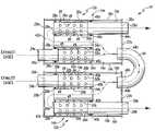
- FIG. 1shows a diagrammatic cross-sectional view of an exemplary embodiment of an exhaust system 10 including mufflers 12 a, 12 b .
- each muffler 12 a - bincludes a housing 14 a , 14 b .
- Each housing 14 a - bincludes an inner layer 16 a , 16 b and an outer layer 18 a , 18 b .
- housings 14 a - bmay each include only a single layer.
- Each muffler 12 a - bincludes an inlet end plate 20 a , 20 b and an outlet plate 22 a , 22 b secured to the housing 14 a - b .
- each end plate 20 a - b , 22 a - bis secured to the housing 14 a - b through a lockseam connection, however, it should be appreciated the end plates 20 a - b , 22 a - b may be secured in other manners, such as welding or brazing.
- the exhaust system 10includes inlet pipes 24 a , 24 b , which each extend through an opening 26 a , 26 b in each inlet end plate 20 a - b of mufflers 12 a - b and into the housing 14 a - b.
- outlet pipes 28 a , 28 beach extend through an opening 30 a , 30 b in each outlet plate 22 a - b of mufflers 12 a - b and into the housing 14 a - b .
- Each muffler 12 a - bincludes an inlet tube 32 a , 32 b , an intermediate tube 34 a , 34 b , and an outlet tube 36 a , 36 b disposed within the housing 14 a , 14 b .
- each tube 32 a - b , 34 a - b , 36 a - bis arranged such that the longitudinal axes of each are substantially parallel to one another.
- Each muffler 12 a - bincludes a first baffle 38 a , 38 b and a second baffle 40 a , 40 b disposed within the housing 14 a - b .
- the baffles 38 a - b , 40 a - bare configured to each provide a “wall” in the housings 14 a - b .
- the baffles 38 a - b , 40 a - bmay be secured to the inner layer 16 a - b of the housing 14 a - b in various manners. In the exemplary embodiment of FIG.
- the baffles 38 a - b , 40 a - bare spot welded to the inner layers 16 a - b .
- the tubes 32 a - b , 34 a - b , 36 a - bare each disposed through a first baffle 38 a - b and a second baffle 40 a - b so that each end of the tubes is either exposed to an area 42 a , 42 b located between the first baffle 38 a - b and the inlet end cap 20 a - b or to an area 44 a , 44 b located between the second baffle 40 a - b and the outlet end cap 22 a - b .
- Each inlet tube 32 a - bis connected to an inlet pipe 24 a - b and each outlet tube 32 a - b is connected to an outlet pipe 28 a - b.
- a crossbleed pipe 46which is substantially U-shaped, extends through openings 48 a , 48 b in outlet end plates 22 a - b .
- the crossbleed pipe 46allows the interiors of the housings 14 a - b to fluidly communicate with one another as the exhaust gases flow through the exhaust system 10 as represented by the dotted line.
- the end plates 20 a - b , 22 a - bare substantially flat allowing the inlet pipes 24 a - b, outlet pipes 28 a - b , and crossbleed pipe 46 to be easily disposed therethrough and secured in place.
- a weldmay be formed at the intersection of the end plates 20 a - b , 22 a - b and the pipes 24 a - b , 26 a - b , 46 extending therethrough.
- exhaust gasesmay flow through the inlet pipes 24 a - b into the inlet tubes 32 a - b as indicated by the dotted line shown in FIG. 1 , which represents the flow of exhaust gases through mufflers 12 a - b .
- the exhaust gasesexit inlet tubes 32 a - b and enter area 44 a - b .
- the interaction of the second baffles 40 a - b and the pressures associated with the exhaust gas flowdirect the exhaust gases into the intermediate tubes 34 a - b .
- the exhaust gasesmay also flow through crossbleed pipe 46 as well.
- the exhaust gasesflow through intermediate tubes 34 a - b into area 42 a - b , where the first baffles 38 a - b and exhaust gas flow pressure direct the exhaust gases into outlet tubes 36 a - b and through the outlet pipes 28 a - b , where the exhaust gases may be released into the atmosphere or conducted downstream to other portions of the exhaust system 10 .
- the dotted line shown in FIGS. 1 and 2represent the general path of the exhaust gases flowing through the exhaust system 10 , as well as a general representation of how components of the exhaust system 10 may interact with one another in directing exhaust gas flow.
- the inlet tubes 32 a - b and outlet tubes 36 a - bare shown to include a number of louvers 49 formed therein.
- the louvers 49allow the exhaust gases flowing though the inlet tubes 32 a - b and outlet tubes 36 a - b to fluidly communicate directly with area 50 a , 50 b located between the first baffle 38 a - b and second baffle 40 a - b .
- the louvers 49may be formed in the intermediate tubes 34 a - b and that the inlet tubes 32 a - b and outlet tubes 36 a - b may be formed without the louvers 49 disposed therein.
- the areas 50 a , 50 bmay be filled with an acoustically absorbent material such as mineral wool or steel wool.
- the outlet tubes 36 a - bmay be wrapped in a stainless steel wrap, to prevent the acoustically absorbent material from entering the outlet tubes 36 a - b .
- baffles 38 a - b , 40 a - bmay each be perforated allowing areas 42 a - b , 44 a - b , and 50 a - b to fluidly communicate with one another.
- FIG. 2shows a diagrammatic cross-sectional view of the exhaust system 10 having an alternative configuration than that shown in FIG. 1 .
- the crossbleed pipe 46extends through an opening 52 a , 52 b in each of the inlet end plates 20 a , 20 b (as opposed to the outlet end plates 22 a - b , as shown in FIG. 1 ).
- end plates 20 a - b , 22 a - bare substantially flat.
- the configuration shown in FIG. 2presents a “mirror image” to that of FIG.
- FIG. 2The exhaust flow path is shown in FIG. 2 through a dotted line, similar to FIG. 1 , with crossbleed pipe 46 fluidly communicating directly with area 42 a - b , as opposed to 44 a - b in FIG. 1 .
- the inlet pipes 24 a - b and outlet pipes 28 a - b of each muffler 12 a - bmay extend through the same end plate, such as the end plate 20 a - b or 22 a - b such that the exhaust gases enter and exit the same end of the mufflers 12 a - b .
- the crossbleed pipe 46may extend through either the inlet end plates 20 a - b or the outlet end plates 22 a - b of each muffler 12 a - b.
- FIG. 3shows an outlet end view of a muffler 12 similar to that shown in FIG. 1 without an inlet pipe 24 or a crossbreed pipe 26 present.
- the openings 30 , 48are shown in the outlet end plate 22 .
- This viewfurther illustrates the lockseam connection 54 , which connects the outlet end plate 22 to the housing 14 .
- the inlet end plate 20(not shown) is connected in a similar manner to housing 14 .
Landscapes
- Engineering & Computer Science (AREA)
- Chemical & Material Sciences (AREA)
- Combustion & Propulsion (AREA)
- Mechanical Engineering (AREA)
- General Engineering & Computer Science (AREA)
- Exhaust Silencers (AREA)
Abstract
Description
Claims (29)
Priority Applications (1)
| Application Number | Priority Date | Filing Date | Title |
|---|---|---|---|
| US11/450,043US7650965B2 (en) | 2006-06-09 | 2006-06-09 | Exhaust system |
Applications Claiming Priority (1)
| Application Number | Priority Date | Filing Date | Title |
|---|---|---|---|
| US11/450,043US7650965B2 (en) | 2006-06-09 | 2006-06-09 | Exhaust system |
Publications (2)
| Publication Number | Publication Date |
|---|---|
| US20070284186A1 US20070284186A1 (en) | 2007-12-13 |
| US7650965B2true US7650965B2 (en) | 2010-01-26 |
Family
ID=38820756
Family Applications (1)
| Application Number | Title | Priority Date | Filing Date |
|---|---|---|---|
| US11/450,043Expired - Fee RelatedUS7650965B2 (en) | 2006-06-09 | 2006-06-09 | Exhaust system |
Country Status (1)
| Country | Link |
|---|---|
| US (1) | US7650965B2 (en) |
Cited By (26)
| Publication number | Priority date | Publication date | Assignee | Title |
|---|---|---|---|---|
| US8256571B1 (en) | 2010-10-29 | 2012-09-04 | Butler Boyd L | Frequency-modifying muffler |
| US8746401B2 (en) | 2010-10-29 | 2014-06-10 | Boyd L. Butler | Frequency-modifying muffler |
| US8827035B2 (en) | 2012-12-03 | 2014-09-09 | Ford Global Technologies, Llc | Conformal transverse muffler |
| US20150136520A1 (en)* | 2013-11-15 | 2015-05-21 | Hyundai Motor Company | Structure of dual exhaust system for cda engine |
| US9611770B2 (en)* | 2014-05-28 | 2017-04-04 | Suzuki Motor Corporation | Exhaust pipe structure for vehicle |
| US10622214B2 (en) | 2017-05-25 | 2020-04-14 | Applied Materials, Inc. | Tungsten defluorination by high pressure treatment |
| US10636677B2 (en) | 2017-08-18 | 2020-04-28 | Applied Materials, Inc. | High pressure and high temperature anneal chamber |
| US10636669B2 (en) | 2018-01-24 | 2020-04-28 | Applied Materials, Inc. | Seam healing using high pressure anneal |
| US10675581B2 (en)* | 2018-08-06 | 2020-06-09 | Applied Materials, Inc. | Gas abatement apparatus |
| US10685830B2 (en) | 2017-11-17 | 2020-06-16 | Applied Materials, Inc. | Condenser system for high pressure processing system |
| US10704141B2 (en) | 2018-06-01 | 2020-07-07 | Applied Materials, Inc. | In-situ CVD and ALD coating of chamber to control metal contamination |
| US10714331B2 (en) | 2018-04-04 | 2020-07-14 | Applied Materials, Inc. | Method to fabricate thermally stable low K-FinFET spacer |
| US10720341B2 (en) | 2017-11-11 | 2020-07-21 | Micromaterials, LLC | Gas delivery system for high pressure processing chamber |
| US10748783B2 (en) | 2018-07-25 | 2020-08-18 | Applied Materials, Inc. | Gas delivery module |
| US10787951B2 (en) | 2017-11-20 | 2020-09-29 | Tenneco Automotive Operating Company Inc. | Pipe and metal sheet subassembly for an exhaust treatment device |
| US10847360B2 (en) | 2017-05-25 | 2020-11-24 | Applied Materials, Inc. | High pressure treatment of silicon nitride film |
| US10854483B2 (en) | 2017-11-16 | 2020-12-01 | Applied Materials, Inc. | High pressure steam anneal processing apparatus |
| US10957533B2 (en) | 2018-10-30 | 2021-03-23 | Applied Materials, Inc. | Methods for etching a structure for semiconductor applications |
| US10998200B2 (en) | 2018-03-09 | 2021-05-04 | Applied Materials, Inc. | High pressure annealing process for metal containing materials |
| US11018032B2 (en) | 2017-08-18 | 2021-05-25 | Applied Materials, Inc. | High pressure and high temperature anneal chamber |
| US11177128B2 (en) | 2017-09-12 | 2021-11-16 | Applied Materials, Inc. | Apparatus and methods for manufacturing semiconductor structures using protective barrier layer |
| US11227797B2 (en) | 2018-11-16 | 2022-01-18 | Applied Materials, Inc. | Film deposition using enhanced diffusion process |
| US11581183B2 (en) | 2018-05-08 | 2023-02-14 | Applied Materials, Inc. | Methods of forming amorphous carbon hard mask layers and hard mask layers formed therefrom |
| US11749555B2 (en) | 2018-12-07 | 2023-09-05 | Applied Materials, Inc. | Semiconductor processing system |
| US11901222B2 (en) | 2020-02-17 | 2024-02-13 | Applied Materials, Inc. | Multi-step process for flowable gap-fill film |
| US12198951B2 (en) | 2017-03-10 | 2025-01-14 | Applied Materials, Inc. | High pressure wafer processing systems and related methods |
Families Citing this family (5)
| Publication number | Priority date | Publication date | Assignee | Title |
|---|---|---|---|---|
| DE102004022721A1 (en)* | 2004-05-07 | 2005-11-24 | Dr.Ing.H.C. F. Porsche Ag | Double-flow exhaust system for an internal combustion engine |
| CN101371013B (en)* | 2006-01-17 | 2011-06-01 | 丰田自动车株式会社 | Vehicle muffler structure |
| US7650965B2 (en)* | 2006-06-09 | 2010-01-26 | Emcon Technologies Llc | Exhaust system |
| DE102007062663A1 (en)* | 2007-12-24 | 2009-06-25 | J. Eberspächer GmbH & Co. KG | Sliding seat and pipe arrangement and exhaust treatment device |
| DE102009014435A1 (en)* | 2009-03-26 | 2010-10-14 | J. Eberspächer GmbH & Co. KG | Exhaust gas treatment device |
Citations (76)
| Publication number | Priority date | Publication date | Assignee | Title |
|---|---|---|---|---|
| US2537203A (en)* | 1945-05-05 | 1951-01-09 | Maxim Silencer Co | Manifold silencer |
| US2692025A (en)* | 1951-08-08 | 1954-10-19 | Maxim Silencer Co | Heavy-duty silencer for restricted spaces |
| US2940249A (en)* | 1955-10-25 | 1960-06-14 | Volkswagenwerk Ag | Exhaust head for internal combustion engines |
| US3043098A (en)* | 1961-10-17 | 1962-07-10 | Hanlon & Wilson Co | Exhaust heater-muffler combination |
| US3114430A (en)* | 1961-03-06 | 1963-12-17 | Burgess Manning Co | Pulsation snubber or silencer |
| US3166150A (en)* | 1961-02-17 | 1965-01-19 | William H Phelps | Engine exhaust silencer |
| US3388769A (en)* | 1966-08-04 | 1968-06-18 | Walker Mfg Co | Dual inlet and outlet muffler |
| US3419107A (en)* | 1967-07-03 | 1968-12-31 | Nash Engineering Co | Manifold muffler arrangement |
| US3545414A (en)* | 1969-05-21 | 1970-12-08 | Modern Tube Bending & Mfg | Exhaust header |
| US3709320A (en)* | 1970-10-15 | 1973-01-09 | Meinel Georgadel O Metallwaren | Exhaust means for multiple cylinder internal combustion engine |
| US3711013A (en)* | 1971-04-26 | 1973-01-16 | Rohr Corp | Thrust control and sound apparatus |
| US3739873A (en)* | 1971-09-03 | 1973-06-19 | Tenneco Inc | Dual outlet exhaust system |
| US3763950A (en)* | 1971-12-17 | 1973-10-09 | Rockwell H Brown | Combination frame and exhaust system for motor vehicles |
| US3794139A (en) | 1973-01-02 | 1974-02-26 | Tenneco Inc | Muffler with plural inlets and outlets |
| US3842940A (en)* | 1969-04-17 | 1974-10-22 | Wytwornia Silnikow Wysokoprezn | Silencer for internal combustion engines |
| US3949829A (en)* | 1973-12-22 | 1976-04-13 | Honda Giken Kogyo Kabushiki Kaisha | Exhaust silencer for motorcycle |
| US3972384A (en)* | 1975-04-17 | 1976-08-03 | Ralph Electric Plants, Inc. | Spark arresting muffler |
| JPS54145825A (en)* | 1978-05-04 | 1979-11-14 | Yamaha Motor Co Ltd | Exhaust pipe for car |
| US4310067A (en)* | 1968-11-27 | 1982-01-12 | The United States Of America As Represented By The Secretary Of The Navy | Optimized diesel engine exhaust silencer |
| US4342195A (en)* | 1980-08-15 | 1982-08-03 | Lo Ching P | Motorcycle exhaust system |
| US4359865A (en)* | 1979-08-31 | 1982-11-23 | Yamaha Hatsudoki Kabushiki Kaisha | Exhaust system for multicylinder motorbike engine |
| US4422519A (en)* | 1978-09-29 | 1983-12-27 | Yamaha Hatsudoki Kabushiki Kaisha | Motorcycle engine exhaust system |
| JPS5968520A (en)* | 1982-10-12 | 1984-04-18 | Yamaha Motor Co Ltd | Exhaust device for internal-combustion engine with multi-cylinders |
| US4487288A (en)* | 1981-07-03 | 1984-12-11 | Kawasaki Jukogyo Kabushiki Kaisha | Muffler device of motorcycle |
| JPS62615A (en)* | 1985-06-26 | 1987-01-06 | Honda Motor Co Ltd | Muffler chamber structure of motorcycle |
| US4760894A (en)* | 1987-06-11 | 1988-08-02 | Ap Industries, Inc. | Exhaust muffler with angularly aligned inlets and outlets |
| US4765137A (en)* | 1986-03-07 | 1988-08-23 | Yamaha Hatsudoki Kabushiki Kaisha | Exhaust gas control means for engine |
| US4790409A (en) | 1987-05-14 | 1988-12-13 | Tenneco, Inc. | Muffler with reverse flow passages |
| US4819428A (en)* | 1986-02-27 | 1989-04-11 | Alfa Romeo Auto S.P.A. | Exhaust system for an internal combustion engine |
| US4869063A (en)* | 1986-03-07 | 1989-09-26 | Yamaha Hatsudoki Kabushiki Kaisha | Exhaust gas control means for engine |
| US4923035A (en) | 1987-11-18 | 1990-05-08 | Bbc Brown Boveri Ag | Low-frequency muffler |
| US4953660A (en)* | 1989-02-09 | 1990-09-04 | Tennessee Gas Pipeline Company | Muffler with two part housing and flow tubes |
| US5014817A (en) | 1988-07-29 | 1991-05-14 | Mazda Motor Corporation | Engine exhaust apparatus and method |
| US5033581A (en)* | 1989-10-02 | 1991-07-23 | Feuling Engineering, Inc. | Muffler for an internal combustion engine |
| JPH0450414A (en) | 1990-06-15 | 1992-02-19 | Nissan Shatai Co Ltd | Exhaust device for vehicle |
| JPH04121407A (en)* | 1990-09-11 | 1992-04-22 | Nissan Shatai Co Ltd | Exhaust device of engine |
| JPH05106420A (en)* | 1991-10-17 | 1993-04-27 | Nissan Motor Co Ltd | Intake / exhaust noise reduction device for internal combustion engine |
| US5351481A (en)* | 1992-06-26 | 1994-10-04 | Flowmaster, Inc. | Muffler assembly with balanced chamber and method |
| US5388408A (en)* | 1993-10-01 | 1995-02-14 | Lawrence-Keech Inc. | Exhaust system for internal combustion engines |
| US5594217A (en)* | 1995-08-09 | 1997-01-14 | Lequire; Wayne A. | Exhaust muffler for small marine craft |
| US5712455A (en)* | 1994-06-06 | 1998-01-27 | Wagner; Dane | Dual entry plug muffler |
| US5723829A (en)* | 1995-02-24 | 1998-03-03 | Calsonic Corporation | Muffler assembly of internal combustion engine |
| US5744762A (en)* | 1995-02-24 | 1998-04-28 | Calsonic Corporation | Muffler controller for use in controllable exhaust system of internal combustion engine |
| US5773770A (en) | 1997-06-11 | 1998-06-30 | Jones; Mack L. | Cross flow path exhaust muffler |
| US6141958A (en)* | 1998-12-31 | 2000-11-07 | Voss; Randy E. | Exhaust cooling system for vehicles |
| US6182446B1 (en)* | 1998-03-19 | 2001-02-06 | Daimlerchrysler A.G. | Internal combustion engine with at least two cylinder banks |
| US6247305B1 (en)* | 1999-10-07 | 2001-06-19 | Darryl C. Bassani | Motorcycle exhaust system |
| US20020033304A1 (en)* | 2000-09-21 | 2002-03-21 | Honda Giken Kogyo Kabushiki Kaisha | Muffler for an engine |
| US20020033302A1 (en)* | 2000-09-11 | 2002-03-21 | Calsonic Kansei Corporation & Nissan Motor Co., Ltd. | Controllable muffler system for internal combustion engine |
| US6382347B1 (en)* | 2001-05-08 | 2002-05-07 | Ghl Motorsports, L.L.C. | Exhaust muffler for an internal combustion engine |
| US6435302B1 (en)* | 2000-12-21 | 2002-08-20 | Shun-Lai Chen | Motor vehicle muffler |
| US6470998B1 (en)* | 1999-10-26 | 2002-10-29 | James E. White | Modular muffler with end plate adaptors and spark arresters |
| US6598390B2 (en)* | 2001-12-26 | 2003-07-29 | Liang Fei Industry Co. Ltd. | Easily controlled exhaust pipe |
| US6644437B1 (en)* | 2002-08-02 | 2003-11-11 | General Motors Corporation | Vehicle exhaust with length-equalizing muffler |
| US6651773B1 (en)* | 2002-09-24 | 2003-11-25 | Gregory M. Marocco | Exhaust sound attenuation and control system |
| US6662900B2 (en)* | 2001-12-21 | 2003-12-16 | Daimlerchrysler Corporation | Cross-exit exhaust system |
| US20040050618A1 (en)* | 1998-08-18 | 2004-03-18 | Marocco Gregory M. | Exhaust sound and emission control systems |
| US6796402B1 (en) | 2003-04-17 | 2004-09-28 | Dane Wagner | Muffler having isolated dual flow baffle structure |
| US20040200665A1 (en)* | 2003-04-08 | 2004-10-14 | Adams Gar M | Exhaust system for V-twin engines |
| US6804955B2 (en) | 2001-09-26 | 2004-10-19 | Darryl C. Bassani | Dual motorcycle exhaust system |
| US6912843B2 (en)* | 2003-01-11 | 2005-07-05 | Daimlerchrysler Ag | Exhaust system for a multi-cylinder internal combustion engine |
| US6942061B2 (en) | 2003-12-17 | 2005-09-13 | Jones Exhaust Systems, Inc. | Muffler for internal combustion engine |
| US20050205351A1 (en)* | 2004-03-18 | 2005-09-22 | D Angelo John P | Noise reduction tubes |
| US6964161B2 (en)* | 2002-09-30 | 2005-11-15 | Monty Allen Campbell | Induction exhaust system |
| US20050279571A1 (en)* | 1998-08-18 | 2005-12-22 | Marocco Gregory M | Exhaust sound and emission control systems |
| US7021052B1 (en)* | 2003-08-29 | 2006-04-04 | Maury Hicks | Motorcycle exhaust control system |
| US7090048B2 (en)* | 2003-09-26 | 2006-08-15 | General Motors Corporation | Method and apparatus for exhaust sound attenuation on engines with cylinder deactivation |
| US20070029133A1 (en)* | 2003-07-12 | 2007-02-08 | Marcus Hofmann | Device for modulating noise in a motor vehicle |
| US20070045041A1 (en)* | 2005-02-11 | 2007-03-01 | Jan Krueger | Muffler for an exhaust system |
| US20070125594A1 (en)* | 2005-12-01 | 2007-06-07 | Hill William E | Muffler assembly with sound absorbing member |
| US20070187175A1 (en)* | 2004-03-26 | 2007-08-16 | Alessandro Gilli | Muffler for exhaust systems of vehicles |
| US20070220872A1 (en)* | 2004-05-07 | 2007-09-27 | Dr. Ing. H.C.F Porsche Aktiengesellchaft | Exhaust System for a Drive Unit Formed by a Transmission and an Engine |
| US20070272479A1 (en)* | 2003-10-02 | 2007-11-29 | Bayerische Motoren Werke Aktiengesellschaft | Exhaust System for an Internal Combustion Engine |
| US20070284186A1 (en)* | 2006-06-09 | 2007-12-13 | Arvin Technologies, Inc. | Exhaust system |
| JP4050414B2 (en) | 1999-02-05 | 2008-02-20 | 財団法人鉄道総合技術研究所 | Dummy doll standing assistance device |
| US7380635B2 (en)* | 2004-06-22 | 2008-06-03 | Gregory Leigh Harris | Interference-based exhaust noise attenuation |
Family Cites Families (1)
| Publication number | Priority date | Publication date | Assignee | Title |
|---|---|---|---|---|
| DE3624986A1 (en)* | 1986-07-24 | 1988-02-04 | Focke & Co | MACHINE, PARTICULARLY PACKING MACHINE |
- 2006
- 2006-06-09USUS11/450,043patent/US7650965B2/ennot_activeExpired - Fee Related
Patent Citations (84)
| Publication number | Priority date | Publication date | Assignee | Title |
|---|---|---|---|---|
| US2537203A (en)* | 1945-05-05 | 1951-01-09 | Maxim Silencer Co | Manifold silencer |
| US2692025A (en)* | 1951-08-08 | 1954-10-19 | Maxim Silencer Co | Heavy-duty silencer for restricted spaces |
| US2940249A (en)* | 1955-10-25 | 1960-06-14 | Volkswagenwerk Ag | Exhaust head for internal combustion engines |
| US3166150A (en)* | 1961-02-17 | 1965-01-19 | William H Phelps | Engine exhaust silencer |
| US3114430A (en)* | 1961-03-06 | 1963-12-17 | Burgess Manning Co | Pulsation snubber or silencer |
| US3043098A (en)* | 1961-10-17 | 1962-07-10 | Hanlon & Wilson Co | Exhaust heater-muffler combination |
| US3388769A (en)* | 1966-08-04 | 1968-06-18 | Walker Mfg Co | Dual inlet and outlet muffler |
| US3419107A (en)* | 1967-07-03 | 1968-12-31 | Nash Engineering Co | Manifold muffler arrangement |
| US4310067A (en)* | 1968-11-27 | 1982-01-12 | The United States Of America As Represented By The Secretary Of The Navy | Optimized diesel engine exhaust silencer |
| US3842940A (en)* | 1969-04-17 | 1974-10-22 | Wytwornia Silnikow Wysokoprezn | Silencer for internal combustion engines |
| US3545414A (en)* | 1969-05-21 | 1970-12-08 | Modern Tube Bending & Mfg | Exhaust header |
| US3709320A (en)* | 1970-10-15 | 1973-01-09 | Meinel Georgadel O Metallwaren | Exhaust means for multiple cylinder internal combustion engine |
| US3711013A (en)* | 1971-04-26 | 1973-01-16 | Rohr Corp | Thrust control and sound apparatus |
| US3739873A (en)* | 1971-09-03 | 1973-06-19 | Tenneco Inc | Dual outlet exhaust system |
| US3763950A (en)* | 1971-12-17 | 1973-10-09 | Rockwell H Brown | Combination frame and exhaust system for motor vehicles |
| US3794139A (en) | 1973-01-02 | 1974-02-26 | Tenneco Inc | Muffler with plural inlets and outlets |
| US3949829A (en)* | 1973-12-22 | 1976-04-13 | Honda Giken Kogyo Kabushiki Kaisha | Exhaust silencer for motorcycle |
| US3972384A (en)* | 1975-04-17 | 1976-08-03 | Ralph Electric Plants, Inc. | Spark arresting muffler |
| JPS54145825A (en)* | 1978-05-04 | 1979-11-14 | Yamaha Motor Co Ltd | Exhaust pipe for car |
| US4422519A (en)* | 1978-09-29 | 1983-12-27 | Yamaha Hatsudoki Kabushiki Kaisha | Motorcycle engine exhaust system |
| US4359865A (en)* | 1979-08-31 | 1982-11-23 | Yamaha Hatsudoki Kabushiki Kaisha | Exhaust system for multicylinder motorbike engine |
| US4342195A (en)* | 1980-08-15 | 1982-08-03 | Lo Ching P | Motorcycle exhaust system |
| US4487288A (en)* | 1981-07-03 | 1984-12-11 | Kawasaki Jukogyo Kabushiki Kaisha | Muffler device of motorcycle |
| JPS5968520A (en)* | 1982-10-12 | 1984-04-18 | Yamaha Motor Co Ltd | Exhaust device for internal-combustion engine with multi-cylinders |
| JPS62615A (en)* | 1985-06-26 | 1987-01-06 | Honda Motor Co Ltd | Muffler chamber structure of motorcycle |
| US4819428A (en)* | 1986-02-27 | 1989-04-11 | Alfa Romeo Auto S.P.A. | Exhaust system for an internal combustion engine |
| US4869063A (en)* | 1986-03-07 | 1989-09-26 | Yamaha Hatsudoki Kabushiki Kaisha | Exhaust gas control means for engine |
| US4765137A (en)* | 1986-03-07 | 1988-08-23 | Yamaha Hatsudoki Kabushiki Kaisha | Exhaust gas control means for engine |
| US4790409A (en) | 1987-05-14 | 1988-12-13 | Tenneco, Inc. | Muffler with reverse flow passages |
| US4760894A (en)* | 1987-06-11 | 1988-08-02 | Ap Industries, Inc. | Exhaust muffler with angularly aligned inlets and outlets |
| US4923035A (en) | 1987-11-18 | 1990-05-08 | Bbc Brown Boveri Ag | Low-frequency muffler |
| US5014817A (en) | 1988-07-29 | 1991-05-14 | Mazda Motor Corporation | Engine exhaust apparatus and method |
| US4953660A (en)* | 1989-02-09 | 1990-09-04 | Tennessee Gas Pipeline Company | Muffler with two part housing and flow tubes |
| US5033581A (en)* | 1989-10-02 | 1991-07-23 | Feuling Engineering, Inc. | Muffler for an internal combustion engine |
| JPH0450414A (en) | 1990-06-15 | 1992-02-19 | Nissan Shatai Co Ltd | Exhaust device for vehicle |
| JPH04121407A (en)* | 1990-09-11 | 1992-04-22 | Nissan Shatai Co Ltd | Exhaust device of engine |
| JPH05106420A (en)* | 1991-10-17 | 1993-04-27 | Nissan Motor Co Ltd | Intake / exhaust noise reduction device for internal combustion engine |
| US5351481A (en)* | 1992-06-26 | 1994-10-04 | Flowmaster, Inc. | Muffler assembly with balanced chamber and method |
| US5388408A (en)* | 1993-10-01 | 1995-02-14 | Lawrence-Keech Inc. | Exhaust system for internal combustion engines |
| US5712455A (en)* | 1994-06-06 | 1998-01-27 | Wagner; Dane | Dual entry plug muffler |
| US5744762A (en)* | 1995-02-24 | 1998-04-28 | Calsonic Corporation | Muffler controller for use in controllable exhaust system of internal combustion engine |
| US5723829A (en)* | 1995-02-24 | 1998-03-03 | Calsonic Corporation | Muffler assembly of internal combustion engine |
| US5594217A (en)* | 1995-08-09 | 1997-01-14 | Lequire; Wayne A. | Exhaust muffler for small marine craft |
| US5773770A (en) | 1997-06-11 | 1998-06-30 | Jones; Mack L. | Cross flow path exhaust muffler |
| US6182446B1 (en)* | 1998-03-19 | 2001-02-06 | Daimlerchrysler A.G. | Internal combustion engine with at least two cylinder banks |
| US7281606B2 (en)* | 1998-08-18 | 2007-10-16 | Marocco Gregory M | Exhaust sound and emission control systems |
| US20080035418A1 (en)* | 1998-08-18 | 2008-02-14 | Marocco Gregory M | Exhaust sound and emission control systems |
| US20050279571A1 (en)* | 1998-08-18 | 2005-12-22 | Marocco Gregory M | Exhaust sound and emission control systems |
| US20040050618A1 (en)* | 1998-08-18 | 2004-03-18 | Marocco Gregory M. | Exhaust sound and emission control systems |
| US6935461B2 (en) | 1998-08-18 | 2005-08-30 | Gregory M. Marocco | Exhaust sound and emission control systems |
| US6141958A (en)* | 1998-12-31 | 2000-11-07 | Voss; Randy E. | Exhaust cooling system for vehicles |
| JP4050414B2 (en) | 1999-02-05 | 2008-02-20 | 財団法人鉄道総合技術研究所 | Dummy doll standing assistance device |
| US6463641B2 (en)* | 1999-10-07 | 2002-10-15 | Darryl C. Bassani | Motorcycle exhaust system |
| US6247305B1 (en)* | 1999-10-07 | 2001-06-19 | Darryl C. Bassani | Motorcycle exhaust system |
| US6470998B1 (en)* | 1999-10-26 | 2002-10-29 | James E. White | Modular muffler with end plate adaptors and spark arresters |
| US20020033302A1 (en)* | 2000-09-11 | 2002-03-21 | Calsonic Kansei Corporation & Nissan Motor Co., Ltd. | Controllable muffler system for internal combustion engine |
| US6755279B2 (en)* | 2000-09-11 | 2004-06-29 | Calsonic Kansei Corporation | Controllable muffler system for internal combustion engine |
| US20020033304A1 (en)* | 2000-09-21 | 2002-03-21 | Honda Giken Kogyo Kabushiki Kaisha | Muffler for an engine |
| US6435302B1 (en)* | 2000-12-21 | 2002-08-20 | Shun-Lai Chen | Motor vehicle muffler |
| US6382347B1 (en)* | 2001-05-08 | 2002-05-07 | Ghl Motorsports, L.L.C. | Exhaust muffler for an internal combustion engine |
| US6804955B2 (en) | 2001-09-26 | 2004-10-19 | Darryl C. Bassani | Dual motorcycle exhaust system |
| US6662900B2 (en)* | 2001-12-21 | 2003-12-16 | Daimlerchrysler Corporation | Cross-exit exhaust system |
| US6598390B2 (en)* | 2001-12-26 | 2003-07-29 | Liang Fei Industry Co. Ltd. | Easily controlled exhaust pipe |
| US6644437B1 (en)* | 2002-08-02 | 2003-11-11 | General Motors Corporation | Vehicle exhaust with length-equalizing muffler |
| US6651773B1 (en)* | 2002-09-24 | 2003-11-25 | Gregory M. Marocco | Exhaust sound attenuation and control system |
| WO2004029561A2 (en) | 2002-09-24 | 2004-04-08 | Marocco Gregory M | Exhaust sound and emission control systems |
| CA2499942A1 (en) | 2002-09-24 | 2004-04-08 | Gregory M. Marocco | Exhaust sound and emission control systems |
| US6964161B2 (en)* | 2002-09-30 | 2005-11-15 | Monty Allen Campbell | Induction exhaust system |
| US6912843B2 (en)* | 2003-01-11 | 2005-07-05 | Daimlerchrysler Ag | Exhaust system for a multi-cylinder internal combustion engine |
| US20040200665A1 (en)* | 2003-04-08 | 2004-10-14 | Adams Gar M | Exhaust system for V-twin engines |
| US6796402B1 (en) | 2003-04-17 | 2004-09-28 | Dane Wagner | Muffler having isolated dual flow baffle structure |
| US20070029133A1 (en)* | 2003-07-12 | 2007-02-08 | Marcus Hofmann | Device for modulating noise in a motor vehicle |
| US7377359B2 (en)* | 2003-07-12 | 2008-05-27 | Daimler Ag | Device for modulating noise in a motor vehicle |
| US7021052B1 (en)* | 2003-08-29 | 2006-04-04 | Maury Hicks | Motorcycle exhaust control system |
| US7090048B2 (en)* | 2003-09-26 | 2006-08-15 | General Motors Corporation | Method and apparatus for exhaust sound attenuation on engines with cylinder deactivation |
| US20070272479A1 (en)* | 2003-10-02 | 2007-11-29 | Bayerische Motoren Werke Aktiengesellschaft | Exhaust System for an Internal Combustion Engine |
| US6942061B2 (en) | 2003-12-17 | 2005-09-13 | Jones Exhaust Systems, Inc. | Muffler for internal combustion engine |
| US20050205351A1 (en)* | 2004-03-18 | 2005-09-22 | D Angelo John P | Noise reduction tubes |
| US20070187175A1 (en)* | 2004-03-26 | 2007-08-16 | Alessandro Gilli | Muffler for exhaust systems of vehicles |
| US20070220872A1 (en)* | 2004-05-07 | 2007-09-27 | Dr. Ing. H.C.F Porsche Aktiengesellchaft | Exhaust System for a Drive Unit Formed by a Transmission and an Engine |
| US7380635B2 (en)* | 2004-06-22 | 2008-06-03 | Gregory Leigh Harris | Interference-based exhaust noise attenuation |
| US20070045041A1 (en)* | 2005-02-11 | 2007-03-01 | Jan Krueger | Muffler for an exhaust system |
| US20070125594A1 (en)* | 2005-12-01 | 2007-06-07 | Hill William E | Muffler assembly with sound absorbing member |
| US20070284186A1 (en)* | 2006-06-09 | 2007-12-13 | Arvin Technologies, Inc. | Exhaust system |
Cited By (38)
| Publication number | Priority date | Publication date | Assignee | Title |
|---|---|---|---|---|
| US8746401B2 (en) | 2010-10-29 | 2014-06-10 | Boyd L. Butler | Frequency-modifying muffler |
| US8256571B1 (en) | 2010-10-29 | 2012-09-04 | Butler Boyd L | Frequency-modifying muffler |
| US8827035B2 (en) | 2012-12-03 | 2014-09-09 | Ford Global Technologies, Llc | Conformal transverse muffler |
| US9341102B2 (en) | 2012-12-03 | 2016-05-17 | Ford Global Technologies, Llc | Conformal transverse muffler |
| US20150136520A1 (en)* | 2013-11-15 | 2015-05-21 | Hyundai Motor Company | Structure of dual exhaust system for cda engine |
| US9212593B2 (en)* | 2013-11-15 | 2015-12-15 | Hyundai Motor Company | Structure of dual exhaust system for CDA engine |
| US9611770B2 (en)* | 2014-05-28 | 2017-04-04 | Suzuki Motor Corporation | Exhaust pipe structure for vehicle |
| US12198951B2 (en) | 2017-03-10 | 2025-01-14 | Applied Materials, Inc. | High pressure wafer processing systems and related methods |
| US11705337B2 (en) | 2017-05-25 | 2023-07-18 | Applied Materials, Inc. | Tungsten defluorination by high pressure treatment |
| US10622214B2 (en) | 2017-05-25 | 2020-04-14 | Applied Materials, Inc. | Tungsten defluorination by high pressure treatment |
| US10847360B2 (en) | 2017-05-25 | 2020-11-24 | Applied Materials, Inc. | High pressure treatment of silicon nitride film |
| US11469113B2 (en) | 2017-08-18 | 2022-10-11 | Applied Materials, Inc. | High pressure and high temperature anneal chamber |
| US11694912B2 (en) | 2017-08-18 | 2023-07-04 | Applied Materials, Inc. | High pressure and high temperature anneal chamber |
| US11018032B2 (en) | 2017-08-18 | 2021-05-25 | Applied Materials, Inc. | High pressure and high temperature anneal chamber |
| US11462417B2 (en) | 2017-08-18 | 2022-10-04 | Applied Materials, Inc. | High pressure and high temperature anneal chamber |
| US10636677B2 (en) | 2017-08-18 | 2020-04-28 | Applied Materials, Inc. | High pressure and high temperature anneal chamber |
| US11177128B2 (en) | 2017-09-12 | 2021-11-16 | Applied Materials, Inc. | Apparatus and methods for manufacturing semiconductor structures using protective barrier layer |
| US11527421B2 (en) | 2017-11-11 | 2022-12-13 | Micromaterials, LLC | Gas delivery system for high pressure processing chamber |
| US10720341B2 (en) | 2017-11-11 | 2020-07-21 | Micromaterials, LLC | Gas delivery system for high pressure processing chamber |
| US11756803B2 (en) | 2017-11-11 | 2023-09-12 | Applied Materials, Inc. | Gas delivery system for high pressure processing chamber |
| US10854483B2 (en) | 2017-11-16 | 2020-12-01 | Applied Materials, Inc. | High pressure steam anneal processing apparatus |
| US11610773B2 (en) | 2017-11-17 | 2023-03-21 | Applied Materials, Inc. | Condenser system for high pressure processing system |
| US10685830B2 (en) | 2017-11-17 | 2020-06-16 | Applied Materials, Inc. | Condenser system for high pressure processing system |
| US10787951B2 (en) | 2017-11-20 | 2020-09-29 | Tenneco Automotive Operating Company Inc. | Pipe and metal sheet subassembly for an exhaust treatment device |
| US10636669B2 (en) | 2018-01-24 | 2020-04-28 | Applied Materials, Inc. | Seam healing using high pressure anneal |
| US11881411B2 (en) | 2018-03-09 | 2024-01-23 | Applied Materials, Inc. | High pressure annealing process for metal containing materials |
| US10998200B2 (en) | 2018-03-09 | 2021-05-04 | Applied Materials, Inc. | High pressure annealing process for metal containing materials |
| US10714331B2 (en) | 2018-04-04 | 2020-07-14 | Applied Materials, Inc. | Method to fabricate thermally stable low K-FinFET spacer |
| US11581183B2 (en) | 2018-05-08 | 2023-02-14 | Applied Materials, Inc. | Methods of forming amorphous carbon hard mask layers and hard mask layers formed therefrom |
| US10704141B2 (en) | 2018-06-01 | 2020-07-07 | Applied Materials, Inc. | In-situ CVD and ALD coating of chamber to control metal contamination |
| US11361978B2 (en) | 2018-07-25 | 2022-06-14 | Applied Materials, Inc. | Gas delivery module |
| US10748783B2 (en) | 2018-07-25 | 2020-08-18 | Applied Materials, Inc. | Gas delivery module |
| US10675581B2 (en)* | 2018-08-06 | 2020-06-09 | Applied Materials, Inc. | Gas abatement apparatus |
| US11110383B2 (en) | 2018-08-06 | 2021-09-07 | Applied Materials, Inc. | Gas abatement apparatus |
| US10957533B2 (en) | 2018-10-30 | 2021-03-23 | Applied Materials, Inc. | Methods for etching a structure for semiconductor applications |
| US11227797B2 (en) | 2018-11-16 | 2022-01-18 | Applied Materials, Inc. | Film deposition using enhanced diffusion process |
| US11749555B2 (en) | 2018-12-07 | 2023-09-05 | Applied Materials, Inc. | Semiconductor processing system |
| US11901222B2 (en) | 2020-02-17 | 2024-02-13 | Applied Materials, Inc. | Multi-step process for flowable gap-fill film |
Also Published As
| Publication number | Publication date |
|---|---|
| US20070284186A1 (en) | 2007-12-13 |
Similar Documents
| Publication | Publication Date | Title |
|---|---|---|
| US7650965B2 (en) | Exhaust system | |
| US8869932B2 (en) | Crossover muffler | |
| JP3314241B2 (en) | Exhaust gas purification device for motorcycle engine | |
| US8083025B2 (en) | Silencer provided on exhaust pipe of vehicle engine | |
| EP2187013B1 (en) | Construction for an exhaust after treatment device | |
| US9556781B2 (en) | Exhaust gas aftertreatment module | |
| JP4024127B2 (en) | Exhaust device for internal combustion engine | |
| US8191581B2 (en) | Wire tube structure for exhaust component | |
| EP2781707B1 (en) | Engine muffler | |
| JP2006329030A (en) | Exhaust apparatus, engine system and vehicle equipped with it | |
| JP4459218B2 (en) | Vehicle exhaust silencer | |
| JP6000168B2 (en) | Muffler with catalytic converter | |
| EP1607594A1 (en) | Exhaust silencer for internal combustion engine | |
| JP4542915B2 (en) | Exhaust heat recovery device | |
| US20200256227A1 (en) | Exhaust system as well as motor vehicle with an exhaust system | |
| CN111788373B (en) | Device for exhaust gas aftertreatment | |
| US20240229693A1 (en) | Exhaust muffler for internal combustion engines | |
| KR100925869B1 (en) | silencer | |
| JP5050560B2 (en) | Exhaust manifold | |
| JP2004052594A (en) | Exhaust manifold structure for engine | |
| JP3623040B2 (en) | Silencer | |
| US20080011541A1 (en) | Internal combustion engine | |
| JPH10205324A (en) | Exhaust device with catalyst | |
| GB2101206A (en) | I.C. engine exhaust gas silencer | |
| JP2004252217A (en) | Silencer |
Legal Events
| Date | Code | Title | Description |
|---|---|---|---|
| AS | Assignment | Owner name:ARVIN TECHNOLOGIES, INC., MICHIGAN Free format text:ASSIGNMENT OF ASSIGNORS INTEREST;ASSIGNORS:THAYER, AARON M.;ARBUCKLE, IVAN S.;JACKSON, BENJAMIN E.;REEL/FRAME:017989/0884;SIGNING DATES FROM 20060608 TO 20060609 | |
| AS | Assignment | Owner name:ET US HOLDINGS LLC, DELAWARE Free format text:ASSIGNMENT OF ASSIGNORS INTEREST;ASSIGNOR:ARVIN TECHNOLOGIES, INC.;REEL/FRAME:019378/0744 Effective date:20070516 Owner name:ET US HOLDINGS LLC,DELAWARE Free format text:ASSIGNMENT OF ASSIGNORS INTEREST;ASSIGNOR:ARVIN TECHNOLOGIES, INC.;REEL/FRAME:019378/0744 Effective date:20070516 | |
| AS | Assignment | Owner name:THE CIT GROUP/BUSINESS CREDIT, INC., ILLINOIS Free format text:SECURITY AGREEMENT;ASSIGNOR:ET US HOLDINGS LLC;REEL/FRAME:019353/0736 Effective date:20070525 Owner name:THE CIT GROUP/BUSINESS CREDIT, INC.,ILLINOIS Free format text:SECURITY AGREEMENT;ASSIGNOR:ET US HOLDINGS LLC;REEL/FRAME:019353/0736 Effective date:20070525 | |
| STCF | Information on status: patent grant | Free format text:PATENTED CASE | |
| AS | Assignment | Owner name:EMCON TECHNOLOGIES LLC (FORMERLY KNOWN AS ET US HO Free format text:RELEASE BY SECURED PARTY;ASSIGNOR:CIT GROUP/BUSINESS CREDIT, INC.;REEL/FRAME:023957/0741 Effective date:20100208 | |
| CC | Certificate of correction | ||
| FPAY | Fee payment | Year of fee payment:4 | |
| FPAY | Fee payment | Year of fee payment:8 | |
| FEPP | Fee payment procedure | Free format text:MAINTENANCE FEE REMINDER MAILED (ORIGINAL EVENT CODE: REM.); ENTITY STATUS OF PATENT OWNER: LARGE ENTITY | |
| LAPS | Lapse for failure to pay maintenance fees | Free format text:PATENT EXPIRED FOR FAILURE TO PAY MAINTENANCE FEES (ORIGINAL EVENT CODE: EXP.); ENTITY STATUS OF PATENT OWNER: LARGE ENTITY | |
| STCH | Information on status: patent discontinuation | Free format text:PATENT EXPIRED DUE TO NONPAYMENT OF MAINTENANCE FEES UNDER 37 CFR 1.362 | |
| FP | Lapsed due to failure to pay maintenance fee | Effective date:20220126 |