US7650624B2 - Method and apparatus for modulating a video signal with data - Google Patents
Method and apparatus for modulating a video signal with dataDownload PDFInfo
- Publication number
- US7650624B2 US7650624B2US10/676,940US67694003AUS7650624B2US 7650624 B2US7650624 B2US 7650624B2US 67694003 AUS67694003 AUS 67694003AUS 7650624 B2US7650624 B2US 7650624B2
- Authority
- US
- United States
- Prior art keywords
- field
- segment
- segments
- video signal
- data
- Prior art date
- Legal status (The legal status is an assumption and is not a legal conclusion. Google has not performed a legal analysis and makes no representation as to the accuracy of the status listed.)
- Active - Reinstated, expires
Links
Images


Classifications
- H—ELECTRICITY
- H04—ELECTRIC COMMUNICATION TECHNIQUE
- H04N—PICTORIAL COMMUNICATION, e.g. TELEVISION
- H04N7/00—Television systems
- H04N7/14—Systems for two-way working
- H—ELECTRICITY
- H04—ELECTRIC COMMUNICATION TECHNIQUE
- H04N—PICTORIAL COMMUNICATION, e.g. TELEVISION
- H04N21/00—Selective content distribution, e.g. interactive television or video on demand [VOD]
- H04N21/40—Client devices specifically adapted for the reception of or interaction with content, e.g. set-top-box [STB]; Operations thereof
- H04N21/41—Structure of client; Structure of client peripherals
- H04N21/414—Specialised client platforms, e.g. receiver in car or embedded in a mobile appliance
- H04N21/41407—Specialised client platforms, e.g. receiver in car or embedded in a mobile appliance embedded in a portable device, e.g. video client on a mobile phone, PDA, laptop
- G—PHYSICS
- G06—COMPUTING OR CALCULATING; COUNTING
- G06Q—INFORMATION AND COMMUNICATION TECHNOLOGY [ICT] SPECIALLY ADAPTED FOR ADMINISTRATIVE, COMMERCIAL, FINANCIAL, MANAGERIAL OR SUPERVISORY PURPOSES; SYSTEMS OR METHODS SPECIALLY ADAPTED FOR ADMINISTRATIVE, COMMERCIAL, FINANCIAL, MANAGERIAL OR SUPERVISORY PURPOSES, NOT OTHERWISE PROVIDED FOR
- G06Q30/00—Commerce
- G06Q30/02—Marketing; Price estimation or determination; Fundraising
- G06Q30/0207—Discounts or incentives, e.g. coupons or rebates
- H—ELECTRICITY
- H04—ELECTRIC COMMUNICATION TECHNIQUE
- H04N—PICTORIAL COMMUNICATION, e.g. TELEVISION
- H04N21/00—Selective content distribution, e.g. interactive television or video on demand [VOD]
- H04N21/20—Servers specifically adapted for the distribution of content, e.g. VOD servers; Operations thereof
- H04N21/23—Processing of content or additional data; Elementary server operations; Server middleware
- H04N21/235—Processing of additional data, e.g. scrambling of additional data or processing content descriptors
- H—ELECTRICITY
- H04—ELECTRIC COMMUNICATION TECHNIQUE
- H04N—PICTORIAL COMMUNICATION, e.g. TELEVISION
- H04N21/00—Selective content distribution, e.g. interactive television or video on demand [VOD]
- H04N21/40—Client devices specifically adapted for the reception of or interaction with content, e.g. set-top-box [STB]; Operations thereof
- H04N21/43—Processing of content or additional data, e.g. demultiplexing additional data from a digital video stream; Elementary client operations, e.g. monitoring of home network or synchronising decoder's clock; Client middleware
- H04N21/435—Processing of additional data, e.g. decrypting of additional data, reconstructing software from modules extracted from the transport stream
- H—ELECTRICITY
- H04—ELECTRIC COMMUNICATION TECHNIQUE
- H04N—PICTORIAL COMMUNICATION, e.g. TELEVISION
- H04N21/00—Selective content distribution, e.g. interactive television or video on demand [VOD]
- H04N21/40—Client devices specifically adapted for the reception of or interaction with content, e.g. set-top-box [STB]; Operations thereof
- H04N21/43—Processing of content or additional data, e.g. demultiplexing additional data from a digital video stream; Elementary client operations, e.g. monitoring of home network or synchronising decoder's clock; Client middleware
- H04N21/436—Interfacing a local distribution network, e.g. communicating with another STB or one or more peripheral devices inside the home
- H04N21/4363—Adapting the video stream to a specific local network, e.g. a Bluetooth® network
- H04N21/43637—Adapting the video stream to a specific local network, e.g. a Bluetooth® network involving a wireless protocol, e.g. Bluetooth, RF or wireless LAN [IEEE 802.11]
- H—ELECTRICITY
- H04—ELECTRIC COMMUNICATION TECHNIQUE
- H04N—PICTORIAL COMMUNICATION, e.g. TELEVISION
- H04N21/00—Selective content distribution, e.g. interactive television or video on demand [VOD]
- H04N21/40—Client devices specifically adapted for the reception of or interaction with content, e.g. set-top-box [STB]; Operations thereof
- H04N21/47—End-user applications
- H04N21/478—Supplemental services, e.g. displaying phone caller identification, shopping application
- H04N21/4784—Supplemental services, e.g. displaying phone caller identification, shopping application receiving rewards
- H—ELECTRICITY
- H04—ELECTRIC COMMUNICATION TECHNIQUE
- H04N—PICTORIAL COMMUNICATION, e.g. TELEVISION
- H04N21/00—Selective content distribution, e.g. interactive television or video on demand [VOD]
- H04N21/80—Generation or processing of content or additional data by content creator independently of the distribution process; Content per se
- H04N21/81—Monomedia components thereof
- H04N21/8166—Monomedia components thereof involving executable data, e.g. software
- H—ELECTRICITY
- H04—ELECTRIC COMMUNICATION TECHNIQUE
- H04N—PICTORIAL COMMUNICATION, e.g. TELEVISION
- H04N7/00—Television systems
- H04N7/025—Systems for the transmission of digital non-picture data, e.g. of text during the active part of a television frame
- H—ELECTRICITY
- H04—ELECTRIC COMMUNICATION TECHNIQUE
- H04N—PICTORIAL COMMUNICATION, e.g. TELEVISION
- H04N7/00—Television systems
- H04N7/08—Systems for the simultaneous or sequential transmission of more than one television signal, e.g. additional information signals, the signals occupying wholly or partially the same frequency band, e.g. by time division
- H04N7/081—Systems for the simultaneous or sequential transmission of more than one television signal, e.g. additional information signals, the signals occupying wholly or partially the same frequency band, e.g. by time division the additional information signals being transmitted by means of a subcarrier
- H—ELECTRICITY
- H04—ELECTRIC COMMUNICATION TECHNIQUE
- H04N—PICTORIAL COMMUNICATION, e.g. TELEVISION
- H04N7/00—Television systems
- H04N7/16—Analogue secrecy systems; Analogue subscription systems
- H04N7/173—Analogue secrecy systems; Analogue subscription systems with two-way working, e.g. subscriber sending a programme selection signal
- H04N7/17309—Transmission or handling of upstream communications
- H04N7/17318—Direct or substantially direct transmission and handling of requests
- H—ELECTRICITY
- H04—ELECTRIC COMMUNICATION TECHNIQUE
- H04N—PICTORIAL COMMUNICATION, e.g. TELEVISION
- H04N21/00—Selective content distribution, e.g. interactive television or video on demand [VOD]
- H04N21/40—Client devices specifically adapted for the reception of or interaction with content, e.g. set-top-box [STB]; Operations thereof
- H04N21/47—End-user applications
- H04N21/478—Supplemental services, e.g. displaying phone caller identification, shopping application
Definitions
- the present inventionrelates to interactive hand-held devices, and more particularly to a method and apparatus for modulating video signals with auxiliary data for reception on and use by receivers such as hand-held devices, and providing promotional opportunities and other benefits to users of these receivers from the reception of the signals.
- auxiliary datafor purposes including enjoyment, promotion, transfer of information, data collection, commercial verification, security, education, and transactions or verifications at points of sale, as well as other commercial, personal, entertainment, or amusement purposes collectively referred to herein as “promotional opportunities”.
- U.S. Pat. No. 4,807,031 to Broughton et al. (“Broughton”) entitled “Interactive Video Method and Apparatus”relates generally to in-band video broadcasting of commands and other encoded information to interactive devices.
- the invention described thereinrelates generally to interactive educational and entertainment systems, and is described in one embodiment in the context of television program control of toys located where there is a television receiver, as within a residence.
- Broughtondiscloses a novel method of luminance or chrominance modulation of a video signal that creates a composite video signal (i.e., a modulated video signal), wherein the video signal is modulated with control data.
- the novel modulation methodalternately raises and lowers the luminance/chrominance of adjacent horizontal scan lines to create a video subcarrier that contains the control data.
- the encoding methodalso includes preview and remove circuitry to ensure suitability or the presence of data encoding and removal of data encoding, respectively.
- the control datais transmitted either by television broadcast means, or by pre-recorded video players that are connected to a video display.
- the control datais then received by the video display where at least one video field of the video display is modulated by control data.
- the control datais then detected with either opto-electronic or radio frequency (RF) detection means that discriminate between the program material and the control data to detect the control data.
- RFradio frequency
- the encoding method of Broughtonmay be used to record a “1” or a “0” on every field of a television video signal. Since under NTSC standard the video signal is broadcast at 30 frames a second, there are 60 fields per second resulting in a data rate of 60 bits per second. However, it is often difficult to achieve 60 bits per second of reliable continuous data using this method as will be explained in greater detail below.
- BroughtonIn addition to Broughton's data transmission rate being relatively slow, it may not be reliably used for transmitting long data strings to portable devices and other receivers for processing and reproduction. Accordingly, Broughton in one application is typically used by interactive devices to capture auxiliary data that triggers action on the device (i.e., the device acts in a triggered mode). Furthermore, the auxiliary data signals of Broughton are detected asynchronously, as the decoding process on the interactive devices and other receivers (e.g., decoder boxes) are not synchronized to the video signal received from the display device. Moreover, the beginning of a video field was undeterminable by the interactive device of Broughton.
- Broughtonpreferably operates by superimposing a 7875 Hz subcarrier on the video signal, which is at a rate of half the 15750 Hz horizontal retrace frequency.
- the intensity of one horizontal lineis raised and the intensity of the next line in a field is lowered thereby resulting in the 7875 Hz subcarrier signal.
- An example of an implementation of Broughtonis as follows: an encoder splits each field of a video signal into 8 equal slices, with each slice occupying approximately 2 milliseconds and encoded with the same data bit.
- the interactive devicerecords and tracks every eighth bit, and thereafter compares the most recent 8 bits (i.e., 1 byte) it receives to the desired combination of 8 bits stored in a table on the interactive device. If there is a match between the two different sets of 8 bits, the interactive device then proceeds to match a second byte and then a third byte. Once all three bytes are matched, action is triggered on the interactive device, which may include a visual or audio notification of a promotional opportunity.
- CiardulloImprovements on the method of modulation described in Broughton are described in U.S. Pat. No. 6,094,228 to Ciardullo et al. and U.S. Pat. No. 6,229,572 to Ciardullo et al. (referred to collectively herein as “Ciardullo”). Both Ciardullo patents describe improved methods of modulation wherein the carrier signals relating to control data (i.e., auxiliary data) are inserted on the visual portion of a video signal by changing the luminance of paired lines in opposite directions.
- control datai.e., auxiliary data
- Ciardullouses pseudo noise sequences to raise and lower the intensity on portions on a series of first lines on every other video scan line in a field of a video signal, where the lines paired to the first lines are modulated with the inverse pseudo noise sequences. Ciardullo thereby allows larger amounts of auxiliary data to be modulated in video signals by use of the pseudo noise sequences.
- Broughton and Ciardullowhich are owned by the assignee of the present invention, are incorporated by reference herein.
- Koplar IPrior efforts by the assignees of the present patent application include United States Utility Patent Application entitled “Interactive Optical Cards and Other Hand-Held Devices with Increased Connectivity”, Ser. No. 09/489,373, filed Jan. 21, 2000 of Edward J. Koplar and Daniel A. Ciardullo (“Koplar I”), which is incorporated by reference herein.
- Koplar Irelates to various methods and apparatuses for use with promotion opportunities, such as interactive advertising and gaming.
- Koplar Idescribes various methods for receiving and providing data and signals to hand-held devices, as well as apparatuses for use with promotional opportunities and methods of using the same.
- Koplar IIAnother patent application by the assignees of the present invention is United States Utility Patent Application entitled “Universal Methods and Device for Hand-Held Promotional Opportunities”, Ser. No. 09/829,223, filed 9 Apr. 2001 of Edward J. Koplar, Daniel A. Ciardullo, James G. Withers and Christopher E. Chupp (“Koplar II”), which is incorporated by reference herein. Koplar II describes additional methods for receiving and providing data and signals to hand-held devices, as well as apparatuses for receiving promotional opportunities and methods of using the same.
- hand-held devicemeans an interactive device of portable character, preferably of hand-held type that may be carried in the palm by a user, between fingers of the user, or is otherwise intended to be easily grasped and handled manually by the user.
- hand-held devicesincludes smart cards, mobile phones, personal digital assistants (PDAs), gaming devices and other hand-held devices capable of receiving and processing auxiliary data.
- PDAspersonal digital assistants
- Hand-held devicesmay have a slot that typically allows the device to receive memory cards and sometimes may allow it to use specially designed interface cards to receive other types of information.
- a memory cardwhich may also be referred to as a flash memory card or a storage card, is a small storage medium that typically uses flash memory to store data such as text, pictures, audio, and video for use by small, portable electronic and computing devices.
- Memory cards on the market as of the date of the present inventioninclude the SDTM (secure digital) card, the CompactFlash® card, the Memory Stick® card, the MultiMediaCardTM (MMC) and the SmartMedia® card.
- Memory cardsare non-volatile solid-state devices that offer a combination of high storage capacity, fast data transfer, increased flexibility, excellent security and small size. Memory cards are typically accepted via a slot on portable devices.
- slotsare primarily used to receive memory cards that only provide data storage, some of the slots' functionality are not so limited and are capable of interfacing with peripheral devices.
- An example of the foregoingis the SD slot, which was originally intended to provide portable devices with flash memory.
- the slotwas written with an open standard so that computer software operating on a portable device may be written to control peripheral devices connected through use of the SD slot, and such hand-held devices with a slot and open protocol are referred to herein as “slotted hand-held devices”.
- SD slotsare available in cameras, cell phones, MP3 players and other portable devices.
- An interface deviceis a card capable of insertion into a card slot with a primary purpose of obtaining data or other input from sources not traditionally available to a slotted hand-held device and is referred to hereinafter as an “interface card”.
- the biggest advantage of manufacturing and using an interface cardi.e., with a slotted hand-held device as opposed to a customized hand-held device) is that the interface card takes advantage of the resources (e.g., an LCD, Internet access, a keypad, etc.) on existing slotted hand-held devices, thereby reducing the manufacturing cost and increasing the functionality of existing such devices.
- An interface protocolsuch as SDIO (the SD input and output) protocol is a standard implemented on various slotted hand-held devices that allows storage media and peripheral devices to be operated through use of an appropriate slot (e.g., the SD slot).
- SDIOthe SD input and output
- a PDA with a SD slot and enabled with the SDIO protocol and related software that has a SD card outfitted with a camera-like device inserted into its SD slotmay use a camera-like device to take photographs that are stored on the PDA or are automatically uploaded to a predetermined Internet location.
- Another device that may be configured to be a slotted hand-held deviceis the Nintendo® Gameboy® game unit.
- Nintendo® Gameboy® game unitAs of late 2002, there are approximately 25,000 Nintendo® Game Boy Advance® game units sold every day, and over 100,000,000 Gameboy game units currently in use worldwide. While Gameboy game units are not equipped with a slot such as a SD memory slot, a company operating under the name X-traFun has developed a BluetoothTM-ready Gameboy cartridge outfitted with a SD slot. The cartridge provides a network mechanism to communicate, and the slot enables the reception of storage and interface cards to provide functionality of the present invention.
- computeris also used herein in its broadest possible sense, and may include without limitation a laptop, compact or personal computer, mobile phone, gaming device, personal digital assistant (PDA), or other computer-like device, or other devices using one or more microprocessors or digital processors to achieve a computing or data processing or data manipulative process or comparable or similar functions.
- PDApersonal digital assistant
- the present inventioncomprises a method and device for modulating a video signal with data. More specifically, the method involves a user directing a slotted hand-held device with an interface card at a display device that is presenting video signals modulated with auxiliary data from a broadcast source.
- the hand-held devicehas a microcontroller and associated circuitry that determines the timing of the video signals by use of a vertical retrace signal of the display device.
- the video signalsare received on the interface card by use of an optical detector.
- the microcontroller of the interface carddetermines whether auxiliary data is present in the video signals.
- the microcontrollernext evaluates whether the received auxiliary data relates to data packets. If so, then the microcontroller assembles the data packets to provide the user with useful data and providing the user of the slotted hand-held device with promotional opportunities or other benefits from the reception of useful data.
- various suitable hand-held devicesmay be used to provide the functionality of the present invention by use of an interface card attached to a slotted hand-held device and appropriate software running on the slotted hand-held device to interpret the received data.
- the present inventionuses a SD card and the SDIO protocol to interface with Nintendo's Gameboy, Compaq's iPAQ, and other slotted hand-held devices that include a SD slot.
- auxiliary dataWhen auxiliary data is reproduced by use by the interface card or hand-held device, various signals, indications, display readouts, or other interactive events provide the user with promotional opportunities and other benefits according to content of the auxiliary data.
- the various interactive events described in Koplar I, Koplar II and Withers, incorporated by reference herein,are usable interchangeably by and in conjunction with the hand-held device and methods of use with the present invention.
- the interchangeabilityincludes selective use of the features of the present invention, along with selective use of any of the various apparatuses and methods of Koplar I, Koplar II and Withers.
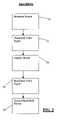
- FIG. 1is a flow chart of the method of encoding of the present invention.
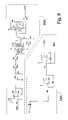
- FIG. 2is a flow chart of the method of decoding of the present invention.
- FIG. 3is a block diagram of the decoder of the present invention.
- FIG. 4is a an alternate embodiment of the method of decoding of the present invention.
- FIG. 5is a block diagram of the encoder of the present invention.
- FIG. 6is a schematic circuit arrangement of one embodiment of the hand-held device of the present invention.
- FIG. 7is a schematic circuit diagram of an analog pre-filter of the data decoder of the invention.
- FIG. 8is a schematic circuit diagram of analog vertical synch and signal strength detection of the data decoder of the invention.
- FIG. 9is a schematic circuit diagram of data signal detection circuitry of the data decoder of the invention.
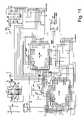
- FIG. 10is a schematic circuit diagram of a microcontroller of a first embodiment of the data decoder of the invention.
- FIG. 11is a schematic circuit diagram of a microcontroller of a second embodiment of the data decoder of the invention.
- FIG. 12is a flow chart of the method of decoding of the present invention.
- FIG. 13is a graphic representation of the fields of the present invention.
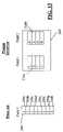
- FIG. 14is a graphic representation of a data packet used in the present invention.
- Broughtondiscloses a communication system that allows auxiliary data to be received from a display device, wherein the data is preferably read optically by a hand-held device through use of a photodetector.
- a video signal 18is transmitted from a signal source 10 to an encoder 12 .
- Video signal 18is preferably an analog NTSC video signal, but may be other video signals or video signal formats compatible with the present invention.
- Signal source 10is typically a professional grade video tape player with a video tape containing a video program, but may also be other sources of video signals including a camcorder or a digital versatile disc (DVD) player with a DVD video containing a program.
- Encoder 12is described in further detail in the description of FIG. 5 below.
- Operator 16interacts with encoder 12 to control its operation.
- operator 16is a person that interacts with encoder 12 through the use of a computer or other electronic control device.
- operator 16may consist entirely of a computer or other electronic control device that directs operation of encoder 12 in an automated manner.
- a carrier signal 20is selectively added to video signal 18 by operator 16 at encoder 12 to modulate auxiliary data 21 within video signal 18 .
- the method of adding carrier signal 20is by selectively increasing and decreasing pixel intensity of paired scan lines as disclosed in Broughton.
- the present encoding methoddiffers from Broughton in that encoder 12 splits each field of video signal 18 into multiple segments, such that each segment may be individually modulated with carrier signal 20 and the complement of the data bit broadcast on the first field is modulated on the second field, as will be described in further detail below.
- the present method of selectively modulatingcan reverse the order of the fields (i.e., the first field and second field) as needed or desired in a particular embodiment.
- the present inventionutilizes four equal segments per field.
- encoder 12Upon modulating video signal 18 , encoder 12 outputs a modulated video signal 22 comprised of video signal 18 and auxiliary data 21 (i.e., a composite video signal). Modulated video signal 22 is then provided to a broadcast source 14 for distribution to end-users who will view the program.
- Broadcast source 14is preferably a television broadcast station that broadcasts programs, but also may be other broadcast video sources and DVD media and other media sources including video tapes that will be provided to one or more end users.
- broadcast source 14provides modulated video signal 22 to display device 26 .
- Display device 26is representative of a television screen, video monitor or other video display, movie screen, computer monitor, video-converted display or video-like display, capable of receiving analog or digital video or video-representative signals from a suitable signal source, such as a television transmitter, a videotape, a streaming video server, a DVD, or the computerized display representation of such a source of image content.
- a suitable signal sourcesuch as a television transmitter, a videotape, a streaming video server, a DVD, or the computerized display representation of such a source of image content.
- display device 26is a kinescope or other conventional type of television display or monitor (which may include multiple or single-beam types of projector displays).
- Display device 26may schematically represent a video display for displaying video signals 18 but may also be any sort of electron gun, active, array or passive array display device capable of providing not only imaged information in a visible mode but also auxiliary information (e.g., data) in a substantially transparent mode.
- Display device 26may be further characterized as a computer monitor or display, as well as a portion or computer window of display device 26 .
- Display device 26may also be a high definition or digital television, or other digital video presentation device.
- Display device 26may vary in size, and may be small like a Sony® Watchman®, or large like a movie screen or a Sony Jumbotron®.
- Video signals 18 receivable from broadcast source 14 by display device 26include those delivered by microwave relay, satellite retransmission or cable, streaming and other types of downloadable or viewable computer video presentations, and those generally made available by wired or wireless methods.
- Modulated video signal 22is presented on display device 26 .
- Slotted hand-held device 29optically receives modulated video signal 22 by use of a photodetector 62 on an interface card 60 .
- Slotted hand-held device 29may be in the form of any type of hand manipulable device such as a smart card, cell phone, PDA, game unit or other palm like device that has a slot 66 .
- Slotted hand-held device 29may be held in the palm or between the fingers of a user in the general vicinity of display device 26 , typically within the same room and, when necessary, oriented so that photodetector 62 may optically receive light from a visual representation of modulated video signal 22 from display device 26 .
- photodetector 62 , interface card 60 , data decoder 72 and slotted hand-held device 29may alternatively be combined in a non-slotted hand-held device 28 such as used in Koplar I.
- a slotted hand-held device 29such as a PDA, game unit, or cellular telephone is outfitted with a slot 66 and contains software and/or other electronics to run an interface protocol 68 .
- the present inventionmay be used with various interface cards 60 and slots 66 provided that device 29 uses an interface protocol 68 that allows for expansive use of its protocol (i.e., an “open protocol”) with card 60 and slot 66 .
- slot 66is a SD slot and interface protocol 68 is the SDIO protocol.
- An interface card 60also operating interface protocol 68 is inserted into slotted hand-held device 29 , and device 29 runs software to interpret data received by card 60 and passes it to device 29 by use of interface protocol 68 .
- modulated video signal 22comprised of video signal 20 and auxiliary data 21 , is transmitted from display device 26 and detected by photodetector 62 on interface card 60 . Thereafter, the received modulated video signal 22 is decoded by a data decoder 72 located on interface card 60 . The decoded auxiliary data 21 is passed to slotted hand-held device 29 through use of an interface protocol 68 . Slotted hand-held device 29 utilizes auxiliary data 21 to provide the user with a benefit or promotional opportunities based on the receipt of auxiliary data 21 . The promotional opportunities may be redeemed or obtained using the optional wireless Internet access 70 , as described in Koplar I.
- the slotted hand-held device 29preferably uses wireless Internet access 70 to provide and/or redeem promotional opportunities over the Internet.
- the preferred protocol for wireless Internet accessis the use of Bluetooth.
- Bluetoothprovides a means for RF data to be passed in a specified form at a 2.4 GHz frequency between slotted hand-held device 29 and a transceiver that is connected to the Internet. It will be appreciated in the art of Internet networking that other means of providing wired and wireless Internet may be used with the present invention including Wifi 802.11.
- interface card 60may, in addition to or an alternative of photodetector 62 , receive modulated video signal 22 or auxiliary data 21 by other means including by use of a RF receiver such as when broadcast source 14 is a decoder box that demodulates the modulated video signals and transmits auxiliary data 21 by various methods known in the art of signal transmission including RF.
- a RF receiversuch as when broadcast source 14 is a decoder box that demodulates the modulated video signals and transmits auxiliary data 21 by various methods known in the art of signal transmission including RF.
- data storagemay be added to interface card 60 to store auxiliary data 21 or promotional opportunities for later recall. It should be appreciated that, depending on the application, it may be desirable to provide a large amount of space on interface card 60 thereby allowing a significant amount of data to be stored and later retrieved.
- FIG. 4shows electrical detection of auxiliary data 21 .
- Broadcast source 14provides modulated video signal 22 to a decoder 13 .
- decoder 13acts in a similar manner to data decoder 72 by determining whether auxiliary data 21 is present in modulated video signal 22 but also contains transmission device 24 and a video output to provide the modulated video signal 22 to a display device 26 .
- Auxiliary data 21is provided to a transmission device 24 , which transfers the information to a non-slotted hand-held device 28 without a photodetector 62 but with a non-optical receiver 64 such as RF receivers, infrared and computer-like interconnections.
- Modulated video signal 22is passed unaltered through decoder 13 and out the video output and presented on display device 26 so that a user may watch the video program.
- non-slotted hand-held device 28Upon receipt of auxiliary data 21 , non-slotted hand-held device 28 provides the user with a benefit or promotional opportunity.
- non-optical receiver 64may be implemented on interface card 60 such that slotted hand-held device 29 replaces non-slotted hand-held device 28 and acts in a manner consistent with the foregoing description.
- Encoder 12 in FIG. 5includes a digital video input 30 to receive a video signal 18 from signal source 10 and to pass it to micro-controller 36 .
- encoder 12may receive an analog video signal 18 via analog video input 32 and analog to digital converter 34 .
- Analog to digital converter 34digitizes the analog video signal 18 according to known techniques such that it may be sent to micro-controller 36 .
- Micro-controller 36is electronically connected to a carrier presence 38 , which provides micro-controller 36 with the timing of where, when and at what intensity encoder 12 should insert carrier signal 20 into video signal 18 at the direction of operator 16 .
- a carrier presence 38Preferably, such instructions are received from operator 16 by carrier presence 38 via a serial port.
- carrier presence 38may be an operator interface so that operator 16 can directly interface with encoder 12 .
- micro-controller 36receives video signal 18 and information from carrier presence 38
- software 50manages further operation of encoder 12 and directs micro-controller 36 to store the chrominance information of video signal 18 in storage 40 .
- Encoder electronics 42 at the direction of software 50preferably uses the methods of Broughton and the present invention as will be described in further detail below to modulate carrier signal 20 into the luminance of video signal 18 thereby creating modulated video signal 22 .
- the resulting modulated video signal 22is then sent digitally from encoder 12 by digital video output 44 , or in analog form by converting the resulting digital signal with digital to analog converter 46 and outputting modulated video signal 22 by analog video output 48 .
- Micro-controller 36may consist of more than one processor to manage the various processing and input/output of the present invention, but preferably consists of a single processor. Moreover, the specific electronics and software used by encoder 12 may differ when its technology is included in a pre-existing device as opposed to a stand alone device. Encoder 12 may comprise varying degrees of hardware and software, as various components may interchangeably be used as either.
- FIG. 6shows an overview of the preferred embodiment of a microcontroller 100 and device circuitry 102 of data decoder 32 .
- Device circuitry 102is comprised of an analog pre-filter 104 , a vertical detect/signal strength circuitry 106 and an auxiliary data detector 108 , all of which are operatively associated with each other and microcontroller 100 as shown.
- the preferred embodiment of analog pre-filter 104 that prepares the circuit for accurate digitizationfirst comprises a current voltage converter 300 .
- Current voltage converter 300first comprises a photodetector D 200 , which optically reads a video signal 18 from display device 26 and outputs a current to voltage converter 300 . Thereafter, current voltage converter 300 transforms the current detected by photodetector D 200 into voltage.
- the circuitry of voltage converter 300further comprises three resistors, R 200 , R 201 and R 202 , three capacitors C 200 , C 201 and C 202 , an operational amplifier U 200 and voltages VA and VCC, all of which are operatively associated as shown.
- An automatic gain control 310 portion of analog prefilter 104amplifies video signal 18 by changing the resistance on the feedback circuit.
- the amount of gain provided to the circuitis controlled by microcontroller 100 .
- Automatic gain control 310is used with interface card 60 as the distance and intensities received from display device 26 will vary. Accordingly, when the strength of video signal 18 is low, it is desirable to add gain so that a better reading of video signal 18 is possible. Therefore, the present invention measures the signal strength and decides whether to lower or increase the gain.
- the components of automatic gain control 310include resistors R 203 , R 208 and R 209 , capacitor C 212 , voltages VA and VCC an operational amplifier U 400 C and a digital potentiometer U 204 , all of which are operatively associated as shown.
- Video signal 18passes from automatic gain control 310 to low pass filter—80 KHz cutoff 320 .
- This circuitprovides a low pass filter that removes the high frequency noise from the signal by eliminating all frequencies above a preset level (i.e., 80 kilohertz).
- the components of the low pass filter—80 KHz cutoff 320include resistors R 210 , R 204 and R 205 , capacitors C 203 , C 204 , and C 206 , voltages VA and VCC and operational amplifier U 201 , all of which are operatively associated as shown.
- Video signal 18then passes from the low pass filter—80 KHz cutoff 320 to the high pass filter 7 KHz cutoff 330 .
- High pass filter 7 KHz cutoff 330cleans the signal below 7 KHZ by discarding the undesired signal.
- the components of the high pass filter—7 KHz cutoff 330include resistors R 206 and R 207 , capacitors C 207 , C 208 , C 209 , C 210 and C 211 , voltages VA and VCC and operational amplifier U 201 , all of which are operatively associated as shown.
- the circuitry of vertical detect/signal strength circuitry 106 in the preferred embodimentcomprises a signal strength detector 340 and an analog vertical sync 350 .
- Signal strength detector 340first comprises a rectifier D 300 that polarizes video signal 18 . Thereafter, video signal 18 transitions through a buffer comprised of resistor R 306 and R 307 , voltage VA, and operational amplifier U 300 B to invert the signal.
- the last portion of this circuitis an integrator, which measures the strength of video signal 18 and is comprised of resistor R 308 , capacitor R 305 , voltage VA and operational amplifier U 300 C, all of which are operatively associated as shown.
- the output of the integratoris signal SSRES 1 and is received by microcontroller 100 which then resets the signal strength integrator.
- the signal for analog vertical sync 350is passed from low pass filter—80 KHz cutoff 320 .
- Analog vertical sync 350generates the desired vertical synchronization signal used to synchronize the reading of data bits from auxiliary data 21 .
- the first part of circuitryis a gaining amplifier that gains the signal and inverts it by use of resistor R 300 and R 301 , capacitor C 300 , voltage VA and gate U 300 D.
- the second part of the circuitryprovides a small filtering stage. Resistors R 302 and R 303 and capacitor C 301 filter high spikes out of the signal.
- the signalis processed by schmitt trigger inverters U 302 A and U 302 D, the double inversion acting as a buffer. Because of the nature of the schmitt trigger, voltage spikes are removed from the signal. Thereafter, the signal triggers a flip flop 74 HC 74 .
- the output of the flip flop 74 HC 74triggers a 555 timer 555 , which is used to generate a constant timed pulse. During each pulse, regardless of how many triggers the 555 timer 555 receives, it will not generate interloping pulses until it times out.
- Resistor R 305may be used to adjust the time constant, by which the pulse can become wider or narrower. If microcontroller 100 detects the pulse and then waits for another vertical retrace period (i.e., 16.67 milliseconds) and detects the pulse again, it knows that it has locked on the vertical synchronization signal.
- the pre-filter signalis passed to a horizontal notch filter 360 that removes video signal 18 at the horizontal line scanning rate (i.e., 15570 KHz) from modulated video signal 22 so that it does not interfere with the reading of auxiliary data 21 .
- low pass filter with cutoff at VEIL Freq. 370is used for extra filtering to ensure that the signal higher than the 8 kilohertz is discarded.
- the signalis passed to a band pass filter 380 which is another stage of filtering around 8 kilohertz.
- the signalthen goes through a signal rectifier 390 that acts as an integrator that has a gain of one.
- the signaltravels through a VEIL signal energy integrator 400 that measures the strength of the signal by measuring its voltage.
- the aforementioned circuitsconsists of a number of resistors R 400 -R 413 , capacitors C 400 - 410 , voltages VA and VCC, and operational amplifiers U 400 A, U 400 B, U 400 D, U 401 D, U 401 C, and U 401 B, all of which are operatively associated as shown.
- microcontroller 100 and associated circuitry as would be used in a first version of the combination of slotted-hand device 29 , data decoder 72 and interface card 60 in a non-slotted hand-held device 28 with photodetector 62first comprises a power source consisting of four batteries BC 500 , BC 501 , BC 502 and BC 503 . Each battery is 1.5 volts, and the power is provided to voltage regulator U 501 . Voltage regulator U 501 provides microcontroller 100 with a steady 5 volts of power through D 501 . VCC and VA are also provided by voltage regulator U 501 , wherein by means of a voltage divider VA is 2% volts and VCC is 5 volts. VCC is being fed through a diode D 501 that provides battery voltage.
- Diode D 501allows microcontroller 100 to go into a sleep mode so as to reduce its need for voltage. When microcontroller 100 wants to sleep, it can shut of voltage regulator U 501 and go into sleep mode. Dual analog switch MAX 323 is used to reset both the signal strength integrator and the VEIL signal strength integrator via the microcontroller 100 .
- speaker SPK 1is speaker SPK 1 , transistor Q 504 , visual display U 503 , switches S 500 , S 501 , S 502 , S 503 and S 504 , and interface b 232 , all of which are operatively associated as shown and the use of which are in accordance with the present invention as well as the hand-held devices described in Koplar I, Koplar II and Withers.
- microcontroller 100 in FIG. 11is shown as implemented on interface card 60 .
- Microcontroller 100is shown in this preferred embodiment to be comprised of two separate microcontrollers U 500 and U 503 , of which microcontroller U 500 controls the operations of microcontroller 100 as described in FIG. 10 above such as optical detection and determining whether auxiliary data 21 is present in video signal 18 , and microcontroller U 503 manages the interface with slot 66 (i.e., SDIO connector J 501 ).
- SDIO connector J 501communicates with interface card 60 as described below.
- Microcontroller U 503further controls the communication between the optical and SD portions of the circuitry.
- microcontroller U 503runs at 8 MHz while microcontroller U 500 runs at 4 MHz.
- Port RS 232is a computer interface which may optionally be included in various embodiments such as to debug the system to ensure that the proper auxiliary data is being received and modulated on interface card 60 .
- Integrated circuit Max 232allows interface card 60 to communicate via a computer port RS 232 so that interface card 60 may directly interact with a computer such as for debugging purposes.
- a power sourceis not needed on interface card 60 as power is provided through slot 66 .
- a charge pump U 504changes the three volts received from slot 66 into five volts so as to properly power interface card 60 .
- a userorients or connects a receiver, such as slotted hand-held device 29 , towards or in connection with a display device 26 for the purpose of capturing modulated video signals 28 .
- a video signal 18is captured from display device 26 by a photodetector 30 of interface card 60 .
- a microcontroller 100 and device circuitry 104amplify, filter and shape video signal 18 received during a third step 1200 .
- microcontroller 100determines whether auxiliary data 21 is present in video signal 18 (i.e., whether video signal 18 is modulated video signal 22 ). If there is no auxiliary data 21 present in video signal 18 , the method returns to second step 1100 and again attempts to capture modulated video signal 22 . If in fourth step 1300 microcontroller 100 determines that auxiliary data 21 is present, then the method proceeds to a fifth step 1400 wherein microcontroller 100 determines whether a complete data packet 112 has been received by interface card 60 . If auxiliary data 21 is not in the form of data packet 112 or is otherwise unusable, auxiliary data 21 is discarded and the method returns to second step 1100 .
- microcontroller 100determines the total number of packets 114 that interface card 60 expects to receive and the identification of a data packet number 116 of the just received data packet 112 . If the total number of packets 114 to be received by interface card 60 is 1, then microcontroller 100 takes further action necessary to provide the user of slotted hand-held device 29 with a benefit as a result of receiving all of the desired auxiliary data 21 (e.g., promotional opportunities) as disclosed in a ninth step 1800 . If total number of packets 114 is greater than 1, then microcontroller 100 proceeds to an eighth step 1700 whereby microcontroller 100 determines whether every data packet 112 corresponding to each data packet number 116 has been captured.
- interface card 60returns to the second step 1100 so as to attempt to capture the missing data packets 112 . If all data packets 112 have been captured, slotted hand-held device 29 proceeds to provide the promotional opportunities to the user according to ninth step 1800 .
- a user of slotted hand-held device 29receives promotional opportunities or other benefits that may include textual information, prizes, coupons, games, special access privileges, etc. Thereafter, the method of the present invention is terminated during a final step 1900 .
- Broughton's methodinvolves encoding each portion of a field 200 with an identical bit. As shown in FIG. 13 , every slice 200 a - h of field 200 contains the bit “ 1 ”.
- fields 210 a and 210 b of a frame 220are encoded with complementary bits.
- a logic “1”is encoded in two fields 210 a and 210 b as “1 0”
- a logic “0”is encoded in two fields 210 a and 210 b as “0 1”.
- interface card 60receives the bits, it performs a field comparison by subtracting the result of the intensity of two successive fields 210 a and 210 b . This method produces a reliable data rate of 30 bits per second.
- the speed of the present inventionis increased by splitting every field 210 into multiple segments with each portion having its own respective bit.
- each field 210is split into four equal portions such that each portions is at an equal offset from one another.
- fields 210 a and 210 b splitsappear in FIG. 13 with the 4 data bits decoded as “1 0 1 1”. This method of splitting the fields produces a reliable rate of 120 bits per second data.
- microcontroller 100needs to determine where fields 210 a and 210 b begin during decoding so that it can properly obtain all of the bits.
- data decoder 32obtains its proper timing by looking for and synchronizing to the vertical retrace period in video signal 20 .
- microcontroller 100first looks for a section of the picture presented on display device 26 that is completely black (i.e., no video) and therefore may be a vertical retrace signal indicating that a vertical refresh of the picture has occurred. Thereafter, microcontroller 100 waits a sufficient time for another vertical refresh to occur (i.e., 16.67 milliseconds). If microcontroller 100 reads two successive regions that are completely black, and they are 16.67 milliseconds apart, microcontroller 100 acts under the belief that it has locked on the vertical retrace signal and continues to read and record data packets 112 at a preferred displacement of 2 milliseconds from the beginning of the vertical retrace signal. If during the foregoing synchronization process data decoder 32 fails to detect a first and a second black region, it will continue attempting to synchronize by searching for black regions that are 16.67 milliseconds apart beyond where it previously looked.
- data decoder 32is then in synchronization with video signal 18 and temporarily stops looking for the vertical retrace signal.
- video signal 18 locking of the present inventiondata decoder 32 locks on the vertical retrace signal for a few seconds and thereafter releases it and the synchronization process starts over again.
- Re-detection and re-synchronization of the present invention in this embodimentis preferred because timing of microcontroller 100 is not entirely accurate, therefore causing the synchronization of the vertical retrace signal to drift after a few seconds and making it more difficult to detect valid auxiliary data 21 .
- auxiliary data 21is determined by looking for a sync.
- Data decoder 32looks for a first data bit in data packet 112 , such as A5, that acts as a marker or preamble. Data decoder 32 drifts very slowly across display device 26 trying to capture the marker, then data decoder 32 acts as though it is at the start of data packet 112 and sequentially reads the various bits. The data bits are read sequentially and then shifted in a register to its left, so that data decoder 32 receives the A5 byte first. Once a valid data packet 112 is received, then data decoder 32 is perfectly synced and can continue to read successive data packets 112 . Data decoder 32 is ensured of a valid data packet 112 by checking the CRC byte of data packet 112 .
- Auxiliary data 21is read by microcontroller 32 in data packets 112 of preferably 8 bytes (i.e., 64 bits) in length.
- data packet 112first comprises a first byte 250 containing a preamble that identifies it as the start of data packet 112 .
- a second byte 252contains the data packet number 26 relative to the total number of packets sent 25 (i.e., packet is 2 of 5).
- the following five bytes 254 , 256 , 258 , 260 and 262i.e., bytes 3 - 7 ) contain actual data, which may be compressed as will be readily understood by someone skilled in the art of data compression.
- the final byte 264contains a Cyclic Redundancy Check (CRC) to ensure that the received data bytes 250 - 262 were precisely matched with those transmitted from the signal source.
- CRCCyclic Redundancy Check
- Data packets 112 of a message 118are typically sent by broadcast source 14 more than one time as will be appreciated in the art of computer networking.
- Message 118 in the preferred embodimentmay contain up to 16 data packets 112 .
- Data packets 112may be received by slotted hand-held device 29 or other receiver in any order, and any data packets 112 that have previously been successfully captured by slotted hand-held device 29 will be ignored. Once all data packets 112 have been correctly received by slotted hand-held device 29 , the entire message 118 is then declared to have been successfully decoded, and slotted hand-held device 29 takes appropriate action by providing the user with a benefit or one or more other promotional opportunities.
Landscapes
- Engineering & Computer Science (AREA)
- Signal Processing (AREA)
- Multimedia (AREA)
- Business, Economics & Management (AREA)
- Computer Networks & Wireless Communication (AREA)
- Strategic Management (AREA)
- Accounting & Taxation (AREA)
- Development Economics (AREA)
- General Engineering & Computer Science (AREA)
- Finance (AREA)
- Marketing (AREA)
- Theoretical Computer Science (AREA)
- Economics (AREA)
- Software Systems (AREA)
- Physics & Mathematics (AREA)
- General Business, Economics & Management (AREA)
- General Physics & Mathematics (AREA)
- Game Theory and Decision Science (AREA)
- Entrepreneurship & Innovation (AREA)
- Controls And Circuits For Display Device (AREA)
- Television Systems (AREA)
- Two-Way Televisions, Distribution Of Moving Picture Or The Like (AREA)
- Details Of Television Systems (AREA)
- Mobile Radio Communication Systems (AREA)
Abstract
Description
Claims (15)
Priority Applications (7)
| Application Number | Priority Date | Filing Date | Title |
|---|---|---|---|
| US10/676,940US7650624B2 (en) | 2002-10-01 | 2003-10-01 | Method and apparatus for modulating a video signal with data |
| JP2004290220AJP2005167986A (en) | 2003-10-01 | 2004-10-01 | Method and apparatus for modulating video signal with data |
| EP04077707AEP1521464A3 (en) | 2003-10-01 | 2004-10-01 | Method and apparatus for modulating a video signal with data |
| KR1020040078258AKR20050032487A (en) | 2003-10-01 | 2004-10-01 | Method and apparatus for modulating a video signal with data |
| CA002483492ACA2483492A1 (en) | 2003-10-01 | 2004-10-01 | Method and apparatus for modulating a video signal with data |
| US12/630,970US7900236B2 (en) | 2002-10-01 | 2009-12-04 | Method and apparatus for modulating a video signal with data |
| US12/771,571US10511877B2 (en) | 2002-10-01 | 2010-04-30 | Method and apparatus for modulating a video signal with data |
Applications Claiming Priority (2)
| Application Number | Priority Date | Filing Date | Title |
|---|---|---|---|
| US41503402P | 2002-10-01 | 2002-10-01 | |
| US10/676,940US7650624B2 (en) | 2002-10-01 | 2003-10-01 | Method and apparatus for modulating a video signal with data |
Related Parent Applications (1)
| Application Number | Title | Priority Date | Filing Date |
|---|---|---|---|
| US41503402PDivision | 2002-10-01 | 2002-10-01 |
Related Child Applications (1)
| Application Number | Title | Priority Date | Filing Date |
|---|---|---|---|
| US12/630,970ContinuationUS7900236B2 (en) | 2002-10-01 | 2009-12-04 | Method and apparatus for modulating a video signal with data |
Publications (2)
| Publication Number | Publication Date |
|---|---|
| US20040117856A1 US20040117856A1 (en) | 2004-06-17 |
| US7650624B2true US7650624B2 (en) | 2010-01-19 |
Family
ID=34314043
Family Applications (3)
| Application Number | Title | Priority Date | Filing Date |
|---|---|---|---|
| US10/676,940Active - Reinstated2026-09-17US7650624B2 (en) | 2002-10-01 | 2003-10-01 | Method and apparatus for modulating a video signal with data |
| US12/630,970Expired - LifetimeUS7900236B2 (en) | 2002-10-01 | 2009-12-04 | Method and apparatus for modulating a video signal with data |
| US12/771,571Expired - Fee RelatedUS10511877B2 (en) | 2002-10-01 | 2010-04-30 | Method and apparatus for modulating a video signal with data |
Family Applications After (2)
| Application Number | Title | Priority Date | Filing Date |
|---|---|---|---|
| US12/630,970Expired - LifetimeUS7900236B2 (en) | 2002-10-01 | 2009-12-04 | Method and apparatus for modulating a video signal with data |
| US12/771,571Expired - Fee RelatedUS10511877B2 (en) | 2002-10-01 | 2010-04-30 | Method and apparatus for modulating a video signal with data |
Country Status (5)
| Country | Link |
|---|---|
| US (3) | US7650624B2 (en) |
| EP (1) | EP1521464A3 (en) |
| JP (1) | JP2005167986A (en) |
| KR (1) | KR20050032487A (en) |
| CA (1) | CA2483492A1 (en) |
Cited By (14)
| Publication number | Priority date | Publication date | Assignee | Title |
|---|---|---|---|---|
| US20070035662A1 (en)* | 2005-08-11 | 2007-02-15 | Mario Maracic | Method, System, and Apparatus for Communication by Means of Transmitted Signals Over Visual Media |
| US20070276670A1 (en)* | 2006-05-26 | 2007-11-29 | Larry Pearlstein | Systems, methods, and apparatus for synchronization of audio and video signals |
| US20100050082A1 (en)* | 2008-08-22 | 2010-02-25 | Pvi Virtual Media Services, Llc | Interactive Video Insertions, And Applications Thereof |
| US20100141836A1 (en)* | 2003-08-26 | 2010-06-10 | Koplar Interactive Systems International, Llc | Method and system for enhanced modulation of video signals |
| US20100263013A1 (en)* | 2007-11-27 | 2010-10-14 | Nec Corporation | Content distribution system, content distribution server, content distribution method, and content distribution program |
| US20130219449A1 (en)* | 2012-02-21 | 2013-08-22 | Ranga Muvavarirwa | Remote media streaming |
| US8713604B2 (en) | 2010-06-23 | 2014-04-29 | Echostar Technologies L.L.C. | Systems and methods for processing supplemental information associated with media programming |
| US20160093011A1 (en)* | 2010-06-23 | 2016-03-31 | Digimarc Corporation | Detecting encoded signals under adverse lighting conditions using adaptive signal detection |
| US20190155845A1 (en)* | 2016-07-01 | 2019-05-23 | Sagemcom Broadband Sas | Method for storing a multimedia content, associated reading method and method for managing a storage space containing such a content |
| US11544748B2 (en) | 2017-10-26 | 2023-01-03 | Advocado, Inc | Online advertising and promotional coordination system |
| US20230188687A1 (en)* | 2020-05-21 | 2023-06-15 | Sony Group Corporation | Image display apparatus, method for generating trained neural network model, and computer program |
| US12155976B2 (en)* | 2021-11-29 | 2024-11-26 | Lumileds Llc | Projector with local dimming |
| US20250008078A1 (en)* | 2023-06-29 | 2025-01-02 | GM Global Technology Operations LLC | Polarization-based optical arrangement with virtual displays and multiple fields of view |
| US12289490B2 (en)* | 2022-11-17 | 2025-04-29 | Lilac Cloud, Inc. | Application cache acceleration using device content cache |
Families Citing this family (23)
| Publication number | Priority date | Publication date | Assignee | Title |
|---|---|---|---|---|
| US7650624B2 (en) | 2002-10-01 | 2010-01-19 | Koplar Interactive Systems International, L.L.C. | Method and apparatus for modulating a video signal with data |
| US7197583B2 (en)* | 2003-01-21 | 2007-03-27 | Zentek Technology Japan, Inc. | SDIO controller |
| US7330511B2 (en)* | 2003-08-18 | 2008-02-12 | Koplar Interactive Systems International, L.L.C. | Method and system for embedding device positional data in video signals |
| JP2005117447A (en)* | 2003-10-09 | 2005-04-28 | Nec Corp | Movie recording apparatus, movie recording method, and movie recording program |
| US7075583B2 (en)* | 2003-10-20 | 2006-07-11 | Koplar Interactive Systems International, L.L.C. | Methods for improved modulation of video signals |
| US7830357B2 (en)* | 2004-07-28 | 2010-11-09 | Panasonic Corporation | Image display device and image display system |
| US7826674B1 (en) | 2004-09-10 | 2010-11-02 | Koplar Interactive Systems International, L.L.C. | Content signal analysis |
| US20070153025A1 (en)* | 2005-12-29 | 2007-07-05 | Mitchell Owen R | Method, apparatus, and system for encoding and decoding a signal on a viewable portion of a video |
| WO2008025824A1 (en)* | 2006-08-31 | 2008-03-06 | Siemens Enterprise Communications Gmbh & Co. Kg | Method for secured transmission of digital information by means of optical information |
| KR100838575B1 (en) | 2007-01-15 | 2008-06-19 | 주식회사 대우일렉트로닉스 | Noise reduction circuit of LCD TV |
| US9015741B2 (en) | 2009-04-17 | 2015-04-21 | Gracenote, Inc. | Method and system for remotely controlling consumer electronic devices |
| US8189340B2 (en) | 2009-06-24 | 2012-05-29 | Ivs, Inc. | Mobile digital video recorder |
| US9277183B2 (en)* | 2009-10-13 | 2016-03-01 | Sony Corporation | System and method for distributing auxiliary data embedded in video data |
| US20130009969A1 (en)* | 2011-07-05 | 2013-01-10 | Netanel Goldberg | Methods circuits & systems for wireless transmission of a video signal from a computing platform |
| US8599311B2 (en)* | 2011-07-14 | 2013-12-03 | Amimon Ltd. | Methods circuits devices and systems for transmission and display of video |
| CN103607559A (en)* | 2013-11-07 | 2014-02-26 | 成都斯科瑞特科技有限公司 | Communication method of video file, monitoring terminal, monitoring server and video monitoring system |
| US20160065647A1 (en)* | 2014-08-26 | 2016-03-03 | Sandeep VENKATESH | System and method for enabling downloading of files |
| WO2016047030A1 (en)* | 2014-09-26 | 2016-03-31 | パナソニックIpマネジメント株式会社 | Display apparatus and display method |
| US10945033B2 (en)* | 2018-03-14 | 2021-03-09 | Idomoo Ltd. | System and method to generate a customized, parameter-based video |
| US10904637B2 (en)* | 2018-12-17 | 2021-01-26 | Qualcomm Incorporated | Embedded rendering engine for media data |
| CN110428788A (en)* | 2019-07-24 | 2019-11-08 | 深圳市华星光电技术有限公司 | A kind of the common voltage compensation circuit and compensation system of display panel |
| US11865434B2 (en)* | 2019-10-01 | 2024-01-09 | Sony Interactive Entertainment Inc. | Reducing latency in cloud gaming applications by overlapping receive and decode of video frames and their display at the client |
| US11288212B2 (en)* | 2019-12-18 | 2022-03-29 | Samsung Electronics Co., Ltd. | System, apparatus, and method for secure deduplication |
Citations (60)
| Publication number | Priority date | Publication date | Assignee | Title |
|---|---|---|---|---|
| US3493674A (en) | 1965-05-28 | 1970-02-03 | Rca Corp | Television message system for transmitting auxiliary information during the vertical blanking interval of each television field |
| US3993861A (en) | 1975-03-24 | 1976-11-23 | Sanders Associates, Inc. | Digital video modulation and demodulation system |
| US4101927A (en) | 1975-12-27 | 1978-07-18 | Sony Corporation | Vir control apparatus for color television receiver |
| US4186413A (en) | 1977-11-14 | 1980-01-29 | Sanders Associates, Inc. | Apparatus for receiving encoded messages on the screen of a television receiver and for redisplay thereof on the same receiver screen in a readable format |
| US4642682A (en) | 1984-04-27 | 1987-02-10 | Vta Technologies, Inc. | Phase responsive composite video signal control system |
| US4654700A (en) | 1985-04-01 | 1987-03-31 | Sanders Associates, Inc. | Optical decoder |
| US4688102A (en) | 1982-11-11 | 1987-08-18 | Canon Kabushiki Kaisha | Color video signal mixing system |
| US4691245A (en) | 1984-12-03 | 1987-09-01 | Eastman Kodak Company | Method and apparatus for combining two color video signals |
| US4807031A (en)* | 1987-10-20 | 1989-02-21 | Interactive Systems, Incorporated | Interactive video method and apparatus |
| US5010499A (en) | 1988-02-22 | 1991-04-23 | Yee Keen Y | Digital data capture for use with TV set or monitor |
| US5057915A (en) | 1986-03-10 | 1991-10-15 | Kohorn H Von | System and method for attracting shoppers to sales outlets |
| US5325127A (en) | 1989-12-22 | 1994-06-28 | Telefunken | Process for transmitting digital data, in particular sound data, in a TV channel |
| US5423555A (en) | 1993-04-14 | 1995-06-13 | Kidrin; Thom | Interactive television and video game system |
| US5461426A (en) | 1993-08-20 | 1995-10-24 | Samsung Electronics Co., Ltd. | Apparatus for processing modified NTSC television signals, with digital signals buried therewithin |
| US5510845A (en) | 1994-12-23 | 1996-04-23 | Samsung Electronics Co., Ltd. | Receivers for digital signals buried within the trace and retrace intervals of NTSC television signals |
| US5526035A (en) | 1991-11-20 | 1996-06-11 | Zing Systems, L.P. | Transaction based interactive television system |
| US5550578A (en) | 1990-09-28 | 1996-08-27 | Ictv, Inc. | Interactive and conventional television information system |
| US5555024A (en) | 1994-12-23 | 1996-09-10 | Samsung Electronics Co., Ltd. | Transmitters for burying digital signals within the trace and retrace intervals of NTSC television signals |
| US5557333A (en) | 1991-06-14 | 1996-09-17 | Wavephore, Inc. | System for transparent transmission and reception of a secondary data signal with a video signal in the video band |
| US5557334A (en) | 1993-01-12 | 1996-09-17 | Visual Automation Systems, Inc. | Apparatus for tracking the flow of video signals by incorporating patterns of machine readable signals which will appear at predetermined locations of a television picture |
| US5561467A (en) | 1990-03-26 | 1996-10-01 | Nippon Hoso Kyokai | Receiver and channel compatible encoding/decoding system for high definition video |
| US5587743A (en) | 1991-06-14 | 1996-12-24 | Wavephore, Inc. | Signal processors for transparent and simultaneous transmission and reception of a data signal in a video signal |
| US5594493A (en) | 1994-01-19 | 1997-01-14 | Nemirofsky; Frank R. | Television signal activated interactive smart card system |
| US5708476A (en) | 1994-05-03 | 1998-01-13 | Microsoft Corporation | System and method for inserting and recovering a data signal for transmission with a video signal |
| US5737417A (en) | 1995-04-24 | 1998-04-07 | Technicolor Videocassette, Inc. | Videotape anti-copying encryption scheme |
| US5739866A (en) | 1994-05-03 | 1998-04-14 | Microsoft Corporation | System and method for inserting and recovering an on data signal for transmission with a video signal |
| US5808689A (en) | 1994-04-20 | 1998-09-15 | Shoot The Moon Products, Inc. | Method and apparatus for nesting secondary signals within a television signal |
| US5831679A (en) | 1991-06-14 | 1998-11-03 | Wavephore, Inc. | Network for retrieval and video transmission of information |
| US5929920A (en) | 1996-01-25 | 1999-07-27 | Lucent Technologies Inc. | System and method for encoding digital information in a television signal |
| US6072521A (en) | 1995-06-15 | 2000-06-06 | Intel Corporation | Hand held apparatus for simulating two way connectivity for one way data streams |
| US6091822A (en) | 1998-01-08 | 2000-07-18 | Macrovision Corporation | Method and apparatus for recording scrambled video audio signals and playing back said video signal, descrambled, within a secure environment |
| US6094228A (en) | 1997-10-28 | 2000-07-25 | Ciardullo; Daniel Andrew | Method for transmitting data on viewable portion of a video signal |
| US6097877A (en) | 1994-05-20 | 2000-08-01 | Sharp Kabushiki Kaisha | Digital recording and reproducing apparatus which multiplexes and records HDTV, SDTV and trick play data together on a magnetic tape |
| US6118490A (en) | 1997-05-01 | 2000-09-12 | Interactive Learning Group, Inc. | Display based optical communication system |
| US6246439B1 (en) | 1997-03-28 | 2001-06-12 | Tektronix, Inc. | Transparent embedment of data in a video signal |
| US6256070B1 (en) | 1998-08-03 | 2001-07-03 | Ati International Srl | Concurrent discrete time oscillators (DTO) for video and closed caption encoding |
| WO2001058151A2 (en) | 2000-02-04 | 2001-08-09 | Intel Corporation | Displaying enhanced content information on a remote control unit |
| US6330034B1 (en) | 1997-10-31 | 2001-12-11 | Texas Instruments Incorporated | Color phase-locked loop for video decoder |
| US6351289B1 (en) | 1998-11-24 | 2002-02-26 | Winbond Electronics Corp. | Method and apparatus that generates VBI data coding waveforms |
| US20020047921A1 (en) | 2000-10-24 | 2002-04-25 | Harris Corporation | System and method for encoding information into a video signal |
| US6415438B1 (en)* | 1999-10-05 | 2002-07-02 | Webtv Networks, Inc. | Trigger having a time attribute |
| US20020085118A1 (en) | 2001-01-04 | 2002-07-04 | Harris Frederic Joel | System and method for nondisruptively embedding an OFDM modulated data signal into in a composite video signal |
| US20020112250A1 (en) | 2000-04-07 | 2002-08-15 | Koplar Edward J. | Universal methods and device for hand-held promotional opportunities |
| US6459803B1 (en) | 1992-07-31 | 2002-10-01 | Digimarc Corporation | Method for encoding auxiliary data within a source signal |
| US20020183102A1 (en) | 2001-04-21 | 2002-12-05 | Withers James G. | RBDS method and device for processing promotional opportunities |
| WO2002098029A1 (en) | 2001-05-25 | 2002-12-05 | Think Tank & Associates | Interactive system and method for collecting data and generating reports regarding viewer habits |
| US6535253B2 (en) | 1998-11-06 | 2003-03-18 | Tivo Inc. | Analog video tagging and encoding system |
| US6593972B1 (en) | 1998-05-12 | 2003-07-15 | Clark E. Johnson, Jr. | Interactive display system |
| US6647548B1 (en) | 1996-09-06 | 2003-11-11 | Nielsen Media Research, Inc. | Coded/non-coded program audience measurement system |
| US6661905B1 (en) | 1998-03-23 | 2003-12-09 | Koplar Interactive Systems International Llc | Method for transmitting data on a viewable portion of a video signal |
| US6704058B2 (en) | 1999-12-30 | 2004-03-09 | Microsoft Corporation | System and method of adaptive timing estimation for horizontal overscan data |
| US6742188B1 (en) | 1997-02-04 | 2004-05-25 | Microsoft Corporation | Method and system for encoding data in the horizontal overscan portion of a video signal |
| US20040117856A1 (en) | 2002-10-01 | 2004-06-17 | Barsoum Yousri H. | Method and apparatus for modulating a video signal with data |
| US6804377B2 (en) | 2000-04-19 | 2004-10-12 | Digimarc Corporation | Detecting information hidden out-of-phase in color channels |
| US20040210814A1 (en) | 2003-04-17 | 2004-10-21 | International Business Machines Corporation | Application of special ECC matrix for solving stuck bit faults in an ECC protected mechanism |
| US20050015815A1 (en) | 1996-03-29 | 2005-01-20 | Microsoft Corporation | Interactive entertainment system for presenting supplemental interactive content together with continuous video programs |
| US6992726B2 (en) | 2003-08-26 | 2006-01-31 | Koplar Interactive Systems International, L.L.C. | Method and system for enhanced modulation of video signals |
| US7003132B2 (en) | 1993-11-18 | 2006-02-21 | Digimarc Corporation | Embedding hidden auxiliary code signals in media |
| US20060192893A1 (en) | 2003-10-20 | 2006-08-31 | Reynolds Michael C | Methods for improved modulation of video signals |
| US7167209B2 (en) | 2003-02-07 | 2007-01-23 | Warner Bros. Entertainment, Inc. | Methods for encoding data in an analog video signal such that it survives resolution conversion |
Family Cites Families (6)
| Publication number | Priority date | Publication date | Assignee | Title |
|---|---|---|---|---|
| US5488423A (en)* | 1994-11-17 | 1996-01-30 | U.S. Narrow Networks, Inc. | Home communication method and apparatus |
| DE29802270U1 (en)* | 1998-02-10 | 1998-04-30 | Scm Microsystems Gmbh | Multimedia system, portable control device and communication module for use in this system |
| US6411800B1 (en)* | 1999-01-07 | 2002-06-25 | Surfernetwork.Com, Inc | Enhanced radio data system |
| IL153048A0 (en)* | 2000-05-31 | 2003-06-24 | Optinetix Israel Ltd | Systems and methods for distributing information through broadcast media |
| US20030144035A1 (en)* | 2001-12-19 | 2003-07-31 | Lee Weinblatt | Electronically generating and displaying a reward coupon |
| US7313375B2 (en)* | 2002-05-02 | 2007-12-25 | Lucent Technologies Inc. | Follow-me broadcast reception method and system |
- 2003
- 2003-10-01USUS10/676,940patent/US7650624B2/enactiveActive - Reinstated
- 2004
- 2004-10-01JPJP2004290220Apatent/JP2005167986A/ennot_activeWithdrawn
- 2004-10-01KRKR1020040078258Apatent/KR20050032487A/ennot_activeWithdrawn
- 2004-10-01CACA002483492Apatent/CA2483492A1/ennot_activeAbandoned
- 2004-10-01EPEP04077707Apatent/EP1521464A3/ennot_activeWithdrawn
- 2009
- 2009-12-04USUS12/630,970patent/US7900236B2/ennot_activeExpired - Lifetime
- 2010
- 2010-04-30USUS12/771,571patent/US10511877B2/ennot_activeExpired - Fee Related
Patent Citations (66)
| Publication number | Priority date | Publication date | Assignee | Title |
|---|---|---|---|---|
| US3493674A (en) | 1965-05-28 | 1970-02-03 | Rca Corp | Television message system for transmitting auxiliary information during the vertical blanking interval of each television field |
| US3993861A (en) | 1975-03-24 | 1976-11-23 | Sanders Associates, Inc. | Digital video modulation and demodulation system |
| US4101927A (en) | 1975-12-27 | 1978-07-18 | Sony Corporation | Vir control apparatus for color television receiver |
| US4186413A (en) | 1977-11-14 | 1980-01-29 | Sanders Associates, Inc. | Apparatus for receiving encoded messages on the screen of a television receiver and for redisplay thereof on the same receiver screen in a readable format |
| US4688102A (en) | 1982-11-11 | 1987-08-18 | Canon Kabushiki Kaisha | Color video signal mixing system |
| US4642682A (en) | 1984-04-27 | 1987-02-10 | Vta Technologies, Inc. | Phase responsive composite video signal control system |
| US4691245A (en) | 1984-12-03 | 1987-09-01 | Eastman Kodak Company | Method and apparatus for combining two color video signals |
| US4654700A (en) | 1985-04-01 | 1987-03-31 | Sanders Associates, Inc. | Optical decoder |
| US5057915A (en) | 1986-03-10 | 1991-10-15 | Kohorn H Von | System and method for attracting shoppers to sales outlets |
| US4807031A (en)* | 1987-10-20 | 1989-02-21 | Interactive Systems, Incorporated | Interactive video method and apparatus |
| US5010499A (en) | 1988-02-22 | 1991-04-23 | Yee Keen Y | Digital data capture for use with TV set or monitor |
| US5325127A (en) | 1989-12-22 | 1994-06-28 | Telefunken | Process for transmitting digital data, in particular sound data, in a TV channel |
| US5561467A (en) | 1990-03-26 | 1996-10-01 | Nippon Hoso Kyokai | Receiver and channel compatible encoding/decoding system for high definition video |
| US5550578A (en) | 1990-09-28 | 1996-08-27 | Ictv, Inc. | Interactive and conventional television information system |
| US6100883A (en) | 1990-09-28 | 2000-08-08 | Ictv, Inc. | Home interface controller for providing interactive cable television |
| US5587743A (en) | 1991-06-14 | 1996-12-24 | Wavephore, Inc. | Signal processors for transparent and simultaneous transmission and reception of a data signal in a video signal |
| US5831679A (en) | 1991-06-14 | 1998-11-03 | Wavephore, Inc. | Network for retrieval and video transmission of information |
| US5557333A (en) | 1991-06-14 | 1996-09-17 | Wavephore, Inc. | System for transparent transmission and reception of a secondary data signal with a video signal in the video band |
| US5526035A (en) | 1991-11-20 | 1996-06-11 | Zing Systems, L.P. | Transaction based interactive television system |
| US6628801B2 (en) | 1992-07-31 | 2003-09-30 | Digimarc Corporation | Image marking with pixel modification |
| US6459803B1 (en) | 1992-07-31 | 2002-10-01 | Digimarc Corporation | Method for encoding auxiliary data within a source signal |
| US5557334A (en) | 1993-01-12 | 1996-09-17 | Visual Automation Systems, Inc. | Apparatus for tracking the flow of video signals by incorporating patterns of machine readable signals which will appear at predetermined locations of a television picture |
| US5423555A (en) | 1993-04-14 | 1995-06-13 | Kidrin; Thom | Interactive television and video game system |
| US5461426A (en) | 1993-08-20 | 1995-10-24 | Samsung Electronics Co., Ltd. | Apparatus for processing modified NTSC television signals, with digital signals buried therewithin |
| US7003132B2 (en) | 1993-11-18 | 2006-02-21 | Digimarc Corporation | Embedding hidden auxiliary code signals in media |
| US5594493A (en) | 1994-01-19 | 1997-01-14 | Nemirofsky; Frank R. | Television signal activated interactive smart card system |
| US5808689A (en) | 1994-04-20 | 1998-09-15 | Shoot The Moon Products, Inc. | Method and apparatus for nesting secondary signals within a television signal |
| US5739866A (en) | 1994-05-03 | 1998-04-14 | Microsoft Corporation | System and method for inserting and recovering an on data signal for transmission with a video signal |
| US5708476A (en) | 1994-05-03 | 1998-01-13 | Microsoft Corporation | System and method for inserting and recovering a data signal for transmission with a video signal |
| US6097877A (en) | 1994-05-20 | 2000-08-01 | Sharp Kabushiki Kaisha | Digital recording and reproducing apparatus which multiplexes and records HDTV, SDTV and trick play data together on a magnetic tape |
| US5555024A (en) | 1994-12-23 | 1996-09-10 | Samsung Electronics Co., Ltd. | Transmitters for burying digital signals within the trace and retrace intervals of NTSC television signals |
| US5510845A (en) | 1994-12-23 | 1996-04-23 | Samsung Electronics Co., Ltd. | Receivers for digital signals buried within the trace and retrace intervals of NTSC television signals |
| US5737417A (en) | 1995-04-24 | 1998-04-07 | Technicolor Videocassette, Inc. | Videotape anti-copying encryption scheme |
| US6072521A (en) | 1995-06-15 | 2000-06-06 | Intel Corporation | Hand held apparatus for simulating two way connectivity for one way data streams |
| US5929920A (en) | 1996-01-25 | 1999-07-27 | Lucent Technologies Inc. | System and method for encoding digital information in a television signal |
| US20050015815A1 (en) | 1996-03-29 | 2005-01-20 | Microsoft Corporation | Interactive entertainment system for presenting supplemental interactive content together with continuous video programs |
| US6647548B1 (en) | 1996-09-06 | 2003-11-11 | Nielsen Media Research, Inc. | Coded/non-coded program audience measurement system |
| US6742188B1 (en) | 1997-02-04 | 2004-05-25 | Microsoft Corporation | Method and system for encoding data in the horizontal overscan portion of a video signal |
| US6246439B1 (en) | 1997-03-28 | 2001-06-12 | Tektronix, Inc. | Transparent embedment of data in a video signal |
| US6118490A (en) | 1997-05-01 | 2000-09-12 | Interactive Learning Group, Inc. | Display based optical communication system |
| US6229572B1 (en)* | 1997-10-28 | 2001-05-08 | Koplar Interactive International, Llc | Method for transmitting data on viewable portion of a video signal |
| US6094228A (en) | 1997-10-28 | 2000-07-25 | Ciardullo; Daniel Andrew | Method for transmitting data on viewable portion of a video signal |
| US6330034B1 (en) | 1997-10-31 | 2001-12-11 | Texas Instruments Incorporated | Color phase-locked loop for video decoder |
| US6091822A (en) | 1998-01-08 | 2000-07-18 | Macrovision Corporation | Method and apparatus for recording scrambled video audio signals and playing back said video signal, descrambled, within a secure environment |
| US6661905B1 (en) | 1998-03-23 | 2003-12-09 | Koplar Interactive Systems International Llc | Method for transmitting data on a viewable portion of a video signal |
| US6593972B1 (en) | 1998-05-12 | 2003-07-15 | Clark E. Johnson, Jr. | Interactive display system |
| US6256070B1 (en) | 1998-08-03 | 2001-07-03 | Ati International Srl | Concurrent discrete time oscillators (DTO) for video and closed caption encoding |
| US6535253B2 (en) | 1998-11-06 | 2003-03-18 | Tivo Inc. | Analog video tagging and encoding system |
| US6351289B1 (en) | 1998-11-24 | 2002-02-26 | Winbond Electronics Corp. | Method and apparatus that generates VBI data coding waveforms |
| US6415438B1 (en)* | 1999-10-05 | 2002-07-02 | Webtv Networks, Inc. | Trigger having a time attribute |
| US6704058B2 (en) | 1999-12-30 | 2004-03-09 | Microsoft Corporation | System and method of adaptive timing estimation for horizontal overscan data |
| WO2001058151A2 (en) | 2000-02-04 | 2001-08-09 | Intel Corporation | Displaying enhanced content information on a remote control unit |
| US20020112250A1 (en) | 2000-04-07 | 2002-08-15 | Koplar Edward J. | Universal methods and device for hand-held promotional opportunities |
| US6804377B2 (en) | 2000-04-19 | 2004-10-12 | Digimarc Corporation | Detecting information hidden out-of-phase in color channels |
| US20020047921A1 (en) | 2000-10-24 | 2002-04-25 | Harris Corporation | System and method for encoding information into a video signal |
| US20020085118A1 (en) | 2001-01-04 | 2002-07-04 | Harris Frederic Joel | System and method for nondisruptively embedding an OFDM modulated data signal into in a composite video signal |
| US20020183102A1 (en) | 2001-04-21 | 2002-12-05 | Withers James G. | RBDS method and device for processing promotional opportunities |
| WO2002098029A1 (en) | 2001-05-25 | 2002-12-05 | Think Tank & Associates | Interactive system and method for collecting data and generating reports regarding viewer habits |
| US20040117856A1 (en) | 2002-10-01 | 2004-06-17 | Barsoum Yousri H. | Method and apparatus for modulating a video signal with data |
| US7167209B2 (en) | 2003-02-07 | 2007-01-23 | Warner Bros. Entertainment, Inc. | Methods for encoding data in an analog video signal such that it survives resolution conversion |
| US20040210814A1 (en) | 2003-04-17 | 2004-10-21 | International Business Machines Corporation | Application of special ECC matrix for solving stuck bit faults in an ECC protected mechanism |
| US6992726B2 (en) | 2003-08-26 | 2006-01-31 | Koplar Interactive Systems International, L.L.C. | Method and system for enhanced modulation of video signals |
| US7116374B2 (en) | 2003-08-26 | 2006-10-03 | Koplar Interactive Systems International, L.L.C. | Method and system for enhanced modulation of video signals |
| US7286188B2 (en) | 2003-08-26 | 2007-10-23 | Koplar Interactive Systems International, L.L.C. | Method and system for enhanced modulation of video signals |
| US20060192893A1 (en) | 2003-10-20 | 2006-08-31 | Reynolds Michael C | Methods for improved modulation of video signals |
| US20060209209A1 (en) | 2003-10-20 | 2006-09-21 | Reynolds Michael C | Methods for improved modulation of video signals |
Non-Patent Citations (13)
| Title |
|---|
| "Algorithms and Components for Data Transmission and Video Encoding," by Paul R. Gray et al., Department of Electrical Engineering and Computer Sciences, University of California, Berkeley CA 94720, Final Report 1997-98 for MICRO Project 97-118, (pp. 1-6). |
| "The Technical Advantages and Application of Digitally-Encoded Video in Fiber Optic Transmission Networks: A Comparative Analysis for Consulting Engineers, End-Users, and System Integrators," by Bruce M. Berman, Jun. 14, 2001: Revision 1, Published by International Fiber Systems, Inc. (pp. 1-11). |
| "U.S. Appl. No. 11/383,394 Non-Final Office Action Mailed Jan. 9, 2008", 12 pgs. |
| "U.S. Appl. No. 11/383,394 Response to Non-Final Office Action filed Feb. 18, 2008", 14 pgs. |
| "U.S. Appl. No. 11/383,400 Final Office Action mailed Jun. 13, 2008.", FOAR,10 pgs. |
| "U.S. Appl. No. 11/383,400 Response to Non-Final Office Action filed Feb. 18, 2008", 12 pgs. |
| "U.S. Appl. No. 11/383,400, Non-Final Office Action Mailed Dec. 7, 2007", 10. |
| "Video Communication Policy at CERN," by C.R.C.B Parker, ST Division-Monitoring and Communication Group, CERN, Geneva, Switzerland, (pp. 1-4). |
| J.D. Neal, Hardware Level VGA and SVGA Video Programming Information Page VGA Display Generation, FreeVGA, 1998, availaible at : http://www.stanford.edu/class/cs140/projects/pintos/specs/freevga/vga/vgacrtc.htm.* |
| U.S. Appl. No. 10/958,865 Final Office Action mailed Jul. 13, 2005. |
| U.S. Appl. No. 10/958,865 Non-final Office Action mailed Mar. 28, 2005. |
| U.S. Appl. No. 10/958,865 Notice of Allowance mailed Nov. 4, 2005, 4 pgs. |
| U.S. Appl. No. 10/958,865 Response filed Apr. 28, 2005 to Non-Final Office Action mailed Mar. 28, 2005, 6 pgs. |
Cited By (26)
| Publication number | Priority date | Publication date | Assignee | Title |
|---|---|---|---|---|
| US8405772B2 (en)* | 2003-08-26 | 2013-03-26 | Koplar Interactive Systems International L.L.C. | Method and system for enhanced modulation of video signals |
| US20100141836A1 (en)* | 2003-08-26 | 2010-06-10 | Koplar Interactive Systems International, Llc | Method and system for enhanced modulation of video signals |
| US8704946B2 (en)* | 2003-08-26 | 2014-04-22 | Koplar Interactive Systems International L.L.C. | Method and system for enhanced modulation of video signals |
| US20070035662A1 (en)* | 2005-08-11 | 2007-02-15 | Mario Maracic | Method, System, and Apparatus for Communication by Means of Transmitted Signals Over Visual Media |
| US7920208B2 (en)* | 2005-08-11 | 2011-04-05 | Mario Maracic | Method, system, and apparatus for communication by means of transmitted signals over visual media |
| US20070276670A1 (en)* | 2006-05-26 | 2007-11-29 | Larry Pearlstein | Systems, methods, and apparatus for synchronization of audio and video signals |
| US8363161B2 (en)* | 2006-05-26 | 2013-01-29 | Broadcom Corporation | Systems, methods, and apparatus for synchronization of audio and video signals |
| US8776159B2 (en)* | 2007-11-27 | 2014-07-08 | Nec Corporation | Content distribution system, content distribution server, content distribution method, and content distribution program |
| US20100263013A1 (en)* | 2007-11-27 | 2010-10-14 | Nec Corporation | Content distribution system, content distribution server, content distribution method, and content distribution program |
| US8665374B2 (en)* | 2008-08-22 | 2014-03-04 | Disney Enterprises, Inc. | Interactive video insertions, and applications thereof |
| US20100050082A1 (en)* | 2008-08-22 | 2010-02-25 | Pvi Virtual Media Services, Llc | Interactive Video Insertions, And Applications Thereof |
| US8713604B2 (en) | 2010-06-23 | 2014-04-29 | Echostar Technologies L.L.C. | Systems and methods for processing supplemental information associated with media programming |
| US20160093011A1 (en)* | 2010-06-23 | 2016-03-31 | Digimarc Corporation | Detecting encoded signals under adverse lighting conditions using adaptive signal detection |
| US9940684B2 (en)* | 2010-06-23 | 2018-04-10 | Digimarc Corporation | Detecting encoded signals under adverse lighting conditions using adaptive signal detection |
| US20130219449A1 (en)* | 2012-02-21 | 2013-08-22 | Ranga Muvavarirwa | Remote media streaming |
| US8949923B2 (en)* | 2012-02-21 | 2015-02-03 | Time Warner Cable Enterprises Llc | Remote media streaming |
| US20190155845A1 (en)* | 2016-07-01 | 2019-05-23 | Sagemcom Broadband Sas | Method for storing a multimedia content, associated reading method and method for managing a storage space containing such a content |
| US10997238B2 (en)* | 2016-07-01 | 2021-05-04 | Sagemcom Broadband Sas | Method for storing a multimedia content, associated reading method and method for managing a storage space containing such a content |
| US11468117B2 (en) | 2016-07-01 | 2022-10-11 | Sagemcom Broadband Sas | Method for storing a multimedia content, associated reading method and method for managing a storage space containing such a content |
| US11544748B2 (en) | 2017-10-26 | 2023-01-03 | Advocado, Inc | Online advertising and promotional coordination system |
| US20230188687A1 (en)* | 2020-05-21 | 2023-06-15 | Sony Group Corporation | Image display apparatus, method for generating trained neural network model, and computer program |
| US12185030B2 (en)* | 2020-05-21 | 2024-12-31 | Sony Group Corporation | Image display apparatus, method for generating trained neural network model, and computer program |
| US12155976B2 (en)* | 2021-11-29 | 2024-11-26 | Lumileds Llc | Projector with local dimming |
| US12289490B2 (en)* | 2022-11-17 | 2025-04-29 | Lilac Cloud, Inc. | Application cache acceleration using device content cache |
| US20250008078A1 (en)* | 2023-06-29 | 2025-01-02 | GM Global Technology Operations LLC | Polarization-based optical arrangement with virtual displays and multiple fields of view |
| US12206836B1 (en)* | 2023-06-29 | 2025-01-21 | GM Global Technology Operations LLC | Polarization-based optical arrangement with virtual displays and multiple fields of view |
Also Published As
| Publication number | Publication date |
|---|---|
| US20040117856A1 (en) | 2004-06-17 |
| US7900236B2 (en) | 2011-03-01 |
| KR20050032487A (en) | 2005-04-07 |
| EP1521464A3 (en) | 2005-04-20 |
| EP1521464A2 (en) | 2005-04-06 |
| US20100141837A1 (en) | 2010-06-10 |
| CA2483492A1 (en) | 2005-04-01 |
| US10511877B2 (en) | 2019-12-17 |
| JP2005167986A (en) | 2005-06-23 |
| US20100274643A1 (en) | 2010-10-28 |
Similar Documents
| Publication | Publication Date | Title |
|---|---|---|
| US7900236B2 (en) | Method and apparatus for modulating a video signal with data | |
| FI93916B (en) | Interactive video method and device | |
| EP0746941B1 (en) | Interactive television security through transaction time stamping | |
| EP1133184B1 (en) | Transaction based interactive television system | |
| JP2006527556A (en) | Interactive television system | |
| US20100034292A1 (en) | Methods for improved modulation of video signals | |
| CA2195037C (en) | System and method for encoding digital information in a television signal | |
| US8018531B2 (en) | Method and system of detecting signal presence from a video signal presented on a digital display device | |
| EP1391066B1 (en) | Universal methods and device for hand-held promotional opportunities | |
| CN103197836A (en) | Interactive method, device and system of multimedia information | |
| EP1186169B1 (en) | Digital television receiver/decoder device with playback for interactive pre-recorded television programme | |
| US20050001903A1 (en) | Methods and apparatuses for displaying and rating content | |
| CN105898345B (en) | Can preview video service system | |
| EP1247397A1 (en) | Method and apparatus for communicating state information using vertical blanking interval | |
| KR0155693B1 (en) | Subtitle information recording and playback device and method | |
| JP2001309293A (en) | Tv program picture recording reservation system | |
| KR20030088497A (en) | Universal methods and device for hand-held promotional opportunities |
Legal Events
| Date | Code | Title | Description |
|---|---|---|---|
| AS | Assignment | Owner name:KOPLAR INTERACTIVE SYSTEMS INTL LLC, MISSOURI Free format text:ASSIGNMENT OF ASSIGNORS INTEREST;ASSIGNORS:BARSOUM, YOUSRI H.;MALTAGLIATI, ALAN G.;CHUPP, CHRISTOPHER E.;AND OTHERS;REEL/FRAME:014578/0050 Effective date:20031001 | |
| STCF | Information on status: patent grant | Free format text:PATENTED CASE | |
| FPAY | Fee payment | Year of fee payment:4 | |
| FEPP | Fee payment procedure | Free format text:PAT HOLDER CLAIMS SMALL ENTITY STATUS, ENTITY STATUS SET TO SMALL (ORIGINAL EVENT CODE: LTOS); ENTITY STATUS OF PATENT OWNER: SMALL ENTITY | |
| FPAY | Fee payment | Year of fee payment:8 | |
| FEPP | Fee payment procedure | Free format text:MAINTENANCE FEE REMINDER MAILED (ORIGINAL EVENT CODE: REM.); ENTITY STATUS OF PATENT OWNER: SMALL ENTITY | |
| AS | Assignment | Owner name:CRESCENT COVE CAPITAL II, LP, CALIFORNIA Free format text:SECURITY INTEREST;ASSIGNOR:ADVOCADO, INC.;REEL/FRAME:058236/0206 Effective date:20211117 | |
| LAPS | Lapse for failure to pay maintenance fees | Free format text:PATENT EXPIRED FOR FAILURE TO PAY MAINTENANCE FEES (ORIGINAL EVENT CODE: EXP.); ENTITY STATUS OF PATENT OWNER: SMALL ENTITY | |
| STCH | Information on status: patent discontinuation | Free format text:PATENT EXPIRED DUE TO NONPAYMENT OF MAINTENANCE FEES UNDER 37 CFR 1.362 | |
| FP | Lapsed due to failure to pay maintenance fee | Effective date:20220119 | |
| AS | Assignment | Owner name:ADVOCADO, INC., MISSOURI Free format text:ASSIGNMENT OF ASSIGNORS INTEREST;ASSIGNOR:KOPLAR INTERACTIVE SYSTEMS INTERNATIONAL, LLC;REEL/FRAME:061395/0575 Effective date:20211105 | |
| PRDP | Patent reinstated due to the acceptance of a late maintenance fee | Effective date:20230705 | |
| FEPP | Fee payment procedure | Free format text:PETITION RELATED TO MAINTENANCE FEES FILED (ORIGINAL EVENT CODE: PMFP); ENTITY STATUS OF PATENT OWNER: SMALL ENTITY Free format text:PETITION RELATED TO MAINTENANCE FEES GRANTED (ORIGINAL EVENT CODE: PMFG); ENTITY STATUS OF PATENT OWNER: SMALL ENTITY Free format text:SURCHARGE, PETITION TO ACCEPT PYMT AFTER EXP, UNINTENTIONAL. (ORIGINAL EVENT CODE: M2558); ENTITY STATUS OF PATENT OWNER: SMALL ENTITY | |
| MAFP | Maintenance fee payment | Free format text:PAYMENT OF MAINTENANCE FEE, 12TH YR, SMALL ENTITY (ORIGINAL EVENT CODE: M2553); ENTITY STATUS OF PATENT OWNER: SMALL ENTITY Year of fee payment:12 | |
| STCF | Information on status: patent grant | Free format text:PATENTED CASE | |
| AS | Assignment | Owner name:VEIL GLOBAL TECHNOLOGIES, INC., MISSOURI Free format text:CHANGE OF NAME;ASSIGNOR:ADVOCADO, INC.;REEL/FRAME:069173/0276 Effective date:20240624 |