US7650186B2 - Leadless cardiac stimulation systems - Google Patents
Leadless cardiac stimulation systemsDownload PDFInfo
- Publication number
- US7650186B2 US7650186B2US11/075,375US7537505AUS7650186B2US 7650186 B2US7650186 B2US 7650186B2US 7537505 AUS7537505 AUS 7537505AUS 7650186 B2US7650186 B2US 7650186B2
- Authority
- US
- United States
- Prior art keywords
- seed
- tissue
- antenna
- heart
- magnetic field
- Prior art date
- Legal status (The legal status is an assumption and is not a legal conclusion. Google has not performed a legal analysis and makes no representation as to the accuracy of the status listed.)
- Expired - Fee Related, expires
Links
Images


Classifications
- A—HUMAN NECESSITIES
- A61—MEDICAL OR VETERINARY SCIENCE; HYGIENE
- A61N—ELECTROTHERAPY; MAGNETOTHERAPY; RADIATION THERAPY; ULTRASOUND THERAPY
- A61N1/00—Electrotherapy; Circuits therefor
- A61N1/18—Applying electric currents by contact electrodes
- A61N1/32—Applying electric currents by contact electrodes alternating or intermittent currents
- A61N1/36—Applying electric currents by contact electrodes alternating or intermittent currents for stimulation
- A61N1/372—Arrangements in connection with the implantation of stimulators
- A61N1/37211—Means for communicating with stimulators
- A61N1/37217—Means for communicating with stimulators characterised by the communication link, e.g. acoustic or tactile
- A61N1/37223—Circuits for electromagnetic coupling
- A—HUMAN NECESSITIES
- A61—MEDICAL OR VETERINARY SCIENCE; HYGIENE
- A61N—ELECTROTHERAPY; MAGNETOTHERAPY; RADIATION THERAPY; ULTRASOUND THERAPY
- A61N1/00—Electrotherapy; Circuits therefor
- A61N1/02—Details
- A61N1/04—Electrodes
- A61N1/05—Electrodes for implantation or insertion into the body, e.g. heart electrode
- A61N1/0587—Epicardial electrode systems; Endocardial electrodes piercing the pericardium
- A—HUMAN NECESSITIES
- A61—MEDICAL OR VETERINARY SCIENCE; HYGIENE
- A61N—ELECTROTHERAPY; MAGNETOTHERAPY; RADIATION THERAPY; ULTRASOUND THERAPY
- A61N1/00—Electrotherapy; Circuits therefor
- A61N1/18—Applying electric currents by contact electrodes
- A61N1/32—Applying electric currents by contact electrodes alternating or intermittent currents
- A61N1/36—Applying electric currents by contact electrodes alternating or intermittent currents for stimulation
- A61N1/372—Arrangements in connection with the implantation of stimulators
- A61N1/378—Electrical supply
- A61N1/3787—Electrical supply from an external energy source
- A—HUMAN NECESSITIES
- A61—MEDICAL OR VETERINARY SCIENCE; HYGIENE
- A61N—ELECTROTHERAPY; MAGNETOTHERAPY; RADIATION THERAPY; ULTRASOUND THERAPY
- A61N1/00—Electrotherapy; Circuits therefor
- A61N1/18—Applying electric currents by contact electrodes
- A61N1/32—Applying electric currents by contact electrodes alternating or intermittent currents
- A61N1/36—Applying electric currents by contact electrodes alternating or intermittent currents for stimulation
- A61N1/362—Heart stimulators
- A61N1/3627—Heart stimulators for treating a mechanical deficiency of the heart, e.g. congestive heart failure or cardiomyopathy
- A—HUMAN NECESSITIES
- A61—MEDICAL OR VETERINARY SCIENCE; HYGIENE
- A61N—ELECTROTHERAPY; MAGNETOTHERAPY; RADIATION THERAPY; ULTRASOUND THERAPY
- A61N1/00—Electrotherapy; Circuits therefor
- A61N1/18—Applying electric currents by contact electrodes
- A61N1/32—Applying electric currents by contact electrodes alternating or intermittent currents
- A61N1/36—Applying electric currents by contact electrodes alternating or intermittent currents for stimulation
- A61N1/372—Arrangements in connection with the implantation of stimulators
- A61N1/375—Constructional arrangements, e.g. casings
- A61N1/3756—Casings with electrodes thereon, e.g. leadless stimulators
Definitions
- This documentrelates to systems that electrically stimulate cardiac or other tissue and that do so without using leads that extend into the heart or other surrounding tissue or organs, along with systems and methods for introducing such stimulators.
- Pacemakersprovide electrical stimulus to heart tissue to cause the heart to contract and hence pump blood.
- pacemakersinclude a pulse generator that is implanted, typically in a patient's pectoral region just under the skin.
- One or more leadsextend from the pulse generator and into chambers of the heart, most commonly into the right ventricle and the right atrium, although sometimes also into a vein over the left chambers of the heart.
- An electrodeis at a far end of a lead and provides the electrical contact to the heart tissue for delivery of the electrical pulses generated by the pulse generator and delivered to the electrode through the lead.
- leadsthat extend from the pulse generator and into the heart chambers have various drawbacks.
- leadshave at their far ends a mechanism, such as tines or a “j-hook,” that causes the lead to be secured to a tissue region where a physician positions the lead. Over time, the heart tissue becomes intertwined with the lead to keep the lead in place.
- thisis advantageous in that it ensures the tissue region selected by the physician continues to be the region that is paced even after the patient has left the hospital, it is also disadvantageous in the event of a lead failure or in the event it is later found that it would be more desirable to pace a different location than the tissue region initially selected.
- Failed leadscannot always be left in the patient's body, due to any potential adverse reaction the leads may have on heart function, including infection, thrombosis, valve dysfunction, etc. Therefore, difficult lead removal procedures sometimes must be employed.
- leadsalso limits the number of sites of heart tissue at which electrical energy may be delivered. The reason the use of leads is limiting is that leads most commonly are positioned within cardiac veins. As shown in FIG. 17 , up to three leads 2 , 3 and 4 are implanted in conventional pacing systems that perform multiple-site pacing of the heart 1 , with the leads exiting the right atrium 5 via the superior vena cava 6 . Multiple leads may block a clinically significant fraction of the cross section of the vena cava and branching veins leading to the pacemaker implant.
- No commercial pacing leadhas been indicated for use in the chambers of the left side of the heart. This is because the high pumping pressure on the left side of the heart may eject a thrombus or clot that forms on a lead or electrode into distal arteries feeding critical tissues and causing stroke or other embolic injury.
- conventional systemsas shown in FIG. 17 , designed to pace the left side of the heart thread a pacing lead 2 through the coronary sinus ostium 7 , located in the right atrium 5 , and through the coronary venous system 8 to a location 9 in a vein over the site to be paced on the left side.
- veinsWhile a single lead may occlude a vein over the left heart locally, this is overcome by the fact that other veins may compensate for the occlusion and deliver more blood to the heart. Nevertheless, multiple leads positioned in veins would cause significant occlusion, particularly in veins such as the coronary sinus that would require multiple side-by-side leads.
- CHFcongestive heart failure
- resynchronization therapypacing at multiple sites may be beneficial where heart tissue through which electrical energy must propagate is scarred or dysfunctional, which condition halts or alters the propagation of an electrical signal through that heart tissue.
- multiple-site pacingmay be useful to restart the propagation of the electrical signal immediately downstream of the dead or sick tissue area.
- Synchronized pacing at multiple sites on the heartmay inhibit the onset of fibrillation resulting from slow or aberrant conduction, thus reducing the need for implanted or external cardiac defibrillators.
- Arrhythmiasmay result from slow conduction or enlargement of the heart chamber.
- a depolarization wave that has taken a long and/or slow path around a heart chambermay return to its starting point after that tissue has had time to re-polarize. In this way, a never ending “race-track” or “circus” wave may exist in one or more chambers that is not synchronized with normal sinus rhythm.
- Atrial fibrillationa common and life threatening condition, may often be associated with such conduction abnormalities.
- Pacing at a sufficient number of sites in one or more heart chambers, for example in the atriamay force all tissue to depolarize in a synchronous manner to prevent the race-track and circus rhythms that lead to fibrillation.
- wireless electrodesreceive energy for generating a pacing electrical pulse via inductive coupling of a coil in the electrode to a radio frequency (RF) antenna attached to a central pacing controller, which may also be implanted.
- RFradio frequency
- the inventionis directed to various configurations of systems that employ leadless electrodes to provide pacing therapy and that are commercially practicable.
- One of the findings of the inventorsis that a significant issue to be considered in achieving a commercially practicable system is the overall energy efficiency of the implanted system. For example, the energy transfer efficiency of two inductively coupled coils decreases dramatically as the distance between the coils increases. Thus, for example, a transmitter coil implanted in the usual upper pectoral region may only be able to couple negligible energy to a small seed electrode coil located within the heart.
- a leadless tissue excitation systemmay include a control unit having an antenna to produce a magnetic field.
- the systemmay also include one or more wireless direct activation electrode assemblies operable to receive energy from the magnetic field and to deliver excitation pulses in response to the field.
- the leadless tissue excitation systemmay include an antenna that comprises one or more wire loops.
- the leadless tissue excitation systemmay include a control unit that is configured to be implanted in a human subject and the antenna is configured to lie under the skin of the subject in proximity to the heart of the subject.
- the leadless tissue excitation systemmay include a control unit that comprises a battery, a capacitor in electrical communication with the antenna, and a controllable switch that controls charging and discharging of the capacitor.
- the leadless tissue excitation systemmay include a control unit that generates a magnetic field having a waveform appropriate to cause the one or more wireless electrode assemblies to generate an excitation voltage sufficient to provide a pacing pulse to heart tissue.
- the leadless tissue excitation systemmay include one or more wireless electrode assemblies that each comprise a wire coil surrounding a permeable core.
- the leadless tissue excitation systemmay include one or more wireless electrode assemblies that each comprise a pair of electrodes attached to the wire coil.
- the pair of electrodesmay comprise a pair of circular caps mounted at opposed ends of the permeable core.
- Each of the one or more wireless electrode assembliesmay be approximately 5 millimeters in length and the pair of end caps may be approximately 3 millimeters in diameter.
- a leadless pacing electrode assemblymay include a passive wireless receiver.
- the systemmay also include two or more electrodes attached to the passive wireless receiver to generate an excitation pulse when the passive wireless receiver receives energy from a magnetic field.
- the leadless pacing electrode assemblymay include a passive wireless receiver that comprises a permeable core and a coil surrounding the permeable core.
- the two or more electrodes of the leadless pacing electrode assemblymay comprise two ring electrodes located at opposed ends of the permeable core. In such cases, the two ring electrodes may be mounted around the permeable core at opposed ends of the permeable core.
- the leadless pacing electrode assemblymay be approximately 5 millimeters in length and the two ring electrodes may be approximately 3 millimeters in diameter.
- the leadless pacing electrode assemblymay include a pacing electrode assembly that is configured to be introduced through a 9 French delivery catheter.
- the leadless pacing electrode assemblymay also include an attachment mechanism secured near a first end.
- the attachment mechanismmay include a helical tine.
- the attachment mechanismmay include a plurality of radially extending tines that are operable to be extended from the first end of the electrode assembly.
- the leadless pacing electrode assemblymay also include a detachment mechanism near a second end of the electrode assembly.
- the detachment mechanismmay include a threaded fitting.
- Yet another aspectmay include a method for providing an excitation pulse via wireless implantable electrode assemblies.
- the methodmay include providing a control unit having an antenna in a first location to produce a magnetic field.
- the methodmay also include providing one or more wireless direct activation electrode assemblies in a second location to be subjected to the magnetic field.
- the methodmay further include energizing the antenna to create a magnetic field around the one or more wireless direct activation electrode assemblies to create an excitation pulse.
- the methodmay also include introducing the one or more wireless direct activation electrode assemblies into one or more chambers of a heart and attaching the wireless electrode assemblies to a wall of the heart so that the excitation pulse is delivered to the heart tissue.
- the electrode assembliesmay be introduced through an access catheter on the end of a flexible elongate member.
- the electrode assemblymay be directed to an area of an interior lining of a heart and screwed into the heart tissue.
- multiple electrode assembliesmay be screwed into multiple distinct areas of the heart tissue though the interior lining of the heart. Multiple electrode assemblies may be screwed into multiple chambers of the heart.
- the methodmay include an antenna that is energized to with a critically damped, exponentially decaying current waveform.
- a leadless pacing electrode assemblymay include a passive wireless receiver.
- the assemblymay also include a pair of spaced electrodes and means for providing an excitation pulse between the pair of spaced electrodes.
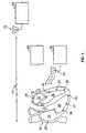
- FIG. 1is a conceptual diagram of a leadless cardiac stimulation system (with leadless, or wireless, electrode assemblies shown implanted in a heart) and of an external programmer.
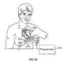
- FIGS. 2A and 2Bare exemplary systems of the type shown in FIG. 1 , and shown implanted in a body.
- FIG. 3is a block diagram of an exemplary embodiment of a combined controller/transmitter device and associated antenna that may be used as part of the FIG. 2A or 2 B system.
- FIG. 4is a schematic diagram of a portion of the circuitry included in a wireless electrode assembly as is shown in FIGS. 1 and 2 A-B.
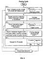
- FIG. 5is a flow chart of a method of providing stimulation pulses in a pacing cycle in a system such as shown in FIGS. 1 and 2 A-B.
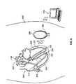
- FIG. 6is a diagram of the system shown in FIG. 2A and of an example wireless electrode assembly delivery catheter.
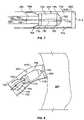
- FIG. 7is a side-view diagram of the delivery catheter shown in FIG. 6 , with portions removed to show a wireless electrode assembly and additional assemblies inside the catheter.
- FIG. 8is a diagram similar to FIG. 7 , with a distal end of the delivery catheter pressed against a myocardial wall.
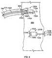
- FIG. 9is a diagram illustrating the delivery of a wireless electrode assembly from the delivery catheter and into the myocardial wall.
- FIG. 10is a flow chart of a method for delivering and implanting wireless electrode assemblies.
- FIGS. 11A-Dare diagrams of alternative embodiments of wireless electrode assemblies and associated delivery catheters, with the wireless electrode assemblies shown being implanted within a myocardial wall.
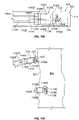
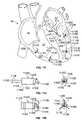
- FIGS. 11E-Ware diagrams of alternative embodiments of wireless electrode assemblies and associated delivery catheters.
- FIG. 12is a diagram of a wireless electrode assembly and associated delivery catheter, with the wireless electrode assembly shown implanted within a myocardial wall in a position such that its longitudinal axis is parallel with the myocardial wall.
- FIG. 13is a diagram of a wireless electrode assembly and an another embodiment of an associated delivery catheter.
- FIGS. 14A and 14Bare diagrams of an alternative embodiment of a wireless electrode assembly and associated delivery catheter, with the wireless electrode assembly being shown being implanted within a myocardial wall.
- FIG. 15is a diagram of an alternative embodiment of a coil for a wireless electrode assembly in which three orthogonal coils are wound on a single substrate.
- FIG. 16is a part schematic and part block diagram of a circuit that may be included within embodiments of wireless electrode assemblies to enable them to receive and to transmit information.
- FIG. 17is an example of a prior art, three-lead pacing system, showing one lead placed in a vein over the left ventricle.
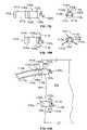
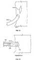
- FIGS. 18A to 18Cshow views of a wireless electrode assembly and a wireless electrode assembly attached to a tissue equivalent circuit.
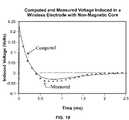
- FIG. 19is a graph of voltage, both computed and measured, induced in a wireless electrode assembly versus time.
- FIG. 20is a graph of voltage induced in a particular wireless electrode assembly versus time, with and without a tissue equivalent circuit attached across the electrodes.
- This documentdescribes various configurations of systems that employ leadless electrodes to provide pacing therapy or other tissue excitation and that are commercially practicable.
- One of the findings of the inventorsis that a significant issue to be considered in achieving a commercially practicable system is the overall energy efficiency of the implanted system. For example, the energy transfer efficiency of two inductively coupled coils decreases dramatically as the distance between the coils increases. Thus, for example, a transmitter coil implanted in the usual upper pectoral region may only be able to couple negligible energy to a small seed electrode coil located within the heart.
- FIG. 1shows a general depiction of such a system 10 and an external programming device 70 .
- the system 10includes a number of wireless electrode assemblies 20 , herein referred to simply as “seeds.”
- the seeds 20are implanted within chambers of the heart 30 .
- there are eight seeds 20there being one implanted in the left atrium 32 , three implanted in the left ventricle 34 , one implanted in the right atrium 36 , and three implanted in the right ventricle 38 .
- each of the seeds 20has an internal coil that is inductively coupled with an external power source coil to charge an electrical charge storage device contained within the seed 20 , and also has a triggering mechanism to deliver stored electrical charge to adjacent heart tissue.
- each seedhas no energy storage device such as a battery or capacitor.
- each seedmay be comprised, for example, of a ferrite core having caps at each end with ring electrodes encircling the caps, so as to form a dumbbell-shaped configuration.
- a number of turns of fine insulated wiremay be wrapped around the central portion of the core so as to receive energy from a magnetic field produced by a shaped driving signal and designed to activate the electrodes.
- FIGS. 18A to 18CSuch a configuration is discussed below in greater detail with reference to FIGS. 18A to 18C .
- the system 10also includes a pacing controller 40 and a transmitter 50 that drives an antenna 60 for communication with the seeds 20 .
- the pacing controller 40includes circuitry to sense and analyze the heart's electrical activity, and to determine if and when a pacing electrical pulse needs to be delivered and by which of the seeds 20 .
- the sensing capabilitymay be made possible by having sense electrodes included within the physical assembly of the pacing controller 40 .
- a conventional single or dual lead pacemaker(not shown in FIG. 1 ; although see FIG. 2B ) may sense the local cardiac electrocardiogram (ECG) and transmit this information to antenna 60 for use by controller 40 in determination of the timing of seed firing.
- ECGlocal cardiac electrocardiogram
- the seed 20need not be provided with sensing capability, and also the seeds 20 need not be equipped with the capability of communicating to the pacing controller 40 (for example, to communicate information about sensed electrical events).
- the seedsmay communicate sensed information to each other and/or to the controller 40 .
- the transmitter 50which is in communication with, and is controlled by, the pacing controller 40 —drives an RF signal onto the antenna 60 .
- the transmitter 50provides both 1) a charging signal to charge the electrical charge storage devices contained within the seeds 20 by inductive coupling, and 2) an information signal, such as a pacing trigger signal, that is communicated to a selected one or more of the seeds 20 , commanding that seed to deliver its stored charge to the adjacent tissue.
- An important parameter of the seed 20 that is a driver of the system 10 designis the maximum energy required to pace the ventricle.
- This energy requirementcan include a typical value needed to pace ventricular myocardium, but also can include a margin to account for degradation of contact between the electrodes and tissue over time. It is assumed that each seed may require the maximum pacing threshold energy.
- This threshold energyis supplied to the seeds between heartbeats by an external radio frequency generator (which may also be implanted), or other suitable energy source that may be implanted within the body. Typical values are:
- Threshold pacing voltage2.5 Volts
- Derived threshold energy4 micro-Joules Because RF fields at frequencies higher than about 100 kHz are attenuated by the body's electrical conductivity, and because electric fields of any frequency are attenuated within the body, energy transmission through the body may be accomplished via a magnetic field at about 20-100 kHz (or by a magnetic field pulse that contains major frequency components in this range), and preferably by transmission of magnetic fields in the range of 20-30 kHz when transmission is through relatively conductive blood and heart muscle.
- the pacing controller 40 and the transmitter 50may be housed in a single enclosure that is body implantable within a patient.
- the single enclosure devicemay have a single energy source (battery) that may be either rechargeable or non-rechargeable.
- the pacing controller 40 and the transmitter 50may be physically separate components.
- the pacing controller 50may be implantable, for example in the conventional pacemaker configuration, whereas the transmitter 50 (along with the antenna 60 ) may be adapted to be worn externally, such as in a harness that is worn by the patient.
- the pacing controller 40would have its own energy source (battery), and that energy would not be rechargeable given the relatively small energy requirements of the pacing controller 40 as compared to the energy requirements of the transmitter 50 to be able to electrically charge the seeds 20 .
- the pacing controller 40would sense the local cardiac ECG signal through a conventional pacing lead, and transmit the sensed information to the external controller. Again, transmission of information, as opposed to pacing energy, has a relatively low power requirement, so a conventional pacemaker enclosure and battery would suffice.
- the external programmer 70is used to communicate with the pacing controller 40 , including after the pacing controller 40 has been implanted.
- the external programmer 70may be used to program such parameters as the timing of stimulation pulses in relation to certain sensed electrical activity of the heart, the energy level of stimulation pulses, the duration of stimulation pulse (that is, pulse width), etc.
- the programmer 70includes an antenna 75 to communicate with the pacing controller 40 , using, for example, RF signals.
- the implantable pacing controller 40is accordingly equipped to communicate with the external programmer 70 , using, for example, RF signals.
- the antenna 60may be used to provide such communications, or alternatively, the pacing controller 40 may have an additional antenna (not shown in FIG. 1 ) for external communications with the programmer 70 , and in an embodiment where the transmitter 50 and antenna 60 are housed separately from the controller 40 , for communications with the transmitter 50 .
- FIG. 2Ashows an example system 200 of the type shown in FIG. 1 .
- the system 200is shown as having been implanted in a patient, and in addition, a programmer 270 is also shown that is external to the patient. As shown, the system 200 is of a type that is entirely implantable.
- the system 200includes several seed electrode assemblies 220 , there being four such assemblies shown as having been implanted within the heart 230 in FIG. 2A .
- the system 200also includes an implantable combined pacing controller and transmitter device 240 that has an antenna 260 for communicating, for example, to the seeds 220 .
- the controller/transmitter device 240is shaped generally elongate and slightly curved so that it may be anchored between two ribs of the patient, or possibly around two or more ribs.
- the controller/transmitter device 240is 2 to 20 cm long and 1 to 10 centimeters (cm) in diameter, preferably 5 to 10 cm long and 3 to 6 cm in diameter.
- Such a shape of the controller/transmitter device 240which allows the device 240 to be anchored on the ribs, allows an enclosure that is larger and heavier than conventional pacemakers, and allows a larger battery having more stored energy.
- Other sizes and configurationsmay also be employed as is practical.
- the antenna 260 in the FIG. 2A exampleis a loop antenna comprised of a long wire whose two ends 270 and 272 extend out of the housing of the controller/transmitter device 240 at one end 280 of the controller/transmitter device 240 .
- the opposite ends 270 and 272 of the loop antenna 260are electrically connected across an electronic circuit contained within the controller/transmitter device 240 , which circuit delivers pulses of RF current to the antenna, generating a magnetic field in the space around the antenna to charge the seeds, as well as RF control magnetic field signals to command the seeds to discharge.
- the loop antenna 260may be made of a flexible conductive material so that it may be manipulated by a physician during implantation into a configuration that achieves improved inductive coupling between the antenna 260 and the coils within the implanted seeds 220 .
- the loop antenna 260may be 2 to 22 cm long, and 1 to 11 cm wide, preferably 5 to 11 cm long, and 3 to 7 cm wide. Placement of the antenna over the ribs allows a relatively large antenna to be constructed that has improved efficiency in coupling RF energy to the pacing seeds.
- the loop antenna 260has been configured to extend generally around the periphery of the housing of the controller/transmitter device 240 .
- the loop antenna 260extends from its first end 270 (located at the first end 280 of the controller/transmitter device 240 ) outwardly and then generally parallel to the elongately shaped controller/transmitter device 240 to the second end 282 of the controller/transmitter device 240 .
- the loop antenna 260extends outwardly and again generally parallel to the controller/transmitter device 240 , albeit on an opposite side of the transmitter/controller device 240 , and back to the first end 280 of the controller/transmitter device 240 .
- the loop antenna 260may, like the controller/transmitter device 240 , be anchored to the ribs of the patient.
- the distance between the center of the loop antenna 260 and the seed electrode assemblies 220will typically be, on average, about three inches (3′′). As will be shown later, such a distance puts significant power demands on the controller/transmitter device 240 , and so an internal battery included within the controller/transmitter device 240 may need to be rechargeable. In some embodiments, however, the controller/transmitter device 240 may be non-rechargeable.
- the loop antenna 260may have a shape that is more complex than that shown in FIG. 2 , with a larger antenna area, or multiple antenna lobes to capture more tissue volume.
- the antennamay consist of two or more wire loops, for example, one on the front of the patient's rib cage, and a second on the back, to gain magnetic field access to a larger tissue region.
- FIG. 2Bthere is shown an embodiment as shown in FIG. 2A , but which also includes a conventional pacemaker, or pulse generator, 290 and associated wired leads 295 which extend from the pulse generator 290 and into chambers of the heart 600 .
- the pulse generator 290may be used to sense the internal ECG, and may also communicate with the controller/transmitter 240 as discussed previously.
- a battery 302which may be recharged by receiving RF energy from a source outside the body via antenna 260 ; ECG sensing electrodes 304 and associated sensing circuitry 306 ; circuitry 308 for transmitting firing commands to the implanted seeds, transmitting status information to the external programmer, receiving control instructions from the external programmer and receiving power to recharge the battery; and a controller or computer 310 that is programmed to control the overall functioning of the pacing control implant.
- antenna 260may receive signals from the individual seeds 220 containing information regarding the local ECG at the site of each seed, and/or antenna 260 may receive signals from a more conventional implanted pacemaker regarding the ECG signal at the sites of one or more conventional leads implanted on the right side of the heart.
- FIG. 4is a schematic diagram of an exemplary wireless electrode assembly, or seed, 420 that may serve as the seeds 20 or 220 as shown in either FIG. 1 or FIGS. 2A-B .
- the seed 420includes, firstly, a receiver coil 410 that is capable of being inductively coupled to a magnetic field source generating a time-varying magnetic field at the location of coil 410 , such as would be generated by the transmitter 50 and the antenna 60 shown in FIG. 1 .
- the RF current in the external antennamay be a pulsed alternating current (AC) or a pulsed DC current, and thus the current induced through the receiver coil 410 would likewise be an AC or pulsed DC current.
- ACpulsed alternating current
- DCpulsed DC current
- the current induced in coil 410is proportional to the time rate of change of the magnetic field generated at the site of coil 410 by the external RF current source.
- a four-diode bridge rectifier 415is connected across the receiver coil 410 to rectify the AC or pulsed DC current that is induced in the receiver coil 410 .
- a three-position switch device 418is connected so that when the switch device 418 is in a first position, the rectifier 415 produces a rectified output that is imposed across a capacitor 405 . As such, when the switch device 418 is in the position 1 (as is the case in FIG. 4 ), the capacitor 405 stores the induced electrical energy.
- the switch device 418in this example, is a voltage-controlled device and is connected to sense a voltage across the capacitor 405 to determine when the capacitor 405 has been sufficiently charged to a specified pacing threshold voltage level. When the capacitor 405 is sensed to have reached the specified pacing threshold level, the voltage-controlled switch device 418 moves to a position 2 , which disconnects the capacitor 405 from the coil 510 . With the switch device 418 in the position 2 , the capacitor 405 is electrically isolated and remains charged, and thus is ready to be discharged.
- the voltage controlled switch device 418may consist of a solid state switch, such as a field effect transistor, with its gate connected to the output of a voltage comparator that compares the voltage on capacitor 405 to a reference voltage.
- the reference voltagemay be set at the factory, or adjusted remotely after implant via signals sent from the physician programmer unit, received by coil 410 and processed by circuitry not shown in FIG. 4 .
- Any electronic circuitry contained within the seed, including the voltage controlled switch,is constructed with components that consume very little power, for example CMOS. Power for such circuitry is either taken from a micro-battery contained within the seed, or supplied by draining a small amount of charge from capacitor 405 .
- a narrow band pass filter device 425is also connected across the receiver coil 410 , as well as being connected to the three-position switch device 418 .
- the band pass filter device 425passes only a single frequency of communication signal that is induced in the coil 410 .
- the single frequency of the communication signal that is passed by the filter device 425is unique for the particular seed 20 as compared to other implanted seeds.
- the filter device 425passes the voltage to the switch device 418 , which in turn moves to a position 3 .
- the capacitor 405With the switch device in the position 3 , the capacitor 405 is connected in series through two bipolar electrodes 430 and 435 , to the tissue to be stimulated. As such, at least some of the charge that is stored on the capacitor 405 is discharged through the tissue. When this happens, the tissue becomes electrically depolarized.
- the bipolar electrodes 430 and 435 across which stimulation pulses are providedare physically located at opposite ends of the seed 420 . After a predetermined, or programmed, period of time, the switch returns to position 1 so the capacitor 405 may be charged back up to the selected threshold level.
- FIG. 4shows only the seed electrical components for energy storage and switching. Not shown are electronics to condition the pacing pulse delivered to the tissues, which circuitry would be known to persons skilled in the art.
- Some aspects of the pulsemay be remotely programmable via encoded signals received through the filter device 425 of the seed 420 .
- filter 425may be a simple band pass filter with a frequency unique to a particular seed, and the incoming signal may be modulated with programming information.
- filter 425may consist of any type of demodulator or decoder that receives analog or digital information induced by the external source in coil 410 .
- the received informationmay contain a code unique to each seed to command discharge of capacitor 405 , along with more elaborate instructions controlling discharge parameters such as threshold voltage for firing, duration and shape of the discharge pulse, etc.
- all of the implanted seedsmay be charged simultaneously by a single burst of an RF charging field from a transmitter antenna 60 .
- transmitter 50FIG. 1
- transmitter 50FIG. 1
- lossesare primarily due to Ohmic heating of the transmit antenna 60 during the transmit burst, Ohmic heating of the receive coil 410 , and Ohmic heating of conductive body tissues by eddy currents induced in these tissues by the applied RF magnetic field.
- the transmitter 50would be turned ON eight times as long, requiring almost eight times more transmit energy, the additional energy being primarily lost in heating of the transmit antenna 60 and conductive body tissues.
- FIG. 5is a flowchart of a pacing cycle that shows such a mode of operation of charging all implanted seeds 20 simultaneously, and triggering the discharge of each seed 20 independently.
- the methodstarts at step 510 with the start of a charging pulse that charges all of the seeds simultaneously.
- a pacing threshold voltageis attained or exceeded, at step 520 , the seeds switch to a standby mode (for example, switch 418 in seed 420 moves to position 2 ).
- a controller/transmitter devicesuch as device 240 shown in FIG.
- step 540that seed, namely seed 1 , receives the trigger pulse through the band pass filter, which in turn trips the switch to pace the tissue.
- This processmay be repeated for each of the N number of seeds that have been implanted, as indicated at step 550 , which returns to step 530 where there are additional seeds that have been charged and are to be fired.
- step 560there is a delay until the next diastole, after which time the process begins anew at step 510 .
- the exact time of firing of the first seedmay be programmed by the physician in relation to the ECG signal features measured by the sensing electrodes 304 in FIG. 3 , or in relation to ECG information transmitted to the controller 240 by the pacing seeds themselves, or in relation to pacing information transmitted to the controller 240 by a conventional implanted pacemaker, or in relation to pacing information received from a conventional implanted pacemaker through an implanted hard wire connection to controller 240 .
- Subsequent timing of the firing of each additional seedmay be programmed by the physician at the time of implant.
- seedsmay be programmed not to discharge. For example, an array of seeds may be implanted, but only a subset may be programmed to receive firing commands from the controller 240 .
- the controller/transmitter device 240 and associated antenna 260would first be implanted subcutaneously in a designed location (for example, between the ribs in the case of the FIG. 2A embodiment). The physician then may program the controller/transmitter 240 by delivering telemetric signals through the skin using the programmer 270 in a conventional manner, although this programming may also be done, at least in part, before implantation.
- One of the adjustable parametersis the timing of firing of each seed 220 , determined by a time at which a short burst of current at the frequency for the particular seed 220 is delivered to the antenna 260 .
- the controller/transmitter device 240may have a pair of sensing electrodes on its surface to detect the subcutaneous electrocardiogram (ECG), or it may contain multiple electrodes to provide a more detailed map of electrical activity from the heart.
- ECGsubcutaneous electrocardiogram
- This local ECG signal sensed by the controller/transmitter device 240may be used to trigger the onset of seed pacing when the patient has a functioning sinus node.
- the signals sensed by the controller/transmitter device 240are used to monitor ECG signals from the paced heart. In some cases, these ECG signals, or other physiologic sensor input signals, may be used to adjust or adapt the timing of firing of the pacing seeds 220 .
- the controller 240may receive local ECG or pacing information through an RF link from a conventional pacemaker 290 implanted in the pectoral region of the patient, as shown in FIG. 2B . This may be desirable in patients who already have a conventional pacemaker, or when local ECG data from the conventional atrial or right ventricular apex pacing sites are desired to coordinate the timing of firing of the implanted seeds 220 . Finally, the seeds 220 could themselves transmit information to controller 240 concerning the local bi-polar ECG measured at their sites.
- the seeds 220could sense the local ECG and discharge based upon this local data, with no firing instructions from the controller 240 required, or the seeds 220 could transmit information from seed 220 to seed concerning local ECG and onset of their discharge. All of the above embodiments, a combination, or a subset, may be implemented in this invention.
- the seeds 220would be delivered to their respective sites in the cardiac veins, within the heart wall, or on the epicardial surface of the heart via a catheter, as will be described in more detail later.
- a distal portion, or tip of the cathetermay contain a single electrode or a pair of electrodes, each being connected to a signal recorder via leads extending to a proximal end of the catheter.
- the physicianwould select the implantation site based upon features of the ECG signal sensed using the catheter.
- the seedthen may be injected through a needle extended from the catheter tip, or it may be pushed into the tissue and then released from the catheter. Many mechanisms may be used for seed release, including the release or addition of fluid pressure to the catheter tip.
- the seed 220may be charged and then fired to observe the altered electrogram proximate the seed at the location of the catheter tip.
- the physiciancan adjust the timing of seed firing by programming the controller/transmitter device 240 .
- the catheteror a seed delivery mechanism residing within the catheter
- a new delivery mechanism containing the next pacing seedmay be inserted and navigated to the next pacing site. Because seeds can be fired in any order, or not fired at all, a physician may deliver the seeds in any order. When the heart is deemed to be beating in synchrony, no further seeds need be implanted.
- an array of seedsmay be delivered to the veins and/or heart wall, and the physician can program a subset of seeds to fire in a sequence that optimizes the pumping efficiency of the heart. Ejection fraction and cardiac output may be measured to determine pumping efficiency. On any given heartbeat, some or all of the seeds would fire.
- the controller 240may be programmed to sequentially fire seeds, or some seeds may fire simultaneously.
- FIGS. 6-10show an example of a mechanical design for a seed electrode assembly and an example seed delivery device and method.
- a system of the type shown in FIG. 2is shown where three seed electrode assemblies 220 have been implanted within tissue of the heart 600 , and in particular, within a myocardial wall 605 of the heart 600 .
- the controller/transmitter device 240is shown implanted beneath the skin 610 of the patient.
- the antenna 260extends from within the controller/transmitter device 240 at one end of the device 240 , and then extends around the periphery of the device 240 , as described previously.
- the external programming device 270is also shown, which is used to communicate with the implanted controller/ transmitter 240 .
- Distal portions of two seed delivery catheters 615are shown in FIG. 6 , each extending within a chamber of the heart 600 and to a site near where one of the seeds 220 is located.
- the delivery catheter 615enables placement of a seed 220 and the ability to sense the electrical activity at the distal tip of delivery catheter 615 through catheter tip electrode 625 , so that a physician can determine if the location is a good candidate location for implantation of seed 220 . If the location is a good candidate, the seed 220 may be partially inserted into the tissue as shown in FIG. 9 .
- the seed 220may be charged and then discharged into the tissue, while the physician observes electrograms, including the local electrogram arising from electrode 625 , and perhaps an electrogram from the distal seed electrode taken through the pull wire 735 A.
- the seed 220may be removed from that site and positioned elsewhere. If it is an appropriate location, then the seed 220 has an anchoring mechanism that can be activated to implant the seed 220 permanently within the tissue so that it retains its location.
- Each of the catheters 615is shown in FIG. 6 extending into the heart 600 through a heart entry vessel 620 such as the inferior vena cava (for right chamber entry) or aortic valve (for left chamber entry).
- a distal portion 625 of the delivery catheter 615includes a sensing electrode for sensing the electrical activity at a tissue site where the seed 220 may be implanted.
- FIG. 7shows one of many possible embodiments of a wireless electrode assembly, or seed, 220 .
- the seed 220is shown in FIG. 7 within a distal portion of the seed delivery catheter 615 .
- the seed 220has a main body 702 that, in this example, is bullet shaped and has two bipolar electrodes 705 and 710 .
- One of the electrodes, namely electrode 705is located at a distal tip of the bullet-shaped seed body 702
- the other electrode 710is located at a proximal end of the seed body 702 .
- the bullet shape of the seed body 702enables it to be extended into tissue such as the myocardial wall 605 , as will be illustrated in later figures.
- the “nose,” or distal tip, of the seed body 702may be more cone-shaped than the embodiment shown in FIG. 7 . While the distal and proximal electrodes 705 and 710 are shown on the seed itself, other locations are possible, including placing the distal and proximal electrodes 705 and 710 at the ends of the attachment tines to achieve the maximum separation between electrodes.
- the seed delivery catheter 615consists of an elongate tube with a main lumen 712 extending though its entire length.
- the catheter 615has an opening 713 at its distal end so that the seed 220 may be released from the delivery catheter 615 .
- the catheter 615also has the previously discussed electrode 625 , which as shown extends around the periphery of the distal opening 713 .
- An electrically conductive lead 716is attached to the electrode 625 and extends proximally through the entire length of catheter lumen 712 , or through the wall of the catheter, and outside the body (not shown in FIG. 7 ).
- the lead 716is made of an electrically conductive material, and thus provides the local electrocardiogram (ECG) appearing at the distal electrode 625 .
- ECGelectrocardiogram
- the main lumen 712 of the seed delivery catheter 615may have an internal diameter of about two-and-a-half millimeters, and the seed delivery catheter 615 may have an outside diameter that is slightly larger than that.
- the seed body 702may have a width of about two millimeters, and the length of the seed body 702 may be about five to ten millimeters, for example. This enables the seed 220 to be implanted entirely within a myocardial wall 605 , which may, for example, be about 20 millimeters thick in the left ventricle.
- the seed 220has a pair of forward-end tines 715 and 720 that each extend from a common junction point 725 .
- Each of the tines 715 and 720may be about three to eight millimeters in length, for example.
- the seed body 702also has a central bore 730 extending longitudinally through a center of the seed body 702 .
- FIG. 7which shows the seed 220 not yet implanted, one of the forward-end tines, namely tine 720 , extends proximally into the bore 730 , while the other forward-end tine 715 extends distally to enable it to pierce through tissue.
- the junction point 725 for the tines 715 and 720may be pushed forward of the seed 220 body, and when the constrained tine 720 clears the central bore 730 , the tines 720 and 715 are biased to snap into a lateral configuration that will be shown in a later figure.
- the junction point 725is physically larger than the diameter of the central bore 730 , and thus enables the seed 220 to be pulled in a proximal direction by pulling on extraction wire 735 .
- the seed extraction wire 735is attached to the junction point 725 , and extends proximally through the entire length of the seed central bore 730 , and from there continues proximally through the delivery catheter 615 and outside the body (not shown in FIG. 7 ).
- the wire 735may be made of an electrically conductive material so as to sense an electrical signal appearing at a distal end of the wire 735 , thus serving as an extraction pull wire and as a temporary ECG lead for distal electrode 705 . This is a means of sensing a bipolar electrocardiogram at a proposed implantation site before permanently implanting the seed 220 , using electrode 705 (with wire lead 735 ) as a first electrode, and using the catheter electrode 625 and lead 716 as a second electrode.
- the extraction wire 735extends outside the patient's body, a physician may pull the wire 735 , and given that the junction point 725 is too large to be pulled into the seed body central bore 730 , pulling the wire 735 pulls the seed 220 proximally within the delivery catheter 615 .
- the extraction wire 735is also constructed of a material and of a diameter such that the wire 735 is rigid enough to be pushed forward to extend the junction point 725 forward of the seed 220 body and hence free the forward-end tine 720 from the constraining central bore 730 .
- the wire 735has stopper device 740 that is attached to the wire 735 at a point that is proximal of the seed 220 body.
- the stopper device 740like the junction point 725 , is larger than the seed body central bore 730 , and thus constrains how far the lead junction point 725 can be extended forward of the seed body 702 .
- the stopper device 740is positioned on the wire 735 at a location that is far enough away from the rear-end of the seed body 702 such that wire 735 may be pushed distally far enough to free the constrained tine 720 from the seed body central bore 730 .
- the extraction wire 735has a detachment mechanism 745 located on the wire 735 at a point that is immediately distal of the stopper device 740 .
- the detachment mechanism 745may be activated by a physician to detach the portion of wire 735 that is proximal of the detachment mechanism 745 .
- Various detachment mechanismsmay be used for the detachment mechanism 745 .
- the detachment mechanism 745may be a high-resistance portion of a conductive line that extends proximally to a point external of the patient, and that can be heated and detached by injecting current of a specified amount into the conductive line.
- the wire 735may serve three purposes: extraction of a seed 220 from a location that does not provide optimal cardiac resynchronization; conduction of the tip electrode 705 ECG signal to a recorder outside the body; conduction of a burst of current to detach itself at a point 745 of relatively high electrical resistance.
- the detachment mechanism 745is a mechanical configuration where the proximal detachable portion of the lead 735 may be unscrewed from the remainder of the lead 735 , or where the lead 735 is pushed and turned in a certain way to effect detachment of the proximal portion from the remainder of the lead 735 .
- a mechanical skiving or shearing meansmay alternatively be applied at point 745 .
- the seed 220also has a pair of tines 750 and 755 that extend from the rear end of the seed body 702 .
- there are two such tines 750 and 755though it will be understood that there may be more than two tines, or a single tine.
- the tines 750 and 755assist in securing the seed 220 at a desired location within the tissue, such as within a desired location of the myocardial wall 605 , to prevent the seed from migrating under the repeated stress of heart muscle contraction.
- the tines 750 and 755are attached to the rear-end electrode 710 near a periphery of the electrode 710 , and extend from their attachment points in a direction that is about 45 degrees from a longitudinal axis of the seed body 702 . As shown in FIG. 7 , however, far ends of the tines 750 and 755 are constrained by an outer wall of the catheter lumen 712 , and become bent toward the longitudinal axis of the catheter 615 . When the seed 220 is pushed out of the distal end of catheter 615 , the tines 750 and 755 spring outwardly into their normal position (not shown in FIG. 7 ).
- a tube 760 that is movable longitudinally within the catheter 615is used to push the seed 220 distally within the catheter 615 and out of the catheter distal opening 713 .
- the tubehas a lumen 765 extending longitudinally through its entire length so that the wire 735 extends through the tube lumen 765 .
- the cross-sectional diameter of the pusher tube 760may be, for example, about half that of the catheter lumen 712 . As such, where the catheter lumen 712 diameter is about 2.5 mm, the tube cross-sectional diameter may be about 1.25 mm.
- the seed delivery catheter 615with a seed 220 contained within, is shown with its circular distal electrode 625 pressed against the myocardial wall 605 .
- the electrical activity occurring at that site of the myocardial wall 605is monitored at a proximal end of the lead 716 to determine if the site is an appropriate candidate site in which to implant the seed 220 .
- the first seed 220 Ais shown during the process of implanting the seed 220 A within the myocardial wall 605 , with the assistance of the seed delivery catheter 615 .
- the second seed 220 Bis shown as having already been permanently implanted within the myocardial wall 605 .
- the first seed 220 Ais shown as having been pushed nearly entirely within the myocardial wall 605 . This was accomplished by the physician pushing the push tube 760 within the seed delivery catheter 615 so as to push the seed 220 A out of the catheter's distal opening 713 .
- the forwardly extending distal tine 715served to pierce the myocardial wall 615 and permit implantation within the wall 615 .
- the seed's rear-end tines 750 A and 755 Aare still partially within the seed delivery catheter 615 and thus are still being constrained from extending outwardly from the seed body's longitudinal axis. As such, it is still possible for the physician to pull back the seed 220 A from this position by pulling on the seed extraction wire 735 A. If the seed 220 A were to have been pushed a little further so that the proximal tines 750 A and 755 A become extended, then it may not be possible to pull back the seed 220 A. As discussed previously, seed 220 A may be charged and commanded to discharge while wire 735 serves as a lead to monitor the electrical activity at the forward end of the seed 220 A. The physician may determine that the present positioning is not appropriate, and wire 735 may then be pulled to extract the seed, which may then be moved to an alternate location.
- the wire 735has not yet been pushed forward to deploy the distal tines 715 A and 720 A ( 750 A not shown in FIG. 9 ).
- Deploying the distal tines 715 A and 720 Ais done as follows. First, the pushing tube 760 is used to push the seed 220 A so that, firstly, the proximal tines 750 A and 755 A are freed from the delivery catheter 615 and thus extend outwardly, and secondly, the seed's distal tine junction point 725 A extends distally of the seed, and preferably entirely through the myocardial wall 605 .
- junction point 725 A and one of the forward-end tines 715are both positioned outside the myocardial wall 605 in FIG. 9 .
- the wire 735 Ais pushed distally until the lead stopper device 740 becomes flush with the proximal seed electrode 710 A.
- the constrained tine 720 Abecomes removed from the seed body central bore, thus allowing the two distal tines 715 A and 720 A to pop into the lateral position.
- Seed 220 Bis shown in the deployed position, the proximal tines 750 B and 755 B are shown extended, and the two distal tines 715 B and 720 B are outside the myocardial wall 605 and extend laterally from the junction point 725 B.
- a flowchartis shown that describes a method of delivering a seed 220 using the catheter 615 or another similar delivery device.
- the methodbegins at step 1010 with the percutaneous transluminal delivery of the catheter 615 to the heart chamber. This may be accomplished in the following manner. First, an introducer is used to provide entry into, for example, the femoral vein or artery (depending on where the seed 220 is to be delivered). The catheter 615 is then inserted so that its distal end is snaked through the inferior vena cava and into the right atrium, for example. Thus, a seed 220 may be delivered in the right atrium.
- the distal end of the catheter 615may also be moved from the right atrium, through the tricuspid valve, and into the right ventricle, for delivery of a seed 220 there.
- the distal end of the cathetermay also be pushed through the fossa ovalis, accessed on the right atrial septum, for placement of seeds 220 in the left heart chambers.
- the distal end of the catheter 615may be snaked through the femoral artery and descending aorta, through the aortic valve and into the left ventricle, and from the left ventricle may be moved through the mitral valve into the left atrium. Navigating the catheter 615 may require that the catheter 615 have some type of navigational capability such as push and pull wires commonly used with electrophysiology catheters.
- a sample ECG signalmay be taken at sites on the heart inner wall. This may be done with the catheter 615 positioned as shown in FIG. 8 , for example.
- the physicianselects a site at which to deliver the seed 220 .
- the physiciandelivers the seed 220 into the myocardial wall tissue, such as shown with seed 220 A in FIG. 9 .
- the seed 220is still tethered by the lead 735 A so that the seed may be pulled back into the delivery catheter 615 if necessary.
- a test paceis performed to test the response at this site. This may be done using the programmer 270 shown in FIG. 6 to instruct the controller/transmitter device 240 to send a charging signal and then a trigger signal to the particular seed 220 .
- the seed 220may be removed and the process may be performed again starting at step 1020 . If, on the other hand, the pacing response is found to be acceptable, then, at step 1060 , the anchoring means for the seed 220 may be activated, for example, by moving the seed 220 entirely out of the catheter 615 and freeing the proximal tines 750 and 755 from the constraints of the catheter 615 and pushing the lead 735 to release the distal tines 715 and 720 . Also at step 1060 , the tether to the seed 220 may be released, for example, using the detachment mechanism 745 . Having completed the implantation of the seed, it is now possible at step 1070 to begin placement of the next seed 220 .
- each of the seeds 220may have a filter 425 (see FIG. 4 ) that allows passage of a signal of a particular frequency.
- each of the seeds 220may have a band pass filter 425 of a different center frequency.
- seeds 220may be manufactured as having one of sixteen different band pass frequencies.
- a code for the particular pass frequencymay be labeled directly on the seed 220 itself, or alternatively, may be labeled on the packaging for the seed 220 .
- the particular band pass frequency for each seed 220is communicated to the pacing controller 240 .
- FIG. 11Ashows a seed 11 20 A that is secured into the myocardium 605 with a distal spring 1105 A, or “cork screw.”
- a delivery rod 1110 provided by a delivery catheter 1112is detached from the seed 1120 A by turning the rod 1110 to engage the spring into tissue and also unscrew the threaded distal rod section 1115 from the seed 1120 A.
- a distal spring 1105 Bis screwed into the myocardium 605 using a clockwise rotation of the seed 1120 B, which also unscrews the delivery rod from the seed.
- proximal spring 1125Upon removal of the delivery rod, proximal spring 1125 is exposed to the myocardium 605 . Clockwise spring 1105 B and counter-clockwise spring 1125 together prevent rotation and translation of the seed through the myocardium. A mechanism for release of the springs is not shown in the figure. A small push rod passing through the delivery rod and seed could be used to push the distal spring from the seed and into a locked position. A thin sheath could cover proximal spring 1125 . The thin sheath would be retracted along with the delivery rod. Alternate means for detachment of the delivery rod include Ohmic heating of a high resistance portion of the rod, and mechanical shearing. In FIG.
- tines 1130are pushed, using a push rod 1135 provided through the main lumen of the delivery catheter 1112 , from the central portion of the seed 1120 C, out through channels 1140 and into the myocardium 605 , so that the tines 1130 extend laterally from the seed 1120 C body (as shown in FIG. 11D ), and so that the seed 1120 C becomes secured within the tissue.
- the push rod 1135is removable, at an attachment point, from a proximal end junction point 1145 of the tines 1130 .
- Various mechanisms for removing, or detaching the push rod 1135 from the tine proximal end junction point 1145may be employed, as discussed previously in connection with the FIG. 7 embodiment.
- some embodiments that are envisioned for seed delivery and detachmentinclude a seed 1120 E having a helical tine 1105 E and one or more adjustable tines 1110 E that secure the seed 1120 E to the myocardium 605 .
- detachment mechanisms 1145 E and 1165 Emay be used to release the seed 1120 E from an elongate shaft 1160 E after the seed 1120 E is secured to the myocardium 605 .
- the seed 1120 Eis shown within a distal portion of the seed delivery catheter 615 .
- the seed 1120 Ehas a main body 1122 E that, in this example, is cylindrically shaped with a tip portion 1123 E at a distal end.
- the seed 1120 Emay include two bipolar electrodes 1135 E and 1136 E that are capable of discharging an electrical pulse. Electrode 1135 E is located at the distal end of seed body 1122 E, and the other electrode 1136 E is located at a proximal end of the seed body 1122 E.
- the tip portion 1123 E of the seed body 1122 Ehas a modified cone shape that facilitates delivery of the distal end of the seed 1120 E into tissue such as the myocardial wall 605 , as will be illustrated in later figures.
- the tip portion 1123 Emay serve as a strain relief mechanism for the adjustable tines 1110 E that extend from the tip portion 1123 E.
- the tip portion 1123 Emay also deliver a steroid elution to minimize the formation of fibrous tissue at the seed/myocardium interface. While the distal and proximal electrodes 1135 E and 1136 E are shown on the seed body itself, other locations are possible.
- the distal electrode 1135 Emay be disposed at the end of the helical tine 1105 E to achieve the maximum separation between electrodes, or may be an entire tine.
- the surface of tip portion 1123 E on the seed body 1122 Emay function as the distal electrode 1135 E, which may provide a more efficient use of space when the seed body 1122 E is substantially smaller in size.
- using the surface of tip portion 1123 E to function as the distal electrode 1135 Emay be desirable in circumstances where only the tip portion 1123 E contacts the endocardium or myocardium tissue (described in more detail below).
- the seed delivery catheter 615includes an elongate tube with a main lumen 712 extending though its entire length.
- the catheter 615has an opening 713 at its distal end so that the seed 1120 E may be released from the distal end of the delivery catheter 615 .
- all or a portion of the seed 1120 Emay extend from the delivery catheter 615 before the seed 1120 E is secured to the heart tissue.
- the main lumen 712may still be sized to slidably engage the elongate shaft.
- the catheter 615may also have an electrically conductive lead 716 and an electrode 625 that extends around the periphery of the distal opening 713 and is capable of providing local ECG information as previously described.
- the distal end of the catheter 615may include a screw mechanism to temporarily secure the catheter 615 to the heart tissue (described in more detain below in connection with FIG. 13 ).
- the seed 1120 Ehas a plurality of adjustable tines 1110 E that each extend from a common junction member 1112 E. As shown in FIG. 11E , each of the adjustable tines 1110 E generally extend from the junction member 1112 E through a central bore 1130 E of the seed body 1122 E. FIG. 11E shows the seed 1120 E not yet implanted, and only the helical tine 1105 E extends from the seed body 1122 E while the adjustable tines 1110 E are disposed in the central bore 1130 E. As will be described in more detail later, the junction member 1112 E may be pushed in a distal direction by an actuation rod 1170 E, thereby forcing the adjustable tines 1110 E from the distal end of the central bore 1130 E.
- the tines 1110 EWhen the constrained tines 1110 E extend from the central bore 1130 E, the tines 1110 E are biased to extend in a curled or hook configuration.
- the junction member 1112 Emay be physically larger than the diameter of the central bore 1130 E, providing a stopping point for actuation of the adjustable tines 1110 E.
- the elongate shaft 1160 Eincludes a detachment mechanism 1165 E at a distal end that is capable of engaging/disengaging the detachment mechanism 1145 E of the seed 1120 E.
- the detachment mechanism 1165 Eincludes a threaded member that engages a complementary threaded member on the seed's detachment mechanism 1145 E.
- the threaded engagement between the detachment mechanisms 1165 E and 1145 Emay be arranged so that the threads would not release when the seed 1120 E is being advanced into the tissue with the rotation of the helical tine 1105 E.
- the elongate shaft 1160 Econtinues proximally through the delivery catheter 615 and outside the patient's body (not shown in FIG. 11E ).
- a physicianmay direct the seed body 1122 E (via the elongate shaft 1160 E coupled thereto) through the lumen 712 of the delivery catheter 615 .
- the delivery catheter 615may be navigated through an access catheter or other steerable sheath to the implantation site.
- the access catheteris capable of maintaining a stable valve crossing, which can reduce trauma to the valve and facilitate the implantation of multiple seeds into the wall of the heart chamber.
- the elongate shaft 1160 Emay be constructed of a material and of a size and design such that the elongate shaft 1160 E is sufficiently rigid to be rotated within the main lumen for purposes of engaging the helical tine 1105 E with the myocardium tissue. Also, the elongate shaft 1160 E may be sufficiently flexible so as to not impede navigation of the elongate shaft 1160 E and the catheter 615 to the implantation site.
- the actuation rod 1170 Emay be disposed in a lumen 1162 E of the elongate shaft 1160 E.
- the actuation rod 1170 Eincludes an engagement surface 1172 E that is adapted to contact the junction member 1112 E. From the engagement surface 1172 E, the actuation rod 1170 E may continue proximally through the elongate shaft 1160 E and outside the patient's body. In such embodiments, a physician may apply a force at the proximal end of the actuation rod 1170 E so as to slide the rod 1170 E within the elongate shaft 1160 E. Such motion of the elongate rod 1170 E may apply a distal force upon the junction member 1112 E.
- the actuation rod 1170 Emay be constructed of a material and be of a size such that the actuation rod is sufficiently rigid to push against the junction member 1112 E and force adjustable tines 1110 E to extend from the distal end of the central bore 1130 E. Also, the elongate rod 1170 E may be sufficiently flexible so as to be guided through the lumen 1162 E of the elongate shaft 1160 E.
- FIGS. 11F-11Hat least a portion of the seed 1120 E shown in FIG. 11E may be implanted into myocardium 605 .
- the delivery catheter 615may be guided into a heart chamber (e.g., left atrium 32 , left ventricle 34 , right atrium 36 , or right ventricle 38 ) to enable placement of at least a portion of the seed 1120 E from the heart chamber into the myocardium 605 .
- the seedmay pass necessarily from the distal opening 713 of the catheter 615 , through an inner lining of the heart wall (e.g., the endocardium 606 ), and into the myocardium 605 .
- FIGS. 11F-11Hshow a seed 1120 E that is being implanted into the myocardium 605 and also show a neighboring seed 1120 E (below the first seed 1120 E) that was previously secured to the myocardium 605 .
- the seed 1120 E in the lumen 712 of the delivery catheter 615may be directed toward the distal end by a force 1167 E from the elongate shaft 1160 .
- the distal end of the delivery catheter 615may abut (or be positioned proximate to) the inner surface of the heart chamber so that the seed 1120 E is guided to a selected site of the heart wall.
- adjustable tines 1110 E of the seed 1120 E in the delivery catheter 615are not in an actuated position where they extend from the distal end of the central bore 1130 E (the adjustable tines 1110 E of the neighboring seed 1120 E that was previously implanted are shown in an actuated position).
- the helical tine 1105 Eis configured to penetrate through the endocardium 606 and into the myocardium 605 , as described in more detail below.
- the seed 1120 E in the lumen 712 of the delivery catheter 615may be rotated by a torsional force 1168 E from the elongate shaft 1160 .
- the helical tine 1105 Emay be “screwed” into the heart wall. In such circumstances, the helical tine 1105 E penetrates through the endocardium 606 and into the myocardium 605 .
- the detachment mechanism 1145 Eincludes a threaded member
- the torsion force 1168 E from the elongate shaft 1160 Emay serve to maintain or tighten the threaded engagement.
- the seed's adjustable tines 1110 Eare not extended from the central bore 1130 E (as shown by the neighboring seed). As such, it is still possible for the physician to pull back the seed 1110 E from this position by rotating the elongate shaft 1160 E in a direction opposite of force 1168 E, which would cause the helical tine 1105 E to “unscrew” from the myocardium tissue.
- the seed's distal electrode 1135 Eis in contact with the myocardium 605 .
- seed 1120 Emay be commanded to discharge a pacing electrical pulse while electrode 625 on the delivery catheter 615 monitors the electrical activity at the selected site.
- the seed 1120 Emay be retracted into the delivery catheter lumen 712 , which may then be moved to an alternate location. At the alternate location, the helical tine 1105 E would again penetrate through the endocardium and into the myocardium 605 , in which case further monitoring of electrical activity may occur.
- the adjustable tines 1110 Emay be forced to an actuated position.
- the actuation rod 1170 E disposed in the elongated shaft 1160 Eis capable of applying a force on the junction member 1112 E.
- the adjustable tines 1110 Eextend from the distal end of the central bore 1130 E.
- the adjustable tines 1110 Eare biased to have a curled or hook shape when unconstrained by the central bore 1130 E.
- the adjustable tines 1110 Emay comprise a shape memory alloy material, such as nitinol or the like, that is capable of returning to its biased shape after being elastically deformed within the central bore 1130 E.
- the adjustable tines 1110 Eembed in the myocardium 605 to provide supplemental anchoring support and to substantially hinder additional rotation of the seed body 1122 E.
- the elongate shaft 1160 Emay be rotated backward relative to the seed body 1122 E, which causes the threaded members of detachment mechanisms 1165 E and 1145 E to disengage one another.
- the elongate shaft 1160 Emay be rotated relative to the seed body 1122 E without extracting the seed 1120 E from the myocardium 605 because the adjustable tines 1110 E prevent the helical tine 1105 E from being “unscrewed.” After the seed 1120 E is detached from the elongate shaft 1160 E, the delivery catheter 615 and the elongate shaft 1160 E may be withdrawn from the implantation site.
- the adjustable tinesalso reduce the likelihood of the seed body 1122 E being pulled or torn from the heart wall.
- the seed 1120 Emay be exposed to various forces from the beating heart and the turbulence of the blood in the heart chambers.
- the seed 1120 Emay be attached to the heart wall so that a threshold amount of pull force is required to remove the seed 1120 E from the heart wall.
- Certain embodiments of seed 1120 Emay be secured to the heart wall such that a pull force of greater than 0.3 lbs. is required to remove the seed body 1122 E from the heart wall.
- the a seed 1120 Emay be secured to the heart wall such that a pull force of greater than 0.5 lbs., and preferably greater than 1.0 lbs., is required to remove the seed body 1122 E from the heart wall.
- Several seeds 1120 Ewere secured to the myocardium of a porcine (pig) heart using the helical tine 1105 E and three adjustable tines 1110 E.
- the porcine heartwas delivered to a lab where a portion of it was removed by scalpel to reveal an internal heart chamber.
- Several seeds 1120 Ewere secured to the porcine heart wall from the internal heart chamber—first by rotating the helical tine 1105 E into the myocardium and then by actuating the adjustable tines 1110 E to a curled shape substantially within the myocardium tissue.
- Each of the seeds 1120 Ewas secured to the heart wall such that a pull force of greater than 0.3 lbs. was required to remove the seed body 1122 E from the heart wall, and in some instances, a pull force of greater than 1.0 lbs. was required.
- helical tine 1105 E and the adjustable tines 1110 Emay secure the seed 1120 E to the myocardium 605 such that at least a portion of the seed body 1122 E (e.g., the tip portion 1123 E) penetrates into the myocardium 605 .
- the seed body 1122 Emay be fully inserted into the myocardium tissue.
- a distal portion of the seed body 1122 Eextends into the myocardium 605 while a proximal portion of the seed body 1122 E is exposed to the heart chamber (e.g., left atrium 32 , left ventricle 34 , right atrium 36 , or right ventricle 38 ).
- the seed body 1122 Emay be secured to the myocardium 605 so that the distal electrode 1135 E is in contact with the myocardium while the proximal electrode 1136 E is exposed to the heart chamber (and the blood therein). In certain cases, such positioning of the seed body 1122 E may be dictated by a limited thickness in the myocardium wall.
- the seed body 1122 Emay not fully penetrate into the myocardium 605 .
- a portion of the seed 1120 Ee.g., the helical tine 1105 E and the adjustable tines 1110 E
- the tip portion 1123 Emay contact or penetrate into the endocardium (and perhaps partially into the myocardium), but the other portions of the seed body 1122 E may not penetrate into the heart wall.
- the seed 1120 Emay be capable of providing a pacing electrical pulse to the proximal heart tissue.
- the delivery of the pacing electrical pulsemay be facilitated by using a surface of tip portion 1123 E to function as the distal electrode 1135 E.
- such positioning of the seed body 1122 Emay provide operational advantages. For example, if the distal electrode 1135 E is a cathode that generally depolarizes nearby tissue cells, and if the proximal electrode 1136 E is an anode that may hyper-polarize nearby tissue cells, the position of the seed body 1122 E shown in FIGS. 11F-11I may reduce the effects of hyper-polarization. Because, in this example, the anode is generally exposed to blood in the heart chamber, the tissue cells in the myocardium are not necessarily hyper-polarized by the anode.
- the pacing electrical charge between the cathode, the nearby myocardium, the nearby blood in the heart chamber, and the anodemay reduce the hyper-polarization of local areas in the myocardium tissue—a factor that may limit pacing effectiveness.
- a distal end 676 of an access catheter 675may be guided to a heart chamber where the seed 1120 E is to be delivered.
- the access catheter 675includes a lumen that extends from a proximal end to the distal end 676 .
- the access catheteralso includes a distal opening through which the delivery catheter 615 slidably passes as it is directed to the selected site proximal to the heart wall.
- the access catheter 675may be used to establish and maintain a valve crossing. In such circumstances, the delivery catheter 615 may be fully withdrawn from the patient's body after a first seed 1120 E has been successfully implanted, yet the access catheter 675 can maintain its position in the heart chamber.
- a new delivery catheter 615 and elongated shaft 1160 Emay be guided through the access catheter 675 are into the heart chamber.
- the access catheter 675may approach the left ventricle 34 through the aorta (e.g., across the aortic valve and into the left ventricle 34 ).
- Other approachesare contemplated, depending on the targeted heart chamber, the conditions in the patient's heart vessels, the entry point into the patient's body, and other factors.
- the access catheter 675may approach the left ventricle 34 through the inferior vena cava, through a puncture in the atrial septum, and down through the mitral valve into the left ventricle 34 .
- the delivery catheter 615may include a steering mechanism, such as push or pull wires, to aid in placement of the distal end of the catheter 615 against a selected site on the wall of the heart.
- the access catheter 675may include a steering mechanism, such as push or pull wires, to aid in placement of the distal end 676 in the selected heart chamber.
- the access catheter 675includes an image device 685 , such as an ultrasound probe or the like, proximal to the distal end 676 of the access catheter 675 .
- the image device 685is capable of providing the physician with visualization of the implantation site in the heart chamber.
- the image device 685can be used by a physician to visualize the implantation site and possibly measure the myocardium wall thickness at that site. Such a feature may be particularly advantageous where the procedure is to be conducted on an active, beating heart.
- the adjustable tines 1110 E of the seed 1120 Emay be forced from a non-actuated position (e.g., FIG. 11J ) to an actuated position (e.g., FIG. 11K ).
- the seed 1120 Emay include a plurality of adjustable tines 1110 E.
- the seed 1120 Eincludes three adjustable tines 1110 E that each extend from the common junction member 1112 E.
- the junction member 1112 Eis offset from the seed body 1122 E, and at least a portion of the adjustable tines 1110 E are constrained in the central bore 1130 E.
- each of the tines 1110 Emay be biased to extend in a curled or hooked shape after being released from the central bore 1130 E.
- alternate embodiments of the seedmay include adjustable tines that are not disposed in a central bore of the seed body.
- a seed 1120 Lmay include a plurality of adjustable tines 1110 L that are disposed in non-central bores 1130 L that extend in a longitudinal direction near the periphery of the seed body 1122 L.
- the adjustable tines 1110 L of the seed 1120 Lmay be forced from a non-actuated position (e.g., FIG. 11L ) to an actuated position (e.g., FIG. 11M ).
- the seed 1120 Lincludes a helical tine 1105 L that extends distally from the seed body 1122 L and includes three adjustable tines 1110 L that each extend from a common junction member 1112 L.
- the junction member 1112 Lis offset from the seed body 1122 L, and at least a portion of the adjustable tines 1110 L are constrained in the associated peripheral bores 1130 L.
- the junction member 1112 Lis forced in a generally distal direction toward the seed body 1122 L, as shown in FIG. 11K , the adjustable tines 1110 L are moved to an actuated position.
- each of the tines 1110 Lmay be biased to extend in a curled or hook shape after being released from its associated bore 1130 L.
- the tines 1110 Lmay also extend from the sides of seed 1120 L, such as through electrode 1135 L, and could also operate to extend excitation signals from electrode 1135 L into the tissue.
- this embodiment of the seed 1120 Lmay be directed to the targeted site of the heart wall using a delivery catheter 615 and an elongate shaft 1160 L.
- the elongated shaft 1160 Lmay include a detachment mechanism 1165 L that engages/disengages with the seed 1120 L.
- the detachment mechanism 1165 Lincludes a threaded member that engages a complementary threaded member of the seed's detachment mechanism 1145 L.
- the seed 1120 Lmay be rotated such that the helical tine 1105 L penetrates through the endocardium 606 and into the myocardium 605 .
- a force from an actuation rod 1170 Lmay move the junction member 1112 L in a distal direction toward the seed body 1122 L.
- Such motioncauses the adjustable tines 1110 L to extend from the distal ends of the peripheral bores 1130 L, thereby causing the adjustable tines 1110 L and the helical tine 1105 L to secure the seed 1120 L to the myocardium 605 .
- the elongate shaft 1160 Lmay be rotated to release the seed 1120 L at the detachment mechanisms 1145 L and 1165 L, which permits the delivery catheter 615 and the elongated shaft 1160 L to be withdrawn from the implantation site.
- a seed 1120 Pmay include a body screw 1106 P and adjustable tines 1110 P to secure the seed 1120 P to the myocardium 605 .
- the body screw 1106 Pmay include threads that are wound around the seed body 1122 P so that rotation of the seed body 1122 P causes that penetration through the endocardium 606 and into the myocardium 605 .
- the threadsmay be interrupted and twisted in some circumstances to help ensure that the seed 1120 P does not back out of the tissue.
- the adjustable tines 1110 Pmay be actuated when a junction member 1112 P is moved in a distal direction toward the seed body 1122 P.
- some embodiments of a seedmay include a single adjustable tine that helps to secure the seed to the myocardium 605 .
- the seed 1120 Qmay include a body screw 1106 Q and an adjustable tine 1110 Q that is actuated by moving a junction member 1112 Q toward the seed body 1122 Q.
- FIGS. 11P-11Qmay provide additional benefits to advancing the seed 1120 P into tissue.
- the seed 1120 Pmay create an opening for the passage of the seed body 1122 P more easily into the tissue.
- the distal portion of the helical tinecan pass into the heart wall tissue, but further progress may be blocked when the seed body 1122 P abuts the tissue. Also, while the thread is shown in FIGS.
- 11P-11Qas being disposed tight to the seed body 1122 P, it could also be separated slightly from the seed body 1122 P, particularly around the front tapered portion of the seed body 1122 P, and then connected back to the seed body 1122 P, for example, by a thin webbed section that can itself cut into the tissue. While it is not necessary for all embodiments that the seed body be placed into the tissue, other appropriate arrangements may be used that allow the seed body 1122 to enter into the tissue without significant disruption to the physical structure of the tissue.
- some embodiments of a seedmay include an adjustable barb that helps to secure the seed to the myocardium 605 .
- the adjustable barbmay include biased extensions that outwardly shift when no longer constrained in a bore.
- the seed 1120 Rmay include a body screw 1106 R that transitions into a helical tine 1105 R and an adjustable barb 1111 R that is actuated by moving a junction member 1112 R toward the seed body 1122 R.
- some embodiments of a seed 1120 Smay include a helical tine 1105 S and an adjustable barb 1111 S to secure the seed 1120 S to the myocardium 605 .
- the adjustable barb 1111 Smay be actuated by moving a junction member 1112 S toward the seed body 1122 S.
- some embodiments of a seedmay include one or more body barbs 1107 T that help to secure the seed to the myocardium 605 .
- the body barbs 1107 Tmay extend from the seed body 1122 T and acts as hooks that prevent the retraction from the myocardium 605 .
- the seed 1120 Tmay be fully embedded in the myocardium 605 and include body barbs 1107 T and adjustable tines 1110 T that can be actuated by moving a junction member 1112 T toward the seed body 1122 T. Referring to FIG.
- a seed 1120 Umay include body barbs 1107 U and an adjustable barb 1111 U to secure the seed 1120 U to the myocardium 605 .
- the adjustable barb 1111 Umay be actuated by moving a junction member 1112 U toward the seed body 1122 U.
- some embodiments of the detachment mechanism between the elongate shaft and the seedmay include a locking member that is movable between an engaged position (e.g., FIG. 11V ) and a disengaged position (e.g., FIG. 11W ).
- the elongate shaftmay have a noncircular outer cross-section (such as a square or hexagonal cross-sectional outer shape) to facilitate translation of rotational motion to the seed body.
- the seed 1120 Vmay include a body 1122 V and electrodes 1135 V and 1136 V, as described in previous embodiments. Furthermore, the seed 1120 V may include tines, screws, barbs, hooks, or other fasteners (such as a helical tine 1105 V, adjustable tines 1110 V that extend from a common junction member 1112 V) as previously described. Also as previously described, the seed 1120 V may be directed by an elongated shaft 1160 V through a lumen 712 of a delivery catheter 615 . The seed 1120 V may include a detachment mechanism 1145 V having a cavity 1146 V shaped to receive at least a portion of a locking member 1166 V.
- the cavity 1146 Vmay be curved to fit a spherically shaped locking member 1166 V like a small ball such that, when the locking member 1166 V is engaged with the cavity 1146 V, the elongate shaft 1160 V is not retractable from the seed body 1122 V.
- a force 1177 Vmay be applied from the actuation rod 1170 V may be to move the junction member 1112 V toward the seed body 1122 V.
- Such motion of the junction member 1112 Vmay cause the adjustable tines 1110 V to extend from the seed body 1122 V, thereby securing the seed 1120 V to the myocardium 605 .
- the motion of the actuation rod 1170 Vmay cause the locking member to move to a disengaged position.
- the actuation rod 1170 Vmay include a depressed surface 1176 V that is substantially aligned with the locking member 1166 V when the actuation rod 1170 V forces the junction member 1112 V to actuate the tines 1110 V.
- the locking member 1166 Vmoves toward the depressed surface 1176 V and disengages with the cavity 1146 V. This disengagement permits the actuation rod 1170 V, the elongate shaft 1160 V, and the delivery catheter 615 to be withdrawn from the seed implantation site while at least a portion of the seed 1120 V remains secured to the myocardium 605 .
- Detachment mechanisms other than those discussed abovemay also be used in appropriate situations.
- multiple spherically shaped locking members like that discussed abovemay be attached along the length of a wire, such as by soldering.
- the wiremay be passed down an interior passage of multiple seeds that are mounted end-to-end on the tip of a catheter.
- Each locking membermay be located so as to extend out of a central bore inside the seeds to lock against a corresponding cavity on an internal surface of a seed. In operation, and with locking member holding each seed in place, the most distal seed may be driven into the tissue by rotating the seeds.
- the wiremay then be withdrawn proximally the length of one seed, so that the locking member in the most distal seed is pulled back to the second-most-distal seed, and the other locking members move back one seed.
- a controlled withdrawal of the wiremay be accomplished, for example, using an indexed trigger mechanism that is handled by the surgeon.
- the seedsmay be provided with alternative mechanisms for removal, such as for use when the primary attachment mechanisms are damaged, occluded, or otherwise unavailable.
- several channelsmay be formed about the periphery of a proximal, nonimplanted electrode.
- the channelsmay proceed from shallow to deep so that, for example, a tool having radially-arranged fingers with inward extensions may position those extensions around the electrode.
- the fingerscan then be contracted, such as by a sleeve that is slid down around the exterior of the fingers, and the extensions may be received into the channels.
- the toolmay then be rotated so that the extensions move down into the deep portions of the channels and engage the seed in rotation so that the seed may be removed from the tissue.
- FIG. 12illustrates the possibility that seeds 1220 may be placed parallel to the heart wall 605 , in addition or in preference to transverse placement. This may be particularly necessary where the heart wall is thin, for example in the atria or in regions of the ventricles that contain scar tissue. Placement parallel to the wall is particularly required when the wall thickness is less than the seed length.
- the catheter 1212may be curved near its tip to facilitate parallel placement. Since the heart wall 605 is moving during the cardiac cycle, it may be necessary to secure the tip of the catheter 1212 to the heart tissue during seed placement. This concept is illustrated in FIG. 13 , showing a cork screw 1350 temporary securement of the catheter 1312 to the wall 605 . Tines that extend from the distal end of the catheter for penetration into the heart wall to secure and stabilize the catheter tip during seed delivery are also envisioned. The tines would be extended into the heart wall before seed placement, and retracted from the heart wall after seed placement.
- FIGS. 14A and 14Bshow a seed embodiment in which a seed pick-up coil 1460 also serves the function as a distal attachment, extending into the epicardial space 1465 .
- the seedincludes a seed body 1402 , the distally extending coil 1460 and proximal tines 1465 .
- the coil 1460is wrapped down in a delivery tube 1470 provided by a catheter 1412 , and expands to its full diameter after being pushed into the epicardial space 1465 .
- the seedis pushed using a push rod, or wire, 1475 that operates to push the coil 1460 from the distal opening in the delivery tube 1470 and into the epicardial space.
- the seed body 1402 and proximal tinesremain within the heart wall 605 .
- the expanded coil 1460has the advantage of collecting more magnetic flux by virtue of its larger diameter, leading to better coupling to the antenna, and a more efficient pacing system.
- the seed in FIGS. 14A-Bcan have a reduced diameter because it does not contain a relatively bulky coil.
- the seed body 1402contains the capacitor and electronic components indicated in the schematic of FIG. 4 . Proximal tines 1465 are shown attached to the seed for additional securement.
- tines 715 , 720 , 750 and 755may be plated with a suitable conductive material to serve as electrodes that extend into the epicardial space.
- the proximal tines 750 and 755could be plated with a conductive material and serve as an extension of proximal electrode 710 . Current passing between distal and proximal tines would encounter refractory tissues with a high degree of probability.
- the epicardial coil 1460 of FIG. 14may contain a central conducting coil surrounded by an electrical insulator, which is in turn coated with a conductive electrode material.
- FIG. 15shown in FIG. 15 is an alternative seed coil embodiment in which three orthogonal coils are wound on a single substrate.
- the substratemay be made from a permeable material. Currents induced in each of the three coils would be rectified, and passed to a single capacitor.
- the orientation of the seed relative to the transmit antennais immaterial. This is important because there is no coupling between a coil having its axis parallel to the plane of the antenna, and it may not always be possible to implant a seed with its axis perpendicular to the plane of the antenna.
- the seed of FIG. 15collects magnetic flux in each of three orthogonal directions, so that maximum flux is collected independent of the orientation of the incident magnetic field.
- the electrical parameters in the seed circuit of FIG. 4 , and the geometry of the antenna 260 of FIG. 6may be optimized by the use of a computer model for the response of the seed to the magnetic field generated by the antenna.
- the fundamental requirementis that the energy stored on capacitor 405 of FIG. 4 after charging is complete be equal to the pacing threshold energy for the tissue surrounding the seed.
- the total energy required to pace N sitesis then on the order of N times the threshold energy E 0 .
- the energy that must be supplied by the antenna 260 on each heartbeatis this minimum pacing energy times the overall efficiency of coupling energy from the antenna to seeds.
- the energy delivered to each seed in a charging time, ⁇may be computed for a given set of seed circuit parameters and a measured or computed magnetic field versus time at the site of the seed in question. This is possible because the voltage induced in coil 410 is known to be equal to the time rate of change of magnetic flux linking the coil.
- the steps needed to compute the energy stored on a given seed capacitorare:
- the magnetic fieldfalls off rapidly as the separation between the seed and the antenna increases. While this may not be true for very large antennas, the body dimensions limit the practical dimensions of the antenna.
- the exact location (and orientation if the seed does not have a tri-axial coil) of the seedwill determine the antenna current magnitude and ON-time required to charge that seed.
- the seed that links the least magnetic flux from the antennawill then determine these antenna parameters, since all seeds must be capable of acquiring the threshold energy for pacing. We may refer to this seed as the “weakest link”, and it alone will be used to compute optimal antenna current waveform and coupling efficiency.
- the energy coupling efficiencyis defined as the ratio of the total energy delivered to the seed capacitors, NE 0 , divided by the sum of all energy lost by the antenna during the on-time.
- Antenna losses that may be included in simulationsinclude:
- the energy coupling efficiencyis then given by NE 0 divided by the sum of losses listed above over the duration of the charging time.
- the Ohmic heat in the antenna circuitis primarily due to I 2 R losses in the antenna itself, and hysteresis losses in any magnetic materials that may be included in the antenna design. This statement is also true for Ohmic heating in the seed circuit.
- optimization of seed design, antenna design, and antenna circuit waveformis performed by iterating steps 1)-11) to maximize coupling efficiency.
- the lifetime of the transmitter batteryis readily computed from the energy coupling efficiency since on each heart beat the antenna must supply the total pacing energy, NE 0 divided by the coupling efficiency.
- the total energy contained in the batteryis its volume times its energy density.
- the total expected number of heartbeats that the system can paceis then the total battery energy times the energy coupling efficiency divided by the pacing energy per heartbeat, NE 0 .
- a seedcontained a coil 3 mm long by 2 mm diameter wound on a core with relative permeability equal to ten.
- the capacitancewas chosen to make the coil resonant at the frequency of the applied magnetic field.
- a further constraintwas made by choosing the Q of the coil (resonant frequency divided by the width of the resonance peak) equal to ten. This constraint of a modest Q provides a margin for possible frequency dispersion by conductive tissues, and a manufacturing margin. Given these assumptions it was found that a magnetic field directed along the axis of the coil must have a magnitude of about 0.001 Tesla (1 mT) to provide the minimum pacing energy of 4 ⁇ J.
- the antenna model in this calculationwas a five inch diameter circular loop of copper having a total weight of 100 grams.
- the tissue model employedwas a combination of heart muscle and blood, having about the same electrical conductivity.
- the optimal energy couplingoccurred at a frequency of about 30,000 Hz (30 kHz), where efficiency peaked at about 0.5%, and the lifetime of a 100 gram battery with 720 Joules/gram energy density was about 2 months.
- the efficiencycan be improved by improving magnetic coupling between the seeds and the antenna. This may be accomplished by using multiple antennas, for example one loop on the ribs over the anterior side of the heart, and one loop on the ribs over the posterior side of the heart. Two or more antenna loops may insure that the weakest link seed is closer to a loop than the three inches used in the example above.
- An alternative location for an antenna loopmay be a loop inserted into the right ventricle of the heart, and attached to a controller placed at the usual pectoral implant location. Such a loop would be located closer to all seeds, particularly since the antenna is energized during systole when the heart is contracted.
- Battery lifetimecan be extended indefinitely by employing a rechargeable battery.
- the batterymay receive energy for recharging by inductive coupling to antenna 260 .
- External antennae and transmitters for rechargingcould be located under or around the patient's bed or chair, or be integrated into special clothing.
- the antenna, transmitter, and battery of FIG. 3could be integrated into clothing or a disposable patch worn by the patient.
- ECG signals needed to time the seed pacingcould be received via an inductive link from a conventional pacemaker with right atrial and right ventricle leads.
- elaborate antenna designscould be incorporated into the special clothing.
- the antennacould have a portion that surrounds the chest at the latitude of the heart.
- FIG. 16shows a schematic diagram of an antenna 260 with the charging current waveform being supplied by capacitive discharge through the antenna 260 , and capacitor recharge provided by a battery 1605 .
- the value chosen for the capacitor 1610determines if the current waveform has a single peak or whether the current rings down in a damped sine waveform.
- Communications electronics 1615sends pacing discharge signals to the seeds, but may also receive ECG signals from the seeds or a conventional pacemaker.
- the charge electronics 1620receives energy via the antenna from an inductive link to an external antenna, to recharge the battery.
- a control circuit 1625controls the operation of the recharge circuit 1620 and the communications electronics 1615 .
- the mechanical energy of the beating heartis many orders of magnitude larger than the energy required to pace the seeds.
- the heart musclethickens during systole and thins during diastole as the heart beats. It is estimated that a one mm diameter transducer placed across the heart muscle could generate 65 ⁇ J of energy due to the contraction of the heart, more than ten times the energy needed to pace.
- a simple mechanical to electrical transducer having nominal efficiencycould provide the energy to pace a seed.
- Other miniature local sources of energyhave been suggested in recent literature. These include: piezoelectric and electro-active polymer materials that transduce mechanical to electrical energy; bio-batteries that convert body heat and/or blood flow energy to electrical energy; and tiny amounts of radioactive material that emit short range alpha or beta particles that are readily shielded.
- the seed circuit of FIG. 4can be simplified by omission of the capacitor and voltage controlled switch. That is, the seed circuit may consist simply of a coil connected across electrodes in contact with tissue. In this case a magnetic field pulse induces a voltage pulse in the seed coil, and the induced voltage directly discharges into tissue. If all seeds are the same, pacing of all seeds is simultaneous. However, the rise time of the induced voltage can be adjusted by adjustment of the coil parameter number of turns, core permeability, and adjustment of a resistor in series with the coil. Thus, a collection of seeds having varying rise times may be used to synchronize the firing sequence of the seeds.
- the controllermay sense a singe local ECG, for example the atrial or right ventricle electrode of a special transmitting seed or of a conventional pacemaker that transmits data to the controller. A burst of current into the antenna would then fire all seeds, with the precise time of firing determined by the electrical properties of each implanted seed.
- a singe local ECGfor example the atrial or right ventricle electrode of a special transmitting seed or of a conventional pacemaker that transmits data to the controller.
- a burst of current into the antennawould then fire all seeds, with the precise time of firing determined by the electrical properties of each implanted seed.
- FIGS. 18A-18Cshow an end view, side view, and side view with equivalent circuit for a simplified seed 1800 for delivering stimulation to tissue, including myocardial tissue on the inside of a heart chamber.
- the seeddoes not have separate energy storage components such as a battery or a capacitor. It instead is comprised of a ferrite core 1805 which may be in the form of a cylinder approximately one mm in diameter and three mm long. At each end of the core 1805 are ferrite caps 1810 which may be in the form of circular disks about 1 mm thick and about 3 mm in diameter. The caps 1810 may be attached to the end of the core 1805 , may have central holes through which the core 1805 is received, or may be integrally formed with the core 1805 .
- Ring electrodes 1815may be formed about the periphery of each cap.
- the ring electrodes 1815may be formed of any appropriate materials such as platinum-iridium alloy.
- the ring electrodes 1815may be bonded to the caps 1810 using medical grade epoxy, cyanoacrelate, or the like. Other arrangements for the electrodes and other components may also be used, and the particular layout and shape of components that is meant to be illustrative rather than limiting. Because the seed does not have a distinct energy storage device such as a battery or capacitor, it is referred to in this document as a direct activation electrode assembly or device.
- the seed 1800may receive signals using a long loop of wire 1820 wrapped around the core.
- 99.99% silver wire that is 0.002 inches in diameter and is covered in a polyurethane nylon insulationmay be used.
- the wire 1820may be wrapped around the core 1805 in any appropriate manner and may comprise, for example, about 900 turns of wire.
- the voltage induced in the coilis proportional to the number of turns of wire. Wire having a smaller diameter yields more turns when the wire fills the empty volume over the core (nominally 3 mm long gap with 3 mm outside diameter and 1 mm inside diameter).
- smaller diameter wirehas a higher electrical resistance, and if the coil resistance becomes comparable to the impedance of the tissue being paced, the net energy delivered to the tissue will diminish.
- the electrical resistance of the wireshould not exceed a few hundred Ohms.
- the measured electrical resistance of the 900 turns of wire 1820is about 60 Ohms.
- the seed 1800may also be covered as appropriate to protect the materials in the seed 1800 and to insulate them from the tissue and fluids around the seed 1800 .
- a hermetic epoxy layer 1830may be applied to the ends of both caps 1810
- another hermetic epoxy layer 1825may be applied around the outside of the coiled wire 1820 .
- the ring electrodeswill not be insulated, though they may otherwise be treated, so that they can deliver sufficient energy to the tissue surrounding the seed 1800 .
- the coil 1105 E and/or one or more of tines 1110 E, and/or the seed distal curved face 1123 Emay be electrically connected to and part of the distal electrode 1135 E. Alternatively, one or more of 1105 E, 1110 E and 1123 E may be used in place of ring 1135 E as the distal electrode.
- the seed 1800should be small enough to be delivered easily, such as through a 9 French delivery catheter. Exemplary dimensions or such a seed are 5 mm long and 3 mm in diameter. Also, the seed just described may be incorporated with the delivery and anchoring mechanisms discussed earlier in this document. Typical parameters for the seed 1800 would be a voltage pulse amplitude greater than 0.5 volts (with 2 volts being typical), and a pulse duration of approximately 0.4 msec.
- the electrical waveform that seed 1800 delivers to the tissuewill generally have the pacing pulse described above (with the distal electrode being the cathode) followed by a smaller-amplitude, longer-duration pulse of the opposite polarity so that the integral of the waveform over time will be zero.
- the described seedis extremely uncomplicated and is thus capable of delivery one or more specific benefits.
- the simple designallows the seed to take a very small form factor.
- a small seedcan be used with less tissue trauma to a patient, and may also be implanted more easily and at more locations using, for example, percutaneous tranluminal implantation with catheters, as discussed above.
- This form factorcan be reached without extreme engineering for miniaturization, such as would be required for a system using electrical storage devices in the seed.
- the simple designis also likely to provide excellent reliability, as there are very few parts to the system, and very little to wear out or otherwise fail.
- the simple designalso contributes to manufacturability, as the seed is fairly simple to make, and thus should be lower in cost and also be manufactured with fewer errors.
- the describe antenna circuitis small and simple, which may facilitate implantation, lower costs, and improve manufacturability and reliability in similar ways.
- the simple seedsalso provide operational flexibility. Specifically, the pacing waveform parameters may be adjusted at the antenna circuit without a need to communicate with each of the multiple implanted wireless electrodes.
- the seedcan provide extremely fast rise times (e.g., an “instant ON” characteristic), which allows possible voltage limiters in the seeds to give all electrodes the same pacing pulse amplitude with nearly the same rise time.
- the equivalent circuit attached to seed 1800 in FIG. 18Cis designed to represent the features of tissue around the seed 1800 .
- the equivalent circuitcomprises two parallel impedances 1830 , 1835 , with impedance 1830 representing extra-cellular conductive fluid with a resistor, and impedance 1835 representing muscle cell impedance by cell capacitance in series with a resistor representing intra-cellular fluid.
- the equivalent circuitis useful in testing candidate wireless electrode or seed designs to determine which will provide the best treatment under particular conditions.
- the equivalent circuitcan also be used after the design phase, during manufacture, to test seeds to ensure that they are working properly. For example, manufactured seeds can be placed in a magnetic field having a waveform substantially identical to that used in the implanted systems, and their reaction may be measured to ensure that they meet manufacturing requirements. In this manner, the equivalent circuit may be particularly useful in two phases of the process-design and manufacture.
- the magnetic fieldis assumed to be constant in space over the area of the surface.
- the induced voltageis present throughout space surrounding the source of the magnetic field.
- a currentwill flow in a conductive element placed in the time varying magnetic field.
- the source of the magnetic fieldmay be a current pulse flowing in an antenna, as described above.
- the voltage of Eq. (1)is induced in each turn of the coil. If the coil is wound on a magnetically permeable core material, the voltage is further multiplied by the effective permeability of the core. If the coil has multiple layers, the area of Eq. (1) is larger for each successive layer.
- V ind⁇ ( dB/dt ) (2)
- the current, I, through the antennamay be made a pulse whose time derivative yields an appropriate pacing waveform when Eq. (3) is inserted into Eq. (2).
- a relatively simple circuitlike that shown in FIG. 16 can produce an appropriate pulse.
- the capacitor 1610may be charged to the voltage, V, of the battery 1605 .
- a microprocessor controllersuch as control circuit 1625 may be configured to operate the switch near capacitor 1610 and may sense the p-wave in a patient's cardiac ECG
- the ECGmay be sensed, for example, near the site of the controller implant, or via skin patch electrodes in the case of an external antenna.
- an implanted sensing lead or wireless electrodemay transmit the ECG signal or p-wave trigger to he controller.
- V ind⁇ ( CVQ 2 /2 ⁇ 2 S ) [(1 +S ) e ⁇ (1+S)t/(2 ⁇ ) ⁇ (1 ⁇ S ) e ⁇ (1 ⁇ S)t/(2 ⁇ ) ] (5)
- Equation (7)is shown plotted in FIG. 19 , with a voltage at time zero taken as 0.23 volts.
- the solid line in the figurerepresents computed values, while the triangles represent measure values using a seed like that shown in FIGS. 18A and 18B .
- the measured datawas taken with a seed electrode body 5 mm long comprising a coil wound on a ferrite bobbin having core dimension of 1 mm and end flange thickness of 1 mm on each end-the coil of wire being 3 mm long with an inside diameter of 1 mm and an outside diameter of 3 mm, wound on the ferrite bobbin with 900 turns of 0.002 inch insulated silver wire.
- the measurementswere generated using an antenna having a diameter of seven inches that was constructed from four turns of AWG # 8 copper wire.
- the figureindicates that the wireless electrodes are not loaded down significantly by the tissue impedance, and pacing voltages larger than one volt are readily attained in the presence of tissue.
- the waveform of the figureis also appropriate for cardiac pacing using a simple and small wireless electrode and simple antenna circuit.
- a passive voltage limiting elementsuch as a Zener diode may be added to the seed across the stimulation electrodes to control the voltage pulse amplitude. For example, when multiple seeds are located at multiple distances from the antenna, the magnitude of the applied magnetic field will vary from seed to seed according to Eq. (3).
- the voltage limiting elementmay help ensure that the pulse amplitude is the same for all seeds and all antenna configurations when the seeds are close enough to the antenna to generate the limit voltage.
- the systems and methods described hereinmay be used in certain neurological applications.
- the wireless electrode assemblies and the related systems described hereinmay be employed to limit pain, control muscle spasms, prevent seizures, treat neurohormonal disorders, and the like.
- the leadless electrode assembliesmay be delivered through other conduits other than blood vessels.
- wireless electrode assemblies described hereinmay be delivered through the esophagus to the stomach lining or other tissue in the digestive tract.
- the systems described hereinmay be used to treat digestive disorders or control hunger sensations.
- the wireless electrode assemblies described hereinmay be deployed in the urogenital tract.
- organs tissue in the abdominal areamay be accessed percutaneously via catheters through the peritoneal space.
- the apparatuses, systems, and methods described herein and related to leadless stimulation of tissuemay be combined with elements of other types of seeds and/or related apparatuses, systems, and methods.
- Such elementsmay be other than those described in this document, such as the seeds, also referred to as microstimulators, and related elements of apparatuses, systems, and methods described in co-pending application Ser. Nos. 10/607,963; 10/609,449; 11/034,190; 11/043,642; 10/607,962; 11/043,404; 10/609,452; 10/609,457; and 10/691,201, each of which is assigned to Advanced Bionics Corporation, and each of which is incorporated herein by reference in its entirety.
- microstimulators described in these applicationsmay be employed as seeds (modified so as to provide an appropriate excitation or stimulation signal), may be provided with the delivery and attachment or anchoring features described herein, and may be implanted using the devices and methods described herein.
- the apparatuses, systems, and methods related to seeds as described hereinmay be modified so as to include at least one element of the apparatuses, systems, and methods related to microstimulators described in these incorporated applications.
- Such at least one elementmay relate to implantation and/or explantation; fixation and/or anchoring or seeds and/or microstimulators; power transfer and/or data communication between seeds, microstimulators, and other implanted or external power transfer and/or data communications devices; methods of manufacture; electronic circuitry; mechanical packaging of hermetically-sealed seeds and/or microstimulators; materials; and all other elements of apparatuses, systems, and methods described in these incorporated applications.
Landscapes
- Health & Medical Sciences (AREA)
- Animal Behavior & Ethology (AREA)
- Veterinary Medicine (AREA)
- Engineering & Computer Science (AREA)
- Biomedical Technology (AREA)
- Nuclear Medicine, Radiotherapy & Molecular Imaging (AREA)
- Radiology & Medical Imaging (AREA)
- Public Health (AREA)
- General Health & Medical Sciences (AREA)
- Life Sciences & Earth Sciences (AREA)
- Heart & Thoracic Surgery (AREA)
- Physics & Mathematics (AREA)
- Cardiology (AREA)
- Electromagnetism (AREA)
- Acoustics & Sound (AREA)
- Electrotherapy Devices (AREA)
Abstract
Description
- Energy delivered to all seeds=NE0
- Power dissipated (as Ohmic heat) in seed circuit during charging
- Power dissipated (as Ohmic heat) in antenna circuit during charging
- Power dissipated (as Ohmic heat) by eddy currents induced in conductive body tissues
- 4) Compute the vector potential, A, arising from a given current waveform in the seed medium, using realistic tissue conductivity and permittivity.
- 5) Compute the magnetic field at the site of the seeds as B=curl(A)
- 6) From 5) determine antenna current waveform parameters needed to charge the weakest link seed to the pacing threshold energy
- 7) Compute antenna circuit losses for the current waveform found in 6)
- 8) Compute the sum of all seed circuit losses given a set of seed locations and orientations to the field, and the field computed in 5) using 6)
- 9) Compute the electric field at points in space as E=−∂A/∂t
- 10) Integrate σ|E|2over the patient's body using known or estimated values for the electrical conductivity94 at each point in space to determine energy lost to absorption by body tissues
- 11) Compute efficiency as charging energy delivered to seeds divided by the charging energy plus the losses computed in 7)-10)
Vind=−A(dB/dT) (1)
where
- Vind=induced voltage in volts
- A=surface area in m2
- B=applied magnetic field in Tesla
Vind=−β(dB/dt) (2)
where
- β=μN (π/12) (Di2+DiD0+D02)
- μ=effective permeability of the core (unitless)
- N=the total number of windings on the coil
- Di=inside diameter of the coil in meters
- D0=outside diameter of the coil in meters
B=(μ0NaI/D)[1+(2z/D)2]−3/2=γI (3)
where
- μ0=permeability of free space=4π×10−7 Weber/Amp-m
- Na=number of windings on the antenna
- D=antenna diameter is meters
- z=distance along axis from antenna center in meters
- γ=(μ0Na/D)[1+(2z/D)2]−3/2in Tesla/amp
I=(CVQ2/τS) [e−(1+S)t/(2τ)−e−(1−S)t/(2τ)] (4)
- where
- C=capacitance in farads
- V=voltage applied in volts
- Q=quality factor (unitless)=(1/R)(L/C)1/2
- τ=L/R (time constant) in seconds
- L=antenna inductance in Henries
- R=antenna and capacitor resistance in Ohms
- S=(1−[2Q]2)1/2
Vind=βγ(CVQ2/2τ2S) [(1+S)e−(1+S)t/(2τ)−(1−S)e−(1−S)t/(2τ)] (5)
I=(CVt/4τ2)e−t/2τ (6)
Vind=βγ(CV/4τ2)(1−t/2τ)e−t/2τ (7)
Claims (28)
Priority Applications (9)
| Application Number | Priority Date | Filing Date | Title |
|---|---|---|---|
| US11/075,376US7647109B2 (en) | 2004-10-20 | 2005-03-07 | Leadless cardiac stimulation systems |
| US11/075,375US7650186B2 (en) | 2004-10-20 | 2005-03-07 | Leadless cardiac stimulation systems |
| PCT/US2005/037977WO2006045073A1 (en) | 2004-10-20 | 2005-10-19 | Leadless cardiac stimulation systems |
| CA002584497ACA2584497A1 (en) | 2004-10-20 | 2005-10-19 | Leadless cardiac stimulation systems |
| JP2007538087AJP5074926B2 (en) | 2004-10-20 | 2005-10-19 | Lead-free cardiac stimulation system |
| EP05817448.3AEP1835962B1 (en) | 2004-10-20 | 2005-10-19 | Leadless cardiac stimulation systems |
| EP15156061.2AEP2929908B1 (en) | 2004-10-20 | 2005-10-19 | Leadless cardiac stimulation systems |
| ES15156061TES2881387T3 (en) | 2004-10-20 | 2005-10-19 | Cordless Cardiac Pacing Systems |
| US11/745,070US20070219590A1 (en) | 2004-10-20 | 2007-05-07 | Leadless Cardiac Stimulation Systems |
Applications Claiming Priority (2)
| Application Number | Priority Date | Filing Date | Title |
|---|---|---|---|
| US10/971,550US7532933B2 (en) | 2004-10-20 | 2004-10-20 | Leadless cardiac stimulation systems |
| US11/075,375US7650186B2 (en) | 2004-10-20 | 2005-03-07 | Leadless cardiac stimulation systems |
Related Parent Applications (1)
| Application Number | Title | Priority Date | Filing Date |
|---|---|---|---|
| US10/971,550Continuation-In-PartUS7532933B2 (en) | 2004-10-20 | 2004-10-20 | Leadless cardiac stimulation systems |
Related Child Applications (1)
| Application Number | Title | Priority Date | Filing Date |
|---|---|---|---|
| US11/745,070DivisionUS20070219590A1 (en) | 2004-10-20 | 2007-05-07 | Leadless Cardiac Stimulation Systems |
Publications (2)
| Publication Number | Publication Date |
|---|---|
| US20060085041A1 US20060085041A1 (en) | 2006-04-20 |
| US7650186B2true US7650186B2 (en) | 2010-01-19 |
Family
ID=35788751
Family Applications (3)
| Application Number | Title | Priority Date | Filing Date |
|---|---|---|---|
| US11/075,375Expired - Fee RelatedUS7650186B2 (en) | 2004-10-20 | 2005-03-07 | Leadless cardiac stimulation systems |
| US11/075,376Expired - LifetimeUS7647109B2 (en) | 2004-10-20 | 2005-03-07 | Leadless cardiac stimulation systems |
| US11/745,070AbandonedUS20070219590A1 (en) | 2004-10-20 | 2007-05-07 | Leadless Cardiac Stimulation Systems |
Family Applications After (2)
| Application Number | Title | Priority Date | Filing Date |
|---|---|---|---|
| US11/075,376Expired - LifetimeUS7647109B2 (en) | 2004-10-20 | 2005-03-07 | Leadless cardiac stimulation systems |
| US11/745,070AbandonedUS20070219590A1 (en) | 2004-10-20 | 2007-05-07 | Leadless Cardiac Stimulation Systems |
Country Status (6)
| Country | Link |
|---|---|
| US (3) | US7650186B2 (en) |
| EP (2) | EP1835962B1 (en) |
| JP (1) | JP5074926B2 (en) |
| CA (1) | CA2584497A1 (en) |
| ES (1) | ES2881387T3 (en) |
| WO (1) | WO2006045073A1 (en) |
Cited By (136)
| Publication number | Priority date | Publication date | Assignee | Title |
|---|---|---|---|---|
| US20070135882A1 (en)* | 2005-12-09 | 2007-06-14 | Drasler William J | Cardiac stimulation system |
| US20070150009A1 (en)* | 2005-12-22 | 2007-06-28 | Boston Scientific Scimed, Inc. | Electrode apparatus, systems and methods |
| US20070150037A1 (en)* | 2004-10-20 | 2007-06-28 | Hastings Roger N | Leadless Cardiac Stimulation Systems |
| US20080021505A1 (en)* | 2006-07-21 | 2008-01-24 | Roger Hastings | Electrical stimulation of body tissue using interconnected electrode assemblies |
| US20080021532A1 (en)* | 2006-07-21 | 2008-01-24 | Kveen Graig L | Delivery of cardiac stimulation devices |
| US20080109054A1 (en)* | 2004-10-20 | 2008-05-08 | Scimed Life Systems, Inc. | Leadless Cardiac Stimulation Systems |
| US20090018599A1 (en)* | 2006-09-13 | 2009-01-15 | Boston Scientific Scimed, Inc. | Cardiac Stimulation Using Leadless Electrode Assemblies |
| US20090131788A1 (en)* | 2006-05-25 | 2009-05-21 | Koninklijke Philips Electronics, N.V. | Quantification and display of cardiac chamber wall thickening |
| US20090204170A1 (en)* | 2008-02-07 | 2009-08-13 | Cardiac Pacemakers, Inc. | Wireless tissue electrostimulation |
| WO2013076380A1 (en) | 2011-11-24 | 2013-05-30 | Berneman Laurent | Medical device having electrodes for muscle stimulation and an electromagnetic probe |
| WO2013153350A2 (en) | 2012-04-10 | 2013-10-17 | Gloucestershire Hospitals Nhs Foundation Trust | Apparatus for artificial cardiac stimulation and method of using the same |
| US8918181B2 (en) | 2010-11-16 | 2014-12-23 | The Board Of Trustees Of The Leland Stanford Junior University | Systems and methods for treatment of dry eye |
| US8996137B2 (en) | 2013-04-19 | 2015-03-31 | Oculeve, Inc. | Nasal stimulation devices and methods |
| US9002467B2 (en) | 2005-05-18 | 2015-04-07 | Cardiac Pacemakers, Inc. | Modular antitachyarrhythmia therapy system |
| US9072913B2 (en) | 2005-10-14 | 2015-07-07 | Pacesetter, Inc. | Rate responsive leadless cardiac pacemaker |
| US9168383B2 (en) | 2005-10-14 | 2015-10-27 | Pacesetter, Inc. | Leadless cardiac pacemaker with conducted communication |
| US9248300B2 (en) | 2011-09-09 | 2016-02-02 | Medtronic, Inc. | Controlling wireless communication in an implanted cardiac device |
| US9265956B2 (en) | 2013-03-08 | 2016-02-23 | Oculeve, Inc. | Devices and methods for treating dry eye in animals |
| US9289612B1 (en) | 2014-12-11 | 2016-03-22 | Medtronic Inc. | Coordination of ventricular pacing in a leadless pacing system |
| US9399140B2 (en) | 2014-07-25 | 2016-07-26 | Medtronic, Inc. | Atrial contraction detection by a ventricular leadless pacing device for atrio-synchronous ventricular pacing |
| US9492669B2 (en) | 2014-11-11 | 2016-11-15 | Medtronic, Inc. | Mode switching by a ventricular leadless pacing device |
| US9492668B2 (en) | 2014-11-11 | 2016-11-15 | Medtronic, Inc. | Mode switching by a ventricular leadless pacing device |
| WO2016183417A1 (en) | 2015-05-13 | 2016-11-17 | Medtronic, Inc. | Securing an implantable medical device in position while reducing perforations |
| US9526909B2 (en) | 2014-08-28 | 2016-12-27 | Cardiac Pacemakers, Inc. | Medical device with triggered blanking period |
| US9592399B2 (en) | 2013-06-20 | 2017-03-14 | Cardiac Pacemakers, Inc. | Deployable multi-electrode leadless electrostimulator |
| US9592393B2 (en) | 2013-12-20 | 2017-03-14 | Cardiac Pacemakers, Inc. | Leadless pacemaker with end-of-life protection |
| US9592391B2 (en) | 2014-01-10 | 2017-03-14 | Cardiac Pacemakers, Inc. | Systems and methods for detecting cardiac arrhythmias |
| US9623234B2 (en) | 2014-11-11 | 2017-04-18 | Medtronic, Inc. | Leadless pacing device implantation |
| US9669230B2 (en) | 2015-02-06 | 2017-06-06 | Cardiac Pacemakers, Inc. | Systems and methods for treating cardiac arrhythmias |
| US9687652B2 (en) | 2014-07-25 | 2017-06-27 | Oculeve, Inc. | Stimulation patterns for treating dry eye |
| US9694189B2 (en) | 2014-08-06 | 2017-07-04 | Cardiac Pacemakers, Inc. | Method and apparatus for communicating between medical devices |
| US9717627B2 (en) | 2013-03-12 | 2017-08-01 | Oculeve, Inc. | Implant delivery devices, systems, and methods |
| US9724519B2 (en) | 2014-11-11 | 2017-08-08 | Medtronic, Inc. | Ventricular leadless pacing device mode switching |
| US9737712B2 (en) | 2014-10-22 | 2017-08-22 | Oculeve, Inc. | Stimulation devices and methods for treating dry eye |
| US9757570B2 (en) | 2014-08-06 | 2017-09-12 | Cardiac Pacemakers, Inc. | Communications in a medical device system |
| US9764150B2 (en) | 2014-10-22 | 2017-09-19 | Oculeve, Inc. | Contact lens for increasing tear production |
| US9770583B2 (en) | 2014-02-25 | 2017-09-26 | Oculeve, Inc. | Polymer formulations for nasolacrimal stimulation |
| US9775982B2 (en) | 2010-12-29 | 2017-10-03 | Medtronic, Inc. | Implantable medical device fixation |
| US9808631B2 (en) | 2014-08-06 | 2017-11-07 | Cardiac Pacemakers, Inc. | Communication between a plurality of medical devices using time delays between communication pulses to distinguish between symbols |
| US9821159B2 (en) | 2010-11-16 | 2017-11-21 | The Board Of Trustees Of The Leland Stanford Junior University | Stimulation devices and methods |
| US9853743B2 (en) | 2015-08-20 | 2017-12-26 | Cardiac Pacemakers, Inc. | Systems and methods for communication between medical devices |
| US9956414B2 (en) | 2015-08-27 | 2018-05-01 | Cardiac Pacemakers, Inc. | Temporal configuration of a motion sensor in an implantable medical device |
| US9968787B2 (en) | 2015-08-27 | 2018-05-15 | Cardiac Pacemakers, Inc. | Spatial configuration of a motion sensor in an implantable medical device |
| US9974970B2 (en) | 2013-10-15 | 2018-05-22 | Gloucestershire Hospitals Nhs Foundation Trust | Apparatus for artificial cardiac simulation and method of using the same |
| US10029107B1 (en) | 2017-01-26 | 2018-07-24 | Cardiac Pacemakers, Inc. | Leadless device with overmolded components |
| US10046167B2 (en) | 2015-02-09 | 2018-08-14 | Cardiac Pacemakers, Inc. | Implantable medical device with radiopaque ID tag |
| US10050700B2 (en) | 2015-03-18 | 2018-08-14 | Cardiac Pacemakers, Inc. | Communications in a medical device system with temporal optimization |
| USD826420S1 (en) | 2014-04-18 | 2018-08-21 | Oculeve, Inc. | Nasal stimulator device |
| US10065041B2 (en) | 2015-10-08 | 2018-09-04 | Cardiac Pacemakers, Inc. | Devices and methods for adjusting pacing rates in an implantable medical device |
| US10092760B2 (en) | 2015-09-11 | 2018-10-09 | Cardiac Pacemakers, Inc. | Arrhythmia detection and confirmation |
| US10112045B2 (en) | 2010-12-29 | 2018-10-30 | Medtronic, Inc. | Implantable medical device fixation |
| US10137305B2 (en) | 2015-08-28 | 2018-11-27 | Cardiac Pacemakers, Inc. | Systems and methods for behaviorally responsive signal detection and therapy delivery |
| US10159842B2 (en) | 2015-08-28 | 2018-12-25 | Cardiac Pacemakers, Inc. | System and method for detecting tamponade |
| US10183170B2 (en) | 2015-12-17 | 2019-01-22 | Cardiac Pacemakers, Inc. | Conducted communication in a medical device system |
| US10207108B2 (en) | 2014-10-22 | 2019-02-19 | Oculeve, Inc. | Implantable nasal stimulator systems and methods |
| US10213610B2 (en) | 2015-03-18 | 2019-02-26 | Cardiac Pacemakers, Inc. | Communications in a medical device system with link quality assessment |
| US10220213B2 (en) | 2015-02-06 | 2019-03-05 | Cardiac Pacemakers, Inc. | Systems and methods for safe delivery of electrical stimulation therapy |
| US10226631B2 (en) | 2015-08-28 | 2019-03-12 | Cardiac Pacemakers, Inc. | Systems and methods for infarct detection |
| US10238864B2 (en) | 2016-07-29 | 2019-03-26 | Medtronic, Inc. | Interventional medical systems and associated tethering assemblies and methods |
| US10252048B2 (en) | 2016-02-19 | 2019-04-09 | Oculeve, Inc. | Nasal stimulation for rhinitis, nasal congestion, and ocular allergies |
| US10328272B2 (en) | 2016-05-10 | 2019-06-25 | Cardiac Pacemakers, Inc. | Retrievability for implantable medical devices |
| US10350423B2 (en) | 2016-02-04 | 2019-07-16 | Cardiac Pacemakers, Inc. | Delivery system with force sensor for leadless cardiac device |
| US10357159B2 (en) | 2015-08-20 | 2019-07-23 | Cardiac Pacemakers, Inc | Systems and methods for communication between medical devices |
| US10391319B2 (en) | 2016-08-19 | 2019-08-27 | Cardiac Pacemakers, Inc. | Trans septal implantable medical device |
| US10390720B2 (en) | 2014-07-17 | 2019-08-27 | Medtronic, Inc. | Leadless pacing system including sensing extension |
| US10413733B2 (en) | 2016-10-27 | 2019-09-17 | Cardiac Pacemakers, Inc. | Implantable medical device with gyroscope |
| US10426958B2 (en) | 2015-12-04 | 2019-10-01 | Oculeve, Inc. | Intranasal stimulation for enhanced release of ocular mucins and other tear proteins |
| US10426962B2 (en) | 2016-07-07 | 2019-10-01 | Cardiac Pacemakers, Inc. | Leadless pacemaker using pressure measurements for pacing capture verification |
| US10434283B2 (en) | 2015-10-29 | 2019-10-08 | Medtronic, Inc. | Interventional medical systems, associated assemblies and methods |
| US10434314B2 (en) | 2016-10-27 | 2019-10-08 | Cardiac Pacemakers, Inc. | Use of a separate device in managing the pace pulse energy of a cardiac pacemaker |
| US10434317B2 (en) | 2016-10-31 | 2019-10-08 | Cardiac Pacemakers, Inc. | Systems and methods for activity level pacing |
| US10463305B2 (en) | 2016-10-27 | 2019-11-05 | Cardiac Pacemakers, Inc. | Multi-device cardiac resynchronization therapy with timing enhancements |
| US10485435B2 (en) | 2012-03-26 | 2019-11-26 | Medtronic, Inc. | Pass-through implantable medical device delivery catheter with removeable distal tip |
| US10512784B2 (en) | 2016-06-27 | 2019-12-24 | Cardiac Pacemakers, Inc. | Cardiac therapy system using subcutaneously sensed P-waves for resynchronization pacing management |
| US10561330B2 (en) | 2016-10-27 | 2020-02-18 | Cardiac Pacemakers, Inc. | Implantable medical device having a sense channel with performance adjustment |
| US10583301B2 (en) | 2016-11-08 | 2020-03-10 | Cardiac Pacemakers, Inc. | Implantable medical device for atrial deployment |
| US10583303B2 (en) | 2016-01-19 | 2020-03-10 | Cardiac Pacemakers, Inc. | Devices and methods for wirelessly recharging a rechargeable battery of an implantable medical device |
| US10610095B2 (en) | 2016-12-02 | 2020-04-07 | Oculeve, Inc. | Apparatus and method for dry eye forecast and treatment recommendation |
| US10617874B2 (en) | 2016-10-31 | 2020-04-14 | Cardiac Pacemakers, Inc. | Systems and methods for activity level pacing |
| US10632313B2 (en) | 2016-11-09 | 2020-04-28 | Cardiac Pacemakers, Inc. | Systems, devices, and methods for setting cardiac pacing pulse parameters for a cardiac pacing device |
| US10639486B2 (en) | 2016-11-21 | 2020-05-05 | Cardiac Pacemakers, Inc. | Implantable medical device with recharge coil |
| US10668294B2 (en) | 2016-05-10 | 2020-06-02 | Cardiac Pacemakers, Inc. | Leadless cardiac pacemaker configured for over the wire delivery |
| US10688304B2 (en) | 2016-07-20 | 2020-06-23 | Cardiac Pacemakers, Inc. | Method and system for utilizing an atrial contraction timing fiducial in a leadless cardiac pacemaker system |
| US10722720B2 (en) | 2014-01-10 | 2020-07-28 | Cardiac Pacemakers, Inc. | Methods and systems for improved communication between medical devices |
| US10737102B2 (en) | 2017-01-26 | 2020-08-11 | Cardiac Pacemakers, Inc. | Leadless implantable device with detachable fixation |
| US10758724B2 (en) | 2016-10-27 | 2020-09-01 | Cardiac Pacemakers, Inc. | Implantable medical device delivery system with integrated sensor |
| US10758737B2 (en) | 2016-09-21 | 2020-09-01 | Cardiac Pacemakers, Inc. | Using sensor data from an intracardially implanted medical device to influence operation of an extracardially implantable cardioverter |
| US10765871B2 (en) | 2016-10-27 | 2020-09-08 | Cardiac Pacemakers, Inc. | Implantable medical device with pressure sensor |
| US10780278B2 (en) | 2016-08-24 | 2020-09-22 | Cardiac Pacemakers, Inc. | Integrated multi-device cardiac resynchronization therapy using P-wave to pace timing |
| US10821288B2 (en) | 2017-04-03 | 2020-11-03 | Cardiac Pacemakers, Inc. | Cardiac pacemaker with pacing pulse energy adjustment based on sensed heart rate |
| US10835753B2 (en) | 2017-01-26 | 2020-11-17 | Cardiac Pacemakers, Inc. | Intra-body device communication with redundant message transmission |
| US10870008B2 (en) | 2016-08-24 | 2020-12-22 | Cardiac Pacemakers, Inc. | Cardiac resynchronization using fusion promotion for timing management |
| US10874861B2 (en) | 2018-01-04 | 2020-12-29 | Cardiac Pacemakers, Inc. | Dual chamber pacing without beat-to-beat communication |
| US10881869B2 (en) | 2016-11-21 | 2021-01-05 | Cardiac Pacemakers, Inc. | Wireless re-charge of an implantable medical device |
| US10881863B2 (en) | 2016-11-21 | 2021-01-05 | Cardiac Pacemakers, Inc. | Leadless cardiac pacemaker with multimode communication |
| US10894163B2 (en) | 2016-11-21 | 2021-01-19 | Cardiac Pacemakers, Inc. | LCP based predictive timing for cardiac resynchronization |
| US10905872B2 (en) | 2017-04-03 | 2021-02-02 | Cardiac Pacemakers, Inc. | Implantable medical device with a movable electrode biased toward an extended position |
| US10905889B2 (en) | 2016-09-21 | 2021-02-02 | Cardiac Pacemakers, Inc. | Leadless stimulation device with a housing that houses internal components of the leadless stimulation device and functions as the battery case and a terminal of an internal battery |
| US10905886B2 (en) | 2015-12-28 | 2021-02-02 | Cardiac Pacemakers, Inc. | Implantable medical device for deployment across the atrioventricular septum |
| US10918875B2 (en) | 2017-08-18 | 2021-02-16 | Cardiac Pacemakers, Inc. | Implantable medical device with a flux concentrator and a receiving coil disposed about the flux concentrator |
| US10918864B2 (en) | 2016-05-02 | 2021-02-16 | Oculeve, Inc. | Intranasal stimulation for treatment of meibomian gland disease and blepharitis |
| US10994145B2 (en) | 2016-09-21 | 2021-05-04 | Cardiac Pacemakers, Inc. | Implantable cardiac monitor |
| US11052258B2 (en) | 2017-12-01 | 2021-07-06 | Cardiac Pacemakers, Inc. | Methods and systems for detecting atrial contraction timing fiducials within a search window from a ventricularly implanted leadless cardiac pacemaker |
| US11058880B2 (en) | 2018-03-23 | 2021-07-13 | Medtronic, Inc. | VFA cardiac therapy for tachycardia |
| US11065459B2 (en) | 2017-08-18 | 2021-07-20 | Cardiac Pacemakers, Inc. | Implantable medical device with pressure sensor |
| US11071870B2 (en) | 2017-12-01 | 2021-07-27 | Cardiac Pacemakers, Inc. | Methods and systems for detecting atrial contraction timing fiducials and determining a cardiac interval from a ventricularly implanted leadless cardiac pacemaker |
| US11116988B2 (en) | 2016-03-31 | 2021-09-14 | Cardiac Pacemakers, Inc. | Implantable medical device with rechargeable battery |
| US11147979B2 (en) | 2016-11-21 | 2021-10-19 | Cardiac Pacemakers, Inc. | Implantable medical device with a magnetically permeable housing and an inductive coil disposed about the housing |
| US11179569B2 (en) | 2018-09-21 | 2021-11-23 | Cardiac Pacemakers, Inc. | Pacing method and system for cardioprotection during chemotherapy |
| US11185703B2 (en) | 2017-11-07 | 2021-11-30 | Cardiac Pacemakers, Inc. | Leadless cardiac pacemaker for bundle of his pacing |
| US11207527B2 (en) | 2016-07-06 | 2021-12-28 | Cardiac Pacemakers, Inc. | Method and system for determining an atrial contraction timing fiducial in a leadless cardiac pacemaker system |
| US11207532B2 (en) | 2017-01-04 | 2021-12-28 | Cardiac Pacemakers, Inc. | Dynamic sensing updates using postural input in a multiple device cardiac rhythm management system |
| US11213676B2 (en) | 2019-04-01 | 2022-01-04 | Medtronic, Inc. | Delivery systems for VfA cardiac therapy |
| US11235161B2 (en) | 2018-09-26 | 2022-02-01 | Medtronic, Inc. | Capture in ventricle-from-atrium cardiac therapy |
| US11235163B2 (en) | 2017-09-20 | 2022-02-01 | Cardiac Pacemakers, Inc. | Implantable medical device with multiple modes of operation |
| US11235159B2 (en) | 2018-03-23 | 2022-02-01 | Medtronic, Inc. | VFA cardiac resynchronization therapy |
| US11260216B2 (en) | 2017-12-01 | 2022-03-01 | Cardiac Pacemakers, Inc. | Methods and systems for detecting atrial contraction timing fiducials during ventricular filling from a ventricularly implanted leadless cardiac pacemaker |
| US11285326B2 (en) | 2015-03-04 | 2022-03-29 | Cardiac Pacemakers, Inc. | Systems and methods for treating cardiac arrhythmias |
| US11291848B2 (en)* | 2016-03-22 | 2022-04-05 | Samsung Electronics Co., Ltd. | Method for supplying power to implantable medical device and power supply system using the same |
| US11305127B2 (en) | 2019-08-26 | 2022-04-19 | Medtronic Inc. | VfA delivery and implant region detection |
| US11331140B2 (en) | 2016-05-19 | 2022-05-17 | Aqua Heart, Inc. | Heated vapor ablation systems and methods for treating cardiac conditions |
| US11376039B2 (en) | 2017-03-30 | 2022-07-05 | Medtronic, Inc. | Interventional medical systems and associated assemblies |
| US11400296B2 (en) | 2018-03-23 | 2022-08-02 | Medtronic, Inc. | AV synchronous VfA cardiac therapy |
| US11529523B2 (en) | 2018-01-04 | 2022-12-20 | Cardiac Pacemakers, Inc. | Handheld bridge device for providing a communication bridge between an implanted medical device and a smartphone |
| US11589920B2 (en) | 2008-10-06 | 2023-02-28 | Santa Anna Tech Llc | Catheter with a double balloon structure to generate and apply an ablative zone to tissue |
| US11679265B2 (en) | 2019-02-14 | 2023-06-20 | Medtronic, Inc. | Lead-in-lead systems and methods for cardiac therapy |
| US11697025B2 (en) | 2019-03-29 | 2023-07-11 | Medtronic, Inc. | Cardiac conduction system capture |
| US11712188B2 (en) | 2019-05-07 | 2023-08-01 | Medtronic, Inc. | Posterior left bundle branch engagement |
| US11813466B2 (en) | 2020-01-27 | 2023-11-14 | Medtronic, Inc. | Atrioventricular nodal stimulation |
| US11813464B2 (en) | 2020-07-31 | 2023-11-14 | Medtronic, Inc. | Cardiac conduction system evaluation |
| US11813463B2 (en) | 2017-12-01 | 2023-11-14 | Cardiac Pacemakers, Inc. | Leadless cardiac pacemaker with reversionary behavior |
| US11911168B2 (en) | 2020-04-03 | 2024-02-27 | Medtronic, Inc. | Cardiac conduction system therapy benefit determination |
| US11951313B2 (en) | 2018-11-17 | 2024-04-09 | Medtronic, Inc. | VFA delivery systems and methods |
| US12296177B2 (en) | 2018-12-21 | 2025-05-13 | Medtronic, Inc. | Delivery systems and methods for left ventricular pacing |
| US20250161695A1 (en)* | 2022-03-28 | 2025-05-22 | Beijing Leading Innovation Medical Valley Co Ltd | Capacitive coupling energy transmission nerve electrostimulation system, in-vivo nerve electrostimulator thereof, and invitro energy controller thereof |
| US12364537B2 (en) | 2016-05-02 | 2025-07-22 | Santa Anna Tech Llc | Catheter with a double balloon structure to generate and apply a heated ablative zone to tissue |
Families Citing this family (185)
| Publication number | Priority date | Publication date | Assignee | Title |
|---|---|---|---|---|
| US20030036746A1 (en) | 2001-08-16 | 2003-02-20 | Avi Penner | Devices for intrabody delivery of molecules and systems and methods utilizing same |
| US20080243217A1 (en)* | 2000-05-30 | 2008-10-02 | Michael Peter Wildon | Cardiac stimulation apparatus |
| US7198603B2 (en)* | 2003-04-14 | 2007-04-03 | Remon Medical Technologies, Inc. | Apparatus and methods using acoustic telemetry for intrabody communications |
| US7024248B2 (en) | 2000-10-16 | 2006-04-04 | Remon Medical Technologies Ltd | Systems and methods for communicating with implantable devices |
| US8301248B1 (en) | 2002-03-06 | 2012-10-30 | Boston Scientific Neuromodulation Corporation | Sequenced and simultaneous stimulation for treating congestive heart failure |
| US7377941B2 (en)* | 2004-06-29 | 2008-05-27 | Micardia Corporation | Adjustable cardiac valve implant with selective dimensional adjustment |
| US20060064133A1 (en) | 2004-09-17 | 2006-03-23 | Cardiac Pacemakers, Inc. | System and method for deriving relative physiologic measurements using an external computing device |
| US7650186B2 (en)* | 2004-10-20 | 2010-01-19 | Boston Scientific Scimed, Inc. | Leadless cardiac stimulation systems |
| US8175702B2 (en) | 2004-11-04 | 2012-05-08 | The Washington University | Method for low-voltage termination of cardiac arrhythmias by effectively unpinning anatomical reentries |
| US7813808B1 (en) | 2004-11-24 | 2010-10-12 | Remon Medical Technologies Ltd | Implanted sensor system with optimized operational and sensing parameters |
| US7933649B1 (en)* | 2005-09-08 | 2011-04-26 | Pacesetter, Inc. | Implantable cardiac stimulation device and method for measuring intrinsic activity metrics in multi-site pacing |
| US7742815B2 (en) | 2005-09-09 | 2010-06-22 | Cardiac Pacemakers, Inc. | Using implanted sensors for feedback control of implanted medical devices |
| EP1971399A1 (en)* | 2006-01-13 | 2008-09-24 | Universität Duisburg-Essen | Stimulation system, in particular a cardiac pacemaker |
| US8175710B2 (en)* | 2006-03-14 | 2012-05-08 | Boston Scientific Neuromodulation Corporation | Stimulator system with electrode array and the method of making the same |
| US7937161B2 (en)* | 2006-03-31 | 2011-05-03 | Boston Scientific Scimed, Inc. | Cardiac stimulation electrodes, delivery devices, and implantation configurations |
| US8406901B2 (en) | 2006-04-27 | 2013-03-26 | Medtronic, Inc. | Sutureless implantable medical device fixation |
| US7837706B2 (en)* | 2006-05-31 | 2010-11-23 | Boston Scientific Scimed, Inc. | Tissue attachment device, system, and method |
| US7908334B2 (en) | 2006-07-21 | 2011-03-15 | Cardiac Pacemakers, Inc. | System and method for addressing implantable devices |
| US7955268B2 (en) | 2006-07-21 | 2011-06-07 | Cardiac Pacemakers, Inc. | Multiple sensor deployment |
| US20080071340A1 (en)* | 2006-09-15 | 2008-03-20 | Boston Scientific Scimed, Inc. | Implantable electrodes with polyoxometalates |
| US20080077184A1 (en)* | 2006-09-27 | 2008-03-27 | Stephen Denker | Intravascular Stimulation System With Wireless Power Supply |
| US20080091255A1 (en)* | 2006-10-11 | 2008-04-17 | Cardiac Pacemakers | Implantable neurostimulator for modulating cardiovascular function |
| US20080103572A1 (en) | 2006-10-31 | 2008-05-01 | Medtronic, Inc. | Implantable medical lead with threaded fixation |
| US9492657B2 (en) | 2006-11-30 | 2016-11-15 | Medtronic, Inc. | Method of implanting a medical device including a fixation element |
| US8709631B1 (en) | 2006-12-22 | 2014-04-29 | Pacesetter, Inc. | Bioelectric battery for implantable device applications |
| US8388670B1 (en) | 2007-01-16 | 2013-03-05 | Pacesetter, Inc. | Sensor/lead systems for use with implantable medical devices |
| WO2008101409A1 (en)* | 2007-02-16 | 2008-08-28 | Sun Medical-Scientific (Shanghai) Co., Ltd. | Non-electrode-lead ultra-thin micro multifunctional heart rate adjusting device |
| WO2008121880A2 (en)* | 2007-03-30 | 2008-10-09 | Micardia Corporation | Adjustable annuloplasty ring and activation system |
| US8103359B2 (en) | 2007-05-17 | 2012-01-24 | Cardiac Pacemakers, Inc. | Systems and methods for fixating transvenously implanted medical devices |
| US20090069869A1 (en)* | 2007-09-11 | 2009-03-12 | Advanced Bionics Corporation | Rotating field inductive data telemetry and power transfer in an implantable medical device system |
| JP2010540037A (en)* | 2007-09-20 | 2010-12-24 | ナノスティム インコーポレイテッド | Leadless cardiac pacemaker with secondary fixation capability |
| US8019419B1 (en)* | 2007-09-25 | 2011-09-13 | Dorin Panescu | Methods and apparatus for leadless, battery-less, wireless stimulation of tissue |
| WO2009042214A1 (en)* | 2007-09-26 | 2009-04-02 | Governing Dynamics, Llc | Self-charging electric vehicles and aircraft, and wireless energy distribution system |
| CN101939044B (en)* | 2007-12-11 | 2013-12-04 | 圣路易斯华盛顿大学 | Method and device for low-energy termination of atrial tachyarrhythmias |
| US8560066B2 (en) | 2007-12-11 | 2013-10-15 | Washington University | Method and device for three-stage atrial cardioversion therapy |
| US8874208B2 (en) | 2007-12-11 | 2014-10-28 | The Washington University | Methods and devices for three-stage ventricular therapy |
| US8041431B2 (en)* | 2008-01-07 | 2011-10-18 | Cardiac Pacemakers, Inc. | System and method for in situ trimming of oscillators in a pair of implantable medical devices |
| US8301262B2 (en)* | 2008-02-06 | 2012-10-30 | Cardiac Pacemakers, Inc. | Direct inductive/acoustic converter for implantable medical device |
| WO2009102613A2 (en) | 2008-02-11 | 2009-08-20 | Cardiac Pacemakers, Inc. | Methods of monitoring hemodynamic status for ryhthm discrimination within the heart |
| US8369960B2 (en) | 2008-02-12 | 2013-02-05 | Cardiac Pacemakers, Inc. | Systems and methods for controlling wireless signal transfers between ultrasound-enabled medical devices |
| US8509912B2 (en)* | 2008-04-30 | 2013-08-13 | Medtronic, Inc. | External power source, system and method for predicting heat loss of implantable medical device during inductive recharging by external primary coil |
| DE102008002228A1 (en)* | 2008-06-05 | 2009-12-10 | Biotronik Crm Patent Ag | Elongated implant with external energy input |
| WO2010019326A1 (en) | 2008-08-14 | 2010-02-18 | Cardiac Pacemakers, Inc. | Performance assessment and adaptation of an acoustic communication link |
| WO2010030700A1 (en) | 2008-09-09 | 2010-03-18 | Incube Labs, Llc | Energy harvesting mechanism |
| US9026212B2 (en) | 2008-09-23 | 2015-05-05 | Incube Labs, Llc | Energy harvesting mechanism for medical devices |
| US8159347B2 (en)* | 2008-09-25 | 2012-04-17 | General Electric Company | Sensors having gap based sensing devices and methods of making and using the same |
| US10603489B2 (en)* | 2008-10-09 | 2020-03-31 | Virender K. Sharma | Methods and apparatuses for stimulating blood vessels in order to control, treat, and/or prevent a hemorrhage |
| WO2010042291A1 (en) | 2008-10-10 | 2010-04-15 | Cardiac Pacemakers, Inc. | Systems and methods for determining cardiac output using pulmonary artery pressure measurements |
| US8632470B2 (en) | 2008-11-19 | 2014-01-21 | Cardiac Pacemakers, Inc. | Assessment of pulmonary vascular resistance via pulmonary artery pressure |
| US8862241B2 (en)* | 2008-11-21 | 2014-10-14 | Peter Forsell | System for supplying energy to an implantable medical device |
| US8527068B2 (en) | 2009-02-02 | 2013-09-03 | Nanostim, Inc. | Leadless cardiac pacemaker with secondary fixation capability |
| CA2764169C (en)* | 2009-06-05 | 2018-10-23 | Children's Hospital Los Angeles | Intrathoracic pacemaker |
| US9072890B2 (en) | 2009-09-03 | 2015-07-07 | Mayo Foundation For Medical Education And Research | Pacing, sensing or defibrillator leads for implantation into the myocardium |
| US20110077708A1 (en)* | 2009-09-28 | 2011-03-31 | Alan Ostroff | MRI Compatible Leadless Cardiac Pacemaker |
| US20110144717A1 (en)* | 2009-12-10 | 2011-06-16 | Paunceforte Technologies, LLC | Implantable neurostimulation system and methods of using the system for appetite control and pain control |
| US8594806B2 (en) | 2010-04-30 | 2013-11-26 | Cyberonics, Inc. | Recharging and communication lead for an implantable device |
| WO2012013201A1 (en)* | 2010-07-27 | 2012-02-02 | Universität Duisburg-Essen | Implantatable, electrode device, in particular for a cardiac pacemaker |
| WO2012013342A2 (en) | 2010-07-27 | 2012-02-02 | Md Start Sa | Stimulation system with synchronized wireless electrode devices |
| US8903497B2 (en) | 2010-09-30 | 2014-12-02 | Medtronic, Inc. | Conformal antenna for implantable medical device and implantable medical device with such antenna |
| US9060692B2 (en) | 2010-10-12 | 2015-06-23 | Pacesetter, Inc. | Temperature sensor for a leadless cardiac pacemaker |
| US8543205B2 (en) | 2010-10-12 | 2013-09-24 | Nanostim, Inc. | Temperature sensor for a leadless cardiac pacemaker |
| EP2627406A1 (en) | 2010-10-13 | 2013-08-21 | Nanostim, Inc. | Leadless cardiac pacemaker with anti-unscrewing feature |
| EP2651502B1 (en) | 2010-12-13 | 2016-11-09 | Pacesetter, Inc. | Pacemaker retrieval systems |
| US8615310B2 (en) | 2010-12-13 | 2013-12-24 | Pacesetter, Inc. | Delivery catheter systems and methods |
| WO2012088118A1 (en) | 2010-12-20 | 2012-06-28 | Nanostim, Inc. | Leadless pacemaker with radial fixation mechanism |
| US20120172891A1 (en)* | 2010-12-29 | 2012-07-05 | Medtronic, Inc. | Implantable medical device fixation testing |
| US20160228715A9 (en)* | 2010-12-29 | 2016-08-11 | Medtronic, Inc. | Implantable medical device fixation |
| US12115374B2 (en) | 2011-01-28 | 2024-10-15 | Curonix Llc | Microwave field stimulator |
| CA2831062A1 (en) | 2011-01-28 | 2012-08-02 | Stimwave Technologies Incorporated | Neural stimulator system |
| US9220897B2 (en) | 2011-04-04 | 2015-12-29 | Micron Devices Llc | Implantable lead |
| WO2012138782A1 (en) | 2011-04-04 | 2012-10-11 | Stimwave Technologies Incorporated | Implantable lead |
| WO2012154599A2 (en)* | 2011-05-06 | 2012-11-15 | Ndsu Research Foundation | Intelligent self-organizing electrode stimulation delivery system |
| CN104080509B (en) | 2011-07-29 | 2017-09-08 | 米克伦设备有限责任公司 | Remote control for power or polarity selection of neurostimulators |
| US8758365B2 (en)* | 2011-08-03 | 2014-06-24 | Medtronic, Inc. | Implant system including guiding accessory and methods of use |
| WO2013025632A1 (en) | 2011-08-12 | 2013-02-21 | Stimwave Technologies Incorporated | Microwave field stimulator |
| US9343224B2 (en)* | 2011-08-19 | 2016-05-17 | Leviticus Cardio Ltd. | Coplanar energy transfer |
| US9793579B2 (en) | 2013-11-08 | 2017-10-17 | Leviticus Cardio Ltd. | Batteries for use in implantable medical devices |
| US10543303B2 (en) | 2013-11-08 | 2020-01-28 | Leviticus Cardio Ltd. | Batteries for use in implantable medical devices |
| CA2848998A1 (en) | 2011-09-15 | 2013-03-21 | Stimwave Technologies Incorporated | Relay module for implant |
| US9511236B2 (en) | 2011-11-04 | 2016-12-06 | Pacesetter, Inc. | Leadless cardiac pacemaker with integral battery and redundant welds |
| WO2013111137A2 (en)* | 2012-01-26 | 2013-08-01 | Rainbow Medical Ltd. | Wireless neurqstimulatqrs |
| US9854982B2 (en) | 2012-03-26 | 2018-01-02 | Medtronic, Inc. | Implantable medical device deployment within a vessel |
| US9339197B2 (en) | 2012-03-26 | 2016-05-17 | Medtronic, Inc. | Intravascular implantable medical device introduction |
| US9717421B2 (en) | 2012-03-26 | 2017-08-01 | Medtronic, Inc. | Implantable medical device delivery catheter with tether |
| US9833625B2 (en) | 2012-03-26 | 2017-12-05 | Medtronic, Inc. | Implantable medical device delivery with inner and outer sheaths |
| US9220906B2 (en) | 2012-03-26 | 2015-12-29 | Medtronic, Inc. | Tethered implantable medical device deployment |
| US8903502B2 (en) | 2012-05-21 | 2014-12-02 | Micron Devices Llc | Methods and devices for modulating excitable tissue of the exiting spinal nerves |
| WO2014022661A1 (en) | 2012-08-01 | 2014-02-06 | Nanostim, Inc. | Biostimulator circuit with flying cell |
| US9343923B2 (en) | 2012-08-23 | 2016-05-17 | Cyberonics, Inc. | Implantable medical device with backscatter signal based communication |
| US9351648B2 (en) | 2012-08-24 | 2016-05-31 | Medtronic, Inc. | Implantable medical device electrode assembly |
| US9935498B2 (en) | 2012-09-25 | 2018-04-03 | Cyberonics, Inc. | Communication efficiency with an implantable medical device using a circulator and a backscatter signal |
| WO2014087337A1 (en)* | 2012-12-06 | 2014-06-12 | Bluewind Medical Ltd. | Delivery of implantable neurostimulators |
| WO2014089392A1 (en) | 2012-12-07 | 2014-06-12 | Medtronic, Inc. | Minimally invasive implantable neurostimulation system |
| US8868178B2 (en) | 2012-12-11 | 2014-10-21 | Galvani, Ltd. | Arrhythmia electrotherapy device and method with provisions for mitigating patient discomfort |
| US9254393B2 (en) | 2012-12-26 | 2016-02-09 | Micron Devices Llc | Wearable antenna assembly |
| EP2968954B1 (en) | 2013-03-13 | 2021-05-05 | Advanced Bionics AG | Magnet installation systems for use with cochlear implants |
| US20150343233A1 (en)* | 2013-04-19 | 2015-12-03 | Aerotel Ltd. | Method and apparatus for treating cardiac arrhythmias using electromagnetic resynchronization |
| WO2014182948A2 (en)* | 2013-05-08 | 2014-11-13 | Children's Hospital Los Angeles | Epicardial lead design |
| US9861290B1 (en)* | 2013-06-05 | 2018-01-09 | Rittenhouse Engineering, LLC | Wireless medical sensor system |
| US9333342B2 (en)* | 2013-07-22 | 2016-05-10 | Cardiac Pacemakers, Inc. | System and methods for chronic fixation of medical devices |
| US10071243B2 (en) | 2013-07-31 | 2018-09-11 | Medtronic, Inc. | Fixation for implantable medical devices |
| US9393427B2 (en) | 2013-08-16 | 2016-07-19 | Cardiac Pacemakers, Inc. | Leadless cardiac pacemaker with delivery and/or retrieval features |
| US9492674B2 (en) | 2013-08-16 | 2016-11-15 | Cardiac Pacemakers, Inc. | Leadless cardiac pacemaker with delivery and/or retrieval features |
| BR112016003148B1 (en) | 2013-08-16 | 2021-01-12 | Cardiac Pacemakers, Inc. | non-shunt cardiac pacing devices |
| US10722723B2 (en) | 2013-08-16 | 2020-07-28 | Cardiac Pacemakers, Inc. | Delivery devices and methods for leadless cardiac devices |
| US10842993B2 (en) | 2013-08-16 | 2020-11-24 | Cardiac Pacemakers, Inc. | Leadless cardiac pacing devices |
| US9480850B2 (en) | 2013-08-16 | 2016-11-01 | Cardiac Pacemakers, Inc. | Leadless cardiac pacemaker and retrieval device |
| JP6151452B2 (en) | 2013-08-16 | 2017-06-21 | カーディアック ペースメイカーズ, インコーポレイテッド | Delivery device and method for a leadless heart device |
| JP6182675B2 (en) | 2013-08-16 | 2017-08-16 | カーディアック ペースメイカーズ, インコーポレイテッド | Leadless cardiac pacemaker and collection device |
| US9433368B2 (en) | 2013-08-23 | 2016-09-06 | Cardiac Pacemakers, Inc. | Leadless pacemaker with tripolar electrode |
| CN105492069B (en)* | 2013-08-23 | 2018-01-26 | 心脏起搏器股份公司 | With improved conductive electrical communication without lead pacemaker |
| US10300286B2 (en) | 2013-09-27 | 2019-05-28 | Medtronic, Inc. | Tools and assemblies thereof for implantable medical devices |
| US9675796B2 (en) | 2013-11-10 | 2017-06-13 | Brainsgate Ltd. | Implant and delivery system for neural stimulator |
| US10449361B2 (en) | 2014-01-10 | 2019-10-22 | Cardiac Pacemakers, Inc. | Systems and methods for treating cardiac arrhythmias |
| US9844644B2 (en) | 2014-03-05 | 2017-12-19 | Oscor Inc. | Intravascular sheath with mapping capabilities to deliver therapeutic devices to a targeted location within a blood vessel |
| US10080887B2 (en) | 2014-04-29 | 2018-09-25 | Cardiac Pacemakers, Inc. | Leadless cardiac pacing devices including tissue engagement verification |
| WO2015168155A1 (en) | 2014-04-29 | 2015-11-05 | Cardiac Pacemakers, Inc. | Leadless cardiac pacemaker with retrieval features |
| US9492671B2 (en) | 2014-05-06 | 2016-11-15 | Medtronic, Inc. | Acoustically triggered therapy delivery |
| US9669224B2 (en) | 2014-05-06 | 2017-06-06 | Medtronic, Inc. | Triggered pacing system |
| CN110665114B (en) | 2014-05-12 | 2022-12-06 | 斯蒂维科技公司 | Remote RF power system with small size transmit antenna |
| EP3294173B1 (en) | 2014-05-18 | 2020-07-15 | Neuspera Medical Inc. | Midfield coupler |
| US11110286B2 (en) | 2014-06-10 | 2021-09-07 | Biotronik Se & Co. Kg | Delivery system for an implantable medical device |
| EP2954930B1 (en)* | 2014-06-10 | 2019-04-10 | BIOTRONIK SE & Co. KG | Delivery system for an implantable medical device |
| FR3022789B1 (en)* | 2014-06-30 | 2022-04-22 | Laurent Berneman | DEVICE FOR ATTACHING AND REMOVING A STIMULATING ELECTRODE |
| US9446248B2 (en)* | 2014-07-17 | 2016-09-20 | Medtronic, Inc. | Interventional medical systems, tools, and methods of use |
| US9539423B2 (en) | 2014-07-17 | 2017-01-10 | Medtronic, Inc. | Interventional medical systems, tools, and methods of use |
| US9168380B1 (en)* | 2014-07-24 | 2015-10-27 | Medtronic, Inc. | System and method for triggered pacing |
| US10478620B2 (en)* | 2014-08-26 | 2019-11-19 | Medtronic, Inc. | Interventional medical systems, devices, and methods of use |
| US9675798B2 (en) | 2014-08-26 | 2017-06-13 | Medtronic, Inc. | Interventional medical systems, devices, and components thereof |
| US10653859B2 (en) | 2014-10-07 | 2020-05-19 | Pacesetter, Inc. | Delivery catheter systems and methods |
| WO2016090360A1 (en) | 2014-12-05 | 2016-06-09 | Vquad Medical | Epicardial heart rhythm management devices, systems and methods |
| EP3042694B1 (en)* | 2015-01-06 | 2020-01-08 | BIOTRONIK SE & Co. KG | Epicardial heart stimulator |
| US9636511B2 (en) | 2015-01-23 | 2017-05-02 | Medtronic, Inc. | Tissue conduction communication (TCC) transmission |
| US9808632B2 (en) | 2015-01-23 | 2017-11-07 | Medtronic, Inc. | Implantable medical device with dual-use communication module |
| US9750931B2 (en) | 2015-02-12 | 2017-09-05 | Medtronic, Inc. | Interventional medical systems, assemblies and methods |
| US9468773B1 (en)* | 2015-05-07 | 2016-10-18 | Medtronic, Inc. | Interventional medical systems and implantable medical devices including tethering features, and associated methods |
| US10271907B2 (en) | 2015-05-13 | 2019-04-30 | Brainsgate Ltd. | Implant and delivery system for neural stimulator |
| US11291847B2 (en)* | 2015-06-16 | 2022-04-05 | The Regents Of The University Of Colorado, A Body Corporate | Systems and methods for preventing, diagnosing, and/or treating one or more medical conditions via neuromodulation |
| US10245072B2 (en) | 2015-07-10 | 2019-04-02 | Medtronic, Inc. | Extravascular medical access tools having boring tip and methods of using such tools |
| US10758729B2 (en) | 2015-10-01 | 2020-09-01 | Medtronic, Inc. | Interventional medical systems, catheters, and methods |
| CA3002841C (en)* | 2015-10-21 | 2024-03-19 | NeuSpera Medical Inc. | Devices, systems, and methods for stimulation therapy |
| US10080888B2 (en) | 2015-11-16 | 2018-09-25 | Medtronic, Inc. | Interventional medical systems and associated methods |
| US10463853B2 (en) | 2016-01-21 | 2019-11-05 | Medtronic, Inc. | Interventional medical systems |
| US10099050B2 (en) | 2016-01-21 | 2018-10-16 | Medtronic, Inc. | Interventional medical devices, device systems, and fixation components thereof |
| CN108472485B (en) | 2016-01-26 | 2021-07-30 | 美敦力公司 | Compact Implantable Medical Devices and Delivery Devices |
| US9731138B1 (en) | 2016-02-17 | 2017-08-15 | Medtronic, Inc. | System and method for cardiac pacing |
| US9802055B2 (en) | 2016-04-04 | 2017-10-31 | Medtronic, Inc. | Ultrasound powered pulse delivery device |
| US10238865B2 (en) | 2016-10-06 | 2019-03-26 | Medtronic, Inc. | Electrode fixation in interventional medical systems |
| CA3040164A1 (en) | 2016-10-16 | 2018-04-19 | Stimaire, Inc. | Wireless neural stimulator with injectable |
| US10328257B2 (en) | 2016-10-27 | 2019-06-25 | Medtronic, Inc. | Electrode fixation in interventional medical systems |
| EP3329962B1 (en)* | 2016-11-15 | 2020-05-13 | Brainsgate Ltd. | Implant and delivery system for neural stimulator |
| US10124178B2 (en) | 2016-11-23 | 2018-11-13 | Bluewind Medical Ltd. | Implant and delivery tool therefor |
| US10485981B2 (en)* | 2016-12-27 | 2019-11-26 | Cardiac Pacemakers, Inc. | Fixation methods for leadless cardiac devices |
| US10849522B2 (en) | 2017-04-03 | 2020-12-01 | Cardiac Pacemakers, Inc. | Modular cardiac rhythm management using Q to LV activation measures |
| US11426578B2 (en) | 2017-09-15 | 2022-08-30 | Medtronic, Inc. | Electrodes for intra-cardiac pacemaker |
| EP4464369A3 (en) | 2017-11-06 | 2025-02-26 | Pacesetter, Inc. | Biostimulator having fixation element |
| AU2019215179B2 (en) | 2018-02-01 | 2024-11-07 | Curonix Llc | Systems and methods to sense stimulation electrode tissue impedance |
| WO2019169259A1 (en) | 2018-03-02 | 2019-09-06 | Medtronic, Inc. | Implantable medical electrode assemblies and devices |
| IL279046B2 (en)* | 2018-06-03 | 2025-04-01 | Satz Roseanne | Systems, methods, and devices for treating bradyarrhythmias, tachyarrhythmias and heart failure |
| US11577086B2 (en) | 2018-08-20 | 2023-02-14 | Pacesetter, Inc. | Fixation mechanisms for a leadless cardiac biostimulator |
| US10874850B2 (en) | 2018-09-28 | 2020-12-29 | Medtronic, Inc. | Impedance-based verification for delivery of implantable medical devices |
| USD894396S1 (en) | 2019-03-08 | 2020-08-25 | Pacesetter, Inc. | Leadless biostimulator attachment feature |
| US11541243B2 (en) | 2019-03-15 | 2023-01-03 | Pacesetter, Inc. | Biostimulator having coaxial fixation elements |
| US11759632B2 (en) | 2019-03-28 | 2023-09-19 | Medtronic, Inc. | Fixation components for implantable medical devices |
| EP4299111B1 (en)* | 2019-04-24 | 2025-05-07 | BIOTRONIK SE & Co. KG | Leadless cardiac pacemaker device configured to provide his bundle pacing |
| JP7223628B2 (en)* | 2019-04-26 | 2023-02-16 | ニュースペラ メディカル インク | midfield coupler |
| US12151100B2 (en) | 2019-05-07 | 2024-11-26 | Medtronic, Inc. | Tether assemblies for medical device delivery systems |
| US11331475B2 (en) | 2019-05-07 | 2022-05-17 | Medtronic, Inc. | Tether assemblies for medical device delivery systems |
| US11541232B2 (en) | 2019-06-18 | 2023-01-03 | Medtronic, Inc. | Electrode configuration for a medical device |
| WO2020264108A1 (en)* | 2019-06-25 | 2020-12-30 | NeuSpera Medical Inc. | Wireless implantable device position validation in situ |
| US11524143B2 (en) | 2019-07-15 | 2022-12-13 | Medtronic, Inc. | Catheter with distal and proximal fixation members |
| US11524139B2 (en) | 2019-07-15 | 2022-12-13 | Medtronic, Inc. | Catheter with active return curve |
| US11684776B2 (en) | 2019-08-13 | 2023-06-27 | Medtronic, Inc. | Fixation component for multi-electrode implantable medical device |
| EP4051370A1 (en)* | 2019-11-01 | 2022-09-07 | BIOTRONIK SE & Co. KG | Implantable medical device comprising an anchoring device |
| US11992675B2 (en) | 2020-02-04 | 2024-05-28 | Medtronic, Inc. | Implantable medical device including a tine housing |
| US11975206B2 (en) | 2020-03-06 | 2024-05-07 | Medtronic, Inc. | Multi-electrode implantable medical device (IMD) |
| KR102770797B1 (en)* | 2020-04-14 | 2025-02-24 | 삼성전자주식회사 | Wireless power receiver and object stimulator |
| WO2022125663A1 (en)* | 2020-12-10 | 2022-06-16 | Abiomed, Inc. | Sysems and methods for determining positioning of intracardiac devives |
| US12179016B2 (en) | 2021-02-15 | 2024-12-31 | Medtronic, Inc. | Fixation component for multi-electrode implantable medical device |
| KR20220135780A (en)* | 2021-03-31 | 2022-10-07 | 삼성전자주식회사 | Method and apparatus for performing wireless power reception, wireless communication and electric stimulation |
| US12246181B2 (en) | 2021-04-02 | 2025-03-11 | Medtronic, Inc. | Dual chamber pacing |
| EP4329872A1 (en)* | 2021-04-27 | 2024-03-06 | Cardoaid Ltd | Multisite leadless cardiac resynchronization |
| US12274842B2 (en) | 2021-06-08 | 2025-04-15 | Medtronic, Inc. | Guide wire system |
| US11400299B1 (en) | 2021-09-14 | 2022-08-02 | Rainbow Medical Ltd. | Flexible antenna for stimulator |
| CN118632672A (en)* | 2022-03-31 | 2024-09-10 | 日本瑞翁株式会社 | Medical markers |
Citations (172)
| Publication number | Priority date | Publication date | Assignee | Title |
|---|---|---|---|---|
| US3057356A (en) | 1960-07-22 | 1962-10-09 | Wilson Greatbatch Inc | Medical cardiac pacemaker |
| US3357434A (en) | 1964-04-06 | 1967-12-12 | Avco Corp | Inductively linked receiver |
| US3596662A (en) | 1968-09-04 | 1971-08-03 | Medtronic Inc | Electrode for cardiac stimulator |
| US3667477A (en) | 1966-11-25 | 1972-06-06 | Canadian Patents Dev | Implantable vesical stimulator |
| US3713449A (en) | 1970-08-31 | 1973-01-30 | P Mulier | Cardiac pacer with externally controllable variable width output pulse |
| US3727616A (en) | 1971-06-15 | 1973-04-17 | Gen Dynamics Corp | Electronic system for the stimulation of biological systems |
| US3835864A (en) | 1970-09-21 | 1974-09-17 | Rasor Ass Inc | Intra-cardiac stimulator |
| US3942535A (en) | 1973-09-27 | 1976-03-09 | G. D. Searle & Co. | Rechargeable tissue stimulating system |
| US3943936A (en) | 1970-09-21 | 1976-03-16 | Rasor Associates, Inc. | Self powered pacers and stimulators |
| US4010756A (en) | 1975-02-14 | 1977-03-08 | Ethicon, Inc. | Heart pacer lead wire with break-away needle |
| US4157720A (en) | 1977-09-16 | 1979-06-12 | Greatbatch W | Cardiac pacemaker |
| US4162679A (en) | 1976-09-28 | 1979-07-31 | Reenstierna Erik G B | Method and device for the implantation of one or more pacemaker electrodes in a heart |
| US4198991A (en) | 1978-05-17 | 1980-04-22 | Cordis Corporation | Cardiac pacer lead |
| US4256115A (en) | 1976-12-20 | 1981-03-17 | American Technology, Inc. | Leadless cardiac pacer |
| US4441210A (en) | 1981-09-18 | 1984-04-03 | Hochmair Erwin S | Transcutaneous signal transmission system and methods |
| US4524774A (en) | 1981-07-30 | 1985-06-25 | Deutsche Nemectron Gmbh | Apparatus and method for the stimulation of a human muscle |
| FR2559391B3 (en) | 1984-02-09 | 1986-12-19 | Martin Jacques | IMPLANTABLE HEART STIMULATOR |
| US4641664A (en) | 1984-04-13 | 1987-02-10 | Siemens Aktiengesellschaft | Endocardial electrode arrangement |
| US4721118A (en) | 1981-04-20 | 1988-01-26 | Cordis Leads, Inc. | Pervenous electrical pacing lead with foldable fins |
| US4830006A (en) | 1986-06-17 | 1989-05-16 | Intermedics, Inc. | Implantable cardiac stimulator for detection and treatment of ventricular arrhythmias |
| US4953564A (en) | 1989-08-23 | 1990-09-04 | Medtronic, Inc. | Screw-in drug eluting lead |
| US4987897A (en) | 1989-09-18 | 1991-01-29 | Medtronic, Inc. | Body bus medical device communication system |
| US5012806A (en) | 1986-11-11 | 1991-05-07 | Ferruccio De Bellis | Implantations for cardiac stimulation by pacemaker |
| US5078736A (en) | 1990-05-04 | 1992-01-07 | Interventional Thermodynamics, Inc. | Method and apparatus for maintaining patency in the body passages |
| US5143090A (en) | 1989-11-02 | 1992-09-01 | Possis Medical, Inc. | Cardiac lead |
| US5178149A (en) | 1989-11-06 | 1993-01-12 | Michael Imburgia | Transesophageal probe having simultaneous pacing and echocardiographic capability, and method of diagnosing heart disease using same |
| US5193540A (en) | 1991-12-18 | 1993-03-16 | Alfred E. Mann Foundation For Scientific Research | Structure and method of manufacture of an implantable microstimulator |
| US5193539A (en) | 1991-12-18 | 1993-03-16 | Alfred E. Mann Foundation For Scientific Research | Implantable microstimulator |
| US5234437A (en) | 1991-12-12 | 1993-08-10 | Target Therapeutics, Inc. | Detachable pusher-vasoocclusion coil assembly with threaded coupling |
| US5250071A (en) | 1992-09-22 | 1993-10-05 | Target Therapeutics, Inc. | Detachable embolic coil assembly using interlocking clasps and method of use |
| US5255693A (en) | 1989-11-02 | 1993-10-26 | Possis Medical, Inc. | Cardiac lead |
| US5261916A (en) | 1991-12-12 | 1993-11-16 | Target Therapeutics | Detachable pusher-vasoocclusive coil assembly with interlocking ball and keyway coupling |
| US5300107A (en) | 1992-10-22 | 1994-04-05 | Medtronic, Inc. | Universal tined myocardial pacing lead |
| US5304195A (en) | 1991-12-12 | 1994-04-19 | Target Therapeutics, Inc. | Detachable pusher-vasoocclusive coil assembly with interlocking coupling |
| US5312439A (en) | 1991-12-12 | 1994-05-17 | Loeb Gerald E | Implantable device having an electrolytic storage electrode |
| US5312415A (en) | 1992-09-22 | 1994-05-17 | Target Therapeutics, Inc. | Assembly for placement of embolic coils using frictional placement |
| US5324325A (en) | 1991-06-27 | 1994-06-28 | Siemens Pacesetter, Inc. | Myocardial steroid releasing lead |
| US5342408A (en) | 1993-01-07 | 1994-08-30 | Incontrol, Inc. | Telemetry system for an implantable cardiac device |
| US5350397A (en) | 1992-11-13 | 1994-09-27 | Target Therapeutics, Inc. | Axially detachable embolic coil assembly |
| US5383915A (en) | 1991-04-10 | 1995-01-24 | Angeion Corporation | Wireless programmer/repeater system for an implanted medical device |
| US5383924A (en) | 1992-06-03 | 1995-01-24 | Ela Medical | Extractable cardiac probe and its application procedure |
| US5411537A (en) | 1993-10-29 | 1995-05-02 | Intermedics, Inc. | Rechargeable biomedical battery powered devices with recharging and control system therefor |
| US5411535A (en) | 1992-03-03 | 1995-05-02 | Terumo Kabushiki Kaisha | Cardiac pacemaker using wireless transmission |
| US5447533A (en) | 1992-09-03 | 1995-09-05 | Pacesetter, Inc. | Implantable stimulation lead having an advanceable therapeutic drug delivery system |
| US5571148A (en) | 1994-08-10 | 1996-11-05 | Loeb; Gerald E. | Implantable multichannel stimulator |
| EP0758542A1 (en) | 1995-08-16 | 1997-02-19 | Ats Medical, Inc. | Heart valve prosthesis incorporating electronic monitoring and/or pacing circuitry |
| US5622168A (en) | 1992-11-18 | 1997-04-22 | John L. Essmyer | Conductive hydrogels and physiological electrodes and electrode assemblies therefrom |
| US5755764A (en) | 1996-09-10 | 1998-05-26 | Sulzer Intermedics Inc. | Implantable cardiac stimulation catheter |
| US5775331A (en) | 1995-06-07 | 1998-07-07 | Uromed Corporation | Apparatus and method for locating a nerve |
| US5779715A (en) | 1997-07-28 | 1998-07-14 | Irvine Biomedical, Inc. | Lead extraction system and methods thereof |
| US5800535A (en) | 1994-02-09 | 1998-09-01 | The University Of Iowa Research Foundation | Wireless prosthetic electrode for the brain |
| US5814089A (en) | 1996-12-18 | 1998-09-29 | Medtronic, Inc. | Leadless multisite implantable stimulus and diagnostic system |
| US5851227A (en) | 1997-07-30 | 1998-12-22 | Sulzer Intermedics Inc. | Cardiac pacemaker cable lead |
| US5871532A (en) | 1997-05-22 | 1999-02-16 | Sulzer Intermedics Inc. | Epicardial lead for minimally invasive implantation |
| US5876431A (en) | 1997-07-30 | 1999-03-02 | Sulzer Intermedics Inc. | Small cable endocardial lead with exposed guide tube |
| US6053873A (en) | 1997-01-03 | 2000-04-25 | Biosense, Inc. | Pressure-sensing stent |
| US6115636A (en) | 1998-12-22 | 2000-09-05 | Medtronic, Inc. | Telemetry for implantable devices using the body as an antenna |
| US6141591A (en) | 1996-03-06 | 2000-10-31 | Advanced Bionics Corporation | Magnetless implantable stimulator and external transmitter and implant tools for aligning same |
| US6141588A (en) | 1998-07-24 | 2000-10-31 | Intermedics Inc. | Cardiac simulation system having multiple stimulators for anti-arrhythmia therapy |
| US6161029A (en) | 1999-03-08 | 2000-12-12 | Medtronic, Inc. | Apparatus and method for fixing electrodes in a blood vessel |
| US6164284A (en) | 1997-02-26 | 2000-12-26 | Schulman; Joseph H. | System of implantable devices for monitoring and/or affecting body parameters |
| US6200303B1 (en) | 1997-04-30 | 2001-03-13 | Beth Israel Deaconess Medical Center, Inc. | Method and kit for transvenously accessing the pericardial space via the right atrium |
| US6208894B1 (en) | 1997-02-26 | 2001-03-27 | Alfred E. Mann Foundation For Scientific Research And Advanced Bionics | System of implantable devices for monitoring and/or affecting body parameters |
| US6223079B1 (en) | 1997-12-15 | 2001-04-24 | Medtronic, Inc | Bi-ventricular pacing method |
| US6240316B1 (en) | 1998-08-14 | 2001-05-29 | Advanced Bionics Corporation | Implantable microstimulation system for treatment of sleep apnea |
| US6266567B1 (en)* | 1999-06-01 | 2001-07-24 | Ball Semiconductor, Inc. | Implantable epicardial electrode |
| US20010018547A1 (en) | 1997-10-17 | 2001-08-30 | Mechlenburg Douglas M. | Muscle stimulating device and method for diagnosing and treating a breathing disorder |
| US6317615B1 (en) | 1999-04-19 | 2001-11-13 | Cardiac Pacemakers, Inc. | Method and system for reducing arterial restenosis in the presence of an intravascular stent |
| US6322559B1 (en) | 1998-07-06 | 2001-11-27 | Vnus Medical Technologies, Inc. | Electrode catheter having coil structure |
| US20020018379A1 (en) | 2000-07-07 | 2002-02-14 | Tatsushi Hakuchoh | Method for controlling starting operation of unit and executing self-checking test |
| US20020026228A1 (en) | 1999-11-30 | 2002-02-28 | Patrick Schauerte | Electrode for intravascular stimulation, cardioversion and/or defibrillation |
| US6363938B2 (en) | 1998-12-22 | 2002-04-02 | Angiotrax, Inc. | Methods and apparatus for perfusing tissue and/or stimulating revascularization and tissue growth |
| US6370434B1 (en) | 2000-02-28 | 2002-04-09 | Cardiac Pacemakers, Inc. | Cardiac lead and method for lead implantation |
| US6381495B1 (en) | 1997-05-28 | 2002-04-30 | Transneuronix, Inc. | Medical device for use in laparoscopic surgery |
| US6385472B1 (en) | 1999-09-10 | 2002-05-07 | Stereotaxis, Inc. | Magnetically navigable telescoping catheter and method of navigating telescoping catheter |
| US20020065543A1 (en) | 2000-11-29 | 2002-05-30 | Pacesetter, Inc. | Double threaded stylet for extraction of leads with a threaded electrode |
| US20020077685A1 (en) | 2000-12-20 | 2002-06-20 | Medtronic, Inc. | Medical electrical lead and method of use |
| US20020077556A1 (en) | 2000-12-18 | 2002-06-20 | Yitzhack Schwartz | Anchoring mechanism for implantable telemetric medical sensor |
| US6409674B1 (en) | 1998-09-24 | 2002-06-25 | Data Sciences International, Inc. | Implantable sensor with wireless communication |
| US6442413B1 (en) | 2000-05-15 | 2002-08-27 | James H. Silver | Implantable sensor |
| US6445953B1 (en) | 2001-01-16 | 2002-09-03 | Kenergy, Inc. | Wireless cardiac pacing system with vascular electrode-stents |
| US6456256B1 (en) | 2001-08-03 | 2002-09-24 | Cardiac Pacemakers, Inc. | Circumferential antenna for an implantable medical device |
| US20020138100A1 (en) | 2000-11-03 | 2002-09-26 | Biotronik Mess-Und Therapiegeraete Gmbh & Co. | Device for influencing cell-growth mechanisms in vessels of a human or animal body |
| US20020188323A1 (en) | 2001-03-19 | 2002-12-12 | Remon Medical Technologies Ltd. | Methods, systems and devices for in vivo electrochemical production of therapeutic agents |
| US20020198604A1 (en) | 1997-02-26 | 2002-12-26 | Schulman Joseph H. | Method and apparatus for coupling an implantable stimulator/sensor to a prosthetic device |
| US6510345B1 (en) | 2000-04-24 | 2003-01-21 | Medtronic, Inc. | System and method of bridging a transreceiver coil of an implantable medical device during non-communication periods |
| US6522926B1 (en) | 2000-09-27 | 2003-02-18 | Cvrx, Inc. | Devices and methods for cardiovascular reflex control |
| US20030036773A1 (en) | 2001-08-03 | 2003-02-20 | Whitehurst Todd K. | Systems and methods for treatment of coronary artery disease |
| US20030050681A1 (en) | 1998-11-20 | 2003-03-13 | Pianca Anne M. | Self-anchoring coronary sinus lead |
| US20030055466A1 (en) | 1997-07-16 | 2003-03-20 | Shlomo Ben-Haim | Smooth muscle controller |
| US20030074041A1 (en) | 2001-10-12 | 2003-04-17 | Parry Andrew J. | Implantable medical electrical lead with light-activated adhesive fixation |
| US6556874B2 (en) | 2000-03-02 | 2003-04-29 | Biotronik Mess -Und Therapiegeraete Gmbh & Co. Ingenieurbuero Berlin | Electrode arrangement |
| US20030088278A1 (en) | 2000-09-18 | 2003-05-08 | Cameron Health, Inc. | Optional use of a lead for a unitary subcutaneous implantable cardioverter-defibrillator |
| US6574510B2 (en) | 2000-11-30 | 2003-06-03 | Cardiac Pacemakers, Inc. | Telemetry apparatus and method for an implantable medical device |
| US20030109914A1 (en) | 2000-08-30 | 2003-06-12 | Randy Westlund | Coronary vein leads having an atraumatic TIP and method therefor |
| US20030114742A1 (en) | 2001-09-24 | 2003-06-19 | Shlomo Lewkowicz | System and method for controlling a device in vivo |
| US20030114735A1 (en) | 2000-05-15 | 2003-06-19 | Silver James H. | Implantable, retrievable sensors and immunosensors |
| US6582441B1 (en) | 2000-02-24 | 2003-06-24 | Advanced Bionics Corporation | Surgical insertion tool |
| US6589230B2 (en) | 1994-12-30 | 2003-07-08 | Target Therapeutics, Inc. | System for detaching an occlusive device within a mammalian body using a solderless, electrolytically severable joint |
| US20030158584A1 (en) | 2002-02-19 | 2003-08-21 | Cates Adam W | Chronically-implanted device for sensing and therapy |
| US20030181958A1 (en) | 2002-03-22 | 2003-09-25 | Dobak John D. | Electric modulation of sympathetic nervous system |
| US20030181959A1 (en) | 2002-03-22 | 2003-09-25 | Dobak John D. | Wireless electric modulation of sympathetic nervous system |
| US20030204206A1 (en) | 2000-12-21 | 2003-10-30 | Medtronic, Inc. | Electrically responsive promoter system |
| US6647292B1 (en) | 2000-09-18 | 2003-11-11 | Cameron Health | Unitary subcutaneous only implantable cardioverter-defibrillator and optional pacer |
| US20030216729A1 (en) | 2002-05-20 | 2003-11-20 | Marchitto Kevin S. | Device and method for wound healing and uses therefor |
| US20030236518A1 (en) | 2002-05-15 | 2003-12-25 | Marchitto Kevin S. | Method and device for anastomoses |
| WO2004002572A1 (en) | 2002-06-28 | 2004-01-08 | Advanced Bionics Corporation | Microstimulator having self-contained power source and bi-directional telemetry system |
| US20040019364A1 (en) | 2000-09-27 | 2004-01-29 | Cvrx, Inc. | Devices and methods for cardiovascular reflex control via coupled electrodes |
| US20040073267A1 (en) | 2002-10-09 | 2004-04-15 | Asher Holzer | Micro-generator implant |
| US20040087831A1 (en) | 2002-10-31 | 2004-05-06 | Koen Michels | Anatomical space access tools and methods |
| US20040097805A1 (en) | 2002-11-19 | 2004-05-20 | Laurent Verard | Navigation system for cardiac therapies |
| US20040102830A1 (en) | 2002-11-22 | 2004-05-27 | Williams Terrell M. | System for coupling an implanatable medical device to an epicardial site |
| US20040106954A1 (en) | 2002-11-15 | 2004-06-03 | Whitehurst Todd K. | Treatment of congestive heart failure |
| US20040103906A1 (en) | 1997-02-26 | 2004-06-03 | Schulman Joseph H. | Battery-powered patient implantable device |
| US20040127895A1 (en) | 2002-05-20 | 2004-07-01 | Flock Stephen T. | Electromagnetic treatment of tissues and cells |
| US20040147973A1 (en) | 2002-06-27 | 2004-07-29 | Hauser Robert G. | Intra cardiac pacer and method |
| US20040147969A1 (en) | 2000-01-11 | 2004-07-29 | Brian Mann | System for detecting, diagnosing, and treating cardiovascular disease |
| US20040172083A1 (en) | 2000-10-16 | 2004-09-02 | Remon Medical Technologies Ltd. | Acoustically powered implantable stimulating device |
| US20040171355A1 (en) | 2002-12-31 | 2004-09-02 | Industrial Technology Research Institute | Wireless transceiver for implantable medical devices |
| US20040176822A1 (en) | 2001-07-17 | 2004-09-09 | Medtronic, Inc. | Method and apparatus for automatic implantable medical lead recognition and configuration |
| US20040176672A1 (en) | 2000-05-15 | 2004-09-09 | Silver James H. | Implantable, retrievable, thrombus minimizing sensors |
| WO2004078025A2 (en) | 2002-10-07 | 2004-09-16 | Pavad Medical, Inc. | Vascular assist device and methods |
| US20040193229A1 (en) | 2002-05-17 | 2004-09-30 | Medtronic, Inc. | Gastric electrical stimulation for treatment of gastro-esophageal reflux disease |
| US20040210282A1 (en) | 2002-05-20 | 2004-10-21 | Flock Stephen T. | Electromagnetic treatment of tissues and cells |
| US20040215092A1 (en) | 2002-09-20 | 2004-10-28 | Fischell David R. | Means and method for the detection of cardiac events |
| US20040230255A1 (en) | 2002-03-22 | 2004-11-18 | Dobak John D. | Splanchnic nerve stimulation for treatment of obesity |
| US20050043765A1 (en) | 2003-06-04 | 2005-02-24 | Williams Michael S. | Intravascular electrophysiological system and methods |
| US20050065575A1 (en) | 2002-09-13 | 2005-03-24 | Dobak John D. | Dynamic nerve stimulation for treatment of disorders |
| US20050080346A1 (en) | 2002-12-16 | 2005-04-14 | The Regents Of The University Of Michigan | Antenna stent device for wireless, intraluminal monitoring |
| US20050080459A1 (en) | 2003-10-09 | 2005-04-14 | Jacobson Jerry I. | Cardioelectromagnetic treatment |
| US20050096702A1 (en) | 2003-11-03 | 2005-05-05 | Stephen Denker | Intravenous cardiac pacing system with wireless power supply |
| US6895280B2 (en) | 1999-07-27 | 2005-05-17 | Advanced Bionics Corporation | Rechargeable spinal cord stimulator system |
| US6901294B1 (en) | 2001-05-25 | 2005-05-31 | Advanced Bionics Corporation | Methods and systems for direct electrical current stimulation as a therapy for prostatic hypertrophy |
| US20050131511A1 (en) | 2003-12-11 | 2005-06-16 | Randy Westlund | Cardiac lead having coated fixation arrangement |
| US20050136385A1 (en) | 2003-12-19 | 2005-06-23 | Brian Mann | Flexible lead for digital cardiac rhythm management |
| US20050182465A1 (en) | 2004-02-12 | 2005-08-18 | Ness Gregory O. | Instruments and methods for accessing an anatomic space |
| US20050182456A1 (en) | 2004-02-18 | 2005-08-18 | Ziobro John F. | Automated cortical mapping |
| WO2005101660A1 (en) | 2004-04-12 | 2005-10-27 | Advanced Neuromodulation Systems, Inc. | Voltage limited systems and methods |
| US20050251238A1 (en) | 2004-05-06 | 2005-11-10 | Scimed Life Systems, Inc. | Intravascular self-anchoring integrated tubular electrode body |
| US20050251240A1 (en) | 2004-05-10 | 2005-11-10 | Doan Phong D | Flat wire helix electrode used in screw-in cardiac stimulation leads |
| US20050256549A1 (en) | 2002-10-09 | 2005-11-17 | Sirius Implantable Systems Ltd. | Micro-generator implant |
| WO2005107852A1 (en) | 2004-05-04 | 2005-11-17 | University Of Rochester | Leadless implantable intravascular electrophysiologic device for neurologic/cardiovascular sensing and stimulation |
| WO2005107863A2 (en) | 2004-05-04 | 2005-11-17 | University Of Rochester | Implantable bio-electro-physiologic interface matrix |
| US20050261741A1 (en) | 2004-05-20 | 2005-11-24 | Imad Libbus | Combined remodeling control therapy and anti-remodeling therapy by implantable cardiac device |
| US20050273014A1 (en) | 2004-06-04 | 2005-12-08 | The Regents Of The University Of Michigan | Electromagnetic flow sensor device |
| US20050288727A1 (en) | 2004-06-01 | 2005-12-29 | Abraham Penner | Wireless sensing devices for evaluating heart performance |
| US20060015097A1 (en) | 1998-07-07 | 2006-01-19 | Medtronic, Inc | Helical needle apparatus for creating a virtual electrode used for the ablation of tissue |
| US20060085039A1 (en) | 2004-10-20 | 2006-04-20 | Hastings Roger N | Leadless cardiac stimulation systems |
| US20060085042A1 (en) | 2004-10-20 | 2006-04-20 | Hastings Roger N | Leadless cardiac stimulation systems |
| US20060095089A1 (en) | 1997-11-07 | 2006-05-04 | Medtronic, Inc. | Method and system for myocardial infarction repair |
| US20060136001A1 (en) | 2004-12-20 | 2006-06-22 | Action Medical, Inc. | Ventricular pacing |
| US20060136004A1 (en) | 2004-12-21 | 2006-06-22 | Ebr Systems, Inc. | Leadless tissue stimulation systems and methods |
| US7076305B2 (en) | 2001-05-01 | 2006-07-11 | Intrapace, Inc. | Gastric device and instrument system and method |
| WO2006096685A1 (en) | 2005-03-08 | 2006-09-14 | Kenergy, Inc. | Omnidirectional radio frequency signal receiving antenna for an implantable medical device |
| NZ526115A (en) | 2003-05-23 | 2006-10-27 | Auckland Uniservices Ltd | Methods and apparatus for detuning a pick-up of a contactless power supply |
| US20070075905A1 (en) | 2005-10-05 | 2007-04-05 | Kenergy, Inc. | Radio frequency antenna for a wireless intravascular medical device |
| US7209783B2 (en)* | 2001-06-15 | 2007-04-24 | Cardiac Pacemakers, Inc. | Ablation stent for treating atrial fibrillation |
| US20070106357A1 (en) | 2005-11-04 | 2007-05-10 | Stephen Denker | Intravascular Electronics Carrier Electrode for a Transvascular Tissue Stimulation System |
| WO2007067231A1 (en) | 2005-12-09 | 2007-06-14 | Boston Scientific Scimed, Inc. | Cardiac stimulation system |
| US20070150009A1 (en) | 2005-12-22 | 2007-06-28 | Boston Scientific Scimed, Inc. | Electrode apparatus, systems and methods |
| EP1812104A1 (en) | 2004-10-20 | 2007-08-01 | Boston Scientific Limited | Leadless cardiac stimulation systems |
| US20070203556A1 (en) | 2006-02-28 | 2007-08-30 | Rutten Jean J G | Subcutaneous lead fixation mechanisms |
| US20070239248A1 (en) | 2006-03-31 | 2007-10-11 | Hastings Roger N | Cardiac stimulation electrodes, delivery devices, and implantation configurations |
| NZ539770A (en) | 2005-04-29 | 2007-10-26 | Auckland Uniservices Ltd | Inductively coupled power transfer system |
| NZ539771A (en) | 2005-04-29 | 2007-10-26 | Auckland Uniservices Ltd | Tuning methods and apparatus for inductively coupled power transfer (ICPT) systems |
| US20080021532A1 (en) | 2006-07-21 | 2008-01-24 | Kveen Graig L | Delivery of cardiac stimulation devices |
| US20080021505A1 (en) | 2006-07-21 | 2008-01-24 | Roger Hastings | Electrical stimulation of body tissue using interconnected electrode assemblies |
| US20080039904A1 (en) | 2006-08-08 | 2008-02-14 | Cherik Bulkes | Intravascular implant system |
| WO2008034005A2 (en) | 2006-09-13 | 2008-03-20 | Boston Scientific Scimed, Inc. | Cardiac stimulation using leadless electrode assemblies |
| US20080077188A1 (en) | 2006-09-27 | 2008-03-27 | Stephen Denker | Intravascular stimulation system with wireless power supply |
| US7410497B2 (en) | 2004-12-14 | 2008-08-12 | Boston Scientific Scimed, Inc. | Stimulation of cell growth at implant surfaces |
| EP1166820B1 (en) | 2000-06-19 | 2009-09-30 | Medtronic, Inc. | Implantable medical device with external recharging coil |
Family Cites Families (33)
| Publication number | Priority date | Publication date | Assignee | Title |
|---|---|---|---|---|
| US3419005A (en) | 1966-04-19 | 1968-12-31 | Third Nat Bank Of Hampden Coun | Applicator tube |
| US3814104A (en) | 1971-07-05 | 1974-06-04 | W Irnich | Pacemaker-electrode |
| US4103690A (en) | 1977-03-21 | 1978-08-01 | Cordis Corporation | Self-suturing cardiac pacer lead |
| US4142530A (en) | 1978-03-06 | 1979-03-06 | Vitatron Medical B. V. | Epicardial lead |
| US4364205A (en) | 1978-06-16 | 1982-12-21 | Don Fell Limited | Portable structure and method of erecting same |
| DE2843096A1 (en) | 1978-09-30 | 1980-04-10 | Biotronik Mess & Therapieg | PACEMAKER ELECTRODE FOR TRANSVENOUS APPLICATION |
| US4269198A (en) | 1979-12-26 | 1981-05-26 | Medtronic, Inc. | Body implantable lead |
| US4340405A (en) | 1980-10-29 | 1982-07-20 | The United States Of America As Represented By The United States Department Of Energy | Apparatus and method for maintaining low temperatures about an object at a remote location |
| JPS5889075A (en)* | 1981-11-24 | 1983-05-27 | Hitachi Ltd | Resonance type switching power source |
| JPS61203730A (en)* | 1985-03-07 | 1986-09-09 | Yanase & Assoc:Kk | Radio receiver |
| DE3535202A1 (en)* | 1985-10-02 | 1987-04-02 | Siemens Ag | CIRCUIT ARRANGEMENT FOR DETERMINING THE CHARGE STATE OF THE BATTERY OF A HEART PACEMAKER |
| US4858623A (en) | 1987-07-13 | 1989-08-22 | Intermedics, Inc. | Active fixation mechanism for lead assembly of an implantable cardiac stimulator |
| US4936823A (en) | 1988-05-04 | 1990-06-26 | Triangle Research And Development Corp. | Transendoscopic implant capsule |
| JPH02277468A (en)* | 1989-04-18 | 1990-11-14 | Nippon Zeon Co Ltd | Catheter with sensor component |
| US5624316A (en)* | 1994-06-06 | 1997-04-29 | Catapult Entertainment Inc. | Video game enhancer with intergral modem and smart card interface |
| US5573540A (en) | 1994-07-18 | 1996-11-12 | Yoon; Inbae | Apparatus and method for suturing an opening in anatomical tissue |
| DE69633411T2 (en) | 1995-10-13 | 2005-10-20 | Transvascular, Inc., Menlo Park | METHOD AND DEVICE FOR PREVENTING ARTERIAL ATTRACTIONS AND / OR FOR CARRYING OUT OTHER TRANSVASCULAR INTERVENTIONS |
| US5683447A (en) | 1995-12-19 | 1997-11-04 | Ventritex, Inc. | Lead with septal defibrillation and pacing electrodes |
| US6151525A (en) | 1997-11-07 | 2000-11-21 | Medtronic, Inc. | Method and system for myocardial identifier repair |
| US6286512B1 (en) | 1997-12-30 | 2001-09-11 | Cardiodyne, Inc. | Electrosurgical device and procedure for forming a channel within tissue |
| US6007558A (en) | 1998-09-25 | 1999-12-28 | Nitinol Medical Technologies, Inc. | Removable embolus blood clot filter |
| US6647291B1 (en)* | 1999-04-05 | 2003-11-11 | Medtronic, Inc. | Method and apparatus for cardiac defibrillation |
| DE10001463C2 (en)* | 2000-01-15 | 2002-02-28 | Rittal Gmbh & Co Kg | Busbar system with several busbars in a first connection level and an installation device with connection flat contacts in a second connection level perpendicular to the first connection level |
| FR2810250B1 (en) | 2000-06-20 | 2002-08-02 | Rossignol Sa | SNOW SNOWBOARD WITH UPPER REINFORCEMENT |
| US6684109B1 (en) | 2000-09-13 | 2004-01-27 | Oscor Inc. | Endocardial lead |
| US6638231B2 (en)* | 2000-12-18 | 2003-10-28 | Biosense, Inc. | Implantable telemetric medical sensor and method |
| US6754536B2 (en) | 2001-01-31 | 2004-06-22 | Medtronic, Inc | Implantable medical device affixed internally within the gastrointestinal tract |
| US6745079B2 (en) | 2001-11-07 | 2004-06-01 | Medtronic, Inc. | Electrical tissue stimulation apparatus and method |
| US7615010B1 (en)* | 2002-10-03 | 2009-11-10 | Integrated Sensing Systems, Inc. | System for monitoring the physiologic parameters of patients with congestive heart failure |
| US7357818B2 (en) | 2003-03-26 | 2008-04-15 | Boston Scientific Scimed, Inc. | Self-retaining stent |
| US7349742B2 (en) | 2003-04-11 | 2008-03-25 | Cardiac Pacemakers, Inc. | Expandable fixation elements for subcutaneous electrodes |
| US7025703B2 (en)* | 2003-08-01 | 2006-04-11 | Zf Friedrichshafen Ag | Multistage automatic transmission with three planetary gear sets |
| US20060247753A1 (en) | 2005-04-29 | 2006-11-02 | Wenger William K | Subcutaneous lead fixation mechanisms |
- 2005
- 2005-03-07USUS11/075,375patent/US7650186B2/ennot_activeExpired - Fee Related
- 2005-03-07USUS11/075,376patent/US7647109B2/ennot_activeExpired - Lifetime
- 2005-10-19WOPCT/US2005/037977patent/WO2006045073A1/enactiveApplication Filing
- 2005-10-19CACA002584497Apatent/CA2584497A1/ennot_activeAbandoned
- 2005-10-19JPJP2007538087Apatent/JP5074926B2/ennot_activeExpired - Fee Related
- 2005-10-19ESES15156061Tpatent/ES2881387T3/ennot_activeExpired - Lifetime
- 2005-10-19EPEP05817448.3Apatent/EP1835962B1/ennot_activeExpired - Lifetime
- 2005-10-19EPEP15156061.2Apatent/EP2929908B1/ennot_activeRevoked
- 2007
- 2007-05-07USUS11/745,070patent/US20070219590A1/ennot_activeAbandoned
Patent Citations (226)
| Publication number | Priority date | Publication date | Assignee | Title |
|---|---|---|---|---|
| US3057356A (en) | 1960-07-22 | 1962-10-09 | Wilson Greatbatch Inc | Medical cardiac pacemaker |
| US3357434A (en) | 1964-04-06 | 1967-12-12 | Avco Corp | Inductively linked receiver |
| US3667477A (en) | 1966-11-25 | 1972-06-06 | Canadian Patents Dev | Implantable vesical stimulator |
| US3596662A (en) | 1968-09-04 | 1971-08-03 | Medtronic Inc | Electrode for cardiac stimulator |
| US3713449A (en) | 1970-08-31 | 1973-01-30 | P Mulier | Cardiac pacer with externally controllable variable width output pulse |
| US3835864A (en) | 1970-09-21 | 1974-09-17 | Rasor Ass Inc | Intra-cardiac stimulator |
| US3943936A (en) | 1970-09-21 | 1976-03-16 | Rasor Associates, Inc. | Self powered pacers and stimulators |
| US3727616A (en) | 1971-06-15 | 1973-04-17 | Gen Dynamics Corp | Electronic system for the stimulation of biological systems |
| US3942535A (en) | 1973-09-27 | 1976-03-09 | G. D. Searle & Co. | Rechargeable tissue stimulating system |
| US4010756B1 (en) | 1975-02-14 | 1983-11-29 | ||
| US4010756A (en) | 1975-02-14 | 1977-03-08 | Ethicon, Inc. | Heart pacer lead wire with break-away needle |
| US4162679A (en) | 1976-09-28 | 1979-07-31 | Reenstierna Erik G B | Method and device for the implantation of one or more pacemaker electrodes in a heart |
| US4256115A (en) | 1976-12-20 | 1981-03-17 | American Technology, Inc. | Leadless cardiac pacer |
| US4157720A (en) | 1977-09-16 | 1979-06-12 | Greatbatch W | Cardiac pacemaker |
| US4198991A (en) | 1978-05-17 | 1980-04-22 | Cordis Corporation | Cardiac pacer lead |
| US4721118A (en) | 1981-04-20 | 1988-01-26 | Cordis Leads, Inc. | Pervenous electrical pacing lead with foldable fins |
| US4524774A (en) | 1981-07-30 | 1985-06-25 | Deutsche Nemectron Gmbh | Apparatus and method for the stimulation of a human muscle |
| US4441210A (en) | 1981-09-18 | 1984-04-03 | Hochmair Erwin S | Transcutaneous signal transmission system and methods |
| FR2559391B3 (en) | 1984-02-09 | 1986-12-19 | Martin Jacques | IMPLANTABLE HEART STIMULATOR |
| US4641664A (en) | 1984-04-13 | 1987-02-10 | Siemens Aktiengesellschaft | Endocardial electrode arrangement |
| US4830006B1 (en) | 1986-06-17 | 1997-10-28 | Intermedics Inc | Implantable cardiac stimulator for detection and treatment of ventricular arrhythmias |
| US4830006A (en) | 1986-06-17 | 1989-05-16 | Intermedics, Inc. | Implantable cardiac stimulator for detection and treatment of ventricular arrhythmias |
| US5012806A (en) | 1986-11-11 | 1991-05-07 | Ferruccio De Bellis | Implantations for cardiac stimulation by pacemaker |
| US4953564A (en) | 1989-08-23 | 1990-09-04 | Medtronic, Inc. | Screw-in drug eluting lead |
| US4987897A (en) | 1989-09-18 | 1991-01-29 | Medtronic, Inc. | Body bus medical device communication system |
| US5143090A (en) | 1989-11-02 | 1992-09-01 | Possis Medical, Inc. | Cardiac lead |
| US5255693A (en) | 1989-11-02 | 1993-10-26 | Possis Medical, Inc. | Cardiac lead |
| US5178149A (en) | 1989-11-06 | 1993-01-12 | Michael Imburgia | Transesophageal probe having simultaneous pacing and echocardiographic capability, and method of diagnosing heart disease using same |
| US5078736A (en) | 1990-05-04 | 1992-01-07 | Interventional Thermodynamics, Inc. | Method and apparatus for maintaining patency in the body passages |
| US5383915A (en) | 1991-04-10 | 1995-01-24 | Angeion Corporation | Wireless programmer/repeater system for an implanted medical device |
| US5324325A (en) | 1991-06-27 | 1994-06-28 | Siemens Pacesetter, Inc. | Myocardial steroid releasing lead |
| US5312439A (en) | 1991-12-12 | 1994-05-17 | Loeb Gerald E | Implantable device having an electrolytic storage electrode |
| US5261916A (en) | 1991-12-12 | 1993-11-16 | Target Therapeutics | Detachable pusher-vasoocclusive coil assembly with interlocking ball and keyway coupling |
| US5234437A (en) | 1991-12-12 | 1993-08-10 | Target Therapeutics, Inc. | Detachable pusher-vasoocclusion coil assembly with threaded coupling |
| US5304195A (en) | 1991-12-12 | 1994-04-19 | Target Therapeutics, Inc. | Detachable pusher-vasoocclusive coil assembly with interlocking coupling |
| US5324316A (en) | 1991-12-18 | 1994-06-28 | Alfred E. Mann Foundation For Scientific Research | Implantable microstimulator |
| US5193539A (en) | 1991-12-18 | 1993-03-16 | Alfred E. Mann Foundation For Scientific Research | Implantable microstimulator |
| US5193540A (en) | 1991-12-18 | 1993-03-16 | Alfred E. Mann Foundation For Scientific Research | Structure and method of manufacture of an implantable microstimulator |
| US5405367A (en) | 1991-12-18 | 1995-04-11 | Alfred E. Mann Foundation For Scientific Research | Structure and method of manufacture of an implantable microstimulator |
| US5411535A (en) | 1992-03-03 | 1995-05-02 | Terumo Kabushiki Kaisha | Cardiac pacemaker using wireless transmission |
| US5383924A (en) | 1992-06-03 | 1995-01-24 | Ela Medical | Extractable cardiac probe and its application procedure |
| US5833715A (en) | 1992-09-03 | 1998-11-10 | Pacesetter, Inc. | Implantable stimulation lead having an advanceable therapeutic drug delivery system |
| US5447533A (en) | 1992-09-03 | 1995-09-05 | Pacesetter, Inc. | Implantable stimulation lead having an advanceable therapeutic drug delivery system |
| US5531780A (en) | 1992-09-03 | 1996-07-02 | Pacesetter, Inc. | Implantable stimulation lead having an advanceable therapeutic drug delivery system |
| US5312415A (en) | 1992-09-22 | 1994-05-17 | Target Therapeutics, Inc. | Assembly for placement of embolic coils using frictional placement |
| US5250071A (en) | 1992-09-22 | 1993-10-05 | Target Therapeutics, Inc. | Detachable embolic coil assembly using interlocking clasps and method of use |
| US5300107A (en) | 1992-10-22 | 1994-04-05 | Medtronic, Inc. | Universal tined myocardial pacing lead |
| US5350397A (en) | 1992-11-13 | 1994-09-27 | Target Therapeutics, Inc. | Axially detachable embolic coil assembly |
| US5622168A (en) | 1992-11-18 | 1997-04-22 | John L. Essmyer | Conductive hydrogels and physiological electrodes and electrode assemblies therefrom |
| US5342408A (en) | 1993-01-07 | 1994-08-30 | Incontrol, Inc. | Telemetry system for an implantable cardiac device |
| US5411537A (en) | 1993-10-29 | 1995-05-02 | Intermedics, Inc. | Rechargeable biomedical battery powered devices with recharging and control system therefor |
| US5800535A (en) | 1994-02-09 | 1998-09-01 | The University Of Iowa Research Foundation | Wireless prosthetic electrode for the brain |
| US5571148A (en) | 1994-08-10 | 1996-11-05 | Loeb; Gerald E. | Implantable multichannel stimulator |
| US6589230B2 (en) | 1994-12-30 | 2003-07-08 | Target Therapeutics, Inc. | System for detaching an occlusive device within a mammalian body using a solderless, electrolytically severable joint |
| US5775331A (en) | 1995-06-07 | 1998-07-07 | Uromed Corporation | Apparatus and method for locating a nerve |
| EP0758542A1 (en) | 1995-08-16 | 1997-02-19 | Ats Medical, Inc. | Heart valve prosthesis incorporating electronic monitoring and/or pacing circuitry |
| US6141591A (en) | 1996-03-06 | 2000-10-31 | Advanced Bionics Corporation | Magnetless implantable stimulator and external transmitter and implant tools for aligning same |
| US5755764A (en) | 1996-09-10 | 1998-05-26 | Sulzer Intermedics Inc. | Implantable cardiac stimulation catheter |
| US5814089A (en) | 1996-12-18 | 1998-09-29 | Medtronic, Inc. | Leadless multisite implantable stimulus and diagnostic system |
| US6053873A (en) | 1997-01-03 | 2000-04-25 | Biosense, Inc. | Pressure-sensing stent |
| US20020198604A1 (en) | 1997-02-26 | 2002-12-26 | Schulman Joseph H. | Method and apparatus for coupling an implantable stimulator/sensor to a prosthetic device |
| US20040103906A1 (en) | 1997-02-26 | 2004-06-03 | Schulman Joseph H. | Battery-powered patient implantable device |
| US6315721B2 (en) | 1997-02-26 | 2001-11-13 | Alfred E. Mann Foundation For Scientific Research | System of implantable devices for monitoring and/or affecting body parameters |
| US6564807B1 (en) | 1997-02-26 | 2003-05-20 | Alfred E. Mann Foundation For Scientific Research | System of implantable devices for monitoring and/or affecting body parameters |
| US6164284A (en) | 1997-02-26 | 2000-12-26 | Schulman; Joseph H. | System of implantable devices for monitoring and/or affecting body parameters |
| US6208894B1 (en) | 1997-02-26 | 2001-03-27 | Alfred E. Mann Foundation For Scientific Research And Advanced Bionics | System of implantable devices for monitoring and/or affecting body parameters |
| US6200303B1 (en) | 1997-04-30 | 2001-03-13 | Beth Israel Deaconess Medical Center, Inc. | Method and kit for transvenously accessing the pericardial space via the right atrium |
| US5871532A (en) | 1997-05-22 | 1999-02-16 | Sulzer Intermedics Inc. | Epicardial lead for minimally invasive implantation |
| US6381495B1 (en) | 1997-05-28 | 2002-04-30 | Transneuronix, Inc. | Medical device for use in laparoscopic surgery |
| US20030055466A1 (en) | 1997-07-16 | 2003-03-20 | Shlomo Ben-Haim | Smooth muscle controller |
| US6571127B1 (en) | 1997-07-16 | 2003-05-27 | Impulse Dynamics N.V. | Method of increasing the motility of a GI tract |
| US20030055465A1 (en) | 1997-07-16 | 2003-03-20 | Shlomo Ben-Haim | Smooth muscle controller |
| US20030055467A1 (en) | 1997-07-16 | 2003-03-20 | Shlomo Ben-Haim | Smooth muscle controller |
| US6947792B2 (en) | 1997-07-16 | 2005-09-20 | Impulse Dynamics N.V. | Smooth muscle controller |
| US5779715A (en) | 1997-07-28 | 1998-07-14 | Irvine Biomedical, Inc. | Lead extraction system and methods thereof |
| US5851227A (en) | 1997-07-30 | 1998-12-22 | Sulzer Intermedics Inc. | Cardiac pacemaker cable lead |
| US5876431A (en) | 1997-07-30 | 1999-03-02 | Sulzer Intermedics Inc. | Small cable endocardial lead with exposed guide tube |
| US20010018547A1 (en) | 1997-10-17 | 2001-08-30 | Mechlenburg Douglas M. | Muscle stimulating device and method for diagnosing and treating a breathing disorder |
| US20060095089A1 (en) | 1997-11-07 | 2006-05-04 | Medtronic, Inc. | Method and system for myocardial infarction repair |
| US6223079B1 (en) | 1997-12-15 | 2001-04-24 | Medtronic, Inc | Bi-ventricular pacing method |
| US6322559B1 (en) | 1998-07-06 | 2001-11-27 | Vnus Medical Technologies, Inc. | Electrode catheter having coil structure |
| US20060015097A1 (en) | 1998-07-07 | 2006-01-19 | Medtronic, Inc | Helical needle apparatus for creating a virtual electrode used for the ablation of tissue |
| US6141588A (en) | 1998-07-24 | 2000-10-31 | Intermedics Inc. | Cardiac simulation system having multiple stimulators for anti-arrhythmia therapy |
| US6240316B1 (en) | 1998-08-14 | 2001-05-29 | Advanced Bionics Corporation | Implantable microstimulation system for treatment of sleep apnea |
| US6345202B2 (en) | 1998-08-14 | 2002-02-05 | Advanced Bionics Corporation | Method of treating obstructive sleep apnea using implantable electrodes |
| US6409674B1 (en) | 1998-09-24 | 2002-06-25 | Data Sciences International, Inc. | Implantable sensor with wireless communication |
| US20020138009A1 (en) | 1998-09-24 | 2002-09-26 | Data Sciences International, Inc. | Implantable sensor with wireless communication |
| US20030050681A1 (en) | 1998-11-20 | 2003-03-13 | Pianca Anne M. | Self-anchoring coronary sinus lead |
| US6363938B2 (en) | 1998-12-22 | 2002-04-02 | Angiotrax, Inc. | Methods and apparatus for perfusing tissue and/or stimulating revascularization and tissue growth |
| US6115636A (en) | 1998-12-22 | 2000-09-05 | Medtronic, Inc. | Telemetry for implantable devices using the body as an antenna |
| US6161029A (en) | 1999-03-08 | 2000-12-12 | Medtronic, Inc. | Apparatus and method for fixing electrodes in a blood vessel |
| US6317615B1 (en) | 1999-04-19 | 2001-11-13 | Cardiac Pacemakers, Inc. | Method and system for reducing arterial restenosis in the presence of an intravascular stent |
| US6266567B1 (en)* | 1999-06-01 | 2001-07-24 | Ball Semiconductor, Inc. | Implantable epicardial electrode |
| US6895280B2 (en) | 1999-07-27 | 2005-05-17 | Advanced Bionics Corporation | Rechargeable spinal cord stimulator system |
| US6385472B1 (en) | 1999-09-10 | 2002-05-07 | Stereotaxis, Inc. | Magnetically navigable telescoping catheter and method of navigating telescoping catheter |
| US20020026228A1 (en) | 1999-11-30 | 2002-02-28 | Patrick Schauerte | Electrode for intravascular stimulation, cardioversion and/or defibrillation |
| US20040167580A1 (en) | 2000-01-11 | 2004-08-26 | Brian Mann | Method for detecting, diagnosing, and treating cardiovascular disease |
| US20040147969A1 (en) | 2000-01-11 | 2004-07-29 | Brian Mann | System for detecting, diagnosing, and treating cardiovascular disease |
| US6970742B2 (en) | 2000-01-11 | 2005-11-29 | Savacor, Inc. | Method for detecting, diagnosing, and treating cardiovascular disease |
| US6582441B1 (en) | 2000-02-24 | 2003-06-24 | Advanced Bionics Corporation | Surgical insertion tool |
| US6370434B1 (en) | 2000-02-28 | 2002-04-09 | Cardiac Pacemakers, Inc. | Cardiac lead and method for lead implantation |
| US6556874B2 (en) | 2000-03-02 | 2003-04-29 | Biotronik Mess -Und Therapiegeraete Gmbh & Co. Ingenieurbuero Berlin | Electrode arrangement |
| US6510345B1 (en) | 2000-04-24 | 2003-01-21 | Medtronic, Inc. | System and method of bridging a transreceiver coil of an implantable medical device during non-communication periods |
| US20030114735A1 (en) | 2000-05-15 | 2003-06-19 | Silver James H. | Implantable, retrievable sensors and immunosensors |
| US20020128546A1 (en) | 2000-05-15 | 2002-09-12 | Silver James H. | Implantable sensor |
| US6442413B1 (en) | 2000-05-15 | 2002-08-27 | James H. Silver | Implantable sensor |
| US20040176672A1 (en) | 2000-05-15 | 2004-09-09 | Silver James H. | Implantable, retrievable, thrombus minimizing sensors |
| US6895265B2 (en) | 2000-05-15 | 2005-05-17 | James H. Silver | Implantable sensor |
| EP1166820B1 (en) | 2000-06-19 | 2009-09-30 | Medtronic, Inc. | Implantable medical device with external recharging coil |
| US20020018379A1 (en) | 2000-07-07 | 2002-02-14 | Tatsushi Hakuchoh | Method for controlling starting operation of unit and executing self-checking test |
| US20030109914A1 (en) | 2000-08-30 | 2003-06-12 | Randy Westlund | Coronary vein leads having an atraumatic TIP and method therefor |
| US6647292B1 (en) | 2000-09-18 | 2003-11-11 | Cameron Health | Unitary subcutaneous only implantable cardioverter-defibrillator and optional pacer |
| US20030088278A1 (en) | 2000-09-18 | 2003-05-08 | Cameron Health, Inc. | Optional use of a lead for a unitary subcutaneous implantable cardioverter-defibrillator |
| US20040019364A1 (en) | 2000-09-27 | 2004-01-29 | Cvrx, Inc. | Devices and methods for cardiovascular reflex control via coupled electrodes |
| US6522926B1 (en) | 2000-09-27 | 2003-02-18 | Cvrx, Inc. | Devices and methods for cardiovascular reflex control |
| US20040172083A1 (en) | 2000-10-16 | 2004-09-02 | Remon Medical Technologies Ltd. | Acoustically powered implantable stimulating device |
| US20020138100A1 (en) | 2000-11-03 | 2002-09-26 | Biotronik Mess-Und Therapiegeraete Gmbh & Co. | Device for influencing cell-growth mechanisms in vessels of a human or animal body |
| US6978173B2 (en) | 2000-11-03 | 2005-12-20 | Biotronik Mess- Und Therapiegeraete Gmbh & Co. | Device for influencing cell-growth mechanisms in vessels of a human or animal body |
| US20020065543A1 (en) | 2000-11-29 | 2002-05-30 | Pacesetter, Inc. | Double threaded stylet for extraction of leads with a threaded electrode |
| US6574510B2 (en) | 2000-11-30 | 2003-06-03 | Cardiac Pacemakers, Inc. | Telemetry apparatus and method for an implantable medical device |
| US20020077556A1 (en) | 2000-12-18 | 2002-06-20 | Yitzhack Schwartz | Anchoring mechanism for implantable telemetric medical sensor |
| US6783499B2 (en) | 2000-12-18 | 2004-08-31 | Biosense, Inc. | Anchoring mechanism for implantable telemetric medical sensor |
| US20020077685A1 (en) | 2000-12-20 | 2002-06-20 | Medtronic, Inc. | Medical electrical lead and method of use |
| US20030204206A1 (en) | 2000-12-21 | 2003-10-30 | Medtronic, Inc. | Electrically responsive promoter system |
| US20020183791A1 (en) | 2001-01-16 | 2002-12-05 | Stephen Denker | Implantable defibrillator with wireless vascular stent electrodes |
| US6445953B1 (en) | 2001-01-16 | 2002-09-03 | Kenergy, Inc. | Wireless cardiac pacing system with vascular electrode-stents |
| US6907285B2 (en) | 2001-01-16 | 2005-06-14 | Kenergy, Inc. | Implantable defibrillartor with wireless vascular stent electrodes |
| US20020188323A1 (en) | 2001-03-19 | 2002-12-12 | Remon Medical Technologies Ltd. | Methods, systems and devices for in vivo electrochemical production of therapeutic agents |
| US7076305B2 (en) | 2001-05-01 | 2006-07-11 | Intrapace, Inc. | Gastric device and instrument system and method |
| US6901294B1 (en) | 2001-05-25 | 2005-05-31 | Advanced Bionics Corporation | Methods and systems for direct electrical current stimulation as a therapy for prostatic hypertrophy |
| EP1264572A1 (en) | 2001-06-08 | 2002-12-11 | Biosense, Inc. | Anchoring mechanism for implantable telemetric medical sensor |
| US7209783B2 (en)* | 2001-06-15 | 2007-04-24 | Cardiac Pacemakers, Inc. | Ablation stent for treating atrial fibrillation |
| US20040176822A1 (en) | 2001-07-17 | 2004-09-09 | Medtronic, Inc. | Method and apparatus for automatic implantable medical lead recognition and configuration |
| US6614406B2 (en) | 2001-08-03 | 2003-09-02 | Cardiac Pacemakers, Inc. | Circumferential antenna for an implantable medical device |
| US6456256B1 (en) | 2001-08-03 | 2002-09-24 | Cardiac Pacemakers, Inc. | Circumferential antenna for an implantable medical device |
| US20030036773A1 (en) | 2001-08-03 | 2003-02-20 | Whitehurst Todd K. | Systems and methods for treatment of coronary artery disease |
| US20030114742A1 (en) | 2001-09-24 | 2003-06-19 | Shlomo Lewkowicz | System and method for controlling a device in vivo |
| US20030074041A1 (en) | 2001-10-12 | 2003-04-17 | Parry Andrew J. | Implantable medical electrical lead with light-activated adhesive fixation |
| US20030158584A1 (en) | 2002-02-19 | 2003-08-21 | Cates Adam W | Chronically-implanted device for sensing and therapy |
| US20030181959A1 (en) | 2002-03-22 | 2003-09-25 | Dobak John D. | Wireless electric modulation of sympathetic nervous system |
| US20040230255A1 (en) | 2002-03-22 | 2004-11-18 | Dobak John D. | Splanchnic nerve stimulation for treatment of obesity |
| US20030181958A1 (en) | 2002-03-22 | 2003-09-25 | Dobak John D. | Electric modulation of sympathetic nervous system |
| US20030236518A1 (en) | 2002-05-15 | 2003-12-25 | Marchitto Kevin S. | Method and device for anastomoses |
| US20040193229A1 (en) | 2002-05-17 | 2004-09-30 | Medtronic, Inc. | Gastric electrical stimulation for treatment of gastro-esophageal reflux disease |
| US20040210282A1 (en) | 2002-05-20 | 2004-10-21 | Flock Stephen T. | Electromagnetic treatment of tissues and cells |
| US20030216729A1 (en) | 2002-05-20 | 2003-11-20 | Marchitto Kevin S. | Device and method for wound healing and uses therefor |
| US20040127895A1 (en) | 2002-05-20 | 2004-07-01 | Flock Stephen T. | Electromagnetic treatment of tissues and cells |
| US20040147973A1 (en) | 2002-06-27 | 2004-07-29 | Hauser Robert G. | Intra cardiac pacer and method |
| US20040059392A1 (en) | 2002-06-28 | 2004-03-25 | Jordi Parramon | Microstimulator having self-contained power source |
| US20040098068A1 (en) | 2002-06-28 | 2004-05-20 | Rafael Carbunaru | Chair pad charging and communication system for a battery-powered microstimulator |
| US20050021108A1 (en) | 2002-06-28 | 2005-01-27 | Klosterman Daniel J. | Bi-directional telemetry system for use with microstimulator |
| WO2004002572A1 (en) | 2002-06-28 | 2004-01-08 | Advanced Bionics Corporation | Microstimulator having self-contained power source and bi-directional telemetry system |
| US20050057905A1 (en) | 2002-06-28 | 2005-03-17 | He Tom Xiaohai | Electronic module design to maximize the volume efficiency in a miniature medical device |
| US20050065575A1 (en) | 2002-09-13 | 2005-03-24 | Dobak John D. | Dynamic nerve stimulation for treatment of disorders |
| US20040215092A1 (en) | 2002-09-20 | 2004-10-28 | Fischell David R. | Means and method for the detection of cardiac events |
| WO2004078025A2 (en) | 2002-10-07 | 2004-09-16 | Pavad Medical, Inc. | Vascular assist device and methods |
| US20040230090A1 (en) | 2002-10-07 | 2004-11-18 | Hegde Anant V. | Vascular assist device and methods |
| WO2004032788A2 (en) | 2002-10-09 | 2004-04-22 | Sirius Implantable Systems Ltd. | Micro-generator implant |
| US20050256549A1 (en) | 2002-10-09 | 2005-11-17 | Sirius Implantable Systems Ltd. | Micro-generator implant |
| US20040073267A1 (en) | 2002-10-09 | 2004-04-15 | Asher Holzer | Micro-generator implant |
| US20040087831A1 (en) | 2002-10-31 | 2004-05-06 | Koen Michels | Anatomical space access tools and methods |
| US20040106954A1 (en) | 2002-11-15 | 2004-06-03 | Whitehurst Todd K. | Treatment of congestive heart failure |
| US20040097805A1 (en) | 2002-11-19 | 2004-05-20 | Laurent Verard | Navigation system for cardiac therapies |
| US20040102830A1 (en) | 2002-11-22 | 2004-05-27 | Williams Terrell M. | System for coupling an implanatable medical device to an epicardial site |
| US20050080346A1 (en) | 2002-12-16 | 2005-04-14 | The Regents Of The University Of Michigan | Antenna stent device for wireless, intraluminal monitoring |
| US20040171355A1 (en) | 2002-12-31 | 2004-09-02 | Industrial Technology Research Institute | Wireless transceiver for implantable medical devices |
| NZ526115A (en) | 2003-05-23 | 2006-10-27 | Auckland Uniservices Ltd | Methods and apparatus for detuning a pick-up of a contactless power supply |
| US20050043765A1 (en) | 2003-06-04 | 2005-02-24 | Williams Michael S. | Intravascular electrophysiological system and methods |
| US20050080459A1 (en) | 2003-10-09 | 2005-04-14 | Jacobson Jerry I. | Cardioelectromagnetic treatment |
| US20050096702A1 (en) | 2003-11-03 | 2005-05-05 | Stephen Denker | Intravenous cardiac pacing system with wireless power supply |
| US7003350B2 (en) | 2003-11-03 | 2006-02-21 | Kenergy, Inc. | Intravenous cardiac pacing system with wireless power supply |
| US20050131511A1 (en) | 2003-12-11 | 2005-06-16 | Randy Westlund | Cardiac lead having coated fixation arrangement |
| WO2005058143A2 (en) | 2003-12-15 | 2005-06-30 | Kevin Marchitto | Electromagnetic treatment of tissues and cells |
| US20050165456A1 (en) | 2003-12-19 | 2005-07-28 | Brian Mann | Digital electrode for cardiac rhythm management |
| US20050136385A1 (en) | 2003-12-19 | 2005-06-23 | Brian Mann | Flexible lead for digital cardiac rhythm management |
| US20050182465A1 (en) | 2004-02-12 | 2005-08-18 | Ness Gregory O. | Instruments and methods for accessing an anatomic space |
| US20050182456A1 (en) | 2004-02-18 | 2005-08-18 | Ziobro John F. | Automated cortical mapping |
| WO2005096954A2 (en) | 2004-03-31 | 2005-10-20 | Kevin Marchitto | Electromagnetic treatment of tissues and cells |
| WO2005101660A1 (en) | 2004-04-12 | 2005-10-27 | Advanced Neuromodulation Systems, Inc. | Voltage limited systems and methods |
| US20080119911A1 (en) | 2004-05-04 | 2008-05-22 | Spencer Rosero | Leadless Implantable Intravascular Electrophysiologic Device for Neurologic/Cardiovascular Sensing and Stimulation |
| WO2005107852A1 (en) | 2004-05-04 | 2005-11-17 | University Of Rochester | Leadless implantable intravascular electrophysiologic device for neurologic/cardiovascular sensing and stimulation |
| WO2005107863A2 (en) | 2004-05-04 | 2005-11-17 | University Of Rochester | Implantable bio-electro-physiologic interface matrix |
| US20050251238A1 (en) | 2004-05-06 | 2005-11-10 | Scimed Life Systems, Inc. | Intravascular self-anchoring integrated tubular electrode body |
| US7231260B2 (en) | 2004-05-06 | 2007-06-12 | Boston Scientific Scimed, Inc. | Intravascular self-anchoring electrode body with arcuate springs, spring loops, or arms |
| US20050251240A1 (en) | 2004-05-10 | 2005-11-10 | Doan Phong D | Flat wire helix electrode used in screw-in cardiac stimulation leads |
| US20050261741A1 (en) | 2004-05-20 | 2005-11-24 | Imad Libbus | Combined remodeling control therapy and anti-remodeling therapy by implantable cardiac device |
| US20050288727A1 (en) | 2004-06-01 | 2005-12-29 | Abraham Penner | Wireless sensing devices for evaluating heart performance |
| WO2005117737A2 (en) | 2004-06-04 | 2005-12-15 | The Regents Of The University Of Michigan | Electromagnetic flow sensor device |
| US20050273014A1 (en) | 2004-06-04 | 2005-12-08 | The Regents Of The University Of Michigan | Electromagnetic flow sensor device |
| WO2006045073A1 (en) | 2004-10-20 | 2006-04-27 | Boston Scientific Limited | Leadless cardiac stimulation systems |
| US7532933B2 (en) | 2004-10-20 | 2009-05-12 | Boston Scientific Scimed, Inc. | Leadless cardiac stimulation systems |
| US20060085041A1 (en) | 2004-10-20 | 2006-04-20 | Hastings Roger N | Leadless cardiac stimulation systems |
| US20060085042A1 (en) | 2004-10-20 | 2006-04-20 | Hastings Roger N | Leadless cardiac stimulation systems |
| US20070150038A1 (en) | 2004-10-20 | 2007-06-28 | Hastings Roger N | Leadless Cardiac Stimulation Systems |
| US20060085039A1 (en) | 2004-10-20 | 2006-04-20 | Hastings Roger N | Leadless cardiac stimulation systems |
| US20080109054A1 (en) | 2004-10-20 | 2008-05-08 | Scimed Life Systems, Inc. | Leadless Cardiac Stimulation Systems |
| EP1835962A1 (en) | 2004-10-20 | 2007-09-26 | Boston Scientific Limited | Leadless cardiac stimulation systems |
| US20070219590A1 (en) | 2004-10-20 | 2007-09-20 | Scimed Life Systems, Inc. | Leadless Cardiac Stimulation Systems |
| EP1812104A1 (en) | 2004-10-20 | 2007-08-01 | Boston Scientific Limited | Leadless cardiac stimulation systems |
| US20070150037A1 (en) | 2004-10-20 | 2007-06-28 | Hastings Roger N | Leadless Cardiac Stimulation Systems |
| US7410497B2 (en) | 2004-12-14 | 2008-08-12 | Boston Scientific Scimed, Inc. | Stimulation of cell growth at implant surfaces |
| US20060136001A1 (en) | 2004-12-20 | 2006-06-22 | Action Medical, Inc. | Ventricular pacing |
| US20060136004A1 (en) | 2004-12-21 | 2006-06-22 | Ebr Systems, Inc. | Leadless tissue stimulation systems and methods |
| WO2006096685A1 (en) | 2005-03-08 | 2006-09-14 | Kenergy, Inc. | Omnidirectional radio frequency signal receiving antenna for an implantable medical device |
| NZ539770A (en) | 2005-04-29 | 2007-10-26 | Auckland Uniservices Ltd | Inductively coupled power transfer system |
| NZ539771A (en) | 2005-04-29 | 2007-10-26 | Auckland Uniservices Ltd | Tuning methods and apparatus for inductively coupled power transfer (ICPT) systems |
| US20070075905A1 (en) | 2005-10-05 | 2007-04-05 | Kenergy, Inc. | Radio frequency antenna for a wireless intravascular medical device |
| US20080046040A1 (en) | 2005-10-05 | 2008-02-21 | Stephen Denker | Radio frequency antenna for a wireless intravascular medical device |
| US20070106357A1 (en) | 2005-11-04 | 2007-05-10 | Stephen Denker | Intravascular Electronics Carrier Electrode for a Transvascular Tissue Stimulation System |
| WO2007067231A1 (en) | 2005-12-09 | 2007-06-14 | Boston Scientific Scimed, Inc. | Cardiac stimulation system |
| US20070135883A1 (en) | 2005-12-09 | 2007-06-14 | Boston Scientific Scimed, Inc. | Cardiac Stimulation system |
| WO2007067253A1 (en) | 2005-12-09 | 2007-06-14 | Boston Scientific Scimed, Inc. | Cardiac stimulation system |
| US20070135882A1 (en) | 2005-12-09 | 2007-06-14 | Drasler William J | Cardiac stimulation system |
| US20070150009A1 (en) | 2005-12-22 | 2007-06-28 | Boston Scientific Scimed, Inc. | Electrode apparatus, systems and methods |
| WO2007078770A2 (en) | 2005-12-22 | 2007-07-12 | Boston Scientific Limited (Incorporated In Ireland) | Electrode apparatus, systems and methods |
| US20070203556A1 (en) | 2006-02-28 | 2007-08-30 | Rutten Jean J G | Subcutaneous lead fixation mechanisms |
| US20070239248A1 (en) | 2006-03-31 | 2007-10-11 | Hastings Roger N | Cardiac stimulation electrodes, delivery devices, and implantation configurations |
| WO2007115044A2 (en) | 2006-03-31 | 2007-10-11 | Boston Scientific Scimed, Inc. | Cardiac stimulation electrodes, delivery devices, and implantation configuration |
| US20080021505A1 (en) | 2006-07-21 | 2008-01-24 | Roger Hastings | Electrical stimulation of body tissue using interconnected electrode assemblies |
| WO2008011626A1 (en) | 2006-07-21 | 2008-01-24 | Boston Scientific Scimed, Inc. | Delivery of cardiac stimulation devices |
| WO2008111998A1 (en) | 2006-07-21 | 2008-09-18 | Boston Scientific Scimed, Inc. | Electrical stimulation of body tissue using interconnected electrode assemblies |
| US20080021532A1 (en) | 2006-07-21 | 2008-01-24 | Kveen Graig L | Delivery of cardiac stimulation devices |
| US20080039904A1 (en) | 2006-08-08 | 2008-02-14 | Cherik Bulkes | Intravascular implant system |
| WO2008034005A2 (en) | 2006-09-13 | 2008-03-20 | Boston Scientific Scimed, Inc. | Cardiac stimulation using leadless electrode assemblies |
| US20080077188A1 (en) | 2006-09-27 | 2008-03-27 | Stephen Denker | Intravascular stimulation system with wireless power supply |
| US20080077184A1 (en) | 2006-09-27 | 2008-03-27 | Stephen Denker | Intravascular Stimulation System With Wireless Power Supply |
Non-Patent Citations (65)
Cited By (241)
| Publication number | Priority date | Publication date | Assignee | Title |
|---|---|---|---|---|
| US9545513B2 (en) | 2004-10-20 | 2017-01-17 | Cardiac Pacemakers, Inc. | Leadless cardiac stimulation systems |
| US8340780B2 (en) | 2004-10-20 | 2012-12-25 | Scimed Life Systems, Inc. | Leadless cardiac stimulation systems |
| US20070150037A1 (en)* | 2004-10-20 | 2007-06-28 | Hastings Roger N | Leadless Cardiac Stimulation Systems |
| US9072911B2 (en) | 2004-10-20 | 2015-07-07 | Boston Scientific Scimed, Inc. | Leadless cardiac stimulation systems |
| US10493288B2 (en) | 2004-10-20 | 2019-12-03 | Boston Scientific Scimed Inc. | Leadless cardiac stimulation systems |
| US20080109054A1 (en)* | 2004-10-20 | 2008-05-08 | Scimed Life Systems, Inc. | Leadless Cardiac Stimulation Systems |
| US10076658B2 (en) | 2004-10-20 | 2018-09-18 | Cardiac Pacemakers, Inc. | Leadless cardiac stimulation systems |
| US10029092B2 (en) | 2004-10-20 | 2018-07-24 | Boston Scientific Scimed, Inc. | Leadless cardiac stimulation systems |
| US8478408B2 (en) | 2004-10-20 | 2013-07-02 | Boston Scientific Scimed Inc. | Leadless cardiac stimulation systems |
| US10850092B2 (en) | 2004-10-20 | 2020-12-01 | Boston Scientific Scimed, Inc. | Leadless cardiac stimulation systems |
| US9925386B2 (en) | 2004-10-20 | 2018-03-27 | Cardiac Pacemakers, Inc. | Leadless cardiac stimulation systems |
| US12377263B2 (en) | 2004-10-20 | 2025-08-05 | Boston Scientific Scimed, Inc. | Leadless cardiac stimulation systems |
| US8332036B2 (en) | 2004-10-20 | 2012-12-11 | Boston Scientific Scimed, Inc. | Leadless cardiac stimulation systems |
| US9993654B2 (en) | 2005-05-18 | 2018-06-12 | Cardiac Pacemakers, Inc. | Modular antitachyarrhythmia therapy system |
| US9242113B2 (en) | 2005-05-18 | 2016-01-26 | Cardiac Pacemarkers, Inc. | Modular antitachyarrhythmia therapy system |
| US10363428B2 (en) | 2005-05-18 | 2019-07-30 | Cardiac Pacemakers, Inc. | Modular antitachyarrhythmia therapy system |
| US9002467B2 (en) | 2005-05-18 | 2015-04-07 | Cardiac Pacemakers, Inc. | Modular antitachyarrhythmia therapy system |
| US9352164B2 (en) | 2005-05-18 | 2016-05-31 | Cardiac Pacemakers, Inc. | Modular antitachyarrhythmia therapy system |
| US11083898B2 (en) | 2005-05-18 | 2021-08-10 | Cardiac Pacemakers, Inc. | Modular antitachyarrhythmia therapy system |
| US9872999B2 (en) | 2005-10-14 | 2018-01-23 | Pacesetter, Inc. | Leadless cardiac pacemaker system for usage in combination with an implantable cardioverter-defibrillator |
| US10238883B2 (en) | 2005-10-14 | 2019-03-26 | Pacesetter Inc. | Leadless cardiac pacemaker system for usage in combination with an implantable cardioverter-defibrillator |
| US9358400B2 (en) | 2005-10-14 | 2016-06-07 | Pacesetter, Inc. | Leadless cardiac pacemaker |
| US9409033B2 (en) | 2005-10-14 | 2016-08-09 | Pacesetter, Inc. | Leadless cardiac pacemaker system for usage in combination with an implantable cardioverter-defibrillator |
| US9227077B2 (en) | 2005-10-14 | 2016-01-05 | Pacesetter, Inc. | Leadless cardiac pacemaker triggered by conductive communication |
| US9216298B2 (en) | 2005-10-14 | 2015-12-22 | Pacesetter, Inc. | Leadless cardiac pacemaker system with conductive communication |
| US9192774B2 (en) | 2005-10-14 | 2015-11-24 | Pacesetter, Inc. | Cardiac pacemaker system for usage in combination with an implantable cardioverter-defibrillator |
| US9168383B2 (en) | 2005-10-14 | 2015-10-27 | Pacesetter, Inc. | Leadless cardiac pacemaker with conducted communication |
| US9072913B2 (en) | 2005-10-14 | 2015-07-07 | Pacesetter, Inc. | Rate responsive leadless cardiac pacemaker |
| US9687666B2 (en) | 2005-10-14 | 2017-06-27 | Pacesetter, Inc. | Leadless cardiac pacemaker system for usage in combination with an implantable cardioverter-defibrillator |
| US10022538B2 (en) | 2005-12-09 | 2018-07-17 | Boston Scientific Scimed, Inc. | Cardiac stimulation system |
| US7848823B2 (en) | 2005-12-09 | 2010-12-07 | Boston Scientific Scimed, Inc. | Cardiac stimulation system |
| US20070135882A1 (en)* | 2005-12-09 | 2007-06-14 | Drasler William J | Cardiac stimulation system |
| US12076164B2 (en) | 2005-12-09 | 2024-09-03 | Boston Scientific Scimed, Inc. | Cardiac stimulation system |
| US11766219B2 (en) | 2005-12-09 | 2023-09-26 | Boston Scientific Scimed, Inc. | Cardiac stimulation system |
| US11154247B2 (en) | 2005-12-09 | 2021-10-26 | Boston Scientific Scimed, Inc. | Cardiac stimulation system |
| US20070150009A1 (en)* | 2005-12-22 | 2007-06-28 | Boston Scientific Scimed, Inc. | Electrode apparatus, systems and methods |
| US8050774B2 (en) | 2005-12-22 | 2011-11-01 | Boston Scientific Scimed, Inc. | Electrode apparatus, systems and methods |
| US8096947B2 (en)* | 2006-05-25 | 2012-01-17 | Koninklijke Philips Electronics N.V. | Quantification and display of cardiac chamber wall thickening |
| US20090131788A1 (en)* | 2006-05-25 | 2009-05-21 | Koninklijke Philips Electronics, N.V. | Quantification and display of cardiac chamber wall thickening |
| US20080021532A1 (en)* | 2006-07-21 | 2008-01-24 | Kveen Graig L | Delivery of cardiac stimulation devices |
| US11338130B2 (en) | 2006-07-21 | 2022-05-24 | Boston Scientific Scimed, Inc. | Delivery of cardiac stimulation devices |
| US7840281B2 (en) | 2006-07-21 | 2010-11-23 | Boston Scientific Scimed, Inc. | Delivery of cardiac stimulation devices |
| US9308374B2 (en) | 2006-07-21 | 2016-04-12 | Boston Scientific Scimed, Inc. | Delivery of cardiac stimulation devices |
| US20110034939A1 (en)* | 2006-07-21 | 2011-02-10 | Kveen Graig L | Delivery of cardiac stimulation devices |
| US8185213B2 (en) | 2006-07-21 | 2012-05-22 | Boston Scientific Scimed, Inc. | Delivery of cardiac stimulation devices |
| US9662487B2 (en) | 2006-07-21 | 2017-05-30 | Boston Scientific Scimed, Inc. | Delivery of cardiac stimulation devices |
| US8290600B2 (en) | 2006-07-21 | 2012-10-16 | Boston Scientific Scimed, Inc. | Electrical stimulation of body tissue using interconnected electrode assemblies |
| US20080021505A1 (en)* | 2006-07-21 | 2008-01-24 | Roger Hastings | Electrical stimulation of body tissue using interconnected electrode assemblies |
| US10426952B2 (en) | 2006-07-21 | 2019-10-01 | Boston Scientific Scimed, Inc. | Delivery of cardiac stimulation devices |
| US12102822B2 (en) | 2006-07-21 | 2024-10-01 | Boston Scientific Scimed, Inc. | Delivery of cardiac stimulation devices |
| US8644934B2 (en) | 2006-09-13 | 2014-02-04 | Boston Scientific Scimed Inc. | Cardiac stimulation using leadless electrode assemblies |
| US20090018599A1 (en)* | 2006-09-13 | 2009-01-15 | Boston Scientific Scimed, Inc. | Cardiac Stimulation Using Leadless Electrode Assemblies |
| US9956401B2 (en) | 2006-09-13 | 2018-05-01 | Boston Scientific Scimed, Inc. | Cardiac stimulation using intravascularly-deliverable electrode assemblies |
| US9795797B2 (en) | 2008-02-07 | 2017-10-24 | Cardiac Pacemakers, Inc. | Wireless tissue electrostimulation |
| US10307604B2 (en) | 2008-02-07 | 2019-06-04 | Cardiac Pacemakers, Inc. | Wireless tissue electrostimulation |
| US9393405B2 (en) | 2008-02-07 | 2016-07-19 | Cardiac Pacemakers, Inc. | Wireless tissue electrostimulation |
| US8204605B2 (en) | 2008-02-07 | 2012-06-19 | Cardiac Pacemakers, Inc. | Multi-site atrial electrostimulation |
| US20090234407A1 (en)* | 2008-02-07 | 2009-09-17 | Roger Hastings | Multi-site atrial electrostimulation |
| US8738147B2 (en)* | 2008-02-07 | 2014-05-27 | Cardiac Pacemakers, Inc. | Wireless tissue electrostimulation |
| US20090204170A1 (en)* | 2008-02-07 | 2009-08-13 | Cardiac Pacemakers, Inc. | Wireless tissue electrostimulation |
| US11589920B2 (en) | 2008-10-06 | 2023-02-28 | Santa Anna Tech Llc | Catheter with a double balloon structure to generate and apply an ablative zone to tissue |
| US8918181B2 (en) | 2010-11-16 | 2014-12-23 | The Board Of Trustees Of The Leland Stanford Junior University | Systems and methods for treatment of dry eye |
| US10722718B2 (en) | 2010-11-16 | 2020-07-28 | The Board Of Trustees Of The Leland Stanford Junior University | Systems and methods for treatment of dry eye |
| US10143846B2 (en) | 2010-11-16 | 2018-12-04 | The Board Of Trustees Of The Leland Stanford Junior University | Systems and methods for treatment of dry eye |
| US10835748B2 (en) | 2010-11-16 | 2020-11-17 | Oculeve, Inc. | Stimulation devices and methods |
| US9095723B2 (en) | 2010-11-16 | 2015-08-04 | The Board Of Trustees Of The Leland Stanford Junior University | Systems and methods for treatment of dry eye |
| US11771908B2 (en) | 2010-11-16 | 2023-10-03 | The Board Of Trustees Of The Leland Stanford Junior University | Systems and methods for treatment of dry eye |
| US10328262B2 (en) | 2010-11-16 | 2019-06-25 | The Board Of Trustees Of The Leland Stanford Junior University | Stimulation devices and methods |
| US9821159B2 (en) | 2010-11-16 | 2017-11-21 | The Board Of Trustees Of The Leland Stanford Junior University | Stimulation devices and methods |
| US9775982B2 (en) | 2010-12-29 | 2017-10-03 | Medtronic, Inc. | Implantable medical device fixation |
| US12157003B2 (en) | 2010-12-29 | 2024-12-03 | Medtronic, Inc. | Implantable medical device fixation |
| US10835737B2 (en) | 2010-12-29 | 2020-11-17 | Medtronic, Inc. | Implantable medical device fixation |
| US12268868B2 (en) | 2010-12-29 | 2025-04-08 | Medtronic, Inc. | Implantable medical device fixation |
| US9844659B2 (en) | 2010-12-29 | 2017-12-19 | Medtronic, Inc. | Implantable medical device fixation |
| US10112045B2 (en) | 2010-12-29 | 2018-10-30 | Medtronic, Inc. | Implantable medical device fixation |
| US10173050B2 (en) | 2010-12-29 | 2019-01-08 | Medtronic, Inc. | Implantable medical device fixation |
| US12268867B2 (en) | 2010-12-29 | 2025-04-08 | Medtronic, Inc. | Implantable medical device fixation |
| US10118026B2 (en) | 2010-12-29 | 2018-11-06 | Medtronic, Inc. | Implantable medical device fixation |
| US9248300B2 (en) | 2011-09-09 | 2016-02-02 | Medtronic, Inc. | Controlling wireless communication in an implanted cardiac device |
| WO2013076380A1 (en) | 2011-11-24 | 2013-05-30 | Berneman Laurent | Medical device having electrodes for muscle stimulation and an electromagnetic probe |
| US10485435B2 (en) | 2012-03-26 | 2019-11-26 | Medtronic, Inc. | Pass-through implantable medical device delivery catheter with removeable distal tip |
| WO2013153350A2 (en) | 2012-04-10 | 2013-10-17 | Gloucestershire Hospitals Nhs Foundation Trust | Apparatus for artificial cardiac stimulation and method of using the same |
| US9265956B2 (en) | 2013-03-08 | 2016-02-23 | Oculeve, Inc. | Devices and methods for treating dry eye in animals |
| US9717627B2 (en) | 2013-03-12 | 2017-08-01 | Oculeve, Inc. | Implant delivery devices, systems, and methods |
| US10537469B2 (en) | 2013-03-12 | 2020-01-21 | Oculeve, Inc. | Implant delivery devices, systems, and methods |
| US10799695B2 (en) | 2013-04-19 | 2020-10-13 | Oculeve, Inc. | Nasal stimulation devices and methods |
| US10967173B2 (en) | 2013-04-19 | 2021-04-06 | Oculeve, Inc. | Nasal stimulation devices and methods for treating dry eye |
| US10835738B2 (en) | 2013-04-19 | 2020-11-17 | Oculeve, Inc. | Nasal stimulation devices and methods |
| US8996137B2 (en) | 2013-04-19 | 2015-03-31 | Oculeve, Inc. | Nasal stimulation devices and methods |
| US10238861B2 (en) | 2013-04-19 | 2019-03-26 | Oculeve, Inc. | Nasal stimulation devices and methods for treating dry eye |
| US10155108B2 (en) | 2013-04-19 | 2018-12-18 | Oculeve, Inc. | Nasal stimulation devices and methods |
| US9737702B2 (en) | 2013-04-19 | 2017-08-22 | Oculeve, Inc. | Nasal stimulation devices and methods |
| US9440065B2 (en) | 2013-04-19 | 2016-09-13 | Oculeve, Inc. | Nasal stimulation devices and methods |
| US9592399B2 (en) | 2013-06-20 | 2017-03-14 | Cardiac Pacemakers, Inc. | Deployable multi-electrode leadless electrostimulator |
| US9974970B2 (en) | 2013-10-15 | 2018-05-22 | Gloucestershire Hospitals Nhs Foundation Trust | Apparatus for artificial cardiac simulation and method of using the same |
| US9782594B2 (en) | 2013-12-20 | 2017-10-10 | Cardiac Pacemakers, Inc. | Leadless pacemaker with end-of-life protection |
| US10029104B2 (en) | 2013-12-20 | 2018-07-24 | Cardiac Pacemakers, Inc. | Leadless pacemaker with end-of-life protection |
| US9592393B2 (en) | 2013-12-20 | 2017-03-14 | Cardiac Pacemakers, Inc. | Leadless pacemaker with end-of-life protection |
| US10722720B2 (en) | 2014-01-10 | 2020-07-28 | Cardiac Pacemakers, Inc. | Methods and systems for improved communication between medical devices |
| US9592391B2 (en) | 2014-01-10 | 2017-03-14 | Cardiac Pacemakers, Inc. | Systems and methods for detecting cardiac arrhythmias |
| US9770583B2 (en) | 2014-02-25 | 2017-09-26 | Oculeve, Inc. | Polymer formulations for nasolacrimal stimulation |
| US9956397B2 (en) | 2014-02-25 | 2018-05-01 | Oculeve, Inc. | Polymer Formulations for nasolacrimal stimulation |
| US10799696B2 (en) | 2014-02-25 | 2020-10-13 | Oculeve, Inc. | Polymer formulations for nasolacrimal stimulation |
| USD837396S1 (en) | 2014-04-18 | 2019-01-01 | Oculeve, Inc. | Nasal stimulator probe |
| USD907791S1 (en) | 2014-04-18 | 2021-01-12 | Oculeve, Inc. | Nasal stimulator body |
| USD826420S1 (en) | 2014-04-18 | 2018-08-21 | Oculeve, Inc. | Nasal stimulator device |
| US10674928B2 (en) | 2014-07-17 | 2020-06-09 | Medtronic, Inc. | Leadless pacing system including sensing extension |
| US10390720B2 (en) | 2014-07-17 | 2019-08-27 | Medtronic, Inc. | Leadless pacing system including sensing extension |
| US10722713B2 (en) | 2014-07-25 | 2020-07-28 | Oculeve, Inc. | Stimulation patterns for treating dry eye |
| USRE48197E1 (en) | 2014-07-25 | 2020-09-08 | Medtronic, Inc. | Atrial contraction detection by a ventricular leadless pacing device for atrio-synchronous ventricular pacing |
| US9687652B2 (en) | 2014-07-25 | 2017-06-27 | Oculeve, Inc. | Stimulation patterns for treating dry eye |
| US9399140B2 (en) | 2014-07-25 | 2016-07-26 | Medtronic, Inc. | Atrial contraction detection by a ventricular leadless pacing device for atrio-synchronous ventricular pacing |
| US9694189B2 (en) | 2014-08-06 | 2017-07-04 | Cardiac Pacemakers, Inc. | Method and apparatus for communicating between medical devices |
| US9808631B2 (en) | 2014-08-06 | 2017-11-07 | Cardiac Pacemakers, Inc. | Communication between a plurality of medical devices using time delays between communication pulses to distinguish between symbols |
| US10912943B2 (en) | 2014-08-06 | 2021-02-09 | Cardiac Pacemakers, Inc. | Communications between a plurality of medical devices using time delays between communication pulses between symbols |
| US9757570B2 (en) | 2014-08-06 | 2017-09-12 | Cardiac Pacemakers, Inc. | Communications in a medical device system |
| US9526909B2 (en) | 2014-08-28 | 2016-12-27 | Cardiac Pacemakers, Inc. | Medical device with triggered blanking period |
| US10780273B2 (en) | 2014-10-22 | 2020-09-22 | Oculeve, Inc. | Stimulation devices and methods for treating dry eye |
| US10207108B2 (en) | 2014-10-22 | 2019-02-19 | Oculeve, Inc. | Implantable nasal stimulator systems and methods |
| US10112048B2 (en) | 2014-10-22 | 2018-10-30 | Oculeve, Inc. | Stimulation devices and methods for treating dry eye |
| US9764150B2 (en) | 2014-10-22 | 2017-09-19 | Oculeve, Inc. | Contact lens for increasing tear production |
| US10610695B2 (en) | 2014-10-22 | 2020-04-07 | Oculeve, Inc. | Implantable device for increasing tear production |
| US9737712B2 (en) | 2014-10-22 | 2017-08-22 | Oculeve, Inc. | Stimulation devices and methods for treating dry eye |
| US9492669B2 (en) | 2014-11-11 | 2016-11-15 | Medtronic, Inc. | Mode switching by a ventricular leadless pacing device |
| US9492668B2 (en) | 2014-11-11 | 2016-11-15 | Medtronic, Inc. | Mode switching by a ventricular leadless pacing device |
| US9808628B2 (en) | 2014-11-11 | 2017-11-07 | Medtronic, Inc. | Mode switching by a ventricular leadless pacing device |
| US10279168B2 (en) | 2014-11-11 | 2019-05-07 | Medtronic, Inc. | Leadless pacing device implantation |
| US9623234B2 (en) | 2014-11-11 | 2017-04-18 | Medtronic, Inc. | Leadless pacing device implantation |
| US9724519B2 (en) | 2014-11-11 | 2017-08-08 | Medtronic, Inc. | Ventricular leadless pacing device mode switching |
| US9289612B1 (en) | 2014-12-11 | 2016-03-22 | Medtronic Inc. | Coordination of ventricular pacing in a leadless pacing system |
| US11020595B2 (en) | 2015-02-06 | 2021-06-01 | Cardiac Pacemakers, Inc. | Systems and methods for treating cardiac arrhythmias |
| US9669230B2 (en) | 2015-02-06 | 2017-06-06 | Cardiac Pacemakers, Inc. | Systems and methods for treating cardiac arrhythmias |
| US10238882B2 (en) | 2015-02-06 | 2019-03-26 | Cardiac Pacemakers | Systems and methods for treating cardiac arrhythmias |
| US10220213B2 (en) | 2015-02-06 | 2019-03-05 | Cardiac Pacemakers, Inc. | Systems and methods for safe delivery of electrical stimulation therapy |
| US11224751B2 (en) | 2015-02-06 | 2022-01-18 | Cardiac Pacemakers, Inc. | Systems and methods for safe delivery of electrical stimulation therapy |
| US10046167B2 (en) | 2015-02-09 | 2018-08-14 | Cardiac Pacemakers, Inc. | Implantable medical device with radiopaque ID tag |
| US11020600B2 (en) | 2015-02-09 | 2021-06-01 | Cardiac Pacemakers, Inc. | Implantable medical device with radiopaque ID tag |
| US11285326B2 (en) | 2015-03-04 | 2022-03-29 | Cardiac Pacemakers, Inc. | Systems and methods for treating cardiac arrhythmias |
| US10050700B2 (en) | 2015-03-18 | 2018-08-14 | Cardiac Pacemakers, Inc. | Communications in a medical device system with temporal optimization |
| US11476927B2 (en) | 2015-03-18 | 2022-10-18 | Cardiac Pacemakers, Inc. | Communications in a medical device system with temporal optimization |
| US10213610B2 (en) | 2015-03-18 | 2019-02-26 | Cardiac Pacemakers, Inc. | Communications in a medical device system with link quality assessment |
| US10946202B2 (en) | 2015-03-18 | 2021-03-16 | Cardiac Pacemakers, Inc. | Communications in a medical device system with link quality assessment |
| US10143838B2 (en) | 2015-05-13 | 2018-12-04 | Medtronic, Inc. | Securing an implantable medical device in position while reducing perforations |
| US10898707B2 (en) | 2015-05-13 | 2021-01-26 | Medtronic, Inc. | Securing an implantable medical device in position while reducing perforations |
| WO2016183417A1 (en) | 2015-05-13 | 2016-11-17 | Medtronic, Inc. | Securing an implantable medical device in position while reducing perforations |
| US10357159B2 (en) | 2015-08-20 | 2019-07-23 | Cardiac Pacemakers, Inc | Systems and methods for communication between medical devices |
| US9853743B2 (en) | 2015-08-20 | 2017-12-26 | Cardiac Pacemakers, Inc. | Systems and methods for communication between medical devices |
| US10709892B2 (en) | 2015-08-27 | 2020-07-14 | Cardiac Pacemakers, Inc. | Temporal configuration of a motion sensor in an implantable medical device |
| US9968787B2 (en) | 2015-08-27 | 2018-05-15 | Cardiac Pacemakers, Inc. | Spatial configuration of a motion sensor in an implantable medical device |
| US9956414B2 (en) | 2015-08-27 | 2018-05-01 | Cardiac Pacemakers, Inc. | Temporal configuration of a motion sensor in an implantable medical device |
| US10589101B2 (en) | 2015-08-28 | 2020-03-17 | Cardiac Pacemakers, Inc. | System and method for detecting tamponade |
| US10137305B2 (en) | 2015-08-28 | 2018-11-27 | Cardiac Pacemakers, Inc. | Systems and methods for behaviorally responsive signal detection and therapy delivery |
| US10159842B2 (en) | 2015-08-28 | 2018-12-25 | Cardiac Pacemakers, Inc. | System and method for detecting tamponade |
| US10226631B2 (en) | 2015-08-28 | 2019-03-12 | Cardiac Pacemakers, Inc. | Systems and methods for infarct detection |
| US10092760B2 (en) | 2015-09-11 | 2018-10-09 | Cardiac Pacemakers, Inc. | Arrhythmia detection and confirmation |
| US10065041B2 (en) | 2015-10-08 | 2018-09-04 | Cardiac Pacemakers, Inc. | Devices and methods for adjusting pacing rates in an implantable medical device |
| US10434283B2 (en) | 2015-10-29 | 2019-10-08 | Medtronic, Inc. | Interventional medical systems, associated assemblies and methods |
| US10426958B2 (en) | 2015-12-04 | 2019-10-01 | Oculeve, Inc. | Intranasal stimulation for enhanced release of ocular mucins and other tear proteins |
| US10933245B2 (en) | 2015-12-17 | 2021-03-02 | Cardiac Pacemakers, Inc. | Conducted communication in a medical device system |
| US10183170B2 (en) | 2015-12-17 | 2019-01-22 | Cardiac Pacemakers, Inc. | Conducted communication in a medical device system |
| US10905886B2 (en) | 2015-12-28 | 2021-02-02 | Cardiac Pacemakers, Inc. | Implantable medical device for deployment across the atrioventricular septum |
| US10583303B2 (en) | 2016-01-19 | 2020-03-10 | Cardiac Pacemakers, Inc. | Devices and methods for wirelessly recharging a rechargeable battery of an implantable medical device |
| US10350423B2 (en) | 2016-02-04 | 2019-07-16 | Cardiac Pacemakers, Inc. | Delivery system with force sensor for leadless cardiac device |
| US10252048B2 (en) | 2016-02-19 | 2019-04-09 | Oculeve, Inc. | Nasal stimulation for rhinitis, nasal congestion, and ocular allergies |
| US10940310B2 (en) | 2016-02-19 | 2021-03-09 | Oculeve, Inc. | Nasal stimulation for rhinitis, nasal congestion, and ocular allergies |
| US11291848B2 (en)* | 2016-03-22 | 2022-04-05 | Samsung Electronics Co., Ltd. | Method for supplying power to implantable medical device and power supply system using the same |
| US11116988B2 (en) | 2016-03-31 | 2021-09-14 | Cardiac Pacemakers, Inc. | Implantable medical device with rechargeable battery |
| US10918864B2 (en) | 2016-05-02 | 2021-02-16 | Oculeve, Inc. | Intranasal stimulation for treatment of meibomian gland disease and blepharitis |
| US12364537B2 (en) | 2016-05-02 | 2025-07-22 | Santa Anna Tech Llc | Catheter with a double balloon structure to generate and apply a heated ablative zone to tissue |
| US10668294B2 (en) | 2016-05-10 | 2020-06-02 | Cardiac Pacemakers, Inc. | Leadless cardiac pacemaker configured for over the wire delivery |
| US10328272B2 (en) | 2016-05-10 | 2019-06-25 | Cardiac Pacemakers, Inc. | Retrievability for implantable medical devices |
| US12137969B2 (en) | 2016-05-19 | 2024-11-12 | Aqua Heart, Inc. | Heated vapor ablation systems and methods for treating cardiac conditions |
| US11331140B2 (en) | 2016-05-19 | 2022-05-17 | Aqua Heart, Inc. | Heated vapor ablation systems and methods for treating cardiac conditions |
| US10512784B2 (en) | 2016-06-27 | 2019-12-24 | Cardiac Pacemakers, Inc. | Cardiac therapy system using subcutaneously sensed P-waves for resynchronization pacing management |
| US11497921B2 (en) | 2016-06-27 | 2022-11-15 | Cardiac Pacemakers, Inc. | Cardiac therapy system using subcutaneously sensed p-waves for resynchronization pacing management |
| US11207527B2 (en) | 2016-07-06 | 2021-12-28 | Cardiac Pacemakers, Inc. | Method and system for determining an atrial contraction timing fiducial in a leadless cardiac pacemaker system |
| US10426962B2 (en) | 2016-07-07 | 2019-10-01 | Cardiac Pacemakers, Inc. | Leadless pacemaker using pressure measurements for pacing capture verification |
| US10688304B2 (en) | 2016-07-20 | 2020-06-23 | Cardiac Pacemakers, Inc. | Method and system for utilizing an atrial contraction timing fiducial in a leadless cardiac pacemaker system |
| US10238864B2 (en) | 2016-07-29 | 2019-03-26 | Medtronic, Inc. | Interventional medical systems and associated tethering assemblies and methods |
| US10391319B2 (en) | 2016-08-19 | 2019-08-27 | Cardiac Pacemakers, Inc. | Trans septal implantable medical device |
| US11464982B2 (en) | 2016-08-24 | 2022-10-11 | Cardiac Pacemakers, Inc. | Integrated multi-device cardiac resynchronization therapy using p-wave to pace timing |
| US10780278B2 (en) | 2016-08-24 | 2020-09-22 | Cardiac Pacemakers, Inc. | Integrated multi-device cardiac resynchronization therapy using P-wave to pace timing |
| US10870008B2 (en) | 2016-08-24 | 2020-12-22 | Cardiac Pacemakers, Inc. | Cardiac resynchronization using fusion promotion for timing management |
| US10994145B2 (en) | 2016-09-21 | 2021-05-04 | Cardiac Pacemakers, Inc. | Implantable cardiac monitor |
| US10905889B2 (en) | 2016-09-21 | 2021-02-02 | Cardiac Pacemakers, Inc. | Leadless stimulation device with a housing that houses internal components of the leadless stimulation device and functions as the battery case and a terminal of an internal battery |
| US10758737B2 (en) | 2016-09-21 | 2020-09-01 | Cardiac Pacemakers, Inc. | Using sensor data from an intracardially implanted medical device to influence operation of an extracardially implantable cardioverter |
| US10434314B2 (en) | 2016-10-27 | 2019-10-08 | Cardiac Pacemakers, Inc. | Use of a separate device in managing the pace pulse energy of a cardiac pacemaker |
| US11305125B2 (en) | 2016-10-27 | 2022-04-19 | Cardiac Pacemakers, Inc. | Implantable medical device with gyroscope |
| US10765871B2 (en) | 2016-10-27 | 2020-09-08 | Cardiac Pacemakers, Inc. | Implantable medical device with pressure sensor |
| US10758724B2 (en) | 2016-10-27 | 2020-09-01 | Cardiac Pacemakers, Inc. | Implantable medical device delivery system with integrated sensor |
| US10463305B2 (en) | 2016-10-27 | 2019-11-05 | Cardiac Pacemakers, Inc. | Multi-device cardiac resynchronization therapy with timing enhancements |
| US10561330B2 (en) | 2016-10-27 | 2020-02-18 | Cardiac Pacemakers, Inc. | Implantable medical device having a sense channel with performance adjustment |
| US10413733B2 (en) | 2016-10-27 | 2019-09-17 | Cardiac Pacemakers, Inc. | Implantable medical device with gyroscope |
| US10617874B2 (en) | 2016-10-31 | 2020-04-14 | Cardiac Pacemakers, Inc. | Systems and methods for activity level pacing |
| US10434317B2 (en) | 2016-10-31 | 2019-10-08 | Cardiac Pacemakers, Inc. | Systems and methods for activity level pacing |
| US10583301B2 (en) | 2016-11-08 | 2020-03-10 | Cardiac Pacemakers, Inc. | Implantable medical device for atrial deployment |
| US10632313B2 (en) | 2016-11-09 | 2020-04-28 | Cardiac Pacemakers, Inc. | Systems, devices, and methods for setting cardiac pacing pulse parameters for a cardiac pacing device |
| US10639486B2 (en) | 2016-11-21 | 2020-05-05 | Cardiac Pacemakers, Inc. | Implantable medical device with recharge coil |
| US10881869B2 (en) | 2016-11-21 | 2021-01-05 | Cardiac Pacemakers, Inc. | Wireless re-charge of an implantable medical device |
| US10894163B2 (en) | 2016-11-21 | 2021-01-19 | Cardiac Pacemakers, Inc. | LCP based predictive timing for cardiac resynchronization |
| US11147979B2 (en) | 2016-11-21 | 2021-10-19 | Cardiac Pacemakers, Inc. | Implantable medical device with a magnetically permeable housing and an inductive coil disposed about the housing |
| US10881863B2 (en) | 2016-11-21 | 2021-01-05 | Cardiac Pacemakers, Inc. | Leadless cardiac pacemaker with multimode communication |
| US10610095B2 (en) | 2016-12-02 | 2020-04-07 | Oculeve, Inc. | Apparatus and method for dry eye forecast and treatment recommendation |
| US11207532B2 (en) | 2017-01-04 | 2021-12-28 | Cardiac Pacemakers, Inc. | Dynamic sensing updates using postural input in a multiple device cardiac rhythm management system |
| US10737102B2 (en) | 2017-01-26 | 2020-08-11 | Cardiac Pacemakers, Inc. | Leadless implantable device with detachable fixation |
| US10835753B2 (en) | 2017-01-26 | 2020-11-17 | Cardiac Pacemakers, Inc. | Intra-body device communication with redundant message transmission |
| US10029107B1 (en) | 2017-01-26 | 2018-07-24 | Cardiac Pacemakers, Inc. | Leadless device with overmolded components |
| US11590353B2 (en) | 2017-01-26 | 2023-02-28 | Cardiac Pacemakers, Inc. | Intra-body device communication with redundant message transmission |
| US11376039B2 (en) | 2017-03-30 | 2022-07-05 | Medtronic, Inc. | Interventional medical systems and associated assemblies |
| US12426921B2 (en) | 2017-03-30 | 2025-09-30 | Medtronic, Inc. | Interventional medical systems and associated assemblies |
| US10821288B2 (en) | 2017-04-03 | 2020-11-03 | Cardiac Pacemakers, Inc. | Cardiac pacemaker with pacing pulse energy adjustment based on sensed heart rate |
| US10905872B2 (en) | 2017-04-03 | 2021-02-02 | Cardiac Pacemakers, Inc. | Implantable medical device with a movable electrode biased toward an extended position |
| US11065459B2 (en) | 2017-08-18 | 2021-07-20 | Cardiac Pacemakers, Inc. | Implantable medical device with pressure sensor |
| US12151116B2 (en) | 2017-08-18 | 2024-11-26 | Cardiac Pacemakers, Inc. | Implantable medical device with pressure sensor |
| US10918875B2 (en) | 2017-08-18 | 2021-02-16 | Cardiac Pacemakers, Inc. | Implantable medical device with a flux concentrator and a receiving coil disposed about the flux concentrator |
| US11235163B2 (en) | 2017-09-20 | 2022-02-01 | Cardiac Pacemakers, Inc. | Implantable medical device with multiple modes of operation |
| US11185703B2 (en) | 2017-11-07 | 2021-11-30 | Cardiac Pacemakers, Inc. | Leadless cardiac pacemaker for bundle of his pacing |
| US11052258B2 (en) | 2017-12-01 | 2021-07-06 | Cardiac Pacemakers, Inc. | Methods and systems for detecting atrial contraction timing fiducials within a search window from a ventricularly implanted leadless cardiac pacemaker |
| US11071870B2 (en) | 2017-12-01 | 2021-07-27 | Cardiac Pacemakers, Inc. | Methods and systems for detecting atrial contraction timing fiducials and determining a cardiac interval from a ventricularly implanted leadless cardiac pacemaker |
| US11813463B2 (en) | 2017-12-01 | 2023-11-14 | Cardiac Pacemakers, Inc. | Leadless cardiac pacemaker with reversionary behavior |
| US11260216B2 (en) | 2017-12-01 | 2022-03-01 | Cardiac Pacemakers, Inc. | Methods and systems for detecting atrial contraction timing fiducials during ventricular filling from a ventricularly implanted leadless cardiac pacemaker |
| US10874861B2 (en) | 2018-01-04 | 2020-12-29 | Cardiac Pacemakers, Inc. | Dual chamber pacing without beat-to-beat communication |
| US11529523B2 (en) | 2018-01-04 | 2022-12-20 | Cardiac Pacemakers, Inc. | Handheld bridge device for providing a communication bridge between an implanted medical device and a smartphone |
| US11400296B2 (en) | 2018-03-23 | 2022-08-02 | Medtronic, Inc. | AV synchronous VfA cardiac therapy |
| US11058880B2 (en) | 2018-03-23 | 2021-07-13 | Medtronic, Inc. | VFA cardiac therapy for tachycardia |
| US11819699B2 (en) | 2018-03-23 | 2023-11-21 | Medtronic, Inc. | VfA cardiac resynchronization therapy |
| US11235159B2 (en) | 2018-03-23 | 2022-02-01 | Medtronic, Inc. | VFA cardiac resynchronization therapy |
| US11179569B2 (en) | 2018-09-21 | 2021-11-23 | Cardiac Pacemakers, Inc. | Pacing method and system for cardioprotection during chemotherapy |
| US12172021B2 (en) | 2018-09-26 | 2024-12-24 | Medtronic, Inc. | Capture in ventricle-from-atrium cardiac therapy |
| US11235161B2 (en) | 2018-09-26 | 2022-02-01 | Medtronic, Inc. | Capture in ventricle-from-atrium cardiac therapy |
| US11951313B2 (en) | 2018-11-17 | 2024-04-09 | Medtronic, Inc. | VFA delivery systems and methods |
| US12296177B2 (en) | 2018-12-21 | 2025-05-13 | Medtronic, Inc. | Delivery systems and methods for left ventricular pacing |
| US11679265B2 (en) | 2019-02-14 | 2023-06-20 | Medtronic, Inc. | Lead-in-lead systems and methods for cardiac therapy |
| US11697025B2 (en) | 2019-03-29 | 2023-07-11 | Medtronic, Inc. | Cardiac conduction system capture |
| US11213676B2 (en) | 2019-04-01 | 2022-01-04 | Medtronic, Inc. | Delivery systems for VfA cardiac therapy |
| US11712188B2 (en) | 2019-05-07 | 2023-08-01 | Medtronic, Inc. | Posterior left bundle branch engagement |
| US11305127B2 (en) | 2019-08-26 | 2022-04-19 | Medtronic Inc. | VfA delivery and implant region detection |
| US11813466B2 (en) | 2020-01-27 | 2023-11-14 | Medtronic, Inc. | Atrioventricular nodal stimulation |
| US11911168B2 (en) | 2020-04-03 | 2024-02-27 | Medtronic, Inc. | Cardiac conduction system therapy benefit determination |
| US11813464B2 (en) | 2020-07-31 | 2023-11-14 | Medtronic, Inc. | Cardiac conduction system evaluation |
| US20250161695A1 (en)* | 2022-03-28 | 2025-05-22 | Beijing Leading Innovation Medical Valley Co Ltd | Capacitive coupling energy transmission nerve electrostimulation system, in-vivo nerve electrostimulator thereof, and invitro energy controller thereof |
Also Published As
| Publication number | Publication date |
|---|---|
| EP2929908B1 (en) | 2021-05-26 |
| WO2006045073A1 (en) | 2006-04-27 |
| EP1835962A1 (en) | 2007-09-26 |
| US7647109B2 (en) | 2010-01-12 |
| JP2008516739A (en) | 2008-05-22 |
| US20060085042A1 (en) | 2006-04-20 |
| EP1835962B1 (en) | 2015-04-22 |
| US20070219590A1 (en) | 2007-09-20 |
| ES2881387T3 (en) | 2021-11-29 |
| JP5074926B2 (en) | 2012-11-14 |
| EP2929908A1 (en) | 2015-10-14 |
| US20060085041A1 (en) | 2006-04-20 |
| CA2584497A1 (en) | 2006-04-27 |
Similar Documents
| Publication | Publication Date | Title |
|---|---|---|
| US12377263B2 (en) | Leadless cardiac stimulation systems | |
| US7650186B2 (en) | Leadless cardiac stimulation systems | |
| US10493288B2 (en) | Leadless cardiac stimulation systems |
Legal Events
| Date | Code | Title | Description |
|---|---|---|---|
| AS | Assignment | Owner name:SCIMED LIFE SYSTEMS, INC., MINNESOTA Free format text:CORRECTION OF RECORDATION FORM COVER SHEET (RECORDATION DATE 04/29/05 REEL/FRAME 016185/0134);ASSIGNORS:HASTINGS, ROGER N.;SADASIVA, ANUPARNA;PIKUS, MICHAEL J.;AND OTHERS;REEL/FRAME:016481/0463 Effective date:20050413 | |
| AS | Assignment | Owner name:BOSTON SCIENTIFIC SCIMED, INC., MINNESOTA Free format text:CHANGE OF NAME;ASSIGNOR:SCIMED LIFE SYSTEMS, INC.;REEL/FRAME:018505/0868 Effective date:20050101 Owner name:BOSTON SCIENTIFIC SCIMED, INC.,MINNESOTA Free format text:CHANGE OF NAME;ASSIGNOR:SCIMED LIFE SYSTEMS, INC.;REEL/FRAME:018505/0868 Effective date:20050101 | |
| FEPP | Fee payment procedure | Free format text:PAYOR NUMBER ASSIGNED (ORIGINAL EVENT CODE: ASPN); ENTITY STATUS OF PATENT OWNER: LARGE ENTITY | |
| STCF | Information on status: patent grant | Free format text:PATENTED CASE | |
| CC | Certificate of correction | ||
| CC | Certificate of correction | ||
| FPAY | Fee payment | Year of fee payment:4 | |
| FPAY | Fee payment | Year of fee payment:8 | |
| FEPP | Fee payment procedure | Free format text:MAINTENANCE FEE REMINDER MAILED (ORIGINAL EVENT CODE: REM.); ENTITY STATUS OF PATENT OWNER: LARGE ENTITY | |
| LAPS | Lapse for failure to pay maintenance fees | Free format text:PATENT EXPIRED FOR FAILURE TO PAY MAINTENANCE FEES (ORIGINAL EVENT CODE: EXP.); ENTITY STATUS OF PATENT OWNER: LARGE ENTITY | |
| STCH | Information on status: patent discontinuation | Free format text:PATENT EXPIRED DUE TO NONPAYMENT OF MAINTENANCE FEES UNDER 37 CFR 1.362 | |
| FP | Lapsed due to failure to pay maintenance fee | Effective date:20220119 |