US7648835B2 - System and method for heating, cooling and heat cycling on microfluidic device - Google Patents
System and method for heating, cooling and heat cycling on microfluidic deviceDownload PDFInfo
- Publication number
- US7648835B2 US7648835B2US12/199,613US19961308AUS7648835B2US 7648835 B2US7648835 B2US 7648835B2US 19961308 AUS19961308 AUS 19961308AUS 7648835 B2US7648835 B2US 7648835B2
- Authority
- US
- United States
- Prior art keywords
- microfluidic
- heat exchange
- amplification chamber
- card
- exchange film
- Prior art date
- Legal status (The legal status is an assumption and is not a legal conclusion. Google has not performed a legal analysis and makes no representation as to the accuracy of the status listed.)
- Expired - Lifetime
Links
Images


Classifications
- B—PERFORMING OPERATIONS; TRANSPORTING
- B01—PHYSICAL OR CHEMICAL PROCESSES OR APPARATUS IN GENERAL
- B01L—CHEMICAL OR PHYSICAL LABORATORY APPARATUS FOR GENERAL USE
- B01L3/00—Containers or dishes for laboratory use, e.g. laboratory glassware; Droppers
- B01L3/50—Containers for the purpose of retaining a material to be analysed, e.g. test tubes
- B01L3/502—Containers for the purpose of retaining a material to be analysed, e.g. test tubes with fluid transport, e.g. in multi-compartment structures
- B01L3/5027—Containers for the purpose of retaining a material to be analysed, e.g. test tubes with fluid transport, e.g. in multi-compartment structures by integrated microfluidic structures, i.e. dimensions of channels and chambers are such that surface tension forces are important, e.g. lab-on-a-chip
- B—PERFORMING OPERATIONS; TRANSPORTING
- B01—PHYSICAL OR CHEMICAL PROCESSES OR APPARATUS IN GENERAL
- B01L—CHEMICAL OR PHYSICAL LABORATORY APPARATUS FOR GENERAL USE
- B01L2200/00—Solutions for specific problems relating to chemical or physical laboratory apparatus
- B01L2200/14—Process control and prevention of errors
- B01L2200/143—Quality control, feedback systems
- B01L2200/147—Employing temperature sensors
- B—PERFORMING OPERATIONS; TRANSPORTING
- B01—PHYSICAL OR CHEMICAL PROCESSES OR APPARATUS IN GENERAL
- B01L—CHEMICAL OR PHYSICAL LABORATORY APPARATUS FOR GENERAL USE
- B01L2300/00—Additional constructional details
- B01L2300/08—Geometry, shape and general structure
- B01L2300/0809—Geometry, shape and general structure rectangular shaped
- B01L2300/0816—Cards, e.g. flat sample carriers usually with flow in two horizontal directions
- B—PERFORMING OPERATIONS; TRANSPORTING
- B01—PHYSICAL OR CHEMICAL PROCESSES OR APPARATUS IN GENERAL
- B01L—CHEMICAL OR PHYSICAL LABORATORY APPARATUS FOR GENERAL USE
- B01L2300/00—Additional constructional details
- B01L2300/08—Geometry, shape and general structure
- B01L2300/0887—Laminated structure
- B—PERFORMING OPERATIONS; TRANSPORTING
- B01—PHYSICAL OR CHEMICAL PROCESSES OR APPARATUS IN GENERAL
- B01L—CHEMICAL OR PHYSICAL LABORATORY APPARATUS FOR GENERAL USE
- B01L2300/00—Additional constructional details
- B01L2300/18—Means for temperature control
- B01L2300/1805—Conductive heating, heat from thermostatted solids is conducted to receptacles, e.g. heating plates, blocks
- B01L2300/1822—Conductive heating, heat from thermostatted solids is conducted to receptacles, e.g. heating plates, blocks using Peltier elements
- B—PERFORMING OPERATIONS; TRANSPORTING
- B01—PHYSICAL OR CHEMICAL PROCESSES OR APPARATUS IN GENERAL
- B01L—CHEMICAL OR PHYSICAL LABORATORY APPARATUS FOR GENERAL USE
- B01L2300/00—Additional constructional details
- B01L2300/18—Means for temperature control
- B01L2300/1838—Means for temperature control using fluid heat transfer medium
- B01L2300/185—Means for temperature control using fluid heat transfer medium using a liquid as fluid
- B—PERFORMING OPERATIONS; TRANSPORTING
- B01—PHYSICAL OR CHEMICAL PROCESSES OR APPARATUS IN GENERAL
- B01L—CHEMICAL OR PHYSICAL LABORATORY APPARATUS FOR GENERAL USE
- B01L2300/00—Additional constructional details
- B01L2300/18—Means for temperature control
- B01L2300/1877—Means for temperature control using chemical reactions
- B—PERFORMING OPERATIONS; TRANSPORTING
- B01—PHYSICAL OR CHEMICAL PROCESSES OR APPARATUS IN GENERAL
- B01L—CHEMICAL OR PHYSICAL LABORATORY APPARATUS FOR GENERAL USE
- B01L7/00—Heating or cooling apparatus; Heat insulating devices
- B01L7/52—Heating or cooling apparatus; Heat insulating devices with provision for submitting samples to a predetermined sequence of different temperatures, e.g. for treating nucleic acid samples
Definitions
- This inventionrelates to an integrated heater and cooler on a microfluidic device for use in thermocycling, and more particularly, to a portable microfluidic card with a heating, cooling and heat cycling system on-board.
- This inventionfurther relates to a microfluidic card having an integrated heat exchanger circuit, or thermal electric cooler (TEC) for use in connection with a microfluidic device to provide thermocycling for use in, for example, PCR or rtPCR.
- TECthermal electric cooler
- microfluidic handling systemsthat provide control over nanoliter sized volumes of liquid are useful in both miniaturizing present analytical tests and handling the small sample sizes frequently used in biomedical testing. Entire chemical analyses can be preformed on a single microfluidic device.
- the microfluidic devicesinclude components such as channels, valves, pumps, flow sensors, mixing chambers and optical detectors. Examples of these components and systems may be found in U.S. Pat. Nos.
- microfluidic systemsprovide substantial advantages of throughput, reagent consumption, and automatability.
- Another advantage of microfluidic systemsis the ability to integrate large numbers of different operations in a single “lab-on-a-chip” device for performing processing of reactants for analysis and/or synthesis.
- One example of an operation that would benefit from the advantages of microfluidicsis the Polymerase Chain Reaction, commonly known as PCR, or rtPCR, commonly known as reverse transcriptase-Polymerase Chain Reaction.
- PCRis a technique used to amplify specific segments of DNA.
- DNAcontacted with a solution containing the DNA polymerase, unbound nucleotide bases, and “primers” (i.e., short sequences of nucleotides that bind with an end of the desired DNA segment).
- primersTwo primers are used. The first primer binds at one end of the desired segment on one of the two paired DNA strands, while the second primer binds at the other end but on the other DNA strand.
- the solutionis heated to a temperature of about 95° C. to break the bonds between the strands of the DNA. Since the primers cannot bind the DNA strand at such high temperatures, the solution is cooled to about 55° C.
- the primersbind or “anneal” to the separated strands. Since TAQ DNA polymerase works best at around 72° C., the temperature is again raised and the DNA polymerase quickly builds a new strand by joining the free nucleotide bases to the primers. When this process is repeated, a strand that was formed with one primer binds to the other primer, resulting in a new strand that is restricted solely to the desired segment. Thus the region of DNA between the primers is selectively replicated. Further repetitions of the process can produce billions of copies of a small segment of DNA in several hours.
- PCRhas become one of the most powerful tools available for human diagnostics. Since PCR can amplify even a single molecule of DNA, problems of contamination become paramount. To minimize the risk of contamination, many laboratories have needed to set up separate rooms to house their PCR machines.
- rtPCRis short for reverse transcriptase-polymerase chain reaction. It is a technique in which an RNA strand is transcribed into a DNA complement to be able to subject it to PCR amplification. Transcribing an RNA strand into a DNA complement is termed reverse transcription and is done by the enzyme reverse transcriptase.
- PCR based assayshave three basic steps: isolation of DNA, amplification of DNA, and detection of DNA.
- the DNA isolation processin the past involved very tedious procedures and was a limiting factor for diagnostic PCR.
- DNA isolation procedureshave become simplified such that DNA can be quickly extracted with reagent addition and centrifugation.
- traditional methods of isolationrequire the use of expensive and cumbersome equipment, including for example a non-refrigerated centrifuge of at least 1300 rpm with relative centrifugal force (RCF) of about 16000 g is required since.
- RCFrelative centrifugal force
- a good autoclavable set of micropipettesis also required for required for DNA extraction, as well as a variable speed heavy duty Vortex Mixer, a microwave oven for lysis of the cells, and a water bath for boiling and incubations.
- a single DNA moleculecan be amplified to as discussed above to more than a billion copies with the aid of a thermal cycler to change the temperature from for example about 96° C. to 55° C. to 72° C. in every cycle.
- a thermal cyclerto change the temperature from for example about 96° C. to 55° C. to 72° C. in every cycle.
- use of glass capillaries as a reaction vessel for rapid heating and cooling of PCR reaction mixtureshas been used to shorten the amplification time.
- a system and method of PCRis needed that is simplified, minimizes the risk of contamination or human error, is portable, cost effective and accelerated.
- the DNAmay be detected by any number of available techniques including, for example, with optical instruments. Detection of DNA can also be accomplished by electrophoresis or by liquid hybridization depending on whether confirmation or quantification is desired.
- microfluidicshas been used in a variety of applications, many technical issues with respect to performing the steps of isolation, amplification and detection remain for PCR to be effectively performed microfluidically.
- One difficultyis integration of a thermal cycler.
- Various attemptshave been made to develop an adequate device for monitoring and changing the temperature on a microfluidic device.
- International Patent Application PCT/US98/1791is directed to a devices that controls and monitors temperature within microfluidic systems by applying electric currents to fluids to generate heat therein, as well as measure solution conductivity as a measure of fluid temperature.
- U.S. Pat. No. 6,541,274Another system for controlling temperature on a microfluidic device is described in U.S. Pat. No. 6,541,274. This patent is directed to a reactor system having a plurality of reservoirs in a substrate. A heat exchanger is inserted in the reservoirs to control the temperature. Still others examples of existing devices for controlling temperature on a microfluidic device is with radiant heat as described in U.S. Pat. No. 6,018,616, and the temperature regulated controlled block as described in U.S. Pat. No. 6,020,187.
- microfluidic devicethat contains a thermal cycler, particularly in the context of microfluidic PCR or rtPCR.
- the present inventionfulfils this need and provides further related advantages.
- the present inventionis generally directed to a plastic microfluidic device with a heating, cooling and heat cycling system on-board, and to a microfluidic device having an integrated heat exchanger circuit or a thermal electric cooler (TEC).
- TECthermal electric cooler
- a microfluidic devicehaving a heating, cooling and heat cycling system on-board such that the device (e.g., in the form of a card) can be used portably.
- the microfluidic deviceincludes one or more reservoirs containing exothermic or endothermic material. Once the chemical process of the reservoir material is activated, the reservoir provides heating or cooling to specific locations of the microfluidic card. Multiple reservoirs may be included on a single card to provide varying temperatures in various locations on the card. Any desired assay chemicals can be moved to the various reservoirs to create a thermal cycle useful in many biological reactions, including, for example, PCR.
- an integrated heat exchangeris disclosed.
- the exchangeris a microfluidic circuit containing fluid that is either independently heated or cooled, or is an exothermic or endothermic material, positioned adjacent to a microfluidic circuit containing assay fluid, such that the fluid in the adjacent circuit imparts a change in temperature to the assay fluid in an independent assay circuit.
- Both the heat exchanger circuit and the assay circuitare contained on the microfluidic device.
- the fluid in the heat exchanger circuitmay be circulated by connecting the device to a manifold or instrumentation to provide a pumping means.
- the microfluidic cardis made completely of plastic by lamination, molding, or by a combination of lamination and molding techniques.
- a thermal electric cooleris positioned adjacent to an amplification reservoir contained in the microfluidic card.
- a TEC controlleris provided to manipulate the temperature of the TEC and in turn the amplification reservoir, and a voltage source is provided to provide power to the TEC.
- the amplification reservoiris fitted with a covering layer of polyethylene terephthalate, which encloses the amplification chamber and provides for heat exchange between the TEC and the contents of the amplification chamber.
- FIG. 1illustrates a schematic view of a thermal cycling microfluidic device in accordance with principles of the present invention.
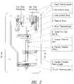
- FIG. 2illustrates a plan view of one embodiment of a thermo cycling microfluidic device of the present invention in accordance with principles of the present invention.
- FIG. 3illustrates a cross sectional view of the microfluidic device of FIG. 2 along lines 3 A- 3 A in accordance with principles of the present invention.
- FIGS. 4A-Cillustrate a flow chart and photographs of a thermal cycling microfluidic device in a manifold in accordance with principles of the present invention.
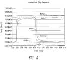
- FIG. 5is a graph illustrating the thermal chamber step response over time in accordance with principles of the present invention.
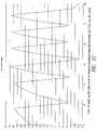
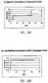
- FIG. 6is a graph illustrating the thermal rise over time of the thermal chamber in accordance with principles of the present invention.
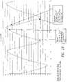
- FIG. 7is a graph illustrating the thermal fall over time of the thermal chamber in accordance with principles of the present invention.
- FIG. 8is a graph illustrating a three level PCR temperature modulation versus time in accordance with principles of the present invention.
- FIG. 9is a flow chart illustrating the components of a fluid thermal cycler in accordance with principles of the present invention.
- FIG. 10is a flow chart illustrating the components of a thermal electric cycler in accordance with principles of the present invention.
- FIG. 11is a schematic of a microfluidic test laminate with a thermocouple inserted into the amplification chamber in accordance with principles of the present invention.
- FIG. 12is a graph illustrating temperature variation over time when a TEC is placed directly 9 on a stainless steel table with no thermal interface material between the TEC and the microfluidic card in accordance with principles of the present invention.
- FIG. 13is a graph illustrating temperature variation overtime when a TEC is placed on a heat sink and a layer of graphite thermal interface pad is placed between the TEC and the laminate in accordance with principles of the present invention.
- FIG. 14is a photograph of the card of FIG. 13 in accordance with principles of the present invention.
- FIG. 15is a graph illustrating temperature variation over time when a TEC is placed on a heat sink and a graphite pad between the TEC and amplification chamber in accordance with principles of the present invention.
- FIG. 16is a close up of a portion of the graph of FIG. 15 .
- FIG. 17is a graph illustrating temperature variation over time when a TEC is placed on a Thermagap heat sink in accordance with principles of the present invention.
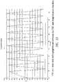
- FIG. 18is a screenshot of a Thermal Cycler Graphic Interface (GUI) in accordance with principles of the present invention.
- GUIThermal Cycler Graphic Interface
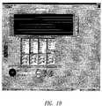
- FIG. 19is a screenshot of the GUI illustrating the addition or deletion of a Profile in accordance with principles of the present invention.
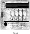
- FIG. 20is another screenshot of the GUI in accordance with principles of the present invention.
- FIG. 21is another screenshot of the GUI in accordance with principles of the present invention.
- FIG. 22is another screenshot of the GUI in accordance with principles of the present invention.
- FIG. 23is another screenshot of the GUI in accordance with principles of the present invention.
- FIG. 24is another screenshot of the GUI in accordance with principles of the present invention.
- FIG. 25is another screenshot of the GUI in accordance with principles of the present invention.
- FIG. 26is another screenshot of the GUI in accordance with principles of the present invention.
- FIG. 27is another screenshot of the GUI in accordance with principles of the present invention.
- FIG. 28is another screenshot of the GUI in accordance with principles of the present invention.
- FIG. 29is a cross section of a microfluidic card using a TEC for thermocycling in accordance with principles of the present invention.
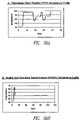
- FIG. 30A-Dare temperature profiles achieved on microfluidic cards of the present invention. Shown are a PCR profile, NASBA profile, reverse transcription profile, and LAMP profile.
- the present inventionis generally directed to a microfluidic device with a heating, cooling and heat cycling system on-board, a microfluidic device having an integrated heat exchanger circuit or a TEC used in connection with a microfluidic device to provide thermocycling.
- the portable microfluidic deviceis in the form of a card and has a heating, cooling and heat cycling system on-board such that the card can be used portably.
- the microfluidic cardincludes one or more reservoirs containing exothermic or endothermic material. Once the chemical process of the reservoir material is activated, the reservoir provides heating or cooling to specific locations of the microfluidic card. Multiple reservoirs may be included on a single card to provide varying temperatures.
- the assay chemicalscan be moved to the various reservoirs to create a thermal cycle useful in many biological reactions, including, for example, PCR.
- FIG. 1illustrates one exemplary embodiment of the present invention.
- Microfluidic card 100includes reservoir 110 for containing an exothermic or endothermic powder mixture.
- the reservoir 110has a fill hole 120 that may be covered, for example by tape, until the heating or cooling cycle is initiated.
- Several chemical and physical processes between different components of solid or liquid mixturesare known to be significantly exothermic or endothermic.
- a mixture of iron powder, activated charcoal powder, and cellulosecan provide a constant temperature of 60° C. over several hours.
- the temperature of an aqueous solutiondecreases if ammonium chloride is added.
- There are hundreds of different mixturesthat will, given the correct concentration, provide a certain heat absorption or output until the components are used up (i.e., the reaction is completed or the concentration of the components has equilibrated).
- an exothermic or endothermic mixture of materialis contained in reservoir 110 .
- a mixture of iron powder, activated charcoal powder, and cellulosewas used and (after 10 minutes) was found to maintain a temperature of 62° C. ( ⁇ 3° C.) for 4 hours.
- Such mixturescan be placed at various places on a microfluidic card, and can, upon exposure to either air, moisture, or another chemical, initiate the heating (or cooling) process.
- a practical application of such a cardwould include a passive or portable microfluidic card for performing biological reactions that needs incubations at a constant temperature, such as an immunoassay that would be kept at 37° C. for several minutes for incubation. Many other biological reactions are based on incubation of enzymes at 37° C. for minutes or hours. These include reverse transcriptases, DNA-dependent DNA polymerases, restriction enzymes, RNA-dependent DNA polymerases, loop-mediated isothermal amplification (LAMP), and nucleic acid sequence-based amplification (NASBA), among others.
- a passive or portable microfluidic cardfor performing biological reactions that needs incubations at a constant temperature, such as an immunoassay that would be kept at 37° C. for several minutes for incubation. Many other biological reactions are based on incubation of enzymes at 37° C. for minutes or hours. These include reverse transcriptases, DNA-dependent DNA polymerases, restriction enzymes, RNA-dependent DNA polymerases, loop-mediated isother
- Another embodimentwould include multiple areas with different mixtures providing hot and/or cold zones on a microfluidic card over which a microfluidic circuit would carry the desired fluid over hot and/or cold areas in any order and for any contact time desired.
- a thermal cycling experiment for nucleic acid amplificationcould be performed in this device. Different from current thermal cyclers that attempt to change the temperature at a static location where the samples are contained, this embodiment will circulate the sample to different locations of the card through microfluidics. These different locations would have the desired temperatures.
- a PCR cardwould have three locations at 95° C., 55° C. and 72° C. This application would result in shorter cycling times as the ramp-up times are much shorter (the times to go from one temperature to another). Ramping times contribute to more than 50% of the cycling times on typical thermal cyclers. Another benefit is the ability to use much smaller volumes. In a typical thermal cycler the typical volumes are 10-25 uL, mostly limited by the amount that can be measured by laboratory pipettes. In the practice of this invention, amplification of volumes as low as, for example, a microliter or even 100 mL may be achieved. Further, because of lower weight and power requirements, this invention allows the design of a handheld passive thermal cycling card that requires little or no external instrumentation for operation.
- PCR-based assayi.e., isolation and amplification
- the first two steps of a PCR-based assaycan now be integrated into a disposable plastic device the size of a credit card though microfluidics and microplumbing resulting in the following benefits: (1) minimization of contamination; (2) reduction of sample/reagent amounts; (3) reduction in assay time; (4) portability (including point of care application); (5) simplicity; (6) back and front integration (e.g., combination of sample preparation and analysis on single card); and (7) elimination of multiple analytical systems.
- PCR-based microfluidic cardthe steps previously required for DNA extraction which required a non-refrigerated centrifuge may be substituted by DNA separation through mixing, molecular diffusion and the use of embedded membranes or matrices.
- the instrumentswill be substituted, and in addition, the temperature can be changed through the use of chemical reactants.
- Micro-pipettesare eliminated with a microfluidic PCR card as fluids are moved by hydrostatic pressure. Mixing is performed through diffusion, and cell lysis is performed by mixing with lysing reagents, not in a microwave oven. A water bath is similarly not needed, as temperature may be changed through chemical reactants in the card.
- thermal cyclersare replaced by either on-board reservoirs or microfluidic circuits adjacent to the assay circuit. Further, significant reduction of space is provided as all of the steps will occur in the PCR card under contained sterile conditions, and separate clean rooms will not be required.
- the integrated, heat exchangeris a microfluidic circuit containing fluid that is either independently heated or cooled, or is an exothermic or endothermic material positioned adjacent to a microfluidic circuit containing assay fluid, such that the fluid in the adjacent circuit imparts a change in temperature to the assay fluid in an independent circuit.
- Both the heat exchanger circuit and the assay containing circuitare contained on the microfluidic card.
- the fluid in the heat exchanger circuitmay be circulated by connecting the card to a manifold of instrumentation to provide a pumping means.
- integral heating and coolingincludes two or more pump and valve-controlled microfluidic circuits in close proximity (e.g., one on top of the other or otherwise adjacent).
- One circuitallows the interdiffusion of specific quantities of a two-part heating or cooling mixture, and the other is a microfluidic circuit containing the assay chemicals that require heating and/or cooling.
- the exact temperaturecan be adjusted, and kept for as long as the two components of the heating mixture are flowing.
- FIG. 2One embodiment of such a rapid thermal cycler is the microfluidic card shown in FIG. 2 .
- This configurationenables thermal transition capability of PCR size thermal changes more than four times faster than standard thermal cyclers. These results have been experimentally determined and are demonstrated with real data showing ramping rates of up to 17° C./sec showing 50° C. change in less than 3 seconds, or a ramping rate of 17° C. per second.
- microfluidic card with active microfluidic circuitsfor providing heating and/or cooling.
- these systemsrequire relatively low power
- the microfluidic cardis of small size and the heating/cooling unit is targeted to be, for example, 4 cubic inches
- any intermediate temperature in the aqueous rangecan be achieved with an appropriate thermal controller (0-100° C.)
- aqueous samplescan be frozen as well as boiled.
- the microfluidic valve capabilitygiven their small size and the thermal insulation properties of the plastics used, provides the ability to rapidly change temperatures without having to change temperatures of large thermal masses in valves and card plastic.
- low thermal massallows very rapid thermal changes.
- FIG. 2is a top view of one embodiment of a thermal cycling heat exchanger test card is depicted. This specially designed and fabricated card was built to measure the effectiveness of the heating and cooling scheme.
- FIG. 3is a cross section taken along line 3 A- 3 A of the test card shown in FIG. 2 .
- FIG. 4Ais a flow chart of the test card.
- FIG. 4Bis a photograph of the test card inserted in a manifold.
- FIG. 4 ° C.is a photograph of the test card with embedded thermocouples.
- ColdIN-Ithe measured temperature of the circulating cold water at the card inlet. This is an indicator of the rise in temperature of the cold fluid on its way to the card under test. This temperature rise is not critical for these experiments, but will be minimized with design of a small closely coupled fluid heater/cooler.
- HotIN-Ithe measured temperature of the circulating hot water at the card inlet. This is an indicator of the drop in temperature of the hot fluid (to ambient room temp) on its way to the card under test.
- MixerThe temperature of the chamber used to equalize the mix of hot and cold fluids before running the fluid through the channels directly above and below the sample fluid. This indicates the time of commanded change in temperature by indicating the change in state of either the hot or cold fluid valves and of the temperature of the hot and cold mixture.
- FIG. 5is a graph of the thermal chamber temperature step response.
- the step responseis a standard linear system characterization of a control system.
- the open loop step response shown in FIG. 5indicates a rise and fall time that can characterize the maximum cycle times for the structure we are testing.
- the step responseis derived by equilibrating the chamber temperature with the cold fluid valve open, and then closing the cold fluid valve and at the same time opening the hot fluid valve for 50 seconds and then closing the hot fluid valve and again opening the cold fluid valve.
- FIG. 6is a graph of the chamber's thermal rise over time.
- the rise time of the chamber temperature responseis delayed by about 1 second from the thermal rise of the mixer heat exchanger fluid. This is mostly accounted for by the flow speed of the fluid and the separation of the thermocouples. Flow rate can be increased for reduced delay from driving temperature to response temperature.
- a 50° C. sample temperature riseis effected within 3 seconds.
- One protocol for PCRcalls for temperature plateaus of 50° C. transitioning to 95° C. to 75° C. and back to 50° C. With correctly heated and controlled driving fluids, this positive thermal rise could be achieved in less than 3 seconds.
- FIG. 7is a graph of the chamber's thermal fall over time.
- the fall time for the thermal exchangeachieves a 40° C. temperature drop in less than 3 seconds.
- a thermal drop of 20-30° C.is required.
- this 25 uL samplecould be thermally cycled through three PCR temperatures in approximately 10 seconds, thus allowing for the thirty or so cycles of PCR to occur in about 5 minutes.
- FIG. 8is a graph of the three level-type (e.g., PCR) modulation.
- a simple open loop three level temperature cycleis demonstrated by opening the hot and cold fluid valves simultaneously to achieve an intermediate temperature. This demonstrates the ability of the valving system to achieve intermediate temperatures between the hot and cold fluid limits.
- a valve control system utilizing a duty cycle modulation of the hot and cold valves with an appropriately designed mixermay achieve any intermediate temperature. It can also allow tailoring of the driving temperature function to achieve faster cycle times and stable intermediate temperatures.
- FIG. 9is a flow chart illustrating the flow of fluid in the fluid thermal cycler described in detail above.
- the thermal fluid approach to heating local areas on laminate cardshas several advantages.
- One main advantageis the ability to locate a thermal zone for amplification in a not fixed location on the card.
- a second advantageis the ability to “surround” or “cover” the amplification chamber with moving thermal fluid, assuring even and rapid heating of the sample.
- the systemhas two pumps, two heat exchangers with thermal control (hot and cold), a thermal fluid reservoir, related tubing connections, restrictors and capacitors to mitigate pulses from the pumps, a de bubbler circuit to remove bubbles created by heating a fluorocarbon thermal fluid, such as Fluorinert.
- FC-40Fluorinert FC-40 was tested as an alternative because of its inert properties and its relatively high boiling point of 155° C. FC-40 has a specific heat of one fourth that of water (per weight) and a thermal conductivity of about one tenth of water. FC-40 is extremely inert and volatile enough that spills and leaks evaporate readily. Those skilled in the art understand that many other thermal fluids can be used in accordance with the teachings of this invention.
- thermal fluidis not an efficient heat transfer material there are limits to how far from the entry port and how large the amplification chamber(s) can be. All components from the heat exchanger to the card have some thermal mass that has to be heated or cooled during thermal cycling. To accommodate a larger amplification area would require increasing flow or slowing down cycle rates.
- thermal cyclingmay be accomplished using a thermal electric cooler (TEC) such as a Peltier.
- TECthermal electric cooler
- FIG. 10illustrates a flow diagram of the components of the Thermal Electric Cycler of the present invention as further described below. This configuration was used to test the feasibility of using a TEC as a heating and cooling source for microfluidic amplification chambers for use with PCR and rtPCR.
- Equipment usedincluded a Power supply 0-20 VDC (Set to 7.5 VDC); DPDT switch to reverse current direction; Heat sink; digital voltmeter; TEC (Melcor CPO-8-63-06MM, 12 mm ⁇ 25 mm, Imax 2. 1A, V max 7.62 VDC); thermocouple; and Micronics “run motor” software and Thermocycler Dart, for data acquisition.
- One exemplary target profileHeat to 65-75° C. and hold for 60 seconds. Ramp as quickly as possible to 94-95° C., hold (soak) for 5 seconds; ramp down to 65-70° C., hold (soak) for another 5 seconds. Repeat previous two steps (94 and 72° C.). Total number of repeats estimated at 40 each.
- Temperature and soak timesare based on the chemistry chosen for the amplification.
- a second exemplary target profile95° C. for 3 minutes, 27° C. for 30 sec, 65° C. for 10 minutes. There is another 5 step variation of this with temperatures from 27 to 95 with varying times. But it illustrates the PID requirements.
- a third exemplary target profilehold a temperature for up to 90 minutes.
- a TECwas placed on a stainless steel table to act as a heat sink.
- a thermocouplewas taped to the top surface of the TEC. Data was taken as the TEC was cycled from hot to cold. This test yielded data that showed a transition time of 4.25 seconds to go from 60° C. to 95° C. or 8.65° C./sec. Cool down time was 3 seconds to go from 96° C. to 60° C. or 12° C./sec.
- a simple laminate cardwas designed with an amplification chamber capped by one layer of 0.004′′Mylar® (polyethylene terephthalate).
- the Mylar layeris sealed in place with a double-sided ACA adhesive layer.
- Mylarhas good transparency and can be used in devices where optical readout is desired. Also preferred for their transparency in the visual and UV spectrum in applications where fluorometric detection is required are cyclic polyolefins such as Topas® (Ticona Corp, Florence Ky.) and Zenor® (Zeon Chemicals, Tokyo JP). Both the thermoplastic and the ACA (adhesive-carrier-adhesive) film layers can be supplied as sheet stock or as roll stock for manual or continuous lamination assembly.
- roll stockis fed into an automated continuous assembler; the advantage of roll stock of Mylar and ACA films being that a “kiss” laser cut can be performed on the ACA film prior to assembly and unwanted cutouts of the adhesive film removed with the first release layer, thereby ensuring that heat transfer across the Mylar layer is unimpeded by the presence of a glue layer in areas where adhesive is not needed.
- the cutoutsgenerally conform to the outline of the amplification chambers so that the amplification chambers are not capped by the ACA layer.
- ACA roll stockis typically supplied as a 5-layer substrate, the outermost top and bottom release layers of which are removed from the underlying pressure sensitive adhesive layers and central core layer immediately before assembly. Individual laminated cards may also be manufactured manually from roll or sheet stock.
- thermocouplewas inserted into the amplification chamber and the chamber was filled with Fluorinert FC-40.
- the designed volume of the amplification chamberis approximately 10 uL. This is increased slightly because the thermocouple causes a bulge in the chamber. Actual volume is estimated between 15 and 20 uL.
- the thermocouplemonitors the temperature of the amplification chamber.
- the first testwas with the laminate placed directly against the TEC.
- An insulating padwas placed over the laminate and a 3.5 oz weight placed on top to provide some pressure.
- FIG. 13illustrates a close-up of some of the data in FIG. 12 .
- FIG. 13illustrates a card on TEC with heat sink and graphite pad.
- FIG. 14is a photograph of the card tested yielding the results in FIG. 13 .
- FIG. 15illustrates a TEC on a heat sink and a graphite pad between the TEC and Amplification chamber. Note that in the first figure, the heat up is more constant without the rate tapering off at the end (after the initial heat up). The cool down rate however does taper off.
- FIG. 16illustrates a close up of the above data. The total cycle time was 15.2 seconds.
- a TECmoves heat from one side to the other; in the process it adds heat (TECs draw quite a bit of current). If the cold side is against an already cold surface the heat transferred from that surface is minimal and the heating that takes place on the “hot” side is primarily from the electrical current passing through the TEC. This is evident in the first test where the TEC was directly in contact with a cool stainless steel table (around 17° C.). After several cycles the area under the TEC heats up slightly and the rise time from 70 to 95° C. is quicker.
- Cool down timeis rapid because there is enough temperature differential between the TEC and the table to move the heat away quickly.
- the heat sinkWhen the TEC is mounted on the heat sink, the heat sink is able to store heat that can be transferred quickly to the laminate. Thus the rise time is quicker. However the cool down time is longer because the temperature differential between the TEC and the sink can't carry away the excess heat very quickly.
- the aboveillustrates a thermal balance that must be achieved for efficient (and consistent) operation.
- the heat sinkshould have enough heat stored to transfer quickly to the laminate at the same time it should not be so hot that it slows down the cooling process.
- the graphite thermal interface material usedis the only material tested, other suitable materials may be used.
- the TEC used in these testswas a relatively inexpensive and inefficient one. Higher power TECs are readily available. The maximum temperature difference between hot and cold side is around 60° C. without cascading. In the present embodiment, we also consider using a cascaded (stacked) TEC. Some applications may need a 27° C. to 95° C. range.
- a cascaded TECmoves the heat to and from the card and prevents a heat buildup.
- the cycle time of 16 secondscan be improved on greatly with proper sized heat sinks, TECs, and more efficient thermal interface material. Even at 16 seconds 30 full cycles will only take 8 minutes.
- the TECis sized to match the amplifier area of the card.
- the above cycle testswere repeated using Parker Chomerics Thermagap material 61-02-0404-F574. (0.020′′ thick).
- the 574 seriesis a soft elastomer ( ⁇ 5 Shore A) needing only a pressure of 5 to 10 psi to provide a thermal conductivity of 1.6 W/m-K.
- the timing for a full cyclewas 13 about 14 seconds including a one second turn around time at top and bottom of the cycle. Thirty complete cycles would take 7 minutes. Rise rate 55° C./sec. Fall rate-4° C./sec. See the following graph shown in FIG. 17 . Note that the ramp up and ramp down require a “rounding off” at the target temperature to avoid overshoot. This can increase the overall cycle time significantly. A tight PID control loop can minimize this round off.
- the Thermal Cycler Graphic Interfaceallows the Engineer or Technician to develop and tune thermal profiles for assay development. Custom profiles can be developed for different heating and cooling requirements.
- the Graphdepicts the temperature at the Control Thermistor.
- the PID loopProportional Integral and Derivative
- Timingcan be set in the lower panel of each Profile.
- Datacan be recorded by pressing the “Save Data” button. Press the “Store Data” Button when you want to stop saving. Save as a CSV file.
- adding or deleting a Profile (element) in a seriescan be done by right clicking the PID panel near the D or P. Select insert or delete.
- the new elementis inserted between Profiles 2 and 3 .
- the TECWhen tuning a series of profiles it is sometimes advantageous to turn the TEC off for a few seconds. This can be particularly helpful when cooling down to avoid overshooting.
- the new Profilebecomes Profile 3 and the original Profile 3 becomes Profile 4 .
- the Start Profile lightis lit.
- the In Use lightindicates which profile is active. (The Power light would also be lit if this was not from a simulation.)
- the Count timerdisplays how long the Profile has been active.
- the number of Cycles to be performedis selected in the “Number of Cycles” box. Note that All Profile series must have at least one box checked indicating it is to be cycled. By indicating 1 cycle in the “Number of Cycles” box the Entire series can be run from start to finish without any repeats. A long series of Profiles to cycle can be strung together. Individual not repeated Profiles can be placed before and after the cycled series.
- a second thermistormounted on the top surface of the TEC. This is monitored to guard against the overheating or cooling of the TEC. It is important to always have the control thermistor in place when running the Cycler.
- FIG. 25illustrates an example of using two Profiles to reach a temperature with a minimum of overshoot.
- a lower PProportional gain
- the controller outputis lowered and the temperature does not overshoot the target.
- the TECis driven down to 58.5° C. Because of latency in the system it will overshoot and reverse the temperature in the TEC. The heat going into the TEC will reduce the overshoot.
- the Set Temperature, Proportional gain, and timingit is possible to get the temperature to level out at the desired temperature without overshooting. Then the Profile to hold that temperature is invoked. Note that unless the output is turned off (see above) the controller will be trying to drive the TEC either up or down to the set temperature. Given enough time this will level out to a “flat line” but for rapid thermal cycling it is helpful to Tune the ramp up and down.
- FIGS. 26 through 28illustrate various aspects of the GUI.
- the last Opened filescan be selected.
- the displayed graph timecan be selected from 30 seconds to 5 minutes.
- “Room temperature”can be selected, as well as output on or off. Note the controller output is turned off after a series is completed. It is often helpful to have a room temperature Profile at the end of a series. When the controller is turned on it drives the TEC to the last “Set temperature.”
- FIG. 29is a cross section of a microfluidic card using a TEC for thermocycling in accordance with principles of the present invention as discussed above.
- multiple amplification reservoirs or fluid chambersare simultaneously cycled by the TEC.
- the amplification reservoirsare contained between layers of PET material and an ACA (adhesive-carrier-adhesive) material to provide a disposable microfluidic card.
- a heat spacer or heat spreadermay be used between the TEC and the amplification reservoirs in order to provide a more uniform heat across the TEC surface.
- the heat spreaderwill ultimately be determined by the thermal profile of the TEC, but one exemplary heat spreader is a layer of PTFE between layers of copper, however those skilled in the art will understand that many variations of heat spreaders are acceptable.
- the interface pad illustrated in FIG. 29is a thermal pad to more efficiently transfer heat to the microfluidic card.
- the thermal grease between the TEC and the heat spreader or spaceris know to those in the art to further enhance heat transfer.
- FIG. 30Ashows a Polymerase Chain Reaction (PCR) Temperature Profile.
- the profiledemonstrates: 1) Consistent; 2) Adjustable and accurate temperature for anneal step (lowest T); 3) Adjustable hold time for anneal step; 4) Adjustable hold time at extension step (72° C.); 5) Do not exceed 95° C. (prevents denaturing of enzyme), and 6) Rapid cycling.
- PCRPolymerase Chain Reaction
- FIG. 30Bshows a Nucleic Acid Sequence Based Analysis (NASBA) Temperature Profile.
- the profiledemonstrates: 1) Stable 40 +/ ⁇ 1.0° C. temperature (>42° C. denatures enzyme); 2) Adjustable hold times for 65° C. and 40° C., with 90 minutes maximum for 40° C.; 3) 65° C. or greater is OK; 4) 2 to 5 minute hold at 65° C. is standard, but shorter may be OK; 5) Consistent time to 40° C. after 65° C. (for programmed enzyme addition), and 6) Shorter is better, but 1-2 minutes for cooling from 65 to 40° C. is OK.
- Current block heaters used with DARTtake-10 minutes-current thermal cyclers take about 1 minute to cool.
- FIG. 30Cshows a Reverse Transcriptase (rt) Temperature Profile.
- the profiledemonstrates: 1) Stable 47° C. temperature with zero or minimal overshoot; 2) Adjustable hold time for 47° C., with 60 min maximum, and 3) Rapid rise to 75° C. or higher for 10 minutes.
- FIG. 30Dshows a Loop Mediated Amplification (LAMP) Temperature Profile.
- LAMPLoop Mediated Amplification
Landscapes
- Chemical & Material Sciences (AREA)
- Health & Medical Sciences (AREA)
- Dispersion Chemistry (AREA)
- Analytical Chemistry (AREA)
- General Health & Medical Sciences (AREA)
- Hematology (AREA)
- Clinical Laboratory Science (AREA)
- Chemical Kinetics & Catalysis (AREA)
- Apparatus Associated With Microorganisms And Enzymes (AREA)
Abstract
Description
- Communication via PC
- RS-232
- USB
- GPIB
Thermistor sensors 20° C. to 100° C.- Ability to drive TEC up to temperature and down to temperature.
- Current load 3.7 amps at 19VDC (optionally 7.4 amps)
- Adjustable voltage output 0-20 vdc with current limits (or ability to use separate power supply)
- Ability to poll and collect data.
- Fast PID loop (P=1° C. to 200° C., I=1 sec or less, D=1 sec or less)
- Ability to use different PID loop for heating and cooling.
- Ramp and soak to three temperatures minimum.
Ramp rate 6° C. per second or faster.
Claims (12)
Priority Applications (1)
| Application Number | Priority Date | Filing Date | Title |
|---|---|---|---|
| US12/199,613US7648835B2 (en) | 2003-06-06 | 2008-08-27 | System and method for heating, cooling and heat cycling on microfluidic device |
Applications Claiming Priority (3)
| Application Number | Priority Date | Filing Date | Title |
|---|---|---|---|
| US47635203P | 2003-06-06 | 2003-06-06 | |
| US10/862,826US7544506B2 (en) | 2003-06-06 | 2004-06-07 | System and method for heating, cooling and heat cycling on microfluidic device |
| US12/199,613US7648835B2 (en) | 2003-06-06 | 2008-08-27 | System and method for heating, cooling and heat cycling on microfluidic device |
Related Parent Applications (1)
| Application Number | Title | Priority Date | Filing Date |
|---|---|---|---|
| US10/862,826Continuation-In-PartUS7544506B2 (en) | 2003-06-06 | 2004-06-07 | System and method for heating, cooling and heat cycling on microfluidic device |
Publications (2)
| Publication Number | Publication Date |
|---|---|
| US20090081771A1 US20090081771A1 (en) | 2009-03-26 |
| US7648835B2true US7648835B2 (en) | 2010-01-19 |
Family
ID=40472084
Family Applications (1)
| Application Number | Title | Priority Date | Filing Date |
|---|---|---|---|
| US12/199,613Expired - LifetimeUS7648835B2 (en) | 2003-06-06 | 2008-08-27 | System and method for heating, cooling and heat cycling on microfluidic device |
Country Status (1)
| Country | Link |
|---|---|
| US (1) | US7648835B2 (en) |
Cited By (39)
| Publication number | Priority date | Publication date | Assignee | Title |
|---|---|---|---|---|
| US20100215961A1 (en)* | 2009-02-23 | 2010-08-26 | Nadine Aubry | Methods, apparatus and systems for concentration, separation and removal of particles at/from the surface of drops |
| US20100279299A1 (en)* | 2009-04-03 | 2010-11-04 | Helixis, Inc. | Devices and Methods for Heating Biological Samples |
| WO2011094577A2 (en) | 2010-01-29 | 2011-08-04 | Micronics, Inc. | Sample-to-answer microfluidic cartridge |
| CN104315241A (en)* | 2014-08-20 | 2015-01-28 | 中国检验检疫科学研究院 | Microfluidic micro valve and driving device |
| WO2015138343A1 (en)* | 2014-03-10 | 2015-09-17 | Click Diagnostics, Inc. | Cartridge-based thermocycler |
| US9222623B2 (en) | 2013-03-15 | 2015-12-29 | Genmark Diagnostics, Inc. | Devices and methods for manipulating deformable fluid vessels |
| US9415392B2 (en) | 2009-03-24 | 2016-08-16 | The University Of Chicago | Slip chip device and methods |
| US9447461B2 (en) | 2009-03-24 | 2016-09-20 | California Institute Of Technology | Analysis devices, kits, and related methods for digital quantification of nucleic acids and other analytes |
| US9464319B2 (en) | 2009-03-24 | 2016-10-11 | California Institute Of Technology | Multivolume devices, kits and related methods for quantification of nucleic acids and other analytes |
| US9498778B2 (en) | 2014-11-11 | 2016-11-22 | Genmark Diagnostics, Inc. | Instrument for processing cartridge for performing assays in a closed sample preparation and reaction system |
| US9562262B2 (en) | 2011-03-08 | 2017-02-07 | UNIVERSITé LAVAL | Fluidic centripetal device |
| US9599613B2 (en) | 2011-07-20 | 2017-03-21 | University Of Washington Through Its Center For Commercialization | Photonic blood typing |
| US9598722B2 (en) | 2014-11-11 | 2017-03-21 | Genmark Diagnostics, Inc. | Cartridge for performing assays in a closed sample preparation and reaction system |
| US9623415B2 (en) | 2014-12-31 | 2017-04-18 | Click Diagnostics, Inc. | Devices and methods for molecular diagnostic testing |
| USD799715S1 (en) | 2015-10-23 | 2017-10-10 | Gene POC, Inc. | Fluidic centripetal device |
| USD800331S1 (en) | 2016-06-29 | 2017-10-17 | Click Diagnostics, Inc. | Molecular diagnostic device |
| USD800914S1 (en) | 2016-06-30 | 2017-10-24 | Click Diagnostics, Inc. | Status indicator for molecular diagnostic device |
| USD800913S1 (en) | 2016-06-30 | 2017-10-24 | Click Diagnostics, Inc. | Detection window for molecular diagnostic device |
| US9957553B2 (en) | 2012-10-24 | 2018-05-01 | Genmark Diagnostics, Inc. | Integrated multiplex target analysis |
| US10005080B2 (en) | 2014-11-11 | 2018-06-26 | Genmark Diagnostics, Inc. | Instrument and cartridge for performing assays in a closed sample preparation and reaction system employing electrowetting fluid manipulation |
| US10031138B2 (en) | 2012-01-20 | 2018-07-24 | University Of Washington Through Its Center For Commercialization | Hierarchical films having ultra low fouling and high recognition element loading properties |
| US10065186B2 (en) | 2012-12-21 | 2018-09-04 | Micronics, Inc. | Fluidic circuits and related manufacturing methods |
| US10087440B2 (en) | 2013-05-07 | 2018-10-02 | Micronics, Inc. | Device for preparation and analysis of nucleic acids |
| US10190153B2 (en) | 2013-05-07 | 2019-01-29 | Micronics, Inc. | Methods for preparation of nucleic acid-containing samples using clay minerals and alkaline solutions |
| US10196700B2 (en) | 2009-03-24 | 2019-02-05 | University Of Chicago | Multivolume devices, kits and related methods for quantification and detection of nucleic acids and other analytes |
| US10386377B2 (en) | 2013-05-07 | 2019-08-20 | Micronics, Inc. | Microfluidic devices and methods for performing serum separation and blood cross-matching |
| US10436713B2 (en) | 2012-12-21 | 2019-10-08 | Micronics, Inc. | Portable fluorescence detection system and microassay cartridge |
| US10495656B2 (en) | 2012-10-24 | 2019-12-03 | Genmark Diagnostics, Inc. | Integrated multiplex target analysis |
| US10518262B2 (en) | 2012-12-21 | 2019-12-31 | Perkinelmer Health Sciences, Inc. | Low elasticity films for microfluidic use |
| USD881409S1 (en) | 2013-10-24 | 2020-04-14 | Genmark Diagnostics, Inc. | Biochip cartridge |
| US10675623B2 (en) | 2016-06-29 | 2020-06-09 | Visby Medical, Inc. | Devices and methods for the detection of molecules using a flow cell |
| US10987674B2 (en) | 2016-04-22 | 2021-04-27 | Visby Medical, Inc. | Printed circuit board heater for an amplification module |
| US11162130B2 (en) | 2017-11-09 | 2021-11-02 | Visby Medical, Inc. | Portable molecular diagnostic device and methods for the detection of target viruses |
| US11193119B2 (en) | 2016-05-11 | 2021-12-07 | Visby Medical, Inc. | Devices and methods for nucleic acid extraction |
| US11352675B2 (en) | 2020-01-03 | 2022-06-07 | Visby Medical, Inc. | Devices and methods for antibiotic susceptability testing |
| US12174239B2 (en) | 2021-11-05 | 2024-12-24 | Microsoft Technology Licensing, Llc | Thermal testing system having safety feature(s) and multiple independently controlled thermoelectric coolers |
| USD1055307S1 (en) | 2021-08-13 | 2024-12-24 | Visby Medical, Inc. | Molecular diagnostic device |
| US12239993B2 (en) | 2018-09-03 | 2025-03-04 | Visby Medical, Inc. | Devices and methods for antibiotic susceptibility testing |
| US12263478B2 (en) | 2019-04-28 | 2025-04-01 | Visby Medical, Inc. | Molecular diagnostic devices with digital detection capability and wireless connectivity |
Families Citing this family (60)
| Publication number | Priority date | Publication date | Assignee | Title |
|---|---|---|---|---|
| DE102010028769A1 (en) | 2010-05-07 | 2011-11-10 | Pvt Probenverteiltechnik Gmbh | System for transporting containers between different stations and container carriers |
| WO2013101295A2 (en)* | 2011-05-17 | 2013-07-04 | Canon U.S. Life Sciences, Inc. | Systems and methods using external heater systems in microfluidic devices |
| CN102220226B (en)* | 2011-05-23 | 2013-07-24 | 北京工业大学 | Two-path temperature control polymerase chain reactor and real-time detection device |
| EP2589968A1 (en) | 2011-11-04 | 2013-05-08 | Roche Diagnostics GmbH | Laboratory sample distribution system, laboratory system and method of operating |
| EP2589967A1 (en) | 2011-11-04 | 2013-05-08 | Roche Diagnostics GmbH | Laboratory sample distribution system and corresponding method of operation |
| EP2589966A1 (en) | 2011-11-04 | 2013-05-08 | Roche Diagnostics GmbH | Laboratory sample distribution system and corresponding method of operation |
| WO2013126379A1 (en)* | 2012-02-21 | 2013-08-29 | Anthrogenesis Corporation | Devices and methods for thawing biological material |
| JP6027321B2 (en)* | 2012-03-06 | 2016-11-16 | 公益財団法人神奈川科学技術アカデミー | High-speed gene amplification detector |
| WO2015003722A1 (en)* | 2013-07-10 | 2015-01-15 | Delta Dansk Elektronik, Lys & Akustik | Single-use device with a reaction chamber and a method for controlling the temperature in the device and uses thereof |
| DE102014202843B3 (en) | 2014-02-17 | 2014-11-06 | Roche Pvt Gmbh | Transport device, sample distribution system and laboratory automation system |
| DE102014202838B3 (en) | 2014-02-17 | 2014-11-06 | Roche Pvt Gmbh | Transport device, sample distribution system and laboratory automation system |
| EP2927167B1 (en) | 2014-03-31 | 2018-04-18 | F. Hoffmann-La Roche AG | Dispatch device, sample distribution system and laboratory automation system |
| EP2927695B1 (en) | 2014-03-31 | 2018-08-22 | Roche Diagniostics GmbH | Sample distribution system and laboratory automation system |
| EP2927168A1 (en)* | 2014-03-31 | 2015-10-07 | Roche Diagniostics GmbH | Transport device, sample distribution system and laboratory automation system |
| EP2927625A1 (en) | 2014-03-31 | 2015-10-07 | Roche Diagniostics GmbH | Sample distribution system and laboratory automation system |
| EP2927163B1 (en) | 2014-03-31 | 2018-02-28 | Roche Diagnostics GmbH | Vertical conveyor, sample distribution system and laboratory automation system |
| EP2957914B1 (en) | 2014-06-17 | 2018-01-03 | Roche Diagnostics GmbH | Laboratory sample distribution system and laboratory automation system |
| EP2977766A1 (en) | 2014-07-24 | 2016-01-27 | Roche Diagniostics GmbH | Laboratory sample distribution system and laboratory automation system |
| EP2995960B1 (en) | 2014-09-09 | 2020-07-15 | Roche Diagniostics GmbH | Laboratory sample distribution system and method for calibrating magnetic sensors |
| EP2995580A1 (en) | 2014-09-09 | 2016-03-16 | Roche Diagniostics GmbH | Laboratory sample distribution system and laboratory automation system |
| US9952242B2 (en) | 2014-09-12 | 2018-04-24 | Roche Diagnostics Operations, Inc. | Laboratory sample distribution system and laboratory automation system |
| EP2995958A1 (en) | 2014-09-15 | 2016-03-16 | Roche Diagniostics GmbH | Method of operating a laboratory sample distribution system, laboratory sample distribution system and laboratory automation system |
| EP3006943B1 (en) | 2014-10-07 | 2020-04-22 | Roche Diagniostics GmbH | Module for a laboratory sample distribution system, laboratory sample distribution system and laboratory automation system |
| EP3016116A1 (en) | 2014-11-03 | 2016-05-04 | Roche Diagniostics GmbH | Printed circuit board arrangement, coil for a laboratory sample distribution system, laboratory sample distribution system and laboratory automation system |
| EP3070479B1 (en) | 2015-03-16 | 2019-07-03 | Roche Diagniostics GmbH | Transport carrier, laboratory cargo distribution system and laboratory automation system |
| EP3073270B1 (en) | 2015-03-23 | 2019-05-29 | Roche Diagniostics GmbH | Laboratory sample distribution system and laboratory automation system |
| EP3096146A1 (en) | 2015-05-22 | 2016-11-23 | Roche Diagniostics GmbH | Method of operating a laboratory sample distribution system, laboratory sample distribution system and laboratory automation system |
| EP3096145B1 (en) | 2015-05-22 | 2019-09-04 | Roche Diagniostics GmbH | Method of operating a laboratory automation system and laboratory automation system |
| EP3095739A1 (en) | 2015-05-22 | 2016-11-23 | Roche Diagniostics GmbH | Method of operating a laboratory sample distribution system, laboratory sample distribution system and laboratory automation system |
| EP3112874A1 (en) | 2015-07-02 | 2017-01-04 | Roche Diagnostics GmbH | Storage module, method of operating a laboratory automation system and laboratory automation system |
| EP3121603A1 (en) | 2015-07-22 | 2017-01-25 | Roche Diagnostics GmbH | Sample container carrier, laboratory sample distribution system and laboratory automation system |
| EP3139175B1 (en) | 2015-09-01 | 2021-12-15 | Roche Diagnostics GmbH | Laboratory cargo distribution system, laboratory automation system and method of operating a laboratory cargo distribution system |
| EP3153866A1 (en) | 2015-10-06 | 2017-04-12 | Roche Diagnostics GmbH | Method of determining a handover position and laboratory automation system |
| EP3153867B1 (en) | 2015-10-06 | 2018-11-14 | Roche Diagniostics GmbH | Method of configuring a laboratory automation system, laboratory sample distribution system and laboratory automation system |
| EP3156352B1 (en) | 2015-10-13 | 2019-02-27 | Roche Diagniostics GmbH | Laboratory sample distribution system and laboratory automation system |
| EP3156353B1 (en) | 2015-10-14 | 2019-04-03 | Roche Diagniostics GmbH | Method of rotating a sample container carrier, laboratory sample distribution system and laboratory automation system |
| EP3211428A1 (en) | 2016-02-26 | 2017-08-30 | Roche Diagnostics GmbH | Transport device unit for a laboratory sample distribution system |
| EP3211429A1 (en) | 2016-02-26 | 2017-08-30 | Roche Diagnostics GmbH | Transport device having a tiled driving surface |
| EP3211430A1 (en) | 2016-02-26 | 2017-08-30 | Roche Diagnostics GmbH | Transport device with base plate modules |
| WO2017210556A1 (en)* | 2016-06-02 | 2017-12-07 | Integrated Nano-Technologies, Inc. | System and method for optimizing heat transfer for target amplification within a diagnostic assay system |
| CN109196363A (en) | 2016-06-03 | 2019-01-11 | 豪夫迈·罗氏有限公司 | Laboratory sample distribution system and laboratory automation system |
| EP3255519B1 (en) | 2016-06-09 | 2019-02-20 | Roche Diagniostics GmbH | Laboratory sample distribution system and method of operating a laboratory sample distribution system |
| EP3260867A1 (en) | 2016-06-21 | 2017-12-27 | Roche Diagnostics GmbH | Method of setting a handover position and laboratory automation system |
| JP6752350B2 (en) | 2016-08-04 | 2020-09-09 | エフ.ホフマン−ラ ロシュ アーゲーF. Hoffmann−La Roche Aktiengesellschaft | Laboratory sample distribution system and laboratory automation system |
| EP3330717B1 (en) | 2016-12-01 | 2022-04-06 | Roche Diagnostics GmbH | Laboratory sample distribution system and laboratory automation system |
| EP3343232B1 (en) | 2016-12-29 | 2021-09-15 | Roche Diagnostics GmbH | Laboratory sample distribution system and laboratory automation system |
| EP3355065B1 (en) | 2017-01-31 | 2021-08-18 | Roche Diagnostics GmbH | Laboratory sample distribution system and laboratory automation system |
| EP3357842B1 (en) | 2017-02-03 | 2022-03-23 | Roche Diagnostics GmbH | Laboratory automation system |
| EP3410123B1 (en) | 2017-06-02 | 2023-09-20 | Roche Diagnostics GmbH | Method of operating a laboratory sample distribution system, laboratory sample distribution system and laboratory automation system |
| EP3428653B1 (en) | 2017-07-13 | 2021-09-15 | Roche Diagnostics GmbH | Method of operating a laboratory sample distribution system, laboratory sample distribution system and laboratory automation system |
| EP3456415B1 (en) | 2017-09-13 | 2021-10-20 | Roche Diagnostics GmbH | Sample container carrier, laboratory sample distribution system and laboratory automation system |
| EP3457144B1 (en) | 2017-09-13 | 2021-10-20 | Roche Diagnostics GmbH | Sample container carrier, laboratory sample distribution system and laboratory automation system |
| EP3537159B1 (en) | 2018-03-07 | 2022-08-31 | Roche Diagnostics GmbH | Method of operating a laboratory sample distribution system, laboratory sample distribution system and laboratory automation system |
| EP3540443B1 (en) | 2018-03-16 | 2023-08-30 | Roche Diagnostics GmbH | Laboratory system, laboratory sample distribution system and laboratory automation system |
| EP3610947B1 (en)* | 2018-08-17 | 2021-04-21 | F. Hoffmann-La Roche AG | Microfluidic system for digital polymerase chain reaction of a biological sample, and respective method |
| EP3925911B1 (en) | 2020-06-19 | 2023-05-24 | Roche Diagnostics GmbH | Laboratory sample distribution system and corresponding method of operation |
| EP3940388B1 (en) | 2020-07-15 | 2024-04-10 | Roche Diagnostics GmbH | Laboratory sample distribution system and method for operating the same |
| EP4237150A4 (en)* | 2020-10-27 | 2024-09-25 | Canon Virginia, Inc. | Methods and systems for thermal cycling |
| EP4001923B1 (en) | 2020-11-23 | 2024-06-05 | Roche Diagnostics GmbH | Laboratory sample distribution system and laboratory automation system |
| US11747356B2 (en) | 2020-12-21 | 2023-09-05 | Roche Diagnostics Operations, Inc. | Support element for a modular transport plane, modular transport plane, and laboratory distribution system |
Citations (51)
| Publication number | Priority date | Publication date | Assignee | Title |
|---|---|---|---|---|
| US5498392A (en) | 1992-05-01 | 1996-03-12 | Trustees Of The University Of Pennsylvania | Mesoscale polynucleotide amplification device and method |
| US5587128A (en) | 1992-05-01 | 1996-12-24 | The Trustees Of The University Of Pennsylvania | Mesoscale polynucleotide amplification devices |
| US5639423A (en) | 1992-08-31 | 1997-06-17 | The Regents Of The University Of Calfornia | Microfabricated reactor |
| WO1997027324A1 (en) | 1996-01-24 | 1997-07-31 | Sarnoff Corporation | Parallel reaction cassette and associated devices |
| US5716852A (en) | 1996-03-29 | 1998-02-10 | University Of Washington | Microfabricated diffusion-based chemical sensor |
| US5724404A (en) | 1995-07-03 | 1998-03-03 | Garcia; Max | Integrated international telephone circuit monitoring system |
| US5726751A (en) | 1995-09-27 | 1998-03-10 | University Of Washington | Silicon microchannel optical flow cytometer |
| US5726026A (en) | 1992-05-01 | 1998-03-10 | Trustees Of The University Of Pennsylvania | Mesoscale sample preparation device and systems for determination and processing of analytes |
| US5747349A (en) | 1996-03-20 | 1998-05-05 | University Of Washington | Fluorescent reporter beads for fluid analysis |
| US5748827A (en) | 1996-10-23 | 1998-05-05 | University Of Washington | Two-stage kinematic mount |
| WO1998050147A1 (en) | 1997-05-09 | 1998-11-12 | The Regents Of The University Of California | Peltier-assisted microfabricated reaction chambers for thermal cycling |
| WO1999012016A1 (en) | 1997-09-02 | 1999-03-11 | Caliper Technologies Corporation | Microfluidic system with electrofluidic and electrothermal controls |
| US5922210A (en) | 1995-06-16 | 1999-07-13 | University Of Washington | Tangential flow planar microfabricated fluid filter and method of using thereof |
| US5932100A (en) | 1995-06-16 | 1999-08-03 | University Of Washington | Microfabricated differential extraction device and method |
| US5939312A (en) | 1995-05-24 | 1999-08-17 | Biometra Biomedizinische Analytik Gmbh | Miniaturized multi-chamber thermocycler |
| US5948684A (en) | 1997-03-31 | 1999-09-07 | University Of Washington | Simultaneous analyte determination and reference balancing in reference T-sensor devices |
| US5958349A (en) | 1997-02-28 | 1999-09-28 | Cepheid | Reaction vessel for heat-exchanging chemical processes |
| US5971158A (en) | 1996-06-14 | 1999-10-26 | University Of Washington | Absorption-enhanced differential extraction device |
| US5974867A (en) | 1997-06-13 | 1999-11-02 | University Of Washington | Method for determining concentration of a laminar sample stream |
| US6007775A (en) | 1997-09-26 | 1999-12-28 | University Of Washington | Multiple analyte diffusion based chemical sensor |
| US6018616A (en) | 1998-02-23 | 2000-01-25 | Applied Materials, Inc. | Thermal cycling module and process using radiant heat |
| US6020187A (en) | 1996-02-16 | 2000-02-01 | Tam; Joseph Wing On | Flow through nucleic acid hybridisation device |
| US6054277A (en) | 1996-05-08 | 2000-04-25 | Regents Of The University Of Minnesota | Integrated microchip genetic testing system |
| US6126804A (en) | 1997-09-23 | 2000-10-03 | The Regents Of The University Of California | Integrated polymerase chain reaction/electrophoresis instrument |
| US6180372B1 (en) | 1997-04-23 | 2001-01-30 | Bruker Daltonik Gmbh | Method and devices for extremely fast DNA replication by polymerase chain reactions (PCR) |
| US6192596B1 (en) | 1999-03-08 | 2001-02-27 | Battelle Memorial Institute | Active microchannel fluid processing unit and method of making |
| WO2001031053A1 (en) | 1999-10-22 | 2001-05-03 | Aclara Biosciences, Inc. | Microfluidic card thermal control |
| WO2001041931A2 (en) | 1999-12-09 | 2001-06-14 | Motorola, Inc. | Multilayered microfluidic devices for analyte reactions |
| US6261431B1 (en) | 1998-12-28 | 2001-07-17 | Affymetrix, Inc. | Process for microfabrication of an integrated PCR-CE device and products produced by the same |
| EP1125630A2 (en) | 2000-02-14 | 2001-08-22 | CPC Cellular Process Chemistry Systems GmbH | Microreactor with improved heat exchanger |
| US6303343B1 (en) | 1999-04-06 | 2001-10-16 | Caliper Technologies Corp. | Inefficient fast PCR |
| US20010046701A1 (en) | 2000-05-24 | 2001-11-29 | Schulte Thomas H. | Nucleic acid amplification and detection using microfluidic diffusion based structures |
| US6403037B1 (en) | 2000-02-04 | 2002-06-11 | Cepheid | Reaction vessel and temperature control system |
| US6420143B1 (en) | 1998-02-13 | 2002-07-16 | Caliper Technologies Corp. | Methods and systems for performing superheated reactions in microscale fluidic systems |
| US6432695B1 (en) | 2001-02-16 | 2002-08-13 | Institute Of Microelectronics | Miniaturized thermal cycler |
| US6440725B1 (en) | 1997-12-24 | 2002-08-27 | Cepheid | Integrated fluid manipulation cartridge |
| WO2002085777A2 (en) | 2001-04-21 | 2002-10-31 | Peter Prechtl | Device for producing and/or preparing a fuel for a fuel cell |
| WO2003004162A1 (en) | 2001-07-02 | 2003-01-16 | Gene Logic, Inc. | Flow-thru chip cartridge, chip holder, system & method thereof |
| US6509186B1 (en) | 2001-02-16 | 2003-01-21 | Institute Of Microelectronics | Miniaturized thermal cycler |
| US6541274B2 (en) | 1999-03-08 | 2003-04-01 | Caliper Technologies Corp. | Integrated devices and method of use for performing temperature controlled reactions and analyses |
| US6572830B1 (en) | 1998-10-09 | 2003-06-03 | Motorola, Inc. | Integrated multilayered microfludic devices and methods for making the same |
| US20030138941A1 (en) | 2001-10-26 | 2003-07-24 | Haiqing Gong | Sample preparation integrated chip |
| US6613560B1 (en) | 1994-10-19 | 2003-09-02 | Agilent Technologies, Inc. | PCR microreactor for amplifying DNA using microquantities of sample fluid |
| US20040029258A1 (en) | 2002-04-11 | 2004-02-12 | Paul Heaney | Methods and devices for performing chemical reactions on a solid support |
| US6699713B2 (en) | 2000-01-04 | 2004-03-02 | The Regents Of The University Of California | Polymerase chain reaction system |
| US6762049B2 (en) | 2001-07-05 | 2004-07-13 | Institute Of Microelectronics | Miniaturized multi-chamber thermal cycler for independent thermal multiplexing |
| US20040151629A1 (en) | 2003-01-31 | 2004-08-05 | Grant Pease | Microfluidic device with thin-film electronic devices |
| US6787338B2 (en) | 1990-06-04 | 2004-09-07 | The University Of Utah | Method for rapid thermal cycling of biological samples |
| US6960437B2 (en) | 2001-04-06 | 2005-11-01 | California Institute Of Technology | Nucleic acid amplification utilizing microfluidic devices |
| US7018830B2 (en) | 1992-05-01 | 2006-03-28 | The Trustees Of The University Of Pennsylvania | Device and method for the detection of an analyte utilizing mesoscale flow systems |
| US7544506B2 (en)* | 2003-06-06 | 2009-06-09 | Micronics, Inc. | System and method for heating, cooling and heat cycling on microfluidic device |
- 2008
- 2008-08-27USUS12/199,613patent/US7648835B2/ennot_activeExpired - Lifetime
Patent Citations (55)
| Publication number | Priority date | Publication date | Assignee | Title |
|---|---|---|---|---|
| US6787338B2 (en) | 1990-06-04 | 2004-09-07 | The University Of Utah | Method for rapid thermal cycling of biological samples |
| US5726026A (en) | 1992-05-01 | 1998-03-10 | Trustees Of The University Of Pennsylvania | Mesoscale sample preparation device and systems for determination and processing of analytes |
| US5587128A (en) | 1992-05-01 | 1996-12-24 | The Trustees Of The University Of Pennsylvania | Mesoscale polynucleotide amplification devices |
| US5498392A (en) | 1992-05-01 | 1996-03-12 | Trustees Of The University Of Pennsylvania | Mesoscale polynucleotide amplification device and method |
| US7018830B2 (en) | 1992-05-01 | 2006-03-28 | The Trustees Of The University Of Pennsylvania | Device and method for the detection of an analyte utilizing mesoscale flow systems |
| US5955029A (en) | 1992-05-01 | 1999-09-21 | Trustees Of The University Of Pennsylvania | Mesoscale polynucleotide amplification device and method |
| US5639423A (en) | 1992-08-31 | 1997-06-17 | The Regents Of The University Of Calfornia | Microfabricated reactor |
| US6613560B1 (en) | 1994-10-19 | 2003-09-02 | Agilent Technologies, Inc. | PCR microreactor for amplifying DNA using microquantities of sample fluid |
| US5939312A (en) | 1995-05-24 | 1999-08-17 | Biometra Biomedizinische Analytik Gmbh | Miniaturized multi-chamber thermocycler |
| US5932100A (en) | 1995-06-16 | 1999-08-03 | University Of Washington | Microfabricated differential extraction device and method |
| US6387290B1 (en) | 1995-06-16 | 2002-05-14 | University Of Washington | Tangential flow planar microfabricated fluid filter |
| US5922210A (en) | 1995-06-16 | 1999-07-13 | University Of Washington | Tangential flow planar microfabricated fluid filter and method of using thereof |
| US5724404A (en) | 1995-07-03 | 1998-03-03 | Garcia; Max | Integrated international telephone circuit monitoring system |
| US5726751A (en) | 1995-09-27 | 1998-03-10 | University Of Washington | Silicon microchannel optical flow cytometer |
| WO1997027324A1 (en) | 1996-01-24 | 1997-07-31 | Sarnoff Corporation | Parallel reaction cassette and associated devices |
| US6020187A (en) | 1996-02-16 | 2000-02-01 | Tam; Joseph Wing On | Flow through nucleic acid hybridisation device |
| US5747349A (en) | 1996-03-20 | 1998-05-05 | University Of Washington | Fluorescent reporter beads for fluid analysis |
| US5972710A (en) | 1996-03-29 | 1999-10-26 | University Of Washington | Microfabricated diffusion-based chemical sensor |
| US6171865B1 (en) | 1996-03-29 | 2001-01-09 | University Of Washington | Simultaneous analyte determination and reference balancing in reference T-sensor devices |
| US5716852A (en) | 1996-03-29 | 1998-02-10 | University Of Washington | Microfabricated diffusion-based chemical sensor |
| US6054277A (en) | 1996-05-08 | 2000-04-25 | Regents Of The University Of Minnesota | Integrated microchip genetic testing system |
| US5971158A (en) | 1996-06-14 | 1999-10-26 | University Of Washington | Absorption-enhanced differential extraction device |
| US5748827A (en) | 1996-10-23 | 1998-05-05 | University Of Washington | Two-stage kinematic mount |
| US5958349A (en) | 1997-02-28 | 1999-09-28 | Cepheid | Reaction vessel for heat-exchanging chemical processes |
| US5948684A (en) | 1997-03-31 | 1999-09-07 | University Of Washington | Simultaneous analyte determination and reference balancing in reference T-sensor devices |
| US6180372B1 (en) | 1997-04-23 | 2001-01-30 | Bruker Daltonik Gmbh | Method and devices for extremely fast DNA replication by polymerase chain reactions (PCR) |
| WO1998050147A1 (en) | 1997-05-09 | 1998-11-12 | The Regents Of The University Of California | Peltier-assisted microfabricated reaction chambers for thermal cycling |
| US5974867A (en) | 1997-06-13 | 1999-11-02 | University Of Washington | Method for determining concentration of a laminar sample stream |
| WO1999012016A1 (en) | 1997-09-02 | 1999-03-11 | Caliper Technologies Corporation | Microfluidic system with electrofluidic and electrothermal controls |
| US6126804A (en) | 1997-09-23 | 2000-10-03 | The Regents Of The University Of California | Integrated polymerase chain reaction/electrophoresis instrument |
| US6007775A (en) | 1997-09-26 | 1999-12-28 | University Of Washington | Multiple analyte diffusion based chemical sensor |
| US6440725B1 (en) | 1997-12-24 | 2002-08-27 | Cepheid | Integrated fluid manipulation cartridge |
| US6420143B1 (en) | 1998-02-13 | 2002-07-16 | Caliper Technologies Corp. | Methods and systems for performing superheated reactions in microscale fluidic systems |
| US6018616A (en) | 1998-02-23 | 2000-01-25 | Applied Materials, Inc. | Thermal cycling module and process using radiant heat |
| US6572830B1 (en) | 1998-10-09 | 2003-06-03 | Motorola, Inc. | Integrated multilayered microfludic devices and methods for making the same |
| US6261431B1 (en) | 1998-12-28 | 2001-07-17 | Affymetrix, Inc. | Process for microfabrication of an integrated PCR-CE device and products produced by the same |
| US6541274B2 (en) | 1999-03-08 | 2003-04-01 | Caliper Technologies Corp. | Integrated devices and method of use for performing temperature controlled reactions and analyses |
| US6192596B1 (en) | 1999-03-08 | 2001-02-27 | Battelle Memorial Institute | Active microchannel fluid processing unit and method of making |
| US6303343B1 (en) | 1999-04-06 | 2001-10-16 | Caliper Technologies Corp. | Inefficient fast PCR |
| WO2001031053A1 (en) | 1999-10-22 | 2001-05-03 | Aclara Biosciences, Inc. | Microfluidic card thermal control |
| WO2001041931A2 (en) | 1999-12-09 | 2001-06-14 | Motorola, Inc. | Multilayered microfluidic devices for analyte reactions |
| US6699713B2 (en) | 2000-01-04 | 2004-03-02 | The Regents Of The University Of California | Polymerase chain reaction system |
| US6403037B1 (en) | 2000-02-04 | 2002-06-11 | Cepheid | Reaction vessel and temperature control system |
| EP1125630A2 (en) | 2000-02-14 | 2001-08-22 | CPC Cellular Process Chemistry Systems GmbH | Microreactor with improved heat exchanger |
| US20010046701A1 (en) | 2000-05-24 | 2001-11-29 | Schulte Thomas H. | Nucleic acid amplification and detection using microfluidic diffusion based structures |
| US6432695B1 (en) | 2001-02-16 | 2002-08-13 | Institute Of Microelectronics | Miniaturized thermal cycler |
| US6509186B1 (en) | 2001-02-16 | 2003-01-21 | Institute Of Microelectronics | Miniaturized thermal cycler |
| US6960437B2 (en) | 2001-04-06 | 2005-11-01 | California Institute Of Technology | Nucleic acid amplification utilizing microfluidic devices |
| WO2002085777A2 (en) | 2001-04-21 | 2002-10-31 | Peter Prechtl | Device for producing and/or preparing a fuel for a fuel cell |
| WO2003004162A1 (en) | 2001-07-02 | 2003-01-16 | Gene Logic, Inc. | Flow-thru chip cartridge, chip holder, system & method thereof |
| US6762049B2 (en) | 2001-07-05 | 2004-07-13 | Institute Of Microelectronics | Miniaturized multi-chamber thermal cycler for independent thermal multiplexing |
| US20030138941A1 (en) | 2001-10-26 | 2003-07-24 | Haiqing Gong | Sample preparation integrated chip |
| US20040029258A1 (en) | 2002-04-11 | 2004-02-12 | Paul Heaney | Methods and devices for performing chemical reactions on a solid support |
| US20040151629A1 (en) | 2003-01-31 | 2004-08-05 | Grant Pease | Microfluidic device with thin-film electronic devices |
| US7544506B2 (en)* | 2003-06-06 | 2009-06-09 | Micronics, Inc. | System and method for heating, cooling and heat cycling on microfluidic device |
Non-Patent Citations (30)
Cited By (80)
| Publication number | Priority date | Publication date | Assignee | Title |
|---|---|---|---|---|
| US8357279B2 (en) | 2009-02-23 | 2013-01-22 | Carnegie Mellon University | Methods, apparatus and systems for concentration, separation and removal of particles at/from the surface of drops |
| US20100215961A1 (en)* | 2009-02-23 | 2010-08-26 | Nadine Aubry | Methods, apparatus and systems for concentration, separation and removal of particles at/from the surface of drops |
| US8753497B2 (en) | 2009-02-23 | 2014-06-17 | Carnegie Mellon University | Methods, apparatus and systems for concentration, separation and removal of particles at/from the surface of drops |
| US9415392B2 (en) | 2009-03-24 | 2016-08-16 | The University Of Chicago | Slip chip device and methods |
| US9464319B2 (en) | 2009-03-24 | 2016-10-11 | California Institute Of Technology | Multivolume devices, kits and related methods for quantification of nucleic acids and other analytes |
| US10370705B2 (en) | 2009-03-24 | 2019-08-06 | University Of Chicago | Analysis devices, kits, and related methods for digital quantification of nucleic acids and other analytes |
| US9493826B2 (en) | 2009-03-24 | 2016-11-15 | California Institute Of Technology | Multivolume devices, kits and related methods for quantification and detection of nucleic acids and other analytes |
| US10196700B2 (en) | 2009-03-24 | 2019-02-05 | University Of Chicago | Multivolume devices, kits and related methods for quantification and detection of nucleic acids and other analytes |
| US9447461B2 (en) | 2009-03-24 | 2016-09-20 | California Institute Of Technology | Analysis devices, kits, and related methods for digital quantification of nucleic acids and other analytes |
| US10543485B2 (en) | 2009-03-24 | 2020-01-28 | University Of Chicago | Slip chip device and methods |
| US20100279299A1 (en)* | 2009-04-03 | 2010-11-04 | Helixis, Inc. | Devices and Methods for Heating Biological Samples |
| WO2011094577A2 (en) | 2010-01-29 | 2011-08-04 | Micronics, Inc. | Sample-to-answer microfluidic cartridge |
| US9895692B2 (en) | 2010-01-29 | 2018-02-20 | Micronics, Inc. | Sample-to-answer microfluidic cartridge |
| US9132423B2 (en) | 2010-01-29 | 2015-09-15 | Micronics, Inc. | Sample-to-answer microfluidic cartridge |
| US10427158B2 (en) | 2011-03-08 | 2019-10-01 | UNIVERSITé LAVAL | Fluidic centripetal device |
| US11123730B2 (en) | 2011-03-08 | 2021-09-21 | Universite Laval | Fluidic centripetal device |
| US9562262B2 (en) | 2011-03-08 | 2017-02-07 | UNIVERSITé LAVAL | Fluidic centripetal device |
| US10073102B2 (en) | 2011-07-20 | 2018-09-11 | University Of Washington Through Its Center For Commercialization | Photonic blood typing |
| US11105820B2 (en) | 2011-07-20 | 2021-08-31 | University Of Washington Through Its Center For Commercialization | Photonic pathogen detection |
| US9599613B2 (en) | 2011-07-20 | 2017-03-21 | University Of Washington Through Its Center For Commercialization | Photonic blood typing |
| US10794921B2 (en) | 2011-07-20 | 2020-10-06 | University Of Washington | Photonic blood typing |
| US10031138B2 (en) | 2012-01-20 | 2018-07-24 | University Of Washington Through Its Center For Commercialization | Hierarchical films having ultra low fouling and high recognition element loading properties |
| US10495656B2 (en) | 2012-10-24 | 2019-12-03 | Genmark Diagnostics, Inc. | Integrated multiplex target analysis |
| USD900330S1 (en) | 2012-10-24 | 2020-10-27 | Genmark Diagnostics, Inc. | Instrument |
| US9957553B2 (en) | 2012-10-24 | 2018-05-01 | Genmark Diagnostics, Inc. | Integrated multiplex target analysis |
| US11952618B2 (en) | 2012-10-24 | 2024-04-09 | Roche Molecular Systems, Inc. | Integrated multiplex target analysis |
| US10518262B2 (en) | 2012-12-21 | 2019-12-31 | Perkinelmer Health Sciences, Inc. | Low elasticity films for microfluidic use |
| US10436713B2 (en) | 2012-12-21 | 2019-10-08 | Micronics, Inc. | Portable fluorescence detection system and microassay cartridge |
| US10065186B2 (en) | 2012-12-21 | 2018-09-04 | Micronics, Inc. | Fluidic circuits and related manufacturing methods |
| US11181105B2 (en) | 2012-12-21 | 2021-11-23 | Perkinelmer Health Sciences, Inc. | Low elasticity films for microfluidic use |
| US10807090B2 (en) | 2013-03-15 | 2020-10-20 | Genmark Diagnostics, Inc. | Apparatus, devices, and methods for manipulating deformable fluid vessels |
| US9453613B2 (en) | 2013-03-15 | 2016-09-27 | Genmark Diagnostics, Inc. | Apparatus, devices, and methods for manipulating deformable fluid vessels |
| US9410663B2 (en) | 2013-03-15 | 2016-08-09 | Genmark Diagnostics, Inc. | Apparatus and methods for manipulating deformable fluid vessels |
| US9222623B2 (en) | 2013-03-15 | 2015-12-29 | Genmark Diagnostics, Inc. | Devices and methods for manipulating deformable fluid vessels |
| US10391489B2 (en) | 2013-03-15 | 2019-08-27 | Genmark Diagnostics, Inc. | Apparatus and methods for manipulating deformable fluid vessels |
| US10386377B2 (en) | 2013-05-07 | 2019-08-20 | Micronics, Inc. | Microfluidic devices and methods for performing serum separation and blood cross-matching |
| US10087440B2 (en) | 2013-05-07 | 2018-10-02 | Micronics, Inc. | Device for preparation and analysis of nucleic acids |
| US10190153B2 (en) | 2013-05-07 | 2019-01-29 | Micronics, Inc. | Methods for preparation of nucleic acid-containing samples using clay minerals and alkaline solutions |
| US11016108B2 (en) | 2013-05-07 | 2021-05-25 | Perkinelmer Health Sciences, Inc. | Microfluidic devices and methods for performing serum separation and blood cross-matching |
| USD881409S1 (en) | 2013-10-24 | 2020-04-14 | Genmark Diagnostics, Inc. | Biochip cartridge |
| US10960399B2 (en) | 2014-03-10 | 2021-03-30 | Visby Medical, Inc. | Cartridge-based thermocycler |
| US10195610B2 (en) | 2014-03-10 | 2019-02-05 | Click Diagnostics, Inc. | Cartridge-based thermocycler |
| WO2015138343A1 (en)* | 2014-03-10 | 2015-09-17 | Click Diagnostics, Inc. | Cartridge-based thermocycler |
| CN104315241A (en)* | 2014-08-20 | 2015-01-28 | 中国检验检疫科学研究院 | Microfluidic micro valve and driving device |
| CN104315241B (en)* | 2014-08-20 | 2018-01-09 | 中国检验检疫科学研究院 | Microfluid micro-valve and drive device |
| US9598722B2 (en) | 2014-11-11 | 2017-03-21 | Genmark Diagnostics, Inc. | Cartridge for performing assays in a closed sample preparation and reaction system |
| US9498778B2 (en) | 2014-11-11 | 2016-11-22 | Genmark Diagnostics, Inc. | Instrument for processing cartridge for performing assays in a closed sample preparation and reaction system |
| US10005080B2 (en) | 2014-11-11 | 2018-06-26 | Genmark Diagnostics, Inc. | Instrument and cartridge for performing assays in a closed sample preparation and reaction system employing electrowetting fluid manipulation |
| US10864522B2 (en) | 2014-11-11 | 2020-12-15 | Genmark Diagnostics, Inc. | Processing cartridge and method for detecting a pathogen in a sample |
| US10052629B2 (en) | 2014-12-31 | 2018-08-21 | Click Diagnostics, Inc. | Devices and methods for molecular diagnostic testing |
| US11167285B2 (en) | 2014-12-31 | 2021-11-09 | Visby Medical, Inc. | Devices and methods for molecular diagnostic testing |
| US11273443B2 (en) | 2014-12-31 | 2022-03-15 | Visby Medical, Inc. | Devices and methods for molecular diagnostic testing |
| US10124334B2 (en) | 2014-12-31 | 2018-11-13 | Click Diagnostics, Inc. | Devices and methods for molecular diagnostic testing |
| US10279346B2 (en) | 2014-12-31 | 2019-05-07 | Click Diagnostics, Inc. | Devices and methods for molecular diagnostic testing |
| US9623415B2 (en) | 2014-12-31 | 2017-04-18 | Click Diagnostics, Inc. | Devices and methods for molecular diagnostic testing |
| US10525469B2 (en) | 2014-12-31 | 2020-01-07 | Visby Medical, Inc. | Devices and methods for molecular diagnostic testing |
| US10456783B2 (en) | 2014-12-31 | 2019-10-29 | Click Diagnostics, Inc. | Devices and methods for molecular diagnostic testing |
| US12138624B2 (en) | 2014-12-31 | 2024-11-12 | Visby Medical, Inc. | Devices and methods for molecular diagnostic testing |
| US10112197B2 (en) | 2014-12-31 | 2018-10-30 | Click Diagnostics, Inc. | Devices and methods for molecular diagnostic testing |
| US10112196B2 (en) | 2014-12-31 | 2018-10-30 | Click Diagnostics, Inc. | Devices and methods for molecular diagnostic testing |
| USD799715S1 (en) | 2015-10-23 | 2017-10-10 | Gene POC, Inc. | Fluidic centripetal device |
| US11529633B2 (en) | 2016-04-22 | 2022-12-20 | Visby Medical, Inc. | Printed circuit board heater for an amplification module |
| US10987674B2 (en) | 2016-04-22 | 2021-04-27 | Visby Medical, Inc. | Printed circuit board heater for an amplification module |
| US12208394B2 (en) | 2016-04-22 | 2025-01-28 | Visby Medical, Inc. | Printed circuit board heater for an amplification module |
| US11193119B2 (en) | 2016-05-11 | 2021-12-07 | Visby Medical, Inc. | Devices and methods for nucleic acid extraction |
| USD800331S1 (en) | 2016-06-29 | 2017-10-17 | Click Diagnostics, Inc. | Molecular diagnostic device |
| US10675623B2 (en) | 2016-06-29 | 2020-06-09 | Visby Medical, Inc. | Devices and methods for the detection of molecules using a flow cell |
| USD800913S1 (en) | 2016-06-30 | 2017-10-24 | Click Diagnostics, Inc. | Detection window for molecular diagnostic device |
| USD800914S1 (en) | 2016-06-30 | 2017-10-24 | Click Diagnostics, Inc. | Status indicator for molecular diagnostic device |
| US11168354B2 (en) | 2017-11-09 | 2021-11-09 | Visby Medical, Inc. | Portable molecular diagnostic device and methods for the detection of target viruses |
| US12037635B2 (en) | 2017-11-09 | 2024-07-16 | Visby Medical, Inc. | Portable molecular diagnostic device and methods for the detection of target viruses |
| US11162130B2 (en) | 2017-11-09 | 2021-11-02 | Visby Medical, Inc. | Portable molecular diagnostic device and methods for the detection of target viruses |
| US12239993B2 (en) | 2018-09-03 | 2025-03-04 | Visby Medical, Inc. | Devices and methods for antibiotic susceptibility testing |
| US12263478B2 (en) | 2019-04-28 | 2025-04-01 | Visby Medical, Inc. | Molecular diagnostic devices with digital detection capability and wireless connectivity |
| US11352675B2 (en) | 2020-01-03 | 2022-06-07 | Visby Medical, Inc. | Devices and methods for antibiotic susceptability testing |
| US11952636B2 (en) | 2020-01-03 | 2024-04-09 | Visby Medical, Inc. | Devices and methods for antibiotic susceptibility testing |
| USD1055307S1 (en) | 2021-08-13 | 2024-12-24 | Visby Medical, Inc. | Molecular diagnostic device |
| USD1064314S1 (en) | 2021-08-13 | 2025-02-25 | Visby Medical, Inc. | Molecular diagnostic device |
| USD1076140S1 (en) | 2021-08-13 | 2025-05-20 | Visby Medical, Inc. | Molecular diagnostic device |
| US12174239B2 (en) | 2021-11-05 | 2024-12-24 | Microsoft Technology Licensing, Llc | Thermal testing system having safety feature(s) and multiple independently controlled thermoelectric coolers |
Also Published As
| Publication number | Publication date |
|---|---|
| US20090081771A1 (en) | 2009-03-26 |
Similar Documents
| Publication | Publication Date | Title |
|---|---|---|
| US7648835B2 (en) | System and method for heating, cooling and heat cycling on microfluidic device | |
| US7544506B2 (en) | System and method for heating, cooling and heat cycling on microfluidic device | |
| US9939170B2 (en) | Methods and compositions for rapid thermal cycling | |
| US7618811B2 (en) | Thermal cycling device | |
| US20190134639A1 (en) | Rapid thermal cycling for sample analyses and processing | |
| US8043849B2 (en) | Thermal cycling device | |
| US20080241844A1 (en) | Devices and Methods for the Performance of Miniaturized In Vitro Assays | |
| US8906652B2 (en) | Thermal cycler for PCR including temperature control bladder | |
| AU746098B2 (en) | Microfluidic system with electrofluidic and electrothermal controls | |
| EP3463669B1 (en) | Rapid thermal cycling for sample analyses and processing | |
| EP3658841B1 (en) | Temperature-controlling microfluidic devices | |
| Ugaz et al. | Novel convective flow based approaches for high-throughput PCR thermocycling | |
| Spitzack et al. | Polymerase chain reaction in miniaturized systems: big progress in little devices | |
| CN117801944A (en) | Centrifugal fast PCR system and reaction chip | |
| Nijsten | Fast temperature changes for polymerase chain reaction (PCR) on a lab-on-a-chip (LoaC) | |
| TWM519242U (en) | Rapid high-throughput polymerase chain reaction apparatus |
Legal Events
| Date | Code | Title | Description |
|---|---|---|---|
| AS | Assignment | Owner name:MICRONICS, INC., WASHINGTON Free format text:ASSIGNMENT OF ASSIGNORS INTEREST;ASSIGNORS:BREIDFORD, WAYNE L.;LANCASTER, CHRISTY A.;HAYENGA, JON W.;AND OTHERS;REEL/FRAME:021954/0256;SIGNING DATES FROM 20081008 TO 20081103 | |
| STCF | Information on status: patent grant | Free format text:PATENTED CASE | |
| FEPP | Fee payment procedure | Free format text:PAYOR NUMBER ASSIGNED (ORIGINAL EVENT CODE: ASPN); ENTITY STATUS OF PATENT OWNER: LARGE ENTITY Free format text:PAT HOLDER NO LONGER CLAIMS SMALL ENTITY STATUS, ENTITY STATUS SET TO UNDISCOUNTED (ORIGINAL EVENT CODE: STOL); ENTITY STATUS OF PATENT OWNER: LARGE ENTITY | |
| FPAY | Fee payment | Year of fee payment:4 | |
| FPAY | Fee payment | Year of fee payment:8 | |
| AS | Assignment | Owner name:PERKINELMER HEALTH SCIENCES, INC., MASSACHUSETTS Free format text:ASSIGNMENT OF ASSIGNORS INTEREST;ASSIGNOR:MICRONICS, INC.;REEL/FRAME:050702/0305 Effective date:20180928 | |
| MAFP | Maintenance fee payment | Free format text:PAYMENT OF MAINTENANCE FEE, 12TH YEAR, LARGE ENTITY (ORIGINAL EVENT CODE: M1553); ENTITY STATUS OF PATENT OWNER: LARGE ENTITY Year of fee payment:12 | |
| AS | Assignment | Owner name:REVVITY HEALTH SCIENCES, INC., MASSACHUSETTS Free format text:CHANGE OF NAME;ASSIGNOR:PERKINELMER HEALTH SCIENCES, INC.;REEL/FRAME:066908/0416 Effective date:20230620 |