US7648792B2 - Disposable component on a fuel cartridge and for use with a portable fuel cell system - Google Patents
Disposable component on a fuel cartridge and for use with a portable fuel cell systemDownload PDFInfo
- Publication number
- US7648792B2 US7648792B2US11/416,785US41678506AUS7648792B2US 7648792 B2US7648792 B2US 7648792B2US 41678506 AUS41678506 AUS 41678506AUS 7648792 B2US7648792 B2US 7648792B2
- Authority
- US
- United States
- Prior art keywords
- fuel
- cartridge
- fuel cell
- portable
- air
- Prior art date
- Legal status (The legal status is an assumption and is not a legal conclusion. Google has not performed a legal analysis and makes no representation as to the accuracy of the status listed.)
- Expired - Lifetime, expires
Links
- 239000000446fuelSubstances0.000titleclaimsabstractdescription717
- 239000001257hydrogenSubstances0.000claimsdescription70
- 229910052739hydrogenInorganic materials0.000claimsdescription70
- UFHFLCQGNIYNRP-UHFFFAOYSA-NHydrogenChemical compound[H][H]UFHFLCQGNIYNRP-UHFFFAOYSA-N0.000claimsdescription64
- 238000012546transferMethods0.000claimsdescription43
- 230000013011matingEffects0.000claimsdescription35
- 239000003054catalystSubstances0.000claimsdescription32
- 239000000463materialSubstances0.000claimsdescription30
- XLYOFNOQVPJJNP-UHFFFAOYSA-NwaterSubstancesOXLYOFNOQVPJJNP-UHFFFAOYSA-N0.000claimsdescription26
- 238000001816coolingMethods0.000claimsdescription25
- UGFAIRIUMAVXCW-UHFFFAOYSA-NCarbon monoxideChemical compound[O+]#[C-]UGFAIRIUMAVXCW-UHFFFAOYSA-N0.000claimsdescription22
- 229910002091carbon monoxideInorganic materials0.000claimsdescription22
- 230000002209hydrophobic effectEffects0.000claimsdescription21
- 238000000034methodMethods0.000claimsdescription21
- 230000008569processEffects0.000claimsdescription12
- 239000012528membraneSubstances0.000claimsdescription11
- 239000000356contaminantSubstances0.000claimsdescription9
- 150000002431hydrogenChemical class0.000claimsdescription7
- 230000003197catalytic effectEffects0.000claimsdescription6
- 239000000758substrateSubstances0.000claimsdescription5
- 238000012545processingMethods0.000claimsdescription3
- 239000002274desiccantSubstances0.000abstractdescription27
- 239000002250absorbentSubstances0.000abstractdescription22
- 230000002745absorbentEffects0.000abstractdescription22
- 239000007789gasSubstances0.000abstractdescription22
- 239000007788liquidSubstances0.000abstractdescription16
- 210000004027cellAnatomy0.000description289
- 239000003570airSubstances0.000description181
- OKKJLVBELUTLKV-UHFFFAOYSA-NMethanolChemical compoundOCOKKJLVBELUTLKV-UHFFFAOYSA-N0.000description105
- QVGXLLKOCUKJST-UHFFFAOYSA-Natomic oxygenChemical compound[O]QVGXLLKOCUKJST-UHFFFAOYSA-N0.000description39
- 239000001301oxygenSubstances0.000description39
- 229910052760oxygenInorganic materials0.000description39
- 238000003860storageMethods0.000description24
- 239000012530fluidSubstances0.000description20
- 239000000047productSubstances0.000description17
- 238000001914filtrationMethods0.000description15
- 238000009826distributionMethods0.000description14
- 239000000126substanceSubstances0.000description14
- 238000004891communicationMethods0.000description13
- CURLTUGMZLYLDI-UHFFFAOYSA-NCarbon dioxideChemical compoundO=C=OCURLTUGMZLYLDI-UHFFFAOYSA-N0.000description11
- VYPSYNLAJGMNEJ-UHFFFAOYSA-NSilicium dioxideChemical compoundO=[Si]=OVYPSYNLAJGMNEJ-UHFFFAOYSA-N0.000description10
- 229930195733hydrocarbonNatural products0.000description10
- 150000002430hydrocarbonsChemical class0.000description10
- 239000004215Carbon black (E152)Substances0.000description9
- WSFSSNUMVMOOMR-UHFFFAOYSA-NFormaldehydeChemical compoundO=CWSFSSNUMVMOOMR-UHFFFAOYSA-N0.000description9
- 239000006227byproductSubstances0.000description9
- 238000013461designMethods0.000description9
- 229910052751metalInorganic materials0.000description9
- 239000002184metalSubstances0.000description9
- QGZKDVFQNNGYKY-UHFFFAOYSA-NAmmoniaChemical compoundNQGZKDVFQNNGYKY-UHFFFAOYSA-N0.000description8
- 238000010438heat treatmentMethods0.000description8
- 150000002500ionsChemical class0.000description8
- 239000000203mixtureSubstances0.000description8
- 229910052782aluminiumInorganic materials0.000description7
- XAGFODPZIPBFFR-UHFFFAOYSA-NaluminiumChemical compound[Al]XAGFODPZIPBFFR-UHFFFAOYSA-N0.000description7
- OKTJSMMVPCPJKN-UHFFFAOYSA-NCarbonChemical compound[C]OKTJSMMVPCPJKN-UHFFFAOYSA-N0.000description6
- LCGLNKUTAGEVQW-UHFFFAOYSA-NDimethyl etherChemical compoundCOCLCGLNKUTAGEVQW-UHFFFAOYSA-N0.000description6
- NBIIXXVUZAFLBC-UHFFFAOYSA-NPhosphoric acidChemical compoundOP(O)(O)=ONBIIXXVUZAFLBC-UHFFFAOYSA-N0.000description6
- 239000000443aerosolSubstances0.000description6
- 229910002092carbon dioxideInorganic materials0.000description6
- 238000006243chemical reactionMethods0.000description6
- 239000003086colorantSubstances0.000description6
- ORTQZVOHEJQUHG-UHFFFAOYSA-Lcopper(II) chlorideChemical compoundCl[Cu]ClORTQZVOHEJQUHG-UHFFFAOYSA-L0.000description6
- 238000005516engineering processMethods0.000description6
- 239000003063flame retardantSubstances0.000description6
- 238000004519manufacturing processMethods0.000description6
- BDAGIHXWWSANSR-UHFFFAOYSA-Nmethanoic acidNatural productsOC=OBDAGIHXWWSANSR-UHFFFAOYSA-N0.000description6
- 239000002245particleSubstances0.000description6
- 239000004033plasticSubstances0.000description6
- 229920003023plasticPolymers0.000description6
- 238000009428plumbingMethods0.000description6
- MYMOFIZGZYHOMD-UHFFFAOYSA-NDioxygenChemical compoundO=OMYMOFIZGZYHOMD-UHFFFAOYSA-N0.000description5
- 239000011324beadSubstances0.000description5
- 230000008901benefitEffects0.000description5
- 239000001569carbon dioxideSubstances0.000description5
- -1dirtSubstances0.000description5
- 238000003487electrochemical reactionMethods0.000description5
- 230000032258transportEffects0.000description5
- 239000004743PolypropyleneSubstances0.000description4
- ATUOYWHBWRKTHZ-UHFFFAOYSA-NPropaneChemical compoundCCCATUOYWHBWRKTHZ-UHFFFAOYSA-N0.000description4
- 229910021529ammoniaInorganic materials0.000description4
- OSGAYBCDTDRGGQ-UHFFFAOYSA-Lcalcium sulfateChemical group[Ca+2].[O-]S([O-])(=O)=OOSGAYBCDTDRGGQ-UHFFFAOYSA-L0.000description4
- 238000012993chemical processingMethods0.000description4
- 230000008878couplingEffects0.000description4
- 238000010168coupling processMethods0.000description4
- 238000005859coupling reactionMethods0.000description4
- 230000000994depressogenic effectEffects0.000description4
- 229910001882dioxygenInorganic materials0.000description4
- TZIHFWKZFHZASV-UHFFFAOYSA-Nmethyl formateChemical compoundCOC=OTZIHFWKZFHZASV-UHFFFAOYSA-N0.000description4
- 229920001155polypropylenePolymers0.000description4
- 239000004576sandSubstances0.000description4
- 239000002918waste heatSubstances0.000description4
- OSWFIVFLDKOXQC-UHFFFAOYSA-N4-(3-methoxyphenyl)anilineChemical compoundCOC1=CC=CC(C=2C=CC(N)=CC=2)=C1OSWFIVFLDKOXQC-UHFFFAOYSA-N0.000description3
- RWSOTUBLDIXVET-UHFFFAOYSA-NDihydrogen sulfideChemical compoundSRWSOTUBLDIXVET-UHFFFAOYSA-N0.000description3
- 239000004809TeflonSubstances0.000description3
- 229920006362Teflon®Polymers0.000description3
- 238000010521absorption reactionMethods0.000description3
- 230000002776aggregationEffects0.000description3
- 238000004220aggregationMethods0.000description3
- 229910000147aluminium phosphateInorganic materials0.000description3
- 239000001273butaneSubstances0.000description3
- 230000008859changeEffects0.000description3
- 230000003247decreasing effectEffects0.000description3
- 229940077445dimethyl etherDrugs0.000description3
- 239000000428dustSubstances0.000description3
- 230000005611electricityEffects0.000description3
- 239000000835fiberSubstances0.000description3
- 235000019253formic acidNutrition0.000description3
- 231100001261hazardousToxicity0.000description3
- 125000004435hydrogen atomChemical group[H]*0.000description3
- 229910000037hydrogen sulfideInorganic materials0.000description3
- 238000012423maintenanceMethods0.000description3
- 238000007726management methodMethods0.000description3
- VNWKTOKETHGBQD-UHFFFAOYSA-NmethaneChemical compoundCVNWKTOKETHGBQD-UHFFFAOYSA-N0.000description3
- IJDNQMDRQITEOD-UHFFFAOYSA-Nn-butaneChemical compoundCCCCIJDNQMDRQITEOD-UHFFFAOYSA-N0.000description3
- OFBQJSOFQDEBGM-UHFFFAOYSA-Nn-pentaneNatural productsCCCCCOFBQJSOFQDEBGM-UHFFFAOYSA-N0.000description3
- 239000007800oxidant agentSubstances0.000description3
- BASFCYQUMIYNBI-UHFFFAOYSA-NplatinumChemical compound[Pt]BASFCYQUMIYNBI-UHFFFAOYSA-N0.000description3
- 239000003380propellantSubstances0.000description3
- 239000000377silicon dioxideSubstances0.000description3
- LFQSCWFLJHTTHZ-UHFFFAOYSA-NEthanolChemical compoundCCOLFQSCWFLJHTTHZ-UHFFFAOYSA-N0.000description2
- 239000004677NylonSubstances0.000description2
- KDLHZDBZIXYQEI-UHFFFAOYSA-NPalladiumChemical compound[Pd]KDLHZDBZIXYQEI-UHFFFAOYSA-N0.000description2
- 230000004075alterationEffects0.000description2
- 239000012080ambient airSubstances0.000description2
- 229910052799carbonInorganic materials0.000description2
- 238000007084catalytic combustion reactionMethods0.000description2
- 238000002485combustion reactionMethods0.000description2
- 238000009792diffusion processMethods0.000description2
- 239000006260foamSubstances0.000description2
- 230000006870functionEffects0.000description2
- 239000003502gasolineSubstances0.000description2
- 238000009413insulationMethods0.000description2
- 238000005342ion exchangeMethods0.000description2
- WSFSSNUMVMOOMR-NJFSPNSNSA-NmethanoneChemical compoundO=[14CH2]WSFSSNUMVMOOMR-NJFSPNSNSA-N0.000description2
- 229920001778nylonPolymers0.000description2
- 239000004417polycarbonateSubstances0.000description2
- 229920000515polycarbonatePolymers0.000description2
- 239000001294propaneSubstances0.000description2
- 239000000376reactantSubstances0.000description2
- 239000012279sodium borohydrideSubstances0.000description2
- 229910000033sodium borohydrideInorganic materials0.000description2
- CDBYLPFSWZWCQE-UHFFFAOYSA-Lsodium carbonateSubstances[Na+].[Na+].[O-]C([O-])=OCDBYLPFSWZWCQE-UHFFFAOYSA-L0.000description2
- 239000007787solidSubstances0.000description2
- 239000004071sootSubstances0.000description2
- 230000000007visual effectEffects0.000description2
- HORQAOAYAYGIBM-UHFFFAOYSA-N2,4-dinitrophenylhydrazineChemical compoundNNC1=CC=C([N+]([O-])=O)C=C1[N+]([O-])=OHORQAOAYAYGIBM-UHFFFAOYSA-N0.000description1
- IJGRMHOSHXDMSA-UHFFFAOYSA-NAtomic nitrogenChemical compoundN#NIJGRMHOSHXDMSA-UHFFFAOYSA-N0.000description1
- 229920000049Carbon (fiber)Polymers0.000description1
- BVKZGUZCCUSVTD-UHFFFAOYSA-LCarbonateChemical compound[O-]C([O-])=OBVKZGUZCCUSVTD-UHFFFAOYSA-L0.000description1
- 229910021580Cobalt(II) chlorideInorganic materials0.000description1
- 239000004450CorditeSubstances0.000description1
- QXNVGIXVLWOKEQ-UHFFFAOYSA-NDisodiumChemical class[Na][Na]QXNVGIXVLWOKEQ-UHFFFAOYSA-N0.000description1
- HMEKVHWROSNWPD-UHFFFAOYSA-NErioglaucine AChemical compound[NH4+].[NH4+].C=1C=C(C(=C2C=CC(C=C2)=[N+](CC)CC=2C=C(C=CC=2)S([O-])(=O)=O)C=2C(=CC=CC=2)S([O-])(=O)=O)C=CC=1N(CC)CC1=CC=CC(S([O-])(=O)=O)=C1HMEKVHWROSNWPD-UHFFFAOYSA-N0.000description1
- KRHYYFGTRYWZRS-UHFFFAOYSA-NFluoraneChemical compoundFKRHYYFGTRYWZRS-UHFFFAOYSA-N0.000description1
- 229920000544Gore-TexPolymers0.000description1
- HBBGRARXTFLTSG-UHFFFAOYSA-NLithium ionChemical compound[Li+]HBBGRARXTFLTSG-UHFFFAOYSA-N0.000description1
- 239000004952PolyamideSubstances0.000description1
- KJTLSVCANCCWHF-UHFFFAOYSA-NRutheniumChemical compound[Ru]KJTLSVCANCCWHF-UHFFFAOYSA-N0.000description1
- 229910000831SteelInorganic materials0.000description1
- 241000006770XeniaSpecies0.000description1
- 239000004676acrylonitrile butadiene styreneSubstances0.000description1
- 229920000122acrylonitrile butadiene styrenePolymers0.000description1
- 229910052925anhydriteInorganic materials0.000description1
- 230000004888barrier functionEffects0.000description1
- 230000033228biological regulationEffects0.000description1
- 238000007664blowingMethods0.000description1
- 229910021538boraxInorganic materials0.000description1
- 239000004161brilliant blue FCFSubstances0.000description1
- 235000012745brilliant blue FCFNutrition0.000description1
- 239000004917carbon fiberSubstances0.000description1
- 230000015556catabolic processEffects0.000description1
- 210000003850cellular structureAnatomy0.000description1
- 239000000919ceramicSubstances0.000description1
- 239000002131composite materialSubstances0.000description1
- 150000001875compoundsChemical class0.000description1
- 239000000470constituentSubstances0.000description1
- 238000010276constructionMethods0.000description1
- 229960003280cupric chlorideDrugs0.000description1
- 230000007423decreaseEffects0.000description1
- 238000006731degradation reactionMethods0.000description1
- 239000002283diesel fuelSubstances0.000description1
- 229910001873dinitrogenInorganic materials0.000description1
- 230000009977dual effectEffects0.000description1
- 229920001971elastomerPolymers0.000description1
- 239000002360explosiveSubstances0.000description1
- 239000004744fabricSubstances0.000description1
- 239000000989food dyeSubstances0.000description1
- 230000037406food intakeEffects0.000description1
- 230000020169heat generationEffects0.000description1
- 229920001903high density polyethylenePolymers0.000description1
- 239000004700high-density polyethyleneSubstances0.000description1
- 229960002050hydrofluoric acidDrugs0.000description1
- 239000012535impuritySubstances0.000description1
- 239000004816latexSubstances0.000description1
- 229920000126latexPolymers0.000description1
- 229910001416lithium ionInorganic materials0.000description1
- 238000003754machiningMethods0.000description1
- 239000011159matrix materialSubstances0.000description1
- 230000007246mechanismEffects0.000description1
- 150000002739metalsChemical class0.000description1
- 239000012229microporous materialSubstances0.000description1
- 238000000465mouldingMethods0.000description1
- 230000007935neutral effectEffects0.000description1
- 230000003287optical effectEffects0.000description1
- 229910052763palladiumInorganic materials0.000description1
- 230000037361pathwayEffects0.000description1
- 230000000149penetrating effectEffects0.000description1
- 229910052697platinumInorganic materials0.000description1
- 239000002574poisonSubstances0.000description1
- 231100000614poisonToxicity0.000description1
- 229920002647polyamidePolymers0.000description1
- 229920001690polydopaminePolymers0.000description1
- 239000005020polyethylene terephthalateSubstances0.000description1
- 229920000139polyethylene terephthalatePolymers0.000description1
- 229920000642polymerPolymers0.000description1
- 239000011148porous materialSubstances0.000description1
- 239000012286potassium permanganateSubstances0.000description1
- 238000003825pressingMethods0.000description1
- 238000004064recyclingMethods0.000description1
- 238000002407reformingMethods0.000description1
- 230000004044responseEffects0.000description1
- 239000005060rubberSubstances0.000description1
- 229910052707rutheniumInorganic materials0.000description1
- 239000000523sampleSubstances0.000description1
- 229920006395saturated elastomerPolymers0.000description1
- 238000005201scrubbingMethods0.000description1
- 239000000779smokeSubstances0.000description1
- 229910000029sodium carbonateInorganic materials0.000description1
- 235000010339sodium tetraborateNutrition0.000description1
- 239000010959steelSubstances0.000description1
- 238000012360testing methodMethods0.000description1
- 239000005028tinplateSubstances0.000description1
- BSVBQGMMJUBVOD-UHFFFAOYSA-Ntrisodium borateChemical compound[Na+].[Na+].[Na+].[O-]B([O-])[O-]BSVBQGMMJUBVOD-UHFFFAOYSA-N0.000description1
- 238000007514turningMethods0.000description1
- 238000009834vaporizationMethods0.000description1
- 230000008016vaporizationEffects0.000description1
- 239000002699waste materialSubstances0.000description1
Images


Classifications
- H—ELECTRICITY
- H01—ELECTRIC ELEMENTS
- H01M—PROCESSES OR MEANS, e.g. BATTERIES, FOR THE DIRECT CONVERSION OF CHEMICAL ENERGY INTO ELECTRICAL ENERGY
- H01M8/00—Fuel cells; Manufacture thereof
- H01M8/04—Auxiliary arrangements, e.g. for control of pressure or for circulation of fluids
- H01M8/04082—Arrangements for control of reactant parameters, e.g. pressure or concentration
- H01M8/04201—Reactant storage and supply, e.g. means for feeding, pipes
- H01M8/04216—Reactant storage and supply, e.g. means for feeding, pipes characterised by the choice for a specific material, e.g. carbon, hydride, absorbent
- H—ELECTRICITY
- H01—ELECTRIC ELEMENTS
- H01M—PROCESSES OR MEANS, e.g. BATTERIES, FOR THE DIRECT CONVERSION OF CHEMICAL ENERGY INTO ELECTRICAL ENERGY
- H01M8/00—Fuel cells; Manufacture thereof
- H01M8/06—Combination of fuel cells with means for production of reactants or for treatment of residues
- H01M8/0662—Treatment of gaseous reactants or gaseous residues, e.g. cleaning
- H01M8/0687—Reactant purification by the use of membranes or filters
- Y—GENERAL TAGGING OF NEW TECHNOLOGICAL DEVELOPMENTS; GENERAL TAGGING OF CROSS-SECTIONAL TECHNOLOGIES SPANNING OVER SEVERAL SECTIONS OF THE IPC; TECHNICAL SUBJECTS COVERED BY FORMER USPC CROSS-REFERENCE ART COLLECTIONS [XRACs] AND DIGESTS
- Y02—TECHNOLOGIES OR APPLICATIONS FOR MITIGATION OR ADAPTATION AGAINST CLIMATE CHANGE
- Y02E—REDUCTION OF GREENHOUSE GAS [GHG] EMISSIONS, RELATED TO ENERGY GENERATION, TRANSMISSION OR DISTRIBUTION
- Y02E60/00—Enabling technologies; Technologies with a potential or indirect contribution to GHG emissions mitigation
- Y02E60/30—Hydrogen technology
- Y02E60/50—Fuel cells
Definitions
- the present inventionrelates to fuel cell technology.
- the inventionrelates to portable fuel cartridges that store a fuel, allow transportation of the fuel, and provide disposable components for use by a portable fuel cell system.
- a fuel cellelectrochemically combines hydrogen and oxygen to produce electricity.
- the ambient airreadily supplies oxygen; hydrogen provision, however, calls for a working supply.
- the hydrogen supplymay include a direct hydrogen supply or a ‘reformed’ hydrogen supply.
- a direct hydrogen supplyoutputs hydrogen, such as compressed hydrogen in a pressurized container or a solid-hydrogen storage system.
- a reformed hydrogen supplyprocesses a fuel (or fuel source) to produce the hydrogen.
- Portable fuel cell systemsthat generate electrical energy for portable electronics devices promise extended usage sessions, but are not yet commercially available.
- One current but unmet goalis to produce laptop computers with an integrated fuel cell system.
- Portable fuel cell systemscurrently propose to also burden consumers to service their fuel cell system and its disposable components.
- portable fuel cell systemssuffer from several practical complications that their industrial scale predecessors do not: maintenance diligence cannot be counted on when the number of portable users is exponentially high, and maintenance diligence may be impractical when portable fuel cell systems are carried to an inaccessible location such as remote military applications (e.g., in the desert).
- remote military applicationse.g., in the desert.
- the present inventionprovides a portable cartridge that stores a fuel for use with a fuel cell system and that includes one or more disposable components for use by the fuel cell system. Replacing a fuel cartridge, e.g., when fuel is depleted from the current cartridge, also then services the disposable component for the fuel cell system.
- the disposable componentis included on a fuel cartridge—but used by a fuel cell system when the cartridge and a package that includes the system are coupled together.
- the disposable componentmay include: an inlet filter that regulates passage of gases and liquids into the fuel system, an outlet filter that cleans fuel cell system exhaust gases, a sensor on the inlet air stream to the fuel cell system; a sensor on the exhaust; a desiccant that sinks moisture from within the fuel cell system package; or a fuel absorbent that soaks fuel between connectors on the fuel cartridge and the fuel cell system.
- a cartridgemay include multiple disposable components.
- the inventionrelates to a portable cartridge for storing a fuel for use in a fuel cell system.
- the portable fuel cartridgeincludes a housing, a volume internal to the housing for storing the fuel, and a connector configured to permit transfer of the fuel between the internal volume and the portable fuel cell system.
- the portable fuel cartridgealso includes an air filter configured to intercept air before the portable fuel cell system receives the air.
- the inventionin another aspect, relates to a portable fuel cell system for producing electrical energy.
- the portable fuel cell systemincludes a portable fuel cell system package that includes a fuel cell; and a portable fuel cartridge including an air filter configured to intercept air before the portable fuel cell system package receives the air.
- the inventionin yet another aspect, relates to a method of filtering air used in a portable fuel cell system.
- the methodincludes disposing an air filter on a portable fuel cartridge that stores a fuel for use in the portable fuel cell system.
- the methodalso includes passing air through the air filter on the portable fuel cartridge to produce filtered air.
- the methodfurther includes providing the filtered air from the air filter on the portable fuel cartridge to the fuel cell system.
- the air filtermay be divided into one or more sections, each section optimized to filter a certain particle size or impurity based on the direction in which the air is to be directed. For example, cooling airflow needs less stringent filtration than process airflow fed into a fuel cell, fuel processor or other chemical reactor.
- the inventionin still another aspect, relates to a portable fuel cartridge for storing a fuel for use in a fuel cell system.
- the cartridgeincludes an exhaust filter configured to intercept gaseous exhaust output by the portable fuel cell system.
- the inventionin another aspect, relates to a portable fuel cartridge that includes a desiccant configured to absorb moisture internal to a portable fuel cell system package that includes a portable fuel cell system when the portable fuel cartridge is coupled to the portable fuel cell system package.
- the inventionrelates to a portable fuel cartridge that includes a sensor configured to detect a parameter or event for: a) an inlet air stream provided to a portable package, that includes a portable fuel cell system, when the portable fuel cartridge is coupled to the portable fuel cell system package; or b) an exhaust emitted from the portable fuel cell system package.
- the inventionin still another aspect, relates to a portable fuel cartridge that includes: a connector configured to permit transfer of fuel between an internal volume and a portable fuel cell system when the portable fuel cartridge is coupled to a portable package that includes the fuel cell system, and includes a fuel absorbent disposed adjacent to a fuel connector.
- the inventionrelates to a portable fuel cartridge with a viewing window that includes a transparent portion and that is configured to permit a user to see a current fuel level inside the portable fuel cartridge.
- a fuel cartridgeFor each of these cartridges, the inventors have contemplated both: a) a fuel cartridge; and b) a fuel cell system coupled with a fuel cartridge including the disposable component.
- FIG. 1illustrates an exemplary RMFC fuel cell system for producing electrical energy in accordance with one embodiment of the present invention.
- FIG. 2Ashows a simplified cross section of a cartridge in accordance with one embodiment of the present invention.
- FIG. 2Billustrates an exploded perspective view of a cartridge in accordance with a specific embodiment of the present invention.
- FIG. 2Cillustrates a cartridge separate from and mechanically coupled to an exemplary portable fuel cell package in accordance with a specific embodiment of the present invention.
- FIG. 3illustrates a method for filtering air used in a portable fuel cell system in accordance with one embodiment of the present invention.
- FIG. 4Aillustrates a cartridge that includes an air filter in accordance with another embodiment of the present invention.
- FIGS. 4B and 4Cshow airflow through the cartridges of FIGS. 2B and 2C .
- FIGS. 5A-5Cillustrate exemplary airflow patterns that pass through an air filter on a cartridge and into portable fuel cell system package according to various embodiments of the present invention.
- FIG. 6shows a simplified portable fuel cartridge in accordance with another embodiment of the present invention.
- FIG. 7illustrates a cartridge that includes an exhaust filter configured to clean and separate out one or more exhaust products included in an exhaust produced by a fuel cell system in package in accordance with another embodiment of the present invention.
- FIG. 8shows a portable fuel cartridge that includes a desiccant in accordance with a specific embodiment of the present invention.
- FIG. 9shows a portable fuel cartridge that includes an absorbent in accordance with a specific embodiment of the present invention.
- FIG. 10shows a cartridge that includes a viewing window in accordance with a specific embodiment of the present invention.
- FIG. 11illustrates a schematic operation for a fuel cell system in accordance with a specific embodiment of the present invention.
- a fuel cartridge of the present inventionincludes at least one disposable component used by a fuel cell system that the cartridge provides fuel to.
- the disposable componentmay degrade over time, and the degradation may affect fuel cell system performance. Placing the disposable component on the cartridge—as opposed to including it with a fuel cell system package—permits the disposable component to be changed or renewed when a cartridge is replaced. Since fuel cartridges intended for use with portable fuel cell systems often include a limited volume of fuel, a user eventually replaces a used or depleted fuel cartridge at some point, which is typically a small fraction of the expected lifetime of the fuel cell system. This enables fuel cell system maintenance with no added effort to a user or consumer.
- a portable fuel cartridgeis intended for a single use and is disposable. In this case, a user throws away the disposable cartridge after usage, along with each disposable component on the cartridge.
- a portable fuel cartridgeis intended for refilling and reuse. In this case, the disposable component may be refreshed or replaced when the cartridge is refilled with fuel.
- One optional disposable componentis an air filter that cleans air entering a fuel cell system package.
- the fuel cartridgeattaches or couples to the portable fuel cell system package such that inlet air provided to the fuel cell system passes through the fuel cartridge filter before entering the fuel cell system.
- air used for cooling a fuel cell or fuel processor in the packagemay be first filtered using the fuel cartridge filter.
- the filtered airmay be provided to the fuel cell for electrochemical reaction and electrical energy production.
- the airmay be used in the fuel processor (e.g., by a chemical burner for heat generation and/or in a reformer for fuel conversion to hydrogen).
- Replacing the portable fuel cartridge with a new cartridgealso replaces the inlet air filter, which avoids having to service an air filter on the fuel cell system package. This is particularly useful for portable fuel cell system used by the military in the desert or other locations that introduce significant amounts of sand or other small particulates into the incoming air stream.
- a portable fuel cartridgein another disposable component embodiment, includes exhaust filter where one or more filters are disposed to intercept exhaust from the fuel cell system package before releasing the exhaust into the ambient environment.
- the exhaust filtercleanses the exhaust of one or more chemical byproducts released from a fuel processor and/or fuel cell.
- Another optional disposable componentis an absorbent material included near a connector on the fuel cartridge.
- the absorbent materialsoaks any fuel that inadvertently leaks from the connector or a mating connector on the fuel cell system, e.g., during coupling or decoupling of the connector and mating connector.
- a portable fuel cartridgemay also include one or more desiccants configured to absorb moisture from within a fuel cell system package.
- the desiccantsreduce moisture aggregation on components internal to the package, such as the fuel cell, both during usage and when not in use.
- Desiccant inclusion on a fuel cartridgeis particularly useful for portable fuel cell systems employed in humid environments, or for portable systems that shut off for long durations of time but are exposed to conditions that allow moisture to creep inside a portable package.
- Yet another optional disposable componentis a sensor that detects a parameter relevant to the fuel cell system or usage of a fuel cell system.
- the sensormay be disposed on the inlet air stream or the exhaust.
- a carbon monoxide sensormay be disposed on the inlet air stream to monitor carbon monoxide levels in the ambient environment. When the carbon monoxide in the incoming air stream surpasses predetermined threshold, the sensor detects this information and permits the fuel cell systems to react (e.g., shut down).
- Cartridges described hereinare suitable for use with a wide array of fuel cell systems.
- a micro fuel cell systemgenerates dc voltage, and may be used in numerous portable applications.
- electrical energy generated by a micro fuel cellmay power a notebook computer or a portable electrical generator carried by military personnel.
- the present inventionprovides ‘small’ fuel cells that are configured to output less than 200 watts of power (net or total). Fuel cells of this size are also referred to as ‘micro fuel cells’.
- the fuel cellis configured to controllably generate and output from about 1 milliwatt to about 200 Watts.
- the fuel cellgenerates from about 5 Watts to about 60 Watts.
- One specific portable fuel cell packageproduces about 20 Watts or about 45 Watts, depending on the number of cells in the stack.
- Cartridges of the present inventionare also suitable for use with a variety of fuel cell systems types.
- Suitable system architecturesinclude direct methanol fuel cell (DMFC) systems, reformed methanol fuel cell (RMFC) systems, solid oxide fuel cell (SOFC) systems, sodium borohydride fuel cell systems, formic acid fuel cells and reformed diesel PEM stack systems etc. All these fuel cell system types rely on a cartridge for fuel storage and transportation.
- FIG. 1illustrates an RMFC fuel cell system 10 for producing electrical energy in accordance with one embodiment of the present invention.
- System 10comprises cartridge 16 , fuel processor 15 and fuel cell 20 .
- Fuel processor 15processes a fuel 17 to produce hydrogen for fuel cell 20 .
- Fuel cell system 10may be a stand-alone system, which is a single package 11 that produces power as long as it has access to a) oxygen and b) hydrogen or a hydrogen fuel source such as fuel 17 .
- Cartridge 16which is interchangeably referred to herein as a ‘storage device’, stores a fuel 17 .
- Cartridge 16may comprise a refillable and/or disposable fuel cartridge; either design permits recharging capability for system 10 or an electronics device 11 by swapping a depleted cartridge 16 for one with fuel. As will be described below, this also replenishes one or more disposable components included with cartridge 16 to improve operation of a fuel cell system.
- a connector on cartridge 16interfaces with a mating connector on electronics device 11 to permit fuel to be withdrawn from cartridge 16 .
- cartridge connectorincludes a contact valve that interfaces with mating plumbing on device 11 when the cartridge 16 detachably couples to a housing for device 11 .
- cartridge 16includes a bladder that contains the fuel and conforms to the volume of fuel in the bladder.
- An outer rigid housing or housing assemblyprovides mechanical protection for the bladder.
- the bladder and housingpermit a wide range of portable and non-portable cartridge sizes with fuel capacities ranging from a few milliliters to several liters.
- the cartridgeis vented and includes a small hole, single direction flow valve, hydrophobic filter, or other aperture to allow air to enter the fuel cartridge as fuel 17 is consumed and displaced from the cartridge. This type of cartridge allows for “orientation” independent operation since pressure in the bladder remains relatively constant as fuel is displaced.
- a pressure sourcemoves the fuel 17 from cartridge 16 to fuel processor 15 .
- a pumpsuch as a diaphragm pump, draws fuel 17 from cartridge 16 .
- a controllerthen provides control signals to the pump to regulate fuel flow.
- Cartridge 16may also be pressurized with a pressure source such as foam or a propellant internal to the housing that pushes on the bladder (e.g., propane, compressed nitrogen gas or compressed oxygen from the system 10 ).
- system 10then employs a control valve to regulate flow, etc.
- a control systemmeters fuel 17 flow to deliver fuel to processor 15 at a flow rate determined by a required power level output of fuel cell 20 and regulates a controlled item (e.g., the pump or valve) accordingly.
- Other pressure sourcesmay be used to move fuel 17 from cartridge 16 .
- some cartridge designs suitable for use hereininclude a wick that moves a liquid fuel from locations within a fuel cartridge to a cartridge exit.
- Fuel 17acts as a carrier for hydrogen and can be processed or manipulated to separate hydrogen.
- fuelmay include any hydrogen bearing fuel stream, hydrocarbon fuel or other source of hydrogen such as ammonia.
- hydrocarbon fuels 17 suitable for use with the present inventioninclude gasoline, C 1 to C 4 hydrocarbons, their oxygenated analogues and/or their combinations, for example.
- Other fuel sourcesmay be used with a fuel cell package of the present invention, such as sodium borohydride.
- hydrocarbon and ammonia productsmay also be used.
- Liquid fuels 17offer high energy densities and the ability to be readily stored and shipped.
- Fuel 17may be stored as a fuel mixture.
- storage device 16includes a fuel mixture of a hydrocarbon fuel and water. Hydrocarbon fuel/water mixtures are frequently represented as a percentage of fuel in water.
- fuel 17comprises methanol or ethanol concentrations in water in the range of 1-99.9%.
- Other liquid fuelssuch as butane, propane, gasoline, military grade “JP8”, etc. may also be contained in storage device 16 with concentrations in water from 5-100%.
- fuel 17comprises 67% methanol by volume.
- Cartridge 16mechanically and detachably couples to device 11 , which includes fuel processor 15 and fuel cell 20 .
- device 11is a portable fuel cell system package that includes a fuel cell system and one or more DC outputs. Such a portable package operates as an independent and portable power source that provides electrical energy as long as the package has access to fuel 17 . Military personnel, who carry an array of electronics devices and perform extended operations, benefit from such a portable and replenishable power supply.
- device 11includes an electronics device that consumes electrical energy generated by fuel cell 20 . Examples include laptop computers, handheld computers and PDAs, cell phones, lights such as flashlights, radios, etc. The device 11 may export the energy to another electronics device, use it internally, and combinations thereof. Fuel cells described herein are useful to power a wide array of electronics devices, and in general, the present invention is not limited by what device couples to cartridge 16 or receives fuel from cartridge 16 .
- Fuel processor 15processes fuel 17 and outputs hydrogen.
- a hydrocarbon fuel processor 15heats and processes a hydrocarbon fuel 17 in the presence of a catalyst to produce hydrogen.
- Fuel processor 15comprises a reformer, which is a catalytic device that converts a liquid or gaseous hydrocarbon fuel 17 into hydrogen and carbon dioxide.
- reformersare suitable for use in fuel cell system 10 ; these include steam reformers, auto thermal reformers (ATR) and catalytic partial oxidizers (CPOX) for example.
- Fuel cell 20electrochemically converts hydrogen and oxygen to water, generating electrical energy (and sometimes heat) in the process. Ambient air readily supplies oxygen. The water often forms as a vapor, depending on the temperature of fuel cell 20 . For some fuel cells, the electrochemical reaction may also produce carbon dioxide as a byproduct.
- fuel cell 20is a low volume ion conductive membrane (PEM) fuel cell suitable for use with portable applications such as consumer electronics.
- a PEM fuel cellcomprises a membrane electrode assembly (MEA) that carries out the electrical energy generating an electrochemical reaction.
- the MEAincludes a hydrogen catalyst, an oxygen catalyst, and an ion conductive membrane that a) selectively conducts protons and b) electrically isolates the hydrogen catalyst from the oxygen catalyst.
- a hydrogen gas distribution layermay also be included; it contains the hydrogen catalyst and allows the diffusion of hydrogen therethrough.
- An oxygen gas distribution layercontains the oxygen catalyst and allows the diffusion of oxygen and hydrogen protons therethrough.
- the ion conductive membraneseparates the hydrogen and oxygen gas distribution layers.
- the anodecomprises the hydrogen gas distribution layer and hydrogen catalyst
- the cathodecomprises the oxygen gas distribution layer and oxygen catalyst.
- a PEM fuel cellincludes a fuel cell stack having a set of bi-polar plates.
- each bi-polar plateis formed from a single sheet of metal that includes channel fields on opposite surfaces of the metal sheet. The single bi-polar plate thus dually distributes hydrogen and oxygen: one channel field distributes hydrogen while a channel field on the opposite surface distributes oxygen.
- Multiple bi-polar platescan be stacked to produce the ‘fuel cell stack’ in which a membrane electrode assembly is disposed between each pair of adjacent bi-polar plates.
- the cellsmay laid out in a planar fashion (strip cell), or a combination of small stacks arranged in a planar fashion.
- the basic individual cell layoutcan be packaged in several different formats (tube bundle, strip cell, planar, stack etc.)
- the hydrogen catalystseparates the hydrogen into protons and electrons.
- the ion conductive membraneblocks the electrons, and electrically isolates the chemical anode (hydrogen gas distribution layer and hydrogen catalyst) from the chemical cathode.
- the ion conductive membranealso selectively conducts positively charged ions. Electrically, the anode conducts electrons to a load (electrical energy is produced) or battery (energy is stored). Meanwhile, protons move through the ion conductive membrane.
- the protons and used electronssubsequently meet on the cathode side, and combine with oxygen to form water.
- the oxygen catalyst in the oxygen gas distribution layerfacilitates this reaction.
- One common oxygen catalystcomprises platinum powder thinly coated onto a carbon paper or cloth. Many designs employ a rough and porous catalyst to increase surface area of the platinum exposed to the hydrogen and oxygen.
- fuel cell 20is phosphoric acid fuel cell that employs liquid phosphoric acid for ion exchange.
- Solid oxide fuel cellsemploy a hard, non-porous ceramic compound for ion exchange and may be suitable for use with the present invention.
- any fuel cell architecturemay be useable with fuel cartridges described herein.
- Other such fuel cell architecturesinclude alkaline and molten carbonate fuel cells, for example.
- FIGS. 2A-2Cillustrate exemplary portable fuel cartridges that include one or more disposable components in accordance with various embodiments of the present invention. Disposable components according to the present invention will first be expanded upon before discussing other optional cartridge components.
- a cartridgein one embodiment, includes an air filter that intercepts and cleans air inlet to the fuel cell system.
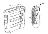
- FIGS. 2B and 2Cillustrate cartridges 150 a and 150 b that include an air filter 160 in accordance with specific embodiments of the present invention.
- FIG. 4Aillustrates a cartridge 220 that includes an air filter 160 in accordance with another embodiment of the present invention.
- Filter 160is positioned such that air leading into the fuel cell package 175 ( FIG. 2C ) first passes through the filter before entering the package.
- FIG. 2Bshows the disassembly of cartridge 150 a and the positioning of an air filter 160 included in a cartridge assembly 152 in accordance with a specific embodiment of the present invention.
- Filter 160is arranged on assembly housing 152 such that when fuel cartridge 150 a attaches or detachably couples to a fuel cell system package or a housing included a fuel cell system package 175 (see FIG. 2C ), air inlet into the package first passes through filter 160 .
- filter 160is positioned on the cartridge so as to rest adjacent to an inlet port on the fuel cell package when the cartridge and package are coupled together (see FIG. 2B or port 225 FIG. 5A ).
- a fuel cartridgemay include one or more vents 180 that receive the air before the air passes through the filter.
- a ventgenerally refers to a hole or port in a wall or other structure that permits gaseous communication between opposite sides the wall.
- vent 180permits air to enter and pass through internal spaces within the cartridge housing to an inlet side of filter 160 .
- vents 180permit air to enter cartridge housing 152 and pass through internal spaces within housing 152 to the inlet side of filter 160 through a hole 155 in housing 152 that is adjacent to where filter 160 attaches to housing 152 .
- the ventspermit the cartridge to remain relatively small but still include internal channels and volumes for airflow to service the inlet filter (particularly one that rests directly adjacent to the fuel cell package when the cartridge and package are coupled together).
- vents 180may be included in any structural member of the cartridge. In the embodiments shown in FIGS. 4B and 4C , air enters the cartridge through multiple vents 180 included in the assembly housing 152 (dashed lines are used to illustrate airflow).
- vents 180are included in the main housing 154 that surrounds a bladder. In this case, cartridge 220 also includes filter 160 set and recessed into the main housing 154 .
- Cartridges 150 and 220may or may not include an internal bladder, but generally include an internal volume with space that permits air to pass from vents 182 to the inlet side of filter 160 .
- Assembly housingmay include any number of vents to service airflow into the fuel cell package, e.g., from 1 to about 50 is suitable in many embodiments.
- the embodiment shown in FIG. 4Bincludes 25 vents (18 on the sides and 7 in the head portion of the housing assembly); the embodiment shown in FIG. 4C includes 12 (four on the sides and eight in the head portion).
- inlet air for the fuel cell systemfirst enters into the cartridge 150 through vents 180 , passes through filter 160 , and enters into package 175 via a port (not shown in FIG. 4B or 4 C) included in the package that matches the position of filter 160 when cartridge 150 and package 175 are coupled together.
- a portnot shown in FIG. 4B or 4 C
- Filter 160is thus configured to intercept and filter air before a portable fuel cell system receives the air, and removes undesirable particulates and substances from the inlet air stream.
- filter 160includes a micron or submicron particulate filter that includes one or more layers of a filter material.
- Many filtersinclude a relatively flat profile; in this case, an inlet side of the filter refers to a side of the filter that first receives incoming and unfiltered air, while an outlet side of the filter refers to a second side of the filter, opposite to the inlet side for a flat filter, from which filtered air emerges.
- the material used in filter 160is typically selected based on the undesirable particulates and substances that a system designer wants to remove from the inlet air stream. Filter cost and size may also affect selection. Particulates and substances captured by filter 160 may include any contaminant that may damage a fuel cell system or affect fuel cell system performance. For example, such contaminants include those that may damage a cathode or affect a cathode catalyst used in the fuel cell, or those that may affect a catalyst included in a reformer or burner in the fuel processor. Specific examples include: dust, dirt, smoke, sand, liquids such as water or an oil, soot particles, cordite or other explosives residue, pet dander, carpet fibers, pollen, etc.
- Filters suitable for removing any of these particulates and substancesare commercially available from a wide variety of vendors. Water, for example, could be filtered using Goretex or a similar material that blocks water while allowing air to pass through.
- One suitable air filter for capturing dustis supplied by Small Parts Inc. Part number: CMP-0297-D, (297 micron Polypropylene).
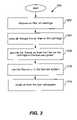
- FIG. 3illustrates a method 200 for filtering air used in a portable fuel cell system in accordance with one embodiment of the present invention.
- Method 200begins by disposing an air filter on a fuel cartridge for use with a portable fuel cell system ( 202 ).
- the air filteris added to the fuel cartridge when the fuel cartridge is initially manufactured.
- the air filteris replaced (a new filter replaces an old and used one) or refurbished when the cartridge is refilled.
- Refurbishing the filtermay include an automated process that releases trapped particulates from the filter, such as blowing high-pressure air, in an opposite direction from the direction of filtration, to release trapped particulates.
- Method 200proceeds, during fuel cartridge usage with a fuel cell system, by passing air through the air filter on the cartridge to produce filtered air ( 204 ).
- the cartridge air filterrests adjacent to a port on the fuel cell system package and a pressure source within the package provides a negative pressure to the outlet side of the filter, thereby drawing air into the inlet side of the filter, through the filter material, and out the outlet side.
- the airmay enter a portion of the cartridge housing through one or more vents arranged permit air passage through the housing into the inlet side of the filter.
- Filtered airthen passes from the outlet side of the filter on the cartridge to the fuel cell system in the portable package ( 206 ).
- airpasses into the fuel cell package and immediately travels to an air source included in the portable package (or multiple air sources).
- the air sourceis disposed along an air path between the filter and a downstream recipient of the air in the fuel cell package. In this case, the air source creates a negative pressure across the filter and draws air from the ambient room, through the filter and into the package, and may also provide a positive pressure for moving the air to the downstream recipient in the fuel cell system.
- FIGS. 5A-5Cillustrate exemplary airflow patterns that pass through an air filter 160 on a cartridge 16 and into portable fuel cell system package 11 according to various embodiments of the present invention.
- air source 224provides the filtered air to fuel cell 20 for electrochemical reaction and electrical energy production.
- Air source 224moves air (airflow is shown by dotted lines) from the ambient environment 226 , through the cartridge 16 , into and out of portable package 11 . More specifically, air source 224 applies a negative pressure and pulls air: from the ambient environment 226 , through one more vents 223 in cartridge 16 , through an internal space in the cartridge housing, through filter 160 , into a port 225 on an outer wall of package 11 .
- Air source 224then pushes air, via internal air conduit 228 , to a cathode in fuel cell 20 where some oxygen in the filtered air is used in the cathode to generate electricity and water.
- Conduit 228may include one or more straight or bent channels internal to package 11 , such as one more fixed channels in a metal wall of the fuel cell or internal wall the package housing. Conduit 228 opens to a cathode intake manifold that distributes the air and oxygen within the fuel cell. A cathode exhaust manifold then collects the used air and oxygen after chemical processing in fuel cell 20 for outlet via exhaust conduit 229 , which outlets the fuel cell exhaust into ambient environment 226 .
- filter 160is selected to remove particulates and contaminants in the ambient environment that may affect fuel cell 20 and any of its components.
- a cathode catalyst in the fuel cellinteracts with the incoming air (intentionally only the oxygen) and will benefit when filter 160 removes particulates in the air that degrade, or are harmful to, the cathode catalyst.
- Another failure mode caused by particulate ingestionis blockage of gas and liquid passages over time; for example, small gas passage could become blocked with small dust particles thereby preventing access of air to one or more cells in the fuel cell stack.
- Such particulatesinclude, for example, sand, pollen, pet or carpet fibers for example.
- One suitable air filteris supplied by Small Parts Inc. Part number: CMP-0297-D, (297 micron Polypropylene).
- Air source 224may include any pump, compressor, fan, or any other device suitable for moving air. Small fans of a desired flow rate are commercially available from a wide variety of vendors.
- a model BTC compressor as provided by Hargraves, N.C.is suitable to pressurize oxygen and air for air movement as shown in FIG. 5A .
- an air sourceincludes a larger fan 232 that moves filtered air across fuel cell 20 for cooling and thermal management.
- fan 232draws air from the ambient environment 226 , through one more vents 223 in cartridge 16 , through an internal space in the cartridge housing, through filter 160 , and into a port 225 on an outer wall of package 11 . Fan 232 then blows cooling air 230 over one or more portions of fuel cell 20 .
- fuel cell 20includes one or more heat transfer appendages 46 that permit conductive heat transfer with internal portions of a fuel cell stack.
- cooling fan 232blows cooling air at ambient room temperature, over the heat transfer appendages 46 , which permits dedicated and controllable conductive/convective cooling of internal portions of fuel cell 20 (by turning on/off fan 232 ) during electrical energy production.
- a model AD2005DX-K70 fan as provided by Adda USA of California, or part number YW03015005BM provided by Y.S. Technologies of Taiwan,are suitable for use.
- the airis outlet from package 11 using an exhaust port in the housing of package 11 .
- fan 232is positioned to blow air across fuel processor 15 for cooling of the fuel processor.
- filter 160is selected to remove particulates and contaminants in the ambient environment that a designer does not want internal to package 11 .
- Such particulatesinclude, for example, sand and small fibers.
- One suitable air filteris a FC3 filter material as provided by Donaldson Company Inc. of Minneapolis, Minn.
- an air sourcemoves filtered air into fuel processor 15 .
- fuel processor 15includes a burner 30 , a reformer 32 and a regenerator 36 .
- Burner 30uses catalytic combustion to generate heat for reformer 32 .
- burner 30receives fuel 17 from cartridge 16 and consumes the fuel in the presence of oxygen (in the filtered air) to generate heat.
- a catalyst in reformer 32reacts with the fuel 17 to produce hydrogen and carbon dioxide; this reaction is endothermic and draws heat from burner 30 , and also uses oxygen in the filtered air.
- Regenerator 36pre-heats incoming filtered air before the air enters burner 30 and reformer 32 .
- regenerator 36uses outward traveling waste heat in fuel processor 15 to increase thermal management and thermal efficiency of the fuel processor. Specifically, waste heat from heater 30 pre-heats incoming filtered air provided to reduce heat transfer to the air within the heater. As a result, more heat transfers from the burner to reformer 32 .
- Regenerator 36also functions as insulation for the fuel processor. More specifically, by reducing the overall amount of heat loss from fuel processor 15 , regenerator 36 also reduces heat loss from package 11 by dissipating it into filtered air going into the fuel processor for chemical processing (before the heat escapes the system). This reduces heat loss from fuel processor 15 , which results in a cooler fuel cell system package.
- Air source 244applies a negative pressure and pulls air: from the ambient environment 226 , through one more vents 223 in cartridge 16 , through filter 160 , and into package 11 . Air source 244 then pushes the filtered air, via internal an air conduit (not shown), to regenerator 36 where the filtered air is heated using exhaust heat generated in the fuel processor. The heated and filtered air then proceeds to the burner 30 and reformer 32 for chemical reaction in each. The used air is then exhausted from the fuel processor 15 and package 11 .
- filter 160is selected to remove particulates and contaminants in the ambient environment that may affect or poison fuel processor 15 and any of its components.
- a reformer catalystsuch as palladium interacts with the incoming air and will benefit when filter 160 removes contaminants that are harmful to the reformer catalyst.
- Such particlesinclude, for example, soot and hydrogen sulfide.
- One suitable air filteris a FC3 filter material as provided by Donaldson Company Inc. of Minneapolis, Minn.
- Including filter 160 on a disposable or reusable fuel cartridgeadvantageously allows replenishable filtering for a fuel cell system. Since most filters are limited life devices and are intended for replacement at some point, placing a filter on a disposable or reusable fuel cartridge advantageously allows a user to replace a fuel cell system filter when a replacement cartridge is swapped in, as opposed to replacing a filter on the fuel cell system package or electronics device, which may have an operational lifetime of years.
- the fuel cell system package 11includes a second filter that doubly intercepts the filtered air output from filter 160 .
- Thisprovides another layer of filtration to further reduce contaminant presence in the fuel cell system. Any of the above mentioned systems described in FIGS. 5A-5C may benefit from this secondary filtration.
- another air pathwayproceeds as follows: ambient room or space, through one or more vents, through the filter included in the cartridge, through one or more filters included in the package, to a compressor or blower, through the cathode distribution in the fuel cell such as the cathode intake manifold, collection of the used air in a cathode exhaust manifold, and out an exhaust for the fuel cell package.
- Providing airflow through one or more filters on a fuel cartridge before passage through the second filter in the fuel cell system packageallows the secondary filter to work less, which extends the operable lifetime of the second filter.
- FIG. 6shows a simplified portable fuel cartridge 300 in accordance with another embodiment of the present invention.
- Cartridge 300includes a housing 102 , filter 160 , hydrophobic filter 302 and a sensor 304 . Housing 102 will be described in further detail below.
- Hydrophobic filter 302prevents the passage of water therethrough. As shown, hydrophobic filter 302 a is placed adjacent to, and on the air inlet side, of filter 160 to prevent water from reaching filter 160 and from penetrating into a port in a fuel cell system package that receives filtered air from filter 160 . This prevents water from reaching internal portions of the package.
- a hydrophobic filter 302 bis arranged on the inner wall of housing 102 to cover vents 180 .
- Hydrophobic filter 302 bacts as a waterproof membrane that prevents water from entering cartridge 300 through vents 180 .
- hydrophobic filters 302 a and 302 bprevent water from reaching internal portions of fuel cartridge 300 .
- hydrophobic filter 302prevents liquid water from entering the fuel cartridge and/or fuel cell package (or an electronics device as the package), but allows air to pass through filter 302 .
- Hydrophobic filters suitable for use with a fuel cartridge of the present inventionare commercially available from a wide variety of vendors.
- the hydrophobic filter 302may comprise micro porous Teflon or another micro porous material such as Teflon coated paper.
- a sintered metal filterfor example one with a 3 micron pore size, may also be used.
- One suitable filter 134includes micro porous “Gore Tex” Teflon as provided by WL Gore Associates of Elkton, Md.
- a hydrophobic filter 160also prevents fuel 17 from escaping cartridge 300 housing in the event that a bladder in the cartridge develops a leak.
- filter 160is selected such that it has both hydrophobic properties and filtering properties as described above with respect to FIGS. 5A-5C .
- a fuel cartridgeincludes a sensor that detects a parameter or state pertinent to a user or the fuel cell system.
- Sensor 304is disposed along the inlet airflow to the fuel system to detect one or more properties or states of the inlet air. The property may include the concentration of a substance in the air, for example.
- sensor 304includes a carbon monoxide or other hazardous gas detector or indicator.
- a carbon monoxide sensor 304 disposed to measure carbon monoxide in the inlet air streaminforms a user or the fuel cell system when an undesirable level of carbon monoxide is in the ambient room.
- Other hazardous gases that may be detected by a sensor on cartridge 300include methanol, hydrogen, and formaldehyde, for example
- the fuel cell packageincludes an infrared or other detector that is configured to probe and read sensor 304 .
- sensor 304may include a carbon monoxide sensor that changes color the presence of a threshold carbon monoxide concentration.
- the infrared sensordetects the change in color, and informs a system controller on the portable fuel cell system package that an undesirable level of carbon monoxide has been detected.
- the fuel cell system controllermay then shut down the fuel cell system, eject the cartridge, or carry out some other reaction in response to detecting the event from sensor 304 .
- Putting one or more carbon monoxide or other hazardous gas sensor 304 on the inlet airflowthen detects concentration levels in the ambient room, as opposed to putting the sensor on the exhaust outflow (see below), which detects carbon monoxide concentration level output by the fuel cell system (which may be minute relative to the size of the ambient environment).
- Other gasesmay be monitored (and used control output of a fuel cell, for example).
- the sensorin conjunction with the control system, can infer the specified gas composition in the incoming air stream, and compare the concentration to a threshold value, which if exceeded could cause the fuel cell to shut down.
- a threshold valuewhich if exceeded could cause the fuel cell to shut down.
- IEC standard 62282-6-1 Ed.1/PASwhich governs the use and transport of portable methanol fuel cells on commercial aircraft, lists the following maximum emissions rates and concentration limits for a 1 m 3 air volume with 10 air changes per hour (see Table 1). Any of these materials or concentrations are suitable for use with a sensor of the present invention. Other concentrations may be detected by a sensor.
- the fuel cell system controlleris configured to shut down the fuel cell system when one of these parameters is detected on a cartridge sensor.
- a fuel cartridgein another disposable component embodiment, includes an exhaust filter that cleanses gaseous exhaust produced by a portable fuel cell system. Imperfect chemical processing in a fuel cell or fuel processor or other ancillary catalytic reactor such as a fuel cell startup burner or gas clean-up reactor may produce or not fully eliminate one or more unintended exhaust products, or exhaust products at unintended levels.
- FIG. 7illustrates a cartridge 400 that includes an exhaust filter 402 configured to clean and separate out one or more exhaust products included in an exhaust 409 produced by a fuel cell system in package 11 . As shown, cartridge 400 is currently coupled to package 11 .
- Exhaust filter 402is configured to intercept gaseous exhaust produced by fuel cell system package 11 . As shown in FIG. 7 , exhaust filter 402 is disposed on a wall of cartridge 400 proximate to outlet port 408 of package 11 when cartridge 400 is coupled to package 11 .
- An air source 244(as described above with respect to FIG. 5C ) draws air in from ambient environment 226 and supplies the air to a catalytic burner 30 and a reformer 32 in fuel processor 15 . Oxygen in the air is then used for chemical processing in burner 30 and reformer 32 . Each fuel processor component outputs its own exhaust to a common exhaust line for output from package 11 . Burner 30 catalytically combusts fuel and oxygen in the air to produce combustion byproducts that are output from package 11 . Incomplete combustion may produce carbon monoxide, for example. Reformer 32 catalytically processes the incoming fuel, such as a hydrocarbon fuel, to produce hydrogen and carbon dioxide. Imperfect fuel processing in reformer 32 may also produce carbon monoxide, for example.
- the undesirable exhaust products in exhaust 409may include any chemical byproducts produced by a fuel cell or fuel processor or other ancillary reactors such as a fuel cell heat-up burner or gas clean-up reactor.
- exemplary exhaust products captured by filter 402include: methanol, formaldehyde, formic acid, methyl formate, hydrogen sulfide, hydrogen, and ammonia from fuel processor 15 , and/or carbon monoxide, phosphoric acid, fluoric acid, and ammonia from fuel cell 20 .
- Other fuel cell systemsmay include other by-products, depending on the system and the fuel. For example, a butane fuel may be reformed and the exhaust filters for butane or methane.
- the filtermay detect or remove any reactant or byproduct in a fuel cell system, where the exhaust byproducts are intended or not. This also includes filtering for materials added to the fuel, such as oderrants and colorants added to the fuel, which may or may not pass through the fuel cell system.
- Exhaust filter 402is selected based on the exhaust products to be filtered out of the exhaust stream.
- Exhaust filter 402may include a scrubbing bed filled with a material, such as activated carbon, potassium permanganate, cupric chloride (CuCl 2 ) or another catalyst that reacts with the exhaust products to be cleansed.
- the catalyst or absorbentabsorbs CO, methanol vapor or H 2 S.
- one suitable carbon monoxide filteris a copper chloride particles disposed between two porous meshes, or disposed onto a porous structure such as a silica frit. If copper chloride-based materials are used, a color change will occur when the material becomes saturated with CO; this could lend itself to optical sensing and control feedback on the fuel cell system.
- One suitable formaldehyde filteris composed of 2,4-dinitrophenyl hydrazine, or high surface area activated carbon particles, disposed between two porous meshes; or disposed onto a porous structure such as a silica frit.
- Other exhaust filtersare suitable for use, for removal of a range of gasses as needed i.e., see above table of IEC regulations
- multiple exhaust filters 402may be used, where each filter removes a different byproduct from the exhaust stream.
- a first exhaust filter 402may be disposed to separate out carbon monoxide, while a second exhaust filter 402 cleans formaldehyde from the exhaust stream.
- passing hydrogen through filter 402 when the storage device 400 is refilled with fuelrejuvenates exhaust filter 402 .
- exhaust filter 402may be replaced with a filter when the storage device 400 is refilled.
- a portable fuel cartridgein another embodiment, includes one or more desiccants for lowering humidity in a fuel cell system package that is coupled to the cartridge.
- FIG. 8shows a portable fuel cartridge 450 that includes a desiccant 452 in accordance with a specific embodiment of the present invention.
- desiccant 452opens into a volume 454 internal to package 11 .
- Desiccant 452passively absorbs moisture within volume 454 , thus decreasing the humidity within volume 454 both when the fuel cell system is on and when it is inactive.
- Desiccant 452typically works over extended durations, and thus is well suited to absorb moisture over long periods of time, such as when the fuel cell is shut off between uses.
- desiccant 452acts as a passive moisture sink to absorb moisture internal to the portable fuel cell system package 11 . This prevents the moisture from collecting on components (such as 15, 20, and their constituents) within the package, particularly when the fuel cell system is not in use.
- the moisturemay come from various sources. Many portable fuel cell systems are used in environments that promote moisture aggregation internal to the fuel cell system package. For example, humid environments often leave high levels of moisture inside the portable package after the fuel cell system is turned off. A cooling fan may newly introduce humid air each time the fuel cell system is used. Moisture in the humid air then gathers on (or in) the fuel cell system components, and may damage them. For example, catalysts in a fuel processor may be damaged by inadvertent moisture aggregation internal to the fuel processor. Moisture may also come from fuel cell 20 ; moisture is often a product of the electrochemical reaction in a fuel cell, and is present in package 11 after shut down. Another moisture issue: many fuel cell systems operate at elevated temperatures; as fuel cell components cool, moisture internal to package 11 in the humid air often condenses on cooling components.
- Desiccant 452absorbs moisture internal to package 11 so as to reduce or minimize moisture collection on (or in) internal components of package 11 . Desiccant 452 even absorbs moisture after the fuel cell system has been shut down, which may draw out moisture in package 11 .
- Desiccant 452is in gaseous and moisture communication with internal volume 454 .
- desiccant 452is disposed on cartridge 450 such that when the cartridge mechanically couples to package 11 , desiccant 452 is proximate to vent 456 .
- Vent 456permits gaseous and moisture communication between desiccant 452 and internal volume 454 .
- vent 456may include any hole or port in a wall or other structure that air or moisture can travel through. In this case, vent 456 permits gaseous communication between internal volume 454 and outside package 11 .
- Desiccant 452may include one or more commercially available moisture absorption materials or products. For example, numerous vendors provide commercially available sacs that allow air to pass therethrough and include small desiccants beads in the sacs. Multiple sacs may be used to increase desiccant absorption, while using inexpensive and commercially available products.
- One suitable desiccantis Drierite 97% CaSO 4 , 3% CoCl 2 beads supplied by W.A. HAMMOND DRIERITE CO. LTD., Xenia, Ohio.
- desiccant beadsare disposed on a gaseous filter such as that described above with respect to filter 160 ( FIG. 2B ).
- a gaseous filtersuch as that described above with respect to filter 160 ( FIG. 2B ).
- silica beadsmay be attached onto filter 160 .
- the same vent that is used to communicate air with filter 160is also used for moisture control within package 11 .
- the desiccant beadsare sandwiched and trapped between filter layers in a multiple layer filter 160 .
- desiccants 452offers a renewable and replenishable source of moisture absorption/control each time a fuel cartridge is replaced for portable fuel cell system. This reduces resources on the fuel cell system needed for moisture control.
- the fuel cartridgeis shipped and stored in a vapor barrier such as a commercially available vacuum pack that prevents desiccant usage and exhaustion before initial usage of the fuel cartridge with a fuel cell system package.
- a cartridge of the present inventionmay also include an absorbent such as a small sponge or swab, located on or near a fuel connector, to collect any fuel leakage during device connection or disconnection.
- FIG. 9shows a portable fuel cartridge 500 that includes an absorbent 502 in accordance with a specific embodiment of the present invention.
- Absorbent 502attaches to a wall in cartridge assembly housing 152 , proximate to fuel connector 158 . Absorbent 502 is thus positioned to soak up fuel misplaced between cartridge 500 and a fuel cell system package.
- fuelmay leak during connection and disconnection between cartridge 500 and package 175 ( FIG. 2C ).
- fuelmay escape from fuel connector 158 during rough handling.
- absorbent 502The fuel absorbing capacity of absorbent 502 will depend on the size and material of absorbent 502 .
- absorbent 502is sized small enough to not interfere with connection between cartridge 500 and a fuel cell system package, but large enough to absorb small amounts of fuel that may escape from the intended fuel line.
- Absorbent 502may include any material suitable for absorbing a fuel. An inexpensive absorbent is small piece of a commercially available sponge. Absorbent 502 may also be selected based on a specific fuel used in the fuel cell system.
- absorbent 502is replenished each time a new cartridge is used. This simplifies a fuel cell system package by removing a need for similar functionality at the mating connector on the fuel cell system package.
- the fuelincludes a colorant and absorbent 502 stains when it soaks the fuel.
- a sponge with a neutral or soft coloris suitable for use in this regard. Suitable colorants are described in further detail below.
- cartridge 16stores a fuel 17 .
- cartridge 16includes a bladder 100 , housing 102 and connector 104 .
- Bladder 100contains fuel 17 and conforms to the volume of fuel in the bladder.
- Compliant walls 101 of bladder 100which expand and/or open when fluid is added to bladder 100 , form the volume and contract and/or collapse when fluid is removed according to the negative pressure developed upon fluid removal.
- bladder 100includes a sac that changes size and shape with the volume of liquid contained therein.
- Plastic, rubber and latexare suitable materials for use as the walls 101 of bladder 100 .
- the wallsare compliant and change size with a changing liquid volume, and in some cases the walls allow for stretching with high fluid pressures in bladder 100 .
- Walls 101may also comprise a fire retardant material.
- bladder 100comprises a fixed cylinder and a piston that is pushed by a spring and moves in the cylinder to pressurize the bladder and displace volume according to used fuel.
- a maximum volume 119characterizes bladder 100 when the bladder fully expands.
- Maximum bladder volumesmay vary with an application.
- maximum volumes for cartridge 16range from about 20 milliliters to about 4 liters. Maximum volumes from about 20 milliliters to about 800 milliliters are suitable for many portable electronics applications.
- a maximum volume for bladder 100 of about 200 to about 500 millilitersis suitable for laptop computer usage and many portable applications.
- the maximum volume for bladder 100may differ from the fuel capacity of cartridge 16 , e.g., it includes multiple bladders.
- some applicationsmay require the use of a fuel cartridge & bladder, which is sized to offer several weeks or more of run time. Such a cartridge could have 10-20 L of fuel.
- a cartridge of the present inventionmay contain other systems for storing a fuel.
- a cartridge of the present inventionmay include any volume internal to a housing for sized to store a fuel.
- a cartridgemay include a sealed internal compartment or volume that stores a fuel and a spring that pushes on a moveable wall for the compartment (and no bladder); as the fuel is consumed, the spring passively changes internal volume.
- Another suitable fuel storage designincludes one or more chambers located within the rigid housing; one may be used as the primary fuel storage, and a second used as a receptacle for waste by-products, such as sodium borate or sodium carbonate for example, which must be disposed of when the cartridge is disposed of or recycled.
- two or more bladdersmay be used as primary fuel storage, such as for example, water and diesel fuel or aluminum powers and water, which must be mixed together in order for the fuel cell system to generate power, but which are not miscible with each other or which cannot be safely stored in the same cavity.
- Another suitable fuel storage designincludes a wick that draws fuel from an internal cavity of fixed dimensions.
- the cartridge bladdermay be pressurized, either by a pressure source on the fuel cell, such as the air compressor for example, or by means of a propellant; the pressure source being applied in the space between the bladder and the outer wall.
- a propellantsuch as dimethyl-ether (DME) may be mixed into the fuel mixture.
- DMEdimethyl-ether
- 5-30% DME mixed with a 67% (volume) mixture of methanol and watermay be used as means of applying pressure internal to the bladder; the resulting mixture can then be fed into the fuel system.
- fuel storage configurations that do not include a bladderare also suitable for use herein.
- Housing 102provides mechanical protection for fuel 17 , bladder 100 and any other components of storage device 16 included within housing 102 .
- Housing 102comprises a set of rigid walls 110 that contain bladder 100 and other internal components of cartridge 16 .
- Walls 110collectively form an outer case or shell that mechanically separates components internal to housing 102 from the external environment.
- Walls 110also collectively form an interior cavity 112 .
- Interior cavity 112is a space within storage device that contains fuel 17 and bladder 100 .
- Interior cavity 112may comprises multiple compartments, each of which includes its own fuel storage (e.g., a separate bladder).
- Housing 102is referred to herein as a ‘housing assembly’ when one or more rigid walls or parts are added to cartridge 16 and provide additional functionality other than just containment of internal components.
- Such functionalitymay include connectivity with a package (e.g., a sliding interface for mating with a sliding interface on a fuel cell package), filtration of air going into a fuel cell system package as described above, and holding one or more components of the cartridge such as a chip.
- Rigid walls 110may comprise a suitably stiff material such as a plastic, metal (e.g., aluminum), polycarbonate, polypropelene, carbon fiber matrix, carbon composite material, etc. Rigid walls 110 may also be formed from a fire retardant material such as a fire retardant plastic material.
- a fire retardant materialsuch as a fire retardant plastic material.
- One suitable fire retardant plastic material for walls 110is 8-12% weight, JLS-MC mixed with PA66 Polyamide as provided by JLS Chemical of Pomona, Calif.
- Rigid walls 110may be designed according to criteria for construction of thin walled pressure vessels. In this case, walls 110 and housing 102 may be designed to withstand a maximum pressure within bladder 100 .
- Housing 102may be variably shaped as desired by an application and the present invention is not limited to any particular shape.
- housing 102includes an elliptical (including circular) cross section, a rectangular cross section with chamfered corners, or other substantially consistent profile or shape in a given direction.
- housing 102includes a) a top cap 109 that holds connector 104 and b) a substantially consistent cross section in a direction that extends away from the top cap.
- Connector 104interfaces with a mating connector 140 included in device 11 ( FIG. 1 ).
- Mating connector 140may be disposed on a variety of devices. In one embodiment, mating connector 140 is disposed on a side portion of an OEM device (i.e. a laptop computer). In another embodiment, mating connector 140 is included in a portable fuel cell package. Mating connector 140 may also be included in refilling hardware that refills cartridge 16 with fuel source 17 .
- connector 104 and mating connector 140permit transfer of fuel source 17 between bladder 100 and the external device 11 .
- mating connector 140When mating connector 140 is included in a device that includes fuel processor 15 ( FIG. 1 ), connector 104 and mating connector 140 interface to permit transfer of fuel 17 from cartridge 16 to fuel processor 15 , and through any intermediate plumbing between the two.
- connector 104 and mating connector 140interface to permit transfer of fuel 17 from the refiner to cartridge 16 .
- Interface between connector 104 and mating connector 140may comprise any relationship and mating structures that permit fluid communication between the two connectors. Several contact valves and configurations are provided below.
- a pump in device 11 and run by a fuel cell system controllerdraws fuel 17 into device 11 . More specifically, fuel 17 travels from bladder 100 , through tube 107 and connector 104 , into and through mating connector 140 , and through tube 111 in device 11 to a fuel processor 15 included therein.
- connector 104 or mating connector 140includes a contact valve, which when depressed, permits fuel flow between the device and cartridge.
- the connectoronly opens when contacting the other while cartridge 16 interfaces with device 11 . This provides contact shutoff capability when cartridge 16 is removed.
- Dual contact valve designsare also permissible in which both contact valves must be depressed before fuel flows.
- Cartridge 16 and device 11 , and or connector 104 and mating connector 140may also include detachable mechanical coupling to selectively secure the interface, such as sliding interfaces and latching elements that bind connector 104 and mating connector 140 together until physically released.
- connector 104incorporates a quick disconnect that permits cartridge 16 to be readily removed by pulling on housing 102 (or the assembly housing). This separates connector 104 and mating connector 140 and separates any electrical links and detaches plumbing responsible for fluid communication between cartridge 16 and device 11 . A second cartridge 16 with a quick disconnect connector 104 may then be readily inserted back into mating connector 140 . The quick disconnect allows rapid replacement of cartridge 16 with another cartridge 16 when fuel source volume levels are low. Further description of cartridge connectors suitable for use with the present invention are described in commonly owned and co-pending patent application Ser. No. 11/316,216, which is incorporated by reference herein in its entirely for all purposes.
- Cartridge 16may also includes one or more vents in housing 102 that allow air to enter and exit as a bladder 100 changes in volume.
- the air ventcomprises one or more holes or apertures in a wall of housing 102 .
- bladder 100collapses and creates a negative pressure in internal cavity 112 outside of bladder 100 . Based on this negative pressure caused by a decreasing volume of bladder 100 (or increasing volume of internal cavity 112 outside bladder 100 ), air enters through the air vent into internal cavity 112 and displaces the decreasing volume of bladder 100 .
- positive pressure caused by an increasing volume of fuel 17 in bladder 100causes air to exit through the vent.
- cartridge 16does not include a vent in the cartridge housing 102 and relies on a vent included in a valve or connector 104 that provides fuel source communication into or out of the storage device.
- a filtermay span the cross section of the vent and intercepts air passing through the vent.
- FIG. 2Billustrates an exploded perspective view of a cartridge 150 a in accordance with a specific embodiment of the present invention.
- FIG. 2Cillustrates a cartridge 150 b mechanically coupled to an exemplary portable fuel cell package 175 . Either cartridge 150 may detachably couple to package 175 .
- Portable package 175typically contains a portable fuel cell system, and includes a housing that holds and protects the fuel cell system components.
- the housingmay also include latching and connection features for mechanical coupling to a cartridge.
- the portable packagerefers to a package that includes a fuel cell system and weighs less than ten kilograms. Further description of a portable fuel cell system packages is described in commonly owned and co-pending patent application Ser. No. 11/120,643, which is incorporated by reference herein in its entirety for all purposes.
- cartridge 150includes a fluid transfer valve 156 , a connection valve 158 , an assembly housing 152 , a main housing 154 , one or more filters 160 , mechanical interface components such as a slide interface 162 , and a digital chip 164 .
- Filter 160was described above.
- Housing assembly 152attaches to main housing 154 .
- Housing assembly 152attaches to main housing 154 ; both housing portions provide mechanical protection for other components of cartridge 150 .
- Housing assembly 152also permits connectivity with a fuel cell device, supports and locates various components included in cartridge 150 , and adds structural integrity to cartridge 150 .
- Housing assembly 152may include a molded and rigid plastic, for example.
- housing assembly 152surrounds main housing 154 and provides mechanical protection for main housing 154 .
- assembly housing 152only partially surrounds main housing 154 and main housing 154 includes its own walls that contain and mechanically protect an internal bladder and fuel.
- main housing 154is substantially cylindrical. Other geometries for assembly housing 152 and main housing 154 may be used.
- Housing assembly 152includes one or more mechanical interface components that allow detachable coupling to a fuel cell package). As shown, assembly housing 152 includes a slide interface 162 that interfaces with a mating groove on fuel cell package 175 . To couple cartridge 150 and package 175 , slide interface 162 slides vertically (from the bottom) into a mating groove on the fuel cell package 175 . The sliding interface permits a sliding relationship between the cartridge 150 and package 175 .
- a latching interfacemay be included to lock and hold cartridge 150 in one or more positions relative to package 175 along the sliding interface.
- the latching interfacelets a user know (e.g. acoustically and kinesthetically) when the two are coupled together or at some desired position relative to each other.
- Fluid transfer valve 156opens to the inner bladder and permits fluidic communication with the bladder. As shown, fluid transfer valve 156 is disposed at one end of the cylindrical main housing 154 . In one embodiment, fluid transfer valve 156 is a contact valve, which when depressed, permits flow of fuel from cartridge 150 ; and when not depressed, the contact valve prevents the flow of fuel from the cartridge. As shown, contact valve 156 outputs the fuel at about a 90-degree angle relative to fluid communication with a bladder included in main housing 154 . In another embodiment, fluid transfer valve 156 outputs the fuel in an upward direction. Contact valves suitable for use with the present invention are available from a wide variety of vendors. Suitable commercially available valves are used in aerosol and shaving products, for example, and many are well suited for use herein.
- fluid transfer valve 156provides the fuel to a line 165 internal to assembly housing 152 that communicates the fuel to a connection valve 158 .
- the connection valve 158acts as a connector for cartridge 150 and interfaces with a downward facing mating connector on package 175 .
- connection valve 158permits transfer of fuel between cartridge 150 and package 175 .
- connection valve 158communicates the fuel from line 165 to a mating connector and fuel line in package 175 .
- the mating connectormay be disposed on the fuel cell package 175 , or another device such as a fuel cell, or a portion of an electronics device such as a laptop computer.
- the cartridge assemblyuses a commercially available contact valve or connection valve 158 .
- a suitable connection valvethat permits high pressure and uses contact to open and close fluid communication is a Schrader valve.
- Suitable commercially available Schrader valvesare available from a wide variety of vendors. Other valves may be used.
- connection valve 158is shown pointing upwards, other orientations are possible.
- Cartridges of the present inventionmay include one or more commercially available components. Using commercially available products allows the present invention to use mass produced, readily available, and proven technology. Off-the-shelf components may also reduce cost for a cartridge.
- Aerosol cansare a proven technology suitable for use with housing 102 to store a hydrogen bearing fuel.
- Conventional aerosol containersalso include a relatively high evacuation efficiency and may rely on commercially automated filling equipment.
- Other commercially available components suitable for use in a hydrogen fuel cartridgeinclude those used in the shaving industry, those use in portable lighters, and those used for pressurized air and/or fuel delivery (e.g., to power a nail gun).
- These devicesoften include commercially available components suitable for use in a cartridge of the present invention such as: commercially available cartridge housings (also referred to as ‘canisters’ or ‘cans’), bladders, commercially available heads (or ‘mounting caps’) that attach to the canisters, nozzles, and so on.
- Many commercially available nozzlesinclude contact valves that permit binary fluid communication with/without contact.
- One suitable supplier of aerosol products including canisters and contact nozzlesis Precision Valve, Inc. of Yonkers, N.Y.
- the cartridge housingincludes commercially available aluminum components that crimp and seal together.
- the housingmay include a top aluminum head portion (also referred to as a ‘mounting cup’) that crimps to a cylindrical aluminum housing (also referred to as a ‘can’). This advantageously seals the head to the cartridge housing.
- One or more componentsmay be added internally to the aluminum cartridge housing before the seal is made.
- a bladdermay be added before the two parts are joined. The crimped connection then secures and seals the bladder.
- a cartridgemay also comprise one or more of the following materials: polycarbonate, ABS, PET, HDPE, or PCABS for housing 152 ; steel or aluminum or another suitably rigid metal or material for housing 154 ; tinplate/polypropylene/nylon for valve 156 ; and nylon or polypropylene for the bladder. Other materials may be used.
- the fuel cartridgemay also include a commercially available 202 bag accessed using a commercially available aerosol valve.
- One of skill in the artis aware of the wide range of the aerosol can designs, bags and valves, and the fuel cartridge is not limited to any particular design.
- cartridge 150includes a memory 164 , which stores information relevant to usage of cartridge 150 .
- Memory 164may comprise a mechanical, electrical and/or digital mechanism for information storage.
- memory 164includes a digital memory source that permits a controller to read and write from the digital memory.
- cartridge 150includes electrical connectivity for digital communication between memory 164 and a processor or controller on device 11 .
- Cartridge 150is considered ‘smart’ when memory 164 stores information related to the performance, status and abilities of cartridge 150 .
- a digital memory or chipallows an external controller or logic to read and write information relevant to usage of the cartridge 150 to memory 164 . Reading from digital memory 106 allows reception and assessment of information in memory 106 to improve usage of cartridge 150 . For example, a computer that receives storage device 150 may inform a user that the cartridge 150 is empty or how much fuel is left (or how much time on the system is available based on its power consumption and the amount of fuel remaining). Writing to a digital memory 164 allows information in the memory to be updated according to storage device 150 usage.
- Cartridge 16 bmay also include other features such as a pressure relief valve that limits pressure in the bladder or cartridge, a fuel filter that intercepts fuel 17 as it leaves bladder 100 and before it leaves connector 104 , a fire retardant foam disposed in bladder 100 , and a wireless identification (ID) tag for memory 164 , for example.
- IDwireless identification
- housing 102comprises a viewing window that is configured to permit a user to see a current fuel level inside a fuel cartridge.
- FIG. 10shows a cartridge 550 that includes a viewing window 552 in accordance with a specific embodiment of the present invention.
- Viewing window 552includes a transparent section or clear window in housing 154 that enables visual fuel gauging. Thus, a user may look through viewing window 552 and see the amount of fuel left in cartridge 550 .
- Viewing window 552includes a rigid and transparent polymer 554 disposed over a cut out, hole or aperture and housing 154 .
- a colorantmay be added to the fuel to provide visual stimulus.
- Suitable colorants 154include acid blue 9 at 1 ppm, table 5-4 food dye, and bright green/blue erioglaicine disodium salt as provided by Dudley Chemical Corp of Lakewood, N.J.
- the colorantalso informs a person that the fuel 17 has leaked or escaped via a path other than the desired fuel path (e.g., colored fuel may be absorbed by absorbent 502 from FIG. 9 , which then stains the absorbent material).
- adding disposable components to a fuel cartridge as described hereinimproves performance for portable fuel cell system packages. Swapping in a new cartridge when fuel is replenished also refreshes any disposable components included on that cartridge.
- the present inventionalso enables various business models for fuel cartridge sales and distribution.
- a basic fuel cartridgemay be sold with no added disposable components.
- An advanced fuel cartridgemay include one or more disposable components. This permits product variability and pricing striation, and provides a consumer with fuel cartridge choice.
- a fuel cell system included in a laptop computermay require a first fuel cartridge
- a portable fuel cell system package used by the militaryemploys a second fuel cartridge, where the disposable components included on the first and second fuel cartridges vary based on their intended and corresponding fuel cell system.
- FIG. 11illustrates a schematic operation for a fuel cell system 10 in accordance with a specific embodiment of the present invention.
- Fuel cartridge 16stores methanol or a methanol mixture as a hydrogen fuel 17 .
- An outlet of cartridge 16includes a connector 23 that mates with a mating connector on a package 11 .
- the package 11includes the fuel cell 20 , fuel processor 15 , and all other balance-of-plant components except the cartridge 16 .
- the connector 23 and mating connectorform a quick connect/disconnect for easy replacement of cartridges 16 .
- the mating connectorcommunicates methanol 17 into hydrogen fuel line 25 , which is internal to package 11 in this case.
- Line 25divides into two lines: a first line 27 that transports methanol 17 to a heater/heater 30 for fuel processor 15 and a second line 29 that transports methanol 17 for a reformer 32 in fuel processor 15 .
- Lines 25 , 27 and 29may comprise channels disposed in the fuel processor (e.g., channels in metals components) and/or tubes leading thereto.
- Flow controlis provided on each line 27 and 29 .
- Separate pumps 21 a and 21 bare provided for lines 27 and 29 , respectively, to pressurize each line separately and transfer methanol at independent rates, if desired.
- a model 030SP-S6112 pump as provided by Biochem, N.J.is suitable to transmit liquid methanol on either line in a specific embodiment.
- a diaphragm or piezoelectric pumpis also suitable for use with system 10 .
- a flow restrictionmay also provided on each line 27 and 29 to facilitate sensor feedback and flow rate control.
- each pump 21responds to control signals from the processor and moves a desired amount of methanol 17 from storage device 16 to heater 30 and reformer 32 on each line 27 and 29 .
- line 29runs inlet methanol 17 across or through a heat exchanger ( FIGS. 10A-10C ) that receives heat from the exhaust of the heater 30 in fuel processor 15 . This increases thermal efficiency for system 10 by preheating the incoming fuel (to reduce heating of the fuel in heater 30 ) and recuperates heat that would otherwise be expended from the system.
- Air source 41delivers oxygen and air from the ambient room through line 31 to the cathode in fuel cell 20 , where some oxygen is used in the cathode to generate electricity.
- Air source 41may include a pump, fan, blower or compressor, for example. High operating temperatures in fuel cell 20 also heat the oxygen and air.
- the heated oxygen and airis then transmitted from the fuel cell via line 33 to a regenerator 36 (also referred to herein as a ‘dewar’) of fuel processor 15 , where the air is additionally heated (by the heater, while in the dewar) before entering heater 30 .
- a regenerator 36also referred to herein as a ‘dewar’
- This double pre-heatingincreases efficiency of the fuel cell system 10 by a) reducing heat lost to reactants in heater 30 (such as fresh oxygen that would otherwise be near room temperature when combusted in the heater), and b) cooling the fuel cell during energy production.
- a model BTC compressoras provided by Hargraves, N.C. is suitable to pressurize oxygen and air for fuel cell system 10 .
- a fan 37blows cooling air (e.g., from the ambient room) over fuel cell 20 .
- Fan 37may be suitably sized to move air as desired by heating requirements of the fuel cell; and many vendors known to those of skill in the art provide fans suitable for use with package 10 .
- Fuel processor 15receives methanol 17 and outputs hydrogen.
- Fuel processor 15comprises heater 30 , reformer 32 , boiler 34 and regenerator 36 .
- Heater 30(also referred to herein as a burner when it uses catalytic combustion to generate heat) includes an inlet that receives methanol 17 from line 27 .
- the burnerincludes a catalyst that helps generate heat from methanol.
- heater 30also includes its own boiler to preheat fuel for the heater.
- Boiler 34includes a boiler chamber having an inlet that receives methanol 17 from line 29 .
- the boiler chamberis configured to receive heat from heater 30 , via heat conduction through walls in monolithic structure 100 between the boiler 34 and heater 30 , and use the heat to boil the methanol passing through the boiler chamber.
- the structure of boiler 34permits heat produced in heater 30 to heat methanol 17 in boiler 34 before reformer 32 receives the methanol 17 .
- the boiler chamberis sized to boil methanol before receipt by reformer 32 .
- Boiler 34includes an outlet that provides heated methanol 17 to reformer 32 .
- Reformer 32includes an inlet that receives heated methanol 17 from boiler 34 .
- a catalyst in reformer 32reacts with the methanol 17 to produce hydrogen and carbon dioxide; this reaction is endothermic and draws heat from heater 30 .
- a hydrogen outlet of reformer 32outputs hydrogen to line 39 .
- fuel processor 15also includes a preferential oxidizer that intercepts reformer 32 hydrogen exhaust and decreases the amount of carbon monoxide in the exhaust.
- the preferential oxidizeremploys oxygen from an air inlet to the preferential oxidizer and a catalyst, such as ruthenium that is preferential to carbon monoxide over hydrogen.
- Regenerator 36pre-heats incoming air before the air enters heater 30 .
- regenerator 36uses outward traveling waste heat in fuel processor 15 to increase thermal management and thermal efficiency of the fuel processor. Specifically, waste heat from heater 30 pre-heats incoming air provided to heater 30 to reduce heat transfer to the air within the heater. As a result, more heat transfers from the heater to reformer 32 .
- the regeneratoralso functions as insulation for the fuel processor. More specifically, by reducing the overall amount of heat loss from the fuel processor, regenerator 36 also reduces heat loss from package 10 by heating air before the heat escapes fuel processor 15 . This reduces heat loss from fuel processor 15 , which enables cooler fuel cell system 10 packages.
- Line 39transports hydrogen (or ‘reformate’) from fuel processor 15 to fuel cell 20 .
- gaseous delivery lines 33 , 35 and 39include channels in a metal interconnect that couples to both fuel processor 15 and fuel cell 20 .
- a hydrogen flow sensor(not shown) may also be added on line 39 to detect and communicate the amount of hydrogen being delivered to fuel cell 20 .
- fuel processor 15regulates hydrogen gas provision to fuel cell 20 .
- Fuel cell 20includes a hydrogen inlet port that receives hydrogen from line 39 and includes a hydrogen intake manifold that delivers the gas to one or more bi-polar plates and their hydrogen distribution channels.
- An oxygen inlet port of fuel cell 20receives oxygen from line 31 ; an oxygen intake manifold receives the oxygen from the port and delivers the oxygen to one or more bi-polar plates and their oxygen distribution channels.
- a cathode exhaust manifoldcollects gases from the oxygen distribution channels and delivers them to a cathode exhaust port and line 33 , or to the ambient room.
- An anode exhaust manifold 38collects gases from the hydrogen distribution channels, and in one embodiment, delivers the gases to the ambient room.
- the anode exhaustis transferred back to fuel processor 15 .
- system 10comprises plumbing 38 that transports unused hydrogen from the anode exhaust to heater 30 .
- heater 30includes two inlets: an inlet configured to receive fuel 17 and an inlet configured to receive hydrogen from line 38 .
- gaseous delivery in line 38 back to fuel processor 15relies on pressure at the exhaust of the anode gas distribution channels, e.g., in the anode exhaust manifold.
- an anode recycling pump or fanis added to line 38 to pressurize the line and return unused hydrogen back to fuel processor 15 .
- fuel cell 20includes one or more heat transfer appendages 46 that permit conductive heat transfer with internal portions of a fuel cell stack.
- heat transfer appendage 46is integral with the substrate material in the bi-polar plate. Integral in this sense refers to material continuity between appendage 46 and bi-polar plate.
- An integrally formed appendage 46may be formed with bi-polar plate in a single molding, stamping, machining or MEMs process of a single metal sheet, for example. Integrally forming appendage 46 and bi-polar plate permits conductive thermal communication and heat transfer between inner portions of bi-polar plate and the heat transfer appendage 46 via the substrate in the bi-polar plate.
- exhaust of heater 30 in fuel processor 15is transported to the one or more heat transfer appendages 46 in fuel cell 20 during system start-up to expedite reaching initial elevated operating temperatures in the fuel cell 20 .
- the heatmay come from hot exhaust gases or unburned fuel in the exhaust, which then interacts with a catalyst disposed in proximity to a heat transfer appendage 46 .
- an additional fan 37blows cooling air over the one or more heat transfer appendages 46 , which provides dedicated and controllable cooling of the stack during electrical energy production.
- Recuperator 902transfers heat from fuel cell system 10 to the inlet fuel 17 before the methanol reaches fuel processor 15 . While system 10 shows recuperator 902 heating methanol in line 29 that carries fuel 17 to the boiler 34 and reformer 32 , it is understood that recuperator 902 may be used to heat methanol in line 27 that carries fuel 17 to the burner 30 .
- recuperator 902may include any device for transferring heat produced in fuel cell system 10 or a heated gas produced in fuel cell system 10 to the incoming fuel 17 .
- Recuperator 902may include one or more heat transfer channels for moving the incoming fuel 17 , moving the heating medium, and one or more surfaces or structures for transferring heat from the heating medium to the incoming fuel 17 .
- recuperator 902includes a commercially available heat exchanger. Recuperator 902 may rely on conductive heat transfer, convective heat transfer, and combinations thereof.
- the heat used to warm fuel 17comes from a fluid in fuel cell system 10 .
- Fluids (a gas or liquid) suitable for use in this mannerinclude: the cathode exhaust from fuel cell 20 in line 33 , the reformer 32 exhaust from fuel processor 15 , the burner 34 exhaust from fuel processor 15 in line 35 , the anode exhaust from fuel cell 20 in line 38 , or combinations thereof.
- Fuel cell 20 and fuel processor 15both run at elevated temperatures during steady-state operation. Any fluids emitted from fuel cell 20 and fuel processor 15 will also be at elevated temperatures and are suitable for heat transfer to the incoming fuel.
- incoming fuel to a reformer 32 in fuel processor 15is vaporized before processing by a reforming catalyst in the fuel processor.
- incoming methanol to burner 30is vaporized before meeting the burner catalyst.
- the fuel 17typically enters the fuel cell package at its storage temperature in storage device 16 , which is normally cooler than the operating temperatures of fuel cell 20 and fuel processor 15 , or fluids emitted from these devices. Any heat transferred to fuel 17 before vaporization in fuel processor 15 reduces the amount of energy that the heater in fuel processor 15 supplies to the fuel 17 . This increases efficiency by i) leaving more heat for the reformer and catalytic production of hydrogen and/or ii) consuming less fuel to heat fuel processor 15 . This also reduces the burner exhaust temperature leaving the package. For an electrical heater that vaporizes the incoming methanol, this reduces electrical energy used by the electrical heater to vaporize the incoming fuel.
- system 10may also include other elements such as electronic controls, additional pumps and valves, added system sensors, manifolds, heat exchangers and electrical interconnects useful for carrying out functionality of a fuel cell system 10 that are known to one of skill in the art and omitted for sake of brevity.
- FIG. 11shows one specific plumbing arrangement for a fuel cell system; other plumbing arrangements are suitable for use herein.
- the heat transfer appendages 46 , a heat exchanger and dewar 36need not be included.
- Other alterations to system 10are permissible, as one of skill in the art will appreciate.
Landscapes
- Life Sciences & Earth Sciences (AREA)
- Engineering & Computer Science (AREA)
- Manufacturing & Machinery (AREA)
- Sustainable Development (AREA)
- Sustainable Energy (AREA)
- Chemical & Material Sciences (AREA)
- Chemical Kinetics & Catalysis (AREA)
- Electrochemistry (AREA)
- General Chemical & Material Sciences (AREA)
- Fuel Cell (AREA)
Abstract
Description
| TABLE 1 |
| IEC Standard 62282-6-1 Ed.1/PAS Emissions. |
| Concentration | Emission Rate | ||
| Limit | Limit | ||
| Water | Unlimited | No limit |
| Methanol | 260 | mg/m3 | 2600 | mg/hour | ||
| Formaldehyde | 0.1 | mg/m3 | 0.6 | mg/ | ||
| CO | ||||||
| 29 | mg/m3 | 290 | mg/hour | |||
| CO2 | 9 | g/m3 | 60000 | mg/hour | ||
| Formic Acid | 9 | mg/m3 | 90 | mg/hour | ||
| Methyl Formate | 245 | mg/m3 | 2450 | mg/hour | ||
Claims (32)
Priority Applications (1)
| Application Number | Priority Date | Filing Date | Title |
|---|---|---|---|
| US11/416,785US7648792B2 (en) | 2004-06-25 | 2006-05-02 | Disposable component on a fuel cartridge and for use with a portable fuel cell system |
Applications Claiming Priority (4)
| Application Number | Priority Date | Filing Date | Title |
|---|---|---|---|
| US10/877,766US20050008908A1 (en) | 2003-06-27 | 2004-06-25 | Portable fuel cartridge for fuel cells |
| US67742405P | 2005-05-02 | 2005-05-02 | |
| US68259805P | 2005-05-18 | 2005-05-18 | |
| US11/416,785US7648792B2 (en) | 2004-06-25 | 2006-05-02 | Disposable component on a fuel cartridge and for use with a portable fuel cell system |
Related Parent Applications (1)
| Application Number | Title | Priority Date | Filing Date |
|---|---|---|---|
| US10/877,766Continuation-In-PartUS20050008908A1 (en) | 2003-06-27 | 2004-06-25 | Portable fuel cartridge for fuel cells |
Publications (2)
| Publication Number | Publication Date |
|---|---|
| US20060257707A1 US20060257707A1 (en) | 2006-11-16 |
| US7648792B2true US7648792B2 (en) | 2010-01-19 |
Family
ID=37419488
Family Applications (1)
| Application Number | Title | Priority Date | Filing Date |
|---|---|---|---|
| US11/416,785Expired - LifetimeUS7648792B2 (en) | 2004-06-25 | 2006-05-02 | Disposable component on a fuel cartridge and for use with a portable fuel cell system |
Country Status (1)
| Country | Link |
|---|---|
| US (1) | US7648792B2 (en) |
Cited By (28)
| Publication number | Priority date | Publication date | Assignee | Title |
|---|---|---|---|---|
| US20080157918A1 (en)* | 2006-12-29 | 2008-07-03 | Motorola, Inc. | System for validating refillable fuel cartridges |
| US20090197150A1 (en)* | 2006-06-02 | 2009-08-06 | Toyo Seikan Kaisha, Ltd. | Fuel cell cartridge |
| US20100081017A1 (en)* | 2008-10-01 | 2010-04-01 | Angstrom Power Incorporated | Multifunctional fuel system and related methods |
| US20100239955A1 (en)* | 2007-11-09 | 2010-09-23 | Panasonic Corporation | Fuel supply system |
| US20100319331A1 (en)* | 2009-01-16 | 2010-12-23 | Wagner Wayne M | Diesel Particulate Filter Regeneration System Including Shore Station |
| US20110104021A1 (en)* | 2009-11-03 | 2011-05-05 | Societe Bic | Hydrogen Membrane Separator |
| US20110212374A1 (en)* | 2008-11-03 | 2011-09-01 | Societe Bic | Hydrogen-Generating Fuel Cell Cartridges |
| US20110229799A1 (en)* | 2010-03-17 | 2011-09-22 | Gm Global Technology Operations, Inc. | Pem fuel cell stack hydrogen distribution insert |
| US20120135335A1 (en)* | 2003-07-29 | 2012-05-31 | Societe Bic | Fuel Cartridge with Flexible Liner |
| US8769938B2 (en) | 2006-06-19 | 2014-07-08 | Donaldson Company, Inc. | Exhaust treatment device with electric regeneration system |
| US9112199B2 (en) | 2011-02-04 | 2015-08-18 | Raytheon Company | Fuel cell system and method |
| US9160022B2 (en) | 2011-03-22 | 2015-10-13 | Raytheon Company | Systems and methods providing a wearable power generator |
| US9328969B2 (en) | 2011-10-07 | 2016-05-03 | Outset Medical, Inc. | Heat exchange fluid purification for dialysis system |
| WO2016076885A1 (en)* | 2014-11-14 | 2016-05-19 | Volvo Truck Corporation | Cartridge for mixing dme fuel with additives |
| US9402945B2 (en) | 2014-04-29 | 2016-08-02 | Outset Medical, Inc. | Dialysis system and methods |
| US9545469B2 (en) | 2009-12-05 | 2017-01-17 | Outset Medical, Inc. | Dialysis system with ultrafiltration control |
| US9722268B2 (en) | 2008-11-03 | 2017-08-01 | Intelligent Energy Limited | Gas generator with starter mechanism and catalyst shield |
| US10259700B2 (en)* | 2017-03-05 | 2019-04-16 | Motion Pro, Inc | Volatile liquids refueling apparatus |
| US10305070B2 (en) | 2015-07-14 | 2019-05-28 | Johnson Controls Technology Company | Textured lead-acid battery housing |
| US11534537B2 (en) | 2016-08-19 | 2022-12-27 | Outset Medical, Inc. | Peritoneal dialysis system and methods |
| US11724013B2 (en) | 2010-06-07 | 2023-08-15 | Outset Medical, Inc. | Fluid purification system |
| US11834641B2 (en)* | 2015-08-26 | 2023-12-05 | EMULATE, Inc. | Controlling pressure |
| US12012827B1 (en) | 2023-09-11 | 2024-06-18 | Natura Resources LLC | Nuclear reactor integrated oil and gas production systems and methods of operation |
| US12018779B2 (en) | 2021-09-21 | 2024-06-25 | Abilene Christian University | Stabilizing face ring joint flange and assembly thereof |
| US12201762B2 (en) | 2018-08-23 | 2025-01-21 | Outset Medical, Inc. | Dialysis system and methods |
| US12249434B2 (en) | 2023-03-31 | 2025-03-11 | Abilene Christian University | Thermal expansion support system and methods of use thereof |
| US12327648B2 (en) | 2023-08-14 | 2025-06-10 | Natura Resources LLC | Molten salt reactor containment |
| US12390565B2 (en) | 2019-04-30 | 2025-08-19 | Outset Medical, Inc. | Dialysis systems and methods |
Families Citing this family (35)
| Publication number | Priority date | Publication date | Assignee | Title |
|---|---|---|---|---|
| US7306641B2 (en)* | 2003-09-12 | 2007-12-11 | Hewlett-Packard Development Company, L.P. | Integral fuel cartridge and filter |
| US7642742B2 (en)* | 2003-12-01 | 2010-01-05 | Societe Bic | Fuel cell system with fuel supply monitoring system and method of use |
| US20060151332A1 (en)* | 2003-12-05 | 2006-07-13 | Proton Energy Systems, Inc. | Combustible gas detection system |
| KR101231945B1 (en) | 2004-11-23 | 2013-02-08 | 엔테그리스, 아이엔씨. | System and method for a variable home position dispense system |
| JP2007027806A (en)* | 2005-07-12 | 2007-02-01 | Hitachi Ltd | Portable terminal |
| WO2007061956A2 (en) | 2005-11-21 | 2007-05-31 | Entegris, Inc. | System and method for a pump with reduced form factor |
| US8753097B2 (en)* | 2005-11-21 | 2014-06-17 | Entegris, Inc. | Method and system for high viscosity pump |
| US8083498B2 (en) | 2005-12-02 | 2011-12-27 | Entegris, Inc. | System and method for position control of a mechanical piston in a pump |
| US7878765B2 (en) | 2005-12-02 | 2011-02-01 | Entegris, Inc. | System and method for monitoring operation of a pump |
| US8029247B2 (en) | 2005-12-02 | 2011-10-04 | Entegris, Inc. | System and method for pressure compensation in a pump |
| US20070166578A1 (en)* | 2005-12-29 | 2007-07-19 | Kevin Marchand | Electric Power Generation System Incorporating A Liquid Feed Fuel Cell |
| US20070166586A1 (en)* | 2005-12-30 | 2007-07-19 | Kevin Marchand | Passive-pumping liquid feed fuel cell system |
| TWI402423B (en) | 2006-02-28 | 2013-07-21 | Entegris Inc | System and method for operation of a pump |
| JP5105758B2 (en)* | 2006-03-27 | 2012-12-26 | 三洋電機株式会社 | Fuel cell system |
| JP4944519B2 (en)* | 2006-07-05 | 2012-06-06 | 日本電気株式会社 | Liquid supply container and fuel cell system provided with the same |
| WO2008022346A2 (en)* | 2006-08-18 | 2008-02-21 | Parker Hannifin Corporation | Hydrogen generation cartridge |
| CN101196272B (en)* | 2006-12-08 | 2015-08-19 | 碧氢科技开发股份有限公司 | Portable fluid delivery system and kit |
| JP2008300227A (en)* | 2007-05-31 | 2008-12-11 | Toshiba Corp | FUEL CELL DEVICE AND ELECTRONIC DEVICE SYSTEM HAVING THE SAME |
| US9306232B2 (en)* | 2008-06-25 | 2016-04-05 | GM Global Technology Operations LLC | In situ fuel cell contamination sampling device |
| JP2010170888A (en)* | 2009-01-23 | 2010-08-05 | Sony Corp | Fuel cell system and electronic equipment |
| JP4852158B2 (en)* | 2010-02-19 | 2012-01-11 | 株式会社東芝 | Electronic device and storage case |
| FR2956604B1 (en)* | 2010-02-22 | 2013-07-12 | Prospection & Inventions | CARTRIDGE OF A COMBUSTIBLE WITH A VERY WIDE EXPLOSIBILITY RANGE ADDITIVE AND THIS FUEL |
| US8460422B2 (en)* | 2010-09-17 | 2013-06-11 | Caterpillar Inc. | Exhaust aftertreatment system, and engine service package having fuel filtering mechanism |
| JP5336022B2 (en)* | 2011-05-06 | 2013-11-06 | パナソニック株式会社 | Power generation system and operation method thereof |
| WO2013123319A1 (en) | 2012-02-17 | 2013-08-22 | Bloom Energy Corporation | Methods and systems for fuel cell stack sintering and conditioning |
| CN103066311B (en)* | 2012-12-11 | 2014-11-26 | 华东理工大学 | Self-driven type micro-fluid membrane less fuel cell based on gravity effects |
| US9893391B1 (en)* | 2013-09-23 | 2018-02-13 | Pacific Steamex Cleaning Systems, Inc. | Battery water level detector for a battery operated device |
| EP3120405B1 (en)* | 2014-03-19 | 2019-11-20 | Intelligent Energy Ltd | Flexible fuel cell power system |
| US9876240B2 (en) | 2014-04-07 | 2018-01-23 | Intelligent Energy Limited | Multi-functional fuel cable |
| KR102496639B1 (en)* | 2016-12-13 | 2023-02-07 | 현대자동차주식회사 | Fuel cell system and fuel cell stack housing |
| CN110504469B (en)* | 2018-05-16 | 2024-04-19 | 浙江暖阳科技有限公司 | Integrated methane fuel cell convenient to equipment |
| JP7569493B2 (en)* | 2020-11-20 | 2024-10-18 | 株式会社ノーリツ | Air supply duct for fan and combustion device equipped with same |
| US20220416265A1 (en)* | 2021-06-25 | 2022-12-29 | Ultracell Llc | Fuel cell system |
| US12366356B2 (en) | 2021-07-16 | 2025-07-22 | Proof Energy Inc. | Two-stage catalytic heating systems and methods of operating thereof |
| US12055289B2 (en)* | 2021-10-29 | 2024-08-06 | Proof Energy Inc. | Catalytic heating systems comprising dual-mode liquid fuel vaporizers and methods of operating thereof |
Citations (142)
| Publication number | Priority date | Publication date | Assignee | Title |
|---|---|---|---|---|
| US4524609A (en) | 1983-10-21 | 1985-06-25 | Sharp Bruce R | Storage tank systems |
| US4615455A (en) | 1985-11-04 | 1986-10-07 | Tansill Horace A | Explosion-resistant fuel tank device |
| US4889189A (en) | 1983-10-28 | 1989-12-26 | Rozniecki Edward J | Fire suppressant mechanism and method for sizing same |
| US5081095A (en) | 1990-09-10 | 1992-01-14 | General Motors Corporation | Method of making a support containing an alumina-ceria washcoat for a noble metal catalyst |
| US5525436A (en) | 1994-11-01 | 1996-06-11 | Case Western Reserve University | Proton conducting polymers used as membranes |
| US5534328A (en) | 1993-12-02 | 1996-07-09 | E. I. Du Pont De Nemours And Company | Integrated chemical processing apparatus and processes for the preparation thereof |
| US5601938A (en) | 1994-01-21 | 1997-02-11 | Regents Of The University Of California | Carbon aerogel electrodes for direct energy conversion |
| US5611214A (en) | 1994-07-29 | 1997-03-18 | Battelle Memorial Institute | Microcomponent sheet architecture |
| US5641585A (en) | 1995-03-21 | 1997-06-24 | Lockheed Idaho Technologies Company | Miniature ceramic fuel cell |
| US5716727A (en) | 1996-04-01 | 1998-02-10 | Case Western Reserve University | Proton conducting polymers prepared by direct acid casting |
| US5789093A (en) | 1996-12-10 | 1998-08-04 | Texas Instruments Incorporated | Low profile fuel cell |
| US5811062A (en) | 1994-07-29 | 1998-09-22 | Battelle Memorial Institute | Microcomponent chemical process sheet architecture |
| US5908141A (en) | 1998-03-12 | 1999-06-01 | Teel; James R. | Method and system of hydraulically-pressurizing natural gas at a residence to re-fuel natural gas vehicles |
| US5961930A (en) | 1997-10-15 | 1999-10-05 | Eastman Kodak Company | Integrated micro-ceramic chemical plant with insertable reaction chambers and micro-filters |
| US5961932A (en) | 1997-06-20 | 1999-10-05 | Eastman Kodak Company | Reaction chamber for an integrated micro-ceramic chemical plant |
| US6077620A (en) | 1997-11-26 | 2000-06-20 | General Motors Corporation | Fuel cell system with combustor-heated reformer |
| US6080501A (en) | 1998-06-29 | 2000-06-27 | Motorola, Inc. | Fuel cell with integral fuel storage |
| US6193501B1 (en) | 1999-07-06 | 2001-02-27 | The Board Of Trustees Of The University Of Illinois | Microcombustor having submillimeter critical dimensions |
| US6200536B1 (en) | 1997-06-26 | 2001-03-13 | Battelle Memorial Institute | Active microchannel heat exchanger |
| US6245214B1 (en) | 1998-09-18 | 2001-06-12 | Alliedsignal Inc. | Electro-catalytic oxidation (ECO) device to remove CO from reformate for fuel cell application |
| US6265093B1 (en) | 1993-10-12 | 2001-07-24 | California Institute Of Technology | Direct methanol feed fuel cell and system |
| US6268077B1 (en) | 1999-03-01 | 2001-07-31 | Motorola, Inc. | Portable fuel cell power supply |
| US6280865B1 (en) | 1999-09-24 | 2001-08-28 | Plug Power Inc. | Fuel cell system with hydrogen purification subsystem |
| US20010028965A1 (en) | 1999-12-24 | 2001-10-11 | Stefan Boneberg | Tank for a carbon- and hydrogen-containing fluid |
| US20010029974A1 (en) | 2000-01-07 | 2001-10-18 | Cohen Adam L. | Microcombustor and combustion-based thermoelectric microgenerator |
| US6312846B1 (en) | 1999-11-24 | 2001-11-06 | Integrated Fuel Cell Technologies, Inc. | Fuel cell and power chip technology |
| US20010045364A1 (en) | 2000-03-30 | 2001-11-29 | Hockaday Robert G. | Portable chemical hydrogen hydride system |
| US20020012825A1 (en) | 2000-05-08 | 2002-01-31 | Jun Sasahara | Fuel cell with patterned electrolyte/electrode interface |
| US20020018925A1 (en) | 2000-07-24 | 2002-02-14 | Alcatel | System for storing fuel in a handheld device |
| US20020048698A1 (en)* | 1999-10-15 | 2002-04-25 | Fronk Matthew H. | Controlled air injection for a fuel cell system |
| JP2002161997A (en) | 2000-11-24 | 2002-06-07 | Sony Corp | Hydrogen cartridge, hydrogen gas supply system and hydrogen cartridge administrative method |
| US6406808B1 (en) | 2000-04-10 | 2002-06-18 | Motorola, Inc. | Method and apparatus for thermal management of fuel cell systems |
| US20020076599A1 (en) | 2000-12-15 | 2002-06-20 | Motorola, Inc. | Direct methanol fuel cell including a water management system and method of fabrication |
| US20020081468A1 (en) | 2000-12-21 | 2002-06-27 | Casio Computer Co., Ltd. | Power supply system, fuel pack constituting the system, and device driven by power generator and power supply system |
| US6415860B1 (en) | 2000-02-09 | 2002-07-09 | Board Of Supervisors Of Louisiana State University And Agricultural And Mechanical College | Crossflow micro heat exchanger |
| US20020094462A1 (en) | 2001-01-15 | 2002-07-18 | Casio Computer Co., Ltd. | Power supply system and device driven by power supply system |
| US6423434B1 (en) | 1999-08-09 | 2002-07-23 | Motorola, Inc. | Method and apparatus for managing fuel cell performance |
| US20020098119A1 (en) | 1998-04-09 | 2002-07-25 | California Institute Of Technology | Electronic techniques for analyte detection |
| US20020106540A1 (en) | 2001-01-24 | 2002-08-08 | Casio Computer Co., Ltd. | Power supply system, fuel pack constituting the system, and device driven by power generator and power supply system |
| US20020114984A1 (en) | 2001-02-21 | 2002-08-22 | Edlund David J. | Fuel cell system with stored hydrogen |
| US6447945B1 (en) | 2000-12-12 | 2002-09-10 | General Atomics | Portable electronic device powered by proton exchange membrane fuel cell |
| US20020127141A1 (en) | 2001-02-20 | 2002-09-12 | Acker William P. | Multiple-walled fuel container and delivery system |
| US20020127451A1 (en) | 2001-02-27 | 2002-09-12 | Yiding Cao | Compact direct methanol fuel cell |
| US20020131915A1 (en) | 2000-09-25 | 2002-09-19 | Lawrence Shore | Platinum group metal promoted copper oxidation catalysts and methods for carbon monoxide remediation |
| US20020132156A1 (en) | 1999-12-06 | 2002-09-19 | Technology Management, Inc. | Electrochemical apparatus with reactant micro-channels |
| US20020147107A1 (en) | 2000-05-31 | 2002-10-10 | Abdo Suheil F. | Method for producing a preferential oxidation catalyst |
| US6465119B1 (en) | 2000-07-18 | 2002-10-15 | Motorola, Inc. | Fuel cell array apparatus and method of fabrication |
| US20020150804A1 (en) | 2000-07-19 | 2002-10-17 | Rengaswamy Srinivasan | Scalable all-polymer fuel cell |
| US20020155335A1 (en) | 2001-04-19 | 2002-10-24 | Kearl Daniel A. | Hybrid thin film/thick film solid oxide fuel cell and method of manufacturing the same |
| US20020154915A1 (en) | 2001-04-24 | 2002-10-24 | Bullock Michael L. | Memory on a container for a consumable substance used to designate recycle information and method |
| US6470569B1 (en) | 1998-06-05 | 2002-10-29 | Ballard Power Systems Ag | Method for producing a compact catalytic reactor |
| US6479920B1 (en) | 2001-04-09 | 2002-11-12 | Wisconsin Alumni Research Foundation | Direct charge radioisotope activation and power generation |
| US20020182459A1 (en) | 2001-06-01 | 2002-12-05 | Hockaday Robert G. | Fuel generator with diffusion ampoules for fuel cells |
| US20020192537A1 (en) | 2001-06-15 | 2002-12-19 | Xiaoming Ren | Metallic layer component for use in a direct oxidation fuel cell |
| US20020197522A1 (en) | 2001-06-01 | 2002-12-26 | Craig Lawrence | Fuel cell assembly for portable electronic device and interface, control, and regulator circuit for fuel cell powered electronic device |
| US6506513B1 (en) | 1999-09-21 | 2003-01-14 | Kabushiki Kaisha Toshiba | Liquid fuel-housing tank for fuel cell and fuel cell |
| JP2003017102A (en) | 2001-07-03 | 2003-01-17 | Sharp Corp | Fuel supply system for fuel cells |
| US20030027022A1 (en) | 2001-08-06 | 2003-02-06 | Arana Leonel R. | Thermally effcient micromachined device |
| US20030031910A1 (en) | 2001-08-13 | 2003-02-13 | Nissan Motor Co., Ltd. | Cell plate structure for solid electrolyte fuel cell, solid electrolyte fuel cell and related manufacturing method |
| US20030031913A1 (en) | 2001-08-09 | 2003-02-13 | Motorola, Inc. | Direct methanol fuel cell including a water recovery and recirculation system and method of fabrication |
| JP2003049996A (en) | 2001-08-07 | 2003-02-21 | Sony Corp | Fuel storing device, fuel feed system, fuel consuming device, fuel trading system, fuel sales method, and fuel purchasing method |
| US20030041899A1 (en) | 2001-09-04 | 2003-03-06 | The Coleman Company, Inc. | Pressurized gas canister |
| US6537506B1 (en) | 2000-02-03 | 2003-03-25 | Cellular Process Chemistry, Inc. | Miniaturized reaction apparatus |
| US20030057199A1 (en) | 2001-04-23 | 2003-03-27 | Stmicroelectronics S.R.L. | Integrated device based upon semiconductor technology, in particular chemical microreactor |
| US6541676B1 (en) | 1998-12-02 | 2003-04-01 | Massachusetts Institute Of Technology | Integrated palladium-based micromembranes for hydrogen separation and hydrogenation/dehydrogenation reactions |
| US20030064258A1 (en) | 2001-09-28 | 2003-04-03 | Pan Alfred I-Tsung | Fuel additives for fuel cell |
| US20030077495A1 (en) | 2001-10-19 | 2003-04-24 | Scartozzi John P. | Fuel cell system, and method of testing a fuel cell for a gas leak |
| US20030082426A1 (en) | 2001-10-29 | 2003-05-01 | Bullock Michael L. | Replaceable fuel cell apparatus having information storage device |
| US20030082416A1 (en) | 2001-10-29 | 2003-05-01 | Bullock Michael L. | Systems including replaceable fuel cell apparatus and methods of using replaceable fuel cell apparatus |
| US20030082422A1 (en)* | 2000-01-19 | 2003-05-01 | Petra Koschany | Fuel cell stack with cooling fins and use of expanded graphite in fuel cells |
| US20030082427A1 (en) | 2001-10-29 | 2003-05-01 | Ravi Prasad | Fuel supply for a fuel cell |
| US20030091502A1 (en) | 2001-11-07 | 2003-05-15 | Holladay Jamelyn D. | Microcombustors, microreformers, and methods for combusting and for reforming fluids |
| US6569553B1 (en) | 2000-08-28 | 2003-05-27 | Motorola, Inc. | Fuel processor with integrated fuel cell utilizing ceramic technology |
| US20030129464A1 (en) | 2002-01-08 | 2003-07-10 | Becerra Juan J. | Fuel container and delivery apparatus for a liquid feed fuel cell system |
| US20030131663A1 (en) | 2002-01-11 | 2003-07-17 | Gore Makarand P. | Density-based fuel indicator system for fuel cells |
| US20030134162A1 (en) | 2002-01-11 | 2003-07-17 | Gore Makarand P. | Dye-based fuel indicator system for fuel cells |
| US20030136453A1 (en) | 2002-01-22 | 2003-07-24 | Johnson Loren E. | Fuel supply for a fuel cell |
| US20030138679A1 (en) | 2002-01-22 | 2003-07-24 | Ravi Prased | Fuel cartridge and reaction chamber |
| US20030138676A1 (en) | 2002-01-22 | 2003-07-24 | Marzio Leban | Portable disposable fuel-battery unit for a fuel cell system |
| US20030143444A1 (en) | 2002-01-31 | 2003-07-31 | Qin Liu | Fuel cell with fuel droplet fuel supply |
| US20030157389A1 (en) | 2000-03-21 | 2003-08-21 | Ingbert Kornmayer | Portable computer system |
| US6630518B1 (en) | 1999-02-16 | 2003-10-07 | Mikael Paronen | Polymer membrane and a process for the production thereof |
| US20030194363A1 (en) | 2002-04-12 | 2003-10-16 | Koripella Chowdary Ramesh | Chemical reactor and fuel processor utilizing ceramic technology |
| US6638654B2 (en) | 1999-02-01 | 2003-10-28 | The Regents Of The University Of California | MEMS-based thin-film fuel cells |
| US20030235731A1 (en)* | 2002-06-24 | 2003-12-25 | Haltiner Karl J. | Solid-oxide fuel cell system having a thermally-regulated cathode air heat exchanger |
| US20040001989A1 (en) | 2002-06-28 | 2004-01-01 | Kinkelaar Mark R. | Fuel reservoir for liquid fuel cells |
| US6673130B2 (en) | 2001-06-15 | 2004-01-06 | The Regents Of The University Of California | Method of fabrication of electrodes and electrolytes |
| US20040009381A1 (en) | 2002-06-12 | 2004-01-15 | Hirotaka Sakai | Direct methanol fuel cell system, fuel cartridge, and memory for fuel cartridge |
| US20040013927A1 (en) | 2001-06-01 | 2004-01-22 | Craig Lawrence | Fuel cell assembly for portable electronic device and interface, control, and regulator circuit for fuel cell powered electronic device |
| US20040072046A1 (en)* | 2001-02-14 | 2004-04-15 | Schmidt Jeffrey A. | Method and apparatus for maintenance of fuel cell cathode air quality with breathable hydrophobic membrane air filter |
| US20040081884A1 (en) | 2002-10-25 | 2004-04-29 | Bean Heather N. | Dual-purpose compartment for a hybrid battery and fuel cell powered device |
| US20040086755A1 (en) | 2002-10-30 | 2004-05-06 | Corning Incorporated | Portable fuel cell system |
| US20040096721A1 (en) | 2002-07-03 | 2004-05-20 | Ohlsen Leroy J. | Closed liquid feed fuel cell systems and reactant supply and effluent storage cartridges adapted for use with the same |
| US20040096714A1 (en) | 2000-09-27 | 2004-05-20 | Willi Bette | Fuel cell installation |
| US6739578B2 (en) | 2001-01-30 | 2004-05-25 | Ballard Power Systems Inc. | Coupling mechanism and valve system for a pressurized fluid container |
| US6753036B2 (en) | 2001-07-16 | 2004-06-22 | The Regents Of The University Of California | Method for fabrication of electrodes |
| US6766817B2 (en) | 2001-07-25 | 2004-07-27 | Tubarc Technologies, Llc | Fluid conduction utilizing a reversible unsaturated siphon with tubarc porosity action |
| US20040146769A1 (en) | 2002-12-02 | 2004-07-29 | Michael Birschbach | Fuel cell cartridge for portable electronic device |
| US20040151962A1 (en) | 2003-01-31 | 2004-08-05 | Paul Adams | Fuel cartridge for fuel cells |
| US20040175598A1 (en) | 2002-12-02 | 2004-09-09 | Bliven David C. | Fuel cell power supply for portable computing device and method for fuel cell power control |
| US20040175600A1 (en) | 2003-03-05 | 2004-09-09 | Arthur Alan R. | Integrated fuel container and impurity removal cartridge |
| US20040173615A1 (en) | 2003-03-07 | 2004-09-09 | Goodman John B. | Fuel storage container for a fuel cell |
| US6794067B1 (en) | 2000-11-29 | 2004-09-21 | Mti Microfuel Cells, Inc. | Fuel cell control and measurement apparatus and method, using dielectric constant measurements |
| US20040191588A1 (en) | 2003-01-31 | 2004-09-30 | Eshraghi Ray R | Hydrogen storage systems and fuel cell systems with hydrogen storage capacity |
| US20040209142A1 (en) | 2003-04-15 | 2004-10-21 | Becerra Juan J. | Apparatus for refueling a direct oxidation fuel cell |
| US20040211054A1 (en) | 2002-04-24 | 2004-10-28 | Morse Jeffrey D. | Microfluidic systems with embedded materials and structures and method thereof |
| US20040229101A1 (en) | 2003-05-15 | 2004-11-18 | Davis Stuart M. | Fuel consuming agent |
| US6821666B2 (en) | 2001-09-28 | 2004-11-23 | The Regents Of The Univerosity Of California | Method of forming a package for mems-based fuel cell |
| US20040234826A1 (en) | 2001-08-01 | 2004-11-25 | Walter Stuhler | Method for localising a gas leak in a fuel cell system |
| US20040241521A1 (en) | 2003-03-11 | 2004-12-02 | Gennadi Finkelshtain | Self-contained fuel cell and cartridge therefor |
| US20040253500A1 (en) | 2003-06-13 | 2004-12-16 | Bourilkov Jordan T. | Fuel cartridge interconnect for portable fuel cells |
| US20040265650A1 (en) | 2003-06-25 | 2004-12-30 | Samsung Electronics Co., Ltd. | Portable computer using a fuel cell |
| US20040265652A1 (en) | 2003-06-27 | 2004-12-30 | Soucy Alan J | Methods of providing refueling for fuel cell-powered devices |
| US20050008908A1 (en) | 2003-06-27 | 2005-01-13 | Ultracell Corporation | Portable fuel cartridge for fuel cells |
| US20050008909A1 (en) | 2003-06-27 | 2005-01-13 | Ultracell Corporation | Efficient micro fuel cell systems and methods |
| US20050011125A1 (en) | 2003-06-27 | 2005-01-20 | Ultracell Corporation, A California Corporation | Annular fuel processor and methods |
| US20050014041A1 (en) | 2003-04-15 | 2005-01-20 | Becerra Juan J. | Management system for a fuel cell and method thereof |
| US20050014059A1 (en) | 2003-06-27 | 2005-01-20 | Ultracell Corporation | Micro fuel cell architecture |
| US20050022883A1 (en) | 2003-07-29 | 2005-02-03 | Paul Adams | Fuel cartridge with connecting valve |
| US20050023236A1 (en) | 2003-07-29 | 2005-02-03 | Paul Adams | Fuel cartridge with flexible liner |
| DE19841993B4 (en) | 1998-09-04 | 2005-02-17 | P21 - Power For The 21St Century Gmbh | Microstructure reactor |
| US20050058879A1 (en) | 2003-09-16 | 2005-03-17 | Guay Gordon G. | Enhanced fuel delivery for direct methanol fuel cells |
| US20050058873A1 (en)* | 2003-09-12 | 2005-03-17 | Arthur Alan R. | Integral fuel cartridge and filter |
| US20050074643A1 (en) | 2003-10-06 | 2005-04-07 | Paul Adams | Fuel cartridges for fuel cells and methods for making same |
| US20050074656A1 (en) | 2003-10-03 | 2005-04-07 | Hitachi Maxell, Ltd. | Fuel cell, electronic appliance and business method |
| US6885298B2 (en) | 2001-12-17 | 2005-04-26 | Ballard Power Systems Ag | Fuel cell system with a detection system for fire or elevated temperatures |
| US20050095500A1 (en) | 2003-10-31 | 2005-05-05 | Cellex Power Products, Inc. | Cast enclosures for battery replacement power units |
| US20050118468A1 (en) | 2003-12-01 | 2005-06-02 | Paul Adams | Fuel cell supply including information storage device and control system |
| US20050115882A1 (en) | 2003-12-01 | 2005-06-02 | Curello Andrew J. | Fuel cell system including an ion filter |
| US20050116190A1 (en) | 2003-12-01 | 2005-06-02 | Paul Adams | Fuel cell supply having fuel compatible materials |
| US20050115637A1 (en) | 2003-12-01 | 2005-06-02 | Paul Adams | Method and apparatus for filling a fuel container |
| US6913998B2 (en) | 2002-07-01 | 2005-07-05 | The Regents Of The University Of California | Vapor-deposited porous films for energy conversion |
| US20050147864A1 (en) | 2003-10-31 | 2005-07-07 | Eggum Shawn D. | Connector assembly for fluid transfer |
| US20050155668A1 (en) | 2004-01-16 | 2005-07-21 | Gennadi Finkelshtain | Refilling system for a fuel cell and method of refilling a fuel cell |
| US6960403B2 (en) | 2002-09-30 | 2005-11-01 | The Regents Of The University Of California | Bonded polyimide fuel cell package and method thereof |
| US6960235B2 (en) | 2001-12-05 | 2005-11-01 | The Regents Of The University Of California | Chemical microreactor and method thereof |
| US6994932B2 (en) | 2001-06-28 | 2006-02-07 | Foamex L.P. | Liquid fuel reservoir for fuel cells |
| US7010972B2 (en) | 2002-06-28 | 2006-03-14 | Hitachi, Ltd. | Thermal type flow measuring instrument with mold casing in metal insert |
| US7099018B2 (en) | 2004-01-12 | 2006-08-29 | Infineon Technologies Ag | Measurement of optical properties of radiation sensitive materials |
| US7122261B2 (en) | 2003-02-21 | 2006-10-17 | The Regents Of The University Of California | Metal hydride fuel storage and method thereof |
| US7169489B2 (en) | 2002-03-15 | 2007-01-30 | Fuelsell Technologies, Inc. | Hydrogen storage, distribution, and recovery system |
| US7241523B1 (en) | 2002-01-04 | 2007-07-10 | Jadoo Power Systems, Inc. | Forced air fuel cell power system |
Family Cites Families (2)
| Publication number | Priority date | Publication date | Assignee | Title |
|---|---|---|---|---|
| FR2792776B1 (en)* | 1999-04-23 | 2002-09-06 | Oldham France Sa | DIRECT CURRENT SUPPLY SOURCE FOR ELECTRIC MOTOR VEHICLE |
| US20030082440A1 (en)* | 2001-10-29 | 2003-05-01 | Johnson Controls Technology Company | Battery system |
- 2006
- 2006-05-02USUS11/416,785patent/US7648792B2/ennot_activeExpired - Lifetime
Patent Citations (198)
| Publication number | Priority date | Publication date | Assignee | Title |
|---|---|---|---|---|
| US4524609A (en) | 1983-10-21 | 1985-06-25 | Sharp Bruce R | Storage tank systems |
| US4889189A (en) | 1983-10-28 | 1989-12-26 | Rozniecki Edward J | Fire suppressant mechanism and method for sizing same |
| US4615455A (en) | 1985-11-04 | 1986-10-07 | Tansill Horace A | Explosion-resistant fuel tank device |
| US5081095A (en) | 1990-09-10 | 1992-01-14 | General Motors Corporation | Method of making a support containing an alumina-ceria washcoat for a noble metal catalyst |
| US6265093B1 (en) | 1993-10-12 | 2001-07-24 | California Institute Of Technology | Direct methanol feed fuel cell and system |
| US5534328A (en) | 1993-12-02 | 1996-07-09 | E. I. Du Pont De Nemours And Company | Integrated chemical processing apparatus and processes for the preparation thereof |
| US5601938A (en) | 1994-01-21 | 1997-02-11 | Regents Of The University Of California | Carbon aerogel electrodes for direct energy conversion |
| US5811062A (en) | 1994-07-29 | 1998-09-22 | Battelle Memorial Institute | Microcomponent chemical process sheet architecture |
| US5611214A (en) | 1994-07-29 | 1997-03-18 | Battelle Memorial Institute | Microcomponent sheet architecture |
| US5525436A (en) | 1994-11-01 | 1996-06-11 | Case Western Reserve University | Proton conducting polymers used as membranes |
| US5641585A (en) | 1995-03-21 | 1997-06-24 | Lockheed Idaho Technologies Company | Miniature ceramic fuel cell |
| US5716727A (en) | 1996-04-01 | 1998-02-10 | Case Western Reserve University | Proton conducting polymers prepared by direct acid casting |
| US5789093A (en) | 1996-12-10 | 1998-08-04 | Texas Instruments Incorporated | Low profile fuel cell |
| US5961932A (en) | 1997-06-20 | 1999-10-05 | Eastman Kodak Company | Reaction chamber for an integrated micro-ceramic chemical plant |
| US6200536B1 (en) | 1997-06-26 | 2001-03-13 | Battelle Memorial Institute | Active microchannel heat exchanger |
| US5961930A (en) | 1997-10-15 | 1999-10-05 | Eastman Kodak Company | Integrated micro-ceramic chemical plant with insertable reaction chambers and micro-filters |
| US6077620A (en) | 1997-11-26 | 2000-06-20 | General Motors Corporation | Fuel cell system with combustor-heated reformer |
| US5908141A (en) | 1998-03-12 | 1999-06-01 | Teel; James R. | Method and system of hydraulically-pressurizing natural gas at a residence to re-fuel natural gas vehicles |
| US6746960B2 (en) | 1998-04-09 | 2004-06-08 | California Institute Of Technology | Electronic techniques for analyte detection |
| US20020098119A1 (en) | 1998-04-09 | 2002-07-25 | California Institute Of Technology | Electronic techniques for analyte detection |
| US6470569B1 (en) | 1998-06-05 | 2002-10-29 | Ballard Power Systems Ag | Method for producing a compact catalytic reactor |
| US6080501A (en) | 1998-06-29 | 2000-06-27 | Motorola, Inc. | Fuel cell with integral fuel storage |
| DE19841993B4 (en) | 1998-09-04 | 2005-02-17 | P21 - Power For The 21St Century Gmbh | Microstructure reactor |
| US6245214B1 (en) | 1998-09-18 | 2001-06-12 | Alliedsignal Inc. | Electro-catalytic oxidation (ECO) device to remove CO from reformate for fuel cell application |
| US6541676B1 (en) | 1998-12-02 | 2003-04-01 | Massachusetts Institute Of Technology | Integrated palladium-based micromembranes for hydrogen separation and hydrogenation/dehydrogenation reactions |
| US20040048128A1 (en) | 1999-02-01 | 2004-03-11 | The Regents Of The University Of California | Solid polymer mems-based fuel cells |
| US6638654B2 (en) | 1999-02-01 | 2003-10-28 | The Regents Of The University Of California | MEMS-based thin-film fuel cells |
| US20040043273A1 (en) | 1999-02-01 | 2004-03-04 | The Regents Of The University Of California | Solid oxide MEMS-based fuel cells |
| US6630518B1 (en) | 1999-02-16 | 2003-10-07 | Mikael Paronen | Polymer membrane and a process for the production thereof |
| US6268077B1 (en) | 1999-03-01 | 2001-07-31 | Motorola, Inc. | Portable fuel cell power supply |
| US6193501B1 (en) | 1999-07-06 | 2001-02-27 | The Board Of Trustees Of The University Of Illinois | Microcombustor having submillimeter critical dimensions |
| US6423434B1 (en) | 1999-08-09 | 2002-07-23 | Motorola, Inc. | Method and apparatus for managing fuel cell performance |
| US6506513B1 (en) | 1999-09-21 | 2003-01-14 | Kabushiki Kaisha Toshiba | Liquid fuel-housing tank for fuel cell and fuel cell |
| US6280865B1 (en) | 1999-09-24 | 2001-08-28 | Plug Power Inc. | Fuel cell system with hydrogen purification subsystem |
| US20020048698A1 (en)* | 1999-10-15 | 2002-04-25 | Fronk Matthew H. | Controlled air injection for a fuel cell system |
| US20020045082A1 (en) | 1999-11-24 | 2002-04-18 | Integrated Fuel Cell Technologies, Inc. | Fuel cell and power chip technology |
| US6312846B1 (en) | 1999-11-24 | 2001-11-06 | Integrated Fuel Cell Technologies, Inc. | Fuel cell and power chip technology |
| US6815110B2 (en) | 1999-11-24 | 2004-11-09 | Integrated Fuel Cell Technologies, Inc. | Fuel cell and power chip technology |
| US6878480B2 (en) | 1999-12-06 | 2005-04-12 | Technology Management, Inc. | Electrochemical apparatus with reactant micro-channels |
| US20020132156A1 (en) | 1999-12-06 | 2002-09-19 | Technology Management, Inc. | Electrochemical apparatus with reactant micro-channels |
| US20010028965A1 (en) | 1999-12-24 | 2001-10-11 | Stefan Boneberg | Tank for a carbon- and hydrogen-containing fluid |
| US6613972B2 (en) | 2000-01-07 | 2003-09-02 | University Of Southern California | Microcombustor and combustion-based thermoelectric microgenerator |
| US20010029974A1 (en) | 2000-01-07 | 2001-10-18 | Cohen Adam L. | Microcombustor and combustion-based thermoelectric microgenerator |
| US20030082422A1 (en)* | 2000-01-19 | 2003-05-01 | Petra Koschany | Fuel cell stack with cooling fins and use of expanded graphite in fuel cells |
| US6537506B1 (en) | 2000-02-03 | 2003-03-25 | Cellular Process Chemistry, Inc. | Miniaturized reaction apparatus |
| US6415860B1 (en) | 2000-02-09 | 2002-07-09 | Board Of Supervisors Of Louisiana State University And Agricultural And Mechanical College | Crossflow micro heat exchanger |
| US20030157389A1 (en) | 2000-03-21 | 2003-08-21 | Ingbert Kornmayer | Portable computer system |
| US7158375B2 (en) | 2000-03-21 | 2007-01-02 | Fujitsu Siemens Computers Gmbh | Portable computer system |
| US20010045364A1 (en) | 2000-03-30 | 2001-11-29 | Hockaday Robert G. | Portable chemical hydrogen hydride system |
| US6406808B1 (en) | 2000-04-10 | 2002-06-18 | Motorola, Inc. | Method and apparatus for thermal management of fuel cell systems |
| US20020012825A1 (en) | 2000-05-08 | 2002-01-31 | Jun Sasahara | Fuel cell with patterned electrolyte/electrode interface |
| US6835488B2 (en) | 2000-05-08 | 2004-12-28 | Honda Giken Kogyo Kabushiki Kaisha | Fuel cell with patterned electrolyte/electrode interface |
| US20020147107A1 (en) | 2000-05-31 | 2002-10-10 | Abdo Suheil F. | Method for producing a preferential oxidation catalyst |
| US6673742B2 (en) | 2000-05-31 | 2004-01-06 | Uop Llc | Method for producing a preferential oxidation catalyst |
| US6465119B1 (en) | 2000-07-18 | 2002-10-15 | Motorola, Inc. | Fuel cell array apparatus and method of fabrication |
| US20020150804A1 (en) | 2000-07-19 | 2002-10-17 | Rengaswamy Srinivasan | Scalable all-polymer fuel cell |
| US6872486B2 (en) | 2000-07-19 | 2005-03-29 | The Johns Hopkins University | Scalable all-polymer fuel cell |
| US20020018925A1 (en) | 2000-07-24 | 2002-02-14 | Alcatel | System for storing fuel in a handheld device |
| US6660421B2 (en) | 2000-07-24 | 2003-12-09 | Alcatel | System for storing fuel in a handheld device |
| US6569553B1 (en) | 2000-08-28 | 2003-05-27 | Motorola, Inc. | Fuel processor with integrated fuel cell utilizing ceramic technology |
| US20020131915A1 (en) | 2000-09-25 | 2002-09-19 | Lawrence Shore | Platinum group metal promoted copper oxidation catalysts and methods for carbon monoxide remediation |
| US20040096714A1 (en) | 2000-09-27 | 2004-05-20 | Willi Bette | Fuel cell installation |
| JP2002161997A (en) | 2000-11-24 | 2002-06-07 | Sony Corp | Hydrogen cartridge, hydrogen gas supply system and hydrogen cartridge administrative method |
| US6794067B1 (en) | 2000-11-29 | 2004-09-21 | Mti Microfuel Cells, Inc. | Fuel cell control and measurement apparatus and method, using dielectric constant measurements |
| US6447945B1 (en) | 2000-12-12 | 2002-09-10 | General Atomics | Portable electronic device powered by proton exchange membrane fuel cell |
| US6660423B2 (en) | 2000-12-15 | 2003-12-09 | Motorola, Inc. | Direct methanol fuel cell including a water management system and method of fabrication |
| US20020076599A1 (en) | 2000-12-15 | 2002-06-20 | Motorola, Inc. | Direct methanol fuel cell including a water management system and method of fabrication |
| US20020081468A1 (en) | 2000-12-21 | 2002-06-27 | Casio Computer Co., Ltd. | Power supply system, fuel pack constituting the system, and device driven by power generator and power supply system |
| US6916565B2 (en) | 2000-12-21 | 2005-07-12 | Casio Computer Co., Ltd. | Power supply system, fuel pack constituting the system, and device driven by power generator and power supply system |
| US6824905B2 (en) | 2001-01-15 | 2004-11-30 | Casio Computer Co., Ltd. | Power supply system and device driven by power supply system |
| US20020094462A1 (en) | 2001-01-15 | 2002-07-18 | Casio Computer Co., Ltd. | Power supply system and device driven by power supply system |
| US20020106540A1 (en) | 2001-01-24 | 2002-08-08 | Casio Computer Co., Ltd. | Power supply system, fuel pack constituting the system, and device driven by power generator and power supply system |
| US6777118B2 (en) | 2001-01-24 | 2004-08-17 | Casio Computer Co., Ltd. | Power supply system, fuel pack constituting the system, and device driven by power generator and power supply system |
| US6739578B2 (en) | 2001-01-30 | 2004-05-25 | Ballard Power Systems Inc. | Coupling mechanism and valve system for a pressurized fluid container |
| US20040072046A1 (en)* | 2001-02-14 | 2004-04-15 | Schmidt Jeffrey A. | Method and apparatus for maintenance of fuel cell cathode air quality with breathable hydrophobic membrane air filter |
| US20020127141A1 (en) | 2001-02-20 | 2002-09-12 | Acker William P. | Multiple-walled fuel container and delivery system |
| US6460733B2 (en) | 2001-02-20 | 2002-10-08 | Mti Microfuel Cells, Inc. | Multiple-walled fuel container and delivery system |
| US20020114984A1 (en) | 2001-02-21 | 2002-08-22 | Edlund David J. | Fuel cell system with stored hydrogen |
| US20020127451A1 (en) | 2001-02-27 | 2002-09-12 | Yiding Cao | Compact direct methanol fuel cell |
| US6479920B1 (en) | 2001-04-09 | 2002-11-12 | Wisconsin Alumni Research Foundation | Direct charge radioisotope activation and power generation |
| US20030006668A1 (en) | 2001-04-09 | 2003-01-09 | Amit Lal | Direct charge radioistope activation and power generation |
| US6677070B2 (en) | 2001-04-19 | 2004-01-13 | Hewlett-Packard Development Company, L.P. | Hybrid thin film/thick film solid oxide fuel cell and method of manufacturing the same |
| US20020155335A1 (en) | 2001-04-19 | 2002-10-24 | Kearl Daniel A. | Hybrid thin film/thick film solid oxide fuel cell and method of manufacturing the same |
| US6727479B2 (en) | 2001-04-23 | 2004-04-27 | Stmicroelectronics S.R.L. | Integrated device based upon semiconductor technology, in particular chemical microreactor |
| US20030057199A1 (en) | 2001-04-23 | 2003-03-27 | Stmicroelectronics S.R.L. | Integrated device based upon semiconductor technology, in particular chemical microreactor |
| US20020154915A1 (en) | 2001-04-24 | 2002-10-24 | Bullock Michael L. | Memory on a container for a consumable substance used to designate recycle information and method |
| US20020182459A1 (en) | 2001-06-01 | 2002-12-05 | Hockaday Robert G. | Fuel generator with diffusion ampoules for fuel cells |
| US20040013927A1 (en) | 2001-06-01 | 2004-01-22 | Craig Lawrence | Fuel cell assembly for portable electronic device and interface, control, and regulator circuit for fuel cell powered electronic device |
| US20020197522A1 (en) | 2001-06-01 | 2002-12-26 | Craig Lawrence | Fuel cell assembly for portable electronic device and interface, control, and regulator circuit for fuel cell powered electronic device |
| US6673130B2 (en) | 2001-06-15 | 2004-01-06 | The Regents Of The University Of California | Method of fabrication of electrodes and electrolytes |
| US20020192537A1 (en) | 2001-06-15 | 2002-12-19 | Xiaoming Ren | Metallic layer component for use in a direct oxidation fuel cell |
| US6994932B2 (en) | 2001-06-28 | 2006-02-07 | Foamex L.P. | Liquid fuel reservoir for fuel cells |
| JP2003017102A (en) | 2001-07-03 | 2003-01-17 | Sharp Corp | Fuel supply system for fuel cells |
| US20040166395A1 (en) | 2001-07-16 | 2004-08-26 | The Regents Of The University Of California | Method for fabrication of electrodes |
| US6753036B2 (en) | 2001-07-16 | 2004-06-22 | The Regents Of The University Of California | Method for fabrication of electrodes |
| US6766817B2 (en) | 2001-07-25 | 2004-07-27 | Tubarc Technologies, Llc | Fluid conduction utilizing a reversible unsaturated siphon with tubarc porosity action |
| US20040234826A1 (en) | 2001-08-01 | 2004-11-25 | Walter Stuhler | Method for localising a gas leak in a fuel cell system |
| US20030027022A1 (en) | 2001-08-06 | 2003-02-06 | Arana Leonel R. | Thermally effcient micromachined device |
| US6939632B2 (en) | 2001-08-06 | 2005-09-06 | Massachusetts Institute Of Technology | Thermally efficient micromachined device |
| JP2003049996A (en) | 2001-08-07 | 2003-02-21 | Sony Corp | Fuel storing device, fuel feed system, fuel consuming device, fuel trading system, fuel sales method, and fuel purchasing method |
| US6696195B2 (en) | 2001-08-09 | 2004-02-24 | Motorola, Inc. | Direct methanol fuel cell including a water recovery and recirculation system and method of fabrication |
| US20030031913A1 (en) | 2001-08-09 | 2003-02-13 | Motorola, Inc. | Direct methanol fuel cell including a water recovery and recirculation system and method of fabrication |
| US6926852B2 (en) | 2001-08-13 | 2005-08-09 | Nissan Motor Co., Ltd. | Cell plate structure for solid electrolyte fuel cell, solid electrolyte fuel cell and related manufacturing method |
| US20030031910A1 (en) | 2001-08-13 | 2003-02-13 | Nissan Motor Co., Ltd. | Cell plate structure for solid electrolyte fuel cell, solid electrolyte fuel cell and related manufacturing method |
| US20030041899A1 (en) | 2001-09-04 | 2003-03-06 | The Coleman Company, Inc. | Pressurized gas canister |
| US6821666B2 (en) | 2001-09-28 | 2004-11-23 | The Regents Of The Univerosity Of California | Method of forming a package for mems-based fuel cell |
| US20030064258A1 (en) | 2001-09-28 | 2003-04-03 | Pan Alfred I-Tsung | Fuel additives for fuel cell |
| US6921593B2 (en) | 2001-09-28 | 2005-07-26 | Hewlett-Packard Development Company, L.P. | Fuel additives for fuel cell |
| US20030077495A1 (en) | 2001-10-19 | 2003-04-24 | Scartozzi John P. | Fuel cell system, and method of testing a fuel cell for a gas leak |
| US20030082416A1 (en) | 2001-10-29 | 2003-05-01 | Bullock Michael L. | Systems including replaceable fuel cell apparatus and methods of using replaceable fuel cell apparatus |
| US6713201B2 (en) | 2001-10-29 | 2004-03-30 | Hewlett-Packard Development Company, L.P. | Systems including replaceable fuel cell apparatus and methods of using replaceable fuel cell apparatus |
| US20030082427A1 (en) | 2001-10-29 | 2003-05-01 | Ravi Prasad | Fuel supply for a fuel cell |
| US6828049B2 (en) | 2001-10-29 | 2004-12-07 | Hewlett-Packard Development Company, L.P. | Replaceable fuel cell apparatus having information storage device |
| US6924054B2 (en) | 2001-10-29 | 2005-08-02 | Hewlett-Packard Development Company L.P. | Fuel supply for a fuel cell |
| US20030082426A1 (en) | 2001-10-29 | 2003-05-01 | Bullock Michael L. | Replaceable fuel cell apparatus having information storage device |
| US20030091502A1 (en) | 2001-11-07 | 2003-05-15 | Holladay Jamelyn D. | Microcombustors, microreformers, and methods for combusting and for reforming fluids |
| US7077643B2 (en) | 2001-11-07 | 2006-07-18 | Battelle Memorial Institute | Microcombustors, microreformers, and methods for combusting and for reforming fluids |
| US6960235B2 (en) | 2001-12-05 | 2005-11-01 | The Regents Of The University Of California | Chemical microreactor and method thereof |
| US6885298B2 (en) | 2001-12-17 | 2005-04-26 | Ballard Power Systems Ag | Fuel cell system with a detection system for fire or elevated temperatures |
| US7241523B1 (en) | 2002-01-04 | 2007-07-10 | Jadoo Power Systems, Inc. | Forced air fuel cell power system |
| US20030129464A1 (en) | 2002-01-08 | 2003-07-10 | Becerra Juan J. | Fuel container and delivery apparatus for a liquid feed fuel cell system |
| US7074511B2 (en) | 2002-01-08 | 2006-07-11 | The Gillette Company | Fuel container and delivery apparatus for a liquid feed fuel cell system |
| US6998185B2 (en) | 2002-01-11 | 2006-02-14 | Hewlett-Packard Development Company, L.P. | Dye-based fuel indicator system for fuel cells |
| US6789421B2 (en) | 2002-01-11 | 2004-09-14 | Hewlett-Packard Development Company, L.P. | Density-based fuel indicator system for fuel cells |
| US20030134162A1 (en) | 2002-01-11 | 2003-07-17 | Gore Makarand P. | Dye-based fuel indicator system for fuel cells |
| US20030131663A1 (en) | 2002-01-11 | 2003-07-17 | Gore Makarand P. | Density-based fuel indicator system for fuel cells |
| US6808833B2 (en) | 2002-01-22 | 2004-10-26 | Hewlett-Packard Development Company, L.P. | Fuel supply for a fuel cell |
| US20030138679A1 (en) | 2002-01-22 | 2003-07-24 | Ravi Prased | Fuel cartridge and reaction chamber |
| US20030138676A1 (en) | 2002-01-22 | 2003-07-24 | Marzio Leban | Portable disposable fuel-battery unit for a fuel cell system |
| US6887596B2 (en) | 2002-01-22 | 2005-05-03 | Hewlett-Packard Development Company, L.P. | Portable disposable fuel-battery unit for a fuel cell system |
| US20030136453A1 (en) | 2002-01-22 | 2003-07-24 | Johnson Loren E. | Fuel supply for a fuel cell |
| US20030143444A1 (en) | 2002-01-31 | 2003-07-31 | Qin Liu | Fuel cell with fuel droplet fuel supply |
| US7169489B2 (en) | 2002-03-15 | 2007-01-30 | Fuelsell Technologies, Inc. | Hydrogen storage, distribution, and recovery system |
| US20030194363A1 (en) | 2002-04-12 | 2003-10-16 | Koripella Chowdary Ramesh | Chemical reactor and fuel processor utilizing ceramic technology |
| US6921603B2 (en) | 2002-04-24 | 2005-07-26 | The Regents Of The University Of California | Microfluidic fuel cell systems with embedded materials and structures and method thereof |
| US20040211054A1 (en) | 2002-04-24 | 2004-10-28 | Morse Jeffrey D. | Microfluidic systems with embedded materials and structures and method thereof |
| US20040009381A1 (en) | 2002-06-12 | 2004-01-15 | Hirotaka Sakai | Direct methanol fuel cell system, fuel cartridge, and memory for fuel cartridge |
| US20030235731A1 (en)* | 2002-06-24 | 2003-12-25 | Haltiner Karl J. | Solid-oxide fuel cell system having a thermally-regulated cathode air heat exchanger |
| US7010972B2 (en) | 2002-06-28 | 2006-03-14 | Hitachi, Ltd. | Thermal type flow measuring instrument with mold casing in metal insert |
| US20040001989A1 (en) | 2002-06-28 | 2004-01-01 | Kinkelaar Mark R. | Fuel reservoir for liquid fuel cells |
| US6913998B2 (en) | 2002-07-01 | 2005-07-05 | The Regents Of The University Of California | Vapor-deposited porous films for energy conversion |
| US7105245B2 (en) | 2002-07-03 | 2006-09-12 | Neah Power Systems, Inc. | Fluid cell system reactant supply and effluent storage cartridges |
| US20040096721A1 (en) | 2002-07-03 | 2004-05-20 | Ohlsen Leroy J. | Closed liquid feed fuel cell systems and reactant supply and effluent storage cartridges adapted for use with the same |
| US6960403B2 (en) | 2002-09-30 | 2005-11-01 | The Regents Of The University Of California | Bonded polyimide fuel cell package and method thereof |
| US20040081884A1 (en) | 2002-10-25 | 2004-04-29 | Bean Heather N. | Dual-purpose compartment for a hybrid battery and fuel cell powered device |
| US6955863B2 (en) | 2002-10-25 | 2005-10-18 | Hewlett-Packard Development Company, L.P. | Dual-purpose compartment for a hybrid battery and fuel cell powered device |
| US20040086755A1 (en) | 2002-10-30 | 2004-05-06 | Corning Incorporated | Portable fuel cell system |
| US20040146769A1 (en) | 2002-12-02 | 2004-07-29 | Michael Birschbach | Fuel cell cartridge for portable electronic device |
| US20040175598A1 (en) | 2002-12-02 | 2004-09-09 | Bliven David C. | Fuel cell power supply for portable computing device and method for fuel cell power control |
| US20040151962A1 (en) | 2003-01-31 | 2004-08-05 | Paul Adams | Fuel cartridge for fuel cells |
| US20040191588A1 (en) | 2003-01-31 | 2004-09-30 | Eshraghi Ray R | Hydrogen storage systems and fuel cell systems with hydrogen storage capacity |
| US7122261B2 (en) | 2003-02-21 | 2006-10-17 | The Regents Of The University Of California | Metal hydride fuel storage and method thereof |
| US20040175600A1 (en) | 2003-03-05 | 2004-09-09 | Arthur Alan R. | Integrated fuel container and impurity removal cartridge |
| US20040173615A1 (en) | 2003-03-07 | 2004-09-09 | Goodman John B. | Fuel storage container for a fuel cell |
| US20040241521A1 (en) | 2003-03-11 | 2004-12-02 | Gennadi Finkelshtain | Self-contained fuel cell and cartridge therefor |
| US7128106B2 (en) | 2003-04-15 | 2006-10-31 | The Gillette Company | Apparatus for refueling a direct oxidation fuel cell |
| US20040209142A1 (en) | 2003-04-15 | 2004-10-21 | Becerra Juan J. | Apparatus for refueling a direct oxidation fuel cell |
| US20050014041A1 (en) | 2003-04-15 | 2005-01-20 | Becerra Juan J. | Management system for a fuel cell and method thereof |
| US20040229101A1 (en) | 2003-05-15 | 2004-11-18 | Davis Stuart M. | Fuel consuming agent |
| US20040253500A1 (en) | 2003-06-13 | 2004-12-16 | Bourilkov Jordan T. | Fuel cartridge interconnect for portable fuel cells |
| US7159130B2 (en) | 2003-06-25 | 2007-01-02 | Samsung Electronics Co., Ltd., | Portable computer using a fuel cell |
| US20040265650A1 (en) | 2003-06-25 | 2004-12-30 | Samsung Electronics Co., Ltd. | Portable computer using a fuel cell |
| US7093623B2 (en) | 2003-06-27 | 2006-08-22 | The Gillette Company | Methods of providing refueling for fuel cell-powered devices |
| US20060024543A1 (en) | 2003-06-27 | 2006-02-02 | Ultracell Corporation | Fuel cell system with controller and smart cartridge |
| US20050008909A1 (en) | 2003-06-27 | 2005-01-13 | Ultracell Corporation | Efficient micro fuel cell systems and methods |
| US20060071009A1 (en) | 2003-06-27 | 2006-04-06 | Ultracell Corporation | Fuel cell cartridge with leak detection |
| US20050008908A1 (en) | 2003-06-27 | 2005-01-13 | Ultracell Corporation | Portable fuel cartridge for fuel cells |
| US20040265652A1 (en) | 2003-06-27 | 2004-12-30 | Soucy Alan J | Methods of providing refueling for fuel cell-powered devices |
| US20050014059A1 (en) | 2003-06-27 | 2005-01-20 | Ultracell Corporation | Micro fuel cell architecture |
| US20060008687A1 (en) | 2003-06-27 | 2006-01-12 | Ultracell Corporation | Fuel cell system internal to portable computer |
| US20060014069A1 (en) | 2003-06-27 | 2006-01-19 | Ultracell Corporation | Smart fuel cell cartridge |
| US20060014070A1 (en) | 2003-06-27 | 2006-01-19 | Ultracell Corporation | Hydrogen fuel source refiller |
| US20060021882A1 (en) | 2003-06-27 | 2006-02-02 | Ultracell Corporation | Fire retardant fuel cell cartridge |
| US20060024553A1 (en) | 2003-06-27 | 2006-02-02 | Ultracell Corporation | Hot swappable fuel cell system |
| US20060024554A1 (en) | 2003-06-27 | 2006-02-02 | Ultracell Corporation | Fuel cell cartridge connector |
| US20060073365A1 (en) | 2003-06-27 | 2006-04-06 | Ultracell Corporation | Fuel cell cartridge with reformate filtering |
| US20060070891A1 (en) | 2003-06-27 | 2006-04-06 | Ultracell Corporation | Fuel cell cartridge filters and pressure relief |
| US20050011125A1 (en) | 2003-06-27 | 2005-01-20 | Ultracell Corporation, A California Corporation | Annular fuel processor and methods |
| US20050014040A1 (en) | 2003-06-27 | 2005-01-20 | Ultracell Corporation | Fuel preheat in fuel cells and portable electronics |
| US20050022883A1 (en) | 2003-07-29 | 2005-02-03 | Paul Adams | Fuel cartridge with connecting valve |
| US7172825B2 (en) | 2003-07-29 | 2007-02-06 | Societe Bic | Fuel cartridge with flexible liner containing insert |
| US20050023236A1 (en) | 2003-07-29 | 2005-02-03 | Paul Adams | Fuel cartridge with flexible liner |
| US20050058873A1 (en)* | 2003-09-12 | 2005-03-17 | Arthur Alan R. | Integral fuel cartridge and filter |
| US20050058879A1 (en) | 2003-09-16 | 2005-03-17 | Guay Gordon G. | Enhanced fuel delivery for direct methanol fuel cells |
| US20050074656A1 (en) | 2003-10-03 | 2005-04-07 | Hitachi Maxell, Ltd. | Fuel cell, electronic appliance and business method |
| US20050074643A1 (en) | 2003-10-06 | 2005-04-07 | Paul Adams | Fuel cartridges for fuel cells and methods for making same |
| US7115335B2 (en) | 2003-10-31 | 2006-10-03 | Entegris, Inc. | Connector assembly for fluid transfer |
| US20050147864A1 (en) | 2003-10-31 | 2005-07-07 | Eggum Shawn D. | Connector assembly for fluid transfer |
| US20050095500A1 (en) | 2003-10-31 | 2005-05-05 | Cellex Power Products, Inc. | Cast enclosures for battery replacement power units |
| US20050115882A1 (en) | 2003-12-01 | 2005-06-02 | Curello Andrew J. | Fuel cell system including an ion filter |
| US7059582B2 (en) | 2003-12-01 | 2006-06-13 | Societe Bic | Fuel cell supply having fuel compatible materials |
| US7156131B2 (en) | 2003-12-01 | 2007-01-02 | Societe Bic | Method and apparatus for filling a fuel container |
| US20050115637A1 (en) | 2003-12-01 | 2005-06-02 | Paul Adams | Method and apparatus for filling a fuel container |
| US20050116190A1 (en) | 2003-12-01 | 2005-06-02 | Paul Adams | Fuel cell supply having fuel compatible materials |
| US20050118468A1 (en) | 2003-12-01 | 2005-06-02 | Paul Adams | Fuel cell supply including information storage device and control system |
| US7099018B2 (en) | 2004-01-12 | 2006-08-29 | Infineon Technologies Ag | Measurement of optical properties of radiation sensitive materials |
| US7004207B2 (en) | 2004-01-16 | 2006-02-28 | More Energy Ltd. | Refilling system for a fuel cell and method of refilling a fuel cell |
| US20050155668A1 (en) | 2004-01-16 | 2005-07-21 | Gennadi Finkelshtain | Refilling system for a fuel cell and method of refilling a fuel cell |
Non-Patent Citations (65)
| Title |
|---|
| "Methanol-Powered Laptops-Cleared for Take-Off", www.silicon.com, Oct. 7, 2002. |
| A. Pattekar et al., "A Microreactor for In-situ Hydrogen Production by Catalytic Methanol Reforming", May 27-30, 2001, Proceedings of the 5th International Conference on Microreaction Technology. |
| A.J. Franz et al., "High Temperature Gas Phase Catalytic and Membrane Reactors", Jun. 1999, Massachusetts Institute of Technology, Cambridge, MA. |
| A.R. Boccaccini et al., "Electrophoretic Deposition of Nanoceramic Particles onto Electrically Conducting Fibre Fabrics", Sep. 21-24, 1998, 43rd International Scientific Colloquium, Technical University of Ilmenau. |
| Bostaph et al., "1W Direct Methanol Fuel Cell System as a Desktop Charger", Oct. 14, 2002, Motorola Labs, Tempe, AZ. |
| Chinese Office Action dated Aug. 29, 2008 from CN Patent Application No. 2004800246307. |
| Dr. Detlef zur Megede et al., "MFCA Research Document, Complete", Methanol Fuel Cell Alliance, Sep. 2000, 242 pages. |
| Fuel Cell Handbook, Oct. 2000, US Department of Energy, Fifth Edition, pp. 1-1 to 1-8.* |
| Fuel Cell Handbook, Oct. 2000, US Department of Energy, Fifth Edition, pp. 8-2, 8-3, and 9-3.* |
| International Search Report dated Apr. 8, 2008 from PCT Application No. PCT/US05/46578. |
| International Search Report dated Apr. 9, 2008 from PCT Application No. PCT/US06/16876. |
| J. Zizelman et al., "Solid-Oxide Fuel Cell Auxiliary Power Unit: A Paradigm Shift in Electric Supply for Transportation", undated, Delphi Automotive Systems. |
| J.D. Holladay et al., "Miniature Fuel Processors for Portable Fuel Cell Power Supplies", Nov. 26, 2002, Battelle Pacific Northwest Division, Richland, WA. |
| K. Brooks et al., "Microchannel Fuel Processing, Fuel Cells for Transportation/Fuels for Fuel Cells", May 6-10, 2002, 2002 Annual Program/Lab R&D Review, Pacific Northwest National Laboratory. |
| K. Keegan et al., "Analysis for a Planar Solid Oxide Fuel Cell Based Automotive Auxiliary Power Unit", Mar. 4-7, 2002, SAE 2002 World Congress, Detroit, MI. |
| K. Kempa et al., "Photonic Crystals Based on Periodic Arrays of Aligned Carbon Nanotubes", Oct. 3, 2002, Nano Letters 2003, vol. 3. No. 1, 13-18. |
| Kaschmitter et al., "Micro-Fabricated Methanol/Water Reformers for Small PEM Fuel Cell Systems", Jul. 21-24, 2003, 8th Electrochemical Power Sources R&D Symposium, Portsmouth, VA. |
| Lee et al., "Removal of Carbon Monoxide from Reformate for Polymer Electrolyte Fuel Cell Application", Nov. 16-19, 1998, 1998 Fuel Cell Seminar, Palm Springs, CA. |
| Li et al., "The CO Poisoning Effect in PEMFCs Operational at Temperatures up to 200° C", 2003, Journal of The Electrochemical Society, 150 (12) A1599-A1605. |
| M.J. Castaldi et al., "A Compact, Lightweight, Fast-Response Preferential Oxidation Reactor for PEM Automotive Fuel Cell Applications", Sep. 6, 2002, Precision Combustion, Inc., North Haven, CT. |
| Melissa Funk, "Methanol Fuel Quality Specification Study for Proton Exchange Membrane Fuel Cells, Final Report", XCELLSIS, Feb. 2002, 65 pages. |
| Myers et al., "Alternative Water-Gas Shift Catalysts", Jun. 7-8, 2000, 2000 Annual National Laboratory R&D Meeting, DOE Fuel Cells for Transportation Program, Argonne National Laboratory. |
| O. Savadogo et al., Hydrogen/Oxygen Polymer Electrolyte Membrane Fuel Cell (PEMFC) Based on Acid-Doped Polybenzimidazole (PBI), 2000, Journal of New Materials for Electrochemical Systems, 3, 345-349. |
| Office Action dated Apr. 14, 2009 in U.S. Appl. No. 11/228,764. |
| Office Action dated Apr. 14, 2009 in U.S. Appl. No. 11/229,094. |
| Office Action dated Apr. 16, 2009 in U.S. Appl. No. 11/229,092. |
| Office Action dated Apr. 2, 2009 in U.S. Appl. No. 11/228,906. |
| Office Action dated Aug. 11, 2005 in U.S. Appl. No. 10/877,766. |
| Office Action dated Aug. 24, 2006 in U.S. Appl. No. 10/877,766. |
| Office Action dated Aug. 29, 2006 in U.S. Appl. No. 11/229,049. |
| Office Action dated Dec. 4, 2006 in U.S. Appl. No. 11/229,049. |
| Office Action dated Feb. 26, 2009 in U.S. Appl. No. 11/229,051. |
| Office Action dated Feb. 27, 2007 in U.S. Appl. No. 10/877,766. |
| Office Action dated Feb. 5, 2008 from U.S. Appl. No. 10/877,766. |
| Office Action dated Feb. 5, 2008 in U.S. Appl. No. 10/877,766. |
| Office Action dated Jan. 30, 2009 in U.S. Appl. No. 10/877,766. |
| Office Action dated Jan. 7, 2008 in U.S. Appl. No. 11/228,693. |
| Office Action dated Jul. 30, 2008 from U.S. Appl. No. 10/877,766. |
| Office Action dated Jul. 30, 2008 in U.S. Appl. No. 10/877,766. |
| Office Action dated Jun. 14, 2007 in U.S. Appl. No. 10/877,766. |
| Office Action dated Jun. 18, 2009 in U.S. Appl. No. 11/228,955. |
| Office Action dated Mar. 5, 2009 in U.S. Appl. No. 11/228,794. |
| Office Action dated Mar. 8, 2005 in U.S. Appl. No. 10/877,766. |
| Office Action dated Mar. 8, 2006 in U.S. Appl. No. 10/877,766. |
| Office Action dated Oct. 7, 2008 from U.S. Appl. No. 11/228,906. |
| Palo et al., "Development of a Soldier-Portable Fuel Cell Power System, Part I: A Bread-Board Methanol Fuel Processor", 2002, Journal of Power Sources 108 (2002) 28-34. |
| Pattekar et al., "Novel Microfluidic Interconnectors for High Temperature and Pressure Applications", 2003, Journal of Micromechanics and Microengineering, 13, 337-345. |
| Prater et al., "Systematic Examination of a Direct Methanol-Hydrogen Peroxide Fuel Cell", Sep. 22, 2001, Swift Enterprises, Ltd., Lafayette, IN. |
| R. Kumar et al., "Solid Oxide Fuel Cell Research at Argonne National Laboratory", Mar. 29-30, 2001, 2nd Solid Sate Energy Conversion Alliance Workshop, Arlington, VA. |
| R. Srinivasan et al., "Micromachined Reactors for Catalytic Partial Oxidation Reactions", Nov. 1997, AIChe Journal, vol. 43, No. 11, 3059-3069. |
| R.F. Savinell et al., "High Temperature Polymer Electrolyte for PEM Fuel Cells", Sep. 4, 2002, Department of Chemical Engineering, Case Western Reserve University. |
| Ruettinger et al., "A New Generation of Water Gas Shift Catalysts for Fuel Cell Applications", 2003, Journal of Power Sources, 118, 61-65. |
| S. Ahmed et al., "Catalytic Partial Oxidation Reforming of Hydrocarbon Fuels", Nov. 16-19, 1998, 1998 Fuel Cell Seminar, Palm Springs, CA. |
| S. Ehrenberg et al., "One Piece Bi-Polar (OPB) Plate with Cold Plate Cooling", Dec. 13, 2002, Session PEM R&D II (2A), Dais Analytic-Rogers. |
| S. Swartz et al., "Ceria-Based Water-Gas-Shift Catalysts", Aug. 1, 2003, NexTech Materials, Ltd., Wolrthington, OH. |
| S.W. Janson et al., "MEMS, Microengineering and Aerospace Systems", 1999, The American Institute of Aeronautics and Astronautics, Inc. |
| T.M. Floyd et al., "Liquid-Phase and Multi-Phase Microreactors for Chemical Synthesis", Jun. 1999, Massachusetts Institute of Technology, Cambridge, MA. |
| Tasic et al., "Multilayer Ceramic Processing of Microreactor Systems", Oct. 14, 2002, Motorola Labs, Tempe, AZ. |
| Tiax LLC, "Advanced Hydrogen Storage: A System's Perspective and Some Thoughts on Fundamentals", Aug. 14-15, 2002, Presentation for DOE Workshop on Hydrogen Storage, Cambridge, MA. |
| Toma{hacek over (s)}ic et al., "Development of the Structured Catalysts for the Exhaust Gas Treatment", 2001, Chem. Biochem. Eng. Q. 15 (3), 109-115. |
| Toma{hacek over (s)}ić et al., "Development of the Structured Catalysts for the Exhaust Gas Treatment", 2001, Chem. Biochem. Eng. Q. 15 (3), 109-115. |
| Wan et al., "Catalyst Preparation: Catalytic Converter", Feb. 19, 2003, www.insightcentral.net/encatalytic.html. |
| Written Opinion dated Apr. 8, 2008 from PCT Application No. PCT/US05/46578. |
| Written Opinion dated Apr. 9, 2008 from PCT Application No. PCT/US06/16876. |
| Zalc et al., "Are Noble Metal-Based Water-Gas Shift Catalysts Practical for Automotive Fuel Processing?", 2002, Journal of Catalysis, 206, 169-171. |
Cited By (41)
| Publication number | Priority date | Publication date | Assignee | Title |
|---|---|---|---|---|
| US20120135335A1 (en)* | 2003-07-29 | 2012-05-31 | Societe Bic | Fuel Cartridge with Flexible Liner |
| US8748059B2 (en)* | 2003-07-29 | 2014-06-10 | Societe Bic | Fuel cartridge with flexible liner |
| US20090197150A1 (en)* | 2006-06-02 | 2009-08-06 | Toyo Seikan Kaisha, Ltd. | Fuel cell cartridge |
| US8769938B2 (en) | 2006-06-19 | 2014-07-08 | Donaldson Company, Inc. | Exhaust treatment device with electric regeneration system |
| US20080157918A1 (en)* | 2006-12-29 | 2008-07-03 | Motorola, Inc. | System for validating refillable fuel cartridges |
| US20100239955A1 (en)* | 2007-11-09 | 2010-09-23 | Panasonic Corporation | Fuel supply system |
| US20100081017A1 (en)* | 2008-10-01 | 2010-04-01 | Angstrom Power Incorporated | Multifunctional fuel system and related methods |
| US9722268B2 (en) | 2008-11-03 | 2017-08-01 | Intelligent Energy Limited | Gas generator with starter mechanism and catalyst shield |
| US9236626B2 (en) | 2008-11-03 | 2016-01-12 | Intelligent Energy Limited | Hydrogen-generating fuel cell cartridges |
| US9985306B2 (en) | 2008-11-03 | 2018-05-29 | Intelligent Energy Limited | Hydrogen-generating fuel cell cartridges |
| US20110212374A1 (en)* | 2008-11-03 | 2011-09-01 | Societe Bic | Hydrogen-Generating Fuel Cell Cartridges |
| US8844270B2 (en)* | 2009-01-16 | 2014-09-30 | Donaldson Company, Inc. | Diesel particulate filter regeneration system including shore station |
| US20100319331A1 (en)* | 2009-01-16 | 2010-12-23 | Wagner Wayne M | Diesel Particulate Filter Regeneration System Including Shore Station |
| US8636826B2 (en)* | 2009-11-03 | 2014-01-28 | Societe Bic | Hydrogen membrane separator |
| US20110104021A1 (en)* | 2009-11-03 | 2011-05-05 | Societe Bic | Hydrogen Membrane Separator |
| US9005344B2 (en)* | 2009-11-03 | 2015-04-14 | Societe Bic | Hydrogen membrane separator |
| US9545469B2 (en) | 2009-12-05 | 2017-01-17 | Outset Medical, Inc. | Dialysis system with ultrafiltration control |
| US20110229799A1 (en)* | 2010-03-17 | 2011-09-22 | Gm Global Technology Operations, Inc. | Pem fuel cell stack hydrogen distribution insert |
| US8679696B2 (en)* | 2010-03-17 | 2014-03-25 | GM Global Technology Operations LLC | PEM fuel cell stack hydrogen distribution insert |
| US11724013B2 (en) | 2010-06-07 | 2023-08-15 | Outset Medical, Inc. | Fluid purification system |
| WO2012003111A3 (en)* | 2010-07-02 | 2012-03-22 | Societe Bic | Hydrogen membrane separator |
| US9112199B2 (en) | 2011-02-04 | 2015-08-18 | Raytheon Company | Fuel cell system and method |
| US9160022B2 (en) | 2011-03-22 | 2015-10-13 | Raytheon Company | Systems and methods providing a wearable power generator |
| US9328969B2 (en) | 2011-10-07 | 2016-05-03 | Outset Medical, Inc. | Heat exchange fluid purification for dialysis system |
| US9402945B2 (en) | 2014-04-29 | 2016-08-02 | Outset Medical, Inc. | Dialysis system and methods |
| US9504777B2 (en)* | 2014-04-29 | 2016-11-29 | Outset Medical, Inc. | Dialysis system and methods |
| US9579440B2 (en) | 2014-04-29 | 2017-02-28 | Outset Medical, Inc. | Dialysis system and methods |
| US11305040B2 (en) | 2014-04-29 | 2022-04-19 | Outset Medical, Inc. | Dialysis system and methods |
| WO2016076885A1 (en)* | 2014-11-14 | 2016-05-19 | Volvo Truck Corporation | Cartridge for mixing dme fuel with additives |
| US10305070B2 (en) | 2015-07-14 | 2019-05-28 | Johnson Controls Technology Company | Textured lead-acid battery housing |
| US11834641B2 (en)* | 2015-08-26 | 2023-12-05 | EMULATE, Inc. | Controlling pressure |
| US11534537B2 (en) | 2016-08-19 | 2022-12-27 | Outset Medical, Inc. | Peritoneal dialysis system and methods |
| US11951241B2 (en) | 2016-08-19 | 2024-04-09 | Outset Medical, Inc. | Peritoneal dialysis system and methods |
| US10259700B2 (en)* | 2017-03-05 | 2019-04-16 | Motion Pro, Inc | Volatile liquids refueling apparatus |
| US12201762B2 (en) | 2018-08-23 | 2025-01-21 | Outset Medical, Inc. | Dialysis system and methods |
| US12390565B2 (en) | 2019-04-30 | 2025-08-19 | Outset Medical, Inc. | Dialysis systems and methods |
| US12018779B2 (en) | 2021-09-21 | 2024-06-25 | Abilene Christian University | Stabilizing face ring joint flange and assembly thereof |
| US12249434B2 (en) | 2023-03-31 | 2025-03-11 | Abilene Christian University | Thermal expansion support system and methods of use thereof |
| US12327648B2 (en) | 2023-08-14 | 2025-06-10 | Natura Resources LLC | Molten salt reactor containment |
| US12012827B1 (en) | 2023-09-11 | 2024-06-18 | Natura Resources LLC | Nuclear reactor integrated oil and gas production systems and methods of operation |
| US12140000B1 (en) | 2023-09-11 | 2024-11-12 | Natura Resources LLC | Nuclear reactor integrated oil and gas production systems and methods of operation |
Also Published As
| Publication number | Publication date |
|---|---|
| US20060257707A1 (en) | 2006-11-16 |
Similar Documents
| Publication | Publication Date | Title |
|---|---|---|
| US7648792B2 (en) | Disposable component on a fuel cartridge and for use with a portable fuel cell system | |
| US7968250B2 (en) | Fuel cartridge connectivity | |
| US7291191B2 (en) | Fuel cell cartridge filters and pressure relief | |
| EP1306917B1 (en) | Fuel supply for a fuel cell | |
| US7794886B2 (en) | Fuel cartridges for fuel cells and methods for making same | |
| US7575611B2 (en) | Fuel processor for use in a fuel cell system | |
| US8614031B2 (en) | Fuel cell supply including information storage device and control system | |
| US7489859B2 (en) | Fuel storage devices and apparatus including the same | |
| US20080016767A1 (en) | Fuel processor for use with portable fuel cells | |
| TW200302596A (en) | Fuel cartridge and reaction chamber | |
| WO2006119310A2 (en) | Disposable component on a fuel cartridge and for use with a portable fuel cell system | |
| US20130142725A1 (en) | Fuel processor for use with portable fuel cells | |
| WO2006069324A1 (en) | Fuel cartridge connectivity |
Legal Events
| Date | Code | Title | Description |
|---|---|---|---|
| AS | Assignment | Owner name:ULTRACELL CORPORATION, CALIFORNIA Free format text:ASSIGNMENT OF ASSIGNORS INTEREST;ASSIGNORS:KASCHMITTER, JAMES L.;KAYE, IAN W.;REEL/FRAME:018053/0123 Effective date:20060720 | |
| AS | Assignment | Owner name:ULTRACELL CORPORATION, CALIFORNIA Free format text:CORRECTIVE ASSIGNMENT TO CORRECT THE STATE OF INCORPORATION OF THE ASSIGNEE PREVIOUSLY RECORDED ON REEL 018053 FRAME 0123;ASSIGNORS:KASCHMITTER, JAMES L.;KAYE, IAN W.;REEL/FRAME:022827/0949;SIGNING DATES FROM 20090327 TO 20090425 | |
| STCF | Information on status: patent grant | Free format text:PATENTED CASE | |
| AS | Assignment | Owner name:ONPOINT TECHNOLOGIES, INC.,FLORIDA Free format text:SECURITY AGREEMENT;ASSIGNOR:ULTRACELL CORPORATION;REEL/FRAME:024170/0136 Effective date:20100330 Owner name:FUNDO DE CAPITAL DE RISCO PARA INVESTIDORES QUALIF Free format text:SECURITY AGREEMENT;ASSIGNOR:ULTRACELL CORPORATION;REEL/FRAME:024170/0136 Effective date:20100330 Owner name:BASF VENTURE CAPITAL GMBH,GERMANY Free format text:SECURITY AGREEMENT;ASSIGNOR:ULTRACELL CORPORATION;REEL/FRAME:024170/0136 Effective date:20100330 Owner name:ONPOINT TECHNOLOGIES, INC., FLORIDA Free format text:SECURITY AGREEMENT;ASSIGNOR:ULTRACELL CORPORATION;REEL/FRAME:024170/0136 Effective date:20100330 Owner name:BASF VENTURE CAPITAL GMBH, GERMANY Free format text:SECURITY AGREEMENT;ASSIGNOR:ULTRACELL CORPORATION;REEL/FRAME:024170/0136 Effective date:20100330 | |
| CC | Certificate of correction | ||
| FEPP | Fee payment procedure | Free format text:PAYOR NUMBER ASSIGNED (ORIGINAL EVENT CODE: ASPN); ENTITY STATUS OF PATENT OWNER: SMALL ENTITY | |
| AS | Assignment | Owner name:ULTRACELL ACQUISITION COMPANY, L.L.C., NEW YORK Free format text:ASSIGNMENT OF ASSIGNORS INTEREST;ASSIGNOR:ULTRACELL CORPORATION;REEL/FRAME:026853/0227 Effective date:20110729 | |
| AS | Assignment | Owner name:ULTRACELL, L.L.C., NEW YORK Free format text:CHANGE OF NAME;ASSIGNOR:ULTRACELL ACQUISITION COMPANY, L.L.C.;REEL/FRAME:030814/0982 Effective date:20110826 | |
| FPAY | Fee payment | Year of fee payment:4 | |
| FPAY | Fee payment | Year of fee payment:8 | |
| MAFP | Maintenance fee payment | Free format text:PAYMENT OF MAINTENANCE FEE, 12TH YR, SMALL ENTITY (ORIGINAL EVENT CODE: M2553); ENTITY STATUS OF PATENT OWNER: SMALL ENTITY Year of fee payment:12 | |
| AS | Assignment | Owner name:ADVENT TECHNOLOGIES, LLC, CALIFORNIA Free format text:CHANGE OF NAME;ASSIGNOR:ULTRACELL LLC;REEL/FRAME:061587/0539 Effective date:20210923 | |
| FEPP | Fee payment procedure | Free format text:ENTITY STATUS SET TO UNDISCOUNTED (ORIGINAL EVENT CODE: BIG.); ENTITY STATUS OF PATENT OWNER: LARGE ENTITY |