US7648523B2 - Method and apparatus for spinal stabilization - Google Patents
Method and apparatus for spinal stabilizationDownload PDFInfo
- Publication number
- US7648523B2 US7648523B2US11/056,991US5699105AUS7648523B2US 7648523 B2US7648523 B2US 7648523B2US 5699105 AUS5699105 AUS 5699105AUS 7648523 B2US7648523 B2US 7648523B2
- Authority
- US
- United States
- Prior art keywords
- stabilization device
- vertebral body
- advancing
- distal end
- inferior
- Prior art date
- Legal status (The legal status is an assumption and is not a legal conclusion. Google has not performed a legal analysis and makes no representation as to the accuracy of the status listed.)
- Active, expires
Links
Images


Classifications
- A—HUMAN NECESSITIES
- A61—MEDICAL OR VETERINARY SCIENCE; HYGIENE
- A61B—DIAGNOSIS; SURGERY; IDENTIFICATION
- A61B17/00—Surgical instruments, devices or methods
- A61B17/56—Surgical instruments or methods for treatment of bones or joints; Devices specially adapted therefor
- A61B17/58—Surgical instruments or methods for treatment of bones or joints; Devices specially adapted therefor for osteosynthesis, e.g. bone plates, screws or setting implements
- A61B17/68—Internal fixation devices, including fasteners and spinal fixators, even if a part thereof projects from the skin
- A61B17/70—Spinal positioners or stabilisers, e.g. stabilisers comprising fluid filler in an implant
- A—HUMAN NECESSITIES
- A61—MEDICAL OR VETERINARY SCIENCE; HYGIENE
- A61B—DIAGNOSIS; SURGERY; IDENTIFICATION
- A61B17/00—Surgical instruments, devices or methods
- A61B17/16—Instruments for performing osteoclasis; Drills or chisels for bones; Trepans
- A61B17/1637—Hollow drills or saws producing a curved cut, e.g. cylindrical
- A—HUMAN NECESSITIES
- A61—MEDICAL OR VETERINARY SCIENCE; HYGIENE
- A61B—DIAGNOSIS; SURGERY; IDENTIFICATION
- A61B17/00—Surgical instruments, devices or methods
- A61B17/16—Instruments for performing osteoclasis; Drills or chisels for bones; Trepans
- A61B17/1662—Instruments for performing osteoclasis; Drills or chisels for bones; Trepans for particular parts of the body
- A61B17/1671—Instruments for performing osteoclasis; Drills or chisels for bones; Trepans for particular parts of the body for the spine
- A—HUMAN NECESSITIES
- A61—MEDICAL OR VETERINARY SCIENCE; HYGIENE
- A61B—DIAGNOSIS; SURGERY; IDENTIFICATION
- A61B17/00—Surgical instruments, devices or methods
- A61B17/56—Surgical instruments or methods for treatment of bones or joints; Devices specially adapted therefor
- A61B17/58—Surgical instruments or methods for treatment of bones or joints; Devices specially adapted therefor for osteosynthesis, e.g. bone plates, screws or setting implements
- A61B17/68—Internal fixation devices, including fasteners and spinal fixators, even if a part thereof projects from the skin
- A61B17/84—Fasteners therefor or fasteners being internal fixation devices
- A61B17/86—Pins or screws or threaded wires; nuts therefor
- A61B17/8685—Pins or screws or threaded wires; nuts therefor comprising multiple separate parts
Definitions
- the present inventionrelates to medical devices and, more particularly, to methods and apparatuses for spinal stabilization.
- the human spineis a flexible weight bearing column formed from a plurality of bones called vertebrae. There are thirty three vertebrae, which can be grouped into one of five regions (cervical, thoracic, lumbar, sacral, and coccygeal). Moving down the spine, there are generally seven cervical vertebra, twelve thoracic vertebra, five lumbar vertebra, five sacral vertebra, and four coccygeal vertebra. The vertebra of the cervical, thoracic, and lumbar regions of the spine are typically separate throughout the life of an individual. In contrast, the vertebra of the sacral and coccygeal regions in an adult are fused to form two bones, the five sacral vertebra which form the sacrum and the four coccygeal vertebra which form the coccyx.
- each vertebracontains an anterior, solid segment or body and a posterior segment or arch.
- the archis generally formed of two pedicles and two laminae, supporting seven processes—four articular, two transverse, and one spinous.
- the first cervical vertebra(atlas vertebra) has neither a body nor spinous process.
- the second cervical vertebra(axis vertebra) has an odontoid process, which is a strong, prominent process, shaped like a tooth, rising perpendicularly from the upper surface of the body of the axis vertebra.
- odontoid processis a strong, prominent process, shaped like a tooth, rising perpendicularly from the upper surface of the body of the axis vertebra.
- the human vertebrae and associated connective elementsare subjected to a variety of diseases and conditions which cause pain and disability. Among these diseases and conditions are spondylosis, spondylolisthesis, vertebral instability, spinal stenosis and degenerated, herniated, or degenerated and herniated intervertebral discs. Additionally, the vertebrae and associated connective elements are subject to injuries, including fractures and torn ligaments and surgical manipulations, including laminectomies.
- Spinal fusionis one such method.
- spinal fusionone or more of the vertebra of the spine are united together (“fused”) so that motion no longer occurs between them.
- the vertebramay be united with various types of fixation systems.
- fixation systemsmay include a variety of longitudinal elements such as rods or plates that span two or more vertebrae and are affixed to the vertebrae by various fixation elements such as wires, staples, and screws (often inserted through the pedicles of the vertebrae). These systems may be affixed to either the posterior or the anterior side of the spine. In other applications, one or more bone screws may be inserted through adjacent vertebrae to provide stabilization.
- spinal fusionis a highly documented and proven form of treatment in many patients, there is currently a great interest in surgical techniques that provide stabilization of the spine while allowing for some degree of movement. In this manner, the natural motion of the spine can be preserved, especially for those patients with mild or moderate disc conditions.
- flexible materialsare used as fixation rods to stabilize the spine while permitting a limited degree of movement.
- the devicesare implantable through a minimally invasive procedure.
- one embodiment of the present inventioncomprises a method of limiting at least one degree of movement between a superior vertebral body and an inferior vertebral body of a patient.
- a distal end of a stabilization deviceis advanced into a pedicle of the inferior vertebral body.
- a proximal portion of the stabilization deviceis positioned such that the proximal portion limits at least one degree of movement between a superior vertebral body and an inferior vertebral body by contacting a surface of the superior vertebral body.
- Another embodiment of the present inventionalso comprises a method of limiting at least one degree of movement between a superior vertebral body and an inferior vertebral body of a patient.
- a distal end of a first stabilization deviceis advanced into a pedicle of the inferior vertebral body.
- a proximal portion of the first stabilization deviceis positioned such that the proximal portion abuts against a surface of an inferior articular process of the superior adjacent vertebral body to limit at least one degree of movement between a superior vertebral body and an inferior vertebral body.
- a distal end of a second stabilization deviceis advanced into a pedicle of the inferior vertebral body such that it is positioned with bilateral symmetry with respect to the first stabilization device.
- a proximal portion of the second stabilization deviceis positioned such that the proximal portion abuts, with bilateral symmetry with respect to the first stabilization device, against a surface of a second inferior articular process of the superior adjacent vertebral body to limit at least one degree of movement between the superior vertebral body and the inferior vertebral body.
- a spinal stabilization devicethat includes an elongate body, having a proximal end and a distal end.
- a distal anchoris on the distal end of the elongate body.
- a retention structureis on the body, proximal to the distal anchor.
- a proximal anchoris moveably carried by the body.
- the proximal anchorhas an outer surface with at least a portion of the outer surface being elastic.
- At least one complementary retention structure on the proximal anchorconfigured for permitting proximal movement of the body with respect to the proximal anchor but resisting distal movement of the body with respect the proximal anchor.
- the present inventioncomprises a spinal stabilization device for limiting at least one degree of movement between a superior vertebral body and an inferior vertebral body of a patient.
- the deviceincludes an elongate body that has a proximal end and a distal end.
- a distal anchoris positioned on the distal end of the elongate body.
- a retention structureis on the body, proximal to the distal anchor.
- a proximal anchoris moveably carried by the body.
- the proximal anchorincludes at least one flat surface configured to abut against a surface of the inferior articular process of the superior adjacent vertebral body when the stabilization device is inserted into the inferior adjacent vertebral body.
- At least one complementary retention structureis on the proximal anchor and is configured for permitting proximal movement of the body with respect to the proximal anchor but resisting distal movement of the body with respect the proximal anchor.
- Yet another embodiment of the present inventioncomprises a spinal stabilization device for limiting at least one degree of movement between a superior vertebral body and an inferior vertebral body of a patient.
- the devicecomprises an elongate body, having a proximal end and a distal end.
- a distal anchoris on the distal end of the elongate body.
- a retention structureis positioned on the body, proximal to the distal anchor.
- a proximal anchoris moveably carried by the body.
- the proximal anchorincludes at least one saddle-shaped surface configured to abut against an inferior articular process of the superior adjacent vertebral body when the stabilization device is inserted into the inferior adjacent vertebral body.
- At least one complementary retention structureis on the proximal anchor and is configured for permitting proximal movement of the body with respect to the proximal anchor but resisting distal movement of the body with respect the proximal anchor.
- FIG. 1Aa side elevational view of a portion of a vertebra having an exemplary embodiment of a stabilization device implanted therein.
- FIG. 1Bis a posterior view of a portion of a vertebra having two devices similar to that of FIG. 1A implanted bilaterally therein.
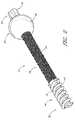
- FIG. 2is a side perspective view of the stabilization device of FIGS. 1A and 1B .
- FIG. 3is a side view of the stabilization device of FIG. 2 .
- FIG. 3Ais a cross-sectional view of a body portion of the stabilization device of FIG. 2 .
- FIG. 4is a partial cross-sectional view of a proximal portion of the stabilization device of FIG. 2 .
- FIG. 5is an enlarged view of a portion of FIG. 4 labeled 5 - 5 .
- FIG. 6is a side perspective view of a locking ring of the stabilization device of FIG. 3 .
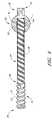
- FIG. 7is a side view of a modified embodiment of a body portion of the stabilization device shown in FIG. 2 .
- FIG. 7Ais an enlarged view of a portion of FIG. 7 labeled 7 A- 7 A.
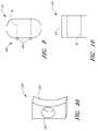
- FIG. 8is a side view of another modified embodiment of the proximal anchor.
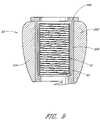
- FIG. 9is a top perspective view of a modified embodiment of the proximal anchor.
- FIG. 9Ais a side view of another modified embodiment of the proximal anchor.
- FIG. 10is a side view of another modified embodiment of the proximal anchor.
- stabilization devices of the present inventionwill be disclosed primarily in the context of a spinal stabilization procedure, the methods and structures disclosed herein are intended for application in any of a variety medical applications, as will be apparent to those of skill in the art in view of the disclosure herein.
- certain features and aspects of bone stabilization device and techniques described hereinmay be applicable to proximal fractures of the femur and a wide variety of fractures and osteotomies, the hand, such as interphalangeal and metacarpophalangeal arthrodesis, transverse phalangeal and metacarpal fracture fixation, spiral phalangeal and metacarpal fracture fixation, oblique phalangeal and metacarpal fracture fixation, intercondylar phalangeal and metacarpal fracture fixation, phalangeal and metacarpal osteotomy fixation as well as others known in the art. See e.g., U.S. Pat. No. 6,511,481, which is hereby incorporated by reference herein.
- a wide variety of phalangeal and metatarsal osteotomies and fractures of the footmay also be stabilized using the bone fixation devices described herein. These include, among others, distal metaphyseal osteotomies such as those described by Austin and Reverdin-Laird, base wedge osteotomies, oblique diaphyseal, digital arthrodesis as well as a wide variety of others that will be known to those of skill in the art.
- the stabilization devicesmay also be used to attach tissue or structure to the bone, such as in ligament reattachment and other soft tissue attachment procedures. Plates and washers, with or without tissue spikes for soft tissue attachment, and other implants may also be attached to bone, using either resorbable or nonresorbable fixation devices depending upon the implant and procedure.
- the stabilization devicesmay also be used to attach sutures to the bone, such as in any of a variety of tissue suspension procedures.
- the bone stabilization device described hereinmay be used with or without plate(s) or washer(s), all of which can be either permanent, absorbable, or combinations.
- FIGS. 1A and 1Bare side and rear elevational views of a pair of bone stabilization devices 12 , positioned within a vertebra 10 of the spine.
- the bone stabilization devices 12may be used in a variety of techniques to stabilize the spine.
- the distal end of the bone stabilization device 12is inserted into the pedicle of the vertebrae, preferably through the pars (i.e., the region of the lamina between the superior and inferior articular processes).
- the proximal end of the device 12extends above the pars such that it limits motion of the superior adjacent vertebrae with respect to the inferior articular process.
- the proximal end of the devicelimits motion by abutting and/or wedging against a surface of the superior adjacent vertebrae as the superior adjacent vertebrae moves relative to the inferior adjacent vertebrae. In this manner, at least one degree of motion between the inferior and superior vertebrae may be limited.
- the bone stabilization devices 12may be used after laminectomy, discectomy, artificial disc replacement, and other applications for providing temporary or permanent stability in the spinal column. For example, lateral or central spinal stenosis may be treated with the bone fixation devices 12 and techniques described below. In such procedures, the bone fixation devices 12 and techniques may be used alone or in combination with laminectomy, discectomy, artificial disc replacement, and/or other applications for relieving pain and/or providing stability.
- the stabilization device 12comprises a body 28 that extends between a proximal end 30 and a distal end 32 .
- the length, diameter and construction materials of the body 28can be varied, depending upon the intended clinical application. In embodiments optimized for spinal stabilization in an adult human population, the body 28 will generally be within the range of from about 20-90 mm in length and within the range of from about 3.0-8.5 mm in maximum diameter.
- the length of the helical anchordiscussed below, may be about 8-80 millimeters. Of course, it is understood that these dimensions are illustrative and that they may be varied as required for a particular patient or procedure.
- the body 28comprises titanium.
- other metals, or bioabsorbable or nonabsorbable polymeric materialsmay be utilized, depending upon the dimensions and desired structural integrity of the finished stabilization device 12 .
- the distal end 32 of the body 28is provided with a cancellous bone anchor or distal cortical bone anchor 34 .
- the distal bone anchor 34is adapted to be rotationally inserted into a portion (e.g., the facet or pedicle) of a first vertebra.
- the distal anchor 34comprises a helical locking structure 72 for engaging cancellous and/or distal cortical bone.
- the locking structure 72comprises a flange that is wrapped around a central core 73 , which in the illustrated embodiment is generally cylindrical in shape.
- the flange 72extends through at least one and generally from about two to about 50 or more full revolutions depending upon the axial length of the distal anchor 34 and intended application.
- the flangewill generally complete from about 2 to about 20 revolutions.
- the helical flange 72is preferably provided with a pitch and an axial spacing to optimize the retention force within cancellous bone.
- the helical flange 72 of the illustrated embodimenthas a generally triangular cross-sectional shape (see FIG. 3 ).
- the helical flange 72can have any of a variety of cross sectional shapes, such as rectangular, oval or other as deemed desirable for a particular application through routine experimentation in view of the disclosure herein.
- the flange 72has a triangular cross-sectional shape with a blunted or square apex.
- the outer edge of the helical flange 72defines an outer boundary.
- the ratio of the diameter of the outer boundary to the diameter of the central core 73can be optimized with respect to the desired retention force within the cancellous bone and giving due consideration to the structural integrity and strength of the distal anchor 34 .
- Another aspect of the distal anchor 34 that can be optimizedis the shape of the outer boundary and the central core 73 , which in the illustrated embodiment are generally cylindrical.
- the distal end 32 and/or the outer edges of the helical flange 72may be atraumatic (e.g., blunt or soft). This inhibits the tendency of the stabilization device 12 to migrate anatomically distally and potentially out of the vertebrae after implantation. Distal migration is also inhibited by the dimensions and presence of a proximal anchor 50 , which will be described below. In the spinal column, distal migration is particularly disadvantageous because the distal anchor 34 may harm the tissue, nerves, blood vessels and/or spinal cord which lie within and/or surround the spine. In other embodiments, the distal end 32 and/or the outer edges of the helical flange 72 may be sharp and/or configured such that the distal anchor 34 is self tapping and/or self drilling.
- the distal anchor 32may comprise a single helical thread surrounding a lumen, much as in a conventional corkscrew.
- a double helical threadmay be utilized, with the distal end of the first thread rotationally offset from the distal end of the second thread.
- distal anchor 34may be formed without a helical flange.
- various embodiments of levers, prongs, hooks and/or radially expandable devicesmay also be used. See e.g., U.S. Pat. No. 6,648,890, which is hereby expressly incorporated by reference in its entirety.
- the body 28is cannulated forming a central lumen 42 to accommodate installation over a placement wire as is understood in the art.
- the cross section of the illustrated central lumenis circular but in other embodiments may be non circular, e.g., hexagonal, to accommodate a corresponding male tool for installation or removal of the body 28 as explained below.
- the body 28may partially or wholly solid.
- the proximal end 30 of the body 28is provided with a rotational coupling 70 , for allowing the body 28 to be rotated.
- Rotation of the rotational coupling 70can be utilized to rotationally drive the distal anchor 32 into the bone.
- any of a variety of rotation devicesmay be utilized, such as electric drills or hand tools, which allow the clinician to manually rotate the proximal end 30 of the body 28 .
- the rotational coupling 70may have any of a variety of cross sectional configurations, such as one or more curved faces, flats or splines.
- the rotational coupling 70is a male element in the form of a hexagonal projection.
- the rotational coupling 70may be in the form of a female component, machined, milled or attached to the proximal end 30 of the body 28 .
- the rotational coupling 70comprises an axial recess with a polygonal cross section, such as a hexagonal cross section.
- the axial recessmay be provided as part of the central lumen 42 .
- the proximal end 30 of the fixation deviceis also provided with a proximal anchor 50 .
- the proximal anchor 50comprises a housing 52 , which forms a lumen 53 (see FIG. 5 ) configured such that the body 28 may extend, at least partially, through the proximal anchor 50 .
- the proximal anchor 50is axially distally moveable along the body 28 , to permit compression of between the distal and proximal ends 32 , 30 of the stabilization device 12 .
- complimentary locking structuressuch as threads, levers, split rings, and/or ratchet like structures between the proximal anchor 50 and the body 28 resist proximal movement of the anchor 50 with respect to the body 28 under normal use conditions.
- the proximal anchor 50preferably can be axially advanced along the body 28 with and/or without rotation as will be apparent from the disclosure herein.
- the complementary structure of the proximal anchor 50is formed by an annular ring 51 , which is positioned within an annular recess 55 formed along the lumen 53 .
- the ring 51comprises surface structures 54 which interact with complimentary surface structures 58 on the body 28 .
- the complimentary surface structures 58comprise a series of annular ridges or grooves 60 formed on the surface of the body 28 .
- the surface structures 54 and complementary surface structures 58permit distal axial travel of the proximal anchor 50 with respect to the body 28 , but resist proximal travel of the proximal anchor 50 with respect to the body 28 as explained below.
- the annular ring 51is split (i.e., has a least one gap) and is interposed between the body 28 and the recess 55 of the proximal anchor 50 (see FIG. 5 ).
- the ring 51comprises a tubular housing 57 (see FIG. 6 ), which defines a gap or space 59 .
- the gap 59is defined by a pair of edges 61 a , 61 b , that are generally straight and parallel to each other.
- the ring 51can be formed without a gap.
- the ring 51When the ring 51 is positioned along the body 28 , the ring 51 preferably surrounds a substantial portion of the body 28 .
- the ring 51can be configured so that the ring 51 can flex or move radially outwardly in response to an axial force so that the ring 51 can be moved relative to the body 28 , as described below.
- the tubular housing 57includes at least one and in the illustrated embodiment ten teeth or flanges 63 , which are configured to engage the complementary surface structures 58 on the body 28 in a ratchet-like motion.
- the teeth or flangesinclude a first surface 65 that lies generally perpendicular to the longitudinal axis of the anchor and generally faces the proximal direction (i.e., the direction labeled “P” in FIG. 5 ) and a second surface 67 that is inclined with respect to the longitudinal axis of the anchor and that faces distal direction (i.e., the direction labeled “D” in FIG. 5 ). It should be noted that the proximal and directions in FIG. 5 are reversed with respect to FIG. 4 .
- the recess 55is sized and dimensioned such that as the proximal anchor 50 is advanced distally over the body, the second surface 67 of the annular ring 51 can slide along and over the complementary retention structures 58 of the body 28 . That is, the recess 55 provides a space for the annular ring to move radially away from the body 28 as the proximal anchor 50 is advanced distally.
- a distal portion 69 of the recess 55is sized and dimensioned such that after the proximal anchor 50 is appropriately advanced, proximal motion of the proximal anchor 50 is resisted as the annular ring 51 becomes wedged between the body 28 and an angled engagement surface 71 of the distal portion 69 . In this manner, proximal movement of the proximal anchor 50 under normal use conditions may be prevented.
- the annular ring 51can be sized and dimensioned such that the ring 51 is biased inwardly to engage the retention structures 58 on the body 28 . The bias of the annular ring 51 can result in a more effective engagement between the complementary retention structures 58 of the body and the retention structures 54 of the ring 51 .
- retention structures 54 and complementary retention structures 58may be used between the body 28 and the proximal anchor 50 to permit distal axial travel of the proximal anchor 50 with respect to the body 28 , but resist proximal travel of the proximal anchor 50 with respect to the body 28 .
- Examples of such structurescan be found in U.S. Pat. No. 6,685,706, entitled “PROXIMAL ANCHORS FOR BONE FIXATION SYSTEM.” The entire contents of this patent is hereby expressly incorporated by reference herein.
- the complimentary surface structures 58 on the body 28comprise a series of annular ridges or grooves 60 . These retention structures 58 are spaced axially apart along the body 28 , between a proximal limit 62 and a distal limit 64 . See FIG. 4 .
- the axial distance between proximal limit 62 and distal limit 64is related to the desired axial working range of the proximal anchor 50 , and thus the range of functional sizes of the stabilization device 12 .
- the stabilization device 12 of the exemplary embodimentcan provide compression between the distal anchor 34 and the proximal anchor 50 throughout a range of motion following the placement of the distal anchor in a vertebra.
- the distal anchor 34may be positioned within the cancellous and/or distal cortical bone of a vertebra, and the proximal anchor may be distally advanced with respect to the distal anchor throughout a range to provide compression without needing to relocate the distal anchor 34 and without needing to initially locate the distal anchor 34 in a precise position with respect to the proximal side of the bone or another vertebra.
- Providing a working range throughout which tensioning of the proximal anchor 50 is independent from setting the distal anchor 34allows a single device to be useful for a wide variety of different anatomies, as well as eliminates or reduces the need for accurate device measurement.
- this arrangementallows the clinician to adjust the compression force during the procedure without adjusting the position of the distal anchor.
- the clinicianmay focus on positioning the distal anchor sufficiently within the vertebra to avoid or reduce the potential for distal migration out of the vertebra, which may damage the particularly delicate tissue, blood vessels, nerves and/or spinal cord surrounding or within the spinal column.
- the above described arrangementallows the clinician to adjust the positioning of the proximal anchor 50 with respect to the inferior articular process of the superior adjacent vertebrae.
- the clinicianmay adjust the position of the proximal anchor 50 without adjusting the position of the distal anchor such that the anchor 50 is configured to wedge or abut against inferior articular process of the superior adjacent vertebrae.
- the working rangeis at least about 10% of the overall length of the device, and may be as much as 20% or 50% or more of the overall device length.
- working ranges of up to about 10 mm or moremay be provided, since estimates within that range can normally be readily accomplished within the clinical setting.
- the embodiments disclosed hereincan be scaled to have a greater or a lesser working range, as will be apparent to those of skill in the art in view of the disclosure herein.
- the outer surface 49 of the proximal anchor 50has a smooth or spherical shape. As will be explained below, the outer surface 49 of the proximal anchor 50 is configured to abut against the inferior facet of the superior adjacent vertebrae. In this manner, motion between the adjacent vertebrae may be limited and/or constrained.
- FIG. 7illustrates an embodiment in which the body 28 comprises a first portion 36 and a second portion 38 that are coupled together at a junction 40 .
- the first portion 36carries the distal anchor 34 (shown without a central core) while the second portion 38 forms the proximal end 30 of the body 28 .
- the second portion 38may be used to pull the body 28 and therefore will sometimes be referred to as a “pull-pin.”
- the first and second portions 36 , 38are preferably detachably coupled to each other at the junction 40 .
- the first and second portions 36 , 38are detachably coupled to each other via interlocking threads. Specifically, as best seen in FIG.
- the body 28includes an inner surface 41 , which defines a central lumen 42 that preferably extends from the proximal end 30 to the distal end 32 throughout the body 28 .
- the inner surface 41includes a first threaded portion 44 .
- the first threaded portion 44is configured to mate with a second threaded portion 46 , which is located on the outer surface 45 of the second portion 38 .
- the interlocking annular threads of the first and second threaded portions 44 , 46allow the first and second portions 36 , 38 to be detachably coupled to each other. In one modified embodiment, the orientation of the first and second threaded portions 44 , 46 can be reversed.
- first threaded portion 44can be located on the outer surface of the first portion 36 and the second threaded portion 46 can be located on the inner surface 41 at the distal end of the second portion 38 .
- Any of a variety of other releasable complementary engagement structuresmay also be used, to allow removal of second portion 38 following implantation, as is discussed below.
- the second portion 38can comprise any of a variety of tensioning elements for permitting proximal tension to be placed on the distal anchor 34 while the proximal anchor is advanced distally to compress the fracture.
- tensioning elementsfor permitting proximal tension to be placed on the distal anchor 34 while the proximal anchor is advanced distally to compress the fracture.
- any of a variety of tubes or wirescan be removably attached to the first portion 36 and extend proximally to the proximal handpiece.
- the first portion 36can include a releasable connector in the form of a latching element, such as an eye or hook.
- the second portion 38can include a complementary releasable connector (e.g., a complementary hook) for engaging the first portion 36 .
- the second portion 38can be detachably coupled to the first portion 36 such proximal traction can be applied to the first portion 36 through the second portion as will be explained below.
- the second portion 48may be provided with an eye or hook, or transverse bar, around which or through which a suture or wire may be advanced, both ends of which are retained at the proximal end of the device. Following proximal tension on the tensioning element during the compression step, one end of the suture or wire is released, and the other end may be pulled free of the device.
- Alternate releasable proximal tensioning structuresmay be devised by those of skill in the art in view of the disclosure herein.
- the distal end of the proximal anchor 50preferably extends distally past the junction 40 between the first portion 36 and the second portion 38 .
- the proximal anchor 50is provided with one or more surface structures 54 for cooperating with complementary surface structures 58 on the first portion 36 of the body 28 .
- the stabilization device 12may include an antirotation lock (not shown) between the first portion 36 of the body 28 and the proximal collar 50 .
- the first portion 36may include one or more of flat sides (not shown), which interact with corresponding flat structures in the proximal collar 50 .
- rotation of the proximal collar 50is transmitted to the first portion 36 and distal anchor 34 of the body 28 .
- splines or other interfit structurescan be used to prevent relative rotation of the proximal anchor and the first portion 36 of the body 28 .
- the housing 52may be provided with a gripping structure (not shown) to permit an insertion tool to rotate the flange proximal anchor 50 .
- a gripping structure(not shown) to permit an insertion tool to rotate the flange proximal anchor 50 .
- Any of a variety of gripping structuresmay be provided, such as one or more slots, recesses, protrusions, flats, bores or the like.
- the proximal end of the proximal anchor 50is provided with a polygonal, and, in particular, a pentagonal or hexagonal recess or protrusion.
- the distal end of the proximal anchor 50may include one or more bone engagement features 100 , which in the illustrated embodiment comprises a one or more spikes 102 positioned on a contacting surface 104 of the proximal anchors.
- the spikes 102provide additional gripping support especially when the proximal anchor 50 is positioned against, for example, uneven bone surfaces and/or soft tissue.
- the spikes 102may limit rotation of the proximal anchor 50 with respect to the body 28 thereby preventing the proximal anchor 50 from backing off the body 28 .
- Other structures for the bone engagement feature 100may also be used, such as, for example, ridges, serrations etc.
- a patient with a spinal instabilityis identified.
- the patientis preferably positioned face down on an operating table, placing the spinal column into a flexed position.
- a trocarmay then be inserted through a tissue tract and advanced towards a first vertebral body.
- a guidewiremay then be advanced through the trocar and into the first vertebral body.
- the guide wireis preferably inserted into the pedicle of the vertebral body preferably through the pars (i.e. the region of the lamina between the superior and inferior articular processes).
- a suitable tissue expandermay then be inserted over the guidewire and expanded to enlarge the tissue tract.
- a surgical sheathmay then be advanced over the expanded tissue expander.
- a drill with a rotatable tipmay be advanced over the guidewire and through the sheath.
- the drillmay be used to drill an opening in the vertebral body.
- the openingmay be configured for (i) for insertion of the body 28 of the bone stabilization device 12 , (ii) taping and/or (iii) providing a counter sink for the proximal anchor 50 .
- the step of drillingmay be omitted.
- the distal anchor 34is preferably self-tapping and self drilling.
- the body 28 of the fixation devicemay be advanced over the guidewire and through the sheath until it engages the vertebral body.
- the body 28may be coupled to a suitable insertion tool prior to the step of engaging the fixation device 12 with the vertebral body.
- the insertion toolmay be configured to engage the coupling 70 on the proximal end of the body 28 such that insertion tool may be used to rotate the body 28 .
- the fixation device 12is preferably configured such that it can also be advanced over the guidewire.
- the insertion toolmay be used to rotate the body 28 thereby driving the distal anchor 34 to the desired depth within the pedicle of the vertebral body.
- the proximal anchor 50may be carried by the fixation device prior to advancing the body 28 into the vertebrae, or may be attached following placement (partially or fully) of the body 28 within the vertebrae.
- the clinicianwill have access to an array of devices 12 , having, for example, different diameters, axial lengths, configurations and/or shapes. The clinician will assess the position of the body 28 with respect to the superior vertebral body and chose the proximal anchor 50 from the array, which best fits the patient anatomy to achieve the desired clinical result.
- the proximal anchor 50is preferably advanced over the body 28 until it reaches its desired position. This may be accomplished by pushing on the proximal anchor 50 or by applying a distal force to the proximal anchor 50 . In another embodiment, the proximal anchor 50 is advanced by applying a proximal retraction force to the proximal end 30 of body 28 , such as by conventional hemostats, pliers or a calibrated loading device, while distal force is applied to the proximal anchor 50 .
- proximal anchor 50is advanced distally with respect to the body 28 until the proximal anchor 50 is in its proper position (e.g., positioned snugly against the outer surface of the vertebra.)
- Appropriate tensioning of the stabilization device 12can be accomplished by tactile feedback or through the use of a calibration device for applying a predetermined load on the stabilization device 12 .
- one advantage of the structure of the illustrated embodimentsis the ability to adjust compression independently of the setting of the distal anchor 34 within the vertebra.
- the proximal portion of the body 28 extending proximally from the proximal anchor 50can be removed. In one embodiment, this may involve cutting the proximal end of the body 28 .
- the proximal end of the bodymay be separated by a cutting instrument or by cauterizing.
- Cauterizingmay fuse the proximal anchor 50 to the body 32 thereby adding to the retention force between the proximal anchor 50 and the body 28 .
- Such fusion between the proximal anchor and the bodymay be particularly advantageous if the pin and the proximal anchor are made from a polymeric or plastic material.
- the bodycomprises a first and a second portion 36 , 38 as described above.
- the second portion 38may detached from the first portion 36 and removed. In the illustrated embodiment, this involves rotating the second portion 38 with respect to the first portion via the coupling 70 .
- the proximal end of the body 28may remain attached to the body 28 .
- the access sitemay be closed and dressed in accordance with conventional wound closure techniques and the steps described above may be repeated on the other side of the vertebral body for bilateral symmetry as shown in FIGS. 1A and 1B .
- the bone stabilization devices 12may be used alone or in combination laminectomy, discectomy, artificial disc replacement, and/or other applications for relieving pain and/or providing stability.
- the proximal anchors 50 of the devices 12extend above the pars such that they abut against the inferior facet of the superior adjacent vertebrae.
- the proximal anchor 50forms a wedge between the vertebral bodies limiting compression of the spine as the facet of the superior adjacent vertebrae abuts against the proximal anchor 50 .
- compressionis limited while other motion is not.
- flexion, lateral movement and torsion between the superior and inferior vertebral bodiesis not limited or constrained. In this manner, the natural motion of the spine can be preserved, especially for those patients with mild or moderate disc conditions.
- the devicesare implantable through a minimally invasive procedure and, more preferably, through the use of small percutaneous openings as described above. In this manner, the high cost, lengthy in-patient hospital stays and the pain associated with open procedures can be avoided and/or reduced.
- the devices 12may be removed and/or proximal anchors 50 may be removed in a subsequent procedure if the patient's condition improves.
- the proximal anchor 50may be positioned such that it contacts surfaces of the adjacent vertebrae all of the time, most of the time or only when movement between the adjacent vertebrae exceeds a limit.
- proximal anchorit may be advantageous to allow the proximal anchor to rotate with respect to the body 28 thereby preventing the proximal anchor 50 from causing the distal anchor 34 from backing out of the pedicle.
- engagement features 100may be added to the proximal anchor 50 as described above to prevent rotation of the proximal anchor 50 .
- the fixation devices 12may be made from conventional non-absorbable, biocompatible materials including stainless steel, titanium, alloys thereof, polymers, composites and the like and equivalents thereof.
- the distal anchorcomprises a metal helix, while the body and the proximal anchor comprise a bioabsorbable material.
- the distal anchorcomprises a bioabsorbable material, and the body and proximal anchor comprise either a bioabsorbable material or a non-absorbable material.
- the proximal anchor 50is formed, at least in part, from an elastic and/or resilient material. In this manner, the shock and forces that are generated as the proximal anchor abuts or wedges against the inferior articular process of the superior adjacent vertebrae can be reduced or dissipated.
- the proximal anchor 50is formed in part by a polycarbonate urethane or a hydrogel.
- the elastic materialmay be positioned on the outer surfaces of the proximal anchor or the portions of the outer surfaces that abut against the surfaces of the inferior articular process of the superior adjacent vertebrae.
- FIG. 9illustrates an embodiment of a proximal anchor 50 ′, which comprises an outer housing or shell 202 .
- the shell 202may be formed or a resilient material such as, for example, a biocompatible polymer.
- the proximal anchor 50 ′also comprises an inner member 204 that comprises a tubular housing 206 and a proximal flange 208 .
- the inner member 202is preferably formed of a harder more rugged material as compared to the shell 202 , such as, for example, titanium or another metallic material.
- the shell 202is fitted or formed over the tubular housing 206 . When deployed, the shell 202 is held in place between the flange 208 and the surface of the vertebrae in which the body 202 is placed.
- the shell 202may be coupled to the inner member 204 in a variety of other manners, such as, adhesives, fasteners, interlocking surfaces structures and the like.
- the inner member 204includes a locking ring 51 positioned within a recess 55 as described above.
- other retention structures 54 and complementary retention structures 58may be used between the body 28 and the proximal anchor 50 ′ to permit distal axial travel of the proximal anchor 50 ′ with respect to the body 28 , but resist proximal travel of the proximal anchor 50 ′ with respect to the body 28 .
- FIGS. 9A and 10illustrate modified shapes of the proximal anchor which can be used alone or in combination with the elastic or resilient material described above.
- the proximal anchor 250has a saddle shaped curved surface 251 that generally faces the inferior articular process of the superior adjacent vertebrae.
- the saddle shaped surfacemay limit compression of the adjacent vertebral bodies and limit side to side motion and/or torsion between the vertebral bodies.
- FIG. 10illustrates an embodiment in which the proximal anchor 350 has a rectangular shape with a flat shaped surface 351 .
- the flat shaped surfacemay limit compression of the adjacent vertebral bodies and limit side to side motion between the vertebral bodies.
- FIGS. 9Aillustrate modified shapes of the proximal anchor which can be used alone or in combination with the elastic or resilient material described above.
- the proximal anchor 250has a saddle shaped curved surface 251 that generally faces the inferior articular process of the superior adjacent vertebrae.
- the saddle shaped surfacemay limit compression of the
- the proximal anchor 50in may be advantageous to limit or eliminate any rotation of the proximal anchor 50 with respect to the body 28 and/or the vertebral body.
- the proximal anchor 50preferably includes the retention devices 100 described above with reference to FIG. 8 .
- the above described devices and techniqueslimit motion of the spine by providing an abutment or wedge surface on one vertebral body.
- the abutment surfacecontacts a portion of a second, adjacent vertebral body so as limit least one degree of motion between the two vertebral bodies while permitting at least one other degree of motion. While the above described devices and techniques are generally preferred, certain features and aspects can be extended to modified embodiments for limiting motion between vertebral bodies. These modified embodiments will now be described.
- the proximal anchor 50 of the fixation devicemay be, coupled to attached or integrally formed with the body 28 . In this manner, movement between the proximal anchor 50 and the body 28 is not permitted. Instead, the clinician may chose a fixation device of the proper length and advance the device into the vertebral body until the proximal anchor lies flush with the vertebral body or is otherwise positioned accordingly with respect to the vertebral body.
- the abutment surfacemay be attached to the vertebral body through the use of an adhesive, fasteners, staples, screws and the like
- the abutment surfacemay formed on a distal end of a stabilization device that is inserted through the front side of the vertebral body.
- the clinicianwill have access to an array of fixation devices 12 , having, for example, different diameters, axial lengths and, if applicable, angular relationships. These may be packaged one or more per package in sterile or non-sterile envelopes or peelable pouches, or in dispensing cartridges which may each hold a plurality of devices 12 . The clinician will assess the dimensions and load requirements, and select a fixation device from the array, which meets the desired specifications.
- the fixation devicesmay also be made from conventional non-absorbable, biocompatible materials including stainless steel, titanium, alloys thereof, polymers, composites and the like and equivalents thereof.
- the distal anchorcomprises a metal helix, while the body and the proximal anchor comprise a bioabsorbable material.
- the bodyis made of PEEKTM polymer or similar plastic material.
- the distal anchorcomprises a bioabsorbable material, and the body and proximal anchor comprise either a bioabsorbable material or a non-absorbable material.
- each of the distal anchor and the bodycomprise a non-absorbable material, connected by an absorbable link. This may be accomplished by providing a concentric fit between the distal anchor and the body, with a transverse absorbable pin extending therethrough. This embodiment will enable removal of the body following dissipation of the pin, while leaving the distal anchor within the bone.
- the components of the present inventionmay be sterilized by any of the well known sterilization techniques, depending on the type of material. Suitable sterilization techniques include heat sterilization, radiation sterilization, such as cobalt 60 irradiation or electron beams, ethylene oxide sterilization, and the like.
- any of the bone fixation devices of the present inventioncan be readily varied depending upon the intended application, as will be apparent to those of skill in the art in view of the disclosure herein.
- the present inventionhas been described in terms of certain preferred embodiments, other embodiments of the invention including variations in dimensions, configuration and materials will be apparent to those of skill in the art in view of the disclosure herein.
- all features discussed in connection with any one embodiment hereincan be readily adapted for use in other embodiments herein.
- the use of different terms or reference numerals for similar features in different embodimentsdoes not imply differences other than those which may be expressly set forth. Accordingly, the present invention is intended to be described solely by reference to the appended claims, and not limited to the preferred embodiments disclosed herein.
Landscapes
- Health & Medical Sciences (AREA)
- Surgery (AREA)
- Orthopedic Medicine & Surgery (AREA)
- Life Sciences & Earth Sciences (AREA)
- Heart & Thoracic Surgery (AREA)
- Veterinary Medicine (AREA)
- Engineering & Computer Science (AREA)
- Biomedical Technology (AREA)
- Nuclear Medicine, Radiotherapy & Molecular Imaging (AREA)
- Medical Informatics (AREA)
- Molecular Biology (AREA)
- Animal Behavior & Ethology (AREA)
- General Health & Medical Sciences (AREA)
- Public Health (AREA)
- Neurology (AREA)
- Dentistry (AREA)
- Oral & Maxillofacial Surgery (AREA)
- Surgical Instruments (AREA)
- Prostheses (AREA)
Abstract
Description
Claims (25)
Priority Applications (16)
| Application Number | Priority Date | Filing Date | Title |
|---|---|---|---|
| US11/056,991US7648523B2 (en) | 2004-12-08 | 2005-02-11 | Method and apparatus for spinal stabilization |
| US11/185,442US7857832B2 (en) | 2004-12-08 | 2005-07-20 | Method and apparatus for spinal stabilization |
| US11/296,881US7901438B2 (en) | 2004-12-08 | 2005-12-08 | Method and apparatus for spinal stabilization |
| JP2007545602AJP2008522746A (en) | 2004-12-08 | 2005-12-08 | Spine stabilization method and spine stabilization device |
| EP05853282AEP1845874B1 (en) | 2004-12-08 | 2005-12-08 | Apparatus for spinal stabilization |
| AU2005314079AAU2005314079B2 (en) | 2004-12-08 | 2005-12-08 | Method and apparatus for spinal stabilization |
| ES05853282TES2396912T3 (en) | 2004-12-08 | 2005-12-08 | Apparatus for stabilization of the spine |
| PCT/US2005/044321WO2006063083A1 (en) | 2004-12-08 | 2005-12-08 | Method and apparatus for spinal stabilization |
| US12/686,262US9445826B2 (en) | 2004-12-08 | 2010-01-12 | Method and apparatus for spinal stabilization |
| US13/035,889US9226758B2 (en) | 2004-12-08 | 2011-02-25 | Method and apparatus for spinal stabilization |
| US14/957,422US10070893B2 (en) | 2004-12-08 | 2015-12-02 | Method and apparatus for spinal stabilization |
| US15/238,121US9962189B2 (en) | 2004-12-08 | 2016-08-16 | Method and apparatus for spinal stabilization |
| US15/953,855US10639074B2 (en) | 2004-12-08 | 2018-04-16 | Method and apparatus for spinal stabilization |
| US16/100,764US10667844B2 (en) | 2004-12-08 | 2018-08-10 | Method and apparatus for spinal stabilization |
| US16/864,556US20200337732A1 (en) | 2004-12-08 | 2020-05-01 | Method and apparatus for spinal stabilization |
| US16/885,868US20200352605A1 (en) | 2004-12-08 | 2020-05-28 | Method and apparatus for spinal stabilization |
Applications Claiming Priority (2)
| Application Number | Priority Date | Filing Date | Title |
|---|---|---|---|
| US63420304P | 2004-12-08 | 2004-12-08 | |
| US11/056,991US7648523B2 (en) | 2004-12-08 | 2005-02-11 | Method and apparatus for spinal stabilization |
Related Child Applications (2)
| Application Number | Title | Priority Date | Filing Date |
|---|---|---|---|
| US11/185,442Continuation-In-PartUS7857832B2 (en) | 2004-12-08 | 2005-07-20 | Method and apparatus for spinal stabilization |
| US12/686,262DivisionUS9445826B2 (en) | 2004-12-08 | 2010-01-12 | Method and apparatus for spinal stabilization |
Publications (2)
| Publication Number | Publication Date |
|---|---|
| US20060122609A1 US20060122609A1 (en) | 2006-06-08 |
| US7648523B2true US7648523B2 (en) | 2010-01-19 |
Family
ID=36575364
Family Applications (5)
| Application Number | Title | Priority Date | Filing Date |
|---|---|---|---|
| US11/056,991Active2027-09-04US7648523B2 (en) | 2004-12-08 | 2005-02-11 | Method and apparatus for spinal stabilization |
| US12/686,262Expired - Fee RelatedUS9445826B2 (en) | 2004-12-08 | 2010-01-12 | Method and apparatus for spinal stabilization |
| US15/238,121Expired - LifetimeUS9962189B2 (en) | 2004-12-08 | 2016-08-16 | Method and apparatus for spinal stabilization |
| US15/953,855Expired - Fee RelatedUS10639074B2 (en) | 2004-12-08 | 2018-04-16 | Method and apparatus for spinal stabilization |
| US16/864,556AbandonedUS20200337732A1 (en) | 2004-12-08 | 2020-05-01 | Method and apparatus for spinal stabilization |
Family Applications After (4)
| Application Number | Title | Priority Date | Filing Date |
|---|---|---|---|
| US12/686,262Expired - Fee RelatedUS9445826B2 (en) | 2004-12-08 | 2010-01-12 | Method and apparatus for spinal stabilization |
| US15/238,121Expired - LifetimeUS9962189B2 (en) | 2004-12-08 | 2016-08-16 | Method and apparatus for spinal stabilization |
| US15/953,855Expired - Fee RelatedUS10639074B2 (en) | 2004-12-08 | 2018-04-16 | Method and apparatus for spinal stabilization |
| US16/864,556AbandonedUS20200337732A1 (en) | 2004-12-08 | 2020-05-01 | Method and apparatus for spinal stabilization |
Country Status (2)
| Country | Link |
|---|---|
| US (5) | US7648523B2 (en) |
| JP (1) | JP2008522746A (en) |
Cited By (63)
| Publication number | Priority date | Publication date | Assignee | Title |
|---|---|---|---|---|
| US20090177205A1 (en)* | 2008-01-09 | 2009-07-09 | Providence Medical Technology, Inc. | Methods and apparatus for accessing and treating the facet joint |
| US20090306671A1 (en)* | 2008-06-06 | 2009-12-10 | Providence Medical Technology, Inc. | Facet joint implants and delivery tools |
| US20090312763A1 (en)* | 2008-06-06 | 2009-12-17 | Mccormack Bruce M | Facet joint implants and delivery tools |
| US20100069912A1 (en)* | 2008-06-06 | 2010-03-18 | Mccormack Bruce M | Cervical distraction/implant delivery device |
| US7824431B2 (en) | 2006-12-29 | 2010-11-02 | Providence Medical Technology, Inc. | Cervical distraction method |
| US20110040332A1 (en)* | 2009-08-11 | 2011-02-17 | Interventional Spine, Inc. | Spinous process spacer and implantation procedure |
| US20110160772A1 (en)* | 2009-12-28 | 2011-06-30 | Arcenio Gregory B | Systems and methods for performing spinal fusion |
| US8394129B2 (en) | 2011-03-10 | 2013-03-12 | Interventional Spine, Inc. | Method and apparatus for minimally invasive insertion of intervertebral implants |
| US8518087B2 (en) | 2011-03-10 | 2013-08-27 | Interventional Spine, Inc. | Method and apparatus for minimally invasive insertion of intervertebral implants |
| US20130238036A1 (en)* | 2010-11-30 | 2013-09-12 | Genossis Llc | Bone Compression and Fixation Devices |
| USD732667S1 (en) | 2012-10-23 | 2015-06-23 | Providence Medical Technology, Inc. | Cage spinal implant |
| USD745156S1 (en) | 2012-10-23 | 2015-12-08 | Providence Medical Technology, Inc. | Spinal implant |
| US9277928B2 (en) | 2013-03-11 | 2016-03-08 | Interventional Spine, Inc. | Method and apparatus for minimally invasive insertion of intervertebral implants |
| US9333086B2 (en) | 2008-06-06 | 2016-05-10 | Providence Medical Technology, Inc. | Spinal facet cage implant |
| US9381049B2 (en) | 2008-06-06 | 2016-07-05 | Providence Medical Technology, Inc. | Composite spinal facet implant with textured surfaces |
| US9522070B2 (en) | 2013-03-07 | 2016-12-20 | Interventional Spine, Inc. | Intervertebral implant |
| US9713486B2 (en) | 2002-07-19 | 2017-07-25 | DePuy Synthes Products, Inc. | Method and apparatus for spinal fixation |
| US9839530B2 (en) | 2007-06-26 | 2017-12-12 | DePuy Synthes Products, Inc. | Highly lordosed fusion cage |
| US9883951B2 (en) | 2012-08-30 | 2018-02-06 | Interventional Spine, Inc. | Artificial disc |
| US9895236B2 (en) | 2010-06-24 | 2018-02-20 | DePuy Synthes Products, Inc. | Enhanced cage insertion assembly |
| US9913727B2 (en) | 2015-07-02 | 2018-03-13 | Medos International Sarl | Expandable implant |
| US9931223B2 (en) | 2008-04-05 | 2018-04-03 | DePuy Synthes Products, Inc. | Expandable intervertebral implant |
| US9962189B2 (en) | 2004-12-08 | 2018-05-08 | Decima Spine, Inc. | Method and apparatus for spinal stabilization |
| US9993349B2 (en) | 2002-06-27 | 2018-06-12 | DePuy Synthes Products, Inc. | Intervertebral disc |
| US9993353B2 (en) | 2013-03-14 | 2018-06-12 | DePuy Synthes Products, Inc. | Method and apparatus for minimally invasive insertion of intervertebral implants |
| US10058433B2 (en) | 2012-07-26 | 2018-08-28 | DePuy Synthes Products, Inc. | Expandable implant |
| US10070893B2 (en) | 2004-12-08 | 2018-09-11 | Decima Spine, Inc. | Method and apparatus for spinal stabilization |
| US10201375B2 (en) | 2014-05-28 | 2019-02-12 | Providence Medical Technology, Inc. | Lateral mass fixation system |
| USD841165S1 (en) | 2015-10-13 | 2019-02-19 | Providence Medical Technology, Inc. | Cervical cage |
| US10390963B2 (en) | 2006-12-07 | 2019-08-27 | DePuy Synthes Products, Inc. | Intervertebral implant |
| US10398563B2 (en) | 2017-05-08 | 2019-09-03 | Medos International Sarl | Expandable cage |
| US10433977B2 (en) | 2008-01-17 | 2019-10-08 | DePuy Synthes Products, Inc. | Expandable intervertebral implant and associated method of manufacturing the same |
| US10500062B2 (en) | 2009-12-10 | 2019-12-10 | DePuy Synthes Products, Inc. | Bellows-like expandable interbody fusion cage |
| US10537436B2 (en) | 2016-11-01 | 2020-01-21 | DePuy Synthes Products, Inc. | Curved expandable cage |
| US10548741B2 (en) | 2010-06-29 | 2020-02-04 | DePuy Synthes Products, Inc. | Distractible intervertebral implant |
| US10682243B2 (en) | 2015-10-13 | 2020-06-16 | Providence Medical Technology, Inc. | Spinal joint implant delivery device and system |
| USD887552S1 (en) | 2016-07-01 | 2020-06-16 | Providence Medical Technology, Inc. | Cervical cage |
| US10888433B2 (en) | 2016-12-14 | 2021-01-12 | DePuy Synthes Products, Inc. | Intervertebral implant inserter and related methods |
| USD911525S1 (en) | 2019-06-21 | 2021-02-23 | Providence Medical Technology, Inc. | Spinal cage |
| US10940016B2 (en) | 2017-07-05 | 2021-03-09 | Medos International Sarl | Expandable intervertebral fusion cage |
| US11065039B2 (en) | 2016-06-28 | 2021-07-20 | Providence Medical Technology, Inc. | Spinal implant and methods of using the same |
| USD933230S1 (en) | 2019-04-15 | 2021-10-12 | Providence Medical Technology, Inc. | Cervical cage |
| US11224521B2 (en) | 2008-06-06 | 2022-01-18 | Providence Medical Technology, Inc. | Cervical distraction/implant delivery device |
| USD945621S1 (en) | 2020-02-27 | 2022-03-08 | Providence Medical Technology, Inc. | Spinal cage |
| US11272964B2 (en) | 2008-06-06 | 2022-03-15 | Providence Medical Technology, Inc. | Vertebral joint implants and delivery tools |
| US11344424B2 (en) | 2017-06-14 | 2022-05-31 | Medos International Sarl | Expandable intervertebral implant and related methods |
| US11426290B2 (en) | 2015-03-06 | 2022-08-30 | DePuy Synthes Products, Inc. | Expandable intervertebral implant, system, kit and method |
| US11426286B2 (en) | 2020-03-06 | 2022-08-30 | Eit Emerging Implant Technologies Gmbh | Expandable intervertebral implant |
| US11446156B2 (en) | 2018-10-25 | 2022-09-20 | Medos International Sarl | Expandable intervertebral implant, inserter instrument, and related methods |
| US11452607B2 (en) | 2010-10-11 | 2022-09-27 | DePuy Synthes Products, Inc. | Expandable interspinous process spacer implant |
| US11510788B2 (en) | 2016-06-28 | 2022-11-29 | Eit Emerging Implant Technologies Gmbh | Expandable, angularly adjustable intervertebral cages |
| US11596522B2 (en) | 2016-06-28 | 2023-03-07 | Eit Emerging Implant Technologies Gmbh | Expandable and angularly adjustable intervertebral cages with articulating joint |
| US11612491B2 (en) | 2009-03-30 | 2023-03-28 | DePuy Synthes Products, Inc. | Zero profile spinal fusion cage |
| US11648128B2 (en) | 2018-01-04 | 2023-05-16 | Providence Medical Technology, Inc. | Facet screw and delivery device |
| US11752009B2 (en) | 2021-04-06 | 2023-09-12 | Medos International Sarl | Expandable intervertebral fusion cage |
| US11850160B2 (en) | 2021-03-26 | 2023-12-26 | Medos International Sarl | Expandable lordotic intervertebral fusion cage |
| US11871968B2 (en) | 2017-05-19 | 2024-01-16 | Providence Medical Technology, Inc. | Spinal fixation access and delivery system |
| US11911287B2 (en) | 2010-06-24 | 2024-02-27 | DePuy Synthes Products, Inc. | Lateral spondylolisthesis reduction cage |
| USRE49973E1 (en) | 2013-02-28 | 2024-05-21 | DePuy Synthes Products, Inc. | Expandable intervertebral implant, system, kit and method |
| US12004781B2 (en) | 2014-05-27 | 2024-06-11 | Providence Medical Technology, Inc. | Lateral mass fixation implant |
| US12090064B2 (en) | 2022-03-01 | 2024-09-17 | Medos International Sarl | Stabilization members for expandable intervertebral implants, and related systems and methods |
| US12144513B2 (en) | 2018-09-21 | 2024-11-19 | Providence Medical Technology, Inc. | Vertebral joint access and decortication devices and methods of using |
| USD1098431S1 (en) | 2023-02-27 | 2025-10-14 | Providence Medical Technology, Inc. | Spinal cage |
Families Citing this family (15)
| Publication number | Priority date | Publication date | Assignee | Title |
|---|---|---|---|---|
| US6887243B2 (en) | 2001-03-30 | 2005-05-03 | Triage Medical, Inc. | Method and apparatus for bone fixation with secondary compression |
| US6511481B2 (en)* | 2001-03-30 | 2003-01-28 | Triage Medical, Inc. | Method and apparatus for fixation of proximal femoral fractures |
| WO2006116119A2 (en)* | 2005-04-21 | 2006-11-02 | Spine Wave, Inc. | Dynamic stabilization system for the spine |
| US8133261B2 (en) | 2007-02-26 | 2012-03-13 | Depuy Spine, Inc. | Intra-facet fixation device and method of use |
| US8197513B2 (en) | 2007-04-13 | 2012-06-12 | Depuy Spine, Inc. | Facet fixation and fusion wedge and method of use |
| US8894685B2 (en) | 2007-04-13 | 2014-11-25 | DePuy Synthes Products, LLC | Facet fixation and fusion screw and washer assembly and method of use |
| US8043334B2 (en)* | 2007-04-13 | 2011-10-25 | Depuy Spine, Inc. | Articulating facet fusion screw |
| US7998176B2 (en) | 2007-06-08 | 2011-08-16 | Interventional Spine, Inc. | Method and apparatus for spinal stabilization |
| US20100191291A1 (en)* | 2009-01-29 | 2010-07-29 | Phan Christopher U | Bone fixation device and methods for treating spinal stenosis |
| US9566098B2 (en) | 2009-04-23 | 2017-02-14 | University Of Massachusetts | Bone fixture assembly |
| WO2010124230A1 (en) | 2009-04-23 | 2010-10-28 | University Of Massachusetts | Bone fixture assembly |
| US9089372B2 (en) | 2010-07-12 | 2015-07-28 | DePuy Synthes Products, Inc. | Pedicular facet fusion screw with plate |
| EP2772212B1 (en)* | 2013-03-01 | 2019-05-08 | Biedermann Technologies GmbH & Co. KG | Instrument for inserting a bone anchoring element and system of such an instrument and a polyaxial bone anchoring element |
| US9522028B2 (en) | 2013-07-03 | 2016-12-20 | Interventional Spine, Inc. | Method and apparatus for sacroiliac joint fixation |
| US10952866B2 (en) | 2015-10-13 | 2021-03-23 | DePuy Synthes Products, Inc. | Intervertebral implant and bone graft inserter |
Citations (84)
| Publication number | Priority date | Publication date | Assignee | Title |
|---|---|---|---|---|
| US2570465A (en) | 1949-08-01 | 1951-10-09 | Joseph S Lundholm | Means for fixation of hip fractures |
| US4456005A (en) | 1982-09-30 | 1984-06-26 | Lichty Terry K | External compression bone fixation device |
| US4940467A (en) | 1988-02-03 | 1990-07-10 | Tronzo Raymond G | Variable length fixation device |
| US5116336A (en) | 1990-03-19 | 1992-05-26 | Synthes (U.S.A.) | Osteosynthetic anchor bolt |
| US5122133A (en) | 1990-10-26 | 1992-06-16 | Smith & Nephew Richards Inc. | Compression screw for a joint endoprosthesis |
| US5167664A (en) | 1991-08-26 | 1992-12-01 | Zimmer, Inc. | Ratcheting bone screw |
| US5217462A (en) | 1991-03-05 | 1993-06-08 | Pfizer Hospital Products Group, Inc. | Screw and driver |
| US5334184A (en) | 1992-06-30 | 1994-08-02 | Bimman Lev A | Apparatus for intramedullary fixation broken bones |
| EP0625336A2 (en) | 1993-04-21 | 1994-11-23 | AMEI TECHNOLOGIES Inc. | System and method for securing a medical cable |
| US5382248A (en) | 1992-09-10 | 1995-01-17 | H. D. Medical, Inc. | System and method for stabilizing bone segments |
| US5387213A (en) | 1991-02-05 | 1995-02-07 | Safir S.A.R.L. | Osseous surgical implant particularly for an intervertebral stabilizer |
| US5415661A (en) | 1993-03-24 | 1995-05-16 | University Of Miami | Implantable spinal assist device |
| US5496318A (en) | 1993-01-08 | 1996-03-05 | Advanced Spine Fixation Systems, Inc. | Interspinous segmental spine fixation device |
| US5498265A (en) | 1991-03-05 | 1996-03-12 | Howmedica Inc. | Screw and driver |
| US5520690A (en) | 1995-04-13 | 1996-05-28 | Errico; Joseph P. | Anterior spinal polyaxial locking screw plate assembly |
| US5527312A (en) | 1994-08-19 | 1996-06-18 | Salut, Ltd. | Facet screw anchor |
| US5540688A (en) | 1991-05-30 | 1996-07-30 | Societe "Psi" | Intervertebral stabilization device incorporating dampers |
| US5558674A (en) | 1993-12-17 | 1996-09-24 | Smith & Nephew Richards, Inc. | Devices and methods for posterior spinal fixation |
| US5569248A (en)* | 1992-03-17 | 1996-10-29 | Danek Medical, Inc. | Apparatus for subcutaneous suprafascial pedicular internal fixation |
| US5569548A (en) | 1993-08-05 | 1996-10-29 | Murata Manufacturing Co., Ltd. | Zinc oxide piezoelectric crystal film on sapphire plane |
| US5609634A (en) | 1992-07-07 | 1997-03-11 | Voydeville; Gilles | Intervertebral prosthesis making possible rotatory stabilization and flexion/extension stabilization |
| US5645599A (en) | 1994-07-26 | 1997-07-08 | Fixano | Interspinal vertebral implant |
| US5667508A (en) | 1996-05-01 | 1997-09-16 | Fastenetix, Llc | Unitary locking cap for use with a pedicle screw |
| US5893850A (en) | 1996-11-12 | 1999-04-13 | Cachia; Victor V. | Bone fixation device |
| US5989255A (en) | 1998-08-06 | 1999-11-23 | Smith & Nephew | Orthopaedic done screw apparatus |
| US5997538A (en) | 1998-03-23 | 1999-12-07 | New York Society For The Ruptured And Crippled Maintaining The Hospital For Special Surgery | Rotationally ratcheting bone screw |
| US6004327A (en) | 1993-08-03 | 1999-12-21 | Stryker Technologies Corporation | Ratcheting compression device |
| US6048342A (en) | 1997-01-02 | 2000-04-11 | St. Francis Medical Technologies, Inc. | Spine distraction implant |
| US6287313B1 (en) | 1999-11-23 | 2001-09-11 | Sdgi Holdings, Inc. | Screw delivery system and method |
| US6361538B1 (en) | 2000-01-31 | 2002-03-26 | Depuy Orthopaedics, Inc. | Method for treating orthopedic fractures with a fixation member |
| US6379355B1 (en) | 1997-01-02 | 2002-04-30 | St. Francis Medical Technologies, Inc. | Spine distraction implant and method |
| US6440169B1 (en) | 1998-02-10 | 2002-08-27 | Dimso | Interspinous stabilizer to be fixed to spinous processes of two vertebrae |
| US20020143335A1 (en) | 2001-03-30 | 2002-10-03 | Von Hoffmann Gerard | Distal bone anchors for bone fixation with secondary compression |
| US20020151895A1 (en)* | 2001-02-16 | 2002-10-17 | Soboleski Donald A. | Method and device for treating scoliosis |
| US6485518B1 (en) | 1999-12-10 | 2002-11-26 | Nuvasive | Facet screw and bone allograft intervertebral support and fusion system |
| US20030028250A1 (en) | 1999-10-22 | 2003-02-06 | Archus Orthopedics, Inc. | Prostheses, systems and methods for replacement of natural facet joints with artifical facet joint surfaces |
| US6540747B1 (en) | 1999-04-16 | 2003-04-01 | Nuvasive, Inc. | System for securing joints together |
| US20030065330A1 (en) | 1998-10-20 | 2003-04-03 | St. Francis Medical Technologies, Inc. | Deflectable spacer for use as an interspinous process implant and method |
| US6547795B2 (en) | 2001-08-13 | 2003-04-15 | Depuy Acromed, Inc. | Surgical guide system for stabilization of the spine |
| US6610091B1 (en) | 1999-10-22 | 2003-08-26 | Archus Orthopedics Inc. | Facet arthroplasty devices and methods |
| US6626944B1 (en) | 1998-02-20 | 2003-09-30 | Jean Taylor | Interspinous prosthesis |
| US6632224B2 (en) | 1996-11-12 | 2003-10-14 | Triage Medical, Inc. | Bone fixation system |
| US6648890B2 (en) | 1996-11-12 | 2003-11-18 | Triage Medical, Inc. | Bone fixation system with radially extendable anchor |
| US6648893B2 (en) | 2000-10-27 | 2003-11-18 | Blackstone Medical, Inc. | Facet fixation devices |
| US20030220643A1 (en) | 2002-05-24 | 2003-11-27 | Ferree Bret A. | Devices to prevent spinal extension |
| US6669729B2 (en) | 2002-03-08 | 2003-12-30 | Kingsley Richard Chin | Apparatus and method for the replacement of posterior vertebral elements |
| US6669698B1 (en) | 2000-10-24 | 2003-12-30 | Sdgi Holdings, Inc. | Vertebrae fastener placement guide |
| US20040049190A1 (en) | 2002-08-09 | 2004-03-11 | Biedermann Motech Gmbh | Dynamic stabilization device for bones, in particular for vertebrae |
| US6733534B2 (en) | 2002-01-29 | 2004-05-11 | Sdgi Holdings, Inc. | System and method for spine spacing |
| US20040097941A1 (en) | 2002-11-20 | 2004-05-20 | Millennium Medical Technologies Inc. | Compression bone fragment wire |
| US6752831B2 (en) | 2000-12-08 | 2004-06-22 | Osteotech, Inc. | Biocompatible osteogenic band for repair of spinal disorders |
| US20040127906A1 (en) | 2002-07-19 | 2004-07-01 | Culbert Brad S. | Method and apparatus for spinal fixation |
| US6761720B1 (en) | 1999-10-15 | 2004-07-13 | Spine Next | Intervertebral implant |
| US6770075B2 (en) | 2001-05-17 | 2004-08-03 | Robert S. Howland | Spinal fixation apparatus with enhanced axial support and methods for use |
| US6796983B1 (en) | 1997-01-02 | 2004-09-28 | St. Francis Medical Technologies, Inc. | Spine distraction implant and method |
| US6808526B1 (en) | 1998-07-13 | 2004-10-26 | Sepitec Foundation | Osteosynthesis screw, especially for application by a translaminar vertebral screw |
| US20040225292A1 (en) | 2003-05-05 | 2004-11-11 | Sasso Ricardo C. | Bone anchor and methods of using the same |
| US20040254575A1 (en) | 2003-06-13 | 2004-12-16 | Obenchain Theodore G. | Method and apparatus for stabilization of facet joint |
| US6835205B2 (en) | 2000-04-04 | 2004-12-28 | Spinalabs, Llc | Devices and methods for the treatment of spinal disorders |
| US20050033434A1 (en)* | 2003-08-06 | 2005-02-10 | Sdgi Holdings, Inc. | Posterior elements motion restoring device |
| US20050090833A1 (en) | 2003-10-24 | 2005-04-28 | Dipoto Gene | Methods and apparatuses for fixation of the spine through an access device |
| US6887243B2 (en) | 2001-03-30 | 2005-05-03 | Triage Medical, Inc. | Method and apparatus for bone fixation with secondary compression |
| US20050119657A1 (en) | 2003-10-28 | 2005-06-02 | Goldsmith Michael E. | Facet triangle spinal fixation device and method of use |
| US20050143734A1 (en) | 1996-11-12 | 2005-06-30 | Cachia Victor V. | Bone fixation system with radially extendable anchor |
| US20050149030A1 (en) | 2003-12-19 | 2005-07-07 | Depuy Spine, Inc. | Facet joint fixation system |
| US6921403B2 (en) | 2000-02-16 | 2005-07-26 | Trans1 Inc. | Method and apparatus for spinal distraction and fusion |
| US20050177240A1 (en)* | 2004-02-06 | 2005-08-11 | Jason Blain | Vertebral facet joint prosthesis and method of fixation |
| US6942668B2 (en) | 2001-11-19 | 2005-09-13 | Triage Medical, Inc. | Proximal anchors for bone fixation system |
| US6945975B2 (en) | 2003-07-07 | 2005-09-20 | Aesculap, Inc. | Bone fixation assembly and method of securement |
| US20050216026A1 (en) | 2004-01-14 | 2005-09-29 | Culbert Brad S | Guidance system for spinal stabilization |
| US6951561B2 (en) | 2003-05-06 | 2005-10-04 | Triage Medical, Inc. | Spinal stabilization device |
| US20060036259A1 (en) | 2004-08-03 | 2006-02-16 | Carl Allen L | Spine treatment devices and methods |
| US20060036323A1 (en) | 2004-08-03 | 2006-02-16 | Carl Alan L | Facet device and method |
| US20060036256A1 (en) | 2004-08-03 | 2006-02-16 | Carl Allen L | Spine stabilization device and method |
| US20060058790A1 (en) | 2004-08-03 | 2006-03-16 | Carl Allen L | Spinous process reinforcement device and method |
| US20060079908A1 (en) | 2004-09-29 | 2006-04-13 | The Cleveland Clinic Foundation | Minimally invasive method and apparatus for placing facet screws and fusing adjacent vertebrae |
| US20060084977A1 (en) | 2004-09-29 | 2006-04-20 | The Cleveland Clinic Foundation | Minimally invasive method and apparatus for fusing adjacent vertebrae |
| US20060100707A1 (en) | 2003-07-08 | 2006-05-11 | David Stinson | Prostheses, tools and methods for replacement of natural facet joints with artificial facet joint surfaces |
| US20060122609A1 (en) | 2004-12-08 | 2006-06-08 | Srdjan Mirkovic | Method and apparatus for spinal stabilization |
| US20060122610A1 (en) | 2004-12-08 | 2006-06-08 | Culbert Brad S | Method and apparatus for spinal stabilization |
| US7070601B2 (en) | 2003-01-16 | 2006-07-04 | Triage Medical, Inc. | Locking plate for bone anchors |
| US7074203B1 (en) | 1990-09-25 | 2006-07-11 | Depuy Mitek, Inc. | Bone anchor and deployment device therefor |
| US20080097436A1 (en) | 2006-04-21 | 2008-04-24 | Culbert Brad S | Method and apparatus for spinal fixation |
| US20080306537A1 (en) | 2007-06-08 | 2008-12-11 | Interventional Spine, Inc. | Method and apparatus for spinal stabilization |
Family Cites Families (26)
| Publication number | Priority date | Publication date | Assignee | Title |
|---|---|---|---|---|
| IE55242B1 (en) | 1982-05-17 | 1990-07-18 | Nat Res Dev | Endoprosthetic bone joint devices |
| US4796612A (en) | 1986-08-06 | 1989-01-10 | Reese Hewitt W | Bone clamp and method |
| US5470333A (en) | 1993-03-11 | 1995-11-28 | Danek Medical, Inc. | System for stabilizing the cervical and the lumbar region of the spine |
| EP0820736A1 (en)* | 1996-07-23 | 1998-01-28 | Biomat B.V. | Detachably connecting cap for a screw used in orthopaedic surgery |
| EP0934026B1 (en) | 1996-10-24 | 2009-07-15 | Zimmer Spine Austin, Inc | Apparatus for spinal fixation |
| US20020143331A1 (en) | 1998-10-20 | 2002-10-03 | Zucherman James F. | Inter-spinous process implant and method with deformable spacer |
| EP1905392B1 (en) | 1997-03-07 | 2011-05-18 | Kyphon SÀRL | System for percutaneous bone and spinal stabilization, fixation and repair |
| WO2001054598A1 (en) | 1998-03-06 | 2001-08-02 | Disc-O-Tech Medical Technologies, Ltd. | Expanding bone implants |
| US6051007A (en) | 1998-03-02 | 2000-04-18 | Corvascular, Inc. | Sternal closure device and instruments therefor |
| US6248108B1 (en) | 1998-09-30 | 2001-06-19 | Bionx Implants Oy | Bioabsorbable surgical screw and washer system |
| DE29908360U1 (en) | 1999-05-11 | 2000-09-21 | Hehl, Gerhard, Dr.med., 89079 Ulm | Slide screw for the operative supply of e.g. Fractures of the femoral neck |
| EP1292239B1 (en)* | 2000-06-23 | 2013-02-13 | University Of Southern California | Percutaneous vertebral fusion system |
| US6964667B2 (en) | 2000-06-23 | 2005-11-15 | Sdgi Holdings, Inc. | Formed in place fixation system with thermal acceleration |
| US20050080486A1 (en)* | 2000-11-29 | 2005-04-14 | Fallin T. Wade | Facet joint replacement |
| US6932820B2 (en) | 2002-01-08 | 2005-08-23 | Said G. Osman | Uni-directional dynamic spinal fixation device |
| AU2003287273C1 (en)* | 2002-10-30 | 2010-01-07 | Zimmer Spine, Inc. | Spinal stabilization system insertion and methods |
| AU2003294414B2 (en)* | 2002-11-19 | 2009-03-12 | Acumed Llc | Deformable bone plates |
| US20050055096A1 (en)* | 2002-12-31 | 2005-03-10 | Depuy Spine, Inc. | Functional spinal unit prosthetic |
| JP2006519087A (en) | 2003-02-28 | 2006-08-24 | トリアージ メディカル、 インコーポレイテッド | Tools for bone fixation devices |
| US8167944B2 (en) | 2004-10-20 | 2012-05-01 | The Board Of Trustees Of The Leland Stanford Junior University | Systems and methods for posterior dynamic stabilization of the spine |
| US20080221623A1 (en) | 2005-10-17 | 2008-09-11 | Gooch Hubert L | Systems and Methods for the Medical Treatment of Structural Tissue |
| US7789901B2 (en) | 2007-10-11 | 2010-09-07 | Zimmer Gmbh | Bone anchor system |
| US8556949B2 (en) | 2007-11-14 | 2013-10-15 | DePuy Synthes Products, LLC | Hybrid bone fixation element and methods of using the same |
| US20100217330A1 (en) | 2009-02-24 | 2010-08-26 | Phan Christopher U | Bone fixation devices and methods |
| US8652183B1 (en) | 2009-07-07 | 2014-02-18 | Mari S Truman | Multi-angle orthopedic expansion head fastener |
| US9084647B2 (en) | 2011-10-12 | 2015-07-21 | Globus Medical, Inc. | Screw with anchor features |
- 2005
- 2005-02-11USUS11/056,991patent/US7648523B2/enactiveActive
- 2005-12-08JPJP2007545602Apatent/JP2008522746A/enactivePending
- 2010
- 2010-01-12USUS12/686,262patent/US9445826B2/ennot_activeExpired - Fee Related
- 2016
- 2016-08-16USUS15/238,121patent/US9962189B2/ennot_activeExpired - Lifetime
- 2018
- 2018-04-16USUS15/953,855patent/US10639074B2/ennot_activeExpired - Fee Related
- 2020
- 2020-05-01USUS16/864,556patent/US20200337732A1/ennot_activeAbandoned
Patent Citations (103)
| Publication number | Priority date | Publication date | Assignee | Title |
|---|---|---|---|---|
| US2570465A (en) | 1949-08-01 | 1951-10-09 | Joseph S Lundholm | Means for fixation of hip fractures |
| US4456005A (en) | 1982-09-30 | 1984-06-26 | Lichty Terry K | External compression bone fixation device |
| US4940467A (en) | 1988-02-03 | 1990-07-10 | Tronzo Raymond G | Variable length fixation device |
| US5116336A (en) | 1990-03-19 | 1992-05-26 | Synthes (U.S.A.) | Osteosynthetic anchor bolt |
| US7074203B1 (en) | 1990-09-25 | 2006-07-11 | Depuy Mitek, Inc. | Bone anchor and deployment device therefor |
| US5122133A (en) | 1990-10-26 | 1992-06-16 | Smith & Nephew Richards Inc. | Compression screw for a joint endoprosthesis |
| US5387213A (en) | 1991-02-05 | 1995-02-07 | Safir S.A.R.L. | Osseous surgical implant particularly for an intervertebral stabilizer |
| US5217462A (en) | 1991-03-05 | 1993-06-08 | Pfizer Hospital Products Group, Inc. | Screw and driver |
| US5498265A (en) | 1991-03-05 | 1996-03-12 | Howmedica Inc. | Screw and driver |
| US5540688A (en) | 1991-05-30 | 1996-07-30 | Societe "Psi" | Intervertebral stabilization device incorporating dampers |
| US5167664A (en) | 1991-08-26 | 1992-12-01 | Zimmer, Inc. | Ratcheting bone screw |
| US5569248A (en)* | 1992-03-17 | 1996-10-29 | Danek Medical, Inc. | Apparatus for subcutaneous suprafascial pedicular internal fixation |
| US5334184A (en) | 1992-06-30 | 1994-08-02 | Bimman Lev A | Apparatus for intramedullary fixation broken bones |
| US5609634A (en) | 1992-07-07 | 1997-03-11 | Voydeville; Gilles | Intervertebral prosthesis making possible rotatory stabilization and flexion/extension stabilization |
| US5382248A (en) | 1992-09-10 | 1995-01-17 | H. D. Medical, Inc. | System and method for stabilizing bone segments |
| US5496318A (en) | 1993-01-08 | 1996-03-05 | Advanced Spine Fixation Systems, Inc. | Interspinous segmental spine fixation device |
| US5415661A (en) | 1993-03-24 | 1995-05-16 | University Of Miami | Implantable spinal assist device |
| EP0625336A2 (en) | 1993-04-21 | 1994-11-23 | AMEI TECHNOLOGIES Inc. | System and method for securing a medical cable |
| US6004327A (en) | 1993-08-03 | 1999-12-21 | Stryker Technologies Corporation | Ratcheting compression device |
| US5569548A (en) | 1993-08-05 | 1996-10-29 | Murata Manufacturing Co., Ltd. | Zinc oxide piezoelectric crystal film on sapphire plane |
| US5558674A (en) | 1993-12-17 | 1996-09-24 | Smith & Nephew Richards, Inc. | Devices and methods for posterior spinal fixation |
| US5645599A (en) | 1994-07-26 | 1997-07-08 | Fixano | Interspinal vertebral implant |
| US5527312A (en) | 1994-08-19 | 1996-06-18 | Salut, Ltd. | Facet screw anchor |
| US5520690A (en) | 1995-04-13 | 1996-05-28 | Errico; Joseph P. | Anterior spinal polyaxial locking screw plate assembly |
| US5667508A (en) | 1996-05-01 | 1997-09-16 | Fastenetix, Llc | Unitary locking cap for use with a pedicle screw |
| US6632224B2 (en) | 1996-11-12 | 2003-10-14 | Triage Medical, Inc. | Bone fixation system |
| US6648890B2 (en) | 1996-11-12 | 2003-11-18 | Triage Medical, Inc. | Bone fixation system with radially extendable anchor |
| US5893850A (en) | 1996-11-12 | 1999-04-13 | Cachia; Victor V. | Bone fixation device |
| US20050143734A1 (en) | 1996-11-12 | 2005-06-30 | Cachia Victor V. | Bone fixation system with radially extendable anchor |
| US6796983B1 (en) | 1997-01-02 | 2004-09-28 | St. Francis Medical Technologies, Inc. | Spine distraction implant and method |
| US6379355B1 (en) | 1997-01-02 | 2002-04-30 | St. Francis Medical Technologies, Inc. | Spine distraction implant and method |
| US6048342A (en) | 1997-01-02 | 2000-04-11 | St. Francis Medical Technologies, Inc. | Spine distraction implant |
| US6440169B1 (en) | 1998-02-10 | 2002-08-27 | Dimso | Interspinous stabilizer to be fixed to spinous processes of two vertebrae |
| US6626944B1 (en) | 1998-02-20 | 2003-09-30 | Jean Taylor | Interspinous prosthesis |
| US5997538A (en) | 1998-03-23 | 1999-12-07 | New York Society For The Ruptured And Crippled Maintaining The Hospital For Special Surgery | Rotationally ratcheting bone screw |
| US6808526B1 (en) | 1998-07-13 | 2004-10-26 | Sepitec Foundation | Osteosynthesis screw, especially for application by a translaminar vertebral screw |
| US5989255A (en) | 1998-08-06 | 1999-11-23 | Smith & Nephew | Orthopaedic done screw apparatus |
| US20030065330A1 (en) | 1998-10-20 | 2003-04-03 | St. Francis Medical Technologies, Inc. | Deflectable spacer for use as an interspinous process implant and method |
| US6540747B1 (en) | 1999-04-16 | 2003-04-01 | Nuvasive, Inc. | System for securing joints together |
| US6761720B1 (en) | 1999-10-15 | 2004-07-13 | Spine Next | Intervertebral implant |
| US20050283238A1 (en) | 1999-10-22 | 2005-12-22 | Reiley Mark A | Facet arthroplasty devices and methods |
| US6610091B1 (en) | 1999-10-22 | 2003-08-26 | Archus Orthopedics Inc. | Facet arthroplasty devices and methods |
| US20030028250A1 (en) | 1999-10-22 | 2003-02-06 | Archus Orthopedics, Inc. | Prostheses, systems and methods for replacement of natural facet joints with artifical facet joint surfaces |
| US20040006391A1 (en) | 1999-10-22 | 2004-01-08 | Archus Orthopedics Inc. | Facet arthroplasty devices and methods |
| US6562046B2 (en) | 1999-11-23 | 2003-05-13 | Sdgi Holdings, Inc. | Screw delivery system and method |
| US6287313B1 (en) | 1999-11-23 | 2001-09-11 | Sdgi Holdings, Inc. | Screw delivery system and method |
| US6485518B1 (en) | 1999-12-10 | 2002-11-26 | Nuvasive | Facet screw and bone allograft intervertebral support and fusion system |
| US6361538B1 (en) | 2000-01-31 | 2002-03-26 | Depuy Orthopaedics, Inc. | Method for treating orthopedic fractures with a fixation member |
| US6921403B2 (en) | 2000-02-16 | 2005-07-26 | Trans1 Inc. | Method and apparatus for spinal distraction and fusion |
| US6835205B2 (en) | 2000-04-04 | 2004-12-28 | Spinalabs, Llc | Devices and methods for the treatment of spinal disorders |
| US6669698B1 (en) | 2000-10-24 | 2003-12-30 | Sdgi Holdings, Inc. | Vertebrae fastener placement guide |
| US7060068B2 (en) | 2000-10-24 | 2006-06-13 | Sdgi Holdings, Inc. | Vertebrae fastener placement guide |
| US6648893B2 (en) | 2000-10-27 | 2003-11-18 | Blackstone Medical, Inc. | Facet fixation devices |
| US6752831B2 (en) | 2000-12-08 | 2004-06-22 | Osteotech, Inc. | Biocompatible osteogenic band for repair of spinal disorders |
| US20020151895A1 (en)* | 2001-02-16 | 2002-10-17 | Soboleski Donald A. | Method and device for treating scoliosis |
| US6887243B2 (en) | 2001-03-30 | 2005-05-03 | Triage Medical, Inc. | Method and apparatus for bone fixation with secondary compression |
| US20020143335A1 (en) | 2001-03-30 | 2002-10-03 | Von Hoffmann Gerard | Distal bone anchors for bone fixation with secondary compression |
| US20040199162A1 (en) | 2001-03-30 | 2004-10-07 | Von Hoffmann Gerard | Method and apparatus for bone fixation with secondary compression |
| US20050131411A1 (en) | 2001-03-30 | 2005-06-16 | Culbert Brad S. | Method and apparatus for bone fixation with secondary compression |
| US6908465B2 (en) | 2001-03-30 | 2005-06-21 | Triage Medical, Inc. | Distal bone anchors for bone fixation with secondary compression |
| US6511481B2 (en) | 2001-03-30 | 2003-01-28 | Triage Medical, Inc. | Method and apparatus for fixation of proximal femoral fractures |
| US6890333B2 (en) | 2001-03-30 | 2005-05-10 | Triage Medical, Inc. | Method and apparatus for bone fixation with secondary compression |
| US20050251142A1 (en) | 2001-03-30 | 2005-11-10 | Hoffmann Gerard V | Distal bone anchors for bone fixation with secondary compression |
| US20050137595A1 (en) | 2001-03-30 | 2005-06-23 | Hoffmann Gerard V. | Method and apparatus for spinal fusion |
| US6770075B2 (en) | 2001-05-17 | 2004-08-03 | Robert S. Howland | Spinal fixation apparatus with enhanced axial support and methods for use |
| US6547795B2 (en) | 2001-08-13 | 2003-04-15 | Depuy Acromed, Inc. | Surgical guide system for stabilization of the spine |
| US20060195103A1 (en) | 2001-11-19 | 2006-08-31 | Marty Padget | Proximal anchors for bone fixation system |
| US6942668B2 (en) | 2001-11-19 | 2005-09-13 | Triage Medical, Inc. | Proximal anchors for bone fixation system |
| US6733534B2 (en) | 2002-01-29 | 2004-05-11 | Sdgi Holdings, Inc. | System and method for spine spacing |
| US6669729B2 (en) | 2002-03-08 | 2003-12-30 | Kingsley Richard Chin | Apparatus and method for the replacement of posterior vertebral elements |
| US20030220643A1 (en) | 2002-05-24 | 2003-11-27 | Ferree Bret A. | Devices to prevent spinal extension |
| US20040127906A1 (en) | 2002-07-19 | 2004-07-01 | Culbert Brad S. | Method and apparatus for spinal fixation |
| US20070118132A1 (en) | 2002-07-19 | 2007-05-24 | Triage Medical, Inc. | Method and apparatus for spinal fixation |
| US20070123868A1 (en) | 2002-07-19 | 2007-05-31 | Culbert Brad S | Method and apparatus for spinal fixation |
| US20040049190A1 (en) | 2002-08-09 | 2004-03-11 | Biedermann Motech Gmbh | Dynamic stabilization device for bones, in particular for vertebrae |
| US20040097941A1 (en) | 2002-11-20 | 2004-05-20 | Millennium Medical Technologies Inc. | Compression bone fragment wire |
| US7070601B2 (en) | 2003-01-16 | 2006-07-04 | Triage Medical, Inc. | Locking plate for bone anchors |
| US20040225292A1 (en) | 2003-05-05 | 2004-11-11 | Sasso Ricardo C. | Bone anchor and methods of using the same |
| US20060015105A1 (en) | 2003-05-06 | 2006-01-19 | Christopher Warren | Proximal anchors for bone fixation system |
| US6951561B2 (en) | 2003-05-06 | 2005-10-04 | Triage Medical, Inc. | Spinal stabilization device |
| US20040254575A1 (en) | 2003-06-13 | 2004-12-16 | Obenchain Theodore G. | Method and apparatus for stabilization of facet joint |
| US6945975B2 (en) | 2003-07-07 | 2005-09-20 | Aesculap, Inc. | Bone fixation assembly and method of securement |
| US20060100707A1 (en) | 2003-07-08 | 2006-05-11 | David Stinson | Prostheses, tools and methods for replacement of natural facet joints with artificial facet joint surfaces |
| US20050033434A1 (en)* | 2003-08-06 | 2005-02-10 | Sdgi Holdings, Inc. | Posterior elements motion restoring device |
| US20050090833A1 (en) | 2003-10-24 | 2005-04-28 | Dipoto Gene | Methods and apparatuses for fixation of the spine through an access device |
| US20050119657A1 (en) | 2003-10-28 | 2005-06-02 | Goldsmith Michael E. | Facet triangle spinal fixation device and method of use |
| US20050149030A1 (en) | 2003-12-19 | 2005-07-07 | Depuy Spine, Inc. | Facet joint fixation system |
| US20050216026A1 (en) | 2004-01-14 | 2005-09-29 | Culbert Brad S | Guidance system for spinal stabilization |
| US20050177240A1 (en)* | 2004-02-06 | 2005-08-11 | Jason Blain | Vertebral facet joint prosthesis and method of fixation |
| US20060036324A1 (en) | 2004-08-03 | 2006-02-16 | Dan Sachs | Adjustable spinal implant device and method |
| US20060036323A1 (en) | 2004-08-03 | 2006-02-16 | Carl Alan L | Facet device and method |
| US20060036259A1 (en) | 2004-08-03 | 2006-02-16 | Carl Allen L | Spine treatment devices and methods |
| US20060036256A1 (en) | 2004-08-03 | 2006-02-16 | Carl Allen L | Spine stabilization device and method |
| US20060036246A1 (en) | 2004-08-03 | 2006-02-16 | Carl Allen L | Device and method for correcting a spinal deformity |
| US20060058790A1 (en) | 2004-08-03 | 2006-03-16 | Carl Allen L | Spinous process reinforcement device and method |
| US20060079908A1 (en) | 2004-09-29 | 2006-04-13 | The Cleveland Clinic Foundation | Minimally invasive method and apparatus for placing facet screws and fusing adjacent vertebrae |
| US20060085010A1 (en) | 2004-09-29 | 2006-04-20 | The Cleveland Clinic Foundation | Minimally invasive method and apparatus for placing facet screws and fusing adjacent vertebrae |
| US20060084977A1 (en) | 2004-09-29 | 2006-04-20 | The Cleveland Clinic Foundation | Minimally invasive method and apparatus for fusing adjacent vertebrae |
| US20060122610A1 (en) | 2004-12-08 | 2006-06-08 | Culbert Brad S | Method and apparatus for spinal stabilization |
| US20060122609A1 (en) | 2004-12-08 | 2006-06-08 | Srdjan Mirkovic | Method and apparatus for spinal stabilization |
| US20070016191A1 (en) | 2004-12-08 | 2007-01-18 | Culbert Brad S | Method and apparatus for spinal stabilization |
| US20080097436A1 (en) | 2006-04-21 | 2008-04-24 | Culbert Brad S | Method and apparatus for spinal fixation |
| US20080306537A1 (en) | 2007-06-08 | 2008-12-11 | Interventional Spine, Inc. | Method and apparatus for spinal stabilization |
Non-Patent Citations (3)
| Title |
|---|
| International Search Report for Application No. PCT/US2005/044321 (the PCT counterpart of the parent application) mailed Apr. 13, 2006. |
| International Search Report for European Application No. 02 719 402.6-2318 mailed Apr. 19, 2007. |
| Office Action for European Application No. 05 853 282.1 mailed Sep. 7, 2009. |
Cited By (174)
| Publication number | Priority date | Publication date | Assignee | Title |
|---|---|---|---|---|
| US9993349B2 (en) | 2002-06-27 | 2018-06-12 | DePuy Synthes Products, Inc. | Intervertebral disc |
| US9713486B2 (en) | 2002-07-19 | 2017-07-25 | DePuy Synthes Products, Inc. | Method and apparatus for spinal fixation |
| US10639074B2 (en) | 2004-12-08 | 2020-05-05 | Decima Spine, Inc. | Method and apparatus for spinal stabilization |
| US9962189B2 (en) | 2004-12-08 | 2018-05-08 | Decima Spine, Inc. | Method and apparatus for spinal stabilization |
| US10667844B2 (en) | 2004-12-08 | 2020-06-02 | Decima Spine, Inc. | Method and apparatus for spinal stabilization |
| US10070893B2 (en) | 2004-12-08 | 2018-09-11 | Decima Spine, Inc. | Method and apparatus for spinal stabilization |
| US11642229B2 (en) | 2006-12-07 | 2023-05-09 | DePuy Synthes Products, Inc. | Intervertebral implant |
| US10583015B2 (en) | 2006-12-07 | 2020-03-10 | DePuy Synthes Products, Inc. | Intervertebral implant |
| US11712345B2 (en) | 2006-12-07 | 2023-08-01 | DePuy Synthes Products, Inc. | Intervertebral implant |
| US10398566B2 (en) | 2006-12-07 | 2019-09-03 | DePuy Synthes Products, Inc. | Intervertebral implant |
| US10390963B2 (en) | 2006-12-07 | 2019-08-27 | DePuy Synthes Products, Inc. | Intervertebral implant |
| US11497618B2 (en) | 2006-12-07 | 2022-11-15 | DePuy Synthes Products, Inc. | Intervertebral implant |
| US11660206B2 (en) | 2006-12-07 | 2023-05-30 | DePuy Synthes Products, Inc. | Intervertebral implant |
| US11273050B2 (en) | 2006-12-07 | 2022-03-15 | DePuy Synthes Products, Inc. | Intervertebral implant |
| US11432942B2 (en) | 2006-12-07 | 2022-09-06 | DePuy Synthes Products, Inc. | Intervertebral implant |
| US8834530B2 (en) | 2006-12-29 | 2014-09-16 | Providence Medical Technology, Inc. | Cervical distraction method |
| US9622873B2 (en) | 2006-12-29 | 2017-04-18 | Providence Medical Technology, Inc. | Cervical distraction method |
| US10219910B2 (en) | 2006-12-29 | 2019-03-05 | Providence Medical Technology, Inc. | Cervical distraction method |
| US7824431B2 (en) | 2006-12-29 | 2010-11-02 | Providence Medical Technology, Inc. | Cervical distraction method |
| US8348979B2 (en) | 2006-12-29 | 2013-01-08 | Providence Medical Technology, Inc. | Cervical distraction method |
| US11285010B2 (en) | 2006-12-29 | 2022-03-29 | Providence Medical Technology, Inc. | Cervical distraction method |
| US11622868B2 (en) | 2007-06-26 | 2023-04-11 | DePuy Synthes Products, Inc. | Highly lordosed fusion cage |
| US9839530B2 (en) | 2007-06-26 | 2017-12-12 | DePuy Synthes Products, Inc. | Highly lordosed fusion cage |
| US10973652B2 (en) | 2007-06-26 | 2021-04-13 | DePuy Synthes Products, Inc. | Highly lordosed fusion cage |
| US9005288B2 (en) | 2008-01-09 | 2015-04-14 | Providence Medical Techonlogy, Inc. | Methods and apparatus for accessing and treating the facet joint |
| US11559408B2 (en) | 2008-01-09 | 2023-01-24 | Providence Medical Technology, Inc. | Methods and apparatus for accessing and treating the facet joint |
| US20090177205A1 (en)* | 2008-01-09 | 2009-07-09 | Providence Medical Technology, Inc. | Methods and apparatus for accessing and treating the facet joint |
| US10433977B2 (en) | 2008-01-17 | 2019-10-08 | DePuy Synthes Products, Inc. | Expandable intervertebral implant and associated method of manufacturing the same |
| US10449058B2 (en) | 2008-01-17 | 2019-10-22 | DePuy Synthes Products, Inc. | Expandable intervertebral implant and associated method of manufacturing the same |
| US11737881B2 (en) | 2008-01-17 | 2023-08-29 | DePuy Synthes Products, Inc. | Expandable intervertebral implant and associated method of manufacturing the same |
| US11701234B2 (en) | 2008-04-05 | 2023-07-18 | DePuy Synthes Products, Inc. | Expandable intervertebral implant |
| US11712342B2 (en) | 2008-04-05 | 2023-08-01 | DePuy Synthes Products, Inc. | Expandable intervertebral implant |
| US9993350B2 (en) | 2008-04-05 | 2018-06-12 | DePuy Synthes Products, Inc. | Expandable intervertebral implant |
| US11617655B2 (en) | 2008-04-05 | 2023-04-04 | DePuy Synthes Products, Inc. | Expandable intervertebral implant |
| US11602438B2 (en) | 2008-04-05 | 2023-03-14 | DePuy Synthes Products, Inc. | Expandable intervertebral implant |
| US12023255B2 (en) | 2008-04-05 | 2024-07-02 | DePuy Synthes Products, Inc. | Expandable inter vertebral implant |
| US9931223B2 (en) | 2008-04-05 | 2018-04-03 | DePuy Synthes Products, Inc. | Expandable intervertebral implant |
| US11707359B2 (en) | 2008-04-05 | 2023-07-25 | DePuy Synthes Products, Inc. | Expandable intervertebral implant |
| US11712341B2 (en) | 2008-04-05 | 2023-08-01 | DePuy Synthes Products, Inc. | Expandable intervertebral implant |
| US12011361B2 (en) | 2008-04-05 | 2024-06-18 | DePuy Synthes Products, Inc. | Expandable intervertebral implant |
| US10449056B2 (en) | 2008-04-05 | 2019-10-22 | DePuy Synthes Products, Inc. | Expandable intervertebral implant |
| US10172721B2 (en) | 2008-06-06 | 2019-01-08 | Providence Technology, Inc. | Spinal facet cage implant |
| US20100191241A1 (en)* | 2008-06-06 | 2010-07-29 | Mccormack Bruce M | Vertebral joint implants and delivery tools |
| US9629665B2 (en) | 2008-06-06 | 2017-04-25 | Providence Medical Technology, Inc. | Vertebral joint implants and delivery tools |
| US9622791B2 (en) | 2008-06-06 | 2017-04-18 | Providence Medical Technology, Inc. | Vertebral joint implants and delivery tools |
| US11344339B2 (en) | 2008-06-06 | 2022-05-31 | Providence Medical Technology, Inc. | Vertebral joint implants and delivery tools |
| US20090306671A1 (en)* | 2008-06-06 | 2009-12-10 | Providence Medical Technology, Inc. | Facet joint implants and delivery tools |
| US9622874B2 (en) | 2008-06-06 | 2017-04-18 | Providence Medical Technology, Inc. | Cervical distraction/implant delivery device |
| US11272964B2 (en) | 2008-06-06 | 2022-03-15 | Providence Medical Technology, Inc. | Vertebral joint implants and delivery tools |
| US20090312763A1 (en)* | 2008-06-06 | 2009-12-17 | Mccormack Bruce M | Facet joint implants and delivery tools |
| US11890038B2 (en) | 2008-06-06 | 2024-02-06 | Providence Medical Technology, Inc. | Vertebral joint implants and delivery tools |
| US9381049B2 (en) | 2008-06-06 | 2016-07-05 | Providence Medical Technology, Inc. | Composite spinal facet implant with textured surfaces |
| US10039649B2 (en) | 2008-06-06 | 2018-08-07 | Providence Medical Technology, Inc. | Composite spinal facet implant with textured surfaces |
| US11224521B2 (en) | 2008-06-06 | 2022-01-18 | Providence Medical Technology, Inc. | Cervical distraction/implant delivery device |
| US9333086B2 (en) | 2008-06-06 | 2016-05-10 | Providence Medical Technology, Inc. | Spinal facet cage implant |
| US11141144B2 (en) | 2008-06-06 | 2021-10-12 | Providence Medical Technology, Inc. | Facet joint implants and delivery tools |
| US10149673B2 (en) | 2008-06-06 | 2018-12-11 | Providence Medical Technology, Inc. | Facet joint implants and delivery tools |
| US8512347B2 (en) | 2008-06-06 | 2013-08-20 | Providence Medical Technology, Inc. | Cervical distraction/implant delivery device |
| US20100069912A1 (en)* | 2008-06-06 | 2010-03-18 | Mccormack Bruce M | Cervical distraction/implant delivery device |
| US11058553B2 (en) | 2008-06-06 | 2021-07-13 | Providence Medical Technology, Inc. | Spinal facet cage implant |
| US10588672B2 (en) | 2008-06-06 | 2020-03-17 | Providence Medical Technology, Inc. | Vertebral joint implants and delivery tools |
| US12409044B2 (en) | 2008-06-06 | 2025-09-09 | Providence Medical Technology, Inc. | Cervical distraction/implant delivery device |
| US10226285B2 (en) | 2008-06-06 | 2019-03-12 | Providence Medical Technology, Inc. | Vertebral joint implants and delivery tools |
| US10238501B2 (en) | 2008-06-06 | 2019-03-26 | Providence Medical Technology, Inc. | Cervical distraction/implant delivery device |
| US10568666B2 (en) | 2008-06-06 | 2020-02-25 | Providence Medical Technology, Inc. | Vertebral joint implants and delivery tools |
| US9011492B2 (en) | 2008-06-06 | 2015-04-21 | Providence Medical Technology, Inc. | Facet joint implants and delivery tools |
| US8425558B2 (en) | 2008-06-06 | 2013-04-23 | Providence Medical Technology, Inc. | Vertebral joint implants and delivery tools |
| US8267966B2 (en) | 2008-06-06 | 2012-09-18 | Providence Medical Technology, Inc. | Facet joint implants and delivery tools |
| US8834472B2 (en) | 2008-06-06 | 2014-09-16 | Providence Medical Technology, Inc. | Vertebral joint implants and delivery tools |
| US8828062B2 (en) | 2008-06-06 | 2014-09-09 | Providence Medical Technology, Inc. | Vertebral joint implants and delivery tools |
| US8753345B2 (en) | 2008-06-06 | 2014-06-17 | Providence Medical Technology, Inc. | Vertebral joint implants and delivery tools |
| US8753377B2 (en) | 2008-06-06 | 2014-06-17 | Providence Medical Technology, Inc. | Vertebral joint implants and delivery tools |
| US10456175B2 (en) | 2008-06-06 | 2019-10-29 | Providence Medical Technology, Inc. | Vertebral joint implants and delivery tools |
| US8361152B2 (en) | 2008-06-06 | 2013-01-29 | Providence Medical Technology, Inc. | Facet joint implants and delivery tools |
| US8753347B2 (en) | 2008-06-06 | 2014-06-17 | Providence Medical Technology, Inc. | Vertebral joint implants and delivery tools |
| US8623054B2 (en) | 2008-06-06 | 2014-01-07 | Providence Medical Technology, Inc. | Vertebral joint implants and delivery tools |
| US11612491B2 (en) | 2009-03-30 | 2023-03-28 | DePuy Synthes Products, Inc. | Zero profile spinal fusion cage |
| US12097124B2 (en) | 2009-03-30 | 2024-09-24 | DePuy Synthes Products, Inc. | Zero profile spinal fusion cage |
| US20110040332A1 (en)* | 2009-08-11 | 2011-02-17 | Interventional Spine, Inc. | Spinous process spacer and implantation procedure |
| US11607321B2 (en) | 2009-12-10 | 2023-03-21 | DePuy Synthes Products, Inc. | Bellows-like expandable interbody fusion cage |
| US10500062B2 (en) | 2009-12-10 | 2019-12-10 | DePuy Synthes Products, Inc. | Bellows-like expandable interbody fusion cage |
| US20110160772A1 (en)* | 2009-12-28 | 2011-06-30 | Arcenio Gregory B | Systems and methods for performing spinal fusion |
| US10966840B2 (en) | 2010-06-24 | 2021-04-06 | DePuy Synthes Products, Inc. | Enhanced cage insertion assembly |
| US11911287B2 (en) | 2010-06-24 | 2024-02-27 | DePuy Synthes Products, Inc. | Lateral spondylolisthesis reduction cage |
| US11872139B2 (en) | 2010-06-24 | 2024-01-16 | DePuy Synthes Products, Inc. | Enhanced cage insertion assembly |
| US12318304B2 (en) | 2010-06-24 | 2025-06-03 | DePuy Synthes Products, Inc. | Lateral spondylolisthesis reduction cage |
| US9895236B2 (en) | 2010-06-24 | 2018-02-20 | DePuy Synthes Products, Inc. | Enhanced cage insertion assembly |
| US10548741B2 (en) | 2010-06-29 | 2020-02-04 | DePuy Synthes Products, Inc. | Distractible intervertebral implant |
| US11654033B2 (en) | 2010-06-29 | 2023-05-23 | DePuy Synthes Products, Inc. | Distractible intervertebral implant |
| US11452607B2 (en) | 2010-10-11 | 2022-09-27 | DePuy Synthes Products, Inc. | Expandable interspinous process spacer implant |
| US20130238036A1 (en)* | 2010-11-30 | 2013-09-12 | Genossis Llc | Bone Compression and Fixation Devices |
| US9795412B2 (en)* | 2010-11-30 | 2017-10-24 | Genossis Llc | Bone compression and fixation devices |
| US10258380B2 (en) | 2010-11-30 | 2019-04-16 | Genossis Llc | Bone compression and fixation devices |
| US10743915B2 (en) | 2011-03-10 | 2020-08-18 | DePuy Synthes Products, Inc. | Method and apparatus for minimally invasive insertion of intervertebral implants |
| US11484419B2 (en) | 2011-03-10 | 2022-11-01 | DePuy Synthes Products, Inc. | Method and apparatus for minimally invasive insertion of intervertebral implants |
| US8852242B2 (en) | 2011-03-10 | 2014-10-07 | Interventional Spine, Inc. | Method and apparatus for minimally invasive insertion of intervertebral implants |
| US8394129B2 (en) | 2011-03-10 | 2013-03-12 | Interventional Spine, Inc. | Method and apparatus for minimally invasive insertion of intervertebral implants |
| US10743913B2 (en) | 2011-03-10 | 2020-08-18 | DePuy Synthes Products, Inc. | Method and apparatus for minimally invasive insertion of intervertebral implants |
| US10744004B2 (en) | 2011-03-10 | 2020-08-18 | DePuy Synthes Products, Inc. | Method and apparatus for minimally invasive insertion of intervertebral implants |
| US11547442B2 (en) | 2011-03-10 | 2023-01-10 | DePuy Synthes Products, Inc. | Method and apparatus for minimally invasive insertion of intervertebral implants |
| US10743914B2 (en) | 2011-03-10 | 2020-08-18 | DePuy Snythes Products, Inc. | Method and apparatus for minimally invasive insertion of intervertebral implants |
| US10736661B2 (en) | 2011-03-10 | 2020-08-11 | DePuy Synthes Products, Inc. | Method and apparatus for minimally invasive insertion of intervertebral implants |
| US11547443B2 (en) | 2011-03-10 | 2023-01-10 | DePuy Synthes Products, Inc. | Method and apparatus for minimally invasive insertion of intervertebral implants |
| US10182842B2 (en) | 2011-03-10 | 2019-01-22 | DePuy Synthes Products, Inc. | Method and apparatus for minimally invasive insertion of intervertebral implants |
| US8852243B2 (en) | 2011-03-10 | 2014-10-07 | Interventional Spine, Inc. | Method and apparatus for minimally invasive insertion of intervertebral implants |
| US10111759B2 (en) | 2011-03-10 | 2018-10-30 | DePuy Synthes Products, Inc. | Method and apparatus for minimally invasive insertion of intervertebral implants |
| US8518087B2 (en) | 2011-03-10 | 2013-08-27 | Interventional Spine, Inc. | Method and apparatus for minimally invasive insertion of intervertebral implants |
| US11484418B2 (en) | 2011-03-10 | 2022-11-01 | DePuy Synthes Products, Inc. | Method and apparatus for minimally invasive insertion of intervertebral implants |
| US9486149B2 (en) | 2011-03-10 | 2016-11-08 | Interventional Spine, Inc. | Method and apparatus for minimally invasive insertion of intervertebral implants |
| US9492194B2 (en) | 2011-03-10 | 2016-11-15 | Interventional Spine, Inc. | Method and apparatus for minimally invasive insertion of intervertebral implants |
| US10729462B2 (en) | 2011-03-10 | 2020-08-04 | DePuy Synthes Products, Inc. | Method and apparatus for minimally invasive insertion of intervertebral implants |
| US8597333B2 (en) | 2011-03-10 | 2013-12-03 | Interventional Spine, Inc. | Method and apparatus for minimally invasive insertion of intervertebral implants |
| US11484420B2 (en) | 2011-03-10 | 2022-11-01 | DePuy Synthes Products, Inc. | Method and apparatus for minimally invasive insertion of intervertebral implants |
| US10058433B2 (en) | 2012-07-26 | 2018-08-28 | DePuy Synthes Products, Inc. | Expandable implant |
| US9883951B2 (en) | 2012-08-30 | 2018-02-06 | Interventional Spine, Inc. | Artificial disc |
| USRE48501E1 (en) | 2012-10-23 | 2021-04-06 | Providence Medical Technology, Inc. | Cage spinal implant |
| USD732667S1 (en) | 2012-10-23 | 2015-06-23 | Providence Medical Technology, Inc. | Cage spinal implant |
| USD745156S1 (en) | 2012-10-23 | 2015-12-08 | Providence Medical Technology, Inc. | Spinal implant |
| USRE49973E1 (en) | 2013-02-28 | 2024-05-21 | DePuy Synthes Products, Inc. | Expandable intervertebral implant, system, kit and method |
| US11497619B2 (en) | 2013-03-07 | 2022-11-15 | DePuy Synthes Products, Inc. | Intervertebral implant |
| US9522070B2 (en) | 2013-03-07 | 2016-12-20 | Interventional Spine, Inc. | Intervertebral implant |
| US10413422B2 (en) | 2013-03-07 | 2019-09-17 | DePuy Synthes Products, Inc. | Intervertebral implant |
| US11850164B2 (en) | 2013-03-07 | 2023-12-26 | DePuy Synthes Products, Inc. | Intervertebral implant |
| US10918495B2 (en) | 2013-03-11 | 2021-02-16 | DePuy Synthes Products, Inc. | Method and apparatus for minimally invasive insertion of intervertebral implants |
| US9855058B2 (en) | 2013-03-11 | 2018-01-02 | DePuy Synthes Products, Inc. | Method and apparatus for minimally invasive insertion of intervertebral implants |
| US9277928B2 (en) | 2013-03-11 | 2016-03-08 | Interventional Spine, Inc. | Method and apparatus for minimally invasive insertion of intervertebral implants |
| US10898341B2 (en) | 2013-03-11 | 2021-01-26 | DePuy Synthes Products, Inc. | Method and apparatus for minimally invasive insertion of intervertebral implants |
| US10898342B2 (en) | 2013-03-11 | 2021-01-26 | DePuy Synthes Products, Inc. | Method and apparatus for minimally invasive insertion of intervertebral implants |
| US12004960B2 (en) | 2013-03-11 | 2024-06-11 | DePuy Synthes Products, Inc. | Method and apparatus for minimally invasive insertion of intervertebral implants |
| US10813772B2 (en) | 2013-03-11 | 2020-10-27 | DePuy Synthes Products, Inc. | Method and apparatus for minimally invasive insertion of intervertebral implants |
| US11759329B2 (en) | 2013-03-11 | 2023-09-19 | DePuy Synthes Products, Inc. | Method and apparatus for minimally invasive insertion of intervertebral implants |
| US11590002B2 (en) | 2013-03-14 | 2023-02-28 | DePuy Synthes Products, Inc. | Method and apparatus for minimally invasive insertion of intervertebral implants |
| US9993353B2 (en) | 2013-03-14 | 2018-06-12 | DePuy Synthes Products, Inc. | Method and apparatus for minimally invasive insertion of intervertebral implants |
| US12285342B2 (en) | 2013-03-14 | 2025-04-29 | DePuy Synthes Products, Inc. | Method and apparatus for minimally invasive insertion of intervertebral implants |
| US10537443B2 (en) | 2013-03-14 | 2020-01-21 | DePuy Synthes Products, Inc. | Method and apparatus for minimally invasive insertion of intervertebral implants |
| US12004781B2 (en) | 2014-05-27 | 2024-06-11 | Providence Medical Technology, Inc. | Lateral mass fixation implant |
| US10201375B2 (en) | 2014-05-28 | 2019-02-12 | Providence Medical Technology, Inc. | Lateral mass fixation system |
| US11058466B2 (en) | 2014-05-28 | 2021-07-13 | Providence Medical Technology, Inc. | Lateral mass fixation system |
| US11426290B2 (en) | 2015-03-06 | 2022-08-30 | DePuy Synthes Products, Inc. | Expandable intervertebral implant, system, kit and method |
| US9913727B2 (en) | 2015-07-02 | 2018-03-13 | Medos International Sarl | Expandable implant |
| US10682243B2 (en) | 2015-10-13 | 2020-06-16 | Providence Medical Technology, Inc. | Spinal joint implant delivery device and system |
| USD884895S1 (en) | 2015-10-13 | 2020-05-19 | Providence Medical Technology, Inc. | Cervical cage |
| USD841165S1 (en) | 2015-10-13 | 2019-02-19 | Providence Medical Technology, Inc. | Cervical cage |
| US11596522B2 (en) | 2016-06-28 | 2023-03-07 | Eit Emerging Implant Technologies Gmbh | Expandable and angularly adjustable intervertebral cages with articulating joint |
| US11510788B2 (en) | 2016-06-28 | 2022-11-29 | Eit Emerging Implant Technologies Gmbh | Expandable, angularly adjustable intervertebral cages |
| US12433757B2 (en) | 2016-06-28 | 2025-10-07 | Eit Emerging Implant Technologies Gmbh | Expandable, angularly adjustable and articulating intervertebral cages |
| US12390343B2 (en) | 2016-06-28 | 2025-08-19 | Eit Emerging Implant Technologies Gmbh | Expandable, angularly adjustable intervertebral cages |
| US11065039B2 (en) | 2016-06-28 | 2021-07-20 | Providence Medical Technology, Inc. | Spinal implant and methods of using the same |
| US11596523B2 (en) | 2016-06-28 | 2023-03-07 | Eit Emerging Implant Technologies Gmbh | Expandable and angularly adjustable articulating intervertebral cages |
| USD887552S1 (en) | 2016-07-01 | 2020-06-16 | Providence Medical Technology, Inc. | Cervical cage |
| US10537436B2 (en) | 2016-11-01 | 2020-01-21 | DePuy Synthes Products, Inc. | Curved expandable cage |
| US10888433B2 (en) | 2016-12-14 | 2021-01-12 | DePuy Synthes Products, Inc. | Intervertebral implant inserter and related methods |
| US12427031B2 (en) | 2017-05-08 | 2025-09-30 | Medos International Sarl | Expandable cage |
| US11446155B2 (en) | 2017-05-08 | 2022-09-20 | Medos International Sarl | Expandable cage |
| US10398563B2 (en) | 2017-05-08 | 2019-09-03 | Medos International Sarl | Expandable cage |
| US11871968B2 (en) | 2017-05-19 | 2024-01-16 | Providence Medical Technology, Inc. | Spinal fixation access and delivery system |
| US11344424B2 (en) | 2017-06-14 | 2022-05-31 | Medos International Sarl | Expandable intervertebral implant and related methods |
| US10940016B2 (en) | 2017-07-05 | 2021-03-09 | Medos International Sarl | Expandable intervertebral fusion cage |
| US11648128B2 (en) | 2018-01-04 | 2023-05-16 | Providence Medical Technology, Inc. | Facet screw and delivery device |
| US11813172B2 (en) | 2018-01-04 | 2023-11-14 | Providence Medical Technology, Inc. | Facet screw and delivery device |
| US12144513B2 (en) | 2018-09-21 | 2024-11-19 | Providence Medical Technology, Inc. | Vertebral joint access and decortication devices and methods of using |
| US11446156B2 (en) | 2018-10-25 | 2022-09-20 | Medos International Sarl | Expandable intervertebral implant, inserter instrument, and related methods |
| USD933230S1 (en) | 2019-04-15 | 2021-10-12 | Providence Medical Technology, Inc. | Cervical cage |
| USD911525S1 (en) | 2019-06-21 | 2021-02-23 | Providence Medical Technology, Inc. | Spinal cage |
| USD945621S1 (en) | 2020-02-27 | 2022-03-08 | Providence Medical Technology, Inc. | Spinal cage |
| US11806245B2 (en) | 2020-03-06 | 2023-11-07 | Eit Emerging Implant Technologies Gmbh | Expandable intervertebral implant |
| US11426286B2 (en) | 2020-03-06 | 2022-08-30 | Eit Emerging Implant Technologies Gmbh | Expandable intervertebral implant |
| US11850160B2 (en) | 2021-03-26 | 2023-12-26 | Medos International Sarl | Expandable lordotic intervertebral fusion cage |
| US12023258B2 (en) | 2021-04-06 | 2024-07-02 | Medos International Sarl | Expandable intervertebral fusion cage |
| US11752009B2 (en) | 2021-04-06 | 2023-09-12 | Medos International Sarl | Expandable intervertebral fusion cage |
| US12090064B2 (en) | 2022-03-01 | 2024-09-17 | Medos International Sarl | Stabilization members for expandable intervertebral implants, and related systems and methods |
| USD1098431S1 (en) | 2023-02-27 | 2025-10-14 | Providence Medical Technology, Inc. | Spinal cage |
| US12440346B2 (en) | 2023-03-31 | 2025-10-14 | DePuy Synthes Products, Inc. | Expandable intervertebral implant |
| USD1098433S1 (en) | 2023-12-28 | 2025-10-14 | Providence Medical Technology, Inc. | Spinal cage |
Also Published As
| Publication number | Publication date |
|---|---|
| US10639074B2 (en) | 2020-05-05 |
| US20180296248A1 (en) | 2018-10-18 |
| JP2008522746A (en) | 2008-07-03 |
| US20100174314A1 (en) | 2010-07-08 |
| US20170065301A1 (en) | 2017-03-09 |
| US20200337732A1 (en) | 2020-10-29 |
| US20060122609A1 (en) | 2006-06-08 |
| US9962189B2 (en) | 2018-05-08 |
| US9445826B2 (en) | 2016-09-20 |
Similar Documents
| Publication | Publication Date | Title |
|---|---|---|
| US10639074B2 (en) | Method and apparatus for spinal stabilization | |
| US10667844B2 (en) | Method and apparatus for spinal stabilization | |
| US7998176B2 (en) | Method and apparatus for spinal stabilization | |
| US9713486B2 (en) | Method and apparatus for spinal fixation | |
| US20110313465A1 (en) | Method and apparatus for spinal stabilization | |
| US20100331891A1 (en) | System and method for spinal fixation |
Legal Events
| Date | Code | Title | Description |
|---|---|---|---|
| AS | Assignment | Owner name:TRIAGE MEDICAL, INC., CALIFORNIA Free format text:ASSIGNMENT OF ASSIGNORS INTEREST;ASSIGNORS:MIRKOVIC, SRDJAN;CULBERT, BRAD S.;REEL/FRAME:016287/0441;SIGNING DATES FROM 20050204 TO 20050206 | |
| AS | Assignment | Owner name:INTERVENTIONAL SPINE, INC., CALIFORNIA Free format text:ASSIGNMENT OF ASSIGNORS INTEREST;ASSIGNOR:TRIAGE MEDICAL INC.;REEL/FRAME:020206/0327 Effective date:20061128 Owner name:INTERVENTIONAL SPINE, INC.,CALIFORNIA Free format text:ASSIGNMENT OF ASSIGNORS INTEREST;ASSIGNOR:TRIAGE MEDICAL INC.;REEL/FRAME:020206/0327 Effective date:20061128 | |
| STCF | Information on status: patent grant | Free format text:PATENTED CASE | |
| CC | Certificate of correction | ||
| FPAY | Fee payment | Year of fee payment:4 | |
| AS | Assignment | Owner name:SILICON VALLEY BANK, CALIFORNIA Free format text:SECURITY INTEREST;ASSIGNOR:INTERVENTIONAL SPINE, INC.;REEL/FRAME:036955/0771 Effective date:20151019 | |
| AS | Assignment | Owner name:DECIMA SPINE, INC., PUERTO RICO Free format text:ASSIGNMENT OF ASSIGNORS INTEREST;ASSIGNOR:INTERVENTIONAL SPINE, INC.;REEL/FRAME:038999/0639 Effective date:20140423 | |
| FPAY | Fee payment | Year of fee payment:8 | |
| FEPP | Fee payment procedure | Free format text:MAINTENANCE FEE REMINDER MAILED (ORIGINAL EVENT CODE: REM.); ENTITY STATUS OF PATENT OWNER: SMALL ENTITY | |
| FEPP | Fee payment procedure | Free format text:11.5 YR SURCHARGE- LATE PMT W/IN 6 MO, SMALL ENTITY (ORIGINAL EVENT CODE: M2556); ENTITY STATUS OF PATENT OWNER: SMALL ENTITY | |
| MAFP | Maintenance fee payment | Free format text:PAYMENT OF MAINTENANCE FEE, 12TH YR, SMALL ENTITY (ORIGINAL EVENT CODE: M2553); ENTITY STATUS OF PATENT OWNER: SMALL ENTITY Year of fee payment:12 |