US7648493B2 - Method and apparatus for locating vascular punctures - Google Patents
Method and apparatus for locating vascular puncturesDownload PDFInfo
- Publication number
- US7648493B2 US7648493B2US10/827,714US82771404AUS7648493B2US 7648493 B2US7648493 B2US 7648493B2US 82771404 AUS82771404 AUS 82771404AUS 7648493 B2US7648493 B2US 7648493B2
- Authority
- US
- United States
- Prior art keywords
- lumen
- collapsible
- flexible
- vascular
- vascular insertion
- Prior art date
- Legal status (The legal status is an assumption and is not a legal conclusion. Google has not performed a legal analysis and makes no representation as to the accuracy of the status listed.)
- Active, expires
Links
- 230000002792vascularEffects0.000titleclaimsabstractdescription65
- 238000000034methodMethods0.000titledescription15
- 238000003780insertionMethods0.000claimsabstractdescription145
- 230000037431insertionEffects0.000claimsabstractdescription145
- 238000007789sealingMethods0.000claimsabstractdescription23
- 239000012528membraneSubstances0.000claimsabstractdescription8
- 239000012530fluidSubstances0.000claimsdescription16
- 210000004204blood vesselAnatomy0.000claimsdescription11
- 229920000049Carbon (fiber)Polymers0.000claimsdescription4
- 229920000271Kevlar®Polymers0.000claimsdescription4
- 229920006231aramid fiberPolymers0.000claimsdescription4
- 239000004917carbon fiberSubstances0.000claimsdescription4
- 239000000835fiberSubstances0.000claimsdescription4
- VNWKTOKETHGBQD-UHFFFAOYSA-NmethaneChemical compoundCVNWKTOKETHGBQD-UHFFFAOYSA-N0.000claimsdescription4
- 229910001220stainless steelInorganic materials0.000claimsdescription4
- 239000010935stainless steelSubstances0.000claimsdescription4
- 230000002787reinforcementEffects0.000abstractdescription7
- 230000035515penetrationEffects0.000abstract3
- 210000004369bloodAnatomy0.000description13
- 239000008280bloodSubstances0.000description13
- 230000017531blood circulationEffects0.000description7
- 210000001367arteryAnatomy0.000description6
- 230000003014reinforcing effectEffects0.000description6
- 238000004891communicationMethods0.000description5
- 229920002457flexible plasticPolymers0.000description5
- 230000008901benefitEffects0.000description3
- 229920003023plasticPolymers0.000description3
- 239000004033plasticSubstances0.000description3
- 230000000007visual effectEffects0.000description3
- 230000000694effectsEffects0.000description2
- 239000000463materialSubstances0.000description2
- 230000015572biosynthetic processEffects0.000description1
- 238000009954braidingMethods0.000description1
- 238000007796conventional methodMethods0.000description1
- 238000001514detection methodMethods0.000description1
- 239000007788liquidSubstances0.000description1
- 238000004519manufacturing processMethods0.000description1
- 238000012856packingMethods0.000description1
- 239000000126substanceSubstances0.000description1
Images


Classifications
- A—HUMAN NECESSITIES
- A61—MEDICAL OR VETERINARY SCIENCE; HYGIENE
- A61M—DEVICES FOR INTRODUCING MEDIA INTO, OR ONTO, THE BODY; DEVICES FOR TRANSDUCING BODY MEDIA OR FOR TAKING MEDIA FROM THE BODY; DEVICES FOR PRODUCING OR ENDING SLEEP OR STUPOR
- A61M25/00—Catheters; Hollow probes
- A61M25/0021—Catheters; Hollow probes characterised by the form of the tubing
- A61M25/0023—Catheters; Hollow probes characterised by the form of the tubing by the form of the lumen, e.g. cross-section, variable diameter
- A61M25/0026—Multi-lumen catheters with stationary elements
- A—HUMAN NECESSITIES
- A61—MEDICAL OR VETERINARY SCIENCE; HYGIENE
- A61M—DEVICES FOR INTRODUCING MEDIA INTO, OR ONTO, THE BODY; DEVICES FOR TRANSDUCING BODY MEDIA OR FOR TAKING MEDIA FROM THE BODY; DEVICES FOR PRODUCING OR ENDING SLEEP OR STUPOR
- A61M25/00—Catheters; Hollow probes
- A61M25/0067—Catheters; Hollow probes characterised by the distal end, e.g. tips
- A61M25/0068—Static characteristics of the catheter tip, e.g. shape, atraumatic tip, curved tip or tip structure
- A61M25/0069—Tip not integral with tube
- A—HUMAN NECESSITIES
- A61—MEDICAL OR VETERINARY SCIENCE; HYGIENE
- A61M—DEVICES FOR INTRODUCING MEDIA INTO, OR ONTO, THE BODY; DEVICES FOR TRANSDUCING BODY MEDIA OR FOR TAKING MEDIA FROM THE BODY; DEVICES FOR PRODUCING OR ENDING SLEEP OR STUPOR
- A61M25/00—Catheters; Hollow probes
- A61M2025/0004—Catheters; Hollow probes having two or more concentrically arranged tubes for forming a concentric catheter system
- A61M2025/0006—Catheters; Hollow probes having two or more concentrically arranged tubes for forming a concentric catheter system which can be secured against axial movement, e.g. by using a locking cuff
- A—HUMAN NECESSITIES
- A61—MEDICAL OR VETERINARY SCIENCE; HYGIENE
- A61M—DEVICES FOR INTRODUCING MEDIA INTO, OR ONTO, THE BODY; DEVICES FOR TRANSDUCING BODY MEDIA OR FOR TAKING MEDIA FROM THE BODY; DEVICES FOR PRODUCING OR ENDING SLEEP OR STUPOR
- A61M25/00—Catheters; Hollow probes
- A61M25/0021—Catheters; Hollow probes characterised by the form of the tubing
- A61M25/0023—Catheters; Hollow probes characterised by the form of the tubing by the form of the lumen, e.g. cross-section, variable diameter
- A61M2025/0025—Catheters; Hollow probes characterised by the form of the tubing by the form of the lumen, e.g. cross-section, variable diameter having a collapsible lumen
- A—HUMAN NECESSITIES
- A61—MEDICAL OR VETERINARY SCIENCE; HYGIENE
- A61M—DEVICES FOR INTRODUCING MEDIA INTO, OR ONTO, THE BODY; DEVICES FOR TRANSDUCING BODY MEDIA OR FOR TAKING MEDIA FROM THE BODY; DEVICES FOR PRODUCING OR ENDING SLEEP OR STUPOR
- A61M25/00—Catheters; Hollow probes
- A61M25/0043—Catheters; Hollow probes characterised by structural features
- A61M25/005—Catheters; Hollow probes characterised by structural features with embedded materials for reinforcement, e.g. wires, coils, braids
Definitions
- the present inventionrelates to medical devices, and, more particularly, to a vascular insertion device with a collapsible puncture-locating lumen.
- Various medical proceduresinvolve accessing a corporeal vessel or other lumen through a percutaneous insertion sheath.
- the insertion sheathnecessarily requires the formation of a hole or opening in the vessel wall so that a medical procedure can be performed via the insertion sheath. After the particular medical procedure has been performed, the insertion sheath must eventually be removed from the vessel and the access hole in the vessel wall must be closed.
- a number of prior vascular closure deviceshave been developed to close the vessel wall. Closing the vessel wall typically involves packing a resorbable sealing plug at the hole or sandwiching the hole between the sealing plug and an anchor. Examples of prior vascular closure devices are described in U.S. Pat. Nos. 6,179,863; 6,090,130; and 6,045,569 and related patents that are hereby incorporated by reference.
- the insertion sheathprior to a successful deployment of the sealing plug or another vascular tool, the insertion sheath must be properly located within the vessel or other lumen. Proper placement of the insertion sheath enables proper placement of the sealing plug or insertion of a vascular tool.
- a puncture locatortypically a puncture locator and the insertion sheath are inserted through the hole in the vessel wall.
- the puncture locatorprovides a fluid communication path from a distal orifice (where the insertion sheath enters the vessel) to a proximal end, where blood flow can be observed by an operator.
- a puncture locator assemblypenetrates the vessel wall, blood flows through and out of the puncture locator. Blood exiting the puncture locator indicates that the insertion sheath has begun to penetrate the blood vessel. Blood will continue to flow through the puncture locator until the insertion sheath and/or the puncture locator are removed from the vessel.
- the puncture locatoris usually helpful for properly positioning the insertion sheath
- the use of the puncture locatoris only a secondary indication of insertion sheath position.
- the blood flow through the puncture locatoris an actual indication of the position of the puncture locator, and the relative positions of the puncture locator and the insertion sheath provide secondary indication of the location of the insertion sheath.
- the use of a separate puncture locatorrelies on the orientation of the puncture locator with respect to the insertion sheath.
- the use of the puncture locatoradds an additional step to the process of positioning the insertion sheath.
- any movement of the insertion sheath out of positionis not likely to be detected.
- locating lumens in the insertion sheathIt would be desirable to include one or more locating lumens in the insertion sheath. Providing locating lumens in the insertion sheath would provide direct indication of insertion sheath position, and facilitate detection of any subsequent mispositioning. However, it is not desirable to increase the outer diameter of current insertion sheaths beyond 6F and 8F sizes. A larger outer diameter requires a larger puncture, and a larger puncture is more difficult to close.
- the present inventionis directed to overcoming, or at least reducing the effects of, one or more of the problems outlined above.
- the present inventionprovides an insertion apparatus comprising a vascular insertion sheath.
- the vascular insertion sheathincludes a first flexible lumen and a first collapsible lumen having a diameter smaller than the first flexible lumen.
- the first collapsible lumenis a puncture locating lumen for indicating a position of the vascular insertion sheath within a blood vessel.
- the first flexible lumencomprises a thin, reinforced wall. It is desirable to maintain a thin wall while also adding the precise locating functionality afforded by the puncture locating lumen. Therefore, the first flexible lumen may be reinforced with a coiled, braided, or randomly oriented filaments.
- the coil or braidsmay comprise strands of stainless steel, carbon fiber, aramid fiber, or Kevlar® fiber.
- the first flexible lumenmay terminate distally with a tip portion that is not filament-reinforced.
- the first collapsible lumenis contained within an outer diameter of the first flexible lumen, although according to other embodiments the collapsible lumen protrudes outside of the first flexible lumen.
- Some embodimentsinclude at least a second collapsible lumen having a diameter smaller than the first flexible lumen.
- the first and second collapsible lumenscomprises separate fluid inlet and outlet ports to give precise indication of the location of the vascular insertion sheath by a visual fluid flow.
- the first and second collapsible lumenscollapse in response to insertion of a dilator, a sealing device, or other instrument into the first flexible lumen.
- a vascular insertion sheathcomprising an elongated shaft having an outer diameter and a reinforced wall.
- the insertion sheathalso includes a primary lumen extending through the elongated shaft and a first collapsible lumen extending at least partially through the elongated shaft.
- the first collapsible lumencomprises a membrane protruding from an inner or outer diameter of the elongated shaft, and the reinforced wall includes braided or coiled filaments.
- the reinforced wallis less than 0.010 inches thick, preferably less than about 0.007 inches thick.
- a non-reinforced tipmay be attached to the elongated shaft.
- there is a second collapsible lumenextending at least partially through the elongated shaft as well.
- a vascular insertion apparatuscomprising a tissue puncture sealing device and an insertion sheath receptive of the tissue puncture sealing device.
- the insertion sheathincludes a wall less than about 0.010 inches thick and a first collapsible locating lumen. The collapsible locating lumen collapses in response to insertion of the tissue puncture sealing device into the insertion sheath.
- the insertion sheathmay also include at least a second collapsible locating lumen.
- a vascular insertion assemblycomprising an insertion sheath having a distal end, a proximal end, and an inside diameter.
- the assemblyalso includes a collapsible puncture locating lumen within the inside diameter of the insertion sheath, the puncture locating lumen also having a distal end and a proximal end.
- the distal end of the insertion sheathincludes a first inlet port in fluid communication with a first outlet port via the collapsible puncture locating lumen for providing visual indication of insertion sheath location by a flow of blood.
- the assemblymay further include a second collapsible puncture locating lumen having a distal end and a proximal end, a second inlet port located at the distal end of the insertion sheath, and a second outlet port in fluid communication with the second inlet port via the second collapsible puncture locating lumen for providing another indication of insertion sheath location by a flow of blood.
- a second collapsible puncture locating lumenhaving a distal end and a proximal end, a second inlet port located at the distal end of the insertion sheath, and a second outlet port in fluid communication with the second inlet port via the second collapsible puncture locating lumen for providing another indication of insertion sheath location by a flow of blood.
- Another aspect of the inventionprovides a method of making a vascular insertion sheath.
- the methodincludes providing a hollow, flexible plastic shaft having a total wall thickness of less than about 0.010 and at least one collapsible locating lumen, reinforcing the hollow, flexible plastic shaft with one or more filaments, and attaching a tip to a distal end of the hollow, flexible plastic shaft.
- the methodmay include coiling or braiding the filament around the hollow, flexible plastic shaft such that the total wall thickness remains less than about 0.010 inches.
- the methodmay include providing at least two collapsible locating lumens in the hollow, flexible plastic shaft.
- tissue puncture closure assemblyfor partial insertion into and sealing of an internal tissue wall puncture comprising a filament extending from a first end of a closure device to a second end of the closure device, an anchor for insertion through the tissue wall puncture attached to the filament at the second end of the closure device, a sealing plug slidingly attached to the filament adjacent to the anchor, and an insertion sheath receptive of the closure device and including a plurality of collapsible locating lumens.
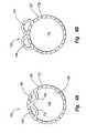
- FIG. 1is a perspective assembly view of an insertion sheath with collapsible locating lumens and a tissue puncture sealing device according to one embodiment of the present invention.
- FIG. 2is a detailed perspective view of an insertion sheath according to another embodiment of the present invention.
- FIG. 3is a detailed perspective view of an end portion of the insertion sheath from an opposite side shown in FIG. 2 .
- FIG. 4Ais a cross-sectional side view of an insertion sheath according to one embodiment of the present invention with internal collapsible locating lumens.
- FIG. 4Bis a cross-sectional side view of an insertion sheath according to another embodiment of the present invention with external locating lumens.
- FIG. 5Ais a cross-sectional side view of an insertion sheath according to another embodiment of the present invention with internal locating lumens and external wall reinforcement.
- FIG. 5Bis a cross-sectional side view of an insertion sheath according to another embodiment of the present invention with internal locating lumens and internal wall reinforcement.
- FIG. 5Cis a cross-sectional side view of an insertion sheath according to another embodiment of the present invention with internal locating lumens and internal and external wall reinforcement.
- FIG. 6is detailed perspective view of an end portion the insertion sheath of FIG. 1 with a bonded tip disassembled from the insertion sheath.
- FIG. 7Ais a perspective view of a tip portion of the insertion sheath of FIG. 1 according to another embodiment of the present invention.
- FIG. 7Bis a perspective view of a tip portion of the insertion sheath of FIG. 1 according to another embodiment of the present invention.
- FIG. 8is a cross-sectional side view a tip portion of of the insertion sheath of FIG. 1 according to another embodiment of the present invention.
- vascular proceduresare commonly performed throughout the world and require access to a bodily lumen through a puncture.
- an insertion sheath or insertion sheathis placed in the puncture to facilitate access to the lumen by one or more vascular instruments, including puncture closure devices when the vascular procedure is completed.
- the location of an artery or other lumenis indicated by a flow of blood through a puncture locator as the instrument enters the artery.
- the present inventiondescribes methods and apparatus for integrating puncture locating with the insertion sheath, while minimizing the outer diameter of the insertion sheath.
- the vascular instruments shown and described belowinclude a particular puncture sealing device, the application of the principles described herein to an insertion sheath is not limited to any specific devices.
- the principles described hereinmay be used with any vascular device, particularly vascular devices used to locate an artery. Therefore, while the description below is directed primarily to arterial procedures and the fluid referenced most often is blood flowing through an artery, the method and apparatus may be used according to principles described herein to properly position any instrument in a blood vessel or other bodily lumen.
- insertion sheathis used broadly to encompass any device used to facilitate introduction of vascular instruments into a blood vessel or other bodily lumen.
- fluidrefers to any substance whose molecules move freely past one another and that has the tendency to assume the shape of its container, including both liquids and gasses.
- a “lumen”refers to an open space, cavity, or fluid flow passage.
- the vascular insertion apparatus 100includes a vascular insertion sheath or insertion sheath 102 with a hub 104 disposed at a proximal end 105 thereof.
- the insertion sheath 102provides access to an artery or other vessel via an inside diameter 106 that is receptive of a tissue puncture sealing device 108 or other vascular instrument (e.g. as a dilator).
- the insertion sheath 102includes a primary or first flexible lumen 110 .
- the first flexible lumen 110comprises an elongated, hollow, shaft with a reinforced wall 128 .
- the reinforced wall 128is shown in cross section in FIGS. 4A-5C .
- the reinforced wall 128is preferably plastic with a filament reinforcement to provide a thin wall thickness while resisting kinking, particularly as the insertion sheath 102 is inserted into a puncture.
- the reinforced wall 128comprises a coiled filament 130 .
- the coiled filament 130extends substantially along a length of the first flexible lumen 110 as shown. However, according to other embodiments the coiled filament extends along the full length of the first flexible lumen 110 .
- the coiled filament 130may comprise any of a number of materials including, but not limited to: stainless steel, carbon fiber, aramid fiber, and Kevlar® fiber.
- the filament 130may also comprise a flat ribbon coil.
- a preformed tip 150is attached at a distal end 112 to the first flexible lumen 110 .
- the preformed tip 150is preferably flexible, but may also be rigid according to some embodiments.
- the preformed tip 150is preferably plastic and is not reinforced.
- the preformed tip 150is shown in more detail in an assembly view in FIG. 6 .
- FIG. 1includes the preformed tip 150
- other embodiments of the insertion sheath 102may not include a separately formed tip.
- another filament configurationstrengthens the reinforced wall 128 .
- the reinforced wall 128 of FIG. 2comprises a braid-reinforced wall.
- a braided filament 132provides the reinforcement.
- the braided filament 132may comprise any of the same materials listed above for the coiled filament 130 ( FIG. 1 ) including, but not limited to: stainless steel, carbon fiber, aramid fiber, and Kevlar® fiber.
- the braided filament 132may also comprise a flat ribbon braid.
- FIG. 3shows a close-up of the preformed tip 150 with the reinforced wall 128 .
- the reinforced wall 128may include other reinforcing configurations as well, and is not limited to the coiled and braided structures shown.
- the insertion sheath 102must be properly positioned in a puncture to facilitate insertion of the tissue puncture sealing device 108 or other vascular instruments.
- the insertion sheath 102is positioned with the aid of a puncture locator that is inserted through the insertion sheath and later removed as described above.
- the insertion sheath 102includes and at least one locating lumen that eliminates the need for a separate puncture locator.
- the at least one locating lumenmay comprise any of a number of shapes and configurations, several examples of which are shown and discussed below with reference to FIGS. 4A-5C . As shown in FIG.
- a first of the at least one locating lumensopens at the distal end 112 of the first flexible lumen 110 to a first inlet port 114 .
- the first inlet port 114is in fluid communication with a first outlet port 116 via a first collapsible lumen 120 ( FIG. 4A ) extending at least partially through the first flexible lumen 110 .
- a second of the at least one locating lumensopens near the distal end 112 of the first flexible lumen 110 to a second inlet port 122 .
- the second inlet port 122is spaced proximally from the first inlet port 114 to provide more precise indication of the location of the insertion sheath within a blood vessel.
- the second inlet port 122is in fluid communication with a second outlet port 124 via a second collapsible lumen 126 ( FIG. 4A ) extending at least partially though the first flexible lumen 110 .
- the second outlet port 122is spaced from the first outlet port 116 to enable a user to distinguish between fluid flows exiting through each port.
- first flexible lumen 110 of the insertion sheath 102is inserted through a percutaneous incision, through a vessel puncture, and ultimately into a blood vessel, a flow of blood will exit through the first outlet 116 when the first inlet port 114 enters the blood vessel and is exposed to a blood stream.
- the blood flow through the first outlet port 116provides a first visual indication of the location of first flexible lumen 110 .
- a second flow of bloodwill pass out of the second outlet 124 when the second inlet port 122 enters the blood vessel.
- the insertion sheath 102may be retracted after blood flow is observed through the second outlet port 124 until the blood flow therethrough ceases.
- a flow of blood through only the first outlet port 116may, according to some embodiments, indicate proper positioning of the insertion sheath 102 partially within the blood vessel. It will be appreciated by those of skill in the art having the benefit of this disclosure, however, that additional or fewer lumens having separate inlet and outlet ports may also be employed with the insertion sheath 102 as desired.
- a userBy adding at least one locating lumen to the insertion sheath 102 , a user has an advantage over the typical locating procedures that require a separate puncture locator. Providing a locating lumen to the insertion sheath 102 directly indicates insertion sheath 102 location. In addition, a shift in the insertion sheath's position is much less likely to go unnoticed according to the present invention. If the insertion sheath 102 moves out of its proper position, blood flow through the first outlet port 116 will cease, or blood will begin to flow through the second outlet port 124 . However, it may be undesirable to add to the outer diameter of the first flexible lumen 110 to provide room for the first and second collapsible lumens 120 , 126 ( FIG. 4A ).
- the first flexible lumen 110has the reinforced wall 128 shown in FIGS. 2A-2B that is thinner than conventional insertion sheath walls to accommodate at least one locator lumen without significantly increasing the outside diameter of the first flexible lumen 110 .
- FIGS. 4A-4B , FIGS. 5A-5C , and the corresponding descriptions belowdescribe several embodiments of the first flexible lumen 110 and the use one or more locator lumens.
- the reinforced wall 128is less than 0.010 inches thick. However, according to other embodiments, the reinforced wall 128 is no more than about 0.007 to 0.008 inches thick, and according to still other embodiments the reinforced wall 128 is no more than about 0.006 inches thick.
- a wall thickness of less than 0.010 inchesis less than conventional wall thicknesses for an insertion sheath, and facilitates maintaining a standard or near-standard outer diameter while adding locating lumens.
- the reinforced wall 128comprises the braided filament 132 , but the coiled filament 130 ( FIG. 1 ) or other reinforcing filaments may also be used.
- the reinforced wall 128including the reinforcing braided filament 132 , comprises the small wall thickness dimensions mentioned above.
- FIG. 4Aillustrates the first and second collapsible lumens 120 , 126 mentioned above with reference to FIG. 1 .
- the first and second collapsible lumens 120 , 126have smaller diameters than the first flexible lumen 110 .
- the first and second collapsible lumens 120 , 126comprise first and second membranes 134 , 136 , respectively, protruding from an inner diameter 138 of the first flexible lumen 110 .
- the first and second membranes 134 , 136are preferably plastic and co-extruded with the first flexible lumen 110 .
- the first and second membranes 134 , 136will generally maintain the shape shown absent any external forces.
- first and second membranes 134 , 136readily collapse in response to insertion of a vascular instrument such as the tissue puncture sealing device 108 ( FIG. 1 ) into the first flexible lumen 110 . Therefore, the insertion sheath 102 of FIG. 1 maintains a standard outer diameter consistent with a 6F or 8F size, and adds puncture locating capability by including the first and second collapsible lumens 120 , 126 .
- first and second collapsible lumens 120 , 126may be replaced by first and second external locating lumens 140 , 142 as shown in FIG. 4B .
- the first and second external locating lumens 140 , 142are preferably rigid enough to maintain the shape shown when inserted through a puncture.
- the configuration shown in FIG. 2Bfacilitates a standard 6F or 8F size for the insertion sheath 102 with a minimal addition to the outer diameter represented by the first and second external locating lumens 140 , 142 .
- the locating lumens 120 , 126 , 140 , 142 shown in FIGS. 4A-4Bmay comprise other alternative structures as well, for example the configurations shown in FIGS. 5A-5C .
- an outer diameter of the reinforced wall 128is slightly elliptical, rather than strictly circular.
- the first flexible lumen 110is generally circular, and the first and second collapsible lumens 120 , 126 are internal to the reinforced wall 128 defined by the outer diameter of the ellipse.
- An internal portion 146 of the first flexible lumen 110is not reinforced and therefore a neck 148 separating the first and second collapsible lumens 120 , 126 may buckle upon insertion of a vascular instrument into the first flexible lumen 110 and cause the first and second collapsible lumens 120 , 126 to collapse.
- the insertion of a vascular instrument into the first flexible lumen 110may have no effect on the shape of the first and second collapsible lumens 120 , 126 .
- the elliptical outer diameter shown in FIGS. 5A-5Cprovides spacing for the first and second collapsible lumens 120 , 126 with only a minimal increase in outer diameter or surface area as compared to a typical circular outer diameter.
- the reinforced wall 128does not extend around the first and second collapsible lumens 120 , 126 .
- the reinforcing filament 132encloses the generally circular first flexible lumen 110 , including the internal portion 146 .
- the reinforcing filament 132reinforces both the outer elliptical diameter and the internal portion 146 as shown in FIG. 5C .
- the first and second collapsible lumens 120 , 126may be less likely to collapse upon insertion of a vascular instrument into the first flexible lumen 110 according to the embodiments of FIGS. 5B and 5C than the embodiment of FIG. 5A because of the reinforcement along the internal portion 146 .
- the neck 148may buckle and cause the first and second collapsible lumens 120 , 126 to collapse when a sufficient internal force is applied to the first flexible lumen 110 .
- FIG. 5AThe embodiment of FIG. 5A is shown in FIG. 6 in a perspective view wherein the preformed tip 150 is disassembled from the first flexible lumen 110 .
- the preformed tipis bonded to first flexible lumen 110 at the distal end 112 .
- the preformed tip 150includes a wall thickness that varies so as to close the first and second collapsible lumens 120 , 126 at the distal end 112 .
- puncturesmay be located without the aid of a separate puncture locator, and any changes in the insertion sheath's position are readily discerned.
- a preformed tip 250includes generally circular protrusion 251 having a diameter substantially the same as or slightly greater than the diameter of the first flexible lumen 110 ( FIG. 6 ).
- the preformed tip 250 of FIG. 7Amay therefore be partially inserted into the first flexible lumen 110 ( FIG. 6 ) to form a lap joint therebetween.
- FIG. 7Bis a preformed tip 350 with a generally circular protrusion 351 and a tapered ridge 353 .
- the preformed tip 350may be partially inserted into the first flexible lumen 110 ( FIG. 6 ) to form a lap joint. Further, the tapered ridge may provide sufficient hoop stress in the first flexible lumen 110 ( FIG. 6 ) to securely attach the preformed tip 350 to the first flexible lumen 110 ( FIG. 6 ).
- a preformed tip 450may be sized to fit over the first flexible lumen 110 .
- a reverse lap jointif formed as the preformed tip 450 slides over the first flexible lumen 110 .
- the first flexible lumen 110may be stepped down to a smaller outer diameter as shown, and/or an internal diameter D of the preformed tip 450 may step up as shown. The steps in diameter for the preformed tip 450 and/or the first flexible lumen 110 facilitate a flush arrangement therebetween.
- the tissue puncture closure device 108may include a filament 154 extending from a first or proximal end 156 of the tissue puncture closure device 108 to a second or distal end 158 of the tissue puncture closure device 108 .
- the tissue puncture closure device 108also includes an anchor 160 for insertion through a tissue wall puncture, through which the filament 154 is threaded at the second end 158 of the closure device 108 .
- the sealing plug 152is slidingly attached to the filament 154 adjacent to the anchor 160 .
- the sealing plug 152may be automatically or manually tamped with a tamping tube 162 . Tamping the sealing plug 152 sandwiches the puncture between the anchor 160 and the sealing plug 152 .
- the filament 154may then be tied and/or cut, and the closure device 108 and insertion sheath 102 may be removed. Accordingly, a puncture may be located and sealed according to the present invention without the aid of a separate puncture locator.
Landscapes
- Health & Medical Sciences (AREA)
- Life Sciences & Earth Sciences (AREA)
- Biophysics (AREA)
- Pulmonology (AREA)
- Engineering & Computer Science (AREA)
- Anesthesiology (AREA)
- Biomedical Technology (AREA)
- Heart & Thoracic Surgery (AREA)
- Hematology (AREA)
- Animal Behavior & Ethology (AREA)
- General Health & Medical Sciences (AREA)
- Public Health (AREA)
- Veterinary Medicine (AREA)
- Media Introduction/Drainage Providing Device (AREA)
- Surgical Instruments (AREA)
Abstract
Description
Claims (28)
Priority Applications (1)
| Application Number | Priority Date | Filing Date | Title |
|---|---|---|---|
| US10/827,714US7648493B2 (en) | 2004-04-20 | 2004-04-20 | Method and apparatus for locating vascular punctures |
Applications Claiming Priority (1)
| Application Number | Priority Date | Filing Date | Title |
|---|---|---|---|
| US10/827,714US7648493B2 (en) | 2004-04-20 | 2004-04-20 | Method and apparatus for locating vascular punctures |
Publications (2)
| Publication Number | Publication Date |
|---|---|
| US20050234396A1 US20050234396A1 (en) | 2005-10-20 |
| US7648493B2true US7648493B2 (en) | 2010-01-19 |
Family
ID=35097213
Family Applications (1)
| Application Number | Title | Priority Date | Filing Date |
|---|---|---|---|
| US10/827,714Active2026-11-05US7648493B2 (en) | 2004-04-20 | 2004-04-20 | Method and apparatus for locating vascular punctures |
Country Status (1)
| Country | Link |
|---|---|
| US (1) | US7648493B2 (en) |
Cited By (18)
| Publication number | Priority date | Publication date | Assignee | Title |
|---|---|---|---|---|
| US20070049967A1 (en)* | 2005-08-24 | 2007-03-01 | Sibbitt Wilmer L Jr | Vascular closure methods and apparatuses |
| US20070049968A1 (en)* | 2005-08-24 | 2007-03-01 | Sibbitt Wilmer L Jr | Vascular opening edge eversion methods and apparatuses |
| US20070203506A1 (en)* | 2005-08-24 | 2007-08-30 | Sibbitt Wilmer L Jr | Vascular closure methods and apparatuses |
| US20090254119A1 (en)* | 2005-08-24 | 2009-10-08 | Avasca Medical Inc. | Vascular Closure Methods and Apparatuses |
| USD630733S1 (en)* | 2008-10-29 | 2011-01-11 | Astra Tech Ab | Catheter with catheter sleeve |
| US9149276B2 (en) | 2011-03-21 | 2015-10-06 | Abbott Cardiovascular Systems, Inc. | Clip and deployment apparatus for tissue closure |
| US9414822B2 (en) | 2011-05-19 | 2016-08-16 | Abbott Cardiovascular Systems, Inc. | Tissue eversion apparatus and tissue closure device and methods for use thereof |
| US9554785B2 (en) | 2012-12-21 | 2017-01-31 | Essential Medical, Inc. | Vascular locating systems and methods of use |
| US10154835B2 (en) | 2013-05-09 | 2018-12-18 | Essential Medical, Inc. | Vascular closure device with conforming plug member |
| US10383611B2 (en) | 2011-10-25 | 2019-08-20 | Essential Medical, Inc. | Instrument and methods for surgically closing percutaneous punctures |
| US11350919B2 (en) | 2019-02-19 | 2022-06-07 | Teleflex Life Sciences Limited | Puncture locating system with blood pulsation indicator |
| US11364024B2 (en) | 2013-12-23 | 2022-06-21 | Teleflex Life Sciences Limited | Vascular closure device |
| CN114768052A (en)* | 2016-07-06 | 2022-07-22 | 阿比奥梅德欧洲股份有限公司 | Introducer sheath for vascular access |
| US11419592B2 (en) | 2013-03-15 | 2022-08-23 | Teleflex Life Sciences Limited | Vascular closure devices and methods of use |
| US11576663B2 (en) | 2015-06-26 | 2023-02-14 | Teleflex Life Sciences Limited | Vascular closure device with removable guide member |
| US12285160B2 (en) | 2012-07-19 | 2025-04-29 | Teleflex Life Sciences Llc | Multi-lumen tamper tube |
| US12383246B2 (en) | 2020-10-12 | 2025-08-12 | Abbott Cardiovascular Systems, Inc. | Vessel closure device with improved safety and tract hemostasis |
| US12390249B2 (en) | 2020-07-31 | 2025-08-19 | Teleflex Life Sciences Llc | Access sheath with valve assembly |
Families Citing this family (10)
| Publication number | Priority date | Publication date | Assignee | Title |
|---|---|---|---|---|
| WO2006111945A2 (en)* | 2005-04-18 | 2006-10-26 | Salviac Limited | A retrieval catheter |
| EP1987788B1 (en)* | 2006-02-21 | 2016-07-20 | Olympus Corporation | Endoscope system and medical instrument |
| US9456816B2 (en) | 2007-09-12 | 2016-10-04 | Transluminal Technologies, Llc | Closure device, deployment apparatus, and method of deploying a closure device |
| US8876861B2 (en) | 2007-09-12 | 2014-11-04 | Transluminal Technologies, Inc. | Closure device, deployment apparatus, and method of deploying a closure device |
| JP5426553B2 (en) | 2007-09-12 | 2014-02-26 | トランスルミナル テクノロジーズ リミテッド ライアビリティー カンパニー | Closure device, placement device, and method of placing a closure device |
| EP2464296B1 (en) | 2009-08-14 | 2018-09-19 | Terumo Puerto Rico L.L.C. | Carrier tube for vascular closure device |
| AU2011326525B2 (en) | 2010-11-09 | 2015-06-18 | Transluminal Technologies, Llc | Specially designed magnesium-aluminum alloys and medical uses thereof in a hemodynamic environment |
| US20120239061A1 (en)* | 2011-03-15 | 2012-09-20 | Mathur Sandip V | Endoscopic full thickness gastric reduction apparatus and method |
| EP3007631A4 (en)* | 2013-06-11 | 2016-11-16 | Promed Inc | Improved vessel access closure |
| DE102020214618A1 (en)* | 2020-11-19 | 2022-05-19 | B. Braun Melsungen Aktiengesellschaft | Soft elastic catheter tip |
Citations (26)
| Publication number | Priority date | Publication date | Assignee | Title |
|---|---|---|---|---|
| US4317445A (en) | 1980-03-31 | 1982-03-02 | Baxter Travenol Laboratories, Inc. | Catheter insertion unit with separate flashback indication for the cannula |
| US4406656A (en)* | 1981-06-01 | 1983-09-27 | Brack Gillium Hattler | Venous catheter having collapsible multi-lumens |
| US5282827A (en) | 1991-11-08 | 1994-02-01 | Kensey Nash Corporation | Hemostatic puncture closure system and method of use |
| US5290310A (en) | 1991-10-30 | 1994-03-01 | Howmedica, Inc. | Hemostatic implant introducer |
| US5292332A (en) | 1992-07-27 | 1994-03-08 | Lee Benjamin I | Methods and device for percutanceous sealing of arterial puncture sites |
| US5411520A (en) | 1991-11-08 | 1995-05-02 | Kensey Nash Corporation | Hemostatic vessel puncture closure system utilizing a plug located within the puncture tract spaced from the vessel, and method of use |
| US5431639A (en) | 1993-08-12 | 1995-07-11 | Boston Scientific Corporation | Treating wounds caused by medical procedures |
| US5437631A (en) | 1990-09-21 | 1995-08-01 | Datascope Investment Corp. | Percutaneous introducer set and method for sealing puncture wounds |
| US5443481A (en) | 1992-07-27 | 1995-08-22 | Lee; Benjamin I. | Methods and device for percutaneous sealing of arterial puncture sites |
| US5486195A (en) | 1993-07-26 | 1996-01-23 | Myers; Gene | Method and apparatus for arteriotomy closure |
| US5613974A (en) | 1992-12-10 | 1997-03-25 | Perclose, Inc. | Apparatus and method for vascular closure |
| US5643318A (en)* | 1994-03-31 | 1997-07-01 | Boston Scientific Corporation | Vascular plug with vessel locator |
| US5645566A (en) | 1995-09-15 | 1997-07-08 | Sub Q Inc. | Apparatus and method for percutaneous sealing of blood vessel punctures |
| US5695457A (en)* | 1994-07-28 | 1997-12-09 | Heartport, Inc. | Cardioplegia catheter system |
| US5755727A (en) | 1995-06-02 | 1998-05-26 | Cardiologics L.L.C. | Method device for locating and sealing a blood vessel |
| US5810810A (en) | 1992-04-23 | 1998-09-22 | Scimed Life Systems, Inc. | Apparatus and method for sealing vascular punctures |
| US5814065A (en) | 1996-02-09 | 1998-09-29 | Cordis Corporation | Suture delivery tool |
| US5868717A (en)* | 1996-04-10 | 1999-02-09 | Biolink Corporation | Dual-lumen catheter and method of use |
| US6004310A (en)* | 1998-06-17 | 1999-12-21 | Target Therapeutics, Inc. | Multilumen catheter shaft with reinforcement |
| US6022372A (en) | 1997-02-11 | 2000-02-08 | X-Site, L.L.C. | Arterial stapling device |
| US6090130A (en) | 1991-11-08 | 2000-07-18 | Kensey Nash Corporation | Hemostatic puncture closure system including blood vessel locator and method of use |
| US6162192A (en) | 1998-05-01 | 2000-12-19 | Sub Q, Inc. | System and method for facilitating hemostasis of blood vessel punctures with absorbable sponge |
| US6193670B1 (en) | 1997-02-14 | 2001-02-27 | Tricardia, Llc | Hemostatic agent delivery device having built-in pressure sensor |
| US6231561B1 (en) | 1999-09-20 | 2001-05-15 | Appriva Medical, Inc. | Method and apparatus for closing a body lumen |
| US6270477B1 (en)* | 1996-05-20 | 2001-08-07 | Percusurge, Inc. | Catheter for emboli containment |
| US6682489B2 (en) | 2001-01-12 | 2004-01-27 | Radi Medical Systems Ab | Technique to confirm correct positioning of arterial wall sealing device |
- 2004
- 2004-04-20USUS10/827,714patent/US7648493B2/enactiveActive
Patent Citations (29)
| Publication number | Priority date | Publication date | Assignee | Title |
|---|---|---|---|---|
| US4317445A (en) | 1980-03-31 | 1982-03-02 | Baxter Travenol Laboratories, Inc. | Catheter insertion unit with separate flashback indication for the cannula |
| US4406656A (en)* | 1981-06-01 | 1983-09-27 | Brack Gillium Hattler | Venous catheter having collapsible multi-lumens |
| US5437631A (en) | 1990-09-21 | 1995-08-01 | Datascope Investment Corp. | Percutaneous introducer set and method for sealing puncture wounds |
| US5290310A (en) | 1991-10-30 | 1994-03-01 | Howmedica, Inc. | Hemostatic implant introducer |
| US5707393A (en) | 1991-11-08 | 1998-01-13 | Kensey Nash Corporation | Hemostatic puncture closure system and method of use |
| US5282827A (en) | 1991-11-08 | 1994-02-01 | Kensey Nash Corporation | Hemostatic puncture closure system and method of use |
| US5935147A (en) | 1991-11-08 | 1999-08-10 | Kensey Nash Corporation | Hemostatic puncture closure system and method of use |
| US6179863B1 (en) | 1991-11-08 | 2001-01-30 | Kensey Nash Corporation | Hemostatic puncture closure system and method of use |
| US6090130A (en) | 1991-11-08 | 2000-07-18 | Kensey Nash Corporation | Hemostatic puncture closure system including blood vessel locator and method of use |
| US5411520A (en) | 1991-11-08 | 1995-05-02 | Kensey Nash Corporation | Hemostatic vessel puncture closure system utilizing a plug located within the puncture tract spaced from the vessel, and method of use |
| US5810810A (en) | 1992-04-23 | 1998-09-22 | Scimed Life Systems, Inc. | Apparatus and method for sealing vascular punctures |
| US5443481A (en) | 1992-07-27 | 1995-08-22 | Lee; Benjamin I. | Methods and device for percutaneous sealing of arterial puncture sites |
| US5292332A (en) | 1992-07-27 | 1994-03-08 | Lee Benjamin I | Methods and device for percutanceous sealing of arterial puncture sites |
| US5613974A (en) | 1992-12-10 | 1997-03-25 | Perclose, Inc. | Apparatus and method for vascular closure |
| US5486195A (en) | 1993-07-26 | 1996-01-23 | Myers; Gene | Method and apparatus for arteriotomy closure |
| US5431639A (en) | 1993-08-12 | 1995-07-11 | Boston Scientific Corporation | Treating wounds caused by medical procedures |
| US5643318A (en)* | 1994-03-31 | 1997-07-01 | Boston Scientific Corporation | Vascular plug with vessel locator |
| US5695457A (en)* | 1994-07-28 | 1997-12-09 | Heartport, Inc. | Cardioplegia catheter system |
| US5755727A (en) | 1995-06-02 | 1998-05-26 | Cardiologics L.L.C. | Method device for locating and sealing a blood vessel |
| US5645566A (en) | 1995-09-15 | 1997-07-08 | Sub Q Inc. | Apparatus and method for percutaneous sealing of blood vessel punctures |
| US5814065A (en) | 1996-02-09 | 1998-09-29 | Cordis Corporation | Suture delivery tool |
| US5868717A (en)* | 1996-04-10 | 1999-02-09 | Biolink Corporation | Dual-lumen catheter and method of use |
| US6270477B1 (en)* | 1996-05-20 | 2001-08-07 | Percusurge, Inc. | Catheter for emboli containment |
| US6022372A (en) | 1997-02-11 | 2000-02-08 | X-Site, L.L.C. | Arterial stapling device |
| US6193670B1 (en) | 1997-02-14 | 2001-02-27 | Tricardia, Llc | Hemostatic agent delivery device having built-in pressure sensor |
| US6162192A (en) | 1998-05-01 | 2000-12-19 | Sub Q, Inc. | System and method for facilitating hemostasis of blood vessel punctures with absorbable sponge |
| US6004310A (en)* | 1998-06-17 | 1999-12-21 | Target Therapeutics, Inc. | Multilumen catheter shaft with reinforcement |
| US6231561B1 (en) | 1999-09-20 | 2001-05-15 | Appriva Medical, Inc. | Method and apparatus for closing a body lumen |
| US6682489B2 (en) | 2001-01-12 | 2004-01-27 | Radi Medical Systems Ab | Technique to confirm correct positioning of arterial wall sealing device |
Cited By (31)
| Publication number | Priority date | Publication date | Assignee | Title |
|---|---|---|---|---|
| US9456811B2 (en) | 2005-08-24 | 2016-10-04 | Abbott Vascular Inc. | Vascular closure methods and apparatuses |
| US20070049968A1 (en)* | 2005-08-24 | 2007-03-01 | Sibbitt Wilmer L Jr | Vascular opening edge eversion methods and apparatuses |
| US20070203506A1 (en)* | 2005-08-24 | 2007-08-30 | Sibbitt Wilmer L Jr | Vascular closure methods and apparatuses |
| US20090254119A1 (en)* | 2005-08-24 | 2009-10-08 | Avasca Medical Inc. | Vascular Closure Methods and Apparatuses |
| US20100130965A1 (en)* | 2005-08-24 | 2010-05-27 | Abbott Vascular Inc. | Redundant Tissue Closure Methods and Apparatuses |
| US8048108B2 (en)* | 2005-08-24 | 2011-11-01 | Abbott Vascular Inc. | Vascular closure methods and apparatuses |
| US8758397B2 (en) | 2005-08-24 | 2014-06-24 | Abbott Vascular Inc. | Vascular closure methods and apparatuses |
| US8920442B2 (en) | 2005-08-24 | 2014-12-30 | Abbott Vascular Inc. | Vascular opening edge eversion methods and apparatuses |
| US8932324B2 (en) | 2005-08-24 | 2015-01-13 | Abbott Vascular Inc. | Redundant tissue closure methods and apparatuses |
| US20070049967A1 (en)* | 2005-08-24 | 2007-03-01 | Sibbitt Wilmer L Jr | Vascular closure methods and apparatuses |
| USD630733S1 (en)* | 2008-10-29 | 2011-01-11 | Astra Tech Ab | Catheter with catheter sleeve |
| US9149276B2 (en) | 2011-03-21 | 2015-10-06 | Abbott Cardiovascular Systems, Inc. | Clip and deployment apparatus for tissue closure |
| US9414822B2 (en) | 2011-05-19 | 2016-08-16 | Abbott Cardiovascular Systems, Inc. | Tissue eversion apparatus and tissue closure device and methods for use thereof |
| US11589855B2 (en) | 2011-10-25 | 2023-02-28 | Teleflex Life Sciences Limited | Instrument and methods for surgically closing percutaneous punctures |
| US10383611B2 (en) | 2011-10-25 | 2019-08-20 | Essential Medical, Inc. | Instrument and methods for surgically closing percutaneous punctures |
| US10485524B2 (en) | 2011-10-25 | 2019-11-26 | Essential Medical, Inc. | Instrument and methods for surgically closing percutaneous punctures |
| US12285160B2 (en) | 2012-07-19 | 2025-04-29 | Teleflex Life Sciences Llc | Multi-lumen tamper tube |
| US9554785B2 (en) | 2012-12-21 | 2017-01-31 | Essential Medical, Inc. | Vascular locating systems and methods of use |
| US10182804B2 (en) | 2012-12-21 | 2019-01-22 | Essential Medical, Inc. | Vascular locating systems and methods of use |
| US10835225B2 (en) | 2012-12-21 | 2020-11-17 | Arrow International, Inc. | Vascular locating systems and methods of use |
| US11759191B2 (en) | 2012-12-21 | 2023-09-19 | Teleflex Life Sciences Limited | Vascular locating systems and methods of use |
| US12426865B2 (en) | 2013-03-15 | 2025-09-30 | Teleflex Life Sciences Llc | Vascular closure devices and methods of use |
| US11419592B2 (en) | 2013-03-15 | 2022-08-23 | Teleflex Life Sciences Limited | Vascular closure devices and methods of use |
| US10154835B2 (en) | 2013-05-09 | 2018-12-18 | Essential Medical, Inc. | Vascular closure device with conforming plug member |
| US11779320B2 (en) | 2013-12-23 | 2023-10-10 | Teleflex Life Sciences Limited | Vascular closure device |
| US11364024B2 (en) | 2013-12-23 | 2022-06-21 | Teleflex Life Sciences Limited | Vascular closure device |
| US11576663B2 (en) | 2015-06-26 | 2023-02-14 | Teleflex Life Sciences Limited | Vascular closure device with removable guide member |
| CN114768052A (en)* | 2016-07-06 | 2022-07-22 | 阿比奥梅德欧洲股份有限公司 | Introducer sheath for vascular access |
| US11350919B2 (en) | 2019-02-19 | 2022-06-07 | Teleflex Life Sciences Limited | Puncture locating system with blood pulsation indicator |
| US12390249B2 (en) | 2020-07-31 | 2025-08-19 | Teleflex Life Sciences Llc | Access sheath with valve assembly |
| US12383246B2 (en) | 2020-10-12 | 2025-08-12 | Abbott Cardiovascular Systems, Inc. | Vessel closure device with improved safety and tract hemostasis |
Also Published As
| Publication number | Publication date |
|---|---|
| US20050234396A1 (en) | 2005-10-20 |
Similar Documents
| Publication | Publication Date | Title |
|---|---|---|
| US7648493B2 (en) | Method and apparatus for locating vascular punctures | |
| US6159198A (en) | Introducer system | |
| US20030199850A1 (en) | Orthogonal arterial catheter | |
| US4650472A (en) | Apparatus and method for effecting percutaneous catheterization of a blood vessel using a small gauge introducer needle | |
| EP0664687B2 (en) | Vessel position locating device | |
| US6024747A (en) | Device and method for suturing blood vessels and the like | |
| EP2709712B1 (en) | Sheath-dilator system | |
| CA2196043C (en) | Flattened collapsible vascular catheter | |
| CA2608521C (en) | Puncture locating device | |
| EP1598016A2 (en) | Guide wire with releasable barb anchor | |
| US20040106891A1 (en) | Localizing needle with fluid delivery | |
| US20050085773A1 (en) | Method and apparatus for locating vascular punctures | |
| JP2005537855A (en) | Combined introducer and hemostasis valve and method of using the same | |
| JP2010524546A (en) | Introducer adapter | |
| WO2014164008A1 (en) | Temporary sealing device with blood flashback for vessel location | |
| EP2680911B1 (en) | Vascular needle system | |
| JP2010142655A (en) | Surgical access apparatus | |
| NZ243696A (en) | Catheter with segments having different flexibility | |
| JPH0299070A (en) | Intravenous catheter having automatic positioning needle protective part | |
| JP5997159B2 (en) | Dilator, introducer assembly, and medical device | |
| US10588659B2 (en) | Intravascular memory metal puncture system and use thereof | |
| EP3927258B1 (en) | Puncture locating system with blood pulsation indicator | |
| US11992634B2 (en) | Arterial access needle with proximal port | |
| US6610045B2 (en) | Orthogonal arterial catheter | |
| CN112702945A (en) | Apparatus and method for sensor deployment and fixation |
Legal Events
| Date | Code | Title | Description |
|---|---|---|---|
| AS | Assignment | Owner name:ST. JUDE MEDICAL PUERTO RICO B.V., NETHERLANDS Free format text:ASSIGNMENT OF ASSIGNORS INTEREST;ASSIGNORS:FORSBERG, ANDREW THOMAS;PAPROCKI, LORAN;REEL/FRAME:015463/0277 Effective date:20040510 | |
| AS | Assignment | Owner name:ST. JUDE MEDICAL PUERTO RICO LLC, PUERTO RICO Free format text:ACQUISITION;ASSIGNOR:ST. JUDE MEDICAL PUERTO RICO B.V.;REEL/FRAME:021998/0591 Effective date:20071228 Owner name:ST. JUDE MEDICAL PUERTO RICO LLC,PUERTO RICO Free format text:ACQUISITION;ASSIGNOR:ST. JUDE MEDICAL PUERTO RICO B.V.;REEL/FRAME:021998/0591 Effective date:20071228 | |
| STCF | Information on status: patent grant | Free format text:PATENTED CASE | |
| FPAY | Fee payment | Year of fee payment:4 | |
| AS | Assignment | Owner name:TERUMO PUERTO RICO, L.L.C., PUERTO RICO Free format text:ASSIGNMENT OF ASSIGNORS INTEREST;ASSIGNOR:ST. JUDE MEDICAL PUERTO RICO LLC;REEL/FRAME:041520/0883 Effective date:20170120 | |
| FPAY | Fee payment | Year of fee payment:8 | |
| MAFP | Maintenance fee payment | Free format text:PAYMENT OF MAINTENANCE FEE, 12TH YEAR, LARGE ENTITY (ORIGINAL EVENT CODE: M1553); ENTITY STATUS OF PATENT OWNER: LARGE ENTITY Year of fee payment:12 |