US7646969B2 - Camera snubber assembly - Google Patents
Camera snubber assemblyDownload PDFInfo
- Publication number
- US7646969B2 US7646969B2US11/268,849US26884905AUS7646969B2US 7646969 B2US7646969 B2US 7646969B2US 26884905 AUS26884905 AUS 26884905AUS 7646969 B2US7646969 B2US 7646969B2
- Authority
- US
- United States
- Prior art keywords
- stage
- assembly
- snubber assembly
- snubber
- recited
- Prior art date
- Legal status (The legal status is an assumption and is not a legal conclusion. Google has not performed a legal analysis and makes no representation as to the accuracy of the status listed.)
- Active, expires
Links
Images


Classifications
- G—PHYSICS
- G03—PHOTOGRAPHY; CINEMATOGRAPHY; ANALOGOUS TECHNIQUES USING WAVES OTHER THAN OPTICAL WAVES; ELECTROGRAPHY; HOLOGRAPHY
- G03B—APPARATUS OR ARRANGEMENTS FOR TAKING PHOTOGRAPHS OR FOR PROJECTING OR VIEWING THEM; APPARATUS OR ARRANGEMENTS EMPLOYING ANALOGOUS TECHNIQUES USING WAVES OTHER THAN OPTICAL WAVES; ACCESSORIES THEREFOR
- G03B3/00—Focusing arrangements of general interest for cameras, projectors or printers
- G03B3/02—Focusing arrangements of general interest for cameras, projectors or printers moving lens along baseboard
- G—PHYSICS
- G02—OPTICS
- G02B—OPTICAL ELEMENTS, SYSTEMS OR APPARATUS
- G02B7/00—Mountings, adjusting means, or light-tight connections, for optical elements
- G02B7/003—Alignment of optical elements
- G—PHYSICS
- G02—OPTICS
- G02B—OPTICAL ELEMENTS, SYSTEMS OR APPARATUS
- G02B7/00—Mountings, adjusting means, or light-tight connections, for optical elements
- G02B7/02—Mountings, adjusting means, or light-tight connections, for optical elements for lenses
- G02B7/023—Mountings, adjusting means, or light-tight connections, for optical elements for lenses permitting adjustment
- G—PHYSICS
- G03—PHOTOGRAPHY; CINEMATOGRAPHY; ANALOGOUS TECHNIQUES USING WAVES OTHER THAN OPTICAL WAVES; ELECTROGRAPHY; HOLOGRAPHY
- G03B—APPARATUS OR ARRANGEMENTS FOR TAKING PHOTOGRAPHS OR FOR PROJECTING OR VIEWING THEM; APPARATUS OR ARRANGEMENTS EMPLOYING ANALOGOUS TECHNIQUES USING WAVES OTHER THAN OPTICAL WAVES; ACCESSORIES THEREFOR
- G03B17/00—Details of cameras or camera bodies; Accessories therefor
- G03B17/02—Bodies
- H—ELECTRICITY
- H04—ELECTRIC COMMUNICATION TECHNIQUE
- H04N—PICTORIAL COMMUNICATION, e.g. TELEVISION
- H04N23/00—Cameras or camera modules comprising electronic image sensors; Control thereof
- H04N23/50—Constructional details
Definitions
- the present inventionrelates generally to cameras.
- the present inventionrelates more particularly to a snubber assembly for limiting the motion of optical elements in a miniature camera, such as a miniature camera that is suitable for use in a cellular telephone.
- Miniature camerasare well known. Miniature cameras are widely used in contemporary cellular telephones. They are also used in other devices, such as laptop computers and personal digital assistants (PDAs). Miniature cameras can even be used as stand alone devices for such applications as security and surveillance.
- PDAspersonal digital assistants
- Contemporary miniature camerassuch as those used in cellular telephones, are fixed focus cameras. That is, the focus of the cameras is preset. The camera has a small enough aperture so as to provide sufficient depth of field such that focus is generally acceptable over a wide range of distances. However, such stopping down of the camera severely limits it's use in low light conditions.
- Stopping downalso limits resolution since it tends to inhibit the use of higher pixel count imagers. As those skilled in the art will appreciate, larger apertures allow higher imager pixel counts, but require the use of variable focus.
- movable opticssuffer from inherent disadvantages. Foremost among these disadvantages is the size of the mechanisms required to effect and control movement of the movable optics. For example, the structures used to control the movement of optics in larger cameras are simply too large for use in many miniature cameras. As such, it is desirable to provide miniature structures for controlling motion in miniature cameras.
- a method and system for controlling, i.e., limiting, the motion of miniature components, such as the optics of a cameraare disclosed.
- the systemcan comprise a stage and a snubber assembly for controlling the motion of the stage in six degrees of freedom.
- Camera opticscan be attached to the stage to facilitate focusing and/or zooming.
- the stagecan move freely in one degree of freedom within a limited range of motion.
- the movement of the stagecan be used for moving optics so as to effect focus and/or zoom, for example.
- the snubber assemblycan readily permit movement in one translational degree of freedom while substantially limiting motion in the other five degrees of freedom. This is accomplished in a manner that facilitates focusing and/or zooming of a camera while inhibiting misalignment of the optics and while also providing some protection against shock and vibration.
- Such motion controlcan be achieved while mitigating the costs associated with precision manufacturing of the snubber assembly. More particularly, the precision with which manufacturing of the snubber assembly is performed can be reduced by relying upon physical features of a stage assembly to facilitate precise positioning of physical features of the snubber assembly. That is, positioning of at least some features of the snubber assembly are dependent upon corresponding features of the stage assembly such that desirable alignment of the snubber assembly with respect to the stage assembly results.
- mesas of the snubber assemblyabut stationary or fixed portions of the stage assembly so as to define, at least in part, one or more horizontal gaps between the stage and the snubber assembly.
- the size of these horizontal gapsdetermines the limits of horizontal movement of the stage.
- shims of the snubber assemblyabut the fixed portion of the stage assembly so as to define, at least in part, one or more vertical gaps between the stage and the snubber assembly.
- the size of these vertical gapsdetermines the limits of vertical movement of the stage.
- Undesirable rotations of the stagescan also be limited by the snubber assembly of the present invention.
- Pitching motionrotation about the horizontal or lateral axis, which is orthogonal to the direction of travel
- yaw motionrotation about a vertical axis
- roll motionrotation about an axis along the direction of travel
- the snubber assemblyinhibits vertical motion of the front and back ends of the stage, lateral motion of the front and back ends of the stage, and vertical motion of the sides of the stage, these three rotations are substantially inhibited.
- smaller features of the snubber assemblyare manufactured with higher tolerances, while larger features of the snubber assembly can be manufactured with lower tolerances. It is not necessary to manufacture larger features of the snubber assembly with higher tolerances and thus manufacturing costs are therefore substantially reduced.
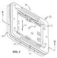
- FIG. 1is perspective top view of a stage and snubber assembly according to an exemplary embodiment of the present invention
- FIG. 2is a top perspective cross-sectional view of the stage and snubber assembly taken along line 2 of FIG. 1 ;
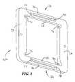
- FIG. 3is an outboard perspective view of a snubber portion of FIG. 1 ;
- FIG. 4is an inboard perspective view of the snubber portion of FIG. 3 ;
- FIG. 5is a top or bottom (both are identical) perspective view of the stage assembly of FIG. 1 ;
- FIG. 6is an enlarged fragmentary view of the interface of the top snubber, the bottom snubber, and the stage, taken within line 5 of FIG. 2 .
- a method and system for defining the motion of a stageis disclosed.
- the stageis suitable for mounting camera optics upon.
- focus and/or zoom lensescan be mounted to the stage.
- motion of the stage in six degrees of freedomis controlled. More particularly, motion in five degrees of freedom is substantially limited, while motion in one translational degree is freedom is facilitated.
- translational motion in two degrees of freedomcan be limited to approximately 10 microns
- rotational motion in three degrees of freedomcan be limited to approximately 0.1 degrees
- translational motion in one degree of freedom in excess of one millimetercan be facilitated.
- the stagecan be permitted to translate along one axis sufficiently so as to effect focusing and/or zooming, while not being permitted to translate sufficiently along other axes or to rotate about any axis sufficiently so as to effect misalignment of the optics to a degree that would substantially degrade performance of the camera.
- the snubber assembly of the present inventioncan be configured so as to only effect motion control when the stage is caused to move outside of a set of predefined ranges. That is, the snubber assembly can be configured such that it has no effect until the stage experiences a shock or abnormal operation that would otherwise cause it to move in an undesirable manner. When this happens, the snubber assembly can then restrict motion of the stage to within the desired ranges, so as to prevent the misalignment of optics, for example. Thus, during normal operation, the snubber assembly can have little or no effect.
- One way to make a snubber assembly that limits movement of a stageis to use close (precise) tolerances to assure that all features of the snubber assembly are properly located.
- close (precise) tolerancesto assure that all features of the snubber assembly are properly located.
- such construction of the snubber assemblyrequires that the comparatively large structures thereof be manufactured with the same close tolerances as the comparatively small structures.
- it is comparatively easy to manufacture smaller structures with such close tolerancesit becomes increasingly difficult to do so as the size of the structures increases. That is, deviations from desired dimensions tend to accumulate across larger distances, making it difficult to maintain close tolerances.
- a different approachresults in a snubber that precisely limits the motion of a stage.
- critical gap dimensionsare obtained by manufacturing only selected small structures of the snubber assembly with comparatively higher precision, while manufacturing the rest (particularly the larger dimensions) of the snubber assembly with substantially lower precision. Because the larger dimensions are manufactured with lower precision, the positions of the smaller structures of the snubber assembly are not precise.
- stage assembly 10(better shown in FIG. 5 ) is sandwiched between two portions, 11 and 12 (better shown in FIGS. 3 and 4 ), of a snubber assembly 13 , according to one embodiment of the present invention.
- the stage assembly 10 and the snubber assembly 13can be generally planar structures, formed from silicon, for instance.
- Stage assembly 10 and/or snubber assembly 13can alternatively be formed from another material, such as plastic or metal.
- both the stage assembly 10 and the snubber assembly 13can be formed from either plastic or silicon or any other desired material or combination of materials.
- Stage assembly 10comprises a stage 41 that moves back-and-forth, so as to facilitate movement of optics for focusing and/or zooming, for example.
- Stage assembly 10further comprises a frame 42 that generally surrounds stage 41 (as best seen in FIG. 5 ).
- Frame 42is fixed in position with respect to snubber assembly 13 and thus does not move.
- Arrow 16shows the back-and-forth directions of motion of stage 41 with respect to frame 42 (better shown in FIG. 5 ) and with respect to snubber assembly 13 .
- Snubber assembly 13facilitates such back-and-forth motion of stage 41 while substantially inhibiting all other motions of stage 41 .
- each portion 11 , 12 of snubber assembly 13can be a generally planar and generally rectangular structure.
- Snubber assembly 13can comprise two biasing members 31 and 32 that function as springs to bias two sides 33 and 34 outwardly, so as to cause them to contact portions (surfaces 56 and 57 as shown in FIG. 6 ) of frame 42 in a manner that advantageously positions critical features of snubber assembly 13 , as discussed in detail below.
- the inherent resiliency of snubber assembly 13can effect such biasing.
- Each biasing member 31 , 32can comprise an inboard member 35 , an outboard member 36 , and two side members 37 and 38 that are configure to cooperate so as to provide spring tension that moves the sides 33 and 34 outwardly after sides 33 , 34 have been pushed inwardly (such as when stage assembly 10 is being installed therebetween). That is, the rectangle defined by an inboard member 35 , an outboard member 36 , and two side members 37 and 38 can deform so as to define a parallelogram that provides spring tension.
- Each portion 11 , 12 of snubber assembly 13further comprises structural features that cooperate with stage assembly 10 to define tolerances or spacings between snubber assembly 13 and stage 41 , as discussed in detail with reference to FIG. 6 below.
- each portion 11 , 12 of snubber assembly 13may have formed upon an inboard (snubber assembly 10 contacting) surface thereof a plurality of mesas 51 , shims 61 , and stops 58 , the functions of which are discussed in detail with reference to FIG. 6 below.
- mesasare shown formed upon both of the snubber assemblies, mesas may alternatively be formed upon only one of the snubber assemblies.
- Mesascan be formed upon both snubber assemblies so as to maintain symmetry (so as to allow a single part to be capable of being used as either an upper snubber or a lower snubber. However, such symmetry is not a requirement. Therefore, a single mesa (which will generally have approximately twice the height of the mesas shown in FIG. 4 ) can replace each complimentary pair of mesas.
- stage assembly 10comprises a movable portion or stage 41 and a fixed portion or frame 42 .
- Stage 41can be a generally planar, generally rectangular structure. Optics are attachable, either directly or indirectly, to stage 41 .
- Stage 41can move in response to a motor or actuator, such as to effect focusing and/or zooming.
- a motor or actuatorsuch as to effect focusing and/or zooming.
- an optics assembly(not shown) can be attached to stage 41 via apertures 43 a - 43 d.
- Frame 42can similarly be a generally planar and generally rectangular structure that can substantially surround a periphery of stage 41 .
- Frame 42can be movably attached to stage 41 via flexure assemblies 45 and 46 .
- Flexure assemblies 45 and 46can preferentially facilitate movement of stage 41 in one desired translational degree of freedom, i.e., in the back-and-forth directions of arrow 16 of FIG. 1 .
- Snubber assembly 13can limit movement of stage 41 that is beyond the one desired translation degree of freedom.
- Stage 41can be of any desired shape and/or configuration.
- Stage assembly 10can be formed monolithicly, such as via the etching or milling of a single piece of silicon or other material.
- snubber assembly 13can also be formed monolithicly.
- stage assembly 10 and/or snubber assembly 13can be formed in any other desired manner using any desired material. Indeed, the reduced precision needed by snubber assembly 13 according to one aspect of the present invention allows snubber assembly 13 to be formed of plastic using low a precision manufacturing process.
- Snubber assembly 13defines limits to movement of stage 41 , so as to inhibit movement in five other degrees of freedom for which it is desirable to restrict movement of stage 41 .
- Such limitations on the movement of stage 41tend to maintain desired alignment of components, such as optics.
- the limitationsare also desirable, for example, in the event of shock or vibration that would other cause stage 41 to move in a manner that may cause damage to itself or other components, e.g., lenses of a camera.
- the stage, and consequently the camera opticscan be permitted to move in a manner that facilitates desired functionality, e.g., focusing and/or zooming, while also being restrained in a manner that mitigates undesirable malfunctioning (misalignment of optics) and damage.
- stage assembly 10 and snubber assembly 13that limit motion of stage 41 in five degrees of freedom while facilitating substantially more motion in a sixth degree of freedom (as indicated by arrow 16 in FIG. 1 ) are shown.
- Each portion 11 , 12 of snubber assembly 13comprises features such as mesas 51 , 52 , shims 53 , 54 , and stops 58 , 59 that define limits to the movement of stage 41 in five degrees of freedom while permitting unrestricted movement of stage 41 in one degree of freedom.
- Mesas 51 , 52 , shims 53 , 54 , and stops 58 , 59are formed precisely. They are also precisely positioned by keying to or abutting precisely formed portions of frame 42 , so that they are, in-turn, precisely positioned themselves and are thus suitable for defining limits to the movement of stage 41 .
- stage 41limits to the movement of stage 41 can be defined with greater precision than the precision with which the overall snubber assembly 13 is manufactured because the snubber assembly 13 cooperates with the frame 42 of the stage assembly 10 to define positioning of the structures that limit motion of stage 41 and because frame 42 is manufactured with sufficient precision so as to facilitate such definition of these positions.
- the width, Dimension A, of each mesa 51 , 52 together with the distance between stage 41 and frame 42 , Dimension C,defines the size of the horizontal gap, Dimension B, between stage 41 and snubber assembly 13 . Since the width of each mesa 51 , 52 , Dimension A, and the distance between the stage 41 and the frame 42 , Dimension C, can be easily controlled, the horizontal gap, Dimension B, can likewise be easily controlled. The distance between the stage 41 and frame 42 , Dimension C, is controlled by precisely manufacturing the overall dimensions of stage assembly 10 .
- the width of mesa 51 , 52only requires precision in the manufacturing of a comparatively small portion of the snubber assembly 13 , i.e., each mesa 51 , 52 itself. It does not require that the position of each mesa 51 , 52 be precisely determined during manufacturing of snubber assembly 13 .
- Positioning of each mesa 51 , 52is determined by its contact with frame 42 at surfaces 56 and 57 .
- Contact at surfaces 56 and 57is effected by the outward biasing of side members 33 and 34 of each portion 11 , 12 of snubber assembly, as described above. Since frame 42 of snubber assembly 13 is manufactured with precision, this contact point is precisely located. Thus, the size of the horizontal gap, Dimension B, between the stage 41 and the snubber assembly 13 can be controlled without requiring that the overall manufacturing tolerances of snubber assembly 13 be precise.
- each shim 53 , 54together with the thickness, Dimension E, of frame 42 , defines the size of each horizontal gap, such as Dimension F, between stage 41 and the stops 58 , 59 of snubber assembly 13 .
- Shims 53 , 54contact frame 42 at surfaces 61 , 62 thereof. This contact is effected by attachment of the upper portion 11 to the lower portion 12 of snubber assembly 13 by any desired means, such as by adhesive bonding.
- Upper portion 11 and lower portion 12can be attached to one another directly, or can be attached to one another indirectly, such as by adhesively bonding upper portion 11 and lower portion 12 to stage 41 or by using detents or the like to attach upper portion 11 and lower portion 12 to stage 41 .
- each vertical gapis above stage 41 and one vertical gap is below stage 41 . Since the thickness, Dimension D, of each shim 53 , 54 , and the thickness, Dimension E, of frame 42 can be precisely controlled, each vertical gap, Dimension F, can also be precisely controlled. The thickness, Dimension D, of each shim can be controlled by precisely manufacturing a small portion of the snubber assembly 13 . The thickness, Dimension E, of frame 42 can be precisely controlled during manufacture thereof. As with the horizontal gap, Dimension B, the distance between stage 41 and frame 42 defining each one of the vertical gaps, such as Dimension F, is controlled by precisely manufacturing the overall dimensions of stage assembly 10 .
- the thickness, Dimension D, of shims 53 , 54only requires precision in the manufacturing of a comparatively small portion of snubber assembly 13 , i.e., each shim 53 , 54 itself. Again, it does not require that the position of each shim 53 , 54 be precisely determined during manufacturing of snubber assembly 13 .
- a vertical gap, Dimension Gis provided between mesas 51 and 52 to insure that they do not contact one another and thereby interfere with proper positioning of shims 53 and 54 (and consequently with the definition of the vertical gaps between stage 41 and snubber assembly 13 , such as Dimension F).
- the size of the vertical gap, Dimension Gis not crucial.
- Dimension Acan be approximately 300 microns
- Dimension Bcan be approximately 10 microns
- Dimension Ccan be approximately 310 microns
- Dimension Dcan be approximately 25 microns
- Dimension Ecan be approximately 300 microns
- Dimension Fcan be approximately 10 microns
- Dimension Gcan be approximately 25 microns.
- various other values for these dimensionsare likewise suitable and the dimensions used will depend upon the specific application.
- snubber assembly 13only the mesas 51 , 52 , shims 53 , 54 and stops 58 , 59 of snubber assembly 13 need be precisely manufactured. These are comparatively small portions of snubber assembly 13 and can thus be precisely manufactured with relative ease. The overall dimensions of snubber assembly 13 do not require such precision. Moreover, according to one aspect of the present invention, close tolerances (Dimensions B and F, for example) between the stage 41 and the snubber assembly 13 are obtained without requiring that the larger dimensions of snubber assembly be precisely controlled.
- stage assembly 10Rather, the larger dimensions of stage assembly 10 are controlled, as well as the smaller dimensions of critical structures of snubber assembly 13 that cooperate with stage assembly 10 to determine the dimensions of critical gaps therebetween (such as Dimensions B and F). In this manner, the manufacturing process of the stage and snubber assembly of the present invention is simplified and the cost thereof is mitigated.
- channels 63 and 64are formed in upper 11 and lower 12 portions of snubber assembly 13 .
- Channels 63 and 64mitigate the likelihood of edges 81 and 82 ( FIG. 5 ) of stage 41 contacting upper 11 and lower 12 portions of snubber assembly 13 and causing damage to stage 41 and/or snubber assembly 13 .
- cutouts 71 - 74can be formed in upper 11 and lower 12 portions of snubber assembly 13 to inhibit corners 86 - 89 ( FIG. 5 ) from contacting upper 11 and lower 12 portions of snubber assembly 13 and causing damage to stage 41 and/or snubber assembly 13 .
- stage 41can move substantially in one translational degree of freedom, as indicated by arrow 16 of FIG. 1 .
- optics mounted to stage 41can be moved in these directions to effect focusing and/or zooming of a camera.
- Such movement of stage 41results in compression of one set of flexures (such as flexures 45 of FIG. 5 ), while simultaneously resulting in expansion of the other set of flexures (such as flexures 46 of FIG. 5 ).
- the amount of movement along this one degree of freedomis limited by the configuration of flexures 45 , 46 and by the size of frame 42 , not by snubber assembly 13 .
- stage and snubber assembly of the present inventioncan be configured such that during normal operation stage 41 does not contact snubber assembly 13 .
- the snubbing action that can be provided by mesas 51 , 52 and stops 58 , 59can be for extraordinary circumstances, such as when the device is accidentally dropped.
- the snubber assembly of the present inventioncan prevent excessive motion in any combination of degrees of freedom.
- Movement in the five restricted degrees of freedomis comparatively limited.
- Translation of stage 41 from side-to-side(toward and away from mesas 51 , 52 ) is limited by mesas 51 , 52 . That is, when stage 41 moves from side-to-side by an amount greater than Dimension B, it contacts mesas 51 , 52 , which restrict its motion.
- Translation of stage 41 up and down(toward and away from stops 58 , 59 ) is similarly limited by stops 58 , 59 . All rotations of stage 41 are limited by either mesas 51 , 52 or stops 58 , 59 .
- undesirable pitching motionresults in up and down vertical motion of the front and back ends of the stage that is limited by stops 58 .
- yaw motionresults in horizontal or lateral motion of the front and back ends of the stage that is limited by mesas 51 .
- roll motionresults in vertical motion of the sides of the stage that is limited by stops 58 .
- snubber assembly 13inhibits vertical motion of the front and back ends of stage 41 , lateral motion of the front and back ends of the stage 41 , and vertical motion of the sides of the stage 41 , these three rotations, i.e., pitch, roll, and yaw, are substantially inhibited.
- motion controlis provided for camera optics or the like wherein limits on the movement of the optics are defined by a snubber assembly that can be manufactured, at least in part, using comparatively low precision techniques.
- a snubber assemblythat can be manufactured, at least in part, using comparatively low precision techniques.
- features of fixed portion or frame 42 of stage assembly 10are used to align motion limiting features (such as mesas 51 , 52 and stops 58 , 59 ) of snubber assembly 13 . In this manner, the cost of manufacturing the stage and snubber assembly is substantially mitigated.
- the snubber assemblyis described herein as being suitable for controlling the motion of a stage that supports the optics of a camera, those skilled in the art will appreciate that the stage can similarly be used to support other items.
- the stagecan alternatively be used to position a specimen for viewing under a microscope or for other analysis.
- discussing the invention herein as being useful for positioning the optics of a camerais by way of example only, and not by way of limitation.
Landscapes
- Physics & Mathematics (AREA)
- General Physics & Mathematics (AREA)
- Optics & Photonics (AREA)
- Engineering & Computer Science (AREA)
- Multimedia (AREA)
- Signal Processing (AREA)
- Studio Devices (AREA)
Abstract
Description
Claims (26)
Priority Applications (15)
| Application Number | Priority Date | Filing Date | Title |
|---|---|---|---|
| US11/268,849US7646969B2 (en) | 2005-02-28 | 2005-11-08 | Camera snubber assembly |
| US11/361,608US7813634B2 (en) | 2005-02-28 | 2006-02-24 | Autofocus camera |
| TW095106613ATWI484245B (en) | 2005-02-28 | 2006-02-27 | Autofocus camera |
| PCT/US2006/007024WO2006093934A2 (en) | 2005-02-28 | 2006-02-27 | Autofocus camera |
| US11/550,119US7792421B1 (en) | 2005-02-28 | 2006-10-17 | Triaxial snubber assembly |
| US11/565,518US7769284B2 (en) | 2005-02-28 | 2006-11-30 | Lens barrel assembly for a camera |
| US12/848,834US8090252B1 (en) | 2005-03-11 | 2010-08-02 | Lens barrel assembly for a camera |
| US12/873,943US8014662B1 (en) | 2005-02-28 | 2010-09-01 | Autofocus camera systems and methods |
| US12/873,962US8391700B1 (en) | 2005-02-28 | 2010-09-01 | Autofocus camera systems and methods |
| US13/225,257US8346074B2 (en) | 2005-02-28 | 2011-09-02 | Autofocus camera systems and methods |
| US13/302,310US8184967B2 (en) | 2005-03-11 | 2011-11-22 | Lens barrel assembly for a camera |
| US13/732,276US8682156B2 (en) | 2005-02-28 | 2012-12-31 | Autofocus camera systems and methods |
| US14/201,702US9291875B2 (en) | 2005-02-28 | 2014-03-07 | Autofocus camera systems and methods |
| US15/076,383US9625673B2 (en) | 2005-02-28 | 2016-03-21 | Autofocus camera systems and methods |
| US15/485,627US10203472B2 (en) | 2005-02-28 | 2017-04-12 | Autofocus camera systems and methods |
Applications Claiming Priority (2)
| Application Number | Priority Date | Filing Date | Title |
|---|---|---|---|
| US65726105P | 2005-02-28 | 2005-02-28 | |
| US11/268,849US7646969B2 (en) | 2005-02-28 | 2005-11-08 | Camera snubber assembly |
Related Parent Applications (2)
| Application Number | Title | Priority Date | Filing Date |
|---|---|---|---|
| US11/078,667Continuation-In-PartUS7477842B2 (en) | 2004-03-12 | 2005-03-11 | Miniature camera |
| US11/269,304Continuation-In-PartUS7555210B2 (en) | 2005-02-28 | 2005-11-08 | Axial snubbers for camera |
Related Child Applications (3)
| Application Number | Title | Priority Date | Filing Date |
|---|---|---|---|
| US11/078,667Continuation-In-PartUS7477842B2 (en) | 2004-03-12 | 2005-03-11 | Miniature camera |
| US11/361,608Continuation-In-PartUS7813634B2 (en) | 2002-02-04 | 2006-02-24 | Autofocus camera |
| US11/550,119Continuation-In-PartUS7792421B1 (en) | 2005-02-28 | 2006-10-17 | Triaxial snubber assembly |
Publications (2)
| Publication Number | Publication Date |
|---|---|
| US20060193616A1 US20060193616A1 (en) | 2006-08-31 |
| US7646969B2true US7646969B2 (en) | 2010-01-12 |
Family
ID=36932026
Family Applications (1)
| Application Number | Title | Priority Date | Filing Date |
|---|---|---|---|
| US11/268,849Active2026-11-11US7646969B2 (en) | 2005-02-28 | 2005-11-08 | Camera snubber assembly |
Country Status (1)
| Country | Link |
|---|---|
| US (1) | US7646969B2 (en) |
Cited By (35)
| Publication number | Priority date | Publication date | Assignee | Title |
|---|---|---|---|---|
| US8014662B1 (en)* | 2005-02-28 | 2011-09-06 | Tessera MEMS Technologies, Inc. | Autofocus camera systems and methods |
| US8090252B1 (en) | 2005-03-11 | 2012-01-03 | DigitalOptics Corporation MEMS | Lens barrel assembly for a camera |
| WO2012041892A1 (en) | 2010-09-28 | 2012-04-05 | DigitalOptics Corporation Europe Limited | Continuous autofocus based on face detection and tracking |
| WO2012062893A2 (en) | 2010-11-11 | 2012-05-18 | DigitalOptics Corporation Europe Limited | Object detection and recognition under out of focus conditions |
| US8337103B2 (en) | 2010-11-15 | 2012-12-25 | DigitalOptics Corporation MEMS | Long hinge actuator snubbing |
| US8358925B2 (en) | 2010-11-15 | 2013-01-22 | DigitalOptics Corporation MEMS | Lens barrel with MEMS actuators |
| US8430580B2 (en) | 2010-11-15 | 2013-04-30 | DigitalOptics Corporation MEMS | Rotationally deployed actuators |
| US8521017B2 (en) | 2010-11-15 | 2013-08-27 | DigitalOptics Corporation MEMS | MEMS actuator alignment |
| US8547627B2 (en) | 2010-11-15 | 2013-10-01 | DigitalOptics Corporation MEMS | Electrical routing |
| US8571405B2 (en) | 2011-09-28 | 2013-10-29 | DigitalOptics Corporation MEMS | Surface mount actuator |
| US8604663B2 (en) | 2010-11-15 | 2013-12-10 | DigitalOptics Corporation MEMS | Motion controlled actuator |
| US8605375B2 (en) | 2010-11-15 | 2013-12-10 | DigitalOptics Corporation MEMS | Mounting flexure contacts |
| US8608393B2 (en) | 2010-11-15 | 2013-12-17 | DigitalOptics Corporation MEMS | Capillary actuator deployment |
| US8619378B2 (en) | 2010-11-15 | 2013-12-31 | DigitalOptics Corporation MEMS | Rotational comb drive Z-stage |
| US8616791B2 (en) | 2011-09-28 | 2013-12-31 | DigitalOptics Corporation MEMS | Rotationally deployed actuator devices |
| US8637961B2 (en) | 2010-11-15 | 2014-01-28 | DigitalOptics Corporation MEMS | MEMS actuator device |
| US8659697B2 (en) | 2010-11-11 | 2014-02-25 | DigitalOptics Corporation Europe Limited | Rapid auto-focus using classifier chains, MEMS and/or multiple object focusing |
| WO2014072837A2 (en) | 2012-06-07 | 2014-05-15 | DigitalOptics Corporation Europe Limited | Mems fast focus camera module |
| US8768157B2 (en) | 2011-09-28 | 2014-07-01 | DigitalOptics Corporation MEMS | Multiple degree of freedom actuator |
| US8803256B2 (en) | 2010-11-15 | 2014-08-12 | DigitalOptics Corporation MEMS | Linearly deployed actuators |
| US8855476B2 (en) | 2011-09-28 | 2014-10-07 | DigitalOptics Corporation MEMS | MEMS-based optical image stabilization |
| US8853975B2 (en) | 2011-09-28 | 2014-10-07 | DigitalOptics Corporation MEMS | Electrostatic actuator control |
| US8869625B2 (en) | 2011-09-28 | 2014-10-28 | DigitalOptics Corporation MEMS | MEMS actuator/sensor |
| US8884381B2 (en) | 2010-11-15 | 2014-11-11 | DigitalOptics Corporation MEMS | Guard trench |
| US8941192B2 (en) | 2010-11-15 | 2015-01-27 | DigitalOptics Corporation MEMS | MEMS actuator device deployment |
| US9019390B2 (en) | 2011-09-28 | 2015-04-28 | DigitalOptics Corporation MEMS | Optical image stabilization using tangentially actuated MEMS devices |
| US9052567B2 (en) | 2010-11-15 | 2015-06-09 | DigitalOptics Corporation MEMS | Actuator inside of motion control |
| US9061883B2 (en) | 2010-11-15 | 2015-06-23 | DigitalOptics Corporation MEMS | Actuator motion control features |
| US9063278B2 (en) | 2010-11-15 | 2015-06-23 | DigitalOptics Corporation MEMS | Miniature MEMS actuator assemblies |
| US9281763B2 (en) | 2011-09-28 | 2016-03-08 | DigitalOptics Corporation MEMS | Row and column actuator control |
| US9350271B2 (en) | 2011-09-28 | 2016-05-24 | DigitalOptics Corporation MEMS | Cascaded electrostatic actuator |
| US9352962B2 (en) | 2010-11-15 | 2016-05-31 | DigitalOptics Corporation MEMS | MEMS isolation structures |
| US9370865B1 (en)* | 2012-05-23 | 2016-06-21 | Western Digital Technologies, Inc. | Flexure based compliance device for use with an assembly device |
| US9515579B2 (en) | 2010-11-15 | 2016-12-06 | Digitaloptics Corporation | MEMS electrical contact systems and methods |
| US9817206B2 (en) | 2012-03-10 | 2017-11-14 | Digitaloptics Corporation | MEMS auto focus miniature camera module with fixed and movable lens groups |
Citations (12)
| Publication number | Priority date | Publication date | Assignee | Title |
|---|---|---|---|---|
| US5386294A (en)* | 1990-07-05 | 1995-01-31 | Nikon Corporation | Pattern position measuring apparatus |
| US5699621A (en)* | 1996-02-21 | 1997-12-23 | Massachusetts Institute Of Technology | Positioner with long travel in two dimensions |
| US6068801A (en)* | 1996-12-19 | 2000-05-30 | Telefonaktiebolaget Lm Ericsson | Method for making elastic bumps from a wafer mold having grooves |
| US20010004420A1 (en)* | 1999-12-17 | 2001-06-21 | Minolta Co., Ltd. | Driving system with elastically supporting units |
| US20020125789A1 (en)* | 2001-03-07 | 2002-09-12 | Jobst Brandt | Micro-mover with balanced dynamics |
| US20030048036A1 (en)* | 2001-08-31 | 2003-03-13 | Lemkin Mark Alan | MEMS comb-finger actuator |
| US20030086751A1 (en)* | 2001-11-08 | 2003-05-08 | Culpepper Martin L | Multiple degree of freedom compliant mechanism |
| US20040066494A1 (en)* | 2002-08-30 | 2004-04-08 | Samsung Electronics, Co., Ltd. | Highly efficient scrolling projection system and method |
| US6850675B1 (en)* | 2002-02-04 | 2005-02-01 | Siwave, Inc. | Base, payload and connecting structure and methods of making the same |
| US20050148433A1 (en)* | 2003-12-31 | 2005-07-07 | Shen-Tai Industry Co., Ltd. | Water trampoline |
| US20050249487A1 (en)* | 2004-03-12 | 2005-11-10 | Gutierrez Roman C | Miniature camera |
| US20060192858A1 (en)* | 2005-02-28 | 2006-08-31 | Calvet Robert J | Oil damping for camera optical assembly |
- 2005
- 2005-11-08USUS11/268,849patent/US7646969B2/enactiveActive
Patent Citations (13)
| Publication number | Priority date | Publication date | Assignee | Title |
|---|---|---|---|---|
| US5386294A (en)* | 1990-07-05 | 1995-01-31 | Nikon Corporation | Pattern position measuring apparatus |
| US5699621A (en)* | 1996-02-21 | 1997-12-23 | Massachusetts Institute Of Technology | Positioner with long travel in two dimensions |
| US6068801A (en)* | 1996-12-19 | 2000-05-30 | Telefonaktiebolaget Lm Ericsson | Method for making elastic bumps from a wafer mold having grooves |
| US20010004420A1 (en)* | 1999-12-17 | 2001-06-21 | Minolta Co., Ltd. | Driving system with elastically supporting units |
| US20020125789A1 (en)* | 2001-03-07 | 2002-09-12 | Jobst Brandt | Micro-mover with balanced dynamics |
| US20030048036A1 (en)* | 2001-08-31 | 2003-03-13 | Lemkin Mark Alan | MEMS comb-finger actuator |
| US20030086751A1 (en)* | 2001-11-08 | 2003-05-08 | Culpepper Martin L | Multiple degree of freedom compliant mechanism |
| US6850675B1 (en)* | 2002-02-04 | 2005-02-01 | Siwave, Inc. | Base, payload and connecting structure and methods of making the same |
| US7266272B1 (en)* | 2002-02-04 | 2007-09-04 | Siimpel Corporation | Motion control stages and methods of making the same |
| US20040066494A1 (en)* | 2002-08-30 | 2004-04-08 | Samsung Electronics, Co., Ltd. | Highly efficient scrolling projection system and method |
| US20050148433A1 (en)* | 2003-12-31 | 2005-07-07 | Shen-Tai Industry Co., Ltd. | Water trampoline |
| US20050249487A1 (en)* | 2004-03-12 | 2005-11-10 | Gutierrez Roman C | Miniature camera |
| US20060192858A1 (en)* | 2005-02-28 | 2006-08-31 | Calvet Robert J | Oil damping for camera optical assembly |
Cited By (52)
| Publication number | Priority date | Publication date | Assignee | Title |
|---|---|---|---|---|
| US8391700B1 (en) | 2005-02-28 | 2013-03-05 | DigitalOptics Corporation MEMS | Autofocus camera systems and methods |
| US8014662B1 (en)* | 2005-02-28 | 2011-09-06 | Tessera MEMS Technologies, Inc. | Autofocus camera systems and methods |
| US8090252B1 (en) | 2005-03-11 | 2012-01-03 | DigitalOptics Corporation MEMS | Lens barrel assembly for a camera |
| WO2012041892A1 (en) | 2010-09-28 | 2012-04-05 | DigitalOptics Corporation Europe Limited | Continuous autofocus based on face detection and tracking |
| US8970770B2 (en) | 2010-09-28 | 2015-03-03 | Fotonation Limited | Continuous autofocus based on face detection and tracking |
| US8648959B2 (en) | 2010-11-11 | 2014-02-11 | DigitalOptics Corporation Europe Limited | Rapid auto-focus using classifier chains, MEMS and/or multiple object focusing |
| WO2012062893A2 (en) | 2010-11-11 | 2012-05-18 | DigitalOptics Corporation Europe Limited | Object detection and recognition under out of focus conditions |
| EP3236391A1 (en) | 2010-11-11 | 2017-10-25 | FotoNation Limited | Object detection and recognition under out of focus conditions |
| EP3007104A1 (en) | 2010-11-11 | 2016-04-13 | FotoNation Limited | Object detection and recognition under out of focus conditions |
| US8797448B2 (en) | 2010-11-11 | 2014-08-05 | DigitalOptics Corporation Europe Limited | Rapid auto-focus using classifier chains, MEMS and multiple object focusing |
| US8659697B2 (en) | 2010-11-11 | 2014-02-25 | DigitalOptics Corporation Europe Limited | Rapid auto-focus using classifier chains, MEMS and/or multiple object focusing |
| US8884381B2 (en) | 2010-11-15 | 2014-11-11 | DigitalOptics Corporation MEMS | Guard trench |
| US8998514B2 (en) | 2010-11-15 | 2015-04-07 | DigitalOptics Corporation MEMS | Capillary actuator deployment |
| US8608393B2 (en) | 2010-11-15 | 2013-12-17 | DigitalOptics Corporation MEMS | Capillary actuator deployment |
| US8619378B2 (en) | 2010-11-15 | 2013-12-31 | DigitalOptics Corporation MEMS | Rotational comb drive Z-stage |
| US10003282B2 (en) | 2010-11-15 | 2018-06-19 | DigitalOptics Corporation MEMS | Linearly deployed actuators |
| US8637961B2 (en) | 2010-11-15 | 2014-01-28 | DigitalOptics Corporation MEMS | MEMS actuator device |
| US8604663B2 (en) | 2010-11-15 | 2013-12-10 | DigitalOptics Corporation MEMS | Motion controlled actuator |
| US9899938B2 (en) | 2010-11-15 | 2018-02-20 | DigitalOptics Corporation MEMS | Miniature MEMS actuator assemblies |
| US8337103B2 (en) | 2010-11-15 | 2012-12-25 | DigitalOptics Corporation MEMS | Long hinge actuator snubbing |
| US9611926B2 (en) | 2010-11-15 | 2017-04-04 | DigitalOptics Corporation MEMS | Motion controlled actuator |
| US8547627B2 (en) | 2010-11-15 | 2013-10-01 | DigitalOptics Corporation MEMS | Electrical routing |
| US8803256B2 (en) | 2010-11-15 | 2014-08-12 | DigitalOptics Corporation MEMS | Linearly deployed actuators |
| US9541815B2 (en) | 2010-11-15 | 2017-01-10 | DigitalOptics Corporation MEMS | Actuator for motion control in miniature cameras |
| US9515579B2 (en) | 2010-11-15 | 2016-12-06 | Digitaloptics Corporation | MEMS electrical contact systems and methods |
| US8873174B2 (en) | 2010-11-15 | 2014-10-28 | DigitalOptics Corporation MEMS | Mounting flexure contacts |
| US9352962B2 (en) | 2010-11-15 | 2016-05-31 | DigitalOptics Corporation MEMS | MEMS isolation structures |
| US8521017B2 (en) | 2010-11-15 | 2013-08-27 | DigitalOptics Corporation MEMS | MEMS actuator alignment |
| US8922870B2 (en) | 2010-11-15 | 2014-12-30 | DigitalOptics Corporation MEMS | Electrical routing |
| US8941192B2 (en) | 2010-11-15 | 2015-01-27 | DigitalOptics Corporation MEMS | MEMS actuator device deployment |
| US8953934B2 (en) | 2010-11-15 | 2015-02-10 | DigitalOptics Corporation MEMS | MEMS actuator alignment |
| US8430580B2 (en) | 2010-11-15 | 2013-04-30 | DigitalOptics Corporation MEMS | Rotationally deployed actuators |
| US8605375B2 (en) | 2010-11-15 | 2013-12-10 | DigitalOptics Corporation MEMS | Mounting flexure contacts |
| US8358925B2 (en) | 2010-11-15 | 2013-01-22 | DigitalOptics Corporation MEMS | Lens barrel with MEMS actuators |
| US9052567B2 (en) | 2010-11-15 | 2015-06-09 | DigitalOptics Corporation MEMS | Actuator inside of motion control |
| US9061883B2 (en) | 2010-11-15 | 2015-06-23 | DigitalOptics Corporation MEMS | Actuator motion control features |
| US9063278B2 (en) | 2010-11-15 | 2015-06-23 | DigitalOptics Corporation MEMS | Miniature MEMS actuator assemblies |
| US9166463B2 (en) | 2010-11-15 | 2015-10-20 | DigitalOptics Corporation MEMS | Linearly deployed actuators |
| US8853975B2 (en) | 2011-09-28 | 2014-10-07 | DigitalOptics Corporation MEMS | Electrostatic actuator control |
| US8855476B2 (en) | 2011-09-28 | 2014-10-07 | DigitalOptics Corporation MEMS | MEMS-based optical image stabilization |
| US9350271B2 (en) | 2011-09-28 | 2016-05-24 | DigitalOptics Corporation MEMS | Cascaded electrostatic actuator |
| US8869625B2 (en) | 2011-09-28 | 2014-10-28 | DigitalOptics Corporation MEMS | MEMS actuator/sensor |
| US9281763B2 (en) | 2011-09-28 | 2016-03-08 | DigitalOptics Corporation MEMS | Row and column actuator control |
| US9414495B2 (en) | 2011-09-28 | 2016-08-09 | DigitalOptics Corporation MEMS | Surface mount actuator |
| US8768157B2 (en) | 2011-09-28 | 2014-07-01 | DigitalOptics Corporation MEMS | Multiple degree of freedom actuator |
| US8571405B2 (en) | 2011-09-28 | 2013-10-29 | DigitalOptics Corporation MEMS | Surface mount actuator |
| US9019390B2 (en) | 2011-09-28 | 2015-04-28 | DigitalOptics Corporation MEMS | Optical image stabilization using tangentially actuated MEMS devices |
| US9664922B2 (en) | 2011-09-28 | 2017-05-30 | DigitalOptics Corporation MEMS | MEMS-based optical image stabilization |
| US8616791B2 (en) | 2011-09-28 | 2013-12-31 | DigitalOptics Corporation MEMS | Rotationally deployed actuator devices |
| US9817206B2 (en) | 2012-03-10 | 2017-11-14 | Digitaloptics Corporation | MEMS auto focus miniature camera module with fixed and movable lens groups |
| US9370865B1 (en)* | 2012-05-23 | 2016-06-21 | Western Digital Technologies, Inc. | Flexure based compliance device for use with an assembly device |
| WO2014072837A2 (en) | 2012-06-07 | 2014-05-15 | DigitalOptics Corporation Europe Limited | Mems fast focus camera module |
Also Published As
| Publication number | Publication date |
|---|---|
| US20060193616A1 (en) | 2006-08-31 |
Similar Documents
| Publication | Publication Date | Title |
|---|---|---|
| US7646969B2 (en) | Camera snubber assembly | |
| US7555210B2 (en) | Axial snubbers for camera | |
| US20060192858A1 (en) | Oil damping for camera optical assembly | |
| CN107995386B (en) | Camera module | |
| KR101993077B1 (en) | Automatic focus and optical image stabilization by roll compensation of compact folding camera | |
| US8858100B2 (en) | Auto focus-zoom actuator or camera module contamination reduction feature with integrated protective membrane | |
| KR101012720B1 (en) | Camera module | |
| CN110032024B (en) | Optical actuator, and corresponding camera module and camera module array | |
| US20150062706A1 (en) | Lens driving device and camera module including the same | |
| KR101940227B1 (en) | Micro electro mechanical systems device and apparatus for compensating tremble | |
| US20120320467A1 (en) | Image photographing device | |
| KR102799350B1 (en) | Lens assembly and Camera module comprising the same | |
| US10007125B2 (en) | Actuator inside of motion control | |
| CN214586260U (en) | Optical system | |
| US8602666B2 (en) | Long hinge actuator snubbing | |
| KR102568006B1 (en) | Camera module | |
| CN114531527A (en) | Optical anti-shake camera module | |
| CN116679460A (en) | Optical system | |
| WO2022095751A1 (en) | Optical anti-shake camera module | |
| US7792421B1 (en) | Triaxial snubber assembly | |
| KR102584980B1 (en) | Camera module | |
| US20060209427A1 (en) | Electrostatic actuator and image pickup apparatus using the same | |
| KR102774587B1 (en) | Camera Actuator and Camera module including the same | |
| US12316942B2 (en) | Lens module, camera and portable electronic device | |
| CN114125205A (en) | Optical device for independent movement control of lens and image sensor in camera system |
Legal Events
| Date | Code | Title | Description |
|---|---|---|---|
| AS | Assignment | Owner name:SIIMPEL CORPORATION, CALIFORNIA Free format text:ASSIGNMENT OF ASSIGNORS INTEREST;ASSIGNORS:JAYARAJ, KUMARASWAMY;NGO, TIM QUANG-TIHN;CALVET, ROBERT J.;AND OTHERS;REEL/FRAME:016864/0678 Effective date:20051104 | |
| STCF | Information on status: patent grant | Free format text:PATENTED CASE | |
| AS | Assignment | Owner name:TESSERA MEMS TECHNOLOGIES, INC., CALIFORNIA Free format text:CHANGE OF NAME;ASSIGNOR:SIIMPEL CORPORATION;REEL/FRAME:025039/0213 Effective date:20100712 | |
| AS | Assignment | Owner name:DIGITALOPTICS CORPORATION MEMS, CALIFORNIA Free format text:CHANGE OF NAME;ASSIGNOR:TESSERA MEMS TECHNOLOGIES, INC.;REEL/FRAME:026794/0897 Effective date:20110630 | |
| FEPP | Fee payment procedure | Free format text:PAT HOLDER NO LONGER CLAIMS SMALL ENTITY STATUS, ENTITY STATUS SET TO UNDISCOUNTED (ORIGINAL EVENT CODE: STOL); ENTITY STATUS OF PATENT OWNER: LARGE ENTITY | |
| FPAY | Fee payment | Year of fee payment:4 | |
| AS | Assignment | Owner name:ROYAL BANK OF CANADA, AS COLLATERAL AGENT, CANADA Free format text:SECURITY INTEREST;ASSIGNORS:INVENSAS CORPORATION;TESSERA, INC.;TESSERA ADVANCED TECHNOLOGIES, INC.;AND OTHERS;REEL/FRAME:040797/0001 Effective date:20161201 | |
| FPAY | Fee payment | Year of fee payment:8 | |
| AS | Assignment | Owner name:IBIQUITY DIGITAL CORPORATION, MARYLAND Free format text:RELEASE BY SECURED PARTY;ASSIGNOR:ROYAL BANK OF CANADA;REEL/FRAME:052920/0001 Effective date:20200601 Owner name:TESSERA ADVANCED TECHNOLOGIES, INC, CALIFORNIA Free format text:RELEASE BY SECURED PARTY;ASSIGNOR:ROYAL BANK OF CANADA;REEL/FRAME:052920/0001 Effective date:20200601 Owner name:FOTONATION CORPORATION (F/K/A DIGITALOPTICS CORPORATION AND F/K/A DIGITALOPTICS CORPORATION MEMS), CALIFORNIA Free format text:RELEASE BY SECURED PARTY;ASSIGNOR:ROYAL BANK OF CANADA;REEL/FRAME:052920/0001 Effective date:20200601 Owner name:INVENSAS CORPORATION, CALIFORNIA Free format text:RELEASE BY SECURED PARTY;ASSIGNOR:ROYAL BANK OF CANADA;REEL/FRAME:052920/0001 Effective date:20200601 Owner name:DTS LLC, CALIFORNIA Free format text:RELEASE BY SECURED PARTY;ASSIGNOR:ROYAL BANK OF CANADA;REEL/FRAME:052920/0001 Effective date:20200601 Owner name:DTS, INC., CALIFORNIA Free format text:RELEASE BY SECURED PARTY;ASSIGNOR:ROYAL BANK OF CANADA;REEL/FRAME:052920/0001 Effective date:20200601 Owner name:TESSERA, INC., CALIFORNIA Free format text:RELEASE BY SECURED PARTY;ASSIGNOR:ROYAL BANK OF CANADA;REEL/FRAME:052920/0001 Effective date:20200601 Owner name:INVENSAS BONDING TECHNOLOGIES, INC. (F/K/A ZIPTRONIX, INC.), CALIFORNIA Free format text:RELEASE BY SECURED PARTY;ASSIGNOR:ROYAL BANK OF CANADA;REEL/FRAME:052920/0001 Effective date:20200601 Owner name:PHORUS, INC., CALIFORNIA Free format text:RELEASE BY SECURED PARTY;ASSIGNOR:ROYAL BANK OF CANADA;REEL/FRAME:052920/0001 Effective date:20200601 | |
| MAFP | Maintenance fee payment | Free format text:PAYMENT OF MAINTENANCE FEE, 12TH YEAR, LARGE ENTITY (ORIGINAL EVENT CODE: M1553); ENTITY STATUS OF PATENT OWNER: LARGE ENTITY Year of fee payment:12 | |
| AS | Assignment | Owner name:BANK OF AMERICA, N.A., AS COLLATERAL AGENT, NORTH CAROLINA Free format text:SECURITY INTEREST;ASSIGNORS:ADEIA GUIDES INC.;ADEIA IMAGING LLC;ADEIA MEDIA HOLDINGS LLC;AND OTHERS;REEL/FRAME:063529/0272 Effective date:20230501 |