US7646379B1 - Wireless and contactless electronic input stylus having at least one button with optical scan and programmable pointer functionality - Google Patents
Wireless and contactless electronic input stylus having at least one button with optical scan and programmable pointer functionalityDownload PDFInfo
- Publication number
- US7646379B1 US7646379B1US11/032,369US3236905AUS7646379B1US 7646379 B1US7646379 B1US 7646379B1US 3236905 AUS3236905 AUS 3236905AUS 7646379 B1US7646379 B1US 7646379B1
- Authority
- US
- United States
- Prior art keywords
- stylus
- signal
- button
- recited
- function
- Prior art date
- Legal status (The legal status is an assumption and is not a legal conclusion. Google has not performed a legal analysis and makes no representation as to the accuracy of the status listed.)
- Active, expires
Links
Images


Classifications
- G—PHYSICS
- G06—COMPUTING OR CALCULATING; COUNTING
- G06F—ELECTRIC DIGITAL DATA PROCESSING
- G06F3/00—Input arrangements for transferring data to be processed into a form capable of being handled by the computer; Output arrangements for transferring data from processing unit to output unit, e.g. interface arrangements
- G06F3/01—Input arrangements or combined input and output arrangements for interaction between user and computer
- G06F3/03—Arrangements for converting the position or the displacement of a member into a coded form
- G06F3/041—Digitisers, e.g. for touch screens or touch pads, characterised by the transducing means
- G06F3/043—Digitisers, e.g. for touch screens or touch pads, characterised by the transducing means using propagating acoustic waves
- G—PHYSICS
- G06—COMPUTING OR CALCULATING; COUNTING
- G06F—ELECTRIC DIGITAL DATA PROCESSING
- G06F3/00—Input arrangements for transferring data to be processed into a form capable of being handled by the computer; Output arrangements for transferring data from processing unit to output unit, e.g. interface arrangements
- G06F3/01—Input arrangements or combined input and output arrangements for interaction between user and computer
- G06F3/03—Arrangements for converting the position or the displacement of a member into a coded form
- G06F3/033—Pointing devices displaced or positioned by the user, e.g. mice, trackballs, pens or joysticks; Accessories therefor
- G06F3/0354—Pointing devices displaced or positioned by the user, e.g. mice, trackballs, pens or joysticks; Accessories therefor with detection of 2D relative movements between the device, or an operating part thereof, and a plane or surface, e.g. 2D mice, trackballs, pens or pucks
- G06F3/03545—Pens or stylus
- G—PHYSICS
- G06—COMPUTING OR CALCULATING; COUNTING
- G06F—ELECTRIC DIGITAL DATA PROCESSING
- G06F3/00—Input arrangements for transferring data to be processed into a form capable of being handled by the computer; Output arrangements for transferring data from processing unit to output unit, e.g. interface arrangements
- G06F3/01—Input arrangements or combined input and output arrangements for interaction between user and computer
- G06F3/03—Arrangements for converting the position or the displacement of a member into a coded form
- G06F3/041—Digitisers, e.g. for touch screens or touch pads, characterised by the transducing means
- G06F3/046—Digitisers, e.g. for touch screens or touch pads, characterised by the transducing means by electromagnetic means
Definitions
- the present inventionrelates in general to the field of electronic input devices and, more particularly, to a stylus that operates as a pointer to interact with information presented on an electronic display, and/or to read an image, absent contact with the display or label and having one or more buttons that can be programmed to perform differing input functions.
- Personal computersutilize various mechanisms in which to input information. For example, most personal computers have a port onto which a mouse can be connected. A typical mouse has one or more buttons and a scroll wheel. By moving the mouse, a cursor can be moved across an electronic display using various graphics driver software. Once the cursor is placed at the appropriate position, a button can be clicked to select a portion of the displayed subject matter, such as hypertext or an icon. Typical mice have wires that run from a mouse to port on the personal computer, and such mice are generally referred to as tethered input devices.
- the joystickcan be arranged somewhere upon, for example, a keyboard of the computer, or personal digital assistant (PDA), henceforth generically referred to as portable devices.
- PDApersonal digital assistant
- portable devicesSuch portable devices, however, still require a keyboard and a physical (i.e., wired) connection between the input device and the portable device's input port.
- An even more portable device absent a keyboard, or the constraints of a mechanically connected joystick,is a tablet portable device.
- Tablet devicesor tablet PCs, generally do not use a QWERTY-type keyboard. Instead, a tablet PC utilizes a stylus electronic input device.
- the styluscommunicates with a digitizing surface (i.e., the surface of the tablet electronic display). Since most conventional styluses are shaped like a pen, the typical application is to enter handwritten material into memory of the tablet. For example, an operator will grasp the stylus housing similar to the manner in which a writing instrument is grasped, and the operator will activate a pressure sensitive tip of the stylus by forcing the tip against the digitizer tablet surface. By moving the stylus similar to the way in which a person might sign his or her name on a sheet of paper, the signature would appear on the tablet and be stored in memory.
- pen-type stylusescan be un-tethered, or wireless
- most typical stylusesrequire contact with the writing surface.
- the purpose of contacting the writing surfaceis two-fold.
- the surface of the tabletmight be pressure sensitive such that when the tip contacts the surface, the position of the pen can be ascertained relative to the X and Y coordinates of the tablet.
- RFradio frequency
- pen-type stylusesrepresent one type of application for a tablet portable device
- another equally viable applicationis not for the purpose of storing handwritten information but as a pointer.
- the desired stylusneed not be limited to the entry of handwritten information, but could operate as a remote pointer to select a portion of graphical information displayed on the tablet without physically contacting the tip of the stylus upon the tablet surface. This would allow a user to possibly stand apart and away from the table PC when giving, for example, a demonstration to an audience viewing the screen without blocking or disrupting their angle of sight.
- the desired applicationis that of a pointer and not necessarily a pen.
- the desired, contactless pointer-type styluscan be operated with other pointers concurrently and, desirably, to implement other contactless technology such as image scanning and so forth.
- a pointer-type stylusthat can be used with an electronic display absent a QWERTY keyboard.
- the styluscan communicate with the electronic display and, specifically, with a portable device, such as a tablet PC, over a wireless medium.
- the tip of the stylusneed not contact the surface of the electronic display to indicate the position of the stylus tip relative to the display, or to activate the stylus.
- the stylusincludes one or more buttons mounted on the stylus.
- Each buttoncan be programmed so that the stylus will emit a function recognizable by the portable device whenever the programmed button is actuated.
- a buttoncan be programmed as a left-click function, a right-click function (e.g., double-click function), a scroll function, or possibly to signify an identification number unique to that particular stylus.
- One or more buttonscan also be programmed to perform a sequence of functions by simply pressing the button once. Often called a “macro” function, by depressing a button a single time, the button performs a sequence of functions such as select function followed by a cut function of the selected text or image.
- buttonscan be programmed to send an optical signal when actuated.
- the optical signalcan impinge upon an image, including but not limited to a barcode, and be read by a reflection from the image so that the pointer-type stylus can also operate as an optical reader of a product assigned to that image, for example.
- buttons mounted on the stylusBy programming one or more buttons mounted on the stylus, the stylus can be situated at a distance remote from the electronic display surface. When a button is depressed, the portion of the display commensurate with the detected position of the stylus tip can be selected similar to, for example, a left-click or a right-click actuation function. The stylus need not contact the display in order to determine its position, or to produce a single-click or a double-click function. If the button remains depressed, for example, information upon the display might be scrolled upward or downward until the user releases the button.
- One or more buttons mounted on the styluscan be programmed either manually by the user selecting such buttons in sequence or by entry from another input device. For example, a window might be displayed upon the electronic display, allowing the wireless and contactless pointer to select one or more properties displayed on the screen via a graphical user interface (GUI).
- GUIgraphical user interface
- the pointer-type styluscan maintain a lookup table within its memory, and a controller is used to program the memory from an external input and to read the memory whenever a button is depressed.
- a controlleris used to program the memory from an external input and to read the memory whenever a button is depressed.
- the cursorcan therefore appear on the screen by movement of the stylus, or a window or text selected by actuating a button on the stylus, without bringing the stylus to bear against the screen or within the screen viewing angle.
- the contactless and wireless pointer-type stylusis not necessary for use as a pen-type stylus, but is better utilized as a demonstrative device for use in giving presentations where ease of view by an audience situated at various angles around the display screen is desirable.
- a stylus input devicecan comprise a transceiver configured near a tip of the stylus to transfer a signal across a wireless medium for determining a position of the stylus absent contact upon the tip.
- the styluscan also include a button mounted upon the stylus rearward from the tip. The button can be programmably configured to transmit a function or series of functions across the wireless medium upon actuation of the button.
- the position of the stylus, as well as the selected functioncan be sent as a digital packet of information from the stylus to the display circuitry.
- an analog signalcan be sent from the stylus to the display circuit.
- the analog signalcomprises carrier signal modulated differently depending on selected function.
- the modulatormight comprise a variable capacitor within a resonant circuit, whose capacitance varies proportional to the function transmitted.
- a second transceivercan be arranged near the tip to transfer an optical signal upon an image, and receive a second signal corresponding to that image.
- the signal used for determining a position of the stylusincludes any signal that can be sent across a wireless medium, and can include an acoustic signal, an electromagnetic signal, a magnetic signal, and/or an optical signal. Similar to the positioning signal, if a signal is sent to read an image, the image-detecting signal can be sent either digitally as a packet of information, or modulated upon a carrier signal and sent as an analog signal.
- a wireless input systemincludes an electronic display and a stylus elevated a spaced distance above the display.
- An antenna array placed beneath the display screen and configured across the planar screen elementis coupled to the display electronics for transferring a signal between the stylus and the antenna array, or grid.
- the antenna arraycan be replaced by only two or more transducers exposed on the surface of the display screen.
- the transducersare coupled to the display circuitry and transfers acoustic signals sent between the stylus and the transducers.
- the antenna arraysends and receives an electromagnetic signal used to determine a position of the stylus relative to a planar surface of the display, whereas an exposed set of transducers (absent an antenna array) can be used to send and receive an acoustic signal for determining a position of the stylus relative to the planar surface.
- the planar surfacecan be one that has coordinates, such as X and Y, two-dimensional coordinates.
- At least one buttoncan be arranged on the stylus and programmed by a user. When depressed, the programmed button can send a programmed function to at least one of the transducers to indicate a certain type of input upon the region of the display over which the stylus is positioned.
- the styluscan include a memory device and a programmable controller. The controller can send logic values to the memory device or fetch logic values from the memory device. The logic values can correspond to values that occur when a user depresses a programmed button.
- the logic valuescan be digitally encoded different from the digital signal used to determine the stylus position, both of which can be sent as a packet from the stylus to the antenna grid. Alternatively, if analog domain is used, the logic values can be modulated different from the modulation of the signal used to determine the stylus position.
- the packetized or modulated logic valueswill connote a function, and can be differentiated from the position of the stylus.
- a methodfor entering an input into a computer system.
- the methodincludes determining a position of a stylus relative to a two-dimensional plane of an electronic display without contacting the stylus upon the display. The position can then be forwarded across a wireless medium to the computer system.
- a button mounted on the styluscan be programmed to produce a function or series of functions upon actuation of the button. The function is also forwarded across the wireless medium to the computer system for entering an input into the computer system.
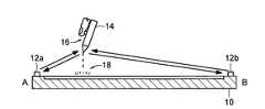
- FIG. 1is a front elevation plan view of an electronic display having an antenna grid of transducers mounted beneath the upper surface of the display or, alternatively, at least two transducers mounted upon the upper surface of the display, and in both instances the transducers and related circuitry are used to triangulate the position of a stylus tip arranged near a particular region of the display;
- FIG. 2 ais a cross-section view along plane 2 of FIG. 1 , showing a signal sent between the stylus and the transducer grid;
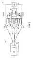
- FIG. 3is a block diagram of one form by which the transferred signal is used to triangulate the position of a stylus tip relative to the XY plane of the display;
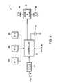
- FIG. 4is a block diagram of the stylus
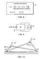
- FIG. 5is a block diagram of the dual-mode barcode scan and pointer functionality of the stylus in communication with the display for programming the button functions either manually or through the graphic user interface of the display driver circuitry;
- FIG. 6is a partial cross-sectional view of the stylus tip
- FIG. 7is a screen shot of a window displayed on the electronic display having a GUI for setting properties of the stylus
- FIG. 8is a screen shot of a window display upon activating the wireless operation properties button of FIG. 7 for setting the functionality of one or more buttons upon a stylus, and for assigning a pointer identification number to that stylus;
- FIG. 9is one example by which the assigned pointer identification number can be sent along with a packet of digital information representing the button function, or used to modulate the resonate frequency of an acoustic signal sent from the stylus to differentiate possibly multiple styluses from each other, each of which can be concurrently used as pointers upon a single display; and
- FIG. 10is a side elevation view of multiple styluses that can be used concurrently upon a single display.
- the term “contactless”generally refers to a stylus having a tip that does not contact the surface of an electronic display. Moreover, the contactless tip is operational outside the surface region of the display, and more than one or two inches from the display surface.
- the term “pointer-type stylus,” hereinafter simply “stylus,”is an electronic input device having a mechanism for pointing to a region on the electronic display and selecting that region. The region of the electronic display being pointed to is generally illustrated with a cursor at the pointed-to position.
- functionrefers to the various mechanisms by which the stylus can move, pan, scroll or select an icon, text, or graphic image displayed on a portion of the electronic display.
- any selection functioncan be programmed to a particular button or series of buttons to input a command into a computer and/or storage device by virtue of positioning the present stylus over a selectable region, and clicking the programmed button.
- Each buttoncan also be programmed to perform a macro series of programmed steps, each step can represent an individual function or a portion of an individual function to allow the depression of a single button to perform several functions in sequence.
- FIG. 1illustrates an electronic display 10 .
- a grid of transducersArranged beneath the upper surface of the display 10 viewing surface is a grid of transducers, generally referred to as an antennae grid.
- the gridcomprises a multiplicity of magnetostrictive transmitting and receiving media disposed parallel with the viewing surface and extending in an X and Y direction. Magnetostrictive vibrations are imparted periodically from one end to the other.
- stylus 14approaches the display surface, the vibrations caused by impingement of acoustic waves sent to stylus 14 from the antennae and thereafter received upon the grid determines the position of stylus 14 relative to the X and Y coordinates of the display.
- the vibrationsare detected by coils or sense amplifiers arranged at or near the terminal ends of each of the X and Y columnar and row antennae grid members. Details of an exemplary magnetostrictive antennae grid structure with receiver and transmitter functionality is set forth in U.S. Pat. No. 4,786,765, herein incorporated by reference.
- At the terminal ends of each of the X and Y columnar and row membersare receiver/transmitter, or transducers 12 .
- transducers 12At the terminal ends of each of the X and Y columnar and row members are receiver/transmitter, or transducers 12 .
- transducers 12For sake of brevity in the drawing, only a few of possibly hundreds of transducers are shown. It is understood that an increase in the number of transducers 12 in the X and Y direction will increase the stylus positional resolution.
- a transduceris a device that converts one form of energy into another.
- transducers 12convert a wireless signal, such as an electromagnetic, acoustic, optical, or magnetic signal, into an electrical signal and vice-versa.
- transducers 12can convert sound, light, heat, radio waves, or other forms of energy sent across a wireless medium into alternating or direct electric current.
- Common examples of transducersinclude buzzers, speakers, microphones, piezo-electric crystals, light-emitting and infrared-emitting diodes, photo cells, charge-coupled devices, photo detectors, and antennas, etc.
- Transducers 12can be near the outer edges of the grid.
- Stylus 14also includes a transducer and a transceiver placed near the tip of stylus 14 .
- the tipis recognized as a region of stylus 14 that converges down to a point, where the point or tip is placed nearest the upper surface of display 10 .
- the transceiveris a combination transmitter and receiver that sends and receives the electrical current generated by or sent to the transducer also within the tip.
- the tipWhen stylus 14 is activated, the tip can send and receive a signal. The signal is transferred between the tip and transducers 12 . Regardless of whether the signal is a magnetic, optical, or acoustic signal, a time delay or phase shift occurs between the tip of stylus 14 and each of the transducers 12 . The magnitude of that time delay depends on the position of the tip relative to the transducers. Measuring the magnitude of the vibration at each transducer 12 determines the predominant pair of transducers. Armed with the peak amplitude among the transducers arranged in the X and Y directions, the position of the stylus 14 can be determined relative to the display surface.
- an exposed set of transducers 12can be arranged on the surface of the display, rather than hidden beneath the display as in the case of an antenna grid.
- the exposed transducers 12can be used to send and receive an acoustic wave.
- the received acoustic wavecan be sent to detection circuit coupled to the transducers to discern a time delay between when the transducers received the acoustic wave reflected back from the stylus 14 .
- the time delayis used to triangulate the position of stylus 14 relative to the two-dimensional planar surface of display 10 . Details of acoustic wave triangulation are described in U.S. Pat. No. 4,814,552, herein incorporated by reference.
- At least one additional transduceris arranged at the surface of the display and exposed to a wireless transmission medium to receive functional information associated with various buttons upon the stylus, receive optically read information as to a scanned image sent from the stylus, and to possibly transmit program information from a graphical user interface (GUI) to the stylus in order to program the stylus buttons.
- GUIgraphical user interface
- FIG. 2illustrates a cross-sectional view along plane 2 of FIG. 1 .
- a signalis sent between stylus 14 and transducers 12 a and 12 b (as well as other transducers 12 in the X and Y-directions) to calculate a position of stylus 14 .
- a button 16can be depressed.
- the buttoncan be programmed to perform various functions. For example, the button can be programmed as a left-click similar to a left-click function on a mouse.
- the detected position of stylus 14 over a region 18 of display 10can be selected, similar to when a user moves a cursor across the displayed window via movement of a mouse and then clicking the left button on that mouse.
- stylus positioncan be determined by simply sensing which pair of transducers in the X and Y directions produce the greatest magnetostrictive energy whenever the transducers send an acoustic signal to the stylus that is resonated back to the transducers.
- the transducers in the X and Y plane nearest the styluswill undergo the greatest sensed energy, thus pinpointing where within the array (or X/Y plane) the tip is nearest.
- Another examplemight be through use of a delay reading. The transducer pair that receives the resonated-back signal the soonest might therefore triangulate the position of the stylus tip.
- a mechanism used to determine the time delay differencemight be through use of counters as shown in FIG. 3 .
- an oscillatorsuch as a crystal oscillator 20
- an oscillating signalcan be converted to a squarewave and divided down in frequency via counters 22 a and 22 b .
- Counters 22 a and 22 bcan be arranged within display 10 and coupled to transducers 12 a and 12 b , respectively. The divided-down frequency thereby bears a clock cycle of duration T. Time T can thereafter be used to set and reset counters 24 a and 24 b.
- Transceiver 26can receive the oscillating squarewave signal from transmitters 30 a and 30 b associated with transducers 12 a and 12 b , respectively.
- resonant circuit 28assumes a resonant frequency that can be varied by virtue of possible changes to the capacitor and inductor values, as will be described below.
- the received signalcan be modulated if necessary to setup a particular function.
- the capacitor within resonant circuit 28 as well as the inductorcan be set so that the received signal is modulated and sent back via transceiver 26 to receiver circuits 32 a and 32 b .
- Receiver circuits 32 a and 32 bare placed near transducers 12 a and 12 b , respectively. Accordingly, depending on the distance between stylus 14 and transducers 12 a and 12 b , the number of pulses counted by counters 24 a and 24 b will vary. In the example shown, if the distance between stylus 14 and transducer 12 b is longer than the distance between stylus 14 and transducer 12 a , there will be fewer pulses counted by counter 24 b than counter 24 a within time T. A position detection engine 34 will count the pulse number difference and, based on that difference, will quantify the position of stylus 14 relative to transducers 12 a and 12 b.
- the stylus 14can include an energy source, such as a battery or rechargeable capacitor that is used to maintain power to a memory device.
- an energy sourcesuch as a battery or rechargeable capacitor that is used to maintain power to a memory device.
- the stylus 14Upon receiving a start signal, the stylus 14 initiates a fetch procedure whereby a set of digital pulses are fetched from the memory device.
- the digital pulsesare sent as a packet of digital 1s and 0s from stylus 14 and received upon the sense amplifiers of transducers 12 a and 12 b .
- a digital pulse generatorcan be used instead of an analog resonator circuit 28 .
- the digital pulsescan be counted to determine which pair of transducers receives the packet of information the soonest. Once the first-receiving pair of transducers is determined in the X and Y arrangement, the stylus position is determined relative to the display surface.
- position detection engine 34can easily accommodate three sets of counters, or more, to triangulate a two- or possibly three-dimensional position. For sake of brevity and clarity in the drawing, however, only two sets are shown; however, it is readily apparent to the skilled artisan that two- and possible three-dimensional triangulation can occur depending on the number of counters and transducers used. It is also apparent that the signal sent between the transducers and the stylus can be modulated and thereafter demodulated unique to representing a position of the stylus, different from another signal that can be sent between the stylus and the transducers that is modulated different from the positional signal. In this fashion, the same wireless medium can be used to send not only positional signals, but also functional signals representative of a button function or a pointer identification number of one or more styluses concurrently communicating with the electronic display 10 .
- FIG. 4illustrates in block diagram several components of stylus 14 .
- a controller 36can be used to receive programmable input.
- the inputconstitutes instructions used for assigning a set of logic values to each of one or more buttons 38 a , 38 b , and 38 c arranged upon stylus 14 .
- the buttonscan be user-actuated and a corresponding set of logic values sent to controller 36 via, for example, a lookup operation.
- the fetched logic valuescan then be sent as a set of digital logic values within a packet of information to transceiver 40 and then outward to the electronic display via antenna 42 .
- the fetched logic valuescan be used to modulate a carrier signal, wherein the modulated signal is sent to a transceiver 40 and then outward to the electronic display via antenna 42 .
- One or more buttonscan also be programmed to initiate an optical signal so that possibly another transceiver, if the first transceiver sends an acoustic or magnetic signal, can send an optical signal via a light-emitting diode 44 to an image having optically contrasting printed information, such as darkened lines spaced from each other similar to a barcode.
- An energy source 46can be used to power the circuitry of stylus 14 , including maintaining power to volatile memory which contains the programmed logic values corresponding to various buttons.
- Energy source 46can be either a battery or a rechargeable voltage storage device, or capacitor.
- stylus a capacitorWhen placed into a docking system, stylus a capacitor can be recharged relatively easy, and quickly, as compared to a rechargeable battery, for example.
- a force gauge 48can be provided. Force gauge 48 can mechanically collapse onto possibly a switch to know when the tip comes in contact with the display surface.
- the stylusis designed to be capable primarily of contactless operation, an option may exist whereby it can operate both in contactless and contact operation.
- stylus 14is shown having two modes of operation.
- stylus 14includes a transceiver 26 that transfers a first signal to and from display 10 .
- Display 10is shown having a receiver and transmitter 32 a and 32 b .
- Receiver 32 acan demodulate 50 the incoming signal to differentiate that signal as possibly a transmitted function or possibly a positional signal in which triangulation is performed.
- only one transduceris illustrated; however, it is understood that two or more transducers are typically used to fix a position relative to display 10 .
- the encoded signalcan be decoded 52 .
- the encoded signalmight represent a particular function that is encoded different from another function, or possibly encoded different from a positional signal. If so, the decoder 52 determines what type of function or possibly the particular stylus that is sending the signal from other functions or positional signals. For example, a left-click function might have bit sequence 1100 as opposed to a right-click function of 1010 . As shown, the exemplary left-click function can be sent as a field of bits within a packet, along with the sequence of bits that uniquely represent that stylus (i.e., the PTR_ID). That information can be sent to the display driver 54 to allow the function to select the region over which the stylus is positioned.
- the PTR_IDthe sequence of bits that uniquely represent that stylus
- That informationthen gets fetched from the corresponding memory of the display microcontroller, where it is then decoded by an execution engine and the corresponding operation occurs.
- the stylus 14operates digitally instead of in an analog mode
- the information from memory 68 and 70can be sent directly to transceiver 26 , absent any need for modulation.
- the optical image or the functioncan be represented as a series of binary 1s and 0s that gets sent within a packet to the display 10 via transceiver 26 —with no need to modulate at the transmit side or demodulate at the receive side.
- Display driver 54can also produce the appropriate graphical user interface 56 to open, for example, various properties that can be selected by the user cursor.
- the operating systemcan be obtained from Microsoft Corporation as Microsoft Windows XP Tablet PC Edition®.
- the operating system 58thereby implements the appropriate graphical user interface that can be selected by a user and output onto the display drivers 54 or possibly onto the transmitter 32 b if the GUI to program various button functions, as will be described below.
- Stylus 14implements transceiver 26 to fix the positional orientation of the stylus tip as well as to send encoded logic values representative of programmed button functions.
- another transceiver 60can be used to send and receive optical signals onto a graphical image, possibly a barcode of alternating thick and thin stripes with different spacings on a white background.
- the graphical image 62receives an optical signal from light-emitting diode 64 , and emits an optical reflected signal onto photo detector 66 .
- Photo detector 66can include an array of photodetectors with a charge-coupled device (CCD).
- the charge packets in each photodetector of the arraycan be simultaneously transferred by charge coupling to a parallel CCD shift register to determine the light and dark outlines of the optically contrasting two-dimension (or one-dimensional) image 62 .
- image 62is a barcode indicia
- indiciapreferably includes encoded universal product code (UPC) information pertinent to the product to which the barcode label is affixed.
- Photo detector 66receives a signal of logic 1 and logic 0 voltage values corresponding to ASCII code sent to, for example, a memory device 68 .
- Memory device 68can thereby perform direct memory access (DMA) in a lookup environment to convert the ASCII code to, for example, a code recognizable as UPC values.
- DMAdirect memory access
- Controller 36can receive GUI input to program certain button functions selected via GUI 56 and received by transceiver 26 onto controller 36 . Controller 36 thereafter encodes those functions into the appropriate word lines of memory 70 .
- driverscan be connected to each of the corresponding buttons and an encoding device can be placed at the interim between those drivers and memory 70 to input the programmed values by depressing a sequence of buttons or a dedicated program button with selectable scroll options using, for example, non-volatile memory or ROM.
- the non-volatile memory or ROM outputcan then be forwarded directly to the drivers and into memory 70 . Thereafter, if one or more of the buttons are depressed, the stored logic values within memory 70 are read from memory 70 and placed upon multiplexer 72 .
- multiplexer 72will either forward the image 62 code or the function code of logic 1 and logic 0 voltage values onto a carrier signal.
- the function-encoded or image-encoded signalis selectively multiplexed and sent directly as part of a digital packet, or is selectively multiplexed and modulated onto a carrier signal using various well-known modulation techniques. For example, if analog transmission is desired, the encoded signal can amplitude modulate, frequency modulate, or phase modulate the carrier signal via modulator 74 to transmit a signal across the wireless medium to receiver 32 depending on whether the input is a function (from among numerous programmable functions) or a UPC value. Demodulator 50 can then discern what type of function or image value was sent.
- FIG. 6illustrates a portion of stylus 14 having a first transceiver/transducer 26 and a second transceiver/transducer 60 .
- the first transceiveris used to send and receive a signal across a wireless medium to denote an image, function, or positional value.
- the image and functional valuesare those stored in memory and output upon the wireless medium depending on which button is depressed to actuate the function or the photo detector output.
- Transceiver 26can be implemented as a coil antenna to receive, for example, acoustic signals sent from transducers 12 ( FIG. 1 ) and to send resonating acoustic signals back to the transducers for determining the X and Y coordinates, as well as sending functional or image values.
- tip 76 of stylus 14integrated within the tip 76 of stylus 14 is an LED 64 and one or more photodetectors 66 of transceiver 60 .
- the distal end of tip 76should be optically translucent to allow the sending and receiving of optical signals.
- the received signalscan then be forwarded to memory lookup and output as an encoded signal from the transmitter of transceiver 26 .
- tip 76is designed to also contact the display surface (if desired), tip 76 can reciprocate along axis 78 to activate a switch indicating contact has been made.
- stylus 14is designed to operate in a contactless application, it is envisioned that a dual contact and contactless functionality is possible.
- controller 36can receive instructions via a GUI 56 to program memory 70 .
- the GUI functionalityoccurs in conjunction with the display driver 54 to produce possibly a user-selected set of properties shown in FIG. 7 .
- a window popup 80can occur by the user moving the stylus tip and presenting a cursor at a particular location upon the display, and then actuating a button to select that window.
- Window 80might have certain GUI properties, one of which is the wireless operation of the stylus.
- Window 82allows the user to place the cursor in any one of the boxes to the right of button 1 (BT 1 ).
- the usercan actuate a button to reconfigure the first button, among a plurality of buttons on the stylus, to the functionality selected.
- the usercan also place the cursor into the pointer identification box, and scroll up and down to change the numbers within that box by, for example, continuously depressing another button on the stylus. This will change the pointer identification number assigned to that stylus depending on the length of time (and corresponding number) at which the button is depressed and the number displayed.
- Assigning a unique pointer identification number to a stylusallows possibly more than two styluses to be operated concurrent with one another.
- the unique pointer identification numbercorresponds to a unique set of logic values stored within memory of the stylus. Those logic values can then be fetched from the memory and input into a capacitor array to form a variable capacitance value of the variable capacitor within the resonant circuit 28 shown in FIG. 9 .
- the signal sent to and from transceiver 26can be modified in frequency.
- the modified frequency signalcan be discerned from other signals that are modified to a different frequency based on their pointer identification values. This allows the PC position detection engine 34 ( FIG. 3 ) to detect a unique position for each stylus since each stylus now changes the resonant frequency by a unique pointer identification value amount.
- FIG. 10illustrates possibly one way in which the resonant circuit modifies the resonant frequency so that even though the transducers 12 a and 12 b emit the same frequency to two or more styluses 14 a and 14 b , the return signal from stylus 14 a resonates at a different frequency than that from stylus 14 b , as detected by transducers 12 a and 12 b .
- the return signalcan be time division multiplexed and counters assigned to fix the positional value of each of possibly a plurality of styluses to allow multiple pointer-type styluses to be operating concurrent with one another.
- Each styluscan have its own unique pointer identification value, and that value can be stored for example in non-volatile memory of the stylus.
- the pointer identification valuecan be fetched on a configuration or start up routine, and loaded into memory 70 ( FIG. 5 ). Thereafter, whenever a packet of function and/or image information is sent from a stylus 14 to display 10 , the packet can also contain the pointer identification value unique to that stylus.
Landscapes
- Engineering & Computer Science (AREA)
- General Engineering & Computer Science (AREA)
- Theoretical Computer Science (AREA)
- Physics & Mathematics (AREA)
- Human Computer Interaction (AREA)
- General Physics & Mathematics (AREA)
- Acoustics & Sound (AREA)
- Electromagnetism (AREA)
- Position Input By Displaying (AREA)
Abstract
Description
Claims (17)
Priority Applications (2)
| Application Number | Priority Date | Filing Date | Title |
|---|---|---|---|
| US11/032,369US7646379B1 (en) | 2005-01-10 | 2005-01-10 | Wireless and contactless electronic input stylus having at least one button with optical scan and programmable pointer functionality |
| US12/642,999US8345023B1 (en) | 2005-01-10 | 2009-12-21 | Wireless and contactless electronic input stylus having at least one button with optical scan and programmable pointer functionality |
Applications Claiming Priority (1)
| Application Number | Priority Date | Filing Date | Title |
|---|---|---|---|
| US11/032,369US7646379B1 (en) | 2005-01-10 | 2005-01-10 | Wireless and contactless electronic input stylus having at least one button with optical scan and programmable pointer functionality |
Related Child Applications (1)
| Application Number | Title | Priority Date | Filing Date |
|---|---|---|---|
| US12/642,999DivisionUS8345023B1 (en) | 2005-01-10 | 2009-12-21 | Wireless and contactless electronic input stylus having at least one button with optical scan and programmable pointer functionality |
Publications (1)
| Publication Number | Publication Date |
|---|---|
| US7646379B1true US7646379B1 (en) | 2010-01-12 |
Family
ID=41479502
Family Applications (2)
| Application Number | Title | Priority Date | Filing Date |
|---|---|---|---|
| US11/032,369Active2026-10-23US7646379B1 (en) | 2005-01-10 | 2005-01-10 | Wireless and contactless electronic input stylus having at least one button with optical scan and programmable pointer functionality |
| US12/642,999Active2026-06-28US8345023B1 (en) | 2005-01-10 | 2009-12-21 | Wireless and contactless electronic input stylus having at least one button with optical scan and programmable pointer functionality |
Family Applications After (1)
| Application Number | Title | Priority Date | Filing Date |
|---|---|---|---|
| US12/642,999Active2026-06-28US8345023B1 (en) | 2005-01-10 | 2009-12-21 | Wireless and contactless electronic input stylus having at least one button with optical scan and programmable pointer functionality |
Country Status (1)
| Country | Link |
|---|---|
| US (2) | US7646379B1 (en) |
Cited By (57)
| Publication number | Priority date | Publication date | Assignee | Title |
|---|---|---|---|---|
| US20070002022A1 (en)* | 2005-07-04 | 2007-01-04 | Chul-Yong Joung | Optical pointing device, optical pointing system, and method of operating the same |
| US20080122792A1 (en)* | 2006-11-27 | 2008-05-29 | Microsoft Corporation | Communication with a Touch Screen |
| US20080169132A1 (en)* | 2007-01-03 | 2008-07-17 | Yao Ding | Multiple styli annotation system |
| US20080238885A1 (en)* | 2007-03-29 | 2008-10-02 | N-Trig Ltd. | System and method for multiple object detection on a digitizer system |
| US20090122008A1 (en)* | 2007-11-14 | 2009-05-14 | Boulder Innovation Group, Inc. | Probe With A Virtual Marker |
| US20090173533A1 (en)* | 2008-01-07 | 2009-07-09 | Apple Inc. | Flexible data cable |
| US20090296162A1 (en)* | 2007-11-26 | 2009-12-03 | Optelec Development B.V. | Reproduction device, assembly of a reproductive device and an indication body, and a method for reproducing an image portion |
| US20100073290A1 (en)* | 2007-03-07 | 2010-03-25 | Ralf Moenkemoeller | Operating device with a transmitter and a receiver |
| US20110090146A1 (en)* | 2009-10-19 | 2011-04-21 | Wacom Co., Ltd. | Position detector and position indicator |
| US20110148798A1 (en)* | 2008-06-04 | 2011-06-23 | Elliptic Laboratories As | Object location |
| US20110157094A1 (en)* | 2006-11-27 | 2011-06-30 | Microsoft Corporation | Infrared sensor integrated in a touch panel |
| US20110164000A1 (en)* | 2010-01-06 | 2011-07-07 | Apple Inc. | Communicating stylus |
| US20110162894A1 (en)* | 2010-01-06 | 2011-07-07 | Apple Inc. | Stylus for touch sensing devices |
| GB2479458A (en)* | 2010-04-08 | 2011-10-12 | Avaya Inc | Correlating the mode or identification of an input prosthetic with a function |
| US8094129B2 (en) | 2006-11-27 | 2012-01-10 | Microsoft Corporation | Touch sensing using shadow and reflective modes |
| US8110744B2 (en) | 2008-08-19 | 2012-02-07 | Apple Inc. | Flexible shielded cable |
| US20120194483A1 (en)* | 2011-01-27 | 2012-08-02 | Research In Motion Limited | Portable electronic device and method therefor |
| US8345023B1 (en)* | 2005-01-10 | 2013-01-01 | Motion Computing, Inc. | Wireless and contactless electronic input stylus having at least one button with optical scan and programmable pointer functionality |
| WO2013153551A1 (en)* | 2012-04-08 | 2013-10-17 | N-Trig Ltd. | Stylus and digitizer for 3d manipulation of virtual objects |
| US20130286033A1 (en)* | 2012-04-26 | 2013-10-31 | Research In Motion Limited | Method and apparatus for drawing tool selection |
| US20140035843A1 (en)* | 2012-08-02 | 2014-02-06 | Sungho Zo | Electronic device and electronic note system using the same |
| US20140084907A1 (en)* | 2012-09-27 | 2014-03-27 | Wacom Co., Ltd. | Electromagnetic induction position detection sensor |
| US8687172B2 (en) | 2011-04-13 | 2014-04-01 | Ivan Faul | Optical digitizer with improved distance measurement capability |
| EP2738651A2 (en)* | 2012-11-30 | 2014-06-04 | Samsung Electronics Co., Ltd | Electronic device for providing hovering input effects and method for controlling the same |
| WO2014128712A1 (en)* | 2013-02-25 | 2014-08-28 | N-Trig Ltd. | Stylus for a digitizer system |
| US20140253465A1 (en)* | 2013-03-11 | 2014-09-11 | Barnesandnoble.Com Llc | Stylus sensitive device with hover over stylus control functionality |
| TWI459246B (en)* | 2011-09-09 | 2014-11-01 | ||
| US8957878B2 (en) | 2012-07-31 | 2015-02-17 | Blackberry Limited | Apparatus and method for selecting stylus location-determination information provided by a plurality of non-passive stylus-location modalities |
| US20150248189A1 (en)* | 2012-09-26 | 2015-09-03 | Light Blue Optics Ltd. | Touch Sensing Systems |
| KR20150125491A (en)* | 2014-04-30 | 2015-11-09 | 삼성전자주식회사 | Method for detecting touch-input, apparatus for sensing touch-input, and apparatus for inputting touch-input |
| US9182840B2 (en) | 2012-07-31 | 2015-11-10 | Blackberry Limited | Apparatus and method pertaining to a stylus having a plurality of non-passive location modalities |
| US20160070391A1 (en)* | 2014-09-05 | 2016-03-10 | Fu Tai Hua Industry (Shenzhen) Co., Ltd. | Electronic device and method for controlling displayed interface according to posture of input device |
| US20160124528A1 (en)* | 2014-11-03 | 2016-05-05 | Lenovo (Singapore) Pte. Ltd. | Stylus button function |
| US9639179B2 (en) | 2012-09-14 | 2017-05-02 | Apple Inc. | Force-sensitive input device |
| US9639178B2 (en) | 2010-11-19 | 2017-05-02 | Apple Inc. | Optical stylus |
| US9690394B2 (en) | 2012-09-14 | 2017-06-27 | Apple Inc. | Input device having extendable nib |
| US9746944B2 (en) | 2015-01-04 | 2017-08-29 | Microsoft Technology Licensing, Llc | Universal stylus communication with a digitizer |
| US9785259B2 (en) | 2013-03-11 | 2017-10-10 | Barnes & Noble College Booksellers, Llc | Stylus-based slider functionality for UI control of computing device |
| EP2565770A3 (en)* | 2011-08-31 | 2017-10-25 | Samsung Electronics Co., Ltd. | A portable apparatus and an input method of a portable apparatus |
| US20180101250A1 (en)* | 2015-06-29 | 2018-04-12 | Wacom Co., Ltd. | Position detection device and position indicator |
| US9946365B2 (en)* | 2013-03-11 | 2018-04-17 | Barnes & Noble College Booksellers, Llc | Stylus-based pressure-sensitive area for UI control of computing device |
| US10613666B2 (en) | 2016-07-15 | 2020-04-07 | Apple Inc. | Content creation using electronic input device on non-electronic surfaces |
| CN111527470A (en)* | 2017-12-14 | 2020-08-11 | 法国比克公司 | Active stylus |
| US10955941B2 (en) | 2019-03-26 | 2021-03-23 | Atlantic Health System, Inc. | Multimodal input device and system for wireless record keeping in a multi-user environment |
| CN113268174A (en)* | 2021-03-15 | 2021-08-17 | 荣耀终端有限公司 | Function control method and system |
| US11132074B2 (en)* | 2015-05-21 | 2021-09-28 | Wacom Co., Ltd. | Active stylus |
| US11188144B2 (en) | 2018-01-05 | 2021-11-30 | Samsung Electronics Co., Ltd. | Method and apparatus to navigate a virtual content displayed by a virtual reality (VR) device |
| US11347367B2 (en) | 2019-01-18 | 2022-05-31 | Dell Products L.P. | Information handling system see do user interface management |
| US20220365613A1 (en)* | 2011-07-27 | 2022-11-17 | Wacom Co., Ltd. | Active stylus and capacitive position detection system |
| US11614806B1 (en) | 2021-05-12 | 2023-03-28 | Apple Inc. | Input device with self-mixing interferometry sensors |
| US11656654B2 (en) | 2019-01-18 | 2023-05-23 | Dell Products L.P. | Portable information handling system user interface selection based on keyboard configuration |
| US11946996B2 (en) | 2020-06-30 | 2024-04-02 | Apple, Inc. | Ultra-accurate object tracking using radar in multi-object environment |
| US12086362B2 (en) | 2017-09-01 | 2024-09-10 | Flatfrog Laboratories Ab | Optical component |
| US12175044B2 (en) | 2017-02-06 | 2024-12-24 | Flatfrog Laboratories Ab | Optical coupling in touch-sensing systems |
| US12282653B2 (en) | 2020-02-08 | 2025-04-22 | Flatfrog Laboratories Ab | Touch apparatus with low latency interactions |
| US12353649B2 (en) | 2022-06-29 | 2025-07-08 | Apple Inc. | Input device with optical sensors |
| US12443293B2 (en) | 2024-04-23 | 2025-10-14 | Wacom Co., Ltd. | Stylus detection system having touch object detecting mode and stylus detecting mode |
Families Citing this family (5)
| Publication number | Priority date | Publication date | Assignee | Title |
|---|---|---|---|---|
| EP3470963B1 (en) | 2009-07-07 | 2021-03-10 | Elliptic Laboratories AS | Control using movements |
| US9507442B2 (en) | 2014-05-21 | 2016-11-29 | Leap Motion, Inc. | Multi-function stylus for motion capture and sensory based machine control |
| US20170242498A1 (en)* | 2016-02-23 | 2017-08-24 | Motorola Mobility Llc | Passive Chopsticks Stylus System for Capacitive Touch Screens |
| US11815968B2 (en)* | 2017-12-14 | 2023-11-14 | Societe Bic | Stylus for a touchscreen |
| US12189902B2 (en) | 2023-01-18 | 2025-01-07 | Apple Inc. | Photo-sensing enabled display for touch detection with customized photodiode and light emitting diode component level angular response |
Citations (18)
| Publication number | Priority date | Publication date | Assignee | Title |
|---|---|---|---|---|
| US4786765A (en) | 1986-07-23 | 1988-11-22 | Wacom Co., Ltd. | Coordinates input system |
| US4814552A (en) | 1987-12-02 | 1989-03-21 | Xerox Corporation | Ultrasound position input device |
| US5004871A (en) | 1989-11-13 | 1991-04-02 | Summagraphics Corporation | Digitizer stylus having side switch |
| US5109141A (en) | 1989-11-13 | 1992-04-28 | Summagraphics Corporation | Digitizer stylus with z-axis side control |
| US5138304A (en)* | 1990-08-02 | 1992-08-11 | Hewlett-Packard Company | Projected image light pen |
| US5227622A (en) | 1992-02-06 | 1993-07-13 | Digital Stream Corp. | Wireless input system for computer using pen position detection |
| US5565632A (en) | 1995-02-20 | 1996-10-15 | Wacom Co., Ltd. | Pressure sensitive stylus pen |
| US5576502A (en) | 1995-06-06 | 1996-11-19 | Wacom Co., Ltd. | Pointing unit and improved stylus pen |
| US5717435A (en) | 1995-06-16 | 1998-02-10 | Wacom Co., Ltd. | Side switch mechanism, and stylus pen using the same |
| US5729251A (en)* | 1995-02-09 | 1998-03-17 | Fuji Xerox Co., Ltd. | Information input/output system |
| US5914783A (en)* | 1997-03-24 | 1999-06-22 | Mistubishi Electric Information Technology Center America, Inc. | Method and apparatus for detecting the location of a light source |
| US6111565A (en)* | 1998-05-14 | 2000-08-29 | Virtual Ink Corp. | Stylus for use with transcription system |
| US6195446B1 (en) | 1994-12-16 | 2001-02-27 | Hyundai Electronics America | Digitizer stylus with memory for storing handwriting data |
| US6335727B1 (en)* | 1993-03-12 | 2002-01-01 | Kabushiki Kaisha Toshiba | Information input device, position information holding device, and position recognizing system including them |
| US20020190963A1 (en)* | 2001-06-14 | 2002-12-19 | Koninklijke Philips Electronics N.V. | Data input system |
| US6577299B1 (en) | 1998-08-18 | 2003-06-10 | Digital Ink, Inc. | Electronic portable pen apparatus and method |
| US6714310B1 (en)* | 1999-09-06 | 2004-03-30 | Canon Kabushiki Kaisha | Coordinate input apparatus and method, and computer-readable memory therefor |
| US20060022942A1 (en)* | 2004-07-30 | 2006-02-02 | Po-Chi Lin | Control method for operating a computer cursor instinctively and the apparatus thereof |
Family Cites Families (1)
| Publication number | Priority date | Publication date | Assignee | Title |
|---|---|---|---|---|
| US7646379B1 (en)* | 2005-01-10 | 2010-01-12 | Motion Computing, Inc. | Wireless and contactless electronic input stylus having at least one button with optical scan and programmable pointer functionality |
- 2005
- 2005-01-10USUS11/032,369patent/US7646379B1/enactiveActive
- 2009
- 2009-12-21USUS12/642,999patent/US8345023B1/enactiveActive
Patent Citations (18)
| Publication number | Priority date | Publication date | Assignee | Title |
|---|---|---|---|---|
| US4786765A (en) | 1986-07-23 | 1988-11-22 | Wacom Co., Ltd. | Coordinates input system |
| US4814552A (en) | 1987-12-02 | 1989-03-21 | Xerox Corporation | Ultrasound position input device |
| US5004871A (en) | 1989-11-13 | 1991-04-02 | Summagraphics Corporation | Digitizer stylus having side switch |
| US5109141A (en) | 1989-11-13 | 1992-04-28 | Summagraphics Corporation | Digitizer stylus with z-axis side control |
| US5138304A (en)* | 1990-08-02 | 1992-08-11 | Hewlett-Packard Company | Projected image light pen |
| US5227622A (en) | 1992-02-06 | 1993-07-13 | Digital Stream Corp. | Wireless input system for computer using pen position detection |
| US6335727B1 (en)* | 1993-03-12 | 2002-01-01 | Kabushiki Kaisha Toshiba | Information input device, position information holding device, and position recognizing system including them |
| US6195446B1 (en) | 1994-12-16 | 2001-02-27 | Hyundai Electronics America | Digitizer stylus with memory for storing handwriting data |
| US5729251A (en)* | 1995-02-09 | 1998-03-17 | Fuji Xerox Co., Ltd. | Information input/output system |
| US5565632A (en) | 1995-02-20 | 1996-10-15 | Wacom Co., Ltd. | Pressure sensitive stylus pen |
| US5576502A (en) | 1995-06-06 | 1996-11-19 | Wacom Co., Ltd. | Pointing unit and improved stylus pen |
| US5717435A (en) | 1995-06-16 | 1998-02-10 | Wacom Co., Ltd. | Side switch mechanism, and stylus pen using the same |
| US5914783A (en)* | 1997-03-24 | 1999-06-22 | Mistubishi Electric Information Technology Center America, Inc. | Method and apparatus for detecting the location of a light source |
| US6111565A (en)* | 1998-05-14 | 2000-08-29 | Virtual Ink Corp. | Stylus for use with transcription system |
| US6577299B1 (en) | 1998-08-18 | 2003-06-10 | Digital Ink, Inc. | Electronic portable pen apparatus and method |
| US6714310B1 (en)* | 1999-09-06 | 2004-03-30 | Canon Kabushiki Kaisha | Coordinate input apparatus and method, and computer-readable memory therefor |
| US20020190963A1 (en)* | 2001-06-14 | 2002-12-19 | Koninklijke Philips Electronics N.V. | Data input system |
| US20060022942A1 (en)* | 2004-07-30 | 2006-02-02 | Po-Chi Lin | Control method for operating a computer cursor instinctively and the apparatus thereof |
Non-Patent Citations (2)
| Title |
|---|
| "programming." Merriam-Webster Online Dictionary. 2009. Merriam-Webster Online. Apr. 14, 2009; .* |
| "programming." Merriam-Webster Online Dictionary. 2009. Merriam-Webster Online. Apr. 14, 2009; <http://www.merriam-webster.com/dictionary/programming>.* |
Cited By (105)
| Publication number | Priority date | Publication date | Assignee | Title |
|---|---|---|---|---|
| US8345023B1 (en)* | 2005-01-10 | 2013-01-01 | Motion Computing, Inc. | Wireless and contactless electronic input stylus having at least one button with optical scan and programmable pointer functionality |
| US8013287B2 (en)* | 2005-07-04 | 2011-09-06 | Atlab Inc. | Optical pointing device, optical pointing system, and method of operating the same |
| US20070002022A1 (en)* | 2005-07-04 | 2007-01-04 | Chul-Yong Joung | Optical pointing device, optical pointing system, and method of operating the same |
| US20110157094A1 (en)* | 2006-11-27 | 2011-06-30 | Microsoft Corporation | Infrared sensor integrated in a touch panel |
| US20080122792A1 (en)* | 2006-11-27 | 2008-05-29 | Microsoft Corporation | Communication with a Touch Screen |
| US8411070B2 (en) | 2006-11-27 | 2013-04-02 | Microsoft Corporation | Infrared sensor integrated in a touch panel |
| US8368663B2 (en) | 2006-11-27 | 2013-02-05 | Microsoft Corporation | Touch sensing using shadow and reflective modes |
| US8466902B2 (en) | 2006-11-27 | 2013-06-18 | Microsoft Corporation | Infrared sensor integrated in a touch panel |
| US8269746B2 (en)* | 2006-11-27 | 2012-09-18 | Microsoft Corporation | Communication with a touch screen |
| US8094129B2 (en) | 2006-11-27 | 2012-01-10 | Microsoft Corporation | Touch sensing using shadow and reflective modes |
| US8780088B2 (en) | 2006-11-27 | 2014-07-15 | Microsoft Corporation | Infrared sensor integrated in a touch panel |
| US20110169779A1 (en)* | 2006-11-27 | 2011-07-14 | Microsoft Corporation | Infrared sensor integrated in a touch panel |
| JP2010515195A (en)* | 2007-01-03 | 2010-05-06 | ルイディア インコーポレイテッド | Multiple stylus annotation system |
| US20080169132A1 (en)* | 2007-01-03 | 2008-07-17 | Yao Ding | Multiple styli annotation system |
| US20100073290A1 (en)* | 2007-03-07 | 2010-03-25 | Ralf Moenkemoeller | Operating device with a transmitter and a receiver |
| US8305347B2 (en)* | 2007-03-07 | 2012-11-06 | Paragon Ag | Operating device with a transmitter and a receiver |
| US20080238885A1 (en)* | 2007-03-29 | 2008-10-02 | N-Trig Ltd. | System and method for multiple object detection on a digitizer system |
| US9746981B2 (en)* | 2007-03-29 | 2017-08-29 | Microsoft Technology Licensing, Llc | System and method for multiple object detection on a digitizer system |
| US10503340B2 (en) | 2007-03-29 | 2019-12-10 | Microsoft Technology Licensing, Llc | System and method for multiple object detection on a digitizer system |
| US8638451B2 (en) | 2007-11-14 | 2014-01-28 | Ivan Faul | System for determining a location on a 2D surface or in a 3D volume |
| US8294082B2 (en)* | 2007-11-14 | 2012-10-23 | Boulder Innovation Group, Inc. | Probe with a virtual marker |
| US20090122008A1 (en)* | 2007-11-14 | 2009-05-14 | Boulder Innovation Group, Inc. | Probe With A Virtual Marker |
| US20090296162A1 (en)* | 2007-11-26 | 2009-12-03 | Optelec Development B.V. | Reproduction device, assembly of a reproductive device and an indication body, and a method for reproducing an image portion |
| US8610965B2 (en)* | 2007-11-26 | 2013-12-17 | Optelec Development B.V. | Reproduction device, assembly of a reproductive device and an indication body, and a method for reproducing an image portion |
| US8587953B2 (en) | 2008-01-07 | 2013-11-19 | Apple Inc. | Flexible data cable |
| US8067701B2 (en)* | 2008-01-07 | 2011-11-29 | Apple Inc. | I/O connectors with extendable faraday cage |
| US20090173534A1 (en)* | 2008-01-07 | 2009-07-09 | Apple Inc. | I/o connectors with extendable faraday cage |
| US20090173533A1 (en)* | 2008-01-07 | 2009-07-09 | Apple Inc. | Flexible data cable |
| US20110148798A1 (en)* | 2008-06-04 | 2011-06-23 | Elliptic Laboratories As | Object location |
| US8110744B2 (en) | 2008-08-19 | 2012-02-07 | Apple Inc. | Flexible shielded cable |
| US10185412B2 (en) | 2009-10-19 | 2019-01-22 | Wacom Co., Ltd. | Positioning indicator and position indication method |
| US8982044B2 (en)* | 2009-10-19 | 2015-03-17 | Wacom Co., Ltd. | Position detector and position indicator |
| US9600117B2 (en)* | 2009-10-19 | 2017-03-21 | Wacom Co., Ltd. | Position detector and position indicator |
| US10185411B2 (en) | 2009-10-19 | 2019-01-22 | Wacom Co., Ltd. | Position detector and position indicator |
| US9459726B2 (en) | 2009-10-19 | 2016-10-04 | Wacom Co., Ltd. | Position detector and position indicator |
| US20160179280A1 (en)* | 2009-10-19 | 2016-06-23 | Wacom Co., Ltd. | Position detector and position indicator |
| US20110090146A1 (en)* | 2009-10-19 | 2011-04-21 | Wacom Co., Ltd. | Position detector and position indicator |
| US20110164000A1 (en)* | 2010-01-06 | 2011-07-07 | Apple Inc. | Communicating stylus |
| US8922530B2 (en) | 2010-01-06 | 2014-12-30 | Apple Inc. | Communicating stylus |
| US20110162894A1 (en)* | 2010-01-06 | 2011-07-07 | Apple Inc. | Stylus for touch sensing devices |
| GB2479458A (en)* | 2010-04-08 | 2011-10-12 | Avaya Inc | Correlating the mode or identification of an input prosthetic with a function |
| US9639178B2 (en) | 2010-11-19 | 2017-05-02 | Apple Inc. | Optical stylus |
| US20120194483A1 (en)* | 2011-01-27 | 2012-08-02 | Research In Motion Limited | Portable electronic device and method therefor |
| US9417696B2 (en)* | 2011-01-27 | 2016-08-16 | Blackberry Limited | Portable electronic device and method therefor |
| US8687172B2 (en) | 2011-04-13 | 2014-04-01 | Ivan Faul | Optical digitizer with improved distance measurement capability |
| US20220365613A1 (en)* | 2011-07-27 | 2022-11-17 | Wacom Co., Ltd. | Active stylus and capacitive position detection system |
| US11995250B2 (en)* | 2011-07-27 | 2024-05-28 | Wacom Co., Ltd. | Active stylus and capacitive position detection system having touch object detecting mode and stylus detecting mode |
| EP2565770A3 (en)* | 2011-08-31 | 2017-10-25 | Samsung Electronics Co., Ltd. | A portable apparatus and an input method of a portable apparatus |
| TWI459246B (en)* | 2011-09-09 | 2014-11-01 | ||
| WO2013153551A1 (en)* | 2012-04-08 | 2013-10-17 | N-Trig Ltd. | Stylus and digitizer for 3d manipulation of virtual objects |
| US8963891B2 (en)* | 2012-04-26 | 2015-02-24 | Blackberry Limited | Method and apparatus for drawing tool selection |
| US20130286033A1 (en)* | 2012-04-26 | 2013-10-31 | Research In Motion Limited | Method and apparatus for drawing tool selection |
| US9182840B2 (en) | 2012-07-31 | 2015-11-10 | Blackberry Limited | Apparatus and method pertaining to a stylus having a plurality of non-passive location modalities |
| US8957878B2 (en) | 2012-07-31 | 2015-02-17 | Blackberry Limited | Apparatus and method for selecting stylus location-determination information provided by a plurality of non-passive stylus-location modalities |
| US9239646B2 (en)* | 2012-08-02 | 2016-01-19 | Lg Electronics Inc. | Electronic device and electronic note system using the same |
| US20140035843A1 (en)* | 2012-08-02 | 2014-02-06 | Sungho Zo | Electronic device and electronic note system using the same |
| US9639179B2 (en) | 2012-09-14 | 2017-05-02 | Apple Inc. | Force-sensitive input device |
| US9690394B2 (en) | 2012-09-14 | 2017-06-27 | Apple Inc. | Input device having extendable nib |
| US20150248189A1 (en)* | 2012-09-26 | 2015-09-03 | Light Blue Optics Ltd. | Touch Sensing Systems |
| US9410824B2 (en)* | 2012-09-27 | 2016-08-09 | Wacom Co., Ltd. | Electromagnetic induction position detection sensor |
| US20140084907A1 (en)* | 2012-09-27 | 2014-03-27 | Wacom Co., Ltd. | Electromagnetic induction position detection sensor |
| EP2738651A2 (en)* | 2012-11-30 | 2014-06-04 | Samsung Electronics Co., Ltd | Electronic device for providing hovering input effects and method for controlling the same |
| WO2014128712A1 (en)* | 2013-02-25 | 2014-08-28 | N-Trig Ltd. | Stylus for a digitizer system |
| CN104995586B (en)* | 2013-02-25 | 2018-11-09 | 微软科技许可有限公司 | The pen of digitization system |
| US9874949B2 (en) | 2013-02-25 | 2018-01-23 | Microsoft Technology Licensing, Llc | Stylus for a digitizer system |
| CN104995586A (en)* | 2013-02-25 | 2015-10-21 | 微软科技许可有限公司 | Stylus for a digitizer system |
| US9785259B2 (en) | 2013-03-11 | 2017-10-10 | Barnes & Noble College Booksellers, Llc | Stylus-based slider functionality for UI control of computing device |
| US9766723B2 (en)* | 2013-03-11 | 2017-09-19 | Barnes & Noble College Booksellers, Llc | Stylus sensitive device with hover over stylus control functionality |
| US9946365B2 (en)* | 2013-03-11 | 2018-04-17 | Barnes & Noble College Booksellers, Llc | Stylus-based pressure-sensitive area for UI control of computing device |
| US20140253465A1 (en)* | 2013-03-11 | 2014-09-11 | Barnesandnoble.Com Llc | Stylus sensitive device with hover over stylus control functionality |
| CN106462312B (en)* | 2014-04-30 | 2019-11-01 | 三星电子株式会社 | Detect method, the equipment for sensing touch input and the equipment for inputting touch input of touch input |
| EP3137980A4 (en)* | 2014-04-30 | 2017-12-06 | Samsung Electronics Co., Ltd. | Method of detecting touch input, apparatus for sensing touch input, and apparatus for inputting touch input |
| US9864475B2 (en) | 2014-04-30 | 2018-01-09 | Samsung Electronics Co., Ltd. | Method of detecting touch input, apparatus for sensing touch input, and apparatus for inputting touch input |
| KR20150125491A (en)* | 2014-04-30 | 2015-11-09 | 삼성전자주식회사 | Method for detecting touch-input, apparatus for sensing touch-input, and apparatus for inputting touch-input |
| US10719183B2 (en) | 2014-04-30 | 2020-07-21 | Samsung Electronics Co., Ltd. | Method of detecting touch input, apparatus for sensing touch input, and apparatus for inputting touch input |
| CN106462312A (en)* | 2014-04-30 | 2017-02-22 | 三星电子株式会社 | Method of detecting touch input, apparatus for sensing touch input, and apparatus for inputting touch input |
| US20160070391A1 (en)* | 2014-09-05 | 2016-03-10 | Fu Tai Hua Industry (Shenzhen) Co., Ltd. | Electronic device and method for controlling displayed interface according to posture of input device |
| US9766724B2 (en)* | 2014-11-03 | 2017-09-19 | Lenovo (Singapore) Pte. Ltd. | Orientation dependent stylus button function |
| US20160124528A1 (en)* | 2014-11-03 | 2016-05-05 | Lenovo (Singapore) Pte. Ltd. | Stylus button function |
| US9746944B2 (en) | 2015-01-04 | 2017-08-29 | Microsoft Technology Licensing, Llc | Universal stylus communication with a digitizer |
| US9965057B2 (en) | 2015-01-04 | 2018-05-08 | Microsoft Technology Licensing, Llc | Universal stylus communication with a digitizer |
| US9772697B2 (en) | 2015-01-04 | 2017-09-26 | Microsoft Technology Licensing, Llc | Touch down detection with a stylus |
| US12124642B2 (en) | 2015-05-21 | 2024-10-22 | Wacom Co., Ltd. | Active stylus |
| US11132074B2 (en)* | 2015-05-21 | 2021-09-28 | Wacom Co., Ltd. | Active stylus |
| US11714511B2 (en) | 2015-06-29 | 2023-08-01 | Wacom Co., Ltd. | Sensor controller and stylus |
| US10809817B2 (en)* | 2015-06-29 | 2020-10-20 | Wacom Co., Ltd. | Position detection device and position indicator |
| US12067198B2 (en) | 2015-06-29 | 2024-08-20 | Wacom Co., Ltd. | Sensor controller and stylus |
| US20180101250A1 (en)* | 2015-06-29 | 2018-04-12 | Wacom Co., Ltd. | Position detection device and position indicator |
| US11262875B2 (en) | 2015-06-29 | 2022-03-01 | Wacom Co., Ltd. | Position detection device and position indicator |
| US12386466B2 (en) | 2015-06-29 | 2025-08-12 | Wacom Co., Ltd. | Sensor controller and stylus |
| US10613666B2 (en) | 2016-07-15 | 2020-04-07 | Apple Inc. | Content creation using electronic input device on non-electronic surfaces |
| US12175044B2 (en) | 2017-02-06 | 2024-12-24 | Flatfrog Laboratories Ab | Optical coupling in touch-sensing systems |
| US12086362B2 (en) | 2017-09-01 | 2024-09-10 | Flatfrog Laboratories Ab | Optical component |
| CN111527470A (en)* | 2017-12-14 | 2020-08-11 | 法国比克公司 | Active stylus |
| US11188144B2 (en) | 2018-01-05 | 2021-11-30 | Samsung Electronics Co., Ltd. | Method and apparatus to navigate a virtual content displayed by a virtual reality (VR) device |
| US11347367B2 (en) | 2019-01-18 | 2022-05-31 | Dell Products L.P. | Information handling system see do user interface management |
| US11656654B2 (en) | 2019-01-18 | 2023-05-23 | Dell Products L.P. | Portable information handling system user interface selection based on keyboard configuration |
| US10955941B2 (en) | 2019-03-26 | 2021-03-23 | Atlantic Health System, Inc. | Multimodal input device and system for wireless record keeping in a multi-user environment |
| US12282653B2 (en) | 2020-02-08 | 2025-04-22 | Flatfrog Laboratories Ab | Touch apparatus with low latency interactions |
| US11946996B2 (en) | 2020-06-30 | 2024-04-02 | Apple, Inc. | Ultra-accurate object tracking using radar in multi-object environment |
| CN113268174A (en)* | 2021-03-15 | 2021-08-17 | 荣耀终端有限公司 | Function control method and system |
| CN113268174B (en)* | 2021-03-15 | 2022-10-25 | 荣耀终端有限公司 | Function control method and system |
| US11614806B1 (en) | 2021-05-12 | 2023-03-28 | Apple Inc. | Input device with self-mixing interferometry sensors |
| US12353649B2 (en) | 2022-06-29 | 2025-07-08 | Apple Inc. | Input device with optical sensors |
| US12443293B2 (en) | 2024-04-23 | 2025-10-14 | Wacom Co., Ltd. | Stylus detection system having touch object detecting mode and stylus detecting mode |
Also Published As
| Publication number | Publication date |
|---|---|
| US8345023B1 (en) | 2013-01-01 |
Similar Documents
| Publication | Publication Date | Title |
|---|---|---|
| US7646379B1 (en) | Wireless and contactless electronic input stylus having at least one button with optical scan and programmable pointer functionality | |
| US7839394B2 (en) | Electronic pen device | |
| KR102301621B1 (en) | Stylus pen, touch penel and coordinate indicating system having the same | |
| EP2580645B1 (en) | Object orientation detection with a digitizer | |
| KR101163055B1 (en) | Stylus and touch input system | |
| JP4100575B2 (en) | Pen-shaped light mouse | |
| EP0960383B1 (en) | Retrofittable apparatus for converting a substantially planar surface into an electronic data capture device | |
| US20090033632A1 (en) | Integrated touch pad and pen-based tablet input system | |
| US9417714B2 (en) | RFID-based input device | |
| CN208588985U (en) | Pen including touch feedback unit | |
| GB2480919A (en) | Integrated fingerprint sensor and navigation device | |
| CN101398720B (en) | Pen interactive device | |
| WO1996039679A1 (en) | Pointer device | |
| US20030025721A1 (en) | Hand mounted ultrasonic position determining device and system | |
| WO2004061756A1 (en) | System and method for interaction between an electronic writing device and a wireless device | |
| GB2475928A (en) | An input system including an interactive surface for detecting a contact point and the presence of a response to an excitation signal | |
| KR20060017512A (en) | Multifunction floating button | |
| CN102455849A (en) | Non-contact human-computer interaction method and system | |
| CN100470456C (en) | Analog navigation device, handheld electronic device, navigation method and key control device | |
| US9730760B2 (en) | Electromagnetic resonant surgical scalpel handle and electromagnetic sensor system apparatus thereof | |
| CN1331032C (en) | Pen-shaped optical mouse | |
| KR20010042305A (en) | Data input device and method, and computer system using the same and method for running program of computer system | |
| WO2000013039A2 (en) | Method and system for measuring the distance from a piezoelectric element | |
| WO2015014389A1 (en) | A pressure-sensitive stylus detecting intensity modulated light | |
| JPH06214712A (en) | Information input device |
Legal Events
| Date | Code | Title | Description |
|---|---|---|---|
| AS | Assignment | Owner name:MOTION COMPUTING, INC., TEXAS Free format text:ASSIGNMENT OF ASSIGNORS INTEREST;ASSIGNORS:DRENNAN, OFFIE LEE;LE, TRAM Q.;LANNI, GRACE;REEL/FRAME:016548/0635 Effective date:20050107 | |
| STCF | Information on status: patent grant | Free format text:PATENTED CASE | |
| AS | Assignment | Owner name:SILICON VALLEY BANK, CALIFORNIA Free format text:SECURITY AGREEMENT;ASSIGNOR:MOTION COMPUTING, INC.;REEL/FRAME:028040/0449 Effective date:20100310 | |
| FPAY | Fee payment | Year of fee payment:4 | |
| AS | Assignment | Owner name:MOTION COMPUTING, INC., TEXAS Free format text:RELEASE BY SECURED PARTY;ASSIGNOR:SILICON VALLEY BANK;REEL/FRAME:035312/0426 Effective date:20140930 | |
| FPAY | Fee payment | Year of fee payment:8 | |
| AS | Assignment | Owner name:BANK OF AMERICA, N.A., NEW YORK Free format text:SECURITY AGREEMENT;ASSIGNOR:XPLORE TECHNOLOGIES CORP.;REEL/FRAME:043212/0430 Effective date:20170417 | |
| AS | Assignment | Owner name:XPLORE TECHNOLOGIES CORPORATION OF AMERICA, TEXAS Free format text:TRANSFER STATEMENT;ASSIGNOR:MOTION COMPUTING INC.;REEL/FRAME:046698/0795 Effective date:20150417 | |
| AS | Assignment | Owner name:XPLORE TECHNOLOGIES CORPORATION OF AMERICA, TEXAS Free format text:RELEASE OF SECURITY INTEREST RECORDED AT REEL/FRAME 043212/0430;ASSIGNOR:BANK OF AMERICA, N.A.;REEL/FRAME:047029/0494 Effective date:20180814 Owner name:XPLORE TECHNOLOGIES CORP., TEXAS Free format text:RELEASE OF SECURITY INTEREST RECORDED AT REEL/FRAME 043212/0430;ASSIGNOR:BANK OF AMERICA, N.A.;REEL/FRAME:047029/0494 Effective date:20180814 | |
| FEPP | Fee payment procedure | Free format text:ENTITY STATUS SET TO UNDISCOUNTED (ORIGINAL EVENT CODE: BIG.); ENTITY STATUS OF PATENT OWNER: LARGE ENTITY | |
| AS | Assignment | Owner name:JPMORGAN CHASE BANK, N.A., AS COLLATERAL AGENT, NE Free format text:SECURITY INTEREST;ASSIGNOR:XPLORE TECHNOLOGIES CORPORATION OF AMERICA;REEL/FRAME:047148/0495 Effective date:20181011 | |
| AS | Assignment | Owner name:ZEBRA TECHNOLOGIES CORPORATION, ILLINOIS Free format text:MERGER;ASSIGNOR:XPLORE TECHNOLOGIES CORPORATION OF AMERICA;REEL/FRAME:049712/0956 Effective date:20190516 | |
| AS | Assignment | Owner name:JP MORGAN CHASE BANK, N.A., AS COLLATERAL AGENT, N Free format text:NOTICE OF TRANSFER OF SECURITY INTEREST IN PATENTS;ASSIGNOR:ZEBRA TECHNOLOGIES CORPORATION;REEL/FRAME:050427/0248 Effective date:20190910 | |
| AS | Assignment | Owner name:JPMORGAN CHASE BANK, N.A., NEW YORK Free format text:SECURITY INTEREST;ASSIGNORS:ZEBRA TECHNOLOGIES CORPORATION;LASER BAND, LLC;TEMPTIME CORPORATION;REEL/FRAME:053841/0212 Effective date:20200901 | |
| AS | Assignment | Owner name:TEMPTIME CORPORATION, NEW JERSEY Free format text:RELEASE OF SECURITY INTEREST - 364 - DAY;ASSIGNOR:JPMORGAN CHASE BANK, N.A.;REEL/FRAME:056036/0590 Effective date:20210225 Owner name:ZEBRA TECHNOLOGIES CORPORATION, ILLINOIS Free format text:RELEASE OF SECURITY INTEREST - 364 - DAY;ASSIGNOR:JPMORGAN CHASE BANK, N.A.;REEL/FRAME:056036/0590 Effective date:20210225 Owner name:LASER BAND, LLC, ILLINOIS Free format text:RELEASE OF SECURITY INTEREST - 364 - DAY;ASSIGNOR:JPMORGAN CHASE BANK, N.A.;REEL/FRAME:056036/0590 Effective date:20210225 | |
| MAFP | Maintenance fee payment | Free format text:PAYMENT OF MAINTENANCE FEE, 12TH YEAR, LARGE ENTITY (ORIGINAL EVENT CODE: M1553); ENTITY STATUS OF PATENT OWNER: LARGE ENTITY Year of fee payment:12 |