US7645947B2 - Electrical connector with outer retainer ring and internal unidirectional conductor retainer - Google Patents
Electrical connector with outer retainer ring and internal unidirectional conductor retainerDownload PDFInfo
- Publication number
- US7645947B2 US7645947B2US12/319,304US31930409AUS7645947B2US 7645947 B2US7645947 B2US 7645947B2US 31930409 AUS31930409 AUS 31930409AUS 7645947 B2US7645947 B2US 7645947B2
- Authority
- US
- United States
- Prior art keywords
- end portion
- connector body
- inlet
- outlet end
- opening
- Prior art date
- Legal status (The legal status is an assumption and is not a legal conclusion. Google has not performed a legal analysis and makes no representation as to the accuracy of the status listed.)
- Expired - Lifetime
Links
- 239000004020conductorSubstances0.000titleclaimsabstractdescription108
- 238000003780insertionMethods0.000claimsdescription9
- 230000037431insertionEffects0.000claimsdescription9
- 230000001681protective effectEffects0.000claimsdescription3
- 230000013011matingEffects0.000claims2
- 238000000926separation methodMethods0.000abstractdescription12
- 238000004519manufacturing processMethods0.000abstractdescription2
- 239000000463materialSubstances0.000description7
- 230000000295complement effectEffects0.000description6
- 238000010276constructionMethods0.000description6
- 229910052751metalInorganic materials0.000description6
- 229910000639Spring steelInorganic materials0.000description5
- 238000005266castingMethods0.000description5
- 239000002184metalSubstances0.000description5
- 230000004048modificationEffects0.000description5
- 238000012986modificationMethods0.000description5
- 230000000717retained effectEffects0.000description4
- 230000007704transitionEffects0.000description4
- HCHKCACWOHOZIP-UHFFFAOYSA-NZincChemical compound[Zn]HCHKCACWOHOZIP-UHFFFAOYSA-N0.000description3
- 230000000712assemblyEffects0.000description3
- 238000000429assemblyMethods0.000description3
- 238000004891communicationMethods0.000description3
- 229910052725zincInorganic materials0.000description3
- 239000011701zincSubstances0.000description3
- 239000000956alloySubstances0.000description2
- 230000008901benefitEffects0.000description2
- 230000000694effectsEffects0.000description2
- 238000005058metal castingMethods0.000description2
- 239000007769metal materialSubstances0.000description2
- 229910001297Zn alloyInorganic materials0.000description1
- 230000009471actionEffects0.000description1
- 229910045601alloyInorganic materials0.000description1
- 229910052782aluminiumInorganic materials0.000description1
- XAGFODPZIPBFFR-UHFFFAOYSA-NaluminiumChemical compound[Al]XAGFODPZIPBFFR-UHFFFAOYSA-N0.000description1
- 238000005452bendingMethods0.000description1
- 230000014759maintenance of locationEffects0.000description1
- 229910001092metal group alloyInorganic materials0.000description1
- 238000005192partitionMethods0.000description1
- 230000000750progressive effectEffects0.000description1
- 230000008439repair processEffects0.000description1
- 239000012858resilient materialSubstances0.000description1
Images


Classifications
- F—MECHANICAL ENGINEERING; LIGHTING; HEATING; WEAPONS; BLASTING
- F16—ENGINEERING ELEMENTS AND UNITS; GENERAL MEASURES FOR PRODUCING AND MAINTAINING EFFECTIVE FUNCTIONING OF MACHINES OR INSTALLATIONS; THERMAL INSULATION IN GENERAL
- F16L—PIPES; JOINTS OR FITTINGS FOR PIPES; SUPPORTS FOR PIPES, CABLES OR PROTECTIVE TUBING; MEANS FOR THERMAL INSULATION IN GENERAL
- F16L5/00—Devices for use where pipes, cables or protective tubing pass through walls or partitions
- H—ELECTRICITY
- H01—ELECTRIC ELEMENTS
- H01R—ELECTRICALLY-CONDUCTIVE CONNECTIONS; STRUCTURAL ASSOCIATIONS OF A PLURALITY OF MUTUALLY-INSULATED ELECTRICAL CONNECTING ELEMENTS; COUPLING DEVICES; CURRENT COLLECTORS
- H01R13/00—Details of coupling devices of the kinds covered by groups H01R12/70 or H01R24/00 - H01R33/00
- H01R13/73—Means for mounting coupling parts to apparatus or structures, e.g. to a wall
- H01R13/74—Means for mounting coupling parts in openings of a panel
- H01R13/741—Means for mounting coupling parts in openings of a panel using snap fastening means
- H01R13/745—Means for mounting coupling parts in openings of a panel using snap fastening means separate from the housing
- H—ELECTRICITY
- H01—ELECTRIC ELEMENTS
- H01R—ELECTRICALLY-CONDUCTIVE CONNECTIONS; STRUCTURAL ASSOCIATIONS OF A PLURALITY OF MUTUALLY-INSULATED ELECTRICAL CONNECTING ELEMENTS; COUPLING DEVICES; CURRENT COLLECTORS
- H01R4/00—Electrically-conductive connections between two or more conductive members in direct contact, i.e. touching one another; Means for effecting or maintaining such contact; Electrically-conductive connections having two or more spaced connecting locations for conductors and using contact members penetrating insulation
- H01R4/58—Electrically-conductive connections between two or more conductive members in direct contact, i.e. touching one another; Means for effecting or maintaining such contact; Electrically-conductive connections having two or more spaced connecting locations for conductors and using contact members penetrating insulation characterised by the form or material of the contacting members
- H01R4/64—Connections between or with conductive parts having primarily a non-electric function, e.g. frame, casing, rail
- H01R4/646—Connections between or with conductive parts having primarily a non-electric function, e.g. frame, casing, rail for cables or flexible cylindrical bodies
- H—ELECTRICITY
- H02—GENERATION; CONVERSION OR DISTRIBUTION OF ELECTRIC POWER
- H02G—INSTALLATION OF ELECTRIC CABLES OR LINES, OR OF COMBINED OPTICAL AND ELECTRIC CABLES OR LINES
- H02G15/00—Cable fittings
- H02G15/02—Cable terminations
- H02G15/04—Cable-end sealings
- H—ELECTRICITY
- H02—GENERATION; CONVERSION OR DISTRIBUTION OF ELECTRIC POWER
- H02G—INSTALLATION OF ELECTRIC CABLES OR LINES, OR OF COMBINED OPTICAL AND ELECTRIC CABLES OR LINES
- H02G3/00—Installations of electric cables or lines or protective tubing therefor in or on buildings, equivalent structures or vehicles
- H02G3/02—Details
- H02G3/06—Joints for connecting lengths of protective tubing or channels, to each other or to casings, e.g. to distribution boxes; Ensuring electrical continuity in the joint
- H02G3/0616—Joints for connecting tubing to casing
- H02G3/0625—Joints for connecting tubing to casing with means for preventing disengagement of conductors
- H02G3/0683—Joints for connecting tubing to casing with means for preventing disengagement of conductors with bolts operating in a direction transverse to the conductors
- H—ELECTRICITY
- H02—GENERATION; CONVERSION OR DISTRIBUTION OF ELECTRIC POWER
- H02G—INSTALLATION OF ELECTRIC CABLES OR LINES, OR OF COMBINED OPTICAL AND ELECTRIC CABLES OR LINES
- H02G3/00—Installations of electric cables or lines or protective tubing therefor in or on buildings, equivalent structures or vehicles
- H02G3/02—Details
- H02G3/06—Joints for connecting lengths of protective tubing or channels, to each other or to casings, e.g. to distribution boxes; Ensuring electrical continuity in the joint
- H02G3/0616—Joints for connecting tubing to casing
- H02G3/0691—Fixing tubing to casing by auxiliary means co-operating with indentations of the tubing, e.g. with tubing-convolutions
- H—ELECTRICITY
- H01—ELECTRIC ELEMENTS
- H01R—ELECTRICALLY-CONDUCTIVE CONNECTIONS; STRUCTURAL ASSOCIATIONS OF A PLURALITY OF MUTUALLY-INSULATED ELECTRICAL CONNECTING ELEMENTS; COUPLING DEVICES; CURRENT COLLECTORS
- H01R2103/00—Two poles
- H—ELECTRICITY
- H01—ELECTRIC ELEMENTS
- H01R—ELECTRICALLY-CONDUCTIVE CONNECTIONS; STRUCTURAL ASSOCIATIONS OF A PLURALITY OF MUTUALLY-INSULATED ELECTRICAL CONNECTING ELEMENTS; COUPLING DEVICES; CURRENT COLLECTORS
- H01R24/00—Two-part coupling devices, or either of their cooperating parts, characterised by their overall structure
- H01R24/38—Two-part coupling devices, or either of their cooperating parts, characterised by their overall structure having concentrically or coaxially arranged contacts
- H01R24/40—Two-part coupling devices, or either of their cooperating parts, characterised by their overall structure having concentrically or coaxially arranged contacts specially adapted for high frequency
- H01R24/56—Two-part coupling devices, or either of their cooperating parts, characterised by their overall structure having concentrically or coaxially arranged contacts specially adapted for high frequency specially adapted to a specific shape of cables, e.g. corrugated cables, twisted pair cables, cables with two screens or hollow cables
- H01R24/564—Corrugated cables
- H—ELECTRICITY
- H01—ELECTRIC ELEMENTS
- H01R—ELECTRICALLY-CONDUCTIVE CONNECTIONS; STRUCTURAL ASSOCIATIONS OF A PLURALITY OF MUTUALLY-INSULATED ELECTRICAL CONNECTING ELEMENTS; COUPLING DEVICES; CURRENT COLLECTORS
- H01R4/00—Electrically-conductive connections between two or more conductive members in direct contact, i.e. touching one another; Means for effecting or maintaining such contact; Electrically-conductive connections having two or more spaced connecting locations for conductors and using contact members penetrating insulation
- H01R4/28—Clamped connections, spring connections
- H01R4/30—Clamped connections, spring connections utilising a screw or nut clamping member
- H01R4/36—Conductive members located under tip of screw
- H—ELECTRICITY
- H01—ELECTRIC ELEMENTS
- H01R—ELECTRICALLY-CONDUCTIVE CONNECTIONS; STRUCTURAL ASSOCIATIONS OF A PLURALITY OF MUTUALLY-INSULATED ELECTRICAL CONNECTING ELEMENTS; COUPLING DEVICES; CURRENT COLLECTORS
- H01R43/00—Apparatus or processes specially adapted for manufacturing, assembling, maintaining, or repairing of line connectors or current collectors or for joining electric conductors
- H01R43/26—Apparatus or processes specially adapted for manufacturing, assembling, maintaining, or repairing of line connectors or current collectors or for joining electric conductors for engaging or disengaging the two parts of a coupling device
Definitions
- This inventionis directed to a further advancement in the field of electrical connector assemblies having a snap fit retaining ring circumscribing the outlet end of a connector body for effecting a snap fit connection to an electrical box of the types described in U.S. Pat. No. 6,860,758, U.S. Pat. No. 6,935,891 and application Ser. No. 11/180,085 filed Jul. 13, 2005, which is a continuation in part application of application Ser. No. 11/028,373 filed Jan. 3, 2005, which are incorporated herein by reference.
- this applicationrelates to further improvements in electrical connector assembly having a construction for facilitating the connection of an electrical connector assembly to an electric box and having one or more inlets provided with a simplified unidirectional wire retainer to which one or more associated cables, wire conductors or the like are secured by simply inserting the wire conductor into the inlet end of the connector body.
- the respective inlet or inlets of the connector bodyinclude a simplified externally mounted wire or conductor retainer that allows an associated wire, cable or conductor to be positively secured within the associated inlet by a snap fit in a manner that prohibits any unintentional separation or withdrawal of the conductors from the connector assembly.
- Electrical connectorsare commonly used for attaching electrical conductors, cables, wires, electrical metal tubing (EMT) or the like to an electric box, e.g. a junction box, outlet box, switch box, fuse box, or other similar type of electric box or panel.
- EMTelectrical metal tubing
- Such known electrical connectorsare either of a type that are secured to an electric box by a threaded lock nut or by means of a circular snap fit retaining ring of the type disclosed in U.S. Pat. Nos. 6,860,758; 6,444,907; 5,189,258; 5,266,050; 5,171,164; 2,744,769 and 1,483,218 for example.
- U.S. Pat. No. 6,768,057which is directed to a right angle type connector formed of a pair of sheet metal stampings fitted together and secured to an electrical box with a snap fit arrangement.
- connectors formed as connector capswhich are adapted to be fitted over the end of a conductor, cable or wires, such as disclosed in U.S. Pat. No. 4,880,387.
- Various other known efforts to facilitate the connection of an electrical conductor to an electric boxare evidenced by U.S. Pat. Nos. 6,043,432; 6,080,933; 6,114,630; 6,133,529; 6,194,661; 6,335,488; 6,352,439; 6,355,884; 6,444,907; 6,555,750; 6,604,400; 6,670,553; 6,737,584; 6,682,355; 6,780,029 and 6,849,803.
- the disclosures hereinare directed to such efforts.
- An object of this inventionis to provide an electrical connector with a frustro-conically shaped external retaining ring having integrally formed outwardly sprung locking tangs and an electrical grounding trailing edge arranged to be snap fitted to a knock-hole of an electric box or panel.
- Another object of this inventionis to provide for an electrical connector assembly that includes an electrical connector body having an outlet end with a frustro-conical outer surface having a complementary frustro-conical retaining ring that is readily fitted to and retained on the outlet end portion of the connector body.
- Another objectis to provide a connector assembly comprising a connector body having an outlet portion free of any locking ring retaining flange, and an associated snap fit retainer ring circumscribing the outlet end portion.
- Another objectis to provide a retaining ring having outwardly flaring circumscribing arms or sides provided with outwardly sprung locking tangs and a grounding trailing edge.
- Another objectis to provide a retaining ring, adapted to be fitted onto the outlet end of a connector body, and having a frustro-conical shape with a first series of tangs for securing the connector body relative to an electrical box and a trailing edge for affecting a positive electrical ground with an associated electrical box.
- Another objectis to provide a frustro-conically shaped retaining ring that can be readily formed from a blank of spring steel.
- Another objectis to provide an electrical connector assembly having a connector body with a frustro-conical outer retainer ring circumscribing the outer surface of the connector body outlet end and a unidirectional wire conductor retainer associated with the inlet end of the connector for securing an electrical wire or conductor thereto.
- Another objectis to provide an electrical connector assembly that includes an externally connected unidirectional wire or conductor retainer extending internally of the inlet end for frictionally retaining a wire conductor to the connector assembly so as to prevent any unintentional separation of a wire conductor therefrom.
- Another objectis to provide an electrical connector assembly provided with a snap fitting retainer ring on the outlet end of the connector assembly for attaching the connector assembly to an electrical box with a snap fit and including an inner unidirectional wire conductor retainer extending into the inlet end of the connector assembly for securing a wire conductor thereto in a manner to prohibit any unintentional separation of the wire conductor from the connector assembly.
- Another objectis to provide an electrical connector with an improved wire retainer whereby a wire retainer is externally secured to the connector body and is arranged to extend into the inlet end of the connector body through an opening formed in the connector body to secure the wire conductor therein so as to prohibit any unintentional separation of the wire conductor from the connector body.
- Another object of this inventionis to provide an electrical connector with a wire retainer whereby a helical wound wire conductor can be secured thereto by merely inserting the armored conductor wire into the inlet end of the electrical connector to secure the wire conductor thereto, so as to prohibit any unintentional separation of the wire conductor from the electrical connector.
- Another objectis to provide or an electrical connector assembly that is relatively simple to fabricate, positive in operation, and economical to produce and sell.
- Another object of this inventionis to provide an electrical connector assembly having an outer frustro conical retainer ring for positively connecting the connector assembly to an electrical box and having multiple inlet ends, each inlet end being fitted with an externally connected wire retainer for unidirectional locking a wire conductor in each of the respective multiple inlets.
- Another object of this inventionis to provide an improved multiple connector assembly that is relatively simple in structure, easy to assemble and having a minimum of component parts.
- Another objectis to provide a connector assembly having multiple inlet ends, each inlet end being fitted with an externally mounted wire or conductor retainer that extends internally of the associated inlet end for effecting unidirectional locking of a wire conductor therein.
- Another objectis to provide an electrical connector having an outer retainer ring circumscribing the outer end of a connector body for effecting a snap fit attachment to an electric box or panel and having an improved unidirectional wire conductor retainer in the form of a retaining finger projecting through an opening in the connector body and into the inlet end of a connector body so as to provide a snap fit wire retention device which prohibits any unintentional separation of the wire conductor from the connector body.
- Another objectis to provide a relatively simple and positive acting snap fit wire conductor retaining device externally mounted on a connector body and having an end portion extending through an opening or window into the interior of the connector body for retaining a wire conductor connected to the electrical connector body in a manner to prohibit any unintentional separation of a wire conductor from the connector.
- Another objectis to provide a snap fit wire retainer that extends inwardly of an electrical connector body through an opening formed therein whereby the wire retainer can be readily secured on the exterior of the connector body to facilitate and simplify the assembly of the connector and associated wire retainer.
- Another objectis to provide an electrical connector having a wire retainer arranged to be externally secured to the connector in a fixed relationship relative to the connector so that the free end of the wire conductive retainer extends through an opening formed in the connector body and into the inlet end portion of the connector so as to permit a wire conductor be unidirectionally snap fitted thereto.
- an electrical connector assemblythat includes a connector body having one or more inlet end portions for receiving an electrical conductor and an outlet portion arranged to be inserted through a knockout hole of an electrical panel or electric box, e.g. an electric box or the like.
- a radially outwardly extending flangecircumscribes an intermediate portion of the connector body to function as a stop to limit the insertion of the outlet end portion of the connector body through the knockout hole of an electric box.
- the outlet end portion of the connector bodyis provided with an outer surface that converges or tapers inwardly toward the outlet opening thereof.
- Formed on the surface of the outlet end portionare one or more retaining lugs, which may be circumferentially spaced about the outlet end portion.
- a frustro-conically shaped snap ringis fitted onto the outlet end portion.
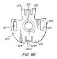
- the outer retaining ringis initially formed from a blank of sheet material, e.g. spring steel or the like, having a cruciform shape that includes a face portion or simply a central opening wherein the radiating arms of the cruciform blank are disposed about the face portion or central opening to define a frustro-conical ring or cup.
- the ring so formedis provided with blanked out or die cut tangs to define outwardly bent locking tangs.
- the trailing edge of the frustro-conical ringprovides for electrical grounding.
- the frustro-conical ring so formedalso has a slot adapted to receive the retaining lug when the retaining ring is fitted onto the outlet end portion of the connector body so that the free or trailing ends of the ring define a ground or edge that engages the inner periphery of the knockout hole of an electric box for effecting positive electrical continuity and grounding.
- the cruciform armsare arranged to be folded relative to the central opening or face forming portion that circumscribes the central opening, to define a unitary frustro-conically shaped cup-like member or ring to compliment or be fitted onto the outlet end portion of the connector body.
- the retaining ring thus formedis fitted over or onto the outlet end portion whereby the retaining slot formed in the ring is adapted to receive the complementary retaining lug formed on the surface of the outlet end portion for retaining the ring on the outlet end portion of the connector body.
- the connector assemblycan be readily inserted through the knockout hole of an electric box wherein the locking tangs will initially be flexed inwardly to pass through the knock-out hole of an electric box, and then spring outwardly to lock the connector assembly to the electric box with the trailing or grounding edge of the retaining ring or arms being inherently biased so as to be urged against the internal periphery of the knockout hole due to the conical configuration of the retaining ring to effect a positive electric ground as a result of the inherent resiliency of the respective grounding edges and the material from which they are formed.
- This inventionfurther contemplates providing the inlet end of the connector with an improved wire or conductor retainer which is uniquely formed for positively securing thereto a wire conductor by merely inserting the wire conductor into the inlet end of a connector.
- the arrangementis such that the wire conductor is prohibited from being unintentionally separated therefrom.
- the inner wire conductor retaineris preferably formed of a blank of spring metal material to define a spring finger having one end thereof fixedly secured to an external portion of the inlet end of a connector body, and having the other end of the spring finger extending through an opening formed in the connector body so as to be disposed at an angle to the longitudinal axis of the inlet end portion whereby a wire conductor is retained within the inlet end of a connector in a manner to prohibit any unintentional separation.
- a further embodiment of the disclosed inventionmay utilize an external circular shaped snap fit locking ring for circumscribing the outlet end of the connector body.
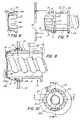
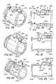
- FIG. 1is an exploded perspective view of the electrical connector assembly.
- FIG. 2is a plan view of the blank from which the outer retaining ring of the present invention is formed.
- FIG. 3is a detail front view of the outer retainer ring.
- FIG. 4is a detail top plan view of the outer retainer ring of FIG. 3 .
- FIG. 5is a detail end view of FIG. 4 .
- FIG. 6is a sectional view of the outer retainer ring taken along line 6 - 6 on FIG. 3 .
- FIG. 7is a side view of the connector assembly illustrating the alignment thereof relative to the knockout opening of an electric box.
- FIG. 8is a section side view illustrating the connector assembly secured to an electric box, taken along line 8 - 8 on FIG. 10 .
- FIG. 9is a sectional side view taken along line 9 - 9 on FIG. 10 and rotated 90°.
- FIG. 10is a fragmentary front view of the connector assembly secured to an electric box as viewed from the electrical box.
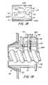
- FIG. 11is an exploded perspective view of a modified form of the invention.
- FIG. 12is a sectional side view of the modified form of the invention of FIG. 11 .
- FIG. 13is a top plan view of the blank from which the internal wire conductor retainer is formed.
- FIG. 14is a fragmentary top view of a portion of the blank forming the inner retainer sleeve or ring.
- FIG. 15is an end view of the inner wire conductor retainer ring or sleeve.
- FIG. 16is a top view of the inner retainer ring or sleeve of FIG. 15 .
- FIG. 17is a section view taken along 17 - 17 on FIG. 16 .
- FIG. 18is a side view of the inner retainer ring or sleeve.
- FIG. 19is a sectional side view of still another embodiment.
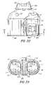
- FIG. 20is a perspective view of a further embodiment of the invention.
- FIG. 21is an exploded perspective view of the embodiment of FIG. 20 .
- FIG. 22is a top plan view of the embodiment of FIG. 20 having parts thereof broken away.
- FIG. 23is a sectional view taken along line 23 - 23 on FIG. 22 .
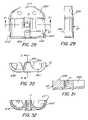
- FIG. 24is the interior plan view of one section of the connector housing of the embodiment illustrated in FIG. 20 .
- FIG. 25is an outer end view of FIG. 24 .
- FIG. 26is an end view of the connector housing section of FIG. 24 .
- FIG. 27is a sectional view of the housing section taken along line 27 - 27 on FIG. 26 .
- FIG. 28is an inside plan view of the complementary housing section of the embodiment illustrated by FIG. 20 .
- FIG. 29is an end view of FIG. 28 .
- FIG. 30is an inlet end view of FIG. 28 .
- FIG. 31is a sectional view taken on line 31 - 31 on FIG. 30 .
- FIG. 32is a sectional view taken on line 32 - 32 on FIG. 28 .
- FIG. 33is a perspective exploded view of a further embodiment of the invention.
- FIG. 34is a top plan view of the blank from which the wire retainer device is formed.
- FIG. 35is a side view of the blank of FIG. 34 .
- FIG. 36is a side view of the blank of FIGS. 34 and 35 as formed to define wire retainer.
- FIG. 37is a top view of a slightly modified form of a wire retainer.
- FIG. 38is a perspective view of the connector body embodying the invention of FIG. 33 .
- FIG. 39is a side view of FIG. 38 .
- FIG. 40is a top plan view of FIG. 39 .
- FIG. 41is a left end view of FIG. 39 .
- FIG. 42is a right end view of FIG. 39 .
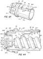
- FIG. 43is a perspective view of the assembled connector embodiment shown in FIG. 33 .
- FIG. 44is a side sectional view of the connector assembly of FIG. 43 .
- FIG. 45is an exploded perspective of another modified form of the invention.
- FIG. 46is a perspective view similar to FIG. 45 illustrated in the assembled position.
- FIG. 47is a side view of FIG. 46 .
- FIG. 48is a side view of the connector assembly of FIG. 47 in engagement with a pulling tool of the present invention.
- FIG. 49is a bottom plan view of FIG. 48 .
- FIG. 50is a side elevation view illustrating the initial insertion of the connector assembly of FIG. 45 into a knockout hole of an electric box.
- FIG. 51is a side elevation view similar to FIG. 50 illustrating the connector assembly fully seated and locked in the knockout hole of an electric box which is affected by the lever action of the operating tool.
- FIG. 52is a perspective view of the operating tool embodiment for facilitating the locking of an electrical connector to an electric box.
- FIG. 53is a plan view of the tool of FIG. 52 .
- FIG. 54is an edge view of FIG. 53 .
- FIG. 55is a bottom plan view of FIG. 54 .
- FIG. 56is a left end view of FIG. 55 .
- FIG. 57is a perspective view of a slightly modified tool.
- FIG. 58is a left end view of FIG. 57 .
- FIG. 59is a perspective view of still another modified operating tool.
- FIG. 60is an exploded perspective view of another modified form of the invention.
- FIG. 61is a section side view of the embodiment of FIG. 60 illustrating the manner for effecting the connection of the modified embodiment of FIG. 60 to a knock-out hole of an electric box.
- FIG. 62is a section side view similar to FIG. 61 illustrating the connector assembly of FIG. 61 in locked position relative to an electric box.
- FIG. 63is an assembled view of FIG. 1 connector
- FIG. 64is a front end view of the frustro-conical retainer ring of the embodiment illustrated in FIG. 60 .
- FIG. 65is a fragmentary detail sectional side view of a modified auxiliary tang construction.
- FIG. 66is a plan view of a modified blank for forming a frustro-conical snap fit retaining ring.
- FIG. 67is an exploded perspective view of still another modification of the invention.
- FIG. 68is a top plan view of the embodiment of FIG. 67 .
- FIG. 69is a right end view of FIG. 68 .
- FIG. 70is a sectional view taken along line 70 - 70 on FIG. 69 .
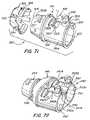
- FIG. 71is a perspective of a partially exploded view of another embodiment of the disclosed invention.
- FIG. 72is a perspective view of another modified form of the disclosed invention illustrated without the outer retainer ring.
- FIG. 73is a perspective exploded view of a further embodiment of the invention.
- FIG. 74is a side assembled view of FIG. 73 .
- FIG. 75is a side sectional view taken essentially along line 75 - 75 of FIG. 74 .
- FIG. 76is a right end view of FIG. 74 .
- FIG. 77is a perspective exploded view of a modified form of the invention.
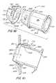
- FIG. 78is a perspective view of another embodiment of the invention.
- FIG. 79is a cross sectional view of FIG. 78 .
- FIG. 80is a perspective view of another modified embodiment.
- FIG. 81is a cross sectional view of FIG. 80 .
- FIG. 82is a perspective view of another modified embodiment.
- FIG. 83is a cross sectional view of FIG. 82 .
- the connector assembly 10includes a connector body 11 , which is usually formed of metal casting, e.g. zinc or other suitable metallic alloy.
- the connector body 11is formed with an inlet end portion 11 A and an outlet end portion 11 B and having a bore 12 extending therethrough.
- a radially outwardly extending flange 13which functions as a stop to limit the amount that the connector body 11 may be inserted through the knockout hole 14 of an electric box 15 , as noted in FIG. 8 .
- the outer surface S of the outlet end portion 11 Bslopes, tapers or converges toward the outlet opening 16 whereby the outer surface S of the outlet end portion 11 B has a generally frustro-conical configuration.
- Formed on the surface S of the outlet end portion 11 Bis an outwardly projecting retainer lug 17 .
- two such lugs 17are shown disposed 180° apart about the outer circumference of the outlet end portion 11 B.
- the connector assembly 10also includes a snap fit retaining ring 18 .
- the retaining ring 18is integrally formed from a blank 19 of spring steel material.
- the blank 19is initially formed or stamped to define a generally cruciform shape.
- the cruciform shapeis provided with a face portion 20 having central opening or hole 20 A and having four generally radially extending arms defining two pairs of oppositely disposed arms AA and BB.
- the opposed pair of arms AAare each provided with a retaining slot 21 .
- the opposed pair of arms BBare blanked or formed to define a locking tang 22 and to either side thereof the trailing edge defines an electrical grounding tang 23 , 23 .
- the locking tang 22is slightly shorter than the adjacent grounding tangs 23 , 23 . The arrangement is such that the free end of the locking tangs 22 are sprung outwardly and formed so as to engage the inside surface of the electric box 15 in the assembled portion, as best seen in FIG.
- the free ends or trailing edges of the frustro-conical ringdefine the grounding tangs 23 that are biased in engagement with the internal periphery of the knockout hole 14 .
- the free edges or ends 24 , 24 of arms A,A in the assembled positionwill also function as electrical grounding tangs, as noted in FIG. 8 .
- the respective arms A,A and B,Bare subjected to a series of progressive bending dies which will gradually bend the respective arms about a foldline f, which defines the face or front portion 20 , whereby arms A,A and B,B form a cup having circumscribing frustro-conical or outwardly flaring sides to define a frustro conical ring 18 which complements the conical surface S of the leading or outlet end portion 11 B, as seen in FIG. 1 .
- the locking tangs 22are cantileverly and outwardly bent or displaced relative to the surface of the frustro-conical ring at a slightly greater outwardly angle or slope than the adjacent grounding edge or tangs 23 and the slope of arms A,A.
- the retaining ring 18With the retaining ring 18 so formed, it can be readily fitted onto the outlet end portion 11 B whereby the inherent resiliency of the arms A,A will cause the retainer slots 21 to snap fit onto the retaining lug 17 when slots 21 are placed in alignment with lugs 17 .
- the arrangementis such that the retainer ring 18 will be firmly and positively secured to the outlet end portion 11 B as seen in FIG. 8 . Yet, due to the inherent resiliency of the material of the retaining ring 18 , it can be easily detached from the outlet end portion 11 B when removal is desired, without destroying the ring 18 by lifting arms A,A free of the retaining lugs 17 .
- the opening 20 Amay be enlarged to the diameter of the foldline f, in which case the arms A,A and B,B may be gradually bent about the periphery of the enlarged opening, thereby eliminating the face portion 20 .
- the connector assembly 10can be readily secured to an electric box 10 by simply aligning the assembly 10 with a knockout hole 14 , as best seen in FIG. 7 , and inserting the leading or outlet end portion into the knockout hole 14 until the flange 13 engages the outer side of the electric box 15 . In doing so, the tangs 22 , 23 and the free ends 24 of arms A,A, respectively, will depress inwardly to permit insertion of the assembly 10 . When the assembly is fully seated in the knockout hole 14 , the locking tangs 22 will normally spring outwardly to secure the assembly 10 to the electric box 15 , as noted in FIG. 9 .
- the inherent resiliency of the grounding tangs 23 , 23 and the free ends or edges 24 of arms A,Aare normally biased in engagement with the internal periphery of the knockout hole 14 to ensure a positive electrical ground with the electric box 15 .
- the engagement of the free ends 24 of arms A,A and grounding tangs 23 , 23 against the inner periphery of the knockout hole 14as noted in FIG. 8 , further ensures the firm securing of the retaining slot 21 with the retaining lugs 17 , so as to prohibit any disengagement of the outer retaining ring 18 from the connector body 11 .
- the wire conductor 25may be secured to the connector assembly 10 either before or after the assembly 10 has been secured to the electric box 15 .
- the conductor wire 25is simply inserted into the inlet end portion 11 A and secured in position by a suitable securing means.
- the securing meansis illustrated as a set screw 26 .
- other forms of securing meansmay be used, than the set screw 26 illustrated.
- the snap fit retaining ring 18can be simply formed from a cruciform shaped blank 19 whereby the opposed radially extending arms A,A and B,B can be readily formed into a cup having a generally frustro-conically shaped sidewalls complementing the slope of the outlet end portion 11 A, and whereby the outer retainer ring 18 can be readily secured to the connector body simply by the inter-engagement of slots 21 with its complementary lugs 17 .
- the outer retainer ring 18is positively secured to the connector body in a manner to prohibit any unintentional separation.
- the tangs 22 and 23which are formed integral with ring 18 , are shaped and formed so that the locking tangs 22 secure the assembly 10 to an electric box 15 while the grounding tangs 23 ensure a positive electrical ground of the assembly 10 with the associated electric box 15 .
- FIGS. 11 to 19illustrate various views of a modified form of the invention which are described in application Ser. No. 11/100,250 filed Apr. 6, 2005 for Snap In Electrical Connector Assembly With Unidirectional Wire Conductor Ring, which is incorporated by reference herein.
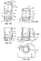
- FIGS. 20 to 32are directed to a further modification of the disclosed invention.
- the connector assembly 60includes a housing or connector body 61 having an outlet end 61 A and an inlet end 64 connected to the outlet end 61 A by a transition section 68 , 68 A, preferably formed as casting of any suitable metal or alloy material, e.g. zinc, aluminum and the like. While the inlet end 64 of the connector body 61 is illustrated as a duplex inlet end, it will be understood that the inlet end may be formed to accommodate more than two separate wire conductors, cables or the like.
- outlet end 61 A and the external frustro-conical ring 76 circumscribing the outlet end 61 Aare similar in structure hereinbefore described with respect to FIGS. 1 to 10 .
- the connector assembly 60can be readily secured to an electric box or panel simply by inserting the leading or outlet end 61 A through a knockout hole of a panel or electrical box so as to be readily secured thereto with a snap fit as hereinbefore described.
- the respective wire conductors or cables 80can be readily attached to the trailing or inlet end of the connector assembly 60 with a simple snap fit, as described in application Ser. No. 11/100,250 filed Apr. 6, 2005, which is incorporated by reference herein.
- the connector assemblies disclosed in FIGS. 1 to 32utilize a frustro conically shaped outer retainer ring which is uniquely secured to the leading end of a connector body, with securing tangs and grounding tangs arranged to effect both a positive securement of the connector assembly to a knockout hole of an electric box or panel and a positive electrical ground.
- the disclosed embodimentsinclude a trailing or inlet end constructed to receive an associated wire or conductor retainer in each inlet end for securing a wire conductor thereto by a snap fit inlet end of the connector body.
- the described electrical connector bodiesmay include one or more wire receiving chambers formed in the inlet end thereof, depending upon the number of wire conductors one may wish to connect to the inlet end of a connector body.
- FIGS. 33 to 44illustrate a further modification of the invention.
- the connector assembly 81includes a connector body 81 A having an outer frustro conical external snap-fit retainer ring 82 , a wire retainer device 83 , and an optional plastic electrical insulating end ring insert 84 .
- the outlet end 81 B of the connector body 81 A and the external frustro-conical retainer ringis similar in structure and function as hereinbefore described.
- a more detailed description of the embodiments 33 to 44are set forth in application Ser. No. 11/151,374 filed Jun. 13, 2005, which is incorporated herein by reference.
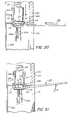
- FIGS. 45 to 51illustrate further embodiments of the invention.
- the embodiments of FIGS. 45 to 51are directed to a snap-fit electrical connector assembly 100 which is particularly suitable for attaching an electric cable or conductor 101 to an electric box 102 which is disposed in a finish wall structure 103 , and which is rendered the subject matter of an application Ser. No. 11/258,990 filed Oct. 26, 2005.
- the installeris generally unable to access a snap-fit connector so as to apply the necessary pulling or pushing force necessary to insert and lock a snap-fit connector assembly, e.g. 100 , in a knockout opening of the electric box 102 .
- the installergenerally utilized a connector having a threaded outlet end which could be readily passed through a knockout hole of an electric box, which could then be secured by threading thereon a lock nut from within the box opening, which is both difficult and time consuming.
- the connector assembly 100includes a connector body 104 having a leading end or outlet end 105 and a trailing or inlet end 106 .
- the connector bodymay be formed as a metal casting of a suitable material, e.g. a zinc alloy, having a bore 107 extending therethrough. Circumscribing the connector body 104 between the outlet end 105 and the inlet end 106 is a radially outwardly extending stop flange 108 .
- the outer surface S of the outlet end 105tapers or converges inwardly toward the central axis of the connector body 104 and the outlet opening 109 .
- a frustro-conical snap-fit retainer ring 110Complementing the slope or taper of the outer surface S of the outlet end 105 is a frustro-conical snap-fit retainer ring 110 which is similar in structure hereinbefore described with respect to FIGS. 1 to 4 , except that the width of the retaining slot 111 adapted to receive the retaining lug 112 is enlarged, as compared to the width of retaining slot 21 as hereinbefore described. As best seen in FIGS. 47 and 48 , the retaining slot 111 has a width which is greater than the width of the retainer lug 112 adapted to be received in slot 111 in the assembled position, as best illustrated in FIGS. 46 and 47 .
- the structure of the retainer ring 110is similar to the construction of retainer ring 18 hereinbefore described with respect to the embodiments illustrated, for example in FIGS. 1 to 4 , and which need not be repeated.
- FIGS. 45 to 51A more detailed description of FIGS. 45 to 51 is set forth in application Ser. No. 11/258,990 filed Oct. 6, 2005, which is incorporated herein by reference.
- FIGS. 60 to 64illustrate a further embodiment of the invention.
- the connector assembly 200comprises a connector body 201 and a modified outer frustro-conical retainer ring 202 as described in a co-pending application Ser. No. 11/364,435 filed Feb. 28, 2006, for Snap Fit Electrical Connector Assembly For Facilitating The Electric Connector Assembly To An Electric Box, which is incorporated by reference herein.
- FIGS. 60-64While the embodiment of the connector assembly 200 of FIGS. 60-64 is illustrated without any electrical conductor retaining means associated with the inlet end portion 201 A of the connector body 201 , it will be understood that the inlet end portion 201 A may be fitted with any of the wire conductor retainer means as are described and illustrated herein, the descriptions of which need not be repeated.
- FIGS. 67 to 70illustrate a further embodiment of the invention.
- the connector assembly 300as illustrated in FIGS. 67 and 68 , includes a connector body 301 formed as a unitary casting of any suitable metal or alloy, e.g. zinc and the like. The form of the casting is somewhat similar to that shown in FIG. 20 .
- the embodiment of FIG. 67differs from that of FIG. 20 in that connector body 301 is formed as a unitary casting rather than as separable parts as illustrated in FIG. 20 .
- a more detailed description of the embodiment of FIGS. 67 to 70is set forth in application Ser. No. 11/403,099 filed Apr. 12, 2006, for Snap Fit Electrical Connector Assembly With Frustro-Conical Retainer Ring And Internal Unidirectional Snap Fit Wire Conductor Retainer, which is incorporated by reference herein.
- FIG. 71illustrates a further embodiment of the invention.
- the electric connector assembly 320includes a connector body 321 that has an inlet end portion 321 A and a connected outlet end portion 321 B. Intermediate between the inlet end portion 321 A and the outlet end portion 321 B there is provided a radially outwardly extending flange 322 which serves as a stop to limit the portion of the connector assembly 320 that may be inserted through a knock out hole of an electric box, as hereinbefore described.
- the inlet end portion 321 Adefines an inlet opening 323 and the outlet end portion defines an outlet opening 324 that defines the opposed ends of a bore 325 that extends through the connector body between openings 323 and 324 .
- the outer surface S of the outlet end portion 321 Bslopes or tapers downwardly from the stop flange 322 toward the outlet opening 324 , as hereinbefore described.
- Circumscribing the outer surface S of the outlet end portion 321 Bis a frustro-conical external snap fit ring 326 similar to that herein before described with locking tangs 334 and grounding tangs 335 .
- the frustro-conical retainer ring 326is retained on the sloping surface S of the outlet end portion by the retaining lugs 327 on the outlet end portion engaging the complimentary slots 328 formed in the frustro-conical surface of the outer retaining ring 326 as hereinbefore noted.
- the retaining lugs 327 and complementary slots 328act as a means for retaining the frustro-conical retaining ring 326 on the outlet end portion 321 B.
- a simplified electrical conductor retainer 332for securing an armor shielded electric wire, cable or other electrical conductor or wire for securing the same connector body is provided.
- the inlet end portion 321 A of the connector body 321is provided with a window or opening 330 which is disposed in communication with the bore 325 extending through the connector body 321 .
- a raised fastening mount or boss 331Projecting outward from the inlet end portion adjacent the inlet opening 323 is a raised fastening mount or boss 331 having a generally flat upper surface 331 A similar to that shown in FIG. 73 .
- the conductor retainer 332is formed of an elongated blank of spring metal, e.g. spring steel or other suitable resilient material, which is angularly bent along an intermediate fold or bend line L 1 , wherein the angularly bent end 332 B is projected through the window or opening 330 so as to extend into the bore 325 for engaging and retaining an electrical conductor as shown in the embodiment of FIG. 75 .
- the other end 332 A of the conductor retaineris detachably secured to the mount or boss 331 by means of a suitable fastener, e.g. a set screw.
- the free end 332 Cmay be provided with an arcuate configuration as best seen in FIGS.
- the portion of the conductor retainer projecting through the window or opening 330is bent at an angle so that the free end thereof is directed in the direction of the outlet opening 324 of the connector body 321 .
- the arrangementis such that the wire conductor or armored shield conductor can be readily inserted into the inlet opening 323 in a unidirectional manner so that when the conductor is gripped by the free end 332 C of the wire retainer 321 , the wire conductor cannot readily be pulled out of the connector body without actively removing the inherent resisting force imparted by the conductor retainer onto the electric conductor.
- the described electric connector assembly 320can be readily secured to a knock out hole of an electric box simply by inserting the outlet end with the attached frustro-conical retainer ring through the knock out hole so that upon seating the assembly in the knock out hole causes the locking tangs 334 of ring 326 to spring outwardly and lock the connector assembly to the electric box.
- the electric conductorcan be simply attached to the connector simply by inserting the electric conductor into the inlet end portion wherein it is automatically gripped by the free end 332 C in a manner to prohibit any unintentional separation of the electrical conductor from the associated connector assembly.
- the wire retainerconstitutes a simplified structure which can be readily formed simply from an elongated blank of spring steel or the like, which need only be bent intermediate the length thereof and which is externally mounted on the connector body.
- the simplified described conductor retainerenhances not only the ease of manufacture and assembly, the simplified structure further minimizes the amount and cost of material otherwise required by the known connectors capable of achieving the ease of use and utility of the invention disclosed in the embodiments described.
- FIG. 72illustrates an embodiment of the invention as described with respect to the embodiment of FIG. 71 , except that the invention is described as applied to a duplex type of an electrical connector assembly 340 .
- the embodiment of FIG. 72is directed to an electrical connector assembly having a connector body 341 that includes a trailing or inlet end portion 341 A that is shaped so as to define at least two passageways 342 , 343 , having inlet openings 342 A, 343 A disposed in side by side relationship. While only two passages 342 , 343 are illustrated, it will be understood that more than two passageways may be disposed in side by side relationship, depending upon the number of wire conductors one wishes to attach to a given connector body.
- the connector body 341also includes an outlet end portion 344 similar to outlet end portion 321 B of FIG. 71 , and need not be further described. It will be understood that the outlet end 344 is constructed so as to accommodate an outer retainer ring similar to the retainer ring 326 described with respect to FIG. 71 , and as hereinbefore described.
- the embodiment of FIG. 72includes a transition section 345 that connects the duplex inlet end portion 341 A to the outlet end portion 344 , and in communication therewith.
- the connector body 341 of FIG. 72also includes a retainer opening or window 342 A, 343 A disposed in communication with its corresponding passageway 342 , 343 .
- Connected to the connector body 341are conductor retainers 343 B, 343 B which are similar in structure and function as hereinbefore described with respect to FIG. 71 .
- the conductor retainers 343 B, 343 Bare secured at one end externally of the connector inlet end portion 341 A on a mount or boss 346 , 347 in the same manner as hereinbefore described.
- the structure and function of the connector assembly 340is similar to that described with respect to the embodiment of FIG. 71 .
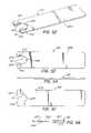
- FIG. 73illustrates another embodiment of the invention.
- the connector assemblyincludes a connector body 353 having an inlet end portion 350 A and an outlet end portion 350 B and a bore 351 extending therethrough.
- a stop flange 352extends radially outwardly of the connector body 353 and defines the inlet end portion 350 A from the outlet end portion 350 B.
- Circumscribing the outlet opening 354 of the connector body 353is a radially outwardly extending outlet flange 355 .
- a shoulder 356 356 AAdjacent to each of said stop flange 352 and outlet end flange 355 there is provided a shoulder 356 356 A, wherein the shoulders 356 , 356 A have an outer diameter which is less than the outer diameter of the stop flange 352 and outlet end flange 355 .
- the connector assembly 350is further provided with a window or opening 358 formed in the inlet end portion 350 A similar to that hereinbefore described.
- a conductor retainer 359which is similar in structure and function as the conductor retainer hereinbefore described with respect to the embodiment of FIG. 71 .
- the wire or conductor retainer 359is secured to a mount or boss 331 A by means of a suitable fastener or set screw 360 whereby the free end 359 A of the conductor retainer 359 is directed through the window or opening 358 to engage the electrical conductor 361 , as hereinbefore described.
- FIG. 77illustrates a duplex version of the embodiment disclosed in FIG. 76 .
- the embodiment of FIG. 77is directed to an electrical connector assembly 370 that includes a connector body 371 having a duplex inlet end portion 371 A, an outlet end portion 371 B, and an interconnected transition section 371 C interposed between the inlet end portion 371 A and outlet end portion 371 B.
- the inlet end portionis formed and illustrated as having a pair of side by side passageways 372 and 373 extending through the inlet portion 371 A, each passageway 372 and 373 being adapted to receive an electric conductor of the type hereinbefore described.
- the respective passageways 372 , 373lead to the interior of the transition section 371 C wherein the wires of the electric conductor are directed to and out of the inlet end portion 371 B, as best noted in FIG. 20 .
- the inlet end portion 371 Amay be construed to have more than two passageways 372 , 373 , with or without partition walls, disposed in side by side relationship, depending upon the number of individual wire conductors one desires to connect to a given inlet end portion of a connector body.
- the outlet end portion 371 Bis similar to the outlet end portion 350 B of FIG. 73 , which is arranged to receive an outer retainer ring 374 , which is structurally and functionally as that described with respect to the embodiment of FIG. 73 , and need not be repeated.
- FIG. 77includes an electrical conductor retainer means 375 , 376 and an associated window or opening 377 , 378 for each passageway 373 , 374 .
- the respective electrical retainer means 375 , 376are identical in structure and function to that hereinbefore described with respect to the electrical conductor means described with respect to the embodiment of FIG. 73 .
- FIGS. 78 and 79are directed to another modified form of the invention.
- the connector assembly 380includes a connector body 382 having an inlet end portion 380 A and an outlet end portion 380 B wherein the inlet end portion 380 A has an outer diameter “D” which is greater than the outer diameter “d” of the outlet end portion 380 B.
- Douter diameter
- the need for a stop flange, as hereinbefore described,is rendered unnecessary as the leading edge 381 of the inlet end portion 380 A can function as the stop or limit the distance the connector body 382 may be inserted through a knock out hole of an electric box or panel.
- the outlet end portion 380 Bis provided with a radially outwardly extending flange 383 that circumscribes the outlet end opening 384 . Disposed between the leading edge 381 of the inlet end portion 380 A and the outlet opening flange 383 are a pair of spaced apart shoulders 385 , 386 , which extend radially outwardly a distance that is less than that of the leading edge 381 and the outlet opening flange 383 which define therebetween a circumscribing groove or space “g”.
- a circular snap fit retainer ring-like ring 374as shown and described with respect to FIG. 77 is disposed on the shoulders 385 , 386 and is retained thereon between the outlet opening flange 383 and the leading edge 381 .
- the connector assembly 380 of FIGS. 78 and 79is also provided with a simplified electric conductor retainer means that includes an elongated blank of spring metal 387 which is formed as hereinbefore described in FIGS. 73 to 77 and which is affixed at one end to the external surface of the inlet end portion by a set screw or other suitable fastening means 388 , as hereinbefore described.
- the inlet end portion 380 Amay be provided with a series of circumferential voids or spaces 390 formed within the thickness of the inlet end portion.
- FIGS. 80 and 81illustrate a further embodiment of the invention.
- This form of the inventionis similar to that described with respect to the embodiment of FIGS. 78 and 79 , except that the connector assembly 395 includes an inlet end portion 395 A that is formed with a radially outward projecting protective wall 396 that circumscribes the window or opening 397 on three sides.
- the conductor retainer 398is disposed within the perimeter of the protective wall 396 .
- the construction and function of the connector assemblyis similar to that described in FIGS. 78 and 70 , and need not be repeated.
- FIGS. 82 and 83are directed to a further modification of the invention.
- the connector assembly 400includes a connector body 401 having an inlet end portion 401 A, an outlet end portion 401 B and having a bore 402 extending therethrough.
- a radially outwardly extending flange 403circumscribes the connector body intermediately thereof to define the inlet end portion 401 A from the outlet end portion 4013 .
- Circumscribing the outlet end portion 401 Bare external threads 404 which are adapted to receive a lock nut (not shown) for securing the connector assembly to a knock out hole of an electric box.
- a projecting boss or fastening mount 405Formed on the exterior end of the inlet end portion 401 A is a projecting boss or fastening mount 405 , as hereinbefore described.
- a conductor retainer 406mounted on the exterior fastening mount or boss 405 is a conductor retainer 406 similar in structure and function as hereinbefore described with respect to each of the embodiments disclosed herein.
- the free end 406 Ais angularly bent relative to the mounted end 406 B so as to extend through a window or opening 407 , as hereinbefore described.
- each of the described connector assembliesare constructed so that the embodiments can be readily and quickly connected to a knock out hole of an electric box with a simple snap fit connection.
- All of the respective embodimentsalso have in common a simplified externally mounted wire or conductor retainer in the form of a flat spring which can be readily secured to the exterior portion of the connector body adjacent the inlet by means of a simple fastener, which flat spring is shaped to have its other free end extending through a window or opening so as to extend into the inlet end portion of the connector body in a manner whereby a wire conductor can be readily unidirectionally inserted into the inlet end portion and simultaneously secured therein in a manner that prohibits any unintentional separation or pull out of the wire conductor from the connector assembly, all without the need of any extraneous tools.
- FIGS. 82 and 83can be secured to a knock out hole by means of a conventional lock nut while attaining the benefits of the simplified wire retainer means as described herein.
Landscapes
- Engineering & Computer Science (AREA)
- Architecture (AREA)
- Civil Engineering (AREA)
- Structural Engineering (AREA)
- General Engineering & Computer Science (AREA)
- Mechanical Engineering (AREA)
- Details Of Connecting Devices For Male And Female Coupling (AREA)
- Connector Housings Or Holding Contact Members (AREA)
Abstract
Description
Claims (16)
Priority Applications (2)
| Application Number | Priority Date | Filing Date | Title |
|---|---|---|---|
| US12/319,304US7645947B2 (en) | 2004-09-13 | 2009-01-06 | Electrical connector with outer retainer ring and internal unidirectional conductor retainer |
| US12/322,276US8143535B2 (en) | 2004-09-13 | 2009-01-30 | Electrical connector assembly with enhanced grounding |
Applications Claiming Priority (9)
| Application Number | Priority Date | Filing Date | Title |
|---|---|---|---|
| US10/939,619US6916988B1 (en) | 2004-07-12 | 2004-09-13 | Electrical connector with frustro conical snap fit retaining ring |
| US11/100,250US7064272B2 (en) | 2004-09-13 | 2005-04-06 | Snap in electrical connector assembly with unidirectional wire conductor retainer ring |
| US11/151,374US7075007B2 (en) | 2004-09-13 | 2005-06-13 | Snap fit electrical connector assembly with conical outer snap fit retainer and one or more internal snap fit wire retainers |
| US11/258,990US7057107B2 (en) | 2004-09-13 | 2005-10-26 | Snap fit electrical connector assembly with conical outer snap fit retainer and externally mounted internal wire retainer |
| US11/364,435US7205489B2 (en) | 2004-09-13 | 2006-02-28 | Snap fit electrical connector assembly with operating tool for facilitating the connection of a connector assembly to an electrical box |
| US11/400,606US7154042B2 (en) | 2004-09-13 | 2006-04-07 | Electrical connector with snap fit retainer ring constructed to enhance the connection of the connector to an electrical box |
| US11/403,099US7151223B2 (en) | 2004-09-13 | 2006-04-12 | Snap fit electrical connector assembly with outer frustro conical retainer ring and internal unidirectional snap fit wire conductor retainer |
| US11/501,131US7488905B2 (en) | 2004-09-13 | 2006-08-08 | Electrical connector with outer retainer ring and internal unidirectional conductor retainer |
| US12/319,304US7645947B2 (en) | 2004-09-13 | 2009-01-06 | Electrical connector with outer retainer ring and internal unidirectional conductor retainer |
Related Parent Applications (1)
| Application Number | Title | Priority Date | Filing Date |
|---|---|---|---|
| US11/501,131ContinuationUS7488905B2 (en) | 2004-09-13 | 2006-08-08 | Electrical connector with outer retainer ring and internal unidirectional conductor retainer |
Related Child Applications (1)
| Application Number | Title | Priority Date | Filing Date |
|---|---|---|---|
| US12/322,276Continuation-In-PartUS8143535B2 (en) | 2004-09-13 | 2009-01-30 | Electrical connector assembly with enhanced grounding |
Publications (2)
| Publication Number | Publication Date |
|---|---|
| US20090120687A1 US20090120687A1 (en) | 2009-05-14 |
| US7645947B2true US7645947B2 (en) | 2010-01-12 |
Family
ID=46324882
Family Applications (2)
| Application Number | Title | Priority Date | Filing Date |
|---|---|---|---|
| US11/501,131Expired - LifetimeUS7488905B2 (en) | 2004-09-13 | 2006-08-08 | Electrical connector with outer retainer ring and internal unidirectional conductor retainer |
| US12/319,304Expired - LifetimeUS7645947B2 (en) | 2004-09-13 | 2009-01-06 | Electrical connector with outer retainer ring and internal unidirectional conductor retainer |
Family Applications Before (1)
| Application Number | Title | Priority Date | Filing Date |
|---|---|---|---|
| US11/501,131Expired - LifetimeUS7488905B2 (en) | 2004-09-13 | 2006-08-08 | Electrical connector with outer retainer ring and internal unidirectional conductor retainer |
Country Status (1)
| Country | Link |
|---|---|
| US (2) | US7488905B2 (en) |
Cited By (9)
| Publication number | Priority date | Publication date | Assignee | Title |
|---|---|---|---|---|
| US7824213B1 (en)* | 2009-07-27 | 2010-11-02 | Hubbell Incorporated | One-piece electrical cable connector having a retaining spring |
| US20110314657A1 (en)* | 2010-06-29 | 2011-12-29 | Edwin Ramgattie | Device for Deterring Unwanted Removal of Cable from Conduit |
| USD666153S1 (en)* | 2011-07-18 | 2012-08-28 | Bridgeport Fittings, Inc. | Flexible metal conduit connector with external bonding connector |
| US9929551B2 (en) | 2015-11-02 | 2018-03-27 | Hubbell Incorporated | Electrical box cable connector |
| US20190109410A1 (en)* | 2017-10-06 | 2019-04-11 | Hubbell Incorporated | Cable connector |
| US10263404B2 (en) | 2015-12-07 | 2019-04-16 | Hubbell Incorporated | Electrical box cable clamp |
| US10547164B2 (en) | 2014-05-02 | 2020-01-28 | Sigma Electric Manufacturing Corporation | Connectors and methods for making and using the same |
| US10644491B2 (en) | 2017-10-13 | 2020-05-05 | Hubbell Incorporated | Electrical box cable connector |
| US11387639B2 (en) | 2018-07-11 | 2022-07-12 | Hubbell Incorporated | Electrical box cable connector |
Families Citing this family (29)
| Publication number | Priority date | Publication date | Assignee | Title |
|---|---|---|---|---|
| CA2684934A1 (en)* | 2007-05-23 | 2008-11-27 | Tm4 Inc. | Electrical connector |
| US20080296061A1 (en)* | 2007-05-30 | 2008-12-04 | Kerr Jr Jack Russell | Connector for an electrical junction box |
| USD596578S1 (en)* | 2007-09-21 | 2009-07-21 | Bridgeport Fittings, Inc. | Electrical connector |
| US10468863B1 (en) | 2008-04-03 | 2019-11-05 | Arlington Industries, Inc. | Duplex electrical connector with one-piece connector body |
| CN201202720Y (en)* | 2008-05-12 | 2009-03-04 | 钛积创新科技股份有限公司 | Stud positioning device |
| US8901441B2 (en)* | 2008-10-08 | 2014-12-02 | Sigma Electric Manufacturing Corporation | Conduit connector and methods for making and using the same |
| US8857039B2 (en) | 2010-02-19 | 2014-10-14 | Sigma Electric Manufacturing Corporation | Electrical box conduit connectors and methods for making and using the same |
| US10601189B1 (en) | 2010-10-29 | 2020-03-24 | Bridgeport Fittings, Llc | Snap-in electrical connector |
| US8791374B1 (en) | 2010-10-29 | 2014-07-29 | Bridgeport Fittings, Inc. | Snap-in electrical connector |
| US9705296B1 (en)* | 2010-10-29 | 2017-07-11 | Bridgeport Fittings, Inc. | Snap-in electrical connector |
| US8803008B2 (en) | 2011-03-03 | 2014-08-12 | Sigma Electric Manufacturing Corporation | Conduit connector and methods for making and using the same |
| US9231388B2 (en) | 2011-09-01 | 2016-01-05 | Sigma Electric Manufactruing Corporation | Conduit connector and method for making and using the same |
| US8410378B1 (en)* | 2011-11-04 | 2013-04-02 | Bridgeport Fittings, Inc. | Grounding fitting |
| US9257795B2 (en) | 2014-04-28 | 2016-02-09 | Bridgeport Fittings, Inc. | Push-on type grounding bushing |
| USD733064S1 (en) | 2014-04-28 | 2015-06-30 | Bridgeport Fittings, Inc. | Push-on type grounding bushing |
| DE102014210254B3 (en)* | 2014-05-28 | 2015-11-19 | Itt Manufacturing Enterprises Llc | Spring wreath for shielding electrical connectors |
| US9997877B2 (en) | 2014-09-25 | 2018-06-12 | Hubbell Incorporated | Receptacle with non-conductive retaining pin |
| USD775590S1 (en) | 2015-04-07 | 2017-01-03 | Bridgeport Fittings, Inc. | Electrical fitting for non-metallic electrical cable |
| US9608417B2 (en) | 2015-04-07 | 2017-03-28 | Bridgeport Fittings, Inc. | Electrical fitting for non-metallic electrical cable |
| EP3176804B1 (en)* | 2015-12-01 | 2023-06-28 | Connecteurs Electriques Deutsch | Snap-lock relay socket |
| US10367344B2 (en)* | 2016-03-02 | 2019-07-30 | Bridgeport Fittings, Incorporated | Cable armor stop |
| US9917379B2 (en)* | 2016-04-12 | 2018-03-13 | Cooper Technologies Company | Coupler for attaching a conduit to a wall |
| US9640966B1 (en)* | 2016-07-13 | 2017-05-02 | Bridgeport Fittings, Inc. | Duplex electrical connector with insert |
| US9966749B1 (en)* | 2016-08-02 | 2018-05-08 | Brandon P. Langenwalter | Installation for extending an electrical wiring into a junction box |
| DE202017101492U1 (en)* | 2017-03-15 | 2018-06-26 | Wieland Electric Gmbh | connection adapter |
| US9954347B1 (en)* | 2017-06-19 | 2018-04-24 | Delphi Technologies, Inc. | Wire harness assembly and seal retainer therefore |
| USD875689S1 (en) | 2018-02-09 | 2020-02-18 | Bridgeport Fittings, Llc | Cable securing device for non-metallic electrical cable |
| JP7292190B2 (en)* | 2019-11-29 | 2023-06-16 | ホシデン株式会社 | Ground terminal and connector with same |
| KR102833219B1 (en)* | 2020-05-15 | 2025-07-10 | 현대모비스 주식회사 | Structure for preventing connector removal from electronic components in vehicle |
Citations (64)
| Publication number | Priority date | Publication date | Assignee | Title |
|---|---|---|---|---|
| US1483218A (en) | 1919-09-27 | 1924-02-12 | Fahnestock Electric Company | Insulating bushing |
| US1725883A (en) | 1928-02-10 | 1929-08-27 | Chase Companies Inc | Connecter for attaching electric cables or conduits to outlet boxes and the like |
| US1830250A (en) | 1929-04-02 | 1931-11-03 | Thomas B Tiefenbacher | Outlet box fitting |
| US2156003A (en) | 1938-06-11 | 1939-04-25 | Albert H Tinnerman | Fastening device |
| US2160353A (en) | 1936-06-04 | 1939-05-30 | Michael J Conners | Cable connector for outlet boxes |
| US2445663A (en) | 1946-01-19 | 1948-07-20 | Collins Radio Co | Automatic frequency control system |
| US2744769A (en) | 1954-03-25 | 1956-05-08 | Woodrow W Roeder | Bushing means for attaching cable in plate |
| US2823932A (en) | 1955-02-23 | 1958-02-18 | Emil A Schigut | Hole edge gripping electrical junction box connector |
| US3183297A (en) | 1962-10-24 | 1965-05-11 | Thomas & Betts Corp | Connector for outlet boxes |
| US3436105A (en) | 1965-10-22 | 1969-04-01 | John Miklya | Connector |
| US3544705A (en) | 1968-11-18 | 1970-12-01 | Jerrold Electronics Corp | Expandable cable bushing |
| US3631738A (en) | 1969-02-07 | 1972-01-04 | Rootes Motors Ltd | Sleeve mounting |
| US3788582A (en) | 1973-03-22 | 1974-01-29 | All Steel Inc | Connector for non-metallic sheathed cable |
| US3814467A (en) | 1972-04-17 | 1974-06-04 | Trw Inc | Connector for flexible conduit |
| US3858151A (en) | 1973-06-04 | 1974-12-31 | Eaton Corp | Flexible conduit connector |
| US3993333A (en) | 1975-07-23 | 1976-11-23 | Thomas & Betts Corporation | Connector for flexible metallic raceway |
| US4012578A (en) | 1975-07-02 | 1977-03-15 | Eaton Corporation | One piece connector for flexible conduit |
| US4021604A (en) | 1975-04-14 | 1977-05-03 | Amp Incorporated | Flexible conduit connector |
| US4032178A (en) | 1975-09-04 | 1977-06-28 | Neuroth Robert J | Electric conduit connector |
| US4248459A (en) | 1978-02-06 | 1981-02-03 | Indian Head Inc. | Flexible conduit system |
| US4361302A (en) | 1980-09-19 | 1982-11-30 | Square D Company | Cable clamp for electrical outlet box |
| US4468535A (en) | 1981-12-29 | 1984-08-28 | Thomas & Betts Corporation | Snap-on liquid tight connector for flexible metal conduit |
| US4619332A (en) | 1984-03-29 | 1986-10-28 | Sheehan Robert K | Connector for a helically grooved metallic conduit |
| US4621166A (en) | 1983-08-15 | 1986-11-04 | Neuroth Robert J | Adjustable line covering electrical connector |
| US4626620A (en) | 1985-12-05 | 1986-12-02 | General Motors Corporation | Wire bundle and grommet assembly |
| US4657212A (en) | 1985-06-13 | 1987-04-14 | Acco Babcock Inc. | Automatic conduit anchorage device |
| US4711472A (en) | 1986-09-02 | 1987-12-08 | Hubbell Incorporated | Connector for non-metallic conduit |
| US4773280A (en) | 1987-04-01 | 1988-09-27 | Acco Babcock Inc. | Spring clip cable support assemblies |
| US4880387A (en) | 1988-10-03 | 1989-11-14 | Ibc Corporation | Connector for flexible electrical conduit |
| US4981310A (en) | 1988-12-16 | 1991-01-01 | Legris Sa | Device for fixing an element passing through a wall |
| US4990721A (en) | 1990-01-12 | 1991-02-05 | Corecon Corporation | Armored cable connector |
| US5132493A (en) | 1991-01-25 | 1992-07-21 | Sheehan Robert K | Device for connecting non-metallic sheathed cable to an electric box |
| US5171164A (en) | 1991-12-04 | 1992-12-15 | Arlington Industries, Inc. | Quick-connect fitting for electrical junction box |
| US5189258A (en) | 1990-11-26 | 1993-02-23 | Bridgeport Fittings, Inc. | Apparatus for directly attaching a strain relief connector to an electrical enclosure |
| US5266050A (en) | 1991-12-04 | 1993-11-30 | Arlington Industries, Inc. | Quick-connect fitting for electrical junction box |
| US5342994A (en) | 1990-11-26 | 1994-08-30 | Bridgeport Fittings, Inc. | Electrical connector for mounting to electrical enclosures |
| US5422437A (en) | 1993-04-16 | 1995-06-06 | Hubbell Incorporated | Electrical connector assembly |
| US6034326A (en) | 1998-02-05 | 2000-03-07 | Hubbell Incorporated | Conduit connector assembly spring clip having scalloped shaped conduit gripping end |
| US6043432A (en) | 1998-01-15 | 2000-03-28 | Arlington Industries, Inc. | Snap in cable connector |
| US6114630A (en) | 1998-10-29 | 2000-09-05 | Arlington Industries, Inc. | Snap in cable connector |
| US6133529A (en) | 1999-12-29 | 2000-10-17 | Arunction Industries, Inc. | Liner assembly |
| US6194661B1 (en) | 1999-08-13 | 2001-02-27 | Arlington Industries, Inc. | Duplex connector |
| US6335488B1 (en) | 1998-10-02 | 2002-01-01 | Arlington Industries, Inc. | Snap in cable connector |
| US6352439B1 (en) | 2000-05-05 | 2002-03-05 | Arlington Industries, Inc. | Threaded snap in connector |
| US6355884B1 (en) | 1999-08-13 | 2002-03-12 | Arlington Industries, Inc. | Duplex connector |
| US6380483B1 (en) | 1999-03-08 | 2002-04-30 | Ibc Corporation | Connector for flexible electrical conduit |
| US6444907B1 (en) | 2001-05-01 | 2002-09-03 | Bridgeport Fittings, Inc. | Electrical cable connector |
| US6476322B1 (en) | 2001-09-05 | 2002-11-05 | Donal Joseph Dunne | Conduits |
| US6521831B1 (en) | 1999-08-13 | 2003-02-18 | Arlington Industries, Inc. | Duplex electrical connector with spring steel cable retainer |
| US6604400B1 (en) | 1998-01-15 | 2003-08-12 | Arlington Industries, Inc. | Electrical connector |
| US6670553B1 (en) | 1998-01-15 | 2003-12-30 | Arlington Industries, Inc. | Snap engagement electrical fitting for EMT |
| US6682355B1 (en) | 1998-01-15 | 2004-01-27 | Arlington Industries, Inc. | Electrical fitting for easy snap engagement of cables |
| US6737584B2 (en) | 2001-05-01 | 2004-05-18 | Bridgeport Fittings, Inc. | Electrical cable connector |
| US6768057B2 (en) | 2001-03-12 | 2004-07-27 | Ibc Corporation | Connector for flexible electrical conduit |
| US6780029B1 (en) | 2002-01-17 | 2004-08-24 | Arlington Industries, Inc. | High continuity electrical fitting |
| US6849803B1 (en) | 1998-01-15 | 2005-02-01 | Arlington Industries, Inc. | Electrical connector |
| US6860758B1 (en) | 2002-10-30 | 2005-03-01 | Bridgeport Fittings, Inc. | Snap fitting electrical connector |
| US6872886B2 (en) | 2001-05-01 | 2005-03-29 | Bridgeport Fittings, Inc. | Electrical cable connector |
| US6916988B1 (en) | 2004-07-12 | 2005-07-12 | Bridgeport Fittings, Inc. | Electrical connector with frustro conical snap fit retaining ring |
| US6935890B1 (en)* | 2001-10-22 | 2005-08-30 | Thomas J. Gretz | Electrical connector |
| US7060900B1 (en)* | 2006-01-24 | 2006-06-13 | Arlington Industries, Inc. | Snap engagement electrical fitting with flangeless connector body |
| US7154054B1 (en) | 2005-12-15 | 2006-12-26 | Arlington Industries, Inc. | Electrical fitting for snap in connection of cables |
| US7214890B2 (en)* | 2004-09-13 | 2007-05-08 | Bridgeport Fittings, Inc. | Electrical connector having an outlet end angularly disposed relative an inlet end with outer retainer ring about the outlet end and internal unidirectional conductor retainer in the inlet end |
| US7226309B1 (en) | 2005-12-15 | 2007-06-05 | Arlington Industries, Inc. | Electrical fitting for snap in connection of cables |
Family Cites Families (1)
| Publication number | Priority date | Publication date | Assignee | Title |
|---|---|---|---|---|
| US6212089B1 (en)* | 1996-03-19 | 2001-04-03 | Hitachi, Ltd. | Semiconductor memory device and defect remedying method thereof |
- 2006
- 2006-08-08USUS11/501,131patent/US7488905B2/ennot_activeExpired - Lifetime
- 2009
- 2009-01-06USUS12/319,304patent/US7645947B2/ennot_activeExpired - Lifetime
Patent Citations (68)
| Publication number | Priority date | Publication date | Assignee | Title |
|---|---|---|---|---|
| US1483218A (en) | 1919-09-27 | 1924-02-12 | Fahnestock Electric Company | Insulating bushing |
| US1725883A (en) | 1928-02-10 | 1929-08-27 | Chase Companies Inc | Connecter for attaching electric cables or conduits to outlet boxes and the like |
| US1830250A (en) | 1929-04-02 | 1931-11-03 | Thomas B Tiefenbacher | Outlet box fitting |
| US2160353A (en) | 1936-06-04 | 1939-05-30 | Michael J Conners | Cable connector for outlet boxes |
| US2156003A (en) | 1938-06-11 | 1939-04-25 | Albert H Tinnerman | Fastening device |
| US2445663A (en) | 1946-01-19 | 1948-07-20 | Collins Radio Co | Automatic frequency control system |
| US2744769A (en) | 1954-03-25 | 1956-05-08 | Woodrow W Roeder | Bushing means for attaching cable in plate |
| US2823932A (en) | 1955-02-23 | 1958-02-18 | Emil A Schigut | Hole edge gripping electrical junction box connector |
| US3183297A (en) | 1962-10-24 | 1965-05-11 | Thomas & Betts Corp | Connector for outlet boxes |
| US3436105A (en) | 1965-10-22 | 1969-04-01 | John Miklya | Connector |
| US3544705A (en) | 1968-11-18 | 1970-12-01 | Jerrold Electronics Corp | Expandable cable bushing |
| US3631738A (en) | 1969-02-07 | 1972-01-04 | Rootes Motors Ltd | Sleeve mounting |
| US3814467A (en) | 1972-04-17 | 1974-06-04 | Trw Inc | Connector for flexible conduit |
| US3788582A (en) | 1973-03-22 | 1974-01-29 | All Steel Inc | Connector for non-metallic sheathed cable |
| US3858151A (en) | 1973-06-04 | 1974-12-31 | Eaton Corp | Flexible conduit connector |
| US4021604A (en) | 1975-04-14 | 1977-05-03 | Amp Incorporated | Flexible conduit connector |
| US4012578A (en) | 1975-07-02 | 1977-03-15 | Eaton Corporation | One piece connector for flexible conduit |
| US3993333A (en) | 1975-07-23 | 1976-11-23 | Thomas & Betts Corporation | Connector for flexible metallic raceway |
| US4032178A (en) | 1975-09-04 | 1977-06-28 | Neuroth Robert J | Electric conduit connector |
| US4248459A (en) | 1978-02-06 | 1981-02-03 | Indian Head Inc. | Flexible conduit system |
| US4361302A (en) | 1980-09-19 | 1982-11-30 | Square D Company | Cable clamp for electrical outlet box |
| US4468535A (en) | 1981-12-29 | 1984-08-28 | Thomas & Betts Corporation | Snap-on liquid tight connector for flexible metal conduit |
| US4621166A (en) | 1983-08-15 | 1986-11-04 | Neuroth Robert J | Adjustable line covering electrical connector |
| US4619332A (en) | 1984-03-29 | 1986-10-28 | Sheehan Robert K | Connector for a helically grooved metallic conduit |
| US4657212A (en) | 1985-06-13 | 1987-04-14 | Acco Babcock Inc. | Automatic conduit anchorage device |
| US4626620A (en) | 1985-12-05 | 1986-12-02 | General Motors Corporation | Wire bundle and grommet assembly |
| US4711472A (en) | 1986-09-02 | 1987-12-08 | Hubbell Incorporated | Connector for non-metallic conduit |
| US4773280A (en) | 1987-04-01 | 1988-09-27 | Acco Babcock Inc. | Spring clip cable support assemblies |
| US4880387A (en) | 1988-10-03 | 1989-11-14 | Ibc Corporation | Connector for flexible electrical conduit |
| US4981310A (en) | 1988-12-16 | 1991-01-01 | Legris Sa | Device for fixing an element passing through a wall |
| US4990721A (en) | 1990-01-12 | 1991-02-05 | Corecon Corporation | Armored cable connector |
| US5342994A (en) | 1990-11-26 | 1994-08-30 | Bridgeport Fittings, Inc. | Electrical connector for mounting to electrical enclosures |
| US5189258A (en) | 1990-11-26 | 1993-02-23 | Bridgeport Fittings, Inc. | Apparatus for directly attaching a strain relief connector to an electrical enclosure |
| US5132493A (en) | 1991-01-25 | 1992-07-21 | Sheehan Robert K | Device for connecting non-metallic sheathed cable to an electric box |
| US5266050A (en) | 1991-12-04 | 1993-11-30 | Arlington Industries, Inc. | Quick-connect fitting for electrical junction box |
| US5171164A (en) | 1991-12-04 | 1992-12-15 | Arlington Industries, Inc. | Quick-connect fitting for electrical junction box |
| US5422437A (en) | 1993-04-16 | 1995-06-06 | Hubbell Incorporated | Electrical connector assembly |
| US6849803B1 (en) | 1998-01-15 | 2005-02-01 | Arlington Industries, Inc. | Electrical connector |
| US6682355B1 (en) | 1998-01-15 | 2004-01-27 | Arlington Industries, Inc. | Electrical fitting for easy snap engagement of cables |
| US6043432A (en) | 1998-01-15 | 2000-03-28 | Arlington Industries, Inc. | Snap in cable connector |
| US6080933A (en) | 1998-01-15 | 2000-06-27 | Arlington Industries, Inc. | Snap in cable connector |
| US6670553B1 (en) | 1998-01-15 | 2003-12-30 | Arlington Industries, Inc. | Snap engagement electrical fitting for EMT |
| US6604400B1 (en) | 1998-01-15 | 2003-08-12 | Arlington Industries, Inc. | Electrical connector |
| US6034326A (en) | 1998-02-05 | 2000-03-07 | Hubbell Incorporated | Conduit connector assembly spring clip having scalloped shaped conduit gripping end |
| US6335488B1 (en) | 1998-10-02 | 2002-01-01 | Arlington Industries, Inc. | Snap in cable connector |
| US6114630A (en) | 1998-10-29 | 2000-09-05 | Arlington Industries, Inc. | Snap in cable connector |
| US6380483B1 (en) | 1999-03-08 | 2002-04-30 | Ibc Corporation | Connector for flexible electrical conduit |
| US6355884B1 (en) | 1999-08-13 | 2002-03-12 | Arlington Industries, Inc. | Duplex connector |
| US6521831B1 (en) | 1999-08-13 | 2003-02-18 | Arlington Industries, Inc. | Duplex electrical connector with spring steel cable retainer |
| US6194661B1 (en) | 1999-08-13 | 2001-02-27 | Arlington Industries, Inc. | Duplex connector |
| US6133529A (en) | 1999-12-29 | 2000-10-17 | Arunction Industries, Inc. | Liner assembly |
| US6352439B1 (en) | 2000-05-05 | 2002-03-05 | Arlington Industries, Inc. | Threaded snap in connector |
| US6768057B2 (en) | 2001-03-12 | 2004-07-27 | Ibc Corporation | Connector for flexible electrical conduit |
| US6555750B2 (en) | 2001-05-01 | 2003-04-29 | Bridgeport Fittings, Inc. | Electrical cable connector |
| US6444907B1 (en) | 2001-05-01 | 2002-09-03 | Bridgeport Fittings, Inc. | Electrical cable connector |
| US6872886B2 (en) | 2001-05-01 | 2005-03-29 | Bridgeport Fittings, Inc. | Electrical cable connector |
| US6737584B2 (en) | 2001-05-01 | 2004-05-18 | Bridgeport Fittings, Inc. | Electrical cable connector |
| US6476322B1 (en) | 2001-09-05 | 2002-11-05 | Donal Joseph Dunne | Conduits |
| US6935890B1 (en)* | 2001-10-22 | 2005-08-30 | Thomas J. Gretz | Electrical connector |
| US6780029B1 (en) | 2002-01-17 | 2004-08-24 | Arlington Industries, Inc. | High continuity electrical fitting |
| US6860758B1 (en) | 2002-10-30 | 2005-03-01 | Bridgeport Fittings, Inc. | Snap fitting electrical connector |
| US6916988B1 (en) | 2004-07-12 | 2005-07-12 | Bridgeport Fittings, Inc. | Electrical connector with frustro conical snap fit retaining ring |
| US7214890B2 (en)* | 2004-09-13 | 2007-05-08 | Bridgeport Fittings, Inc. | Electrical connector having an outlet end angularly disposed relative an inlet end with outer retainer ring about the outlet end and internal unidirectional conductor retainer in the inlet end |
| US7154054B1 (en) | 2005-12-15 | 2006-12-26 | Arlington Industries, Inc. | Electrical fitting for snap in connection of cables |
| US7161095B1 (en) | 2005-12-15 | 2007-01-09 | Arlington Industries, Inc. | Electrical fitting for snap in connection of cables |
| US7226309B1 (en) | 2005-12-15 | 2007-06-05 | Arlington Industries, Inc. | Electrical fitting for snap in connection of cables |
| US7238894B1 (en) | 2005-12-15 | 2007-07-03 | Arlington Industries, Inc. | Electrical fitting for snap in connection of cables |
| US7060900B1 (en)* | 2006-01-24 | 2006-06-13 | Arlington Industries, Inc. | Snap engagement electrical fitting with flangeless connector body |
Cited By (16)
| Publication number | Priority date | Publication date | Assignee | Title |
|---|---|---|---|---|
| US7824213B1 (en)* | 2009-07-27 | 2010-11-02 | Hubbell Incorporated | One-piece electrical cable connector having a retaining spring |
| US20110314657A1 (en)* | 2010-06-29 | 2011-12-29 | Edwin Ramgattie | Device for Deterring Unwanted Removal of Cable from Conduit |
| US8935844B2 (en)* | 2010-06-29 | 2015-01-20 | Edwin Ramgattie | Device for deterring unwanted removal of cable from conduit |
| USD666153S1 (en)* | 2011-07-18 | 2012-08-28 | Bridgeport Fittings, Inc. | Flexible metal conduit connector with external bonding connector |
| US10547164B2 (en) | 2014-05-02 | 2020-01-28 | Sigma Electric Manufacturing Corporation | Connectors and methods for making and using the same |
| US9929551B2 (en) | 2015-11-02 | 2018-03-27 | Hubbell Incorporated | Electrical box cable connector |
| US10158216B2 (en) | 2015-11-02 | 2018-12-18 | Hubbell Incorporated | Electrical box cable connector |
| US11581719B2 (en) | 2015-11-02 | 2023-02-14 | Hubbell Incorporated | Electrical box cable connector |
| US12015258B2 (en) | 2015-11-02 | 2024-06-18 | Hubbell Incorporated | Electrical box cable connector |
| US10263404B2 (en) | 2015-12-07 | 2019-04-16 | Hubbell Incorporated | Electrical box cable clamp |
| US10897127B2 (en) | 2015-12-07 | 2021-01-19 | Hubbell Incorporated | Electrical box cable clamp |
| US20190109410A1 (en)* | 2017-10-06 | 2019-04-11 | Hubbell Incorporated | Cable connector |
| US10700472B2 (en)* | 2017-10-06 | 2020-06-30 | Hubbell Incorporated | Cable connector |
| US10644491B2 (en) | 2017-10-13 | 2020-05-05 | Hubbell Incorporated | Electrical box cable connector |
| US10673219B2 (en) | 2017-10-13 | 2020-06-02 | Hubbell Incorporated | Electrical box cable connector |
| US11387639B2 (en) | 2018-07-11 | 2022-07-12 | Hubbell Incorporated | Electrical box cable connector |
Also Published As
| Publication number | Publication date |
|---|---|
| US20090120687A1 (en) | 2009-05-14 |
| US20060289194A1 (en) | 2006-12-28 |
| US7488905B2 (en) | 2009-02-10 |
Similar Documents
| Publication | Publication Date | Title |
|---|---|---|
| US7645947B2 (en) | Electrical connector with outer retainer ring and internal unidirectional conductor retainer | |
| US7214890B2 (en) | Electrical connector having an outlet end angularly disposed relative an inlet end with outer retainer ring about the outlet end and internal unidirectional conductor retainer in the inlet end | |
| US7723623B2 (en) | Electrical duplex connector having an integrally formed connector body with a frustro-conical retaining ring and unidirectional cable retainers | |
| US7952034B2 (en) | Strap type electrical connector with frustro-conical retaining ring and improved clamping strap for either nonmetallic cables or armor or metal clad cables | |
| US7358448B2 (en) | Electrical connector assembly with frusto-conical snap fit retaining ring for enhancing electrical grounding of the connector assembly to an electrical box and installation tool therefor | |
| US7075007B2 (en) | Snap fit electrical connector assembly with conical outer snap fit retainer and one or more internal snap fit wire retainers | |
| US7205489B2 (en) | Snap fit electrical connector assembly with operating tool for facilitating the connection of a connector assembly to an electrical box | |
| US7064272B2 (en) | Snap in electrical connector assembly with unidirectional wire conductor retainer ring | |
| US6935891B2 (en) | Snap fitting electrical connector | |
| US7154042B2 (en) | Electrical connector with snap fit retainer ring constructed to enhance the connection of the connector to an electrical box | |
| US8119933B2 (en) | Duplex electrical connector with frustro-conical retaining ring and crimped inlet end | |
| US6916988B1 (en) | Electrical connector with frustro conical snap fit retaining ring | |
| US7057107B2 (en) | Snap fit electrical connector assembly with conical outer snap fit retainer and externally mounted internal wire retainer | |
| US7151223B2 (en) | Snap fit electrical connector assembly with outer frustro conical retainer ring and internal unidirectional snap fit wire conductor retainer | |
| US7703813B1 (en) | Electrical connector with snap fit retaining ring with improved holding and grounding tangs | |
| US7060900B1 (en) | Snap engagement electrical fitting with flangeless connector body | |
| US8143535B2 (en) | Electrical connector assembly with enhanced grounding | |
| US7045714B1 (en) | Electrical connector with conical snap fit retaining ring | |
| CA2622237C (en) | Electrical connector assembly with frustro-conical snap fit retaining ring for enhancing electrical grounding of the connector assembly to an electrical box and installation tool therefor | |
| CA2537073C (en) | Snap fit electrical connector assembly with conical outer snap fit retainer and externally mounted internal wire retainer | |
| CA2564088A1 (en) | Electrical connectors with outer retainer ring and internal unidirectional conductor retainer | |
| CA2605681A1 (en) | Electrical connectors with outer retainer ring and internal unidirectional conductor retainer | |
| CA2639551C (en) | Electrical connector assembly with frustro-conical snap fit retaining ring and having duplex unidirectional cable retainers or a clamping strap for either nonmetalic or metal cladcables |
Legal Events
| Date | Code | Title | Description |
|---|---|---|---|
| AS | Assignment | Owner name:BRIDGEPORT FITTINGS, INC., CONNECTICUT Free format text:ASSIGNMENT OF ASSIGNORS INTEREST;ASSIGNORS:KIELY, KENNETH M.;AURAY, DELBERT;REEL/FRAME:022121/0695 Effective date:20060727 | |
| STCF | Information on status: patent grant | Free format text:PATENTED CASE | |
| FPAY | Fee payment | Year of fee payment:4 | |
| FPAY | Fee payment | Year of fee payment:8 | |
| AS | Assignment | Owner name:BRIDGEPORT FITTINGS, INCORPORATED, CONNECTICUT Free format text:NOTICE OF RECEIVING PARTY'S UNABBREVIATED CORPORATE NAME;ASSIGNOR:BRIDGEPORT FITTINGS, INC.;REEL/FRAME:048508/0786 Effective date:20190304 | |
| AS | Assignment | Owner name:NXT CAPITAL, LLC, AS AGENT, ILLINOIS Free format text:SECURITY INTEREST;ASSIGNOR:BRIDGEPORT FITTINGS, LLC;REEL/FRAME:050017/0527 Effective date:20190809 | |
| AS | Assignment | Owner name:BRIDGEPORT FITTINGS, LLC, CONNECTICUT Free format text:CHANGE OF NAME;ASSIGNOR:BRIDGEPORT FITTINGS, INCORPORATED;REEL/FRAME:050022/0931 Effective date:20190808 | |
| AS | Assignment | Owner name:ARES CAPITAL CORPORATION, NEW YORK Free format text:SECURITY INTEREST;ASSIGNORS:BRIDGEPORT FITTINGS, LLC;SULLSTAR TECHNOLOGIES INC.;REEL/FRAME:052047/0886 Effective date:20200227 | |
| AS | Assignment | Owner name:BRIDGEPORT FITTINGS, LLC, CONNECTICUT Free format text:PATENT RELEASE AND REASSIGNMENT;ASSIGNOR:NXT CAPITAL, LLC;REEL/FRAME:052159/0316 Effective date:20200227 | |
| MAFP | Maintenance fee payment | Free format text:PAYMENT OF MAINTENANCE FEE, 12TH YR, SMALL ENTITY (ORIGINAL EVENT CODE: M2553); ENTITY STATUS OF PATENT OWNER: SMALL ENTITY Year of fee payment:12 | |
| AS | Assignment | Owner name:SULLSTAR TECHNOLOGIES INC., NORTH CAROLINA Free format text:TERMINATION AND RELEASE OF SECURITY INTEREST IN PATENTS RECORDED AT R/F 052047/0886;ASSIGNOR:ARES CAPITAL CORPORATION;REEL/FRAME:069438/0325 Effective date:20241115 Owner name:BRIDGEPORT FITTINGS, LLC, NORTH CAROLINA Free format text:TERMINATION AND RELEASE OF SECURITY INTEREST IN PATENTS RECORDED AT R/F 052047/0886;ASSIGNOR:ARES CAPITAL CORPORATION;REEL/FRAME:069438/0325 Effective date:20241115 |