US7645286B2 - Devices, systems and methods for retracting, lifting, compressing, supporting or repositioning tissues or anatomical structures - Google Patents
Devices, systems and methods for retracting, lifting, compressing, supporting or repositioning tissues or anatomical structuresDownload PDFInfo
- Publication number
- US7645286B2 US7645286B2US11/318,246US31824605AUS7645286B2US 7645286 B2US7645286 B2US 7645286B2US 31824605 AUS31824605 AUS 31824605AUS 7645286 B2US7645286 B2US 7645286B2
- Authority
- US
- United States
- Prior art keywords
- anchor
- connector
- distal
- proximal anchor
- urethra
- Prior art date
- Legal status (The legal status is an assumption and is not a legal conclusion. Google has not performed a legal analysis and makes no representation as to the accuracy of the status listed.)
- Active, expires
Links
Images


Classifications
- A—HUMAN NECESSITIES
- A61—MEDICAL OR VETERINARY SCIENCE; HYGIENE
- A61B—DIAGNOSIS; SURGERY; IDENTIFICATION
- A61B17/00—Surgical instruments, devices or methods
- A61B17/04—Surgical instruments, devices or methods for suturing wounds; Holders or packages for needles or suture materials
- A61B17/0401—Suture anchors, buttons or pledgets, i.e. means for attaching sutures to bone, cartilage or soft tissue; Instruments for applying or removing suture anchors
- A—HUMAN NECESSITIES
- A61—MEDICAL OR VETERINARY SCIENCE; HYGIENE
- A61B—DIAGNOSIS; SURGERY; IDENTIFICATION
- A61B17/00—Surgical instruments, devices or methods
- A61B17/04—Surgical instruments, devices or methods for suturing wounds; Holders or packages for needles or suture materials
- A61B17/0467—Instruments for cutting sutures
- A—HUMAN NECESSITIES
- A61—MEDICAL OR VETERINARY SCIENCE; HYGIENE
- A61B—DIAGNOSIS; SURGERY; IDENTIFICATION
- A61B17/00—Surgical instruments, devices or methods
- A61B17/04—Surgical instruments, devices or methods for suturing wounds; Holders or packages for needles or suture materials
- A61B17/0469—Suturing instruments for use in minimally invasive surgery, e.g. endoscopic surgery
- A—HUMAN NECESSITIES
- A61—MEDICAL OR VETERINARY SCIENCE; HYGIENE
- A61B—DIAGNOSIS; SURGERY; IDENTIFICATION
- A61B17/00—Surgical instruments, devices or methods
- A61B17/04—Surgical instruments, devices or methods for suturing wounds; Holders or packages for needles or suture materials
- A61B17/0482—Needle or suture guides
- A—HUMAN NECESSITIES
- A61—MEDICAL OR VETERINARY SCIENCE; HYGIENE
- A61B—DIAGNOSIS; SURGERY; IDENTIFICATION
- A61B17/00—Surgical instruments, devices or methods
- A61B17/04—Surgical instruments, devices or methods for suturing wounds; Holders or packages for needles or suture materials
- A61B17/0487—Suture clamps, clips or locks, e.g. for replacing suture knots; Instruments for applying or removing suture clamps, clips or locks
- A—HUMAN NECESSITIES
- A61—MEDICAL OR VETERINARY SCIENCE; HYGIENE
- A61B—DIAGNOSIS; SURGERY; IDENTIFICATION
- A61B17/00—Surgical instruments, devices or methods
- A61B17/04—Surgical instruments, devices or methods for suturing wounds; Holders or packages for needles or suture materials
- A61B17/06—Needles ; Sutures; Needle-suture combinations; Holders or packages for needles or suture materials
- A61B17/06066—Needles, e.g. needle tip configurations
- A61B17/06109—Big needles, either gripped by hand or connectable to a handle
- A—HUMAN NECESSITIES
- A61—MEDICAL OR VETERINARY SCIENCE; HYGIENE
- A61B—DIAGNOSIS; SURGERY; IDENTIFICATION
- A61B17/00—Surgical instruments, devices or methods
- A61B17/04—Surgical instruments, devices or methods for suturing wounds; Holders or packages for needles or suture materials
- A61B17/06—Needles ; Sutures; Needle-suture combinations; Holders or packages for needles or suture materials
- A61B17/062—Needle manipulators
- A61B17/0625—Needle manipulators the needle being specially adapted to interact with the manipulator, e.g. being ridged to snap fit in a hole of the manipulator
- A—HUMAN NECESSITIES
- A61—MEDICAL OR VETERINARY SCIENCE; HYGIENE
- A61B—DIAGNOSIS; SURGERY; IDENTIFICATION
- A61B17/00—Surgical instruments, devices or methods
- A61B17/42—Gynaecological or obstetrical instruments or methods
- A—HUMAN NECESSITIES
- A61—MEDICAL OR VETERINARY SCIENCE; HYGIENE
- A61B—DIAGNOSIS; SURGERY; IDENTIFICATION
- A61B17/00—Surgical instruments, devices or methods
- A61B17/00234—Surgical instruments, devices or methods for minimally invasive surgery
- A—HUMAN NECESSITIES
- A61—MEDICAL OR VETERINARY SCIENCE; HYGIENE
- A61B—DIAGNOSIS; SURGERY; IDENTIFICATION
- A61B17/00—Surgical instruments, devices or methods
- A61B17/02—Surgical instruments, devices or methods for holding wounds open, e.g. retractors; Tractors
- A61B17/0218—Surgical instruments, devices or methods for holding wounds open, e.g. retractors; Tractors for minimally invasive surgery
- A—HUMAN NECESSITIES
- A61—MEDICAL OR VETERINARY SCIENCE; HYGIENE
- A61B—DIAGNOSIS; SURGERY; IDENTIFICATION
- A61B17/00—Surgical instruments, devices or methods
- A61B17/34—Trocars; Puncturing needles
- A61B17/3468—Trocars; Puncturing needles for implanting or removing devices, e.g. prostheses, implants, seeds, wires
- A—HUMAN NECESSITIES
- A61—MEDICAL OR VETERINARY SCIENCE; HYGIENE
- A61B—DIAGNOSIS; SURGERY; IDENTIFICATION
- A61B17/00—Surgical instruments, devices or methods
- A61B17/34—Trocars; Puncturing needles
- A61B17/3478—Endoscopic needles, e.g. for infusion
- A—HUMAN NECESSITIES
- A61—MEDICAL OR VETERINARY SCIENCE; HYGIENE
- A61B—DIAGNOSIS; SURGERY; IDENTIFICATION
- A61B17/00—Surgical instruments, devices or methods
- A61B2017/00017—Electrical control of surgical instruments
- A61B2017/00022—Sensing or detecting at the treatment site
- A—HUMAN NECESSITIES
- A61—MEDICAL OR VETERINARY SCIENCE; HYGIENE
- A61B—DIAGNOSIS; SURGERY; IDENTIFICATION
- A61B17/00—Surgical instruments, devices or methods
- A61B17/00234—Surgical instruments, devices or methods for minimally invasive surgery
- A61B2017/00238—Type of minimally invasive operation
- A61B2017/00274—Prostate operation, e.g. prostatectomy, turp, bhp treatment
- A—HUMAN NECESSITIES
- A61—MEDICAL OR VETERINARY SCIENCE; HYGIENE
- A61B—DIAGNOSIS; SURGERY; IDENTIFICATION
- A61B17/00—Surgical instruments, devices or methods
- A61B2017/00743—Type of operation; Specification of treatment sites
- A61B2017/00792—Plastic surgery
- A—HUMAN NECESSITIES
- A61—MEDICAL OR VETERINARY SCIENCE; HYGIENE
- A61B—DIAGNOSIS; SURGERY; IDENTIFICATION
- A61B17/00—Surgical instruments, devices or methods
- A61B2017/00743—Type of operation; Specification of treatment sites
- A61B2017/00796—Breast surgery
- A—HUMAN NECESSITIES
- A61—MEDICAL OR VETERINARY SCIENCE; HYGIENE
- A61B—DIAGNOSIS; SURGERY; IDENTIFICATION
- A61B17/00—Surgical instruments, devices or methods
- A61B2017/00743—Type of operation; Specification of treatment sites
- A61B2017/00805—Treatment of female stress urinary incontinence
- A—HUMAN NECESSITIES
- A61—MEDICAL OR VETERINARY SCIENCE; HYGIENE
- A61B—DIAGNOSIS; SURGERY; IDENTIFICATION
- A61B17/00—Surgical instruments, devices or methods
- A61B17/04—Surgical instruments, devices or methods for suturing wounds; Holders or packages for needles or suture materials
- A61B17/0401—Suture anchors, buttons or pledgets, i.e. means for attaching sutures to bone, cartilage or soft tissue; Instruments for applying or removing suture anchors
- A61B2017/0404—Buttons
- A—HUMAN NECESSITIES
- A61—MEDICAL OR VETERINARY SCIENCE; HYGIENE
- A61B—DIAGNOSIS; SURGERY; IDENTIFICATION
- A61B17/00—Surgical instruments, devices or methods
- A61B17/04—Surgical instruments, devices or methods for suturing wounds; Holders or packages for needles or suture materials
- A61B17/0401—Suture anchors, buttons or pledgets, i.e. means for attaching sutures to bone, cartilage or soft tissue; Instruments for applying or removing suture anchors
- A61B2017/0409—Instruments for applying suture anchors
- A—HUMAN NECESSITIES
- A61—MEDICAL OR VETERINARY SCIENCE; HYGIENE
- A61B—DIAGNOSIS; SURGERY; IDENTIFICATION
- A61B17/00—Surgical instruments, devices or methods
- A61B17/04—Surgical instruments, devices or methods for suturing wounds; Holders or packages for needles or suture materials
- A61B17/0401—Suture anchors, buttons or pledgets, i.e. means for attaching sutures to bone, cartilage or soft tissue; Instruments for applying or removing suture anchors
- A61B2017/0417—T-fasteners
- A—HUMAN NECESSITIES
- A61—MEDICAL OR VETERINARY SCIENCE; HYGIENE
- A61B—DIAGNOSIS; SURGERY; IDENTIFICATION
- A61B17/00—Surgical instruments, devices or methods
- A61B17/04—Surgical instruments, devices or methods for suturing wounds; Holders or packages for needles or suture materials
- A61B17/0401—Suture anchors, buttons or pledgets, i.e. means for attaching sutures to bone, cartilage or soft tissue; Instruments for applying or removing suture anchors
- A61B2017/0419—H-fasteners
- A—HUMAN NECESSITIES
- A61—MEDICAL OR VETERINARY SCIENCE; HYGIENE
- A61B—DIAGNOSIS; SURGERY; IDENTIFICATION
- A61B17/00—Surgical instruments, devices or methods
- A61B17/04—Surgical instruments, devices or methods for suturing wounds; Holders or packages for needles or suture materials
- A61B17/0401—Suture anchors, buttons or pledgets, i.e. means for attaching sutures to bone, cartilage or soft tissue; Instruments for applying or removing suture anchors
- A61B2017/042—Suture anchors, buttons or pledgets, i.e. means for attaching sutures to bone, cartilage or soft tissue; Instruments for applying or removing suture anchors plastically deformed during insertion
- A—HUMAN NECESSITIES
- A61—MEDICAL OR VETERINARY SCIENCE; HYGIENE
- A61B—DIAGNOSIS; SURGERY; IDENTIFICATION
- A61B17/00—Surgical instruments, devices or methods
- A61B17/04—Surgical instruments, devices or methods for suturing wounds; Holders or packages for needles or suture materials
- A61B17/0401—Suture anchors, buttons or pledgets, i.e. means for attaching sutures to bone, cartilage or soft tissue; Instruments for applying or removing suture anchors
- A61B2017/0446—Means for attaching and blocking the suture in the suture anchor
- A61B2017/0448—Additional elements on or within the anchor
- A61B2017/0451—Cams or wedges holding the suture by friction
- A—HUMAN NECESSITIES
- A61—MEDICAL OR VETERINARY SCIENCE; HYGIENE
- A61B—DIAGNOSIS; SURGERY; IDENTIFICATION
- A61B17/00—Surgical instruments, devices or methods
- A61B17/04—Surgical instruments, devices or methods for suturing wounds; Holders or packages for needles or suture materials
- A61B17/0401—Suture anchors, buttons or pledgets, i.e. means for attaching sutures to bone, cartilage or soft tissue; Instruments for applying or removing suture anchors
- A61B2017/0446—Means for attaching and blocking the suture in the suture anchor
- A61B2017/0454—Means for attaching and blocking the suture in the suture anchor the anchor being crimped or clamped on the suture
- A—HUMAN NECESSITIES
- A61—MEDICAL OR VETERINARY SCIENCE; HYGIENE
- A61B—DIAGNOSIS; SURGERY; IDENTIFICATION
- A61B17/00—Surgical instruments, devices or methods
- A61B17/04—Surgical instruments, devices or methods for suturing wounds; Holders or packages for needles or suture materials
- A61B17/0401—Suture anchors, buttons or pledgets, i.e. means for attaching sutures to bone, cartilage or soft tissue; Instruments for applying or removing suture anchors
- A61B2017/0446—Means for attaching and blocking the suture in the suture anchor
- A61B2017/0456—Surface features on the anchor, e.g. ribs increasing friction between the suture and the anchor
- A—HUMAN NECESSITIES
- A61—MEDICAL OR VETERINARY SCIENCE; HYGIENE
- A61B—DIAGNOSIS; SURGERY; IDENTIFICATION
- A61B17/00—Surgical instruments, devices or methods
- A61B17/04—Surgical instruments, devices or methods for suturing wounds; Holders or packages for needles or suture materials
- A61B17/0401—Suture anchors, buttons or pledgets, i.e. means for attaching sutures to bone, cartilage or soft tissue; Instruments for applying or removing suture anchors
- A61B2017/0446—Means for attaching and blocking the suture in the suture anchor
- A61B2017/0458—Longitudinal through hole, e.g. suture blocked by a distal suture knot
- A—HUMAN NECESSITIES
- A61—MEDICAL OR VETERINARY SCIENCE; HYGIENE
- A61B—DIAGNOSIS; SURGERY; IDENTIFICATION
- A61B17/00—Surgical instruments, devices or methods
- A61B17/04—Surgical instruments, devices or methods for suturing wounds; Holders or packages for needles or suture materials
- A61B17/0401—Suture anchors, buttons or pledgets, i.e. means for attaching sutures to bone, cartilage or soft tissue; Instruments for applying or removing suture anchors
- A61B2017/0446—Means for attaching and blocking the suture in the suture anchor
- A61B2017/0461—Means for attaching and blocking the suture in the suture anchor with features cooperating with special features on the suture, e.g. protrusions on the suture
- A61B2017/0462—One way system, i.e. also tensioning the suture
- A—HUMAN NECESSITIES
- A61—MEDICAL OR VETERINARY SCIENCE; HYGIENE
- A61B—DIAGNOSIS; SURGERY; IDENTIFICATION
- A61B17/00—Surgical instruments, devices or methods
- A61B17/04—Surgical instruments, devices or methods for suturing wounds; Holders or packages for needles or suture materials
- A61B17/0401—Suture anchors, buttons or pledgets, i.e. means for attaching sutures to bone, cartilage or soft tissue; Instruments for applying or removing suture anchors
- A61B2017/0464—Suture anchors, buttons or pledgets, i.e. means for attaching sutures to bone, cartilage or soft tissue; Instruments for applying or removing suture anchors for soft tissue
- A—HUMAN NECESSITIES
- A61—MEDICAL OR VETERINARY SCIENCE; HYGIENE
- A61B—DIAGNOSIS; SURGERY; IDENTIFICATION
- A61B17/00—Surgical instruments, devices or methods
- A61B17/04—Surgical instruments, devices or methods for suturing wounds; Holders or packages for needles or suture materials
- A61B17/0487—Suture clamps, clips or locks, e.g. for replacing suture knots; Instruments for applying or removing suture clamps, clips or locks
- A61B2017/0488—Instruments for applying suture clamps, clips or locks
- A—HUMAN NECESSITIES
- A61—MEDICAL OR VETERINARY SCIENCE; HYGIENE
- A61B—DIAGNOSIS; SURGERY; IDENTIFICATION
- A61B17/00—Surgical instruments, devices or methods
- A61B17/04—Surgical instruments, devices or methods for suturing wounds; Holders or packages for needles or suture materials
- A61B2017/0496—Surgical instruments, devices or methods for suturing wounds; Holders or packages for needles or suture materials for tensioning sutures
- A—HUMAN NECESSITIES
- A61—MEDICAL OR VETERINARY SCIENCE; HYGIENE
- A61B—DIAGNOSIS; SURGERY; IDENTIFICATION
- A61B17/00—Surgical instruments, devices or methods
- A61B17/04—Surgical instruments, devices or methods for suturing wounds; Holders or packages for needles or suture materials
- A61B17/06—Needles ; Sutures; Needle-suture combinations; Holders or packages for needles or suture materials
- A61B2017/06052—Needle-suture combinations in which a suture is extending inside a hollow tubular needle, e.g. over the entire length of the needle
- A—HUMAN NECESSITIES
- A61—MEDICAL OR VETERINARY SCIENCE; HYGIENE
- A61B—DIAGNOSIS; SURGERY; IDENTIFICATION
- A61B17/00—Surgical instruments, devices or methods
- A61B17/04—Surgical instruments, devices or methods for suturing wounds; Holders or packages for needles or suture materials
- A61B17/06—Needles ; Sutures; Needle-suture combinations; Holders or packages for needles or suture materials
- A61B17/06166—Sutures
- A61B2017/06176—Sutures with protrusions, e.g. barbs
- A—HUMAN NECESSITIES
- A61—MEDICAL OR VETERINARY SCIENCE; HYGIENE
- A61B—DIAGNOSIS; SURGERY; IDENTIFICATION
- A61B18/00—Surgical instruments, devices or methods for transferring non-mechanical forms of energy to or from the body
- A61B2018/00315—Surgical instruments, devices or methods for transferring non-mechanical forms of energy to or from the body for treatment of particular body parts
- A61B2018/00547—Prostate
- A—HUMAN NECESSITIES
- A61—MEDICAL OR VETERINARY SCIENCE; HYGIENE
- A61F—FILTERS IMPLANTABLE INTO BLOOD VESSELS; PROSTHESES; DEVICES PROVIDING PATENCY TO, OR PREVENTING COLLAPSING OF, TUBULAR STRUCTURES OF THE BODY, e.g. STENTS; ORTHOPAEDIC, NURSING OR CONTRACEPTIVE DEVICES; FOMENTATION; TREATMENT OR PROTECTION OF EYES OR EARS; BANDAGES, DRESSINGS OR ABSORBENT PADS; FIRST-AID KITS
- A61F2/00—Filters implantable into blood vessels; Prostheses, i.e. artificial substitutes or replacements for parts of the body; Appliances for connecting them with the body; Devices providing patency to, or preventing collapsing of, tubular structures of the body, e.g. stents
- A61F2/02—Prostheses implantable into the body
- A61F2/04—Hollow or tubular parts of organs, e.g. bladders, tracheae, bronchi or bile ducts
- A61F2002/041—Bile ducts
Definitions
- the present inventionrelates generally to medical devices and methods, and more particularly to systems and methods for retracting, lifting, compressing, supporting or repositioning tissues, organs, anatomical structures, grafts or other structures within the body of human or animal subjects for the purpose of treating a diseases or disorders and/or for cosmetic or reconstructive purposes and/or for research and development purposes or other purposes.
- Such proceduresare often carried out for the purpose of treating or palliating the effects of diseases or disorders (e.g., hyperplasic conditions, hypertrophic conditions, neoplasias, prolapses, herniations, stenoses, constrictions, compressions, transpositions, congenital malformations, etc.) and/or for cosmetic purposes (e.g., face lifts, breast lifts, brow lifts, etc.) and/or for research and development purposes (e.g., to create animal models that mimic various pathological conditions).
- diseases or disorderse.g., hyperplasic conditions, hypertrophic conditions, neoplasias, prolapses, herniations, stenoses, constrictions, compressions, transpositions, congenital malformations, etc.
- cosmetic purposese.g., face lifts, breast lifts, brow lifts, etc.
- research and development purposese.g., to create animal models that mimic various pathological conditions.
- BPHBenign Prostatic Hyperplasia
- the prostate glandenlarges throughout a man's life.
- the prostatic capsule around the prostate glandmay prevent the prostate gland from enlarging further. This causes the inner region of the prostate gland to squeeze the urethra. This pressure on the urethra increases resistance to urine flow through the region of the urethra enclosed by the prostate.
- the urinary bladderhas to exert more pressure to force urine through the increased resistance of the urethra.
- Chronic over-exertioncauses the muscular walls of the urinary bladder to remodel and become stiffer. This combination of increased urethral resistance to urine flow and stiffness and hypertrophy of urinary bladder walls leads to a variety of lower urinary tract symptoms (LUTS) that may severely reduce the patient's quality of life.
- LUTSlower urinary tract symptoms
- LUTSmay also be present in patients with prostate cancer, prostate infections, and chronic use of certain medications (e.g. ephedrine, pseudoephedrine, phenylpropanolamine, antihistamines such as diphenhydramine, chlorpheniramine etc.) that cause urinary retention especially in men with prostate enlargement.
- certain medicationse.g. ephedrine, pseudoephedrine, phenylpropanolamine, antihistamines such as diphenhydramine, chlorpheniramine etc.
- BPHis rarely life threatening, it can lead to numerous clinical conditions including urinary retention, renal insufficiency, recurrent urinary tract infection, incontinence, hematuria, and bladder stones.
- Medications for treating BPH symptomsinclude phytotherapy and prescription medications.
- plant productssuch as Saw Palmetto, African Pygeum, Serenoa Repens (sago palm) and South African star grass are administered to the patient.
- Prescription medicationsare prescribed as first line therapy in patients with symptoms that are interfering with their daily activities.
- Two main classes of prescription medicationsare alpha-1a-adrenergic receptors blockers and 5-alpha-reductase inhibitors.
- Alpha-1a-adrenergic receptors blockersblock that activity of alpha-1a-adrenergic receptors that are responsible for causing constriction of smooth muscle cells in the prostate. Thus, blocking the activity of alpha-1a-adrenergic receptors causes prostatic smooth muscle relaxation.
- 5-alpha-reductase inhibitorsblock the conversion of testosterone to dihydrotestosterone.
- Dihydrotestosteronecauses growth of epithelial cells in the prostate gland.
- 5-alpha-reductase inhibitorscause regression of epithelial cells in the prostate gland and hence reduce the volume of the prostate gland which in turn reduces the severity of the symptoms.
- Surgical procedures for treating BPH symptomsinclude Transurethal Resection of Prostate (TURP), Transurethral Electrovaporization of Prostate (TVP), Transurethral Incision of the Prostate (TUIP), Laser Prostatectomy and Open Prostatectomy.
- TURPTransurethal Resection of Prostate
- TVPTransurethral Electrovaporization of Prostate
- TUIPTransurethral Incision of the Prostate
- Laser ProstatectomyOpen Prostatectomy.
- Transurethal Resection of Prostateis the most commonly practiced surgical procedure implemented for the treatment of BPH.
- prostatic urethral obstructionis reduced by removing most of the prostatic urethra and a sizeable volume of the surrounding prostate gland. This is carried out under general or spinal anesthesia.
- a urologistvisualizes the urethra by inserting a resectoscope, that houses an optical lens in communication with a video camera, into the urethra such that the distal region of the resectoscope is in the region of the urethra surrounded by the prostate gland.
- the distal region of the resectoscopeconsists of an electric cutting loop that can cut prostatic tissue when an electric current is applied to the device.
- An electric return padis placed on the patient to close the cutting circuit.
- the electric cutting loopis used to scrape away tissue from the inside of the prostate gland.
- the tissue that is scraped awayis flushed out of the urinary system using an irrigation fluid.
- the loopis also used to cauterize transected vessels during the operation.
- TVPTransurethral Electrovaporization of the Prostate
- a part of prostatic tissue squeezing the urethrais desiccated or vaporized. This is carried out under general or spinal anesthesia.
- a resectoscopeis inserted transurethrally such that the distal region of the resectoscope is in the region of the urethra surrounded by the prostate gland.
- the distal region of the resectoscopeconsists of a rollerball or a grooved roller electrode.
- a controlled amount of electric currentis passed through the electrode.
- the surrounding tissueis rapidly heated up and vaporized to create a vaporized space.
- the region of urethra that is blocked by the surrounding prostate glandis opened up.
- TUIPTransurethral Incision of the Prostate
- the resistance to urine flowis reduced by making one or more incisions in the prostrate gland in the region where the urethra meets the urinary bladder.
- This procedureis performed under general or spinal anesthesia.
- one or more incisionsare made in the muscle of the bladder neck, which is the region where the urethra meets the urinary bladder.
- the incisionsare in most cases are deep enough to cut the surrounding prostate gland tissue including the prostatic capsule. This releases any compression on the bladder neck and causes the bladder neck to spring apart.
- the incisionscan be made using a resectoscope, laser beam etc.
- VLAPVisual Laser Ablation of the Prostate
- HoLEPHolmium Laser Resection/Enucleation of the Prostate
- VLAPa neodymium:yttrium-aluminum-garnet (Nd:YAG) laser is used to ablate tissue by causing coagulation necrosis. The procedure is performed under visual guidance.
- a holmium: Yttrium-aluminum-garnet laseris used for direct contact ablation of tissue. Both these techniques are used to remove tissue obstructing the urethral passage to reduce the severity of BPH symptoms.
- PVPPhotoselective Vaporization of the Prostate
- laser energyis used to vaporize prostatic tissue to relieve obstruction to urine flow in the urethra.
- the type of laser usedis the Potassium-Titanyl-Phosphate (KTP) laser.
- KTPPotassium-Titanyl-Phosphate
- the wavelength of this laseris highly absorbed by oxyhemoglobin. This laser vaporizes cellular water and hence is used to remove tissue that is obstructing the urethra.
- Open ProstatectomyAnother example of a surgical procedure for treating BPH symptoms is Open Prostatectomy.
- the prostate glandis surgically removed by an open surgery. This is done under general anesthesia.
- the prostate glandis removed through an incision in the lower abdomen or the perineum.
- the procedureis used mostly in patients that have a large (greater than approximately 100 grams) prostate gland.
- Minimally invasive procedures for treating BPH symptomsinclude Transurethral Microwave Thermotherapy (TUMT), Transurethral Needle Ablation (TUNA), Interstitial Laser Coagulation (ILC), and Prostatic Stents.
- TUMTTransurethral Microwave Thermotherapy
- TUNATransurethral Needle Ablation
- ILCInterstitial Laser Coagulation
- Prostatic Stentsinclude Transurethral Microwave Thermotherapy (TUMT), Transurethral Needle Ablation (TUNA), Interstitial Laser Coagulation (ILC), and Prostatic Stents.
- microwave energyis used to generate heat that destroys hyperplastic prostate tissue.
- This procedureis performed under local anesthesia.
- a microwave antennais inserted in the urethra.
- a rectal thermosensing unitis inserted into the rectum to measure rectal temperature. Rectal temperature measurements are used to prevent overheating of the anatomical region.
- the microwave antennais then used to deliver microwaves to lateral lobes of the prostate gland. The microwaves are absorbed as they pass through prostate tissue. This generates heat which in turn destroys the prostate tissue.
- the destruction of prostate tissuereduces the degree of squeezing of the urethra by the prostate gland thus reducing the severity of BPH symptoms.
- TUNATransurethral Needle Ablation
- heat induced coagulation necrosis of prostate tissue regionscauses the prostate gland to shrink. It is performed using local anesthetic and intravenous or oral sedation.
- a delivery catheteris inserted into the urethra.
- the delivery cathetercomprises two radiofrequency needles that emerge at an angle of 90 degrees from the delivery catheter.
- the two radiofrequency needlesare aligned at an angle of 40 degrees to each other so that they penetrate the lateral lobes of the prostate.
- a radiofrequency currentis delivered through the radiofrequency needles to heat the tissue of the lateral lobes to 70-100 degree Celsius at a radiofrequency power of approximately 456 KHz for approximately 4 minutes per lesion. This creates coagulation defects in the lateral lobes. The coagulation defects cause shrinkage of prostatic tissue which in turn reduces the degree of squeezing of the urethra by the prostate gland thus reducing the severity of BPH symptoms.
- ILCInterstitial Laser Coagulation
- laser induced necrosis of prostate tissue regionscauses the prostate gland to shrink. It is performed using regional anesthesia, spinal or epidural anesthesia or local anesthesia (periprostatic block).
- a cystoscope sheathis inserted into the urethra and the region of the urethra surrounded by the prostate gland is inspected.
- a laser fiberis inserted into the urethra.
- the laser fiberhas a sharp distal tip to facilitate the penetration of the laser scope into prostatic tissue.
- the distal tip of the laser fiberhas a distal-diffusing region that distributes laser energy 360° along the terminal 3 mm of the laser fiber.
- the distal tipis inserted into the middle lobe of the prostate gland and laser energy is delivered through the distal tip for a desired time. This heats the middle lobe and causes laser induced necrosis of the tissue around the distal tip. Thereafter, the distal tip is withdrawn from the middle lobe. The same procedure of inserting the distal tip into a lobe and delivering laser energy is repeated with the lateral lobes. This causes tissue necrosis in several regions of the prostate gland which in turn causes the prostate gland to shrink. Shrinkage of the prostate gland reduces the degree of squeezing of the urethra by the prostate thus reducing the severity of BPH symptoms.
- Prostatic StentsAnother example of a minimally invasive procedure for treating BPH symptoms is implanting Prostatic Stents.
- the region of urethra surrounded by the prostateis mechanically supported to reduce the constriction caused by an enlarged prostate.
- Prostatic stentsare flexible devices that are expanded after their insertion in the urethra. They mechanically support the urethra by pushing the obstructing prostatic tissue away from the urethra. This reduces the constriction of the urethra and improves urine flow past the prostate gland thereby reducing the severity of BPH symptoms.
- Surgical treatments of BPHcarry a risk of complications including erectile dysfunction; retrograde ejaculation; urinary incontinence; complications related to anesthesia; damage to the penis or urethra, need for a repeat surgery etc.
- TURPwhich is the gold standard in treatment of BPH, carries a high risk of complications.
- Adverse events associated with this procedureare reported to include retrograde ejaculation (65% of patients), post-operative irritation (15%), erectile dysfunction(10%), need for transfusion (8%), bladder neck constriction (7%), infection (6%), significant hematuria (6%), acute urinary retention (5%), need for secondary procedure (5%), and incontinence (3%)
- Typical recovery from TURPinvolves several days of inpatient hospital treatment with an indwelling urethral catheter, followed by several weeks in which obstructive symptoms are relieved but there is pain or discomfort during micturition.
- the reduction in the symptom score after minimally invasive proceduresis not as large as the reduction in symptom score after TURP. Up to 25% of patients who receive these minimally invasive procedures ultimately undergo a TURP within 2 years.
- the improvement in the symptom scoregenerally does not occur immediately after the procedure. For example, it takes an average of one month for a patient to notice improvement in symptoms after TUMT and 1.5 months to notice improvement after ILC. In fact, symptoms are typically worse for these therapies that heat or cook tissue, because of the swelling and necrosis that occurs in the initial weeks following the procedures. Prostatic stents often offer more immediate relief from obstruction but are now rarely used because of high adverse effect rates.
- Stentshave the risk of migration from the original implant site (up to 12.5% of patients), encrustation (up to 27.5%), incontinence (up to 3%), and recurrent pain and discomfort. In published studies, these adverse effects necessitated 8% to 47% of stents to be explanted. Overgrowth of tissue through the stent and complex stent geometries have made their removal quite difficult and invasive.
- catheterizationis indicated because the therapy actually causes obstruction during a period of time post operatively, and in other cases it is indicated because of post-operative bleeding and potentially occlusive clot formation.
- drug therapiesare easy to administer, the results are suboptimal, take significant time to take effect, and often entail undesired side effects.
- UIurinary incontinence
- the severity of UIvaries and, in severe cases, the disorder can be totally debilitating, keeping the patient largely homebound. It is usually associated with a cystocele, which results from sagging of the neck of the urinary bladder into or even outside the vagina
- the treatments for UIinclude behavioral therapy, muscle strengthening exercises (e.g., Kegel exercises), drug therapy, electrical stimulation of the pelvic nerves, use of intravaginal devices and surgery.
- an incisionis typically made in the abdominal wall a few inches below the navel and a network of sutures are placed to support the bladder neck.
- the suturesare anchored to the pubic bone and to other structures within the pelvis, essentially forming a cradle which supports the urinary bladder.
- sling proceduresIn sling procedures, an incision is typically made in the wall of the vagina and a sling is crafted of either natural tissue or synthetic (man-made) material to support the bladder neck. Both ends of the sling may be attached to the pubic bone or tied in front of the abdomen just above the pubic bone. In some sling procedures a synthetic tape is used to form the sling and the ends of the synthetic tape are not tied but rather pulled up above the pubic bone.
- these proceduresare performed by creating incisions through the skin, dissecting to a plane beneath muscles and fascia, freeing the muscles, fascia and overlying skin from underlying structures (e.g., bone or other muscles), lifting or repositioning the freed muscles, fascia and overlying skin and then attaching the repositioned tissues to underlying or nearby structures (e.g., bone, periostium, other muscles) to hold the repositioned tissues in their new (e.g., lifted) position. In some cases excess skin may also be removed during the procedure.
- underlying structurese.g., bone or other muscles
- suture suspension liftshave been developed where one end of a standard or modified suture thread is attached to muscle and the other end is anchored to bone, periostium or another structure to lift and reposition the tissues as desired.
- Some of these suture suspension techniqueshave been performed through cannulas or needles inserted though relatively small incisions of puncture wounds.
- Aptos threadsmay be inserted through a hollow trocar and used to lift tissues of the face in a procedure that is performed commercially under the name FeatherliftTM (KMI, Inc. 2550 West Rowland Anaheim, Calif. 92804).
- Contour ThreadsTMSurgical Specialties Corporation, 100 Dennis Drive Reading, Pa. 9606
- the present inventionprovides systems and methods for retracting, lifting, compressing, supporting or repositioning an organ or tissue within the body of a human or animal subject.
- a first anchoring membere.g., a distal anchor
- a second anchoring membere.g., a proximal anchor
- a connectore.g., an elongate connector, tensioning member, filament, strand, thread, suture thread, string, wire, semi-rigid member, flexible member, elastic member, non-elastic member, resilient member, plastically deformable member, etc.
- the inventionmay be used to facilitate volitional or non-volitional flow of a body fluid through a body lumen, modify the size or shape of a body lumen or cavity, treat prostate enlargement, treat urinary incontinence, support or maintain positioning of a tissue, organ or graft, perform a cosmetic lifting or repositioning procedure, form anastomotic connections, and/or treat various other disorders where a natural or pathologic tissue or organ is pressing on or interfering with an adjacent anatomical structure.
- the inventionhas a myriad of other potential surgical, therapeutic, cosmetic or reconstructive applications, such as where a tissue, organ, graft or other material requires retracting, lifting, repositioning, compression or support.
- a first (e.g., distal) anchor having the connector attached theretois implanted at a first location within the subject's body.
- a second anchore.g., proximal
- Any excess or residual portion of the connectormay then be cut and removed.
- This embodiment of the inventionmay be used, for example, to treat enlargement of the prostate gland.
- a first introducerWhen used to treat enlargement of the prostate gland, a first introducer may be inserted into the subject's urethra and a penetrator (e.g., a needle) may be advanced from the first introducer, through the wall of the urethra and into or through the prostate (e.g., at an extracapsular location outside of the prostate's connective tissue capsule, at an intracapsular location within the prostate capsule or at a sub-capsular location within the paryenchyma of the prostate).
- the first anchor(with the connector attached thereto) is then deployed from the penetrator such that it becomes implanted at the desired first location.
- the penetratormay be retracted into the first introducer and the first introducer may be removed from the subject's urethra, leaving the connector trailing from the implanted first anchor, through the penetration tract created by the penetrator and into (or all the way out of) the subject's urethra.
- a second introducer bearing the second anchormay then be advanced over the trailing portion of the connector to a second location where it is affixed to the connector to compress prostate tissue between the first and second anchors or otherwise reposition the prostate tissue so as to decrease compression of the urethra, thereby allowing normal or improved micturition while avoiding substantial resection or cutting of the urethral wall or prostate gland.
- multiple sets of tissue anchorsmay be placed at different locations to reposition the lobes of the prostate.
- more than two anchorsmay be attached to a single connector such that more than two anchoring locations are established on that connector.
- introducer-delivery devicesuseable to install the tissue retracting, lifting, compressing, supporting or repositioning systems of the foregoing character.
- device for delivering the first (e.g., distal) anchormay comprise an elongate shaft that is insertable into a lumen or cavity of the subject's body and a penetrator (e.g., a needle) that is advanceable from the elongate shaft such that the penetrator penetrates into or through tissue.
- the first (e.g., distal) anchoris deployed from the penetrator such that it becomes implanted at the desired first location within the subject's body.
- a handpiecemay be provided on the proximal end of the elongate shaft.
- Such handpiecemay incorporate one or more actuators (e.g., triggers or other controls) for a) advancing/retracting the penetrator and b) deploying the first (e.g., distal) anchor from the penetrator.
- a delivery device for delivering the second (e.g., proximal) anchormay comprise an elongate shaft with a mechanism that holds the second (e.g., proximal) anchor.
- the elongate shaft bearing the second anchoris advanced into the body lumen or cavity such that the second (e.g., proximal) anchor tracks over the connector and becomes cinched up to the desired second position. Then the second anchor is affixed to the connector at such second position and released from the elongate shaft. Any residual or protruding connector may be cut and the elongate shaft may then be removed from the body lumen or cavity, leaving the first (e.g., distal) anchor, connector and second (e.g., proximal) anchor in place.
- a handpiecemay be provided on the proximal end of this elongate member.
- Such handpiecemay incorporate one or more actuators (e.g., triggers or other controls) for a) affixing (e.g., locking) the second anchor into the connector, b) releasing the second anchor from the elongate shaft and c) optionally cutting away any residual portion of the connector.
- actuatorse.g., triggers or other controls
- FIG. 1Ashows a coronal section through the lower abdomen of a male human suffering from BPH showing a hypertrophied prostate gland.
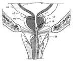
- FIG. 1Bshows a coronal section through the lower abdomen of a male human suffering from BPH showing a hypertrophied prostate gland treated with an embodiment of the device of the present invention.
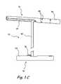
- FIG. 1Cshows a side view of an embodiment of the retractor shown in FIG. 1B .
- FIGS. 1D through 1Jshow the various steps of a method of treating a prostate gland by the retractor shown in FIG. 1C .
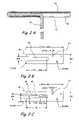
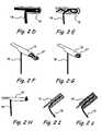
- FIG. 2Ashows a sectional view through the embodiment of a distal anchor shown in FIG. 1C .
- FIG. 2Bshows a first embodiment of a flat pattern that can be used to design the distal anchor of FIG. 2A .
- FIG. 2Cshows a second embodiment of a flat pattern that can be used to design the distal anchor of FIG. 2A .
- FIG. 2Dshows a longitudinal sectional view through an embodiment of a distal anchor that is attached to a connector by a crimped loop.
- FIG. 2Eshows a longitudinal sectional view through an embodiment of a distal anchor that is attached to a connector by multiple crimped loops.
- FIG. 2Fshows a perspective view through an embodiment of a distal anchor that is attached to a connector by a buckle.
- FIG. 2Gshows a side view of the embodiment of a distal anchor of FIG. 2F that is attached to a connector under tension.
- FIG. 2Hshows a perspective view of an embodiment of a distal anchor that is attached to a connector by a knot.
- FIG. 2Ishows a longitudinal sectional view through an embodiment of a distal anchor that is attached to a connector by an adhesive.
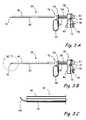
- FIG. 3Ashows a side view of a first embodiment of a distal anchor delivery device.
- FIG. 3Bshows the distal anchor delivery device of FIG. 3A with a portion of the distal region removed.
- FIG. 3Cshows an enlarged view of the distal region 3 C of FIG. 3B .
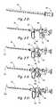
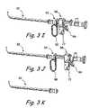
- FIGS. 3D through 3Kshow various steps of a method of deploying a distal anchor in the anatomy by the distal anchor delivery device of FIG. 3A .
- FIG. 3Lshows a side view of a second embodiment of a distal anchor delivery device.
- FIGS. 3M through 3Tshow steps of an embodiment of a method for deploying the anchor of FIG. 3L in an anatomical region.
- FIG. 3Ushows a first side view of the distal tip of an embodiment of a needle that can be used to introduce one or more of the distal anchors disclosed herein.
- FIG. 3Vshows a second side view of the distal tip of the embodiment of the needle shown in FIG. 3U .
- FIG. 3Wshows a longitudinal section through the distal tip of a distal anchor delivery device comprising a bushing to guide the trajectory of a needle through the distal anchor delivery device.
- FIG. 3Xshows a longitudinal section through the distal tip of a distal anchor delivery device comprising a distal crimp or dimple to guide the trajectory of a needle through the distal anchor delivery device.
- FIG. 3Yshows a perspective view of the distal tip of a distal anchor delivery device comprising a bent, curved or angled needle introducing lumen.
- FIG. 3Zshows a perspective view of an embodiment of a first elongate part that is used to construct the distal end of the embodiment of the distal anchor delivery device of FIG. 3Y .
- FIG. 3 A′shows a perspective view of an embodiment of a second elongate part that is used to construct the distal end of the embodiment of the distal anchor delivery device of FIG. 3Y .
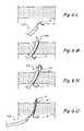
- FIGS. 4A and 4Bshow longitudinal sections through a first embodiment of a proximal anchor showing the steps of an embodiment of a method of attaching the proximal anchor to a connector.
- FIG. 4Cshows a first embodiment of a flat pattern that can be used to design the proximal anchor of FIG. 4A .
- FIGS. 4D and 4Eshow longitudinal sections through a second embodiment of a proximal anchor showing the steps of an embodiment of a method of attaching the proximal anchor to a connector.
- FIGS. 4F and 4Gshow longitudinal sections through a third embodiment of a proximal anchor showing the steps of an embodiment of a method of attaching the proximal anchor to a connector.
- FIG. 4Hshows an embodiment of a flat pattern that can be used to design the proximal anchor of FIGS. 4F and 4G .
- FIGS. 4I and 4Jshow longitudinal sections through a fourth embodiment of a proximal anchor showing the steps of an embodiment of a method of attaching the proximal anchor to a connector.
- FIGS. 4K and 4Lshow longitudinal sections through a proximal anchor showing the steps of an embodiment of a method of anchoring a connector to a proximal anchor by an elongate wedging device comprising multiple branches or bristles.
- FIGS. 4M and 4Nshow longitudinal sections through an embodiment of a proximal anchor showing the steps of an embodiment of a method of anchoring a connector to a proximal anchor by a lock pin pulled by a flexible pull shaft.
- FIGS. 4O and 4Pshow longitudinal sections through an embodiment of a proximal anchor showing the steps of an embodiment of a method of anchoring a connector to the proximal anchor by a hollow wedging element.
- FIGS. 4Q and 4Rshow an embodiment of a method of using a compression cutter for cutting the excess length of a connector and a wedging element.
- FIGS. 4S and 4Tshow longitudinal sections through a first embodiment of a proximal anchor comprising a crimping zone showing the steps of an embodiment of a method of anchoring a connector to the proximal anchor.
- FIGS. 4U and 4Vshow longitudinal sections through a second embodiment of a proximal anchor comprising a crimping zone showing the steps of an embodiment of a method of anchoring a connector to the proximal anchor.
- FIGS. 4W and 4Xshow a third embodiment of a proximal anchor comprising multiple crimping zones showing the steps of an embodiment of a method of anchoring a connector to the proximal anchor.
- FIG. 4Yshows a side view of an embodiment of a proximal anchor comprising a tapering outer surface.
- FIGS. 4 Z through 4 ABshow side views of the embodiment of the proximal anchor of FIG. 4Y showing the steps of an embodiment of a method of anchoring a connector to the proximal anchor by an anchoring ring.
- FIG. 4 ACshows a cross sectional view of an embodiment of the cutting ring of FIGS. 4 AA and 4 AB.
- FIG. 4 ADshows a side view of a first embodiment of a proximal anchor made of a thermal shape memory alloy.
- FIG. 4 AEshows a cross section of the proximal anchor of FIG. 4 AD through the line 4 AE- 4 AE when the shape memory material of the proximal anchor is in the martensite phase.
- FIG. 4 AE′shows a cross section of the proximal anchor of FIG. 4 AD through the line 4 AE- 4 AE when the shape memory material of the proximal anchor is in the programmed shape.
- FIG. 4 AFshows a cross section of the proximal anchor of FIG. 4 AD through the line 4 AF- 4 AF when the shape memory material of the proximal anchor is in the martensite phase.
- FIG. 4 AF′shows a cross section of the proximal anchor of FIG. 4 AD through the line 4 AF- 4 AF when the shape memory material of the proximal anchor is in the programmed shape.
- FIG. 4 AGshows a side view of a second embodiment of a proximal anchor made of a thermal shape memory alloy.
- FIG. 4 AHshows a cross section of the proximal anchor of FIG. 4 AG through the line 4 AH- 4 AH when the shape memory material of the proximal anchor is in the martensite phase.
- FIG. 4 AH′shows a cross section of the proximal anchor of FIG. 4 AG through the line 4 AH- 4 AH when the shape memory material of the proximal anchor is in the programmed shape.
- FIGS. 4 AI and 4 AJshow longitudinal sections of an embodiment of a proximal anchor showing the steps of an embodiment of a method of anchoring a looped or folded region of the connector to the proximal anchor.
- FIG. 4 AKshows a side view of an embodiment of a proximal anchor made of a suitable elastic or super elastic or shape memory material comprising one or more inwardly opening flaps.
- FIG. 4 ALshows a longitudinal section through the embodiment of the proximal anchor of FIG. 4 AK.
- FIG. 5Ashows a side view of a first embodiment of a proximal anchor delivery device comprising one or more finger activated triggers.
- FIGS. 5B through 5Dshow longitudinal sections through the distal tip of the proximal anchor delivery device of FIG. 5A showing the steps of a method of deploying a proximal anchor in the anatomy.
- FIG. 5Eshows a side view of a proximal anchor similar to the proximal anchor in FIGS. 5B-5D having a undeployed lock pin partially inserted into the proximal anchor.
- FIGS. 5F through 5Hshow longitudinal sections through the proximal anchor and the lock pin of FIG. 5E showing the steps of a method of attaching the proximal anchor to a connector using the lock pin.
- FIG. 5Ishows a side view of an embodiment of a lock pin that can be used to lock a connector to a proximal anchor as shown in the method of FIGS. 5B-5D .
- FIG. 5Jshows another side view of the lock pin of connector shown in FIG. 5I .
- FIG. 5Kshows an isometric view of an embodiment of an actuator that can be used to drive a lock pin into a proximal anchor.
- FIG. 5Lshows a side view of the embodiment of the actuator shown in FIG. 5K .
- FIG. 5Mshows a longitudinal section through the actuator of FIG. 5L .
- FIG. 5Nshows a side view of a second embodiment of a proximal anchor delivery device.
- FIGS. 5O through 5Sshow the steps of an embodiment of a method of deploying an anchor in an anatomical region using the proximal anchor delivery device of FIG. 5N .
- FIG. 5Tshows the distal end of an embodiment of a proximal anchor delivery device comprising an anchor tube with a bent, curved or angled distal end.
- FIG. 5Ushows the step of deploying a proximal anchor in an anatomical region by the proximal anchor delivery device of FIG. 5T .
- FIG. 5Vshows a cystoscopic view of a region of canine urethra enclosed by the prostate gland that has been treated by a procedure similar to the procedure shown in FIGS. 1D through 1J .
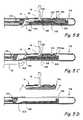
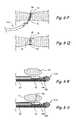
- FIG. 6Ashows a side view of an embodiment of a distal anchor delivery device.
- FIG. 6Bshows an enlarged view of the distal region of the distal anchor delivery device of FIG. 6A showing the step of deploying a distal anchor by the distal anchor delivery device.
- FIG. 6Cshows a side view of an embodiment of a proximal anchor delivery device.
- FIG. 6Dshows an enlarged view of the distal region of the proximal anchor delivery device of FIG. 6C .
- FIG. 6Eshows the distal region of an embodiment of a proximal anchor delivery device comprising a curved penetrating distal tip.
- FIG. 6Fshows an embodiment of a retractor comprising a proximal anchor buried within an anatomical tissue by the proximal anchor delivery device of FIG. 6E .
- FIG. 6Gshows the distal region of an embodiment of a proximal anchor delivery device comprising a straight penetrating distal tip.
- FIG. 6Hshows an embodiment of a retractor comprising a proximal anchor buried within an anatomical tissue by the proximal anchor delivery device of FIG. 6G .
- FIG. 6Ishows a section through the distal tip of a first embodiment of a combined device that can deliver a distal anchor connected to a proximal anchor by a connector.
- FIG. 6Jshows a side view of a second embodiment of a combined device that can deliver a distal anchor and a proximal anchor connected to each other by a connector.
- FIG. 6Kshows another view of the embodiment of the combined device shown in FIG. 6J that can deliver a distal anchor and a proximal anchor connected to each other by a connector.
- FIGS. 6L through 6Qshow the steps of a method of compressing an anatomical tissue by a combined device that delivers a proximal anchor and a distal anchor in the anatomy.
- FIGS. 6R through 6Wshow the distal region of an embodiment of a combined device showing the steps of a method of delivering a retractor comprising a proximal anchor and a distal anchor, wherein the distal anchor is delivered through the proximal anchor.
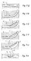
- FIGS. 7A through 7Hshow a longitudinal section of a tubular organ showing the steps of a method of reducing the cross sectional area of the lumen of the tubular organ.
- FIG. 7Ishows a schematic diagram of a tubular organ showing the configuration of the tubular organ before performing the method shown in FIGS. 7A through 7H .
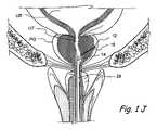
- FIG. 7Jshows a schematic diagram of the tubular organ of FIG. 7I showing a possible configuration obtained after performing the method shown in FIGS. 7A through 7H .
- FIG. 7Kshows an embodiment of a distal anchor delivery device comprising a helical needle.
- FIGS. 7L through 7Nshow a cross section of a tubular organ showing the steps of a method of reducing the cross sectional area of the lumen of the tubular organ by creating one or more folds or pleats in the walls of the tubular organ along the circumference of the lumen.
- FIG. 7Oshows a cross section of a tubular organ showing a first embodiment of a method of compressing a tissue adjacent to a tubular organ to cause one or more regions of the tissue to displace the walls of the tubular organ thereby reducing the cross sectional area of the lumen of the tubular organ.
- FIG. 7Pshows a cross section of a tubular organ showing a second embodiment of a method of compressing a tissue adjacent to a tubular organ to cause one or more regions of the tissue to displace the walls of the tubular organ thereby reducing the cross sectional area of the lumen of the tubular organ.
- FIGS. 7Q through 7Vshow longitudinal sections of a tubular organ showing the steps of a method of reducing the cross sectional area of the lumen of the tubular organ by creating one or more folds or bulges in the walls of the tubular organ along the axis of the tubular organ.
- FIGS. 7W through 7Yshows cross sections of a tubular organ showing the steps of a first embodiment of a method of reducing the cross sectional area of the lumen of the tubular organ by implanting a device that pinches the walls of the tubular organ to create a recess.
- FIGS. 7 Z through 7 ADshow cross sections of a tubular organ showing the steps of a second embodiment of a method of reducing the cross sectional area of the lumen of the tubular organ by implanting a device that pinches the walls of the tubular organ to create a recess.
- FIG. 7 AEshows a cross section of a tubular organ showing the steps of a first embodiment of a method of reducing the cross sectional area of the lumen of the tubular organ by implanting devices that pinch the walls of the tubular organ to create two recesses.
- FIG. 7 AFshows a cross section of a tubular organ showing a step of a second embodiment of a method of reducing the cross sectional area of the lumen of the tubular organ by implanting devices that pinch the walls of the tubular organ to create two recesses.
- FIG. 7 AGshows a cross section of a tubular organ showing a method of reducing the cross sectional area of the lumen of the tubular organ by creating a recess in the walls of the tubular organ and reinforcing the recessed region.
- FIG. 8Ashows an anchoring system implanted in a stomach to reduce the volume of the stomach to treat obesity.
- FIG. 8Bshows a cross sectional view of a stomach before implanting an anchoring system to reduce the volume of the stomach.
- FIG. 8Cshows a cross sectional view of the stomach of FIG. 8B after implanting an anchoring system to reduce the volume of the stomach.
- FIG. 8Dshows a section through wound edges closed by an anchoring system in a first configuration.
- FIG. 8Eshows a section through wound edges closed by an anchoring system in a second configuration.
- FIG. 8Fshows an anchoring device used to reconnect torn tissues of the musculoskeletal system.
- FIGS. 8Gshows a sagittal section through the head of a patient suffering from sleep apnea.
- FIGS. 8Hshows a sagittal section through the head of a patient suffering from sleep apnea who has been treated with two anchoring devices that displace the obstructing portions of the soft palate SP and the tongue To.
- FIG. 8Ishows an anchoring system that is implanted to lift loose skin in the face of a human.
- FIG. 8Jshows a view of a human face showing facial regions that may be treated by a method similar to the method shown in FIG. 8I to improve the cosmetic appearance of the human.
- FIG. 8Kshows a sagittal section through the lower abdomen of a human female showing an embodiment of a method of treating female urinary incontinence by a sling attached to the anatomy by anchoring devices.
- FIG. 8Lshows a cross section of a normal urethra UT.
- FIG. 8Mshows a cross section of the urethra UT in a human female suffering from stress urinary incontinence.
- FIG. 8Nshows a cross section of the urethra UT in a human female suffering from stress urinary incontinence where the urethra UT has been supported with a sling.
- FIG. 8Oshows a section through the lower abdomen of a human female suffering from stress urinary incontinence where the urethra UT has been supported with a sling.
- FIG. 8Pshows a section through the lower abdomen showing an embodiment of a colposuspension procedure wherein one or more regions of the vaginal wall of a patient suffering from incontinence are suspended to the Cooper's ligament by one or more anchoring devices.
- FIG. 8Qshows an anchoring device used to attach a seal to a puncture site on a blood vessel BV to seal the puncture site.
- FIG. 8Rshows a view of the pectoral region of a human female.
- FIG. 8Sshows the pectoral region of a human female wherein mastopexy has been performed on one or more regions of the breasts using the anchoring devices disclosed herein.
- FIG. 1Ashows a coronal section (i.e., a section cut approximately in the plane of the coronal suture or parallel to it) through the lower abdomen of a male human suffering from BPH showing a hypertrophied prostate gland.
- the urinary bladder UBis a hollow muscular organ that temporarily stores urine. It is situated behind the pubic bone PB.
- the lower region of the urinary bladderhas a narrow muscular opening called the bladder neck which opens into a soft, flexible, tubular organ called the urethra UT.
- the muscles around the bladder neckare called the internal urethral sphincter.
- the internal urethral sphincteris normally contracted to prevent urine leakage.
- the urinary bladdergradually fills with urine until full capacity is reached, at which point the sphincters relax. This causes the bladder neck to open, thereby releasing the urine stored in the urinary bladder into the urethra.
- the urethraconducts urine from the urinary bladder to the exterior of the body.
- the urethrabegins at the bladder neck and terminates at the end of the penis.
- the prostate gland PGis located around the urethra at the union of the urethra and the urinary bladder. In FIG. 1A , the prostate gland is hypertrophied (enlarged). This causes the prostate gland to press on a region of the urethra. This in turn creates an undesired obstruction to the flow of urine through the urethra.
- FIG. 1Bshows a coronal section through the lower abdomen of a male human suffering from BPH showing a hypertrophied prostate gland treated with an embodiment of the device of the present invention. It has been discovered that the enlarged prostate gland is compressible and can be retracted so as to relieve the pressure from the urethra.
- a retractor devicecan be placed through the prostate gland in order to relieve the pressure on the urethra.
- a retractor 10is implanted in the prostate gland.
- Retractor 10comprises a distal anchor 12 and a proximal anchor 14 .
- Distal anchor 12 and a proximal anchor 14are connected by a connector 16 .
- the radial distance from the urethra to distal anchor 12is greater than the radial distance from the urethra to proximal anchor 14 .
- the distance or tension between the anchorsis sufficient to compress, displace or change the orientation of an anatomical region between distal anchor 12 and proximal anchor 14 .
- the connector 16can be inelastic so as to maintain a constant force or distance between the proximal and distal anchors or be elastic so as to attempt to draw the proximal and distal anchors closer together.
- distal anchor 12is located on the outer surface of the capsule of prostate gland CP and acts as a capsular anchor.
- distal anchor 12may be embedded inside the tissue of prostate gland PG or in the surrounding structures around the prostate such as periosteum of the pelvic bones, within the bones themselves, pelvic fascia, coopers ligament, muscles traversing the pelvis or bladder wall.
- proximal anchor 14is located on the inner wall of urethra UT and acts as a urethral anchor.
- proximal anchor 14may be embedded inside the tissue of prostate gland PG or surrounding structures as outlined above.
- Distal anchor 12 and proximal anchor 14are implanted in the anatomy such that a desired distance or tension is created in connector 16 .
- FIG. 1BThis causes distal anchor 12 and proximal anchor 14 to retract or compress a region of prostate gland PG to relieve the obstruction shown in FIG. 1A .
- two retractors 10are implanted in prostate gland PG. Each retractor 10 is implanted in a lateral lobe (side lobe) of prostate gland PG.
- the various methods and devices disclosed hereinmay be used to treat a single lobe or multiple lobes of the prostate gland or other anatomical structures.
- two or more devices disclosed hereinmay be used to treat a single anatomical structure.
- a lateral lobe of prostate gland PGmay be treated using two retractors 10 .
- retractor 10is deployed between the 1 o'clock and 3 o'clock position relative to the axis of the urethra to target the left lateral lobe of the prostate gland. In another embodiment, retractor 10 is deployed between the 9 o'clock and 11 o'clock position relative to the axis of the urethra to target the right lateral lobe of the prostate gland. In another embodiment, retractor 10 is deployed between the 4 o'clock and 8 o'clock position relative to the axis of the urethra to target the middle lobe of the prostate gland.
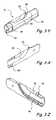
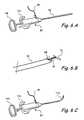
- FIG. 1Cshows a side view of one embodiment of the retractor shown in FIG. 1B .
- FIG. 1Cshows retractor 10 comprising distal anchor 12 and proximal anchor 14 .
- Distal anchor 12 and proximal anchor 14are connected by connector 16 .
- distal anchor 12comprises a tube 18 having a lumen.
- Tube 18can be made of suitable elastic or non-elastic materials including, but not limited to metals, polymers, etc.
- Typical examples of such materialsinclude, but are not limited to stainless steel 304, stainless steel 316, nickel-Titanium alloys, titanium, Pebax, Polyimide, braided Polyimide, Polyurethane, Nylon, PVC, Hytrel, HDPE, PEEK, PTFE, PFA, FEP, EPTFE, shape memory polymers, such as polyesterurethane, polyetherurethane, polyetherpolyesters, polyetherpolyamines or combinations of oligo e-caprolactore diol and oligo p-dioxanone diol polymers, etc.
- Connector 16is attached to tube 18 .
- connector 16is a USP size 0 polypropylene monofilament suture.
- a distal region of connector 16is located in the lumen of tube 18 such that the distal tip of connector 16 emerges out of one end of the lumen of tube 18 .
- the distal tip of connector 16is enlarged, such that the diameter of the enlarged distal tip of connector 16 is greater than the inner diameter of tube 18 .
- the diameter of connector 16is 0.014 inches and the diameter of the enlarged distal tip of connector 16 is 0.025 inches.
- the enlarged distal tip of connector 16is created by controlled melting of the distal tip of connector 16 . This attaches connector 16 to tube 18 .
- Tube 18may comprise one or more additional attachment mechanisms to attach a distal region of connector 16 to tube 18 .
- the distal region of connector 16is attached to tube 18 by a suitable biocompatible adhesive.
- the distal region of connector 16is attached to tube 18 by one or more inwardly opening flaps 20 that are cut in the material of tube 18 . Flaps 20 grip connector 16 and thus prevent the relative motion of connector 16 and tube 18 .
- the angle between one of flaps 20 and connector 16may range from 1 degree to 90 degrees.
- Tube 18further comprises a longitudinal slot 22 . Longitudinal slot 22 extends from one end to roughly the mid section of tube 18 . Connector 16 emerges out of this longitudinal slot 22 .
- distal anchor 12when connector 16 is pulled in the proximal direction, distal anchor 12 assumes a T-shape that helps to anchor distal anchor 12 to an anatomical structure.
- Distal anchor 12may comprise a sharp edge to help penetrate distal anchor 12 through the anatomy.
- distal anchor 12is constructed by laser cutting an electropolished nickel-titanium alloy (e.g., nitinol) tube made of 50.8% nickel-49.2% titanium.
- the outer diameter of tube 18is 0.026 inches
- the inner diameter of tube 18is 0.015 inches
- the length of tube 18is 0.315 inches
- the length of longitudinal slot 22is 0.170 inches.
- proximal anchor 14comprises a tube 24 comprising a lumen.
- Tube 24can be made of suitable elastic or non-elastic materials including, but not limited to metals, polymers, etc. Typical examples of such materials include, but are not limited to stainless steel 304, stainless steel 316, nickel-Titanium alloys, titanium, Pebax, Polyimide, braided Polyimide, Polyurethane, Nylon, PVC, Hytrel, HDPE, PEEK, PTFE, PFA, FEP, ePTFE, such as polyesterurethane, polyetherurethane, polyetherpolyesters, polyetherpolyamines or combinations of oligo e-caprolactone diol and oligo p-dioxanone diol polymers, etc.
- An outwardly opening flap 26is cut through the material of tube 24 . Flap 26 is folded on the outer surface of tube 18 as shown in FIG. 1C . This creates an opening to the lumen of tube 24 that is lined by the atraumatic edge of the folded flap 26 . Connector 16 enters tube 24 through this opening to the lumen of tube 24 .
- Proximal anchor 14further comprises an attachment mechanism to attach connector 16 to tube 24 .
- Connector 16can be made of suitable elastic or non-elastic materials including, but not limited to metals, polymers, etc.
- tube 24has a length of 0.236 inches and an outer diameter of 0.027 inches and an inner diameter of 0.020 inches. The length of opening to the lumen of tube 24 is approximately 0.055 inches.
- the attachment mechanismcomprises a lock pin that frictionally attaches connector 16 to tube 24 .
- the lock pin and tube 24are made of stainless steel 316L.
- tube 24is laser cut and then electropolished. Lock pin is constructed using EDM (electrical discharge machining) and then passivated.
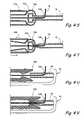
- FIGS. 1D through 1Jshow the various steps of a method of treating a prostate gland by the retractor shown in FIG. 1C . Similar methods may be also used to deploy retractor or compression devices in other anatomical structures.
- a sheath 28such as a standard resectoscope sheath is introduced into the urethra (trans-urethrally). Sheath 28 is advanced through urethra UT such that the distal end of sheath 28 is positioned near a region of urethra UT that is obstructed by a hypertrophied prostate gland PG.
- Distal anchor delivery device 30is introduced through sheath 28 .
- Distal anchor delivery device 30can be placed in the sheath 28 after the distal end of sheath 28 is positioned near the region of the urethra UT that is obstructed or the distal anchor delivery device 30 can be pre-loaded in the sheath 28 before positioning of the sheath 28 .
- Distal anchor delivery device 30is advanced through sheath 28 such that the distal end of distal anchor delivery device 30 emerges out of the distal end of sheath 28 .
- Distal anchor delivery device 30is oriented such that a working channel opening of distal anchor delivery device 30 points towards a lateral lobe of prostate gland PG.
- a needle 32is introduced through distal anchor delivery device 30 .
- Needle 32can be placed in distal anchor delivery device after the distal anchor delivery device 30 is advanced through sheath 28 or the needle 32 can be pre-loaded in the distal anchor delivery device 30 .
- needle 32is a 20 gauge needle. Needle 32 is advanced through distal anchor delivery device 30 such that it emerges through the working channel opening. Needle 32 is further advanced such that it penetrates through the tissue of prostate gland PG and the distal end of needle 32 emerges out of the capsule of prostate gland CP.
- distal anchor 12 connected to connector 16is advanced through needle 32 .
- Distal anchor 12can be pre-loaded in needle 32 or can be loaded in needle 32 after needle 32 has been advanced through distal anchor delivery device 30 .
- Distal anchor 12is advanced through needle 32 such that it emerges out of the distal end of needle 32 .
- needle 32is removed from distal anchor delivery device 30 by pulling needle 32 in the proximal direction.
- distal anchor delivery device 30is removed from sheath 28 by pulling distal anchor delivery device 30 in the proximal direction. Also, connector 16 is pulled to orient distal anchor 12 perpendicularly to connector 16 .
- connector 16is passed through proximal anchor 14 located on a proximal anchor delivery device 34 .
- Proximal anchor delivery device 34is advanced through sheath 28 such that the distal end of proximal anchor delivery device 34 emerges out of the distal end of sheath 28 .
- a desired tensionis introduced in connector 16 such that distal anchor 12 is pulled by connector 16 with a desired force.
- the proximal anchorcan be visualized through an endoscope or under fluoroscopy and advanced along the connector until the desired retraction of the tissue is achieved.
- connector 16is attached to proximal anchor 14 .
- Proximal anchor 14is also released from proximal anchor delivery device 34 , thus deploying proximal anchor 14 in the anatomy.
- Proximal anchor delivery device 34 and sheath 28are removed form the anatomy.
- Retractor 10comprising distal anchor 12 , proximal anchor 14 and connector 16 is used to retract, lift, support, reposition or compress a region of prostate gland PG located between distal anchor 12 and proximal anchor 14 . This method may be used to retract, lift, support, reposition or compress multiple regions or lobes of the prostate gland PG. In the method shown in FIGS.
- distal anchor 12is deployed on the outer surface of the capsule of prostate gland CP.
- distal anchor 12acts as a capsular anchor.
- distal anchor 12may be deployed inside the tissue of prostate gland PG or beyond the prostate as outlined previously.
- proximal anchor 14is deployed on the inner wall of urethra UT and acts as a urethral anchor.
- proximal anchor 14may be deployed inside the tissue of prostate gland PG.
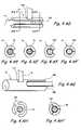
- FIG. 2Ashows a sectional view through the embodiment of a distal anchor shown in FIG. 1C .
- distal anchor 12comprises tube 18 comprising a lumen. Tube 18 is attached to a connector 16 .
- a distal region of connector 16is located in the lumen of tube 18 such that the distal tip of connector 16 emerges out of one end of the lumen of tube 18 .
- Distal anchor 12 and/or connector 16comprise one or more attachment mechanisms to attach distal anchor 12 to connector 16 .
- the attachment mechanismcomprises an enlarged distal tip of connector 16 .
- the enlarged distal tipis created by controlled melting of the distal tip of connector 16 .
- the attachment mechanismcomprises a suitable biocompatible adhesive that attaches the distal region of connector 16 to tube 18 .
- Other examples of attachment mechanismsinclude, but are not limited to one or more knots on connector 16 , one or more turnbuckles on connector 16 , crimped regions of distal anchor 12 , additional crimping elements that crimp onto the outer surface of connector 16 , or crimping elements that fit inside the tube, etc.
- Tube 18further comprises longitudinal slot 22 . Longitudinal slot extends from one end to roughly the mid section of tube 18 . Connector 16 emerges out of this longitudinal slot 22 .
- distal anchor 12when connector 16 is pulled in the proximal direction, distal anchor 12 assumes a T-shape that helps to anchor distal anchor 12 to an anatomical structure.
- Distal anchor 12may comprise a sharp edge to help penetrate distal anchor 12 through the anatomy.
- distal anchor 12comprises a nickel-titanium alloy (e.g., nitinol) tube and connector 16 comprises a polypropylene suture.
- a tubeis laser cut with a radially aligned laser.
- the geometry of the laser cut patternis specified using a flat pattern drawing which is mapped onto the outside circumference of the tube.
- FIG. 2Bshows a first embodiment of a flat pattern that can be used to manufacture a distal anchor 12 of FIG. 2A .
- flat pattern 36comprises a rectangular region.
- the length of the rectangular regionrepresents the length of the tube.
- the width of the rectangular region OCrepresents the outer circumference of the tube.
- the length of the rectangular regionis 0.315+/ ⁇ 0.005 inches and the width of the rectangular region is 0.088+/ ⁇ 0.001 inches.
- Flat pattern 36further comprises a U-shaped slot 38 cut at the proximal end of flat pattern 36 as shown in FIG. 2B .
- the width of slot 38is 0404+/ ⁇ 0.002 inches.
- the length of the straight region of slot 38is 0.174+/ ⁇ 0.005 inches.
- the distal end of slot 38comprises a semi-circular region as shown in FIG. 2B .
- the proximal end of slot 38comprises rounded edges with a radius of 0.2+/ ⁇ 0.005 inches.
- the distal region of flat pattern 36may comprise one or more semicircular notches 40 that create inwardly opening flaps 20 .
- flat pattern 36comprises three notches 40 .
- the width of notches 40is 0.010+/ ⁇ 0.001 inches.
- the length of the straight region of notches 40is 0.010+/ ⁇ 0.001 inches.
- the distal end of notches 40comprises a semi-circular region as shown in FIG. 2B .
- a suitable connector 16is passed through the lumen of the nickel-titanium alloy (e.g., nitinol) tube.
- Connector 16is attached to the distal end of the nickel-titanium alloy (e.g., nitinol) tube.
- Inwardly opening flaps 20are crimped onto the outer surface of connector 16 .
- This crimpingproduces additional anchoring sites on the nickel-titanium alloy (e.g., nitinol) tube to anchor connector 16 to the nickel-titanium alloy (e.g., nitinol) tube.
- the nickel-titanium alloy (e.g., nitinol) tubethen acts as distal anchor 12 .
- a region of connector 16emerges out of distal anchor through slot 38 .
- the diameter of slot 38may be designed to allow the edges of slot 38 to accurately contact the outer surface of connector 16 .
- FIG. 2Cshows a second embodiment of a flat pattern that can be used to design distal anchor 12 of FIG. 2A .
- flat pattern 42comprises a rectangular region. In one embodiment, the length of the rectangular region is 0.354+/ ⁇ 0.005 inches and the width of the rectangular region OC is 0.88+/ ⁇ 0.001 inches.
- Flat pattern 42further comprises a W-shaped slot 44 cut at the proximal end of flat pattern 42 as shown in FIG. 2C .
- the distal end of slot 44comprises two semi-circular regions as shown in FIG. 2C . In the embodiment shown in FIG. 2C , the radius of the semicircular regions is approximately 0.0015 inches.
- the length of slot 44 measured along the length of flat pattern 42 from the proximal end of flat pattern 42 to the proximal edges of the semicircular regionsis 0.174+/ ⁇ 0.005 inches.
- Slot 44encloses a central folding tab 46 .
- folding tab 46comprises a straight proximal region and a tapering distal region.
- the length of the straight proximal region of folding tab 46is 0.11+/ ⁇ 0.010 inches.
- the length of the tapering distal region of folding tab 46is 0.040+/ ⁇ 0.005 inches.
- the proximal end of slot 44has rounded edges with a radius of 0.020+/ ⁇ 0.005 inches.
- the distal region of flat pattern 42may comprise one or more semicircular notches 40 .
- flat pattern 42comprises three notches 40 that create inwardly opening flaps 20 .
- the width of notches 40is 0.010+/ ⁇ 0.001X inches.
- the length of the straight region of notches 40is 0.010+/ ⁇ 0.001 inches.
- the distal end of notches 40comprises a semi-circular region as shown in FIG. 2C .
- a suitable connector 16is passed through the lumen of the nickel-titanium alloy (e.g., nitinol) tube.
- Connector 16is attached to the distal end of the nickel-titanium alloy (e.g., nitinol) tube.
- Inwardly opening flaps 20are crimped onto the outer surface of connector 16 .
- This crimpingproduces additional anchoring sites on the nickel-titanium alloy (e.g., nitinol) tube to anchor connector 16 to the nickel-titanium alloy (e.g., nitinol) tube.
- the nickel-titanium alloy (e.g., nitinol) tubethen acts as distal anchor 12 .
- a region of connector 16emerges out of distal anchor through slot 44 .
- a blunt edgeis created at the distal edge of slot 44 .
- This blunt edgeis created by folding or bending folding tab 46 along the length of distal anchor 12 .
- Several alternate designs of the blunt edgemay be created using a variety of lengths of folding tab 46 and/or a variety of methods of folding or bending.
- distal anchor 12is attached to connector 16 by an attachment mechanism comprising an enlarged distal tip of connector 16 .
- attachment mechanismcomprising an enlarged distal tip of connector 16 .
- FIGS. 2D-2JSeveral alternate or complementary attachment mechanisms are illustrated in FIGS. 2D-2J .
- FIG. 2Dshows a longitudinal sectional view through an embodiment of a distal anchor that is attached to a connector by a crimped loop.
- the distal end of connector 16is looped. This looped distal end of connector 16 is inserted into distal anchor 12 .
- Distal anchor 12is crimped to attach the looped distal end of connector 16 to distal anchor 12 .
- FIG. 2Eshows a longitudinal sectional view through an embodiment of a distal anchor that is attached to a connector by multiple crimped loops.
- the distal end of connector 16is folded multiple times to obtain multiple loops. These multiple loops of connector 16 are inserted into distal anchor 12 .
- Distal anchor 12is crimped to attach the multiple loops of connector 16 to distal anchor 12 .
- FIG. 2Fshows a perspective view through an embodiment of a distal anchor that is attached to a connector by a buckle.
- the distal end of connector 16is passed through distal anchor 12 .
- the distal end of connector 16is passed through a buckle 47 and is looped.
- the distal end of connector 16is inserted back into distal anchor 12 .
- the distal end of connector 16may be attached to distal anchor 12 by one or more mechanisms disclosed herein.
- the distal end of connector 16is attached to distal anchor 12 by a suitable biocompatible adhesive.
- Distal anchor 12may be crimped to attach connector 16 to distal anchor 12 .
- FIG. 2Gshows a side view of the embodiment of a distal anchor of FIG. 2F that is attached to a connector under tension. Buckle 47 prevents the looped distal end of connector 16 from unraveling within distal anchor 12 .
- FIG. 2Hshows a perspective view of an embodiment of a distal anchor that is attached to a connector by a knot.
- the distal end of connector 16is passed through distal anchor 12 .
- the distal end of connector 16is knotted. This knot attaches the distal end of connector 16 to distal anchor 12 .
- FIG. 2Ishows a longitudinal sectional view through an embodiment of a distal anchor that is attached to a connector by an adhesive.
- the distal end of connector 16is passed through distal anchor 12 .
- This distal end of connector 16is attached to distal anchor 12 by a suitable biocompatible adhesive.
- biocompatible adhesivesthat can be used to attach connector 16 to proximal anchor 12 include, but are not limited to epoxies, cyanoacrylates and thermoplasitics.
- the inner surface of distal anchor 12may be roughened or may be provided with one or more projections or depressions to increase the strength of the attachment between connector 16 to proximal anchor 12 .
- the various distal anchors disclosed hereinmay be delivered by one or more distal anchor delivery devices.
- Such distal anchor delivery devicesmay be introduced in the body of a human or animal through a variety of access routes.
- the prostate gland of a patient with BPHmay be treated by a distal anchor delivery device introduced trans-urethrally.
- FIG. 3Ashows a side view of a first embodiment of a distal anchor delivery device 30 .
- Distal anchor delivery device 30comprises an elongate endoscope introducing tube 48 .
- the endoscope introducing tube 48may range in length from 8 inches to 13 inches.
- endoscope introducing tube 48is made of stainless steel.
- the proximal end of endoscope introducing tube 48may comprise an endoscope hub 50 to lock an endoscope to endoscope introducing tube 48 .
- the endoscopeis used to mean any telescope, camera or optical system that provides visualization.
- the endoscopeis a 4 mm endoscope.
- a region of endoscope introducing tube 48is attached to a distal handle assembly 52 .
- distal handle assembly 52is made of anodized aluminum, stainless steel and nickel-plated brass components. The components may be fastened to each other by soldering, braising, welding or stainless steel fasteners.
- distal handle assembly 52comprises a distal attachment 54 that encloses endoscope introducing tube 48 .
- Distal attachment 54is further attached to a distal handle 56 .
- a region of endoscope introducing tube 48 proximal to distal handle assembly 52passes through a proximal handle assembly 58 .
- proximal handle assembly 58is made of machined acetal resin engineering plastic (e.g., Delrin®, E.I.
- distal anchor delivery device 30further comprises one or more guide rails 60 .
- the distal ends of guide rails 60are attached to a proximal surface of distal attachment 54 .
- Guide rails 60pass through proximal handle assembly 58 such that proximal handle assembly 58 can slide over the outer surface of guide rails 60 .
- Distal anchor delivery device 30further comprises an elongate needle introducing tube 62 .
- Needle introducing tube 62is attached to endoscope introducing tube 48 as shown in FIG. 3A .
- needle introducing tube 62is made of stainless steel. Needle introducing tube 62 passes through distal handle assembly 52 and is attached to a region of distal handle assembly 52 .
- the distal tip of needle introducing tube 62may comprise a curved region.
- needle 32is made of nickel-titanium allow (e.g., nickel-titanium alloy (e.g., nitinol)) and comprises a ground beveled tip.
- the proximal end of needle 32is attached to proximal handle assembly 58 .
- Distal anchor delivery device 30may comprise a needle stop to control the maximum movement of proximal handle assembly 58 along endoscope introducing tube 48 .
- Needle 32comprises a lumen through which a distal anchor deploying system is introduced in the anatomy.
- the distal anchor deploying systemis used to deploy distal anchor 12 in the anatomy.
- the distal anchor deploying systemcomprises a pusher 64 that pushes distal anchor 12 out of needle 32 and into the anatomy.
- pusher 64is made of nickel-titanium alloy (e.g., nitinol).
- the proximal end of pusher 64is attached to a trigger 66 that is attached to a proximal handpiece 68 of the proximal handle assembly 58 .
- Trigger 66is attached to proximal handpiece 68 by a pivot 70 .
- Proximal handle assembly 58further comprises a safety system 72 that prevents unwanted motion of trigger 66 .
- safety system 72comprises a lock pin that locks trigger 66 to proximal handpiece 68 .
- the components of the safety systemare made of stainless steel.
- distal anchor delivery device 30is sized to be introduced through a 25F cystoscope sheath.
- the length of distal anchor delivery device 30 within the sheathranges from 6 to 10 inches.
- endoscope introducing tube 48 and endoscope hub 50are designed to fit a 4 mm telescope.
- the outer diameter of endoscope introducing tube 48ranges from 0.174 to 0.200 inches and the inner diameter of endoscope introducing tube 48 ranges from 0.160 to 0.180 inches.
- the outer diameter of needle introducing tube 62ranges from 0.059 to 0.83 inches and the inner diameter of needle introducing tube 62 ranges from 0.041 to 0.072 inches.
- the outer diameter of needle 32ranges from 0.034 to 0.043 inches and the inner diameter of needle 32 ranges from 0.027 to 0.035 inches.
- the outer diameter of pusher 64ranges from 0.020 to 0.026 inches and the inner diameter of pusher 64 ranges from 0.014 to 0.019 inches.
- the radius of the curved distal tip of needle introducing tube 62ranges from 0.25 to 0.50 inches.
- the maximum distance through which proximal handle assembly 58 can slide over the outer surface of endoscope introducing tube 48ranges from 1 to 2 inches. In this embodiment, the maximum distance through which pusher 64 travels relative to needle 32 ranges from 0.2 to 0.8 inches.
- distal anchor delivery device 30is sized to be introduced through a 25F cystoscope sheath.
- the length of distal anchor delivery device 30 within the sheathis 9.5 inches.
- endoscope introducing tube 48 and endoscope hub 50are designed to fit a 4 mm telescope.
- the outer diameter of endoscope introducing tube 48is 0.18 inches and the inner diameter of endoscope introducing tube 48 is 0.16 inches.
- the outer diameter of needle introducing tube 62is 0.083 inches and the inner diameter of needle introducing tube 62 is 0.072 inches.
- the outer diameter of needle 32is 0.037 inches and the inner diameter of needle 32 is 0.030 inches.
- the outer diameter of pusher 64is 0.025 inches and the inner diameter of pusher 64 is 0.020 inches.
- the radius of the curved distal tip of needle introducing tube 62is 0.3 inches.
- the maximum distance through which proximal handle assembly 58 can slide over the outer surface of endoscope introducing tube 48is 1.7 inches.
- the maximum distance through which pusher 64 travels relative to needle 32is 0.4 inches.
- FIG. 3Bshows the distal anchor delivery device of FIG. 3A with a portion of the distal region removed.
- FIG. 3Cshows an enlarged view of the distal region 3 C of FIG. 3B .
- FIG. 3Cshows the distal end of distal anchor delivery device 30 comprising elongate endoscope introducing tube 48 and needle introducing tube 62 .
- FIGS. 3D through 3Kshow various steps of a method of deploying distal anchor 12 in the anatomy by distal anchor delivery device 30 of FIG. 3A .
- the procedureis described as if applied to prostate gland although other anatomical regions could be used.
- an elongate sheath 28is introduced in the urethra.
- sheath 28is a 25F cystoscope resectoscope sheath. The position of sheath 28 is adjusted such that the distal tip of sheath 28 is close to the region of the urethra enclosed by the prostate gland.
- distal anchor delivery device 30is introduced through sheath 28 into the urethra.
- This stepmay be performed under endoscopic visualization by an endoscope 74 inserted in the endoscope introducing tube 48 of distal anchor delivery device 30 .
- Distal anchor delivery device 30may be rotated to orient the distal tip of needle introducing tube 62 in a desired orientation with respect to an anatomical organ such as the prostate gland.
- proximal handle assembly 58is moved in the distal direction over endoscope introducing tube 48 relative to distal handle assembly 52 . This in turn causes needle 32 to advance through needle introducing tube 62 . The distal tip of needle 32 emerges out of the distal tip of needle introducing tube 62 . Needle 32 penetrates through one or more anatomical regions.
- the distal tip of needle 32emerges out of the capsule of the prostate gland and enters the surrounding pelvic space.
- the dimensions of the prostate glandare measured. This information is then used to determine the distance through which needle 32 is advanced through needle introducing tube 62 .
- safety system 72is released. This step unlocks trigger 66 from proximal handpiece 68 .
- trigger 66is lifted. This causes pusher 64 to advance in the distal direction through needle 32 . This in turn causes distal anchor 12 to emerge out through the distal end of needle 32 and into the anatomy. In one method embodiment, distal anchor 12 emerges out of needle 32 and enters the surrounding pelvic space.
- FIG. 3Gsafety system 72 is released. This step unlocks trigger 66 from proximal handpiece 68 .
- trigger 66is lifted. This causes pusher 64 to advance in the distal direction through needle 32 . This in turn causes distal anchor 12 to emerge out through the distal end of needle 32 and into the anatomy. In one method embodiment, distal anchor 12 emerges out of needle 32
- connector 16is pulled in the proximal direction. This causes distal anchor 12 to orient itself perpendicularly to connector 16 .
- needle 32is removed from the anatomy by pulling proximal handle assembly 58 in the proximal direction over endoscope introducing tube 48 .
- distal anchor delivery device 30is removed from the anatomy.
- FIG. 3Lshows a side view of a second embodiment of a distal anchor delivery device 30 .
- Distal anchor delivery device 30comprises an endoscope introducing tube 48 .
- the proximal end of endoscope introducing tube 48may comprise an endoscope hub 50 to lock an endoscope 74 to endoscope introducing tube 48 .
- Endoscope introducing tube 48encloses a lumen through which endoscope 74 may be introduced into the anatomy.
- Distal anchor delivery device 30comprises a needle introducing tube 62 .
- Endoscope 74is introduced through endoscope introducing tube 48 such that the distal end of needle introducing tube 62 is located near the distal end of endoscope 74 .
- Needle introducing tube 62is used to introduce a needle 32 into the anatomy.
- the distal end of needle introducing tube 62may comprise a curved, bent or tapered region to introduce needle 32 into the anatomy at an angle to the axis of endoscope 74 .
- Needle introducing tube 62is attached to endoscope introducing tube 48 by a coupling element 76 .
- Distal anchor delivery device 30may be introduced into the anatomy through a suitable sheath.
- a suitable sheathmay comprise a flushing or aspiration port.
- the flushing or aspiration portmay be in fluid communication with the lumen of the sheath to allow a user to introduce fluids into or remove fluids from an anatomical region.
- FIGS. 3M through 3Tshow perspective views of distal anchor delivery device 30 of FIG. 3L showing the steps of an embodiment of a method of deploying an anchor in an anatomical region.
- Distal anchor delivery device 30comprises endoscope introducing tube 48 that encloses a lumen.
- An endoscope 74is located in the lumen of endoscope introducing tube 48 .
- distal anchor delivery device 30is introduced in an anatomical region such as the urethra through an elongate sheath 28 .
- Distal anchor delivery device 30may be rotated to orient the distal tip of needle introducing tube 62 in a desired orientation.
- a needle 32is introduced through needle introducing tube 62 .
- FIG. 3Mshow perspective views of distal anchor delivery device 30 of FIG. 3L showing the steps of an embodiment of a method of deploying an anchor in an anatomical region.
- Distal anchor delivery device 30comprises endoscope introducing tube 48 that encloses a lumen.
- needle 32is advanced through needle introducing tube 62 such that the distal end of needle 32 emerges out of the distal end of needle introducing tube 62 and enters an anatomical region.
- needle 32is advanced such that the distal end of needle 32 penetrates through the prostate gland and enters the surrounding pelvic space.
- the dimensions of the prostate glandmay be measured. This information may then be used to determine the distance through which distal end of needle 32 penetrates through the prostate gland.
- distal anchor 12 attached to connector 16is introduced into needle 32 .
- Distal anchor 12is pushed in the distal direction through needle 32 by pusher 64 .
- FIG. 3Nneedle 32 is advanced through needle introducing tube 62 such that the distal end of needle 32 emerges out of the distal end of needle introducing tube 62 and enters an anatomical region.
- needle 32is advanced such that the distal end of needle 32 penetrates through the prostate gland and enters the surrounding pelvic space.
- the dimensions of the prostate glandmay be measured. This information may then be used to determine the distance through
- distal anchor 12is further pushed in the distal direction through needle 32 by pusher 64 such that distal anchor 12 emerges out of the distal end of needle 32 .
- connector 16is pulled in the proximal direction. This causes distal anchor 12 to orient itself perpendicularly to connector 16 .
- needle 32 and pusher 64are pulled along the proximal direction. This step reintroduces the distal tip of needle 32 into needle introducing tube 62 .
- pusher 64 and needle 32are pulled further along the proximal direction such that pusher 64 and needle 32 are removed from distal anchor delivery device 30 .
- distal anchor delivery device 30is pulled along the proximal direction to remove distal anchor delivery device 30 from the anatomy.
- FIG. 3Ushows a first side view of the distal tip of an embodiment of a needle that can be used to introduce one or more of the distal anchors disclosed herein.
- FIG. 3Ushows a needle 32 comprising a sharp distal tip.
- Needle 32may be made of suitable biocompatible materials including, but not limited to nickel-titanium alloy (e.g., nitinol), stainless steel, etc. Needle 32 may comprise one or more curved, bent or angled regions.
- the outer diameter of needle 32may range from 0.034 inches to 0.043 inches. Needle 32 encloses a lumen such that the inner diameter of needle 32 ranges from 0.027 niches to 0.035 inches.
- the outer diameter of needle 32is approximately 0.0372 inches and the inner diameter is approximately 0.0295 inches.
- the length of needle 32may range from 10 to 15 inches. In a preferred embodiment, length of needle 32 is 13+/ ⁇ 0.2 inches.
- the distal tip of needle 32has a first bevel 78 and a second bevel 80 . In a preferred embodiment, the angle between first bevel 78 and the axis of needle 32 is 17 degrees. In this embodiment, the distance along the axis of needle 32 from the proximal end of first bevel 78 to the distal end of needle 32 is approximately 0.12 inches.
- Second bevel 80is curved as shown in FIG. 3U . In the embodiment shown in FIG. 3U , the distance along the axis of needle 32 from the proximal end of second bevel 80 to the distal end of needle 32 is approximately 0.07 inches.
- FIGS. 3Vshows a second side view of the distal tip of the embodiment of the needle shown in FIG. 3U .
- FIG. 3Vshows a side view of needle 32 showing first bevel 78 and second bevel 80 .
- the outer diameter of needle 32is 0.050 ⁇ 0.008 inches. Needle 32 encloses a lumen such that the inner diameter of needle 32 is 0.038+/ ⁇ 0.008 inches. The length of needle 32 is 12+/ ⁇ 4 inches. The angle between first bevel 78 and the axis of needle 32 may range from 20 to 24 degrees.
- the distal tip of distal anchor delivery device 30may comprise one or more guiding mechanisms to accurately guide the trajectory of needle 32 as needle 32 emerges from the distal tip of distal anchor delivery device 30 .
- Such guiding mechanismsmay also be used to prevent or reduce the scraping of the inner surface of distal anchor delivery device 30 by the sharp distal end of needle 32 .
- FIG. 3Wshows a longitudinal section through the distal tip of distal anchor delivery device 30 comprising a bushing 82 to guide the trajectory of needle 32 through distal anchor delivery device 30 .
- Bushing 82may be made of suitable biocompatible materials including, but not limited to biocompatible metals such as stainless steel, nickel-titanium alloy (e.g., nickel-titanium alloy (e.g., nitinol)), and/or polymers; etc.
- bushing 82is made of a curved cylindrical member.
- Bushing 82lines the inner surface of distal anchor delivery device 30 .
- bushing 82is attached to the inner surface of distal anchor delivery device 30 by a suitable adhesive.
- the distal end of bushing 82is located proximal to the distal tip of distal anchor delivery device 30 as shown. This enables the distal sharp tip of needle 32 to emerge from the distal tip of distal anchor delivery device 30 without substantially scraping the inner surface of distal anchor delivery device 30 .
- FIG. 3Xshows a longitudinal section through the distal tip of distal anchor delivery device 30 comprising a distal crimp 84 or dimple to guide the trajectory of needle 32 through distal anchor delivery device 30 .
- Distal crimp 84may be by crimping or dimpling the distal region of distal anchor delivery device 30 such that a region of distal crimp 84 extends into the lumen of distal anchor delivery device 30 .
- Distal crimp 84is located proximal to the distal tip of distal anchor delivery device 30 as shown.
- Distal crimp 84acts as a ramp for needle 32 .
- needle 32emerges from the distal tip of distal anchor delivery device 30 without substantially scraping the inner surface of distal anchor delivery device 30 .
- Distal anchor delivery device 30may comprise one or more distal crimps 84 or dimples.
- the distal tip of distal anchor delivery device 30may comprise a bent, curved or angled tip. Such a bent, curved, or angled tip may be designed to introduce one or more devices such as needle 32 into the anatomy at an angle to the axis of distal anchor delivery device 30 .
- the distal tip of distal anchor delivery device 30comprises one or more bent, curved or angled lumens.
- FIG. 3Yshows a perspective view of the distal tip of distal anchor delivery device 30 comprising a bent, curved or angled needle introducing lumen 86 . Needle introducing lumen 86 may be used to introduce a needle 32 or other devices into the anatomy. In the embodiment shown in FIG.
- needle introducing lumen 86comprises a straight proximal region and a bent, curved or angled distal region.
- the distal most region of needle introducing lumen 86may be oriented to the longitudinal axis of distal anchor delivery device 30 at an angle ranging from 30 degrees to 70 degrees.
- distal anchor delivery device 30further comprises a bent, curved or angled endoscope introducing lumen 88 .
- Endoscope introducing lumen 88may be used to introduce an endoscope 74 or other devices into the anatomy.
- endoscope introducing lumen 88comprises a straight proximal region and a bent, curved or angled distal region.
- the distal most region of endoscope introducing lumen 88may be oriented to the longitudinal axis of distal anchor delivery device 30 at an angle. Thus, both needle 32 and endoscope 74 may be introduced into the anatomy at desired angles through distal anchor delivery device 30 .
- needle introducing lumen 86may be made by drilling a lumen through the distal region of distal anchor delivery device 30 .
- needle introducing lumen 86is made of two grooved elongate parts that are attached to each other such that the two grooved elongate parts enclose needle introducing lumen 86 .
- the embodiment of the distal tip of distal anchor delivery device 30 shown in FIG. 3Yis made of two elongate parts: a first elongate part 90 and a second elongate part 92 .
- FIG. 3 Y′shows a perspective view of an embodiment of a first elongate part 90 that is used to construct the distal end of an embodiment of distal anchor delivery device 30 .
- First elongate part 90comprises a first groove 94 .
- First groove 94has a D-shaped cross section.
- the diameter of the semi-circular region of first groove 94is approximately 0.045+/ ⁇ 0.005 inches.
- First elongate part 90further comprises a second groove 96 .
- Second groove 96also has a D-shaped cross section.
- the diameter of the semi-circular region of second groove 96is approximately 0.172 ⁇ 0.010 inches.
- FIG. 3Zshows a perspective view of an embodiment of a second elongate part 92 that is used to construct the distal end of an embodiment of distal anchor delivery device 30 .
- Second elongate part 92comprises a third groove 98 .
- Third groove 98has a D-shaped cross section.
- First elongate part 90 and second elongate part 92are attached to each other such that second groove 96 and third groove 98 form endoscope introducing lumen 88 . Also, when first elongate part 90 and second elongate part 92 are attached to each other, first groove 94 and an outer surface of second elongate part 92 form a D-shaped needle introducing lumen 86 .
- FIGS. 4A and 4Bshow longitudinal sections through a first embodiment of a proximal anchor showing the steps of an embodiment of a method of attaching the proximal anchor to a connector.
- proximal anchor 14comprises a hollow tube.
- the hollow tubecomprises a connector opening 100 located roughly midway between the ends of the tube.
- connector opening 100is made by cutting outwardly opening flap 26 in the material of the tube. Outwardly opening flap 26 is folded as shown in FIG. 4A to create a blunt edge to connector opening 100 .
- Proximal anchor 14further comprises a locking tab 102 .
- Locking tab 102is made by cutting a flap in the material of proximal anchor 14 and bending the flap into the lumen of proximal anchor 14 as shown.
- Connector 16enters proximal anchor 14 through connector opening 100 .
- Connector 16emerges out of proximal anchor 14 through the distal end of proximal anchor 14 .
- Connector 16can be attached to proximal anchor 14 by a lock pin 104 .
- Lock pin 104comprises an elongate body with a tapering distal tip.
- Lock pin 104comprises a locking slot 106 .
- Locking slot 106is designed such that locking tab 102 fits into locking slot 106 . This temporarily locks lock pin 104 to proximal anchor 14 as shown in FIG. 4A .
- FIG. 4AIn FIG.
- lock pin 104is pushed in the distal direction by a user. This releases locking tab 102 from locking slot 106 . This in turn releases lock pin 104 from proximal anchor 14 . Lock pin 104 then moves in the distal direction. The tapering distal tip of lock pin 104 then wedges firmly between connector 16 and proximal anchor 14 . This attaches connector 16 to proximal anchor 14 . Lock pin 104 and proximal anchor 14 may comprise further mechanisms to prevent relative motion between lock pin and proximal anchor 14 after connector 16 is attached to proximal anchor 14 .
- edges of connector opening 100may be smoothened.
- the edgesare smoothened by applying a coating.
- the edgesare smoothened by polishing.
- the edgesare smoothened by folding the material around connector opening 100 .
- a tubeis laser cut with a radially aligned laser.
- the geometry of the laser cut patternis specified using a flat pattern drawing which is mapped onto the outside circumference of the tube.
- FIG. 4Cshows a first embodiment of a flat pattern that can be used to manufacture proximal anchor 14 of FIG. 4A .
- the length of the rectangular regionrepresents the length of the tube.
- the width of the rectangular region OCrepresents the outer circumference of the tube.
- third flat pattern 108comprises a rectangular region.
- the length of the rectangular regionis 0.236+/ ⁇ 0.005 inches and the width of the rectangular region OC is 0.088+/ ⁇ 0.002 inches.
- Third flat pattern 108further comprises a U-shaped slot 110 cut at the proximal end of third flat pattern 108 as shown in FIG. 4C .
- the largest width of slot 110is 0.028+/ ⁇ 0.001 inches.
- the total length of slot 110is 0.050+/ ⁇ 0.002 inches.
- the proximal end of slot 110encloses a rectangular region as shown in FIG. 4C .
- the rectangular regionis folded to create outwardly opening flap 26 .
- the distal end of slot 110comprises rounded edges with a radius of approximately 0.014 inches.
- the distal region of third flat pattern 108comprises a second U-shaped slot 112 as shown in FIG. 4C .
- a nickel-titanium alloye.g., nickel-titanium alloy (e.g., nitinol)
- stainless steel tubeis cut according to third flat pattern 108 .
- the rectangular region of slot 110is bent outwards to create outwardly opening flap 26 .
- the region enclosed by second U-shaped slot 112is bent inwards to create locking tab 102 .
- FIGS. 4D and 4Eshow longitudinal sections through a second embodiment of a proximal anchor showing the steps of an embodiment of a method of attaching the proximal anchor to a connector.
- proximal anchor 14comprises a hollow tube.
- the hollow tubecomprises a connector opening 100 located roughly midway between the ends of the tube.
- connector opening 100is made by cutting outwardly opening flap 26 in the material of the tube. Outwardly opening flap 26 is folded as shown in FIG. 4D to create a blunt edge to connector opening 100 .
- Connector 16enters proximal anchor 14 through connector opening 100 .
- Connector 16emerges out of proximal anchor 14 through a first shearing opening 114 of proximal anchor 14 .
- Connector 16can be attached to proximal anchor 14 by a lock pin 104 .
- Lock pin 104comprises an elongate body with a tapering proximal tip.
- Proximal anchor 14further comprises a securing mechanism to prevent lock pin 104 from separating from proximal anchor 14 .
- the securing mechanismcomprises a locking crimp 103 .
- Locking crimp 103is made by crimping a region of the wall of proximal anchor 14 .
- proximal anchorfurther comprises a second securing mechanism.
- the second securing mechanismcomprises a locking tab 102 .
- Locking tab 102fits into a locking slot 106 present on lock pin 104 .
- Lock pin 104further comprises a distal locking notch 118 that is located distal to locking slot 106 .
- Connector 16is attached to proximal anchor 14 by pulling an actuator 120 located on a proximal anchor delivery device 34 .
- Actuator 120comprises a distal bent region as shown in FIG.
- actuator 120pulls the distal end of lock pin 104 in the proximal direction.
- Actuator 120further comprises a second shearing opening 122 , such that connector 16 passes through second shearing opening 122 .
- Proximal anchoris prevented from moving in the proximal direction by a holder 124 located on a proximal anchor delivery device 34 .
- a userpulls actuator 120 in the proximal direction.
- Actuator 120in turn pulls lock pin 104 in the proximal direction.
- Lock pin 104then moves in the proximal direction.
- the tapering proximal tip of lock pin 104then wedges firmly between connector 16 and proximal anchor 14 .
- locking tab 102locks into distal locking notch 118 thereby further securing lock pin 104 to proximal anchor 14 .
- the movement of lock pin 104 in the proximal directionalso shears connector 16 between first shearing opening 114 and second shearing opening 122 . This cuts connector 16 thereby releasing proximal anchor 14 from proximal anchor delivery device 34 .
- Connector 16may enter or exit proximal anchor 14 through one or more connector openings.
- the walls of such openingsmay comprise one or more bent tabs.
- Such bent tabsmay be bent inwards into the proximal anchor and may be used to wedge lock pin 104 to connector 16 .
- FIGS. 4F and 4Gshow longitudinal sections through a third embodiment of a proximal anchor showing the steps of an embodiment of a method of attaching the proximal anchor to a connector.
- proximal anchor 14comprises a hollow tube.
- the hollow tubecomprises a connector opening 100 located roughly midway between the ends of the tube.
- connector opening 100is made by cutting an H-shaped slot in the material of the tube.
- the H-shaped slotcreates an outwardly opening flap 26 .
- Outwardly opening flap 26is folded as shown in FIG. 4F to create a blunt edge to connector opening 100 .
- the H-shaped slotalso creates an inwardly opening wedging tab 126 as shown in FIG. 4F .
- Proximal anchor 14further comprises a locking tab 102 .
- Locking tab 102is made by cutting a flap in the material of proximal anchor 14 and bending the flap into the lumen of proximal anchor 14 as shown.
- Connector 16enters proximal anchor 14 through connector opening 100 .
- Connector 16emerges out of proximal anchor 14 through an end of proximal anchor 14 .
- Connector 16can be attached to proximal anchor 14 by a lock pin 104 .
- Lock pin 104comprises an elongate body with a tapering tip.
- Lock pin 104comprises a locking slot 106 .
- Locking slot 106is designed such that locking tab 102 fits into locking slot 106 .
- FIG. 4Glock pin 104 is moved by a user. This releases locking tab 102 from locking slot 106 . This in turn releases lock pin 104 from proximal anchor 14 .
- Lock pin 104then moves within proximal anchor 14 such that the tapering tip of lock pin 104 wedges firmly between connector 16 and proximal anchor 14 . Further, wedging tab 126 gets wedged between lock pin 104 and connector 16 . This attaches connector 16 to proximal anchor 14 .
- Lock pin 104 and proximal anchor 14may comprise mechanisms to prevent relative motion between lock pin 104 and proximal anchor 14 after connector 16 is attached to proximal anchor 14 .
- a tubeis laser cut with a radially aligned laser.
- the geometry of the laser cut patternis specified using a flat pattern drawing which is mapped onto the outside circumference of the tube.
- FIG. 4Hshows an embodiment of a flat pattern that can be used to design proximal anchor 14 of FIGS. 4F and 4G .
- fourth flat pattern 128comprises a rectangular region. In one embodiment, the length of the rectangular region is 0.236 ⁇ 0.005 inches and the width of the rectangular region OC is 0.088+/ ⁇ 0.002 inches.
- the proximal region of fourth flat pattern 128comprises a U-shaped slot 112 as shown in FIG. 4H .
- Fourth flat pattern 128further comprises an H-shaped slot 130 as shown in FIG. 4H .
- the largest width of slot 110is 0.028+/ ⁇ 0.001 inches.
- the total length of slot 110is 0.050+/ ⁇ 0.002 inches.
- a nickel-titanium alloye.g., nickel-titanium alloy (e.g., nitinol)
- stainless steel tubeis cut according to fourth flat pattern 128 .
- the proximal rectangular region created by H-shaped slot 130is bent outwards to create outwardly opening flap 26 .
- the distal rectangular region created by H-shaped slot 130is bent inwards to create wedging tab 126 .
- the region created by U-shaped slot 112is bent inwards to create locking tab 102 .
- FIGS. 41 and 4Jshow longitudinal sections through a fourth embodiment of a proximal anchor showing the steps of an embodiment of a method of attaching the proximal anchor to a connector.
- Proximal anchor 14comprises a hollow tube. The tube comprises a proximal opening and a distal opening.
- Proximal anchor 14further comprises multiple connector openings 198 .
- Connector 16is introduced through one connector opening 100 and is weaved through the multiple connector openings 198 as shown in FIGS. 4I and 4J .
- the edges of connector openings 198may be coated or polished to facilitate smooth movement of proximal anchor 14 over connector 16 .
- Proximal anchor 14further comprises lock pin 104 located in the lumen of proximal anchor 14 .
- Proximal anchor 14may comprise one or more restricting elements to restrict the movement of lock pin 104 within proximal anchor 14 .
- proximal anchor 14comprises two crimps 132 that act as restricting elements. Crimps 132 prevent lock pin 104 from escaping from the lumen of proximal anchor 14 .
- proximal anchor 14is advanced over connector 16 to position proximal anchor 14 in a desired location.
- lock pin 104is advanced through proximal anchor 14 . Lock pin 104 wedges between connector 16 and proximal anchor 14 . This locks connector 16 to proximal anchor 14 . The excess length of connector 16 may be cut or trimmed.
- lock pin 104may be used to lock connector 16 to proximal anchor 14 .
- Such lock pins 104may comprise one or more tapered regions that wedge between connector 16 and a region of proximal anchor 14 .
- wedging elementsmay be used to attach connector 16 to a region of proximal anchor 14 .
- FIGS. 4K and 4Lshow longitudinal sections through a proximal anchor showing the steps of an embodiment of a method of anchoring a connector to a proximal anchor by an elongate wedging device comprising multiple branches or bristles.
- proximal anchor 14comprises a connector opening 100 through which a connector 16 passes.
- An elongate wedging element 134also passes through proximal anchor 14 such that one end of wedging element 134 can be pulled by a user.
- the embodiment of wedging element 134 shown in FIG. 4Kcomprises an elongate wedging shaft 136 .
- One or more branches or bristles 138are connected to wedging shaft 136 .
- wedging shaft 136 and bristles 138are made of suitable polymeric materials. Examples of such polymeric materials include, but are not limited to polyester, polyimide, PEEK, polyurethane, etc.
- one or more bristles 138are connected to each other to form a web.
- the movement of proximal anchor 14is restricted by a stopper 140 . In the step shown in FIG.
- proximal anchor 14is advanced over connector 16 to position proximal anchor 14 in a desired location.
- a userpulls wedging element 134 .
- Thiscauses a region of wedging element 134 comprising one or more bristles 138 to wedge between proximal anchor 14 and connector 16 .
- Thislocks connector 16 to proximal anchor 14 .
- the excess length of connector 16 and/or wedging element 134may be cut or trimmed.
- FIGS. 4M and 4Nshow longitudinal sections through an embodiment of a proximal anchor showing the steps of an embodiment of a method of anchoring a connector to a proximal anchor by a lock pin pulled by a flexible pull shaft.
- proximal anchor 14comprises a hollow elongate body comprising a connector opening 100 through which a connector 16 passes.
- Proximal anchor 14encloses an elongate lock pin 104 comprising a tapering proximal end. A user can pull lock pin 104 in the proximal direction by pulling an elongate flexible pull shaft 142 .
- Flexible pull shaft 142is detachably attached to lock pin 104 .
- the movement of proximal anchor 14is restricted by a stopper 140 .
- proximal anchor 14is advanced over connector 16 to position proximal anchor 14 in a desired location.
- flexible pull shaft 142is pulled in the proximal direction by a user. This pulls lock pin 104 in the proximal direction. Lock pin 104 wedges between connector 16 and proximal anchor 14 . This locks connector 16 to proximal anchor 14 .
- Flexible pull shaft 142is detached from lock pin 104 .
- the attachment between flexible pull shaft 142 and lock pin 104is designed to break at a pre-defined high force.
- flexible pull shaft 142is pulled in the proximal direction at the pre-defined high force. This detaches flexible pull shaft 142 from lock pin 104 .
- the attachment between flexible pull shaft 142 and lock pin 104is electrolytically detachable.
- an electric currentis passed through the attachment between flexible pull shaft 142 and lock pin 104 . This electrolytically dissolves the attachment between flexible pull shaft 142 and lock pin 104 . This in turn detaches flexible pull shaft 142 from lock pin 104 .
- FIGS. 4O and 4Pshow longitudinal sections through an embodiment of a proximal anchor showing the steps of an embodiment of a method of anchoring a connector to the proximal anchor by a hollow wedging element.
- proximal anchor 14comprises a hollow elongate body comprising a connector opening 100 through which a connector 16 passes.
- Proximal anchor 14encloses an elongate hollow wedging element 144 comprising a tapering distal end.
- Hollow wedging element 144is made of suitable high tensile strength materials such that hollow wedging element 144 can be pushed over connector 16 . Examples of such materials include, but are not limited to high stiffness polyimide, or PEEK, etc.
- proximal anchor 14is restricted by a stopper 140 .
- proximal anchor 14is advanced over connector 16 to position proximal anchor 14 in a desired location.
- Hollow wedging element 144is advanced over connector 16 while pulling connector 16 in the proximal direction. This causes hollow wedging element 144 to wedge between connector 16 and proximal anchor 14 as shown in FIG. 4P . This in turn attaches proximal anchor 14 to connector 16 .
- the lumen of hollow wedging element 144is lined with one or more barbs or projections.
- the one or more barbs or projectionsallow motion of connector 16 through the lumen of hollow wedging element 144 in one direction and prevent or substantially resist motion of connector 16 through the lumen of hollow wedging element 144 in the opposite direction.
- wedging element 144may be non-coaxial with connector 16 .
- wedging element 144may be pulled in a proximal direction in order to wedge wedging element 144 between connector 16 and proximal anchor 14 .
- FIGS. 4Q and 4Rshow an embodiment of a method of using a compression cutter for cutting the excess length of connector 16 and a wedging element.
- a connector 16is attached to proximal anchor 14 by hollow wedging element 144 . This may be done by the steps shown in FIGS. 4O-4P .
- a compression cutter 146is advanced over hollow wedging element 144 .
- Compression cutter 146comprises two or more distal cutting edges. The outer surface of the distal cutting edges comprises an enlarged region as shown in FIG. 4Q . The enlarged region increases the radial profile of compression cutter 146 near the distal cutting edges.
- a compressing shaft 148is advanced over compression cutter 146 .
- compressing shaft 148is advanced over the distal end of compression cutter 146 . This exerts a radially inward force on the distal cutting edges. This in turn compresses the distal cutting edges causing them to cut the region of connector 16 and hollow wedging element 144 enclosed by the distal cutting edges. Thus excess lengths of connector 16 and hollow wedging element 144 are removed from proximal anchor 14 .
- FIGS. 4S and 4Tshow longitudinal sections through a first embodiment of a proximal anchor comprising a crimping zone showing the steps of an embodiment of a method of anchoring a connector to the proximal anchor.
- proximal anchor 14comprises a hollow elongate body comprising a connector opening 100 .
- a connector 16enters proximal anchor 14 through connector opening 100 .
- Connector 16exits proximal anchor 14 through one end of proximal anchor 14 .
- the proximal end of proximal anchor 14comprises a crimping zone 150 . Crimping zone 150 can be crimped by a suitable radial compressive force.
- Crimping zone 150is enclosed by an elongate crimping device 152 as shown in FIG. 4S .
- the distal end of crimping device 152may be used to maintain the position of proximal anchor 14 .
- the distal end of crimping device 152is compressed by a compressing shaft 148 .
- proximal anchor 14is advanced over connector 16 to position proximal anchor 14 in a desired location.
- compressing shaft 148is advanced over crimping device 152 in the distal direction till compression shaft 148 passes over the enlarged distal end of crimping device 152 .
- Crimping device 152exerts a compressive force on crimping zone 150 . This force compresses crimping zone 150 causing it to crimp over connector 16 . This in turn causes proximal anchor 14 to attach to connector 16 .
- the excess length of connector 16may be cut or trimmed using a variety of cutting or trimming mechanisms.
- FIGS. 4U and 4Vshow longitudinal sections through a second embodiment of a proximal anchor comprising a crimping zone showing the steps of an embodiment of a method of anchoring a connector to the proximal anchor.
- Proximal anchor 14comprises a hollow elongate body comprising a connector opening 100 .
- a connector 16enters proximal anchor 14 through connector opening 100 .
- Connector 16exits proximal anchor 14 through one end of proximal anchor 14 .
- the proximal end of proximal anchor 14can be crimped by a suitable radial compressive force.
- the proximal end of proximal anchor 14is enclosed by an elongate crimping shaft 154 as shown in FIG. 4U .
- Crimping shaft 154encloses a lumen.
- the distal end of the lumen of crimping shaft 154is tapered as shown in FIG. 4U , such that the diameter of the lumen gradually decreases till a certain distance along the proximal direction.
- Connector 16passes through the lumen of crimping shaft 154 as shown in FIG. 4U .
- the distal end of crimping shaft 154 and a region of proximal anchor delivery device 34may be used to maintain the position of proximal anchor 14 .
- proximal anchor 14is advanced over connector 16 to position proximal anchor 14 in a desired location.
- FIG. 4Uproximal anchor 14 is advanced over connector 16 to position proximal anchor 14 in a desired location.
- crimping shaft 154is advanced in the distal direction.
- the proximal end of proximal anchor 14is forced into the lumen of crimping shaft 154 .
- the tapering lumen of crimping shaft 154exerts a radially compressive force on the proximal end of proximal anchor 14 .
- This forcecompresses the proximal end of proximal anchor 14 causing it to crimp over connector 16 .
- the excess length of connector 16may be cut or trimmed using a variety of cutting or trimming mechanisms.
- Compression shaft 148 and crimping shaft 154may be connected to a trigger mechanism to allow a user to controllably move compression shaft 148 and crimping shaft 154 .
- FIGS. 4W and 4Xshow a third embodiment of a proximal anchor comprising multiple crimping zones showing the steps of an embodiment of a method of anchoring a connector to the proximal anchor.
- proximal anchor 14comprises a hollow elongate body comprising a connector opening.
- a connector 16enters proximal anchor 14 through the connector opening.
- Connector 16exits proximal anchor 14 through one end of proximal anchor 14 .
- Proximal anchor 14comprises multiple crimping zones 150 . Crimping zones 150 can be crimped by a suitable radial compressive force.
- proximal anchor 14comprises three crimping zones 150 .
- the crimping zones 150are created in the material of proximal anchor 14 by creating U-shaped laser cuts. Each U-shaped cut encloses a flap that acts as a crimping zone 150 . In the embodiment shown in FIG. 4W , the U-shaped laser cuts are aligned circumferentially. In an alternate embodiment, the U-shaped laser cuts are aligned along the axis of proximal anchor 14 .
- the region of proximal anchor 14 comprising crimping zones 150is enclosed by an elongate crimping device 152 as shown in FIG. 4W .
- the lumen of crimping device 152may comprise one or more projections that coincide with crimping zones 150 .
- the distal end of crimping device 152comprises a tapering region as shown in FIG. 4W such that the outer diameter of crimping device 152 increases along the distal direction.
- the distal end of crimping device 152is compressed by a compressing shaft 148 .
- proximal anchor 14is advanced over connector 16 to position proximal anchor 14 in a desired location.
- compressing shaft 148is advanced over crimping device 152 in the distal direction till compression shaft 148 passes over the tapering distal end of crimping device 152 . This exerts a radially compressive force on the distal end of crimping device 152 .
- Crimping device 152in turn exerts a compressive force on crimping zones 150 . This force compresses crimping zones 150 causing them to crimp over connector 16 . This in turn causes proximal anchor 14 to attach to connector 16 . The excess length of connector 16 may be cut or trimmed using a variety of cutting or trimming mechanisms.
- FIG. 4Yshows a side view of an embodiment of a proximal anchor comprising a tapering outer surface.
- proximal anchor 14comprises an elongate tapering body with effective diameter “d” at one end smaller than effective diameter “D” at the other end.
- Proximal anchor 14further comprises an external groove or slot 156 on the outer surface of the elongate tapering body.
- suitable biocompatible materialsthat may be used to construct proximal anchor 14 include, but are not limited to metals e.g. nickel-titanium alloy (e.g., nickel-titanium alloy (e.g., nitinol)), stainless steel, titanium, polymers (e.g. polyester, polyimide, PEEK, polyurethane, etc.
- FIGS. 4 Z through 4 ABshow side views of the embodiment of the proximal anchor of FIG. 4Y showing the steps of an embodiment of a method of anchoring a connector to the proximal anchor by an anchoring ring.
- proximal anchor 14is positioned at a desired location in the anatomy along a connector 16 such that a portion of connector 16 passes through slot 156 .
- An anchoring ring 158is advanced over proximal anchor 14 .
- suitable biocompatible materialsthat may be used to construct anchoring ring 158 include, but are not limited to metals e.g. nickel-titanium alloy (e.g., nitinol), stainless steel, titanium, etc.; polymers e.g.
- Anchoring ring 158is advanced over proximal anchor 14 by a suitable pushing device.
- the pushing deviceis a hollow, elongate pushing rod.
- the diameter of the region of proximal anchor 14 enclosed by anchoring ring 158increases.
- anchoring ring 158firmly grips the outer surface of proximal anchor 14 . This causes a region of connector 16 to be compressed between a region of anchoring ring 158 and a region of proximal anchor 14 .
- a cutting ring 160is advanced over proximal anchor 14 as shown in FIG. 4 AA.
- suitable biocompatible materialsthat may be used to construct cutting ring 160 include, but are not limited to metals e.g. nickel-titanium alloy (e.g., nitinol), stainless steel, titanium, etc.; polymers e.g. polyester, polyimide, PEEK, polyurethane, etc.
- Cutting ring 160comprises a circular body that is attached to a cutting blade 162 .
- cutting ring 160As cutting ring 160 is advanced over proximal anchor 14 , the diameter of the region of proximal anchor 14 enclosed by cutting ring 160 increases. After cutting ring 160 is advanced to a certain distance along proximal anchor 14 , cutting blade 162 comes into contact with a region of connector 16 . Cutting ring 160 is advanced further to cut connector 16 by cutting blade 162 as shown in FIG. 4 AB.
- FIG. 4 ACshows a cross sectional view of an embodiment of the cutting ring of FIGS. 4 AA and 4 AB.
- cutting ring 160comprises a circular body that is attached to a cutting blade 162 that projects radially inwards.
- FIG. 4 ADshows a side view of a first embodiment of a proximal anchor made of a thermal shape memory alloy.
- proximal anchor 14comprises a hollow elongate body made of a suitable shape memory material.
- shape memory materialsinclude, but are not limited to nickel-titanium alloys (nickel-titanium alloy (e.g., nitinol)), copper-aluminum-nickel alloys, copper-zinc-aluminum alloys, iron-manganese-silicon alloys, etc.
- nickel-titanium alloynickel-titanium alloy (e.g., nitinol)
- copper-aluminum-nickel alloyscopper-zinc-aluminum alloys
- iron-manganese-silicon alloysetc.
- proximal anchor 14is made of nickel-titanium alloy (e.g., nitinol).
- Proximal anchor 14encloses a lumen. One end of proximal anchor 14 may be plugged by a lumen plug 164 . In the embodiment shown in FIG. 4 AD, proximal anchor 14 also comprises a longitudinal slit. The longitudinal slit creates a fluid communication between the lumen of proximal anchor 14 and the exterior of proximal anchor 14 . Proximal anchor 14 comprises a connector opening 100 . A connector 16 enters proximal anchor 14 through connector opening 100 . Connector 16 exits proximal anchor 14 through one end of proximal anchor 14 . A user can control the diameter of the lumen of proximal anchor 14 by changing the temperature of proximal anchor 14 .
- proximal anchor 14is introduced in the anatomy in the martensite phase of the shape memory material of proximal anchor 14 .
- the diameter of the lumen of proximal anchor 14 in the martensite stateis sufficiently large to allow proximal anchor 14 to be advanced over connector 16 .
- the martensite phasemay be achieved for example, by cooling proximal anchor 14 and introducing the cooled proximal anchor 14 in the anatomy. After proximal anchor 14 warms up to the body temperature, the shape memory material recovers a programmed shape and becomes super-elastic.
- the diameter of the lumen of proximal anchor 14is sufficiently small to allow proximal anchor 14 to attach to connector 16 .
- the excess length of connector 16may be cut or trimmed using a variety of cutting or trimming mechanisms.
- the temperature of proximal anchor 14is maintained or changed by controlling the temperature of a liquid such as saline that is brought into contact with proximal anchor 14 by a user.
- the lumen of proximal anchor 14is lined with one or more barbs or projections. The one or more barbs or projections allow motion of connector 16 through the lumen of proximal anchor 14 in one direction and prevent or substantially resist motion of connector 16 through the lumen of proximal anchor 14 in the opposite direction.
- FIG. 4 AEshows a cross section of the proximal anchor of FIG. 4 AD through the line 4 AE- 4 AE when the shape memory material of the proximal anchor is in the martensite phase.
- the diameter of the lumen of proximal anchor 14is larger than the outer diameter of proximal anchor 14 . This allows a user to advance proximal anchor 14 over connector 16 .
- FIG. 4 AE′shows a cross section of the proximal anchor of FIG. 4 AD through the line 4 AE- 4 AE when the shape memory material of the proximal anchor is in the programmed shape.
- the diameter of the lumen of proximal anchor 14is smaller than the outer diameter of proximal anchor 14 . This causes a region of proximal anchor 14 to compress a region of connector 16 . This in turn causes proximal anchor 14 to attach to connector 16 .
- FIG. 4 AFshows a cross section of the proximal anchor of FIG. 4 AD through the line 4 AF- 4 AF when the shape memory material of the proximal anchor is in the martensite phase.
- the diameter of the lumen of proximal anchor 14is larger than the outer diameter of lumen plug 164 .
- FIG. 4 AF′shows a cross section of the proximal anchor of FIG. 4 AD through the line 4 AF- 4 AF when the shape memory material of the proximal anchor is in the programmed shape.
- the diameter of the lumen of proximal anchor 14is smaller than the outer diameter of lumen plug 164 . This causes lumen plug 164 to substantially plug one end of the lumen of proximal anchor 14 .
- FIG. 4 AGshows a side view of a second embodiment of a proximal anchor made of a thermal shape memory alloy.
- proximal anchor 14comprises a hollow elongate body made of a suitable shape memory material.
- suitable shape memory materialsinclude, but are not limited to nickel-titanium alloys (nickel-titanium alloy (e.g., nitinol)), copper-aluminum-nickel alloys, copper-zinc-aluminum alloys, iron-manganese-silicon alloys, etc.
- nickel-titanium alloye.g., nickel-titanium alloy (e.g., nitinol)
- copper-aluminum-nickel alloyscopper-zinc-aluminum alloys
- iron-manganese-silicon alloysetc.
- proximal anchor 14is made of nickel-titanium alloy (e.g., nitinol).
- Proximal anchor 14encloses a lumen. One end of proximal anchor 14 may be plugged.
- proximal anchor 14comprises two or more shape memory arms 166 .
- Proximal anchor 14comprises a connector opening 100 .
- a connector 16enters proximal anchor 14 through connector opening 100 .
- Connector 16exits proximal anchor 14 through the region enclosed by shape memory arms 166 .
- a usercan control the size of the region enclosed by shape memory arms 166 by changing the temperature of proximal anchor 14 .
- proximal anchor 14is introduced in the anatomy in the martensite phase of the shape memory material of shape memory arms 166 .
- the size of the region enclosed by shape memory arms 166 in the martensite stateis sufficiently large to allow proximal anchor 14 to be advanced over connector 16 .
- the martensite phasemay be achieved for example, by cooling proximal anchor 14 and introducing the cooled proximal anchor 14 in the anatomy. After proximal anchor 14 warms up to the body temperature, the shape memory material recovers a programmed shape and becomes super-elastic. In the programmed shape, the size of the region enclosed by shape memory arms 166 is sufficiently small to cause shape memory arms 166 to compress a region of connector 16 . This causes proximal anchor 14 to attach to connector 16 . The excess length of connector 16 may be cut or trimmed using a variety of cutting or trimming mechanisms.
- the temperature of proximal anchor 14is maintained or changed by controlling the temperature of a liquid such as saline that is brought into contact with proximal anchor 14 by a user.
- the lumen of proximal anchor 14is lined with one or more barbs or projections. The one or more barbs or projections allow motion of connector 16 through the lumen of proximal anchor 14 in one direction and prevent or substantially resist motion of connector 16 through the lumen of proximal anchor 14 in the opposite direction.
- FIG. 4 AHshows a cross section of the proximal anchor of FIG. 4 AG through the line 4 AH- 4 AH when the shape memory material of the proximal anchor is in the martensite phase.
- the size of the region enclosed by shape memory arms 166is larger than the outer diameter of proximal anchor 14 . This allows a user to advance proximal anchor 14 over connector 16 .
- FIG. 4 AH′shows a cross section of the proximal anchor of FIG. 4 AG through the line 4 AH- 4 AH when the shape memory material of the proximal anchor is in the programmed shape.
- the size of the region enclosed by shape memory arms 166is smaller than the outer diameter of proximal anchor 14 . This causes the region enclosed by shape memory arms 166 to compress a region of connector 16 . This in turn causes proximal anchor 14 to attach to connector 16 .
- FIGS. 4 AI and 4 AJshow longitudinal sections of an embodiment of a proximal anchor showing the steps of an embodiment of a method of anchoring a looped or folded region of the connector to the proximal anchor.
- Proximal anchor 14comprises a hollow elongate body.
- a pull wire 168passes through the hollow proximal anchor 14 .
- Pull wire 168loops around connector 16 and reenters proximal anchor 14 as shown in FIG. 4 AI.
- the loop of pull wire 168pulls connector 16 towards proximal anchor 14 .
- the loop of pull wire 168is advanced over connector 16 . This causes proximal anchor 14 to be advanced over connector 16 .
- Proximal anchor 14is advanced to position proximal anchor 14 in a desired location.
- pull wire 168is pulled by a user. This pulls a loop of connector 16 inside proximal anchor 14 .
- the loop of connector 16 pulled inside proximal anchor 14wedges inside the lumen of proximal anchor 14 . This in turn causes connector 16 to attach to proximal anchor 14 .
- the excess length of connector 16 and/or pull wire 168may be cut or trimmed using a variety of cutting or trimming mechanisms.
- FIG. 4 AKshows a side view of an embodiment of a proximal anchor made of a suitable elastic or super elastic or shape memory material comprising one or more inwardly opening flaps.
- proximal anchor 14comprises a hollow tubular body.
- the hollow tubular bodyis made of a suitable elastic or super elastic or shape memory material. Examples of such materials include, but are not limited to metals such as nickel-titanium alloy (e.g., nitinol), stainless steel, titanium, etc. and polymers such as shape memory polymers, etc.
- the tubular bodycomprises one or more inwardly opening flaps 20 . In the embodiment shown in FIG.
- inwardly opening flaps 20are oriented along the axis of proximal anchor 14 .
- Inwardly opening flaps 20allow the motion of a connector 16 that passes through proximal anchor 14 along the direction of orientation of inwardly opening flaps 20 .
- inwardly opening flaps 20prevent the motion of connector 16 that passes through proximal anchor 14 along the direction opposite to the direction of orientation of inwardly opening flaps 20 . This enables proximal anchor 14 to be advanced over connector 16 along one direction.
- proximal anchor 14is made of an elastic or super elastic material. In this embodiment, proximal anchor 14 is introduced in the anatomy by sliding proximal anchor 14 over connector 16 in the direction of orientation of inwardly opening flaps 106 .
- Proximal anchor 14is advanced over connector 16 till proximal anchor 14 is located in a desired location. Inwarldy opening flaps 106 prevent the motion of proximal anchor 106 connector 16 in the direction opposite to the direction of orientation of inwardly opening flaps 106 .
- proximal anchor 14is made of a shape memory material such as nickel-titanium alloy (e.g., nitinol).
- nickel-titanium alloye.g., nitinol
- proximal anchor 14is introduced in the anatomy in the martensite phase of nickel-titanium alloy (e.g., nitinol). In this state, inwardly opening flaps 20 are aligned substantially parallel to the surface of proximal anchor 14 .
- proximal anchor 14to be advanced over connector 16 .
- the martensite phasemay be achieved, for example, by cooling proximal anchor 14 and introducing the cooled proximal anchor 14 in the anatomy.
- the nickel-titanium alloye.g., nitinol
- the nickel-titanium alloyrecovers a programmed shape and becomes super-elastic.
- inwardly opening flaps 20are bent inwards into the lumen of proximal anchor 14 . This attaches proximal anchor 14 to connector 16 .
- FIG. 4 ALshows a longitudinal section through the embodiment of the proximal anchor of FIG. 4 AK.
- Proximal anchor 14comprises a hollow tubular body comprising one or more inwardly opening flaps 20 .
- Inwardly opening flaps 20prevent the motion of connector 16 along the direction opposite to the direction of orientation of inwardly opening flaps 20 .
- proximal anchor 14is attached to connector 16 using a biocompatible adhesive.
- the biocompatible adhesivemay be introduced by a suitable proximal anchor delivery device 34 that comprises an adhesive injecting tube.
- proximal anchor 14is positioned at a desired location relative to connector 16 .
- a suitable biocompatible adhesiveis introduced such that the adhesive attaches proximal anchor 14 to a location on connector 16 .
- the adhesiveis introduced through a lumen in actuator 120 .
- FIG. 5Ashows a side view of a first embodiment of a proximal anchor delivery device comprising one or more finger activated triggers.
- the embodiment of proximal anchor delivery device 34 shown in FIG. 5Acomprises an elongate endoscope channel 170 .
- Elongate endoscope channel 170may be made of suitable biocompatible materials. Examples of such materials include, but not limited to polymers e.g. polyester, polyimide, PEEK, polyurethane, polysulfone, polyetherimides, polycarbonate, and may be filled with glass or reinforcing fiber, etc; metals e.g. stainless steel, titanium, etc.
- endoscope channel 170is made of 316 stainless steel.
- the proximal end of endoscope channel 170comprises an endoscope adapter hub 172 .
- Endoscope adapter hub 172allows a user to introduce an endoscope through the proximal end of endoscope channel 170 .
- the proximal region of endoscope channel 170is attached to a handle 174 .
- Proximal anchor delivery device 34further comprises an elongate anchor tube 176 .
- Anchor tube 176may be made of suitable biocompatible materials. Examples of such materials include, but not limited to polymers e.g. polyester, polyimide, PEEK, polyurethane, polysulfone, polyetherimides, polycarbonate, and may be filled with glass or reinforcing fiber, etc. metals e.g.
- anchor tube 176is made of 316 stainless steel.
- the distal end of anchor tube 176may comprise a blunt or atraumatic tip.
- Anchor tube 176is attached to endoscope channel 170 such that anchor tube 176 is substantially parallel to endoscope channel 170 as shown in FIG. 5A .
- Anchor tube 176comprises a lumen that encloses proximal anchor 14 .
- Proximal anchor 14is deployed in the anatomy through the distal region of anchor tube 176 .
- the distal region of anchor tube 176may comprise a bent, curved or angled region.
- Proximal anchor delivery device 34is used to attach a proximal anchor 14 to a desired location on a connector 16 .
- a suitable tensionmay be introduced into connector 16 before the step of attaching proximal anchor 14 to connector 16 .
- proximal anchor delivery device 34further comprises a tensioning mechanism.
- the tensioning mechanismcomprises a pulling mechanism. The pulling mechanism pulls connector 16 between a sliding rack 178 and a suture trap 180 .
- Suture trap 180is hinged to sliding rack 178 as shown in FIG. 5A . Sliding rack 178 moves on a sliding slot 182 located on handle 174 .
- various components of the pulling mechanismare constructed from stainless steel 304 and nickel-titanium alloy (e.g., nitinol).
- the step of moving sliding rack 178 on sliding slot 182is performed by pulling a first trigger 184 attached to handle 174 .
- Handle 174may comprise a first trigger safety 186 to prevent unwanted movement of first trigger 184 .
- proximal anchor 14may be deployed in the anatomy by a second trigger 188 .
- second trigger 188comprises an elongate lever. One end of the elongate lever is hinged to handle 174 . The other end of elongate lever is pivotally attached to an actuator block 190 .
- Actuator block 190slides over the outer surface of endoscope channel 170 .
- Actuator block 190is connected to an elongate actuator. The movement of the elongate actuator cuts connector 16 and also attaches proximal anchor 14 to connector 16 .
- Handle 174may comprise a second trigger safety 192 to prevent unwanted movement of second trigger 188 .
- proximal anchor delivery device 34further comprises an elongate suture tube.
- the suture tubeis attached to the outer surface of endoscope channel 170 .
- the distal end of the suture tubeis attached to anchor tube 176 around second anchor tube opening 196 such that connector 16 emerges out of second anchor tube opening 196 and passes through the suture tube.
- Connector 16emerges out of the proximal end of the suture tube and further passes through the tensioning mechanism.
- proximal anchor delivery device 34is sized to be introduced through a 25F cystoscope sheath.
- the length of proximal anchor delivery device 34 within the sheathranges from 6 to 14 inches.
- endoscope channel 170 and endoscope adapter hub 172are designed to fit a 4 mm telescope.
- the outer diameter of endoscope channel 170ranges from 0.174 to 0.200 inches and the inner diameter of endoscope channel 170 ranges from 0.160 to 0.180 inches.
- the outer diameter of anchor tube 176ranges from 0.050 to 0.072 inches and the inner diameter of anchor tube 176 ranges from 0.030 to 0.063 inches.
- the maximum distance through which the actuator travelsranges from 0.060 to 0.300 inches.
- proximal anchor delivery device 34is sized to be introduced through a 25F cystoscope sheath. The length of proximal anchor delivery device 34 within the sheath ranges from is approximately 10 inches.
- endoscope channel 170 and endoscope adapter hub 172are designed to fit a Storz 4 mm telescope.
- the outer diameter of endoscope channel 170is approximately 0.180 inches and the inner diameter of endoscope channel 170 is approximately 0.160 inches.
- the outer diameter of anchor tube 176is approximately 0.059 inches and the inner diameter of anchor tube 176 is approximately 0.046 inches.
- the maximum distance through which the actuator travelsis approximately 0.240 inches.
- FIGS. 5B through 5Dshow longitudinal sections through the distal tip of the proximal anchor delivery device of FIG. 5A showing the steps of a method of deploying a proximal anchor in the anatomy.
- proximal anchor 14is enclosed in the distal region of anchor tube 176 .
- anchor tube 176comprises a first anchor tube opening 194 and a second anchor tube opening 196 .
- Connector 16enters anchor tube 176 through first anchor tube opening 194 .
- Connector 16passes through proximal anchor 14 and emerges out of anchor tube 176 through second anchor tube opening 196 .
- proximal anchor 14comprises a hollow tube.
- Proximal anchor 14comprises a locking crimp 103 .
- the hollow tubefurther comprises a connector opening 100 located roughly midway between the ends of the tube.
- One edge of connector opening 100is lined with an outwardly opening flap 26 .
- Outwardly opening flap 26is folded as shown in FIG. 5B to create a blunt edge to connector opening 100 .
- the opposite edge of connector openingcomprises a second locking tab 198 .
- Second locking tab 198is made by cutting a flap in the material of proximal anchor 14 and bending the flap into the lumen of proximal anchor 14 as shown.
- Connector 16is locked to proximal anchor 14 by driving a lock pin 104 into proximal anchor 14 .
- lock pin 104is partially inserted into proximal anchor 14 such that the length of the combination of lock pin 104 and proximal anchor 14 is more than the length of first anchor tube opening 194 . This prevents unwanted separation of proximal anchor 14 from anchor tube 176 through second anchor tube opening 196 .
- lock pin 104comprises a locking slot 106 . Locking slot 106 allows lock pin 104 to lock to proximal anchor 14 by locking crimp 103 . Lock pin 104 further comprises a second locking slot 200 .
- the distance from locking slot 106 to second locking slot 200 along the length of lock pin 104is the same as the distance from second locking tab 198 to locking crimp 103 along the length of proximal anchor 14 . In another embodiment, the distance from locking slot 106 to second locking slot 200 along the length of lock pin 104 is slightly more than the distance from second locking tab 198 to locking crimp 103 along the length of proximal anchor 14 .
- proximal anchor 14 and lock pin 104are made of stainless steel 316L.
- tube 24is laser cut and then electropolished. Lock pin 104 is constructed using EDM (electrical discharge machining) and then passivated.
- proximal anchor 14The geometries of proximal anchor 14 , connector 16 and lock pin 104 enable lock pin 104 to lock connector 16 to proximal anchor 14 .
- the length of proximal anchor 14is 0.236 inches
- the outer diameter of proximal anchor 14is 0.027 inches
- the inner diameter of proximal anchor 14is 0.020 inches
- the length of lock pin 104is 0.236 inches
- the outer diameter of lock pin 104is 0.019 inches.
- lock pin 104is driven into proximal anchor 14 by an actuator 120 .
- actuator 120comprises a bent distal tip.
- the bent distal tipforms a distal edge that is in contact with the distal end of lock pin 104 .
- Actuator 120further comprises an actuator opening 202 .
- the distal edge of actuator opening 202may be sharpened.
- Actuator opening 202is located near second anchor tube opening 196 such that connector 16 passes through both actuator opening 202 and second anchor tube opening 196 .
- a desired tensionis created in connector 16 .
- actuator 120is pulled in the proximal direction by a user. This causes the bent distal tip of actuator 120 to drive lock pin 104 towards proximal anchor 14 . This in turn causes locking crimp 103 to unlock from locking slot 106 . Lock pin 104 then moves in the proximal direction till locking crimp 103 locks into second locking slot 200 and second locking tab 198 locks into locking slot 106 . This causes lock pin 104 to lock to proximal anchor 14 . In this configuration, lock pin is inserted into proximal anchor 14 such that the length of the combination of lock pin 104 and proximal anchor 14 is smaller than the length of first anchor tube opening 194 .
- lock pin 104The movement of lock pin 104 along the proximal direction further causes the proximal tapering end of lock pin 104 to wedge between proximal anchor 14 and connector 16 .
- proximal anchor 14is locked to connector 16 .
- pulling actuator 120 in the proximal directioncauses connector 16 to get sheared between the edges of actuator opening 202 and second anchor tube opening 196 . This cuts connector 16 .
- proximal anchor 14is pulled by the tension in connector 16 . Since the length of the combination of lock pin 104 and proximal anchor 14 is less than the length of first anchor tube opening 194 , proximal anchor 14 emerges out of anchor tube 176 through first anchor tube opening 194 . Thus, proximal anchor 14 is deployed in the anatomy.
- FIG. 5Eshows a side view of a proximal anchor similar to the proximal anchor in FIGS. 5B-5D having an undeployed lock pin partially inserted into the proximal anchor.
- FIGS. 5F through 5Hshow longitudinal sections through the proximal anchor and the lock pin of FIG. 5E showing the steps of a method of attaching the proximal anchor to a connector using the lock pin.
- proximal anchor 14comprises locking tab 102 and second locking tab 198 .
- Lock pin 104comprises locking slot 106 and second locking slot 200 .
- locking tab 102 of proximal anchor 14locks into locking slot 106 on lock pin 104 .
- lock pin 104is temporarily locked to proximal anchor 14 in an undeployed configuration.
- connector 16is passed through proximal anchor 14 .
- FIG. 5Gconnector 16 is passed through proximal anchor 14 .
- connector 16enters proximal anchor 14 through connector opening 100 and exits proximal anchor 14 through the proximal end of proximal anchor 14 .
- lock pin 104is moved by a user along the proximal direction into proximal anchor 14 . Lock pin 104 is moved until locking tab 102 locks into second locking slot 200 and second locking tab 198 locks into locking slot 106 . This causes lock pin 104 to lock to proximal anchor 14 . Also, the proximal tapering end of lock pin 104 wedges between proximal anchor 14 and connector 16 . Thus, proximal anchor 14 is attached to connector 16 . The excess length of connector 16 may be cut or trimmed.
- FIG. 5Ishows a side view of an embodiment of a lock pin that can be used to lock connector 16 to proximal anchor 14 as shown in the method of FIGS. 5B-5D .
- lock pin 104is made from a cylinder of suitable biocompatible material. Examples of such biocompatible materials include, but are not limited to metals e.g. nickel-titanium alloy (e.g., nitinol), stainless steel, titanium, etc. or polymers e.g. EXAMPLES, etc.
- Lock pin 104comprises a locking slot 106 .
- Locking slot 106allows lock pin 104 to lock to locking tab 102 of proximal anchor 14 .
- Lock pin 104further comprises a second locking slot 200 distal to locking slot 106 .
- Lock pin 104further comprises a tapering region proximal to locking slot 106 .
- the tapering regionacts as a wedge between the internal surface of proximal anchor 14 and connector 16 , thereby locking connector 16 to proximal anchor 14 .
- the total length of lock pin 104is about 0.236 inches.
- lock pin 104is made from a cylinder of stainless steel 316L of a diameter about 0.019 inches.
- lock pin 104is made by laser cutting a cylinder of a suitable biocompatible material.
- FIG. 5Jshows another side view of the lock pin of connector shown in FIG. 5I .
- FIG. 5Kshows an isometric view of an embodiment of an actuator 120 that can be used to drive lock pin 104 into proximal anchor 14 .
- actuator 120comprises an elongate cylindrical or flattened pull rod 203 .
- the proximal region of pull rod 203is enlarged as shown in FIG. 5K .
- the distal region of actuator 120comprises two projections: a proximal projection 204 and a distal projection 206 .
- Proximal projection 204 and distal projection 206are used to temporarily hold proximal anchor 14 between them.
- the region of actuator 120 between proximal projection 204 and a distal projection 206comprises actuator opening 202 .
- FIG. 5Lshows a side view of the embodiment of the actuator shown in FIG. 5K .
- FIG. 5Lshows actuator 120 comprising proximal projection 204 and distal projection 206 .
- the region of actuator 120 between proximal anchor 14 and a distal projection 206comprises actuator opening 202 .
- FIG. 5Mshows a longitudinal section through the actuator of FIG. 5L .
- the distal edge of actuator opening 202is sharpened to form an actuator cutting edge 208 .
- the angle between actuator cutting edge 208 and the longitudinal axis of actuator 120is about 45 degrees.
- the total length of actuator 120is 14 inches.
- the distance between the proximal edge of distal projection 206 and the distalmost region of proximal projection 204is about 0.373 inches.
- the length from the distal end of the enlarged proximal region of pull rod 203 to the distal end of actuator 120is about 1.49 inches.
- FIG. 5Nshows a side view of a second embodiment of a proximal anchor delivery device 34 .
- Proximal anchor delivery device 34comprises an endoscope introducing tube 48 .
- the proximal end of endoscope introducing tube 48may comprise an endoscope hub 50 to lock an endoscope 74 to endoscope introducing tube 48 .
- Endoscope introducing tube 48encloses a lumen through which a suitable endoscope 74 may be introduced into the anatomy.
- Proximal anchor delivery device 34comprises an anchor tube 176 .
- the distal end of the anchor tube 176comprises first anchor tube opening 194 and second anchor tube opening 196 such as shown in FIG. 5B .
- the lumen of anchor tube 176encloses a proximal anchor 14 held by an actuator 120 .
- Actuator 120is used to deploy proximal anchor 14 out of the distal region of anchor tube 176 and into the anatomy by a method similar to the method shown in FIGS. 5B-5D .
- Deployment of proximal anchor 14 in the anatomyis visualized by an endoscope 74 that is introduced through endoscope introducing tube 48 such that the distal end of anchor tube 176 is located near the distal end of endoscope 74 .
- the distal end of anchor tube 176may comprise a curved, bent or tapered region.
- Anchor tube 176is attached to endoscope introducing tube 48 by a coupling element 76 .
- Proximal anchor delivery device 34may be introduced into the anatomy through a suitable sheath.
- a suitable sheathmay comprise a flushing or aspiration port.
- the flushing or aspiration portmay be in fluid communication with the lumen of the sheath to allow a user to introduce fluids into or remove fluids from an anatomical region.
- FIGS. 5O through 5Sshow the steps of an embodiment of a method of deploying an anchor in an anatomical region using proximal anchor delivery device 34 of FIG. 5N .
- a distal anchor 12 attached to a connector 16has been anchored in the anatomy.
- distal anchor 12is anchored transurethrally near the prostate gland capsule by the method shown in FIGS. 3M through 3T .
- distal anchor 12is anchored by one or more devices inserted through a sheath 28 inserted in the urethra. After performing this step, the one or more devices are removed leaving sheath 28 in the urethra.
- connector 16is inserted into an opening in the distal region of anchor tube 176 .
- Connector 16is passed through proximal anchor 14 enclosed by anchor tube 176 .
- Connector 16is removed from the proximal region of anchor tube 176 .
- Proximal anchor delivery device 34is inserted in sheath 28 over connector 16 such that the distal end of anchor tube 176 emerges out of the distal end of sheath 28 .
- proximal anchor 14is attached to connector 16 . Also, the excess length of connector 16 is trimmed. This may be done for example, by a mechanism similar to the mechanism shown in FIGS. 5B through 5D . Thus, proximal anchor 14 is released from anchor tube 168 and is deployed in the anatomy as shown in FIG. 5Q . In one method embodiment, proximal anchor 14 is deployed in the region of the urethra enclosed by the prostate gland.
- proximal anchor delivery device 34 and endoscope 74are removed from sheath 28 .
- sheath 28is removed from the anatomy leaving behind proximal anchor 14 and distal anchor 12 connected by connector 16 .
- FIG. 5Tshows the distal end of an embodiment of a proximal anchor delivery device comprising an anchor tube with a bent, curved or angled distal end.
- Proximal anchor delivery device 34 in FIG. 5Tis introduced in the anatomy through a sheath 28 .
- Proximal anchor delivery device 34comprises anchor tube 176 with a bent, curved or angled distal end. The bent, curved or angled distal end of anchor tube 176 enables a user to deploy a proximal anchor 14 in the anatomy at an angle to the axis of proximal anchor delivery device 34 .
- FIG. 5Ushows the step of deploying a proximal anchor in an anatomical region by the proximal anchor delivery device of FIG. 5T .
- proximal anchor 14is being deployed in the anatomy at an angle to the axis of proximal anchor delivery device 34 .
- the various mechanisms of deploying proximal or distal anchor disclosed hereinmay be used to design various embodiments of proximal and distal anchor delivery devices.
- mechanisms of deploying a distal anchor similar to the mechanism shown in FIGS. 3D through 3Kmay be used to design several embodiments of distal anchor deploying devices.
- mechanisms of deploying a proximal anchor similar to the mechanism shown in FIGS. 5B through 5Dmay be used to design several embodiments of proximal anchor deploying devices.
- FIGS. 3A and 5Awere used to deploy the retractor 10 shown in FIG. 1C in the prostate gland of the dogs.
- Six mongrel dogs of 27 to 35 kgunderwent a transurethral procedure for luminal restoration of the urethral region enclosed by the prostate gland.
- a single retractor 10was deployed. All procedures were successful with no adverse events.
- the total procedure time from the time sheath 28was introduced transurethrally until the time the sheath 28 was removed ranged from 27 to 55 minutes. All the animals were followed up cystoscopically. Typical acute results are shown in FIG. 5V .
- FIG. 5VTypical acute results are shown in FIG. 5V .
- FIG. 5Vshows a cystoscopic view of a region of canine urethra enclosed by the prostate gland that has been treated by a procedure similar to the procedure shown in FIGS. 1D through 1J .
- FIG. 5Vshows a proximal anchor 14 of a retractor 10 shown in FIG. 1C .
- Retractor 10is used to compress a region of the prostate gland.
- FIG. 6Ashows a side view of an embodiment of a distal anchor delivery device.
- distal anchor delivery device 30comprises an elongate puncturing element e.g. a needle 32 that comprises a lumen.
- the proximal end of needle 32is connected to a handle 174 .
- handle 174comprises a curved handpiece that can be gripped by a user with one hand.
- An elongate pusher 64slides through the lumen of needle 32 .
- the proximal end of pusher 64may be enlarged to allow the user to push pusher 64 with the other hand.
- a distal anchor 12 attached to a connector 16is pushed out of the distal end of needle 32 .
- FIG. 6Bshows an enlarged view of the distal region of the distal anchor delivery device of FIG. 6A showing the step of deploying a distal anchor by the distal anchor delivery device.
- distal anchor delivery device 30is pushed into the anatomy until the distal tip of needle 32 is in a desired location.
- Pusher 64is pushed by a user. This causes the distal tip of pusher 64 to push a distal anchor 12 attached to a connector 16 out of the distal end of needle 32 .
- Distal anchor delivery device 30is removed from the anatomy by sliding distal anchor delivery device 30 over connector 16 .
- a desired tensionmay be generated in connector 16 and a proximal anchor 14 attached to connector 16 to hold and/or compress an anatomical region between proximal anchor 14 and distal anchor 12 .
- FIG. 6Cshows a side view of an embodiment of a proximal anchor delivery device.
- the embodiment of proximal anchor delivery device 34 shown in FIG. 6Cmay be used to generate a desired tension in connector 16 and attach a proximal anchor 14 to connector 16 after the step shown in FIG. 6B .
- proximal anchor delivery device 34comprises an elongate anchor tube 176 that comprises a lumen.
- the distal tip of anchor tube 176comprises a bent, curved or angled region.
- the proximal end of anchor tube 176is connected to a handle 174 .
- FIG. 1shows a handle 174 .
- handle 174comprises a curved handpiece that can be gripped by a user with one hand.
- An elongate actuator 120slides through the lumen of anchor tube 176 .
- the proximal end of actuator 120may be enlarged to allow the user to pull actuator 120 with the other hand.
- a proximal anchor 14is attached to a connector 16 .
- the excess length of connector 16may be cut or trimmed by a mechanism similar to the mechanism shown in FIGS. 5B through 5D .
- FIG. 6Dshows an enlarged view of the distal region of the proximal anchor delivery device of FIG. 6C .
- proximal anchor delivery device 34 of FIG. 6Cis inserted in the anatomy over connector 16 . This is done such that connector 16 passes through a proximal anchor 14 located in anchor tube 176 .
- Proximal anchor delivery device 34is advanced in the anatomy until the distal tip of anchor tube 176 is in a desired location.
- Connector 16is pulled by a user to introduce a desired tension in connector 16 .
- Actuator 120is pulled by a user. This attaches proximal anchor 14 to connector 16 by a mechanism similar to the mechanism shown in FIGS.
- Distal anchor delivery device 30is removed from the anatomy. This step leaves behind proximal anchor 14 and distal anchor 12 connected to each other by connector 16 .
- FIG. 6Eshows the distal region of an embodiment of a proximal anchor delivery device comprising a curved penetrating distal tip.
- proximal anchor delivery device 34comprises an anchor tube 176 with a curved penetrating distal tip. The penetrating distal tip is used to penetrate an anatomical tissue.
- a proximal anchor 14is deployed within the anatomical tissue, thereby burying proximal anchor 14 within the anatomical tissue.
- FIG. 6Fshows an embodiment of a retractor comprising a proximal anchor buried within an anatomical tissue by the proximal anchor delivery device of FIG. 6E .
- a distal anchor 12 attached to a connector 16is deployed in the anatomy.
- Proximal anchor delivery device 34is inserted in the anatomy over connector 16 . This is done such that connector 16 passes through a proximal anchor 14 located in anchor tube 176 .
- Proximal anchor delivery device 34is advanced in the anatomy such that the curved distal tip of anchor tube 176 tangentially penetrates a wall of an anatomical tissue.
- Proximal anchor delivery device 34is advanced until the curved distal tip of anchor tube 176 is in a desired location.
- Connector 16is pulled by a user to introduce a desired tension in connector 16 .
- Proximal anchor 14is attached to connector 16 . This may be done by a mechanism on proximal anchor delivery device 34 similar to the mechanism shown in FIGS. 5B through 5D . Also, the excess length of connector 16 may be cut or trimmed. This may be done by a mechanism on proximal anchor delivery device 34 similar to the mechanism shown in FIGS. 5B through 5D .
- Distal anchor delivery device 30is removed from the anatomy. This step leaves behind proximal anchor 14 buried within the anatomical tissue connected to distal anchor 12 by connector 16 .
- FIG. 6Gshows the distal region of an embodiment of a proximal anchor delivery device comprising a straight penetrating distal tip.
- proximal anchor delivery device 34comprises an anchor tube 176 with a straight penetrating distal tip. The penetrating tip is used to penetrate an anatomical tissue.
- a proximal anchor 14is deployed within the anatomical tissue, thereby burying proximal anchor 14 within the anatomical tissue.
- FIG. 6Hshows an embodiment of a retractor comprising a proximal anchor buried within an anatomical tissue by the proximal anchor delivery device of FIG. 6G .
- a distal anchor 12 attached to a connector 16is deployed in the anatomy.
- Proximal anchor delivery device 34is inserted in the anatomy over connector 16 . This is done such that connector 16 passes through a proximal anchor 14 located in anchor tube 176 .
- Proximal anchor delivery device 34is advanced in the anatomy such that the straight distal tip of anchor tube 176 penetrates a wall of an anatomical tissue roughly perpendicular to the wall of an anatomical tissue.
- Proximal anchor delivery device 34is advanced until the straight distal tip of anchor tube 176 is in a desired location.
- Connector 16is pulled by a user to introduce a desired tension in connector 16 .
- Proximal anchor 14is attached to connector 16 . This may be done by a mechanism on proximal anchor delivery device 34 similar to the mechanism shown in FIGS. 5B through 5D . Also, the excess length of connector 16 may be cut or trimmed. This may be done by a mechanism on proximal anchor delivery device 34 similar to the mechanism shown in FIGS. 5B through 5D .
- Distal anchor delivery device 30is removed from the anatomy. This step leaves behind proximal anchor 14 buried within the anatomical tissue connected to distal anchor 12 by connector 16 . The tension in connector 16 may cause proximal anchor 14 to flip and orient perpendicularly to connector 16 .
- FIG. 6Ishows a section through the distal tip of a first embodiment of a combined device that can deliver a distal anchor connected to a proximal anchor by a connector.
- a combined device 210is introduced in the anatomy through an elongate sheath 28 .
- the distal tip of combined device 210comprises an arrangement to hold a proximal anchor 14 .
- Proximal anchor 14may be controllably delivered from combined device 210 by a user into the anatomy by a releasing mechanism.
- Proximal anchor 14is connected to a connector 16 .
- Connector 16is further connected to a distal anchor 12 .
- Distal anchor 12is attached to a distal region of combined device 210 by an arrangement to hold distal anchor 12 .
- Distal anchor 12may be controllably delivered from combined device 210 by the user into the anatomy by a releasing mechanism.
- the step of delivering proximal anchor 14 and/or the step of delivering distal anchor 12may be visualized by an endoscope 74 .
- FIG. 6Jshows a side view of a second embodiment of a combined device that can deliver a distal anchor and a proximal anchor connected to each other by a connector.
- combined device 210comprises an elongate anchor tube 176 through which proximal anchor 14 and distal anchor 12 are delivered.
- Combined device 210further comprises an arrangement for introducing an endoscope 74 .
- the step of delivering proximal anchor 14 and/or the step of delivering distal anchor 12may be visualized by endoscope 74 .
- Combined device 210further comprises a handle 174 to enable a user to hold combined device 210 .
- Proximal anchor 14 and distal anchor 12are delivered in the anatomy by moving an anchor delivery trigger 216 connected to handle 174 .
- anchor delivery trigger 216is used to deliver distal anchor 12 .
- anchor delivery trigger 216is used to deliver proximal anchor 14 .
- movement of anchor delivery trigger 216causes movement of a needle in the distal anchor delivery mode.
- a distal anchor 12is delivered through the needle in the anatomy.
- movement of anchor delivery trigger 216locks a proximal anchor 14 connector 106 .
- movement of anchor delivery trigger 216cuts excess length of a connector 16 attached to proximal anchor 14 . This delivers proximal anchor 14 in the anatomy.
- Anchor delivery trigger 216is switched between distal anchor delivery mode and proximal anchor delivery mode by a mode selecting switch 218 .
- FIG. 6Kshows a side view of a third embodiment of a combined device that can deliver a distal anchor and a proximal anchor connected to each other by a connector.
- combined device 210further comprises a deflecting lever 212 that can be used to controllably bend or deflect the distal region of combined device 210 .
- a combined deviceis used to deliver a first anchor to a region distal to a tissue and deliver a second anchor to a region proximal to the tissue.
- a combined deviceis used to deliver a first anchor to a region proximal to a tissue and deliver a second anchor to a region distal to the tissue.
- FIGS. 6L through 6Qshow the steps of a method of compressing an anatomical tissue by a combined device that delivers proximal anchor 14 and distal anchor 12 in the anatomy.
- a combined device 210is introduced in the anatomy.
- Combined device 210comprises a sharp distal end to penetrate anatomical tissue.
- Combined device 210is advanced through the anatomy until the distal tip of combined device 210 is located in a desired location proximal to a tissue.
- Distal anchor 12is delivered by combined device 210 to the desired location proximal to a tissue.
- combined device 210is advanced such that the sharp distal tip of combined device 210 penetrates through the tissue.
- Combined device 210is advanced through the tissue until the distal tip of combined device 210 is located in a desired location distal to the tissue.
- a proximal anchor 14is delivered by combined device 210 to the desired location distal to the tissue.
- Proximal anchor 14is connected to distal anchor 12 by a connector 16 that is attached to distal anchor 12 and passes through proximal anchor 14 .
- Proximal anchor 14comprises a unidirectional mechanism to allow the motion of connector 16 through proximal anchor 14 only in one direction. The unidirectional mechanism prevents the motion of connector 16 through proximal anchor 14 in the opposite direction.
- combined device 210is pulled in the proximal direction to partially withdraw combined device 210 from the tissue.
- connector 16is pulled with a sufficient force to move connector 16 through proximal anchor 14 .
- This steppulls distal anchor 12 towards proximal anchor 14 thereby compressing the tissue between proximal anchor 14 and distal anchor 12 .
- connector 16is cut. This step may be performed by a cutting mechanism in combined device 210 or by a separate cutter device disclosed elsewhere in this patent application or in the documents incorporated herein by reference. After connector 16 is cut, the unidirectional mechanism on proximal anchor 14 prevents motion of connector 16 through proximal anchor 14 . This in turn maintains the tension in connector 16 between proximal anchor 14 and distal anchor 12 .
- FIGS. 6R through 6Wshow the distal region of an embodiment of a combined device showing the steps of a method of delivering a retractor comprising a proximal anchor and a distal anchor, wherein the distal anchor is delivered through the proximal anchor.
- a combined device 210is introduced in the anatomy.
- combined device 210is inserted trans-urethrally into the region of the urethra enclosed by the prostate gland.
- combined device 210may be introduced into anatomical regions including, but not limited to large intestines, stomach, esophagus, trachea, a bronchus, bronchial passageways, veins, arteries, lymph vessels, a ureter, bladder, cardiac atria or ventricles, etc.
- the distal region of combined device 210encloses an elongate actuator 120 .
- a surface of actuator 120can be used to drive a lock pin 104 into a proximal anchor 14 .
- the movement of proximal anchor 14 along the proximal directionis restricted by a stopper 140 .
- a needle 32passes through proximal anchor 14 .
- needle 32enters proximal anchor 14 through the proximal end of proximal anchor 14 . Needle 32 exits proximal anchor 14 through a side opening in proximal anchor 14 .
- needle 32is advanced through proximal anchor 14 such that the distal tip of needle 32 exits combined device 210 . Needle 32 is advanced further such that needle 32 penetrates through a target tissue TT.
- a distal anchor 12is delivered through needle 32 .
- Distal anchor 12is connected to a connector 16 that passes through needle 32 .
- needle 32is withdrawn from combined device 210 .
- This stepleaves behind distal anchor 12 connected to connector 16 .
- Connector 16is pulled in the proximal direction.
- This steporients distal anchor 12 perpendicular to connector 16 .
- this stepcauses a region of the target tissue to be compressed between combined device 210 and distal anchor 12 .
- actuator 120is pulled in the proximal direction by a user. This causes actuator 120 to drive lock pin 104 into proximal anchor 14 .
- Lock pin 104compresses a region of connector 16 between a surface of proximal anchor 14 and lock pin 104 . This locks proximal anchor 14 to connector 16 .
- Combined device 210may further comprise a mechanism to cut or trim the excess length of connector 16 .
- the mechanismis similar to the cutting mechanism shown in FIGS. 5B-5D .
- combined device 210is withdrawn from the anatomy. This step leaves behind retractor 10 comprising distal anchor 12 connected to proximal anchor 14 by connector 16 .
- the various devices and methods disclosed herein or modifications thereofmay be used to retract, lift, support, reposition or compress a region of a tubular anatomical organ such as the urethra. Such methods may also be used, for example, to reduce the cross sectional area of the lumen of a tubular anatomical organ.
- the various devices and methods disclosed herein or modifications thereofmay be used to reduce the cross sectional area of the lumen of the urethra to treat incontinence, especially urinary stress incontinence. This may be done by various devices that may be introduced in the urethra through a variety of approaches. Some examples of such approaches include, but are not limited to transurethral approach, transvaginal approach, transperineal approach, etc.
- FIGS. 7A through 7Hshow a longitudinal section of a tubular organ showing the steps of a method of reducing the cross sectional area of the lumen of the tubular organ.
- an elongate distal anchor delivery device 30is introduced in the tubular organ such as the urethra.
- distal anchor delivery device 30is introduced transurethrally into the urethra.
- a needle 32is introduced through distal anchor delivery device 30 .
- the distal region of needle 32may comprise a curved region. Needle 32 may exit distal anchor delivery device 30 at an exit angle ranging from 0 degrees to 180 degrees to the axis of distal anchor delivery device 30 .
- Needle 32is advanced through the tubular organ such that needle 32 penetrates through a wall of the tubular organ.
- distal anchor delivery device 30is rotated. This causes needle 32 to pull the tissue surrounding the wall of the tubular organ along the direction of rotation of distal anchor delivery device 30 .
- distal anchor delivery device 30is rotated further. This causes a region of the tissue surrounding the tubular organ to fold around the tubular organ as shown in FIG. 7C .
- a distal anchor 12is delivered in the anatomy through needle 32 .
- needle 32is withdrawn from the anatomy through distal anchor delivery device 30 . As shown in FIG.
- distal anchor 12is attached to an elongate connector 16 that passes through distal anchor delivery device 30 .
- distal anchor delivery device 30is removed from the tubular organ over connector 16 .
- An elongate proximal anchor delivery device 34is introduced in the tubular organ over connector 16 . This is done such that connector 16 passes through a proximal anchor 14 located on proximal anchor delivery device 34 .
- Proximal anchor delivery device 34is advanced through the tubular organ such that the distal tip of proximal anchor delivery device 34 is located near the site where needle 32 punctured the wall of the tubular organ.
- connector 16is pulled by a user to introduce a desired tension in connector 16 .
- proximal anchor 14is attached to connector 16 .
- Thismay be done by a mechanism on proximal anchor delivery device 34 similar to the mechanism shown in FIGS. 5B through 5D .
- the excess length of connector 16may be cut or trimmed.
- Distal anchor delivery device 30is removed from the anatomy. This step leaves behind proximal anchor 14 connected to distal anchor 12 by connector 16 .
- the tension in connector 16causes the tissue between proximal anchor 14 and distal anchor 12 to fold as shown in FIG. 7H . This in turn reduces the cross sectional area of the lumen of the tubular organ.
- FIG. 7Ishows a schematic diagram of a tubular organ showing the configuration of the tubular organ before performing the method shown in FIGS. 7A through 7H .
- tubular organsthat may be treated by the method shown in FIGS. 7A through 7H include, but are not limited to urethra, bowel, stomach, esophagus, trachea, bronchii, bronchial passageways, veins, arteries, lymphatic vessels, ureters, bladder, cardiac atria or ventricles, uterus, fallopian tubes, etc.
- FIG. 7Jshows a schematic diagram of the tubular organ of FIG. 7I showing a possible configuration obtained after performing the method shown in FIGS. 7A through 7H .
- the tension in connector 16causes the tissue between proximal anchor 14 and distal anchor 12 to twist. This in turn reduces the cross sectional area of the lumen of the tubular organ.
- FIGS. 7A through 7Hmay also be performed using a distal anchor delivery device comprising a helical needle.
- FIG. 7Kshows an embodiment of a distal anchor delivery device 30 comprising a helical needle 32 .
- distal anchor delivery device 30is inserted into a tubular organ.
- Helical needle 32is advanced through distal anchor delivery device 30 such that the distal region on needle 32 emerges out of distal anchor delivery device 30 .
- Needle 32emerges out of distal anchor delivery device 30 and penetrates the wall of the tubular organ.
- the tubular organis the urethra UT comprising a urethral wall UW.
- the helical shape of needle 32causes at least a portion of helical needle 32 to curve around the lumen of the tubular organ. Also, the helical shape of needle 32 causes the distal tip of needle 32 to be axially spaced apart from the site where needle 32 penetrates into the wall of the tubular organ.
- a distal anchor 12may be delivered into the anatomy from the distal tip of needle 32 . Thus, distal anchor 12 may be delivered at a location that is axially spaced apart from the penetration site of needle 32 .
- a proximal anchor 14may be attached to connector 16 by a method similar to the method shown in FIGS. 7F-7H .
- FIGS. 7L through 7Nshow a cross section of a tubular organ showing the steps of a method of reducing the cross sectional area of the lumen of the tubular organ by creating one or more folds or pleats in the walls of the tubular organ along the circumference of the lumen.
- FIG. 7Lshows a cross section of a tubular organ.
- tubular organsthat may be treated by the method shown in FIGS. 7L through 7N include, but are not limited to urethra UT, bowel, stomach, esophagus, trachea, bronchii, bronchial passageways, veins, arteries, lymphatic vessels, ureters, bladder, cardiac atria or ventricles, uterus, fallopian tubes, etc.
- an anchor delivery devicecomprising a curved needle 32 is introduced in the lumen of the tubular organ. Needle 32 is advanced through the anchor delivery device such that the distal tip of needle 32 penetrates the wall of the tubular organ.
- Distal anchor 12is advanced through needle 32 and is delivered through the distal tip of needle 32 into the surrounding tissue.
- a desired tensionis created in connector 16 attached to distal anchor 12 .
- a proximal anchor 14is attached to a desired location on connector 16 to compress the tissue between proximal anchor 14 and distal anchor 12 as shown in FIG. 7N . This compression creates one or more folds or pleats in the walls of the tubular organ as shown in FIG. 7N .
- distal anchor delivery device 30comprising a curved needle 32 is introduced trans-urethrally in the urethra of a patient suffering from urinary incontinence.
- Distal anchor 12is deployed in the tissue surrounding the urethra by distal anchor delivery device 30 .
- Distal anchor delivery device 30is removed from the urethra.
- Proximal anchor delivery device 34is introduced trans-urethrally in the urethra over connector 16 .
- Proximal anchor 14is attached to connector 16 by proximal anchor delivery device 34 such that proximal anchor 14 is located in the lumen of the urethra.
- a suitable tension in connector 16causes proximal anchor 14 and distal anchor 12 to compress the tissue between them. This compression creates one or more folds or pleats in the walls of the urethra as shown in FIG. 7N .
- the one or more folds or pleatsare preferably created in the region of the urethra adjacent to a urinary sphincter. This enables the urinary sphincter to close more efficiently. This in turn reduces the undesired leakage of urine through the urethra of the patient, thereby reducing the severity of incontinence.
- FIG. 7Oshows a cross section of a tubular organ showing a first embodiment of a method of compressing a tissue adjacent to a tubular organ to cause one or more regions of the tissue to displace the walls of the tubular organ thereby reducing the cross sectional area of the lumen of the tubular organ.
- the urethrais used as an example of a tubular organ that may be treated using the method.
- proximal anchor 14is located in a lumen of the tubular organ.
- Proximal anchor 14is connected to one end of a connector 16 that is under a desired tension.
- the other end of connector 16is connected to a distal anchor 12 .
- Distal anchor 12is implanted outside the lumen of the tubular organ. In one embodiment, distal anchor 12 is implanted within a tissue located adjacent to the tubular organ.
- distal anchor 12is implanted beyond a tissue located adjacent to the tubular organ.
- the tension in connector 16causes proximal anchor 14 and distal anchor 12 to compress a region of the tissue located adjacent to the tubular organ. This causes one or more regions of the tissue located adjacent to the tubular organ to bulge and displace one or more regions of the wall of the tubular organ. This in turn reduces the cross sectional area of the lumen of the tubular organ.
- FIG. 7Pshows a cross section of a tubular organ showing a second embodiment of a method of compressing a tissue adjacent to a tubular organ to cause one or more regions of the tissue to displace the walls of the tubular organ thereby reducing the cross sectional area of the lumen of the tubular organ.
- the urethrais used as an example of a tubular organ that may be treated using the method.
- proximal anchor 14is located on one side of a tissue located adjacent to the tubular organ.
- Proximal anchor 14is connected to one end of a connector 16 that is under a desired tension.
- the other end of connector 16is connected to a distal anchor 12 .
- Distal anchor 12is implanted on the opposite side of the tissue located adjacent to the tubular organ.
- the tension in connector 16causes proximal anchor 14 and distal anchor 12 to compress a region of the tissue. This in turn causes one or more regions of the tissue located adjacent to the tubular organ to bulge and displace one or more regions of the wall of the tubular organ as shown in FIG. 7P . This in turn reduces the cross sectional area of the lumen of the tubular organ.
- FIGS. 7Q through 7Vshow longitudinal sections of a tubular organ showing the steps of a method of reducing the cross sectional area of the lumen of the tubular organ by creating one or more folds or bulges in the walls of the tubular organ along the axis of the tubular organ.
- a distal anchor delivery device 30is introduced in a tubular organ.
- the urethrais used as an example of a tubular organ that may be treated using the method.
- Distal anchor delivery device 30comprises a bendable distal tip.
- the bendable distal tipcan be controllably bent by a user.
- Distal anchor delivery device 30is advanced through the tubular organ and positioned in a desired location. In the step shown in FIG. 7R , the distal tip of distal anchor delivery device 30 is controllably bent by the user. In the step shown in FIG. 7S , a needle 32 is advanced through distal anchor delivery device 30 .
- Needle 32emerges out of distal anchor delivery device 30 at an angle to the axis of distal anchor delivery device 30 as shown in FIG. 7S . Needle 32 is advanced such that it penetrates through a region of the wall of the tubular organ at a penetration site. Needle 32 is further advanced such that it reenters the lumen of the tubular organ. This step may be visualized by an endoscope located in the lumen of the tubular organ. In the step shown in FIG. 7T , a distal anchor 12 is deployed through the distal tip of needle 32 . Distal anchor delivery device 30 is withdrawn from the tubular organ leaving distal anchor 12 connected to a connector 16 . In the step shown in FIG.
- a proximal anchor delivery device 34is advanced over connector 16 .
- Proximal anchor delivery device 34is advanced until the distal region of proximal anchor delivery device 34 is adjacent to the penetration site of needle 32 .
- Connector 16is pulled to create a desired tension in connector 16 .
- Proximal anchor 14is attached to connector 16 in the lumen of the tubular organ. The tension in connector 16 causes proximal anchor 14 and distal anchor 12 to compress the region of the wall of the tubular organ located between proximal anchor 14 and distal anchor 12 . This in turn causes one or more regions of the wall of the tubular organ to fold or bulge into the lumen of the tubular organ as shown in FIG. 7V .
- the one or more folds or bulgesare preferably created in the region of the urethra adjacent to a urinary sphincter of a patient suffering from incontinence. This enables the urinary sphincter to close more efficiently. This in turn reduces the undesired leakage of urine through the urethra of the patient, thereby reducing the severity of incontinence.
- FIGS. 7W through 7Yshows cross sections of a tubular organ showing the steps of a first embodiment of a method of reducing the cross sectional area of the lumen of the tubular organ by implanting a device that pinches the walls of the tubular organ to create a recess.
- the urethrais used as an example of a tubular organ that may be treated using this method.
- a distal anchor delivery deviceis introduced in the anatomy.
- the distal anchor delivery deviceis used to penetrate through the lumen of a tubular organ and deploy a distal anchor 12 in the walls of the tubular organ or in the surrounding anatomy as shown in FIG. 7W .
- Distal anchor 12is connected to a connector 16 that passes through the lumen of the tubular organ. In the step shown in FIG.
- a proximal anchor 14is advanced over connector 16 .
- Proximal anchor 14is advanced over connector 16 such that proximal anchor 14 is proximal to the lumen of the tubular organ.
- Proximal anchor 14may be located in the walls of the tubular organ or in the surrounding anatomy.
- Connector 16is pulled to create a desired tension in connector 16 .
- the tension in connector 16causes proximal anchor 14 and distal anchor 12 to pinch a region of the tubular organ located between them. This in turn creates a recess or fold in the wall of the tubular organ as shown in FIG. 7Y .
- Proximal anchor 14is attached to connector 16 in the lumen of the tubular organ. The excess length of connector 16 may be cut or trimmed.
- the recess or fold in the wall of the tubular organreduces the cross sectional area of the lumen of the tubular organ.
- the steps shown in FIGS. 7W-7Ymay be repeated to create multiple recesses or folds in the walls of the tubular organ.
- Such a methodmay be used to treat a variety of diseases including, but not limited to incontinence, emphysema, obesity, vaginal prolapse, aneurysms, diverticuli, etc.
- FIGS. 7 Z through 7 ADshow cross sections of a tubular organ showing the steps of a second embodiment of a method of reducing the cross sectional area of the lumen of the tubular organ by implanting a device that pinches the walls of the tubular organ to create a recess.
- the urethrais used as an example of a tubular organ that may be treated using this method.
- a distal anchor delivery deviceis introduced in the anatomy.
- the distal anchor delivery devicemay be introduced, for example, transluminally through the lumen of the tubular organ.
- the distal anchor delivery deviceis used to penetrate through a wall of the tubular organ.
- the distal anchor delivery deviceis used to deploy a distal anchor 12 in the wall of the tubular organ or in the surrounding anatomy as shown in FIG. 7Z .
- Distal anchor 12is connected to a connector 16 that passes through the lumen of the tubular organ.
- a second distal anchor 12is deployed in the wall of the tubular organ or in the surrounding anatomy.
- the second distal anchor 12is also connected to a second connector 16 that passes through the lumen of the tubular organ.
- a connecting device 214is introduced in the lumen of the tubular organ over the two connectors 106 .
- Connecting device 214may be introduced, for example, transluminally through the lumen of the tubular organ.
- the two connectors 106are pulled to create a desired tension in the two connectors 106 .
- the tensions in the two connectors 106cause the two distal anchors 102 to pinch a region of the tubular organ located between them. This in turn creates a recess or fold in the wall of the tubular organ as shown in FIG. 7 AC.
- a desired region of the first connectoris connected to a desired region of the second connector 16 by connecting device 214 . This connection is created in the lumen of the tubular organ as shown in FIG. 7 AD.
- the excess length of connectors 106may be cut or trimmed.
- the recess or fold in the wall of the tubular organreduces the cross sectional area of the lumen of the tubular organ.
- the steps shown in FIGS. 7 Z- 7 ADmay be repeated to create multiple recesses or folds in the walls of the tubular organ.
- Such a methodmay be used to treat a variety of diseases including, but not limited to incontinence, emphysema, obesity, vaginal prolapse, aneurysms, diverticuli, etc.
- FIG. 7 AEshows a cross section of a tubular organ showing a first embodiment of a method of reducing the cross sectional area of the lumen of the tubular organ by implanting devices that pinch the walls of the tubular organ to create two recesses.
- a first anchoring systemcomprising a proximal anchor 14 and a distal anchor 12 connected by a connector 16 is deployed as shown. The tension in connector 16 causes distal anchor 12 and proximal anchor 14 to pinch a region of the tubular organ located between them.
- Proximal anchor 14 , distal anchor 12 and connector 16may be deployed in the anatomy, for example, by the method shown in FIGS. 7W-7Y .
- proximal anchor 14 , distal anchor 12 and connector 16may be deployed in the anatomy by the method shown in FIGS. 7 Z- 7 AD.
- a second anchoring systemcomprising a proximal anchor 14 and a distal anchor 12 connected by a connector 16 is also deployed as shown.
- the second anchoring systemcreates a second recess or fold in the wall of the tubular organ as shown. In the embodiment shown in FIG. 7 AE, the second recess or fold is created at a location that is roughly diametrically opposite to the first recess or fold.
- FIG. 7 AFshows a cross section of a tubular organ showing a second embodiment of a method of reducing the cross sectional area of the lumen of the tubular organ by implanting devices that pinch the walls of the tubular organ to create two recesses.
- a first anchoring systemcomprising a proximal anchor 14 and a distal anchor 12 connected by a connector 16 is deployed as shown.
- the tension in connector 16causes distal anchor 12 and proximal anchor 14 to pinch a region of the tubular organ located between them. This in turn creates a first recess or fold in the wall of the tubular organ as shown.
- Proximal anchor 14 , distal anchor 12 and connector 16may be deployed in the anatomy, for example, by the method shown in FIGS.
- proximal anchor 14 , distal anchor 12 and connector 16may be deployed in the anatomy by the method shown in FIGS. 7 Z- 7 AD.
- a second anchoring systemcomprising a proximal anchor 14 and a distal anchor 12 connected by a connector 16 is also deployed as shown.
- the second anchoring systemcreates a second recess or fold in the wall of the tubular organ as shown. In the embodiment shown in FIG. 7 AF, the second recess or fold is created at a location that is not diametrically opposite to the first recess or fold.
- FIG. 7 AGshows a cross section of a tubular organ showing a method of reducing the cross sectional area of the lumen of the tubular organ by creating a recess in the walls of the tubular organ and reinforcing the recessed region.
- a first anchoring systemcomprising a proximal anchor 14 and a distal anchor 12 connected by a connector 16 is deployed in a tubular organ. The tension in connector 16 causes distal anchor 12 and proximal anchor 14 to pinch a region of the tubular organ located between them.
- Proximal anchor 14 , distal anchor 12 and connector 16may be deployed in the anatomy, for example, by the method shown in FIGS. 7W-7Y .
- proximal anchor 14 , distal anchor 12 and connector 16may be deployed in the anatomy by the method shown in FIGS. 7 Z- 7 AD.
- a second anchoring systemcomprising a proximal anchor 14 and a distal anchor 12 connected by a connector 16 is also deployed as shown.
- the second anchoring systemis deployed in the recess or fold created by the first anchoring system in the wall of the tubular organ.
- the second anchoring systemreinforces the recess or fold created by the first anchoring system.
- the second anchoring systemmay also increase the size of the recess or fold created by the first anchoring system. This in turn may further reduce the cross sectional area of the lumen of the tubular organ. It should also be understood that variations in the procedure may be usable to subtly alter the shape of the lumen of the tubular organ or may be usable to remove deformities or pockets in the lumen, for example, closing or compressing diverticuli or aneurysmic morphologies.
- FIG. 8Ashows an anchoring system implanted in a stomach to reduce the volume of the stomach to treat obesity.
- the anchoring systemcomprises a proximal anchor 14 connected to a distal anchor 12 by a connector 16 .
- Proximal anchor 14is located on the outer surface or within the wall of the stomach of an obese patient.
- distal anchor 12is located on the outer surface or within the wall of the stomach of the obese patient.
- Connector 16passes through the lumen of the stomach. The tension in connector 16 causes proximal anchor 14 and distal anchor 12 to compress a region of stomach located between them. This in turn reduces the volume of the stomach. This in turn restricts the volume of intake of food by the patient, thereby causing weight loss.
- FIG. 8Bshows a cross sectional view of a stomach before implanting an anchoring system to reduce the volume of the stomach.
- FIG. 8Cshows a cross sectional view of the stomach of FIG. 8B after implanting an anchoring system to reduce the volume of the stomach.
- the volume of the stomachis reduced by implanting an anchoring system.
- the anchoring systemcomprises a proximal anchor 14 connected to a distal anchor 12 by a connector 16 .
- FIG. 8Dshows a section through wound edges closed by an anchoring system in a first configuration.
- a woundcomprising two wound edges is closed by an anchoring system comprising a proximal anchor 14 connected to a distal anchor 12 by a connector 16 .
- the tension in connector 16causes proximal anchor 14 and distal anchor 12 to compress the wound edges. This in turn brings the wound edges close to each other, thereby closing the wound.
- the wound edgesare closed in a side-to-side configuration.
- the anchoring system shown in FIG. 8Dmay be deployed, for example, by distal anchor delivery device 30 and proximal anchor delivery device 34 of FIGS. 6A and 6C respectively.
- Connector 16may be fully or partially biodegradable or bioabsorbable.
- FIG. 8Eshows a section through wound edges closed by an anchoring system in a second configuration.
- a woundcomprising two wound edges is closed by an anchoring system comprising a proximal anchor 14 connected to a distal anchor 12 by a connector 16 .
- the tension in connector 16causes proximal anchor 14 and distal anchor 12 to compress the wound edges. This in turn brings the wound edges close to each other, thereby closing the wound.
- the wound edgesare closed in an end-to-end configuration.
- the anchoring system shown in FIG. 8Dmay be deployed, for example, by distal anchor delivery device 30 and proximal anchor delivery device 34 of FIGS. 6A and 6C respectively.
- Distal anchor delivery device 30may comprise a curved distal tip.
- Connector 16may be fully or partially biodegradable or bioabsorbable.
- FIG. 8Fshows an anchoring device used to reconnect torn tissues of the musculoskeletal system.
- an anchoring systemis used to reconnect a torn ligament Li.
- the anchoring systemcomprises a proximal anchor 14 connected to a distal anchor 12 by a connector 16 .
- the tension in connector 16causes proximal anchor 14 and distal anchor 12 to compress the ends of the two pieces of ligament Li. This in turn brings the two pieces of ligament Li close to each other, thereby joining the torn ligament Li as shown in FIG. 8F .
- other torn tissues of the musculoskeletal systemsuch as torn muscles may be reconnected by an anchoring system.
- FIGS. 8Gshows a sagittal section through the head of a patient suffering from sleep apnea.
- the soft palate SP of the patientis blocking the flow of air from the nostrils to the lungs.
- the tongue TO of the patientis obstructing the fluid path from the mouth to the pharynx. Thus, the patient is unable to breathe normally.
- FIGS. 8Hshows a sagittal section through the head of a patient suffering from sleep apnea who has been treated with two anchoring devices that displace the obstructing portions of the soft palate SP and the tongue To.
- an anchoring systemcomprising a proximal anchor 14 connected to a distal anchor 12 by a connector 16 is implanted in the posterior region of the soft palate SP.
- the tension in connector 16causes proximal anchor 14 and distal anchor 12 to compress a region of the soft palate SP. This in turn displaces the obstructing region of the soft palate SP as shown.
- the flow of air from the nostrils to the lungsis not blocked by the soft palate SP.
- a region of the tongue TOmay also be displaced by an anchoring system.
- the anchoring systemcomprises a proximal anchor 14 connected to a distal anchor 12 by a connector 16 .
- the tension in connector 16causes proximal anchor 14 and distal anchor 12 to compress a posterior region of the tongue TO. This in turn displaces the obstructing region of the tongue TO as shown.
- the fluid path from the mouth to the lungsis not blocked by the tongue TO.
- Multiple anchoring systemsmay be used to displace obstructing regions of the soft palate SP and/or obstructing regions of the tongue TO.
- FIG. 81shows an anchoring system that is implanted to lift loose skin in the face of a human. Such an anchoring system may be used, for example, to lift wrinkled skin to smoothen wrinkles.
- an anchoring systemcomprising a proximal anchor 14 connected to a distal anchor 12 by a connector 16 is implanted in the tissues of the face as shown.
- distal anchoris implanted behind an ear of the patient.
- Proximal anchor 14is implanted in a region of the cheek of the patient having wrinkled facial skin.
- the tension in connector 16causes proximal anchor 14 and distal anchor 12 to displace the region of the cheek having wrinkled facial skin. This in turn stretches the wrinkled facial skin to improve the cosmetic appearance of the human. Similar methods may be used to lift sagging facial skin to improve the cosmetic appearance of a human.
- FIG. 8Jshows a view of a human face showing facial regions that may be treated by a method similar to the method shown in FIG. 8I to improve the cosmetic appearance of the human.
- a facial regionthat can be treated by a method similar to the method shown in FIG. 8I is the eyebrow zone.
- a proximal anchor 14may be implanted in the region EB and a distal anchor 12 may be implanted in a region EB′.
- Proximal anchor 14is connected to distal anchor 12 by a connector 16 that passes through the line joining region EB to region EB′.
- proximal anchor 14may be implanted in the region EB′ and a distal anchor 12 may be implanted in a region EB.
- a facial regionthat can be treated by a method similar to the method shown in FIG. 8I is the temporal zone.
- a proximal anchor 14may be implanted in the region TE and a distal anchor 12 may be implanted in a region TE′.
- Proximal anchor 14is connected to distal anchor 12 by a connector 16 that passes through the line joining region TE to region TE′.
- proximal anchor 14may be implanted in the region TE′ and a distal anchor 12 may be implanted in a region TE.
- a proximal anchor 14may be implanted in the region MA and a distal anchor 12 may be implanted in a region MA′.
- Proximal anchor 14is connected to distal anchor 12 by a connector 16 that passes through the line joining region MA to region MA′.
- proximal anchor 14may be implanted in the region MA′ and a distal anchor 12 may be implanted in a region MA.
- Another example of a facial region that can be treated by a method similar to the method shown in FIG. 8Iis the mandibular zone.
- a proximal anchor 14may be implanted in the region MD and a distal anchor 12 may be implanted in a region MD′.
- Proximal anchor 14is connected to distal anchor 12 by a connector 16 that passes through the line joining region MD to region MD′.
- proximal anchor 14may be implanted in the region MD′ and a distal anchor 12 may be implanted in a region MD.
- Another example of a facial region that can be treated by a method similar to the method shown in FIG. 8Iis the neckerchief zone.
- a proximal anchor 14may be implanted in the region NK and a distal anchor 12 may be implanted in a region NK′.
- Proximal anchor 14is connected to distal anchor 12 by a connector 16 that passes through the line joining region NK to region NK′.
- proximal anchor 14may be implanted in the region NK′ and a distal anchor 12 may be implanted in a region NK.
- the facial regions shown in FIG. 8Jmay be treated, for example, to improve the cosmetic appearance of a human with wrinkled or sagging facial skin.
- FIG. 8Kshows a sagittal section through the lower abdomen of a human female showing an embodiment of a method of treating female urinary incontinence by a sling attached to the anatomy by anchoring devices.
- FIG. 8Kshows the lower abdomen of a human female showing the urinary bladder UB, uterus U and rectum R.
- the method shown in FIG. 8Kis especially suited to treat stress incontinence caused due to physical changes because of pregnancy, childbirth, menopause, etc. The physical changes prevent the urethral sphincter from closing tightly. This in turn causes urine to leak during moments of physical stress.
- the method shown in FIG. 8Kis similar to the Tension-Free Vaginal Tape (TVT) Procedure. In the method shown in FIG.
- TVTTension-Free Vaginal Tape
- a sling 220is inserted around the urethra UT.
- Sling 220may be inserted around the urethra UT by a retropubic or transvaginal approach.
- Sling 220is made of suitable biocompatible materials. Examples of such materials include, autologous graft tissue such as muscles, ligaments, tendons, etc.; animal graft tissue from animals such as pigs, etc.; synthetic biodegradable or non-biodegradable polymers, etc.
- the two ends of sling 220are anchored to surrounding anatomical regions such as the pubic bone, periostial membrane of the pubic bone, Cooper's ligament, abdominal wall, lateral pelvic wall, outer bladder wall, pelvic fascia by anchoring devices.
- each anchoring devicecomprises a proximal anchor 14 and a distal anchor 12 connected to proximal anchor 14 by a connector.
- Connector 16passes through an end of sling 220 such that proximal anchor 14 is anchored in the material of sling 220 .
- Distal anchor 12anchors into the surrounding anatomical structures, thereby attaching the end of sling 220 to the surrounding anatomical structures.
- Sling 220supports the urethra UT and partially compresses the urethra UT.
- Sling 220cause a sufficient compression of the urethra UT to enable urethral sphincter to close tightly. It should be noted that the intent of these procedures is not in all cases to create compression on the urethra but in other situations is used to support surrounding structures or prevent the movement of certain structures under certain conditions, such as in the case of hypermobility. In this circumstance, the devices would normally be “tension-free” and would only be brought into tension when there is movement of the tissue with respect to the anchor/tensioning-member assembly.
- FIG. 8Lshows a cross section of a normal urethra UT.
- FIG. 8Mshows a cross section of the urethra UT in a human female suffering from stress urinary incontinence.
- the urethra UThas reduced support from surrounding anatomical structures. This prevents the urethral sphincter from closing tightly causing incontinence.
- FIG. 8Nshows a cross section of the urethra UT in a human female suffering from stress urinary incontinence where the urethra UT has been supported with a sling.
- sling 220supports the urethra UT and partially compresses the urethra UT. Sling 220 causes a sufficient compression of the urethra UT to enable urethral sphincter to close tightly. This in turn reduces the severity of the incontinence.
- FIG. 8Oshows a coronal section through the lower abdomen of a human female suffering from stress urinary incontinence.
- Two anchoring deviceshave been implanted in order to tether together separate tissue planes. The tethering of these planes reduces their relative movement; thus reducing hypermobility.
- Each anchoring devicecomprises a proximal anchor 14 and a distal anchor 12 connected to proximal anchor 14 by a connector that passes through separate tissue planes.
- Tissue planessupports the urethra UT and may partially compresses the urethra UT. With this supportive tissue plane now fixed in place, forces which would otherwise have caused the involuntary descent of the bladder resulting in incontinence are now apposed.
- One or more anchoring or tensioning devices disclosed hereinmay be used to anchor a first anatomical region to a second anatomical region.
- one or more anchoring or tensioning devices disclosed hereinmay be used to perform various embodiments or modifications of colposuspension procedures.
- a surgeonsutures a region of the vaginal wall to the Cooper's ligament. This is performed by placing two non-absorbable sutures on each side of the urethra, partially through the segment of the vaginal wall located under the junction where the bladder joins the urethra. The two sutures on each side (four total) are then attached to the Cooper's ligament.
- FIG. 8Pshows a section through the lower abdomen showing an embodiment of a colposuspension procedure wherein one or more regions of the vaginal wall of a patient suffering from incontinence are suspended to the Cooper's ligament by one or more anchoring devices.
- one or more distal anchors 102are deployed in a desired region of the Cooper's ligament by a device introduced through the vagina V.
- the one or more distal anchors 102may be deployed through a needle that emerges through the device introduced through the vagina and penetrate through the vaginal wall to reach the desired location.
- the one or more distal anchors 102are deployed on each side of the urethra as shown in FIG. 8P .
- Each distal anchor 12is connected to a connector 16 .
- a proximal anchor 106is attached to a desired region of each connector 16 located in the vagina.
- Each proximal anchor 14anchors one end of each connector 16 to the vaginal wall.
- the tension in connector 16causes the vaginal wall to be suspended by Cooper's ligament.
- the suspension of the vaginal wall to the Cooper's ligamentreduces the severity of the incontinence.
- the abovementioned methodmay be visualized by a laparoscope inserted in the pelvic area.
- the devices for deploying proximal anchor 14 and/or distal anchor 12are inserted laparoscopically into the pelvic area.
- a laparoscopemay be used to visualize the instruments.
- the laparoscopeis introduced through the navel.
- the devices for deploying proximal anchor 14 and/or distal anchor 12are introduced through two other incisions in the lower abdomen.
- FIG. 8Qshows an anchoring device used to attach a seal to a puncture site on a blood vessel BV to seal the puncture site.
- the puncture site on the blood vesselis plugged by a seal 222 .
- Seal 222is made of suitable biocompatible materials. Examples of such materials include, but are not limited to collagen, gelfoam, other bioabsorbable polymer matrices, etc. Seal 222 is attached to the puncture site by an anchoring device that passes through seal 222 .
- the anchoring devicecomprises a distal anchor 12 , a proximal anchor 14 and a connector 16 that connects distal anchor 12 to proximal anchor 14 .
- Distal anchor 12is located in the lumen of the blood vessel.
- Proximal anchor 14is located outside the blood vessel, such that connector 16 passes through the puncture site.
- a sufficient tensionis created in connector 16 such that distal anchor 12 and proximal anchor 14 compress the edges of the puncture site to seal 222 . This in turn securely attaches seal 222 to the edges of the puncture site, thereby sealing the puncture site.
- One or more anchoring or tensioning devices disclosed hereinmay be used to suspend a first anatomical region to a second anatomical region.
- one or more anchoring or tensioning devices disclosed hereinmay be used to suspend a breast region to an anatomical region superior anatomical region such as a muscle, subcutaneous fatty tissue, a ligament, etc. This may be used to achieve cosmetic modification of the breasts.
- a subcutaneous fatty tissue of a breastis suspended to an anatomical region superior to the fatty tissue such as a muscle, a subcutaneous fatty tissue, a ligament, etc.
- a breast tissueis suspended to an anatomical region superior to the breast tissue such as a muscle, a subcutaneous fatty tissue, a ligament, etc.
- the anchor delivery devicesmay be introduced in the anatomy through a cannula.
- the anchor delivery devicemay comprise a sharp distal tip to penetrate through tissue.
- FIG. 8Rshows a view of the pectoral region of a human female.
- a region of a breastmay be suspended to an anatomical region superior to the region of the breast using the anchoring devices disclosed herein. This may be used, for example, for cosmetic mastopexy.
- the anchoring devicesmay be deployed such that the connectors of the anchoring devices pass through the dashed lines shown in FIG. 8R .
- FIG. 8Sshows the pectoral region of a human female wherein mastopexy has been performed on one or more regions of the breasts using the anchoring devices disclosed herein.
- any of the anchors disclosed hereinmay be made of suitable elastic or non-elastic biocompatible materials.
- suitable elastic or non-elastic biocompatible materialsinclude, but are not limited to metals such as stainless steel 304, stainless steel 316, nickel-Titanium alloys, titanium, etc. and polymers such as Pebax, Polyimide, braided Polyimide, Polyurethane, Nylon, PVC, Hytrel, HDPE, PEEK, PTFE, PFA, FEP, EPTFE, shape memory polymers, etc.
- Connector 16 described hereinmay be made from several biocompatible materials.
- connector 16may be made from synthetic fibers e.g. various grades of Nylon, polyethylene, polypropylene, polyester, Aramid, shape memory polymers, etc.; metals e.g. various grades of stainless steel, titanium, nickel-titanium alloys, cobalt-chromium alloys, tantalum etc.; natural fibers e.g. cotton, silk etc.; rubber materials e.g. various grades of silicone rubber, etc.
- connectoris made of elastic suture materials.
- Connector 16may comprise one or more serrations or notches.
- Connector 16may comprise a single filament or multiple filaments of one or more materials.
- connector 16may comprise a composite braided structure in a plastic/metal or plastic/plastic configuration to reduce profile and increase strength. Such composite materials could have preset levels of elasticity.
- Connector 16may be coated with a coating. Examples of such coatings include, but are not limited to lubricious coatings, antibiotic coatings, etc.
- One or more of the devices disclosed hereinmay comprise a variety of markers.
- the markersare visual markers located on the surface of the one or more devices. Such markers may enable a user to determine the absolute of relative location of the one or more devices visually or by an instrument such as a cystoscope.
- the markersmay be radiographic markers.
- one or more of the devices disclosed hereinmay comprise a variety of electromagnetic or ultrasonic or MRI or multimodality markers.
- a suitable urinary cathetermay be inserted into the urethra for a desired period of time after completion of one or more of the procedures described herein.
- the urinary cathetermay be used, for example, if the patient is at risk of bleeding or acute urethral obstruction.
- the one or more anchoring devices disclosed hereinmay be designed to allow a user to reverse the anatomical changes caused by the anchoring devices if needed.
- the anatomical changesmay be reversed by cutting connector 16 near proximal anchor 14 .
- the anatomical changesmay be reversed by cutting connector 16 near distal anchor 12 .
- One or more components such as distal anchor 12 , proximal anchor 14 , connector 16 , etc. of the one or more anchoring devices disclosed hereinmay be designed to be completely or partially biodegradable or biofragmentable.
- the devices and methods disclosed hereinmay be used to treat a variety of pathologies in a variety of tubular organs or organs comprising a cavity or a wall.
- organsinclude, but are not limited to urethra, bowel, stomach, esophagus, trachea, bronchii, bronchial passageways, veins (e.g. for treating varicose veins or valvular insufficiency), arteries, lymphatic vessels, ureters, bladder, cardiac atria or ventricles, uterus, fallopian tubes, etc.
Landscapes
- Health & Medical Sciences (AREA)
- Life Sciences & Earth Sciences (AREA)
- Surgery (AREA)
- Molecular Biology (AREA)
- General Health & Medical Sciences (AREA)
- Biomedical Technology (AREA)
- Heart & Thoracic Surgery (AREA)
- Medical Informatics (AREA)
- Nuclear Medicine, Radiotherapy & Molecular Imaging (AREA)
- Animal Behavior & Ethology (AREA)
- Engineering & Computer Science (AREA)
- Public Health (AREA)
- Veterinary Medicine (AREA)
- Rheumatology (AREA)
- Gynecology & Obstetrics (AREA)
- Pregnancy & Childbirth (AREA)
- Reproductive Health (AREA)
- Surgical Instruments (AREA)
- Prostheses (AREA)
Abstract
Description
| Urethra | UT | ||
| Urinary Bladder | UB | ||
| Prostate Gland | PG | ||
| Target Tissue | TT | ||
| Urethral Wall | UW | ||
| Ligament | Li | ||
| Bone | Bo | ||
| Pubic Bone | PB | ||
| Soft Palate | SP | ||
| Tongue | To | ||
| Rectum | R | ||
| Vagina | V | ||
| Blood Vessel | BV | ||
Claims (32)
Priority Applications (59)
| Application Number | Priority Date | Filing Date | Title |
|---|---|---|---|
| US11/318,246US7645286B2 (en) | 2005-05-20 | 2005-12-22 | Devices, systems and methods for retracting, lifting, compressing, supporting or repositioning tissues or anatomical structures |
| US11/492,690US7896891B2 (en) | 2005-05-20 | 2006-07-24 | Apparatus and method for manipulating or retracting tissue and anatomical structure |
| JP2008547592AJP2009521278A (en) | 2005-12-22 | 2006-12-21 | Devices, systems, and methods for pulling, lifting, compressing, supporting, or restoring tissue or anatomy |
| PCT/US2006/048962WO2007075981A2 (en) | 2005-05-20 | 2006-12-21 | Devices, systems and methods for retracting, lifting, compressing, supporting or repositioning tissues or anatomical structures |
| EP17150545.6AEP3189789A3 (en) | 2005-12-22 | 2006-12-21 | Devices, systems and methods for retracting, lifting, compressing, supporting or repositioning tissues or anatomical structures |
| EP06845991.6AEP1962720B1 (en) | 2005-12-22 | 2006-12-21 | System for retracting, lifting, compressing, supporting or repositioning tissues or anatomical structures |
| US11/671,914US8157815B2 (en) | 2005-05-20 | 2007-02-06 | Integrated handle assembly for anchor delivery system |
| US11/775,162US8945152B2 (en) | 2005-05-20 | 2007-07-09 | Multi-actuating trigger anchor delivery system |
| US11/775,173US7909836B2 (en) | 2005-05-20 | 2007-07-09 | Multi-actuating trigger anchor delivery system |
| US11/833,350US7780682B2 (en) | 2005-05-20 | 2007-08-03 | Apparatus and method for manipulating or retracting tissue and anatomical structure |
| US11/833,299US8007503B2 (en) | 2005-05-20 | 2007-08-03 | Apparatus and method for manipulating or retracting tissue and anatomical structure |
| US11/833,710US7951158B2 (en) | 2005-05-20 | 2007-08-03 | Devices, systems and methods for retracting, lifting, compressing, supporting or repositioning tissues or anatomical structures |
| US11/833,331US20080039875A1 (en) | 2005-05-20 | 2007-08-03 | Apparatus and method for manipulating or retracting tissue and anatomical structure |
| US11/833,660US8940001B2 (en) | 2005-05-20 | 2007-08-03 | Devices, systems and methods for retracting, lifting, compressing, supporting or repositioning tissues or anatomical structures |
| US11/833,359US20080021485A1 (en) | 2005-05-20 | 2007-08-03 | Apparatus and method for manipulating or retracting tissue and anatomical structure |
| US11/833,676US20080039894A1 (en) | 2005-05-20 | 2007-08-03 | Devices, systems and methods for retracting, lifting, compressing, supporting or repositioning tissues or anatomical structures |
| US11/833,727US7815655B2 (en) | 2005-05-20 | 2007-08-03 | Devices, systems and methods for retracting, lifting, compressing, supporting or repositioning tissues or anatomical structures |
| US11/833,340US20080039872A1 (en) | 2005-05-20 | 2007-08-03 | Apparatus and method for manipulating or retracting tissue and anatomical structure |
| US11/833,310US20080039833A1 (en) | 2005-05-20 | 2007-08-03 | Apparatus and method for maniuplating or retracting tissue and anatomical structure |
| US11/837,623US7905889B2 (en) | 2005-05-20 | 2007-08-13 | Integrated handle assembly for anchor delivery system |
| US11/837,614US7766923B2 (en) | 2005-05-20 | 2007-08-13 | Integrated handle assembly for anchor delivery system |
| PCT/US2008/053001WO2008097942A1 (en) | 2005-05-20 | 2008-02-05 | Integrated handle assembly for anchor delivery system |
| US12/399,816US8043309B2 (en) | 2005-05-20 | 2009-03-06 | Devices, systems and methods for retracting, lifting, compressing, supporting or repositioning tissues or anatomical structures |
| US12/512,674US8216254B2 (en) | 2005-05-20 | 2009-07-30 | Anchor delivery system with replaceable cartridge |
| US12/512,731US9034001B2 (en) | 2005-05-20 | 2009-07-30 | Slotted anchor device |
| US12/791,805US8603106B2 (en) | 2005-05-20 | 2010-06-01 | Integrated handle assembly for anchor delivery system |
| US12/852,243US8333776B2 (en) | 2005-05-20 | 2010-08-06 | Anchor delivery system |
| US12/852,729US8394113B2 (en) | 2005-05-20 | 2010-08-09 | Coiled anchor device |
| US12/852,748US9149266B2 (en) | 2005-05-20 | 2010-08-09 | Deforming anchor device |
| US12/852,939US8668705B2 (en) | 2005-05-20 | 2010-08-09 | Latching anchor device |
| US12/979,078US8529584B2 (en) | 2005-05-20 | 2010-12-27 | Median lobe band implant apparatus and method |
| US12/979,075US8628542B2 (en) | 2005-05-20 | 2010-12-27 | Median lobe destruction apparatus and method |
| US12/979,089US8834492B2 (en) | 2005-05-20 | 2010-12-27 | Continuous indentation lateral lobe apparatus and method |
| US12/979,065US8491606B2 (en) | 2005-05-20 | 2010-12-27 | Median lobe retraction apparatus and method |
| US12/986,890US8211118B2 (en) | 2005-05-20 | 2011-01-07 | Apparatus and method for manipulating or retracting tissue and anatomical structure |
| US13/037,097US8394110B2 (en) | 2005-05-20 | 2011-02-28 | Apparatus and method for manipulating or retracting tissue and anatomical structure |
| JP2012104915AJP6130627B2 (en) | 2005-12-22 | 2012-04-11 | Devices, systems, and methods for towing, lifting, compressing, supporting, or repositioning tissue or anatomy |
| US13/489,793US20120245600A1 (en) | 2005-05-20 | 2012-06-06 | Anchor delivery system with replaceable cartridge |
| US13/692,876US8939996B2 (en) | 2005-05-20 | 2012-12-03 | Anchor delivery System |
| US13/762,657US8715298B2 (en) | 2005-05-20 | 2013-02-08 | Apparatus and method for manipulating or retracting tissue and anatomical structure |
| US13/763,987US8888799B2 (en) | 2005-05-20 | 2013-02-11 | Coiled anchor device |
| US13/830,232US9364212B2 (en) | 2005-05-20 | 2013-03-14 | Suture anchoring devices and methods for use |
| US13/830,684US20130296889A1 (en) | 2005-05-20 | 2013-03-14 | Anchor delivery system |
| US13/843,842US8936609B2 (en) | 2005-05-20 | 2013-03-15 | Apparatus and method for manipulating or retracting tissue and anatomical structure |
| US13/833,299US9504461B2 (en) | 2005-05-20 | 2013-03-15 | Anchor delivery system |
| US13/845,826US9402711B2 (en) | 2005-05-20 | 2013-03-18 | Median lobe band implant apparatus and method |
| US13/928,130US20130289342A1 (en) | 2005-05-20 | 2013-06-26 | Median lobe retraction apparatus and method |
| US14/016,984US20140005473A1 (en) | 2005-05-20 | 2013-09-03 | Integrated Handle Assembly for Anchor Delivery System |
| US14/089,760US10426509B2 (en) | 2005-05-20 | 2013-11-26 | Median lobe destruction apparatus and method |
| US14/145,821US9486203B2 (en) | 2005-05-20 | 2013-12-31 | Latching anchor device |
| US14/454,556US9931192B2 (en) | 2005-05-20 | 2014-08-07 | Continuous indentation lateral lobe apparatus and method |
| US14/579,879US20150142017A1 (en) | 2005-05-20 | 2014-12-22 | Multi-actuating trigger anchor delivery system |
| US14/586,456US10143461B2 (en) | 2005-05-20 | 2014-12-30 | Devices, systems and methods for retracting, lifting, compressing, supporting or repositioning tissues or anatomical structures |
| US14/663,420US10299780B2 (en) | 2005-05-20 | 2015-03-19 | Apparatus and method for manipulating or retracting tissue and anatomical structure |
| US15/342,408US10265061B2 (en) | 2005-05-20 | 2016-11-03 | Latching anchor device |
| US15/974,899US10925587B2 (en) | 2005-05-20 | 2018-05-09 | Anchor delivery system |
| US16/166,650US10945719B2 (en) | 2005-05-20 | 2018-10-22 | Devices, systems and methods for retracting, lifting, compressing, supporting or repositioning tissues or anatomical structures |
| US16/234,336US20190133567A1 (en) | 2005-05-20 | 2018-12-27 | Latching anchor device |
| US16/562,806US11504149B2 (en) | 2005-05-20 | 2019-09-06 | Median lobe destruction apparatus and method |
Applications Claiming Priority (2)
| Application Number | Priority Date | Filing Date | Title |
|---|---|---|---|
| US11/134,870US7758594B2 (en) | 2005-05-20 | 2005-05-20 | Devices, systems and methods for treating benign prostatic hyperplasia and other conditions |
| US11/318,246US7645286B2 (en) | 2005-05-20 | 2005-12-22 | Devices, systems and methods for retracting, lifting, compressing, supporting or repositioning tissues or anatomical structures |
Related Parent Applications (5)
| Application Number | Title | Priority Date | Filing Date |
|---|---|---|---|
| US11/134,870Continuation-In-PartUS7758594B2 (en) | 2005-05-20 | 2005-05-20 | Devices, systems and methods for treating benign prostatic hyperplasia and other conditions |
| US11/134,870ContinuationUS7758594B2 (en) | 2005-05-20 | 2005-05-20 | Devices, systems and methods for treating benign prostatic hyperplasia and other conditions |
| US11/134,870DivisionUS7758594B2 (en) | 2005-05-20 | 2005-05-20 | Devices, systems and methods for treating benign prostatic hyperplasia and other conditions |
| US11/838,036ContinuationUS7914542B2 (en) | 2005-05-20 | 2007-08-13 | Devices, systems and methods for treating benign prostatic hyperplasia and other conditions |
| US11/838,036Continuation-In-PartUS7914542B2 (en) | 2005-05-20 | 2007-08-13 | Devices, systems and methods for treating benign prostatic hyperplasia and other conditions |
Related Child Applications (13)
| Application Number | Title | Priority Date | Filing Date |
|---|---|---|---|
| US11/492,690ContinuationUS7896891B2 (en) | 2005-05-20 | 2006-07-24 | Apparatus and method for manipulating or retracting tissue and anatomical structure |
| US11/492,690Continuation-In-PartUS7896891B2 (en) | 2005-05-20 | 2006-07-24 | Apparatus and method for manipulating or retracting tissue and anatomical structure |
| US11/671,914Continuation-In-PartUS8157815B2 (en) | 2005-05-20 | 2007-02-06 | Integrated handle assembly for anchor delivery system |
| US11/775,173Continuation-In-PartUS7909836B2 (en) | 2005-05-20 | 2007-07-09 | Multi-actuating trigger anchor delivery system |
| US11/833,676DivisionUS20080039894A1 (en) | 2005-05-20 | 2007-08-03 | Devices, systems and methods for retracting, lifting, compressing, supporting or repositioning tissues or anatomical structures |
| US11/833,350Continuation-In-PartUS7780682B2 (en) | 2005-05-20 | 2007-08-03 | Apparatus and method for manipulating or retracting tissue and anatomical structure |
| US11/833,299Continuation-In-PartUS8007503B2 (en) | 2005-05-20 | 2007-08-03 | Apparatus and method for manipulating or retracting tissue and anatomical structure |
| US11/833,727DivisionUS7815655B2 (en) | 2005-05-20 | 2007-08-03 | Devices, systems and methods for retracting, lifting, compressing, supporting or repositioning tissues or anatomical structures |
| US11/833,660ContinuationUS8940001B2 (en) | 2005-05-20 | 2007-08-03 | Devices, systems and methods for retracting, lifting, compressing, supporting or repositioning tissues or anatomical structures |
| US11/833,660DivisionUS8940001B2 (en) | 2005-05-20 | 2007-08-03 | Devices, systems and methods for retracting, lifting, compressing, supporting or repositioning tissues or anatomical structures |
| US11/833,710DivisionUS7951158B2 (en) | 2005-05-20 | 2007-08-03 | Devices, systems and methods for retracting, lifting, compressing, supporting or repositioning tissues or anatomical structures |
| US11/837,614Continuation-In-PartUS7766923B2 (en) | 2005-05-20 | 2007-08-13 | Integrated handle assembly for anchor delivery system |
| US12/399,816DivisionUS8043309B2 (en) | 2005-05-20 | 2009-03-06 | Devices, systems and methods for retracting, lifting, compressing, supporting or repositioning tissues or anatomical structures |
Publications (2)
| Publication Number | Publication Date |
|---|---|
| US20060265042A1 US20060265042A1 (en) | 2006-11-23 |
| US7645286B2true US7645286B2 (en) | 2010-01-12 |
Family
ID=39671426
Family Applications (8)
| Application Number | Title | Priority Date | Filing Date |
|---|---|---|---|
| US11/318,246Active2028-02-28US7645286B2 (en) | 2005-05-20 | 2005-12-22 | Devices, systems and methods for retracting, lifting, compressing, supporting or repositioning tissues or anatomical structures |
| US11/833,727Expired - Fee RelatedUS7815655B2 (en) | 2005-05-20 | 2007-08-03 | Devices, systems and methods for retracting, lifting, compressing, supporting or repositioning tissues or anatomical structures |
| US11/833,710Expired - LifetimeUS7951158B2 (en) | 2005-05-20 | 2007-08-03 | Devices, systems and methods for retracting, lifting, compressing, supporting or repositioning tissues or anatomical structures |
| US11/833,676AbandonedUS20080039894A1 (en) | 2005-05-20 | 2007-08-03 | Devices, systems and methods for retracting, lifting, compressing, supporting or repositioning tissues or anatomical structures |
| US11/833,660Expired - Fee RelatedUS8940001B2 (en) | 2005-05-20 | 2007-08-03 | Devices, systems and methods for retracting, lifting, compressing, supporting or repositioning tissues or anatomical structures |
| US12/399,816Expired - LifetimeUS8043309B2 (en) | 2005-05-20 | 2009-03-06 | Devices, systems and methods for retracting, lifting, compressing, supporting or repositioning tissues or anatomical structures |
| US14/586,456Expired - Fee RelatedUS10143461B2 (en) | 2005-05-20 | 2014-12-30 | Devices, systems and methods for retracting, lifting, compressing, supporting or repositioning tissues or anatomical structures |
| US16/166,650Active2026-03-14US10945719B2 (en) | 2005-05-20 | 2018-10-22 | Devices, systems and methods for retracting, lifting, compressing, supporting or repositioning tissues or anatomical structures |
Family Applications After (7)
| Application Number | Title | Priority Date | Filing Date |
|---|---|---|---|
| US11/833,727Expired - Fee RelatedUS7815655B2 (en) | 2005-05-20 | 2007-08-03 | Devices, systems and methods for retracting, lifting, compressing, supporting or repositioning tissues or anatomical structures |
| US11/833,710Expired - LifetimeUS7951158B2 (en) | 2005-05-20 | 2007-08-03 | Devices, systems and methods for retracting, lifting, compressing, supporting or repositioning tissues or anatomical structures |
| US11/833,676AbandonedUS20080039894A1 (en) | 2005-05-20 | 2007-08-03 | Devices, systems and methods for retracting, lifting, compressing, supporting or repositioning tissues or anatomical structures |
| US11/833,660Expired - Fee RelatedUS8940001B2 (en) | 2005-05-20 | 2007-08-03 | Devices, systems and methods for retracting, lifting, compressing, supporting or repositioning tissues or anatomical structures |
| US12/399,816Expired - LifetimeUS8043309B2 (en) | 2005-05-20 | 2009-03-06 | Devices, systems and methods for retracting, lifting, compressing, supporting or repositioning tissues or anatomical structures |
| US14/586,456Expired - Fee RelatedUS10143461B2 (en) | 2005-05-20 | 2014-12-30 | Devices, systems and methods for retracting, lifting, compressing, supporting or repositioning tissues or anatomical structures |
| US16/166,650Active2026-03-14US10945719B2 (en) | 2005-05-20 | 2018-10-22 | Devices, systems and methods for retracting, lifting, compressing, supporting or repositioning tissues or anatomical structures |
Country Status (4)
| Country | Link |
|---|---|
| US (8) | US7645286B2 (en) |
| EP (2) | EP3189789A3 (en) |
| JP (2) | JP2009521278A (en) |
| WO (1) | WO2007075981A2 (en) |
Cited By (58)
| Publication number | Priority date | Publication date | Assignee | Title |
|---|---|---|---|---|
| US20070219557A1 (en)* | 2006-03-17 | 2007-09-20 | Bourque Bernard J | Soft tissue fixation |
| US20080021399A1 (en)* | 2006-07-19 | 2008-01-24 | Richard Spaide | System of instruments for vitrectomy surgery comprising sharp trochar, cannula and canula valve cap and method for its use |
| US20080154296A1 (en)* | 2006-12-22 | 2008-06-26 | The Spectranetics Corporation | Tissue Separating Systems and Methods |
| US20090088797A1 (en)* | 2007-09-28 | 2009-04-02 | Ethicon, Inc. | Surgical anchor device |
| USD638938S1 (en)* | 2009-05-18 | 2011-05-31 | Karl Storz Gmbh & Co. Kg | Insert for medical device |
| USD665907S1 (en)* | 2009-05-18 | 2012-08-21 | Karl Storz Gmbh & Co. Kg | Laser fiber guiding probe for laser enucleation |
| US8276465B2 (en) | 2010-06-10 | 2012-10-02 | Edward Belotserkovsky | Urine flow monitoring device and method |
| US20120265006A1 (en)* | 2011-04-14 | 2012-10-18 | Neotract, Inc. | Method and Apparatus for Treating Sexual Dysfunction |
| US20130268001A1 (en)* | 2005-05-20 | 2013-10-10 | Neotract, Inc. | Suture anchoring devices and methods for use |
| US8900252B2 (en) | 2005-05-20 | 2014-12-02 | Neotract, Inc. | Devices, systems and methods for treating benign prostatic hyperplasia and other conditions |
| US8940001B2 (en) | 2005-05-20 | 2015-01-27 | Neotract, Inc. | Devices, systems and methods for retracting, lifting, compressing, supporting or repositioning tissues or anatomical structures |
| US8945152B2 (en) | 2005-05-20 | 2015-02-03 | Neotract, Inc. | Multi-actuating trigger anchor delivery system |
| US8961551B2 (en) | 2006-12-22 | 2015-02-24 | The Spectranetics Corporation | Retractable separating systems and methods |
| US9283040B2 (en) | 2013-03-13 | 2016-03-15 | The Spectranetics Corporation | Device and method of ablative cutting with helical tip |
| US9289203B2 (en) | 2013-03-11 | 2016-03-22 | Biomet Sports Medicine, Llc | Method and apparatus to reload suture anchors |
| US9291663B2 (en) | 2013-03-13 | 2016-03-22 | The Spectranetics Corporation | Alarm for lead insulation abnormality |
| US9320511B2 (en) | 2005-05-20 | 2016-04-26 | Neotract, Inc. | Multi-actuating trigger anchor delivery system |
| US9413896B2 (en) | 2012-09-14 | 2016-08-09 | The Spectranetics Corporation | Tissue slitting methods and systems |
| USD765243S1 (en) | 2015-02-20 | 2016-08-30 | The Spectranetics Corporation | Medical device handle |
| US9439643B2 (en) | 2010-06-09 | 2016-09-13 | C.R. Bard, Inc. | Instruments for delivering transfascial sutures, transfascial suture assemblies, and methods of transfascial suturing |
| US9456872B2 (en) | 2013-03-13 | 2016-10-04 | The Spectranetics Corporation | Laser ablation catheter |
| USD770616S1 (en) | 2015-02-20 | 2016-11-01 | The Spectranetics Corporation | Medical device handle |
| US9504461B2 (en) | 2005-05-20 | 2016-11-29 | Neotract, Inc. | Anchor delivery system |
| US20170042445A1 (en)* | 2014-02-12 | 2017-02-16 | The Methodist Hospital | Method and apparatus for identifying the ureter during a minimally-invasive procedure |
| US9592044B2 (en) | 2011-02-09 | 2017-03-14 | C. R. Bard, Inc. | T-fastener suture delivery system |
| US9603618B2 (en) | 2013-03-15 | 2017-03-28 | The Spectranetics Corporation | Medical device for removing an implanted object |
| US9668765B2 (en) | 2013-03-15 | 2017-06-06 | The Spectranetics Corporation | Retractable blade for lead removal device |
| US9883885B2 (en) | 2013-03-13 | 2018-02-06 | The Spectranetics Corporation | System and method of ablative cutting and pulsed vacuum aspiration |
| US9925366B2 (en) | 2013-03-15 | 2018-03-27 | The Spectranetics Corporation | Surgical instrument for removing an implanted object |
| US9949732B2 (en) | 2005-02-07 | 2018-04-24 | Ivy Sports Medicine, Llc | System and method for all-inside suture fixation for implant attachment and soft tissue repair |
| US9980743B2 (en) | 2013-03-15 | 2018-05-29 | The Spectranetics Corporation | Medical device for removing an implanted object using laser cut hypotubes |
| US10052092B2 (en) | 2012-05-31 | 2018-08-21 | Biomet Sports Medicine, Llc | Suture anchor reload |
| US10130353B2 (en) | 2012-06-29 | 2018-11-20 | Neotract, Inc. | Flexible system for delivering an anchor |
| US10136980B2 (en) | 2009-01-05 | 2018-11-27 | Caldera Medical, Inc. | Implants and procedures for supporting anatomical structures for treating conditions such as pelvic organ prolapse |
| US10136913B2 (en) | 2013-03-15 | 2018-11-27 | The Spectranetics Corporation | Multiple configuration surgical cutting device |
| US10195014B2 (en) | 2005-05-20 | 2019-02-05 | Neotract, Inc. | Devices, systems and methods for treating benign prostatic hyperplasia and other conditions |
| US10213303B2 (en) | 2015-02-02 | 2019-02-26 | On-X Life Technologies, Inc. | Rapid deployment artificial chordae Tendinae system |
| US10265061B2 (en) | 2005-05-20 | 2019-04-23 | Neotract, Inc. | Latching anchor device |
| US10292801B2 (en) | 2012-03-29 | 2019-05-21 | Neotract, Inc. | System for delivering anchors for treating incontinence |
| US10299780B2 (en) | 2005-05-20 | 2019-05-28 | Neotract, Inc. | Apparatus and method for manipulating or retracting tissue and anatomical structure |
| US10383691B2 (en) | 2013-03-13 | 2019-08-20 | The Spectranetics Corporation | Last catheter with helical internal lumen |
| US10405924B2 (en) | 2014-05-30 | 2019-09-10 | The Spectranetics Corporation | System and method of ablative cutting and vacuum aspiration through primary orifice and auxiliary side port |
| US10426509B2 (en) | 2005-05-20 | 2019-10-01 | Neotract, Inc. | Median lobe destruction apparatus and method |
| US10448999B2 (en) | 2013-03-15 | 2019-10-22 | The Spectranetics Corporation | Surgical instrument for removing an implanted object |
| US10492792B2 (en) | 2005-05-20 | 2019-12-03 | Neotract, Inc. | Devices, systems and methods for treating benign prostatic hyperplasia and other conditions |
| US10548590B2 (en) | 2005-02-07 | 2020-02-04 | Ivy Sports Medicine, Llc | System and method for all-inside suture fixation for implant attachment and soft tissue repair |
| US10646325B2 (en) | 2018-03-21 | 2020-05-12 | Medtronic Vascular, Inc. | Stent migration device and method |
| US10835279B2 (en) | 2013-03-14 | 2020-11-17 | Spectranetics Llc | Distal end supported tissue slitting apparatus |
| US10842532B2 (en) | 2013-03-15 | 2020-11-24 | Spectranetics Llc | Medical device for removing an implanted object |
| EP3777742A1 (en) | 2019-08-12 | 2021-02-17 | Olympus Winter & Ibe GmbH | Electrode instrument protected against short circuit and resectoscope |
| US10925587B2 (en) | 2005-05-20 | 2021-02-23 | Neotract, Inc. | Anchor delivery system |
| US10932769B2 (en) | 2016-05-26 | 2021-03-02 | Ivy Sports Medicine, Llc | System and method for all-inside suture fixation for implant attachment and soft tissue repair |
| WO2021168057A1 (en) | 2020-02-21 | 2021-08-26 | Neotract, Inc. | Apparatus for preventing device deployment failure |
| US11103350B2 (en) | 2016-06-01 | 2021-08-31 | On-X Life Technologies, Inc. | Pull-through chordae tendineae system |
| WO2022031455A1 (en) | 2020-08-03 | 2022-02-10 | Teleflex Life Sciences Limited | Handle and cartridge system for medical interventions |
| US11672520B2 (en) | 2017-12-23 | 2023-06-13 | Teleflex Life Sciences Limited | Expandable tissue engagement apparatus and method |
| US12053203B2 (en) | 2014-03-03 | 2024-08-06 | Spectranetics, Llc | Multiple configuration surgical cutting device |
| US12440301B2 (en) | 2019-10-30 | 2025-10-14 | Teleflex Life Sciences Llc | System for delivery of a fiducial marker |
Families Citing this family (194)
| Publication number | Priority date | Publication date | Assignee | Title |
|---|---|---|---|---|
| CA2477220C (en) | 2002-03-14 | 2007-11-06 | Jeffrey E. Yeung | Suture anchor and approximating device |
| US9060844B2 (en) | 2002-11-01 | 2015-06-23 | Valentx, Inc. | Apparatus and methods for treatment of morbid obesity |
| US8070743B2 (en) | 2002-11-01 | 2011-12-06 | Valentx, Inc. | Devices and methods for attaching an endolumenal gastrointestinal implant |
| EP3103422A1 (en) | 2003-03-14 | 2016-12-14 | Intersect ENT, Inc. | Sinus delivery of sustained release therapeutics |
| US20070233170A1 (en)* | 2004-03-23 | 2007-10-04 | Michael Gertner | Extragastric Balloon |
| US7946976B2 (en) | 2004-03-23 | 2011-05-24 | Michael Gertner | Methods and devices for the surgical creation of satiety and biofeedback pathways |
| WO2007067206A2 (en)* | 2005-05-10 | 2007-06-14 | Michael Gertner | Obesity treatment systems |
| WO2006049725A2 (en) | 2004-03-23 | 2006-05-11 | Minimus Surgical Systems | Surgical systems and devices to enhance gastric restriction therapies |
| US20060142790A1 (en)* | 2004-03-23 | 2006-06-29 | Michael Gertner | Methods and devices to facilitate connections between body lumens |
| US7255675B2 (en)* | 2004-03-23 | 2007-08-14 | Michael Gertner | Devices and methods to treat a patient |
| US8096303B2 (en) | 2005-02-08 | 2012-01-17 | Koninklijke Philips Electronics N.V | Airway implants and methods and devices for insertion and retrieval |
| JP4981690B2 (en) | 2005-02-08 | 2012-07-25 | コーニンクレッカ フィリップス エレクトロニクス エヌ ヴィ | System and method for percutaneous lingual plastic surgery |
| US8220466B2 (en) | 2005-02-08 | 2012-07-17 | Koninklijke Philips Electronics N.V. | System and method for percutaneous palate remodeling |
| US8371307B2 (en) | 2005-02-08 | 2013-02-12 | Koninklijke Philips Electronics N.V. | Methods and devices for the treatment of airway obstruction, sleep apnea and snoring |
| CN101170966A (en)* | 2005-04-01 | 2008-04-30 | 科罗拉多州立大学董事会 | Graft fixation devices and methods |
| JP5247428B2 (en) | 2005-04-04 | 2013-07-24 | インターセクト エント, インコーポレイテッド | Apparatus and method for treating sinus symptoms |
| US8834492B2 (en)* | 2005-05-20 | 2014-09-16 | Neotract, Inc. | Continuous indentation lateral lobe apparatus and method |
| US7909836B2 (en) | 2005-05-20 | 2011-03-22 | Neotract, Inc. | Multi-actuating trigger anchor delivery system |
| US8157815B2 (en) | 2005-05-20 | 2012-04-17 | Neotract, Inc. | Integrated handle assembly for anchor delivery system |
| US7896891B2 (en) | 2005-05-20 | 2011-03-01 | Neotract, Inc. | Apparatus and method for manipulating or retracting tissue and anatomical structure |
| US8394113B2 (en) | 2005-05-20 | 2013-03-12 | Neotract, Inc. | Coiled anchor device |
| US8529584B2 (en)* | 2005-05-20 | 2013-09-10 | Neotract, Inc. | Median lobe band implant apparatus and method |
| US8216254B2 (en) | 2005-05-20 | 2012-07-10 | Neotract, Inc. | Anchor delivery system with replaceable cartridge |
| US8491606B2 (en)* | 2005-05-20 | 2013-07-23 | Neotract, Inc. | Median lobe retraction apparatus and method |
| US9149266B2 (en) | 2005-05-20 | 2015-10-06 | Neotract, Inc. | Deforming anchor device |
| US8333776B2 (en) | 2005-05-20 | 2012-12-18 | Neotract, Inc. | Anchor delivery system |
| US20070156224A1 (en)* | 2006-01-04 | 2007-07-05 | Iulian Cioanta | Handle system for deploying a prosthetic implant |
| US20070179496A1 (en)* | 2006-01-31 | 2007-08-02 | Medtronic, Inc. | Flexible catheter for ablation therapy |
| US8342183B2 (en)* | 2006-04-19 | 2013-01-01 | Vibrynt, Inc. | Devices and methods for treatment of obesity |
| US20090281376A1 (en)* | 2006-04-19 | 2009-11-12 | Acosta Pablo G | Devices, system and methods for minimally invasive abdominal surgical procedures |
| US20090287227A1 (en)* | 2006-04-19 | 2009-11-19 | Newell Matthew B | Minimally invasive ,methods for implanting obesity treatment devices |
| US7976554B2 (en) | 2006-04-19 | 2011-07-12 | Vibrynt, Inc. | Devices, tools and methods for performing minimally invasive abdominal surgical procedures |
| US8398668B2 (en) | 2006-04-19 | 2013-03-19 | Vibrynt, Inc. | Devices and methods for treatment of obesity |
| US8585733B2 (en) | 2006-04-19 | 2013-11-19 | Vibrynt, Inc | Devices, tools and methods for performing minimally invasive abdominal surgical procedures |
| US20090281386A1 (en)* | 2006-04-19 | 2009-11-12 | Acosta Pablo G | Devices, system and methods for minimally invasive abdominal surgical procedures |
| US8070768B2 (en) | 2006-04-19 | 2011-12-06 | Vibrynt, Inc. | Devices and methods for treatment of obesity |
| US9308105B2 (en)* | 2006-04-19 | 2016-04-12 | Cook Medical Technologies Llc | Delivery device for an endoluminal prosthesis |
| US8187297B2 (en) | 2006-04-19 | 2012-05-29 | Vibsynt, Inc. | Devices and methods for treatment of obesity |
| US8556925B2 (en) | 2007-10-11 | 2013-10-15 | Vibrynt, Inc. | Devices and methods for treatment of obesity |
| WO2007136532A2 (en)* | 2006-05-03 | 2007-11-29 | St. Jude Medical, Inc. | Soft body tissue remodeling methods and apparatus |
| EP2015681B1 (en) | 2006-05-03 | 2018-03-28 | Datascope Corp. | Tissue closure device |
| EP2026704B1 (en)* | 2006-06-13 | 2016-04-13 | Koninklijke Philips N.V. | Glossal engagement system |
| US8617046B2 (en)* | 2006-06-26 | 2013-12-31 | Ams Research Corporation | Floating sling for treatment of incontinence |
| US8535707B2 (en) | 2006-07-10 | 2013-09-17 | Intersect Ent, Inc. | Devices and methods for delivering active agents to the osteomeatal complex |
| US7815566B2 (en)* | 2006-07-20 | 2010-10-19 | Ethicon Endo-Surgery, Inc. | Methods for stabilizing and positioning an endoscope and surgical procedures |
| EP2081517A4 (en)* | 2006-11-06 | 2017-06-21 | Caldera Medical, Inc. | Implants and procedures for treatment of pelvic floor disorders |
| WO2008085290A2 (en) | 2006-12-28 | 2008-07-17 | Vibrynt, Inc. | Devices and methods for treatment of obesity |
| EP2111167B1 (en)* | 2007-02-06 | 2018-11-07 | Neotract, Inc. | Integrated handle assembly for anchor delivery system |
| US8092472B2 (en)* | 2007-02-22 | 2012-01-10 | Cerier Jeffrey C | Methods and devices for endoscopic treatment of organs |
| US8753373B2 (en)* | 2007-05-08 | 2014-06-17 | Edwards Lifesciences Corporation | Suture-fastening clip |
| MX2009013568A (en)* | 2007-06-11 | 2010-04-21 | Valentx Inc | Endoscopic delivery devices and methods. |
| US8758366B2 (en)* | 2007-07-09 | 2014-06-24 | Neotract, Inc. | Multi-actuating trigger anchor delivery system |
| US8187176B2 (en)* | 2007-07-18 | 2012-05-29 | Ethicon Endo-Surgery, Inc. | Device for insufflating the interior of a gastric cavity of a patient |
| US20090023997A1 (en)* | 2007-07-18 | 2009-01-22 | Stokes Michael J | device for insufflating the interior of a gastric cavity of a patient |
| US7914481B1 (en)* | 2007-08-30 | 2011-03-29 | Spectra Medical Devices, Inc. | Epidural needle for electrode epidural catheter and method of manufacture |
| US20100305695A1 (en)* | 2007-11-15 | 2010-12-02 | Marian Devonec | Device for the modelling or the lifting of normal or distended tissue in human being |
| EP3791826B1 (en) | 2007-12-18 | 2025-01-29 | Intersect ENT, Inc. | Self-expanding devices |
| ES2735225T3 (en)* | 2008-04-02 | 2019-12-17 | Linvatec Corp | Meniscus repair device |
| EP2278925A1 (en)* | 2008-04-09 | 2011-02-02 | Paul A. Talmo | Devices and methods for deploying medical sutures |
| US8272383B2 (en) | 2008-05-06 | 2012-09-25 | Nxthera, Inc. | Systems and methods for male sterilization |
| US20100170521A1 (en)* | 2008-07-24 | 2010-07-08 | Medshape Solutions, Inc. | Method and apparatus for deploying a shape memory polymer |
| US8430933B2 (en)* | 2008-07-24 | 2013-04-30 | MedShape Inc. | Method and apparatus for deploying a shape memory polymer |
| US8069858B2 (en)* | 2008-07-24 | 2011-12-06 | Medshape Solutions, Inc. | Method and apparatus for deploying a shape memory polymer |
| WO2010014825A1 (en) | 2008-07-30 | 2010-02-04 | Neotract, Inc. | Slotted anchor device |
| AU2009276505B2 (en) | 2008-08-01 | 2015-04-23 | Intersect Ent, Inc. | Methods and devices for crimping self-expanding devices |
| WO2010033189A1 (en)* | 2008-09-16 | 2010-03-25 | VentralFix, Inc. | Method and apparatus for minimally invasive delivery, tensioned deployment and fixation of secondary material prosthetic devices in patient body tissue, including hernia repair within the patient's herniation site |
| US9561068B2 (en) | 2008-10-06 | 2017-02-07 | Virender K. Sharma | Method and apparatus for tissue ablation |
| US10695126B2 (en) | 2008-10-06 | 2020-06-30 | Santa Anna Tech Llc | Catheter with a double balloon structure to generate and apply a heated ablative zone to tissue |
| US9561066B2 (en) | 2008-10-06 | 2017-02-07 | Virender K. Sharma | Method and apparatus for tissue ablation |
| US10064697B2 (en) | 2008-10-06 | 2018-09-04 | Santa Anna Tech Llc | Vapor based ablation system for treating various indications |
| US9700365B2 (en)* | 2008-10-06 | 2017-07-11 | Santa Anna Tech Llc | Method and apparatus for the ablation of gastrointestinal tissue |
| US8784305B2 (en)* | 2008-10-09 | 2014-07-22 | Covidien Lp | Tissue retractor and method of use |
| US8376932B2 (en)* | 2008-10-29 | 2013-02-19 | Cook Medical Technologies Llc | Endoscope endcap for suturing tissue |
| CN102271595A (en) | 2008-11-06 | 2011-12-07 | 恩克斯特拉公司 | Systems and methods for treatment of bph |
| CN105434039B (en) | 2008-11-06 | 2019-01-15 | 恩克斯特拉公司 | System and method for treating prostata tissue |
| JP2012508068A (en) | 2008-11-06 | 2012-04-05 | エヌエックスセラ インコーポレイテッド | System and method for treatment of prostate tissue |
| WO2010058344A1 (en) | 2008-11-19 | 2010-05-27 | Koninklijke Philips Electronics N.V. | Needle with optical fibers |
| KR101060722B1 (en)* | 2009-01-12 | 2011-08-31 | 이희영 | Plastic injection needle with wrinkle removal surgeon |
| US8388611B2 (en)* | 2009-01-14 | 2013-03-05 | Nxthera, Inc. | Systems and methods for treatment of prostatic tissue |
| US20100179416A1 (en)* | 2009-01-14 | 2010-07-15 | Michael Hoey | Medical Systems and Methods |
| US8442658B2 (en)* | 2009-01-30 | 2013-05-14 | Pacesetter, Inc. | Crimp-through crimp connector for connecting a conductor cable and an electrode of an implantable cardiac electrotherapy lead |
| EA201101177A1 (en)* | 2009-02-16 | 2012-05-30 | Тидженикс Нв | DEVICE FOR CONDUCTING BIOPSY |
| US9833277B2 (en)* | 2009-04-27 | 2017-12-05 | Nxthera, Inc. | Systems and methods for prostate treatment |
| US8771298B2 (en)* | 2009-05-13 | 2014-07-08 | The Regents Of The University Of California | Treatment of sphincter dysfunction |
| EP2754463B1 (en) | 2009-05-15 | 2016-06-22 | Intersect ENT, Inc. | Expandable devices |
| ES2518491T3 (en)* | 2009-09-01 | 2014-11-05 | Coloplast A/S | Minimally invasive pelvic organ prolapse repair system |
| US10743854B2 (en) | 2010-01-20 | 2020-08-18 | Micro Interventional Devices, Inc. | Tissue closure device and method |
| US20110178537A1 (en)* | 2010-01-20 | 2011-07-21 | Whitman Michael P | Tissue repair implant and delivery device and method |
| US10058314B2 (en) | 2010-01-20 | 2018-08-28 | Micro Interventional Devices, Inc. | Tissue closure device and method |
| US10959840B2 (en) | 2010-01-20 | 2021-03-30 | Micro Interventional Devices, Inc. | Systems and methods for affixing a prosthesis to tissue |
| US9980708B2 (en) | 2010-01-20 | 2018-05-29 | Micro Interventional Devices, Inc. | Tissue closure device and method |
| US10058323B2 (en) | 2010-01-22 | 2018-08-28 | 4 Tech Inc. | Tricuspid valve repair using tension |
| US9307980B2 (en) | 2010-01-22 | 2016-04-12 | 4Tech Inc. | Tricuspid valve repair using tension |
| EP2549963B1 (en) | 2010-03-25 | 2023-08-23 | Boston Scientific Scimed, Inc. | Systems for prostate treatment |
| EP2372208B1 (en)* | 2010-03-25 | 2013-05-29 | Tenaris Connections Limited | Threaded joint with elastomeric seal flange |
| US8906042B2 (en) | 2010-07-29 | 2014-12-09 | Covidien Lp | Wound closure device including mesh barrier |
| US9737289B2 (en)* | 2010-10-29 | 2017-08-22 | Vectec S.A. | Single use, disposable, tissue suspender device |
| US8608738B2 (en) | 2010-12-06 | 2013-12-17 | Soulor Surgical, Inc. | Apparatus for treating a portion of a reproductive system and related methods of use |
| US9427493B2 (en) | 2011-03-07 | 2016-08-30 | The Regents Of The University Of Colorado | Shape memory polymer intraocular lenses |
| AU2012225668A1 (en)* | 2011-03-07 | 2013-10-10 | Passer Stitch, Llc | Suture passing devices and methods |
| US9198648B2 (en) | 2011-06-20 | 2015-12-01 | Ethicon, Inc. | Method and device for approximating tissue |
| CA2839282A1 (en) | 2011-06-28 | 2013-01-03 | Novatract Surgical, Inc. | Tissue retractor assembly |
| US10667895B2 (en) | 2011-06-30 | 2020-06-02 | Boston Scientific Scimed, Inc. | Implants, tools, and methods for treatments of pelvic conditions |
| WO2013009986A1 (en)* | 2011-07-14 | 2013-01-17 | Dgimed Ortho, Inc. | Flexible guide tube and methods of use thereof |
| AU2012287033B2 (en)* | 2011-07-22 | 2016-07-21 | Ams Research Corporation | Pelvic implant system and method |
| US9414903B2 (en)* | 2011-07-22 | 2016-08-16 | Astora Women's Health, Llc | Pelvic implant system and method |
| WO2013016306A1 (en)* | 2011-07-22 | 2013-01-31 | Ams Research Corporation | Pelvic implant system and method |
| EP2734148B1 (en) | 2011-07-22 | 2019-06-05 | Boston Scientific Scimed, Inc. | Pelvic implant system |
| CN103917200B (en) | 2011-09-13 | 2016-03-30 | 恩克斯特拉公司 | Systems and methods for prostate treatment |
| EP2757998A4 (en) | 2011-09-22 | 2015-05-06 | Ams Res Corp | PELVIC IMPLANT AND TREATMENT METHOD |
| US9445803B2 (en)* | 2011-11-23 | 2016-09-20 | Howmedica Osteonics Corp. | Filamentary suture anchor |
| US20140326249A1 (en)* | 2011-12-02 | 2014-11-06 | Bioceptive, Inc. | Methods and apparatus for inserting a device or pharmaceutical into a uterus |
| US9247930B2 (en) | 2011-12-21 | 2016-02-02 | James E. Coleman | Devices and methods for occluding or promoting fluid flow |
| US9314362B2 (en) | 2012-01-08 | 2016-04-19 | Vibrynt, Inc. | Methods, instruments and devices for extragastric reduction of stomach volume |
| US8382775B1 (en) | 2012-01-08 | 2013-02-26 | Vibrynt, Inc. | Methods, instruments and devices for extragastric reduction of stomach volume |
| US9833228B2 (en)* | 2012-01-24 | 2017-12-05 | Cook Medical Technologies Llc | Suture and anchor engagement methods and resulting devices |
| EP2833815B1 (en) | 2012-04-03 | 2020-11-11 | Boston Scientific Scimed, Inc. | Induction coil vapor generator |
| US9808242B2 (en) | 2012-04-06 | 2017-11-07 | Howmedica Osteonics Corp. | Knotless filament anchor for soft tissue repair |
| US9211141B2 (en)* | 2012-04-13 | 2015-12-15 | Boston Scientific Scimed, Inc. | Vaginal manipulator |
| US20130324906A1 (en) | 2012-05-31 | 2013-12-05 | Valen Tx, Inc. | Devices and methods for gastrointestinal bypass |
| US9681975B2 (en) | 2012-05-31 | 2017-06-20 | Valentx, Inc. | Devices and methods for gastrointestinal bypass |
| US9050168B2 (en) | 2012-05-31 | 2015-06-09 | Valentx, Inc. | Devices and methods for gastrointestinal bypass |
| US9498202B2 (en) | 2012-07-10 | 2016-11-22 | Edwards Lifesciences Corporation | Suture securement devices |
| US9517060B2 (en) | 2012-09-27 | 2016-12-13 | Ethicon, Inc. | Method and device for approximating tissue |
| CN105007832B (en) | 2013-01-09 | 2018-01-23 | 4科技有限公司 | Organize ancora equipment |
| EP3964151A3 (en) | 2013-01-17 | 2022-03-30 | Virender K. Sharma | Apparatus for tissue ablation |
| US20140257026A1 (en) | 2013-03-08 | 2014-09-11 | Boston Scientific Scimed, Inc. | Adjustable implants and methods of implanting the same |
| US10448946B2 (en) | 2013-03-12 | 2019-10-22 | Apollo Endosurgery Us, Inc. | Endoscopic suture cinch |
| WO2014164955A2 (en)* | 2013-03-12 | 2014-10-09 | Apollo Endosurgery, Inc. | Endoscopic suture cinch system with replaceable cinch |
| US9757264B2 (en) | 2013-03-13 | 2017-09-12 | Valentx, Inc. | Devices and methods for gastrointestinal bypass |
| BR112015022358A2 (en) | 2013-03-14 | 2017-07-18 | Nxthera Inc | method for treating abnormal prostate tissue, and, method for treating prostate cancer, and, prostate cancer therapy system |
| AU2014236729B2 (en) | 2013-03-14 | 2018-11-22 | Intersect Ent, Inc. | Systems, devices, and method for treating a sinus condition |
| US20140275756A1 (en)* | 2013-03-15 | 2014-09-18 | Neotract, Inc. | Devices, Systems and Methods for Treating Benign Prostatic Hyperplasia and Other Conditions |
| FR3003581B1 (en) | 2013-03-20 | 2015-03-20 | Ahlstroem Oy | FIBROUS MEDIUM BASED ON FIBERS AND NANOFIBRILS OF POLYSACCHARIDE |
| US10292694B2 (en) | 2013-04-22 | 2019-05-21 | Pivot Medical, Inc. | Method and apparatus for attaching tissue to bone |
| US10299828B2 (en) | 2013-08-02 | 2019-05-28 | Escala Medical Ltd. | Anchor delivery system and method |
| US10022114B2 (en) | 2013-10-30 | 2018-07-17 | 4Tech Inc. | Percutaneous tether locking |
| WO2015077356A1 (en) | 2013-11-19 | 2015-05-28 | Wheeler William K | Fastener applicator with interlock |
| US10194970B2 (en) | 2013-12-10 | 2019-02-05 | Nxthera, Inc. | Vapor ablation systems and methods |
| US9968395B2 (en) | 2013-12-10 | 2018-05-15 | Nxthera, Inc. | Systems and methods for treating the prostate |
| WO2015134758A1 (en)* | 2014-03-05 | 2015-09-11 | Coaxis Medical, Inc. | Suture anchoring system and delivery method |
| WO2015193728A2 (en)* | 2014-06-19 | 2015-12-23 | 4Tech Inc. | Cardiac tissue cinching |
| WO2016011275A2 (en) | 2014-07-16 | 2016-01-21 | Edwards Lifesciences Corporation | Devices and methods for suturing a cardiac implant |
| JP6722667B2 (en) | 2014-08-05 | 2020-07-15 | ブルパップ サイエンティフィック リミテッドBullpup Scientific Ltd. | Catheter insertion system |
| EP3229703B1 (en) | 2014-12-10 | 2024-08-28 | Edwards Lifesciences AG | Multiple-firing securing device |
| WO2016105511A1 (en) | 2014-12-24 | 2016-06-30 | Edwards Lifesciences Corporation | Suture clip deployment devices |
| JP2018504209A (en) | 2015-01-22 | 2018-02-15 | インターセクト エント, インコーポレイテッド | Drug coated balloon |
| KR101534820B1 (en)* | 2015-01-23 | 2015-07-08 | 심길섭 | Prostatism care implant |
| US10342593B2 (en) | 2015-01-29 | 2019-07-09 | Nxthera, Inc. | Vapor ablation systems and methods |
| US10524912B2 (en) | 2015-04-02 | 2020-01-07 | Abbott Cardiovascular Systems, Inc. | Tissue fixation devices and methods |
| CA2982372A1 (en) | 2015-05-13 | 2016-11-17 | Nxthera, Inc. | Systems and methods for treating the bladder with condensable vapor |
| CN206390950U (en)* | 2015-07-07 | 2017-08-11 | 莫尔研究应用有限公司 | Equipment for two organizing segments to be stitched together |
| US10667815B2 (en) | 2015-07-21 | 2020-06-02 | Evalve, Inc. | Tissue grasping devices and related methods |
| EP3383281B1 (en) | 2015-12-04 | 2024-01-24 | Crossroads Extremity Systems, LLC | Devices for anchoring tissue |
| US10687802B2 (en) | 2016-03-02 | 2020-06-23 | Edwards Lifesciences Corporation | Systems and method for deploying surgical suture |
| US12364537B2 (en) | 2016-05-02 | 2025-07-22 | Santa Anna Tech Llc | Catheter with a double balloon structure to generate and apply a heated ablative zone to tissue |
| CN105919695A (en)* | 2016-05-18 | 2016-09-07 | 武汉奥绿新生物科技有限公司 | Anchor for lifting prostate tissue |
| US11331140B2 (en) | 2016-05-19 | 2022-05-17 | Aqua Heart, Inc. | Heated vapor ablation systems and methods for treating cardiac conditions |
| JP6674847B2 (en)* | 2016-06-02 | 2020-04-01 | タイコエレクトロニクスジャパン合同会社 | Motor stator assembling method and motor stator structure |
| US10779837B2 (en) | 2016-12-08 | 2020-09-22 | Evalve, Inc. | Adjustable arm device for grasping tissues |
| JP7129980B2 (en) | 2016-12-21 | 2022-09-02 | ボストン サイエンティフィック サイムド,インコーポレイテッド | Steam cautery system and method |
| WO2018129466A1 (en) | 2017-01-06 | 2018-07-12 | Nxthera, Inc. | Transperineal vapor ablation systems and methods |
| EP3709931B1 (en)* | 2017-11-14 | 2024-10-16 | Egan Design LLC | Electrically weldable suture material |
| US12213662B2 (en) | 2017-11-14 | 2025-02-04 | Intuitive Surgical Operations, Inc. | Electrically weldable suture material, and apparatus and method for forming welded suture loops and other welded structures |
| US12114853B2 (en) | 2017-11-14 | 2024-10-15 | Intuitive Surgical Operations, Inc. | Electrically weldable suture material, and apparatus and method for forming welded suture loops and other welded structures |
| JP7348199B2 (en) | 2018-03-28 | 2023-09-20 | データスコープ コーポレイション | Device for atrial appendage exclusion |
| CN112423671B (en)* | 2018-03-30 | 2024-12-20 | 美特默迪克斯公司 | Systems and methods for anchoring and restraining a gastrointestinal prosthesis |
| EP3801324B1 (en) | 2018-06-01 | 2025-05-28 | Aqua Medical, Inc. | Vapor generation and delivery systems |
| US11134937B2 (en) | 2018-07-02 | 2021-10-05 | Edwards Lifesciences Corporation | Suture clip |
| MX2021000521A (en) | 2018-07-16 | 2021-04-12 | Ubbat Ocak | A suture member, suturing needle and suturing device. |
| US20210298760A1 (en)* | 2018-08-17 | 2021-09-30 | Empress Medical, Inc. | Devices and methods for compressing tumors |
| US12239322B2 (en) | 2018-08-17 | 2025-03-04 | Empress Medical, Inc. | Device and method for passing tension member around tissue mass |
| US11419610B2 (en) | 2018-08-17 | 2022-08-23 | Empress Medical, Inc. | Device and method for passing tension member around tissue mass |
| CN110495918A (en)* | 2019-08-20 | 2019-11-26 | 优诺维(武汉)医疗科技有限公司 | Hyperplastic tissue interventional therapy device |
| EP4017384A1 (en)* | 2019-08-22 | 2022-06-29 | Edwards Lifesciences Corporation | Puncture needles |
| US12403291B2 (en) | 2019-08-30 | 2025-09-02 | Intersect Ent, Inc. | Submucosal bioresorbable drug eluting platform |
| CN110680422B (en)* | 2019-11-06 | 2021-06-08 | 中国医科大学附属第一医院 | pessary |
| CR20220218A (en) | 2019-11-14 | 2022-08-22 | Edwards Lifesciences Corp | Transcatheter medical implant delivery |
| US12336897B2 (en) | 2020-06-30 | 2025-06-24 | The Brigham And Women's Hospital, Inc. | Systems and methods for treating stress urinary incontinence |
| WO2025081172A1 (en)* | 2023-10-13 | 2025-04-17 | Freyja Healthcare Llc | Systems and methods for treating stress urinary incontinence |
| WO2022006350A1 (en)* | 2020-06-30 | 2022-01-06 | Einarsson Jon I | Systems and methods for treating stress urinary incontinence |
| IT202000016426A1 (en)* | 2020-07-07 | 2022-01-07 | Vcd Medical S R L | PERCUTANEOUS DEVICE FOR CLAMPING A BLOOD VESSEL |
| KR102170400B1 (en) | 2020-08-31 | 2020-10-27 | 정윤호 | Prostate enlargement treatment device |
| US12357443B2 (en)* | 2020-08-31 | 2025-07-15 | Cedars Health Inc. | Benign prostatic hyperplasia treatment device |
| PL436172A1 (en) | 2020-11-30 | 2022-06-06 | Szpital Specjalistyczny Pro-Familia Spółka Z Ograniczoną Odpowiedzialnością Spółka Komandytowa | Manipulator |
| GB202019103D0 (en)* | 2020-12-03 | 2021-01-20 | Univ Oxford Innovation Ltd | Device for the treatment of stress urinary incontinence |
| CA3209462A1 (en)* | 2021-01-26 | 2022-08-04 | Tepha, Inc. | Minimally invasive breast suspension system |
| WO2022187449A1 (en)* | 2021-03-03 | 2022-09-09 | Altyx Surgical Inc. | Suture-based assembly for tissue repair, and associated devices and methods |
| US11931044B2 (en)* | 2021-12-15 | 2024-03-19 | Vcd Medical S.R.L. | Percutaneous device for closing blood vessels |
| JP7644973B2 (en) | 2021-12-17 | 2025-03-13 | ブイシーディ・メディカル・ソチエタ・ア・レスポンサビリタ・リミタータ | Percutaneous device for occluding blood vessels |
| CN114652378A (en)* | 2022-03-31 | 2022-06-24 | 邦尼医疗科技(常州)有限公司 | a prostate stapler |
| WO2023220527A2 (en)* | 2022-05-09 | 2023-11-16 | Athena Urologic, Llc | Method for treating stress urinary incontinence |
| CN118512224A (en)* | 2024-01-04 | 2024-08-20 | 常州安克医疗科技有限公司 | Box and hanger |
| CN119214703B (en)* | 2024-09-27 | 2025-08-22 | 苏州飞马医疗科技有限公司 | Prostate stapler device |
Citations (198)
| Publication number | Priority date | Publication date | Assignee | Title |
|---|---|---|---|---|
| US659422A (en) | 1900-06-12 | 1900-10-09 | George W Shidler | Surgical instrument. |
| US2579192A (en) | 1950-08-15 | 1951-12-18 | George H Sciaroni | Suturing instrument |
| US3716058A (en) | 1970-07-17 | 1973-02-13 | Atlanta Res Inst | Barbed suture |
| US3875648A (en) | 1973-04-04 | 1975-04-08 | Dennison Mfg Co | Fastener attachment apparatus and method |
| US4235238A (en) | 1978-05-11 | 1980-11-25 | Olympus Optical Co., Ltd. | Apparatus for suturing coeliac tissues |
| US4493323A (en) | 1982-12-13 | 1985-01-15 | University Of Iowa Research Foundation | Suturing device and method for using same |
| US4621640A (en) | 1984-01-09 | 1986-11-11 | Mulhollan James S | Mechanical needle carrier and method for its use |
| US4657461A (en) | 1984-10-26 | 1987-04-14 | Smith Gareth J | Anchoring bolt |
| US4669473A (en) | 1985-09-06 | 1987-06-02 | Acufex Microsurgical, Inc. | Surgical fastener |
| US4741330A (en) | 1983-05-19 | 1988-05-03 | Hayhurst John O | Method and apparatus for anchoring and manipulating cartilage |
| US4762128A (en)* | 1986-12-09 | 1988-08-09 | Advanced Surgical Intervention, Inc. | Method and apparatus for treating hypertrophy of the prostate gland |
| US4899743A (en) | 1987-12-15 | 1990-02-13 | Mitek Surgical Products, Inc. | Suture anchor installation tool |
| US4926860A (en) | 1988-02-05 | 1990-05-22 | Flexmedics Corporation | ARthroscopic instrumentation and method |
| US4946468A (en) | 1989-06-06 | 1990-08-07 | Mitek Surgical Products, Inc. | Suture anchor and suture anchor installation tool |
| US4968315A (en) | 1987-12-15 | 1990-11-06 | Mitek Surgical Products, Inc. | Suture anchor and suture anchor installation tool |
| US5002550A (en) | 1989-06-06 | 1991-03-26 | Mitek Surgical Products, Inc. | Suture anchor installation tool |
| US5041129A (en) | 1990-07-02 | 1991-08-20 | Acufex Microsurgical, Inc. | Slotted suture anchor and method of anchoring a suture |
| US5046513A (en) | 1987-05-18 | 1991-09-10 | Mitek Surgical Products, Inc. | Method for anchoring suture to bone |
| US5053046A (en) | 1988-08-22 | 1991-10-01 | Woodrow W. Janese | Dural sealing needle and method of use |
| EP0246836B1 (en) | 1986-05-19 | 1991-12-18 | Cook Incorporated | Visceral anchor |
| US5100421A (en) | 1991-02-05 | 1992-03-31 | Cyprus Endosurgical Tools, Inc. | Christoudias curved needle suture assembly |
| US5203787A (en) | 1990-11-19 | 1993-04-20 | Biomet, Inc. | Suture retaining arrangement |
| US5217486A (en) | 1992-02-18 | 1993-06-08 | Mitek Surgical Products, Inc. | Suture anchor and installation tool |
| US5234454A (en) | 1991-08-05 | 1993-08-10 | Akron City Hospital | Percutaneous intragastric balloon catheter and method for controlling body weight therewith |
| US5258015A (en) | 1991-05-03 | 1993-11-02 | American Cyanamid Company | Locking filament caps |
| US5269809A (en) | 1990-07-02 | 1993-12-14 | American Cyanamid Company | Locking mechanism for use with a slotted suture anchor |
| US5364408A (en) | 1992-09-04 | 1994-11-15 | Laurus Medical Corporation | Endoscopic suture system |
| US5366490A (en) | 1992-08-12 | 1994-11-22 | Vidamed, Inc. | Medical probe device and method |
| US5368599A (en) | 1992-10-08 | 1994-11-29 | United States Surgical Corporation | Surgical fastening apparatus with suture array |
| US5370646A (en) | 1992-11-16 | 1994-12-06 | Reese; H. William | Bone clamp and installation tool |
| US5403348A (en) | 1993-05-14 | 1995-04-04 | Bonutti; Peter M. | Suture anchor |
| US5417691A (en) | 1982-05-20 | 1995-05-23 | Hayhurst; John O. | Apparatus and method for manipulating and anchoring tissue |
| US5435805A (en) | 1992-08-12 | 1995-07-25 | Vidamed, Inc. | Medical probe device with optical viewing capability |
| US5501690A (en) | 1994-09-02 | 1996-03-26 | Ethicon Endo-Surgery | Suturing device |
| US5507754A (en) | 1993-08-20 | 1996-04-16 | United States Surgical Corporation | Apparatus and method for applying and adjusting an anchoring device |
| US5531763A (en) | 1994-10-07 | 1996-07-02 | United States Surgical Corporation | Suture cinching apparatus |
| US5540704A (en) | 1992-09-04 | 1996-07-30 | Laurus Medical Corporation | Endoscopic suture system |
| US5545171A (en) | 1994-09-22 | 1996-08-13 | Vidamed, Inc. | Anastomosis catheter |
| US5554162A (en) | 1994-12-02 | 1996-09-10 | Delange; Gregory S. | Method and device for surgically joining luminal structures |
| US5562689A (en) | 1993-08-20 | 1996-10-08 | United States Surgical Corporation | Apparatus and method for applying and adjusting an anchoring device |
| US5569305A (en) | 1993-05-14 | 1996-10-29 | Bonutti; Peter M. | Apparatus for anchoring a suture |
| US5573540A (en) | 1994-07-18 | 1996-11-12 | Yoon; Inbae | Apparatus and method for suturing an opening in anatomical tissue |
| US5578044A (en) | 1992-09-04 | 1996-11-26 | Laurus Medical Corporation | Endoscopic suture system |
| US5593421A (en) | 1995-06-06 | 1997-01-14 | Bauer; William | Suture element delivery device and method |
| US5626614A (en) | 1995-12-22 | 1997-05-06 | Applied Medical Resources Corporation | T-anchor suturing device and method for using same |
| US5630824A (en) | 1994-06-01 | 1997-05-20 | Innovasive Devices, Inc. | Suture attachment device |
| US5665109A (en) | 1994-12-29 | 1997-09-09 | Yoon; Inbae | Methods and apparatus for suturing tissue |
| US5667486A (en) | 1993-04-27 | 1997-09-16 | Ams Medinvent, S.A. | Prostatic stent |
| US5669917A (en) | 1994-02-24 | 1997-09-23 | Lasersurge, Inc. | Surgical crimping device and method of use |
| US5690649A (en) | 1995-12-05 | 1997-11-25 | Li Medical Technologies, Inc. | Anchor and anchor installation tool and method |
| US5697950A (en) | 1996-02-07 | 1997-12-16 | Linvatec Corporation | Pre-loaded suture anchor |
| US5707394A (en) | 1996-02-07 | 1998-01-13 | Bristol-Myers Squibb Company | Pre-loaded suture anchor with rigid extension |
| US5718717A (en) | 1996-08-19 | 1998-02-17 | Bonutti; Peter M. | Suture anchor |
| US5741276A (en) | 1996-03-28 | 1998-04-21 | Innovative Surgical Instruments | Apparatus for facilitating the performance of surgical procedures such as the placement of sutures, ligatures and the like |
| US5746753A (en) | 1996-05-13 | 1998-05-05 | Boston Scientific Corporation | Needle grasping apparatus |
| US5782862A (en) | 1996-07-01 | 1998-07-21 | Bonutti; Peter M. | Suture anchor inserter assembly and method |
| US5782864A (en) | 1997-04-03 | 1998-07-21 | Mitek Surgical Products, Inc. | Knotless suture system and method |
| US5800445A (en) | 1995-10-20 | 1998-09-01 | United States Surgical Corporation | Tissue tagging device |
| US5807403A (en) | 1992-11-13 | 1998-09-15 | Technion Research And Development Foundation, Ltd. | Medical anchor device with suture thread and method for implantation into bone |
| FR2750031B1 (en) | 1996-06-19 | 1998-09-18 | Martin Jean Jacques | BONE ANCHORING DEVICE FOR SUTURE WIRE AND INSTRUMENT FOR THE IMPLEMENTATION OF THIS DEVICE |
| US5810848A (en) | 1996-08-21 | 1998-09-22 | Hayhurst; John O. | Suturing system |
| US5830179A (en)* | 1996-04-09 | 1998-11-03 | Endocare, Inc. | Urological stent therapy system and method |
| US5845645A (en) | 1993-05-14 | 1998-12-08 | Bonutti; Peter M. | Method of anchoring a suture |
| US5861002A (en) | 1991-10-18 | 1999-01-19 | Desai; Ashvin H. | Endoscopic surgical instrument |
| US5868762A (en) | 1997-09-25 | 1999-02-09 | Sub-Q, Inc. | Percutaneous hemostatic suturing device and method |
| US5873891A (en) | 1994-12-14 | 1999-02-23 | Influence Medical Technologies, Ltd. | Staple and thread assembly particularly for use in power-driven staplers for medical suturing |
| US5899911A (en) | 1993-08-25 | 1999-05-04 | Inlet Medical, Inc. | Method of using needle-point suture passer to retract and reinforce ligaments |
| US5899921A (en) | 1997-07-25 | 1999-05-04 | Innovasive Devices, Inc. | Connector device and method for surgically joining and securing flexible tissue repair members |
| US5904696A (en) | 1994-01-13 | 1999-05-18 | Ethicon, Inc. | Spiral surgical tack |
| US5908428A (en) | 1997-05-27 | 1999-06-01 | United States Surgical Corporation | Stitching devices for heart valve replacement surgery |
| US5919202A (en) | 1989-12-05 | 1999-07-06 | Yoon; Inbae | Surgical instrument with jaws and movable internal needle and method for use thereof |
| US5919198A (en) | 1997-04-17 | 1999-07-06 | Ethicon Endo-Surgery, Inc. | Disposable cartridge with drivers |
| US5928252A (en) | 1997-01-21 | 1999-07-27 | Regen Biologics, Inc. | Device and method for driving a needle and meniscal repair |
| US5931844A (en) | 1998-03-31 | 1999-08-03 | Smith & Nephew, Inc. | Surgical drive tool |
| US5944739A (en) | 1998-03-12 | 1999-08-31 | Surgical Dynamics, Inc. | Suture anchor installation system |
| US5948002A (en) | 1996-11-15 | 1999-09-07 | Bonutti; Peter M. | Apparatus and method for use in positioning a suture anchor |
| US5948001A (en) | 1996-10-03 | 1999-09-07 | United States Surgical Corporation | System for suture anchor placement |
| US5954057A (en) | 1997-02-12 | 1999-09-21 | Li Medical Technologies, Inc. | Soft tissue suspension clip, clip assembly, emplacement tool and method |
| US5954747A (en) | 1997-11-20 | 1999-09-21 | Clark; Ron | Meniscus repair anchor system |
| US5964732A (en) | 1997-02-07 | 1999-10-12 | Abbeymoor Medical, Inc. | Urethral apparatus with position indicator and methods of use thereof |
| US6010514A (en) | 1998-03-17 | 2000-01-04 | Burney; Bryan T. | Suturing assembly and method of use |
| US6011525A (en) | 1997-07-04 | 2000-01-04 | Piole; Philippe | Variable helical antenna |
| US6030393A (en) | 1998-09-15 | 2000-02-29 | Corlew; Earvin L. | Needle and procedure for relieving urinary incontinence |
| US6048351A (en) | 1992-09-04 | 2000-04-11 | Scimed Life Systems, Inc. | Transvaginal suturing system |
| US6053908A (en) | 1999-01-07 | 2000-04-25 | Design Standards Corporation | Ratchet assembly for surgical instrument |
| US6056722A (en) | 1997-09-18 | 2000-05-02 | Iowa-India Investments Company Limited Of Douglas | Delivery mechanism for balloons, drugs, stents and other physical/mechanical agents and methods of use |
| US6056772A (en) | 1993-02-04 | 2000-05-02 | Bonutti; Peter M. | Method and apparatus for positioning a suture anchor |
| US6068648A (en) | 1998-01-26 | 2000-05-30 | Orthodyne, Inc. | Tissue anchoring system and method |
| US6080167A (en) | 1998-04-28 | 2000-06-27 | Lyell; Mark S. | Anastomotic instrument |
| US6086608A (en) | 1996-02-22 | 2000-07-11 | Smith & Nephew, Inc. | Suture collet |
| US6110183A (en) | 1998-12-22 | 2000-08-29 | Cook Incorporated | Suture anchor device |
| US6117160A (en) | 1998-02-06 | 2000-09-12 | Bonutti; Peter M. | Bone suture |
| US6117161A (en) | 1995-06-06 | 2000-09-12 | Li Medical Tecnologies, Inc. | Fastener and fastening method, particularly for fastening sutures to bone |
| US6120539A (en) | 1997-05-01 | 2000-09-19 | C. R. Bard Inc. | Prosthetic repair fabric |
| US6139555A (en) | 1996-04-19 | 2000-10-31 | Applied Medical Resources Corporation | Grasping clip applier |
| US6159234A (en) | 1997-08-01 | 2000-12-12 | Peter M. Bonutti | Method and apparatus for securing a suture |
| US6200329B1 (en) | 1998-08-31 | 2001-03-13 | Smith & Nephew, Inc. | Suture collet |
| US6206895B1 (en) | 1999-07-13 | 2001-03-27 | Scion Cardio-Vascular, Inc. | Suture with toggle and delivery system |
| US6228096B1 (en) | 1999-03-31 | 2001-05-08 | Sam R. Marchand | Instrument and method for manipulating an operating member coupled to suture material while maintaining tension on the suture material |
| US6258124B1 (en) | 1999-05-10 | 2001-07-10 | C. R. Bard, Inc. | Prosthetic repair fabric |
| US6280460B1 (en) | 1998-02-13 | 2001-08-28 | Heartport, Inc. | Devices and methods for performing vascular anastomosis |
| US6290711B1 (en) | 1999-08-13 | 2001-09-18 | Innovasive Devices, Inc. | Connector device and method for surgically joining and securing flexible tissue repair members |
| US6332889B1 (en) | 1998-08-27 | 2001-12-25 | Onux Medical, Inc. | Surgical suturing instrument and method of use |
| US6398795B1 (en) | 2000-11-30 | 2002-06-04 | Scimed Life Systems, Inc. | Stapling and cutting in resectioning for full thickness resection devices |
| US20020095154A1 (en) | 2000-04-04 | 2002-07-18 | Atkinson Robert E. | Devices and methods for the treatment of spinal disorders |
| US6425900B1 (en) | 2000-10-19 | 2002-07-30 | Ethicon Endo-Surgery | Method for attaching hernia mesh |
| US6436107B1 (en) | 1996-02-20 | 2002-08-20 | Computer Motion, Inc. | Method and apparatus for performing minimally invasive surgical procedures |
| US20020128684A1 (en) | 2001-02-12 | 2002-09-12 | Opus Medical, Inc. | Method and apparatus for attaching connective tissues to bone using a knotless suture anchoring device |
| US6461355B2 (en) | 1999-05-27 | 2002-10-08 | Ams Research Corporation | Insulated electrode and method of assembly |
| US6488691B1 (en) | 1998-06-24 | 2002-12-03 | Brendan J. Carroll | Laparascopic incision closure device |
| US6491707B2 (en) | 1997-06-28 | 2002-12-10 | Transvascular, Inc. | Transluminal methods and devices for closing, forming attachments to, and/or forming anastomotic junctions in, luminal anatomical structures |
| US6517569B2 (en) | 1998-09-14 | 2003-02-11 | Endocare, Inc. | Insertion device for stents and methods for use |
| US6527702B2 (en) | 2000-02-01 | 2003-03-04 | Abbeymoor Medical, Inc. | Urinary flow control device and method |
| US6527794B1 (en) | 1999-08-10 | 2003-03-04 | Ethicon, Inc. | Self-locking suture anchor |
| US6530932B1 (en) | 2000-08-30 | 2003-03-11 | Ethicon Endo-Surgery, Inc. | Anastomosis device having improved tissue presentation |
| US6533796B1 (en) | 2000-10-11 | 2003-03-18 | Lsi Solutions, Inc. | Loader for surgical suturing instrument |
| US6547725B1 (en) | 1998-08-10 | 2003-04-15 | Coroneo, Inc. | Surgical suture and associated anchoring mechanism for tissue retraction |
| US6551333B2 (en) | 2000-10-19 | 2003-04-22 | Ethicon Endo-Surgery, Inc. | Method for attaching hernia mesh |
| US6551328B2 (en) | 1997-11-03 | 2003-04-22 | Symbiosis Corporation | Surgical instrument for invagination and fundoplication |
| US6565578B1 (en) | 1995-09-06 | 2003-05-20 | Wilson-Cook Medical Inc. | Channel mounted activating mechanism for an endoscopic ligator |
| US6572626B1 (en) | 2000-10-19 | 2003-06-03 | Ethicon Endo-Surgery, Inc. | Surgical instrument having a fastener delivery mechanism |
| US6572653B1 (en) | 2001-12-07 | 2003-06-03 | Rush E. Simonson | Vertebral implant adapted for posterior insertion |
| US20030109769A1 (en) | 2000-10-20 | 2003-06-12 | Lowery Guy Russell | Brachytherapy seed deployment system |
| US6592609B1 (en) | 1999-08-09 | 2003-07-15 | Bonutti 2003 Trust-A | Method and apparatus for securing tissue |
| US6596013B2 (en) | 2001-09-20 | 2003-07-22 | Scimed Life Systems, Inc. | Method and apparatus for treating septal defects |
| US6626919B1 (en) | 1997-12-29 | 2003-09-30 | Lee L. Swanstrom | Method and apparatus for attaching or locking an implant to an anatomic vessel or hollow organ wall |
| US6626916B1 (en) | 1998-12-31 | 2003-09-30 | Teresa T. Yeung | Tissue fastening devices and methods for sustained holding strength |
| US6629534B1 (en) | 1999-04-09 | 2003-10-07 | Evalve, Inc. | Methods and apparatus for cardiac valve repair |
| US20030191497A1 (en) | 2002-04-05 | 2003-10-09 | Cook Incorporated | Sliding suture anchor |
| US6641592B1 (en) | 1999-11-19 | 2003-11-04 | Lsi Solutions, Inc. | System for wound closure |
| US6656182B1 (en) | 1982-05-20 | 2003-12-02 | John O. Hayhurst | Tissue manipulation |
| US20040030217A1 (en) | 2001-02-02 | 2004-02-12 | Yeung Jeffrey E | Urethral muscle controlled micro-invasive sphincteric closure device |
| US6706047B2 (en) | 2000-02-15 | 2004-03-16 | Eva Corporation | Suture support assembly |
| US6709493B2 (en) | 2001-03-26 | 2004-03-23 | Gore Enterprise Holdings, Inc. | Device for reducing the presence of moisture within an enclosure containing a heat source |
| US6719709B2 (en) | 2000-08-31 | 2004-04-13 | Abbeymoor Medical, Inc. | Diagnostic urethral assembly and method |
| US20040078046A1 (en) | 2002-10-16 | 2004-04-22 | Barzell Winston E. | Suturing system and method |
| US6736854B2 (en) | 2002-05-10 | 2004-05-18 | C. R. Bard, Inc. | Prosthetic repair fabric with erosion resistant edge |
| US6736823B2 (en) | 2002-05-10 | 2004-05-18 | C.R. Bard, Inc. | Prosthetic repair fabric |
| US6740098B2 (en) | 1998-05-11 | 2004-05-25 | Surgical Connections, Inc. | Surgical stabilizer devices and methods |
| US6773438B1 (en) | 2000-10-19 | 2004-08-10 | Ethicon Endo-Surgery | Surgical instrument having a rotary lockout mechanism |
| US6790213B2 (en) | 2002-01-07 | 2004-09-14 | C.R. Bard, Inc. | Implantable prosthesis |
| US20040193191A1 (en) | 2003-02-06 | 2004-09-30 | Guided Delivery Systems, Inc. | Devices and methods for heart valve repair |
| US6802846B2 (en) | 2001-02-12 | 2004-10-12 | Ams Research Corporation | Foreign body retrieval device and method |
| US6821282B2 (en) | 2000-11-27 | 2004-11-23 | Scimed Life Systems, Inc. | Full thickness resection device control handle |
| US6821291B2 (en) | 2001-06-01 | 2004-11-23 | Ams Research Corporation | Retrievable stent and method of use thereof |
| US20040243178A1 (en) | 2003-06-02 | 2004-12-02 | Linvatec Corporation | Push-in suture anchor, insertion tool, and method for inserting a push-in suture anchor |
| US20040243227A1 (en) | 2002-06-13 | 2004-12-02 | Guided Delivery Systems, Inc. | Delivery devices and methods for heart valve repair |
| US20040243180A1 (en) | 2001-09-28 | 2004-12-02 | Donnelly Lisa M. | Absorbable bone anchor |
| US20050055087A1 (en) | 2003-09-04 | 2005-03-10 | Guided Delivery Systems, Inc. | Devices and methods for cardiac annulus stabilization and treatment |
| US20050065550A1 (en) | 2003-02-06 | 2005-03-24 | Guided Delivery Systems, Inc. | Delivery devices and methods for heart valve repair |
| US20050107811A1 (en) | 2002-06-13 | 2005-05-19 | Guided Delivery Systems, Inc. | Delivery devices and methods for heart valve repair |
| US6905475B2 (en) | 2001-10-12 | 2005-06-14 | Ams Reseach Corporation | Method of injecting a drug and echogenic bubbles into prostate tissue |
| US20050154401A1 (en) | 2004-01-08 | 2005-07-14 | Scimed Life Systems, Inc. | Suturing device for implantable device |
| US6926732B2 (en) | 2001-06-01 | 2005-08-09 | Ams Research Corporation | Stent delivery device and method |
| US20050177181A1 (en) | 2002-11-01 | 2005-08-11 | Jonathan Kagan | Devices and methods for treating morbid obesity |
| US20050203550A1 (en) | 2004-03-11 | 2005-09-15 | Laufer Michael D. | Surgical fastener |
| US20050216078A1 (en) | 2002-06-13 | 2005-09-29 | Guided Delivery Systems, Inc. | Delivery devices and methods for heart valve repair |
| US6951565B2 (en) | 2002-04-24 | 2005-10-04 | Linvatec Biomaterials Ltd. | Device for inserting surgical implants |
| US20050273138A1 (en) | 2003-12-19 | 2005-12-08 | Guided Delivery Systems, Inc. | Devices and methods for anchoring tissue |
| US6986775B2 (en) | 2002-06-13 | 2006-01-17 | Guided Delivery Systems, Inc. | Devices and methods for heart valve repair |
| US6991647B2 (en) | 1999-06-03 | 2006-01-31 | Ams Research Corporation | Bioresorbable stent |
| US6991596B2 (en) | 2001-10-18 | 2006-01-31 | Abbeymoor Medical, Inc. | Endourethral device and method |
| US20060025750A1 (en) | 2002-06-13 | 2006-02-02 | Guided Delivery Systems, Inc. | Delivery devices and methods for heart valve repair |
| US20060025819A1 (en) | 2004-05-14 | 2006-02-02 | Nobis Rudolph H | T-type suture anchoring devices and methods of using same |
| US20060030884A1 (en) | 2002-03-14 | 2006-02-09 | Yeung Jeffrey E | Suture anchor and approximating device |
| US6997940B2 (en) | 1998-02-06 | 2006-02-14 | Bonutti Ip, Llc | Bone suture assembly |
| US7011688B2 (en) | 2002-05-10 | 2006-03-14 | C.R. Bard, Inc. | Prosthetic repair fabric |
| US20060058817A1 (en) | 2002-06-13 | 2006-03-16 | Guided Delivery Systems, Inc. | Delivery devices and methods for heart valve repair |
| US7015253B2 (en) | 2001-07-10 | 2006-03-21 | American Medical Systems, Inc. | Regimen for treating prostate tissue and surgical kit for use in the regimen |
| US7048747B2 (en) | 1999-09-14 | 2006-05-23 | Abbott Laboratories | Device and method for performing end-to-side anastomosis |
| US7048698B2 (en) | 2001-06-22 | 2006-05-23 | Abbeymoor Medical, Inc. | Urethral profiling device and methodology |
| US7060077B2 (en) | 1992-09-04 | 2006-06-13 | Boston Scientific Scimed, Inc. | Suturing instruments and methods of use |
| US20060167477A1 (en) | 2001-11-20 | 2006-07-27 | Arcia Rovil P | Device and method for performing end-to-side anastomosis |
| US7083638B2 (en) | 2001-02-12 | 2006-08-01 | Arthrocare Corporation | Method and apparatus for attaching connective tissues to bone using a knotless suture anchoring device |
| US7089064B2 (en) | 1998-05-08 | 2006-08-08 | Ams Research Corporation | Therapeutic prostatic thermotherapy |
| US7087073B2 (en) | 2000-05-03 | 2006-08-08 | Marctec, Llc | Method of securing body tissue |
| US7090690B2 (en) | 2002-11-19 | 2006-08-15 | Arthrocare Corporation | Devices and methods for repairing soft tissue |
| US7105004B2 (en) | 2002-10-21 | 2006-09-12 | Start Llc | One-hand locking and releasing handheld medical instrument |
| US7108655B2 (en) | 2001-01-23 | 2006-09-19 | Abbeymoor Medical, Inc. | Endourethral device and method |
| US7141038B2 (en) | 2000-08-07 | 2006-11-28 | Abbeymoor Medical, Inc. | Endourethral device and method |
| EP1006909B1 (en) | 1997-04-11 | 2007-01-24 | Medtronic Vidamed, Inc. | Transurethral needle ablation device with replaceable stylet cartridge |
| US20070060931A1 (en) | 2005-09-14 | 2007-03-15 | Rhaphis Medical, Inc. | Suturing Device, System, and Method |
| US20070112385A1 (en) | 2005-11-15 | 2007-05-17 | Conlon Sean P | Expandable suture anchor |
| US7226558B2 (en) | 2000-11-22 | 2007-06-05 | Bard Peripheral Vascular, Inc. | Method of making an expanded polytetrafluoroethylene structure |
| US7232448B2 (en) | 2004-06-17 | 2007-06-19 | Ethicon, Inc. - Usa | Minimally invasive stitching device |
| US7288063B2 (en) | 2002-07-23 | 2007-10-30 | Sherwood Services Ag | IVS obturator instrument and procedure |
| US7303108B2 (en) | 2003-09-29 | 2007-12-04 | Ethicon Endo-Surgery, Inc. | Surgical stapling instrument incorporating a multi-stroke firing mechanism with a flexible rack |
| US20080021445A1 (en) | 2004-10-13 | 2008-01-24 | Medtronic, Inc. | Transurethral needle ablation system |
| US7322974B2 (en) | 2004-08-10 | 2008-01-29 | Medtronic, Inc. | TUNA device with integrated saline reservoir |
| US20080045978A1 (en) | 2000-10-19 | 2008-02-21 | Kuhns Jesse J | Method For Delivering a Plurality of Fasteners |
| US7340300B2 (en) | 2003-04-25 | 2008-03-04 | Medtronic, Inc. | Neurostimulation delivery during transurethral prostate treatment |
| EP1670361B1 (en) | 2003-09-11 | 2008-04-23 | Abbott Laboratories | Articulating suturing device with cutting blade |
| US20080119874A1 (en) | 2002-10-07 | 2008-05-22 | Michael Merves | Instrument handle for storing suture and needles |
| US7399304B2 (en) | 2000-03-03 | 2008-07-15 | C.R. Bard, Inc. | Endoscopic tissue apposition device with multiple suction ports |
| US7402166B2 (en) | 2002-02-15 | 2008-07-22 | A&P Feigl Family Limited Partnership | Devices and methods for positioning sutures |
| US7416554B2 (en) | 2002-12-11 | 2008-08-26 | Usgi Medical Inc | Apparatus and methods for forming and securing gastrointestinal tissue folds |
| EP1331886B1 (en) | 2000-11-02 | 2008-12-17 | Smith & Nephew, Inc. | Closure device for tissue repair |
| US7553317B2 (en) | 2004-05-07 | 2009-06-30 | Ethicon Endo-Surgery, Inc. | Instrument for effecting anastomosis of respective tissues defining two body lumens |
Family Cites Families (448)
| Publication number | Priority date | Publication date | Assignee | Title |
|---|---|---|---|---|
| US2734299A (en)* | 1956-02-14 | Igudolph | ||
| US789467A (en) | 1903-06-12 | 1905-05-09 | Stillman A West | Method of tying knots. |
| US780392A (en) | 1903-09-14 | 1905-01-17 | Brown Straw Binder Company | Straw-bundle tie. |
| US2360164A (en) | 1943-12-23 | 1944-10-10 | Edward A Swenson | Clothespin |
| US2485531A (en) | 1948-01-13 | 1949-10-18 | Dzus William | Surgical toggle bolt |
| US2697624A (en) | 1951-11-03 | 1954-12-21 | John A Thomas | Portable knot tying device |
| US2646298A (en) | 1952-07-15 | 1953-07-21 | Joseph C Leary | Method of knot tying |
| US2825592A (en) | 1954-01-06 | 1958-03-04 | Semple James Mckenzie | Portable knot tying device for smooth filaments |
| US3326586A (en) | 1965-07-09 | 1967-06-20 | Robert M Frost | Snell knot tying tool |
| US3470834A (en) | 1968-03-08 | 1969-10-07 | Dennison Mfg Co | Fastener attaching device |
| US3541591A (en) | 1968-04-26 | 1970-11-17 | Henry J Hoegerman | Method and apparatus for closing wounds |
| US3521918A (en) | 1968-08-14 | 1970-07-28 | Richard L Hammond | Fishline knotting fixture and cutter |
| US3664345A (en) | 1970-07-06 | 1972-05-23 | Clyde Harwell Dabbs | Surgical buttons |
| US3713680A (en)* | 1971-02-09 | 1973-01-30 | S Pagano | Knot typing device for barrel knots |
| US3756638A (en) | 1972-02-22 | 1973-09-04 | L Stockberger | Knot tyer |
| US3886933A (en) | 1973-10-10 | 1975-06-03 | Olympus Optical Co | Ureteral catheter device |
| US3873140A (en) | 1973-10-15 | 1975-03-25 | Moodus Sports Products | Fish hook holder and knot tying device |
| US3931667A (en)* | 1974-05-08 | 1976-01-13 | Dennison Manufacturing Company | Interlocking attachment device |
| US3976079A (en) | 1974-08-01 | 1976-08-24 | Samuels Peter B | Securing devices for sutures |
| US4006747A (en) | 1975-04-23 | 1977-02-08 | Ethicon, Inc. | Surgical method |
| JPS5836559B2 (en) | 1975-12-22 | 1983-08-10 | ソニー株式会社 | 4 Channel stereo adjustment |
| DE2601802C3 (en)* | 1976-01-20 | 1979-02-08 | Richard Wolf Gmbh, 7134 Knittlingen | Instruments for the treatment of urethral strictures |
| SU825094A1 (en) | 1976-12-25 | 1981-04-30 | Lovenetskij Petr S | Dilator of prostate |
| US4164225A (en) | 1977-12-28 | 1979-08-14 | Johnson & Lorenz, Inc. | Surgical suturing instrument |
| US4210148A (en)* | 1978-11-03 | 1980-07-01 | Stivala Oscar G | Retention suture system |
| DE2853289C2 (en) | 1978-12-09 | 1980-12-18 | B. Braun Melsungen Ag, 3508 Melsungen | Button for surgical use |
| JPS5836559Y2 (en) | 1979-05-26 | 1983-08-17 | 三菱鉛筆株式会社 | Head and side-knock type shampoo pencil |
| JPS57188231A (en) | 1981-05-14 | 1982-11-19 | Olympus Optical Co | Treating tool guide apparatus of endoscope |
| US4419094A (en) | 1981-06-08 | 1983-12-06 | The Kendall Company | Suprapubic catheter system |
| US4409974A (en) | 1981-06-29 | 1983-10-18 | Freedland Jeffrey A | Bone-fixating surgical implant device |
| AU8679382A (en) | 1981-08-10 | 1983-02-17 | Ethicon Inc. | Polyolefin surgical device |
| US4513746A (en) | 1981-10-09 | 1985-04-30 | United States Surgical Corp. | Instrument for applying plastic-like surgical fastening devices |
| SE445884B (en) | 1982-04-30 | 1986-07-28 | Medinvent Sa | DEVICE FOR IMPLANTATION OF A RODFORM PROTECTION |
| US4823794A (en) | 1982-07-12 | 1989-04-25 | Pierce William S | Surgical pledget |
| US5385544A (en) | 1992-08-12 | 1995-01-31 | Vidamed, Inc. | BPH ablation method and apparatus |
| US4750492A (en)* | 1985-02-27 | 1988-06-14 | Richards Medical Company | Absorbable suture apparatus, method and installer |
| US4955913A (en)* | 1985-03-28 | 1990-09-11 | Robinson Walter C | Surgical tie |
| US4705040A (en) | 1985-11-18 | 1987-11-10 | Medi-Tech, Incorporated | Percutaneous fixation of hollow organs |
| US4738255A (en) | 1986-04-07 | 1988-04-19 | Biotron Labs, Inc. | Suture anchor system |
| US4893623A (en) | 1986-12-09 | 1990-01-16 | Advanced Surgical Intervention, Inc. | Method and apparatus for treating hypertrophy of the prostate gland |
| US4714281A (en) | 1987-01-02 | 1987-12-22 | Peck Richard M | Device and method for tying a twisted clinch knot |
| US4935028A (en) | 1987-01-12 | 1990-06-19 | Drews Robert C | Corneal rivet |
| US4744364A (en) | 1987-02-17 | 1988-05-17 | Intravascular Surgical Instruments, Inc. | Device for sealing percutaneous puncture in a vessel |
| DK163713C (en) | 1987-09-02 | 1992-09-07 | Ole Gyring Nieben | DEVICE FOR THE POSITION OF A PARTICULAR CATHETTE IN A BODY |
| US4863439A (en) | 1987-11-02 | 1989-09-05 | S. Robert Kovac | Surgical cannula |
| US5159925A (en) | 1988-09-09 | 1992-11-03 | Gynelab, Inc. | Cauterizing apparatus and method for laparoscopic cholecystostomy, gallbladder ablation and treatment of benign prostate hypertrophy |
| US4994066A (en) | 1988-10-07 | 1991-02-19 | Voss Gene A | Prostatic stent |
| US5904679A (en) | 1989-01-18 | 1999-05-18 | Applied Medical Resources Corporation | Catheter with electrosurgical cutter |
| JP2722132B2 (en) | 1989-05-03 | 1998-03-04 | 日機装株式会社 | Device and method for alleviating stenosis from the lumen |
| US5620461A (en) | 1989-05-29 | 1997-04-15 | Muijs Van De Moer; Wouter M. | Sealing device |
| US4955859A (en) | 1989-07-07 | 1990-09-11 | C. R. Bard, Inc. | High-friction prostatic stent |
| RU2062121C1 (en) | 1989-10-13 | 1996-06-20 | Давыдов Владимир Александрович | Dilating device |
| US5267960A (en) | 1990-03-19 | 1993-12-07 | Omnitron International Inc. | Tissue engaging catheter for a radioactive source wire |
| EP0448857A1 (en) | 1990-03-27 | 1991-10-02 | Jong-Khing Huang | An apparatus of a spinning type of resectoscope for prostatectomy |
| US5019032A (en) | 1990-04-03 | 1991-05-28 | Robertson Jack R | Refined suspension procedure with implement for treating female stress incontinence |
| US5080660A (en) | 1990-05-11 | 1992-01-14 | Applied Urology, Inc. | Electrosurgical electrode |
| US5078731A (en) | 1990-06-05 | 1992-01-07 | Hayhurst John O | Suture clip |
| US6203565B1 (en) | 1990-06-28 | 2001-03-20 | Peter M. Bonutti | Surgical devices assembled using heat bondable materials |
| US5163960A (en) | 1990-06-28 | 1992-11-17 | Bonutti Peter M | Surgical devices assembled using heat bondable materials |
| US5236445A (en) | 1990-07-02 | 1993-08-17 | American Cyanamid Company | Expandable bone anchor and method of anchoring a suture to a bone |
| US5653373A (en) | 1990-09-17 | 1997-08-05 | United States Surgical Corporation | Arcuate apparatus for applying two-part surgical fasteners |
| US5372146A (en)* | 1990-11-06 | 1994-12-13 | Branch; Thomas P. | Method and apparatus for re-approximating tissue |
| DE9190181U1 (en) | 1990-12-10 | 1993-07-29 | Howmedica Inc. (n.d.Ges.d.Staates Delaware), New York, N.Y. | Device for interstitial laser energy delivery |
| US5129912B2 (en) | 1991-01-07 | 2000-01-11 | Urohealth Systems Inc | Device and method for applying suture |
| US5409453A (en) | 1992-08-12 | 1995-04-25 | Vidamed, Inc. | Steerable medical probe with stylets |
| DE4106823C1 (en)* | 1991-03-04 | 1992-06-25 | Liebscher Kunststofftechnik, 8032 Graefelfing, De | |
| US5405352A (en) | 1991-04-09 | 1995-04-11 | Weston; Peter V. | Suture knot, method for its formation and use, and knot forming apparatus |
| US5217470A (en) | 1991-04-29 | 1993-06-08 | Weston Peter V | Apparatuses and methods for formation and use of a slipknot as a surgical suture knot |
| US5127393A (en) | 1991-05-28 | 1992-07-07 | Medilase, Inc. | Flexible endoscope with rigid introducer |
| US5160339A (en) | 1991-06-18 | 1992-11-03 | Ethicon, Inc. | Endoscopic suture clip |
| US5237984A (en) | 1991-06-24 | 1993-08-24 | Xomed-Treace Inc. | Sheath for endoscope |
| GB9118670D0 (en) | 1991-08-30 | 1991-10-16 | Mcnicholas Thomas A | Surgical devices and uses thereof |
| US5269802A (en) | 1991-09-10 | 1993-12-14 | Garber Bruce B | Prostatic stent |
| CA2078530A1 (en) | 1991-09-23 | 1993-03-24 | Jay Erlebacher | Percutaneous arterial puncture seal device and insertion tool therefore |
| US7549424B2 (en) | 1991-10-18 | 2009-06-23 | Pro Surg, Inc. | Method and apparatus for tissue treatment with laser and electromagnetic radiation |
| US5167614A (en) | 1991-10-29 | 1992-12-01 | Medical Engineering Corporation | Prostatic stent |
| US5372600A (en) | 1991-10-31 | 1994-12-13 | Instent Inc. | Stent delivery systems |
| US5411520A (en) | 1991-11-08 | 1995-05-02 | Kensey Nash Corporation | Hemostatic vessel puncture closure system utilizing a plug located within the puncture tract spaced from the vessel, and method of use |
| CA2181674A1 (en) | 1991-12-03 | 1993-10-04 | Theodore V. Benderev | Support structure for supporting and positioning medical equipment |
| MX9300607A (en) | 1992-02-06 | 1993-10-01 | American Med Syst | APPARATUS AND METHOD FOR INTERSTITIAL TREATMENT. |
| US5171251A (en) | 1992-03-02 | 1992-12-15 | Ethicon, Inc. | Surgical clip having hole therein and method of anchoring suture |
| US5300099A (en) | 1992-03-06 | 1994-04-05 | Urologix, Inc. | Gamma matched, helical dipole microwave antenna |
| US5254126A (en) | 1992-06-24 | 1993-10-19 | Ethicon, Inc. | Endoscopic suture punch |
| US5470308A (en) | 1992-08-12 | 1995-11-28 | Vidamed, Inc. | Medical probe with biopsy stylet |
| US5667488A (en) | 1992-08-12 | 1997-09-16 | Vidamed, Inc. | Transurethral needle ablation device and method for the treatment of the prostate |
| US5322501A (en) | 1992-10-02 | 1994-06-21 | Mahmud Durrani Ayaz | Continent urethral stent for treating and preventing urethral stricture after surgery |
| US5464416A (en) | 1992-11-10 | 1995-11-07 | Ethicon, Inc. | Ligating clip |
| IL127978A0 (en) | 1999-01-08 | 1999-11-30 | Influence Med Tech Ltd | Incontinence device |
| US5972000A (en) | 1992-11-13 | 1999-10-26 | Influence Medical Technologies, Ltd. | Non-linear anchor inserter device and bone anchors |
| US5380334A (en) | 1993-02-17 | 1995-01-10 | Smith & Nephew Dyonics, Inc. | Soft tissue anchors and systems for implantation |
| US5334200A (en)* | 1993-03-02 | 1994-08-02 | Lanny L. Johnson | Suture knot making device and method for use |
| US5330488A (en)* | 1993-03-23 | 1994-07-19 | Goldrath Milton H | Verres needle suturing kit |
| US5464426A (en) | 1993-05-14 | 1995-11-07 | Bonutti; Peter M. | Method of closing discontinuity in tissue |
| US5716368A (en)* | 1993-06-02 | 1998-02-10 | General Surgical Innovations, Inc. | Knotmaker with curved elongate member used in tying a ligature |
| US5472446A (en) | 1993-06-02 | 1995-12-05 | De La Torre; Roger A. | Surgical instrument for tying a knot in a length of suture at a remote location |
| US5505735A (en) | 1993-06-10 | 1996-04-09 | Mitek Surgical Products, Inc. | Surgical anchor and method for using the same |
| DK76293D0 (en) | 1993-06-25 | 1993-06-25 | Brueel & Kjaer As | displacement transducer |
| US5500000A (en) | 1993-07-01 | 1996-03-19 | United States Surgical Corporation | Soft tissue repair system and method |
| US5499994A (en) | 1993-07-30 | 1996-03-19 | American Medical Systems, Inc. | Dilation device for the urethra |
| US5921982A (en) | 1993-07-30 | 1999-07-13 | Lesh; Michael D. | Systems and methods for ablating body tissue |
| US5391182A (en) | 1993-08-03 | 1995-02-21 | Origin Medsystems, Inc. | Apparatus and method for closing puncture wounds |
| US5354271A (en)* | 1993-08-05 | 1994-10-11 | Voda Jan K | Vascular sheath |
| US5542594A (en) | 1993-10-06 | 1996-08-06 | United States Surgical Corporation | Surgical stapling apparatus with biocompatible surgical fabric |
| US5536273A (en) | 1993-12-09 | 1996-07-16 | Lehrer; Theodor | Apparatus and method of extracorporeally applying and locking laparoscopic suture and loop ligatures |
| US5458612A (en) | 1994-01-06 | 1995-10-17 | Origin Medsystems, Inc. | Prostatic ablation method and apparatus for perineal approach |
| US5690677A (en) | 1994-02-17 | 1997-11-25 | Arthrex, Inc. | Method for installing a suture anchor through a cannulated tissue-shifting guide |
| US5441485A (en) | 1994-02-24 | 1995-08-15 | Peters; Michael J. | Bladder catheter |
| IL108832A (en) | 1994-03-03 | 1999-12-31 | Medinol Ltd | Urological stent and deployment device therefor |
| US5562688A (en) | 1994-03-25 | 1996-10-08 | Riza; Erol D. | Apparatus facilitating suturing in laparoscopic surgery |
| US5531759A (en) | 1994-04-29 | 1996-07-02 | Kensey Nash Corporation | System for closing a percutaneous puncture formed by a trocar to prevent tissue at the puncture from herniating |
| US5545178A (en) | 1994-04-29 | 1996-08-13 | Kensey Nash Corporation | System for closing a percutaneous puncture formed by a trocar to prevent tissue at the puncture from herniating |
| US5470337A (en) | 1994-05-17 | 1995-11-28 | Moss; Gerald | Surgical fastener |
| US5540701A (en) | 1994-05-20 | 1996-07-30 | Hugh Sharkey | Passive fixation anastomosis method and device |
| US5672171A (en) | 1994-06-30 | 1997-09-30 | American Medical Systems, Inc. | Apparatus and method for interstitial laser treatment |
| US5480406A (en)* | 1994-10-07 | 1996-01-02 | United States Surgical Corporation | Method of employing surgical suturing apparatus to tie knots |
| US5643321A (en) | 1994-11-10 | 1997-07-01 | Innovasive Devices | Suture anchor assembly and methods |
| US5550172A (en) | 1995-02-07 | 1996-08-27 | Ethicon, Inc. | Utilization of biocompatible adhesive/sealant materials for securing surgical devices |
| RU2112571C1 (en) | 1995-04-11 | 1998-06-10 | Педдер Валерий Викторович | Method for treatment of chronic prostatitis and device for its realization (variants) |
| US5591179A (en) | 1995-04-19 | 1997-01-07 | Applied Medical Resources Corporation | Anastomosis suturing device and method |
| US6132438A (en) | 1995-06-07 | 2000-10-17 | Ep Technologies, Inc. | Devices for installing stasis reducing means in body tissue |
| US5647836A (en) | 1995-09-28 | 1997-07-15 | Blake, Iii; Joseph W. | Method and means for treating female urinary incontinence |
| US6428538B1 (en) | 1995-10-20 | 2002-08-06 | United States Surgical Corporation | Apparatus and method for thermal treatment of body tissue |
| CA2187975C (en) | 1995-10-20 | 2001-05-01 | Lisa W. Heaton | Surgical apparatus and method for marking tissue location |
| JPH09122134A (en) | 1995-11-01 | 1997-05-13 | Senko Ika Kogyo Kk | Method for suturing aperture of trachea and device for suturing the same |
| US5725556A (en)* | 1995-12-15 | 1998-03-10 | M & R Medical, Inc. | Suture locking apparatus |
| US5810853A (en) | 1996-01-16 | 1998-09-22 | Yoon; Inbae | Knotting element for use in suturing anatomical tissue and methods therefor |
| US5791022A (en) | 1996-01-29 | 1998-08-11 | Bohman; Lars | Cord locking mechanism |
| US5749889A (en) | 1996-02-13 | 1998-05-12 | Imagyn Medical, Inc. | Method and apparatus for performing biopsy |
| US6702846B2 (en) | 1996-04-09 | 2004-03-09 | Endocare, Inc. | Urological stent therapy system and method |
| US5775328A (en) | 1996-06-26 | 1998-07-07 | Lowe; Robert I. | Device for use in temporary insertion of a sensor within a patient's body |
| US5752963A (en) | 1996-08-19 | 1998-05-19 | Bristol-Myers Squibb Company | Suture anchor driver |
| US5830221A (en) | 1996-09-20 | 1998-11-03 | United States Surgical Corporation | Coil fastener applier |
| US5948000A (en) | 1996-10-03 | 1999-09-07 | United States Surgical Corporation | System for suture anchor placement |
| US6053935A (en) | 1996-11-08 | 2000-04-25 | Boston Scientific Corporation | Transvaginal anchor implantation device |
| US5814072A (en) | 1996-11-15 | 1998-09-29 | Bonutti; Peter M. | Method and apparatus for use in anchoring a suture |
| US6261320B1 (en) | 1996-11-21 | 2001-07-17 | Radiance Medical Systems, Inc. | Radioactive vascular liner |
| CA2224366C (en) | 1996-12-11 | 2006-10-31 | Ethicon, Inc. | Meniscal repair device |
| US6039686A (en) | 1997-03-18 | 2000-03-21 | Kovac; S. Robert | System and a method for the long term cure of recurrent urinary female incontinence |
| US5846254A (en) | 1997-04-08 | 1998-12-08 | Ethicon Endo-Surgery, Inc. | Surgical instrument for forming a knot |
| US6024751A (en) | 1997-04-11 | 2000-02-15 | Coherent Inc. | Method and apparatus for transurethral resection of the prostate |
| US6156049A (en) | 1997-04-11 | 2000-12-05 | Coherent Inc. | Method and apparatus for transurethral resection of the prostate |
| US5873877A (en) | 1997-04-11 | 1999-02-23 | Vidamed, Inc. | Medical probe device with transparent distal extremity |
| US5941439A (en) | 1997-05-14 | 1999-08-24 | Mitek Surgical Products, Inc. | Applicator and method for deploying a surgical fastener in tissue |
| US6015428A (en) | 1997-06-03 | 2000-01-18 | Anthony C. Pagedas | Integrally formed suture and suture lock |
| US6159207A (en) | 1997-07-31 | 2000-12-12 | Yoon; Inbae | Protected ablation method and apparatus |
| US5971967A (en) | 1997-08-19 | 1999-10-26 | Abbeymoor Medical, Inc. | Urethral device with anchoring system |
| US6280441B1 (en) | 1997-12-15 | 2001-08-28 | Sherwood Services Ag | Apparatus and method for RF lesioning |
| US5908447A (en)* | 1998-02-06 | 1999-06-01 | Intermedics Inc. | Breakaway structure for body implantable medical device |
| US6440127B2 (en) | 1998-02-11 | 2002-08-27 | Cosman Company, Inc. | Method for performing intraurethral radio-frequency urethral enlargement |
| RU2128012C1 (en) | 1998-03-11 | 1999-03-27 | Оспанов Орал Базарбаевич | Compression anastomosis apparatus |
| AU762604B2 (en) | 1998-03-31 | 2003-06-26 | Transvascular, Inc. | Catheters, systems and methods for percutaneous in situ arterio-venous bypass |
| US6117133A (en) | 1998-04-03 | 2000-09-12 | Zappala; Stephen M. | Multiple-lumen sheath for a resectoscope |
| US5971447A (en) | 1998-04-15 | 1999-10-26 | Steck, Iii; William F | Fisherman's knot tying device |
| US6143006A (en) | 1998-04-18 | 2000-11-07 | Chan; Kwan-Ho | Apparatus and method for tying and tensioning knots |
| US6033413A (en) | 1998-04-20 | 2000-03-07 | Endocare, Inc. | Stent delivery system |
| US6382214B1 (en) | 1998-04-24 | 2002-05-07 | American Medical Systems, Inc. | Methods and apparatus for correction of urinary and gynecological pathologies including treatment of male incontinence and female cystocele |
| ATE371409T1 (en)* | 1998-05-21 | 2007-09-15 | Christopher J Walshe | SYSTEM FOR FIXING TISSUE |
| US6599311B1 (en) | 1998-06-05 | 2003-07-29 | Broncus Technologies, Inc. | Method and assembly for lung volume reduction |
| US6261302B1 (en) | 1998-06-26 | 2001-07-17 | Ethicon Endo-Surgery, Inc. | Applier for implantable surgical marker |
| WO2000016701A1 (en) | 1998-09-18 | 2000-03-30 | United States Surgical Corporation | Endovascular fastener applicator |
| US6066160A (en) | 1998-11-23 | 2000-05-23 | Quickie Llc | Passive knotless suture terminator for use in minimally invasive surgery and to facilitate standard tissue securing |
| JP3370300B2 (en) | 1998-12-25 | 2003-01-27 | メイラ株式会社 | Transplant ligament fixation device |
| DE69931018T2 (en)* | 1998-12-30 | 2006-11-23 | Ethicon, Inc. | Thread belay device |
| US6896683B1 (en) | 1999-01-25 | 2005-05-24 | Applied Material Resources Corporation | Surgical instrument with improved handle assembly |
| US8529588B2 (en) | 1999-01-25 | 2013-09-10 | Applied Medical Resources Corporation | Multiple clip applier apparatus and method |
| US6306158B1 (en) | 1999-03-02 | 2001-10-23 | Edwin C. Bartlett | Suture anchor and associated method of implantation |
| JP2002537897A (en) | 1999-03-03 | 2002-11-12 | スミス アンド ネフュー インコーポレーテッド | Methods, systems and devices for inserting prosthetic implants |
| US20050283189A1 (en) | 1999-03-31 | 2005-12-22 | Rosenblatt Peter L | Systems and methods for soft tissue reconstruction |
| US20040044350A1 (en) | 1999-04-09 | 2004-03-04 | Evalve, Inc. | Steerable access sheath and methods of use |
| US6206907B1 (en) | 1999-05-07 | 2001-03-27 | Cardia, Inc. | Occlusion device with stranded wire support arms |
| US6986784B1 (en) | 1999-05-14 | 2006-01-17 | C. R. Bard, Inc. | Implant anchor systems |
| US6235024B1 (en) | 1999-06-21 | 2001-05-22 | Hosheng Tu | Catheters system having dual ablation capability |
| US6506196B1 (en)* | 1999-06-22 | 2003-01-14 | Ndo Surgical, Inc. | Device and method for correction of a painful body defect |
| US6821285B2 (en) | 1999-06-22 | 2004-11-23 | Ndo Surgical, Inc. | Tissue reconfiguration |
| US6663639B1 (en) | 1999-06-22 | 2003-12-16 | Ndo Surgical, Inc. | Methods and devices for tissue reconfiguration |
| US6494888B1 (en) | 1999-06-22 | 2002-12-17 | Ndo Surgical, Inc. | Tissue reconfiguration |
| US6835200B2 (en) | 1999-06-22 | 2004-12-28 | Ndo Surgical. Inc. | Method and devices for tissue reconfiguration |
| US20040122456A1 (en) | 2002-12-11 | 2004-06-24 | Saadat Vahid C. | Methods and apparatus for gastric reduction |
| US7744613B2 (en) | 1999-06-25 | 2010-06-29 | Usgi Medical, Inc. | Apparatus and methods for forming and securing gastrointestinal tissue folds |
| US6398796B2 (en) | 1999-07-13 | 2002-06-04 | Scion Cardio-Vascular, Inc. | Suture with toggle and delivery system |
| US7935108B2 (en) | 1999-07-14 | 2011-05-03 | Cardiofocus, Inc. | Deflectable sheath catheters |
| US6425919B1 (en) | 1999-08-18 | 2002-07-30 | Intrinsic Orthopedics, Inc. | Devices and methods of vertebral disc augmentation |
| DE69924373T2 (en) | 1999-09-10 | 2005-09-15 | Zimmer Technology, Inc., Chicago | Binding element for wound healing |
| WO2001026588A2 (en) | 1999-10-13 | 2001-04-19 | Yeung Jeffrey E | Methods and devices for treating urinary incontinence or obstruction |
| US6626930B1 (en) | 1999-10-21 | 2003-09-30 | Edwards Lifesciences Corporation | Minimally invasive mitral valve repair method and apparatus |
| US20030144570A1 (en) | 1999-11-12 | 2003-07-31 | Angiotech Pharmaceuticals, Inc. | Compositions and methods for treating disease utilizing a combination of radioactive therapy and cell-cycle inhibitors |
| EP2221007B1 (en) | 1999-12-02 | 2015-05-20 | Smith & Nephew, Inc. | Wound closure device |
| US7887551B2 (en) | 1999-12-02 | 2011-02-15 | Smith & Nephew, Inc. | Soft tissue attachment and repair |
| SE515932C2 (en) | 1999-12-23 | 2001-10-29 | Prostalund Operations Ab | Method and apparatus for the treatment of prostate |
| AU2001236731A1 (en) | 2000-02-10 | 2001-08-20 | Harmonia Medical Technologies Inc. | Transurethral volume reduction of the prostate (tuvor) |
| US6908473B2 (en) | 2000-04-14 | 2005-06-21 | Jeffry B. Skiba | Tissue anchoring devices, biological vessel suspending devices and systems and methods utilizing same |
| US6682473B1 (en) | 2000-04-14 | 2004-01-27 | Solace Therapeutics, Inc. | Devices and methods for attenuation of pressure waves in the body |
| US7470228B2 (en) | 2000-04-14 | 2008-12-30 | Attenuex Technologies, Inc. | Method of treating benign hypertrophy of the prostate |
| EP1299041B1 (en)* | 2000-06-12 | 2006-10-04 | Jeffrey E. Yeung | Intervertebral disc repair |
| WO2001095809A1 (en) | 2000-06-14 | 2001-12-20 | Sterilis, Inc. | Suturing method and apparatus |
| US6663589B1 (en) | 2000-06-20 | 2003-12-16 | Haim Halevy | Catheter system |
| US6660008B1 (en) | 2001-06-07 | 2003-12-09 | Opus Medical, Inc. | Method and apparatus for attaching connective tissues to bone using a suture anchoring device |
| US6582453B1 (en) | 2000-07-14 | 2003-06-24 | Opus Medical, Inc. | Method and apparatus for attaching connective tissues to bone using a suture anchoring device |
| US6921361B2 (en) | 2000-07-24 | 2005-07-26 | Olympus Corporation | Endoscopic instrument for forming an artificial valve |
| US6322112B1 (en) | 2000-09-14 | 2001-11-27 | Franklin R. Duncan | Knot tying methods and apparatus |
| US6736828B1 (en) | 2000-09-29 | 2004-05-18 | Scimed Life Systems, Inc. | Method for performing endoluminal fundoplication and apparatus for use in the method |
| US6638275B1 (en) | 2000-10-05 | 2003-10-28 | Medironic, Inc. | Bipolar ablation apparatus and method |
| US6616684B1 (en) | 2000-10-06 | 2003-09-09 | Myocor, Inc. | Endovascular splinting devices and methods |
| WO2002032321A1 (en) | 2000-10-19 | 2002-04-25 | Yeung Jeffrey E | Urethral muscle controlled micro-invasive sphincteric closure device |
| US6663633B1 (en) | 2000-10-25 | 2003-12-16 | Pierson, Iii Raymond H. | Helical orthopedic fixation and reduction device, insertion system, and associated methods |
| EP2056248A1 (en) | 2000-10-25 | 2009-05-06 | Thomson Financial Inc. | Electronic commerce system |
| US6682555B2 (en) | 2000-11-13 | 2004-01-27 | Wit Ip Corporation | Methods for treating the prostate and inhibiting obstruction of the prostatic urethra using biodegradable stents |
| US20020161382A1 (en) | 2001-03-29 | 2002-10-31 | Neisz Johann J. | Implant inserted without bone anchors |
| US6500184B1 (en)* | 2001-01-31 | 2002-12-31 | Yung C. Chan | Suturing apparatus and method of suturing |
| BE1013974A3 (en) | 2001-02-16 | 2003-01-14 | Janssens Jacques Phillibert | Device for taking a tissue language. |
| US6595911B2 (en) | 2001-04-03 | 2003-07-22 | Lovuolo Michael | Method and device for anchor implantation and support of bodily structures |
| US6632235B2 (en) | 2001-04-19 | 2003-10-14 | Synthes (U.S.A.) | Inflatable device and method for reducing fractures in bone and in treating the spine |
| AU2002258923A1 (en) | 2001-04-24 | 2002-11-05 | Edward J. Kaplan | Deflectable implantation device and method for use |
| US8202315B2 (en) | 2001-04-24 | 2012-06-19 | Mitralign, Inc. | Catheter-based annuloplasty using ventricularly positioned catheter |
| JP3951270B2 (en) | 2001-05-09 | 2007-08-01 | 大鵬薬品工業株式会社 | Prostatic interstitial hypertrophy model animal |
| EP2308391B1 (en)* | 2001-06-14 | 2016-08-31 | Endoevolution, Llc | Apparatus for surgical suturing with thread management |
| US7727248B2 (en) | 2001-06-25 | 2010-06-01 | Ethicon Endo-Surgery, Inc. | Surgical clip |
| US20030040803A1 (en) | 2001-08-23 | 2003-02-27 | Rioux Robert F. | Maintaining an open passageway through a body lumen |
| US7104949B2 (en) | 2001-08-31 | 2006-09-12 | Ams Research Corporation | Surgical articles for placing an implant about a tubular tissue structure and methods |
| US6790223B2 (en) | 2001-09-21 | 2004-09-14 | Scimed Life Systems, Inc. | Delivering a uretheral stent |
| US6767037B2 (en) | 2001-09-27 | 2004-07-27 | Depuy Mitek, Inc. | Sliding and locking surgical knot |
| US20030078601A1 (en) | 2001-10-22 | 2003-04-24 | Oleg Shikhman | Crimping and cutting device |
| US7867251B2 (en) | 2001-11-08 | 2011-01-11 | Smith & Nephew, Inc. | Reattachment of tissue to base tissue |
| US20070198038A1 (en) | 2001-12-03 | 2007-08-23 | Cohen Adam L | Microdevices for Tissue Approximation and Retention, Methods for Using, and Methods for Making |
| DE10159470B4 (en) | 2001-12-04 | 2012-12-13 | Ovesco Endoscopy Gmbh | Surgical instrument with anchor device at the head end |
| US6740096B2 (en)* | 2002-01-16 | 2004-05-25 | Scimed Life Systems, Inc. | Treatment and removal of objects in anatomical lumens |
| US6855115B2 (en) | 2002-01-22 | 2005-02-15 | Cardiomems, Inc. | Implantable wireless sensor for pressure measurement within the heart |
| RU2221501C2 (en) | 2002-02-28 | 2004-01-20 | Оспанов Орал Базарбаевич | Method for laparoscopic performance of compression anastomosis |
| JP4381820B2 (en) | 2002-03-11 | 2009-12-09 | ポーリスツィン、ジャヌス・ビー | Micro extractor for biological tissue examination |
| US6824516B2 (en) | 2002-03-11 | 2004-11-30 | Medsci Technologies, Inc. | System for examining, mapping, diagnosing, and treating diseases of the prostate |
| US20030176883A1 (en) | 2002-03-12 | 2003-09-18 | Sauer Jude S | Tissue manipulation apparatus and method of use |
| CN100574728C (en) | 2002-03-30 | 2009-12-30 | 无限整形外科有限公司 | Intervertebral disc replacement device and system |
| US7463934B2 (en) | 2002-04-12 | 2008-12-09 | Medtronic, Inc. | Implantable medical device with captivation fixation |
| US6802838B2 (en) | 2002-04-22 | 2004-10-12 | Trimedyne, Inc. | Devices and methods for directed, interstitial ablation of tissue |
| US8105342B2 (en) | 2002-05-08 | 2012-01-31 | Apollo Endosurgery, Inc. | Apparatus for ligating/suturing living tissues and system for resecting/suturing living tissues |
| US7112172B2 (en) | 2002-05-17 | 2006-09-26 | Tyco Healthcare Group Lp | Endoscopic organ retraction system and method of using the same |
| EP2075014B9 (en) | 2002-05-24 | 2012-02-01 | Angiotech International Ag | Compositions and methods for coating medical implants |
| JP4384033B2 (en) | 2002-06-19 | 2009-12-16 | タイコ ヘルスケア グループ エルピー | Method and apparatus for anastomosis |
| US20050146070A1 (en) | 2002-06-21 | 2005-07-07 | Massachusetts General Hospital | Meta lback or mesh crosslinking |
| US6715804B2 (en) | 2002-07-05 | 2004-04-06 | Daniel James Beers | Fisherman's knot tier |
| JP4373146B2 (en) | 2002-07-11 | 2009-11-25 | オリンパス株式会社 | Endoscopic suturing device |
| EP1380319B1 (en) | 2002-07-11 | 2006-03-01 | Nucletron B.V. | Urethral probe device |
| US7041111B2 (en) | 2002-08-02 | 2006-05-09 | Boston Scientific Scimed, Inc. | Placing sutures |
| NZ538131A (en) | 2002-08-23 | 2006-12-22 | Kvinno Ct Pty Ltd | Anchoring device and its implementation |
| US20040044364A1 (en)* | 2002-08-29 | 2004-03-04 | Devries Robert | Tissue fasteners and related deployment systems and methods |
| US7083630B2 (en) | 2002-08-29 | 2006-08-01 | Scimed Life Systems, Inc. | Devices and methods for fastening tissue layers |
| US7369894B2 (en) | 2002-09-06 | 2008-05-06 | Medtronic, Inc. | Method, system and device for treating disorders of the pelvic floor by electrical stimulation of the sacral and/or pudendal nerves |
| US7153849B2 (en) | 2002-09-12 | 2006-12-26 | Wyeth | Antidepressant arylpiperazine derivatives of hetrocycle-fused benzodioxans |
| CN100553590C (en) | 2002-10-01 | 2009-10-28 | 安普尔医药公司 | The device of finishing semilunar valve annulus |
| EP1555949A4 (en) | 2002-10-21 | 2009-07-01 | Mitralign Inc | Method and apparatus for performing catheter-based annuloplasty using local plications |
| US8562646B2 (en) | 2002-12-19 | 2013-10-22 | Boston Scientific Scimed, Inc. | Anchoring to soft tissue |
| US7096301B2 (en) | 2003-01-13 | 2006-08-22 | Texas Instruments Incorporated | Communications interface for enabling extension of an internal common bus architecture (CBA) |
| US20040143343A1 (en) | 2003-01-17 | 2004-07-22 | Grocela Joseph A. | Post-radical prostatectomy continence implant |
| US9333102B2 (en) | 2003-02-24 | 2016-05-10 | Allium Medical Solutions Ltd. | Stent |
| CN2885311Y (en) | 2006-01-18 | 2007-04-04 | 郑成福 | Via urethra prostate therapeutic equipment using photodynamic therapy |
| US7131981B2 (en) | 2003-03-25 | 2006-11-07 | Angiodynamics, Inc. | Device and method for converting a balloon catheter into a cutting balloon catheter |
| GB0307082D0 (en) | 2003-03-27 | 2003-04-30 | Gyne Ideas Ltd | Drug delivery device and method |
| US20060041182A1 (en) | 2003-04-16 | 2006-02-23 | Forbes Zachary G | Magnetically-controllable delivery system for therapeutic agents |
| AU2003221978A1 (en) | 2003-04-16 | 2004-11-26 | Tyco Healthcare Group Lp | Method and apparatus for radical prostatectomy anastomosis including an anchor for engaging a body vessel and deployable sutures |
| US20040215181A1 (en) | 2003-04-25 | 2004-10-28 | Medtronic, Inc. | Delivery of fluid during transurethral prostate treatment |
| US7862584B2 (en) | 2003-05-07 | 2011-01-04 | Anpa Medical, Inc. | Suture lock |
| US20040230316A1 (en) | 2003-05-12 | 2004-11-18 | Iulian Cioanta | Method for treating the prostate and inhibiting obstruction of the prostatic urethra using biodegradable stents |
| CN1822794B (en) | 2003-05-16 | 2010-05-26 | C.R.巴德有限公司 | Single cannula, multiple needle endoscopic suturing system |
| JP4338440B2 (en) | 2003-05-22 | 2009-10-07 | Hoya株式会社 | Magnetic guidance means guidance system for endoscope |
| EP1683285A2 (en) | 2003-05-23 | 2006-07-26 | Symbol Technologies, Inc. | Self calibration of signal strength location system |
| JP4166632B2 (en) | 2003-06-06 | 2008-10-15 | オリンパス株式会社 | Suture device |
| WO2005013855A2 (en) | 2003-08-01 | 2005-02-17 | Cook Urological, Incorporated | Implant delivery device |
| DE602004018342D1 (en) | 2003-08-26 | 2009-01-22 | Zimmer Spine Inc | ACCESS SYSTEMS FOR MINIMALLY INVASIVE SURGERY |
| US7766899B2 (en) | 2003-09-17 | 2010-08-03 | Prostalund Operations Ab | Partial-length, indwelling prostatic catheter using coiled inflation tube as an anchor and methods of draining urine and flushing clots |
| EP1680027A2 (en)* | 2003-10-10 | 2006-07-19 | Proximare, Inc. | Patent foramen ovale (pfo) closure devices, delivery apparatus and related methods and systems |
| US7682374B2 (en) | 2003-10-21 | 2010-03-23 | Arthrocare Corporation | Knotless suture lock and bone anchor implant method |
| US7437194B2 (en) | 2003-10-31 | 2008-10-14 | Medtronic, Inc. | Stimulating the prostate gland |
| US7056286B2 (en) | 2003-11-12 | 2006-06-06 | Adrian Ravenscroft | Medical device anchor and delivery system |
| US20050165272A1 (en)* | 2003-12-01 | 2005-07-28 | Yuta Okada | Endoscope system |
| US7004965B2 (en) | 2003-12-17 | 2006-02-28 | Yosef Gross | Implant and delivery tool therefor |
| US20050171522A1 (en) | 2004-01-30 | 2005-08-04 | Christopherson Mark A. | Transurethral needle ablation system with needle position indicator |
| US7255675B2 (en) | 2004-03-23 | 2007-08-14 | Michael Gertner | Devices and methods to treat a patient |
| JP4700384B2 (en)* | 2004-04-07 | 2011-06-15 | オリンパス株式会社 | Medical ligature suturing apparatus and medical ligature suturing system |
| JP4643328B2 (en) | 2004-04-07 | 2011-03-02 | オリンパス株式会社 | Medical ligature suturing device |
| US7938847B2 (en) | 2006-01-04 | 2011-05-10 | Tornier, Inc. | Ring cinch assembly to attach bone to tissue |
| CA2563426C (en) | 2004-05-05 | 2013-12-24 | Direct Flow Medical, Inc. | Unstented heart valve with formed in place support structure |
| US8057511B2 (en)* | 2004-05-07 | 2011-11-15 | Usgi Medical, Inc. | Apparatus and methods for positioning and securing anchors |
| US20050251159A1 (en)* | 2004-05-07 | 2005-11-10 | Usgi Medical Inc. | Methods and apparatus for grasping and cinching tissue anchors |
| US8444657B2 (en) | 2004-05-07 | 2013-05-21 | Usgi Medical, Inc. | Apparatus and methods for rapid deployment of tissue anchors |
| US7736374B2 (en) | 2004-05-07 | 2010-06-15 | Usgi Medical, Inc. | Tissue manipulation and securement system |
| US7334822B1 (en) | 2004-05-20 | 2008-02-26 | Hines Jr Robert S | Bimini twist knot tying device |
| US7112186B2 (en) | 2004-05-26 | 2006-09-26 | Shah Tilak M | Gastro-occlusive device |
| US7695503B1 (en) | 2004-06-09 | 2010-04-13 | Biomet Sports Medicine, Llc | Method and apparatus for soft tissue attachment |
| US20050288694A1 (en) | 2004-06-23 | 2005-12-29 | Stepehen Solomon | Adjustable percutaneous stomach lumen restriction device |
| SE0401708D0 (en) | 2004-06-30 | 2004-06-30 | Wallsten Medical Sa | Balloon Catheter |
| US20060020276A1 (en) | 2004-07-23 | 2006-01-26 | Usgi Medical Inc. | Apparatus and methods for achieving prolonged maintenance of gastrointestinal tissue folds |
| KR100551740B1 (en) | 2004-07-26 | 2006-02-13 | 학교법인고려중앙학원 | Sealing Bead and Long-Term Sealing Device Using the Same |
| US20060026750A1 (en) | 2004-08-03 | 2006-02-09 | Rodney Ballance | Superscrubber |
| US7435251B2 (en) | 2004-08-31 | 2008-10-14 | Green David T | System for securing a suture |
| IL164563A0 (en) | 2004-10-13 | 2005-12-18 | Protech Medical Technologies L | Prostate treatment stent |
| US7335197B2 (en) | 2004-10-13 | 2008-02-26 | Medtronic, Inc. | Transurethral needle ablation system with flexible catheter tip |
| US7261709B2 (en) | 2004-10-13 | 2007-08-28 | Medtronic, Inc. | Transurethral needle ablation system with automatic needle retraction |
| US20060079881A1 (en) | 2004-10-13 | 2006-04-13 | Christopherson Mark A | Single-use transurethral needle ablation |
| US20060089646A1 (en) | 2004-10-26 | 2006-04-27 | Bonutti Peter M | Devices and methods for stabilizing tissue and implants |
| US9463012B2 (en) | 2004-10-26 | 2016-10-11 | P Tech, Llc | Apparatus for guiding and positioning an implant |
| US8303604B2 (en) | 2004-11-05 | 2012-11-06 | Biomet Sports Medicine, Llc | Soft tissue repair device and method |
| US7905904B2 (en) | 2006-02-03 | 2011-03-15 | Biomet Sports Medicine, Llc | Soft tissue repair device and associated methods |
| US7914437B2 (en) | 2005-02-04 | 2011-03-29 | Ams Research Corporation | Transobturator methods for installing sling to treat incontinence, and related devices |
| JP5030797B2 (en) | 2005-02-07 | 2012-09-19 | アイビー スポーツ メディシン、エルエルシー | System and method for fully internal suture fixation of implant placement and soft tissue repair |
| US20060199996A1 (en) | 2005-03-04 | 2006-09-07 | Ricardo Caraballo | Sling for supporting and occluding a tissue and method of using the same |
| US7833244B2 (en) | 2005-04-20 | 2010-11-16 | Arthroscopic Innovations Llc | Suture fixation device and method for surgical repair |
| US7608108B2 (en) | 2005-04-29 | 2009-10-27 | Jmea Corporation | Tissue repair system |
| US7935140B2 (en) | 2005-05-13 | 2011-05-03 | Merit Medical Systems, Inc. | Delivery device with anchoring features and associated method |
| US7909836B2 (en) | 2005-05-20 | 2011-03-22 | Neotract, Inc. | Multi-actuating trigger anchor delivery system |
| US9149266B2 (en) | 2005-05-20 | 2015-10-06 | Neotract, Inc. | Deforming anchor device |
| US8394113B2 (en) | 2005-05-20 | 2013-03-12 | Neotract, Inc. | Coiled anchor device |
| US8491606B2 (en) | 2005-05-20 | 2013-07-23 | Neotract, Inc. | Median lobe retraction apparatus and method |
| US9364212B2 (en) | 2005-05-20 | 2016-06-14 | Neotract, Inc. | Suture anchoring devices and methods for use |
| US8603106B2 (en) | 2005-05-20 | 2013-12-10 | Neotract, Inc. | Integrated handle assembly for anchor delivery system |
| US20130296889A1 (en) | 2005-05-20 | 2013-11-07 | Neotract, Inc. | Anchor delivery system |
| US7645286B2 (en) | 2005-05-20 | 2010-01-12 | Neotract, Inc. | Devices, systems and methods for retracting, lifting, compressing, supporting or repositioning tissues or anatomical structures |
| US8945152B2 (en) | 2005-05-20 | 2015-02-03 | Neotract, Inc. | Multi-actuating trigger anchor delivery system |
| US9549739B2 (en) | 2005-05-20 | 2017-01-24 | Neotract, Inc. | Devices, systems and methods for treating benign prostatic hyperplasia and other conditions |
| US8834492B2 (en) | 2005-05-20 | 2014-09-16 | Neotract, Inc. | Continuous indentation lateral lobe apparatus and method |
| US8628542B2 (en) | 2005-05-20 | 2014-01-14 | Neotract, Inc. | Median lobe destruction apparatus and method |
| US7896891B2 (en) | 2005-05-20 | 2011-03-01 | Neotract, Inc. | Apparatus and method for manipulating or retracting tissue and anatomical structure |
| US8425535B2 (en) | 2005-05-20 | 2013-04-23 | Neotract, Inc. | Multi-actuating trigger anchor delivery system |
| US9504461B2 (en) | 2005-05-20 | 2016-11-29 | Neotract, Inc. | Anchor delivery system |
| US8333776B2 (en) | 2005-05-20 | 2012-12-18 | Neotract, Inc. | Anchor delivery system |
| US8216254B2 (en) | 2005-05-20 | 2012-07-10 | Neotract, Inc. | Anchor delivery system with replaceable cartridge |
| US10195014B2 (en) | 2005-05-20 | 2019-02-05 | Neotract, Inc. | Devices, systems and methods for treating benign prostatic hyperplasia and other conditions |
| US7758594B2 (en) | 2005-05-20 | 2010-07-20 | Neotract, Inc. | Devices, systems and methods for treating benign prostatic hyperplasia and other conditions |
| US8157815B2 (en) | 2005-05-20 | 2012-04-17 | Neotract, Inc. | Integrated handle assembly for anchor delivery system |
| US8668705B2 (en) | 2005-05-20 | 2014-03-11 | Neotract, Inc. | Latching anchor device |
| US8529584B2 (en) | 2005-05-20 | 2013-09-10 | Neotract, Inc. | Median lobe band implant apparatus and method |
| US20060271032A1 (en) | 2005-05-26 | 2006-11-30 | Chin Albert K | Ablation instruments and methods for performing abalation |
| US8114070B2 (en) | 2005-06-24 | 2012-02-14 | Angiodynamics, Inc. | Methods and systems for treating BPH using electroporation |
| US7846179B2 (en) | 2005-09-01 | 2010-12-07 | Ovalis, Inc. | Suture-based systems and methods for treating septal defects |
| US20070073342A1 (en) | 2005-09-27 | 2007-03-29 | Innovative Spinal Technologies | Annular access device using t-anchors |
| US7875041B2 (en) | 2005-09-28 | 2011-01-25 | Olympus Medical Systems Corp. | Suturing method for penetrating hole |
| WO2007053516A2 (en) | 2005-10-28 | 2007-05-10 | Halkey-Roberts Corporation | Tapered anchor for tendon graft |
| WO2007048437A1 (en) | 2005-10-29 | 2007-05-03 | Pnn Medical Sa | Stent with anchoring portion |
| US20080065120A1 (en) | 2005-10-31 | 2008-03-13 | Zannis Anthony D | Surgical instrument, kit and method for creating mattress-type stitches |
| EP2004243A4 (en) | 2005-12-01 | 2009-12-16 | Ndo Surgical Inc | Devices and methods for endoluminal gastric restriction and tissue manipulation |
| US20070179491A1 (en) | 2006-01-31 | 2007-08-02 | Medtronic, Inc. | Sensing needle for ablation therapy |
| US20070179496A1 (en) | 2006-01-31 | 2007-08-02 | Medtronic, Inc. | Flexible catheter for ablation therapy |
| US8521257B2 (en) | 2006-03-14 | 2013-08-27 | The Johns Hopkins University | Apparatus for insertion of a medical device within a body during a medical imaging process |
| US8876810B2 (en) | 2006-03-20 | 2014-11-04 | Biolitec Pharma Marketing Ltd | Benign prostatic hyperplasia treatment method and device |
| US20070255317A1 (en) | 2006-03-22 | 2007-11-01 | Fanton Gary S | Suture passer devices and uses thereof |
| JP5111363B2 (en) | 2006-04-13 | 2013-01-09 | 日本水産株式会社 | Method for producing highly unsaturated fatty acid concentrated oil |
| US7862582B2 (en) | 2006-05-02 | 2011-01-04 | Ethicon Endo-Surgery, Inc. | Suture management |
| WO2007137226A2 (en) | 2006-05-19 | 2007-11-29 | Ams Research Corporation | Method and articles for treatment of stress urinary incontinence |
| CA2654294C (en) | 2006-06-22 | 2016-09-20 | Ams Research Corporation | Adjustable tension incontinence sling assemblies |
| US8870916B2 (en) | 2006-07-07 | 2014-10-28 | USGI Medical, Inc | Low profile tissue anchors, tissue anchor systems, and methods for their delivery and use |
| US9750492B2 (en) | 2006-08-04 | 2017-09-05 | Depuy Mitek, Llc | Suture anchor system with tension relief mechanism |
| US9788825B2 (en) | 2006-08-04 | 2017-10-17 | Depuy Mitek, Llc | Suture anchor with relief mechanism |
| US20080058710A1 (en) | 2006-08-15 | 2008-03-06 | Wilk Peter J | Surgical kit, closure device, and associated method |
| US20080082113A1 (en) | 2006-10-03 | 2008-04-03 | Alure Medical, Inc. | Minimally invasive tissue support |
| WO2008043044A2 (en) | 2006-10-04 | 2008-04-10 | Ndo Surgical, Inc. | Devices and methods for endoluminal gastric restriction tissue manipulation, and drug delivery |
| US7674275B2 (en) | 2006-10-05 | 2010-03-09 | Ethicon Endo-Surgery, Inc. | Suture anchor |
| FR2906995B1 (en) | 2006-10-11 | 2009-04-17 | Cie Euro Etude Rech Paroscopie | MULTI-NEEDLE SURGICAL HANDWOOD FOR HOLLOW MEMBER AND CORRESPONDING SYSTEM |
| US8702729B2 (en) | 2006-10-13 | 2014-04-22 | Boston Scientific Scimed, Inc. | Placing multiple sutures |
| US8491525B2 (en)* | 2006-11-17 | 2013-07-23 | Ams Research Corporation | Systems, apparatus and associated methods for needleless delivery of therapeutic fluids |
| US20080154378A1 (en) | 2006-12-22 | 2008-06-26 | Warsaw Orthopedic, Inc. | Bone implant having engineered surfaces |
| WO2008083103A1 (en) | 2006-12-26 | 2008-07-10 | Noriega Gerardo V | Methods and systems for low frequency mechanical treatment of the prostate |
| US8828035B2 (en) | 2007-01-05 | 2014-09-09 | Urokinetics Inc. | Apparatus and method for prostatic tissue removal |
| US8617185B2 (en) | 2007-02-13 | 2013-12-31 | P Tech, Llc. | Fixation device |
| US7896871B2 (en) | 2007-02-22 | 2011-03-01 | Medtronic, Inc. | Impedance computation for ablation therapy |
| US8128657B2 (en) | 2007-02-27 | 2012-03-06 | Olympus Medical Systems Corp. | Suture instrument |
| WO2008112942A2 (en) | 2007-03-13 | 2008-09-18 | Harris Peter S | Methods and devices for reducing gastric volume |
| US20080228202A1 (en) | 2007-03-16 | 2008-09-18 | Ethicon Endo-Surgery, Inc. | Endoscopic tissue approximation system |
| US8409270B2 (en) | 2007-04-16 | 2013-04-02 | Boston Scientific Scimed, Inc. | Radiopaque compositions, stents and methods of preparation |
| WO2008132735A1 (en) | 2007-04-25 | 2008-11-06 | Mediflow Medical Solutions Ltd. | A urethral implant and method |
| US8945114B2 (en) | 2007-04-26 | 2015-02-03 | Medtronic, Inc. | Fluid sensor for ablation therapy |
| US8814856B2 (en) | 2007-04-30 | 2014-08-26 | Medtronic, Inc. | Extension and retraction mechanism for a hand-held device |
| WO2008136005A2 (en) | 2007-05-07 | 2008-11-13 | Medi-Tate | Device for dilating the urethra of the body of a patient and device for removing prostate tissue |
| US20100130815A1 (en) | 2007-05-18 | 2010-05-27 | Prostaplant Ltd. | Intraurethral and extraurethral apparatus |
| WO2008142677A2 (en) | 2007-05-18 | 2008-11-27 | Prostaplant, Ltd. | Prostate implant and methods for insertion and extraction thereof |
| DE202007008378U1 (en) | 2007-06-15 | 2007-08-23 | Ceramoptec Gmbh | Urological diode laser systems with glass fiber application system |
| US7658311B2 (en) | 2007-06-22 | 2010-02-09 | Ethicon Endo-Surgery, Inc. | Surgical stapling instrument with a geared return mechanism |
| US8758366B2 (en) | 2007-07-09 | 2014-06-24 | Neotract, Inc. | Multi-actuating trigger anchor delivery system |
| US20090076502A1 (en) | 2007-09-14 | 2009-03-19 | Lazure Technologies, Llc. | Prostate cancer ablation |
| JP5315664B2 (en) | 2007-10-29 | 2013-10-16 | 沖電気工業株式会社 | POSITION EXPRESSION DETECTING DEVICE, PROGRAM, AND STORAGE MEDIUM |
| US20090112234A1 (en) | 2007-10-31 | 2009-04-30 | Lawrence Crainich | Reloadable laparoscopic fastener deploying device for use in a gastric volume reduction procedure |
| US8496684B2 (en) | 2007-10-31 | 2013-07-30 | Ethicon Endo-Surgery, Inc. | Method for deploying a device for gastric volume reduction |
| US20090118762A1 (en) | 2007-10-31 | 2009-05-07 | Lawrence Crainch | Disposable cartridge for use in a gastric volume reduction procedure |
| WO2009072131A2 (en) | 2007-12-05 | 2009-06-11 | Aquaduct Ltd - Fortis | Prostatic capsulotomy for treatment of conditions |
| US8353902B2 (en) | 2008-01-31 | 2013-01-15 | Vivant Medical, Inc. | Articulating ablation device and method |
| US20100286106A1 (en) | 2008-03-10 | 2010-11-11 | Yigal Gat | Methods and apparatus for treating the prostate |
| US8926494B1 (en) | 2008-03-26 | 2015-01-06 | Uromedica, Inc. | Method and apparatus for placement of implantable device adjacent a body lumen |
| US8603123B2 (en) | 2008-04-28 | 2013-12-10 | Urotech, Inc. | Benign prostatic hyperplasia surgical system featuring mechanical coring probe with live aspiration |
| US8361112B2 (en) | 2008-06-27 | 2013-01-29 | Ethicon Endo-Surgery, Inc. | Surgical suture arrangement |
| US20100023024A1 (en) | 2008-07-25 | 2010-01-28 | Zeiner Mark S | Reloadable laparoscopic fastener deploying device with disposable cartridge for use in a gastric volume reduction procedure |
| US20100023026A1 (en) | 2008-07-25 | 2010-01-28 | Zeiner Mark S | Reloadable laparoscopic fastener deploying device with disposable cartridge for use in a gastric volume reduction procedure |
| US20100023022A1 (en) | 2008-07-25 | 2010-01-28 | Zeiner Mark S | Reloadable laparoscopic fastener deploying device with disposable cartridge use in a gastric volume reduction procedure |
| US20100023025A1 (en) | 2008-07-25 | 2010-01-28 | Zeiner Mark S | Reloadable laparoscopic fastener deploying device with disposable cartridge for use in a gastric volume reduction procedure |
| WO2010014825A1 (en) | 2008-07-30 | 2010-02-04 | Neotract, Inc. | Slotted anchor device |
| US9597145B2 (en) | 2008-08-20 | 2017-03-21 | Prostacare Pty Ltd | Non-thermal ablation system for treating tissue |
| US8777990B2 (en) | 2008-09-08 | 2014-07-15 | Howmedica Osteonics Corp. | Knotless suture anchor for soft tissue repair and method of use |
| US9089320B2 (en) | 2008-09-25 | 2015-07-28 | Ethicon Endo-Surgery, Inc. | Methods and devices for delivering and applying multiple suture anchors |
| US8480686B2 (en) | 2008-09-25 | 2013-07-09 | Ethicon Endo-Surgery, Inc. | Methods and devices for delivering and applying suture anchors |
| AU2009305959A1 (en) | 2008-10-20 | 2010-04-29 | Keren Medical Ltd. | Urethral anastomosis device and method of using the same |
| CN102271595A (en) | 2008-11-06 | 2011-12-07 | 恩克斯特拉公司 | Systems and methods for treatment of bph |
| CN105434039B (en) | 2008-11-06 | 2019-01-15 | 恩克斯特拉公司 | System and method for treating prostata tissue |
| JP2012508068A (en) | 2008-11-06 | 2012-04-05 | エヌエックスセラ インコーポレイテッド | System and method for treatment of prostate tissue |
| WO2010073244A2 (en) | 2008-12-22 | 2010-07-01 | Medi-Tate | Radial cutter implant |
| US8388611B2 (en) | 2009-01-14 | 2013-03-05 | Nxthera, Inc. | Systems and methods for treatment of prostatic tissue |
| US20110275891A1 (en) | 2009-01-27 | 2011-11-10 | Silenseed Ltd. | Method and system for implant delivery |
| US20120010645A1 (en) | 2009-03-20 | 2012-01-12 | Proarc Medical Ltd. | Methods and devices for urethral treatment |
| US20100298948A1 (en) | 2009-04-27 | 2010-11-25 | Michael Hoey | Systems and Methods for Prostate Treatment |
| US9833277B2 (en) | 2009-04-27 | 2017-12-05 | Nxthera, Inc. | Systems and methods for prostate treatment |
| US8236011B2 (en) | 2009-10-06 | 2012-08-07 | Ethicon Endo-Surgery, Inc. | Method for deploying fasteners for use in a gastric volume reduction procedure |
| US8734469B2 (en) | 2009-10-13 | 2014-05-27 | Covidien Lp | Suture clip applier |
| HRP20210329T1 (en) | 2009-12-17 | 2021-06-25 | Taris Biomedical Llc | DEVICE WHICH CAN BE IMPLANTED WITH INTRAVESICAL TOLERANCE |
| US20110202052A1 (en) | 2010-02-12 | 2011-08-18 | Daniel Gelbart | System for treating benign prostatic hyperplasia |
| US8683895B2 (en) | 2010-02-23 | 2014-04-01 | Kensey Nash Corporation | Single revolution snap action drive for surgical fasteners |
| US20110218387A1 (en) | 2010-03-05 | 2011-09-08 | Neotract, Inc. | Anchors for use in medical applications |
| EP2549963B1 (en) | 2010-03-25 | 2023-08-23 | Boston Scientific Scimed, Inc. | Systems for prostate treatment |
| US8419767B2 (en) | 2010-05-04 | 2013-04-16 | Mustafa H. Al-Qbandi | Steerable atrial septal occluder implantation device with flexible neck |
| EP3305209B1 (en) | 2010-06-09 | 2025-01-08 | C.R. Bard Inc. | Instruments for delivering transfascial sutures and transfascial suture assemblies. |
| CA2803278C (en) | 2010-06-25 | 2018-07-24 | Suturenetics, Inc. | Endoscopic suturing device, system and method |
| US20120059387A1 (en) | 2010-09-03 | 2012-03-08 | Schanz Ii, Llc | Delivery system and urethra stent for enlarged prostates and method |
| US9204922B2 (en) | 2010-12-01 | 2015-12-08 | Enable Urology, Llc | Method and apparatus for remodeling/profiling a tissue lumen, particularly in the urethral lumen in the prostate gland |
| CZ303056B6 (en) | 2010-12-14 | 2012-03-14 | Mikrobiologický ústav AV CR, v.v.i. | Surface modification method for preconcentration of phosphorylated peptides for desorption-ionization techniques of mass spectrometry |
| CZ303676B6 (en) | 2010-12-16 | 2013-02-27 | Lasák@Stanislav | Prostatic implant assembly |
| US9592044B2 (en) | 2011-02-09 | 2017-03-14 | C. R. Bard, Inc. | T-fastener suture delivery system |
| US10035005B2 (en) | 2011-03-17 | 2018-07-31 | Proarc Medical Ltd. | Devices for urethral treatment |
| US9161749B2 (en) | 2011-04-14 | 2015-10-20 | Neotract, Inc. | Method and apparatus for treating sexual dysfunction |
| US8465551B1 (en) | 2011-07-09 | 2013-06-18 | Bandula Wijay | Temporary prostatic stent for benign prostatic hyperplasia |
| WO2013096855A1 (en) | 2011-12-23 | 2013-06-27 | Arthrex, Inc. | Drive system for tissue repair |
| WO2013130403A1 (en) | 2012-02-28 | 2013-09-06 | Scott & White Healthcare | Devices, apparatuses, and methods for tissue suspension |
| US10292801B2 (en) | 2012-03-29 | 2019-05-21 | Neotract, Inc. | System for delivering anchors for treating incontinence |
| US9220874B2 (en) | 2012-05-30 | 2015-12-29 | Vascular Access Technologies, Inc. | Transvascular access device and method |
| US10130353B2 (en) | 2012-06-29 | 2018-11-20 | Neotract, Inc. | Flexible system for delivering an anchor |
| WO2014153219A1 (en) | 2013-03-14 | 2014-09-25 | Perryman Laura Tyler | Devices and methods for treating urological disorders |
| US8808363B2 (en) | 2012-08-31 | 2014-08-19 | Cormatrix Cardiovascular, Inc. | Vascular prosthesis |
| JP5926461B2 (en) | 2012-09-21 | 2016-05-25 | ボストン サイエンティフィック ニューロモデュレイション コーポレイション | Tissue fixture delivery device |
| US9229553B2 (en) | 2012-11-30 | 2016-01-05 | 3M Innovative Properties Company | Mesh patterns for touch sensor electrodes |
| EP2967819B1 (en) | 2013-03-14 | 2021-04-28 | Proarc Medical Ltd. | Devices for urethral treatment |
| EP2967548B1 (en) | 2013-03-15 | 2017-11-29 | Ceterix Orthopaedics, Inc. | Suture passer devices |
| CN110384575B (en) | 2013-03-15 | 2023-11-17 | 卡纳里医疗公司 | Bracket monitoring assembly and use method thereof |
| CN105073039A (en) | 2013-04-01 | 2015-11-18 | 泰尔茂株式会社 | Puncture device |
| EP2981305B1 (en) | 2013-04-04 | 2019-06-12 | The Arizona Board of Regents on behalf of the University of Arizona | Materials, systems, devices, and methods for endoluminal electropolymeric paving and sealing |
| WO2014200764A1 (en) | 2013-06-12 | 2014-12-18 | The United States Of America, As Represented By The Secretary, Department Of Health & Human Services | Encircling implant delivery systems and methods |
| RU2695535C2 (en) | 2013-12-30 | 2019-07-23 | Меди-Тейт Лтд. | Perforating implant for urethra |
| US10478283B2 (en) | 2014-01-26 | 2019-11-19 | Butterfly Medical Ltd. | Dilating device for prostatic urethra |
| US20150257908A1 (en) | 2014-03-14 | 2015-09-17 | The Board Of Trustees Of The Leland Stanford Junior University | Indwelling body lumen expander |
| US10231718B2 (en) | 2014-05-23 | 2019-03-19 | Boston Scientific Scimed, Inc. | Tissue extraction devices and related methods |
| WO2016134166A1 (en) | 2015-02-20 | 2016-08-25 | Scaffold Medical Ag | Urethral patency implant |
| CN108366854B (en) | 2015-07-29 | 2021-11-16 | 蝴蝶医疗有限公司 | Retract or/and support periurethral tissue |
| EP3167845A1 (en) | 2015-11-12 | 2017-05-17 | The Provost, Fellows, Foundation Scholars, & the other members of Board, of the College of Holy and Undiv. Trinity of Queen Elizabeth near Dublin | An implantable biocompatible expander suitable for treatment of constrictions of body lumen |
| EP3393372B1 (en) | 2015-12-22 | 2024-06-19 | Prodeon Medical Corporation | System for increasing a cross-sectional area of a body lumen |
| CN105919695A (en) | 2016-05-18 | 2016-09-07 | 武汉奥绿新生物科技有限公司 | Anchor for lifting prostate tissue |
- 2005
- 2005-12-22USUS11/318,246patent/US7645286B2/enactiveActive
- 2006
- 2006-12-21EPEP17150545.6Apatent/EP3189789A3/ennot_activeWithdrawn
- 2006-12-21WOPCT/US2006/048962patent/WO2007075981A2/enactiveApplication Filing
- 2006-12-21JPJP2008547592Apatent/JP2009521278A/enactivePending
- 2006-12-21EPEP06845991.6Apatent/EP1962720B1/ennot_activeNot-in-force
- 2007
- 2007-08-03USUS11/833,727patent/US7815655B2/ennot_activeExpired - Fee Related
- 2007-08-03USUS11/833,710patent/US7951158B2/ennot_activeExpired - Lifetime
- 2007-08-03USUS11/833,676patent/US20080039894A1/ennot_activeAbandoned
- 2007-08-03USUS11/833,660patent/US8940001B2/ennot_activeExpired - Fee Related
- 2009
- 2009-03-06USUS12/399,816patent/US8043309B2/ennot_activeExpired - Lifetime
- 2012
- 2012-04-11JPJP2012104915Apatent/JP6130627B2/enactiveActive
- 2014
- 2014-12-30USUS14/586,456patent/US10143461B2/ennot_activeExpired - Fee Related
- 2018
- 2018-10-22USUS16/166,650patent/US10945719B2/enactiveActive
Patent Citations (227)
| Publication number | Priority date | Publication date | Assignee | Title |
|---|---|---|---|---|
| US659422A (en) | 1900-06-12 | 1900-10-09 | George W Shidler | Surgical instrument. |
| US2579192A (en) | 1950-08-15 | 1951-12-18 | George H Sciaroni | Suturing instrument |
| US3716058A (en) | 1970-07-17 | 1973-02-13 | Atlanta Res Inst | Barbed suture |
| US3875648A (en) | 1973-04-04 | 1975-04-08 | Dennison Mfg Co | Fastener attachment apparatus and method |
| US4235238A (en) | 1978-05-11 | 1980-11-25 | Olympus Optical Co., Ltd. | Apparatus for suturing coeliac tissues |
| US5417691A (en) | 1982-05-20 | 1995-05-23 | Hayhurst; John O. | Apparatus and method for manipulating and anchoring tissue |
| US6656182B1 (en) | 1982-05-20 | 2003-12-02 | John O. Hayhurst | Tissue manipulation |
| US4493323A (en) | 1982-12-13 | 1985-01-15 | University Of Iowa Research Foundation | Suturing device and method for using same |
| US4741330A (en) | 1983-05-19 | 1988-05-03 | Hayhurst John O | Method and apparatus for anchoring and manipulating cartilage |
| US4621640A (en) | 1984-01-09 | 1986-11-11 | Mulhollan James S | Mechanical needle carrier and method for its use |
| US4657461A (en) | 1984-10-26 | 1987-04-14 | Smith Gareth J | Anchoring bolt |
| US4669473A (en) | 1985-09-06 | 1987-06-02 | Acufex Microsurgical, Inc. | Surgical fastener |
| US5123914A (en) | 1986-05-19 | 1992-06-23 | Cook Incorporated | Visceral anchor for visceral wall mobilization |
| EP0246836B1 (en) | 1986-05-19 | 1991-12-18 | Cook Incorporated | Visceral anchor |
| US4762128A (en)* | 1986-12-09 | 1988-08-09 | Advanced Surgical Intervention, Inc. | Method and apparatus for treating hypertrophy of the prostate gland |
| US5192303A (en) | 1987-05-18 | 1993-03-09 | Mitek Surgical Products, Inc. | Suture anchor |
| US5554171A (en) | 1987-05-18 | 1996-09-10 | Mitek Surgical Products, Inc. | Suture anchor |
| US5358511A (en) | 1987-05-18 | 1994-10-25 | Mitek Surgical Products, Inc. | Suture anchor |
| US5046513A (en) | 1987-05-18 | 1991-09-10 | Mitek Surgical Products, Inc. | Method for anchoring suture to bone |
| US5725557A (en) | 1987-05-18 | 1998-03-10 | Mitek Surgical Products, Inc. | Suture anchor |
| US4899743A (en) | 1987-12-15 | 1990-02-13 | Mitek Surgical Products, Inc. | Suture anchor installation tool |
| US4968315A (en) | 1987-12-15 | 1990-11-06 | Mitek Surgical Products, Inc. | Suture anchor and suture anchor installation tool |
| US4926860A (en) | 1988-02-05 | 1990-05-22 | Flexmedics Corporation | ARthroscopic instrumentation and method |
| US5053046A (en) | 1988-08-22 | 1991-10-01 | Woodrow W. Janese | Dural sealing needle and method of use |
| US4946468A (en) | 1989-06-06 | 1990-08-07 | Mitek Surgical Products, Inc. | Suture anchor and suture anchor installation tool |
| US5002550A (en) | 1989-06-06 | 1991-03-26 | Mitek Surgical Products, Inc. | Suture anchor installation tool |
| US5919202A (en) | 1989-12-05 | 1999-07-06 | Yoon; Inbae | Surgical instrument with jaws and movable internal needle and method for use thereof |
| US5041129A (en) | 1990-07-02 | 1991-08-20 | Acufex Microsurgical, Inc. | Slotted suture anchor and method of anchoring a suture |
| US5269809A (en) | 1990-07-02 | 1993-12-14 | American Cyanamid Company | Locking mechanism for use with a slotted suture anchor |
| US5203787A (en) | 1990-11-19 | 1993-04-20 | Biomet, Inc. | Suture retaining arrangement |
| US5100421A (en) | 1991-02-05 | 1992-03-31 | Cyprus Endosurgical Tools, Inc. | Christoudias curved needle suture assembly |
| US5258015A (en) | 1991-05-03 | 1993-11-02 | American Cyanamid Company | Locking filament caps |
| US5234454A (en) | 1991-08-05 | 1993-08-10 | Akron City Hospital | Percutaneous intragastric balloon catheter and method for controlling body weight therewith |
| US5861002A (en) | 1991-10-18 | 1999-01-19 | Desai; Ashvin H. | Endoscopic surgical instrument |
| US5217486A (en) | 1992-02-18 | 1993-06-08 | Mitek Surgical Products, Inc. | Suture anchor and installation tool |
| US5366490A (en) | 1992-08-12 | 1994-11-22 | Vidamed, Inc. | Medical probe device and method |
| US5749846A (en) | 1992-08-12 | 1998-05-12 | Vidamed, Inc. | Medical probe device with optical viewing capability |
| US5435805A (en) | 1992-08-12 | 1995-07-25 | Vidamed, Inc. | Medical probe device with optical viewing capability |
| US5536240A (en) | 1992-08-12 | 1996-07-16 | Vidamed, Inc. | Medical probe device and method |
| US6048351A (en) | 1992-09-04 | 2000-04-11 | Scimed Life Systems, Inc. | Transvaginal suturing system |
| US5578044A (en) | 1992-09-04 | 1996-11-26 | Laurus Medical Corporation | Endoscopic suture system |
| US5540704A (en) | 1992-09-04 | 1996-07-30 | Laurus Medical Corporation | Endoscopic suture system |
| US7060077B2 (en) | 1992-09-04 | 2006-06-13 | Boston Scientific Scimed, Inc. | Suturing instruments and methods of use |
| US5364408A (en) | 1992-09-04 | 1994-11-15 | Laurus Medical Corporation | Endoscopic suture system |
| US5368599A (en) | 1992-10-08 | 1994-11-29 | United States Surgical Corporation | Surgical fastening apparatus with suture array |
| US5807403A (en) | 1992-11-13 | 1998-09-15 | Technion Research And Development Foundation, Ltd. | Medical anchor device with suture thread and method for implantation into bone |
| US5370646A (en) | 1992-11-16 | 1994-12-06 | Reese; H. William | Bone clamp and installation tool |
| US6056772A (en) | 1993-02-04 | 2000-05-02 | Bonutti; Peter M. | Method and apparatus for positioning a suture anchor |
| US5667486A (en) | 1993-04-27 | 1997-09-16 | Ams Medinvent, S.A. | Prostatic stent |
| US5569305A (en) | 1993-05-14 | 1996-10-29 | Bonutti; Peter M. | Apparatus for anchoring a suture |
| US5845645A (en) | 1993-05-14 | 1998-12-08 | Bonutti; Peter M. | Method of anchoring a suture |
| US5522846A (en) | 1993-05-14 | 1996-06-04 | Bonutti; Peter M. | Suture anchor |
| US5733306A (en) | 1993-05-14 | 1998-03-31 | Bonutti; Peter M. | Method and apparatus for anchoring a suture |
| US5403348A (en) | 1993-05-14 | 1995-04-04 | Bonutti; Peter M. | Suture anchor |
| US6500195B2 (en) | 1993-05-14 | 2002-12-31 | Peter M. Bonutti | Method and apparatus for anchoring a suture |
| US5507754A (en) | 1993-08-20 | 1996-04-16 | United States Surgical Corporation | Apparatus and method for applying and adjusting an anchoring device |
| US5562689A (en) | 1993-08-20 | 1996-10-08 | United States Surgical Corporation | Apparatus and method for applying and adjusting an anchoring device |
| US5899911A (en) | 1993-08-25 | 1999-05-04 | Inlet Medical, Inc. | Method of using needle-point suture passer to retract and reinforce ligaments |
| US6036701A (en) | 1994-01-13 | 2000-03-14 | Ethicon, Inc. | Spiral surgical tack |
| US5904696A (en) | 1994-01-13 | 1999-05-18 | Ethicon, Inc. | Spiral surgical tack |
| US5669917A (en) | 1994-02-24 | 1997-09-23 | Lasersurge, Inc. | Surgical crimping device and method of use |
| US5630824A (en) | 1994-06-01 | 1997-05-20 | Innovasive Devices, Inc. | Suture attachment device |
| US5573540A (en) | 1994-07-18 | 1996-11-12 | Yoon; Inbae | Apparatus and method for suturing an opening in anatomical tissue |
| US5501690A (en) | 1994-09-02 | 1996-03-26 | Ethicon Endo-Surgery | Suturing device |
| US5545171A (en) | 1994-09-22 | 1996-08-13 | Vidamed, Inc. | Anastomosis catheter |
| US5531763A (en) | 1994-10-07 | 1996-07-02 | United States Surgical Corporation | Suture cinching apparatus |
| US5554162A (en) | 1994-12-02 | 1996-09-10 | Delange; Gregory S. | Method and device for surgically joining luminal structures |
| US5873891A (en) | 1994-12-14 | 1999-02-23 | Influence Medical Technologies, Ltd. | Staple and thread assembly particularly for use in power-driven staplers for medical suturing |
| US5665109A (en) | 1994-12-29 | 1997-09-09 | Yoon; Inbae | Methods and apparatus for suturing tissue |
| US5593421A (en) | 1995-06-06 | 1997-01-14 | Bauer; William | Suture element delivery device and method |
| US6117161A (en) | 1995-06-06 | 2000-09-12 | Li Medical Tecnologies, Inc. | Fastener and fastening method, particularly for fastening sutures to bone |
| US6565578B1 (en) | 1995-09-06 | 2003-05-20 | Wilson-Cook Medical Inc. | Channel mounted activating mechanism for an endoscopic ligator |
| US5800445A (en) | 1995-10-20 | 1998-09-01 | United States Surgical Corporation | Tissue tagging device |
| US5690649A (en) | 1995-12-05 | 1997-11-25 | Li Medical Technologies, Inc. | Anchor and anchor installation tool and method |
| US5626614A (en) | 1995-12-22 | 1997-05-06 | Applied Medical Resources Corporation | T-anchor suturing device and method for using same |
| US5697950A (en) | 1996-02-07 | 1997-12-16 | Linvatec Corporation | Pre-loaded suture anchor |
| US5707394A (en) | 1996-02-07 | 1998-01-13 | Bristol-Myers Squibb Company | Pre-loaded suture anchor with rigid extension |
| US6436107B1 (en) | 1996-02-20 | 2002-08-20 | Computer Motion, Inc. | Method and apparatus for performing minimally invasive surgical procedures |
| US6086608A (en) | 1996-02-22 | 2000-07-11 | Smith & Nephew, Inc. | Suture collet |
| US5741276A (en) | 1996-03-28 | 1998-04-21 | Innovative Surgical Instruments | Apparatus for facilitating the performance of surgical procedures such as the placement of sutures, ligatures and the like |
| US5830179A (en)* | 1996-04-09 | 1998-11-03 | Endocare, Inc. | Urological stent therapy system and method |
| US6139555A (en) | 1996-04-19 | 2000-10-31 | Applied Medical Resources Corporation | Grasping clip applier |
| US5746753A (en) | 1996-05-13 | 1998-05-05 | Boston Scientific Corporation | Needle grasping apparatus |
| FR2750031B1 (en) | 1996-06-19 | 1998-09-18 | Martin Jean Jacques | BONE ANCHORING DEVICE FOR SUTURE WIRE AND INSTRUMENT FOR THE IMPLEMENTATION OF THIS DEVICE |
| US5897574A (en) | 1996-07-01 | 1999-04-27 | Bonutti; Peter M. | Suture anchor inserter assembly and method |
| US5782862A (en) | 1996-07-01 | 1998-07-21 | Bonutti; Peter M. | Suture anchor inserter assembly and method |
| US5718717A (en) | 1996-08-19 | 1998-02-17 | Bonutti; Peter M. | Suture anchor |
| US5810848A (en) | 1996-08-21 | 1998-09-22 | Hayhurst; John O. | Suturing system |
| US5948001A (en) | 1996-10-03 | 1999-09-07 | United States Surgical Corporation | System for suture anchor placement |
| US6428562B2 (en) | 1996-11-15 | 2002-08-06 | Peter M. Bonutti | Apparatus and method for use in positioning an anchor |
| US5948002A (en) | 1996-11-15 | 1999-09-07 | Bonutti; Peter M. | Apparatus and method for use in positioning a suture anchor |
| US5928252A (en) | 1997-01-21 | 1999-07-27 | Regen Biologics, Inc. | Device and method for driving a needle and meniscal repair |
| US5964732A (en) | 1997-02-07 | 1999-10-12 | Abbeymoor Medical, Inc. | Urethral apparatus with position indicator and methods of use thereof |
| US5954057A (en) | 1997-02-12 | 1999-09-21 | Li Medical Technologies, Inc. | Soft tissue suspension clip, clip assembly, emplacement tool and method |
| US5782864A (en) | 1997-04-03 | 1998-07-21 | Mitek Surgical Products, Inc. | Knotless suture system and method |
| EP1006909B1 (en) | 1997-04-11 | 2007-01-24 | Medtronic Vidamed, Inc. | Transurethral needle ablation device with replaceable stylet cartridge |
| US5919198A (en) | 1997-04-17 | 1999-07-06 | Ethicon Endo-Surgery, Inc. | Disposable cartridge with drivers |
| US6270530B1 (en) | 1997-05-01 | 2001-08-07 | C.R. Bard, Inc. | Prosthetic repair fabric |
| US6120539A (en) | 1997-05-01 | 2000-09-19 | C. R. Bard Inc. | Prosthetic repair fabric |
| US5908428A (en) | 1997-05-27 | 1999-06-01 | United States Surgical Corporation | Stitching devices for heart valve replacement surgery |
| US6491707B2 (en) | 1997-06-28 | 2002-12-10 | Transvascular, Inc. | Transluminal methods and devices for closing, forming attachments to, and/or forming anastomotic junctions in, luminal anatomical structures |
| US6011525A (en) | 1997-07-04 | 2000-01-04 | Piole; Philippe | Variable helical antenna |
| US5899921A (en) | 1997-07-25 | 1999-05-04 | Innovasive Devices, Inc. | Connector device and method for surgically joining and securing flexible tissue repair members |
| US6159234A (en) | 1997-08-01 | 2000-12-12 | Peter M. Bonutti | Method and apparatus for securing a suture |
| US6569187B1 (en) | 1997-08-01 | 2003-05-27 | Peter M. Bonutti | Method and apparatus for securing a suture |
| US6056722A (en) | 1997-09-18 | 2000-05-02 | Iowa-India Investments Company Limited Of Douglas | Delivery mechanism for balloons, drugs, stents and other physical/mechanical agents and methods of use |
| US5868762A (en) | 1997-09-25 | 1999-02-09 | Sub-Q, Inc. | Percutaneous hemostatic suturing device and method |
| US6551328B2 (en) | 1997-11-03 | 2003-04-22 | Symbiosis Corporation | Surgical instrument for invagination and fundoplication |
| US5954747A (en) | 1997-11-20 | 1999-09-21 | Clark; Ron | Meniscus repair anchor system |
| US6626919B1 (en) | 1997-12-29 | 2003-09-30 | Lee L. Swanstrom | Method and apparatus for attaching or locking an implant to an anatomic vessel or hollow organ wall |
| US6068648A (en) | 1998-01-26 | 2000-05-30 | Orthodyne, Inc. | Tissue anchoring system and method |
| US6117160A (en) | 1998-02-06 | 2000-09-12 | Bonutti; Peter M. | Bone suture |
| US6997940B2 (en) | 1998-02-06 | 2006-02-14 | Bonutti Ip, Llc | Bone suture assembly |
| US6280460B1 (en) | 1998-02-13 | 2001-08-28 | Heartport, Inc. | Devices and methods for performing vascular anastomosis |
| US5944739A (en) | 1998-03-12 | 1999-08-31 | Surgical Dynamics, Inc. | Suture anchor installation system |
| US6010514A (en) | 1998-03-17 | 2000-01-04 | Burney; Bryan T. | Suturing assembly and method of use |
| US5931844A (en) | 1998-03-31 | 1999-08-03 | Smith & Nephew, Inc. | Surgical drive tool |
| US6080167A (en) | 1998-04-28 | 2000-06-27 | Lyell; Mark S. | Anastomotic instrument |
| US7093601B2 (en) | 1998-05-08 | 2006-08-22 | Ams Research Corporation | Therapeutic prostatic thermotherapy |
| US7089064B2 (en) | 1998-05-08 | 2006-08-08 | Ams Research Corporation | Therapeutic prostatic thermotherapy |
| US6740098B2 (en) | 1998-05-11 | 2004-05-25 | Surgical Connections, Inc. | Surgical stabilizer devices and methods |
| US6488691B1 (en) | 1998-06-24 | 2002-12-03 | Brendan J. Carroll | Laparascopic incision closure device |
| US6547725B1 (en) | 1998-08-10 | 2003-04-15 | Coroneo, Inc. | Surgical suture and associated anchoring mechanism for tissue retraction |
| US6332889B1 (en) | 1998-08-27 | 2001-12-25 | Onux Medical, Inc. | Surgical suturing instrument and method of use |
| US6200329B1 (en) | 1998-08-31 | 2001-03-13 | Smith & Nephew, Inc. | Suture collet |
| US6517569B2 (en) | 1998-09-14 | 2003-02-11 | Endocare, Inc. | Insertion device for stents and methods for use |
| US6030393A (en) | 1998-09-15 | 2000-02-29 | Corlew; Earvin L. | Needle and procedure for relieving urinary incontinence |
| US6110183A (en) | 1998-12-22 | 2000-08-29 | Cook Incorporated | Suture anchor device |
| US6626916B1 (en) | 1998-12-31 | 2003-09-30 | Teresa T. Yeung | Tissue fastening devices and methods for sustained holding strength |
| US6053908A (en) | 1999-01-07 | 2000-04-25 | Design Standards Corporation | Ratchet assembly for surgical instrument |
| US6228096B1 (en) | 1999-03-31 | 2001-05-08 | Sam R. Marchand | Instrument and method for manipulating an operating member coupled to suture material while maintaining tension on the suture material |
| US6629534B1 (en) | 1999-04-09 | 2003-10-07 | Evalve, Inc. | Methods and apparatus for cardiac valve repair |
| US6258124B1 (en) | 1999-05-10 | 2001-07-10 | C. R. Bard, Inc. | Prosthetic repair fabric |
| US6461355B2 (en) | 1999-05-27 | 2002-10-08 | Ams Research Corporation | Insulated electrode and method of assembly |
| US6991647B2 (en) | 1999-06-03 | 2006-01-31 | Ams Research Corporation | Bioresorbable stent |
| US6319263B1 (en) | 1999-07-13 | 2001-11-20 | Scion Cardio-Vascular, Inc. | Suture with toggle and delivery system |
| US6730112B2 (en) | 1999-07-13 | 2004-05-04 | Scion Cardio-Vascular, Inc. | Suture with toggle and delivery system |
| US6206895B1 (en) | 1999-07-13 | 2001-03-27 | Scion Cardio-Vascular, Inc. | Suture with toggle and delivery system |
| US20010044639A1 (en) | 1999-07-13 | 2001-11-22 | Levinson Melvin E. | Suture with toggle and delivery system |
| US6592609B1 (en) | 1999-08-09 | 2003-07-15 | Bonutti 2003 Trust-A | Method and apparatus for securing tissue |
| US7081126B2 (en) | 1999-08-10 | 2006-07-25 | Ethicon, Inc. | Self-locking suture anchor |
| US6660023B2 (en) | 1999-08-10 | 2003-12-09 | Ethicon, Inc. | Self-locking suture anchor |
| US6527794B1 (en) | 1999-08-10 | 2003-03-04 | Ethicon, Inc. | Self-locking suture anchor |
| US6290711B1 (en) | 1999-08-13 | 2001-09-18 | Innovasive Devices, Inc. | Connector device and method for surgically joining and securing flexible tissue repair members |
| US7048747B2 (en) | 1999-09-14 | 2006-05-23 | Abbott Laboratories | Device and method for performing end-to-side anastomosis |
| US6641592B1 (en) | 1999-11-19 | 2003-11-04 | Lsi Solutions, Inc. | System for wound closure |
| US6527702B2 (en) | 2000-02-01 | 2003-03-04 | Abbeymoor Medical, Inc. | Urinary flow control device and method |
| US7001327B2 (en) | 2000-02-01 | 2006-02-21 | Abbeymoor Medical, Inc. | Urinary flow control device and method |
| US6706047B2 (en) | 2000-02-15 | 2004-03-16 | Eva Corporation | Suture support assembly |
| US7399304B2 (en) | 2000-03-03 | 2008-07-15 | C.R. Bard, Inc. | Endoscopic tissue apposition device with multiple suction ports |
| US20020095154A1 (en) | 2000-04-04 | 2002-07-18 | Atkinson Robert E. | Devices and methods for the treatment of spinal disorders |
| US7087073B2 (en) | 2000-05-03 | 2006-08-08 | Marctec, Llc | Method of securing body tissue |
| US7141038B2 (en) | 2000-08-07 | 2006-11-28 | Abbeymoor Medical, Inc. | Endourethral device and method |
| US6530932B1 (en) | 2000-08-30 | 2003-03-11 | Ethicon Endo-Surgery, Inc. | Anastomosis device having improved tissue presentation |
| US6719709B2 (en) | 2000-08-31 | 2004-04-13 | Abbeymoor Medical, Inc. | Diagnostic urethral assembly and method |
| US6533796B1 (en) | 2000-10-11 | 2003-03-18 | Lsi Solutions, Inc. | Loader for surgical suturing instrument |
| US20080045978A1 (en) | 2000-10-19 | 2008-02-21 | Kuhns Jesse J | Method For Delivering a Plurality of Fasteners |
| US6425900B1 (en) | 2000-10-19 | 2002-07-30 | Ethicon Endo-Surgery | Method for attaching hernia mesh |
| US6572626B1 (en) | 2000-10-19 | 2003-06-03 | Ethicon Endo-Surgery, Inc. | Surgical instrument having a fastener delivery mechanism |
| US6773438B1 (en) | 2000-10-19 | 2004-08-10 | Ethicon Endo-Surgery | Surgical instrument having a rotary lockout mechanism |
| US6551333B2 (en) | 2000-10-19 | 2003-04-22 | Ethicon Endo-Surgery, Inc. | Method for attaching hernia mesh |
| US20030109769A1 (en) | 2000-10-20 | 2003-06-12 | Lowery Guy Russell | Brachytherapy seed deployment system |
| EP1331886B1 (en) | 2000-11-02 | 2008-12-17 | Smith & Nephew, Inc. | Closure device for tissue repair |
| US7226558B2 (en) | 2000-11-22 | 2007-06-05 | Bard Peripheral Vascular, Inc. | Method of making an expanded polytetrafluoroethylene structure |
| US6821282B2 (en) | 2000-11-27 | 2004-11-23 | Scimed Life Systems, Inc. | Full thickness resection device control handle |
| US6398795B1 (en) | 2000-11-30 | 2002-06-04 | Scimed Life Systems, Inc. | Stapling and cutting in resectioning for full thickness resection devices |
| US7108655B2 (en) | 2001-01-23 | 2006-09-19 | Abbeymoor Medical, Inc. | Endourethral device and method |
| US20040030217A1 (en) | 2001-02-02 | 2004-02-12 | Yeung Jeffrey E | Urethral muscle controlled micro-invasive sphincteric closure device |
| US6802846B2 (en) | 2001-02-12 | 2004-10-12 | Ams Research Corporation | Foreign body retrieval device and method |
| US6770076B2 (en) | 2001-02-12 | 2004-08-03 | Opus Medical, Inc. | Method and apparatus for attaching connective tissues to bone using a knotless suture anchoring device |
| US20020128684A1 (en) | 2001-02-12 | 2002-09-12 | Opus Medical, Inc. | Method and apparatus for attaching connective tissues to bone using a knotless suture anchoring device |
| US20040243179A1 (en) | 2001-02-12 | 2004-12-02 | Opus Medical, Inc. | Method and apparatus for attaching connective tissues to bone using a knotless suture anchoring device |
| US7083638B2 (en) | 2001-02-12 | 2006-08-01 | Arthrocare Corporation | Method and apparatus for attaching connective tissues to bone using a knotless suture anchoring device |
| US20040260345A1 (en) | 2001-02-12 | 2004-12-23 | Opus Medical, Inc. | Method and apparatus for attaching connective tissues to bone using a knotless suture anchoring device |
| US6709493B2 (en) | 2001-03-26 | 2004-03-23 | Gore Enterprise Holdings, Inc. | Device for reducing the presence of moisture within an enclosure containing a heat source |
| US6926732B2 (en) | 2001-06-01 | 2005-08-09 | Ams Research Corporation | Stent delivery device and method |
| US6821291B2 (en) | 2001-06-01 | 2004-11-23 | Ams Research Corporation | Retrievable stent and method of use thereof |
| US7048698B2 (en) | 2001-06-22 | 2006-05-23 | Abbeymoor Medical, Inc. | Urethral profiling device and methodology |
| US7015253B2 (en) | 2001-07-10 | 2006-03-21 | American Medical Systems, Inc. | Regimen for treating prostate tissue and surgical kit for use in the regimen |
| US6596013B2 (en) | 2001-09-20 | 2003-07-22 | Scimed Life Systems, Inc. | Method and apparatus for treating septal defects |
| US20040243180A1 (en) | 2001-09-28 | 2004-12-02 | Donnelly Lisa M. | Absorbable bone anchor |
| US6905475B2 (en) | 2001-10-12 | 2005-06-14 | Ams Reseach Corporation | Method of injecting a drug and echogenic bubbles into prostate tissue |
| US6991596B2 (en) | 2001-10-18 | 2006-01-31 | Abbeymoor Medical, Inc. | Endourethral device and method |
| US20060167477A1 (en) | 2001-11-20 | 2006-07-27 | Arcia Rovil P | Device and method for performing end-to-side anastomosis |
| US6572653B1 (en) | 2001-12-07 | 2003-06-03 | Rush E. Simonson | Vertebral implant adapted for posterior insertion |
| US6790213B2 (en) | 2002-01-07 | 2004-09-14 | C.R. Bard, Inc. | Implantable prosthesis |
| US7402166B2 (en) | 2002-02-15 | 2008-07-22 | A&P Feigl Family Limited Partnership | Devices and methods for positioning sutures |
| US20060030884A1 (en) | 2002-03-14 | 2006-02-09 | Yeung Jeffrey E | Suture anchor and approximating device |
| US20030191497A1 (en) | 2002-04-05 | 2003-10-09 | Cook Incorporated | Sliding suture anchor |
| US6699263B2 (en) | 2002-04-05 | 2004-03-02 | Cook Incorporated | Sliding suture anchor |
| US6951565B2 (en) | 2002-04-24 | 2005-10-04 | Linvatec Biomaterials Ltd. | Device for inserting surgical implants |
| US6736823B2 (en) | 2002-05-10 | 2004-05-18 | C.R. Bard, Inc. | Prosthetic repair fabric |
| US7011688B2 (en) | 2002-05-10 | 2006-03-14 | C.R. Bard, Inc. | Prosthetic repair fabric |
| US6736854B2 (en) | 2002-05-10 | 2004-05-18 | C. R. Bard, Inc. | Prosthetic repair fabric with erosion resistant edge |
| US6986775B2 (en) | 2002-06-13 | 2006-01-17 | Guided Delivery Systems, Inc. | Devices and methods for heart valve repair |
| US20060058817A1 (en) | 2002-06-13 | 2006-03-16 | Guided Delivery Systems, Inc. | Delivery devices and methods for heart valve repair |
| US20040243227A1 (en) | 2002-06-13 | 2004-12-02 | Guided Delivery Systems, Inc. | Delivery devices and methods for heart valve repair |
| US20050107811A1 (en) | 2002-06-13 | 2005-05-19 | Guided Delivery Systems, Inc. | Delivery devices and methods for heart valve repair |
| US20060025750A1 (en) | 2002-06-13 | 2006-02-02 | Guided Delivery Systems, Inc. | Delivery devices and methods for heart valve repair |
| US20050107812A1 (en) | 2002-06-13 | 2005-05-19 | Guided Delivery Systems, Inc. | Delivery devices and methods for heart valve repair |
| US20050216078A1 (en) | 2002-06-13 | 2005-09-29 | Guided Delivery Systems, Inc. | Delivery devices and methods for heart valve repair |
| US7288063B2 (en) | 2002-07-23 | 2007-10-30 | Sherwood Services Ag | IVS obturator instrument and procedure |
| US20080119874A1 (en) | 2002-10-07 | 2008-05-22 | Michael Merves | Instrument handle for storing suture and needles |
| US20040078046A1 (en) | 2002-10-16 | 2004-04-22 | Barzell Winston E. | Suturing system and method |
| US7105004B2 (en) | 2002-10-21 | 2006-09-12 | Start Llc | One-hand locking and releasing handheld medical instrument |
| US20050177181A1 (en) | 2002-11-01 | 2005-08-11 | Jonathan Kagan | Devices and methods for treating morbid obesity |
| US7090690B2 (en) | 2002-11-19 | 2006-08-15 | Arthrocare Corporation | Devices and methods for repairing soft tissue |
| US7416554B2 (en) | 2002-12-11 | 2008-08-26 | Usgi Medical Inc | Apparatus and methods for forming and securing gastrointestinal tissue folds |
| US20040193191A1 (en) | 2003-02-06 | 2004-09-30 | Guided Delivery Systems, Inc. | Devices and methods for heart valve repair |
| US20050065550A1 (en) | 2003-02-06 | 2005-03-24 | Guided Delivery Systems, Inc. | Delivery devices and methods for heart valve repair |
| US7340300B2 (en) | 2003-04-25 | 2008-03-04 | Medtronic, Inc. | Neurostimulation delivery during transurethral prostate treatment |
| US7320701B2 (en) | 2003-06-02 | 2008-01-22 | Linvatec Corporation | Push-in suture anchor, insertion tool, and method for inserting a push-in suture anchor |
| US20040243178A1 (en) | 2003-06-02 | 2004-12-02 | Linvatec Corporation | Push-in suture anchor, insertion tool, and method for inserting a push-in suture anchor |
| US20060025784A1 (en) | 2003-09-04 | 2006-02-02 | Guided Delivery Systems, Inc. | Delivery devices and methods for heart valve repair |
| US20050055087A1 (en) | 2003-09-04 | 2005-03-10 | Guided Delivery Systems, Inc. | Devices and methods for cardiac annulus stabilization and treatment |
| EP1670361B1 (en) | 2003-09-11 | 2008-04-23 | Abbott Laboratories | Articulating suturing device with cutting blade |
| US7303108B2 (en) | 2003-09-29 | 2007-12-04 | Ethicon Endo-Surgery, Inc. | Surgical stapling instrument incorporating a multi-stroke firing mechanism with a flexible rack |
| US20050273138A1 (en) | 2003-12-19 | 2005-12-08 | Guided Delivery Systems, Inc. | Devices and methods for anchoring tissue |
| US20050154401A1 (en) | 2004-01-08 | 2005-07-14 | Scimed Life Systems, Inc. | Suturing device for implantable device |
| US20050203550A1 (en) | 2004-03-11 | 2005-09-15 | Laufer Michael D. | Surgical fastener |
| US7553317B2 (en) | 2004-05-07 | 2009-06-30 | Ethicon Endo-Surgery, Inc. | Instrument for effecting anastomosis of respective tissues defining two body lumens |
| US20060025819A1 (en) | 2004-05-14 | 2006-02-02 | Nobis Rudolph H | T-type suture anchoring devices and methods of using same |
| US7232448B2 (en) | 2004-06-17 | 2007-06-19 | Ethicon, Inc. - Usa | Minimally invasive stitching device |
| US7322974B2 (en) | 2004-08-10 | 2008-01-29 | Medtronic, Inc. | TUNA device with integrated saline reservoir |
| US20080021445A1 (en) | 2004-10-13 | 2008-01-24 | Medtronic, Inc. | Transurethral needle ablation system |
| US20070060931A1 (en) | 2005-09-14 | 2007-03-15 | Rhaphis Medical, Inc. | Suturing Device, System, and Method |
| US20070112385A1 (en) | 2005-11-15 | 2007-05-17 | Conlon Sean P | Expandable suture anchor |
Cited By (124)
| Publication number | Priority date | Publication date | Assignee | Title |
|---|---|---|---|---|
| US10548590B2 (en) | 2005-02-07 | 2020-02-04 | Ivy Sports Medicine, Llc | System and method for all-inside suture fixation for implant attachment and soft tissue repair |
| US9949732B2 (en) | 2005-02-07 | 2018-04-24 | Ivy Sports Medicine, Llc | System and method for all-inside suture fixation for implant attachment and soft tissue repair |
| US11090036B2 (en) | 2005-05-20 | 2021-08-17 | Neotract, Inc. | Devices, systems and methods for treating benign prostatic hyperplasia and other conditions |
| US11471148B2 (en) | 2005-05-20 | 2022-10-18 | Teleflex Life Sciences Limited | Devices, systems and methods for treating benign prostatic hyperplasia and other conditions |
| US10143461B2 (en) | 2005-05-20 | 2018-12-04 | Neotract, Inc. | Devices, systems and methods for retracting, lifting, compressing, supporting or repositioning tissues or anatomical structures |
| US10195014B2 (en) | 2005-05-20 | 2019-02-05 | Neotract, Inc. | Devices, systems and methods for treating benign prostatic hyperplasia and other conditions |
| US10426509B2 (en) | 2005-05-20 | 2019-10-01 | Neotract, Inc. | Median lobe destruction apparatus and method |
| US10925587B2 (en) | 2005-05-20 | 2021-02-23 | Neotract, Inc. | Anchor delivery system |
| US10265061B2 (en) | 2005-05-20 | 2019-04-23 | Neotract, Inc. | Latching anchor device |
| US9504461B2 (en) | 2005-05-20 | 2016-11-29 | Neotract, Inc. | Anchor delivery system |
| US20130268001A1 (en)* | 2005-05-20 | 2013-10-10 | Neotract, Inc. | Suture anchoring devices and methods for use |
| US9364212B2 (en)* | 2005-05-20 | 2016-06-14 | Neotract, Inc. | Suture anchoring devices and methods for use |
| US8900252B2 (en) | 2005-05-20 | 2014-12-02 | Neotract, Inc. | Devices, systems and methods for treating benign prostatic hyperplasia and other conditions |
| US8940001B2 (en) | 2005-05-20 | 2015-01-27 | Neotract, Inc. | Devices, systems and methods for retracting, lifting, compressing, supporting or repositioning tissues or anatomical structures |
| US8945152B2 (en) | 2005-05-20 | 2015-02-03 | Neotract, Inc. | Multi-actuating trigger anchor delivery system |
| US10299780B2 (en) | 2005-05-20 | 2019-05-28 | Neotract, Inc. | Apparatus and method for manipulating or retracting tissue and anatomical structure |
| US10105132B2 (en) | 2005-05-20 | 2018-10-23 | Neotract, Inc. | Devices, systems and methods for treating benign prostatic hyperplasia and other conditions |
| US10492792B2 (en) | 2005-05-20 | 2019-12-03 | Neotract, Inc. | Devices, systems and methods for treating benign prostatic hyperplasia and other conditions |
| US12201283B2 (en) | 2005-05-20 | 2025-01-21 | Teleflex Life Sciences Llc | Devices, systems and methods for treating benign prostatic hyperplasia and other conditions |
| US10575844B2 (en) | 2005-05-20 | 2020-03-03 | Neotract, Inc. | Devices, systems and methods for treating benign prostatic hyperplasia and other conditions |
| US11504149B2 (en) | 2005-05-20 | 2022-11-22 | Teleflex Life Sciences Limited | Median lobe destruction apparatus and method |
| US10945719B2 (en)* | 2005-05-20 | 2021-03-16 | Neotract, Inc. | Devices, systems and methods for retracting, lifting, compressing, supporting or repositioning tissues or anatomical structures |
| US9320511B2 (en) | 2005-05-20 | 2016-04-26 | Neotract, Inc. | Multi-actuating trigger anchor delivery system |
| US20070219557A1 (en)* | 2006-03-17 | 2007-09-20 | Bourque Bernard J | Soft tissue fixation |
| US20130012978A1 (en)* | 2006-07-19 | 2013-01-10 | Richard Spaide | System of instruments for vitrectomy surgery comprising sharp trochar, cannula and canula valve cap and method for its use |
| US8287560B2 (en)* | 2006-07-19 | 2012-10-16 | Richard Spaide | Sharp trochar for insertion of a cannula in vitrectomy surgery |
| US20080021399A1 (en)* | 2006-07-19 | 2008-01-24 | Richard Spaide | System of instruments for vitrectomy surgery comprising sharp trochar, cannula and canula valve cap and method for its use |
| US9801650B2 (en) | 2006-12-22 | 2017-10-31 | The Spectranetics Corporation | Tissue separating systems and methods |
| US9808275B2 (en) | 2006-12-22 | 2017-11-07 | The Spectranetics Corporation | Retractable separating systems and methods |
| US8961551B2 (en) | 2006-12-22 | 2015-02-24 | The Spectranetics Corporation | Retractable separating systems and methods |
| US10869687B2 (en) | 2006-12-22 | 2020-12-22 | Spectranetics Llc | Tissue separating systems and methods |
| US9028520B2 (en) | 2006-12-22 | 2015-05-12 | The Spectranetics Corporation | Tissue separating systems and methods |
| US9289226B2 (en) | 2006-12-22 | 2016-03-22 | The Spectranetics Corporation | Retractable separating systems and methods |
| US20080154296A1 (en)* | 2006-12-22 | 2008-06-26 | The Spectranetics Corporation | Tissue Separating Systems and Methods |
| US10537354B2 (en) | 2006-12-22 | 2020-01-21 | The Spectranetics Corporation | Retractable separating systems and methods |
| US20090088797A1 (en)* | 2007-09-28 | 2009-04-02 | Ethicon, Inc. | Surgical anchor device |
| US8771314B2 (en)* | 2007-09-28 | 2014-07-08 | Ethicon, Inc. | Surgical anchor device |
| US10959823B2 (en) | 2009-01-05 | 2021-03-30 | Caldera Medical, Inc. | Implants and procedures for supporting anatomical structures for treating conditions such as pelvic organ prolapse |
| US10136980B2 (en) | 2009-01-05 | 2018-11-27 | Caldera Medical, Inc. | Implants and procedures for supporting anatomical structures for treating conditions such as pelvic organ prolapse |
| USD638938S1 (en)* | 2009-05-18 | 2011-05-31 | Karl Storz Gmbh & Co. Kg | Insert for medical device |
| USD665907S1 (en)* | 2009-05-18 | 2012-08-21 | Karl Storz Gmbh & Co. Kg | Laser fiber guiding probe for laser enucleation |
| US10492777B2 (en) | 2010-06-09 | 2019-12-03 | C.R. Bard, Inc. | Instruments for delivering transfascial sutures, transfascial suture assemblies, and methods of transfascial suturing |
| US9439643B2 (en) | 2010-06-09 | 2016-09-13 | C.R. Bard, Inc. | Instruments for delivering transfascial sutures, transfascial suture assemblies, and methods of transfascial suturing |
| US8276465B2 (en) | 2010-06-10 | 2012-10-02 | Edward Belotserkovsky | Urine flow monitoring device and method |
| US10478170B2 (en) | 2011-02-09 | 2019-11-19 | C. R. Bard, Inc. | T-fastener suture delivery system |
| US9592044B2 (en) | 2011-02-09 | 2017-03-14 | C. R. Bard, Inc. | T-fastener suture delivery system |
| US20120265006A1 (en)* | 2011-04-14 | 2012-10-18 | Neotract, Inc. | Method and Apparatus for Treating Sexual Dysfunction |
| US9161749B2 (en)* | 2011-04-14 | 2015-10-20 | Neotract, Inc. | Method and apparatus for treating sexual dysfunction |
| US10292801B2 (en) | 2012-03-29 | 2019-05-21 | Neotract, Inc. | System for delivering anchors for treating incontinence |
| US10052092B2 (en) | 2012-05-31 | 2018-08-21 | Biomet Sports Medicine, Llc | Suture anchor reload |
| US11331093B2 (en) | 2012-06-29 | 2022-05-17 | Teleflex Life Sciences Limited | Flexible system for delivering an anchor |
| US12376842B2 (en) | 2012-06-29 | 2025-08-05 | Teleflex Life Sciences Llc | Flexible system for delivering an anchor |
| US10130353B2 (en) | 2012-06-29 | 2018-11-20 | Neotract, Inc. | Flexible system for delivering an anchor |
| US12324576B2 (en) | 2012-06-29 | 2025-06-10 | Teleflex Life Sciences Llc | Flexible system for delivering an anchor |
| US9413896B2 (en) | 2012-09-14 | 2016-08-09 | The Spectranetics Corporation | Tissue slitting methods and systems |
| US9949753B2 (en) | 2012-09-14 | 2018-04-24 | The Spectranetics Corporation | Tissue slitting methods and systems |
| US11596435B2 (en) | 2012-09-14 | 2023-03-07 | Specrtranetics Llc | Tissue slitting methods and systems |
| US10368900B2 (en) | 2012-09-14 | 2019-08-06 | The Spectranetics Corporation | Tissue slitting methods and systems |
| US9724122B2 (en) | 2012-09-14 | 2017-08-08 | The Spectranetics Corporation | Expandable lead jacket |
| US10531891B2 (en) | 2012-09-14 | 2020-01-14 | The Spectranetics Corporation | Tissue slitting methods and systems |
| US9763692B2 (en) | 2012-09-14 | 2017-09-19 | The Spectranetics Corporation | Tissue slitting methods and systems |
| US9289203B2 (en) | 2013-03-11 | 2016-03-22 | Biomet Sports Medicine, Llc | Method and apparatus to reload suture anchors |
| US10383691B2 (en) | 2013-03-13 | 2019-08-20 | The Spectranetics Corporation | Last catheter with helical internal lumen |
| US9883885B2 (en) | 2013-03-13 | 2018-02-06 | The Spectranetics Corporation | System and method of ablative cutting and pulsed vacuum aspiration |
| US9291663B2 (en) | 2013-03-13 | 2016-03-22 | The Spectranetics Corporation | Alarm for lead insulation abnormality |
| US9456872B2 (en) | 2013-03-13 | 2016-10-04 | The Spectranetics Corporation | Laser ablation catheter |
| US9925371B2 (en) | 2013-03-13 | 2018-03-27 | The Spectranetics Corporation | Alarm for lead insulation abnormality |
| US10799293B2 (en) | 2013-03-13 | 2020-10-13 | The Spectranetics Corporation | Laser ablation catheter |
| US10265520B2 (en) | 2013-03-13 | 2019-04-23 | The Spetranetics Corporation | Alarm for lead insulation abnormality |
| US9937005B2 (en) | 2013-03-13 | 2018-04-10 | The Spectranetics Corporation | Device and method of ablative cutting with helical tip |
| US9283040B2 (en) | 2013-03-13 | 2016-03-15 | The Spectranetics Corporation | Device and method of ablative cutting with helical tip |
| US10485613B2 (en) | 2013-03-13 | 2019-11-26 | The Spectranetics Corporation | Device and method of ablative cutting with helical tip |
| US11925380B2 (en) | 2013-03-14 | 2024-03-12 | Spectranetics Llc | Distal end supported tissue slitting apparatus |
| US10835279B2 (en) | 2013-03-14 | 2020-11-17 | Spectranetics Llc | Distal end supported tissue slitting apparatus |
| US11850140B2 (en) | 2013-03-14 | 2023-12-26 | Teleflex Life Sciences Limited | Devices, systems and methods for treating benign prostatic hyperplasia and other conditions |
| US12042372B2 (en) | 2013-03-14 | 2024-07-23 | Teleflex Life Sciences Llc | Devices, systems and methods for treating benign prostatic hyperplasia and other conditions |
| US10912637B2 (en) | 2013-03-14 | 2021-02-09 | Neotract, Inc. | Devices, systems and methods for treating benign prostatic hyperplasia and other conditions |
| US10849603B2 (en) | 2013-03-15 | 2020-12-01 | Spectranetics Llc | Surgical instrument for removing an implanted object |
| US10219819B2 (en) | 2013-03-15 | 2019-03-05 | The Spectranetics Corporation | Retractable blade for lead removal device |
| US9668765B2 (en) | 2013-03-15 | 2017-06-06 | The Spectranetics Corporation | Retractable blade for lead removal device |
| US9603618B2 (en) | 2013-03-15 | 2017-03-28 | The Spectranetics Corporation | Medical device for removing an implanted object |
| US10349932B2 (en) | 2013-03-15 | 2019-07-16 | Neotract, Inc. | Anchor delivery system |
| US10052129B2 (en) | 2013-03-15 | 2018-08-21 | The Spectranetics Corporation | Medical device for removing an implanted object |
| US9956399B2 (en) | 2013-03-15 | 2018-05-01 | The Spectranetics Corporation | Medical device for removing an implanted object |
| US10842532B2 (en) | 2013-03-15 | 2020-11-24 | Spectranetics Llc | Medical device for removing an implanted object |
| US10448999B2 (en) | 2013-03-15 | 2019-10-22 | The Spectranetics Corporation | Surgical instrument for removing an implanted object |
| US11160579B2 (en) | 2013-03-15 | 2021-11-02 | Spectranetics Llc | Multiple configuration surgical cutting device |
| US10524817B2 (en) | 2013-03-15 | 2020-01-07 | The Spectranetics Corporation | Surgical instrument including an inwardly deflecting cutting tip for removing an implanted object |
| US9925366B2 (en) | 2013-03-15 | 2018-03-27 | The Spectranetics Corporation | Surgical instrument for removing an implanted object |
| US11925334B2 (en) | 2013-03-15 | 2024-03-12 | Spectranetics Llc | Surgical instrument for removing an implanted object |
| US11129608B2 (en) | 2013-03-15 | 2021-09-28 | Neotract, Inc. | Anchor delivery system |
| US9980743B2 (en) | 2013-03-15 | 2018-05-29 | The Spectranetics Corporation | Medical device for removing an implanted object using laser cut hypotubes |
| US10314615B2 (en) | 2013-03-15 | 2019-06-11 | The Spectranetics Corporation | Medical device for removing an implanted object |
| US10136913B2 (en) | 2013-03-15 | 2018-11-27 | The Spectranetics Corporation | Multiple configuration surgical cutting device |
| US9918737B2 (en) | 2013-03-15 | 2018-03-20 | The Spectranetics Corporation | Medical device for removing an implanted object |
| US20170042445A1 (en)* | 2014-02-12 | 2017-02-16 | The Methodist Hospital | Method and apparatus for identifying the ureter during a minimally-invasive procedure |
| US10413209B2 (en)* | 2014-02-12 | 2019-09-17 | The Methodist Hospital | Method and apparatus for identifying the ureter during a minimally-invasive procedure |
| US12053203B2 (en) | 2014-03-03 | 2024-08-06 | Spectranetics, Llc | Multiple configuration surgical cutting device |
| US10405924B2 (en) | 2014-05-30 | 2019-09-10 | The Spectranetics Corporation | System and method of ablative cutting and vacuum aspiration through primary orifice and auxiliary side port |
| US10213303B2 (en) | 2015-02-02 | 2019-02-26 | On-X Life Technologies, Inc. | Rapid deployment artificial chordae Tendinae system |
| USD765243S1 (en) | 2015-02-20 | 2016-08-30 | The Spectranetics Corporation | Medical device handle |
| USD770616S1 (en) | 2015-02-20 | 2016-11-01 | The Spectranetics Corporation | Medical device handle |
| USD819204S1 (en) | 2015-02-20 | 2018-05-29 | The Spectranetics Corporation | Medical device handle |
| USD854682S1 (en) | 2015-02-20 | 2019-07-23 | The Spectranetics Corporation | Medical device handle |
| USD806245S1 (en) | 2015-02-20 | 2017-12-26 | The Spectranetics Corporation | Medical device handle |
| US10932769B2 (en) | 2016-05-26 | 2021-03-02 | Ivy Sports Medicine, Llc | System and method for all-inside suture fixation for implant attachment and soft tissue repair |
| US11696752B2 (en) | 2016-05-26 | 2023-07-11 | Stryker Corporation | Systems and methods for all-inside suture fixation for implant attachment and soft tissue repair |
| US12193935B2 (en) | 2016-06-01 | 2025-01-14 | On-X Life Technologies, Inc. | Pull-through chordae tendineae system |
| US11103350B2 (en) | 2016-06-01 | 2021-08-31 | On-X Life Technologies, Inc. | Pull-through chordae tendineae system |
| US11672520B2 (en) | 2017-12-23 | 2023-06-13 | Teleflex Life Sciences Limited | Expandable tissue engagement apparatus and method |
| US12121228B2 (en) | 2017-12-23 | 2024-10-22 | Teleflex Life Sciences Llc | Expandable tissue engagement apparatus and method |
| US10646325B2 (en) | 2018-03-21 | 2020-05-12 | Medtronic Vascular, Inc. | Stent migration device and method |
| US11911092B2 (en) | 2019-08-12 | 2024-02-27 | Olympus Winter & Ibe Gmbh | Electrode instrument and resectoscope, protected against short circuit |
| EP3777742A1 (en) | 2019-08-12 | 2021-02-17 | Olympus Winter & Ibe GmbH | Electrode instrument protected against short circuit and resectoscope |
| US12440301B2 (en) | 2019-10-30 | 2025-10-14 | Teleflex Life Sciences Llc | System for delivery of a fiducial marker |
| US11701197B2 (en) | 2020-02-21 | 2023-07-18 | Teleflex Life Sciences Limited | Apparatus for preventing device deployment failure |
| WO2021168057A1 (en) | 2020-02-21 | 2021-08-26 | Neotract, Inc. | Apparatus for preventing device deployment failure |
| US12213842B2 (en) | 2020-02-21 | 2025-02-04 | Teleflex Life Sciences Llc | Apparatus for preventing device deployment failure |
| US12167842B2 (en) | 2020-08-03 | 2024-12-17 | Teleflex Life Sciences Llc | Handle and cartridge system for medical interventions |
| EP4275619A2 (en) | 2020-08-03 | 2023-11-15 | Teleflex Life Sciences Limited | Handle and cartridge system for medical interventions |
| US11801041B2 (en) | 2020-08-03 | 2023-10-31 | Teleflex Life Sciences Limited | Handle and cartridge system for medical interventions |
| US11298115B2 (en) | 2020-08-03 | 2022-04-12 | Teleflex Life Sciences Limited | Handle and cartridge system for medical interventions |
| WO2022031455A1 (en) | 2020-08-03 | 2022-02-10 | Teleflex Life Sciences Limited | Handle and cartridge system for medical interventions |
| US12440265B2 (en) | 2022-12-12 | 2025-10-14 | Northgate Technologies Inc. | System and method to evoke smooth muscle response during surgery |
Also Published As
| Publication number | Publication date |
|---|---|
| US7951158B2 (en) | 2011-05-31 |
| US20080033488A1 (en) | 2008-02-07 |
| EP1962720B1 (en) | 2017-03-29 |
| US20090222025A1 (en) | 2009-09-03 |
| US10143461B2 (en) | 2018-12-04 |
| US20080033232A1 (en) | 2008-02-07 |
| US20150182214A1 (en) | 2015-07-02 |
| US20080039874A1 (en) | 2008-02-14 |
| EP3189789A3 (en) | 2017-10-11 |
| EP3189789A2 (en) | 2017-07-12 |
| US10945719B2 (en) | 2021-03-16 |
| WO2007075981A3 (en) | 2009-02-05 |
| US8043309B2 (en) | 2011-10-25 |
| US20190117211A1 (en) | 2019-04-25 |
| JP2012143622A (en) | 2012-08-02 |
| JP2009521278A (en) | 2009-06-04 |
| JP6130627B2 (en) | 2017-05-17 |
| US8940001B2 (en) | 2015-01-27 |
| EP1962720A2 (en) | 2008-09-03 |
| US20060265042A1 (en) | 2006-11-23 |
| US7815655B2 (en) | 2010-10-19 |
| US20080039894A1 (en) | 2008-02-14 |
| WO2007075981A2 (en) | 2007-07-05 |
| EP1962720A4 (en) | 2013-04-24 |
Similar Documents
| Publication | Publication Date | Title |
|---|---|---|
| US10945719B2 (en) | Devices, systems and methods for retracting, lifting, compressing, supporting or repositioning tissues or anatomical structures | |
| US8888799B2 (en) | Coiled anchor device | |
| US10299780B2 (en) | Apparatus and method for manipulating or retracting tissue and anatomical structure | |
| US8394110B2 (en) | Apparatus and method for manipulating or retracting tissue and anatomical structure | |
| US20080033456A1 (en) | Integrated handle assembly for anchor delivery system | |
| US20110040312A1 (en) | Deforming anchor device |
Legal Events
| Date | Code | Title | Description |
|---|---|---|---|
| AS | Assignment | Owner name:EXPLORAMED NC2, INC., CALIFORNIA Free format text:ASSIGNMENT OF ASSIGNORS INTEREST;ASSIGNORS:CATANESE, III, JOSEPH;LAMSON, THEODORE CHARLES;MAKOWER, JOSHUA;AND OTHERS;REEL/FRAME:017646/0405;SIGNING DATES FROM 20060406 TO 20060505 | |
| AS | Assignment | Owner name:NEOTRACT, INC., CALIFORNIA Free format text:CHANGE OF NAME;ASSIGNOR:EXPLORAMED NC2, INC.;REEL/FRAME:018435/0526 Effective date:20060227 | |
| STCF | Information on status: patent grant | Free format text:PATENTED CASE | |
| CC | Certificate of correction | ||
| CC | Certificate of correction | ||
| FPAY | Fee payment | Year of fee payment:4 | |
| AS | Assignment | Owner name:CAPITAL ROYALTY PARTNERS II - PARALLEL FUND "A" L. Free format text:SHORT-FORM PATENT SECURITY AGREEMENT;ASSIGNOR:NEOTRACT, INC.;REEL/FRAME:032525/0104 Effective date:20140324 Owner name:PARALLEL INVESTMENT OPPORTUNITIES PARTNERS II L.P. Free format text:SHORT-FORM PATENT SECURITY AGREEMENT;ASSIGNOR:NEOTRACT, INC.;REEL/FRAME:032525/0104 Effective date:20140324 Owner name:CAPITAL ROYALTY PARTNERS II L.P., TEXAS Free format text:SHORT-FORM PATENT SECURITY AGREEMENT;ASSIGNOR:NEOTRACT, INC.;REEL/FRAME:032525/0104 Effective date:20140324 | |
| FPAY | Fee payment | Year of fee payment:8 | |
| SULP | Surcharge for late payment | Year of fee payment:7 | |
| AS | Assignment | Owner name:NEOTRACT, INC., CALIFORNIA Free format text:RELEASE BY SECURED PARTY;ASSIGNORS:CAPITAL ROYALTY PARTNERS II L.P.;CAPITAL ROYALTY PARTNERS II - PARALLEL FUND "A" L.P.;PARALLEL INVESTMENT OPPORTUNITIES PARTNERS II L.P.;REEL/FRAME:044114/0608 Effective date:20171002 | |
| FEPP | Fee payment procedure | Free format text:ENTITY STATUS SET TO UNDISCOUNTED (ORIGINAL EVENT CODE: BIG.) | |
| AS | Assignment | Owner name:JPMORGAN CHASE BANK, N.A., AS ADMINISTRATIVE AGENT Free format text:SECURITY INTEREST;ASSIGNOR:NEOTRACT, INC.;REEL/FRAME:050619/0780 Effective date:20190925 Owner name:JPMORGAN CHASE BANK, N.A., AS ADMINISTRATIVE AGENT, ILLINOIS Free format text:SECURITY INTEREST;ASSIGNOR:NEOTRACT, INC.;REEL/FRAME:050619/0780 Effective date:20190925 | |
| MAFP | Maintenance fee payment | Free format text:PAYMENT OF MAINTENANCE FEE, 12TH YEAR, LARGE ENTITY (ORIGINAL EVENT CODE: M1553); ENTITY STATUS OF PATENT OWNER: LARGE ENTITY Year of fee payment:12 | |
| AS | Assignment | Owner name:TELEFLEX LIFE SCIENCES LIMITED, MALTA Free format text:ASSIGNMENT OF ASSIGNORS INTEREST;ASSIGNOR:NEOTRACT, INC.;REEL/FRAME:058592/0907 Effective date:20211210 | |
| AS | Assignment | Owner name:TELEFLEX LIFE SCIENCES LIMITED, MALTA Free format text:ASSIGNMENT OF ASSIGNORS INTEREST;ASSIGNOR:NEOTRACT, INC.;REEL/FRAME:058917/0381 Effective date:20211210 | |
| AS | Assignment | Owner name:TELEFLEX LIFE SCIENCES LLC, DELAWARE Free format text:MERGER;ASSIGNOR:TELEFLEX LIFE SCIENCES III LLC;REEL/FRAME:066305/0802 Effective date:20231212 Owner name:TELEFLEX LIFE SCIENCES III LLC, DELAWARE Free format text:ASSIGNMENT OF ASSIGNORS INTEREST;ASSIGNOR:TELEFLEX LIFE SCIENCES LIMITED;REEL/FRAME:066305/0073 Effective date:20231211 | |
| AS | Assignment | Owner name:TELEFLEX LIFE SCIENCES III LLC, DELAWARE Free format text:ASSIGNMENT OF ASSIGNORS INTEREST;ASSIGNOR:TELEFLEX LIFE SCIENCES LIMITED;REEL/FRAME:066617/0582 Effective date:20231211 Owner name:TELEFLEX LIFE SCIENCES LLC, DELAWARE Free format text:MERGER;ASSIGNOR:TELEFLEX LIFE SCIENCES III LLC;REEL/FRAME:066621/0980 Effective date:20231212 |