US7645070B2 - Thermal cycler for PCR - Google Patents
Thermal cycler for PCRDownload PDFInfo
- Publication number
- US7645070B2 US7645070B2US11/804,298US80429807AUS7645070B2US 7645070 B2US7645070 B2US 7645070B2US 80429807 AUS80429807 AUS 80429807AUS 7645070 B2US7645070 B2US 7645070B2
- Authority
- US
- United States
- Prior art keywords
- assembly
- chain reaction
- polymerase chain
- sample
- detection instrument
- Prior art date
- Legal status (The legal status is an assumption and is not a legal conclusion. Google has not performed a legal analysis and makes no representation as to the accuracy of the status listed.)
- Expired - Fee Related
Links
Images


Classifications
- B—PERFORMING OPERATIONS; TRANSPORTING
- B01—PHYSICAL OR CHEMICAL PROCESSES OR APPARATUS IN GENERAL
- B01L—CHEMICAL OR PHYSICAL LABORATORY APPARATUS FOR GENERAL USE
- B01L7/00—Heating or cooling apparatus; Heat insulating devices
- B01L7/52—Heating or cooling apparatus; Heat insulating devices with provision for submitting samples to a predetermined sequence of different temperatures, e.g. for treating nucleic acid samples
- C—CHEMISTRY; METALLURGY
- C12—BIOCHEMISTRY; BEER; SPIRITS; WINE; VINEGAR; MICROBIOLOGY; ENZYMOLOGY; MUTATION OR GENETIC ENGINEERING
- C12Q—MEASURING OR TESTING PROCESSES INVOLVING ENZYMES, NUCLEIC ACIDS OR MICROORGANISMS; COMPOSITIONS OR TEST PAPERS THEREFOR; PROCESSES OF PREPARING SUCH COMPOSITIONS; CONDITION-RESPONSIVE CONTROL IN MICROBIOLOGICAL OR ENZYMOLOGICAL PROCESSES
- C12Q1/00—Measuring or testing processes involving enzymes, nucleic acids or microorganisms; Compositions therefor; Processes of preparing such compositions
- C12Q1/68—Measuring or testing processes involving enzymes, nucleic acids or microorganisms; Compositions therefor; Processes of preparing such compositions involving nucleic acids
- C12Q1/6844—Nucleic acid amplification reactions
- C12Q1/686—Polymerase chain reaction [PCR]
- F—MECHANICAL ENGINEERING; LIGHTING; HEATING; WEAPONS; BLASTING
- F25—REFRIGERATION OR COOLING; COMBINED HEATING AND REFRIGERATION SYSTEMS; HEAT PUMP SYSTEMS; MANUFACTURE OR STORAGE OF ICE; LIQUEFACTION SOLIDIFICATION OF GASES
- F25B—REFRIGERATION MACHINES, PLANTS OR SYSTEMS; COMBINED HEATING AND REFRIGERATION SYSTEMS; HEAT PUMP SYSTEMS
- F25B21/00—Machines, plants or systems, using electric or magnetic effects
- F25B21/02—Machines, plants or systems, using electric or magnetic effects using Peltier effect; using Nernst-Ettinghausen effect
- F25B21/04—Machines, plants or systems, using electric or magnetic effects using Peltier effect; using Nernst-Ettinghausen effect reversible
- G—PHYSICS
- G01—MEASURING; TESTING
- G01R—MEASURING ELECTRIC VARIABLES; MEASURING MAGNETIC VARIABLES
- G01R27/00—Arrangements for measuring resistance, reactance, impedance, or electric characteristics derived therefrom
- G01R27/02—Measuring real or complex resistance, reactance, impedance, or other two-pole characteristics derived therefrom, e.g. time constant
- G01R27/20—Measuring earth resistance; Measuring contact resistance, e.g. of earth connections, e.g. plates
- G01R27/205—Measuring contact resistance of connections, e.g. of earth connections
- G—PHYSICS
- G05—CONTROLLING; REGULATING
- G05D—SYSTEMS FOR CONTROLLING OR REGULATING NON-ELECTRIC VARIABLES
- G05D23/00—Control of temperature
- G05D23/19—Control of temperature characterised by the use of electric means
- G05D23/1919—Control of temperature characterised by the use of electric means characterised by the type of controller
- H—ELECTRICITY
- H10—SEMICONDUCTOR DEVICES; ELECTRIC SOLID-STATE DEVICES NOT OTHERWISE PROVIDED FOR
- H10N—ELECTRIC SOLID-STATE DEVICES NOT OTHERWISE PROVIDED FOR
- H10N10/00—Thermoelectric devices comprising a junction of dissimilar materials, i.e. devices exhibiting Seebeck or Peltier effects
- H10N10/10—Thermoelectric devices comprising a junction of dissimilar materials, i.e. devices exhibiting Seebeck or Peltier effects operating with only the Peltier or Seebeck effects
- H10N10/13—Thermoelectric devices comprising a junction of dissimilar materials, i.e. devices exhibiting Seebeck or Peltier effects operating with only the Peltier or Seebeck effects characterised by the heat-exchanging means at the junction
- B—PERFORMING OPERATIONS; TRANSPORTING
- B01—PHYSICAL OR CHEMICAL PROCESSES OR APPARATUS IN GENERAL
- B01L—CHEMICAL OR PHYSICAL LABORATORY APPARATUS FOR GENERAL USE
- B01L2300/00—Additional constructional details
- B01L2300/08—Geometry, shape and general structure
- B01L2300/0809—Geometry, shape and general structure rectangular shaped
- B01L2300/0829—Multi-well plates; Microtitration plates
- B—PERFORMING OPERATIONS; TRANSPORTING
- B01—PHYSICAL OR CHEMICAL PROCESSES OR APPARATUS IN GENERAL
- B01L—CHEMICAL OR PHYSICAL LABORATORY APPARATUS FOR GENERAL USE
- B01L2300/00—Additional constructional details
- B01L2300/18—Means for temperature control
- B01L2300/1805—Conductive heating, heat from thermostatted solids is conducted to receptacles, e.g. heating plates, blocks
- B01L2300/1822—Conductive heating, heat from thermostatted solids is conducted to receptacles, e.g. heating plates, blocks using Peltier elements
- B—PERFORMING OPERATIONS; TRANSPORTING
- B01—PHYSICAL OR CHEMICAL PROCESSES OR APPARATUS IN GENERAL
- B01L—CHEMICAL OR PHYSICAL LABORATORY APPARATUS FOR GENERAL USE
- B01L2300/00—Additional constructional details
- B01L2300/18—Means for temperature control
- B01L2300/1805—Conductive heating, heat from thermostatted solids is conducted to receptacles, e.g. heating plates, blocks
- B01L2300/1827—Conductive heating, heat from thermostatted solids is conducted to receptacles, e.g. heating plates, blocks using resistive heater
- B—PERFORMING OPERATIONS; TRANSPORTING
- B01—PHYSICAL OR CHEMICAL PROCESSES OR APPARATUS IN GENERAL
- B01L—CHEMICAL OR PHYSICAL LABORATORY APPARATUS FOR GENERAL USE
- B01L3/00—Containers or dishes for laboratory use, e.g. laboratory glassware; Droppers
- B01L3/50—Containers for the purpose of retaining a material to be analysed, e.g. test tubes
- B01L3/508—Containers for the purpose of retaining a material to be analysed, e.g. test tubes rigid containers not provided for above
- B01L3/5085—Containers for the purpose of retaining a material to be analysed, e.g. test tubes rigid containers not provided for above for multiple samples, e.g. microtitration plates
- B01L3/50853—Containers for the purpose of retaining a material to be analysed, e.g. test tubes rigid containers not provided for above for multiple samples, e.g. microtitration plates with covers or lids
- F—MECHANICAL ENGINEERING; LIGHTING; HEATING; WEAPONS; BLASTING
- F25—REFRIGERATION OR COOLING; COMBINED HEATING AND REFRIGERATION SYSTEMS; HEAT PUMP SYSTEMS; MANUFACTURE OR STORAGE OF ICE; LIQUEFACTION SOLIDIFICATION OF GASES
- F25B—REFRIGERATION MACHINES, PLANTS OR SYSTEMS; COMBINED HEATING AND REFRIGERATION SYSTEMS; HEAT PUMP SYSTEMS
- F25B2321/00—Details of machines, plants or systems, using electric or magnetic effects
- F25B2321/02—Details of machines, plants or systems, using electric or magnetic effects using Peltier effects; using Nernst-Ettinghausen effects
- F25B2321/021—Control thereof
- Y—GENERAL TAGGING OF NEW TECHNOLOGICAL DEVELOPMENTS; GENERAL TAGGING OF CROSS-SECTIONAL TECHNOLOGIES SPANNING OVER SEVERAL SECTIONS OF THE IPC; TECHNICAL SUBJECTS COVERED BY FORMER USPC CROSS-REFERENCE ART COLLECTIONS [XRACs] AND DIGESTS
- Y10—TECHNICAL SUBJECTS COVERED BY FORMER USPC
- Y10T—TECHNICAL SUBJECTS COVERED BY FORMER US CLASSIFICATION
- Y10T137/00—Fluid handling
- Y10T137/1407—Combustion failure responsive fuel safety cut-off for burners
- Y10T137/1516—Thermo-electric
Definitions
- This inventionpertains to the field of computer controlled instruments for performing the Polymerase Chain Reaction (PCR). More particularly, the invention pertains to automated instruments that perform the reaction simultaneously on many samples and produce very precise results by using thermal cycling.
- PCRPolymerase Chain Reaction
- the reaction mixtureis comprised of various components including the DNA to be amplified and at least two primers sufficiently complementary to the sample DNA to be able to create extension products of the DNA being amplified.
- a key to PCRis the concept of thermal cycling: alternating steps of melting DNA, annealing short primers to the resulting single strands, and extending those primers to make new copies of double-stranded DNA. In thermal cycling the PCR reaction mixture is repeatedly cycled from high temperatures of around 90° C. for melting the DNA, to lower temperatures of approximately 40° C. to 70° C.
- sample tubesare inserted into sample wells on a metal block.
- the temperature of the metal blockis cycled according to prescribed temperatures and times specified by the user in a PCR protocol file.
- the cyclingis controlled by a computer and associated electronics.
- sample temperatureare generated by non-uniformity of temperature from place to place within the sample metal block. Temperature gradients exist within the material of the block, causing some samples to have different temperatures than others at particular times in the cycle. Further, there are delays in transferring heal from the sample block to the sample, and those delays differ across the sample block.
- an apparatus for performing the Polymerase Chain Reactioncomprising an assembly capable of cycling samples through a series of temperature excursions, a heated cover and a computer to control the process.
- the inventionfurther encompasses a sample block with low thermal mass for rapid temperature excursions.
- the sample blockis preferably manufactured from silver for uniform overall heat distribution and has a bottom plate for uniform lateral heat distribution.
- a center pinis used as a conducting path to a heat sink.
- the inventionalso provides a method and apparatus for achieving rapid heating and cooling using Peltier thermoelectric devices. These devices are precisely matched to each other. They are constructed using die cut alumina on one side to minimize thermal expansion and contraction. The devices are constructed of bismuth telluride using specific dimensions to achieve matched heating and cooling rates. They are designed using minimal copper thicknesses and minimal ceramic thicknesses to further reduce their heat load characteristics and are assembled using a specific high temperature solder in specified quantities.
- the inventionis also directed to a heatsink constructed with a perimeter trench to limit heat conduction and losses from its edges. Furthermore, the heatsink has an associated variable speed fan to assist in both maintaining a constant temperature and in cooling.
- the inventionis also directed to a clamping mechanism to hold the sample block to the heat sink with the thermoelectric devices positioned in between.
- the mechanismis designed to provide evenly distributed pressure with a minimal heat load.
- the designallows the use of thermal grease as an interface between the sample block, and the thermoelectric devices and between the thermoelectric devices and the heatsink.
- the perimeter heateris positioned around the sample block to counter the heat loss from the edges. Power is applied to the heater in proportion to the sample block temperature with more power applied when the sample block is at higher temperatures and less power applied when the sample block is at lower temperatures.
- a heated coverdesigned to keep the sample tubes closed during cycling and to heat the upper portion of the tubes to prevent condensation.
- the heated coverapplies pressure on the sample tube cap perimeter to avoid distorting the cap's optical qualities.
- the coveris self-aligning, using a skirt which mates with a sample tube tray.
- the inventionis also directed to a method and apparatus for determining an ideal temperature ramp rate which is determined so as to take advantage of sample block temperature overshoots and undershoots in order to minimize cycle time.
- the inventionis further directed to a method for predicting the actual temperature of the reaction mixture in the sample vials at any given time during the PCR protocol.
- the inventionalso includes a method and apparatus for utilizing calibration diagnostics which compensate for variations in the performance of the thermoelectric devices so that all instruments perform identically.
- the thermal characteristics and performance of the assemblycomprised of the sample block, thermoelectric devices and heatsink, is stored in an on-board memory device, allowing the assembly to be moved to another instrument and behave the same way.
- the inventionfurther includes a method and apparatus for measuring the AC resistance of the thermoelectric devices to provide early indications of device failures.
- FIG. 1is a cross sectional view of a portion of the sample block according to the invention.
- FIG. 2is an enlarged, isometric view of a thermoelectric device constructed according to the invention.
- FIG. 2Ais a side, elevational view of a thermoelectric device constructed according to the invention.
- FIG. 3is a cut-away, partial, isometric view of the heatsink according to the invention.
- FIG. 4is an exploded view of an assembly including a sample block, thermoelectric devices and heatsink.
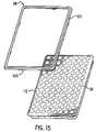
- FIG. 5is an isometric view of the heated cover in accordance with the invention.
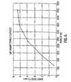
- FIG. 6is a chart depicting the Up Ramp (heating rate) vs. Power.
- FIG. 7is a chart depicting the Down Ramp (cooling rate) vs. Power.
- FIG. 8is a chart for predicting and compensating for temperature overshoots and undershoots in accordance with the invention.
- FIG. 9is a block diagram of the AC resistance measurement circuit of the invention.
- FIG. 10shows a perimeter heater and its location surrounding the sample block.
- FIG. 11is a detailed view of the perimeter heater of FIG. 10 .
- FIG. 12shows the power applied to the perimeter heater as a function of the temperature of the sample block.
- FIG. 13shows a thermal model of a sample in a sample vial.
- FIG. 14is an illustration of the initial conditions of the thermal model of FIG. 13 .
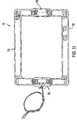
- FIG. 15shows the sample block and a seal designed to protect the thermoelectric devices from the environment.
- PCRit is desirable to change the sample temperature between the required temperatures in the cycle as quickly as possible for several reasons.
- the chemical reactionhas an optimum temperature for each of its stages and as such less time spent at non-optimum temperatures means a better chemical result is achieved.
- a minimum timeis usually required at any given set point which sets a minimum cycle time for each protocol and any time spent in transition between set points adds to this minimum time. Since the number of cycles is usually quite large, this transition time can significantly add to the total time needed to complete the amplification.
- the absolute temperature that each reaction tube attains during each step of the protocolis critical to the yield of product. As the products are frequently subjected to quantitation, the product yield from tube to tube must be as uniform as possible and therefore both the steady-state and dynamic thermal uniformity must be excellent across the block.
- Peltier thermoelectric devicesThese are constructed of pellets of n-type and p-type bismuth telluride connected alternately in series. The interconnections between the pellets is made with copper which is bonded to a substrate, usually a ceramic (typically alumina).
- the amount of heat-pumping requiredis dependent on the thermal load and the ramp rate, that is, the rate at which the temperature is required to change.
- the sample tube geometry and sample volumesare not variables as the sample tubes are established as an industry standard, fitting into many other types of instruments such as centrifuges.
- the sample volumeis defined by user need. Therefore the design variables primarily affect the sample block, thermoelectric devices, heatsink, fan and the thermal interface media between the thermoelectric devices and both the heatsink and the sample block.
- the block geometrymust also meet the necessary thermal uniformity requirements because it is the primary contributor to lateral conduction and therefore evens out any variation in thermal uniformity of the thermoelectric coolers themselves.
- the conflicting requirements of rapid ramp rates (indicating low thermal mass) and high lateral conduction (indicating a large material mass)are met by concentrating the bulk of the block structure in a base plate, and minimizing the thermal mass of the upper portion of the block which holds the sample tubes.
- the optimal material for block fabricationis pure silver which has relatively low thermal mass and very good thermal conduction. Silver also lends itself well to electroforming. In practice the optimal block geometry has a light electroformed upper portion to hold the sample tubes fixed to a relatively thick base plate which provides lateral conduction.
- the thermal mass of the blockis concentrated in the base plate where the material contributes the most to thermal uniformity.
- the electroformed portion of the blockhas a minimum thickness which is defined by two parameters: first, the material cannot be so thin as to make it too delicate for normal handling; second, the wall thickness is required to conduct heat out of the upper regions of the sample tube. Circulation in the sample itself is achieved by convection inside the tube and sample temperature is relatively uniform along the height of the tube, but good thermal conductivity between the tube walls and the base plate increases the effective surface area available for conduction of heat between the sample and the base plate.
- the base plate thicknesshas a minimum value defined by lateral conduction requirements which is a function of the thermal uniformity of the thermoelectric coolers and structural rigidity.
- thermoelectric coolerAnother contributor to the thermal mass is the alumina ceramic layers which form part of the structure of the thermoelectric cooler itself.
- alumina ceramic layerswhich form part of the structure of the thermoelectric cooler itself.
- the thickness of the layersshould be minimized as much as possible, in this case the practical limit of thinness for the alumina thickness is defined by the manufacturing requirements of thermoelectric cooler fabrication.
- This particular layer of ceramiccould in principal be replaced by a different layer altogether such as a thin sheet of Kapton which would reduce the thermal mass even more, but at the present time although coolers are available with this structure, reliability is unproven. It is anticipated that once the technology has been developed further, then a cooler of such a design may be preferred. However, the thin alumina layers also contribute to system reliability.
- the copper conductors within the coolerare a significant thermal load and are not overlooked in the design of the system.
- the thickness of the copper tracesis defined by the requirement of carrying current through the device. Once the current is known the required copper thickness can be calculated.
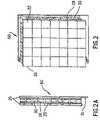
- FIG. 1shows a cross sectional view of a portion of the sample block 36 which typically has 96 wells 20 , each for receiving a sample vial.
- the sample blockis constructed of silver and comprises an upper support plate 21 and the sample wells 20 electroformed as one piece fastened to a base plate 22 .
- the base plate 22provides lateral conduction to compensate for any difference in the thermal power output across the surface of each individual thermoelectric device and for differences from one thermoelectric device to another.
- the center temperatureis reduced by providing a small thermal connection from the center of the sample block to the heat sink.
- a pin 24which acts as a “heat leak” in the center of the sample block, the temperature gradient across the sample block can be reduced to an acceptable level.
- the amount of conduction requiredis quite small and a 1.5 mm diameter stainless steel pin has been found to be sufficient.
- a pin made of the polymer ULTEM, manufactured by General Electricmay also be used. As more fully described below, the pin also serves to help position and lock into place components of the assembly illustrated in FIG. 4 .
- thermoelectric device performanceis critical to PCR performance.
- One of the most significant factors affecting the uniformityis variations in the thermoelectric device performance between devices. The most difficult point at which to achieve good uniformity is during a constant temperature cycle far from ambient. In practice this is a constant temperature cycle at approximately 95° C.
- the thermoelectric devicesare matched tinder these conditions to make a set of devices for each heatsink assembly which individually produce the same temperature for a given input current.
- the thermoelectric devicesare matched to within 0.2° C. in any given set, this value being derived from the maximum discrepancy that can be rectified by the lateral conduction of the sample block baseplate.
- FIG. 2Ashows a side view of a typical Peltier thermal electric device 60 .
- the deviceis composed of bismuth telluride pellets 30 , sandwiched between two alumna layers 26 .
- the pelletsare electrically connected by solder joints 28 to copper traces 29 plated onto the alumina layers.
- One alumina layerhas an extension 31 to facilitate electrical connections. The thickness of the extended areas is reduced to decrease the thermal load of the device.
- FIG. 2shows an isometric view of a typical Peltier thermoelectric device.
- the alumina layer 26that forms the outer wall of the thermoelectric device, expands and contracts during temperature cycling at a different rate than the sample block 19 .
- the motion of the aluminais transmitted directly to the solder 28 connecting the internal bismuth telluride pellets 30 .
- This motioncan be reduced dramatically by cutting the alumina into small pieces 32 called die so that the field of expansion is small.
- the minimum size of the dieis defined by the size of the copper traces required to carry current through the thermoelectric device and the requirements that the device retain some strength for handling.
- Using thin alumina layers in the thermal electric device(of the order of 0.508 mm) not only reduces the thermal load but also means that for a given required heat pumping rate the temperature that the ends of the pellet reaches is reduced due to the increase in thermal conductivity k. This enhances reliability by reducing the thermal stress on the solder joint.
- the reaction temperaturesare above ambient and in the range 35 to 96° C.
- the blockis heated or cooled between two above ambient temperatures where the flow of heat due to conduction is from the block to the heat sink.
- the key to optimizing the system cycle time, given an optimized block configuration,is to balance the boost to the ramp rate when cooling provided by the conduction, against the boost provided to the heating ramp rate by the Joule effect of resistance heating.
- the heating ramp ratewould be increased by increasing the height of the pellet. This is because the conduction path through the thermoelectric device would be made longer thereby decreasing k. This also has the effect of reducing the current required to maintain a given block temperature in the steady state. During the down ramp, i.e. cooling the block, the decreased k means that the conduction contribution will be reduced and so the down ramp rate will be reduced.
- thermoelectric devicecan be derived by adjusting the height of the Bismuth Telluride pellets until the heating rate matches the cooling rate.
- the resistancemust be measured as an AC resistance because of the Seebeck effect. Because the geometry defines the resistance of the device, another design boundary is encountered in that the device must use a cost effective current to voltage ratio because too high a current requirement pushes up the cost of the amplifier.
- the balanced solution for the silver electroformed block described aboveis:
- thermoelectric device geometryIf the thermal cycler was to be used as part of another instrument, e.g. integrated with detection technology, then it may be more convenient to use a different current source which would lead to a modified thermoelectric device geometry.
- the current source in the present embodimentconsists of a class D type switch-mode power amplifier with a current sensing resistor in series with the device and ground.
- thermoelectric devicesare soldered together, excess solder can wick up the side of the bismuth telluride pellets. Where this occurs, k is increased which results in a local cold spot, also called a mild spot. These cold spots are reduced in number and severity by application of the minimum amount of solder during the assembly process of the thermal electric device. For the same reason, it is also necessary to ensure that the solder used to attach the connecting wires to the thermoelectric device does not contact the pellet
- High temperature solderhas been shown to not only have improved high temperature performance but it is also generally more resistant to failure by stress reversals and hence is most appropriate in this application.
- the solder used in this inventionmay be of the type as described in U.S. Pat. No. 5,441,576.
- FIG. 3shows the heatsink 34 assembled with the thermoelectric devices 39 and the sample block 36 .
- a locating frame 41is positioned around the thermoelectric devices to align them with the sample block and the heatsink to ensure temperature uniformity across the sample block.
- the frameis composed of Ultem or other suitable material and has tabs 43 at its corners to facilitate handling.
- the heatsink 34has a generally planer base 34 and fins 37 extending from base 35 .
- the thermal mass of the heat sinkis considerably larger than the thermal mass of the sample block and samples combined.
- the sample block and samples togetherhave a thermal mass of approximately 100 joules/° K and that of the heat sink is approximately 900 joules/° K. This means that the sample block clearly changes temperature much faster than the heat sink for a given amount of heat pumped.
- the heat sink temperatureis controlled with a variable speed fan as shown in FIG. 9 .
- the temperature of the heat sinkis measured by a thermistor 38 placed in a recess 40 within the heatsink and the fan speed is varied to hold the heat sink at approximately 45° C. which is well within the normal PCR cycling temperature range, where maintaining a stable heat sink temperature improves the repeatability of system performance.
- the block temperatureis set to a value below ambient then the heat sink is set to the coolest achievable temperature to reduce system power consumption and optimize block thermal uniformity. This is accomplished simply operating the fan at full speed.
- the heat sink temperature measurementis also used by the thermoelectric device control algorithm described below in linearizing the thermal output power from the thermoelectric devices.
- the heatsink temperature uniformityis reflected in the uniformity of the block temperature. Typically the heatsink is warmer in the middle than it is at the edges and this adds to other effects that lead to the corners of the block being the coldest.
- a trench 44is cut into the heat sink outside the perimeter of the thermoelectric device area to limit the conduction of heat and decreases edge losses from the area bounded by the trench.
- thermoelectric device manufacturersrecommend that thermoelectric devices be held under pressure to improve life-expectancy. (The pressure recommended is often defined by the thermal interface media selected.) The pressure that is recommended varies from manufacturer to manufacturer but is in the range of 30 to 100 psi for cycling applications.
- thermal interface mediaavailable in sheet form which can be used to act as a compliant layer on each side of the thermoelectric devices, but it has been demonstrated that thermal grease gives far superior thermal performance for this application. Unlike other compliant sheets which have been shown to require 30 psi or more even under optimal conditions, thermal grease does not require high pressure to ensure that good thermal contact has been made. Also thermal grease acts as an effective lubricant between the expanding and contracting silver block and the thermoelectric device surface, enhancing life-expectancy. Thermalcote II thermal grease manufactured by Thermalloy, Inc. may be used.
- the silver blockis relatively flexible and so it cannot transmit lateral clamping pressure very effectively.
- the thermal interface mediais thermal grease, the clamping force required is low.
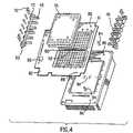
- FIG. 4shows an exploded view of the assembly with the preferred embodiment of the clamping mechanism.
- Each clamp 46is made up of a series of fingers 48 extending from a spine 49 .
- the fingers 48are sized, shaped and spaced so as to fit between the wells 20 of the sample block 36 and thus apply pressure at a corresponding series of points on the base plate 22 of the sample block 36 .
- the open honeycomb structure of the electroformed sample wellsallows the fingers to be inserted some distance into the block, thereby applying the pressure more evenly than an edge clamping scheme would.
- These fingersapply pressure at a series of local points to minimize the contact area between the mass of the clamp and the sample block so that the clamp does not add significantly to the thermal load.
- the clampsare molded from a glass filled plastic which has the necessary rigidity for this application.
- the pressureis applied by deforming the fingers with respect to mounting posts 50 which may be separate clamp structures, but are preferably integrally formed with the clamps 46 .
- the clamps 46are held flush to the surface of the heat sink with a series of screws 52 extending through corresponding hole 53 in clamps 46 and then into threaded holes 55 in heatsink 34 . This scheme eliminates the necessity to set the pressure with adjustment screws as the clamps can simply be tightened down by standard torquing techniques.
- thermoelectric devicesensures that the full area of the thermoelectric devices is in good thermal contact with the block and the heatsink reducing local thermal stresses on the thermoelectric devices.
- FIG. 4shows other important features of the invention.
- a printed circuit board 82includes a memory device 96 for storing data and surrounds the thermoelectric devices and provides electrical connections.
- Alignment pins 84are seated in holes 86 in the heatsink and protrude through alignment holes 88 to align the printed circuit board with the heatsink.
- the locating frame 41is positioned around the thermoelectric devices and has a cross beam 90 with a through hole 92 .
- Pin 24(shown in FIG. 1 ) fits into a hole (not shown) in the sample block, extends through hole 92 in the locating frame and further extends into hole 94 in the heatsink.
- a perimeter heateris positioned around the sample block to eliminate heat losses from its edges.
- the heateris a film type, having low mass with inside dimensions slightly larger than the sample block.
- FIG. 10shows the perimeter heater 74 and its approximate location surrounding the sample block 36 . The heater is not fastened in place, it is simply positioned in the air around the perimeter of the sample block in order to warm the air in the immediate vicinity.
- FIG. 11shows a detailed view of the perimeter heater 74 .
- the heateris rectangular as determined by the dimensions of the sample block and is manufactured so that it has separate power densities in specific areas to reflect the varying amounts of heat loss around the perimeter of the block.
- Matching lower power density regions 76(0.73 W/in 2 ) are located in the center portions of the short sides of the rectangle and matching higher power density regions 78 (1.3 W/in 2 ) are located in the longer sides, extending into the shorter sides.
- the power applied to the perimeter heateris regulated to correspond to the temperature of the sample block, with more power applied to the heater at higher block temperatures and less applied at lower block temperatures.
- FIG. 5shows the heated cover 57 .
- the heated coverapplies pressure to the sample vial caps to ensure that they remain tightly closed when the sample is heated.
- the heated platenhas recesses 56 in it to clear the cap domes, there is a need to align the plate to the tube positions before applying pressure to avoid damage to the tubes. This is accomplished by use of a “skirt” 58 around the perimeter of the platen which aligns to the microtiter tray before the plate touches the tube caps.
- the coverhas a sliding mechanism similar to that used on the PYRIS Differential Scanning Calorimeter by the Perkin Elmer Corporation allowing the cover to slide back to allow sample vials to be inserted into the sample block and forward to cover the sample block and move down engage the vials.
- the optimized ramp ratehas been empirically determined to be 4° C./sec. Any system which has a higher block ramp rate than this cannot fully utilize the benefits of temperature overshoots and consequently achieves an insignificant reduction in cycle time.
- FIG. 6is a chart depicting the Up Ramp (heating rate) vs. Power and FIG. 7 is a chart depicting the Down Ramp (cooling rate) vs. Power.
- the Joule heating and the Seebeck heat pumpingboth act to heat the sample block against conduction.
- the Seebeck heat pumping and conductionact against the Joule heating.
- significant poweris required to hold the block temperature steady against the flow of heat out or the block by conduction. Therefore even with zero power applied, the block will cool at a significant rate.
- the Seebeck effectincreases the cooling obtained.
- the joule effectwhich is proportional to the square of the current, quickly starts to take over acting against the Seebeck cooling. Therefore a point is reached where applying additional power acts against the required effect of cooling. In the heating mode these two effects act together against conduction and no ceiling is reached.
- the heating power vs. input currentis approximately linear. This is why the design criteria centers around meeting the cooling rate requirements; the heating rate can always be achieved by the application of more power.
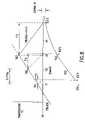
- Input to the PID controlis the error signal t c ⁇ Set point.
- Output from the PID controlis interpreted as a % of Q max .
- Equation 1is used to determine the current value, I, which will result in the % of Q max output by the PID control, under the current temperature conditions.
- Equation 1The solution to equation 1 is used to determine the current value, I, which will result in the desired Q under the current temperature conditions. This process is repeated periodically during temperature transitions.
- the samplehas a time constant with respect to the block temperature that is a function of the sample tube and tube geometry which, because the tube is an industry standard, cannot be reduced. This means that even if the sample tube wall temperature is changed as a step function e.g. by immersion in a water bath, the sample will have a finite ramp time as the sample temperature exponentially approaches the set point. This can be compensated for by dynamically causing the block to overshoot the programmed temperature in a controlled manner. This means that the block temperature is driven beyond the set point and back again as a means of minimizing the time taken for the sample to reach the set point.
- FIG. 8is a chart for predicting and compensating for temperature overshoots and undershoots.
- Tbn+1Ts n +( Tb n+1 ⁇ Ts n )*0.174 /RC
- Tsf n( Tb n ⁇ Ts n ⁇ mRC )(1 ⁇ e ⁇ tm/RC )+ mtr n +Ts n
- Tbthe measured block temperature
- Tsis the calculated sample temperature
- Tsfis the final calculated sample temperature if the block is ramped down at time t n
- Ris the thermal resistance between the sample block and the sample
- Cis the thermal capacitance of the sample
- mis the slope of a line defined by the points Tb and Tsf and tr is the time for the sample block to return to the set point if the system caused it
- the systemcauses the sample block to ramp back to the set point at the same rate it was ramping away. If the resulting Tsf n is outside the particular error window then the system causes the sample block to continue to ramp away from the set point at the same rate. While ramping back toward the set point the same proportional integral derivative (PID) control loop described above is applied.
- PIDproportional integral derivative
- the temperature of a sample in a sample vialis determined by using the model illustrated in FIG. 13 where:
- TSmpcoef1 *TCvr 0+coef2 *T Plastic0+coef3 *TBlk 0+coef4*slope+coef5 *TSmp 0
- T Plasticcoef6 *TCvr 0+coef7 *T Plastic0+coef8*slope+coef9 *TBlk 0+coef10 *TSmp 0
- the coefficientsare recalculated at the beginning of each PCR protocol to account for the currently selected sample volume.
- TSmp and TPlasticare recalculated for every iteration of the control task.
- Tblkis determined using the equation for TSmp.
- Tblk 0( Tsmp ⁇ coef1* TCvr 0 ⁇ coef2 *T Plastic0 ⁇ coef4*slope ⁇ coef5 *TSmp 0)/coef3
- the control softwareincludes calibration diagnostics which permit variation in the performance of thermoelectric coolers from instrument to instrument to be compensated for so that all instruments perform identically.
- the sample block, thermoelectric devices and heatsinkare assembled together and clamped using the clamping mechanism described above.
- the assemblyis then ramped through a series of known temperature profiles during which its actual performance is compared to the specified performance. Adjustments are made to the power supplied to the thermoelectric devices and the process is repeated until actual performance matches the specification.
- the thermal characteristics obtained during this characterization processare then stored in a memory device residing on the assembly. This allows the block assembly to be moved from instrument to instrument and still perform within specifications.
- thermoelectric devicesThe typical failure mode for the thermoelectric devices is an increase in resistance caused by a fatigue failure in a solder joint. This results in an increase in the temperature of that joint which stresses the joint further, rapidly leading to catastrophic failure. It has been determined empirically that devices that exhibit an increase in AC resistance of approximately 5% after about 20,000 to 50,000 temperature cycles will shortly fail. The AC resistance of the thermoelectric devices are monitored by the instrument to detect imminent failures before the device in question causes a thermal uniformity problem.
- This embodimentautomates the actual measurement using a feedback control system and eliminates the need to remove the thermoelectric device from the unit.
- the control systemcompensates for the temperature difference between the two surfaces of the thermoelectric device caused by the heat sink attached to one side and the sample block attached to the other.
- the control systemcauses the thermoelectric device to equalize its two surface temperatures and then the AC resistance measurement is made.
- the micro-controllerperforms a polynomial calculation at the referenced time of the AC measurement to compensate for ambient temperature error.
- FIG. 9shows the sample block 36 , a layer of thermoelectric device 60 and heatsink 34 interfaced with the system microcontroller 62 and bipolar power amplifier 64 .
- the temperature sensoris already present in the heatsink 38 and an additional temperature sensor attached to the sample block 36 with a clip (not shown) formed of music wire are utilized to determine the temperature differential of the surfaces of the thermoelectric device.
- the bipolar power amplifiersupplies current in two directions to the device. Current in one direction heats the sample block and current in the other direction cools the sample block.
- the bipolar power amplifieralso has signal conditioning capability to measure the AC voltage and AC current supplied to the thermoelectric device.
- a band pass filter 68is incorporated into the signal conditioning to separate an AC measurement signal from the steady state signal that produces a null condition for the temperature difference across the thermoelectric device.
- the micro-controllerincorporates the necessary capability to process the measurement information and perform the feedback in real time. It also stores the time history of the AC resistance and the number of temperature cycles of the thermoelectric device and displays the information to the operator on the display 70 .
- the AC measurementis normally done during initial turn on. However, it can be activated when self diagnostics are invoked by the operator using the keypad 72 .
- An analog to digital and digital to analog converter along with signal conditioning for the temperature sensors and AC resistance measurementis also integrated into the micro-controller in order for it to perform its digital signal processing.
- thermoelectric devicesare protected from moisture in the environment by seals and the chamber is kept dry with the use of a drying agent such is silica gel.
- the sealconnects from the silver electroform to the surrounding support and as such adds to the edge losses from the block. These losses are minimized by the use of a low thermal conductivity pressure seal 98 and by the use of the perimeter heater described above.
- the seal 98has a cross-section generally in the shape of a parallelogram with several tabs 100 spaced about the lower surface of seal 98 for holding seal 98 to the edge of the sample block as shown in FIG. 15 .
- the seal 98is installed by first applying RTV rubber (not shown) around the perimeter 110 of the upper portion of the sample block. The seal 98 is then placed on the RTV rubber. More RTV rubber is applied to the perimeter 120 of the seal and then a cover (not shown) is installed which contacts the RTV rubber-seal combination. The cover has a skirt which also contacts a gasket (not shown) on the printed circuit board to effect a more effective seal.
Landscapes
- Chemical & Material Sciences (AREA)
- Engineering & Computer Science (AREA)
- Health & Medical Sciences (AREA)
- Life Sciences & Earth Sciences (AREA)
- Physics & Mathematics (AREA)
- Chemical Kinetics & Catalysis (AREA)
- Organic Chemistry (AREA)
- General Health & Medical Sciences (AREA)
- Biochemistry (AREA)
- Molecular Biology (AREA)
- Zoology (AREA)
- Proteomics, Peptides & Aminoacids (AREA)
- General Physics & Mathematics (AREA)
- General Engineering & Computer Science (AREA)
- Wood Science & Technology (AREA)
- Clinical Laboratory Science (AREA)
- Microbiology (AREA)
- Immunology (AREA)
- Bioinformatics & Cheminformatics (AREA)
- Biotechnology (AREA)
- Biophysics (AREA)
- Genetics & Genomics (AREA)
- Analytical Chemistry (AREA)
- Automation & Control Theory (AREA)
- Mechanical Engineering (AREA)
- Thermal Sciences (AREA)
- Apparatus Associated With Microorganisms And Enzymes (AREA)
Abstract
Description
R=nr(h/A)
where n is the number of pellets, r is the resistivity of the Bismuth Telluride being used, h is the height of the pellet and A is the cross-sectional area.
- Pellet height=1.27 mm
- Pellet cross-sectional area=5.95 mm2
0=½*R(tavg)*I2+tc*S(tavg)*I−(k(tavg)*(tc−th)+Qc)
where
- tc=cold side temperature of cooler
- th=hot side temperature of cooler
- tavg=average of tcand th
- R(t)=electrical resistance of cooler as a function of temperature
- S(t)=Seebeck coefficient of the cooler as a function of temperature
- K(t)=Conductance of cooler as function of temperature
- I=electrical current applied to cooler
- Qc=total heat flow from the cold side of the cooler
Q=MCp*dT/dt
Tsn+1=Tsn+(Tbn+1−Tsn)*0.174/RC
Tsfn=(Tbn−Tsn−mRC)(1−e−tm/RC)+mtrn+Tsn
where Tb is the measured block temperature, Ts is the calculated sample temperature, Tsf is the final calculated sample temperature if the block is ramped down at time tn, R is the thermal resistance between the sample block and the sample, C is the thermal capacitance of the sample, m is the slope of a line defined by the points Tb and Tsf and tr is the time for the sample block to return to the set point if the system caused it to ramp toward the set point at the same rate it is was ramping away.
- TBlk is the measured baseplate temperature;
- TSmp is the calculated sample temperature;
- TPlastic is the calculated plastic temperature;
- TCvr is the measured cover temperature;
- R1 is the thermal resistance of the plastic vial between the block and sample mixture;
- C1 is the thermal capacitance of the sample mixture;
- R2 and R3 represent the thermal resistance of air in parallel with the plastic vial between the sample mixture and the cover; and
- C2 is the thermal capacitance of the plastic vial between the sample mixture and the cover.
g1=1/R1;
g2=1/R2;
g3=1/R3;
a=(g1+g2)/C1;
b=g2/C1;
f=g2/C2;
g=(g2+g3)/C2;
alpha=−(−g/2−a/2−(sqrt(g*g−2*g*a+a*a+4*f*b))/2); and
beta=−(−g/2−a/2+(sqrt(g*g−2*g*a+a*a+4*f*b))/2),
the coefficients for the sample temperature equation become:
coef1=(g3/C2)*(−b/(beta*(alpha−beta))*exp(−beta*T)+b/(alpha*beta)+(b/(alpha*(alpha−beta)))*exp(−alpha*T))
coef2=(b/(alpha−beta))*exp(−beta*T)−(b/(alpha−beta))*exp(−alpha*T)
coef3=(g1/C1)*(g/(alpha*beta)+(−alpha+g)*exp(−alpha*T)/(alpha*(alpha−beta))+(beta−g)*exp(−beta*T)/(beta*(alpha−beta)))
coef4=(g1/C1)*((g−beta)*exp(−beta*T)/(pow(beta,2)*(alpha−beta))−g/(beta*pow(alpha,2))+(1+T*g)/(alpha*beta)+(−g+alpha)*exp(−alpha*T)/(pow(alpha,2)*(alpha−beta))−g/(alpha*pow(beta,2)))
coef5=(−g+alpha)*exp(−alpha*T)/(alpha−beta)+(g−beta)*exp(−beta*T)/(alpha−beta)
and the coefficients for the plastic vial temperature equation become:
coef6=(g3/C2)*((beta−a)*exp(−beta*T)/(beta*(alpha−beta))+a/(alpha*beta)+(−alpha+a)*exp(−alpha*T)/(alpha*(alpha−beta)))
coef7=(−beta+a)*exp(−beta*T)/(alpha−beta)+(alpha−a)*exp(−alpha*T)/(alpha−beta)
coef8=(g1/C1)*(f*exp(−beta*T)/(pow(beta,2)*(alpha−beta))−f/(beta*pow(alpha,2))−f*exp(−alpha*T/(pow(alpha,2)*(alpha−beta))+T*f/(alpha*beta)−f/(alpha*pow(beta,2)))
coef9=(g1/C1)*(−f*exp(−beta*T)/(beta*(alpha−beta))+f/(alpha*beta)+f*exp(−alpha*T)/(alpha*(alpha−beta)))
coef10=f*exp(−beta*T)/(alpha−beta)−f*exp(−alpha*T)/(alpha−beta)
and
slope=(TBlk−TBlk0)/Twhere T is the sampling period (0.174 sec)
Utilizing the model in
TSmp=coef1*TCvr0+coef2*TPlastic0+coef3*TBlk0+coef4*slope+coef5*TSmp0
TPlastic=coef6*TCvr0+coef7*TPlastic0+coef8*slope+coef9*TBlk0+coef10*TSmp0
Tblk0=(Tsmp−coef1*TCvr0−coef2*TPlastic0−coef4*slope−coef5*TSmp0)/coef3
TBlkSP=(TSmpSP−coef1*TCvr−coef2*TPlastic−coef5*TSmpSP)/coef3
Claims (20)
Priority Applications (2)
| Application Number | Priority Date | Filing Date | Title |
|---|---|---|---|
| US11/804,298US7645070B2 (en) | 1997-03-28 | 2007-05-17 | Thermal cycler for PCR |
| US12/686,100US8246243B2 (en) | 1997-03-28 | 2010-01-12 | Thermal cycler for PCR |
Applications Claiming Priority (6)
| Application Number | Priority Date | Filing Date | Title |
|---|---|---|---|
| US4175497P | 1997-03-28 | 1997-03-28 | |
| US4612297P | 1997-05-09 | 1997-05-09 | |
| PCT/US1998/006189WO1998043740A2 (en) | 1997-03-28 | 1998-03-30 | Improvements in thermal cycler for pcr |
| US09/075,392US7133726B1 (en) | 1997-03-28 | 1998-05-08 | Thermal cycler for PCR |
| US11/057,960US7537377B2 (en) | 1997-03-28 | 2005-02-15 | Thermal cycler for PCR |
| US11/804,298US7645070B2 (en) | 1997-03-28 | 2007-05-17 | Thermal cycler for PCR |
Related Parent Applications (1)
| Application Number | Title | Priority Date | Filing Date |
|---|---|---|---|
| US11/057,960ContinuationUS7537377B2 (en) | 1997-03-28 | 2005-02-15 | Thermal cycler for PCR |
Related Child Applications (1)
| Application Number | Title | Priority Date | Filing Date |
|---|---|---|---|
| US12/686,100ContinuationUS8246243B2 (en) | 1997-03-28 | 2010-01-12 | Thermal cycler for PCR |
Publications (2)
| Publication Number | Publication Date |
|---|---|
| US20070230535A1 US20070230535A1 (en) | 2007-10-04 |
| US7645070B2true US7645070B2 (en) | 2010-01-12 |
Family
ID=34714218
Family Applications (8)
| Application Number | Title | Priority Date | Filing Date |
|---|---|---|---|
| US09/075,392Expired - Fee RelatedUS7133726B1 (en) | 1997-03-28 | 1998-05-08 | Thermal cycler for PCR |
| US11/057,960Expired - LifetimeUS7537377B2 (en) | 1997-03-28 | 2005-02-15 | Thermal cycler for PCR |
| US11/654,238Expired - Fee RelatedUS8685717B2 (en) | 1997-03-28 | 2007-01-17 | Thermal cycler for PCR |
| US11/654,239Expired - Fee RelatedUS9044753B2 (en) | 1997-03-28 | 2007-01-17 | Thermal cycler for PCR |
| US11/804,298Expired - Fee RelatedUS7645070B2 (en) | 1997-03-28 | 2007-05-17 | Thermal cycler for PCR |
| US12/229,404Expired - Fee RelatedUS9776187B2 (en) | 1997-03-28 | 2008-08-22 | Thermal cycler for PCR |
| US12/686,100Expired - Fee RelatedUS8246243B2 (en) | 1997-03-28 | 2010-01-12 | Thermal cycler for PCR |
| US13/619,746AbandonedUS20130078713A1 (en) | 1997-03-28 | 2012-09-14 | Thermal Cycler For PCR |
Family Applications Before (4)
| Application Number | Title | Priority Date | Filing Date |
|---|---|---|---|
| US09/075,392Expired - Fee RelatedUS7133726B1 (en) | 1997-03-28 | 1998-05-08 | Thermal cycler for PCR |
| US11/057,960Expired - LifetimeUS7537377B2 (en) | 1997-03-28 | 2005-02-15 | Thermal cycler for PCR |
| US11/654,238Expired - Fee RelatedUS8685717B2 (en) | 1997-03-28 | 2007-01-17 | Thermal cycler for PCR |
| US11/654,239Expired - Fee RelatedUS9044753B2 (en) | 1997-03-28 | 2007-01-17 | Thermal cycler for PCR |
Family Applications After (3)
| Application Number | Title | Priority Date | Filing Date |
|---|---|---|---|
| US12/229,404Expired - Fee RelatedUS9776187B2 (en) | 1997-03-28 | 2008-08-22 | Thermal cycler for PCR |
| US12/686,100Expired - Fee RelatedUS8246243B2 (en) | 1997-03-28 | 2010-01-12 | Thermal cycler for PCR |
| US13/619,746AbandonedUS20130078713A1 (en) | 1997-03-28 | 2012-09-14 | Thermal Cycler For PCR |
Country Status (1)
| Country | Link |
|---|---|
| US (8) | US7133726B1 (en) |
Cited By (10)
| Publication number | Priority date | Publication date | Assignee | Title |
|---|---|---|---|---|
| US20070117200A1 (en)* | 1997-03-28 | 2007-05-24 | Applera Corporation | Thermal cycler for PCR |
| US20090119057A1 (en)* | 2005-04-22 | 2009-05-07 | Boian Todorov Alexandrov | Method and device for investigation of phase transformations in metals and alloys |
| WO2011130785A1 (en) | 2010-04-20 | 2011-10-27 | Corbett Research Pty Ltd | Temperature control method and apparatus |
| US20120155504A1 (en)* | 2010-09-30 | 2012-06-21 | Delaware Capital Formation, Inc. | Apparatus and method for determining phase separation risk of a blended fuel in a storage tank |
| US20130121368A1 (en)* | 2010-04-23 | 2013-05-16 | Snecma | Device evaluating thermomechanical fatigue of a material |
| US8795592B2 (en) | 2010-09-23 | 2014-08-05 | Analogic Corporation | Sample thermal cycling |
| CN105642382A (en)* | 2016-04-01 | 2016-06-08 | 东莞威铁克自动化科技有限公司 | Medical heating table |
| US9448121B2 (en) | 2012-04-10 | 2016-09-20 | Industrial Technology Research Institute | Measurement method, measurement apparatus, and computer program product |
| US10544966B2 (en) | 2015-07-23 | 2020-01-28 | Cepheid | Thermal control device and methods of use |
| US20230042912A1 (en)* | 2018-08-08 | 2023-02-09 | Panasonic Intellectual Property Management Co., Ltd. | Heat amount measuring method and heat amount measuring apparatus |
Families Citing this family (108)
| Publication number | Priority date | Publication date | Assignee | Title |
|---|---|---|---|---|
| US6893877B2 (en) | 1998-01-12 | 2005-05-17 | Massachusetts Institute Of Technology | Methods for screening substances in a microwell array |
| WO2000056456A1 (en) | 1999-03-19 | 2000-09-28 | Genencor International, Inc. | Multi-through hole testing plate for high throughput screening |
| US20020151040A1 (en) | 2000-02-18 | 2002-10-17 | Matthew O' Keefe | Apparatus and methods for parallel processing of microvolume liquid reactions |
| US7867763B2 (en) | 2004-01-25 | 2011-01-11 | Fluidigm Corporation | Integrated chip carriers with thermocycler interfaces and methods of using the same |
| US8277753B2 (en) | 2002-08-23 | 2012-10-02 | Life Technologies Corporation | Microfluidic transfer pin |
| US7682565B2 (en) | 2002-12-20 | 2010-03-23 | Biotrove, Inc. | Assay apparatus and method using microfluidic arrays |
| US20060094108A1 (en)* | 2002-12-20 | 2006-05-04 | Karl Yoder | Thermal cycler for microfluidic array assays |
| US8293471B2 (en) | 2004-01-28 | 2012-10-23 | Marshall University Research Corporation | Apparatus and method for a continuous rapid thermal cycle system |
| AU2005222618A1 (en) | 2004-03-12 | 2005-09-29 | Biotrove, Inc. | Nanoliter array loading |
| US7665815B2 (en)* | 2004-04-30 | 2010-02-23 | Fujifilm Dimatix, Inc. | Droplet ejection apparatus alignment |
| US7659109B2 (en)* | 2004-05-17 | 2010-02-09 | Applied Biosystems, Llc | Pasting edge heater |
| US20060030036A1 (en) | 2004-05-28 | 2006-02-09 | Victor Joseph | Chips for multiplex analyses |
| EP1710017B1 (en) | 2005-04-04 | 2012-12-19 | Roche Diagnostics GmbH | Thermocycling of a block comprising multiple samples |
| JP4187259B2 (en)* | 2005-10-04 | 2008-11-26 | キヤノン株式会社 | Pressure support mechanism of structure |
| US10741034B2 (en) | 2006-05-19 | 2020-08-11 | Apdn (B.V.I.) Inc. | Security system and method of marking an inventory item and/or person in the vicinity |
| EP2057435A4 (en)* | 2006-06-23 | 2011-04-20 | Life Technologies Corp | Systems and methods for cooling in biological analysis instruments |
| EP2082061B8 (en)* | 2006-10-06 | 2020-10-07 | Applied DNA Sciences, Inc. | Method for a continuous rapid thermal cycle system |
| US8696724B2 (en)* | 2007-01-11 | 2014-04-15 | Scion Neurostim, Llc. | Devices for vestibular or cranial nerve stimulation |
| US20080168775A1 (en)* | 2007-01-11 | 2008-07-17 | Nextreme Thermal Solutions, Inc. | Temperature Control Including Integrated Thermoelectric Temperature Sensing and Related Methods and Systems |
| US20080264464A1 (en)* | 2007-01-11 | 2008-10-30 | Nextreme Thermal Solutions, Inc. | Temperature Control Including Integrated Thermoelectric Sensing and Heat Pumping Devices and Related Methods and Systems |
| US8267983B2 (en)* | 2007-01-11 | 2012-09-18 | Scion Neurostim, Llc. | Medical devices incorporating thermoelectric transducer and controller |
| JP2010516281A (en) | 2007-01-22 | 2010-05-20 | ウェハージェン,インコーポレイテッド | High-throughput chemical reaction equipment |
| EP2137319B1 (en) | 2007-03-21 | 2018-07-25 | Applied Biosystems, LLC | Adaptive thermal block temperature control method and system |
| US20080306633A1 (en)* | 2007-06-07 | 2008-12-11 | Dell Products L.P. | Optimized power and airflow multistage cooling system |
| TW200912265A (en)* | 2007-09-12 | 2009-03-16 | Unisense Technology Co Ltd | Adjustment method and adjustment system for temperature sensing component |
| PE20090965A1 (en)* | 2007-10-12 | 2009-07-13 | Bigtec Private Ltd | MICRO CHIP |
| US8460621B2 (en)* | 2007-10-15 | 2013-06-11 | Biocision, Llc | Temperature transfer stand |
| EP2060324A1 (en)* | 2007-11-13 | 2009-05-20 | F.Hoffmann-La Roche Ag | Thermal block unit |
| DE202007018930U1 (en) | 2007-11-28 | 2009-11-19 | Nickl, Julius, Dr. | Thermal oscillation for the cyclic tempering of biological medical and chemical samples |
| US8612064B2 (en)* | 2008-01-24 | 2013-12-17 | Hewlett-Packard Development Company, L.P. | Human user interface device with thermal controls |
| CN101534624B (en)* | 2008-03-14 | 2012-10-10 | 富准精密工业(深圳)有限公司 | Radiator combination |
| JP4703702B2 (en)* | 2008-09-17 | 2011-06-15 | 株式会社東芝 | Damage index prediction system and damage index prediction method |
| US20100081191A1 (en)* | 2008-09-26 | 2010-04-01 | Marlow Industries, Inc. | Anisotropic heat spreader for use with a thermoelectric device |
| EP2198968B1 (en) | 2008-12-16 | 2018-10-17 | F. Hoffmann-La Roche AG | Systems and methods for monitoring a thermoelectric heating and cooling device |
| ES2390987T3 (en)* | 2008-12-18 | 2012-11-20 | F. Hoffmann-La Roche Ag | Method for checking the thermal coupling quality of a measuring cell |
| WO2012033396A1 (en)* | 2008-12-18 | 2012-03-15 | Universiti Sains Malaysia | A disposable multiplex polymerase chain reaction (pcr) chip and device |
| US9399219B2 (en)* | 2009-02-13 | 2016-07-26 | Frank Leo Spangler | Thermal Array |
| CN202830041U (en)* | 2009-04-03 | 2013-03-27 | Illumina公司 | Device for heating biological sample |
| EP2454381A1 (en)* | 2009-07-16 | 2012-05-23 | Abbott Laboratories | A method for amplification of nucleic acids |
| GB2511692A (en)* | 2009-08-08 | 2014-09-10 | Bibby Scient Ltd | An apparatus for treating a test sample |
| GB2472455B (en)* | 2009-08-08 | 2016-07-06 | Bibby Scient Ltd | A method of controlling an apparatus having a thermoelectric cooler |
| CN102471746B (en)* | 2009-08-20 | 2013-07-10 | 宝生物工程有限公司 | Temperature cycling device |
| DE202010013705U1 (en) | 2009-09-01 | 2010-12-02 | Life Technologies Corp., Carlsbad | Thermoblock groups and instruments that provide low thermal non-uniformity for fast thermal cycling |
| EP2473893B1 (en)* | 2009-09-01 | 2021-07-28 | Life Technologies Corporation | Thermal block assemblies and instruments providing low thermal non-uniformity for rapid thermal cycling |
| CN201837588U (en)* | 2009-09-09 | 2011-05-18 | 海利克斯公司 | Optical system for multiple reactions |
| EP3375891B1 (en) | 2009-09-10 | 2020-02-19 | DiaSorin S.p.A. | Methods and devices for compensation of spectral crosstalk in multiplex nucleic acid amplification |
| WO2011075574A1 (en) | 2009-12-18 | 2011-06-23 | Scion Neurostim, Llc | Devices and methods for vestibular and/or cranial nerve stimulation |
| EP2332654B1 (en) | 2009-12-09 | 2014-04-02 | F. Hoffmann-La Roche AG | System and method for cycling liquid samples through a series of temperature excursions |
| EP2338599B1 (en)* | 2009-12-23 | 2013-11-20 | Eppendorf Ag | Laboratory apparatus with an arrangement for the tempering of samples and method of tempering samples |
| EP2353722A1 (en)* | 2010-02-09 | 2011-08-10 | F. Hoffmann-La Roche AG | Heat dissipation of power electronics for thermocyclers |
| US8301408B2 (en) | 2010-03-09 | 2012-10-30 | Invensys Systems, Inc. | Temperature prediction transmitter |
| DE102010019232B4 (en)* | 2010-05-03 | 2013-06-27 | Eppendorf Ag | Avoid condensation hood |
| US20110308271A1 (en) | 2010-06-18 | 2011-12-22 | Biocision, Inc. | Specimen freezing rate regulator device |
| CN103415346B (en) | 2010-12-08 | 2016-09-07 | 生命技术公司 | Control systems and methods for biological applications |
| US10537467B2 (en) | 2010-12-16 | 2020-01-21 | Scion Neurostim, Llc | Systems, devices and methods for bilateral caloric vestibular stimulation |
| JP6580298B2 (en) | 2010-12-16 | 2019-09-25 | サイオン・ニューロスティム,リミテッド・ライアビリティ・カンパニー | Vestibular stimulation device and vestibular stimulation system |
| US9744074B2 (en) | 2010-12-16 | 2017-08-29 | Scion Neurostim, Llc | Combination treatments |
| US10512564B2 (en) | 2010-12-16 | 2019-12-24 | Scion Neurostim, Llc | Combination treatments |
| IT1403791B1 (en)* | 2010-12-30 | 2013-10-31 | St Microelectronics Srl | METHOD FOR CALIBRATING A TEMPERATURE SENSOR OF A CHEMICAL MICROREACTOR AND ANALYZER FOR BIOCHEMICAL ANALYSIS |
| TW201239089A (en)* | 2011-03-22 | 2012-10-01 | Genereach Biotechnology Corp | Convective polymerase chain reaction device |
| TW201239088A (en)* | 2011-03-22 | 2012-10-01 | Genereach Biotechnology Corp | Convective polymerase chain reaction device |
| US10928321B2 (en) | 2012-03-09 | 2021-02-23 | Ubiquitome Limited | Portable device for detecting molecule(s) |
| ES2805354T3 (en) | 2012-05-15 | 2021-02-11 | Cepheid | Thermal cycling apparatus and method |
| US9180461B2 (en) | 2012-10-22 | 2015-11-10 | Qiagen Gaithersburg, Inc. | Condensation-reducing incubation cover |
| USD735881S1 (en) | 2012-10-22 | 2015-08-04 | Qiagen Gaithersburg, Inc. | Tube strip holder for automated processing systems |
| US20140112829A1 (en)* | 2012-10-22 | 2014-04-24 | Qiagen Gaithersburg, Inc. | Tube strip handling and heating apparatus |
| US9963740B2 (en) | 2013-03-07 | 2018-05-08 | APDN (B.V.I.), Inc. | Method and device for marking articles |
| US20160051982A1 (en)* | 2013-03-08 | 2016-02-25 | Otago Innovation Limited | Reaction vessel holder and molecule detection device |
| US9352502B2 (en) | 2013-06-25 | 2016-05-31 | Lawrence Livermore National Security, Llc | Porous media heat transfer for injection molding |
| US9904734B2 (en) | 2013-10-07 | 2018-02-27 | Apdn (B.V.I.) Inc. | Multimode image and spectral reader |
| GB201319759D0 (en)* | 2013-11-08 | 2013-12-25 | Thomsen Lars | Device and method for heating a fluid chamber |
| KR20150053488A (en)* | 2013-11-08 | 2015-05-18 | 한국전자통신연구원 | thermoelectric conductivity measurement instrument of thermoelectric device and measuring method of the same |
| EP3119610B1 (en) | 2014-03-18 | 2024-05-22 | APDN (B.V.I.) Inc. | Encrypted optical markers for security applications |
| US10745825B2 (en) | 2014-03-18 | 2020-08-18 | Apdn (B.V.I.) Inc. | Encrypted optical markers for security applications |
| GB2526520B (en) | 2014-04-04 | 2021-08-18 | It Is Int Ltd | Biochemical reaction system |
| EP3549675A1 (en) | 2014-06-19 | 2019-10-09 | Akonni Biosystems, Inc. | Molecular analysis system and use thereof |
| EP3259602B9 (en) | 2015-02-20 | 2021-05-19 | Takara Bio USA, Inc. | Method for rapid accurate dispensing, visualization and analysis of single cells |
| EP3090845A1 (en)* | 2015-05-08 | 2016-11-09 | Braun GmbH | Method for adjusting the maximum cooling temperature of a cooling element of a user electrical appliance and user electrical appliance |
| EP3124881A1 (en)* | 2015-07-28 | 2017-02-01 | Siemens Aktiengesellschaft | Peltier air dehumidifer for installation in a container |
| CN106468725A (en)* | 2015-08-14 | 2017-03-01 | 致茂电子股份有限公司 | Probe structure |
| JP6903638B2 (en)* | 2015-09-15 | 2021-07-14 | ライフ テクノロジーズ コーポレーション | Systems and methods for biological analysis |
| US11583862B2 (en) | 2015-09-15 | 2023-02-21 | Life Technologies Corporation | Systems and methods for biological analysis |
| DK3356046T3 (en) | 2015-10-01 | 2022-02-14 | Berkeley Lights Inc | WELL PLATE INCUBATOR |
| EP3394293B1 (en) | 2015-12-22 | 2021-05-26 | Canon U.S. Life Sciences, Inc. | Sample-to-answer system for microorganism detection featuring target enrichment, amplification and detection |
| EP3217168A1 (en)* | 2016-03-08 | 2017-09-13 | Roche Diagnostics GmbH | Test element analysis system for the analytical examination of a sample |
| US11285478B2 (en) | 2016-04-04 | 2022-03-29 | Combinati Incorporated | Microfluidic siphoning array for nucleic acid quantification |
| CN109070130B (en) | 2016-04-11 | 2022-03-22 | 亚普蒂恩(B V I)公司 | Method for marking cellulose products |
| US11460405B2 (en) | 2016-07-21 | 2022-10-04 | Takara Bio Usa, Inc. | Multi-Z imaging and dispensing with multi-well devices |
| EP3516082A4 (en)* | 2016-09-23 | 2020-07-01 | Archerdx, Inc. | System for nucleic acid preparation |
| US10995371B2 (en) | 2016-10-13 | 2021-05-04 | Apdn (B.V.I.) Inc. | Composition and method of DNA marking elastomeric material |
| EP3548602B1 (en)* | 2016-12-01 | 2024-09-25 | Bruker Cellular Analysis, Inc. | Well-plate incubator |
| US10920274B2 (en) | 2017-02-21 | 2021-02-16 | Apdn (B.V.I.) Inc. | Nucleic acid coated submicron particles for authentication |
| CN108873979B (en)* | 2017-05-12 | 2020-08-07 | 台达电子工业股份有限公司 | Thermal control device and thermal control method thereof |
| NL2020622B1 (en)* | 2018-01-24 | 2019-07-30 | Lllumina Cambridge Ltd | Reduced dimensionality structured illumination microscopy with patterned arrays of nanowells |
| US20220048033A1 (en)* | 2018-09-14 | 2022-02-17 | William Marsh Rice University | Apparatus and methods for multiplexed amplification and detection of dna using convectional heating and label-free microarray |
| KR102204931B1 (en)* | 2019-03-12 | 2021-01-20 | 퓨쳐이엔지 주식회사 | Thermal cycler sample block with function of selective temperature control for PCR |
| CN109929753B (en)* | 2019-03-14 | 2019-11-08 | 宁波胤瑞生物医学仪器有限责任公司 | A kind of blower fan module digitizing nucleic acid augmentative instrument |
| DE102019106699B4 (en) | 2019-03-15 | 2024-01-25 | Analytik Jena Gmbh+Co. Kg | Device and method for the thermal treatment of samples |
| DE102019124588A1 (en)* | 2019-09-12 | 2021-03-18 | Biometra GmbH | Temperature control device |
| WO2021101850A1 (en)* | 2019-11-18 | 2021-05-27 | Deepdivebio, Inc. | Thermocycler temperature control |
| KR102786503B1 (en)* | 2019-11-22 | 2025-03-26 | 주식회사 씨젠 | Sample holder transport device used in thermal cycler |
| CN115698327A (en)* | 2020-06-15 | 2023-02-03 | 生物辐射实验室股份有限公司 | Temperature uniformity across PCR sample blocks |
| WO2022195289A2 (en) | 2021-03-19 | 2022-09-22 | Bg Research Ltd | An apparatus and associated methods for thermal cycling |
| US12163833B2 (en)* | 2021-06-01 | 2024-12-10 | Si-Ware Systems | Large spot size spectrometer |
| CN114015561B (en)* | 2021-11-05 | 2023-11-14 | 中元汇吉生物技术股份有限公司 | PCR fluorescent detection temperature control system |
| WO2024107618A1 (en)* | 2022-11-16 | 2024-05-23 | 10X Genomics, Inc. | Systems and methods for thermal management of reagent well plates |
| CN117129511B (en)* | 2023-09-18 | 2024-04-12 | 安徽工程大学 | Terahertz online monitoring device and method for thermal fatigue behavior of thermal barrier coating |
| WO2025127693A1 (en)* | 2023-12-13 | 2025-06-19 | Seegene, Inc. | Thermal cycler |
Citations (56)
| Publication number | Priority date | Publication date | Assignee | Title |
|---|---|---|---|---|
| US3075377A (en)* | 1956-10-17 | 1963-01-29 | Owens Corning Fiberglass Corp | Apparatus for determining thermal conductivity of materials |
| US3552185A (en)* | 1968-10-09 | 1971-01-05 | Dow Chemical Co | Thermal conductivity apparatus |
| US3733887A (en)* | 1972-01-31 | 1973-05-22 | Borg Warner | Method and apparatus for measuring the thermal conductivity and thermo-electric properties of solid materials |
| US3842346A (en)* | 1972-12-20 | 1974-10-15 | C Bobbitt | Continuity testing of solid state circuitry during temperature cycling |
| GB2146464A (en)* | 1983-09-09 | 1985-04-17 | Mannesmann Ag | Heating furnace control |
| US4530608A (en)* | 1984-05-14 | 1985-07-23 | The Perkin-Elmer Corp. | Baseline control for a differential scanning calorimeter |
| US4639883A (en) | 1984-11-28 | 1987-01-27 | Rca Corporation | Thermoelectric cooling system and method |
| EP0236069A2 (en) | 1986-02-25 | 1987-09-09 | The Perkin-Elmer Corporation | Apparatus and method for performing automated amplification of nucleic acid sequences and assays using heating and cooling steps |
| GB2188163A (en)* | 1986-03-18 | 1987-09-23 | British Petroleum Co Plc | Testing degradation of a sample under thermal cycling |
| US4865986A (en) | 1988-10-06 | 1989-09-12 | Coy Corporation | Temperature control apparatus |
| US4881038A (en) | 1988-05-25 | 1989-11-14 | Champlin Keith S | Electric battery testing device with automatic voltage scaling to determine dynamic conductance |
| EP0342155A2 (en) | 1988-05-13 | 1989-11-15 | Agrogen-Stiftung | Laboratory device for optional heating and cooling |
| EP0362173A1 (en) | 1988-09-29 | 1990-04-04 | Telub Teknik Ab | A method to measure a temperature with a peltier element |
| US4967382A (en)* | 1987-01-09 | 1990-10-30 | Hall Burness C | Programmable time varying control system and method |
| US5005129A (en)* | 1988-02-29 | 1991-04-02 | Fuji Jukogyo Kabushiki Kaisha | Diagnosis system for a motor vehicle |
| DE4037955A1 (en) | 1989-12-05 | 1991-06-06 | Bernd Seidl | Sample container holder - having several holding vessels on hot plate pref. made of high thermal conductivity, low heat capacity material e.g. silver |
| US5038852A (en)* | 1986-02-25 | 1991-08-13 | Cetus Corporation | Apparatus and method for performing automated amplification of nucleic acid sequences and assays using heating and cooling steps |
| US5040381A (en) | 1990-04-19 | 1991-08-20 | Prime Computer, Inc. | Apparatus for cooling circuits |
| US5080495A (en)* | 1989-08-30 | 1992-01-14 | Mitsui Toatsu Chemicals, Inc. | Method and apparatus for measuring thermal diffusivity by ac joule-heating |
| EP0488769A2 (en) | 1990-11-29 | 1992-06-03 | The Perkin-Elmer Corporation | Thermal cycler for automatic performance of the polymerase chain reaction with close temperature control |
| JPH0560708A (en)* | 1991-08-30 | 1993-03-12 | Toshiba Corp | Calorimeter for thermal vacuum test |
| WO1993009486A1 (en) | 1991-11-05 | 1993-05-13 | Hybaid Limited | Reaction temperature control device |
| US5237821A (en) | 1987-08-20 | 1993-08-24 | Kabushiki Kaisha Komatsu Seisakusho | Multistep electronic cooler |
| US5248934A (en) | 1992-01-10 | 1993-09-28 | Roveti Denes K | Method and apparatus for converting a conventional DC multimeter to an AC impedance meter |
| US5255976A (en)* | 1992-07-10 | 1993-10-26 | Vertex Pharmaceuticals Incorporated | Temperature gradient calorimeter |
| US5282543A (en) | 1990-11-29 | 1994-02-01 | The Perkin Elmer Corporation | Cover for array of reaction tubes |
| US5318361A (en)* | 1993-06-01 | 1994-06-07 | Bell Communications Research, Inc. | Rapid temperature cycling for accelerated stress testing |
| US5333675A (en) | 1986-02-25 | 1994-08-02 | Hoffmann-La Roche Inc. | Apparatus and method for performing automated amplification of nucleic acid sequences and assays using heating and cooling steps |
| US5385022A (en) | 1993-09-09 | 1995-01-31 | Kornblit; Levy | Apparatus and method for deep thermoelectric refrigeration |
| EP0640828A1 (en) | 1993-08-27 | 1995-03-01 | F. Hoffmann-La Roche AG | Monitoring multiple reactions simultaneously and analyzing same |
| EP0642831A1 (en) | 1993-09-10 | 1995-03-15 | F. Hoffmann-La Roche Ag | Device for automatically carrying out temperature cycling |
| EP0642828A1 (en) | 1993-09-10 | 1995-03-15 | F. Hoffmann-La Roche Ag | Array of reaction vessels for a device for automatically carrying out temperature cycling |
| US5410130A (en) | 1994-04-20 | 1995-04-25 | Ericomp, Inc. | Heating and temperature cycling |
| US5431021A (en) | 1992-11-27 | 1995-07-11 | Gwilliam; Scott B. | Thermoelectric device with a plurality of modules individually controlled |
| US5441576A (en) | 1993-02-01 | 1995-08-15 | Bierschenk; James L. | Thermoelectric cooler |
| WO1995027196A1 (en) | 1994-04-04 | 1995-10-12 | Sanadi Ashok R | Method and apparatus for preventing cross-contamination of multi-well test plates |
| US5525300A (en)* | 1993-10-20 | 1996-06-11 | Stratagene | Thermal cycler including a temperature gradient block |
| US5568977A (en)* | 1993-02-24 | 1996-10-29 | Imra Europe Sa | Process and device to detect a risk of water condensation on a surface being in contact with a wet air volume |
| US5600575A (en) | 1994-10-05 | 1997-02-04 | Anticole; Robert B. | Drive protection monitor for motor and amplifier |
| WO1997021089A1 (en) | 1995-12-05 | 1997-06-12 | The Perkin-Elmer Corporation | Optical cuvette |
| US5711604A (en)* | 1993-12-14 | 1998-01-27 | Seiko Instruments Inc. | Method for measuring the coefficient of heat conductivity of a sample |
| US5736333A (en) | 1996-06-04 | 1998-04-07 | The Perkin-Elmer Corporation | Passive internal references for the detection of nucleic acid amplification products |
| US5744975A (en)* | 1996-06-06 | 1998-04-28 | International Business Machines Corporation | Enhanced defect elimination process for electronic assemblies via application of sequentially combined multiple stress processes |
| US5756878A (en)* | 1995-01-24 | 1998-05-26 | Yamatake-Honeywell Co., Ltd. | Thermal conductivity measuring device |
| US5928907A (en) | 1994-04-29 | 1999-07-27 | The Perkin-Elmer Corporation., Applied Biosystems Division | System for real time detection of nucleic acid amplification products |
| US6019505A (en)* | 1997-12-31 | 2000-02-01 | Honeywell Inc. | Time lag approach for measuring thermal conductivity and specific heat |
| US6228634B1 (en)* | 1997-03-03 | 2001-05-08 | Regents Of The University Of Minnesota | Thermal cycling or temperature control device and method using alumina plate |
| US6331075B1 (en)* | 1998-05-01 | 2001-12-18 | Administrator, National Aeronautics And Space Administration | Device and method for measuring thermal conductivity of thin films |
| US6429007B1 (en)* | 1997-05-02 | 2002-08-06 | BIOMéRIEUX, INC. | Nucleic acid amplification reaction station for disposable test devices |
| US20020191826A1 (en)* | 2000-01-04 | 2002-12-19 | The Regents Of The University Of California | Polymerase chain reaction system |
| US20030036189A1 (en)* | 1998-11-25 | 2003-02-20 | The Regents Of The University Of California | PCR thermocycler |
| US7051536B1 (en)* | 2004-11-12 | 2006-05-30 | Bio-Rad Laboratories, Inc. | Thermal cycler with protection from atmospheric moisture |
| US20070014695A1 (en)* | 2005-04-26 | 2007-01-18 | Applera Corporation | Systems and Methods for Multiple Analyte Detection |
| US20070289314A1 (en)* | 2006-06-14 | 2007-12-20 | Fluke Corporation | Temperature calibration device having reconfigurable heating/cooling modules to provide wide temperature range |
| US20080124723A1 (en)* | 2006-06-30 | 2008-05-29 | Canon U.S. Life Sciences, Inc. | Combined thermal devices for thermal cycling |
| US7504241B2 (en)* | 1990-11-29 | 2009-03-17 | Applied Biosystems, Llc | Thermal cycler for automatic performance of the polymerase chain reaction with close temperature control |
Family Cites Families (68)
| Publication number | Priority date | Publication date | Assignee | Title |
|---|---|---|---|---|
| US2146464A (en)* | 1936-08-26 | 1939-02-07 | Charles D Briddell | Attachment for animal traps |
| US2188163A (en)* | 1939-02-13 | 1940-01-23 | Sherman Jack | Shower curtain holder |
| US3182391A (en)* | 1960-02-29 | 1965-05-11 | Westinghouse Electric Corp | Process of preparing thermoelectric elements |
| US3210216A (en)* | 1962-02-09 | 1965-10-05 | Westinghouse Electric Corp | Brazing gold alloy and thermoelectric device produced therewith |
| US3821058A (en)* | 1972-05-25 | 1974-06-28 | Edn Corp | Harness cable lacing tool |
| US3766360A (en)* | 1972-08-07 | 1973-10-16 | Biospectrum Inc | Laboratory hot plate |
| DE2450482C1 (en) | 1974-10-24 | 1985-10-31 | Messerschmitt-Bölkow-Blohm GmbH, 8000 München | Heated centrifuge |
| US3998592A (en) | 1975-12-24 | 1976-12-21 | Ford Motor Company | Thermoelectric heat pump for chemiluminescence detectors |
| US4149025A (en) | 1977-11-16 | 1979-04-10 | Vasile Niculescu | Method of fabricating thermoelectric power generator modules |
| US4231256A (en)* | 1979-02-05 | 1980-11-04 | Beckman Instruments, Inc. | Thermoelectric gas dryer |
| DE3044372A1 (en)* | 1980-11-25 | 1982-07-08 | Boehringer Mannheim Gmbh, 6800 Mannheim | ROTOR UNIT WITH INSERT ELEMENTS FOR A CENTRIFUGAL ANALYZER |
| US4574876A (en) | 1981-05-11 | 1986-03-11 | Extracorporeal Medical Specialties, Inc. | Container with tapered walls for heating or cooling fluids |
| US4632908A (en) | 1984-05-03 | 1986-12-30 | Abbott Laboratories | Heating system for rotating members |
| US5656493A (en)* | 1985-03-28 | 1997-08-12 | The Perkin-Elmer Corporation | System for automated performance of the polymerase chain reaction |
| US4676951A (en)* | 1985-07-01 | 1987-06-30 | American Hospital Supply Corp. | Automatic specimen analyzing system |
| DE3626734A1 (en) | 1986-08-07 | 1988-02-11 | Bosch Gmbh Robert | MACHINE FOR SORTING, FILLING AND SEALING HOLLOW BODIES |
| IT210435Z2 (en)* | 1987-01-30 | 1988-12-30 | S I C M E S P A Societa Ind Co | VERTICAL OVEN FOR THE COOKING OF FILIFFORM Artifacts |
| US4878108A (en)* | 1987-06-15 | 1989-10-31 | International Business Machines Corporation | Heat dissipation package for integrated circuits |
| US4782664A (en) | 1987-09-16 | 1988-11-08 | Allied Products Corporation | Thermoelectric heat exchanger |
| US5155336A (en)* | 1990-01-19 | 1992-10-13 | Applied Materials, Inc. | Rapid thermal heating apparatus and method |
| IE903986A1 (en) | 1990-04-24 | 1991-11-06 | Lancet Sa | Cooking device |
| US6787338B2 (en)* | 1990-06-04 | 2004-09-07 | The University Of Utah | Method for rapid thermal cycling of biological samples |
| US5436172A (en)* | 1991-05-20 | 1995-07-25 | Texas Instruments Incorporated | Real-time multi-zone semiconductor wafer temperature and process uniformity control system |
| US5224778A (en)* | 1991-11-12 | 1993-07-06 | The Perkin Elmer Corporation | Temperature verification for polymerase chain reaction systems |
| US5232667A (en) | 1992-05-21 | 1993-08-03 | Diametrics Medical, Inc. | Temperature control for portable diagnostic system using a non-contact temperature probe |
| US5495093A (en)* | 1993-02-05 | 1996-02-27 | Edsyn, Inc. | Soldering apparatus processor having temperature selection, calibration and heating control of tip |
| US5364790A (en)* | 1993-02-16 | 1994-11-15 | The Perkin-Elmer Corporation | In situ PCR amplification system |
| ATE208658T1 (en)* | 1993-07-28 | 2001-11-15 | Pe Corp Ny | APPARATUS AND METHOD FOR NUCLEIC ACID DUPLICATION |
| US5834828A (en)* | 1993-09-20 | 1998-11-10 | The United States Of America, As Represented By The Secretary Of The Army | Nanoporous semiconductor material and fabrication technique for use as thermoelectric elements |
| EP0678917B1 (en)* | 1994-04-22 | 2003-06-25 | Nec Corporation | Supporting member for cooling means and electronic package using the same |
| EP0685860A1 (en)* | 1994-06-03 | 1995-12-06 | Hewlett-Packard Company | Full travel, sealed, fully backlighted keyboard |
| US5621615A (en)* | 1995-03-31 | 1997-04-15 | Hewlett-Packard Company | Low cost, high thermal performance package for flip chips with low mechanical stress on chip |
| US5679457A (en) | 1995-05-19 | 1997-10-21 | The Bergquist Company | Thermally conductive interface for electronic devices |
| JP3951315B2 (en)* | 1995-05-26 | 2007-08-01 | 松下電工株式会社 | Peltier module |
| US5849208A (en) | 1995-09-07 | 1998-12-15 | Microfab Technoologies, Inc. | Making apparatus for conducting biochemical analyses |
| JP3724857B2 (en)* | 1995-09-18 | 2005-12-07 | 株式会社瀬田技研 | Temperature control device and start method for electromagnetic induction heating device |
| US5710733A (en)* | 1996-01-22 | 1998-01-20 | Silicon Graphics, Inc. | Processor-inclusive memory module |
| US6635492B2 (en) | 1996-01-25 | 2003-10-21 | Bjs Company Ltd. | Heating specimen carriers |
| US5914065A (en)* | 1996-03-18 | 1999-06-22 | Alavi; Kamal | Apparatus and method for heating a fluid by induction heating |
| DE19622402C1 (en) | 1996-06-04 | 1997-10-16 | Siemens Ag | Substrate induction heating apparatus especially for CVD |
| WO1997048818A1 (en)* | 1996-06-17 | 1997-12-24 | The Board Of Trustees Of The Leland Stanford Junior University | Thermocycling apparatus and method |
| US5973299A (en)* | 1996-11-01 | 1999-10-26 | Ta Instruments, Inc. | System and method for heater control for evaporation of cryogenic fluids for cooling scientific instruments |
| US5882903A (en)* | 1996-11-01 | 1999-03-16 | Sarnoff Corporation | Assay system and method for conducting assays |
| US8293064B2 (en) | 1998-03-02 | 2012-10-23 | Cepheid | Method for fabricating a reaction vessel |
| US7133726B1 (en) | 1997-03-28 | 2006-11-07 | Applera Corporation | Thermal cycler for PCR |
| EP2913109A1 (en) | 1997-03-28 | 2015-09-02 | Applera Corporation | Assembly for thermal cycler for PCR |
| US5857480A (en)* | 1997-09-26 | 1999-01-12 | Klein; Jerry | Water purging system |
| US6818437B1 (en) | 1998-05-16 | 2004-11-16 | Applera Corporation | Instrument for monitoring polymerase chain reaction of DNA |
| US6348176B1 (en)* | 1999-02-11 | 2002-02-19 | Careside, Inc. | Cartridge-based analytical instrument using centrifugal force/pressure for metering/transport of fluids |
| US7387891B2 (en)* | 1999-05-17 | 2008-06-17 | Applera Corporation | Optical instrument including excitation source |
| DE29917313U1 (en)* | 1999-10-01 | 2001-02-15 | MWG-BIOTECH AG, 85560 Ebersberg | Device for carrying out chemical or biological reactions |
| US6482638B1 (en) | 1999-12-09 | 2002-11-19 | 3M Innovative Properties Company | Heat-relaxable substrates and arrays |
| AU2001247478A1 (en)* | 2000-03-16 | 2001-09-24 | Sri International | Microlaboratory devices and methods |
| US6783934B1 (en) | 2000-05-01 | 2004-08-31 | Cepheid, Inc. | Methods for quantitative analysis of nucleic acid amplification reaction |
| US6734401B2 (en)* | 2000-06-28 | 2004-05-11 | 3M Innovative Properties Company | Enhanced sample processing devices, systems and methods |
| US6717118B2 (en)* | 2001-06-26 | 2004-04-06 | Husky Injection Molding Systems, Ltd | Apparatus for inductive and resistive heating of an object |
| JP2004537147A (en)* | 2001-07-24 | 2004-12-09 | マグ テック エルエルシー | Magnetic heater device and method |
| US7635588B2 (en) | 2001-11-29 | 2009-12-22 | Applied Biosystems, Llc | Apparatus and method for differentiating multiple fluorescence signals by excitation wavelength |
| US6889468B2 (en) | 2001-12-28 | 2005-05-10 | 3M Innovative Properties Company | Modular systems and methods for using sample processing devices |
| US6677151B2 (en)* | 2002-01-30 | 2004-01-13 | Applera Corporation | Device and method for thermal cycling |
| KR100459896B1 (en)* | 2002-03-06 | 2004-12-04 | 삼성전자주식회사 | Thermostatic control Method and apparatus for Driving a PCR(polymerize chain reaction) chip |
| DE10221763A1 (en)* | 2002-05-15 | 2003-12-04 | Eppendorf Ag | Thermal cycler with temperature control block controlled in cycles |
| US6859050B2 (en)* | 2002-05-31 | 2005-02-22 | Agilent Technologies, Inc. | High frequency contactless heating with temperature and/or conductivity monitoring |
| DE10228431B4 (en) | 2002-06-26 | 2004-08-26 | Eppendorf Ag | Laboratory sample temperature control device with recordings |
| US20040241048A1 (en)* | 2003-05-30 | 2004-12-02 | Applera Corporation | Thermal cycling apparatus and method for providing thermal uniformity |
| US7585663B2 (en) | 2004-08-26 | 2009-09-08 | Applied Biosystems, Llc | Thermal device, system, and method, for fluid processing device |
| US8232091B2 (en) | 2006-05-17 | 2012-07-31 | California Institute Of Technology | Thermal cycling system |
| US20100124766A1 (en) | 2008-11-14 | 2010-05-20 | Life Technologies Corporation | Apparatus and Method for Segmented Thermal Cycler |
- 1998
- 1998-05-08USUS09/075,392patent/US7133726B1/ennot_activeExpired - Fee Related
- 2005
- 2005-02-15USUS11/057,960patent/US7537377B2/ennot_activeExpired - Lifetime
- 2007
- 2007-01-17USUS11/654,238patent/US8685717B2/ennot_activeExpired - Fee Related
- 2007-01-17USUS11/654,239patent/US9044753B2/ennot_activeExpired - Fee Related
- 2007-05-17USUS11/804,298patent/US7645070B2/ennot_activeExpired - Fee Related
- 2008
- 2008-08-22USUS12/229,404patent/US9776187B2/ennot_activeExpired - Fee Related
- 2010
- 2010-01-12USUS12/686,100patent/US8246243B2/ennot_activeExpired - Fee Related
- 2012
- 2012-09-14USUS13/619,746patent/US20130078713A1/ennot_activeAbandoned
Patent Citations (70)
| Publication number | Priority date | Publication date | Assignee | Title |
|---|---|---|---|---|
| US3075377A (en)* | 1956-10-17 | 1963-01-29 | Owens Corning Fiberglass Corp | Apparatus for determining thermal conductivity of materials |
| US3552185A (en)* | 1968-10-09 | 1971-01-05 | Dow Chemical Co | Thermal conductivity apparatus |
| US3733887A (en)* | 1972-01-31 | 1973-05-22 | Borg Warner | Method and apparatus for measuring the thermal conductivity and thermo-electric properties of solid materials |
| US3842346A (en)* | 1972-12-20 | 1974-10-15 | C Bobbitt | Continuity testing of solid state circuitry during temperature cycling |
| GB2146464A (en)* | 1983-09-09 | 1985-04-17 | Mannesmann Ag | Heating furnace control |
| US4530608A (en)* | 1984-05-14 | 1985-07-23 | The Perkin-Elmer Corp. | Baseline control for a differential scanning calorimeter |
| US4639883A (en) | 1984-11-28 | 1987-01-27 | Rca Corporation | Thermoelectric cooling system and method |
| EP0236069A2 (en) | 1986-02-25 | 1987-09-09 | The Perkin-Elmer Corporation | Apparatus and method for performing automated amplification of nucleic acid sequences and assays using heating and cooling steps |
| US5333675A (en) | 1986-02-25 | 1994-08-02 | Hoffmann-La Roche Inc. | Apparatus and method for performing automated amplification of nucleic acid sequences and assays using heating and cooling steps |
| US5333675C1 (en) | 1986-02-25 | 2001-05-01 | Perkin Elmer Corp | Apparatus and method for performing automated amplification of nucleic acid sequences and assays using heating and cooling steps |
| US5038852A (en)* | 1986-02-25 | 1991-08-13 | Cetus Corporation | Apparatus and method for performing automated amplification of nucleic acid sequences and assays using heating and cooling steps |
| GB2188163A (en)* | 1986-03-18 | 1987-09-23 | British Petroleum Co Plc | Testing degradation of a sample under thermal cycling |
| US4967382A (en)* | 1987-01-09 | 1990-10-30 | Hall Burness C | Programmable time varying control system and method |
| US5237821A (en) | 1987-08-20 | 1993-08-24 | Kabushiki Kaisha Komatsu Seisakusho | Multistep electronic cooler |
| US5005129A (en)* | 1988-02-29 | 1991-04-02 | Fuji Jukogyo Kabushiki Kaisha | Diagnosis system for a motor vehicle |
| EP0342155A2 (en) | 1988-05-13 | 1989-11-15 | Agrogen-Stiftung | Laboratory device for optional heating and cooling |
| US5061630A (en) | 1988-05-13 | 1991-10-29 | Agrogen Foundation, Seyffer & Co. & Ulrich C. Knopf | Laboratory apparatus for optional temperature-controlled heating and cooling |
| US4881038A (en) | 1988-05-25 | 1989-11-14 | Champlin Keith S | Electric battery testing device with automatic voltage scaling to determine dynamic conductance |
| EP0362173A1 (en) | 1988-09-29 | 1990-04-04 | Telub Teknik Ab | A method to measure a temperature with a peltier element |
| US4865986A (en) | 1988-10-06 | 1989-09-12 | Coy Corporation | Temperature control apparatus |
| US5080495A (en)* | 1989-08-30 | 1992-01-14 | Mitsui Toatsu Chemicals, Inc. | Method and apparatus for measuring thermal diffusivity by ac joule-heating |
| DE4037955A1 (en) | 1989-12-05 | 1991-06-06 | Bernd Seidl | Sample container holder - having several holding vessels on hot plate pref. made of high thermal conductivity, low heat capacity material e.g. silver |
| US5040381A (en) | 1990-04-19 | 1991-08-20 | Prime Computer, Inc. | Apparatus for cooling circuits |
| EP0488769A2 (en) | 1990-11-29 | 1992-06-03 | The Perkin-Elmer Corporation | Thermal cycler for automatic performance of the polymerase chain reaction with close temperature control |
| US7504241B2 (en)* | 1990-11-29 | 2009-03-17 | Applied Biosystems, Llc | Thermal cycler for automatic performance of the polymerase chain reaction with close temperature control |
| US5475610A (en) | 1990-11-29 | 1995-12-12 | The Perkin-Elmer Corporation | Thermal cycler for automatic performance of the polymerase chain reaction with close temperature control |
| US5282543A (en) | 1990-11-29 | 1994-02-01 | The Perkin Elmer Corporation | Cover for array of reaction tubes |
| EP1510823A2 (en) | 1990-11-29 | 2005-03-02 | Applera Corporation | Containers for performing polymerase chain reaction |
| JPH06233670A (en) | 1990-11-29 | 1994-08-23 | Perkin Elmer Corp:The | Automatic device for causing chain reaction of polymerase using temperature control |
| EP1510823A3 (en) | 1990-11-29 | 2005-07-06 | Applera Corporation | Containers for performing polymerase chain reaction |
| JPH0560708A (en)* | 1991-08-30 | 1993-03-12 | Toshiba Corp | Calorimeter for thermal vacuum test |
| WO1993009486A1 (en) | 1991-11-05 | 1993-05-13 | Hybaid Limited | Reaction temperature control device |
| US5248934A (en) | 1992-01-10 | 1993-09-28 | Roveti Denes K | Method and apparatus for converting a conventional DC multimeter to an AC impedance meter |
| US5255976A (en)* | 1992-07-10 | 1993-10-26 | Vertex Pharmaceuticals Incorporated | Temperature gradient calorimeter |
| US5431021A (en) | 1992-11-27 | 1995-07-11 | Gwilliam; Scott B. | Thermoelectric device with a plurality of modules individually controlled |
| US5441576A (en) | 1993-02-01 | 1995-08-15 | Bierschenk; James L. | Thermoelectric cooler |
| US5568977A (en)* | 1993-02-24 | 1996-10-29 | Imra Europe Sa | Process and device to detect a risk of water condensation on a surface being in contact with a wet air volume |
| US5318361A (en)* | 1993-06-01 | 1994-06-07 | Bell Communications Research, Inc. | Rapid temperature cycling for accelerated stress testing |
| EP0640828A1 (en) | 1993-08-27 | 1995-03-01 | F. Hoffmann-La Roche AG | Monitoring multiple reactions simultaneously and analyzing same |
| JPH07163397A (en) | 1993-08-27 | 1995-06-27 | F Hoffmann La Roche Ag | Simultaneous observation and analysis method for multiple amplification reactions |
| US5385022A (en) | 1993-09-09 | 1995-01-31 | Kornblit; Levy | Apparatus and method for deep thermoelectric refrigeration |
| JPH07151764A (en) | 1993-09-10 | 1995-06-16 | F Hoffmann La Roche Ag | A device that automatically performs temperature cycling on multiple test tubes |
| US5795547A (en)* | 1993-09-10 | 1998-08-18 | Roche Diagnostic Systems, Inc. | Thermal cycler |
| EP0642831A1 (en) | 1993-09-10 | 1995-03-15 | F. Hoffmann-La Roche Ag | Device for automatically carrying out temperature cycling |
| US5616301A (en)* | 1993-09-10 | 1997-04-01 | Hoffmann-La Roche Inc. | Thermal cycler |
| EP0642828A1 (en) | 1993-09-10 | 1995-03-15 | F. Hoffmann-La Roche Ag | Array of reaction vessels for a device for automatically carrying out temperature cycling |
| US5720406A (en) | 1993-09-10 | 1998-02-24 | Roche Diagnostic Systems, Inc. | Reaction container arrangement for use in a thermal cycler |
| JPH07167865A (en) | 1993-09-10 | 1995-07-04 | F Hoffmann La Roche Ag | A collection of single-use reaction vessels of the same shape and size to cause a cyclic temperature change in a liquid mixture in the reaction vessel. |
| EP0642828B1 (en) | 1993-09-10 | 1998-05-20 | F. Hoffmann-La Roche Ag | Array of reaction vessels for a device for automatically carrying out temperature cycling |
| US5525300A (en)* | 1993-10-20 | 1996-06-11 | Stratagene | Thermal cycler including a temperature gradient block |
| US6054263A (en)* | 1993-10-20 | 2000-04-25 | Stratagene | Thermal cycler including a temperature gradient block |
| US5711604A (en)* | 1993-12-14 | 1998-01-27 | Seiko Instruments Inc. | Method for measuring the coefficient of heat conductivity of a sample |
| WO1995027196A1 (en) | 1994-04-04 | 1995-10-12 | Sanadi Ashok R | Method and apparatus for preventing cross-contamination of multi-well test plates |
| US5410130A (en) | 1994-04-20 | 1995-04-25 | Ericomp, Inc. | Heating and temperature cycling |
| US5928907A (en) | 1994-04-29 | 1999-07-27 | The Perkin-Elmer Corporation., Applied Biosystems Division | System for real time detection of nucleic acid amplification products |
| US5600575A (en) | 1994-10-05 | 1997-02-04 | Anticole; Robert B. | Drive protection monitor for motor and amplifier |
| US5756878A (en)* | 1995-01-24 | 1998-05-26 | Yamatake-Honeywell Co., Ltd. | Thermal conductivity measuring device |
| WO1997021089A1 (en) | 1995-12-05 | 1997-06-12 | The Perkin-Elmer Corporation | Optical cuvette |
| US5736333A (en) | 1996-06-04 | 1998-04-07 | The Perkin-Elmer Corporation | Passive internal references for the detection of nucleic acid amplification products |
| US5744975A (en)* | 1996-06-06 | 1998-04-28 | International Business Machines Corporation | Enhanced defect elimination process for electronic assemblies via application of sequentially combined multiple stress processes |
| US6228634B1 (en)* | 1997-03-03 | 2001-05-08 | Regents Of The University Of Minnesota | Thermal cycling or temperature control device and method using alumina plate |
| US6429007B1 (en)* | 1997-05-02 | 2002-08-06 | BIOMéRIEUX, INC. | Nucleic acid amplification reaction station for disposable test devices |
| US6019505A (en)* | 1997-12-31 | 2000-02-01 | Honeywell Inc. | Time lag approach for measuring thermal conductivity and specific heat |
| US6331075B1 (en)* | 1998-05-01 | 2001-12-18 | Administrator, National Aeronautics And Space Administration | Device and method for measuring thermal conductivity of thin films |
| US20030036189A1 (en)* | 1998-11-25 | 2003-02-20 | The Regents Of The University Of California | PCR thermocycler |
| US20020191826A1 (en)* | 2000-01-04 | 2002-12-19 | The Regents Of The University Of California | Polymerase chain reaction system |
| US7051536B1 (en)* | 2004-11-12 | 2006-05-30 | Bio-Rad Laboratories, Inc. | Thermal cycler with protection from atmospheric moisture |
| US20070014695A1 (en)* | 2005-04-26 | 2007-01-18 | Applera Corporation | Systems and Methods for Multiple Analyte Detection |
| US20070289314A1 (en)* | 2006-06-14 | 2007-12-20 | Fluke Corporation | Temperature calibration device having reconfigurable heating/cooling modules to provide wide temperature range |
| US20080124723A1 (en)* | 2006-06-30 | 2008-05-29 | Canon U.S. Life Sciences, Inc. | Combined thermal devices for thermal cycling |
Non-Patent Citations (2)
| Title |
|---|
| Paul D. Levine, et al., "Precision AC Measurements of Temperature Below 90 K," IEEE Transactions on Instrumentation and Measurement, Apr. 1989. |
| Two European Search Reports, both mailed Oct. 28, 1998, for European Application No. EP 03 022 674.4-2113 (4 pages + 9 pages). |
Cited By (21)
| Publication number | Priority date | Publication date | Assignee | Title |
|---|---|---|---|---|
| US20070117200A1 (en)* | 1997-03-28 | 2007-05-24 | Applera Corporation | Thermal cycler for PCR |
| US20070113880A1 (en)* | 1997-03-28 | 2007-05-24 | Applera Corporation | Thermal cycler for PCR |
| US20080314431A1 (en)* | 1997-03-28 | 2008-12-25 | Applied Biosystems, Inc. | Thermal cycler for PCR |
| US9776187B2 (en) | 1997-03-28 | 2017-10-03 | Applied Biosystems, Llc | Thermal cycler for PCR |
| US8685717B2 (en) | 1997-03-28 | 2014-04-01 | Applied Biosystems, Llc | Thermal cycler for PCR |
| US9044753B2 (en) | 1997-03-28 | 2015-06-02 | Applied Biosystems, Llc | Thermal cycler for PCR |
| US20090119057A1 (en)* | 2005-04-22 | 2009-05-07 | Boian Todorov Alexandrov | Method and device for investigation of phase transformations in metals and alloys |
| US7909505B2 (en)* | 2005-04-22 | 2011-03-22 | The Ohio State University | Method and device for investigation of phase transformations in metals and alloys |
| WO2011130785A1 (en) | 2010-04-20 | 2011-10-27 | Corbett Research Pty Ltd | Temperature control method and apparatus |
| US9501070B2 (en) | 2010-04-20 | 2016-11-22 | Qiagen Instruments Ag | Temperature control method and apparatus |
| US8979360B2 (en)* | 2010-04-23 | 2015-03-17 | Snecma | Device evaluating thermomechanical fatigue of a material |
| US20130121368A1 (en)* | 2010-04-23 | 2013-05-16 | Snecma | Device evaluating thermomechanical fatigue of a material |
| US8795592B2 (en) | 2010-09-23 | 2014-08-05 | Analogic Corporation | Sample thermal cycling |
| US9557314B2 (en)* | 2010-09-30 | 2017-01-31 | Delaware Capital Formation, Inc. | Apparatus and method for determining phase separation risk of a blended fuel in a storage tank |
| US20120155504A1 (en)* | 2010-09-30 | 2012-06-21 | Delaware Capital Formation, Inc. | Apparatus and method for determining phase separation risk of a blended fuel in a storage tank |
| US9448121B2 (en) | 2012-04-10 | 2016-09-20 | Industrial Technology Research Institute | Measurement method, measurement apparatus, and computer program product |
| US10544966B2 (en) | 2015-07-23 | 2020-01-28 | Cepheid | Thermal control device and methods of use |
| US11073310B2 (en) | 2015-07-23 | 2021-07-27 | Cepheid | Thermal control device and methods of use |
| US12196460B2 (en) | 2015-07-23 | 2025-01-14 | Cepheid | Thermal control device and methods of use |
| CN105642382A (en)* | 2016-04-01 | 2016-06-08 | 东莞威铁克自动化科技有限公司 | Medical heating table |
| US20230042912A1 (en)* | 2018-08-08 | 2023-02-09 | Panasonic Intellectual Property Management Co., Ltd. | Heat amount measuring method and heat amount measuring apparatus |
Also Published As
| Publication number | Publication date |
|---|---|
| US20070113880A1 (en) | 2007-05-24 |
| US9776187B2 (en) | 2017-10-03 |
| US9044753B2 (en) | 2015-06-02 |
| US20100173400A1 (en) | 2010-07-08 |
| US20050145273A1 (en) | 2005-07-07 |
| US20070117200A1 (en) | 2007-05-24 |
| US7537377B2 (en) | 2009-05-26 |
| US20080314431A1 (en) | 2008-12-25 |
| US20070230535A1 (en) | 2007-10-04 |
| US8685717B2 (en) | 2014-04-01 |
| US8246243B2 (en) | 2012-08-21 |
| US7133726B1 (en) | 2006-11-07 |
| US20130078713A1 (en) | 2013-03-28 |
Similar Documents
| Publication | Publication Date | Title |
|---|---|---|
| US7645070B2 (en) | Thermal cycler for PCR | |
| EP2090366B1 (en) | Improvements in thermal cycler for PCR | |
| WO1998043740A9 (en) | Improvements in thermal cycler for pcr | |
| US8859271B2 (en) | Thermal cycling apparatus and method for providing thermal uniformity | |
| US20200124548A1 (en) | High sample throughput differential scanning calorimeter | |
| EP2338599B1 (en) | Laboratory apparatus with an arrangement for the tempering of samples and method of tempering samples | |
| EP1127619B1 (en) | Assembly for thermal cycler for PCR | |
| EP1386666B1 (en) | Improvements in thermal cycler for pcr | |
| CA2464973A1 (en) | Thermal cycler for pcr | |
| WO2025061910A1 (en) | Thermal control device for temperature cycling, method for controlling temperature cycling using a thermal control device, and system for controlling temperature of a sample using a thermal control device |
Legal Events
| Date | Code | Title | Description |
|---|---|---|---|
| AS | Assignment | Owner name:BANK OF AMERICA, N.A, AS COLLATERAL AGENT, WASHING Free format text:SECURITY AGREEMENT;ASSIGNOR:APPLIED BIOSYSTEMS, LLC;REEL/FRAME:021976/0001 Effective date:20081121 Owner name:BANK OF AMERICA, N.A, AS COLLATERAL AGENT,WASHINGT Free format text:SECURITY AGREEMENT;ASSIGNOR:APPLIED BIOSYSTEMS, LLC;REEL/FRAME:021976/0001 Effective date:20081121 | |
| AS | Assignment | Owner name:APPLIED BIOSYSTEMS INC., CALIFORNIA Free format text:CHANGE OF NAME;ASSIGNOR:APPLERA CORPORATION;REEL/FRAME:022889/0486 Effective date:20080630 Owner name:APPLIED BIOSYSTEMS INC., CALIFORNIA Free format text:MERGER;ASSIGNOR:ATOM ACQUISITION CORPORATION;REEL/FRAME:022889/0504 Effective date:20081121 Owner name:APPLIED BIOSYSTEMS, LLC, CALIFORNIA Free format text:MERGER;ASSIGNOR:ATOM ACQUISITION, LLC AND APPLIED BIOSYSTEMS INC.;REEL/FRAME:022889/0514 Effective date:20081121 | |
| STCF | Information on status: patent grant | Free format text:PATENTED CASE | |
| FPAY | Fee payment | Year of fee payment:4 | |
| AS | Assignment | Owner name:APPLIED BIOSYSTEMS, INC., CALIFORNIA Free format text:LIEN RELEASE;ASSIGNOR:BANK OF AMERICA, N.A.;REEL/FRAME:030182/0677 Effective date:20100528 | |
| AS | Assignment | Owner name:APPLIED BIOSYSTEMS, LLC, CALIFORNIA Free format text:CORRECTIVE ASSIGNMENT TO CORRECT THE RECEIVING PARTY NAME PREVIOUSLY RECORDED AT REEL: 030182 FRAME: 0689. ASSIGNOR(S) HEREBY CONFIRMS THE RELEASE OF SECURITY INTEREST;ASSIGNOR:BANK OF AMERICA, N.A.;REEL/FRAME:038000/0397 Effective date:20100528 Owner name:APPLIED BIOSYSTEMS, LLC, CALIFORNIA Free format text:CORRECTIVE ASSIGNMENT TO CORRECT THE RECEIVING PARTY NAME PREVIOUSLY RECORDED AT REEL: 030182 FRAME: 0677. ASSIGNOR(S) HEREBY CONFIRMS THE RELEASE OF SECURITY INTEREST;ASSIGNOR:BANK OF AMERICA, N.A.;REEL/FRAME:038000/0397 Effective date:20100528 | |
| FPAY | Fee payment | Year of fee payment:8 | |
| FEPP | Fee payment procedure | Free format text:MAINTENANCE FEE REMINDER MAILED (ORIGINAL EVENT CODE: REM.); ENTITY STATUS OF PATENT OWNER: LARGE ENTITY | |
| LAPS | Lapse for failure to pay maintenance fees | Free format text:PATENT EXPIRED FOR FAILURE TO PAY MAINTENANCE FEES (ORIGINAL EVENT CODE: EXP.); ENTITY STATUS OF PATENT OWNER: LARGE ENTITY | |
| STCH | Information on status: patent discontinuation | Free format text:PATENT EXPIRED DUE TO NONPAYMENT OF MAINTENANCE FEES UNDER 37 CFR 1.362 | |
| FP | Lapsed due to failure to pay maintenance fee | Effective date:20220112 |