US7642451B2 - Thermally tuned coaxial cable for microwave antennas - Google Patents
Thermally tuned coaxial cable for microwave antennasDownload PDFInfo
- Publication number
- US7642451B2 US7642451B2US12/351,633US35163309AUS7642451B2US 7642451 B2US7642451 B2US 7642451B2US 35163309 AUS35163309 AUS 35163309AUS 7642451 B2US7642451 B2US 7642451B2
- Authority
- US
- United States
- Prior art keywords
- inner conductor
- coaxial cable
- outer conductor
- conductor
- thermal expansion
- Prior art date
- Legal status (The legal status is an assumption and is not a legal conclusion. Google has not performed a legal analysis and makes no representation as to the accuracy of the status listed.)
- Active
Links
- 239000004020conductorSubstances0.000claimsabstractdescription193
- 239000003989dielectric materialSubstances0.000claimsabstractdescription56
- 239000000463materialSubstances0.000claimsdescription79
- 238000010438heat treatmentMethods0.000claimsdescription32
- 229910001285shape-memory alloyInorganic materials0.000claimsdescription16
- 125000006850spacer groupChemical group0.000claimsdescription15
- 230000008859changeEffects0.000claimsdescription12
- 238000000034methodMethods0.000claimsdescription12
- 239000012530fluidSubstances0.000claimsdescription7
- 239000000203mixtureSubstances0.000claimsdescription7
- 229920000642polymerPolymers0.000claimsdescription7
- 239000004810polytetrafluoroethyleneSubstances0.000claimsdescription7
- 229920001343polytetrafluoroethylenePolymers0.000claimsdescription7
- 239000004677NylonSubstances0.000claimsdescription6
- 229920001778nylonPolymers0.000claimsdescription6
- 229920001470polyketonePolymers0.000claimsdescription6
- 230000001105regulatory effectEffects0.000claimsdescription6
- 239000004698PolyethyleneSubstances0.000claimsdescription5
- VYPSYNLAJGMNEJ-UHFFFAOYSA-NSilicium dioxideChemical compoundO=[Si]=OVYPSYNLAJGMNEJ-UHFFFAOYSA-N0.000claimsdescription5
- 230000001276controlling effectEffects0.000claimsdescription5
- 229920000573polyethylenePolymers0.000claimsdescription5
- -1PolyethylenePolymers0.000claimsdescription4
- VGGSQFUCUMXWEO-UHFFFAOYSA-NEtheneChemical compoundC=CVGGSQFUCUMXWEO-UHFFFAOYSA-N0.000claimsdescription3
- 239000004696Poly ether ether ketoneSubstances0.000claimsdescription3
- 239000004642PolyimideSubstances0.000claimsdescription3
- 239000004965Silica aerogelSubstances0.000claimsdescription3
- JUPQTSLXMOCDHR-UHFFFAOYSA-Nbenzene-1,4-diol;bis(4-fluorophenyl)methanoneChemical compoundOC1=CC=C(O)C=C1.C1=CC(F)=CC=C1C(=O)C1=CC=C(F)C=C1JUPQTSLXMOCDHR-UHFFFAOYSA-N0.000claimsdescription3
- 229920001684low density polyethylenePolymers0.000claimsdescription3
- 239000004702low-density polyethyleneSubstances0.000claimsdescription3
- 229920001652poly(etherketoneketone)Polymers0.000claimsdescription3
- 239000004417polycarbonateSubstances0.000claimsdescription3
- 229920000515polycarbonatePolymers0.000claimsdescription3
- 229920002530polyetherether ketonePolymers0.000claimsdescription3
- 229920001721polyimidePolymers0.000claimsdescription3
- 239000000523sampleSubstances0.000claims1
- 238000002679ablationMethods0.000description16
- 229910045601alloyInorganic materials0.000description8
- 239000000956alloySubstances0.000description8
- 230000015654memoryEffects0.000description4
- 230000009466transformationEffects0.000description4
- 238000001816coolingMethods0.000description3
- 230000006870functionEffects0.000description3
- 230000035945sensitivityEffects0.000description3
- 238000013461designMethods0.000description2
- 229910000734martensiteInorganic materials0.000description2
- 230000007246mechanismEffects0.000description2
- 229910001000nickel titaniumInorganic materials0.000description2
- HLXZNVUGXRDIFK-UHFFFAOYSA-Nnickel titaniumChemical compound[Ti].[Ti].[Ti].[Ti].[Ti].[Ti].[Ti].[Ti].[Ti].[Ti].[Ti].[Ni].[Ni].[Ni].[Ni].[Ni].[Ni].[Ni].[Ni].[Ni].[Ni].[Ni].[Ni].[Ni].[Ni]HLXZNVUGXRDIFK-UHFFFAOYSA-N0.000description2
- RYGMFSIKBFXOCR-UHFFFAOYSA-NCopperChemical compound[Cu]RYGMFSIKBFXOCR-UHFFFAOYSA-N0.000description1
- HCHKCACWOHOZIP-UHFFFAOYSA-NZincChemical compound[Zn]HCHKCACWOHOZIP-UHFFFAOYSA-N0.000description1
- XAGFODPZIPBFFR-UHFFFAOYSA-NaluminiumChemical compound[Al]XAGFODPZIPBFFR-UHFFFAOYSA-N0.000description1
- 229910052782aluminiumInorganic materials0.000description1
- 210000001367arteryAnatomy0.000description1
- 229910001566austeniteInorganic materials0.000description1
- 238000005452bendingMethods0.000description1
- 230000008901benefitEffects0.000description1
- 230000005540biological transmissionEffects0.000description1
- 238000010276constructionMethods0.000description1
- 229910052802copperInorganic materials0.000description1
- 239000010949copperSubstances0.000description1
- 239000013078crystalSubstances0.000description1
- 230000008021depositionEffects0.000description1
- 230000000694effectsEffects0.000description1
- 230000005611electricityEffects0.000description1
- 238000003780insertionMethods0.000description1
- 230000037431insertionEffects0.000description1
- 230000003446memory effectEffects0.000description1
- 238000012986modificationMethods0.000description1
- 230000004048modificationEffects0.000description1
- 229910001120nichromeInorganic materials0.000description1
- 238000002355open surgical procedureMethods0.000description1
- 210000000056organAnatomy0.000description1
- 230000008569processEffects0.000description1
- 238000012545processingMethods0.000description1
- 238000011084recoveryMethods0.000description1
- 230000004044responseEffects0.000description1
- 230000006903response to temperatureEffects0.000description1
- 230000002441reversible effectEffects0.000description1
- 230000035939shockEffects0.000description1
- 239000000377silicon dioxideSubstances0.000description1
- 229920001169thermoplasticPolymers0.000description1
- 239000004416thermosoftening plasticSubstances0.000description1
- 238000012546transferMethods0.000description1
- 230000007704transitionEffects0.000description1
- 238000002604ultrasonographyMethods0.000description1
- 210000003462veinAnatomy0.000description1
- XLYOFNOQVPJJNP-UHFFFAOYSA-NwaterSubstancesOXLYOFNOQVPJJNP-UHFFFAOYSA-N0.000description1
- 229910052725zincInorganic materials0.000description1
- 239000011701zincSubstances0.000description1
Images


Classifications
- H—ELECTRICITY
- H01—ELECTRIC ELEMENTS
- H01B—CABLES; CONDUCTORS; INSULATORS; SELECTION OF MATERIALS FOR THEIR CONDUCTIVE, INSULATING OR DIELECTRIC PROPERTIES
- H01B11/00—Communication cables or conductors
- H01B11/18—Coaxial cables; Analogous cables having more than one inner conductor within a common outer conductor
- H01B11/1895—Particular features or applications
- H—ELECTRICITY
- H01—ELECTRIC ELEMENTS
- H01B—CABLES; CONDUCTORS; INSULATORS; SELECTION OF MATERIALS FOR THEIR CONDUCTIVE, INSULATING OR DIELECTRIC PROPERTIES
- H01B11/00—Communication cables or conductors
- H01B11/18—Coaxial cables; Analogous cables having more than one inner conductor within a common outer conductor
- H01B11/1873—Measures for the conductors, in order to fix the spacers
- A—HUMAN NECESSITIES
- A61—MEDICAL OR VETERINARY SCIENCE; HYGIENE
- A61B—DIAGNOSIS; SURGERY; IDENTIFICATION
- A61B18/00—Surgical instruments, devices or methods for transferring non-mechanical forms of energy to or from the body
- A61B18/18—Surgical instruments, devices or methods for transferring non-mechanical forms of energy to or from the body by applying electromagnetic radiation, e.g. microwaves
- A61B18/1815—Surgical instruments, devices or methods for transferring non-mechanical forms of energy to or from the body by applying electromagnetic radiation, e.g. microwaves using microwaves
- H—ELECTRICITY
- H01—ELECTRIC ELEMENTS
- H01B—CABLES; CONDUCTORS; INSULATORS; SELECTION OF MATERIALS FOR THEIR CONDUCTIVE, INSULATING OR DIELECTRIC PROPERTIES
- H01B11/00—Communication cables or conductors
- H01B11/18—Coaxial cables; Analogous cables having more than one inner conductor within a common outer conductor
- H01B11/1834—Construction of the insulation between the conductors
- H01B11/1856—Discontinuous insulation
- A—HUMAN NECESSITIES
- A61—MEDICAL OR VETERINARY SCIENCE; HYGIENE
- A61B—DIAGNOSIS; SURGERY; IDENTIFICATION
- A61B17/00—Surgical instruments, devices or methods
- A61B17/28—Surgical forceps
- A61B17/29—Forceps for use in minimally invasive surgery
- A61B2017/2948—Sealing means, e.g. for sealing the interior from fluid entry
- A—HUMAN NECESSITIES
- A61—MEDICAL OR VETERINARY SCIENCE; HYGIENE
- A61B—DIAGNOSIS; SURGERY; IDENTIFICATION
- A61B18/00—Surgical instruments, devices or methods for transferring non-mechanical forms of energy to or from the body
- A61B2018/00571—Surgical instruments, devices or methods for transferring non-mechanical forms of energy to or from the body for achieving a particular surgical effect
- A61B2018/00577—Ablation
- A—HUMAN NECESSITIES
- A61—MEDICAL OR VETERINARY SCIENCE; HYGIENE
- A61B—DIAGNOSIS; SURGERY; IDENTIFICATION
- A61B18/00—Surgical instruments, devices or methods for transferring non-mechanical forms of energy to or from the body
- A61B18/18—Surgical instruments, devices or methods for transferring non-mechanical forms of energy to or from the body by applying electromagnetic radiation, e.g. microwaves
- A61B18/1815—Surgical instruments, devices or methods for transferring non-mechanical forms of energy to or from the body by applying electromagnetic radiation, e.g. microwaves using microwaves
- A61B2018/183—Surgical instruments, devices or methods for transferring non-mechanical forms of energy to or from the body by applying electromagnetic radiation, e.g. microwaves using microwaves characterised by the type of antenna
Definitions
- the present disclosurerelates generally to microwave antennas. More particularly, the present disclosure relates to thermally tuning coaxial cables for microwave antennas.
- Microwave antennasare used in many applications. For example, medical microwave ablation antennas are used by surgeons.
- ablation devicesutilizing DC shock, radio frequency (RE) current, ultrasound, microwave, direct heat, or lasers have been introduced and employed to various degrees to ablate biological tissues.
- Ablation devicesmay be used in open surgical procedures or are sometimes inserted into catheter devices in order to perform laparoscopic ablation procedures.
- the catheter incorporating the ablation deviceis generally inserted into a major vein or artery or through a body cavity. These catheters are then guided to a targeted location in the body (e.g., organ) by manipulating the catheter from the insertion point or the natural body orifice.
- the dielectric constant of the tissuechanges as more water is boiled off and tissue desiccation occurs.
- the changing value of the dielectric constantalters the antenna's ability to match the originally designed impedance of the antenna.
- the impedance of the tissuevaries during the course of ablation. This occurrence directly corresponds to how much energy has been deposited into the tissue during the ablation, resulting in temperature increases at the ablation site.
- the impedance in the coaxial cableis typically related to the concentricity of the inner conductor in relationship to the outer conductor.
- conventional antenna designsonly allow for an initial impedance match and as ablation occurs, the increase in mismatch between the tuning point of the antenna and the ablated tissue reduces the efficiency of the energy deposition in the tissue.
- the present disclosurerelates to a coaxial cable.
- the coaxial cableincludes an outer conductor and an inner conductor adapted to connect to an energy source for treating tissue, and first and second dielectric materials disposed between the inner conductor and the outer conductor which position the inner conductor relative to the outer conductor in general concentric relation thereto.
- the first dielectric materialhas a first coefficient of thermal expansion and the second dielectric material has a second coefficient of thermal expansion different from the first coefficient of thermal expansion.
- a coaxial cablealso includes one or more dielectric spacer(s) disposed between the inner conductor and the outer conductor.
- the dielectric spacer(s)include first and second dielectric materials disposed between the inner conductor and the outer conductor, which position the inner conductor relative to the outer conductor in general concentric relation thereto.
- the first dielectric materialhas a first coefficient of thermal expansion and the second dielectric material has a second coefficient of thermal expansion different from the first coefficient of thermal expansion.
- a heating elementis disposed within the dielectric material and is adapted to connect to an energy source for controlling the temperature thereof.
- the heating elementheats the dielectric material to cause thermal expansion thereof.
- the present disclosurealso relates to a method for controlling the impedance of coaxial cable used to treat tissue, the method includes the steps of: providing an outer conductor and an inner conductor adapted to connect to an energy source for treating tissue.
- the first and second dielectric materialsare disposed between the inner conductor and the outer conductor and position the inner conductor relative to the outer conductor in general concentric relation thereto.
- the first dielectric materialhas a first coefficient of thermal expansion and the second dielectric material has a second coefficient of thermal expansion different from the first coefficient of thermal expansion.
- the methodalso includes the steps of energizing the cable and determining the impedance of the inner conductor, and regulating the change of impedance of the inner conductor by selectively heating at least one of the first and second dielectric materials causing thermal expansion thereof to move the inner conductor relative to the outer conductor to change the impedance of the coaxial cable.
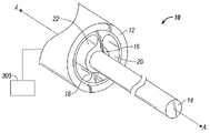
- FIG. 1Ais a front, perspective view of a centrally-disposed coaxial cable having an inner conductor held by two materials having different coefficient of thermal expansion values, in accordance with an embodiment of the present disclosure
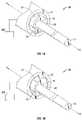
- FIG. 1Bis a front, perspective view of an off-center coaxial cable having an inner conductor held by two materials having different coefficient of thermal expansion values, in accordance with another embodiment of the present disclosure
- FIG. 1Cis a schematically-illustrated, cross-sectional view of the coaxial cable of FIG. 1A ;
- FIG. 1Dis a schematically-illustrated, cross-sectional view of the coaxial cable of FIG. 1B ;
- FIG. 2Ais front, perspective view of an off-centered coaxial cable having an inner conductor held by two materials having different coefficient of thermal expansion values, in accordance with another embodiment of the present disclosure
- FIG. 2Bis a front, perspective view of a centrally disposed coaxial cable having an inner conductor held by two materials having different coefficient of thermal expansion values, in accordance with another embodiment of the present disclosure
- FIG. 2Cis a schematically-illustrated, cross-sectional view of the coaxial cable of FIG. 2B ;
- FIG. 2Dis a schematically-illustrated, cross-sectional view of the coaxial cable of FIG. 2A ;
- FIG. 3is a schematically illustrated, cross-sectional view of a coaxial cable having an inner conductor held by one or more spacers being composed of one or more materials having different coefficient of thermal expansion values, in accordance with another embodiment of the present disclosure
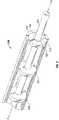
- FIG. 4Ais a front, perspective view of an off-centered coaxial cable having an inner conductor and a plurality of resistive heating elements in each of two or more materials having different coefficient of thermal expansion values, in accordance with another embodiment of the present disclosure
- FIG. 4Bis a front, perspective view of a centrally disposed coaxial cable having an inner conductor and a plurality of resistive heating elements in each of two or more materials having different coefficient of thermal expansion values, in accordance with another embodiment of the present disclosure
- FIG. 5Ais a schematically illustrated cross-sectional view of an off-centered coaxial cable having an inner conductor and a plurality of resistive heating elements in one material having one coefficient of thermal expansion value, in accordance with another embodiment of the present disclosure
- FIG. 5Bis a front, perspective view of a centrally disposed coaxial cable having an inner conductor and a plurality of resistive heating elements in one material having one coefficient of thermal expansion value, in accordance with another embodiment of the present disclosure
- FIG. 6is a front, perspective view of a coaxial cable having an inner conductor with a shape memory alloy, in accordance with another embodiment of the present disclosure.
- FIG. 7is a front, perspective view of a centrally-disposed coaxial cable having an inner conductor held by two materials having different coefficient of thermal expansion values with a fluid circulated therethrough for regulating the thermal expansion of the two materials in accordance with another embodiment of the present disclosure.
- the present disclosurepertains to a coaxial cable assembly and, in one embodiment, to a surgical device including the coaxial cable assembly.
- the surgical devicegenerally includes an ablative energy source and an ablative energy delivery device coupled to the ablative energy source.
- the ablative energy delivery deviceis configured to deliver ablative energy sufficiently strong enough to cause tissue ablation.
- the ablative energyis formed from electromagnetic energy in the microwave frequency range.
- Other applicationsare contemplated by the present disclosure, such as telecommunications or other suitable applications in which microwave antennas are utilized.
- the coaxial cable of the particular embodiments of the present disclosureare shown.
- the cablemay be of any suitable length, and the figures are not intended to limit the length of the cable to a specific length illustrated or any specific length. Instead, only a representative portion or section of cable is illustrated.
- the coaxial cable 10includes an outer conductor 12 , an inner conductor 14 , a first material 16 , a second material 18 , a first air gap 20 , and a second air gap 22 .
- the inner conductor 14is connected to an external power source 300 .
- the coaxial cable 10may be rigid, rigid-but shapeable or flexible.
- the coaxial cable 10may be chosen from commercially available standards and is generally designed with a characteristic impedance of 50 Ohms.
- one side of the coaxial cable 10may be coupled to a power supply 300 .
- the other side of the coaxial cable 10may be coupled to an antenna (not shown) in any suitable manner.
- the outer conductor 12is arranged to be generally concentric with respect to the inner conductor 14 .
- the concentric relationshipmay be configured to meet a particular purpose as explained in more detail below.
- Inner conductor 14is a central conductor used for transmitting signals and is typically held relative to the outer conductor 12 by first material 16 and second material 18 .
- first material 16holds the inner conductor 14
- second material 18supports the first material 16 without contacting the inner conductor 14 . In other words, only one material contacts the inner conductor 14 .
- the first material 16 and the second material 18define first and second air gaps 20 , 22 between the inner surface of the outer conductor 12 and the outer surface of the inner conductor 14 .
- the first air gap 20separates a first portion of the first material 16 and a first portion of the second material 18 .
- the second air gap 22separates a second portion of the first material 16 with a second portion of the second material 18 .
- the inner conductor 14has a significant effect on the coaxial cable's 10 properties, such as the cable's 10 impedance and attenuation characteristics.
- the impedance on the coaxial cable 10is related to the concentricity of the inner conductor 14 in relationship to the outer conductor 12 .
- a thermal increase to the coaxial cable 10is used to alter the alignment concentricity of the inner conductor 14 in a manner that would better match a change in tissue impedance.
- the coaxial cable 10 in the antenna(not shown) would start with an initial impedance match to a transmission line interface that would gradually taper along the length of the antenna toward a desired impedance with either the addition or the subtraction of heat.
- the tapercould be controlled thermally through additional features, such as a cooling jacket or cooling channels.
- FIGS. 1A and 1Cillustrate the inner conductor 14 in a centered position within the coaxial cable 10 .
- the inner conductor 14is moved to an off-centered position due to the thermal expansion of material 18 , as shown in FIGS. 1B and 1D .
- the alignment sensitivity of the cable 10may be selectively changed (e.g., automatically or manually) such that the impedance of the cable 10 better matches the tissue impedance.
- One or more materials with different coefficients of thermal expansionmay be utilized which mutually cooperate to tune the inner conductor 14 according to a desired setting, such as an ohmage setting.
- FIGS. 2A and 2Dshow an off-centered coaxial cable 110 and FIGS. 2B and 2C show a centrally disposed coaxial cable 110 having an inner conductor held by two materials having different coefficient of thermal expansion values.
- the coaxial cable 110includes an outer conductor 112 , an inner conductor 114 , a first material 116 and a second material 118 .
- the inner conductor 114is connected to an external power source 300 .
- the first material 116has a first coefficient of thermal expansion value and the second material 118 has a second coefficient of thermal expansion value, the first and second coefficient of thermal expansion values being different.
- the coefficient of thermal expansionis used in two ways: (1) as a volumetric thermal expansion coefficient and (2) as a linear thermal expansion coefficient.
- the first material 116expands at a first rate/volume and the second material 118 expands at a second rate/volume.
- Typical materials used in coaxial cablesinclude variations of PTFE, polyethylene (PE) blends and silica dioxides, however, nearly any thermo-set or thermoplastic with a low dielectric constant can be used in conjunction with another material of similar dielectric constant with a different coefficient of thermo-expansion.
- PEpolyethylene
- silica dioxidesnearly any thermo-set or thermoplastic with a low dielectric constant can be used in conjunction with another material of similar dielectric constant with a different coefficient of thermo-expansion.
- different polymer grades or blendsresult in varying material properties so determining the desired pair of materials would be a result of finding a matching mixture.
- the heat generated by the losses in the dielectric material in the cablecan also be utilized to heat material enough to generate the differential in thermal expansion between the varying materials.
- ABS Polymer ExtrudedABS Polymer Nylon Blend
- PEEK PolyketonePEKK Polyketone
- Nylon PTFE FilledPolycarbonate Extruded
- LDPEPolyethylene
- PolyimidePolyimide
- Silica AerogelSilica Aerogel
- the second material 118contracts due to the differing coefficient of thermal expansion values of the two materials 116 , 118 .
- the difference in expansion between the two materials 116 , 118would cause the inner conductor 114 to change alignment with the outer conductor 112 , e.g., move toward a centered position as illustrated in FIGS. 2B and 2C .
- the materials 116 , 118may be designed to selectively (e.g., either automatically or manually) align or misalign the inner conductor 114 relative to the outer conductor 112 for tuning and impedance matching purposes.
- the designcould be made to start with the inner conductor 114 concentrically centered relative to outer conductor 112 and then moved off center when the temperature changes.
- inner conductor 114may be normally off-center relative to outer conductor 112 , and as the temperature increases, the inner conductor 114 moves toward the concentric center of the coaxial cable 110 when one of the materials 116 , 118 is heated.
- the system described in regard to FIGS. 1A-2Bmay include an electrosurgical generator 300 having a microprocessor and sensor circuitry (not shown) that continually monitors tissue impedance and measures offset impedance.
- the sensor circuitrymay also continually monitor the position of the inner conductor 114 of a coaxial cable 110 with respect to a desired coaxial position (e.g., a center position).
- the monitormay be operably coupled to a mechanism (shape memory alloy, heat resistive element) as explained in more detail below) for regulating the thermal expansion of at least one of the first and second dielectric materials 116 , 118 to position the inner conductor 114 relative to the outer conductor 112 to change the impedance of the inner conductor 114 .
- the microprocessor or the circuitrymay also be configured to compare the inner conductor positioning to a predetermined center position. If the inner conductor is positioned above or below the predetermined center position, one or more materials 116 , 118 surrounding the inner conductor are heated or moved to re-position the inner conductor 114 to a desired position, and the microprocessor reports such findings to a user control or maintains this data for subsequent use.
- FIG. 3is a schematically illustrated cross-sectional view of a coaxial cable 210 having an inner conductor 214 held by one or more spacers 230 , 232 , 234 being composed of one or more materials having different coefficient of thermal expansion values.
- the coaxial cable 210includes an outer conductor 212 , an inner conductor 214 , a first material 216 , a second material 218 , a first spacer 230 , a second spacer 232 and a third spacer 234 .
- the inner conductor 214is connected to an external power source 300 .
- the first, second, and third spacers 230 , 232 , 234maintain a desired position (e.g., a center position) for the inner conductor 214 for at least a partial length of the coaxial cable 210 .
- Each of the spacers 230 , 232 , 234may have the same or a different width, and each may be composed of one material or two or more materials. Also, the material used for each spacer may be different.
- a first spacer 230may be composed of a first material 216 and a second material 218
- the second and third spacers 232 , 234may be composed of one material.
- FIG. 4Ais a schematically illustrated cross-sectional view of an off-centered coaxial cable 310 and FIG. 4B is a schematically illustrated cross-sectional view of a centrally disposed coaxial cable 310 having an inner conductor and a plurality of resistive heating elements in each of two or more materials having different coefficient of thermal expansion values.
- the coaxial cable 310includes an outer conductor 312 , an inner conductor 314 , a first material 316 , a second material 318 , first resistive heating elements 340 and second resistive heating elements 342 .
- FIG. 4Aillustrates the inner conductor 314 in an off-centered position within the coaxial cable 310 .
- the inner conductor 314moves to a centered position due to the thermal expansion of material 318 .
- the alignment sensitivity of the cable 310may be selectively changed (e.g., automatically or manually) such that the impedance of the cable 310 better matches the tissue impedance.
- One or more materialsmay be utilized to tune the inner conductor 314 according to a desired setting, such as an ohmage setting.
- a plurality of first resistive heating elements 340may be positioned in first material 316 and a plurality of second resistive heating elements 342 may be positioned in second material 318 .
- the first and second resistive heating elements 340 , 342convert electricity into heat. Electrical current running through the elements encounter resistance, thus resulting in heating of the element.
- Resistive heating elements 340 , 342may be made from Nichrome which has a relatively high resistance and does not break down or oxidize in air at useful temperature ranges.
- First and second resistive heating elements 340 , 342may also be positioned in parallel to the inner conductor 314 , at various lengths from the inner conductor 314 , and in various widths.
- each of the plurality of heating elements 340 , 342may be selectively controllable to position the inner conductor 314 relative to the outer conductor 312 and the plurality of heating elements 340 , 342 may be disposed in a concentric array relative to the inner conductor 314 .
- FIG. 5Ais a schematically illustrated cross-sectional view of an off-centered coaxial cable 410 and FIG. 5B is a schematically illustrated cross-sectional view of a centrally disposed coaxial cable 410 .
- the coaxial cable 410includes an outer conductor 412 , an inner conductor 414 , a dielectric material 416 , and one or more resistive heating elements 440 .
- only one dielectric material 416is used to surround the entire length of the inner conductor 414 .
- the dielectric material 416includes one or more resistive heating elements 440 in parallel to the inner conductor 414 along the length of the cable 410 . More particularly, the resistive heating elements 440 are positioned in parallel to the inner conductor 414 , at various lengths along the inner conductor 414 , and in various widths.
- FIG. 5Aillustrates the inner conductor 414 in an off-centered position within the dielectric material 416 .
- the inner conductor 414is moved to a desired position (e.g., a center position) due to the thermal expansion of dielectric material 416 and due to first resistive heating element 440 b being heated to expand the dielectric material 416 in a given direction.
- Any member or combination of heating elements 440 a - 440 emay be utilized to move the inner conductor 414 for tuning purposes.
- the alignment sensitivity of the cable 410may be selectively changed (e.g., automatically or manually) such that the impedance of the cable 410 better matches the tissue impedance.
- FIG. 6is a schematically illustrated cross-sectional view of a coaxial cable having an inner conductor with a shape memory alloy 550 in accordance with another embodiment of the present disclosure.
- the coaxial cable 510includes an outer conductor 512 , an inner conductor 514 , a dielectric material 516 and a shape memory alloy 550 .
- the shape memory alloy 550is, for example, positioned in proximity to the inner conductor 514 .
- One or more shape memory alloys 550may be positioned along the length of the coaxial cable 510 in predetermined distance from each other.
- SMAsShape memory alloys
- NitinolNitinol which can retain shape memories for two different physical configurations and changes shape as a function of temperature.
- SMAshave been developed based on copper, zinc and aluminum and have similar shape memory retaining features.
- SMAsundergo a crystalline phase transition upon applied temperature and/or stress variations.
- a particularly useful attribute of SMAsis that after it is deformed by temperature/stress, it can completely recover its original shape on being returned to the original temperature.
- the ability of an alloy to possess shape memoryis a result of the fact that the alloy undergoes a reversible transformation from an austenitic state to a martenistic state with a change in temperature/stress. This transformation is referred to as a thermoelastic martenistic transformation.
- thermoelastic martenistic transformationoccurs over a temperature range which varies with the composition of the alloy, itself, and the type of thermal-mechanical processing by which it was manufactured.
- the temperature at which a shape is “memorized” by an SMAis a function of the temperature at which the martensite and austenite crystals form in that particular alloy.
- Nitinol alloyscan be fabricated so that the shape memory effect will occur over a wide range of temperatures, e.g., ⁇ 270° to +100° Celsius.
- Many SMAsare also known to display stress-induced martenisite (SIM) which occurs when the alloy is deformed from its original austensitic state to a martensitic state by subjecting the alloy to a stress condition.
- SIMstress-induced martenisite
- SMA 550which is embedded within a material 516 having a certain coefficient of thermal expansion and which is located in a close proximity to the inner conductor 514 may move the inner conductor 514 back to its desired position (e.g., a center position) within the coaxial cable 510 .
- SMA 550can recover from large amounts of bending and torsional deformations, due to the application of heat, as well as small amounts of strain. Provided the deformations are within recoverable ranges, the process of deformation and shape recovery can be repeated millions of times.
- the SMA 550 located within the material 516can repeatedly move the inner conductor 514 back to a desired position (e.g., a centered position).
- the material 516may be designed to selectively (e.g., either automatically or manually) align or misalign the inner conductor 514 relative to the outer conductor 512 for tuning and impedance matching purposes.
- the embodiments of the present disclosureallow for improved antenna impedance matching for controlling tissue impedance of a microwave antenna during an ablation procedure via a thermally tuned coaxial cable.
- the embodimentsfurther include changing the impedance of the coaxial cable for allowing greater flexibility in designing microwave antennas.
- tissue impedancechanges, and thus, the antenna may deposit a greater amount of energy over the entire course of the ablation procedure.
- dielectric cores of varying thermal expansion valuesit is possible to force the eccentricity of the inner conductor of the coaxial cable on-line or off-line, thus effectively changing the coaxial cable's impedance value.
- FIGS. 1A-2Dillustrate two materials 16 , 18 within the spacing between the inner surface of the outer conductor 12 and the outer surface of the inner conductor 14 including two air spaces or gaps 20 , 22 .
- one skilled in the artmay use more than two materials within the spacing between the inner surface of the outer conductor 12 and the outer surface of the inner conductor 14 and more than two air gaps.
- one skilled in the artmay be motivated to use three or more materials, each with a different coefficient of thermal expansion value in a triangular configuration with three or more air gaps separating the materials.
- one skilled in the artmay be motivated to use two materials in a checkered pattern or any other type of intertwined pattern with one or more air gaps in order to center or off-center the inner conductor 14 of the coaxial cable 10 as needed to tune or match the tissue impedance.
- FIGS. 1A-6there may be one or more mechanisms that regulate the thermal expansion of at least one of the first and second dielectric materials 16 , 18 to position the inner conductor 14 relative to the outer conductor 12 to change the impedance of the inner conductor 14 .
- FIG. 7shows another embodiment according to the present disclosure wherein the coaxial cable 700 includes an outer conductor 712 arranged to be generally concentric with respect to the inner conductor 714 used for transmitting signals.
- Inner conductor 714is held relative to the outer conductor 712 by first material 716 and second material 718 only one of which contacts inner conductor 714 .
- First material 716 and the second material 718define first and second air gaps 720 and 722 , respectively, between the inner surface of the outer conductor 712 and the outer surface of the inner conductor 714 .
- a fluid 725is circulated within one or both the first and second dielectric materials 716 , 718 via conduits 727 and 729 defined respectively therein.
- the relative temperature of the fluid 725may be selectively controllable via circuitry controlled by the generator 300 to regulate thermal expansion of one or both the first and second dielectric materials 716 , 718 to position the inner conductor 714 relative to the outer conductor 712 to change the impedance of the inner conductor 714 .
- the fluid 725may optionally or alternatively be disposed between the first and second dielectric materials 716 , 718 and be controlled in a similar manner.
Landscapes
- Health & Medical Sciences (AREA)
- Surgery (AREA)
- Life Sciences & Earth Sciences (AREA)
- Medical Informatics (AREA)
- Animal Behavior & Ethology (AREA)
- Nuclear Medicine, Radiotherapy & Molecular Imaging (AREA)
- Electromagnetism (AREA)
- Engineering & Computer Science (AREA)
- Biomedical Technology (AREA)
- Heart & Thoracic Surgery (AREA)
- Physics & Mathematics (AREA)
- Molecular Biology (AREA)
- Otolaryngology (AREA)
- General Health & Medical Sciences (AREA)
- Public Health (AREA)
- Veterinary Medicine (AREA)
- Surgical Instruments (AREA)
- Communication Cables (AREA)
- Non-Reversible Transmitting Devices (AREA)
- Waveguide Aerials (AREA)
Abstract
Description
Claims (20)
Priority Applications (4)
| Application Number | Priority Date | Filing Date | Title |
|---|---|---|---|
| US12/351,633US7642451B2 (en) | 2008-01-23 | 2009-01-09 | Thermally tuned coaxial cable for microwave antennas |
| US12/651,762US8258399B2 (en) | 2008-01-23 | 2010-01-04 | Thermally tuned coaxial cable for microwave antennas |
| US13/598,141US8969722B2 (en) | 2008-01-23 | 2012-08-29 | Thermally tuned coaxial cable for microwave antennas |
| US14/604,418US9305682B2 (en) | 2008-01-23 | 2015-01-23 | Thermally tuned coaxial cable for microwave antennas |
Applications Claiming Priority (2)
| Application Number | Priority Date | Filing Date | Title |
|---|---|---|---|
| US2302908P | 2008-01-23 | 2008-01-23 | |
| US12/351,633US7642451B2 (en) | 2008-01-23 | 2009-01-09 | Thermally tuned coaxial cable for microwave antennas |
Related Child Applications (1)
| Application Number | Title | Priority Date | Filing Date |
|---|---|---|---|
| US12/651,762ContinuationUS8258399B2 (en) | 2008-01-23 | 2010-01-04 | Thermally tuned coaxial cable for microwave antennas |
Publications (2)
| Publication Number | Publication Date |
|---|---|
| US20090183895A1 US20090183895A1 (en) | 2009-07-23 |
| US7642451B2true US7642451B2 (en) | 2010-01-05 |
Family
ID=40758696
Family Applications (4)
| Application Number | Title | Priority Date | Filing Date |
|---|---|---|---|
| US12/351,633ActiveUS7642451B2 (en) | 2008-01-23 | 2009-01-09 | Thermally tuned coaxial cable for microwave antennas |
| US12/651,762Expired - Fee RelatedUS8258399B2 (en) | 2008-01-23 | 2010-01-04 | Thermally tuned coaxial cable for microwave antennas |
| US13/598,141Expired - Fee RelatedUS8969722B2 (en) | 2008-01-23 | 2012-08-29 | Thermally tuned coaxial cable for microwave antennas |
| US14/604,418Expired - Fee RelatedUS9305682B2 (en) | 2008-01-23 | 2015-01-23 | Thermally tuned coaxial cable for microwave antennas |
Family Applications After (3)
| Application Number | Title | Priority Date | Filing Date |
|---|---|---|---|
| US12/651,762Expired - Fee RelatedUS8258399B2 (en) | 2008-01-23 | 2010-01-04 | Thermally tuned coaxial cable for microwave antennas |
| US13/598,141Expired - Fee RelatedUS8969722B2 (en) | 2008-01-23 | 2012-08-29 | Thermally tuned coaxial cable for microwave antennas |
| US14/604,418Expired - Fee RelatedUS9305682B2 (en) | 2008-01-23 | 2015-01-23 | Thermally tuned coaxial cable for microwave antennas |
Country Status (3)
| Country | Link |
|---|---|
| US (4) | US7642451B2 (en) |
| EP (2) | EP3002764A3 (en) |
| JP (1) | JP5460061B2 (en) |
Cited By (36)
| Publication number | Priority date | Publication date | Assignee | Title |
|---|---|---|---|---|
| US20090082762A1 (en)* | 2007-09-20 | 2009-03-26 | Ormsby Theodore C | Radio frequency energy transmission device for the ablation of biological tissues |
| US20110034919A1 (en)* | 2009-08-06 | 2011-02-10 | Vivant Medical, Inc. | Vented Positioner and Spacer and Method of Use |
| US20110077634A1 (en)* | 2009-09-28 | 2011-03-31 | Vivant Medical, Inc. | Microwave Surface Ablation Using Conical Probe |
| US20110295246A1 (en)* | 2010-05-26 | 2011-12-01 | Vivant Medical, Inc. | System and Method for Chemically Cooling an Ablation Antenna |
| US8328801B2 (en) | 2009-08-17 | 2012-12-11 | Vivant Medical, Inc. | Surface ablation antenna with dielectric loading |
| USD673685S1 (en) | 2010-09-08 | 2013-01-01 | Vivant Medical, Inc. | Microwave device spacer and positioner with arcuate slot |
| US8355803B2 (en) | 2009-09-16 | 2013-01-15 | Vivant Medical, Inc. | Perfused core dielectrically loaded dipole microwave antenna probe |
| US8608731B2 (en) | 2009-02-20 | 2013-12-17 | Covidien Lp | Leaky-wave antennas for medical applications |
| US8667674B2 (en) | 2008-06-09 | 2014-03-11 | Covidien Lp | Surface ablation process with electrode cooling methods |
| US8679108B2 (en) | 2009-02-20 | 2014-03-25 | Covidien Lp | Leaky-wave antennas for medical applications |
| US8690869B2 (en) | 2009-06-02 | 2014-04-08 | Covidien Lp | Electrosurgical devices with directional radiation pattern |
| US8740893B2 (en) | 2010-06-30 | 2014-06-03 | Covidien Lp | Adjustable tuning of a dielectrically loaded loop antenna |
| US8894640B2 (en) | 2009-09-24 | 2014-11-25 | Covidien Lp | Optical detection of interrupted fluid flow to ablation probe |
| US8894641B2 (en) | 2009-10-27 | 2014-11-25 | Covidien Lp | System and method for monitoring ablation size |
| US8945144B2 (en) | 2010-09-08 | 2015-02-03 | Covidien Lp | Microwave spacers and method of use |
| US8968291B2 (en) | 2007-11-16 | 2015-03-03 | Covidien Lp | Dynamically matched microwave antenna for tissue ablation |
| US8968289B2 (en) | 2010-10-22 | 2015-03-03 | Covidien Lp | Microwave spacers and methods of use |
| US9017328B2 (en) | 2008-01-29 | 2015-04-28 | Covidien Lp | Polyp encapsulation system and method |
| US9192437B2 (en) | 2009-05-27 | 2015-11-24 | Covidien Lp | Narrow gauge high strength choked wet tip microwave ablation antenna |
| US9200234B1 (en) | 2009-10-21 | 2015-12-01 | Encore Wire Corporation | System, composition and method of application of same for reducing the coefficient of friction and required pulling force during installation of wire or cable |
| US9254172B2 (en) | 2008-09-03 | 2016-02-09 | Covidien Lp | Shielding for an isolation apparatus used in a microwave generator |
| US9352371B1 (en) | 2012-02-13 | 2016-05-31 | Encore Wire Corporation | Method of manufacture of electrical wire and cable having a reduced coefficient of friction and required pulling force |
| US20170098493A1 (en)* | 2015-10-06 | 2017-04-06 | Commscope Technologies Llc | Coaxial cable with dielectric layer having sealed segments and method of making same |
| US9681916B2 (en) | 2012-01-06 | 2017-06-20 | Covidien Lp | System and method for treating tissue using an expandable antenna |
| US9693823B2 (en) | 2012-01-06 | 2017-07-04 | Covidien Lp | System and method for treating tissue using an expandable antenna |
| US20170346241A1 (en)* | 2016-05-25 | 2017-11-30 | Delphi International Operations Luxembourg S.A.R.L. | Cable attachment device and connection assembly for measuring cable temperature |
| US9833286B2 (en) | 2009-05-06 | 2017-12-05 | Covidien Lp | Power-stage antenna integrated system with high-strength shaft |
| US9867670B2 (en) | 2009-04-01 | 2018-01-16 | Covidien Lp | Microwave ablation system and user-controlled ablation size and method of use |
| US9949794B2 (en) | 2008-03-27 | 2018-04-24 | Covidien Lp | Microwave ablation devices including expandable antennas and methods of use |
| US10022186B2 (en) | 2008-08-28 | 2018-07-17 | Covidien Lp | Microwave antenna with cooled handle |
| US10056742B1 (en) | 2013-03-15 | 2018-08-21 | Encore Wire Corporation | System, method and apparatus for spray-on application of a wire pulling lubricant |
| US10321962B2 (en) | 2007-11-01 | 2019-06-18 | Covidien Lp | Method for volume determination and geometric reconstruction |
| US20210020327A1 (en)* | 2019-07-18 | 2021-01-21 | Nokia Shanghai Bell Co., Ltd. | Dielectric structure, a method of manufacturing thereof and a fire rated radio frequency cable having the dielectric structure |
| US11328843B1 (en) | 2012-09-10 | 2022-05-10 | Encore Wire Corporation | Method of manufacture of electrical wire and cable having a reduced coefficient of friction and required pulling force |
| US20230163493A1 (en)* | 2020-04-21 | 2023-05-25 | Totoku Electric Co., Ltd. | Coaxial flat cable |
| US12318133B2 (en) | 2008-01-23 | 2025-06-03 | Covidien Lp | Choked microwave antenna |
Families Citing this family (24)
| Publication number | Priority date | Publication date | Assignee | Title |
|---|---|---|---|---|
| US7642451B2 (en) | 2008-01-23 | 2010-01-05 | Vivant Medical, Inc. | Thermally tuned coaxial cable for microwave antennas |
| US8221418B2 (en) | 2008-02-07 | 2012-07-17 | Tyco Healthcare Group Lp | Endoscopic instrument for tissue identification |
| US8211098B2 (en)* | 2008-08-25 | 2012-07-03 | Vivant Medical, Inc. | Microwave antenna assembly having a dielectric body portion with radial partitions of dielectric material |
| US8246615B2 (en) | 2009-05-19 | 2012-08-21 | Vivant Medical, Inc. | Tissue impedance measurement using a secondary frequency |
| USD634010S1 (en) | 2009-08-05 | 2011-03-08 | Vivant Medical, Inc. | Medical device indicator guide |
| DE102010001273A1 (en)* | 2009-12-30 | 2011-07-07 | Endress + Hauser GmbH + Co. KG, 79689 | Device with coaxial construction |
| US8575490B2 (en)* | 2010-01-19 | 2013-11-05 | Apple Inc. | Spacer for use in a flat cable |
| US9568367B2 (en) | 2010-05-30 | 2017-02-14 | Technion Research And Development Foundation Ltd. | Sensing device having a thermal antenna and a method for sensing electromagnetic radiation |
| US8992413B2 (en) | 2011-05-31 | 2015-03-31 | Covidien Lp | Modified wet tip antenna design |
| US9016367B2 (en)* | 2012-07-19 | 2015-04-28 | Harris Corporation | RF antenna assembly including dual-wall conductor and related methods |
| US9458708B2 (en)* | 2012-08-07 | 2016-10-04 | Harris Corporation | RF coaxial transmission line for a wellbore including dual-wall outer conductor and related methods |
| US9322256B2 (en) | 2013-03-14 | 2016-04-26 | Harris Corporation | RF antenna assembly with dielectric isolator and related methods |
| US9377553B2 (en) | 2013-09-12 | 2016-06-28 | Harris Corporation | Rigid coaxial transmission line sections joined by connectors for use in a subterranean wellbore |
| US9376899B2 (en)* | 2013-09-24 | 2016-06-28 | Harris Corporation | RF antenna assembly with spacer and sheath and related methods |
| CN104575740A (en)* | 2013-10-13 | 2015-04-29 | 宁夏海洋线缆有限公司 | Multifunctional cable |
| GB201323171D0 (en)* | 2013-12-31 | 2014-02-12 | Creo Medical Ltd | Electrosurgical apparatus and device |
| CN104086716A (en)* | 2014-06-27 | 2014-10-08 | 绿宝电缆(集团)有限公司 | High-temperature-resistant modified polyethylene sheath material for special cables |
| GB2545179B (en) | 2015-12-07 | 2020-09-09 | Creo Medical Ltd | Electrosurgical instrument |
| GB2551339B (en)* | 2016-06-13 | 2021-12-08 | Creo Medical Ltd | Electrosurgical device with integrated microwave source |
| GB2559595B (en) | 2017-02-10 | 2021-09-01 | Creo Medical Ltd | Electrosurgical apparatus and electrosurgical instrument |
| US11473431B2 (en)* | 2019-03-12 | 2022-10-18 | Raytheon Technologies Corporation | Energy dissipating damper |
| CN113381217B (en)* | 2020-02-25 | 2023-08-04 | 泰科电子(上海)有限公司 | Connector and cable |
| JP6977198B1 (en)* | 2021-10-05 | 2021-12-08 | 東京特殊電線株式会社 | coaxial cable |
| CN116505220A (en)* | 2023-05-18 | 2023-07-28 | 苏州麦田微系统技术有限公司 | Shape memory polymer medium reconfigurable micro-coaxial structure and preparation method |
Citations (90)
| Publication number | Priority date | Publication date | Assignee | Title |
|---|---|---|---|---|
| SU166452A1 (en) | В. А. Костров , Л. В. Смирнов | STOMATOLOGICAL DIATHERMOKOAGULATOR | ||
| DE390937C (en) | 1922-10-13 | 1924-03-03 | Adolf Erb | Device for internal heating of furnace furnaces for hardening, tempering, annealing, quenching and melting |
| US2599857A (en)* | 1946-01-18 | 1952-06-10 | Telegraph Constr & Main Co | Method of manufacture of insulation for coaxial cables |
| DE1099658B (en) | 1959-04-29 | 1961-02-16 | Siemens Reiniger Werke Ag | Automatic switch-on device for high-frequency surgical devices |
| FR1275415A (en) | 1960-09-26 | 1961-11-10 | Device for detecting disturbances for electrical installations, in particular electrosurgery | |
| DE1139927B (en) | 1961-01-03 | 1962-11-22 | Friedrich Laber | High-frequency surgical device |
| DE1149832B (en) | 1961-02-25 | 1963-06-06 | Siemens Reiniger Werke Ag | High frequency surgical apparatus |
| FR1347865A (en) | 1962-11-22 | 1964-01-04 | Improvements to diathermo-coagulation devices | |
| DE1439302A1 (en) | 1963-10-26 | 1969-01-23 | Siemens Ag | High-frequency surgical device |
| US3761332A (en)* | 1969-09-29 | 1973-09-25 | Gen Cable Corp | Watertight disc coaxial cable |
| SU401367A1 (en) | 1971-10-05 | 1973-10-12 | Тернопольский государственный медицинский институт | BIAKTIVNYE ELECTRO SURGICAL INSTRUMENT |
| FR2235669A1 (en) | 1973-07-07 | 1975-01-31 | Lunacek Boris | Gynaecological sterilisation instrument - has hollow electrode protruding from the end of a curved ended tube |
| DE2439587A1 (en) | 1973-08-23 | 1975-02-27 | Matburn Holdings Ltd | ELECTROSURGICAL DEVICE |
| DE2455174A1 (en) | 1973-11-21 | 1975-05-22 | Termiflex Corp | INPUT / OUTPUT DEVICE FOR DATA EXCHANGE WITH DATA PROCESSING DEVICES |
| DE2407559A1 (en) | 1974-02-16 | 1975-08-28 | Dornier System Gmbh | Tissue heat treatment probe - has water cooling system which ensures heat development only in treated tissues |
| DE2415263A1 (en) | 1974-03-29 | 1975-10-02 | Aesculap Werke Ag | Surgical H.F. coagulation probe has electrode tongs - with exposed ends of insulated conductors forming tong-jaws |
| DE2429021A1 (en) | 1974-06-18 | 1976-01-08 | Erbe Elektromedizin | Remote control for HF surgical instruments - uses cable with two conductors at most |
| FR2276027A1 (en) | 1974-06-25 | 1976-01-23 | Medical Plastics Inc | Plate electrode with connector - is clamped between connector jaws held by releasable locking device |
| DE2460481A1 (en) | 1974-12-20 | 1976-06-24 | Delma Elektro Med App | Electrode grip for remote HF surgical instrument switching - has shaped insulated piece with contact ring of sterilizable (silicon) rubber |
| DE2602517A1 (en) | 1975-01-23 | 1976-07-29 | Dentsply Int Inc | ELECTROSURGICAL DEVICE |
| DE2504280A1 (en) | 1975-02-01 | 1976-08-05 | Hans Heinrich Prof Dr Meinke | DEVICE FOR ELECTRIC TISSUE CUTTING IN SURGERY |
| FR2313708A1 (en) | 1975-06-02 | 1976-12-31 | Sybron Corp | Electro surgical instrument impulse control circuit - has potentiometer between patient electrodes and threshold switch for excessive voltage |
| DE2627679A1 (en) | 1975-06-26 | 1977-01-13 | Marcel Lamidey | HEMATISTIC HIGH FREQUENCY EXTRACTOR FORCEPS |
| US4011118A (en)* | 1974-05-21 | 1977-03-08 | U.S. Philips Corporation | Method of manufacturing a coaxial cable, and coaxial cable made by this method |
| DE2540968A1 (en) | 1975-09-13 | 1977-03-17 | Erbe Elektromedizin | Circuit for bipolar coagulation tweezers - permits preparation of tissues prior to coagulation |
| US4018977A (en)* | 1975-08-04 | 1977-04-19 | Amp Incorporated | High voltage cable with air dielectric |
| DE2820908A1 (en) | 1977-05-16 | 1978-11-23 | Joseph Skovajsa | DEVICE FOR THE LOCAL TREATMENT OF A PATIENT IN PARTICULAR FOR ACUPUNCTURE OR AURICULAR THERAPY |
| DE2803275A1 (en) | 1978-01-26 | 1979-08-02 | Aesculap Werke Ag | HF surgical appts. with active treatment and patient electrodes - has sensor switching generator to small voltage when hand-operated switch is closed |
| DE2823291A1 (en) | 1978-05-27 | 1979-11-29 | Rainer Ing Grad Koch | Coagulation instrument automatic HF switching circuit - has first lead to potentiometer and second to transistor base |
| SU727201A2 (en) | 1977-11-02 | 1980-04-15 | Киевский Научно-Исследовательский Институт Нейрохирургии | Electric surgical apparatus |
| DE2946728A1 (en) | 1979-11-20 | 1981-05-27 | Erbe Elektromedizin GmbH & Co KG, 7400 Tübingen | HF surgical appts. for use with endoscope - provides cutting or coagulation current at preset intervals and of selected duration |
| DE3143421A1 (en) | 1980-11-04 | 1982-05-27 | The Agency of Industrial Science and Technology, Tokyo | Laser scalpel |
| DE3045996A1 (en) | 1980-12-05 | 1982-07-08 | Medic Eschmann Handelsgesellschaft für medizinische Instrumente mbH, 2000 Hamburg | Electro-surgical scalpel instrument - has power supply remotely controlled by surgeon |
| FR2502935A1 (en) | 1981-03-31 | 1982-10-08 | Dolley Roger | Diathermic knife for coagulating tissues - has monitoring current added to HF coagulating current in order to control end of operation as function or resistance of coagulating tissues |
| DE3120102A1 (en) | 1981-05-20 | 1982-12-09 | F.L. Fischer GmbH & Co, 7800 Freiburg | ARRANGEMENT FOR HIGH-FREQUENCY COAGULATION OF EGG WHITE FOR SURGICAL PURPOSES |
| FR2517953A1 (en) | 1981-12-10 | 1983-06-17 | Alvar Electronic | Diaphanometer for optical examination of breast tissue structure - measures tissue transparency using two plates and optical fibre bundle cooperating with photoelectric cells |
| FR2573301A1 (en) | 1984-11-16 | 1986-05-23 | Lamidey Gilles | Surgical forceps and its control and monitoring apparatus |
| DE3510586A1 (en) | 1985-03-23 | 1986-10-02 | Erbe Elektromedizin GmbH, 7400 Tübingen | Control device for a high-frequency surgical instrument |
| DE3604823A1 (en) | 1986-02-15 | 1987-08-27 | Flachenecker Gerhard | HIGH FREQUENCY GENERATOR WITH AUTOMATIC PERFORMANCE CONTROL FOR HIGH FREQUENCY SURGERY |
| EP0246350A1 (en) | 1986-05-23 | 1987-11-25 | Erbe Elektromedizin GmbH. | Coagulation electrode |
| DE8712328U1 (en) | 1987-09-11 | 1988-02-18 | Jakoubek, Franz, 7201 Emmingen-Liptingen | Endoscopy forceps |
| DE3711511C1 (en) | 1987-04-04 | 1988-06-30 | Hartmann & Braun Ag | Method for determining gas concentrations in a gas mixture and sensor for measuring thermal conductivity |
| DE3904558A1 (en) | 1989-02-15 | 1990-08-23 | Flachenecker Gerhard | Radio-frequency generator with automatic power control for radio-frequency surgery |
| DE3942998A1 (en) | 1989-12-27 | 1991-07-04 | Delma Elektro Med App | Electro-surgical HF instrument for contact coagulation - has monitoring circuit evaluating HF voltage at electrodes and delivering switch=off signal |
| EP0481685A1 (en) | 1990-10-15 | 1992-04-22 | Cook Incorporated | Medical device for localizing a lesion |
| EP0521264A2 (en) | 1991-07-03 | 1993-01-07 | W.L. Gore & Associates GmbH | Antenna device with feed |
| JPH055106A (en) | 1990-07-31 | 1993-01-14 | Matsushita Electric Works Ltd | Production of alloy sintered body |
| JPH0540112A (en) | 1991-02-08 | 1993-02-19 | Tokico Ltd | Sample liquid component analyzer |
| DE4238263A1 (en) | 1991-11-15 | 1993-05-19 | Minnesota Mining & Mfg | Adhesive comprising hydrogel and crosslinked polyvinyl:lactam - is used in electrodes for biomedical application providing low impedance and good mechanical properties when water and/or moisture is absorbed from skin |
| EP0541930A1 (en) | 1991-10-17 | 1993-05-19 | Acufex Microsurgical Inc. | Transmission link for use in surgical instruments |
| EP0556705A1 (en) | 1992-02-20 | 1993-08-25 | DELMA ELEKTRO-UND MEDIZINISCHE APPARATEBAU GESELLSCHAFT mbH | High frequency surgery device |
| EP0558429A1 (en) | 1992-02-26 | 1993-09-01 | PECHINEY RECHERCHE (Groupement d'Intérêt Economique géré par l'ordonnance no. 67-821 du 23 Septembre 1967) | Method of simultaneous measuring of electrical resistivety and thermal conductivity |
| US5262593A (en)* | 1991-03-09 | 1993-11-16 | Alcatel N.V. | Coaxial electrical high-frequency cable |
| EP0572131A1 (en) | 1992-05-21 | 1993-12-01 | Everest Medical Corporation | Surgical scissors with bipolar coagulation feature |
| DE4303882A1 (en) | 1993-02-10 | 1994-08-18 | Kernforschungsz Karlsruhe | Combined instrument for separating and coagulating in minimally invasive surgery |
| US5369251A (en) | 1992-09-14 | 1994-11-29 | Kdc Technology Corp. | Microwave interstitial hyperthermia probe |
| JPH06343644A (en) | 1993-05-04 | 1994-12-20 | Gyrus Medical Ltd | Surgical peritoneoscope equipment |
| DE4339049A1 (en) | 1993-11-16 | 1995-05-18 | Erbe Elektromedizin | Surgical system and instruments configuration device |
| JPH07265328A (en) | 1993-11-01 | 1995-10-17 | Gyrus Medical Ltd | Electrode assembly for electric surgery device and electric surgery device using it |
| JPH0856955A (en) | 1994-06-29 | 1996-03-05 | Gyrus Medical Ltd | Electric surgical apparatus |
| JPH08252263A (en) | 1994-12-21 | 1996-10-01 | Gyrus Medical Ltd | Electronic surgical incision instrument and electronic surgical incision device using the same |
| DE29616210U1 (en) | 1996-09-18 | 1996-11-14 | Olympus Winter & Ibe Gmbh, 22045 Hamburg | Handle for surgical instruments |
| JPH0910223A (en) | 1995-06-23 | 1997-01-14 | Gyrus Medical Ltd | Generator and system for electric operation |
| DE19608716C1 (en) | 1996-03-06 | 1997-04-17 | Aesculap Ag | Bipolar surgical holding instrument |
| EP0836868A2 (en) | 1996-10-18 | 1998-04-22 | Gebr. Berchtold GmbH & Co. | High frequency surgical apparatus and method for operating same |
| DE19751106A1 (en) | 1996-11-27 | 1998-05-28 | Eastman Kodak Co | Laser printer with array of laser diodes |
| US5810803A (en) | 1996-10-16 | 1998-09-22 | Fidus Medical Technology Corporation | Conformal positioning assembly for microwave ablation catheter |
| DE19717411A1 (en) | 1997-04-25 | 1998-11-05 | Aesculap Ag & Co Kg | Monitoring of thermal loading of patient tissue in contact region of neutral electrode of HF treatment unit |
| DE19751108A1 (en) | 1997-11-18 | 1999-05-20 | Beger Frank Michael Dipl Desig | Electrosurgical operation tool, especially for diathermy |
| DE19801173C1 (en) | 1998-01-15 | 1999-07-15 | Kendall Med Erzeugnisse Gmbh | Clamp connector for film electrodes |
| JPH11244298A (en) | 1997-12-19 | 1999-09-14 | Gyrus Medical Ltd | Electric surgical instrument |
| US6026331A (en) | 1993-07-27 | 2000-02-15 | Microsulis Limited | Treatment apparatus |
| DE19848540A1 (en) | 1998-10-21 | 2000-05-25 | Reinhard Kalfhaus | Circuit layout and method for operating a single- or multiphase current inverter connects an AC voltage output to a primary winding and current and a working resistance to a transformer's secondary winding and current. |
| JP2000342599A (en) | 1999-05-21 | 2000-12-12 | Gyrus Medical Ltd | Generator for electrosurgical operation, electrosurgical operation system, method for operating this system and method for performing amputation and resection of tissue by electrosurgical operation |
| JP2000350732A (en) | 1999-05-21 | 2000-12-19 | Gyrus Medical Ltd | Electrosurgical system, generator for electrosurgery, and method for cutting or excising tissue by electrosurgery |
| JP2001008944A (en) | 1999-05-28 | 2001-01-16 | Gyrus Medical Ltd | Electric surgical signal generator and electric surgical system |
| JP2001029356A (en) | 1999-06-11 | 2001-02-06 | Gyrus Medical Ltd | Electric and surgical signal generator |
| JP2001128990A (en) | 1999-05-28 | 2001-05-15 | Gyrus Medical Ltd | Electro surgical instrument and electrosurgical tool converter |
| US6287302B1 (en) | 1999-06-14 | 2001-09-11 | Fidus Medical Technology Corporation | End-firing microwave ablation instrument with horn reflection device |
| EP1159926A2 (en) | 2000-06-03 | 2001-12-05 | Aesculap Ag | Scissor- or forceps-like surgical instrument |
| US6346671B1 (en)* | 1997-08-29 | 2002-02-12 | Alcatel | Coaxial high-frequency cable |
| DE10224154A1 (en) | 2002-05-27 | 2003-12-18 | Celon Ag Medical Instruments | Application device for electrosurgical device for body tissue removal via of HF current has electrode subset selected from active electrode set in dependence on measured impedance of body tissue |
| DE10328514B3 (en) | 2003-06-20 | 2005-03-03 | Aesculap Ag & Co. Kg | Endoscopic surgical scissor instrument has internal pushrod terminating at distal end in transverse cylindrical head |
| US6878147B2 (en) | 2001-11-02 | 2005-04-12 | Vivant Medical, Inc. | High-strength microwave antenna assemblies |
| FR2862813A1 (en) | 2003-11-20 | 2005-05-27 | Pellenc Sa | METHOD FOR BALANCED LOADING OF LITHIUM-ION OR POLYMER LITHIUM BATTERY |
| FR2864439A1 (en) | 2003-12-30 | 2005-07-01 | Image Guided Therapy | Tumor treating device for use by surgeon, has generator applying voltage to each of active electrodes in manner independent from other electrodes and having sinusoidal voltage generation unit adjusting amplitude and phase of voltage |
| DE102004022206A1 (en) | 2004-05-04 | 2005-12-01 | Bundesrepublik Deutschland, vertr. d. d. Bundesministerium für Wirtschaft und Arbeit, dieses vertr. d. d. Präsidenten der Physikalisch-Technischen Bundesanstalt | Sensor for measuring thermal conductivity comprises a strip composed of two parallel sections, and two outer heating strips |
| DE202005015147U1 (en) | 2005-09-26 | 2006-02-09 | Health & Life Co., Ltd., Chung-Ho | Biosensor test strip with identifying function for biological measuring instruments has functioning electrode and counter electrode, identification zones with coating of electrically conductive material and reaction zone |
| US7194297B2 (en) | 2001-11-13 | 2007-03-20 | Boston Scientific Scimed, Inc. | Impedance-matching apparatus and construction for intravascular device |
| US7244254B2 (en) | 2004-04-29 | 2007-07-17 | Micrablate | Air-core microwave ablation antennas |
Family Cites Families (62)
| Publication number | Priority date | Publication date | Assignee | Title |
|---|---|---|---|---|
| JPS54786A (en)* | 1977-06-06 | 1979-01-06 | Nippon Telegr & Teleph Corp <Ntt> | Seabed coaxial cable |
| USD263020S (en) | 1980-01-22 | 1982-02-16 | Rau Iii David M | Retractable knife |
| USD266842S (en) | 1980-06-27 | 1982-11-09 | Villers Mark W | Phonograph record spacer |
| USD278306S (en) | 1980-06-30 | 1985-04-09 | Mcintosh Lois A | Microwave oven rack |
| JPS60211451A (en) | 1984-04-05 | 1985-10-23 | Asahi Chem Ind Co Ltd | Photosensitive elastomer composition |
| USD295893S (en) | 1985-09-25 | 1988-05-24 | Acme United Corporation | Disposable surgical clamp |
| USD295894S (en) | 1985-09-26 | 1988-05-24 | Acme United Corporation | Disposable surgical scissors |
| JPH055106Y2 (en) | 1986-02-28 | 1993-02-09 | ||
| JPH0540112Y2 (en) | 1987-03-03 | 1993-10-12 | ||
| USD354218S (en) | 1992-10-01 | 1995-01-10 | Fiberslab Pty Limited | Spacer for use in concrete construction |
| US5364392A (en)* | 1993-05-14 | 1994-11-15 | Fidus Medical Technology Corporation | Microwave ablation catheter system with impedance matching tuner and method |
| FR2711066B1 (en) | 1993-10-15 | 1995-12-01 | Sadis Bruker Spectrospin | Antenna for heating fabrics by microwave and probe comprising one or more of these antennas. |
| CN1079269C (en) | 1993-11-17 | 2002-02-20 | 刘中一 | Multi-frequency micro-wave therapeutic instrument |
| JP3500228B2 (en) | 1995-06-21 | 2004-02-23 | オリンパス株式会社 | Endoscope treatment instrument insertion / extraction device |
| DE59712260D1 (en) | 1997-06-06 | 2005-05-12 | Endress & Hauser Gmbh & Co Kg | Microwave level gauge |
| US6812401B2 (en) | 1998-10-05 | 2004-11-02 | Temp-Flex Cable, Inc. | Ultra-small high-speed coaxial cable with dual filament insulator |
| USD449886S1 (en) | 1998-10-23 | 2001-10-30 | Sherwood Services Ag | Forceps with disposable electrode |
| USD424694S (en) | 1998-10-23 | 2000-05-09 | Sherwood Services Ag | Forceps |
| USD425201S (en) | 1998-10-23 | 2000-05-16 | Sherwood Services Ag | Disposable electrode assembly |
| EP2206475A3 (en) | 1998-12-18 | 2010-11-17 | Celon AG Medical Instruments | Electrode assembly for a surgical instrument for carrying out an electrothermal coagulation of tissue |
| US6288328B1 (en) | 1999-03-19 | 2001-09-11 | Avaya Technology Corp. | Coaxial cable having effective insulated conductor rotation |
| USD424693S (en) | 1999-04-08 | 2000-05-09 | Pruter Rick L | Needle guide for attachment to an ultrasound transducer probe |
| JP2001003776A (en) | 1999-06-22 | 2001-01-09 | Mitsubishi Electric Corp | Automatic transmission control device |
| JP2001037775A (en) | 1999-07-26 | 2001-02-13 | Olympus Optical Co Ltd | Treatment device |
| JP2001231870A (en) | 2000-02-23 | 2001-08-28 | Olympus Optical Co Ltd | Moisturizing treatment apparatus |
| FR2810822B1 (en)* | 2000-06-23 | 2004-09-17 | France Telecom | SECURE BIOMETRIC AUTHENTICATION / IDENTIFICATION METHOD, INPUT MODULE AND BIOMETRIC DATA VERIFICATION MODULE FOR CARRYING OUT THE METHOD |
| USD457959S1 (en) | 2001-04-06 | 2002-05-28 | Sherwood Services Ag | Vessel sealer |
| USD457958S1 (en) | 2001-04-06 | 2002-05-28 | Sherwood Services Ag | Vessel sealer and divider |
| US6849799B2 (en) | 2002-10-22 | 2005-02-01 | 3M Innovative Properties Company | High propagation speed coaxial and twinaxial cable |
| USD487039S1 (en) | 2002-11-27 | 2004-02-24 | Robert Bosch Corporation | Spacer |
| DE10310765A1 (en) | 2003-03-12 | 2004-09-30 | Dornier Medtech Systems Gmbh | Medical thermotherapy instrument, e.g. for treatment of benign prostatic hypertrophy (BPH), has an antenna that can be set to radiate at least two different frequency microwave signals |
| JP4228756B2 (en)* | 2003-04-10 | 2009-02-25 | 株式会社村田製作所 | Coaxial cable and antenna device |
| USD496997S1 (en) | 2003-05-15 | 2004-10-05 | Sherwood Services Ag | Vessel sealer and divider |
| USD499181S1 (en) | 2003-05-15 | 2004-11-30 | Sherwood Services Ag | Handle for a vessel sealer and divider |
| US6712644B1 (en) | 2003-05-28 | 2004-03-30 | Spx Corporation | Coaxial line section assembly and method with VSWR compensation |
| US6816039B1 (en)* | 2003-07-10 | 2004-11-09 | Agilent Technologies, Inc. | Coaxial split-bead glass-to-metal seal for high frequency transmission line |
| US7311703B2 (en) | 2003-07-18 | 2007-12-25 | Vivant Medical, Inc. | Devices and methods for cooling microwave antennas |
| US6956164B2 (en) | 2003-12-23 | 2005-10-18 | Spx Corporation | Inner conductor supports for rigid coaxial transmission lines |
| USD541938S1 (en) | 2004-04-09 | 2007-05-01 | Sherwood Services Ag | Open vessel sealer with mechanical cutter |
| US7101369B2 (en)* | 2004-04-29 | 2006-09-05 | Wisconsin Alumni Research Foundation | Triaxial antenna for microwave tissue ablation |
| US8805480B2 (en) | 2004-05-26 | 2014-08-12 | Medical Device Innovations Limited | Tissue detection and ablation apparatus and apparatus and method for actuating a tuner |
| USD533942S1 (en) | 2004-06-30 | 2006-12-19 | Sherwood Services Ag | Open vessel sealer with mechanical cutter |
| USD535027S1 (en) | 2004-10-06 | 2007-01-09 | Sherwood Services Ag | Low profile vessel sealing and cutting mechanism |
| USD541418S1 (en) | 2004-10-06 | 2007-04-24 | Sherwood Services Ag | Lung sealing device |
| USD525361S1 (en) | 2004-10-06 | 2006-07-18 | Sherwood Services Ag | Hemostat style elongated dissecting and dividing instrument |
| USD531311S1 (en) | 2004-10-06 | 2006-10-31 | Sherwood Services Ag | Pistol grip style elongated dissecting and dividing instrument |
| USD564662S1 (en) | 2004-10-13 | 2008-03-18 | Sherwood Services Ag | Hourglass-shaped knife for electrosurgical forceps |
| USD576932S1 (en) | 2005-03-01 | 2008-09-16 | Robert Bosch Gmbh | Spacer |
| US10363092B2 (en)* | 2006-03-24 | 2019-07-30 | Neuwave Medical, Inc. | Transmission line with heat transfer ability |
| CN101511295B (en)* | 2006-07-14 | 2012-09-05 | 纽华沃医药公司 | Energy transfer systems and their uses |
| US7525041B2 (en)* | 2006-09-21 | 2009-04-28 | General Electric Company | Method and apparatus for resonance frequency response attenuation |
| JP4618241B2 (en) | 2006-12-13 | 2011-01-26 | 株式会社村田製作所 | Coaxial probe device |
| US7642451B2 (en) | 2008-01-23 | 2010-01-05 | Vivant Medical, Inc. | Thermally tuned coaxial cable for microwave antennas |
| US8133222B2 (en) | 2008-05-28 | 2012-03-13 | Medwaves, Inc. | Tissue ablation apparatus and method using ultrasonic imaging |
| USD606203S1 (en) | 2008-07-04 | 2009-12-15 | Cambridge Temperature Concepts, Ltd. | Hand-held device |
| USD594736S1 (en) | 2008-08-13 | 2009-06-23 | Saint-Gobain Ceramics & Plastics, Inc. | Spacer support |
| US7674981B1 (en) | 2008-09-25 | 2010-03-09 | Alcatel-Lucent Usa Inc. | Structured dielectric for coaxial cable |
| CN102066029B (en) | 2008-09-29 | 2013-03-27 | 京瓷株式会社 | Cutting insert, cutting tool, and cutting method using cutting insert and cutting tool |
| USD594737S1 (en) | 2008-10-28 | 2009-06-23 | Mmi Management Services Lp | Rebar chair |
| DE102009015699A1 (en) | 2008-10-30 | 2010-05-06 | Rohde & Schwarz Gmbh & Co. Kg | Broadband antenna |
| USD634010S1 (en) | 2009-08-05 | 2011-03-08 | Vivant Medical, Inc. | Medical device indicator guide |
| USD613412S1 (en) | 2009-08-06 | 2010-04-06 | Vivant Medical, Inc. | Vented microwave spacer |
- 2009
- 2009-01-09USUS12/351,633patent/US7642451B2/enactiveActive
- 2009-01-22JPJP2009012392Apatent/JP5460061B2/ennot_activeExpired - Fee Related
- 2009-01-23EPEP15189851.7Apatent/EP3002764A3/ennot_activeWithdrawn
- 2009-01-23EPEP09000981.2Apatent/EP2085978B1/ennot_activeNot-in-force
- 2010
- 2010-01-04USUS12/651,762patent/US8258399B2/ennot_activeExpired - Fee Related
- 2012
- 2012-08-29USUS13/598,141patent/US8969722B2/ennot_activeExpired - Fee Related
- 2015
- 2015-01-23USUS14/604,418patent/US9305682B2/ennot_activeExpired - Fee Related
Patent Citations (93)
| Publication number | Priority date | Publication date | Assignee | Title |
|---|---|---|---|---|
| SU166452A1 (en) | В. А. Костров , Л. В. Смирнов | STOMATOLOGICAL DIATHERMOKOAGULATOR | ||
| DE390937C (en) | 1922-10-13 | 1924-03-03 | Adolf Erb | Device for internal heating of furnace furnaces for hardening, tempering, annealing, quenching and melting |
| US2599857A (en)* | 1946-01-18 | 1952-06-10 | Telegraph Constr & Main Co | Method of manufacture of insulation for coaxial cables |
| DE1099658B (en) | 1959-04-29 | 1961-02-16 | Siemens Reiniger Werke Ag | Automatic switch-on device for high-frequency surgical devices |
| FR1275415A (en) | 1960-09-26 | 1961-11-10 | Device for detecting disturbances for electrical installations, in particular electrosurgery | |
| DE1139927B (en) | 1961-01-03 | 1962-11-22 | Friedrich Laber | High-frequency surgical device |
| DE1149832B (en) | 1961-02-25 | 1963-06-06 | Siemens Reiniger Werke Ag | High frequency surgical apparatus |
| FR1347865A (en) | 1962-11-22 | 1964-01-04 | Improvements to diathermo-coagulation devices | |
| DE1439302A1 (en) | 1963-10-26 | 1969-01-23 | Siemens Ag | High-frequency surgical device |
| US3761332A (en)* | 1969-09-29 | 1973-09-25 | Gen Cable Corp | Watertight disc coaxial cable |
| SU401367A1 (en) | 1971-10-05 | 1973-10-12 | Тернопольский государственный медицинский институт | BIAKTIVNYE ELECTRO SURGICAL INSTRUMENT |
| FR2235669A1 (en) | 1973-07-07 | 1975-01-31 | Lunacek Boris | Gynaecological sterilisation instrument - has hollow electrode protruding from the end of a curved ended tube |
| DE2439587A1 (en) | 1973-08-23 | 1975-02-27 | Matburn Holdings Ltd | ELECTROSURGICAL DEVICE |
| DE2455174A1 (en) | 1973-11-21 | 1975-05-22 | Termiflex Corp | INPUT / OUTPUT DEVICE FOR DATA EXCHANGE WITH DATA PROCESSING DEVICES |
| DE2407559A1 (en) | 1974-02-16 | 1975-08-28 | Dornier System Gmbh | Tissue heat treatment probe - has water cooling system which ensures heat development only in treated tissues |
| DE2415263A1 (en) | 1974-03-29 | 1975-10-02 | Aesculap Werke Ag | Surgical H.F. coagulation probe has electrode tongs - with exposed ends of insulated conductors forming tong-jaws |
| US4011118A (en)* | 1974-05-21 | 1977-03-08 | U.S. Philips Corporation | Method of manufacturing a coaxial cable, and coaxial cable made by this method |
| DE2429021A1 (en) | 1974-06-18 | 1976-01-08 | Erbe Elektromedizin | Remote control for HF surgical instruments - uses cable with two conductors at most |
| FR2276027A1 (en) | 1974-06-25 | 1976-01-23 | Medical Plastics Inc | Plate electrode with connector - is clamped between connector jaws held by releasable locking device |
| DE2460481A1 (en) | 1974-12-20 | 1976-06-24 | Delma Elektro Med App | Electrode grip for remote HF surgical instrument switching - has shaped insulated piece with contact ring of sterilizable (silicon) rubber |
| DE2602517A1 (en) | 1975-01-23 | 1976-07-29 | Dentsply Int Inc | ELECTROSURGICAL DEVICE |
| DE2504280A1 (en) | 1975-02-01 | 1976-08-05 | Hans Heinrich Prof Dr Meinke | DEVICE FOR ELECTRIC TISSUE CUTTING IN SURGERY |
| FR2313708A1 (en) | 1975-06-02 | 1976-12-31 | Sybron Corp | Electro surgical instrument impulse control circuit - has potentiometer between patient electrodes and threshold switch for excessive voltage |
| DE2627679A1 (en) | 1975-06-26 | 1977-01-13 | Marcel Lamidey | HEMATISTIC HIGH FREQUENCY EXTRACTOR FORCEPS |
| US4018977A (en)* | 1975-08-04 | 1977-04-19 | Amp Incorporated | High voltage cable with air dielectric |
| DE2540968A1 (en) | 1975-09-13 | 1977-03-17 | Erbe Elektromedizin | Circuit for bipolar coagulation tweezers - permits preparation of tissues prior to coagulation |
| DE2820908A1 (en) | 1977-05-16 | 1978-11-23 | Joseph Skovajsa | DEVICE FOR THE LOCAL TREATMENT OF A PATIENT IN PARTICULAR FOR ACUPUNCTURE OR AURICULAR THERAPY |
| SU727201A2 (en) | 1977-11-02 | 1980-04-15 | Киевский Научно-Исследовательский Институт Нейрохирургии | Electric surgical apparatus |
| DE2803275A1 (en) | 1978-01-26 | 1979-08-02 | Aesculap Werke Ag | HF surgical appts. with active treatment and patient electrodes - has sensor switching generator to small voltage when hand-operated switch is closed |
| DE2823291A1 (en) | 1978-05-27 | 1979-11-29 | Rainer Ing Grad Koch | Coagulation instrument automatic HF switching circuit - has first lead to potentiometer and second to transistor base |
| DE2946728A1 (en) | 1979-11-20 | 1981-05-27 | Erbe Elektromedizin GmbH & Co KG, 7400 Tübingen | HF surgical appts. for use with endoscope - provides cutting or coagulation current at preset intervals and of selected duration |
| DE3143421A1 (en) | 1980-11-04 | 1982-05-27 | The Agency of Industrial Science and Technology, Tokyo | Laser scalpel |
| DE3045996A1 (en) | 1980-12-05 | 1982-07-08 | Medic Eschmann Handelsgesellschaft für medizinische Instrumente mbH, 2000 Hamburg | Electro-surgical scalpel instrument - has power supply remotely controlled by surgeon |
| FR2502935A1 (en) | 1981-03-31 | 1982-10-08 | Dolley Roger | Diathermic knife for coagulating tissues - has monitoring current added to HF coagulating current in order to control end of operation as function or resistance of coagulating tissues |
| DE3120102A1 (en) | 1981-05-20 | 1982-12-09 | F.L. Fischer GmbH & Co, 7800 Freiburg | ARRANGEMENT FOR HIGH-FREQUENCY COAGULATION OF EGG WHITE FOR SURGICAL PURPOSES |
| FR2517953A1 (en) | 1981-12-10 | 1983-06-17 | Alvar Electronic | Diaphanometer for optical examination of breast tissue structure - measures tissue transparency using two plates and optical fibre bundle cooperating with photoelectric cells |
| FR2573301A1 (en) | 1984-11-16 | 1986-05-23 | Lamidey Gilles | Surgical forceps and its control and monitoring apparatus |
| DE3510586A1 (en) | 1985-03-23 | 1986-10-02 | Erbe Elektromedizin GmbH, 7400 Tübingen | Control device for a high-frequency surgical instrument |
| DE3604823A1 (en) | 1986-02-15 | 1987-08-27 | Flachenecker Gerhard | HIGH FREQUENCY GENERATOR WITH AUTOMATIC PERFORMANCE CONTROL FOR HIGH FREQUENCY SURGERY |
| EP0246350A1 (en) | 1986-05-23 | 1987-11-25 | Erbe Elektromedizin GmbH. | Coagulation electrode |
| DE3711511C1 (en) | 1987-04-04 | 1988-06-30 | Hartmann & Braun Ag | Method for determining gas concentrations in a gas mixture and sensor for measuring thermal conductivity |
| DE8712328U1 (en) | 1987-09-11 | 1988-02-18 | Jakoubek, Franz, 7201 Emmingen-Liptingen | Endoscopy forceps |
| DE3904558A1 (en) | 1989-02-15 | 1990-08-23 | Flachenecker Gerhard | Radio-frequency generator with automatic power control for radio-frequency surgery |
| DE3942998A1 (en) | 1989-12-27 | 1991-07-04 | Delma Elektro Med App | Electro-surgical HF instrument for contact coagulation - has monitoring circuit evaluating HF voltage at electrodes and delivering switch=off signal |
| JPH055106A (en) | 1990-07-31 | 1993-01-14 | Matsushita Electric Works Ltd | Production of alloy sintered body |
| EP0481685A1 (en) | 1990-10-15 | 1992-04-22 | Cook Incorporated | Medical device for localizing a lesion |
| JPH0540112A (en) | 1991-02-08 | 1993-02-19 | Tokico Ltd | Sample liquid component analyzer |
| US5262593A (en)* | 1991-03-09 | 1993-11-16 | Alcatel N.V. | Coaxial electrical high-frequency cable |
| US5344441A (en) | 1991-07-03 | 1994-09-06 | Volker Gronauer | Antenna arrangement with supply cable for medical applications |
| EP0521264A2 (en) | 1991-07-03 | 1993-01-07 | W.L. Gore & Associates GmbH | Antenna device with feed |
| EP0541930A1 (en) | 1991-10-17 | 1993-05-19 | Acufex Microsurgical Inc. | Transmission link for use in surgical instruments |
| DE4238263A1 (en) | 1991-11-15 | 1993-05-19 | Minnesota Mining & Mfg | Adhesive comprising hydrogel and crosslinked polyvinyl:lactam - is used in electrodes for biomedical application providing low impedance and good mechanical properties when water and/or moisture is absorbed from skin |
| EP0556705A1 (en) | 1992-02-20 | 1993-08-25 | DELMA ELEKTRO-UND MEDIZINISCHE APPARATEBAU GESELLSCHAFT mbH | High frequency surgery device |
| EP0558429A1 (en) | 1992-02-26 | 1993-09-01 | PECHINEY RECHERCHE (Groupement d'Intérêt Economique géré par l'ordonnance no. 67-821 du 23 Septembre 1967) | Method of simultaneous measuring of electrical resistivety and thermal conductivity |
| EP0572131A1 (en) | 1992-05-21 | 1993-12-01 | Everest Medical Corporation | Surgical scissors with bipolar coagulation feature |
| US5369251A (en) | 1992-09-14 | 1994-11-29 | Kdc Technology Corp. | Microwave interstitial hyperthermia probe |
| DE4303882A1 (en) | 1993-02-10 | 1994-08-18 | Kernforschungsz Karlsruhe | Combined instrument for separating and coagulating in minimally invasive surgery |
| JPH06343644A (en) | 1993-05-04 | 1994-12-20 | Gyrus Medical Ltd | Surgical peritoneoscope equipment |
| US6026331A (en) | 1993-07-27 | 2000-02-15 | Microsulis Limited | Treatment apparatus |
| JPH07265328A (en) | 1993-11-01 | 1995-10-17 | Gyrus Medical Ltd | Electrode assembly for electric surgery device and electric surgery device using it |
| DE4339049A1 (en) | 1993-11-16 | 1995-05-18 | Erbe Elektromedizin | Surgical system and instruments configuration device |
| JPH0856955A (en) | 1994-06-29 | 1996-03-05 | Gyrus Medical Ltd | Electric surgical apparatus |
| JPH08252263A (en) | 1994-12-21 | 1996-10-01 | Gyrus Medical Ltd | Electronic surgical incision instrument and electronic surgical incision device using the same |
| JPH0910223A (en) | 1995-06-23 | 1997-01-14 | Gyrus Medical Ltd | Generator and system for electric operation |
| DE19608716C1 (en) | 1996-03-06 | 1997-04-17 | Aesculap Ag | Bipolar surgical holding instrument |
| DE29616210U1 (en) | 1996-09-18 | 1996-11-14 | Olympus Winter & Ibe Gmbh, 22045 Hamburg | Handle for surgical instruments |
| US5810803A (en) | 1996-10-16 | 1998-09-22 | Fidus Medical Technology Corporation | Conformal positioning assembly for microwave ablation catheter |
| EP0836868A2 (en) | 1996-10-18 | 1998-04-22 | Gebr. Berchtold GmbH & Co. | High frequency surgical apparatus and method for operating same |
| DE19751106A1 (en) | 1996-11-27 | 1998-05-28 | Eastman Kodak Co | Laser printer with array of laser diodes |
| DE19717411A1 (en) | 1997-04-25 | 1998-11-05 | Aesculap Ag & Co Kg | Monitoring of thermal loading of patient tissue in contact region of neutral electrode of HF treatment unit |
| US6346671B1 (en)* | 1997-08-29 | 2002-02-12 | Alcatel | Coaxial high-frequency cable |
| DE19751108A1 (en) | 1997-11-18 | 1999-05-20 | Beger Frank Michael Dipl Desig | Electrosurgical operation tool, especially for diathermy |
| JPH11244298A (en) | 1997-12-19 | 1999-09-14 | Gyrus Medical Ltd | Electric surgical instrument |
| DE19801173C1 (en) | 1998-01-15 | 1999-07-15 | Kendall Med Erzeugnisse Gmbh | Clamp connector for film electrodes |
| DE19848540A1 (en) | 1998-10-21 | 2000-05-25 | Reinhard Kalfhaus | Circuit layout and method for operating a single- or multiphase current inverter connects an AC voltage output to a primary winding and current and a working resistance to a transformer's secondary winding and current. |
| JP2000342599A (en) | 1999-05-21 | 2000-12-12 | Gyrus Medical Ltd | Generator for electrosurgical operation, electrosurgical operation system, method for operating this system and method for performing amputation and resection of tissue by electrosurgical operation |
| JP2000350732A (en) | 1999-05-21 | 2000-12-19 | Gyrus Medical Ltd | Electrosurgical system, generator for electrosurgery, and method for cutting or excising tissue by electrosurgery |
| JP2001008944A (en) | 1999-05-28 | 2001-01-16 | Gyrus Medical Ltd | Electric surgical signal generator and electric surgical system |
| JP2001128990A (en) | 1999-05-28 | 2001-05-15 | Gyrus Medical Ltd | Electro surgical instrument and electrosurgical tool converter |
| JP2001029356A (en) | 1999-06-11 | 2001-02-06 | Gyrus Medical Ltd | Electric and surgical signal generator |
| US6527768B2 (en) | 1999-06-14 | 2003-03-04 | Afx Inc. | End-firing microwave ablation instrument with horn reflection device |
| US6287302B1 (en) | 1999-06-14 | 2001-09-11 | Fidus Medical Technology Corporation | End-firing microwave ablation instrument with horn reflection device |
| EP1159926A2 (en) | 2000-06-03 | 2001-12-05 | Aesculap Ag | Scissor- or forceps-like surgical instrument |
| US6878147B2 (en) | 2001-11-02 | 2005-04-12 | Vivant Medical, Inc. | High-strength microwave antenna assemblies |
| US7147632B2 (en) | 2001-11-02 | 2006-12-12 | Vivant Medical Inc. | High-strength microwave antenna assemblies |
| US7194297B2 (en) | 2001-11-13 | 2007-03-20 | Boston Scientific Scimed, Inc. | Impedance-matching apparatus and construction for intravascular device |
| DE10224154A1 (en) | 2002-05-27 | 2003-12-18 | Celon Ag Medical Instruments | Application device for electrosurgical device for body tissue removal via of HF current has electrode subset selected from active electrode set in dependence on measured impedance of body tissue |
| DE10328514B3 (en) | 2003-06-20 | 2005-03-03 | Aesculap Ag & Co. Kg | Endoscopic surgical scissor instrument has internal pushrod terminating at distal end in transverse cylindrical head |
| FR2862813A1 (en) | 2003-11-20 | 2005-05-27 | Pellenc Sa | METHOD FOR BALANCED LOADING OF LITHIUM-ION OR POLYMER LITHIUM BATTERY |
| FR2864439A1 (en) | 2003-12-30 | 2005-07-01 | Image Guided Therapy | Tumor treating device for use by surgeon, has generator applying voltage to each of active electrodes in manner independent from other electrodes and having sinusoidal voltage generation unit adjusting amplitude and phase of voltage |
| US7244254B2 (en) | 2004-04-29 | 2007-07-17 | Micrablate | Air-core microwave ablation antennas |
| DE102004022206A1 (en) | 2004-05-04 | 2005-12-01 | Bundesrepublik Deutschland, vertr. d. d. Bundesministerium für Wirtschaft und Arbeit, dieses vertr. d. d. Präsidenten der Physikalisch-Technischen Bundesanstalt | Sensor for measuring thermal conductivity comprises a strip composed of two parallel sections, and two outer heating strips |
| DE202005015147U1 (en) | 2005-09-26 | 2006-02-09 | Health & Life Co., Ltd., Chung-Ho | Biosensor test strip with identifying function for biological measuring instruments has functioning electrode and counter electrode, identification zones with coating of electrically conductive material and reaction zone |
Non-Patent Citations (99)
| Title |
|---|
| Alexander et al., "Magnetic Resonance Image-Directed Stereotactic Neurosurgery: Use of Image Fusion with Computerized Tomography to Enhance Spatial Accuracy" Journal Neurosurgery, 83 (1995), pp. 271-276. |
| Anderson et al., "A Numerical Study of Rapid Heating for High Temperature Radio Frequency Hyperthermia" International Journal of Bio-Medical Computing, 35 (1994), pp. 297-307. |
| Anonymous. (1987) Homer Mammalok(TM) Breast Lesion Needle/Wire Localizer, Namic (R) Angiographic Systems Division, Glens Falls, New York, (Hospital products price list), 4 pages. |
| Anonymous. (1999) Auto Suture MIBB Site Marker: Single Use Clip Applier, United States Surgical (Product instructions), 2 pages. |
| Anonymous. (1999) MIBB Site Marker, United States Surgical (Sales brochure), 4 pages. |
| Anonymous. (2001) Disposable Chiba Biopsy Needles and Trays, Biopsy and Special Purpose Needles Cook Diagnostic and Interventional Products Catalog (products list), 4 pages. |
| Anonymous. Blunt Tubes with Finished Ends. Pointed Cannula, Popper & Sons Biomedical Instrument Division, (Products Price List), one page, Jul. 19, 2000. |
| Anonymous. Ground Cannulae, ISPG, New Milford, CT, (Advertisement) one page, Jul. 19, 2000. |
| B. F. Mullan et al., (May 1999) "Lung Nodules: Improved Wire for CT-Guided Localization," Radiology 211:561-565. |
| B. Levy M.D. et al., "Randomized Trial of Suture Versus Electrosurgical Bipolar Vessel Sealing in Vaginal Hysterectomy" Obstetrics & Gynecology, vol. 102, No. 1, Jul. 2003. |
| B. Levy M.D. et al., "Update on Hysterectomy New Technologies and Techniques" OBG Management, Feb. 2003. |
| B. Levy M.D., "Use of a New Vessel Ligation Device During Vaginal Hysterectomy" FIGO 2000, Washington, D.C. |
| B. T. Heniford M.D. et al., "Initial Research and Clinical Results with an Electrothermal Bipolar Vessel Sealer" Oct. 1999. |
| Bergdahl et al., "Studies on Coagulation and the Development of an Automatic Computerized Bipolar Coagulator" Journal of Neurosurgery 75:1 (Jul. 1991), pp. 148-151. |
| Bulletin of the American Physical Society, vol. 47, No. 5, Aug. 2002, p. 41. |
| C. F. Gottlieb et al., "Interstitial Microwave Hyperthermia Applicators having Submillimetre Diameters", Int. J. Hyperthermia, vol. 6, No. 3, pp. 707-714, 1990. |
| C. H. Durney et al., "Antennas for Medical Applications", Antenna Handbook: Theory Application and Design, p. 24-40, Van Nostrand Reinhold, 1988 New York, V.T. Lo, S.W. Lee. |
| Carbonell et al., "Comparison of the Gyrus PlasmaKinetic Sealer and the Valleylab LigaSure(TM) Device in the Hemostasis of Small, Medium, and Large-Sized Arteries" Carolinas Laparoscopic and Advanced Surgery Program, Carolinas Medical Center, Charlotte, NC 2003. |
| Carus et al., "Initial Experience With the LigaSure(TM) Vessel Sealing System in Abdominal Surgery" Innovations That Work, Jun. 2002. |
| Chicharo et al., "A Sliding Goertzel Algorithm" Aug. 1996 DOS pp. 283-297 Signal Processing, Elsevier Science Publishers B.V. Amsterdam, NL, vol. 52, No. 3. |
| Chou, C.K., (1995) "Radiofrequency Hyperthermia in Cancer Therapy," Chapter 941n Biologic Effects of Nonionizing Electromagnetic Fields, CRC Press, Inc., pp. 1424-1428. |
| Chung et al., "Clinical Experience of Sutureless Closed Hemorrhoidectomy with LigaSure(TM)" Diseases of the Colon & Rectum, vol. 46, No. 1, Jan. 2003. |
| Cosman et al., "Methods of Making Nervous System Lesions" in William RH, Rengachary SS (eds): Neurosurgery, New York: McGraw.Hill, vol. 11.1, (1984), pp. 2490-2499. |
| Cosman et al., "Radiofrequency Lesion Generation and its Effect on Tissue Impedence", Applied Neurophysiology, 51:230-242, 1988. |
| Cosman et al., Theoretical Aspects of "Radiofrequency Lesions in the Dorsal Root Entry Zone" Neurosurgery 15:(1984), pp. 945-950. |
| Crawford et al., "Use of the LigaSure(TM) Vessel Sealing System in Urologic Cancer Surger" Grand Rounds in Urology 1999, vol. 1, Issue 4, pp. 10-17. |
| Dulemba et al., "Use of a Bipolar Electrothermal Vessel Sealer in Laparoscopically Assisted Vaginal Hysterectomy" Sales/Product Literature; Jan. 2004. |
| E. David Crawford, "Evaluation of a New Vessel Sealing Device in Urologic Cancer Surgery" Sales/Product Literature 2000. |
| E. David Crawford, "Use of a Novel Vessel Sealing Technology in Management of the Dorsal Veinous Complex" Sales/Product Literature 2000. |
| Esterline Product Literature, "Light Key: Visualize a Virtual Keyboard. One With No Moving Parts", 4 pages. |
| Esterline, "Light Key Projection Keyboard" 2004 Advanced Input Systems, located at: last visited on Feb. 10, 2005. |
| Geddes et al., "The Measurement of Physiologic Events by Electrical Impedence" Am. J. MI, Jan. Mar. 1964, pp. 16-27. |
| Goldberg et al., "Image-guided Radiofrequency Tumor Ablation: Challenges and Opportunities - Part I", (2001) J Vase. Interv. Radiol, vol. 12, pp. 1021-1032. |
| Goldberg et al., "Tissue Ablation with Radiofrequency: Effect of Probe Size, Gauge, Duration, and Temperature on Lesion Volume" Acad Radio (1995) vol. 2, No. 5, pp. 399-404. |
| Heniford et al., "Initial Results with an Electrothermal Bipolar Vessel Sealer" Surgical Endoscopy (2001) 15:799- 801. |
| Herman at al., "Laparoscopic Intestinal Resection With the LigaSure(TM) Vessel Sealing System: A Case Report" Innovations That Work, Feb. 2002. |
| Ian D. McRury et al., The Effect of Ablation Sequence and Duration on Lesion Shape Using Rapidly Pulsed Radiofrequency Energy Through Electrodes, Feb. 2000, Springer Netherlands, vol. 4; No. 1, pp. 307-320. |
| Jarrett et al., "Use of the LigaSureml Vessel Sealing System for Peri-Hilar Vessels in Laparoscopic Nephrectomy" Sales/Product Literature 2000. |
| Johnson et al., "Evaluation of a Bipolar Electrothermal Vessel Sealing Device in Hemorrhoidectomy" Sales/Product Literature, Jan. 2004. |
| Johnson, "Evaluation of the LigaSure(TM) Vessel Sealing System in Hemorrhoidectormy" American College of Surgeons (ACS) Clinic La Congress Poster (2000). |
| Johnson, "Use of the LigaSure(TM) Vessel Sealing System in Bloodless Hemorrhoidectomy" Innovations That Work, Mar. 2000. |
| Joseph G. Andriole M.D. et al., "Biopsy Needle Characteristics Assessed in the Laboratory", Radiology 148:659- 662, Sep. 1983. |
| Joseph Ortenberg, " LigaSure(TM) System Used in Laparoscopic 1st and 2nd Stage Orchiopexy" Innovations That Work, Nov. 2002. |
| K. Ogata, Modem Control Engineering, Prentice-Hall, Englewood Cliffs, N.J., 1970. |
| Kennedy et al., "High-burst-strength, feedback-controlled bipolar vessel sealing" Surgical Endoscopy (1998) 12: 876-878. |
| Kopans, D.B. et al., (Nov. 1985) "Spring Hookwire Breast Lesion Localizer: Use with Rigid-Compression. Mammographic Systems," Radiology 157(2):537-538. |
| Koyle et al., "Laparoscopic Palomo Varicocele Ligation in Children and Adolescents" Pediatric Endosurgery & Innovative Techniques, vol. 6, No. 1, 2002. |
| LigaSure(TM) Vessel Sealing System, the Seal of Confidence in General , Gynecologic, Urologic, and Laparaoscopic Surgery, Sales/Product Literature, Jan. 2004. |
| Livraghi et al., (1995) "Saline-enhanced RF Tissue Ablation in the Treatment of Liver Metastases", Radiology, pp. 205-210. |
| Lyndon B. Johnson Space Center, Houston, Texas, "Compact Directional Microwave Antenna for Localized Heating," Nasa Tech Briefs, Mar. 2008. |
| M. A. Astrahan, "A Localized Current Field Hyperthermia System for Use with 192-Iridium Interstitial Implants" Medical Physics. 9(3), May/Jun. 1982. |
| Magdy F. Iskander et al., "Design Optimization of Interstitial Antennas", IEEE Transactions on Biomedical Engineering, vol. 36, No. 2, Feb. 1989, pp. 238-246. |
| U.S. Appl. No. 08/136,098, filed Oct. 14, 1993. |
| U.S. Appl. No. 08/483,742, filed Jun. 7, 1995. |
| U.S. Appl. No. 09/195,118, filed Nov. 18, 1998. |
| U.S. Appl. No. 10/244,346, filed Sep. 16, 2002. |
| U.S. Appl. No. 11/053,987, filed Feb. 08, 2005. |
| U.S. Appl. No. 12/023,606, filed Jan. 31, 2008. |
| U.S. Appl. No. 12/129,482, filed May 29, 2008. |
| U.S. Appl. No. 12/135,425, filed Jun. 09, 2008. |
| U.S. Appl. No. 12/135,690, filed Jun. 09, 2008. |
| U.S. Appl. No. 12/147,093, filed Jun. 26, 2008. |
| U.S. Appl. No. 12/181,504, filed Jul. 29, 2008. |
| U.S. Appl. No. 12/184,556, filed Aug. 01, 2008. |
| U.S. Appl. No. 12/194,254, filed Aug. 19, 2008. |
| U.S. Appl. No. 12/197,405, filed Aug. 25, 2008. |
| U.S. Appl. No. 12/197,473, filed Aug. 25, 2008. |
| U.S. Appl. No. 12/197,601, filed Aug. 25, 2008. |
| U.S. Appl. No. 12/199,935, filed Aug. 28, 2008. |
| U.S. Appl. No. 12/203,474, filed Sep. 3, 2008. |
| U.S. Appl. No. 12/236,686, filed Sep. 24, 2008. |
| U.S. Appl. No. 12/244,850, filed Oct. 3, 2008. |
| U.S. Appl. No. 12/250,110, filed Oct. 13, 2008. |
| U.S. Appl. No. 12/250,171, filed Oct. 13, 2008. |
| U.S. Appl. No. 12/253,457, filed Oct. 17, 2008. |
| U.S. Appl. No. 12/277,951, filed Nov. 25, 2008. |
| U.S. Appl. No. 12/350,292, filed Jan. 8, 2009. |
| U.S. Appl. No. 12/351,633, filed Jan. 9, 2009. |
| U.S. Appl. No. 12/353,617, filed Jan. 14, 2009. |
| U.S. Appl. No. 12/353,623, filed Jan. 14, 2009. |
| U.S. Appl. No. 12/356,650, filed Jan. 21, 2009 |
| U.S. Appl. No. 12/366,298, filed Feb. 5, 2009. |
| U.S. Appl. No. 12/389,906, filed Feb. 20, 2009. |
| U.S. Appl. No. 12/389,915, filed Feb. 20, 2009. |
| U.S. Appl. No. 12/395,034, filed Feb. 27, 2009. |
| U.S. Appl. No. 12/399,222, filed Mar. 6, 2009. |
| U.S. Appl. No. 12/401,268, filed Mar. 10, 2009. |
| U.S. Appl. No. 12/413,011, filed Mar. 27, 2009. |
| U.S. Appl. No. 12/413,023, filed Mar. 27, 2009. |
| U.S. Appl. No. 12/416,583, filed Apr. 1, 2009. |
| U.S. Appl. No. 12/419,395, filed Apr. 7, 2009. |
| U.S. Appl. No. 12/423,609, filed Apr. 14, 2009. |
| U.S. Appl. No. 12/434,903, filed May 4, 2009. |
| U.S. Appl. No. 12/436,231, filed May 6, 2009. |
| U.S. Appl. No. 12/436,237, filed May 6, 2009. |
| U.S. Appl. No. 12/436,239, filed May 6, 2009. |
| U.S. Appl. No. 12/472,831, filed May 27, 2009. |
| U.S. Appl. No. 12/475,082, filed May 29, 2009. |
| U.S. Appl. No. 12/476,960, filed Jun. 2, 2009. |
Cited By (79)
| Publication number | Priority date | Publication date | Assignee | Title |
|---|---|---|---|---|
| US20090082762A1 (en)* | 2007-09-20 | 2009-03-26 | Ormsby Theodore C | Radio frequency energy transmission device for the ablation of biological tissues |
| US10321962B2 (en) | 2007-11-01 | 2019-06-18 | Covidien Lp | Method for volume determination and geometric reconstruction |
| US9579151B2 (en) | 2007-11-16 | 2017-02-28 | Covidien Lp | Dynamically matched microwave antenna for tissue ablation |
| US8968291B2 (en) | 2007-11-16 | 2015-03-03 | Covidien Lp | Dynamically matched microwave antenna for tissue ablation |
| US12318133B2 (en) | 2008-01-23 | 2025-06-03 | Covidien Lp | Choked microwave antenna |
| US9017328B2 (en) | 2008-01-29 | 2015-04-28 | Covidien Lp | Polyp encapsulation system and method |
| US9949794B2 (en) | 2008-03-27 | 2018-04-24 | Covidien Lp | Microwave ablation devices including expandable antennas and methods of use |
| US8667674B2 (en) | 2008-06-09 | 2014-03-11 | Covidien Lp | Surface ablation process with electrode cooling methods |
| US10022186B2 (en) | 2008-08-28 | 2018-07-17 | Covidien Lp | Microwave antenna with cooled handle |
| US11147620B2 (en) | 2008-08-28 | 2021-10-19 | Covidien Lp | Microwave antenna with cooled hub |
| US9254172B2 (en) | 2008-09-03 | 2016-02-09 | Covidien Lp | Shielding for an isolation apparatus used in a microwave generator |
| US8679108B2 (en) | 2009-02-20 | 2014-03-25 | Covidien Lp | Leaky-wave antennas for medical applications |
| US8608731B2 (en) | 2009-02-20 | 2013-12-17 | Covidien Lp | Leaky-wave antennas for medical applications |
| US8968292B2 (en) | 2009-02-20 | 2015-03-03 | Covidien Lp | Leaky-wave antennas for medical applications |
| US10080610B2 (en) | 2009-02-20 | 2018-09-25 | Covidien Lp | Leaky-wave antennas for medical applications |
| US9867670B2 (en) | 2009-04-01 | 2018-01-16 | Covidien Lp | Microwave ablation system and user-controlled ablation size and method of use |
| US9833286B2 (en) | 2009-05-06 | 2017-12-05 | Covidien Lp | Power-stage antenna integrated system with high-strength shaft |
| US9192437B2 (en) | 2009-05-27 | 2015-11-24 | Covidien Lp | Narrow gauge high strength choked wet tip microwave ablation antenna |
| US10499989B2 (en) | 2009-05-27 | 2019-12-10 | Covidien Lp | Narrow gauge high strength choked wet tip microwave ablation antenna |
| US9662172B2 (en) | 2009-05-27 | 2017-05-30 | Covidien Lp | Narrow gauge high strength choked wet tip microwave ablation antenna |
| US8690869B2 (en) | 2009-06-02 | 2014-04-08 | Covidien Lp | Electrosurgical devices with directional radiation pattern |
| US9526575B2 (en) | 2009-06-02 | 2016-12-27 | Covidien Lp | Electrosurgical devices with directional radiation pattern |
| US10736694B2 (en) | 2009-06-02 | 2020-08-11 | Covidien Lp | Electrosurgical devices with directional radiation pattern |
| US9031668B2 (en) | 2009-08-06 | 2015-05-12 | Covidien Lp | Vented positioner and spacer and method of use |
| US20110034919A1 (en)* | 2009-08-06 | 2011-02-10 | Vivant Medical, Inc. | Vented Positioner and Spacer and Method of Use |
| US8328801B2 (en) | 2009-08-17 | 2012-12-11 | Vivant Medical, Inc. | Surface ablation antenna with dielectric loading |
| US8355803B2 (en) | 2009-09-16 | 2013-01-15 | Vivant Medical, Inc. | Perfused core dielectrically loaded dipole microwave antenna probe |
| US8473077B2 (en) | 2009-09-16 | 2013-06-25 | Covidien Lp | Perfused core dielectrically loaded dipole microwave antenna probe |
| US8894640B2 (en) | 2009-09-24 | 2014-11-25 | Covidien Lp | Optical detection of interrupted fluid flow to ablation probe |
| US20110077634A1 (en)* | 2009-09-28 | 2011-03-31 | Vivant Medical, Inc. | Microwave Surface Ablation Using Conical Probe |
| US8343145B2 (en) | 2009-09-28 | 2013-01-01 | Vivant Medical, Inc. | Microwave surface ablation using conical probe |
| US10580551B1 (en) | 2009-10-21 | 2020-03-03 | Encore Wire Corporation | System, composition and method of application of same for reducing the coefficient of friction and required pulling force during installation of wire or cable |
| US11456088B1 (en) | 2009-10-21 | 2022-09-27 | Encore Wire Corporation | System, composition and method of application of same for reducing the coefficient of friction and required pulling force during installation of wire or cable |
| US10276279B1 (en) | 2009-10-21 | 2019-04-30 | Encore Wire Corporation | System, composition and method of application of same for reducing the coefficient of friction and required pulling force during installation of wire or cable |
| US11101053B1 (en) | 2009-10-21 | 2021-08-24 | Encore Wire Corporation | System, composition and method of application of same for reducing the coefficient of friction and required pulling force during installation of wire or cable |
| US9458404B1 (en) | 2009-10-21 | 2016-10-04 | Encore Wire Corporation | System, composition and method of application of same for reducing the coefficient of friction and required pulling force during installation of wire or cable |
| US10062475B1 (en) | 2009-10-21 | 2018-08-28 | Encore Wire Corporation | System, composition and method of application of same for reducing the coefficient of friction and required pulling force during installation of wire or cable |
| US9200234B1 (en) | 2009-10-21 | 2015-12-01 | Encore Wire Corporation | System, composition and method of application of same for reducing the coefficient of friction and required pulling force during installation of wire or cable |
| US12300404B1 (en) | 2009-10-21 | 2025-05-13 | Encore Wire Corporation | System, composition and method of application of same for reducing the coefficient of friction and required pulling force during installation of wire or cable |
| US11783963B1 (en) | 2009-10-21 | 2023-10-10 | Encore Wire Corporation | System, composition and method of application of same for reducing the coefficient of friction and required pulling force during installation of wire or cable |
| US10004559B2 (en) | 2009-10-27 | 2018-06-26 | Covidien Lp | System and method for monitoring ablation size |
| US8894641B2 (en) | 2009-10-27 | 2014-11-25 | Covidien Lp | System and method for monitoring ablation size |
| US20110295246A1 (en)* | 2010-05-26 | 2011-12-01 | Vivant Medical, Inc. | System and Method for Chemically Cooling an Ablation Antenna |
| US20140163545A1 (en)* | 2010-05-26 | 2014-06-12 | Covidien Lp | System and method for chemically cooling an ablation antenna |
| US9301803B2 (en)* | 2010-05-26 | 2016-04-05 | Covidien Lp | System and method for chemically cooling an ablation antenna |
| US9603663B2 (en)* | 2010-05-26 | 2017-03-28 | Covidien Lp | System and method for chemically cooling an ablation antenna |
| US8652127B2 (en)* | 2010-05-26 | 2014-02-18 | Covidien Lp | System and method for chemically cooling an ablation antenna |
| US8740893B2 (en) | 2010-06-30 | 2014-06-03 | Covidien Lp | Adjustable tuning of a dielectrically loaded loop antenna |
| US9549778B2 (en) | 2010-06-30 | 2017-01-24 | Covidien Lp | Adjustable tuning of a dielectrically loaded loop antenna |
| US8945144B2 (en) | 2010-09-08 | 2015-02-03 | Covidien Lp | Microwave spacers and method of use |
| USD673685S1 (en) | 2010-09-08 | 2013-01-01 | Vivant Medical, Inc. | Microwave device spacer and positioner with arcuate slot |
| US9943366B2 (en) | 2010-09-08 | 2018-04-17 | Covidien Lp | Microwave spacers and method of use |
| US8968289B2 (en) | 2010-10-22 | 2015-03-03 | Covidien Lp | Microwave spacers and methods of use |
| US9681916B2 (en) | 2012-01-06 | 2017-06-20 | Covidien Lp | System and method for treating tissue using an expandable antenna |
| US10271902B2 (en) | 2012-01-06 | 2019-04-30 | Covidien Lp | System and method for treating tissue using an expandable antenna |
| US9693823B2 (en) | 2012-01-06 | 2017-07-04 | Covidien Lp | System and method for treating tissue using an expandable antenna |
| US10418156B1 (en) | 2012-02-13 | 2019-09-17 | Encore Wire Corporation | Method of manufacture of electrical wire and cable having a reduced coefficient of friction and required pulling force |
| US9352371B1 (en) | 2012-02-13 | 2016-05-31 | Encore Wire Corporation | Method of manufacture of electrical wire and cable having a reduced coefficient of friction and required pulling force |
| US10102947B1 (en) | 2012-02-13 | 2018-10-16 | Encore Wire Corporation | Method of manufacture of electrical wire and cable having a reduced coefficient of friction and required pulling force |
| US10777338B1 (en) | 2012-02-13 | 2020-09-15 | Encore Wire Corporation | Method of manufacture of electrical wire and cable having a reduced coefficient of friction and required pulling force |
| US10943713B1 (en) | 2012-02-13 | 2021-03-09 | Encore Wire Corporation | Method of manufacture of electrical wire and cable having a reduced coefficient of friction and required pulling force |
| US11328843B1 (en) | 2012-09-10 | 2022-05-10 | Encore Wire Corporation | Method of manufacture of electrical wire and cable having a reduced coefficient of friction and required pulling force |
| US12176688B1 (en) | 2013-03-15 | 2024-12-24 | Encore Wire Corporation | System, method and apparatus for spray-on application of a wire pulling lubricant |
| US12015251B1 (en) | 2013-03-15 | 2024-06-18 | Encore Wire Corporation | System, method and apparatus for spray-on application of a wire pulling lubricant |
| US10056742B1 (en) | 2013-03-15 | 2018-08-21 | Encore Wire Corporation | System, method and apparatus for spray-on application of a wire pulling lubricant |
| US10847955B1 (en) | 2013-03-15 | 2020-11-24 | Encore Wire Corporation | System, method and apparatus for spray-on application of a wire pulling lubricant |
| US11444440B1 (en) | 2013-03-15 | 2022-09-13 | Encore Wire Corporation | System, method and apparatus for spray-on application of a wire pulling lubricant |
| US10680418B1 (en) | 2013-03-15 | 2020-06-09 | Encore Wire Corporation | System, method and apparatus for spray-on application of a wire pulling lubricant |
| US11522348B1 (en) | 2013-03-15 | 2022-12-06 | Encore Wire Corporation | System, method and apparatus for spray-on application of a wire pulling lubricant |
| US12322936B1 (en) | 2013-03-15 | 2025-06-03 | Encore Wire Corporation | System, method and apparatus for spray-on application of a wire pulling lubricant |
| US12322937B1 (en) | 2013-03-15 | 2025-06-03 | Encore Wire Corporation | System, method and apparatus for spray-on application of a wire pulling lubricant |
| US9799429B2 (en)* | 2015-10-06 | 2017-10-24 | Commscope Technologies Llc | Coaxial cable with dielectric layer having sealed segments and method of making same |
| US20170098493A1 (en)* | 2015-10-06 | 2017-04-06 | Commscope Technologies Llc | Coaxial cable with dielectric layer having sealed segments and method of making same |
| US20170346241A1 (en)* | 2016-05-25 | 2017-11-30 | Delphi International Operations Luxembourg S.A.R.L. | Cable attachment device and connection assembly for measuring cable temperature |
| US10109960B2 (en)* | 2016-05-25 | 2018-10-23 | Delphi International Operations Luxembourg SARL | Cable attachment device and connection assembly for measuring cable temperature |
| US20210020327A1 (en)* | 2019-07-18 | 2021-01-21 | Nokia Shanghai Bell Co., Ltd. | Dielectric structure, a method of manufacturing thereof and a fire rated radio frequency cable having the dielectric structure |
| US12283400B2 (en)* | 2019-07-18 | 2025-04-22 | Rfs Technologies, Inc. | Dielectric structure, a method of manufacturing thereof and a fire rated radio frequency cable having the dielectric structure |
| US12107354B2 (en)* | 2020-04-21 | 2024-10-01 | Totoku Electric Co., Ltd. | Coaxial flat cable |
| US20230163493A1 (en)* | 2020-04-21 | 2023-05-25 | Totoku Electric Co., Ltd. | Coaxial flat cable |
Also Published As
| Publication number | Publication date |
|---|---|
| EP3002764A2 (en) | 2016-04-06 |
| JP2009176737A (en) | 2009-08-06 |
| US9305682B2 (en) | 2016-04-05 |
| EP3002764A3 (en) | 2016-06-08 |
| US20150129302A1 (en) | 2015-05-14 |
| EP2085978B1 (en) | 2015-12-16 |
| US8969722B2 (en) | 2015-03-03 |
| US8258399B2 (en) | 2012-09-04 |
| EP2085978A3 (en) | 2013-07-17 |
| JP5460061B2 (en) | 2014-04-02 |
| US20090183895A1 (en) | 2009-07-23 |
| US20100101825A1 (en) | 2010-04-29 |
| US20120325516A1 (en) | 2012-12-27 |
| EP2085978A2 (en) | 2009-08-05 |
Similar Documents
| Publication | Publication Date | Title |
|---|---|---|
| US7642451B2 (en) | Thermally tuned coaxial cable for microwave antennas | |
| US10028787B2 (en) | Tunable microwave ablation probe | |
| US11717347B2 (en) | Reinforced high strength microwave antenna | |
| US20200268446A1 (en) | Method for controlling an electrosurgical generator | |
| CA2732378C (en) | Self-tuning microwave ablation probe | |
| US10363096B2 (en) | Method for constructing a dipole antenna | |
| EP2649959B1 (en) | Ablation device having an adjustable radiating section |
Legal Events
| Date | Code | Title | Description |
|---|---|---|---|
| AS | Assignment | Owner name:VIVANT MEDICAL, INC., COLORADO Free format text:ASSIGNMENT OF ASSIGNORS INTEREST;ASSIGNOR:BONN, KENLYN S.;REEL/FRAME:022088/0087 Effective date:20090109 | |
| STCF | Information on status: patent grant | Free format text:PATENTED CASE | |
| FPAY | Fee payment | Year of fee payment:4 | |
| AS | Assignment | Owner name:COVIDIEN LP, MASSACHUSETTS Free format text:ASSIGNMENT OF ASSIGNORS INTEREST;ASSIGNOR:VIVANT LLC;REEL/FRAME:030134/0263 Effective date:20130402 Owner name:VIVANT LLC, COLORADO Free format text:CHANGE OF NAME;ASSIGNOR:VIVANT MEDICAL, INC.;REEL/FRAME:030137/0829 Effective date:20121226 | |
| AS | Assignment | Owner name:VIVANT MEDICAL LLC, COLORADO Free format text:CHANGE OF NAME;ASSIGNOR:VIVANT MEDICAL, INC.;REEL/FRAME:038299/0168 Effective date:20121226 | |
| AS | Assignment | Owner name:COVIDIEN LP, MASSACHUSETTS Free format text:ASSIGNMENT OF ASSIGNORS INTEREST;ASSIGNOR:VIVANT MEDICAL LLC;REEL/FRAME:038343/0394 Effective date:20121228 | |
| FPAY | Fee payment | Year of fee payment:8 | |
| MAFP | Maintenance fee payment | Free format text:PAYMENT OF MAINTENANCE FEE, 12TH YEAR, LARGE ENTITY (ORIGINAL EVENT CODE: M1553); ENTITY STATUS OF PATENT OWNER: LARGE ENTITY Year of fee payment:12 |