US7641686B2 - Percutaneous heart valve with stentless support - Google Patents
Percutaneous heart valve with stentless supportDownload PDFInfo
- Publication number
- US7641686B2 US7641686B2US11/112,847US11284705AUS7641686B2US 7641686 B2US7641686 B2US 7641686B2US 11284705 AUS11284705 AUS 11284705AUS 7641686 B2US7641686 B2US 7641686B2
- Authority
- US
- United States
- Prior art keywords
- valve
- support structure
- flow
- pulmonary
- heart
- Prior art date
- Legal status (The legal status is an assumption and is not a legal conclusion. Google has not performed a legal analysis and makes no representation as to the accuracy of the status listed.)
- Expired - Fee Related, expires
Links
- 210000003709heart valveAnatomy0.000titledescription4
- 210000004369bloodAnatomy0.000claimsabstractdescription27
- 239000008280bloodSubstances0.000claimsabstractdescription26
- 210000002216heartAnatomy0.000claimsdescription49
- 238000002513implantationMethods0.000claimsdescription28
- 210000003492pulmonary veinAnatomy0.000description85
- 238000000034methodMethods0.000description50
- 210000002837heart atriumAnatomy0.000description27
- 210000005246left atriumAnatomy0.000description25
- 239000000463materialSubstances0.000description21
- 210000001519tissueAnatomy0.000description21
- 210000004072lungAnatomy0.000description16
- 210000003462veinAnatomy0.000description14
- 239000007943implantSubstances0.000description12
- 206010019280Heart failuresDiseases0.000description10
- 230000000004hemodynamic effectEffects0.000description10
- 230000007246mechanismEffects0.000description10
- 230000002685pulmonary effectEffects0.000description10
- 210000004115mitral valveAnatomy0.000description9
- 230000008901benefitEffects0.000description8
- 230000037081physical activityEffects0.000description8
- 238000001356surgical procedureMethods0.000description8
- 229910045601alloyInorganic materials0.000description7
- 239000000956alloySubstances0.000description7
- 238000004873anchoringMethods0.000description7
- 230000017531blood circulationEffects0.000description7
- 238000012544monitoring processMethods0.000description7
- 210000003484anatomyAnatomy0.000description6
- 230000006870functionEffects0.000description6
- 229910001000nickel titaniumInorganic materials0.000description6
- 229920000642polymerPolymers0.000description6
- 238000000576coating methodMethods0.000description5
- 238000013461designMethods0.000description5
- 230000008439repair processEffects0.000description5
- 210000005245right atriumAnatomy0.000description5
- 230000007704transitionEffects0.000description5
- 210000005166vasculatureAnatomy0.000description5
- 206010002383Angina PectorisDiseases0.000description4
- 208000020446Cardiac diseaseDiseases0.000description4
- 239000004809TeflonSubstances0.000description4
- 229920006362Teflon®Polymers0.000description4
- 210000000709aortaAnatomy0.000description4
- 210000001765aortic valveAnatomy0.000description4
- 238000010009beatingMethods0.000description4
- 230000000747cardiac effectEffects0.000description4
- 239000011248coating agentSubstances0.000description4
- 239000012530fluidSubstances0.000description4
- 238000002594fluoroscopyMethods0.000description4
- 208000019622heart diseaseDiseases0.000description4
- 210000005240left ventricleAnatomy0.000description4
- HLXZNVUGXRDIFK-UHFFFAOYSA-Nnickel titaniumChemical compound[Ti].[Ti].[Ti].[Ti].[Ti].[Ti].[Ti].[Ti].[Ti].[Ti].[Ti].[Ni].[Ni].[Ni].[Ni].[Ni].[Ni].[Ni].[Ni].[Ni].[Ni].[Ni].[Ni].[Ni].[Ni]HLXZNVUGXRDIFK-UHFFFAOYSA-N0.000description4
- 230000004088pulmonary circulationEffects0.000description4
- 238000009958sewingMethods0.000description4
- 229910001220stainless steelInorganic materials0.000description4
- 239000010935stainless steelSubstances0.000description4
- 241000283690Bos taurusSpecies0.000description3
- 208000000059DyspneaDiseases0.000description3
- 206010013975DyspnoeasDiseases0.000description3
- 206010033557PalpitationsDiseases0.000description3
- 206010037423Pulmonary oedemaDiseases0.000description3
- 238000013459approachMethods0.000description3
- 210000001367arteryAnatomy0.000description3
- 230000001746atrial effectEffects0.000description3
- 230000008859changeEffects0.000description3
- 210000000038chestAnatomy0.000description3
- 238000005520cutting processMethods0.000description3
- 208000037265diseases, disorders, signs and symptomsDiseases0.000description3
- 210000003414extremityAnatomy0.000description3
- 238000001125extrusionMethods0.000description3
- 210000003191femoral veinAnatomy0.000description3
- 210000004731jugular veinAnatomy0.000description3
- 238000004519manufacturing processMethods0.000description3
- -1polyethylenePolymers0.000description3
- 229920001296polysiloxanePolymers0.000description3
- 208000005333pulmonary edemaDiseases0.000description3
- 238000007789sealingMethods0.000description3
- 210000000115thoracic cavityAnatomy0.000description3
- 210000000591tricuspid valveAnatomy0.000description3
- 208000027896Aortic valve diseaseDiseases0.000description2
- 229910000684Cobalt-chromeInorganic materials0.000description2
- 208000032170Congenital AbnormalitiesDiseases0.000description2
- 241001465754MetazoaSpecies0.000description2
- 208000011682Mitral valve diseaseDiseases0.000description2
- 235000014676Phragmites communisNutrition0.000description2
- 239000004698PolyethyleneSubstances0.000description2
- 206010037368Pulmonary congestionDiseases0.000description2
- WAIPAZQMEIHHTJ-UHFFFAOYSA-N[Cr].[Co]Chemical compound[Cr].[Co]WAIPAZQMEIHHTJ-UHFFFAOYSA-N0.000description2
- HZEWFHLRYVTOIW-UHFFFAOYSA-N[Ti].[Ni]Chemical compound[Ti].[Ni]HZEWFHLRYVTOIW-UHFFFAOYSA-N0.000description2
- 239000000853adhesiveSubstances0.000description2
- 230000001070adhesive effectEffects0.000description2
- QVGXLLKOCUKJST-UHFFFAOYSA-Natomic oxygenChemical compound[O]QVGXLLKOCUKJST-UHFFFAOYSA-N0.000description2
- TZCXTZWJZNENPQ-UHFFFAOYSA-Lbarium sulfateChemical compound[Ba+2].[O-]S([O-])(=O)=OTZCXTZWJZNENPQ-UHFFFAOYSA-L0.000description2
- 229920000249biocompatible polymerPolymers0.000description2
- 239000012620biological materialSubstances0.000description2
- 230000036772blood pressureEffects0.000description2
- 210000002302brachial arteryAnatomy0.000description2
- 210000004556brainAnatomy0.000description2
- 239000010952cobalt-chromeSubstances0.000description2
- 238000010276constructionMethods0.000description2
- 201000010099diseaseDiseases0.000description2
- 206010016256fatigueDiseases0.000description2
- 230000004217heart functionEffects0.000description2
- 238000003384imaging methodMethods0.000description2
- 238000003780insertionMethods0.000description2
- 230000037431insertionEffects0.000description2
- 210000003141lower extremityAnatomy0.000description2
- 238000005259measurementMethods0.000description2
- 229910052751metalInorganic materials0.000description2
- 239000002184metalSubstances0.000description2
- 210000000056organAnatomy0.000description2
- 239000001301oxygenSubstances0.000description2
- 229910052760oxygenInorganic materials0.000description2
- 229920000573polyethylenePolymers0.000description2
- 230000008569processEffects0.000description2
- 210000001147pulmonary arteryAnatomy0.000description2
- 210000002321radial arteryAnatomy0.000description2
- 208000024891symptomDiseases0.000description2
- 238000011282treatmentMethods0.000description2
- 210000002073venous valveAnatomy0.000description2
- 238000012800visualizationMethods0.000description2
- 206010001526Air embolismDiseases0.000description1
- 102000009027AlbuminsHuman genes0.000description1
- 108010088751AlbuminsProteins0.000description1
- 241000272525Anas platyrhynchosSpecies0.000description1
- 206010007559Cardiac failure congestiveDiseases0.000description1
- 206010056370Congestive cardiomyopathyDiseases0.000description1
- 229920001651CyanoacrylatePolymers0.000description1
- 201000010046Dilated cardiomyopathyDiseases0.000description1
- 108010080379Fibrin Tissue AdhesiveProteins0.000description1
- SXRSQZLOMIGNAQ-UHFFFAOYSA-NGlutaraldehydeChemical compoundO=CCCCC=OSXRSQZLOMIGNAQ-UHFFFAOYSA-N0.000description1
- 208000010496Heart ArrestDiseases0.000description1
- HTTJABKRGRZYRN-UHFFFAOYSA-NHeparinChemical compoundOC1C(NC(=O)C)C(O)OC(COS(O)(=O)=O)C1OC1C(OS(O)(=O)=O)C(O)C(OC2C(C(OS(O)(=O)=O)C(OC3C(C(O)C(O)C(O3)C(O)=O)OS(O)(=O)=O)C(CO)O2)NS(O)(=O)=O)C(C(O)=O)O1HTTJABKRGRZYRN-UHFFFAOYSA-N0.000description1
- 206010020772HypertensionDiseases0.000description1
- 241000124008MammaliaSpecies0.000description1
- MWCLLHOVUTZFKS-UHFFFAOYSA-NMethyl cyanoacrylateChemical compoundCOC(=O)C(=C)C#NMWCLLHOVUTZFKS-UHFFFAOYSA-N0.000description1
- 206010027727Mitral valve incompetenceDiseases0.000description1
- 208000029578Muscle diseaseDiseases0.000description1
- 229910000990Ni alloyInorganic materials0.000description1
- 206010030124Oedema peripheralDiseases0.000description1
- 241000405070PercophidaeSpecies0.000description1
- 229920002614Polyether block amidePolymers0.000description1
- 239000004743PolypropyleneSubstances0.000description1
- FAPWRFPIFSIZLT-UHFFFAOYSA-MSodium chlorideChemical compound[Na+].[Cl-]FAPWRFPIFSIZLT-UHFFFAOYSA-M0.000description1
- 241000282887SuidaeSpecies0.000description1
- 229910001069Ti alloyInorganic materials0.000description1
- RTAQQCXQSZGOHL-UHFFFAOYSA-NTitaniumChemical compound[Ti]RTAQQCXQSZGOHL-UHFFFAOYSA-N0.000description1
- 238000009825accumulationMethods0.000description1
- 230000001154acute effectEffects0.000description1
- 238000004458analytical methodMethods0.000description1
- 201000002064aortic valve insufficiencyDiseases0.000description1
- 210000004204blood vesselAnatomy0.000description1
- 238000009954braidingMethods0.000description1
- 230000001101cardioplegic effectEffects0.000description1
- 230000002612cardiopulmonary effectEffects0.000description1
- 201000002816chronic venous insufficiencyDiseases0.000description1
- 230000004087circulationEffects0.000description1
- 238000004891communicationMethods0.000description1
- 238000002591computed tomographyMethods0.000description1
- 229940039231contrast mediaDrugs0.000description1
- 239000002872contrast mediaSubstances0.000description1
- 230000001276controlling effectEffects0.000description1
- 208000029078coronary artery diseaseDiseases0.000description1
- 210000004351coronary vesselAnatomy0.000description1
- 230000007547defectEffects0.000description1
- 208000035475disorderDiseases0.000description1
- 239000003814drugSubstances0.000description1
- 229940079593drugDrugs0.000description1
- 230000004064dysfunctionEffects0.000description1
- 238000002592echocardiographyMethods0.000description1
- 230000000694effectsEffects0.000description1
- 239000013013elastic materialSubstances0.000description1
- 230000003073embolic effectEffects0.000description1
- 238000005516engineering processMethods0.000description1
- 230000003090exacerbative effectEffects0.000description1
- 230000002349favourable effectEffects0.000description1
- 210000001105femoral arteryAnatomy0.000description1
- 239000004811fluoropolymerSubstances0.000description1
- 229920002313fluoropolymerPolymers0.000description1
- 239000007789gasSubstances0.000description1
- 210000005003heart tissueAnatomy0.000description1
- 238000010438heat treatmentMethods0.000description1
- 229960002897heparinDrugs0.000description1
- 229920000669heparinPolymers0.000description1
- 208000014674injuryDiseases0.000description1
- 238000002955isolationMethods0.000description1
- 239000003550markerSubstances0.000description1
- 238000010297mechanical methods and processMethods0.000description1
- 238000002844meltingMethods0.000description1
- 230000008018meltingEffects0.000description1
- 210000004379membraneAnatomy0.000description1
- 239000012528membraneSubstances0.000description1
- 239000007769metal materialSubstances0.000description1
- 150000002739metalsChemical class0.000description1
- 238000002324minimally invasive surgeryMethods0.000description1
- 238000012986modificationMethods0.000description1
- 230000004048modificationEffects0.000description1
- 235000015097nutrientsNutrition0.000description1
- 238000002355open surgical procedureMethods0.000description1
- 239000013307optical fiberSubstances0.000description1
- 230000037361pathwayEffects0.000description1
- 210000003516pericardiumAnatomy0.000description1
- 230000003836peripheral circulationEffects0.000description1
- 230000002093peripheral effectEffects0.000description1
- 229920000515polycarbonatePolymers0.000description1
- 239000004417polycarbonateSubstances0.000description1
- 229920000728polyesterPolymers0.000description1
- 239000002861polymer materialSubstances0.000description1
- 229920001155polypropylenePolymers0.000description1
- 210000003102pulmonary valveAnatomy0.000description1
- 208000010625pulmonary valve diseaseDiseases0.000description1
- 238000011084recoveryMethods0.000description1
- 230000001105regulatory effectEffects0.000description1
- 238000000926separation methodMethods0.000description1
- 238000004513sizingMethods0.000description1
- 239000011780sodium chlorideSubstances0.000description1
- 229910001256stainless steel alloyInorganic materials0.000description1
- 210000001562sternumAnatomy0.000description1
- 238000011477surgical interventionMethods0.000description1
- 208000011580syndromic diseaseDiseases0.000description1
- 229910052715tantalumInorganic materials0.000description1
- GUVRBAGPIYLISA-UHFFFAOYSA-Ntantalum atomChemical compound[Ta]GUVRBAGPIYLISA-UHFFFAOYSA-N0.000description1
- 229910052719titaniumInorganic materials0.000description1
- 239000010936titaniumSubstances0.000description1
- 238000013519translationMethods0.000description1
- 230000017105transpositionEffects0.000description1
- 230000008733traumaEffects0.000description1
- 230000002792vascularEffects0.000description1
- 201000002282venous insufficiencyDiseases0.000description1
- 239000002759woven fabricSubstances0.000description1
Images


Classifications
- A—HUMAN NECESSITIES
- A61—MEDICAL OR VETERINARY SCIENCE; HYGIENE
- A61F—FILTERS IMPLANTABLE INTO BLOOD VESSELS; PROSTHESES; DEVICES PROVIDING PATENCY TO, OR PREVENTING COLLAPSING OF, TUBULAR STRUCTURES OF THE BODY, e.g. STENTS; ORTHOPAEDIC, NURSING OR CONTRACEPTIVE DEVICES; FOMENTATION; TREATMENT OR PROTECTION OF EYES OR EARS; BANDAGES, DRESSINGS OR ABSORBENT PADS; FIRST-AID KITS
- A61F2/00—Filters implantable into blood vessels; Prostheses, i.e. artificial substitutes or replacements for parts of the body; Appliances for connecting them with the body; Devices providing patency to, or preventing collapsing of, tubular structures of the body, e.g. stents
- A61F2/02—Prostheses implantable into the body
- A61F2/24—Heart valves ; Vascular valves, e.g. venous valves; Heart implants, e.g. passive devices for improving the function of the native valve or the heart muscle; Transmyocardial revascularisation [TMR] devices; Valves implantable in the body
- A61F2/2427—Devices for manipulating or deploying heart valves during implantation
- A61F2/2436—Deployment by retracting a sheath
- A—HUMAN NECESSITIES
- A61—MEDICAL OR VETERINARY SCIENCE; HYGIENE
- A61F—FILTERS IMPLANTABLE INTO BLOOD VESSELS; PROSTHESES; DEVICES PROVIDING PATENCY TO, OR PREVENTING COLLAPSING OF, TUBULAR STRUCTURES OF THE BODY, e.g. STENTS; ORTHOPAEDIC, NURSING OR CONTRACEPTIVE DEVICES; FOMENTATION; TREATMENT OR PROTECTION OF EYES OR EARS; BANDAGES, DRESSINGS OR ABSORBENT PADS; FIRST-AID KITS
- A61F2/00—Filters implantable into blood vessels; Prostheses, i.e. artificial substitutes or replacements for parts of the body; Appliances for connecting them with the body; Devices providing patency to, or preventing collapsing of, tubular structures of the body, e.g. stents
- A61F2/02—Prostheses implantable into the body
- A61F2/04—Hollow or tubular parts of organs, e.g. bladders, tracheae, bronchi or bile ducts
- A61F2/06—Blood vessels
- A—HUMAN NECESSITIES
- A61—MEDICAL OR VETERINARY SCIENCE; HYGIENE
- A61F—FILTERS IMPLANTABLE INTO BLOOD VESSELS; PROSTHESES; DEVICES PROVIDING PATENCY TO, OR PREVENTING COLLAPSING OF, TUBULAR STRUCTURES OF THE BODY, e.g. STENTS; ORTHOPAEDIC, NURSING OR CONTRACEPTIVE DEVICES; FOMENTATION; TREATMENT OR PROTECTION OF EYES OR EARS; BANDAGES, DRESSINGS OR ABSORBENT PADS; FIRST-AID KITS
- A61F2/00—Filters implantable into blood vessels; Prostheses, i.e. artificial substitutes or replacements for parts of the body; Appliances for connecting them with the body; Devices providing patency to, or preventing collapsing of, tubular structures of the body, e.g. stents
- A61F2/02—Prostheses implantable into the body
- A61F2/24—Heart valves ; Vascular valves, e.g. venous valves; Heart implants, e.g. passive devices for improving the function of the native valve or the heart muscle; Transmyocardial revascularisation [TMR] devices; Valves implantable in the body
- A61F2/2403—Heart valves ; Vascular valves, e.g. venous valves; Heart implants, e.g. passive devices for improving the function of the native valve or the heart muscle; Transmyocardial revascularisation [TMR] devices; Valves implantable in the body with pivoting rigid closure members
- A—HUMAN NECESSITIES
- A61—MEDICAL OR VETERINARY SCIENCE; HYGIENE
- A61F—FILTERS IMPLANTABLE INTO BLOOD VESSELS; PROSTHESES; DEVICES PROVIDING PATENCY TO, OR PREVENTING COLLAPSING OF, TUBULAR STRUCTURES OF THE BODY, e.g. STENTS; ORTHOPAEDIC, NURSING OR CONTRACEPTIVE DEVICES; FOMENTATION; TREATMENT OR PROTECTION OF EYES OR EARS; BANDAGES, DRESSINGS OR ABSORBENT PADS; FIRST-AID KITS
- A61F2/00—Filters implantable into blood vessels; Prostheses, i.e. artificial substitutes or replacements for parts of the body; Appliances for connecting them with the body; Devices providing patency to, or preventing collapsing of, tubular structures of the body, e.g. stents
- A61F2/02—Prostheses implantable into the body
- A61F2/24—Heart valves ; Vascular valves, e.g. venous valves; Heart implants, e.g. passive devices for improving the function of the native valve or the heart muscle; Transmyocardial revascularisation [TMR] devices; Valves implantable in the body
- A61F2/2412—Heart valves ; Vascular valves, e.g. venous valves; Heart implants, e.g. passive devices for improving the function of the native valve or the heart muscle; Transmyocardial revascularisation [TMR] devices; Valves implantable in the body with soft flexible valve members, e.g. tissue valves shaped like natural valves
- A61F2/2418—Scaffolds therefor, e.g. support stents
- A—HUMAN NECESSITIES
- A61—MEDICAL OR VETERINARY SCIENCE; HYGIENE
- A61F—FILTERS IMPLANTABLE INTO BLOOD VESSELS; PROSTHESES; DEVICES PROVIDING PATENCY TO, OR PREVENTING COLLAPSING OF, TUBULAR STRUCTURES OF THE BODY, e.g. STENTS; ORTHOPAEDIC, NURSING OR CONTRACEPTIVE DEVICES; FOMENTATION; TREATMENT OR PROTECTION OF EYES OR EARS; BANDAGES, DRESSINGS OR ABSORBENT PADS; FIRST-AID KITS
- A61F2/00—Filters implantable into blood vessels; Prostheses, i.e. artificial substitutes or replacements for parts of the body; Appliances for connecting them with the body; Devices providing patency to, or preventing collapsing of, tubular structures of the body, e.g. stents
- A61F2/02—Prostheses implantable into the body
- A61F2/24—Heart valves ; Vascular valves, e.g. venous valves; Heart implants, e.g. passive devices for improving the function of the native valve or the heart muscle; Transmyocardial revascularisation [TMR] devices; Valves implantable in the body
- A61F2/2475—Venous valves
- A—HUMAN NECESSITIES
- A61—MEDICAL OR VETERINARY SCIENCE; HYGIENE
- A61F—FILTERS IMPLANTABLE INTO BLOOD VESSELS; PROSTHESES; DEVICES PROVIDING PATENCY TO, OR PREVENTING COLLAPSING OF, TUBULAR STRUCTURES OF THE BODY, e.g. STENTS; ORTHOPAEDIC, NURSING OR CONTRACEPTIVE DEVICES; FOMENTATION; TREATMENT OR PROTECTION OF EYES OR EARS; BANDAGES, DRESSINGS OR ABSORBENT PADS; FIRST-AID KITS
- A61F2/00—Filters implantable into blood vessels; Prostheses, i.e. artificial substitutes or replacements for parts of the body; Appliances for connecting them with the body; Devices providing patency to, or preventing collapsing of, tubular structures of the body, e.g. stents
- A61F2/82—Devices providing patency to, or preventing collapsing of, tubular structures of the body, e.g. stents
- A61F2/86—Stents in a form characterised by the wire-like elements; Stents in the form characterised by a net-like or mesh-like structure
- A—HUMAN NECESSITIES
- A61—MEDICAL OR VETERINARY SCIENCE; HYGIENE
- A61F—FILTERS IMPLANTABLE INTO BLOOD VESSELS; PROSTHESES; DEVICES PROVIDING PATENCY TO, OR PREVENTING COLLAPSING OF, TUBULAR STRUCTURES OF THE BODY, e.g. STENTS; ORTHOPAEDIC, NURSING OR CONTRACEPTIVE DEVICES; FOMENTATION; TREATMENT OR PROTECTION OF EYES OR EARS; BANDAGES, DRESSINGS OR ABSORBENT PADS; FIRST-AID KITS
- A61F2/00—Filters implantable into blood vessels; Prostheses, i.e. artificial substitutes or replacements for parts of the body; Appliances for connecting them with the body; Devices providing patency to, or preventing collapsing of, tubular structures of the body, e.g. stents
- A61F2/02—Prostheses implantable into the body
- A61F2/04—Hollow or tubular parts of organs, e.g. bladders, tracheae, bronchi or bile ducts
- A61F2002/043—Bronchi
- A—HUMAN NECESSITIES
- A61—MEDICAL OR VETERINARY SCIENCE; HYGIENE
- A61F—FILTERS IMPLANTABLE INTO BLOOD VESSELS; PROSTHESES; DEVICES PROVIDING PATENCY TO, OR PREVENTING COLLAPSING OF, TUBULAR STRUCTURES OF THE BODY, e.g. STENTS; ORTHOPAEDIC, NURSING OR CONTRACEPTIVE DEVICES; FOMENTATION; TREATMENT OR PROTECTION OF EYES OR EARS; BANDAGES, DRESSINGS OR ABSORBENT PADS; FIRST-AID KITS
- A61F2250/00—Special features of prostheses classified in groups A61F2/00 - A61F2/26 or A61F2/82 or A61F9/00 or A61F11/00 or subgroups thereof
- A61F2250/0003—Special features of prostheses classified in groups A61F2/00 - A61F2/26 or A61F2/82 or A61F9/00 or A61F11/00 or subgroups thereof having an inflatable pocket filled with fluid, e.g. liquid or gas
Definitions
- mitral valve repair and replacementcan successfully treat many patients with mitral valvular insufficiency, techniques currently in use are attended by significant morbidity and mortality.
- Most valve repair and replacement proceduresrequire a thoracotomy, usually in the form of a median sternotomy, to gain access into the patient's thoracic cavity.
- a saw or other cutting instrumentis used to cut the sternum longitudinally, allowing the two opposing halves of the anterior or ventral portion of the rib cage to be spread apart. A large opening into the thoracic cavity is thus created, through which the surgical team may directly visualize and operate upon the heart and other thoracic contents.
- a thoracotomymay be performed on a lateral side of the chest, wherein a large incision is made generally parallel to the ribs, and the ribs are spread apart and/or removed in the region of the incision to create a large enough opening to facilitate the surgery.
- Surgical intervention within the heartgenerally requires isolation of the heart and coronary blood vessels from the remainder of the arterial system, and arrest of cardiac function.
- the heartis isolated from the arterial system by introducing an external aortic cross-clamp through a sternotomy and applying it to the aorta to occlude the aortic lumen between the brachiocephalic artery and the coronary ostia.
- Cardioplegic fluidis then injected into the coronary arteries, either directly into the coronary ostia or through a puncture in the ascending aorta, to arrest cardiac function.
- the patientis placed on extracorporeal cardiopulmonary bypass to maintain peripheral circulation of oxygenated blood.
- the procedurecan be accomplished through a percutaneous, transluminal approach, using simple, implantable devices.
- the circulatory systemis a closed loop bed of arterial and venous vessels supplying oxygen and nutrients to the body extremities through capillary beds.
- the driver of the systemis the heart providing correct pressures to the circulatory system and regulating flow volumes as the body demands.
- Deoxygenated bloodenters heart first through the right atrium and is allowed to the right ventrical through the tricuspid valve. Once in the right ventrical, the heart delivers this blood through the pulmonary valve and to the lungs for a gaseous exchange of oxygen.
- the circulatory pressurescarry this blood back to the heart via the pulmonary veins and into the left atrium.
- Heart failurea disease commonly referred to as heart failure
- Heart failuresimply defined is the inability for the heart to produce output sufficient to demand.
- Mechanical complications of heart failureinclude free-wall rupture, septal-rupture, papillary wall rupture or dysfunction aortic insufficiency and tamponade.
- Mitral, aortic or pulmonary valve disorderslead to a host of other conditions and complications exacerbating heart failure further.
- Other disordersinclude coronary disease, hypertension, and a diverse group of muscle diseases referred to as cardiomyopothies. Because of this syndrome establishes a number of cycles, heart failure begets more heart failure.
- Congestive heart failureis described as circulatory congestion including peripheral edema.
- the major factor in cardiac pulmonary edemais the pulmonary capillary pressure.
- the mitral valveis operating normally correct flow and pressures throughout the circulatory system are maintained. As heart failure begins these pressures and flow rates decrease or increase depending upon the disease and vascular location.
- Mechanical valvesmay be constructed of conventional materials such as stainless steel, nickel-titanium, cobalt-chromium or other metallic based alloys. Other materials used are biocompatible-based polymers and may include polycarbonate, silicone, pebax, polyethylene, polypropylene or floropolymers such as Teflon. Mechanical valves may be coated or encapsulated with polymers for drug coating applications or favorable biocompatibility results.
- valvesthat utilize both polymer and metallic materials. These include single leaflet, double leaflet, ball and cage style, slit-type and emulated polymer tricuspid valves. Though many forms of valves exist, the function of the valve is to control flow through a conduit or chamber. Each style will be best suited to the application or location in the body it was designed for.
- Bioprosthetic heart valvescomprise valve leaflets formed of flexible biological material.
- Bioprosthetic valve or components from human donorsare referred to as homografts and xenografts are from non-human animal donors.
- These valves as a groupare known as tissue valves.
- This tissuemay include donor valve leaflets or other biological materials such as bovine pericardium. The leaflets are sewn into place and to each other to create a new valve structure. This structure may be attached to a second structure such as a stent or cage for implantation to the body conduit.
- a flow controlled devicedimensioned for implantation in a human pulmonary vein.
- the devicecomprises an inflatable support structure in at least one movable occluder that controls the flow of blood into and out of the pulmonary veins. Implantation of the valve between the left atrium and the lung within the pulmonary vein reduces the likelihood and/or the severity of regurgitant flow increasing the pulmonary pressure which may lead to pulmonary edema and congestion.
- a method of monitoring a patientcomprises monitoring blood flow through the pulmonary veins during the implantation of the device of Claim 1 .
- a method of monitoring blood pressurecomprising monitoring blood pressure through the pulmonary veins during the implantation of the pulmonary vein valve.
- a method of treating a patientcomprising rerouting blood flow from the pulmonary veins into a prosthetic chamber, and then back into a portion of the heart.
- the prosthetic chambermay include at least one valve, and may serve as a manifold for combining the flow of the pulmonary veins into a single return conduit, which may be placed into communication with the left ventrical.
- FIG. 1is a side elevational schematic view of an axially actuated deployment device in accordance with the present invention.
- FIG. 2is a side elevational schematic view of a rotationally actuated deployment device in accordance with the present invention.
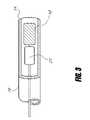
- FIG. 3is a fragmentary cut-away view of a distal end of a deployment catheter having an implantable device therein.
- FIG. 4is a fragmentary view as in FIG. 3 , having a different embodiment illustrated therein.
- FIG. 5is a simplified top view of a section through the heart, illustrating a first valve at a first location in a first pulmonary vein, and a second valve at a second location in a second pulmonary vein.
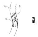
- FIG. 6is a schematic representation of a stent supported valve in a pulmonary vein.
- FIG. 7is a simplified back view of the heart, illustrating the location of the left superior pulmonary vein, left inferior pulmonary vein, right superior pulmonary vein and right inferior pulmonary vein.
- FIG. 8is a simplified view of the lungs and left atrium, illustrating the orientation of the pulmonary veins with respect to the lungs.
- FIG. 9Ais a perspective schematic view of a Starr-Edwards ball and cage valve.
- FIG. 9Bis a perspective schematic view of a single leaflet valve.
- FIG. 9Cis a schematic perspective view of a bi-leaflet valve.
- FIG. 9Dis a schematic perspective view of a Reed style or duckbill valve.
- FIG. 9Eis a schematic perspective view of a poly-leaflet valve.
- FIG. 9Fis a schematic perspective view of a tri-leaflet valve having an inflatable support structure.
- FIG. 9Gis a schematic perspective view of a tri-leaflet valve having an alternative inflatable support structure.
- FIG. 9His an elevational cross-sectional view through the valve of FIG. 9G .
- FIG. 10is a schematic representation of the heart and pulmonary venous circulation following redirection of the pulmonary venous flow into the left ventrical.
- FIG. 11is a cross-sectional view of a ball valve that can be used to control inflation of the inflatable support structure.
- Implantation of valves into the bodyhas been accomplished by a surgical procedure or via percutaneous method such as a catheterization or delivery mechanism utilizing the vasculature pathways.
- Surgical implantation of valves to replace or repair existing valves structuresinclude the four major heart valves (tricuspid, pulmonary, mitral, aortic) and some venous valves in the lower extremities for the treatment of chronic venous insufficiency.
- Implantationincludes the sewing of a new valve to the existing tissue structure for securement. Access to these sites generally include a thoracotomy or a sternotomy for the patient and include a great deal of recovery time.
- An open-heart procedurecan include placing the patient on heart bypass to continue blood flow to vital organs such as the brain during the surgery.
- the bypass pumpwill continue to oxygenate and pump blood to the body's extremities while the heart is stopped and the valve is replaced.
- the valvemay replace in whole or repair defects in the patient's current native valve.
- the devicemay be implanted in a conduit or other structure such as the heart proper or supporting tissue surrounding the heart. Vessels entering or departing the heart have an attachment or connection interface where the two components join in transition. This transition may provide a secure tissue zone to attach a valve body to. Attachments methods may include suturing, hooks or barbs, interference mechanical methods or an adhesion median between the implant and tissue. Access to the implantation site may require opening the wall of the heart to access the vessel or heart tissue for attachment. It is also possible to implant the device directly into the vessel by slitting in the longitudinal direction or cutting circumferentially the vessel and suturing the vessel closed after insertion. This would provide a less invasive method to implant the device surgically.
- Other methodsinclude a catheterization of the body to access the implantation site. Access may be achieved under fluoroscopy visualization and via catheterization of the internal jugular or femoral vein continuing through the vena cava to the right atrium and utilizing a transeptal puncture enter the left atrium. Once into the left atrium conventional and new catheterization tools will help gain access to the pulmonary veins. Engagement of each of the pulmonary veins may require a unique guiding catheter to direct device or catheter placement. Monitoring of hemodynamic changes will be crucial before, during and after placement of the device. Pressure and flow measurements may be recorded in the pulmonary veins and left atrium. Right atrial pressures may be monitored separately but are equally important. Separate catheters to measure these values may be required.
- Valve deliverymay be achieved by a pushable deployment of a self expanding or shaped memory material device, balloon expansion of a plastically deformable material, rotational actuation of a mechanical screw, pulling or pushing force to retract or expose the device to the deployment site.
- radiopaque markersmay be placed on the catheter or device to indicate relative position to known landmarks. After deployment of the devices the hemodynamic monitoring will allow the interventional cardiologist to confirm the function of the valves. It is possible to place and remove each valve independently as valves may not be required in all pulmonary veins.
- Entry to the body with a cathetermay include the internal jugular or femoral vein. This will allow the user to enter the right atrium either superior or inferiorly and complete a transeptal puncture for access into the left atrium. Another approach would be to enter the femoral, brachial or radial artery where the user could access the aortic valve entering the left ventrical. Advancing the device through the left ventrical and past the mitral valve the left atrium can be entered. Utilizing normal cath-lab tools such as guidewires and guide catheters the delivery system or catheter can be advanced to the deployment site. Guidewires may measure 0.010-0.035 inches in diameter and 120-350 centimeters in length.
- a guide cathetermay be used to provide a coaxial support system to advance the delivery catheter through.
- This guiding cathetermay be about 60-180 cm in length and have an outer diameter of 0.040-0.250 inches. It would have a proximal and distal end with a connection hub at the proximal end and may have a radiopaque soft tip at the distal end. It may have a single or multilumen with a wall thickness of 0.005-0.050 inches and may include stiffening members or braid materials made from stainless steel, nickel-titanium or a polymeric strand.
- the catheter materialmay include extruded tubing with multiple durometer zones for transitions in stiffness and support.
- the inner diametermay have a Teflon lining for enhanced coaxial catheter movement by reducing the friction coefficient between the two materials.
- the delivery catheter 10would be constructed by normal means in the industry utilizing extruded tubing, braiding for stiffening means and rotational torqueability.
- the delivery catheter 10has a proximal end 12 and distal end 14 where the proximal end 12 may have a connection hub to mate other cath-lab tools to.
- the distal end 14may have a radiopaque marker to locate under fluoroscopy.
- the outer diameterwould measure about 0.030-0.200 inches and have a wall thickness from about 0.005-0.060 inches.
- the overall lengthwould range from about 80-320 centimeters and have a connection hub or hubs at the proximal end 12 to allow wires, devices and fluid to pass.
- connection hubwould be compatible with normal cath-lab components and utilize a threaded end and a taper fit to maintain seal integrity.
- the inner diameter of the catheter 10would allow for coaxial use to pass items such as guidewires, devices, contrast and other catheters.
- An inner lining materialsuch as Teflon may be used to reduce friction and improve performance in tortuous curves.
- a braided shaft of stainless steel or Nitinol imbedded into the catheter shaft 16may improve the torqueability and aid in maintaining roundness of the catheter lumen.
- Multidurometer materialswould help soften the transition zones and add correct stiffness for pushability in the body. These zones may be achieved through an extrusion process know as bump tubing. Where the material inner and outer diameter change during the extrusion process.
- the entire catheter shaftcan be produced in one piece. Another method for producing such a catheter shaft is to bond separate pieces of tubing together by melting the two components together and forming a single tube with multiple diameters and or stiffness.
- the application of heatcan be applied by laser or heated air that flows over the shaft material or other methods of heat application sufficient to flow the materials together.
- the shaft materialmay also consist of stiffening members for transition zones or bump extrusions to reduced diameter and maintain correct pushability.
- Lumen characteristicsmay include single or multi portals for guidewire or device entry. Conventional guidewire passage through the catheter such as “over-the-wire” may be used or technology such as “rapid-exchange” may aid in procedure ease and catheter exchanges. Since multiple devices may be placed in a single catheterization, rapid-exchange may be preferred but not essential.
- Other features that may aid in ease of useinclude a slippery coating on the outer and or inner diameter such as MDX (silicone) or a hydrophilic layer to allow easy access to tortuous anatomy.
- a balloonit may be necessary to utilize a balloon to radially expand the device to its final diameter and location so an inflation lumen and balloon placed distal to the hub could be used.
- This ballooncould be used to pre-dilate the vessel or ostium where the valve may be implanted.
- elements to transmit signals externallycould be imbedded into the catheter for pressure and flow readings or Doppler information. These may include electrical wires, pressure portal or lumens optical fibers.
- delivery of the device 18 via catheterization of the implantation sitewill include a mechanism to deploy or expel the device 18 into the vessel or atrium.
- This mechanismmay include push or pull members 20 and 21 to transmit forces to the distal portion of the catheter 10 . These forces may be applied externally to the body and utilize a handle 22 at the proximal end 12 of the catheter.
- Means to transmit forces to the distal end 14may also include a rotational member 24 to loosen or tighten, convert a torque 26 into a translational force such as a threaded screw 28 and nut or to add or subtract stiffness to the catheter 10 or device 18 .
- the handle 22 mechanismmay also include a port for hydraulic pressures to be transmitted to the distal portion of the catheter 10 or have the ability to generate hydraulic forces directly with the handle 22 . These forces may include a pushing or pulling transmitted to the device 18 or catheter 10 , an exposure of the device 18 to allow for implantation or to expel the device 18 from the catheter. Further forces may include a radial or longitudinal expansion of the device 18 or catheter 10 to implant or size the location of implantation.
- the handle 22may also include connections to electrical signals to monitor information such as pressures, flow rates, temperature and Doppler information. Another important use of the handle 22 and catheter 10 is the deployment mechanism for the device 18 . As the device 18 is navigated to the site, attachment between the device 18 and catheter 10 is essential.
- the valve devicecan utilize many different methods to implant at the selected site such as an expulsion out the end of the catheter 10 , a mechanical release mechanism such as a pin joint, unscrewing the device 18 from the catheter delivery system, a tethered link such as a thread or wire, a fusible link as used in a GDC coil deployment, a cutting tool to sever a attachment of the device 18 from the catheter 10 , a threaded knot to tether the catheter 10 to the device 18 where the as the knot could be untied or cut, a hydraulic mechanism to deploy, expand or fracture a link between the catheter 10 and the device 18 . All above mentioned concepts may be enhanced be the utilization of a flexible tip to allow acute articulation of the device 18 and delivery catheter 10 to gain access to the implantation site.
- the deviceAfter the device has been temporarily deployed or positioned, it may be advantageous to recapture or reposition the device for optimal results. This may include a rotational or translation of the implant of a complete removal and exchange for a different diameter, length or style device. Capture of an implanted device may require a second catheter to reengage the device to remove or reposition to a proper location.
- the devicesuch as a valve 30
- the devicewould be located between the right lung 31 a and/or left lung 31 b and the left atrium 32 in the right superior pulmonary vein 34 a , the right inferior pulmonary vein 34 b , the left superior pulmonary vein 34 c , the left inferior pulmonary vein 34 d and/or in the wall of the left atrium 32 .
- the valve 30 described aboveis located to affect the flow and pressure of blood between the pulmonary veins 34 a - d and the left atrium 32 or a portion of the left atrium 32 and to lessen the symptoms of mitral regurgitation from a dysfunctional mitral valve 36 including elevations and fluctuations in the pulmonary circulation.
- the device 30may be viewed as a one-way valve limiting or restricting retrograde flow into the pulmonary circulation. Having a substantial fatigue life to withstand cyclical operation for a given period of implantation duration will be a factor in selection of both materials and construction. This may include heat treatments to certain portions or all components of the device 30 and analysis of construction and manufacturing techniques to optimize device 30 life. Additionally a coating may be required to maintain patency of the device 30 during normal operation. This may be a surface modification or treatment, a coating added to the device 30 such as heparin or and albumin layer.
- the valvecould be a valve of any design including bioprosthetic, mechanical or tissue valves.
- Examples of commonly used prosthetic valvesinclude a ball valve 40 illustrated in FIG. 9A such as a Starr-Edwards, a single leaflet valve 50 illustrated in FIG. 9B such as a Bjork-Shiley valve, a bileaflet or bi-disk valve 60 illustrated in FIG. 9C or an artificial tricuspid valve such as a Magna or Cribier, a reed style valve 70 illustrated in FIG. 9D , a slit in a membrane of material, a duckbill style or many other styles unmentioned here but apparent to one skilled in the art.
- valvesmay be deformable to allow for percutaneous delivery or rigid to enable structural integrity. They may include one of the below mentioned features or a combination of a plurality thereof to add performance and or reduce size.
- the early valve implantsbegan in the early 1960's with ball valves 40 such as the Starr-Edwards.
- This valve 40includes a base 42 and mechanical structure 44 where a ball 46 is captured and allowed to travel longitudinally sealing flow in one direction and allowing flow in the other. The movement of the ball 46 is driven by flow.
- disk style valves 50known as Bjork-Shiley, entered the market in the 1970's and began with a single disk 52 supported in a ring 54 where the disk 52 was allowed to pivot within the ring 54 allowing flow in one direction and sealing flow in the other.
- the tilt angleranged from about 60-80 degrees.
- bi-disk valves 60include two tilting disks to allow for greater flow and less turbulence. These valves 60 were introduced in the 1980's and seem to be the standard choice.
- a poly-leaflet valve 80for implantation in the body.
- the valve 80would contain four or more leaflets 82 free to pivot near the annulus 84 of the valve 80 .
- Increasing the number of leaflets 82allows the valve 80 to collapse to a smaller diameter, for percutaneous or minimally invasive delivery, while also providing good hemodynamics, and allowing the leaflets 82 to be made from a rigid material ideally one that has clinically proven good biocompatibility in valve applications.
- a flexible leaflet valvefor implantation in the body.
- a mechanical prosthetic valvemanufactured from a flexible material such as a polymer or tissue material that allows the leaflets to be substantially deformed during delivery if the valve.
- the leafletscould also consist of metal or a polymeric coated sub straight. If metallic the leaflet material could be a super elastic alloy such as Nitinol or an alloy with a relatively high yield stress and relatively low modulus of elasticity such as certain titanium alloys.
- a valve that functions as an iriscould also be utilized as a prosthetic valve.
- the iriscould be opened and closed by an internal or external force, a differential in pressure or by the flow of blood.
- tissue valvesthat have been previously implanted as replacement valves in the human coronary system. These include valves from human cadavers, and valves from other mammals such as pigs horses and cows utilizing sometimes pericardial tissue to build a valve by sewing techniques. Any of these types of valves could be implanted as described both in a surgical procedure or a catheterization. Additionally other valves such as from the larger venous vessels from smaller animals could be utilized because of the smaller size and reduced flow requirements of the pulmonary veins.
- a valve from the patientmay also be used, by transplanting the valve into a pulmonary vein.
- Many native valvescould be used such as a venous valve from the lower extremities.
- the preferred embodimentis to use a native valve from a large peripheral vein.
- the flow control devicecould be an orifice of fixed or adjustable diameter that limits the amount of blood that flows through the pulmonary veins.
- the orifice diametercould be adjusted remotely or by some hemodynamic mechanism such as pressure or flow differential or pressure change.
- the flow control devicecould consist of one or more flaps located within the atrium to prevent the back flow of blood into the pulmonary veins.
- the flow control devicecould be a pivoting or flexible flap that moves to block the ostium of one or more pulmonary veins or it could be a rigid or semi rigid flap or flaps that control the bloods flow path reducing or eliminating the backwards flow of blood in to the pulmonary veins.
- the flow through the valveis flow controlled. To the extent possible flow is allowed only in a first direction and not in a second direction.
- the first directionis intended to be away from the lungs and towards the heart.
- the valvemay function such that it is pressure controlled that is it opens at a preset pressure differential.
- the pressure controlcould be implemented in several ways.
- the one-way valvecould allow flow in the backward or restricted direction at a certain pressure differential. This may be advantageous in preventing the overloading of the atrium.
- the valvecould be designed to open in its normal flow direction at a preset pressure differential.
- the valve or flow control devicemay be manufactured partially or completely from metallic components. Depending on the mechanical properties required various biocompatible metals might be chosen. These include, but are not limited to various stainless steel alloys, cobalt-chrome-nickel-alloys, super-elastic alloys such as Nitinol, Tantalum and titanium and its alloys. The device could be self-expanding in nature if desired.
- the valve or flow control devicemay be manufactured partially or completely from polymeric components.
- Various biocompatible polymersmay be used depending on the desired mechanical properties.
- Some examples of biocompatible polymersinclude silicone, polyethylene and, fluoropolymers such as Teflon.
- All or part of the flow control devicemay attach to the outside of the pulmonary vein by applying external force to the vein the device affects the flow through the vein. Both compressive or expansive forces could be applied to change the vessel geometry. An external portion of the device located around the vein may also help to secure a second portion of the device within the vein.
- Valvesmay be actuated to synchronize with the proper opening and closing times through an internal or external device such as a pacemaker. There may require an actuation device to drive the motion of the valve open and closed. Pressure gradients could be used to sense when actuation is necessary.
- the flow control devicemay include a vane that introduces a swirling motion to the blood.
- the vanemay be used to improve hemodynamic flow through another portion of the flow control device or it may be used alone to improve the hemodynamics of the native anatomy.
- the vanemay additionally function or rotate in a single direction only to limit flow.
- the flow control device located between a portion of the pulmonary veins and the heartconsists of a pump.
- the pumpmay be powered externally, internally or by the biological movement of the heart.
- the pumpmay be located inside the pulmonary vein inside the atrium outside the heart or, outside the body.
- certain pulmonary vein valves in accordance with the present inventioninclude an inflatable support structure 90 , as is disclosed, for example, in the context of an atrial valve, in the provisional applications incorporated by reference above.
- the inflatable support structure 90comprises at least one annular ring 92 , such as an annulus for a valve, which is releasably carried by a deployment catheter having at least one inflation lumen extending therethrough. Following positioning of the valve in the pulmonary vein, the annulus is inflated to the desired size and/or pressure, and thereafter decoupled from the deployment catheter.
- a one wayvalve 102 on the inflatable support structure 90prevents escape of the inflation media and/or allows inflation of the inflatable support structure 90 .
- the one way valve 102can be a ball valve, as illustrated in FIG. 11 , or another type of valve such as a duck bill valve, pinch or flap valve.
- a push wire 106 in the delivery catheter 107can be used to displace the check ball 104 from the default sealing position, thereby unsealing the inflation lumen 105 and permitting the inflatable support structure 90 to be inflated.
- Release tangs 108can be used to secure and align the delivery catheter 107 with the flow control valve 102 .
- the first inflatable chamber 92is provided such as at the annulus of the valve 90
- at least a second inflatable chamber 94is provided, such as to provide commissural support and/or to stabilize the valve 90 , depending upon the occluder (i.e. leaflet) configuration as will be appreciated by those of skill in the art in view of the disclosure herein.
- a first inflatable ring 92is provided at a proximal end 96 of the tubular valve 90
- a second inflatable ring 94is provided at a distal end 98 of the tubular valve 90
- at least one additional inflatable chamber 100is provided in between the proximal and distal ends 96 and 98 , to provide intermediate support.
- the intermediate support chamber 100may comprise any of a variety of configurations, such as a zig-zag configuration around the circumference of the valve support structure.
- a tissue valve or a synthetic leaflet valvemay be secured within the tubular valve support structure 90 .
- the device 110such as a valve, is located substantially outside the heart 112 .
- the right superior pulmonary vein 114 a , the right inferior pulmonary vein 114 b , the left superior pulmonary vein 114 c and the left inferior pulmonary vein 114 dare spliced into and connect together into a prosthetic atrium 116 .
- Bloodis then directed through a one-way valve 110 and through a conduit 118 to the left ventricle 120 .
- the native mitral valvecould be surgically sealed off and/or the native pulmonary veins 114 a ′-d′ could be sealed, restricted, occluded, or cut, near where they connect to the left atrium 122 .
- This procedurecould be performed in an open surgical procedure or in a minimally invasive procedure or percutaneously, ideally the procedure would be performed on a beating heart possibly using a thorascope.
- the prosthesis 116is first flushed and filled with a biocompatible fluid such as saline to prevent the possibility of an air embolism.
- a biocompatible fluidsuch as saline
- the outlet conduit 118is attached to a portion of the native anatomy, preferably the left ventricle 120 , and preferably near the apex of the heart 112 .
- the one way valve 110 portion of the implantprevents blood from the left ventricle 120 from escaping uncontrolled.
- a pulmonary vein 114 a - dis cut.
- the atrium 122 side of the vein 114 a ′-d′is tied off or otherwise sealed.
- the section of the pulmonary vein 114 a - d connected to the lungsis attached to one of the inlet conduits 124 a - d of the prosthesis 116 .
- the remaining pulmonary veins 114 a - dare connected to the prosthesis 116 , preferably one at a time.
- the prosthetic atriumis supplied as a chamber with single outlet conduit 118 and four inlet conduits 124 a - d .
- a one way valve 110is supplied, attached either to the chamber or in the outlet conduit 118 .
- the outlet conduit 118may be designed to allow the insertion and attachment of an available prosthetic valve 110 during the procedure.
- the prosthetic chamberis constructed from a woven fabric, such as polyester.
- the chamberis constructed from animal tissue such as the aortic root of a pig or the pericardial tissue from a cow. These tissues may be fixed using techniques common in the industry, such as glutaraldehyde fixation.
- the bloodis directed from the pulmonary veins, into the prosthetic atrium, past the prosthetic valve and then into the native atrium.
- the prosthetic atriumcould be of any volume, from as small as is practical to larger than a native atrium.
- the compliance of the prosthetic atriumis also a variable that may be adjusted to achieve optimal hemodynamics and to limit pulmonary edema.
- the pulmonary veinsare interrupted and blood is channeled from the portion of the pulmonary vein nearest the lung, through a prosthetic valve and then back into the portion of the pulmonary vein nearest the atrium.
- a valvecould be placed in one or more pulmonary vein.
- multiple veinscould be joined to channel blood to a single valve. The flow of blood could then return to the heart in a single conduit or could be bifurcated into multiple channels and return to the heart, ideally through the ostium where the native pulmonary veins met or meet the atrium.
- the valveis located substantially within the pulmonary veins or the atrium, but the valve is inserted through a slit cut into the pulmonary veins. It is possible that by interrupting flow in less than four of the pulmonary veins and or by a rapid surgical procedure, the use of a heart lung machine would not be required to oxygenate the patients blood.
- the devicecould be implanted at any location within the pulmonary vein and may allow additional compliance if implanted deep into the pulmonary vein. This may allow the vein to dilate during higher pressures relieving pressures seen in the left atrium or pulmonary circulation. Additionally, an accumulation or expansion chamber may added to the pulmonary vasculature to allow for pressure variations. This device could be adjusted or calibrated to the correct or ideal pressures as normally seen in a healthy human and translate them to the pulmonary circulation.
- Another devicemay be located in the left atrium and consist of a bladder containing a fluid such as a gas to relieve excess pressures seen within the left atrium.
- the deviceis located in the pulmonary veins near or at the ostium where the veins empty into the left atrium.
- the valvescould be placed in this location by many methods including surgically or percutaneously delivery.
- the deviceis located further up the pulmonary veins closer to the lungs. This location could effectively produce a more compliant and larger volume atrium than the previous embodiment.
- valveis located substantially within the atrium. With this valve location it may be possible to fit a larger valve for improved hemodynamics, or to allow the valve to cover the flow from more than one pulmonary vein. This may also aid in anchoring the device securely.
- the flow control devicecan be secured in the anatomy by several methods. As illustrated in FIG. 6 , in one embodiment a portion of the device 30 consists of an expandable stent like structure 38 utilizing an interference fit or surface friction to hold the device 30 in place.
- the stent like structure 38could be made from a malleable alloy such as a stainless steel of suitable alloy and condition or cobalt-chromium for better visibility under fluoroscopy. The stent like structure 38 would then be expanded mechanically by a balloon or other means, producing interference fit with the tissue.
- the stent like structure 38could be one of a self-expanding design, manufactured from a super elastic material such as Nitinol, or a material with a large amount of elastic strain available such as the ellgilloy used in the wall stent.
- the stent 38could be manufactured from a tube selectively removing portions with a laser or EDM thus providing optimal expansion and cross-sectional profiles.
- One skilled in the art of stent design and manufacturecould produce many variations of an embodiment as such.
- Another anchoring methodis to suture the valve portion to the wall of the atrium or to the pulmonary vein.
- the flow control devicemay contain a sewing ring to allow sutures to be easily attached to the device.
- a percutaneous or minimally invasive sewing devicemay also be incorporated. This device would contain at least one needle remotely actuated to attach the valve to the tissue, or to a second device previously implanted at the desired valve location.
- Other methodsmay utilize a balloon or other force mechanism to push or pull the suture into position.
- Another anchoring methodis to staple or clip the valve in place with multiple detachable staples, clips, barbs or hooks. This could be accomplished surgically with a tool that spaces the clips around the annulus and allows them to engage the tissue and a portion of the valve.
- the staples, clips, hooks or barbscould also be delivered percutaneously with a device that positions the staples, clips, hooks or barbs relative to the valve. These could be attached through a balloon or other force mechanism to push or pull them into position.
- Another anchoring methodis to use an adhesive to secure the valve to the tissue.
- Adhesivessuch as a fibrin glue or cyanoacrylate could be delivered percutaneously or surgically to attach the valve to the tissue.
- the devicescould be made in a variety of diameters to correspond to the various anatomy of the patient population.
- the ideal size of the flow control device designed to be located inside a pulmonary veinmay not directly correspond to the diameter of the vein.
- an oversize valvemay be preferred because it may offer better hemodynamics or other advantages.
- an undersize valvemay be preferred because it may offer reduced vessel trauma or other advantages.
- the average size of the pulmonary veinsis approximately 15 mm in diameter. These valves would preferably be manufactured in a range of sizes from 3 to 30 mm in diameter, although other sizes may be used.
- a flow control device designed for location in the atriummay have a range of sizes significantly larger than the previous embodiment these valves may preferably range from 8 to 80 mm in diameter, although other sizes may also be used.
- a flow control device designed to be located substantially outside the heart and outside the pulmonary veinsmay include a valve of a range of diameters from 8 to 80 mm.
- An orifice type flow control device if located in the pulmonary veinwould require an outside diameter corresponding to the diameter of the vein.
- the inside diameterwould depend on the desired effect on flow.
- the outside diameterwould preferably be approximately 10-20 mm in diameter and may range from 3 to 30 mm in diameter. Other sizes may also be used.
- the internal diameter of the orificemay range from 1 to 20 mm in diameter.
- An orifice designed to limit flow through the native arteries when a secondary path for blood flow is providedmay be smaller still. In this case an orifice from 0.5 to 5 mm is preferred, although other sizes may be used.
- Length of devicemay vary depending upon the style selected. Disk style devices may range in length from 2-20 millimeters where a ball-cage style may range from 2-30 millimeters in length. It is also possible to implant a plurality or devices into one vessel for additional performance.
- the valve portion of the implantmay be located distal, proximal or coaxial to the anchoring portion of the device.
- the anchoring portion of the devicemay range in length from 2-30 millimeters.
- Devices of similar or identical designcould be used to treat patients with congenital defects.
- a patient with a common atrium, where the septal wall between the left and right atrium is missingcould be treated with a device described above, although the patient does not have a left atrium the common atrium serves its function and a similar device could be effective.
- a patient suffering from a transposition of the great cardiac veinscould be treated with a similar valve.
- the procedureis preferably performed in a cardiac catheterization lab, where the normal tools associated with interventional cardiology are available.
- Many of the conventional toolscould be used for the implantation of a valve controlling the flow through the pulmonary veins. These tools include items such as introducers guide catheters, and guide wires may be used with this device.
- Some devices specifically designed for the valve implantationsuch as special sizing tools to measure diameters and flow characteristics and access tools to engage the pulmonary veins may be used.
- a guide catheter with a special curve or curvesmay be required to access the atrium and pulmonary veins.
- the deviceis to be implanted using fluoroscopic guidance or other visualization means such as CT or MRI.
- a contrast mediasuch as barium sulfate may be used to visualize the coronary anatomy.
- Contrastcould be injected into the pulmonary artery, or one of its branches, to help visualize where the pulmonary veins exit the lungs. Contrast could also be injected from the tip of the guide catheter when engaged into the pulmonary vein to image the ostium clearly for device placement.
- Another method of implanting the valve between the pulmonary veins and the heartis a surgical approach. This procedure is to be performed in a surgical suite.
- the heartmay be exposed by a sternotomy or lateral thoracotomy or through a portal entry or the procedure is performed through a puncture or small incision utilizing a minimally invasive tube like device.
- the aortais cross-clamped and the heart is infused with a cardiopelegic solution.
- a bypass pumpis utilized to provide oxygenated blood to the body especially important organs such as the brain.
- surgical toolsare utilized to allow the procedure to be performed through small incisions in the heart, preventing the need for the use of the bypass pump, and minimizing the risk of associated complications.
- the valvescan be placed in any location that allows the control of blood flow to the atrium from the pulmonary veins and prevents or minimizes back flow.
- the valvescould be placed in the pulmonary veins. This offers advantages for percutaneous placement because the system would use multiple valves of smaller diameter.
- the valvescould also be placed inside the atrium this offers the advantage of possibly implanting larger valves that could control the flow of blood from one or more pulmonary vein.
- the valvescould also be positioned in the ostium of the pulmonary veins; this provides similar advantages to implanting the valves in the pulmonary veins but has the advantage that the tissue may be easier to secure the device to.
- the valve or valvescould also be located outside the heart and the blood flow routed through the valve or valves in a prosthetic conduit.
- access to the pulmonary veinsmay be gained by a puncture into the venous system and a trans-septal puncture from the right atrium into the left atrium.
- access to the venous systemis gained by a puncture into a vein, preferably the internal jugular vein or the femoral vein would be used, but other veins are also suitable.
- access to the pulmonary veinsmay be gained, by a puncture into the arterial system.
- the punctureis preferably performed in the femoral radial or brachial artery although other arteries may be used as well.
- the catheteris then advanced into the aorta, past the aortic valve, past the mitral valve and into the left atrium where it can access the pulmonary veins
- various imaging techniquescan be used. These include fluoroscopy, chest x-ray, CT scan and MRI.
- various flows and pressuresmay be monitored, or example echocardiography may be used to monitor the flow of blood through the pulmonary veins, and other chambers and conduits of the coronary system. It may be especially important to visualize regurgitant flow in the pulmonary veins and past the mitral valve. Additionally pressures may be monitored in various chambers and conduits of the heart; for example pulmonary wedge pressure may be an important measurement.
- the surgical proceduremay be performed on a cardiac bypass pump. This would allow the device to be implanted with the heart stopped and may not require a cross-clamp of the pulmonary vein. Alternatively using some of the devices and concepts described the surgical procedure may be performed off pump. While maintaining a beating heart, the operation may be performed by using a cross-clamp method to isolate a pulmonary vessel using two clamps to halt the blood flow between the site implantation. A slit or incision may then be made to insert the valve device into the vessel. Alternatively, a complete separation of the vessel between the two clamps and exposing the lumen could be made to implant the valve device. Both techniques would require a suture or reattachment of the vessel post implantation and a suture or other means may be required to maintain proper valve location within the vessel. The techniques of implantation of the device would apply to on-pump implants as well.
- This procedureutilizes a device that consists of a conduit approximately 20 mm in diameter and a prosthetic valve located in the conduit. The end of the conduit that allows out flow is grafted into the left ventrical. The one-way valve prevents blood from escaping. The pulmonary veins are then transplanted from the left atrium to the inlet side of the conduit. The small portion of the pulmonary veins remaining on the atrium are closed surgically.
Landscapes
- Health & Medical Sciences (AREA)
- Cardiology (AREA)
- Engineering & Computer Science (AREA)
- Biomedical Technology (AREA)
- Heart & Thoracic Surgery (AREA)
- Transplantation (AREA)
- Oral & Maxillofacial Surgery (AREA)
- Vascular Medicine (AREA)
- Life Sciences & Earth Sciences (AREA)
- Animal Behavior & Ethology (AREA)
- General Health & Medical Sciences (AREA)
- Public Health (AREA)
- Veterinary Medicine (AREA)
- Prostheses (AREA)
- Surgical Instruments (AREA)
Abstract
Description
Claims (5)
Priority Applications (4)
| Application Number | Priority Date | Filing Date | Title |
|---|---|---|---|
| US11/112,847US7641686B2 (en) | 2004-04-23 | 2005-04-22 | Percutaneous heart valve with stentless support |
| US12/502,164US20100010623A1 (en) | 2004-04-23 | 2009-07-13 | Percutaneous heart valve with stentless support |
| US13/450,356US20120277855A1 (en) | 2004-04-23 | 2012-04-18 | Percutaneous heart valve with inflatable support |
| US16/277,775US20200015967A1 (en) | 2004-04-23 | 2019-02-15 | Percutaneous heart valve with inflatable support |
Applications Claiming Priority (15)
| Application Number | Priority Date | Filing Date | Title |
|---|---|---|---|
| US56470804P | 2004-04-23 | 2004-04-23 | |
| US56840204P | 2004-05-05 | 2004-05-05 | |
| US57256104P | 2004-05-19 | 2004-05-19 | |
| US58166404P | 2004-06-21 | 2004-06-21 | |
| US58600604P | 2004-07-07 | 2004-07-07 | |
| US58600504P | 2004-07-07 | 2004-07-07 | |
| US58611004P | 2004-07-07 | 2004-07-07 | |
| US58605504P | 2004-07-07 | 2004-07-07 | |
| US58605404P | 2004-07-07 | 2004-07-07 | |
| US58600204P | 2004-07-07 | 2004-07-07 | |
| US58810604P | 2004-07-15 | 2004-07-15 | |
| US60332404P | 2004-08-20 | 2004-08-20 | |
| US60520404P | 2004-08-27 | 2004-08-27 | |
| US61026904P | 2004-09-16 | 2004-09-16 | |
| US11/112,847US7641686B2 (en) | 2004-04-23 | 2005-04-22 | Percutaneous heart valve with stentless support |
Related Child Applications (1)
| Application Number | Title | Priority Date | Filing Date |
|---|---|---|---|
| US12/502,164ContinuationUS20100010623A1 (en) | 2004-04-23 | 2009-07-13 | Percutaneous heart valve with stentless support |
Publications (2)
| Publication Number | Publication Date |
|---|---|
| US20050273160A1 US20050273160A1 (en) | 2005-12-08 |
| US7641686B2true US7641686B2 (en) | 2010-01-05 |
Family
ID=35450045
Family Applications (4)
| Application Number | Title | Priority Date | Filing Date |
|---|---|---|---|
| US11/112,847Expired - Fee RelatedUS7641686B2 (en) | 2004-04-23 | 2005-04-22 | Percutaneous heart valve with stentless support |
| US12/502,164AbandonedUS20100010623A1 (en) | 2004-04-23 | 2009-07-13 | Percutaneous heart valve with stentless support |
| US13/450,356AbandonedUS20120277855A1 (en) | 2004-04-23 | 2012-04-18 | Percutaneous heart valve with inflatable support |
| US16/277,775AbandonedUS20200015967A1 (en) | 2004-04-23 | 2019-02-15 | Percutaneous heart valve with inflatable support |
Family Applications After (3)
| Application Number | Title | Priority Date | Filing Date |
|---|---|---|---|
| US12/502,164AbandonedUS20100010623A1 (en) | 2004-04-23 | 2009-07-13 | Percutaneous heart valve with stentless support |
| US13/450,356AbandonedUS20120277855A1 (en) | 2004-04-23 | 2012-04-18 | Percutaneous heart valve with inflatable support |
| US16/277,775AbandonedUS20200015967A1 (en) | 2004-04-23 | 2019-02-15 | Percutaneous heart valve with inflatable support |
Country Status (1)
| Country | Link |
|---|---|
| US (4) | US7641686B2 (en) |
Cited By (22)
| Publication number | Priority date | Publication date | Assignee | Title |
|---|---|---|---|---|
| US20060025855A1 (en)* | 2004-05-05 | 2006-02-02 | Lashinski Randall T | Translumenally implantable heart valve with multiple chamber formed in place support |
| US20070005133A1 (en)* | 2005-06-07 | 2007-01-04 | Lashinski Randall T | Stentless aortic valve replacement with high radial strength |
| US20090088836A1 (en)* | 2007-08-23 | 2009-04-02 | Direct Flow Medical, Inc. | Translumenally implantable heart valve with formed in place support |
| US20100010623A1 (en)* | 2004-04-23 | 2010-01-14 | Direct Flow Medical, Inc. | Percutaneous heart valve with stentless support |
| US20110166648A1 (en)* | 2006-10-19 | 2011-07-07 | Direct Flow Medical, Inc. | Profile reduction of valve implant |
| US8288879B1 (en)* | 2011-08-02 | 2012-10-16 | Harper Jack R | Highway generator system |
| US8556881B2 (en) | 2006-10-19 | 2013-10-15 | Direct Flow Medical, Inc. | Catheter guidance through a calcified aortic valve |
| WO2013165896A1 (en) | 2012-05-01 | 2013-11-07 | Direct Flow Medical, Inc. | Prosthetic implant delivery device with introducer catheter |
| WO2016025733A1 (en) | 2014-08-15 | 2016-02-18 | Direct Flow Medical, Inc. | Prosthetic implant delivery device |
| US9301835B2 (en) | 2012-06-04 | 2016-04-05 | Edwards Lifesciences Corporation | Pre-assembled bioprosthetic valve and sealed conduit |
| US9375312B2 (en) | 2010-07-09 | 2016-06-28 | Highlife Sas | Transcatheter atrio-ventricular valve prosthesis |
| US9585748B2 (en) | 2012-09-25 | 2017-03-07 | Edwards Lifesciences Corporation | Methods for replacing a native heart valve and aorta with a prosthetic heart valve and conduit |
| US9603708B2 (en) | 2010-05-19 | 2017-03-28 | Dfm, Llc | Low crossing profile delivery catheter for cardiovascular prosthetic implant |
| US9844436B2 (en) | 2012-10-26 | 2017-12-19 | Edwards Lifesciences Corporation | Aortic valve and conduit graft implant tool |
| US10119882B2 (en) | 2015-03-10 | 2018-11-06 | Edwards Lifesciences Corporation | Surgical conduit leak testing |
| DE102017121143A1 (en) | 2017-09-13 | 2019-03-14 | Universitätsklinikum Hamburg-Eppendorf (UKE) | Implantable valve prosthesis |
| US10940167B2 (en) | 2012-02-10 | 2021-03-09 | Cvdevices, Llc | Methods and uses of biological tissues for various stent and other medical applications |
| US10939998B2 (en) | 2015-12-30 | 2021-03-09 | Caisson Interventional, LLC | Systems and methods for heart valve therapy |
| US11406495B2 (en) | 2013-02-11 | 2022-08-09 | Cook Medical Technologies Llc | Expandable support frame and medical device |
| US11974913B2 (en) | 2014-10-13 | 2024-05-07 | Edwards Lifesciences Corporation | Prosthetic valved conduit |
| US20240252301A1 (en)* | 2020-06-23 | 2024-08-01 | Uromedia, Inc. | Method and apparatus for fixation of implantable device for urinary continence |
| US12324741B2 (en) | 2019-01-24 | 2025-06-10 | Artract Medical Inc. | Medical chamber system, introduction system and kit |
Families Citing this family (120)
| Publication number | Priority date | Publication date | Assignee | Title |
|---|---|---|---|---|
| EP2133030A1 (en) | 1997-06-27 | 2009-12-16 | The Trustees of Columbia University of the City of New York | Method and apparatus for circulatory valve repair |
| FR2768324B1 (en) | 1997-09-12 | 1999-12-10 | Jacques Seguin | SURGICAL INSTRUMENT FOR PERCUTANEOUSLY FIXING TWO AREAS OF SOFT TISSUE, NORMALLY MUTUALLY REMOTE, TO ONE ANOTHER |
| US8216256B2 (en) | 1999-04-09 | 2012-07-10 | Evalve, Inc. | Detachment mechanism for implantable fixation devices |
| US20040044350A1 (en) | 1999-04-09 | 2004-03-04 | Evalve, Inc. | Steerable access sheath and methods of use |
| US10327743B2 (en) | 1999-04-09 | 2019-06-25 | Evalve, Inc. | Device and methods for endoscopic annuloplasty |
| US7811296B2 (en) | 1999-04-09 | 2010-10-12 | Evalve, Inc. | Fixation devices for variation in engagement of tissue |
| US6752813B2 (en) | 1999-04-09 | 2004-06-22 | Evalve, Inc. | Methods and devices for capturing and fixing leaflets in valve repair |
| AU770243B2 (en) | 1999-04-09 | 2004-02-19 | Evalve, Inc. | Methods and apparatus for cardiac valve repair |
| US7226467B2 (en) | 1999-04-09 | 2007-06-05 | Evalve, Inc. | Fixation device delivery catheter, systems and methods of use |
| US6440164B1 (en) | 1999-10-21 | 2002-08-27 | Scimed Life Systems, Inc. | Implantable prosthetic valve |
| EP1113497A3 (en)* | 1999-12-29 | 2006-01-25 | Texas Instruments Incorporated | Semiconductor package with conductor impedance selected during assembly |
| US6602286B1 (en) | 2000-10-26 | 2003-08-05 | Ernst Peter Strecker | Implantable valve system |
| FR2826863B1 (en) | 2001-07-04 | 2003-09-26 | Jacques Seguin | ASSEMBLY FOR PLACING A PROSTHETIC VALVE IN A BODY CONDUIT |
| US6575971B2 (en) | 2001-11-15 | 2003-06-10 | Quantum Cor, Inc. | Cardiac valve leaflet stapler device and methods thereof |
| US6752828B2 (en) | 2002-04-03 | 2004-06-22 | Scimed Life Systems, Inc. | Artificial valve |
| AU2003285943B2 (en) | 2002-10-24 | 2008-08-21 | Boston Scientific Limited | Venous valve apparatus and method |
| US6945957B2 (en) | 2002-12-30 | 2005-09-20 | Scimed Life Systems, Inc. | Valve treatment catheter and methods |
| US10631871B2 (en) | 2003-05-19 | 2020-04-28 | Evalve, Inc. | Fixation devices, systems and methods for engaging tissue |
| US7621948B2 (en)* | 2003-07-21 | 2009-11-24 | The Trustees Of The University Of Pennsylvania | Percutaneous heart valve |
| US7854761B2 (en) | 2003-12-19 | 2010-12-21 | Boston Scientific Scimed, Inc. | Methods for venous valve replacement with a catheter |
| US8128681B2 (en) | 2003-12-19 | 2012-03-06 | Boston Scientific Scimed, Inc. | Venous valve apparatus, system, and method |
| US20070038283A1 (en)* | 2004-02-06 | 2007-02-15 | Mustapha Jihad A | Ostial stent and balloon |
| JP4774048B2 (en) | 2004-05-14 | 2011-09-14 | エヴァルヴ インコーポレイテッド | Locking mechanism of fixing device engaged with tissue and tissue engaging method |
| US7566343B2 (en) | 2004-09-02 | 2009-07-28 | Boston Scientific Scimed, Inc. | Cardiac valve, system, and method |
| WO2006037073A2 (en) | 2004-09-27 | 2006-04-06 | Evalve, Inc. | Methods and devices for tissue grasping and assessment |
| US8052592B2 (en) | 2005-09-27 | 2011-11-08 | Evalve, Inc. | Methods and devices for tissue grasping and assessment |
| US7854755B2 (en) | 2005-02-01 | 2010-12-21 | Boston Scientific Scimed, Inc. | Vascular catheter, system, and method |
| US20060173490A1 (en) | 2005-02-01 | 2006-08-03 | Boston Scientific Scimed, Inc. | Filter system and method |
| CA2597066C (en) | 2005-02-07 | 2014-04-15 | Evalve, Inc. | Methods, systems and devices for cardiac valve repair |
| WO2011034628A1 (en) | 2005-02-07 | 2011-03-24 | Evalve, Inc. | Methods, systems and devices for cardiac valve repair |
| US7780722B2 (en) | 2005-02-07 | 2010-08-24 | Boston Scientific Scimed, Inc. | Venous valve apparatus, system, and method |
| US7670368B2 (en) | 2005-02-07 | 2010-03-02 | Boston Scientific Scimed, Inc. | Venous valve apparatus, system, and method |
| US7867274B2 (en) | 2005-02-23 | 2011-01-11 | Boston Scientific Scimed, Inc. | Valve apparatus, system and method |
| US8197534B2 (en)* | 2005-03-31 | 2012-06-12 | Cook Medical Technologies Llc | Valve device with inflatable chamber |
| US7722666B2 (en) | 2005-04-15 | 2010-05-25 | Boston Scientific Scimed, Inc. | Valve apparatus, system and method |
| US8012198B2 (en) | 2005-06-10 | 2011-09-06 | Boston Scientific Scimed, Inc. | Venous valve, system, and method |
| US7569071B2 (en) | 2005-09-21 | 2009-08-04 | Boston Scientific Scimed, Inc. | Venous valve, system, and method with sinus pocket |
| US7799038B2 (en) | 2006-01-20 | 2010-09-21 | Boston Scientific Scimed, Inc. | Translumenal apparatus, system, and method |
| US20070185571A1 (en)* | 2006-02-06 | 2007-08-09 | The Cleveland Clinic Foundation | Apparatus and method for treating a regurgitant valve |
| US8652201B2 (en)* | 2006-04-26 | 2014-02-18 | The Cleveland Clinic Foundation | Apparatus and method for treating cardiovascular diseases |
| WO2007127477A2 (en)* | 2006-04-27 | 2007-11-08 | Synecor, Llc | Renal blood flow augmentation for congestive heart failure treatment |
| WO2007127433A2 (en)* | 2006-04-28 | 2007-11-08 | Medtronic, Inc. | Method and apparatus for cardiac valve replacement |
| WO2008022077A2 (en)* | 2006-08-14 | 2008-02-21 | Buch Wally S | Methods and apparatus for mitral valve repair |
| WO2008091493A1 (en) | 2007-01-08 | 2008-07-31 | California Institute Of Technology | In-situ formation of a valve |
| US7967853B2 (en) | 2007-02-05 | 2011-06-28 | Boston Scientific Scimed, Inc. | Percutaneous valve, system and method |
| US8828079B2 (en) | 2007-07-26 | 2014-09-09 | Boston Scientific Scimed, Inc. | Circulatory valve, system and method |
| US7892276B2 (en) | 2007-12-21 | 2011-02-22 | Boston Scientific Scimed, Inc. | Valve with delayed leaflet deployment |
| EP2477555B1 (en) | 2009-09-15 | 2013-12-25 | Evalve, Inc. | Device for cardiac valve repair |
| EP3120811A3 (en) | 2009-09-17 | 2017-04-19 | Abbott Vascular | Methods, systems and devices for cardiac valve repair |
| JP6270477B2 (en) | 2010-08-18 | 2018-01-31 | ボストン サイエンティフィック ニューロモデュレイション コーポレイション | User interface for segmented neurostimulation leads |
| US9668859B2 (en) | 2011-08-05 | 2017-06-06 | California Institute Of Technology | Percutaneous heart valve delivery systems |
| US10307167B2 (en) | 2012-12-14 | 2019-06-04 | Corquest Medical, Inc. | Assembly and method for left atrial appendage occlusion |
| US10314594B2 (en) | 2012-12-14 | 2019-06-11 | Corquest Medical, Inc. | Assembly and method for left atrial appendage occlusion |
| US10813630B2 (en) | 2011-08-09 | 2020-10-27 | Corquest Medical, Inc. | Closure system for atrial wall |
| EP2747709A4 (en)* | 2011-09-09 | 2015-04-15 | Univ Emory | SYSTEMS, DEVICES AND METHODS FOR REPAIRING CARDIAC VALVE LESIONS |
| US8945177B2 (en) | 2011-09-13 | 2015-02-03 | Abbott Cardiovascular Systems Inc. | Gripper pusher mechanism for tissue apposition systems |
| CN104114127B (en) | 2011-12-09 | 2017-09-05 | 爱德华兹生命科学公司 | Prosthetic heart valve with improved commissural support |
| US20140142689A1 (en) | 2012-11-21 | 2014-05-22 | Didier De Canniere | Device and method of treating heart valve malfunction |
| WO2014144247A1 (en) | 2013-03-15 | 2014-09-18 | Arash Kheradvar | Handle mechanism and functionality for repositioning and retrieval of transcatheter heart valves |
| WO2015048178A2 (en)* | 2013-09-25 | 2015-04-02 | Heartflow, Inc. | Systems and methods for visualizing elongated structures and detecting branches therein |
| US9566443B2 (en) | 2013-11-26 | 2017-02-14 | Corquest Medical, Inc. | System for treating heart valve malfunction including mitral regurgitation |
| US10390943B2 (en) | 2014-03-17 | 2019-08-27 | Evalve, Inc. | Double orifice device for transcatheter mitral valve replacement |
| US9572666B2 (en) | 2014-03-17 | 2017-02-21 | Evalve, Inc. | Mitral valve fixation device removal devices and methods |
| US10076402B2 (en)* | 2014-06-26 | 2018-09-18 | Cook Medical Technologies Llc | Vascular filter with pressure sensor and valve |
| US10667931B2 (en)* | 2014-07-20 | 2020-06-02 | Restore Medical Ltd. | Pulmonary artery implant apparatus and methods of use thereof |
| US9700445B2 (en) | 2014-11-04 | 2017-07-11 | Abbott Cardiovascular Systems, Inc. | One-way actuator knob |
| US10842626B2 (en) | 2014-12-09 | 2020-11-24 | Didier De Canniere | Intracardiac device to correct mitral regurgitation |
| US10188392B2 (en) | 2014-12-19 | 2019-01-29 | Abbott Cardiovascular Systems, Inc. | Grasping for tissue repair |
| US10524912B2 (en) | 2015-04-02 | 2020-01-07 | Abbott Cardiovascular Systems, Inc. | Tissue fixation devices and methods |
| US10232564B2 (en)* | 2015-04-29 | 2019-03-19 | Edwards Lifesciences Corporation | Laminated sealing member for prosthetic heart valve |
| BR102015011376B1 (en) | 2015-05-18 | 2023-04-04 | Murilo Pundek Rocha | IMPLANTABLE ARTIFICIAL BRONCHI |
| US20160338834A1 (en)* | 2015-05-21 | 2016-11-24 | Cook Medical Technologies Llc | Medical siphon |
| US10376673B2 (en) | 2015-06-19 | 2019-08-13 | Evalve, Inc. | Catheter guiding system and methods |
| US10238494B2 (en) | 2015-06-29 | 2019-03-26 | Evalve, Inc. | Self-aligning radiopaque ring |
| US10667815B2 (en) | 2015-07-21 | 2020-06-02 | Evalve, Inc. | Tissue grasping devices and related methods |
| US10413408B2 (en) | 2015-08-06 | 2019-09-17 | Evalve, Inc. | Delivery catheter systems, methods, and devices |
| US10238495B2 (en) | 2015-10-09 | 2019-03-26 | Evalve, Inc. | Delivery catheter handle and methods of use |
| EP3423005A4 (en) | 2016-03-01 | 2019-11-13 | Paul A. Spence | System, devices and methods for anchoring and/or sealing a heart valve prosthesis |
| US10736632B2 (en) | 2016-07-06 | 2020-08-11 | Evalve, Inc. | Methods and devices for valve clip excision |
| US11771434B2 (en) | 2016-09-28 | 2023-10-03 | Restore Medical Ltd. | Artery medical apparatus and methods of use thereof |
| US11071564B2 (en) | 2016-10-05 | 2021-07-27 | Evalve, Inc. | Cardiac valve cutting device |
| US10363138B2 (en) | 2016-11-09 | 2019-07-30 | Evalve, Inc. | Devices for adjusting the curvature of cardiac valve structures |
| US10398553B2 (en) | 2016-11-11 | 2019-09-03 | Evalve, Inc. | Opposing disk device for grasping cardiac valve tissue |
| US10426616B2 (en) | 2016-11-17 | 2019-10-01 | Evalve, Inc. | Cardiac implant delivery system |
| US10779837B2 (en) | 2016-12-08 | 2020-09-22 | Evalve, Inc. | Adjustable arm device for grasping tissues |
| US10314586B2 (en) | 2016-12-13 | 2019-06-11 | Evalve, Inc. | Rotatable device and method for fixing tricuspid valve tissue |
| US10653523B2 (en) | 2017-01-19 | 2020-05-19 | 4C Medical Technologies, Inc. | Systems, methods and devices for delivery systems, methods and devices for implanting prosthetic heart valves |
| US10561495B2 (en) | 2017-01-24 | 2020-02-18 | 4C Medical Technologies, Inc. | Systems, methods and devices for two-step delivery and implantation of prosthetic heart valve |
| US12029647B2 (en) | 2017-03-07 | 2024-07-09 | 4C Medical Technologies, Inc. | Systems, methods and devices for prosthetic heart valve with single valve leaflet |
| WO2018209313A1 (en) | 2017-05-12 | 2018-11-15 | Evalve, Inc. | Long arm valve repair clip |
| WO2018225059A1 (en) | 2017-06-05 | 2018-12-13 | Restore Medical Ltd | Double walled fixed length stent like apparatus and methods of use thereof |
| US12036113B2 (en) | 2017-06-14 | 2024-07-16 | 4C Medical Technologies, Inc. | Delivery of heart chamber prosthetic valve implant |
| IL274054B2 (en) | 2017-10-19 | 2024-12-01 | Anteris Tech Corporation | Replacement heart valve with reduced suturing |
| US20190167409A1 (en)* | 2017-12-04 | 2019-06-06 | 4C Medical Technologies, Inc. | Devices and method for modifying blood pressure in the lungs and pulmonary vasculature by implanting flow modifier(s) in pulmonary vein(s) |
| US11925549B2 (en) | 2018-05-18 | 2024-03-12 | Anteris Technologies Corporation | Heart valve with gathered sealing region |
| CN112584797A (en) | 2018-05-18 | 2021-03-30 | 安特瑞斯技术公司 | Inverted heart valve for transcatheter valve replacement |
| EP3793482A4 (en) | 2018-05-18 | 2022-03-16 | Anteris Technologies Corporation | HEART VALVE REPLACEMENT ARRANGEMENT WITH A VALVE DISTALLY STENT LOADED |
| US11857441B2 (en) | 2018-09-04 | 2024-01-02 | 4C Medical Technologies, Inc. | Stent loading device |
| US12102531B2 (en) | 2018-10-22 | 2024-10-01 | Evalve, Inc. | Tissue cutting systems, devices and methods |
| EP4252712B1 (en)* | 2018-11-19 | 2025-03-26 | Pulmair Medical, Inc. | Implantable artificial bronchus |
| WO2020117888A1 (en)* | 2018-12-06 | 2020-06-11 | Edwards Lifesciences Corporation | Unidirectional valvular implant |
| JP7530906B2 (en) | 2019-02-06 | 2024-08-08 | インキュベート メディカル テクノロジーズ、 エルエルシー | Intracardiac left atrium and dual assist system |
| US11452628B2 (en) | 2019-04-15 | 2022-09-27 | 4C Medical Technologies, Inc. | Loading systems for collapsible prosthetic heart valve devices and methods thereof |
| JP7543391B2 (en) | 2019-07-15 | 2024-09-02 | エバルブ,インコーポレイティド | Method of Actuating Individual Proximal Elements |
| USD902407S1 (en) | 2019-11-19 | 2020-11-17 | Pulmair Medical, Inc. | Implantable artificial bronchus |
| AU2020417811A1 (en)* | 2020-01-03 | 2022-08-25 | inQB8 Medical Technologies, LLC | Pulmonary vein shield and methods of use |
| US11931253B2 (en) | 2020-01-31 | 2024-03-19 | 4C Medical Technologies, Inc. | Prosthetic heart valve delivery system: ball-slide attachment |
| US12133797B2 (en) | 2020-01-31 | 2024-11-05 | 4C Medical Technologies, Inc. | Prosthetic heart valve delivery system: paddle attachment feature |
| US12053375B2 (en) | 2020-03-05 | 2024-08-06 | 4C Medical Technologies, Inc. | Prosthetic mitral valve with improved atrial and/or annular apposition and paravalvular leakage mitigation |
| US11992403B2 (en) | 2020-03-06 | 2024-05-28 | 4C Medical Technologies, Inc. | Devices, systems and methods for improving recapture of prosthetic heart valve device with stent frame having valve support with inwardly stent cells |
| US12178444B2 (en) | 2020-05-06 | 2024-12-31 | Evalve, Inc. | Clip removal systems and methods |
| US12171486B2 (en) | 2020-05-06 | 2024-12-24 | Evalve, Inc. | Devices and methods for clip separation |
| US12048448B2 (en) | 2020-05-06 | 2024-07-30 | Evalve, Inc. | Leaflet grasping and cutting device |
| US12171485B2 (en) | 2020-05-06 | 2024-12-24 | Evalve, Inc. | Systems and methods for leaflet cutting using a hook catheter |
| US12414811B2 (en) | 2020-05-06 | 2025-09-16 | Evalve, Inc. | Devices and methods for leaflet cutting |
| US11969347B2 (en) | 2020-05-13 | 2024-04-30 | Evalve, Inc. | Methods, systems, and devices for deploying an implant |
| US20230248513A1 (en) | 2020-07-07 | 2023-08-10 | Anteris Technologies Corporation | Expandable frame for improved hemodynamic performance of transcatheter replacement heart valve |
| USD954953S1 (en) | 2020-11-03 | 2022-06-14 | Pulmair Medical, Inc. | Implantable artificial bronchus |
| US11622853B1 (en) | 2022-09-30 | 2023-04-11 | Anteris Technologies Corporation | Prosthetic heart valves |
| USD1014758S1 (en) | 2023-04-19 | 2024-02-13 | Pulmair Medical, Inc. | Implantable artificial bronchus |
Citations (179)
| Publication number | Priority date | Publication date | Assignee | Title |
|---|---|---|---|---|
| US3416562A (en) | 1965-10-15 | 1968-12-17 | Lucas Industries Ltd | Heart valve |
| US3657744A (en) | 1970-05-08 | 1972-04-25 | Univ Minnesota | Method for fixing prosthetic implants in a living body |
| US3671979A (en) | 1969-09-23 | 1972-06-27 | Univ Utah | Catheter mounted artificial heart valve for implanting in close proximity to a defective natural heart valve |
| US3714671A (en) | 1970-11-30 | 1973-02-06 | Cutter Lab | Tissue-type heart valve with a graft support ring or stent |
| US4035849A (en) | 1975-11-17 | 1977-07-19 | William W. Angell | Heart valve stent and process for preparing a stented heart valve prosthesis |
| US4056854A (en) | 1976-09-28 | 1977-11-08 | The United States Of America As Represented By The Department Of Health, Education And Welfare | Aortic heart valve catheter |
| US4106129A (en) | 1976-01-09 | 1978-08-15 | American Hospital Supply Corporation | Supported bioprosthetic heart valve with compliant orifice ring |
| US4183102A (en) | 1977-09-08 | 1980-01-15 | Jacques Guiset | Inflatable prosthetic device for lining a body duct |
| US4339831A (en) | 1981-03-27 | 1982-07-20 | Medtronic, Inc. | Dynamic annulus heart valve and reconstruction ring |
| US4592340A (en) | 1984-05-02 | 1986-06-03 | Boyles Paul W | Artificial catheter means |
| US4612011A (en) | 1983-07-22 | 1986-09-16 | Hans Kautzky | Central occluder semi-biological heart valve |
| US4662885A (en) | 1985-09-03 | 1987-05-05 | Becton, Dickinson And Company | Percutaneously deliverable intravascular filter prosthesis |
| US4727873A (en) | 1984-04-17 | 1988-03-01 | Mobin Uddin Kazi | Embolus trap |
| US4750488A (en) | 1986-05-19 | 1988-06-14 | Sonomed Technology, Inc. | Vibration apparatus preferably for endoscopic ultrasonic aspirator |
| US4750901A (en) | 1986-03-07 | 1988-06-14 | Molteno Anthony C B | Implant for drainage of aqueous humour |
| US4787899A (en) | 1983-12-09 | 1988-11-29 | Lazarus Harrison M | Intraluminal graft device, system and method |
| US4817600A (en) | 1987-05-22 | 1989-04-04 | Medi-Tech, Inc. | Implantable filter |
| US4827911A (en) | 1986-04-02 | 1989-05-09 | Cooper Lasersonics, Inc. | Method and apparatus for ultrasonic surgical fragmentation and removal of tissue |
| US4892541A (en) | 1982-11-29 | 1990-01-09 | Tascon Medical Technology Corporation | Heart valve prosthesis |
| US4922902A (en) | 1986-05-19 | 1990-05-08 | Valleylab, Inc. | Method for removing cellular material with endoscopic ultrasonic aspirator |
| US4931047A (en) | 1987-09-30 | 1990-06-05 | Cavitron, Inc. | Method and apparatus for providing enhanced tissue fragmentation and/or hemostasis |
| US4960424A (en) | 1988-06-30 | 1990-10-02 | Grooters Ronald K | Method of replacing a defective atrio-ventricular valve with a total atrio-ventricular valve bioprosthesis |
| US4994077A (en) | 1989-04-21 | 1991-02-19 | Dobben Richard L | Artificial heart valve for implantation in a blood vessel |
| US5015227A (en) | 1987-09-30 | 1991-05-14 | Valleylab Inc. | Apparatus for providing enhanced tissue fragmentation and/or hemostasis |
| US5026383A (en) | 1989-06-14 | 1991-06-25 | Nobles Anthony A | Apparatus for in-situ cutting of valves within veins and method therefor |
| US5032128A (en) | 1988-07-07 | 1991-07-16 | Medtronic, Inc. | Heart valve prosthesis |
| WO1991017720A1 (en) | 1990-05-18 | 1991-11-28 | Henning Rud Andersen | A valve prosthesis for implantation in the body and a catheter for implantating such valve prosthesis |
| US5163953A (en) | 1992-02-10 | 1992-11-17 | Vince Dennis J | Toroidal artificial heart valve stent |
| US5163897A (en) | 1989-10-25 | 1992-11-17 | Lester Persky | Incontinent prothesis and method |
| US5167628A (en) | 1991-05-02 | 1992-12-01 | Boyles Paul W | Aortic balloon catheter assembly for indirect infusion of the coronary arteries |
| WO1993001768A1 (en) | 1991-07-16 | 1993-02-04 | Stevens John H | Endovascular aortic valve replacement |
| US5207695A (en) | 1989-06-19 | 1993-05-04 | Trout Iii Hugh H | Aortic graft, implantation device, and method for repairing aortic aneurysm |
| US5360444A (en) | 1991-03-19 | 1994-11-01 | Kenji Kusuhara | Occluder supporter and a method of attachment thereof |
| US5370691A (en) | 1993-01-26 | 1994-12-06 | Target Therapeutics, Inc. | Intravascular inflatable stent |
| US5397351A (en) | 1991-05-13 | 1995-03-14 | Pavcnik; Dusan | Prosthetic valve for percutaneous insertion |
| US5411552A (en) | 1990-05-18 | 1995-05-02 | Andersen; Henning R. | Valve prothesis for implantation in the body and a catheter for implanting such valve prothesis |
| US5423851A (en) | 1994-03-06 | 1995-06-13 | Samuels; Shaun L. W. | Method and apparatus for affixing an endoluminal device to the walls of tubular structures within the body |
| US5443499A (en) | 1993-01-14 | 1995-08-22 | Meadox Medicals, Inc. | Radially expandable tubular prosthesis |
| US5449385A (en) | 1991-05-08 | 1995-09-12 | Nika Health Products Limited | Support for a heart valve prosthesis |
| WO1996002212A1 (en) | 1994-07-18 | 1996-02-01 | Block Peter C | Transluminally implantable inflatable prosthetic cardiovascular valve |
| US5500014A (en)* | 1989-05-31 | 1996-03-19 | Baxter International Inc. | Biological valvular prothesis |
| US5616149A (en) | 1990-07-03 | 1997-04-01 | Cedars-Sinai Medical Center | Balloon catheter with cutting edge |
| US5649978A (en) | 1993-05-11 | 1997-07-22 | Target Therapeutics, Inc. | Temporary inflatable intravascular prosthesis |
| US5690570A (en) | 1995-09-26 | 1997-11-25 | Industrial Development Bureau | Multistage sprocket assembly for a bicycle |
| US5817102A (en) | 1992-05-08 | 1998-10-06 | Schneider (Usa) Inc. | Apparatus for delivering and deploying a stent |
| US5848964A (en) | 1997-06-06 | 1998-12-15 | Samuels; Shaun Lawrence Wilkie | Temporary inflatable filter device and method of use |
| US5855601A (en) | 1996-06-21 | 1999-01-05 | The Trustees Of Columbia University In The City Of New York | Artificial heart valve and method and device for implanting the same |
| US5871537A (en)* | 1996-02-13 | 1999-02-16 | Scimed Life Systems, Inc. | Endovascular apparatus |
| US5957949A (en) | 1997-05-01 | 1999-09-28 | World Medical Manufacturing Corp. | Percutaneous placement valve stent |
| US5980570A (en) | 1998-03-27 | 1999-11-09 | Sulzer Carbomedics Inc. | System and method for implanting an expandable medical device into a body |
| US6007575A (en) | 1997-06-06 | 1999-12-28 | Samuels; Shaun Laurence Wilkie | Inflatable intraluminal stent and method for affixing same within the human body |
| US6090139A (en) | 1996-06-12 | 2000-07-18 | Lemelson; Jerome H. | Medical devices using electrosensitive gels |
| WO2000041652A1 (en) | 1999-01-12 | 2000-07-20 | Brice Letac | Prosthetic heart valve implantable by catheter insertion or surgically |
| US6102944A (en) | 1997-03-27 | 2000-08-15 | Edwards Lifesciences Corporation | Methods of tissue heart valve assembly |
| US6110201A (en)* | 1999-02-18 | 2000-08-29 | Venpro | Bifurcated biological pulmonary valved conduit |
| US6117106A (en) | 1997-11-18 | 2000-09-12 | Advanced Cardiovascular Systems, Inc. | Perfusion catheter with coil supported inner tubular member |
| US6126007A (en) | 1998-12-30 | 2000-10-03 | St. Jude Medical, Inc. | Tissue valve holder |
| US6196996B1 (en) | 1993-07-15 | 2001-03-06 | Paul S. Teirstein | Irradiation catheter and method of use |
| US6221096B1 (en) | 1997-06-09 | 2001-04-24 | Kanto Special Steel Works, Ltd. | Intravascular stent |
| US20010007956A1 (en) | 1996-12-31 | 2001-07-12 | Brice Letac | Valve prosthesis for implantation in body channels |
| US6280412B1 (en) | 1999-06-17 | 2001-08-28 | Scimed Life Systems, Inc. | Stent securement by balloon modification |
| US20010021872A1 (en) | 1999-12-31 | 2001-09-13 | Bailey Steven R. | Endoluminal cardiac and venous valve prostheses and methods of manufacture and delivery thereof |
| US6299637B1 (en) | 1999-08-20 | 2001-10-09 | Samuel M. Shaolian | Transluminally implantable venous valve |
| US6309399B1 (en) | 1996-07-17 | 2001-10-30 | Scimed Life Systems, Inc. | Atherectomy device having trapping and excising means for removal of plaque from the aorta and other arteries |
| US6312465B1 (en) | 1999-07-23 | 2001-11-06 | Sulzer Carbomedics Inc. | Heart valve prosthesis with a resiliently deformable retaining member |
| US6371970B1 (en) | 1999-07-30 | 2002-04-16 | Incept Llc | Vascular filter having articulation region and methods of use in the ascending aorta |
| US6371983B1 (en) | 1999-10-04 | 2002-04-16 | Ernest Lane | Bioprosthetic heart valve |
| US6395019B2 (en) | 1998-02-09 | 2002-05-28 | Trivascular, Inc. | Endovascular graft |
| US6409759B1 (en) | 1999-12-30 | 2002-06-25 | St. Jude Medical, Inc. | Harvested tissue heart valve with sewing rim |
| US20020082689A1 (en) | 2000-12-21 | 2002-06-27 | Chinn Joseph Andrew | Polymeric heart valve fabricated from polyurethane/polysiliconeurethane blends |
| US20020095116A1 (en) | 2000-12-15 | 2002-07-18 | Strecter Richard B. | Apparatus and method for replacing aortic valve |
| US6425916B1 (en) | 1999-02-10 | 2002-07-30 | Michi E. Garrison | Methods and devices for implanting cardiac valves |
| US6440164B1 (en) | 1999-10-21 | 2002-08-27 | Scimed Life Systems, Inc. | Implantable prosthetic valve |
| US20020123802A1 (en) | 2000-02-02 | 2002-09-05 | Snyders Robert V. | Artificial heart valve, implantation instrument and method therefor |
| US6458156B1 (en) | 1996-05-31 | 2002-10-01 | The University Of Western Ontario | Expansible bioprosthetic valve stent |
| US20020151961A1 (en) | 2000-01-31 | 2002-10-17 | Lashinski Randall T. | Medical system and method for remodeling an extravascular tissue structure |
| US20020183841A1 (en) | 2001-03-23 | 2002-12-05 | Cohn William E. | Method and apparatus for reducing mitral regurgitation |
| US20020183838A1 (en) | 2001-03-29 | 2002-12-05 | Liddicoat John R. | Method and apparatus for improving mitral valve function |
| US6494909B2 (en) | 2000-12-01 | 2002-12-17 | Prodesco, Inc. | Endovascular valve |
| US6503272B2 (en) | 2001-03-21 | 2003-01-07 | Cordis Corporation | Stent-based venous valves |
| US6508833B2 (en) | 1998-06-02 | 2003-01-21 | Cook Incorporated | Multiple-sided intraluminal medical device |
| US20030023303A1 (en) | 1999-11-19 | 2003-01-30 | Palmaz Julio C. | Valvular prostheses having metal or pseudometallic construction and methods of manufacture |
| US20030027332A1 (en) | 2001-07-16 | 2003-02-06 | Edwards Lifesciences Corporation | Tissue engineered heart valve |
| US20030040772A1 (en) | 1999-02-01 | 2003-02-27 | Hideki Hyodoh | Delivery devices |
| US20030055496A1 (en) | 2001-09-19 | 2003-03-20 | Cai Chad Q. | Polymer leaflet designs for medical devices |
| US6544291B2 (en) | 1997-12-09 | 2003-04-08 | Thomas V. Taylor | Sutureless gastroesophageal anti-reflux valve prosthesis and tool for peroral implantation thereof |
| US20030078654A1 (en) | 2001-08-14 | 2003-04-24 | Taylor Daniel C. | Method and apparatus for improving mitral valve function |
| US20030083538A1 (en) | 2001-11-01 | 2003-05-01 | Cardiac Dimensions, Inc. | Focused compression mitral valve device and method |
| US20030093145A1 (en) | 2001-10-26 | 2003-05-15 | Cook Incorporated | Endoluminal graft |
| US6572652B2 (en) | 2000-08-29 | 2003-06-03 | Venpro Corporation | Method and devices for decreasing elevated pulmonary venous pressure |
| US20030125797A1 (en) | 2001-12-20 | 2003-07-03 | Trivascular, Inc. | Advanced endovascular graft |
| US20030125793A1 (en) | 1997-12-29 | 2003-07-03 | The Cleveland Clinic Foundation | Bioprosthetic cardiovascular valve system |
| US20030130730A1 (en) | 2001-10-26 | 2003-07-10 | Cohn William E. | Method and apparatus for reducing mitral regurgitation |
| US20030130731A1 (en) | 2002-01-09 | 2003-07-10 | Myocor, Inc. | Devices and methods for heart valve treatment |
| US6602286B1 (en) | 2000-10-26 | 2003-08-05 | Ernst Peter Strecker | Implantable valve system |
| WO2003096932A1 (en) | 2002-05-17 | 2003-11-27 | Bionethos Holding Gmbh | Medical device for the treatment of a body vessel or another tubular structure in the body |
| US20030225453A1 (en) | 1999-03-03 | 2003-12-04 | Trivascular, Inc. | Inflatable intraluminal graft |
| US20030233022A1 (en) | 2002-06-12 | 2003-12-18 | Vidlund Robert M. | Devices and methods for heart valve treatment |
| US20040003819A1 (en) | 1999-04-09 | 2004-01-08 | Evalve, Inc. | Methods and apparatus for cardiac valve repair |
| US6676698B2 (en) | 2000-06-26 | 2004-01-13 | Rex Medicol, L.P. | Vascular device with valve for approximating vessel wall |
| US20040030381A1 (en) | 2002-07-16 | 2004-02-12 | Shu Mark C.S. | Heart valve prosthesis |
| US6692512B2 (en) | 1998-10-13 | 2004-02-17 | Edwards Lifesciences Corporation | Percutaneous filtration catheter for valve repair surgery and methods of use |
| US20040034320A1 (en) | 2002-08-13 | 2004-02-19 | Burnett Daniel Rogers | Anti-reflux feeding tube |
| US6719789B2 (en) | 1993-11-01 | 2004-04-13 | 3F Therapeutics, Inc. | Replacement heart valve |
| US20040087975A1 (en) | 1999-04-09 | 2004-05-06 | Evalve, Inc. | Fixation device delivery catheter, systems and methods of use |
| US6733525B2 (en) | 2001-03-23 | 2004-05-11 | Edwards Lifesciences Corporation | Rolled minimally-invasive heart valves and methods of use |
| US20040093060A1 (en) | 1999-11-17 | 2004-05-13 | Jacques Seguin | Prosthetic valve for transluminal delivery |
| US6736845B2 (en) | 1999-01-26 | 2004-05-18 | Edwards Lifesciences Corporation | Holder for flexible heart valve |
| US20040116951A1 (en) | 2002-11-13 | 2004-06-17 | Rosengart Todd K. | Apparatus and method for cutting a heart valve |
| US6755811B1 (en) | 1999-08-25 | 2004-06-29 | Corazon Technologies, Inc. | Methods and devices for reducing the mineral content of a region of non-intimal vascular tissue |
| US20040127979A1 (en) | 2002-08-28 | 2004-07-01 | Heart Leaflet Technologies, Inc | Method of treating diseased valve |
| US6761733B2 (en) | 2001-04-11 | 2004-07-13 | Trivascular, Inc. | Delivery system and method for bifurcated endovascular graft |
| US6764494B2 (en) | 2000-10-09 | 2004-07-20 | University Hospital Centre Freiburg | Device for removal of an aorta valve at a human heart in course of a minimal surgical operation |
| US6767362B2 (en) | 2000-04-06 | 2004-07-27 | Edwards Lifesciences Corporation | Minimally-invasive heart valves and methods of use |
| US20040148019A1 (en) | 2002-11-12 | 2004-07-29 | Vidlund Robert M. | Devices and methods for heart valve treatment |
| US20040148020A1 (en) | 2002-11-12 | 2004-07-29 | Vidlund Robert M. | Devices and methods for heart valve treatment |
| US6769434B2 (en) | 2000-06-30 | 2004-08-03 | Viacor, Inc. | Method and apparatus for performing a procedure on a cardiac valve |
| US20040167620A1 (en) | 2000-07-06 | 2004-08-26 | Medtentia | Annuloplasty devices and related heart valve repair methods |
| US20040176836A1 (en) | 2003-03-06 | 2004-09-09 | Trivascular, Inc. | Kink resistant endovascular graft |
| US20040186563A1 (en) | 2003-03-18 | 2004-09-23 | Lobbi Mario M. | Minimally-invasive heart valve with cusp positioners |
| US20040210304A1 (en) | 1999-11-17 | 2004-10-21 | Corevalve, S.A. | Prosthetic valve for transluminal delivery |
| US20040225354A1 (en)* | 2003-04-30 | 2004-11-11 | Medtronic Vascular, Inc. | Percutaneously delivered temporary valve Assembly |
| US20040249413A1 (en) | 2003-04-30 | 2004-12-09 | Medtronic Vascular, Inc. | Perivascular leak repair system |
| US20040254600A1 (en) | 2003-02-26 | 2004-12-16 | David Zarbatany | Methods and devices for endovascular mitral valve correction from the left coronary sinus |
| US20040260390A1 (en) | 2001-07-19 | 2004-12-23 | The Cleveland Clinic Foundation | Prosthetic valve and method for making same |
| US20040260322A1 (en) | 2003-06-20 | 2004-12-23 | Rudko Robert I. | Endovascular tissue removal device |
| US20050010285A1 (en) | 1999-01-27 | 2005-01-13 | Lambrecht Gregory H. | Cardiac valve procedure methods and devices |
| US20050055082A1 (en) | 2001-10-04 | 2005-03-10 | Shmuel Ben Muvhar | Flow reducing implant |
| US20050065550A1 (en) | 2003-02-06 | 2005-03-24 | Guided Delivery Systems, Inc. | Delivery devices and methods for heart valve repair |
| US20050090846A1 (en) | 2003-07-18 | 2005-04-28 | Wesley Pedersen | Valvuloplasty devices and methods |
| US20050107810A1 (en) | 2002-06-13 | 2005-05-19 | Guided Delivery Systems, Inc. | Devices and methods for heart valve repair |
| US20050137701A1 (en) | 2003-12-23 | 2005-06-23 | Sadra Medical | Locking heart valve anchor |
| US20050137691A1 (en) | 2003-12-23 | 2005-06-23 | Sadra Medical | Two piece heart valve and anchor |
| US20050137690A1 (en) | 2003-12-23 | 2005-06-23 | Sadra Medical | Low profile heart valve and delivery system |
| US20050137687A1 (en) | 2003-12-23 | 2005-06-23 | Sadra Medical | Heart valve anchor and method |
| US20050137696A1 (en) | 2003-12-23 | 2005-06-23 | Sadra Medical | Apparatus and methods for protecting against embolization during endovascular heart valve replacement |
| US20050137699A1 (en) | 2003-12-23 | 2005-06-23 | Sadra Medical, A Delaware Corporation | Methods and apparatus for endovascularly replacing a heart valve |
| US20050137689A1 (en) | 2003-12-23 | 2005-06-23 | Sadra Medical, A Delware Corporation | Retrievable heart valve anchor and method |
| US20050137686A1 (en) | 2003-12-23 | 2005-06-23 | Sadra Medical, A Delaware Corporation | Externally expandable heart valve anchor and method |
| US20050137688A1 (en) | 2003-12-23 | 2005-06-23 | Sadra Medical, A Delaware Corporation | Repositionable heart valve and method |
| US6936057B1 (en) | 1997-05-19 | 2005-08-30 | Cardio Medical Solutions, Inc. (Cms) | Device and method for partially occluding blood vessels using flow-through balloon |
| US20050203614A1 (en) | 2004-02-27 | 2005-09-15 | Cardiacmd, Inc. | Prosthetic heart valves, scaffolding structures, and systems and methods for implantation of same |
| US20050203549A1 (en) | 2004-03-09 | 2005-09-15 | Fidel Realyvasquez | Methods and apparatus for off pump aortic valve replacement with a valve prosthesis |
| WO2005087140A1 (en) | 2004-03-11 | 2005-09-22 | Percutaneous Cardiovascular Solutions Pty Limited | Percutaneous heart valve prosthesis |
| US20050209674A1 (en) | 2003-09-05 | 2005-09-22 | Kutscher Tuvia D | Balloon assembly (V) |
| US20050222489A1 (en) | 2003-10-01 | 2005-10-06 | Ample Medical, Inc. | Devices, systems, and methods for reshaping a heart valve annulus, including the use of a bridge implant |
| US20050228422A1 (en) | 2002-11-26 | 2005-10-13 | Ample Medical, Inc. | Devices, systems, and methods for reshaping a heart valve annulus, including the use of magnetic tools |
| US6958212B1 (en) | 1999-02-01 | 2005-10-25 | Eidgenossische Technische Hochschule Zurich | Conjugate addition reactions for the controlled delivery of pharmaceutically active compounds |
| WO2005107650A2 (en) | 2004-05-05 | 2005-11-17 | Direct Flow Medical, Inc. | Unstented heart valve with formed in place support structure |
| US20050273160A1 (en) | 2004-04-23 | 2005-12-08 | Lashinski Randall T | Pulmonary vein valve implant |
| US6974476B2 (en) | 2003-05-05 | 2005-12-13 | Rex Medical, L.P. | Percutaneous aortic valve |
| US20060004442A1 (en) | 2004-06-30 | 2006-01-05 | Benjamin Spenser | Paravalvular leak detection, sealing, and prevention |
| US20060025750A1 (en) | 2002-06-13 | 2006-02-02 | Guided Delivery Systems, Inc. | Delivery devices and methods for heart valve repair |
| US6994093B2 (en) | 2001-02-28 | 2006-02-07 | Chase Medical, L.P. | Ventricular restoration shaping apparatus and method of use |
| US20060063970A1 (en) | 2002-09-06 | 2006-03-23 | Mardil, Inc. | Method and apparatus for external stabilization of the heart valves and myocardium |
| US20060074485A1 (en) | 2004-05-17 | 2006-04-06 | Fidel Realyvasquez | Method and apparatus for percutaneous valve repair |
| US7037334B1 (en) | 2001-04-24 | 2006-05-02 | Mitralign, Inc. | Method and apparatus for catheter-based annuloplasty using local plications |
| US20060106450A1 (en) | 2002-08-08 | 2006-05-18 | Neovasc Medical Ltd. | Geometric flow regulator |
| US20060106449A1 (en) | 2002-08-08 | 2006-05-18 | Neovasc Medical Ltd. | Flow reducing implant |
| US20060129051A1 (en) | 2004-12-09 | 2006-06-15 | Rowe Stanton J | Diagnostic kit to assist with heart valve annulus adjustment |
| US20060129025A1 (en) | 2002-06-27 | 2006-06-15 | Levine Robert A | Systems for and methods of atrioventricular valve regurgitation and reversing ventricular remodeling |
| US20060149135A1 (en) | 2003-07-02 | 2006-07-06 | Adrian Paz | Virtual ports devices and method |
| US20060178700A1 (en) | 2004-12-15 | 2006-08-10 | Martin Quinn | Medical device suitable for use in treatment of a valve |
| US20060190030A1 (en) | 2002-06-13 | 2006-08-24 | John To | Methods and devices for termination |
| US20060217637A1 (en) | 2003-09-17 | 2006-09-28 | Leiboff Arnold R | Anastomotic leak testing apparatus |
| US20060235512A1 (en) | 2005-03-31 | 2006-10-19 | Cook Incorporated | Valve device with inflatable chamber |
| US20060241656A1 (en) | 2002-06-13 | 2006-10-26 | Starksen Niel F | Delivery devices and methods for heart valve repair |
| US20060252984A1 (en) | 2000-09-20 | 2006-11-09 | Ample Medical, Inc. | Devices, systems, and methods for reshaping a heart valve annulus |
| US20060271172A1 (en) | 2005-05-16 | 2006-11-30 | Hassan Tehrani | Minimally Invasive Aortic Valve Replacement |
| US20060276874A1 (en) | 2005-05-27 | 2006-12-07 | Heart Leaflet Technologies, Inc. | Intravascular cuff |
| US20070005133A1 (en) | 2005-06-07 | 2007-01-04 | Lashinski Randall T | Stentless aortic valve replacement with high radial strength |
| US20070027536A1 (en) | 2003-12-04 | 2007-02-01 | Tomislav Mihaljevic | Aortic Valve Annuloplasty Rings |
| US20070038293A1 (en) | 1999-04-09 | 2007-02-15 | St Goar Frederick G | Device and methods for endoscopic annuloplasty |
| US20070043435A1 (en) | 1999-11-17 | 2007-02-22 | Jacques Seguin | Non-cylindrical prosthetic valve system for transluminal delivery |
| US7201772B2 (en) | 2003-07-08 | 2007-04-10 | Ventor Technologies, Ltd. | Fluid flow prosthetic device |
| US20070142906A1 (en) | 2005-11-04 | 2007-06-21 | Jen. Cardiotec Gmbh | Self-expandable medical instrument for treating defects in a patient's heart |
| US20070185566A1 (en) | 2004-04-20 | 2007-08-09 | Lev Khitin | Intravascular medical device |
| US20070203575A1 (en) | 2006-02-27 | 2007-08-30 | Cardiacmd, Inc., A California Corporation | Methods and devices for delivery of prosthetic heart valves and other prosthetics |
| US7429269B2 (en) | 2003-07-08 | 2008-09-30 | Ventor Technologies Ltd. | Aortic prosthetic devices |
Family Cites Families (21)
| Publication number | Priority date | Publication date | Assignee | Title |
|---|---|---|---|---|
| US4213207A (en)* | 1978-04-07 | 1980-07-22 | Wilson Frederick M | Artificial heart and method of pumping blood |
| US4652263A (en)* | 1985-06-20 | 1987-03-24 | Atrium Medical Corporation | Elasticization of microporous woven tubes |
| US5697968A (en)* | 1995-08-10 | 1997-12-16 | Aeroquip Corporation | Check valve for intraluminal graft |
| US6090140A (en)* | 1999-02-17 | 2000-07-18 | Shelhigh, Inc. | Extra-anatomic heart valve apparatus |
| JP4473364B2 (en)* | 1999-06-03 | 2010-06-02 | Jsr株式会社 | Photocurable resin composition and optical member |
| US6875212B2 (en)* | 2000-06-23 | 2005-04-05 | Vertelink Corporation | Curable media for implantable medical device |
| FR2826863B1 (en)* | 2001-07-04 | 2003-09-26 | Jacques Seguin | ASSEMBLY FOR PLACING A PROSTHETIC VALVE IN A BODY CONDUIT |
| US7192441B2 (en)* | 2001-10-16 | 2007-03-20 | Scimed Life Systems, Inc. | Aortic artery aneurysm endovascular prosthesis |
| US7147661B2 (en)* | 2001-12-20 | 2006-12-12 | Boston Scientific Santa Rosa Corp. | Radially expandable stent |
| US7482382B2 (en)* | 2004-05-19 | 2009-01-27 | The Texas A&M University System | Process for preparing nano-sized metal oxide particles |
| EA200700344A1 (en)* | 2004-07-20 | 2007-08-31 | Серджинетикс, Инк. | MULTI-ELECTRODE SURGERY INSTRUMENT |
| US7731741B2 (en)* | 2005-09-08 | 2010-06-08 | Boston Scientific Scimed, Inc. | Inflatable bifurcation stent |
| US9259317B2 (en)* | 2008-06-13 | 2016-02-16 | Cardiosolutions, Inc. | System and method for implanting a heart implant |
| US8092525B2 (en)* | 2005-10-26 | 2012-01-10 | Cardiosolutions, Inc. | Heart valve implant |
| US7815676B2 (en)* | 2006-07-07 | 2010-10-19 | The Cleveland Clinic Foundation | Apparatus and method for assisting in the removal of a cardiac valve |
| WO2008022077A2 (en)* | 2006-08-14 | 2008-02-21 | Buch Wally S | Methods and apparatus for mitral valve repair |
| EP2120759B1 (en)* | 2007-02-15 | 2017-07-19 | Cardionova Ltd. | Intra-atrial apparatus |
| WO2009026563A2 (en)* | 2007-08-23 | 2009-02-26 | Direct Flow Medical, Inc. | Translumenally implantable heart valve with formed in place support |
| EP2242454A1 (en)* | 2008-02-13 | 2010-10-27 | Nellix, Inc. | Graft endoframe having axially variable characteristics |
| EP2278939B1 (en)* | 2008-04-25 | 2021-04-14 | Endologix LLC | Stent graft delivery system |
| US8968314B2 (en)* | 2008-09-25 | 2015-03-03 | Covidien Lp | Apparatus, system and method for performing an electrosurgical procedure |
- 2005
- 2005-04-22USUS11/112,847patent/US7641686B2/ennot_activeExpired - Fee Related
- 2009
- 2009-07-13USUS12/502,164patent/US20100010623A1/ennot_activeAbandoned
- 2012
- 2012-04-18USUS13/450,356patent/US20120277855A1/ennot_activeAbandoned
- 2019
- 2019-02-15USUS16/277,775patent/US20200015967A1/ennot_activeAbandoned
Patent Citations (226)
| Publication number | Priority date | Publication date | Assignee | Title |
|---|---|---|---|---|
| US3416562A (en) | 1965-10-15 | 1968-12-17 | Lucas Industries Ltd | Heart valve |
| US3671979A (en) | 1969-09-23 | 1972-06-27 | Univ Utah | Catheter mounted artificial heart valve for implanting in close proximity to a defective natural heart valve |
| US3657744A (en) | 1970-05-08 | 1972-04-25 | Univ Minnesota | Method for fixing prosthetic implants in a living body |
| US3714671A (en) | 1970-11-30 | 1973-02-06 | Cutter Lab | Tissue-type heart valve with a graft support ring or stent |
| US4035849A (en) | 1975-11-17 | 1977-07-19 | William W. Angell | Heart valve stent and process for preparing a stented heart valve prosthesis |
| DE2700531C2 (en) | 1976-01-09 | 1985-04-04 | American Hospital Supply Corp., Evanston, Ill. | Framework for a heart valve |
| US4106129A (en) | 1976-01-09 | 1978-08-15 | American Hospital Supply Corporation | Supported bioprosthetic heart valve with compliant orifice ring |
| US4056854A (en) | 1976-09-28 | 1977-11-08 | The United States Of America As Represented By The Department Of Health, Education And Welfare | Aortic heart valve catheter |
| US4183102A (en) | 1977-09-08 | 1980-01-15 | Jacques Guiset | Inflatable prosthetic device for lining a body duct |
| US4339831A (en) | 1981-03-27 | 1982-07-20 | Medtronic, Inc. | Dynamic annulus heart valve and reconstruction ring |
| US4892541A (en) | 1982-11-29 | 1990-01-09 | Tascon Medical Technology Corporation | Heart valve prosthesis |
| US4612011A (en) | 1983-07-22 | 1986-09-16 | Hans Kautzky | Central occluder semi-biological heart valve |
| US4787899A (en) | 1983-12-09 | 1988-11-29 | Lazarus Harrison M | Intraluminal graft device, system and method |
| US4727873A (en) | 1984-04-17 | 1988-03-01 | Mobin Uddin Kazi | Embolus trap |
| US4592340A (en) | 1984-05-02 | 1986-06-03 | Boyles Paul W | Artificial catheter means |
| US4662885A (en) | 1985-09-03 | 1987-05-05 | Becton, Dickinson And Company | Percutaneously deliverable intravascular filter prosthesis |
| US4750901A (en) | 1986-03-07 | 1988-06-14 | Molteno Anthony C B | Implant for drainage of aqueous humour |
| US4827911A (en) | 1986-04-02 | 1989-05-09 | Cooper Lasersonics, Inc. | Method and apparatus for ultrasonic surgical fragmentation and removal of tissue |
| US4922902A (en) | 1986-05-19 | 1990-05-08 | Valleylab, Inc. | Method for removing cellular material with endoscopic ultrasonic aspirator |
| US4750488A (en) | 1986-05-19 | 1988-06-14 | Sonomed Technology, Inc. | Vibration apparatus preferably for endoscopic ultrasonic aspirator |
| US4817600A (en) | 1987-05-22 | 1989-04-04 | Medi-Tech, Inc. | Implantable filter |
| US4931047A (en) | 1987-09-30 | 1990-06-05 | Cavitron, Inc. | Method and apparatus for providing enhanced tissue fragmentation and/or hemostasis |
| US5015227A (en) | 1987-09-30 | 1991-05-14 | Valleylab Inc. | Apparatus for providing enhanced tissue fragmentation and/or hemostasis |
| US4960424A (en) | 1988-06-30 | 1990-10-02 | Grooters Ronald K | Method of replacing a defective atrio-ventricular valve with a total atrio-ventricular valve bioprosthesis |
| US5032128A (en) | 1988-07-07 | 1991-07-16 | Medtronic, Inc. | Heart valve prosthesis |
| US4994077A (en) | 1989-04-21 | 1991-02-19 | Dobben Richard L | Artificial heart valve for implantation in a blood vessel |
| US5500014A (en)* | 1989-05-31 | 1996-03-19 | Baxter International Inc. | Biological valvular prothesis |
| US5026383A (en) | 1989-06-14 | 1991-06-25 | Nobles Anthony A | Apparatus for in-situ cutting of valves within veins and method therefor |
| US5207695A (en) | 1989-06-19 | 1993-05-04 | Trout Iii Hugh H | Aortic graft, implantation device, and method for repairing aortic aneurysm |
| US5163897A (en) | 1989-10-25 | 1992-11-17 | Lester Persky | Incontinent prothesis and method |
| US6168614B1 (en) | 1990-05-18 | 2001-01-02 | Heartport, Inc. | Valve prosthesis for implantation in the body |
| US6582462B1 (en) | 1990-05-18 | 2003-06-24 | Heartport, Inc. | Valve prosthesis for implantation in the body and a catheter for implanting such valve prosthesis |
| US20030036795A1 (en) | 1990-05-18 | 2003-02-20 | Andersen Henning Rud | Valve prosthesis for implantation in the body and a catheter for implanting such valve prosthesis |
| WO1991017720A1 (en) | 1990-05-18 | 1991-11-28 | Henning Rud Andersen | A valve prosthesis for implantation in the body and a catheter for implantating such valve prosthesis |
| US5840081A (en) | 1990-05-18 | 1998-11-24 | Andersen; Henning Rud | System and method for implanting cardiac valves |
| US5411552A (en) | 1990-05-18 | 1995-05-02 | Andersen; Henning R. | Valve prothesis for implantation in the body and a catheter for implanting such valve prothesis |
| US5616149A (en) | 1990-07-03 | 1997-04-01 | Cedars-Sinai Medical Center | Balloon catheter with cutting edge |
| US5360444A (en) | 1991-03-19 | 1994-11-01 | Kenji Kusuhara | Occluder supporter and a method of attachment thereof |
| US5167628A (en) | 1991-05-02 | 1992-12-01 | Boyles Paul W | Aortic balloon catheter assembly for indirect infusion of the coronary arteries |
| US5449385A (en) | 1991-05-08 | 1995-09-12 | Nika Health Products Limited | Support for a heart valve prosthesis |
| US5397351A (en) | 1991-05-13 | 1995-03-14 | Pavcnik; Dusan | Prosthetic valve for percutaneous insertion |
| WO1993001768A1 (en) | 1991-07-16 | 1993-02-04 | Stevens John H | Endovascular aortic valve replacement |
| US5370685A (en) | 1991-07-16 | 1994-12-06 | Stanford Surgical Technologies, Inc. | Endovascular aortic valve replacement |
| US5163953A (en) | 1992-02-10 | 1992-11-17 | Vince Dennis J | Toroidal artificial heart valve stent |
| US5817102A (en) | 1992-05-08 | 1998-10-06 | Schneider (Usa) Inc. | Apparatus for delivering and deploying a stent |
| US5443499A (en) | 1993-01-14 | 1995-08-22 | Meadox Medicals, Inc. | Radially expandable tubular prosthesis |
| US5370691A (en) | 1993-01-26 | 1994-12-06 | Target Therapeutics, Inc. | Intravascular inflatable stent |
| US5649978A (en) | 1993-05-11 | 1997-07-22 | Target Therapeutics, Inc. | Temporary inflatable intravascular prosthesis |
| US6196996B1 (en) | 1993-07-15 | 2001-03-06 | Paul S. Teirstein | Irradiation catheter and method of use |
| US6719788B2 (en) | 1993-11-01 | 2004-04-13 | 3F Therapeutics, Inc. | Replacement atrioventricular heart valve |
| US6719789B2 (en) | 1993-11-01 | 2004-04-13 | 3F Therapeutics, Inc. | Replacement heart valve |
| US5423851A (en) | 1994-03-06 | 1995-06-13 | Samuels; Shaun L. W. | Method and apparatus for affixing an endoluminal device to the walls of tubular structures within the body |
| WO1996002212A1 (en) | 1994-07-18 | 1996-02-01 | Block Peter C | Transluminally implantable inflatable prosthetic cardiovascular valve |
| US5554185A (en) | 1994-07-18 | 1996-09-10 | Block; Peter C. | Inflatable prosthetic cardiovascular valve for percutaneous transluminal implantation of same |
| US5690570A (en) | 1995-09-26 | 1997-11-25 | Industrial Development Bureau | Multistage sprocket assembly for a bicycle |
| US5871537A (en)* | 1996-02-13 | 1999-02-16 | Scimed Life Systems, Inc. | Endovascular apparatus |
| US20030220684A1 (en) | 1996-02-13 | 2003-11-27 | Scimed Life Systems, Inc. | Endovascular apparatus |
| US6458156B1 (en) | 1996-05-31 | 2002-10-01 | The University Of Western Ontario | Expansible bioprosthetic valve stent |
| US6090139A (en) | 1996-06-12 | 2000-07-18 | Lemelson; Jerome H. | Medical devices using electrosensitive gels |
| US5855601A (en) | 1996-06-21 | 1999-01-05 | The Trustees Of Columbia University In The City Of New York | Artificial heart valve and method and device for implanting the same |
| US6309399B1 (en) | 1996-07-17 | 2001-10-30 | Scimed Life Systems, Inc. | Atherectomy device having trapping and excising means for removal of plaque from the aorta and other arteries |
| US6682543B2 (en) | 1996-07-17 | 2004-01-27 | C Edwards Lifesciences Corporation | Methods for aortic artherectomy |
| US20010007956A1 (en) | 1996-12-31 | 2001-07-12 | Brice Letac | Valve prosthesis for implantation in body channels |
| US6102944A (en) | 1997-03-27 | 2000-08-15 | Edwards Lifesciences Corporation | Methods of tissue heart valve assembly |
| US5957949A (en) | 1997-05-01 | 1999-09-28 | World Medical Manufacturing Corp. | Percutaneous placement valve stent |
| US6936057B1 (en) | 1997-05-19 | 2005-08-30 | Cardio Medical Solutions, Inc. (Cms) | Device and method for partially occluding blood vessels using flow-through balloon |
| US5848964A (en) | 1997-06-06 | 1998-12-15 | Samuels; Shaun Lawrence Wilkie | Temporary inflatable filter device and method of use |
| US6007575A (en) | 1997-06-06 | 1999-12-28 | Samuels; Shaun Laurence Wilkie | Inflatable intraluminal stent and method for affixing same within the human body |
| US6221096B1 (en) | 1997-06-09 | 2001-04-24 | Kanto Special Steel Works, Ltd. | Intravascular stent |
| US6117106A (en) | 1997-11-18 | 2000-09-12 | Advanced Cardiovascular Systems, Inc. | Perfusion catheter with coil supported inner tubular member |
| US6544291B2 (en) | 1997-12-09 | 2003-04-08 | Thomas V. Taylor | Sutureless gastroesophageal anti-reflux valve prosthesis and tool for peroral implantation thereof |
| US20030125793A1 (en) | 1997-12-29 | 2003-07-03 | The Cleveland Clinic Foundation | Bioprosthetic cardiovascular valve system |
| US7081129B2 (en) | 1998-02-09 | 2006-07-25 | Boston Scientific Santa Rosa Corp. | Endovascular graft |
| US6395019B2 (en) | 1998-02-09 | 2002-05-28 | Trivascular, Inc. | Endovascular graft |
| US5980570A (en) | 1998-03-27 | 1999-11-09 | Sulzer Carbomedics Inc. | System and method for implanting an expandable medical device into a body |
| US6508833B2 (en) | 1998-06-02 | 2003-01-21 | Cook Incorporated | Multiple-sided intraluminal medical device |
| US6692512B2 (en) | 1998-10-13 | 2004-02-17 | Edwards Lifesciences Corporation | Percutaneous filtration catheter for valve repair surgery and methods of use |
| US6126007A (en) | 1998-12-30 | 2000-10-03 | St. Jude Medical, Inc. | Tissue valve holder |
| WO2000041652A1 (en) | 1999-01-12 | 2000-07-20 | Brice Letac | Prosthetic heart valve implantable by catheter insertion or surgically |
| US6736845B2 (en) | 1999-01-26 | 2004-05-18 | Edwards Lifesciences Corporation | Holder for flexible heart valve |
| US20050010285A1 (en) | 1999-01-27 | 2005-01-13 | Lambrecht Gregory H. | Cardiac valve procedure methods and devices |
| US20030040772A1 (en) | 1999-02-01 | 2003-02-27 | Hideki Hyodoh | Delivery devices |
| US6958212B1 (en) | 1999-02-01 | 2005-10-25 | Eidgenossische Technische Hochschule Zurich | Conjugate addition reactions for the controlled delivery of pharmaceutically active compounds |
| US20020151970A1 (en) | 1999-02-10 | 2002-10-17 | Garrison Michi E. | Methods and devices for implanting cardiac valves |
| US6425916B1 (en) | 1999-02-10 | 2002-07-30 | Michi E. Garrison | Methods and devices for implanting cardiac valves |
| US6110201A (en)* | 1999-02-18 | 2000-08-29 | Venpro | Bifurcated biological pulmonary valved conduit |
| US20030225453A1 (en) | 1999-03-03 | 2003-12-04 | Trivascular, Inc. | Inflatable intraluminal graft |
| US20040030382A1 (en) | 1999-04-09 | 2004-02-12 | Evalve, Inc. | Methods and apparatus for cardiac valve repair |
| US20070038293A1 (en) | 1999-04-09 | 2007-02-15 | St Goar Frederick G | Device and methods for endoscopic annuloplasty |
| US20040003819A1 (en) | 1999-04-09 | 2004-01-08 | Evalve, Inc. | Methods and apparatus for cardiac valve repair |
| US20050033446A1 (en) | 1999-04-09 | 2005-02-10 | Evalve, Inc. A California Corporation | Methods and apparatus for cardiac valve repair |
| US20040039442A1 (en) | 1999-04-09 | 2004-02-26 | Evalve, Inc. | Methods and apparatus for cardiac valve repair |
| US20050021057A1 (en) | 1999-04-09 | 2005-01-27 | Evalve, Inc. | Leaflet structuring |
| US20050021056A1 (en) | 1999-04-09 | 2005-01-27 | Evalve, Inc. | Leaflet structuring |
| US20040087975A1 (en) | 1999-04-09 | 2004-05-06 | Evalve, Inc. | Fixation device delivery catheter, systems and methods of use |
| US6280412B1 (en) | 1999-06-17 | 2001-08-28 | Scimed Life Systems, Inc. | Stent securement by balloon modification |
| US6312465B1 (en) | 1999-07-23 | 2001-11-06 | Sulzer Carbomedics Inc. | Heart valve prosthesis with a resiliently deformable retaining member |
| US6371970B1 (en) | 1999-07-30 | 2002-04-16 | Incept Llc | Vascular filter having articulation region and methods of use in the ascending aorta |
| US6299637B1 (en) | 1999-08-20 | 2001-10-09 | Samuel M. Shaolian | Transluminally implantable venous valve |
| US6755811B1 (en) | 1999-08-25 | 2004-06-29 | Corazon Technologies, Inc. | Methods and devices for reducing the mineral content of a region of non-intimal vascular tissue |
| US6371983B1 (en) | 1999-10-04 | 2002-04-16 | Ernest Lane | Bioprosthetic heart valve |
| US6440164B1 (en) | 1999-10-21 | 2002-08-27 | Scimed Life Systems, Inc. | Implantable prosthetic valve |
| US20040093060A1 (en) | 1999-11-17 | 2004-05-13 | Jacques Seguin | Prosthetic valve for transluminal delivery |
| US20070043435A1 (en) | 1999-11-17 | 2007-02-22 | Jacques Seguin | Non-cylindrical prosthetic valve system for transluminal delivery |
| US20040210304A1 (en) | 1999-11-17 | 2004-10-21 | Corevalve, S.A. | Prosthetic valve for transluminal delivery |
| US20060129235A1 (en) | 1999-11-17 | 2006-06-15 | Jacques Seguin | Prosthetic valve for transluminal delivery |
| US7018406B2 (en) | 1999-11-17 | 2006-03-28 | Corevalve Sa | Prosthetic valve for transluminal delivery |
| US20030023303A1 (en) | 1999-11-19 | 2003-01-30 | Palmaz Julio C. | Valvular prostheses having metal or pseudometallic construction and methods of manufacture |
| US6409759B1 (en) | 1999-12-30 | 2002-06-25 | St. Jude Medical, Inc. | Harvested tissue heart valve with sewing rim |
| US20030023300A1 (en) | 1999-12-31 | 2003-01-30 | Bailey Steven R. | Endoluminal cardiac and venous valve prostheses and methods of manufacture and delivery thereof |
| US20010021872A1 (en) | 1999-12-31 | 2001-09-13 | Bailey Steven R. | Endoluminal cardiac and venous valve prostheses and methods of manufacture and delivery thereof |
| US20020151961A1 (en) | 2000-01-31 | 2002-10-17 | Lashinski Randall T. | Medical system and method for remodeling an extravascular tissue structure |
| US20020123802A1 (en) | 2000-02-02 | 2002-09-05 | Snyders Robert V. | Artificial heart valve, implantation instrument and method therefor |
| US6767362B2 (en) | 2000-04-06 | 2004-07-27 | Edwards Lifesciences Corporation | Minimally-invasive heart valves and methods of use |
| US6676698B2 (en) | 2000-06-26 | 2004-01-13 | Rex Medicol, L.P. | Vascular device with valve for approximating vessel wall |
| US6769434B2 (en) | 2000-06-30 | 2004-08-03 | Viacor, Inc. | Method and apparatus for performing a procedure on a cardiac valve |
| US20040167620A1 (en) | 2000-07-06 | 2004-08-26 | Medtentia | Annuloplasty devices and related heart valve repair methods |
| US20030191527A1 (en) | 2000-08-29 | 2003-10-09 | Alexander Shaknovich | Method and devices for decreasing elevated pulmonary venous pressure |
| US6572652B2 (en) | 2000-08-29 | 2003-06-03 | Venpro Corporation | Method and devices for decreasing elevated pulmonary venous pressure |
| US20060252984A1 (en) | 2000-09-20 | 2006-11-09 | Ample Medical, Inc. | Devices, systems, and methods for reshaping a heart valve annulus |
| US6764494B2 (en) | 2000-10-09 | 2004-07-20 | University Hospital Centre Freiburg | Device for removal of an aorta valve at a human heart in course of a minimal surgical operation |
| US6602286B1 (en) | 2000-10-26 | 2003-08-05 | Ernst Peter Strecker | Implantable valve system |
| US6494909B2 (en) | 2000-12-01 | 2002-12-17 | Prodesco, Inc. | Endovascular valve |
| US20020095116A1 (en) | 2000-12-15 | 2002-07-18 | Strecter Richard B. | Apparatus and method for replacing aortic valve |
| US20020082689A1 (en) | 2000-12-21 | 2002-06-27 | Chinn Joseph Andrew | Polymeric heart valve fabricated from polyurethane/polysiliconeurethane blends |
| US6994093B2 (en) | 2001-02-28 | 2006-02-07 | Chase Medical, L.P. | Ventricular restoration shaping apparatus and method of use |
| US6503272B2 (en) | 2001-03-21 | 2003-01-07 | Cordis Corporation | Stent-based venous valves |
| US6733525B2 (en) | 2001-03-23 | 2004-05-11 | Edwards Lifesciences Corporation | Rolled minimally-invasive heart valves and methods of use |
| US20050267574A1 (en) | 2001-03-23 | 2005-12-01 | Cohn William E | Method and apparatus for reducing mitral regurgitation |
| US6890353B2 (en) | 2001-03-23 | 2005-05-10 | Viacor, Inc. | Method and apparatus for reducing mitral regurgitation |
| US20020183841A1 (en) | 2001-03-23 | 2002-12-05 | Cohn William E. | Method and apparatus for reducing mitral regurgitation |
| US7186264B2 (en) | 2001-03-29 | 2007-03-06 | Viacor, Inc. | Method and apparatus for improving mitral valve function |
| US20020183838A1 (en) | 2001-03-29 | 2002-12-05 | Liddicoat John R. | Method and apparatus for improving mitral valve function |
| US6761733B2 (en) | 2001-04-11 | 2004-07-13 | Trivascular, Inc. | Delivery system and method for bifurcated endovascular graft |
| US7037334B1 (en) | 2001-04-24 | 2006-05-02 | Mitralign, Inc. | Method and apparatus for catheter-based annuloplasty using local plications |
| US20030027332A1 (en) | 2001-07-16 | 2003-02-06 | Edwards Lifesciences Corporation | Tissue engineered heart valve |
| US20040260390A1 (en) | 2001-07-19 | 2004-12-23 | The Cleveland Clinic Foundation | Prosthetic valve and method for making same |
| US20030078654A1 (en) | 2001-08-14 | 2003-04-24 | Taylor Daniel C. | Method and apparatus for improving mitral valve function |
| US20030055496A1 (en) | 2001-09-19 | 2003-03-20 | Cai Chad Q. | Polymer leaflet designs for medical devices |
| US6562069B2 (en) | 2001-09-19 | 2003-05-13 | St. Jude Medical, Inc. | Polymer leaflet designs for medical devices |
| US20050055082A1 (en) | 2001-10-04 | 2005-03-10 | Shmuel Ben Muvhar | Flow reducing implant |
| US7052487B2 (en) | 2001-10-26 | 2006-05-30 | Cohn William E | Method and apparatus for reducing mitral regurgitation |
| US20030093145A1 (en) | 2001-10-26 | 2003-05-15 | Cook Incorporated | Endoluminal graft |
| US20030130730A1 (en) | 2001-10-26 | 2003-07-10 | Cohn William E. | Method and apparatus for reducing mitral regurgitation |
| US20060229717A1 (en) | 2001-10-26 | 2006-10-12 | Cohn William E | Method and apparatus for reducing mitral regurgitation |
| US20030083538A1 (en) | 2001-11-01 | 2003-05-01 | Cardiac Dimensions, Inc. | Focused compression mitral valve device and method |
| US20040249452A1 (en) | 2001-11-01 | 2004-12-09 | Adams John M. | Focused compression mitral valve device and method |
| US6949122B2 (en) | 2001-11-01 | 2005-09-27 | Cardiac Dimensions, Inc. | Focused compression mitral valve device and method |
| US20030125797A1 (en) | 2001-12-20 | 2003-07-03 | Trivascular, Inc. | Advanced endovascular graft |
| US20070050022A1 (en) | 2002-01-09 | 2007-03-01 | Myocor, Inc. | Devices and methods for heart valve treatment |
| US20030130731A1 (en) | 2002-01-09 | 2003-07-10 | Myocor, Inc. | Devices and methods for heart valve treatment |
| US20060041306A1 (en) | 2002-01-09 | 2006-02-23 | Myocor, Inc. | Devices and methods for heart valve treatment |
| US7077862B2 (en) | 2002-01-09 | 2006-07-18 | Myocor, Inc. | Devices and methods for heart valve treatment |
| WO2003096932A1 (en) | 2002-05-17 | 2003-11-27 | Bionethos Holding Gmbh | Medical device for the treatment of a body vessel or another tubular structure in the body |
| US20030233022A1 (en) | 2002-06-12 | 2003-12-18 | Vidlund Robert M. | Devices and methods for heart valve treatment |
| US20060025787A1 (en) | 2002-06-13 | 2006-02-02 | Guided Delivery Systems, Inc. | Devices and methods for heart valve repair |
| US20060241656A1 (en) | 2002-06-13 | 2006-10-26 | Starksen Niel F | Delivery devices and methods for heart valve repair |
| US20060025750A1 (en) | 2002-06-13 | 2006-02-02 | Guided Delivery Systems, Inc. | Delivery devices and methods for heart valve repair |
| US20050107810A1 (en) | 2002-06-13 | 2005-05-19 | Guided Delivery Systems, Inc. | Devices and methods for heart valve repair |
| US20060190030A1 (en) | 2002-06-13 | 2006-08-24 | John To | Methods and devices for termination |
| US20060129025A1 (en) | 2002-06-27 | 2006-06-15 | Levine Robert A | Systems for and methods of atrioventricular valve regurgitation and reversing ventricular remodeling |
| US20040030381A1 (en) | 2002-07-16 | 2004-02-12 | Shu Mark C.S. | Heart valve prosthesis |
| US20060106450A1 (en) | 2002-08-08 | 2006-05-18 | Neovasc Medical Ltd. | Geometric flow regulator |
| US20060106449A1 (en) | 2002-08-08 | 2006-05-18 | Neovasc Medical Ltd. | Flow reducing implant |
| US20040034320A1 (en) | 2002-08-13 | 2004-02-19 | Burnett Daniel Rogers | Anti-reflux feeding tube |
| US20040127979A1 (en) | 2002-08-28 | 2004-07-01 | Heart Leaflet Technologies, Inc | Method of treating diseased valve |
| US7217287B2 (en) | 2002-08-28 | 2007-05-15 | Heart Leaflet Technologies, Inc. | Method of treating diseased valve |
| US20060063970A1 (en) | 2002-09-06 | 2006-03-23 | Mardil, Inc. | Method and apparatus for external stabilization of the heart valves and myocardium |
| US20040148020A1 (en) | 2002-11-12 | 2004-07-29 | Vidlund Robert M. | Devices and methods for heart valve treatment |
| US20040148019A1 (en) | 2002-11-12 | 2004-07-29 | Vidlund Robert M. | Devices and methods for heart valve treatment |
| US7112219B2 (en) | 2002-11-12 | 2006-09-26 | Myocor, Inc. | Devices and methods for heart valve treatment |
| US20060100699A1 (en) | 2002-11-12 | 2006-05-11 | Myocor, Inc. | Devices and methods for heart valve treatment |
| US20040116951A1 (en) | 2002-11-13 | 2004-06-17 | Rosengart Todd K. | Apparatus and method for cutting a heart valve |
| US20050228422A1 (en) | 2002-11-26 | 2005-10-13 | Ample Medical, Inc. | Devices, systems, and methods for reshaping a heart valve annulus, including the use of magnetic tools |
| US20050065550A1 (en) | 2003-02-06 | 2005-03-24 | Guided Delivery Systems, Inc. | Delivery devices and methods for heart valve repair |
| US20040254600A1 (en) | 2003-02-26 | 2004-12-16 | David Zarbatany | Methods and devices for endovascular mitral valve correction from the left coronary sinus |
| US20040176836A1 (en) | 2003-03-06 | 2004-09-09 | Trivascular, Inc. | Kink resistant endovascular graft |
| US20040186563A1 (en) | 2003-03-18 | 2004-09-23 | Lobbi Mario M. | Minimally-invasive heart valve with cusp positioners |
| US20040225354A1 (en)* | 2003-04-30 | 2004-11-11 | Medtronic Vascular, Inc. | Percutaneously delivered temporary valve Assembly |
| US6989027B2 (en) | 2003-04-30 | 2006-01-24 | Medtronic Vascular Inc. | Percutaneously delivered temporary valve assembly |
| US20040249413A1 (en) | 2003-04-30 | 2004-12-09 | Medtronic Vascular, Inc. | Perivascular leak repair system |
| US6974476B2 (en) | 2003-05-05 | 2005-12-13 | Rex Medical, L.P. | Percutaneous aortic valve |
| US20040260322A1 (en) | 2003-06-20 | 2004-12-23 | Rudko Robert I. | Endovascular tissue removal device |
| US20060149135A1 (en) | 2003-07-02 | 2006-07-06 | Adrian Paz | Virtual ports devices and method |
| US7442204B2 (en) | 2003-07-08 | 2008-10-28 | Ventor Technologies, Ltd. | Fluid flow prosthetic device |
| US7429269B2 (en) | 2003-07-08 | 2008-09-30 | Ventor Technologies Ltd. | Aortic prosthetic devices |
| US7201772B2 (en) | 2003-07-08 | 2007-04-10 | Ventor Technologies, Ltd. | Fluid flow prosthetic device |
| US20050090846A1 (en) | 2003-07-18 | 2005-04-28 | Wesley Pedersen | Valvuloplasty devices and methods |
| US20050209674A1 (en) | 2003-09-05 | 2005-09-22 | Kutscher Tuvia D | Balloon assembly (V) |
| US20060217637A1 (en) | 2003-09-17 | 2006-09-28 | Leiboff Arnold R | Anastomotic leak testing apparatus |
| US20050222488A1 (en) | 2003-10-01 | 2005-10-06 | Ample Medical, Inc. | Devices, systems, and methods for reshaping a heart valve annulus |
| US20050222489A1 (en) | 2003-10-01 | 2005-10-06 | Ample Medical, Inc. | Devices, systems, and methods for reshaping a heart valve annulus, including the use of a bridge implant |
| US20070027536A1 (en) | 2003-12-04 | 2007-02-01 | Tomislav Mihaljevic | Aortic Valve Annuloplasty Rings |
| US20050137699A1 (en) | 2003-12-23 | 2005-06-23 | Sadra Medical, A Delaware Corporation | Methods and apparatus for endovascularly replacing a heart valve |
| US20050137701A1 (en) | 2003-12-23 | 2005-06-23 | Sadra Medical | Locking heart valve anchor |
| US20050137691A1 (en) | 2003-12-23 | 2005-06-23 | Sadra Medical | Two piece heart valve and anchor |
| US20050137690A1 (en) | 2003-12-23 | 2005-06-23 | Sadra Medical | Low profile heart valve and delivery system |
| US20050137687A1 (en) | 2003-12-23 | 2005-06-23 | Sadra Medical | Heart valve anchor and method |
| US20050137695A1 (en) | 2003-12-23 | 2005-06-23 | Sadra Medical | Replacement valve and anchor |
| US20050137696A1 (en) | 2003-12-23 | 2005-06-23 | Sadra Medical | Apparatus and methods for protecting against embolization during endovascular heart valve replacement |
| US20050137689A1 (en) | 2003-12-23 | 2005-06-23 | Sadra Medical, A Delware Corporation | Retrievable heart valve anchor and method |
| US20050137686A1 (en) | 2003-12-23 | 2005-06-23 | Sadra Medical, A Delaware Corporation | Externally expandable heart valve anchor and method |
| US20050137688A1 (en) | 2003-12-23 | 2005-06-23 | Sadra Medical, A Delaware Corporation | Repositionable heart valve and method |
| US20050203614A1 (en) | 2004-02-27 | 2005-09-15 | Cardiacmd, Inc. | Prosthetic heart valves, scaffolding structures, and systems and methods for implantation of same |
| US20050203549A1 (en) | 2004-03-09 | 2005-09-15 | Fidel Realyvasquez | Methods and apparatus for off pump aortic valve replacement with a valve prosthesis |
| WO2005087140A1 (en) | 2004-03-11 | 2005-09-22 | Percutaneous Cardiovascular Solutions Pty Limited | Percutaneous heart valve prosthesis |
| US20070185566A1 (en) | 2004-04-20 | 2007-08-09 | Lev Khitin | Intravascular medical device |
| US20050273160A1 (en) | 2004-04-23 | 2005-12-08 | Lashinski Randall T | Pulmonary vein valve implant |
| US20060020332A1 (en) | 2004-05-05 | 2006-01-26 | Lashinski Randall T | Nonstented temporary valve for cardiovascular therapy |
| US20060025855A1 (en) | 2004-05-05 | 2006-02-02 | Lashinski Randall T | Translumenally implantable heart valve with multiple chamber formed in place support |
| US20090082857A1 (en) | 2004-05-05 | 2009-03-26 | Direct Flow Medical, Inc. | Unstented heart valve with formed in place support structure |
| WO2005107650A2 (en) | 2004-05-05 | 2005-11-17 | Direct Flow Medical, Inc. | Unstented heart valve with formed in place support structure |
| US20060020327A1 (en) | 2004-05-05 | 2006-01-26 | Lashinski Randall T | Nonstented heart valves with formed in situ support |
| US20060025854A1 (en) | 2004-05-05 | 2006-02-02 | Lashinski Randall T | Translumenally implantable heart valve with formed in place support |
| US20060020333A1 (en) | 2004-05-05 | 2006-01-26 | Lashinski Randall T | Method of in situ formation of translumenally deployable heart valve support |
| US20060020334A1 (en) | 2004-05-05 | 2006-01-26 | Lashinski Randall T | Methods of cardiac valve replacement using nonstented prosthetic valve |
| US20060074485A1 (en) | 2004-05-17 | 2006-04-06 | Fidel Realyvasquez | Method and apparatus for percutaneous valve repair |
| US20060004442A1 (en) | 2004-06-30 | 2006-01-05 | Benjamin Spenser | Paravalvular leak detection, sealing, and prevention |
| US20060129051A1 (en) | 2004-12-09 | 2006-06-15 | Rowe Stanton J | Diagnostic kit to assist with heart valve annulus adjustment |
| US20060178700A1 (en) | 2004-12-15 | 2006-08-10 | Martin Quinn | Medical device suitable for use in treatment of a valve |
| US20060235512A1 (en) | 2005-03-31 | 2006-10-19 | Cook Incorporated | Valve device with inflatable chamber |
| US20060271172A1 (en) | 2005-05-16 | 2006-11-30 | Hassan Tehrani | Minimally Invasive Aortic Valve Replacement |
| US20060276874A1 (en) | 2005-05-27 | 2006-12-07 | Heart Leaflet Technologies, Inc. | Intravascular cuff |
| US20070005133A1 (en) | 2005-06-07 | 2007-01-04 | Lashinski Randall T | Stentless aortic valve replacement with high radial strength |
| US20070142906A1 (en) | 2005-11-04 | 2007-06-21 | Jen. Cardiotec Gmbh | Self-expandable medical instrument for treating defects in a patient's heart |
| US20070203575A1 (en) | 2006-02-27 | 2007-08-30 | Cardiacmd, Inc., A California Corporation | Methods and devices for delivery of prosthetic heart valves and other prosthetics |
Non-Patent Citations (9)
| Title |
|---|
| David et al., Aortic Valve Replacement with the Toronto SPV Bioprosthesis, The Journal of Heart Valve Disease, 1992, pp. 244-248, vol. 1(2), ICR Publishers. |
| European Search Opinion for Application No. EP06772431 filed Jun. 7, 2006, dated Nov. 6, 2008, in 3 pages. |
| Extended Search Report dated Nov. 17, 2008 for Applicant's European App. No. 06772431.0 in 6 pages. |
| International Search Report for PCT Application No. PCT/US2005/015617 (the PCT counterpart of the parent application) filed May 5, 2005. |
| Supplementary European Search Report for Application No. EP06772431 filed on Jun. 7, 2006, dated Nov. 6, 2008, in 2 pages. |
| U.S. Appl. No. 09/496,231, Jeffrey A. Hubbell et al., Biomaterials Formed by Nucleophilic Addition Reaction to Conjugated Unsaturated Groups, filed on Feb. 1, 2000. |
| U.S. Appl. No. 11/579,723, our reference: including its prosecution history, Lashinski, et al. |
| Vyavahare et al., Prevention of Bioprosthetic Heart Valve Calcification by Ethanol Preincubation, Circulation, Jan. 21, 1997, pp. 479-488, vol. 95(2), American Heart Association. |
| Written Opinion of the International Searching Authority for Application No. PCT/US2005/015617 (the PCT counterpart of the parent application) filed May 5, 2005. |
Cited By (55)
| Publication number | Priority date | Publication date | Assignee | Title |
|---|---|---|---|---|
| US20100010623A1 (en)* | 2004-04-23 | 2010-01-14 | Direct Flow Medical, Inc. | Percutaneous heart valve with stentless support |
| US8308796B2 (en) | 2004-05-05 | 2012-11-13 | Direct Flow Medical, Inc. | Method of in situ formation of translumenally deployable heart valve support |
| US10449040B2 (en) | 2004-05-05 | 2019-10-22 | Speyside Medical, LLC | Method of treating a patient using a retrievable transcatheter prosthetic heart valve |
| US20090082857A1 (en)* | 2004-05-05 | 2009-03-26 | Direct Flow Medical, Inc. | Unstented heart valve with formed in place support structure |
| US9510941B2 (en) | 2004-05-05 | 2016-12-06 | Direct Flow Medical, Inc. | Method of treating a patient using a retrievable transcatheter prosthetic heart valve |
| US20060025855A1 (en)* | 2004-05-05 | 2006-02-02 | Lashinski Randall T | Translumenally implantable heart valve with multiple chamber formed in place support |
| US8377118B2 (en) | 2004-05-05 | 2013-02-19 | Direct Flow Medical, Inc. | Unstented heart valve with formed in place support structure |
| US20080015687A1 (en)* | 2004-05-05 | 2008-01-17 | Direct Flow Medical, Inc. | Method of in situ formation of translumenally deployable heart valve support |
| US8012201B2 (en) | 2004-05-05 | 2011-09-06 | Direct Flow Medical, Inc. | Translumenally implantable heart valve with multiple chamber formed in place support |
| US8568477B2 (en) | 2005-06-07 | 2013-10-29 | Direct Flow Medical, Inc. | Stentless aortic valve replacement with high radial strength |
| US20070005133A1 (en)* | 2005-06-07 | 2007-01-04 | Lashinski Randall T | Stentless aortic valve replacement with high radial strength |
| US20110166648A1 (en)* | 2006-10-19 | 2011-07-07 | Direct Flow Medical, Inc. | Profile reduction of valve implant |
| US8556881B2 (en) | 2006-10-19 | 2013-10-15 | Direct Flow Medical, Inc. | Catheter guidance through a calcified aortic valve |
| US9572661B2 (en) | 2006-10-19 | 2017-02-21 | Direct Flow Medical, Inc. | Profile reduction of valve implant |
| US20110160846A1 (en)* | 2007-08-23 | 2011-06-30 | Direct Flow Medical, Inc. | Translumenally implantable heart valve with formed in place support |
| US20090088836A1 (en)* | 2007-08-23 | 2009-04-02 | Direct Flow Medical, Inc. | Translumenally implantable heart valve with formed in place support |
| US10130463B2 (en) | 2007-08-23 | 2018-11-20 | Dfm, Llc | Translumenally implantable heart valve with formed in place support |
| US9308360B2 (en) | 2007-08-23 | 2016-04-12 | Direct Flow Medical, Inc. | Translumenally implantable heart valve with formed in place support |
| US10478299B2 (en) | 2010-05-19 | 2019-11-19 | Dfm, Llc | Low crossing profile delivery catheter for cardiovascular prosthetic implant |
| US9603708B2 (en) | 2010-05-19 | 2017-03-28 | Dfm, Llc | Low crossing profile delivery catheter for cardiovascular prosthetic implant |
| US9931206B2 (en) | 2010-07-09 | 2018-04-03 | Highlife Sas | Transcatheter atrio-ventricular valve prosthesis |
| US11883283B2 (en) | 2010-07-09 | 2024-01-30 | Highlife Sas | Transcatheter atrio-ventricular valve prosthesis |
| US9375312B2 (en) | 2010-07-09 | 2016-06-28 | Highlife Sas | Transcatheter atrio-ventricular valve prosthesis |
| US11446140B2 (en) | 2010-07-09 | 2022-09-20 | Highlife Sas | Transcatheter atrio-ventricular valve prosthesis |
| US11311377B2 (en) | 2010-07-09 | 2022-04-26 | Highlife Sas | Transcatheter atrio-ventricular valve prosthesis |
| US11259922B2 (en) | 2010-07-09 | 2022-03-01 | Highlife Sas | Transcatheter atrio-ventricular valve prosthesis |
| US11259921B2 (en) | 2010-07-09 | 2022-03-01 | Highlife Sas | Transcatheter atrio-ventricular valve prosthesis |
| US8288879B1 (en)* | 2011-08-02 | 2012-10-16 | Harper Jack R | Highway generator system |
| US10940167B2 (en) | 2012-02-10 | 2021-03-09 | Cvdevices, Llc | Methods and uses of biological tissues for various stent and other medical applications |
| WO2013165896A1 (en) | 2012-05-01 | 2013-11-07 | Direct Flow Medical, Inc. | Prosthetic implant delivery device with introducer catheter |
| US9445897B2 (en) | 2012-05-01 | 2016-09-20 | Direct Flow Medical, Inc. | Prosthetic implant delivery device with introducer catheter |
| US12403007B2 (en) | 2012-05-01 | 2025-09-02 | Speyside Medical Llc | Prosthetic implant delivery device with introducer catheter |
| US10130466B2 (en) | 2012-06-04 | 2018-11-20 | Edwards Lifesciences Corporation | Pre-assembled bioprosthetic valve conduit and method of delivery |
| US10456250B2 (en) | 2012-06-04 | 2019-10-29 | Edwards Lifesciences Corporation | Pre-assembled packaged bioprosthetic valve conduit |
| US11963869B2 (en) | 2012-06-04 | 2024-04-23 | Edwards Lifesciences Corporation | Methods of implanting a dry bioprosthetic valved conduit |
| US11179238B2 (en) | 2012-06-04 | 2021-11-23 | Edwards Lifesciences Corporation | Methods of preparing and delivering a dry bioprosthetic valved conduit |
| US9301835B2 (en) | 2012-06-04 | 2016-04-05 | Edwards Lifesciences Corporation | Pre-assembled bioprosthetic valve and sealed conduit |
| US10307248B2 (en) | 2012-09-25 | 2019-06-04 | Edwards Lifesciences Corporation | Systems for replacing a native heart valve and aorta with a prosthetic heart valve and conduit |
| US9585748B2 (en) | 2012-09-25 | 2017-03-07 | Edwards Lifesciences Corporation | Methods for replacing a native heart valve and aorta with a prosthetic heart valve and conduit |
| US11076951B2 (en) | 2012-09-25 | 2021-08-03 | Edwards Lifesciences Corporation | Systems for replacing a native heart valve and aorta with a prosthetic heart valve and conduit |
| US10537430B2 (en) | 2012-10-26 | 2020-01-21 | Edwards Lifesciences Corporation | Sizing methods for a valved conduit graft |
| US11684472B2 (en) | 2012-10-26 | 2023-06-27 | Edwards Lifesciences Corporation | Sizing methods for a valved conduit graft |
| US9844436B2 (en) | 2012-10-26 | 2017-12-19 | Edwards Lifesciences Corporation | Aortic valve and conduit graft implant tool |
| US11406495B2 (en) | 2013-02-11 | 2022-08-09 | Cook Medical Technologies Llc | Expandable support frame and medical device |
| WO2016025733A1 (en) | 2014-08-15 | 2016-02-18 | Direct Flow Medical, Inc. | Prosthetic implant delivery device |
| US11974913B2 (en) | 2014-10-13 | 2024-05-07 | Edwards Lifesciences Corporation | Prosthetic valved conduit |
| US10119882B2 (en) | 2015-03-10 | 2018-11-06 | Edwards Lifesciences Corporation | Surgical conduit leak testing |
| US11561151B2 (en) | 2015-03-10 | 2023-01-24 | Edwards Lifesciences Corporation | Systems for leak testing a valved conduit |
| US11067470B2 (en) | 2015-03-10 | 2021-07-20 | Edwards Lifesciences Corporation | Methods of leak testing a surgical conduit |
| US10939998B2 (en) | 2015-12-30 | 2021-03-09 | Caisson Interventional, LLC | Systems and methods for heart valve therapy |
| DE102017121143A1 (en) | 2017-09-13 | 2019-03-14 | Universitätsklinikum Hamburg-Eppendorf (UKE) | Implantable valve prosthesis |
| US11439503B2 (en) | 2017-09-13 | 2022-09-13 | Universitaetsklinikum Hamburg-Eppendorf | Implantable valve prosthesis |
| WO2019052610A1 (en) | 2017-09-13 | 2019-03-21 | Universitätsklinikum Hamburg-Eppendorf | IMPLANTABLE FLUTE PROSTHESIS |
| US12324741B2 (en) | 2019-01-24 | 2025-06-10 | Artract Medical Inc. | Medical chamber system, introduction system and kit |
| US20240252301A1 (en)* | 2020-06-23 | 2024-08-01 | Uromedia, Inc. | Method and apparatus for fixation of implantable device for urinary continence |
Also Published As
| Publication number | Publication date |
|---|---|
| US20120277855A1 (en) | 2012-11-01 |
| US20200015967A1 (en) | 2020-01-16 |
| US20050273160A1 (en) | 2005-12-08 |
| US20100010623A1 (en) | 2010-01-14 |
Similar Documents
| Publication | Publication Date | Title |
|---|---|---|
| US20200015967A1 (en) | Percutaneous heart valve with inflatable support | |
| US10478299B2 (en) | Low crossing profile delivery catheter for cardiovascular prosthetic implant | |
| JP6706200B2 (en) | System and method for transcatheter treatment of regurgitation | |
| US9775704B2 (en) | Implantable valve prosthesis | |
| US20190321608A1 (en) | Catheter guidance through a calcified aortic valve | |
| US7338520B2 (en) | Endoluminal cardiac and venous valve prostheses and methods of manufacture and delivery thereof | |
| CA2360185C (en) | Methods and devices for implanting cardiac valves | |
| EP2583640B1 (en) | Minimally invasive replacement heart valve | |
| JP5329542B2 (en) | Transluminally implantable heart valve with in-place forming support | |
| JP2009502324A (en) | Heart valve annulus suppressor | |
| JP2015027557A (en) | Stent, valved stent and method, and delivery system thereof | |
| JP2008534085A (en) | Apparatus, system, and method for reshaping a heart valve annulus | |
| WO2022116140A1 (en) | Prosthetic heart valve device, system, and methods | |
| AU2008200570B2 (en) | Endoluminal cardiac and venous valve prostheses and methods of manufacture and delivery thereof |
Legal Events
| Date | Code | Title | Description |
|---|---|---|---|
| AS | Assignment | Owner name:DIRECT FLOW MEDICAL, INC., CALIFORNIA Free format text:ASSIGNMENT OF ASSIGNORS INTEREST;ASSIGNORS:LASHINSKI, RANDALL T.;BISHOP, GORDON B.;REEL/FRAME:016907/0393 Effective date:20050719 | |
| STCF | Information on status: patent grant | Free format text:PATENTED CASE | |
| CC | Certificate of correction | ||
| FPAY | Fee payment | Year of fee payment:4 | |
| AS | Assignment | Owner name:PDL BIOPHARMA, INC., NEVADA Free format text:SECURITY AGREEMENT;ASSIGNOR:DIRECT FLOW MEDICAL, INC.;REEL/FRAME:031583/0039 Effective date:20131105 | |
| AS | Assignment | Owner name:DIRECT FLOW (ASSIGNMENT FOR THE BENEFIT OF CREDITO Free format text:ASSIGNMENT OF ASSIGNORS INTEREST;ASSIGNOR:DIRECT FLOW MEDICAL, INC.;REEL/FRAME:041080/0644 Effective date:20170109 Owner name:DFM, LLC, NEVADA Free format text:TRANSFER STATEMENT PURSUANT TO SECTION 9-619 OF THE UNIFORM COMMERCIAL CODE;ASSIGNOR:DIRECT FLOW (ASSIGNMENT FOR THE BENEFIT OF CREDITORS), LLC;REEL/FRAME:041483/0220 Effective date:20170120 | |
| FEPP | Fee payment procedure | Free format text:MAINTENANCE FEE REMINDER MAILED (ORIGINAL EVENT CODE: REM.) | |
| FEPP | Fee payment procedure | Free format text:ENTITY STATUS SET TO UNDISCOUNTED (ORIGINAL EVENT CODE: BIG.) Free format text:7.5 YR SURCHARGE - LATE PMT W/IN 6 MO, LARGE ENTITY (ORIGINAL EVENT CODE: M1555) | |
| MAFP | Maintenance fee payment | Free format text:PAYMENT OF MAINTENANCE FEE, 8TH YEAR, LARGE ENTITY (ORIGINAL EVENT CODE: M1552) Year of fee payment:8 | |
| FEPP | Fee payment procedure | Free format text:MAINTENANCE FEE REMINDER MAILED (ORIGINAL EVENT CODE: REM.); ENTITY STATUS OF PATENT OWNER: LARGE ENTITY | |
| LAPS | Lapse for failure to pay maintenance fees | Free format text:PATENT EXPIRED FOR FAILURE TO PAY MAINTENANCE FEES (ORIGINAL EVENT CODE: EXP.); ENTITY STATUS OF PATENT OWNER: LARGE ENTITY | |
| STCH | Information on status: patent discontinuation | Free format text:PATENT EXPIRED DUE TO NONPAYMENT OF MAINTENANCE FEES UNDER 37 CFR 1.362 | |
| FP | Lapsed due to failure to pay maintenance fee | Effective date:20220105 |