US7641661B2 - Adjustable resection guide - Google Patents
Adjustable resection guideDownload PDFInfo
- Publication number
- US7641661B2 US7641661B2US10/746,385US74638503AUS7641661B2US 7641661 B2US7641661 B2US 7641661B2US 74638503 AUS74638503 AUS 74638503AUS 7641661 B2US7641661 B2US 7641661B2
- Authority
- US
- United States
- Prior art keywords
- guide
- cut guide
- tibial
- proximal
- cut
- Prior art date
- Legal status (The legal status is an assumption and is not a legal conclusion. Google has not performed a legal analysis and makes no representation as to the accuracy of the status listed.)
- Expired - Fee Related, expires
Links
Images


Classifications
- A—HUMAN NECESSITIES
- A61—MEDICAL OR VETERINARY SCIENCE; HYGIENE
- A61B—DIAGNOSIS; SURGERY; IDENTIFICATION
- A61B17/00—Surgical instruments, devices or methods
- A61B17/14—Surgical saws
- A61B17/15—Guides therefor
- A61B17/154—Guides therefor for preparing bone for knee prosthesis
- A61B17/157—Cutting tibia
- A—HUMAN NECESSITIES
- A61—MEDICAL OR VETERINARY SCIENCE; HYGIENE
- A61B—DIAGNOSIS; SURGERY; IDENTIFICATION
- A61B17/00—Surgical instruments, devices or methods
- A61B17/14—Surgical saws
- A61B17/15—Guides therefor
- A61B17/154—Guides therefor for preparing bone for knee prosthesis
- A—HUMAN NECESSITIES
- A61—MEDICAL OR VETERINARY SCIENCE; HYGIENE
- A61B—DIAGNOSIS; SURGERY; IDENTIFICATION
- A61B17/00—Surgical instruments, devices or methods
- A61B17/14—Surgical saws
- A61B17/15—Guides therefor
- A61B17/154—Guides therefor for preparing bone for knee prosthesis
- A61B17/155—Cutting femur
Definitions
- the inventionrelates to resection guides for guiding a cutter to cut a bone to receive a knee prosthesis. More particularly, the invention relates to adjustable resection guides.
- Prosthetic joint replacementis frequently utilized to alleviate the pain and restore joint function. In this procedure, the damaged compartments of the joint are cut away and replaced with prosthetic components.
- a resection guideis used to guide a cutter such as a saw blade or bur to cut a desired portion of the bone.
- the present inventionprovides a resection guide for guiding cutting of the tibia and/or femur during knee replacement surgery.
- an adjustable resection guidein one aspect of the invention, includes an elongated base member, a tibial cut guide, and mediolateral and proximal-distal adjustment mechanisms.
- the tibial cut guidehas a guide surface for guiding a cutter to cut the tibia.
- the mediolateral and proximal-distal adjustment mechanismsare interposed between the base member and tibial cut guide to permit the tibial cut guide to be positioned at a desired location adjacent the proximal tibia.
- an adjustable resection guidein another aspect of the invention, includes a tibial cut guide having means for guiding a cutter to cut the tibia and a femoral cut guide having means for guiding a cutter to cut the femur.
- the femoral cut guideis mounted on the tibial cut guide in relative mediolateral translating relationship.
- an adjustable resection guidein another aspect of the invention, includes a base member and a tibial cut guide mounted on the base member in relative proximal-distal translating relationship.
- a first proximal-distal adjustment mechanismis for making coarse adjustments in the relative proximal-distal position of the tibial cut guide relative to the base member and a second proximal-distal adjustment mechanism is for making fine adjustments in the relative proximal-distal position of the tibial cut guide relative to the base member.
- an adjustable resection guidein another aspect of the invention, includes an elongated base member, a rod, a support member, and tibial cut guide.
- the base memberincludes an axial bore opening axially outwardly at its proximal end.
- the rodhas a dovetail engagement formed on its proximal end and its distal end is received in the base member axial bore for axial translation.
- the support memberhas an outwardly opening radial slot and an axial bore communicating with the radial slot.
- the support memberhas a dovetail engagement formed on its distal end that engages the dovetail engagement of the rod for mediolateral translation.
- the tibial cut guidehas a guide surface for guiding a cutter to cut the tibia and a support arm extending distally from the tibial cut guide.
- the support armis received by the axial bore of the support member for axial translation.
- a portion of the support armis threaded and engages a nut positioned within the radial slot of the support member such that rotating the nut causes the tibial cut guide to translate proximal-distally.
- a method for guiding a cutter to cut bone adjacent a knee jointincludes providing a resection guide comprising a tibial cut guide having means for guiding a cutter to cut the tibia and a femoral cut guide mountable on the tibial cut guide, the femoral cut guide comprising an outwardly projecting paddle and means for guiding a cutter to cut the femur, positioning the resection guide adjacent the tibia, mounting the femoral cut guide on the tibial cut guide, inserting the paddle into the joint space between the tibia and femur, and adjusting the proximal-distal position of the tibial and femoral resection guides together until the paddle abuts the femoral condyle.
- a method for guiding a cutter to cut bone adjacent a knee jointincludes providing a resection guide comprising an elongated base member having a longitudinal axis, the base member having a proximal end and a distal end, the base member being positionable adjacent the tibia with the longitudinal axis parallel to the tibial axis, a tibial cut guide having means for guiding a cutter to cut the tibia, and a stylus mountable on the tibial cut guide, the stylus having a reference surface for engaging the articulating end of the tibia, the tibial cut guide being mounted on the base member with a mediolateral adjustment mechanism interposed between the base member and the tibial cut guide, the mediolateral adjustment mechanism operable to adjust the tibial cut guide mediolaterally relative to the base member, and a proximal-distal adjustment mechanism interposed between the base member and the tibial cut guide, the proximal-distal
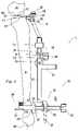
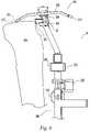
- FIG. 4is a side plan view of the resection guide of FIGS. 1-3 assembled with an optional illustrative femoral cut guide and positioned on a bone;
- FIG. 6is a side plan view of the upper portion of the resection guide of FIGS. 1-3 assembled with an optional illustrative tibial stylus and positioned on a bone.
- the inferior most portion of the femur in extensionis the femoral condyle and the superior most portion of the tibia is the proximal tibial surface.
- proximal and distalare referred to as proximal and lower portions are referred to as distal.
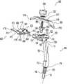
- the tibial cut guide 100( FIG. 1 ) includes a head 102 having an anterior aspect 101 , a posterior aspect 103 , and a proximal aspect 105 .
- the head 102includes a guide surface in the form of a cut slot 104 extending through the head from the anterior aspect 101 to the posterior aspect 103 for guiding a blade to cut the tibia.
- the guide surfacemay take other forms including open planar surfaces, line contact bearing surfaces, and other suitable guide surfaces.
- a support arm 106extends distally from the head 102 from a proximal end 108 adjacent the head 102 to a distal end 110 spaced from the head 102 .
- the head 102 and support arm 106may be formed separately or as an integral piece as shown in the illustrative embodiment.
- the distal end 110 of the support armis aligned along a vertical axis 111 and includes a bearing portion 112 having a non-circular cross section that connects to the support assembly 200 ( FIG. 2 ).
- the non-circular cross sectionprevents rotation of the tibial cut guide 100 relative to the support assembly while permitting axial translation for height adjustment.
- the distal end 110 of the support armfurther includes a mounting post 114 having a proximal threaded proximal portion 116 and a distal smooth portion 118 .
- the threaded portion 116is received by the support assembly 200 ( FIG.
- the tibial cut guide 100includes one or more fixation holes 120 for receiving pins, screws, or other suitable fixation members to anchor the tibial cut guide 100 to the tibia prior to cutting the tibia.
- the fixation holes 120may be provided at any suitable location on the tibial cut guide 100 as long as they anchor the tibial cut guide 100 securely.
- the fixation holes 120are located just below the cut slot 104 and extend through the head 102 from the anterior aspect 101 to the posterior aspect 103 . The forces tending to move the cut guide 100 in use are caused by pressure from a cutter against the edges of the cut slot 104 .
- Placement of the fixation holes 120 close to the cut slot 104minimizes the moment arm over which the forces act and thus provides maximum stability. Placement of the fixation holes 120 close to the cut slot 104 also reduces the overall incision length required to resect the tibia as it permits fixation members to be placed in the same incision through which the bone resection takes place. This is especially useful in a minimally invasive surgical approach since it avoids having to lengthen the incision or create separate percutaneous punctures.
- the tibial cut guide 100further includes a femoral cut guide engagement portion in the form of a dovetail slot 122 formed mediolaterally on the proximal aspect 105 of the head 102 to receive dovetail rails from the femoral cut guide 400 in medial/lateral sliding arrangement.
- a portion 123 of the anterior side of the dovetail slotis relieved to ease attachment and detachment of the cut guide 400 as will be discussed more fully below.
- the illustrative embodimenthas depicted the head 102 with a dovetail slot 122 , the slot and rail arrangement may be reversed or a different attachment mechanism may be provided for connecting the optional femoral cut guide 400 .
- the tibial cut guide 100further includes a depth stylus engagement portion in the form of an axial bore 124 formed in the proximal aspect 105 of the head 102 for receiving a mounting post 504 on the tibial depth setting stylus 500 .
- a depth stylus engagement portionin the form of an axial bore 124 formed in the proximal aspect 105 of the head 102 for receiving a mounting post 504 on the tibial depth setting stylus 500 .
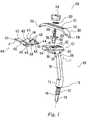
- the support assembly 200( FIG. 2 ) includes a resection guide base 202 having a proximal end 204 , a distal end 206 and an axis 208 therebetween.
- a non-circular bore 210 and a round bore 212are aligned along the axis 208 to receive the distal end 110 of the support arm of the tibial cut guide 100 .
- a slot 214is positioned axially between the bores 210 , 212 to receive a fine height adjustment knob 216 having an axial threaded bore 218 .
- the knob 216is free to rotate about the axis 208 within the slot 214 but is prevented from moving up and down along the axis by impingement with the top 220 and bottom 222 of the slot 214 .
- the non-circular bore 210 of the resection guide base 202receives the non-circular bearing portion 112 of the tibial cut guide 100 in axial sliding arrangement.
- the threaded bore 218 of the knob 216receives the threaded portion 116 of the mounting post 114 of the tibial cut guide 100 for positive height control of the tibial cut guide 100 relative to the resection guide base 202 .
- the round bore 212receives the smooth portion 118 of the mounting post 114 of the tibial cut guide 100 for increased side-to-side stability of the tibial cut guide 100 .
- the side of the knob 216extends from the slot 214 to permit rotation of the knob 216 by thumb pressure from a user to move the tibial cut guide 100 axially up-and-down relative to the resection guide base 202 .
- a fixation arm 226projects upwardly from the proximal end 204 of the resection guide base 202 to a terminal end 228 .
- the terminal end 228is offset posteriorly such that the fixation arm 226 lies beside the support arm 106 of the tibial cut guide 100 and the terminal end 228 lies beside the head 102 of the tibial cut guide 100 when they are assembled ( FIG. 5 ).
- the terminal end 228includes one or more fixation holes 230 to receive fixation members for securing the resection guide base 202 to the tibia.
- An elongated platform 232is attached to the resection guide base 202 at its distal end 206 .
- the platform 232extends mediolaterally and includes a sliding attachment portion in the form of a mediolaterally extending dovetail slot 234 for receiving a distal extension rod 236 .
- the distal extension rod 236includes an elongated non-circular shaft 237 for connecting the resection guide base 202 to the ankle clamp assembly ( FIG. 3 ).
- the extension rod 236includes a proximal end 238 , a distal end 240 , and a longitudinal axis 242 extending therebetween.
- Dovetail rails 244are formed at the proximal end 238 and are received by the dovetail slot 234 of the resection guide base 202 to permit mediolateral relative translation between the extension rod 236 and the resection guide base 202 .
- a slot 246extends from the proximal end 238 of the extension rod 236 distally to divide the dovetail rails 244 into two separate leaves 245 to provide a locking mechanism for fixing the relative position of the extension rod 236 and the resection guide base 202 .
- One of the leaves 245includes a threaded through bore 248 for receiving a locking knob 250 .
- the locking knob 250includes a shaft 252 having a threaded portion 254 and an end 256 .
- the locking knob 250is threaded into the threaded bore 248 of one of the leaves 245 until the end 256 of the shaft 252 contacts the opposite leaf 245 . Further tightening of the locking knob 250 causes the leaves 245 to separate such that the dovetail rails 244 expand and grip the dovetail slot 234 to lock the relative position of the extension rod 236 and resection guide base 202 .
- the illustrative embodimenthas been shown with a dovetail slot 234 on the resection guide base 202 and dovetail rails 244 on the extension rod 236 .
- the slot and rail arrangementmay be reversed and/or other suitable connections may be provided to permit mediolateral adjustability.
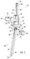
- the ankle clamp assembly 300( FIG. 3 ) includes an ankle clamp base 302 having a proximal end 304 , a distal end 306 , and an axis 308 extending between the proximal and distal ends 304 , 306 .
- An axial non-circular bore 310extends distally from the proximal end 304 to receive the distal extension rod 236 for axial translation.
- the non-circular shape of the bore 310 and extension rod 236prevent the extension rod 236 from rotating relative to the ankle clamp base 302 . Other shapes and mechanisms may also be used to prevent relative rotation of these parts.
- a boss 312extends from the ankle clamp base 302 normal to the axis 308 near the proximal end 304 .
- the boss 312includes a threaded through bore communicating with the axial non-circular bore 310 .
- a vertical, or proximal-distal, coarse adjustment locking knob 314includes a shaft 316 having a threaded portion 318 and an end 320 . The locking knob 314 is threaded into the boss 312 until the end 320 of the shaft 316 lightly contacts the extension rod 236 of the support assembly 200 . Further tightening of the locking knob 314 against the extension rod 236 locks the vertical position of the extension rod 236 relative to the ankle clamp assembly 300 .
- a proximal extension arm 301extends anteriorly from the ankle clamp base 302 and includes a proximal alignment rod hole 303 .
- a distal extension arm 305extends anteriorly from the ankle clamp base 302 and includes a distal alignment rod hole 307 .
- An alignment rod(not shown) may optionally be positioned in the alignment rod holes 303 , 307 to help visualize proper leg positioning such as alignment of the tibial axis with the center of the femoral head.
- the distal end 306 of the ankle clamp base 302is shaped into a distally directed pointer 322 to aid in aligning the ankle clamp assembly axis 308 with the center of a patients ankle.
- An anteroposterior through bore 324 in the distal end 306receives an ankle clamp mounting post 326 for anteroposterior adjustment of the distal end 306 .
- the bore 324is keyed, for example with flat sides as shown, to prevent rotation of the mounting post 326 within the bore 324 .
- the mounting post 326includes a shaft having a cross sectional shape corresponding to the bore 324 and extending from an anterior end 328 to a posterior end 330 .
- a mediolateral extending dovetail rail 332is attached to the posterior end 330 of the mounting post 326 .
- a threaded bore 334extends through the mounting post 326 from the anterior end 328 to the posterior end 330 and on through the dovetail rail 332 .
- An ankle clamp 340includes a base 342 having a dovetail slot 344 extending between opposite sides 346 , 348 of the base 342 for receiving the dovetail rail 332 of the mounting post 326 to permit mediolateral translation of the ankle clamp relative to the mounting post 326 .
- a curved arm 350 having an attachment end 352 and a gripping end 354attaches to each end 346 , 348 of the clamp base 342 with a pivot pin 356 .
- a coil spring 358biases each arm 350 inwardly toward the other.
- the ankle clamp 340may be translated anteriorly and posteriorly by sliding the mounting post 326 in the bore 324 .
- a threaded through bore 360 in the distal end 306 of the ankle clamp base 302communicates with the bore 324 and receives an anterior/posterior (A/P) locking knob 362 .
- the A/P locking knob 362includes a shaft 364 having a threaded portion 366 and an end 368 . The locking knob 362 is threaded into the threaded bore 360 until the end 368 of the shaft 364 lightly contacts the mounting post 326 .
- the ankle clamp 340may be translated mediolaterally by sliding the dovetail slot 344 over the dovetail rail 332 .
- the threaded bore 334 of the mounting post 326receives a medial/lateral (ML) locking knob 370 .
- the M/L locking knob 370includes a shaft 372 having a threaded portion 374 and an end 376 .
- the locking knob 370is threaded into the threaded bore 334 until the end 376 of the shaft 372 lightly contacts the dovetail slot 344 of the ankle clamp 340 . Further tightening of the locking knob 370 against the dovetail slot 344 locks the M/L position of the ankle clamp 340 relative to the ankle clamp base 302 .
- FIGS. 1 , 4 , and 5An illustrative optional modular femoral cut guide 400 is depicted in FIGS. 1 , 4 , and 5 .
- the cut guide 400includes a body 402 having a proximal aspect 404 , a distal aspect 406 , an anterior aspect 408 , a posterior aspect 410 , and sides 412 , 414 .
- the cut guide 400includes a guide surface in the form of a cut slot 416 extending through the cut guide 400 from the anterior aspect 408 to the posterior aspect 410 between the sides 412 , 414 for guiding a blade to cut the femur.
- the guide surfacemay take other forms including open planar surfaces, line contact bearing surfaces, and other suitable guide surfaces.
- a femoral reference paddle 411extends from the posterior aspect 410 of the body 402 at a predetermined spacing distally of the cut slot 416 .
- the paddle 411includes a top surface 413 that may be abutted against the femoral condyle to position the cut slot 416 to remove a predetermined amount of bone from the femoral condyle or alternatively to space the tibial cut slot 104 a predetermined distance from the femoral condyle.
- the paddle 411tapers posteriorly to a thin tip 415 to facilitate insertion into the joint space between the tibia and femur.
- the paddle 411may be permanently attached (as shown) or modular (not shown).
- a modular paddle 411may be provided to ease assembly and insertion of the adjustable resection guide 10 into the surgical wound.
- a modular paddle 411also may be removed after the cut depth is set to permit the knee to be flexed while the cut guide 400 remains in place.
- a modular paddle 411also permits omitting the paddle 411 in cases where the cut depth is set in another manner such as by referencing the tibia.
- a permanently attached paddle 411may be formed as an integral part of the cut guide 400 , welded to the cut guide, or attached in another suitable way.
- a modular paddle 411may be bolted onto the cut guide 400 , snapped in, carried in a slot, or otherwise attached to the cut guide 400 .
- one or more additional slotsmay be provided at a predetermined spacing distal to the cut slot 416 and extending from the anterior aspect to the posterior aspect.
- the paddle 411may be inserted through the second slot from the anterior aspect 408 to the posterior aspect 410 .
- An attachment member in the form of a dovetail rail 418projects from the distal aspect 406 of the cut guide 400 and extends mediolaterally along the distal aspect 406 .
- the dovetail rail 418is received by the dovetail slot 122 of the tibial cut guide head 102 for mediolateral translation of the femoral cut guide 400 relative to the tibial cut guide 100 .
- the dovetail engagementmaintains the angle and spacing between the cutting guide surfaces of the femoral and tibial cut guides 400 , 100 constant while permitting mediolateral translation.
- the dovetail rail 418extends mediolaterally a distance less than the distance between the sides 412 , 414 of the femoral cut guide 400 and the dovetail slot 122 extends only part way across the proximal aspect of the tibial cut guide head 102 to facilitate mounting the femoral cut guide 400 on the tibial cut guide 100 without requiring extreme relative mediolateral positioning of the cut guides 100 , 400 .
- the relieved portion 123 of the dovetail slot 122further facilitates mounting the femoral cut guide 400 .
- the dovetail rail 418is positioned to just clear the side of the dovetail slot 122 adjacent the relieved portion 123 .
- the mediolateral width of the positioned cut guides 100 , 400is much less than the combined widths of the individual cut guides 100 , 400 and much less than would be the width of the positioned cut guides 100 , 400 if the dovetail rail and slot 418 , 122 extended across the full width of the cut guides 400 , 100 and/or if the relieved portion 123 was not provided.
- This arrangementpermits the femoral cut guide 400 to be mounted on the tibial cut guide 100 within the confines of a narrow incision such as the incision used in a minimally invasive approach to knee surgery.
- the femoral cut guide 400is translated posteriorly until the dovetail rail 418 engages the dovetail slot 122 opposite the relieved portion 123 .
- the femoral cut guide 400is translated mediolaterally to engage the dovetail slot 122 adjacent the relieved portion 123 .
- the dovetail membersmay be reversed or other attachment mechanisms may be used.
- the femoral cut guide 400attached to the tibial cut guide 100 , the femoral and tibial cut slots 416 , 104 are positioned to guide cutters to remove a portion of the femur and tibia to create a predetermined gap for receiving an implant.
- Fixation holes 420receive pins, screws, or other fixation members to attach the femoral cut guide at a desired location on the femur.
- FIGS. 1 and 6An illustrative optional tibial depth setting stylus 500 is depicted in FIGS. 1 and 6 .
- the stylus 500includes a mounting base 502 .
- a mounting post 504extends distally from the mounting base 502 and includes a ball detent 505 for secure attachment of the stylus 500 to the tibial cut guide 100 .
- a threaded post 506extends proximally from the mounting base 502 .
- a reference arm 508includes a body 510 having a longitudinal slot 512 and opposite first and second reference tips 514 , 516 . The first and second tips 514 , 516 are offset different distances distally from the body 510 .
- the reference arm slot 512receives the mounting base threaded post 506 and the reference arm 508 is secured to the mounting base 502 with a nut 518 and a washer 520 .
- the stylus 500is mounted on the tibial cut guide 100 by inserting the mounting post 504 into the axial bore 124 formed in the head 102 of the tibial cut guide 100 .
- the ball detent 505is biased outwardly by a captured spring (not shown) such that as the mounting post 504 is inserted, the ball detent 505 is forced back into the mounting post 504 .
- the ball detent 505aligns with the cut slot 104 , the ball detent 505 is biased into engagement with the slot 104 to secure the stylus 500 in a predetermined axial spacing from the cut slot 104 .
- the first and second stylus tips 514 , 516are positioned at predetermined axial distances from the cut slot 104 .
- the cut slot 104may be positioned at two different predetermined cut depths to guide a cutter to remove different amounts of bone from the proximal tibial surface.
- the above described instrumentspermit a variety of uses. They provide flexibility in mediolateral, anteroposterior, and proximal-distal positioning of the cut guides on the bone. They provide for referencing the proximal tibia and/or femur for establishing resection levels. They further provide for linked cutting of the tibia and femur or separate unlinked cutting of the tibia and femur.
- the multiple mechanisms for mediolateral adjustment of the different portions of the instrumentspermit the instruments to be used in a midline position as in a total condylar knee surgery, in a medial position on a left or right knee in a unicondylar knee surgery, and in a lateral position on a left or right knee in a unicondylar knee surgery.
- the mediolateral adjustment at the anklefacilitates proper alignment of the distal portion of the instrument with the tibial axis.
- the mediolateral adjustment in the support assembly 200permits alignment of the tibial cut guide 100 medially, centrally, or laterally on a left or right knee.
- the mediolateral adjustment between the femoral cut guide 400 and the tibial cut guide 100permits the femoral cut guide 400 to be adjusted mediolaterally independently of the tibial cut guide 100 to optimize femoral cut guide 400 alignment on the femur.
- the instrumentincorporates both coarse and fine height adjustment to allow for rapid and accurate height settings.
- the support assembly 200 extension rod 236may be slid proximal-distally within the ankle clamp assembly 300 for rapid height adjustment and gross positioning of the cut guides 100 , 400 .
- the screw mechanism controlled by the fine height adjustment knob 216may then be used to fine tune the resection levels by positively dialing in the desired height.
- the anteroposterior adjustment of the ankle clamp assembly 300permits accurate positioning of the resection guide 10 parallel to the tibial axis to insure accurate anteroposterior resection slopes.
- the resection levelsare set by referencing a femoral condyle 600 of a femur 602 .
- This techniquewill be best understood by referring to FIGS. 4 and 5 showing the assembled adjustable resection guide 10 including the femoral cut guide 400 .
- the adjustable resection guide 10is positioned adjacent the tibia 604 .
- the arms 350 of the ankle clamp 340are spread open and placed around the ankle 606 .
- the coil springs 358bias the arms to grip the ankle 606 .
- the ankle clamp assembly 300is aligned with the center of the ankle 606 by positioning the pointer 322 over the center of the ankle 606 .
- the dovetail rail 332is slid mediolaterally as necessary within the dovetail slot 344 of the ankle clamp 340 .
- the MIL adjustment knob 370is tightened to extend the end 376 of the shaft 372 and lock the mediolateral adjustment.
- the anteroposterior position of the ankle clamp assembly 300is adjusted so that the ankle clamp base 302 is parallel to the tibial axis 608 .
- the A/P adjustment knob 362is then tightened to lock the anteroposterior adjustment.
- the tibial cut guide 100 and support assembly 200are adjusted to bring the tibial cut guide 100 into rough alignment with the approximate tibial resection level.
- This rough settingis locked by tightening the coarse adjustment knob 314 .
- the mediolateral position of the tibial cut guide 100 and support assemblyis adjusted by sliding the dovetail slot 234 of the support assembly 200 over the dovetail rail 244 of the extension rod 236 .
- the mediolateral positionis locked by tightening the M/L adjustment knob 250 .
- the support assembly 200is now secured to the tibia by driving fixation members through the fixation holes 230 .
- the fixation membersmay be positioned within the incision made to expose the joint.
- the support assembly 200 and ankle clamp assembly 300are now aligned and well fixed to the tibia 604 to provide a stable platform for subsequent instrument positioning.
- the femoral cut guide 400is mounted on the tibial cut guide 100 by inserting the paddle 411 in the joint space between the femur 602 and tibia 604 and positioning the dovetail rail 418 adjacent the relieved portion 123 of the dovetail slot 122 .
- the femoral cut guide 400is translated posteriorly until the dovetail rail 418 engages the dovetail slot 122 opposite the relieved portion 123 .
- the femoral cut guide 400is translated mediolaterally to engage the dovetail slot 122 adjacent the relieved portion 123 .
- the fine height adjustment knob 216is rotated to move the femoral cut guide 400 and tibial cut guide 100 as a single unit until the top surface 413 of the paddle 411 contacts the femoral condyle 600 with the leg in proper alignment.
- the surgeonhas several surgical options.
- a first optionwould be to fix both cut guides 100 , 400 in place and cut both the femur 602 and the tibia 604 with the knee in extension.
- the tibial cut guide 100is fixed in place by inserting fixation members through the fixation holes 120 in the tibial cut guide 100 .
- the femoral cut guide 400is adjusted mediolaterally by sliding the dovetail rail 418 in the dovetail slot 122 until the desired mediolateral position of the cut guide is reached.
- the femoral cut guide 400is then fixed in place by inserting fixation members through the fixation holes 420 in the femoral cut guide 400 .
- a cutteris guided through the tibial and femoral cut slots 104 , 416 to remove portions of the tibia 604 and femur 602 .
- a second optionwould be to fix both cut guides 100 , 400 and cut the femur 602 with the knee in extension.
- the femoral cut guide 400is removed by removing the fixation members and sliding the femoral cut guide 400 until the dovetail rail 418 just clears the relieved portion 123 of the dovetail slot 122 and translating the femoral cut guide 400 anteriorly.
- the kneeis then flexed to a convenient angle and the tibia 604 is cut.
- Both the first and second optionsare linked cuts in that the spacing between the cuts is established with the cut guides joined together in fixed predetermined spaced relationship.
- a third optionwould be to cut either the tibia 604 or femur 602 at this stage and then use another technique to cut the other bone.
- the tibial cut guidemay be secured to the tibia 604 and the proximal tibial surface 610 may be resected.
- the adjustable resection guide 10may then be removed and the femur 602 may be cut using another technique such as using spacer blocks as is known in the art. All three of these options rely on referencing the femoral condyle 600 to set the resection height for the femoral and/or tibial cuts.
- the resection levelis established by referencing the proximal tibial surface 610 .
- This techniquewill be best understood by referring to FIG. 6 showing the assembled adjustable resection guide 10 including the tibial depth setting stylus 500 . After exposing a portion of the knee joint the adjustable resection guide 10 is positioned adjacent the tibia 604 and the rough mediolateral, anteroposterior, and proximal-distal adjustments are made as described relative to the femoral referencing technique.
- the tibial stylus 500is attached to the tibial cut guide 100 by snapping the mounting post 504 into the bore 124 in the tibial cut guide 100 .
- the desired amount of tibial resectionis established by positioning the appropriate tip 514 , 516 of the reference arm 508 over the proximal tibial surface 610 .
- the fine height adjustment knob 216is rotated to move the stylus 500 and tibial cut guide 100 as a single unit until one of the tips 514 , 516 contacts the proximal tibial surface 610 .
- the tibial cut guide 100is now positioned to remove a predetermined amount of bone.
- the tibial cut guide 100is secured to the tibia 604 by inserting fixation members through the fixation holes 120 and the proximal tibial surface 610 is resected by guiding a cutter through the tibial cut slot 104 .
- the femoral cut guide 400may be attached to the tibial cut guide 100 to set the femoral resection height. In this case, the cuts would be linked and based on tibial referencing. Alternatively, the femoral cut may be made using another technique such as using spacer guides.
Landscapes
- Health & Medical Sciences (AREA)
- Life Sciences & Earth Sciences (AREA)
- Surgery (AREA)
- Dentistry (AREA)
- Biomedical Technology (AREA)
- Oral & Maxillofacial Surgery (AREA)
- Nuclear Medicine, Radiotherapy & Molecular Imaging (AREA)
- Physical Education & Sports Medicine (AREA)
- Orthopedic Medicine & Surgery (AREA)
- Engineering & Computer Science (AREA)
- Transplantation (AREA)
- Heart & Thoracic Surgery (AREA)
- Medical Informatics (AREA)
- Molecular Biology (AREA)
- Animal Behavior & Ethology (AREA)
- General Health & Medical Sciences (AREA)
- Public Health (AREA)
- Veterinary Medicine (AREA)
- Surgical Instruments (AREA)
Abstract
Description
Claims (21)
Priority Applications (2)
| Application Number | Priority Date | Filing Date | Title |
|---|---|---|---|
| US10/746,385US7641661B2 (en) | 2003-12-26 | 2003-12-26 | Adjustable resection guide |
| US11/034,118US7335206B2 (en) | 2003-12-26 | 2005-01-12 | Adjustable resection guide |
Applications Claiming Priority (1)
| Application Number | Priority Date | Filing Date | Title |
|---|---|---|---|
| US10/746,385US7641661B2 (en) | 2003-12-26 | 2003-12-26 | Adjustable resection guide |
Related Child Applications (1)
| Application Number | Title | Priority Date | Filing Date |
|---|---|---|---|
| US11/034,118Continuation-In-PartUS7335206B2 (en) | 2003-12-26 | 2005-01-12 | Adjustable resection guide |
Publications (2)
| Publication Number | Publication Date |
|---|---|
| US20050143746A1 US20050143746A1 (en) | 2005-06-30 |
| US7641661B2true US7641661B2 (en) | 2010-01-05 |
Family
ID=34700635
Family Applications (1)
| Application Number | Title | Priority Date | Filing Date |
|---|---|---|---|
| US10/746,385Expired - Fee RelatedUS7641661B2 (en) | 2003-12-26 | 2003-12-26 | Adjustable resection guide |
Country Status (1)
| Country | Link |
|---|---|
| US (1) | US7641661B2 (en) |
Cited By (11)
| Publication number | Priority date | Publication date | Assignee | Title |
|---|---|---|---|---|
| US8546456B2 (en) | 2008-07-25 | 2013-10-01 | Smith & Nephew, Inc. | Fracture fixation systems |
| US8672946B2 (en) | 2011-02-11 | 2014-03-18 | Biomet Manfacturing, LLC | Method and apparatus for performing knee arthroplasty |
| US8758354B2 (en) | 2010-10-22 | 2014-06-24 | Zimmer, Inc. | Flexible attachment for an extramedullary surgical instrument |
| US8974459B1 (en) | 2010-05-21 | 2015-03-10 | Howmedica Osteonics Corp. | Natural alignment knee instruments |
| US9078674B2 (en)* | 2007-09-21 | 2015-07-14 | Depuy (Ireland) | Adjustable surgical instrument |
| US20150305754A1 (en)* | 2003-01-15 | 2015-10-29 | Biomet Manufacturing, Llc | Instrumentation For Knee Resection |
| US9610168B2 (en) | 2014-05-12 | 2017-04-04 | Integra Lifesciences Corporation | Total ankle replacement prosthesis |
| US20170319216A1 (en)* | 2016-05-05 | 2017-11-09 | Adam I. Harris | Cutting block apparatus and method of total knee arthroplasty |
| US20190076155A1 (en)* | 2016-03-16 | 2019-03-14 | Medacta International Sa | Instrument for bone resection |
| US20220233332A1 (en)* | 2018-12-13 | 2022-07-28 | Paragon 28, Inc. | Joint replacement alignment guides, systems and methods of use and assembly |
| US11666346B2 (en) | 2007-03-23 | 2023-06-06 | Xiros Limited | Surgical templates |
Families Citing this family (23)
| Publication number | Priority date | Publication date | Assignee | Title |
|---|---|---|---|---|
| US7094241B2 (en) | 2002-11-27 | 2006-08-22 | Zimmer Technology, Inc. | Method and apparatus for achieving correct limb alignment in unicondylar knee arthroplasty |
| JP4231813B2 (en)* | 2003-05-06 | 2009-03-04 | ツィマー ゲーエムベーハー | Traction equipment |
| US8167888B2 (en)* | 2004-08-06 | 2012-05-01 | Zimmer Technology, Inc. | Tibial spacer blocks and femoral cutting guide |
| US7601154B2 (en)* | 2005-04-18 | 2009-10-13 | Uni-Knee, Llc | Unicondylar knee instrument system |
| US7780671B2 (en) | 2006-01-23 | 2010-08-24 | Zimmer Technology, Inc. | Bone resection apparatus and method for knee surgery |
| US7938833B2 (en)* | 2006-11-14 | 2011-05-10 | Howmedica Osteonics Corp. | Adjustable resection guide |
| US20090018544A1 (en)* | 2007-07-13 | 2009-01-15 | Zimmer, Inc. | Method and apparatus for soft tissue balancing |
| US8372080B2 (en)* | 2008-08-26 | 2013-02-12 | Zimmer, Inc. | Trans-cut slot adjustment mechanism |
| KR101973101B1 (en) | 2009-05-29 | 2019-04-26 | 스미스 앤드 네퓨, 인크. | Methods and apparatus for performing knee arthroplasty |
| US8828013B2 (en)* | 2009-11-02 | 2014-09-09 | Synvasive Technology, Inc. | Bone positioning device and method |
| WO2011053332A1 (en)* | 2009-11-02 | 2011-05-05 | Synvasive Technology, Inc. | Knee arthroplasty apparatus and method |
| US9095352B2 (en) | 2009-11-02 | 2015-08-04 | Synvasive Technology, Inc. | Bone positioning device and method |
| US9386993B2 (en) | 2011-09-29 | 2016-07-12 | Biomet Manufacturing, Llc | Patient-specific femoroacetabular impingement instruments and methods |
| US9138237B2 (en)* | 2011-10-13 | 2015-09-22 | Arthrex, Inc. | Total joint instrumentation and method for use |
| EP2775966B1 (en) | 2011-10-24 | 2015-09-16 | Synvasive Technology, Inc. | Knee balancing systems |
| CN104955421A (en) | 2012-10-18 | 2015-09-30 | 史密夫和内修有限公司 | Alignment devices and methods |
| US9974588B2 (en)* | 2012-12-27 | 2018-05-22 | Wright Medical Technology, Inc. | Ankle replacement system and method |
| CN103654924A (en)* | 2013-12-13 | 2014-03-26 | 中国人民解放军第三军医大学第二附属医院 | Tibia cutting device based on ankle joint planar ultrasonic guidance positioning |
| FR3024027B1 (en)* | 2014-07-24 | 2021-05-07 | One Ortho | SURGICAL DEVICE TO ASSIST THE PLACEMENT OF AN ORTHOPEDIC IMPLANT BETWEEN TWO BONES OF A PATIENT JOINT |
| US10485553B2 (en)* | 2016-09-29 | 2019-11-26 | Biomet Manufacturing, Llc | Knee resection and gap balancing instruments and techniques |
| KR102157480B1 (en)* | 2018-07-10 | 2020-09-21 | 주식회사 코렌텍 | Tibia Extramedullary(EM) Alignment Telescopic Assembly |
| US10729453B2 (en)* | 2018-08-22 | 2020-08-04 | Wright Medical Technology, Inc. | Guidance system for hallux valgus correction |
| US20230372121A1 (en)* | 2022-05-20 | 2023-11-23 | Steensen Orthopedic Systems, LLC | Tibial dual stylus instrument having wide convex stylus tips and components thereof |
Citations (128)
| Publication number | Priority date | Publication date | Assignee | Title |
|---|---|---|---|---|
| US2697433A (en) | 1951-12-04 | 1954-12-21 | Max A Zehnder | Device for accurately positioning and guiding guide wires used in the nailing of thefemoral neck |
| US3532088A (en) | 1966-02-23 | 1970-10-06 | Bio Analytical Labor Inc | Speculum instrument |
| US4349018A (en) | 1980-12-29 | 1982-09-14 | Chambers Gary R | Osteotomy apparatus |
| EP0104732A1 (en) | 1982-09-10 | 1984-04-04 | Queen's University At Kingston | Orthopedic bone cutting device |
| US4457307A (en) | 1982-08-20 | 1984-07-03 | Stillwell William T | Bone cutting device for total knee replacement |
| US4524766A (en)* | 1982-01-07 | 1985-06-25 | Petersen Thomas D | Surgical knee alignment method and system |
| US4566448A (en) | 1983-03-07 | 1986-01-28 | Rohr Jr William L | Ligament tensor and distal femoral resector guide |
| US4567886A (en) | 1983-01-06 | 1986-02-04 | Petersen Thomas D | Flexion spacer guide for fitting a knee prosthesis |
| US4574794A (en) | 1984-06-01 | 1986-03-11 | Queen's University At Kingston | Orthopaedic bone cutting jig and alignment device |
| US4646729A (en) | 1982-02-18 | 1987-03-03 | Howmedica, Inc. | Prosthetic knee implantation |
| US4738253A (en) | 1981-12-31 | 1988-04-19 | Biomedical Engineering Trust | Guides for inclined surgical cuts or resections |
| US4759350A (en) | 1986-10-17 | 1988-07-26 | Dunn Harold K | Instruments for shaping distal femoral and proximal tibial surfaces |
| US4825857A (en) | 1982-02-18 | 1989-05-02 | Howmedica, Inc. | Prosthetic knee implantation |
| US4841975A (en)* | 1987-04-15 | 1989-06-27 | Cemax, Inc. | Preoperative planning of bone cuts and joint replacement using radiant energy scan imaging |
| US4938762A (en) | 1987-12-16 | 1990-07-03 | Protek Ag | Reference system for implantation of condylar total knee prostheses |
| US4952213A (en) | 1989-02-03 | 1990-08-28 | Boehringer Mannheim Corporation | Tibial cutting guide |
| US5002547A (en) | 1987-02-07 | 1991-03-26 | Pfizer Hospital Products Group, Inc. | Apparatus for knee prosthesis |
| US5007936A (en) | 1988-02-18 | 1991-04-16 | Cemax, Inc. | Surgical method for hip joint replacement |
| US5116338A (en) | 1988-02-03 | 1992-05-26 | Pfizer Hospital Products Group, Inc. | Apparatus for knee prosthesis |
| US5122144A (en) | 1989-09-26 | 1992-06-16 | Kirschner Medical Corporation | Method and instrumentation for unicompartmental total knee arthroplasty |
| US5213112A (en) | 1992-01-29 | 1993-05-25 | Pfizer Hospital Products Group, Inc. | Tension meter for orthopedic surgery |
| US5230338A (en) | 1987-11-10 | 1993-07-27 | Allen George S | Interactive image-guided surgical system for displaying images corresponding to the placement of a surgical tool or the like |
| US5234433A (en) | 1989-09-26 | 1993-08-10 | Kirschner Medical Corporation | Method and instrumentation for unicompartmental total knee arthroplasty |
| US5251127A (en) | 1988-02-01 | 1993-10-05 | Faro Medical Technologies Inc. | Computer-aided surgery apparatus |
| US5275603A (en) | 1992-02-20 | 1994-01-04 | Wright Medical Technology, Inc. | Rotationally and angularly adjustable tibial cutting guide and method of use |
| US5305203A (en) | 1988-02-01 | 1994-04-19 | Faro Medical Technologies Inc. | Computer-aided surgery apparatus |
| US5306276A (en)* | 1991-12-10 | 1994-04-26 | Zimmer, Inc. | Tibial resector guide |
| US5342368A (en) | 1992-07-08 | 1994-08-30 | Petersen Thomas D | Intramedullary universal proximal tibial resector guide |
| US5344423A (en) | 1992-02-06 | 1994-09-06 | Zimmer, Inc. | Apparatus and method for milling bone |
| US5364402A (en) | 1993-07-29 | 1994-11-15 | Intermedics Orthopedics, Inc. | Tibial spacer saw guide |
| US5364401A (en) | 1992-10-08 | 1994-11-15 | Wright Medical Technology, Inc. | External alignment system for preparing a femur for an implant |
| US5368552A (en) | 1993-07-13 | 1994-11-29 | Rocky Mountain Prosthetics Orthotics | Orthotic hip brace |
| US5451228A (en) | 1993-09-14 | 1995-09-19 | Zimmer, Inc. | Tibial resector guide |
| US5458645A (en) | 1992-04-03 | 1995-10-17 | Bertin; Kim C. | Method for resecting the knee using a resection guide and provisional prosthetic component |
| US5474559A (en) | 1993-07-06 | 1995-12-12 | Zimmer, Inc. | Femoral milling instrumentation for use in total knee arthroplasty with optional cutting guide attachment |
| US5484446A (en) | 1994-06-27 | 1996-01-16 | Zimmer, Inc. | Alignment guide for use in orthopaedic surgery |
| EP0709061A1 (en) | 1994-10-27 | 1996-05-01 | Merck Biomaterial France | Femoral ancillary instrumentation for implanting a unicompartmental knee prosthesis |
| US5514143A (en) | 1991-11-27 | 1996-05-07 | Apogee Medical Products, Inc. | Apparatus and method for use during surgery |
| US5514139A (en) | 1994-09-02 | 1996-05-07 | Hudson Surgical Design, Inc. | Method and apparatus for femoral resection |
| US5527316A (en) | 1994-02-23 | 1996-06-18 | Stone; Kevin T. | Surgical reamer |
| US5540696A (en) | 1995-01-06 | 1996-07-30 | Zimmer, Inc. | Instrumentation for use in orthopaedic surgery |
| US5551429A (en) | 1993-02-12 | 1996-09-03 | Fitzpatrick; J. Michael | Method for relating the data of an image space to physical space |
| US5562674A (en) | 1995-02-27 | 1996-10-08 | Zimmer, Inc. | Intramedullary rod with guide member locator |
| US5593411A (en) | 1995-03-13 | 1997-01-14 | Zimmer, Inc. | Orthopaedic milling guide for milling intersecting planes |
| US5597379A (en) | 1994-09-02 | 1997-01-28 | Hudson Surgical Design, Inc. | Method and apparatus for femoral resection alignment |
| US5601563A (en) | 1995-08-25 | 1997-02-11 | Zimmer, Inc. | Orthopaedic milling template with attachable cutting guide |
| US5611802A (en) | 1995-02-14 | 1997-03-18 | Samuelson; Kent M. | Method and apparatus for resecting bone |
| US5628750A (en) | 1995-06-30 | 1997-05-13 | U.S. Medical Products, Inc. | Tibial resection guide alignment apparatus and method |
| US5643272A (en) | 1994-09-02 | 1997-07-01 | Hudson Surgical Design, Inc. | Method and apparatus for tibial resection |
| US5649928A (en) | 1994-07-08 | 1997-07-22 | Eska Medical Gmbh & Co. | Device for determining resection surfaces of femur and tibia in preparation for implantation of total knee endoprosthesis |
| US5681320A (en) | 1991-12-13 | 1997-10-28 | Mcguire; David A. | Bone-cutting guide |
| US5681316A (en) | 1996-08-22 | 1997-10-28 | Johnson & Johnson Professional, Inc. | Tibial resection guide |
| US5682886A (en) | 1995-12-26 | 1997-11-04 | Musculographics Inc | Computer-assisted surgical system |
| US5683397A (en) | 1995-02-15 | 1997-11-04 | Smith & Nephew, Inc. | Distal femoral cutting guide apparatus for use in knee joint replacement surgery |
| US5704941A (en) | 1995-11-03 | 1998-01-06 | Osteonics Corp. | Tibial preparation apparatus and method |
| US5743915A (en) | 1993-07-06 | 1998-04-28 | Zimmer, Inc. | Femoral milling instrumentation for use in total knee arthoroplasty with optional cutting guide attachment |
| US5755803A (en) | 1994-09-02 | 1998-05-26 | Hudson Surgical Design | Prosthetic implant |
| US5776201A (en) | 1995-10-02 | 1998-07-07 | Johnson & Johnson Professional, Inc. | Modular femoral trial system |
| US5788700A (en)* | 1996-10-30 | 1998-08-04 | Osteonics Corp. | Apparatus and method for the alignment of a total knee prosthesis |
| US5800438A (en) | 1995-10-23 | 1998-09-01 | Finsbury (Instruments) Limited | Surgical tool |
| US5810827A (en) | 1994-09-02 | 1998-09-22 | Hudson Surgical Design, Inc. | Method and apparatus for bony material removal |
| US5824085A (en) | 1996-09-30 | 1998-10-20 | Integrated Surgical Systems, Inc. | System and method for cavity generation for surgical planning and initial placement of a bone prosthesis |
| US5860980A (en) | 1997-09-15 | 1999-01-19 | Axelson, Jr.; Stuart L. | Surgical apparatus for use in total knee arthroplasty and surgical methods for using said apparatus |
| US5904691A (en) | 1996-09-30 | 1999-05-18 | Picker International, Inc. | Trackable guide block |
| US5911723A (en) | 1996-05-28 | 1999-06-15 | Howmedice International Inc. | Surgical apparatus |
| US5921992A (en) | 1997-04-11 | 1999-07-13 | Radionics, Inc. | Method and system for frameless tool calibration |
| FR2776176A1 (en) | 1998-03-20 | 1999-09-24 | Aesculap Sa | Cutter guide positioner for preparing bones for fitting knee prosthesis |
| US5995738A (en) | 1997-02-21 | 1999-11-30 | Carnegie Mellon University | Apparatus and method for facilitating the implantation of artificial components in joints |
| US6033415A (en) | 1998-09-14 | 2000-03-07 | Integrated Surgical Systems | System and method for performing image directed robotic orthopaedic procedures without a fiducial reference system |
| US6051016A (en) | 1999-03-29 | 2000-04-18 | Instrumed, Inc. | System and method of controlling pressure in a surgical tourniquet |
| US6077270A (en) | 1995-05-31 | 2000-06-20 | Katz; Lawrence | Method and apparatus for locating bone cuts at the distal condylar femur region to receive a femoral prothesis and to coordinate tibial and patellar resection and replacement with femoral resection and replacement |
| US6090114A (en)* | 1997-02-10 | 2000-07-18 | Stryker Howmedica Osteonics Corp. | Tibial plateau resection guide |
| US6167145A (en) | 1996-03-29 | 2000-12-26 | Surgical Navigation Technologies, Inc. | Bone navigation system |
| US6267762B1 (en) | 1999-04-01 | 2001-07-31 | Aesculap | Device for the positioning of a proximal extremity of a tibia against a cutting guide including an adjusting handle |
| US6285902B1 (en) | 1999-02-10 | 2001-09-04 | Surgical Insights, Inc. | Computer assisted targeting device for use in orthopaedic surgery |
| WO2001066021A1 (en) | 2000-03-10 | 2001-09-13 | Smith & Nephew, Inc | A method of arthroplasty on a knee joint and apparatus for use in same |
| US6296646B1 (en) | 2000-06-29 | 2001-10-02 | Richard V. Williamson | Instruments and methods for use in performing knee surgery |
| WO2001085038A1 (en) | 2000-04-27 | 2001-11-15 | Finsbury (Development) Limited | Tenser for performing a knee replacement operation |
| US6396939B1 (en) | 1998-05-28 | 2002-05-28 | Orthosoft Inc. | Method and system for segmentation of medical images |
| DE20202615U1 (en) | 2002-02-20 | 2002-06-06 | Aesculap AG & Co. KG, 78532 Tuttlingen | Template for guiding a surgical processing tool |
| US20020068942A1 (en) | 2000-09-26 | 2002-06-06 | Timo Neubauer | Device, system and method for determining the positon of an incision block |
| US6402762B2 (en) | 1999-10-28 | 2002-06-11 | Surgical Navigation Technologies, Inc. | System for translation of electromagnetic and optical localization systems |
| FR2819168A1 (en) | 2001-01-09 | 2002-07-12 | Fedan N B N V | Apparatus for implanting knee prosthesis comprises positioning block fixed at end of femur which has two guides, into which mask fits with transverse slots through which tool can be introduced to carry out resection of femur head |
| US6430434B1 (en) | 1998-12-14 | 2002-08-06 | Integrated Surgical Systems, Inc. | Method for determining the location and orientation of a bone for computer-assisted orthopedic procedures using intraoperatively attached markers |
| US6450978B1 (en) | 1998-05-28 | 2002-09-17 | Orthosoft, Inc. | Interactive computer-assisted surgical system and method thereof |
| US20020133164A1 (en) | 2000-06-29 | 2002-09-19 | Williamson Richard V. | Instruments and methods for use in performing knee surgery |
| US20020133162A1 (en) | 2001-03-17 | 2002-09-19 | Axelson Stuart L. | Tools used in performing femoral and tibial resection in knee surgery |
| US20020133160A1 (en) | 2001-02-28 | 2002-09-19 | Axelson Stuart L. | Systems used in performing femoral and tibial resection in knee surgery |
| US20020133163A1 (en) | 2001-02-28 | 2002-09-19 | Axelson Stuart L. | Apparatus used in performing femoral and tibial resection in knee surgery |
| US6477400B1 (en) | 1998-08-20 | 2002-11-05 | Sofamor Danek Holdings, Inc. | Fluoroscopic image guided orthopaedic surgery system with intraoperative registration |
| US6490467B1 (en) | 1990-10-19 | 2002-12-03 | Surgical Navigation Technologies, Inc. | Surgical navigation systems including reference and localization frames |
| US20020198530A1 (en) | 2001-06-20 | 2002-12-26 | Sanford Adam H. | Method and apparatus for resecting a distal femur and a proximal tibia in preparation for implanting a partial knee prosthesis |
| US6503254B2 (en) | 1995-11-02 | 2003-01-07 | Medidea, Llc | Apparatus and method for preparing box cuts in a distal femur with a cutting guide attached to an intramedullary stem |
| US6514259B2 (en) | 2001-02-02 | 2003-02-04 | Carnegie Mellon University | Probe and associated system and method for facilitating planar osteotomy during arthoplasty |
| US20030069591A1 (en) | 2001-02-27 | 2003-04-10 | Carson Christopher Patrick | Computer assisted knee arthroplasty instrumentation, systems, and processes |
| US20030069585A1 (en) | 2001-10-10 | 2003-04-10 | Axelson Stuart L. | Methods and tools for femoral resection in knee surgery |
| US6554837B1 (en) | 1998-06-29 | 2003-04-29 | Plus Endoprothetik Ag | Device and method for inserting a prosthetic knee |
| US20030100906A1 (en) | 2001-11-28 | 2003-05-29 | Rosa Richard A. | Methods of minimally invasive unicompartmental knee replacement |
| US6575980B1 (en) | 1997-01-28 | 2003-06-10 | New York Society For The Ruptured And Crippled Maintaining The Hospital For Special Surgery | Method and apparatus for femoral resection |
| DE20303498U1 (en) | 2003-02-26 | 2003-07-03 | Aesculap AG & Co. KG, 78532 Tuttlingen | Surgical adjusting and holding device for tool guiding arrangement, in particular for performance of operation at femur or tibia |
| US6595997B2 (en) | 2001-02-28 | 2003-07-22 | Howmedica Osteonics Corp. | Methods used in performing femoral and tibial resection in knee surgery |
| US20030225413A1 (en) | 2002-06-04 | 2003-12-04 | Adam Sanford | Two-piece cut block for minimally invasive surgical procedure |
| US20030233149A1 (en) | 2002-06-18 | 2003-12-18 | Robert Hodorek | Porous unicondylar knee |
| US6695848B2 (en) | 1994-09-02 | 2004-02-24 | Hudson Surgical Design, Inc. | Methods for femoral and tibial resection |
| US20040039396A1 (en) | 2002-08-23 | 2004-02-26 | Orthosoft Inc. | Universal positioning block |
| WO2004017842A2 (en) | 2002-08-23 | 2004-03-04 | Orthosoft Inc. | Surgical universal positioning block and tool guide |
| US6712824B2 (en) | 2001-06-25 | 2004-03-30 | Aesculap Ag & Co Kg | Apparatus for positioning the angle of a bone cutting guide |
| US20040102785A1 (en) | 2002-11-27 | 2004-05-27 | Hodorek Robert A. | Method and apparatus for achieving correct limb alignment in unicondylar knee arthroplasty |
| US20040122305A1 (en) | 2002-12-20 | 2004-06-24 | Grimm James E. | Surgical instrument and method of positioning same |
| US20040153062A1 (en) | 2003-02-04 | 2004-08-05 | Mcginley Shawn E. | Surgical navigation instrument useful in marking anatomical structures |
| US20040152955A1 (en) | 2003-02-04 | 2004-08-05 | Mcginley Shawn E. | Guidance system for rotary surgical instrument |
| US20040249387A1 (en) | 2003-04-25 | 2004-12-09 | Francisco Faoro | Apparatus for the preparation of a femoral condyle |
| US6859661B2 (en) | 2001-01-25 | 2005-02-22 | Finsbury (Development) Limited | Surgical system for use in the course of a knee replacement operation |
| US20050070910A1 (en) | 2001-08-10 | 2005-03-31 | Greg Keene | Tibial resection guide |
| US20050182415A1 (en) | 2003-12-26 | 2005-08-18 | Zimmer Technology, Inc. | Adjustable resection guide |
| US6932823B2 (en) | 2003-06-24 | 2005-08-23 | Zimmer Technology, Inc. | Detachable support arm for surgical navigation system reference array |
| US20050203528A1 (en) | 2002-08-23 | 2005-09-15 | Pierre Couture | Surgical universal positioning block and tool guide |
| US20050203541A1 (en) | 2004-03-03 | 2005-09-15 | Zimmer Technology, Inc. | Tibial sizer |
| EP1579812A1 (en) | 2004-03-24 | 2005-09-28 | Zimmer GmbH | Device for positioning a cutting guide for tibial resection |
| US20060030855A1 (en) | 2004-03-08 | 2006-02-09 | Haines Timothy G | Methods and apparatus for improved profile based resection |
| US20060036257A1 (en) | 2004-08-06 | 2006-02-16 | Zimmer Technology, Inc. | Tibial spacer blocks and femoral cutting guide |
| US7029477B2 (en) | 2002-12-20 | 2006-04-18 | Zimmer Technology, Inc. | Surgical instrument and positioning method |
| US20060189998A1 (en) | 2005-02-08 | 2006-08-24 | Rasmussen G L | Guide assembly for guiding cuts to a femur and tibia during a knee arthroplasty |
| US20060195111A1 (en) | 2005-01-25 | 2006-08-31 | Orthosoft Inc. | Universal positioning block assembly |
| US20060217734A1 (en) | 2005-03-09 | 2006-09-28 | Zimmer Technology, Inc. | Femoral resection guide apparatus and method |
| US7201755B2 (en) | 2003-04-25 | 2007-04-10 | Zimmer Gmbh | Apparatus for the preparation of a femoral condyle |
| US7235080B2 (en) | 2003-02-20 | 2007-06-26 | Zimmer Technology, Inc. | Femoral reference tibial cut guide |
| US20070173854A1 (en) | 2006-01-23 | 2007-07-26 | Berger Richard A | Bone resection apparatus and method for knee surgery |
Family Cites Families (1)
| Publication number | Priority date | Publication date | Assignee | Title |
|---|---|---|---|---|
| JPH11333778A (en)* | 1998-05-29 | 1999-12-07 | Daihen Corp | Carrying robot device |
- 2003
- 2003-12-26USUS10/746,385patent/US7641661B2/ennot_activeExpired - Fee Related
Patent Citations (152)
| Publication number | Priority date | Publication date | Assignee | Title |
|---|---|---|---|---|
| US2697433A (en) | 1951-12-04 | 1954-12-21 | Max A Zehnder | Device for accurately positioning and guiding guide wires used in the nailing of thefemoral neck |
| US3532088A (en) | 1966-02-23 | 1970-10-06 | Bio Analytical Labor Inc | Speculum instrument |
| US4349018A (en) | 1980-12-29 | 1982-09-14 | Chambers Gary R | Osteotomy apparatus |
| US4738253A (en) | 1981-12-31 | 1988-04-19 | Biomedical Engineering Trust | Guides for inclined surgical cuts or resections |
| US4524766A (en)* | 1982-01-07 | 1985-06-25 | Petersen Thomas D | Surgical knee alignment method and system |
| US4646729A (en) | 1982-02-18 | 1987-03-03 | Howmedica, Inc. | Prosthetic knee implantation |
| US4825857A (en) | 1982-02-18 | 1989-05-02 | Howmedica, Inc. | Prosthetic knee implantation |
| US4457307A (en) | 1982-08-20 | 1984-07-03 | Stillwell William T | Bone cutting device for total knee replacement |
| EP0104732A1 (en) | 1982-09-10 | 1984-04-04 | Queen's University At Kingston | Orthopedic bone cutting device |
| US4567886A (en) | 1983-01-06 | 1986-02-04 | Petersen Thomas D | Flexion spacer guide for fitting a knee prosthesis |
| US4566448A (en) | 1983-03-07 | 1986-01-28 | Rohr Jr William L | Ligament tensor and distal femoral resector guide |
| US4574794A (en) | 1984-06-01 | 1986-03-11 | Queen's University At Kingston | Orthopaedic bone cutting jig and alignment device |
| US4759350A (en) | 1986-10-17 | 1988-07-26 | Dunn Harold K | Instruments for shaping distal femoral and proximal tibial surfaces |
| US5002547A (en) | 1987-02-07 | 1991-03-26 | Pfizer Hospital Products Group, Inc. | Apparatus for knee prosthesis |
| US4841975A (en)* | 1987-04-15 | 1989-06-27 | Cemax, Inc. | Preoperative planning of bone cuts and joint replacement using radiant energy scan imaging |
| US5230338A (en) | 1987-11-10 | 1993-07-27 | Allen George S | Interactive image-guided surgical system for displaying images corresponding to the placement of a surgical tool or the like |
| US4938762A (en) | 1987-12-16 | 1990-07-03 | Protek Ag | Reference system for implantation of condylar total knee prostheses |
| US5305203A (en) | 1988-02-01 | 1994-04-19 | Faro Medical Technologies Inc. | Computer-aided surgery apparatus |
| US5251127A (en) | 1988-02-01 | 1993-10-05 | Faro Medical Technologies Inc. | Computer-aided surgery apparatus |
| US5116338A (en) | 1988-02-03 | 1992-05-26 | Pfizer Hospital Products Group, Inc. | Apparatus for knee prosthesis |
| US5007936A (en) | 1988-02-18 | 1991-04-16 | Cemax, Inc. | Surgical method for hip joint replacement |
| US4952213A (en) | 1989-02-03 | 1990-08-28 | Boehringer Mannheim Corporation | Tibial cutting guide |
| US5234433A (en) | 1989-09-26 | 1993-08-10 | Kirschner Medical Corporation | Method and instrumentation for unicompartmental total knee arthroplasty |
| US5122144A (en) | 1989-09-26 | 1992-06-16 | Kirschner Medical Corporation | Method and instrumentation for unicompartmental total knee arthroplasty |
| US6490467B1 (en) | 1990-10-19 | 2002-12-03 | Surgical Navigation Technologies, Inc. | Surgical navigation systems including reference and localization frames |
| US5514143A (en) | 1991-11-27 | 1996-05-07 | Apogee Medical Products, Inc. | Apparatus and method for use during surgery |
| US5306276A (en)* | 1991-12-10 | 1994-04-26 | Zimmer, Inc. | Tibial resector guide |
| US5445640A (en)* | 1991-12-10 | 1995-08-29 | Zimmer, Inc. | Tibial resector guide |
| US5681320A (en) | 1991-12-13 | 1997-10-28 | Mcguire; David A. | Bone-cutting guide |
| US5213112A (en) | 1992-01-29 | 1993-05-25 | Pfizer Hospital Products Group, Inc. | Tension meter for orthopedic surgery |
| US5344423A (en) | 1992-02-06 | 1994-09-06 | Zimmer, Inc. | Apparatus and method for milling bone |
| US5486180A (en) | 1992-02-06 | 1996-01-23 | Zimmer, Inc. | Apparatus for milling bone |
| US5342367A (en) | 1992-02-20 | 1994-08-30 | Wright Medical Technology, Inc. | Rotationally and angularly adjustable tibial cutting guide and method of use |
| US5275603A (en) | 1992-02-20 | 1994-01-04 | Wright Medical Technology, Inc. | Rotationally and angularly adjustable tibial cutting guide and method of use |
| US5458645A (en) | 1992-04-03 | 1995-10-17 | Bertin; Kim C. | Method for resecting the knee using a resection guide and provisional prosthetic component |
| US5342368A (en) | 1992-07-08 | 1994-08-30 | Petersen Thomas D | Intramedullary universal proximal tibial resector guide |
| US5364401A (en) | 1992-10-08 | 1994-11-15 | Wright Medical Technology, Inc. | External alignment system for preparing a femur for an implant |
| US5551429A (en) | 1993-02-12 | 1996-09-03 | Fitzpatrick; J. Michael | Method for relating the data of an image space to physical space |
| US5743915A (en) | 1993-07-06 | 1998-04-28 | Zimmer, Inc. | Femoral milling instrumentation for use in total knee arthoroplasty with optional cutting guide attachment |
| US5474559A (en) | 1993-07-06 | 1995-12-12 | Zimmer, Inc. | Femoral milling instrumentation for use in total knee arthroplasty with optional cutting guide attachment |
| US5368552A (en) | 1993-07-13 | 1994-11-29 | Rocky Mountain Prosthetics Orthotics | Orthotic hip brace |
| US5364402A (en) | 1993-07-29 | 1994-11-15 | Intermedics Orthopedics, Inc. | Tibial spacer saw guide |
| US5451228A (en) | 1993-09-14 | 1995-09-19 | Zimmer, Inc. | Tibial resector guide |
| US5527316A (en) | 1994-02-23 | 1996-06-18 | Stone; Kevin T. | Surgical reamer |
| US5484446A (en) | 1994-06-27 | 1996-01-16 | Zimmer, Inc. | Alignment guide for use in orthopaedic surgery |
| US5649928A (en) | 1994-07-08 | 1997-07-22 | Eska Medical Gmbh & Co. | Device for determining resection surfaces of femur and tibia in preparation for implantation of total knee endoprosthesis |
| US5597379A (en) | 1994-09-02 | 1997-01-28 | Hudson Surgical Design, Inc. | Method and apparatus for femoral resection alignment |
| US6695848B2 (en) | 1994-09-02 | 2004-02-24 | Hudson Surgical Design, Inc. | Methods for femoral and tibial resection |
| US6056754A (en) | 1994-09-02 | 2000-05-02 | Hudson Surgical Design, Inc. | Method and apparatus for patella resection and guide handle |
| US5879354A (en) | 1994-09-02 | 1999-03-09 | Hudson Surgical Design, Inc. | Prosthetic implant |
| US5643272A (en) | 1994-09-02 | 1997-07-01 | Hudson Surgical Design, Inc. | Method and apparatus for tibial resection |
| US6197064B1 (en) | 1994-09-02 | 2001-03-06 | Hudson Surgical Design, Inc. | Prosthetic implant |
| US5514139A (en) | 1994-09-02 | 1996-05-07 | Hudson Surgical Design, Inc. | Method and apparatus for femoral resection |
| US5810827A (en) | 1994-09-02 | 1998-09-22 | Hudson Surgical Design, Inc. | Method and apparatus for bony material removal |
| US5755803A (en) | 1994-09-02 | 1998-05-26 | Hudson Surgical Design | Prosthetic implant |
| EP0709061A1 (en) | 1994-10-27 | 1996-05-01 | Merck Biomaterial France | Femoral ancillary instrumentation for implanting a unicompartmental knee prosthesis |
| US5540696A (en) | 1995-01-06 | 1996-07-30 | Zimmer, Inc. | Instrumentation for use in orthopaedic surgery |
| US5688280A (en) | 1995-01-06 | 1997-11-18 | Bristol-Myers Squibb Co. | Instrumentation for use in orthopaedic surgery |
| US5611802A (en) | 1995-02-14 | 1997-03-18 | Samuelson; Kent M. | Method and apparatus for resecting bone |
| US5683397A (en) | 1995-02-15 | 1997-11-04 | Smith & Nephew, Inc. | Distal femoral cutting guide apparatus for use in knee joint replacement surgery |
| US5562674A (en) | 1995-02-27 | 1996-10-08 | Zimmer, Inc. | Intramedullary rod with guide member locator |
| US5593411A (en) | 1995-03-13 | 1997-01-14 | Zimmer, Inc. | Orthopaedic milling guide for milling intersecting planes |
| US6077270A (en) | 1995-05-31 | 2000-06-20 | Katz; Lawrence | Method and apparatus for locating bone cuts at the distal condylar femur region to receive a femoral prothesis and to coordinate tibial and patellar resection and replacement with femoral resection and replacement |
| US5628750A (en) | 1995-06-30 | 1997-05-13 | U.S. Medical Products, Inc. | Tibial resection guide alignment apparatus and method |
| US5601563A (en) | 1995-08-25 | 1997-02-11 | Zimmer, Inc. | Orthopaedic milling template with attachable cutting guide |
| US5776201A (en) | 1995-10-02 | 1998-07-07 | Johnson & Johnson Professional, Inc. | Modular femoral trial system |
| US5800438A (en) | 1995-10-23 | 1998-09-01 | Finsbury (Instruments) Limited | Surgical tool |
| US6503254B2 (en) | 1995-11-02 | 2003-01-07 | Medidea, Llc | Apparatus and method for preparing box cuts in a distal femur with a cutting guide attached to an intramedullary stem |
| US5704941A (en) | 1995-11-03 | 1998-01-06 | Osteonics Corp. | Tibial preparation apparatus and method |
| US5682886A (en) | 1995-12-26 | 1997-11-04 | Musculographics Inc | Computer-assisted surgical system |
| US5871018A (en) | 1995-12-26 | 1999-02-16 | Delp; Scott L. | Computer-assisted surgical method |
| US6167145A (en) | 1996-03-29 | 2000-12-26 | Surgical Navigation Technologies, Inc. | Bone navigation system |
| US5911723A (en) | 1996-05-28 | 1999-06-15 | Howmedice International Inc. | Surgical apparatus |
| EP0809969B1 (en) | 1996-05-28 | 2002-10-30 | Howmedica International S. De R.L. | Bone cutting guide |
| US5681316A (en) | 1996-08-22 | 1997-10-28 | Johnson & Johnson Professional, Inc. | Tibial resection guide |
| US5824085A (en) | 1996-09-30 | 1998-10-20 | Integrated Surgical Systems, Inc. | System and method for cavity generation for surgical planning and initial placement of a bone prosthesis |
| US5904691A (en) | 1996-09-30 | 1999-05-18 | Picker International, Inc. | Trackable guide block |
| US5788700A (en)* | 1996-10-30 | 1998-08-04 | Osteonics Corp. | Apparatus and method for the alignment of a total knee prosthesis |
| EP0839501B1 (en) | 1996-10-30 | 2003-03-12 | Osteonics Corp. | Apparatus and method for the alignment of a total knee prosthesis |
| US6575980B1 (en) | 1997-01-28 | 2003-06-10 | New York Society For The Ruptured And Crippled Maintaining The Hospital For Special Surgery | Method and apparatus for femoral resection |
| US6090114A (en)* | 1997-02-10 | 2000-07-18 | Stryker Howmedica Osteonics Corp. | Tibial plateau resection guide |
| US6002859A (en) | 1997-02-21 | 1999-12-14 | Carnegie Mellon University | Apparatus and method facilitating the implantation of artificial components in joints |
| US5995738A (en) | 1997-02-21 | 1999-11-30 | Carnegie Mellon University | Apparatus and method for facilitating the implantation of artificial components in joints |
| US5921992A (en) | 1997-04-11 | 1999-07-13 | Radionics, Inc. | Method and system for frameless tool calibration |
| US5860980A (en) | 1997-09-15 | 1999-01-19 | Axelson, Jr.; Stuart L. | Surgical apparatus for use in total knee arthroplasty and surgical methods for using said apparatus |
| FR2776176A1 (en) | 1998-03-20 | 1999-09-24 | Aesculap Sa | Cutter guide positioner for preparing bones for fitting knee prosthesis |
| US6450978B1 (en) | 1998-05-28 | 2002-09-17 | Orthosoft, Inc. | Interactive computer-assisted surgical system and method thereof |
| US6396939B1 (en) | 1998-05-28 | 2002-05-28 | Orthosoft Inc. | Method and system for segmentation of medical images |
| US6554837B1 (en) | 1998-06-29 | 2003-04-29 | Plus Endoprothetik Ag | Device and method for inserting a prosthetic knee |
| US6477400B1 (en) | 1998-08-20 | 2002-11-05 | Sofamor Danek Holdings, Inc. | Fluoroscopic image guided orthopaedic surgery system with intraoperative registration |
| US6033415A (en) | 1998-09-14 | 2000-03-07 | Integrated Surgical Systems | System and method for performing image directed robotic orthopaedic procedures without a fiducial reference system |
| US6430434B1 (en) | 1998-12-14 | 2002-08-06 | Integrated Surgical Systems, Inc. | Method for determining the location and orientation of a bone for computer-assisted orthopedic procedures using intraoperatively attached markers |
| US6285902B1 (en) | 1999-02-10 | 2001-09-04 | Surgical Insights, Inc. | Computer assisted targeting device for use in orthopaedic surgery |
| US6051016A (en) | 1999-03-29 | 2000-04-18 | Instrumed, Inc. | System and method of controlling pressure in a surgical tourniquet |
| US6475228B1 (en) | 1999-03-29 | 2002-11-05 | Instrumed, Inc. | System and method of controlling pressure in a surgical tourniquet |
| US6267762B1 (en) | 1999-04-01 | 2001-07-31 | Aesculap | Device for the positioning of a proximal extremity of a tibia against a cutting guide including an adjusting handle |
| US6402762B2 (en) | 1999-10-28 | 2002-06-11 | Surgical Navigation Technologies, Inc. | System for translation of electromagnetic and optical localization systems |
| US7371240B2 (en)* | 2000-03-10 | 2008-05-13 | Smith & Nephew, Inc. | Method of arthroplasty on a knee joint and apparatus for use in same |
| WO2001066021A1 (en) | 2000-03-10 | 2001-09-13 | Smith & Nephew, Inc | A method of arthroplasty on a knee joint and apparatus for use in same |
| WO2001085038A1 (en) | 2000-04-27 | 2001-11-15 | Finsbury (Development) Limited | Tenser for performing a knee replacement operation |
| US20020133164A1 (en) | 2000-06-29 | 2002-09-19 | Williamson Richard V. | Instruments and methods for use in performing knee surgery |
| US6478799B1 (en) | 2000-06-29 | 2002-11-12 | Richard V. Williamson | Instruments and methods for use in performing knee surgery |
| US6296646B1 (en) | 2000-06-29 | 2001-10-02 | Richard V. Williamson | Instruments and methods for use in performing knee surgery |
| US20020068942A1 (en) | 2000-09-26 | 2002-06-06 | Timo Neubauer | Device, system and method for determining the positon of an incision block |
| US6551325B2 (en) | 2000-09-26 | 2003-04-22 | Brainlab Ag | Device, system and method for determining the position of an incision block |
| FR2819168A1 (en) | 2001-01-09 | 2002-07-12 | Fedan N B N V | Apparatus for implanting knee prosthesis comprises positioning block fixed at end of femur which has two guides, into which mask fits with transverse slots through which tool can be introduced to carry out resection of femur head |
| US6859661B2 (en) | 2001-01-25 | 2005-02-22 | Finsbury (Development) Limited | Surgical system for use in the course of a knee replacement operation |
| US6514259B2 (en) | 2001-02-02 | 2003-02-04 | Carnegie Mellon University | Probe and associated system and method for facilitating planar osteotomy during arthoplasty |
| US20030069591A1 (en) | 2001-02-27 | 2003-04-10 | Carson Christopher Patrick | Computer assisted knee arthroplasty instrumentation, systems, and processes |
| US6595997B2 (en) | 2001-02-28 | 2003-07-22 | Howmedica Osteonics Corp. | Methods used in performing femoral and tibial resection in knee surgery |
| US20020133160A1 (en) | 2001-02-28 | 2002-09-19 | Axelson Stuart L. | Systems used in performing femoral and tibial resection in knee surgery |
| US20020133163A1 (en) | 2001-02-28 | 2002-09-19 | Axelson Stuart L. | Apparatus used in performing femoral and tibial resection in knee surgery |
| US6685711B2 (en) | 2001-02-28 | 2004-02-03 | Howmedica Osteonics Corp. | Apparatus used in performing femoral and tibial resection in knee surgery |
| US20020133162A1 (en) | 2001-03-17 | 2002-09-19 | Axelson Stuart L. | Tools used in performing femoral and tibial resection in knee surgery |
| US6632225B2 (en) | 2001-06-20 | 2003-10-14 | Zimmer, Inc. | Method and apparatus for resecting a distal femur and a proximal tibia in preparation for implanting a partial knee prosthesis |
| US20030216741A1 (en) | 2001-06-20 | 2003-11-20 | Sanford Adam H. | Method and apparatus for resecting a distal femur and a proximal tibia in preparation for implementing a partial knee prosthesis |
| US20020198530A1 (en) | 2001-06-20 | 2002-12-26 | Sanford Adam H. | Method and apparatus for resecting a distal femur and a proximal tibia in preparation for implanting a partial knee prosthesis |
| US6712824B2 (en) | 2001-06-25 | 2004-03-30 | Aesculap Ag & Co Kg | Apparatus for positioning the angle of a bone cutting guide |
| US20050070910A1 (en) | 2001-08-10 | 2005-03-31 | Greg Keene | Tibial resection guide |
| US20030069585A1 (en) | 2001-10-10 | 2003-04-10 | Axelson Stuart L. | Methods and tools for femoral resection in knee surgery |
| US20030100906A1 (en) | 2001-11-28 | 2003-05-29 | Rosa Richard A. | Methods of minimally invasive unicompartmental knee replacement |
| DE20202615U1 (en) | 2002-02-20 | 2002-06-06 | Aesculap AG & Co. KG, 78532 Tuttlingen | Template for guiding a surgical processing tool |
| US20030225413A1 (en) | 2002-06-04 | 2003-12-04 | Adam Sanford | Two-piece cut block for minimally invasive surgical procedure |
| US20030233149A1 (en) | 2002-06-18 | 2003-12-18 | Robert Hodorek | Porous unicondylar knee |
| US20040039396A1 (en) | 2002-08-23 | 2004-02-26 | Orthosoft Inc. | Universal positioning block |
| US20050203528A1 (en) | 2002-08-23 | 2005-09-15 | Pierre Couture | Surgical universal positioning block and tool guide |
| WO2004017842A2 (en) | 2002-08-23 | 2004-03-04 | Orthosoft Inc. | Surgical universal positioning block and tool guide |
| WO2004019792A1 (en) | 2002-08-27 | 2004-03-11 | Smith & Nephew, Inc. | Computer assisted knee arthroplasty instrumentation, system, and process |
| EP1424042B1 (en) | 2002-11-27 | 2007-03-21 | Zimmer Technology, Inc. | Apparatus for achieving correct limb alignment in unicondylar knee arthroplasty |
| US7094241B2 (en) | 2002-11-27 | 2006-08-22 | Zimmer Technology, Inc. | Method and apparatus for achieving correct limb alignment in unicondylar knee arthroplasty |
| US20060247647A1 (en) | 2002-11-27 | 2006-11-02 | Zimmer Technology, Inc. | Method and apparatus for achieving correct limb alignment in unicondylar knee arthroplasty |
| US20040102785A1 (en) | 2002-11-27 | 2004-05-27 | Hodorek Robert A. | Method and apparatus for achieving correct limb alignment in unicondylar knee arthroplasty |
| US20060149276A1 (en) | 2002-12-20 | 2006-07-06 | Grimm James E | Surgical instrument and positioning method |
| US7029477B2 (en) | 2002-12-20 | 2006-04-18 | Zimmer Technology, Inc. | Surgical instrument and positioning method |
| US20040122305A1 (en) | 2002-12-20 | 2004-06-24 | Grimm James E. | Surgical instrument and method of positioning same |
| US20040152955A1 (en) | 2003-02-04 | 2004-08-05 | Mcginley Shawn E. | Guidance system for rotary surgical instrument |
| US20040153062A1 (en) | 2003-02-04 | 2004-08-05 | Mcginley Shawn E. | Surgical navigation instrument useful in marking anatomical structures |
| US7235080B2 (en) | 2003-02-20 | 2007-06-26 | Zimmer Technology, Inc. | Femoral reference tibial cut guide |
| DE20303498U1 (en) | 2003-02-26 | 2003-07-03 | Aesculap AG & Co. KG, 78532 Tuttlingen | Surgical adjusting and holding device for tool guiding arrangement, in particular for performance of operation at femur or tibia |
| US20040249387A1 (en) | 2003-04-25 | 2004-12-09 | Francisco Faoro | Apparatus for the preparation of a femoral condyle |
| US7201755B2 (en) | 2003-04-25 | 2007-04-10 | Zimmer Gmbh | Apparatus for the preparation of a femoral condyle |
| US6932823B2 (en) | 2003-06-24 | 2005-08-23 | Zimmer Technology, Inc. | Detachable support arm for surgical navigation system reference array |
| US20050182415A1 (en) | 2003-12-26 | 2005-08-18 | Zimmer Technology, Inc. | Adjustable resection guide |
| US7335206B2 (en) | 2003-12-26 | 2008-02-26 | Zimmer Technology, Inc. | Adjustable resection guide |
| US20050203541A1 (en) | 2004-03-03 | 2005-09-15 | Zimmer Technology, Inc. | Tibial sizer |
| US20060030855A1 (en) | 2004-03-08 | 2006-02-09 | Haines Timothy G | Methods and apparatus for improved profile based resection |
| EP1579812A1 (en) | 2004-03-24 | 2005-09-28 | Zimmer GmbH | Device for positioning a cutting guide for tibial resection |
| US20060036257A1 (en) | 2004-08-06 | 2006-02-16 | Zimmer Technology, Inc. | Tibial spacer blocks and femoral cutting guide |
| US20060195111A1 (en) | 2005-01-25 | 2006-08-31 | Orthosoft Inc. | Universal positioning block assembly |
| US20060189998A1 (en) | 2005-02-08 | 2006-08-24 | Rasmussen G L | Guide assembly for guiding cuts to a femur and tibia during a knee arthroplasty |
| US20060217734A1 (en) | 2005-03-09 | 2006-09-28 | Zimmer Technology, Inc. | Femoral resection guide apparatus and method |
| US20070173854A1 (en) | 2006-01-23 | 2007-07-26 | Berger Richard A | Bone resection apparatus and method for knee surgery |
Non-Patent Citations (2)
| Title |
|---|
| Zimmer, IM: The M/G(TM) Unicompartmental Knee Minimally Invasive Surgical Technique, 2002. |
| Zimmer, IM: The M/G™ Unicompartmental Knee Minimally Invasive Surgical Technique, 2002. |
Cited By (26)
| Publication number | Priority date | Publication date | Assignee | Title |
|---|---|---|---|---|
| US9693788B2 (en)* | 2003-01-15 | 2017-07-04 | Biomet Manufacturing, Llc | Instrumentation for knee resection |
| US20150305754A1 (en)* | 2003-01-15 | 2015-10-29 | Biomet Manufacturing, Llc | Instrumentation For Knee Resection |
| US11672548B2 (en) | 2007-03-23 | 2023-06-13 | Xiros Limited | Surgical templates |
| US11666346B2 (en) | 2007-03-23 | 2023-06-06 | Xiros Limited | Surgical templates |
| US9078674B2 (en)* | 2007-09-21 | 2015-07-14 | Depuy (Ireland) | Adjustable surgical instrument |
| US8546456B2 (en) | 2008-07-25 | 2013-10-01 | Smith & Nephew, Inc. | Fracture fixation systems |
| US9730740B2 (en) | 2008-07-25 | 2017-08-15 | Smith & Nephew, Inc. | Fracture fixation systems |
| US9855057B2 (en) | 2010-05-21 | 2018-01-02 | Howmedica Osteonics Corp. | Natural alignment knee instruments |
| US9113957B2 (en) | 2010-05-21 | 2015-08-25 | Howmedica Osteonics Corp. | Natural alignment knee instruments |
| US8974459B1 (en) | 2010-05-21 | 2015-03-10 | Howmedica Osteonics Corp. | Natural alignment knee instruments |
| US8758354B2 (en) | 2010-10-22 | 2014-06-24 | Zimmer, Inc. | Flexible attachment for an extramedullary surgical instrument |
| US10349955B2 (en) | 2011-02-11 | 2019-07-16 | Biomet Manufacturing, Llc | Method and apparatus for performing knee arthroplasty |
| US9463032B2 (en) | 2011-02-11 | 2016-10-11 | Biomet Manufacturing, Llc | Method and apparatus for performing knee arthroplasty |
| US8672946B2 (en) | 2011-02-11 | 2014-03-18 | Biomet Manfacturing, LLC | Method and apparatus for performing knee arthroplasty |
| US10653528B2 (en) | 2014-05-12 | 2020-05-19 | Integra Lifesciences Corporation | Total ankle replacement prosthesis |
| US9610168B2 (en) | 2014-05-12 | 2017-04-04 | Integra Lifesciences Corporation | Total ankle replacement prosthesis |
| US11369481B2 (en) | 2014-05-12 | 2022-06-28 | Smith & Nephew, Inc. | Total ankle replacement prosthesis |
| US10166110B2 (en) | 2014-05-12 | 2019-01-01 | Integra Lifesciences Corporation | Total ankle replacement prosthesis |
| US12251315B2 (en) | 2014-05-12 | 2025-03-18 | Smith & Nephew, Inc. | Total ankle replacement prosthesis |
| US20190076155A1 (en)* | 2016-03-16 | 2019-03-14 | Medacta International Sa | Instrument for bone resection |
| US11534178B2 (en) | 2016-03-16 | 2022-12-27 | Medacta International Sa | Instrument for bone resection |
| US10939924B2 (en)* | 2016-03-16 | 2021-03-09 | Medacta International Sa | Instrument for bone resection |
| US10413304B2 (en)* | 2016-05-05 | 2019-09-17 | Adam I. Harris | Cutting block apparatus and method of total knee arthroplasty |
| US11452530B2 (en) | 2016-05-05 | 2022-09-27 | Adam I. Harris | Cutting block apparatus and method of total knee arthroplasty |
| US20170319216A1 (en)* | 2016-05-05 | 2017-11-09 | Adam I. Harris | Cutting block apparatus and method of total knee arthroplasty |
| US20220233332A1 (en)* | 2018-12-13 | 2022-07-28 | Paragon 28, Inc. | Joint replacement alignment guides, systems and methods of use and assembly |
Also Published As
| Publication number | Publication date |
|---|---|
| US20050143746A1 (en) | 2005-06-30 |
Similar Documents
| Publication | Publication Date | Title |
|---|---|---|
| US7641661B2 (en) | Adjustable resection guide | |
| US7335206B2 (en) | Adjustable resection guide | |
| US12156664B2 (en) | Resection guides, sweeping reamers, and methods for use in total ankle replacement | |
| US7282054B2 (en) | Adjustable cut block | |
| US8603095B2 (en) | Apparatuses for femoral and tibial resection | |
| US9066804B2 (en) | Method and apparatus for femoral and tibial resection | |
| US8118811B2 (en) | Apparatus for knee surgery and method of use | |
| US5304181A (en) | Methods and apparatus for arthroscopic prosthetic knee replacement | |
| AU2007232316B2 (en) | Orthopaedic cutting guide instrument | |
| AU784909B2 (en) | Femoral knee saw guide and method | |
| US8062377B2 (en) | Methods and apparatus for knee arthroplasty | |
| US7780671B2 (en) | Bone resection apparatus and method for knee surgery | |
| JP5838181B2 (en) | Devices and methods for distal resection of knee prostheses | |
| GB2576602A (en) | Multifunctional spacer for knee surgery to achieve balanced resection | |
| WO2000071035A1 (en) | Bone resection guide |
Legal Events
| Date | Code | Title | Description |
|---|---|---|---|
| AS | Assignment | Owner name:ZIMMER TECHNOLOGY, INC., ILLINOIS Free format text:ASSIGNMENT OF ASSIGNORS INTEREST;ASSIGNORS:STEFFENSMEIER, SCOTT J.;SANFORD, ADAM H.;REEL/FRAME:014858/0870 Effective date:20031216 | |
| FEPP | Fee payment procedure | Free format text:PAYER NUMBER DE-ASSIGNED (ORIGINAL EVENT CODE: RMPN); ENTITY STATUS OF PATENT OWNER: LARGE ENTITY Free format text:PAYOR NUMBER ASSIGNED (ORIGINAL EVENT CODE: ASPN); ENTITY STATUS OF PATENT OWNER: LARGE ENTITY | |
| STCF | Information on status: patent grant | Free format text:PATENTED CASE | |
| CC | Certificate of correction | ||
| FPAY | Fee payment | Year of fee payment:4 | |
| AS | Assignment | Owner name:ZIMMER, INC., INDIANA Free format text:MERGER;ASSIGNOR:ZIMMER TECHNOLOGY, INC.;REEL/FRAME:035107/0073 Effective date:20121127 | |
| AS | Assignment | Owner name:SMITH & NEPHEW, INC., TENNESSEE Free format text:ASSIGNMENT OF ASSIGNORS INTEREST;ASSIGNORS:ZIMMER BIOMET HOLDINGS, INC.;ZIMMER, INC.;REEL/FRAME:036054/0585 Effective date:20150629 | |
| FPAY | Fee payment | Year of fee payment:8 | |
| FEPP | Fee payment procedure | Free format text:MAINTENANCE FEE REMINDER MAILED (ORIGINAL EVENT CODE: REM.); ENTITY STATUS OF PATENT OWNER: LARGE ENTITY | |
| LAPS | Lapse for failure to pay maintenance fees | Free format text:PATENT EXPIRED FOR FAILURE TO PAY MAINTENANCE FEES (ORIGINAL EVENT CODE: EXP.); ENTITY STATUS OF PATENT OWNER: LARGE ENTITY | |
| STCH | Information on status: patent discontinuation | Free format text:PATENT EXPIRED DUE TO NONPAYMENT OF MAINTENANCE FEES UNDER 37 CFR 1.362 | |
| FP | Lapsed due to failure to pay maintenance fee | Effective date:20220105 |