US7640373B2 - Method and apparatus for channel quality feedback within a communication system - Google Patents
Method and apparatus for channel quality feedback within a communication systemDownload PDFInfo
- Publication number
- US7640373B2 US7640373B2US10/423,243US42324303AUS7640373B2US 7640373 B2US7640373 B2US 7640373B2US 42324303 AUS42324303 AUS 42324303AUS 7640373 B2US7640373 B2US 7640373B2
- Authority
- US
- United States
- Prior art keywords
- channel quality
- request message
- quality report
- report
- remote station
- Prior art date
- Legal status (The legal status is an assumption and is not a legal conclusion. Google has not performed a legal analysis and makes no representation as to the accuracy of the status listed.)
- Expired - Lifetime, expires
Links
Images


Classifications
- H—ELECTRICITY
- H04—ELECTRIC COMMUNICATION TECHNIQUE
- H04L—TRANSMISSION OF DIGITAL INFORMATION, e.g. TELEGRAPHIC COMMUNICATION
- H04L1/00—Arrangements for detecting or preventing errors in the information received
- H04L1/0001—Systems modifying transmission characteristics according to link quality, e.g. power backoff
- H04L1/0009—Systems modifying transmission characteristics according to link quality, e.g. power backoff by adapting the channel coding
- H—ELECTRICITY
- H04—ELECTRIC COMMUNICATION TECHNIQUE
- H04L—TRANSMISSION OF DIGITAL INFORMATION, e.g. TELEGRAPHIC COMMUNICATION
- H04L1/00—Arrangements for detecting or preventing errors in the information received
- H04L1/0001—Systems modifying transmission characteristics according to link quality, e.g. power backoff
- H04L1/0023—Systems modifying transmission characteristics according to link quality, e.g. power backoff characterised by the signalling
- H04L1/0026—Transmission of channel quality indication
- H—ELECTRICITY
- H04—ELECTRIC COMMUNICATION TECHNIQUE
- H04L—TRANSMISSION OF DIGITAL INFORMATION, e.g. TELEGRAPHIC COMMUNICATION
- H04L25/00—Baseband systems
- H04L25/02—Details ; arrangements for supplying electrical power along data transmission lines
- H04L25/0202—Channel estimation
- H04L25/0222—Estimation of channel variability, e.g. coherence bandwidth, coherence time, fading frequency
- H—ELECTRICITY
- H04—ELECTRIC COMMUNICATION TECHNIQUE
- H04L—TRANSMISSION OF DIGITAL INFORMATION, e.g. TELEGRAPHIC COMMUNICATION
- H04L1/00—Arrangements for detecting or preventing errors in the information received
- H04L1/0001—Systems modifying transmission characteristics according to link quality, e.g. power backoff
- H04L1/0002—Systems modifying transmission characteristics according to link quality, e.g. power backoff by adapting the transmission rate
- H04L1/0003—Systems modifying transmission characteristics according to link quality, e.g. power backoff by adapting the transmission rate by switching between different modulation schemes
- H—ELECTRICITY
- H04—ELECTRIC COMMUNICATION TECHNIQUE
- H04L—TRANSMISSION OF DIGITAL INFORMATION, e.g. TELEGRAPHIC COMMUNICATION
- H04L1/00—Arrangements for detecting or preventing errors in the information received
- H04L1/12—Arrangements for detecting or preventing errors in the information received by using return channel
- H04L1/16—Arrangements for detecting or preventing errors in the information received by using return channel in which the return channel carries supervisory signals, e.g. repetition request signals
- H04L1/18—Automatic repetition systems, e.g. Van Duuren systems
- H04L1/1803—Stop-and-wait protocols
- H—ELECTRICITY
- H04—ELECTRIC COMMUNICATION TECHNIQUE
- H04L—TRANSMISSION OF DIGITAL INFORMATION, e.g. TELEGRAPHIC COMMUNICATION
- H04L25/00—Baseband systems
- H04L25/02—Details ; arrangements for supplying electrical power along data transmission lines
- H04L25/03—Shaping networks in transmitter or receiver, e.g. adaptive shaping networks
- H04L25/03006—Arrangements for removing intersymbol interference
- H04L2025/0335—Arrangements for removing intersymbol interference characterised by the type of transmission
- H04L2025/03375—Passband transmission
- H04L2025/03414—Multicarrier
- H—ELECTRICITY
- H04—ELECTRIC COMMUNICATION TECHNIQUE
- H04L—TRANSMISSION OF DIGITAL INFORMATION, e.g. TELEGRAPHIC COMMUNICATION
- H04L25/00—Baseband systems
- H04L25/02—Details ; arrangements for supplying electrical power along data transmission lines
- H04L25/03—Shaping networks in transmitter or receiver, e.g. adaptive shaping networks
- H04L25/03006—Arrangements for removing intersymbol interference
- H04L2025/03777—Arrangements for removing intersymbol interference characterised by the signalling
- H04L2025/03802—Signalling on the reverse channel
- H—ELECTRICITY
- H04—ELECTRIC COMMUNICATION TECHNIQUE
- H04L—TRANSMISSION OF DIGITAL INFORMATION, e.g. TELEGRAPHIC COMMUNICATION
- H04L25/00—Baseband systems
- H04L25/02—Details ; arrangements for supplying electrical power along data transmission lines
- H04L25/0202—Channel estimation
- H04L25/0212—Channel estimation of impulse response
Definitions
- the present inventionrelates generally to communication systems and in particular, to a method and apparatus for channel quality feedback within a communication system.
- Next-generation communication system standardsuse fast adaptive modulation and coding (AMC) combined with multi-user diversity scheduling to provide system capacity improvements for packet data applications.
- AMCfast adaptive modulation and coding
- Such systemstypically use some form of channel quality feedback that briefs the scheduler with regards to the channel conditions of each mobile.
- the scheduleruses the feedback to identify which users are in a constructive fade and then to select the appropriate modulation and coding rate based on the reported channel conditions.
- the feedbackis designed to track fading for low mobility (e.g. 3-30 kmph).
- the feedback rateis 2.4 kbps; a 4-bit channel quality report is sent back every 1.67 ms.
- Such communication systemstypically utilize a dedicated control channel that is established for the duration of a packet call, and the channel quality feedback is transmitted as part of the dedicated control channel.
- the dedicated control channelis typically activated when a user requests a web page and de-activated after a period of inactivity by a pre-defined inactivity timer.
- Current implementationsset the inactivity timers as high as 60 seconds, but in the future it may be set as low as 2-to-5 seconds. Even with the lower numbers, ten to one hundred users may be simultaneously maintaining a dedicated control channel depending on the packet data application being used. Because of this, the aggregate rate of all the feedback channels can be as high as 240 kbps.
- significant gaps between packets existe.g. 200 ms
- most of the mobilesdo not have a single packet queued while they are providing this channel quality feedback. Thus, the majority of the feedback is unnecessary and wastes uplink resources.
- FIG. 1is a block diagram of a communication system in accordance with the preferred embodiment of the present invention.
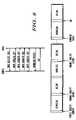
- FIG. 2illustrates a channel quality request message in accordance with the preferred embodiment of the present invention.
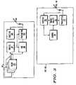
- FIG. 3is a block diagram of a base station and remote station in accordance with the preferred embodiment of the present invention.
- FIG. 4is a flow chart showing operation of the base station of FIG. 1 .
- FIG. 5is a flow chart showing operation of a remote station of FIG. 1
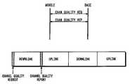
- FIG. 6shows a message sequence diagram for the transmission of a channel quality request message and reception of a channel quality report message.
- FIG. 7illustrates timing advance as part of a channel quality request message.
- FIG. 8illustrates the reception of several uplink channel quality report messages.
- a base stationwill request the transmission of quality information from a particular remote stations only when data is queued to be transmitted to the remote stations. Once a remote station begins the transmission of channel quality information, the transmission of such information continues until the data transmission is successfully delivered to the remote station.
- the base stationreceives the channel quality information and adjusts the modulation and coding of the remote stations accordingly. Where data is transmitted simultaneously to a plurality of remote stations, a set of queues for the multiple remote stations is maintained, and based on queue status, a channel quality request messages is sent to a sub-set of remote stations with data queued.
- the present inventionencompasses a method comprising the steps of determining if data is queued to be sent to a remote station, and based on whether or not data is queued, transmitting a channel quality request message to the remote station, causing the remote station to transmit a channel quality report indicating a perceived channel quality.
- the present inventionadditionally encompasses a method comprising the steps of receiving a channel quality request message from a base station and in response to the channel quality request message, transmitting a channel quality report message to the base station indicating a perceived channel quality, The channel quality report messages are transmitted to the base station until a data packet is successfully received from the base station.
- the present inventionadditionally encompasses a method comprising the steps of determining that data is queued for a plurality of remote stations, transmitting a plurality of channel quality request reports to a first subset of the plurality of remote stations causing the first subset of the plurality of remote stations to transmit a plurality of channel quality reports indicating a perceived channel quality, and based on the plurality of channel quality reports, transmitting queued data to a second subset of the plurality of remote stations.
- the present inventionadditionally encompasses an apparatus comprising a plurality of data queues, logic circuitry determining remote units that have data queued within the plurality of data queues, and a transmitter, transmitting a channel quality request message to the remote station in response to the logic circuitry determining that data is queued for the remote unit, the channel quality request message causing the remote station to transmit a channel quality report indicating a perceived channel quality.
- FIG. 1is a block diagram of communication system 100 in accordance with the preferred embodiment of the present invention.
- communication system 100utilizes a next-generation communication system protocol such as, but not limited to the IEEE 802.20 or a 4 th generation communication system protocol.
- communication system 100comprises base station 101 and mobile, (or remote stations) 102 and 103 .
- base station 101is communicating to remote stations 102 and 103 via downlink communication signal 104
- remote stations 102 and 103are communicating to base station 101 via uplink communication signals 105 and 106 , respectively.
- base station 101may receive channel quality feedback from each mobile. Base station 101 may use this information to select a subset of mobiles with the best channel conditions and adaptively modify a modulation and coding (AMC) for those mobiles in communication with base station 101 . More particularly, with stream-level AMC, the modulation and coding format of a data stream is changed to match the current received signal quality (S/(I+N)). In a system with AMC along with multi-stream transmission, streams with high S/(I+N) are typically assigned higher-order modulations rates (e.g., 64-QAM), with the modulation-order and/or the code rate decreasing as S/(I+N) decreases.
- AMCmodulation and coding
- Each downlink streamis modulated utilizing a modulation scheme that is dependent upon the received signal quality for the stream. For those receivers experiencing high signal-to-noise, modulation schemes such as 16 QAM 64 QAM 256 QAM are utilized, while for those receivers experiencing low signal-to-noise, modulation schemes such as QPSK and BPSK are utilized.
- modulation schemessuch as 16 QAM 64 QAM 256 QAM are utilized, while for those receivers experiencing low signal-to-noise, modulation schemes such as QPSK and BPSK are utilized.
- channel quality reportingis performed by all remote stations within communication system 100 only when requested by base station 101 .
- base station 101will request channel quality information from a particular remote station only when data is queued to be transmitted to the remote station, and based off the received information, base station 101 will determine appropriate AMC parameters for transmission.
- the base station 101may request channel quality from a first subset of remote stations in communication with base station 101 that have data queued. Base station 101 may then select a second subset of remote units to receive data transmissions. This second subset may be based on a variety of factors such as best channel quality condition, the highest priority data or service guarantees (e.g. fairness). Alternatively, the selection criteria may be based on a weighted combination of the above-mentioned factors.
- the AMC parameters for these data transmissionsare then based on the received channel quality information.
- channel quality reportingcontinues by the remote station until the next data packet is successfully received from the base station.
- different reporting schemesmay be utilized.
- the channel quality reportingcontinues by the remote station until no data remains queued to be transmitted to that remote station at the base station.
- the remote unitknows that there is no remaining data queued when it successfully receives a data packet associated with an indicator that a channel quality report message is no longer required.
- the indicatoris typically the queue status transmitted as a last packet indicator.
- the channel quality reportingcontinues by the remote station for a predetermined period of time.
- the channel quality report messagemay take one of several predefined formats. For example:
- Various techniques for reporting the channel qualityinclude, but are not limited to:
- Channel quality report contentscan be quantized channel quality information (such as C/I), or a data rate request, received-signal-strength indicator, modulation and coding rate, modulation and coding scheme index, or the like.
- the receiverchooses between two different formats based on vehicle speed and observed frequency selectivity of the channel. Each format can be sent at a different transmit power level.
- the transmitter that receives the channel quality report messagecan blindly decode the resource assignment and determine which format the receiver used.
- the resources used for the transmissioncan be different sizes for each message. The resource sizes may be the same, perhaps to facilitate blind decoding at the transmitter.
- all formatsuse an Interleaved Frequency Division Multiple Access (IFDMA) uplink (with a fixed Repetition Factor (RPF) for that uplink/downlink split), QPSK modulation, a lowest RPF of 32 to 128 with a fixed 192 bit payload.
- IFDMAInterleaved Frequency Division Multiple Access
- RPFRepetition Factor
- QPSK modulationa lowest RPF of 32 to 128 with a fixed 192 bit payload.
- a CRCis added for reliability.
- the channel quality report messagemay contain a single channel quality value.
- a format with a single measurementis often an average value across the frequency band. It is possible that a single value may have fewer information bits in the message, and can be sent with lower power and achieve the same reliability and lower system interference.
- a first formatdenoted “Average C/I measurement”, contains a non-frequency selective measurement of the channel. It may contain the average channel condition quantized to, for example, 8 bits. This format may be used for high Doppler (velocity) conditions when the channel cannot be accurately tracked over time, when there is too much frequency selectivity in the channel, or when extra frequency selective information would not be useful (flat single path channel).
- the channel quality report messagemay contain multiple channel quality values. In a preferred embodiment, each value may be tied to a different frequency domain support.
- a second format, denoted “Frequency selective measurement”,is required for frequency selective (DSL-like) scheduling/coding method, as known in the art. This method can advantageously improve throughput to a lower velocity (Doppler) user without excessive frequency selectivity in the channel.
- the formatcontains a full frequency domain report of the downlink quality. For example, in an Orthogonal Frequency Division Multiplexed (OFDM) downlink with 768 subcarriers, one 2-bit desired modulation level for each group of 16 subcarriers can be sent (96 bits total). Other methods of source coding (run length coding, etc.) the frequency selective information are also possible, and could allow more bits (say 3 to 4) per frequency bin.
- OFDMOrthogonal Frequency Division Multiplexed
- the channel quality report messagemay contain spatial channel information.
- the channel quality reportmay be a channel sounding waveform.
- the channel sounding waveformis a known waveform received by the transmitter and used to estimate the channel at the transmitter. This method of channel estimation may be useful for both downlink and uplink transmissions in a Time Division Duplex (TDD) system.
- TDDTime Division Duplex
- the channel quality report messagemay also contain additional information to help the transmitter schedule a transmission or the next channel quality request, such as a mobile speed indicator, spatial channel quality indicator, multi-path delay spread detector, etc.
- a spatial channel quality indicatormay be a condition number or reciprocal condition number.
- the additional informationwould help the transmitter determine when it is appropriate to schedule the next channel quality request/report. For example, if the receiver reports an instantaneous channel quality that is far below the average for a low vehicular speed, the base may wait many frames before requesting additional feedback. Alternatively, if a mobile reports high vehicular speed, the base may dispense with additional feedback prior to scheduling a downlink transmission since it is difficult to track the fast fading.
- the channel quality request messagecan be transmitted as known in the art.
- the methodcould use different or no coding, a different modulation, and could be transmitted within a CDMA, TDMA, or other system, as is known in the art.
- the 39 information bits within the channel quality request messageare as follows:
- TIMING ADVANCEindicates that the receiver should initiate a timing advance update procedure.
- the timing advance procedurecan be any procedure known in the art. For example, the receiver could send a timing advance burst and then receive a timing advance update from the transmitter, possibly a 4-bit value of the timing advance in microseconds;
- PERSISTENCEindicates whether more than one channel quality report message should be sent in response to the channel quality request message;
- TIMEOUTindicates the maximum number of channel quality report messages to be sent after a channel quality request (typically 2, 4, 8, or 16, measured from the last successful packet transfer);
- RESOURCE ALLOCATIONindicates which receiver to transmitter link resources should be used for the channel quality report message;
- CRC(beyond the user ID) plus the number of bits in ‘User ID’ is used for cyclic redundancy check to be used to ensure message integrity; and
- TAIL BITSare used within the error correction encoder/decoder.
- the base stationsends the PERSISTENCE field to instruct the remote station to continue transmission of channel quality reports until a downlink packet is delivered successfully.
- the base stationlearns of the successful delivery by receiving the acknowledgment from the remote station.
- the PERSISTENCE fieldinstructs the remote station to continue transmission of channel quality reports until the base station's associated remote-unit specific queue is empty.
- the remote stationwill learn the queue is empty by receiving a last-packet indication with the data transmission or control data associated with the data transmission. Once the last-packet is received successfully and acknowledged (e.g. acknowledgement was sent or negative acknowledgement was not sent), the remote station assumes that the base station's associated remote station specific queue is empty.
- the TIMEOUT fieldis used in conjunction with the PERSISTENCE field to provide alternative criteria for the remote station to stop the transmission of channel quality reports. For example if the TIMEOUT field is set to N, the remote station would continue channel quality reports for no more than N repetitions as in a third embodiment. Consistent with the previous description, a remote station will discontinue channel quality reports when a downlink packet is delivered before the timeout expires.
- the PERSISTENCE fieldinstructs the remote station to continue transmission until the base station's associated remote-unit specific queue is empty.
- an intermediate indicationmay be used to reset the channel quality report timeout. For example, each downlink transmission with the last packet field set to false could be used to reset the channel quality report timeout.
- mobile, or remote stations within communication system 100will not transmit channel quality information unless specifically requested to do so by base station 101 .
- Base station 101will request the transmission of quality information from a particular remote station only when data is queued to be transmitted to the remote station. Once a remote station begins the transmission of channel quality information, the transmission of such information continues until the data transmission is successfully delivered to the remote station.
- Base station 101receives the channel quality information and determines the modulation and coding scheme accordingly.
- a set of queues for the multiple remote stationsis maintained, and based on queue status, channel quality request messages are sent to a first subset of remote stations with data queued.
- This first subsetcould simply be all remote stations with data queued or it can be reduced based on other information, such as the priority associated with the remote stations, channel quality trends determined from past channel quality reports, vehicular speed (e.g. slow, medium, fast) or service guarantees.
- the other informationmay also include knowledge that the base station can only process a maximum number of requests/report messages per frame, or that the base station does not want to get in more messages than can be reasonably scheduled.
- the base stationmay also want channel quality report messages coming in more of a pipelined fashion, especially with embodiments where multiple channel quality messages may be sent in response to a single channel quality request message.
- the base stationthen receives channel quality reports back from the first subset of remote stations indicating a perceived channel quality. Based on the received channel quality reports and other information, the base selects a second subset of remote stations for data transmission. Similar to the selection of the first subset, the other information used for the second subset may include channel quality trends determined from past channel quality reports, vehicular speed or service guarantees. The other information also contains continuing channel quality reports from remote stations that had earlier received a channel quality request.
- the base stationmay determine, based on received channel quality reports and other information, a modulation and coding scheme for each of the remote stations. For remote stations that are not selected to be in the second subset, this modulation and coding scheme would be representative of a modulation and coding scheme that could have been used if that remote unit had been selected. For remote units within the second subset, the queued data is transmitted utilizing the determined modulation and coding scheme.
- a modulation and coding schememay comprise one or more modulation and coding levels. More than one modulation and coding level may be appropriate when the channel quality report message indicates a modulation level for each of a plurality of sub-bands, as might be sent in a “Frequency selective measurement.”
- FIG. 3is a block diagram of base station 101 along with a mobile, or remote station 102 , 103 in accordance with the preferred embodiment of the present invention.
- base station 101comprises control circuitry 301 , a plurality of remote station specific data queues 303 , Adaptive Modulation and Coding (AMC) circuitry 305 , transmitter 307 , and receiver 309 .
- Control circuitry 301is preferably a microprocessor controller such as, but not limited to a Motorola PowerPC.
- Receiver 309 and transmitter 307are preferably standard transmission and reception circuitry that utilizes one of several well known transmission/reception protocols such as, but not limited to IFDMA and OFDM.
- AMC circuitry 305performs modulation and coding of data, changing the modulation and coding to match the current received signal quality.
- Each of the remote station specific queues 303will buffer data for a respective remote-unit within the system.
- the control circuitry 301is coupled to the remote station specific queues 303 so as to learn of the status of these queues being empty or full. Additionally, control circuitry 301 is coupled to receiver 309 in order to receive channel quality reports and downlink acknowledgements, while control circuitry 301 transmits channel quality requests via transmitter 307 .
- Control circuitry 301additionally is coupled to AMC circuitry 305 in order to identify which remote stations will receive data in the current frame and forward channel quality reports.
- AMC circuitry 305is coupled to the remote specific data queues 303 in order to retrieve packets for transmissions.
- AMC circuitry 305is coupled to transmitter 307 to transmit formatted data frames.
- the remote station 102 , 103comprises control circuitry 311 , data queues 313 , transmitter 317 , and receiver 319 .
- Control circuitry 311is preferably a microprocessor controller such as, but not limited to an ARM processor.
- Receiver 319 and transmitter 317are preferably standard transmission and reception circuitry that utilizes one of several well known transmission/reception protocols such as, but not limited to IFDMA and OFDM.
- Channel quality circuitry 315is used to measure the channel quality and may be as simple as a receive signal strength indicator. Alternatively, the channel quality circuitry may be integrated with receiver and report on metrics associated with the demodulation process as is known by those skilled in the art.
- Control circuitry 311is coupled with receiver 319 in order receive channel quality requests and downlink data packets. Control circuitry 311 is coupled with channel quality measurement circuitry 315 in order to measure the channel quality; and coupled to transmitter 317 in order to send channel quality reports and acknowledgements. Channel quality measurement circuitry 315 will be coupled to the antenna to measure the quality of the channel. Operation of base station 101 and remote station 102 , 103 in accordance with the preferred embodiment of the present invention occurs as shown in FIG. 4 and FIG. 5 , respectively.
- FIG. 4is a flow chart illustrating operation of base station 101 without timing advance in accordance with the preferred embodiment of the present invention.
- the logic flowbegins at step 401 where control circuitry 301 determines which remote stations have data queued in their associated remote station specific queues 303 .
- control circuitry 301instructs transmitter 307 to transmit a channel quality request message to a first subset of the remote stations.
- the first subset of remote stationsmay simply be all remote stations with data queued. However, this first subset should be reduced to exclude all remote-units that are known to be persistently transmitting channel quality reports in response to previous channel quality requests to which data transmission has not been completed. Alternatively, the first subset may be further reduced based on a variety of other factors including trends determined from past channel quality reports, vehicular speed or service guarantees.
- receiver 309receives a plurality of channel quality report messages from the remote stations (step 405 ). Note that some of these channel quality reports may represent persistent transmissions that have been solicited during previous frames. As discussed above, the channel quality report messages contain an indication of the perceived channel quality experienced by the remote stations. Based on the channel quality, control circuitry 301 determines a second subset of remote stations for data transmission. This second subset may be those remote stations who have the best channel conditions, the highest priority, or predetermined service guarantees. Furthermore, this second subset may be determined by a weighted function of all factors. For those remote stations, control circuitry 301 determines an appropriate modulation and coding scheme to utilize when transmitting the data to the remote stations (step 409 ).
- steps 409 and 407may be combined so that the AMC level is determined prior to or in conjunction with the selection of the second subset.
- the AMC levelinfluences the quantity of resources (e.g. transmit power and number of symbols) required to communicate the queued data and therefore may limit the size of subset once all available resources are exhausted.
- the queued datais transmitted to the second subset of the plurality of remote stations utilizing the appropriate modulation and coding.
- the second subset of remote stations to have their data transmittedis chosen based on the remote stations' perceived channel condition. More particularly, those remote stations having good perceived channel conditions will have data transmitted to them, while remote stations (if any) perceiving poor channel conditions will not have data transmitted to them. At a later point in time, logic circuitry will repeat the above steps. In many cases the remote stations perceiving poor channel conditions will experience better channel conditions and have their data transmitted to them.
- the second subsetmay be those remote stations who have the highest priority or predetermined service guarantees. Furthermore, this second subset may be determined by a weighted function of all factors.
- base station 101may embed the queue status information with data transmissions. This comprises the transmission of a queue-status bit that will indicate whether the associated data packet is the last data packet in the queue. If not the last packet, then the remote station will assume the remote-specific queue is non-empty following the initial channel quality report request and cause the remote stations to continuously transmit channel quality reports for as long as data is queued.
- the queue status informationmay be associated with the data packet transmission via an associated control channel, or contained within the data packet or data packet header.
- FIG. 5is a flow chart showing operation of a remote station in accordance with the preferred embodiment of the present invention.
- the logic flowbegins at step 501 where receiver 319 receives a channel quality request message. Based on the channel quality request message, control circuitry 311 determines the perceived channel quality from channel quality measurement circuitry 315 and prepares a channel quality report message (step 503 ). At step 505 , the channel quality report message is transmitted via transmitter 317 . In the first embodiment of the present invention, the control circuitry will repeat steps 503 and 505 until a packet is received successfully at step 507 after which an acknowledgement will be sent to base station at step 509 .
- flow chart in FIG. 5may be re-arranged to represent both the second and third embodiment of the present invention.
- another decisionmust be added after the acknowledgement was sent in step 509 .
- the remote stationAfter sending the acknowledgment, the remote station must decide whether the base station remote-specific queue is empty. As mentioned above, this may be determined for by sending a last-packet indicator with the data transmission. If the remote-specific queue is not empty, the remote station will return to step 503 and continue to determine the channel quality and transmit channel quality report messages. If the remote-specific queue is empty, the logic flow ends.
- steps 507 and 509may also be omitted when describing the second embodiment of the present invention.
- decision 507 and the sending of acknowledgments 509must be removed from the flowchart since the transmission of channel quality reports is independent of whether a data transmission was successful.
- step 505should be modified such that the remote station transmitted channel quality report messages for a predetermined number of times.
- FIG. 6shows a message sequence diagram for the transmission of a channel quality request message and reception of a channel quality report message.
- base station 101inserts the channel quality request message into a downlink frame.
- base station 101receives a channel quality report, from which AMC parameters are chosen.
- FIG. 6shows a TDD frame structure one of ordinary skill in the art will recognize that other duplexing methods (e.g., FDD) may be employed as well.
- timing advancemay be part of the channel quality request message.
- the timing advance parameterindicates that the receiver should initiate a timing advance update procedure, advancing, or retarding its transmission by a predetermined period of time. This is illustrated in FIG. 7 .
- the remote stationin response to the channel quality request message, the remote station will transmit a timing-advance burst. Timing advance bursts are well known in the art, and typically comprise a predetermined waveform known by the base station and remote station. In response, the base station will update its timing advance, and receive a channel quality update from the mobile.
- uplink channel quality report messagesmay be received in response to a single downlink channel quality request message. This is illustrated in FIG. 8 .
- the remote stationwill transmit several channel quality report messages. This is very useful when multiple receivers have data queued and the transmitter may not be able to schedule the transmission immediately (the transmitter could transmit to the receiver with the highest quality channel, for example). It also allows channel quality feedback to continue without requiring multiple feedback solicitations from the base.
- FIG. 8shows four channel quality report messages being transmitted in response to the channel quality request message
- any number of report messagesmay be sent.
- the receivermay send two channel quality report messages in response to a channel quality request message, or the receiver may send three channel quality report messages in response to a channel quality request message (in general, a small fixed number).
- the receivermay continue sending channel quality report messages until a transmission is successful or aborted in response to a channel quality request message.
- the receivermay continue sending channel quality report messages until a timer expires in response to a channel quality request message, where the timer may be pre-defined or the timer value may be set within the channel quality request message.
- the receiverwill continue to send channel quality report messages until the transmitter data queue is empty in response to a channel quality request message.
- the duration of the feedbackis tied to the acknowledged delivery of an individual transmission (e.g., packet).
- Proposed 4G systems and 3G evolutionsuse a multi-channel stop-and-wait ARQ mechanism where each packet is individually acknowledged. As a result, a robust mechanism for terminating channel quality feedback exists.
- the transmittercan initiate channel quality feedback when a packet arrives and the receiver will automatically terminate it when the packet is delivered.
- the receivermay determine that the data queue is non-empty by the presence of additional transmissions directed to the receiver, looking for additional transmissions until a timer expires, where the timer value may be pre-defined or transmitted to the receiver.
- the receivermay determine that the data queue is non-empty by examining a non-empty indicator within a transmission control channel, or the receiver may determine that the data queue is non-empty by examining a non-empty indicator within a successfully decoded transmission.
- the receiverwould only discontinue channel quality feedback when a transmission (e.g., packet) is delivered and the data queue is empty.
- the systemmay use the channel quality report to explicitly define the modulation and coding level used in a wideband transmission such as OFDM enabling efficient communication of the AMC level assignments between the base station and remote station.
- the channel quality reportwould be subdivided into several sub-bands and the remote station would uniquely report the channel quality for each of those sub-bands.
- an OFDM system with 768 sub-carriersmay define sub-band each of 16 sub-carrier widths for a total of 48 sub-bands.
- the channel quality reportmay contain a few bits (e.g. 4 bits) per sub-band.
- the channel quality reportmay be of a non-trivial size (e.g.
- each sub-carrier binmay require a different modulation and coding level making the AMC level assignment control message as large as a channel quality report.
- the AMC levels in the data transmission from the base station to remote station transmissionsmay be based explicitly on the channel quality report sent from remote station to base station.
- Each channel quality report per sub-bandmay be algorithmically mapped to an AMC level used on the downlink transmission. Of course, this algorithmic mapping would be known apriori by both base station and remote station.
- the channel quality reportmay directly identify the modulation level. For example a value 00 could imply BPSK; a value of 01 could imply QPSK; a value of 10 could imply 16 QAM and a value of 11 could imply 64 QAM.
- each of these remote-specific queuesmay be further subdivided, either logically or physically, to categorize the packets destined for each particular remote unit. For example, the packets could be separated based on priority such as high and low. Alternatively, the packets could be separated based on service guarantees such as delay where voice packets would be kept in a separate sub-queue and unconstrained delay data packets would be kept in another sub-queue.
- the remote-specific queuemay be subdivided into many sub-queues with each queue containing data packets associated with a particular application.
- the concept of queue emptymay be applied to any one of these sub-queues such that the base station indicates the queue is empty when it has served all the data at a particular priority even though all the packets destined for the remote-unit have not been delivered.
- the base stationmay control channel quality feedback such that only the mobiles having packets of a given priority will be transmitting the channel quality feedback.
Landscapes
- Engineering & Computer Science (AREA)
- Quality & Reliability (AREA)
- Computer Networks & Wireless Communication (AREA)
- Signal Processing (AREA)
- Power Engineering (AREA)
- Mobile Radio Communication Systems (AREA)
- Time-Division Multiplex Systems (AREA)
Abstract
Description
- The channel quality report message may contain a single channel quality value;
- the channel quality report message may contain spatial channel information;
- the channel quality report message may contain multiple channel quality values, where each value may be tied to a different frequency domain support;
- the channel quality report may contain a channel sounding waveform;
- the channel quality report message may contain additional information to help the transmitter schedule a transmission, such as a mobile speed indicator, or spatial channel quality indicator;
- the channel quality report message may be broken down by QoS classification of individual data flows; or
- the channel quality report message may contain the status of the queue state at the receiver.
- sending a number (e.g., two) of channel quality report messages in response to a channel quality request message;
- sending channel quality report messages until a transmission is successful in response to a channel quality request message;
- sending channel quality report messages until a transmission is aborted in response to a channel quality request message;
- sending channel quality report messages until a timer expires in response to a channel quality request message. The timer may be predefined or the timer value may be set within the channel quality request message; or
- sending channel quality report messages until the transmitter data queue is empty in response to a channel quality request message. The receiver may determine that the data queue is non-empty by the presence of additional transmissions directed to the receiver or may look for additional transmissions until a timer expires, where the timer value may be pre-defined or transmitted to the receiver. Additionally the receiver may determine that the data queue is non-empty by examining a non-empty indicator within a transmission control channel or by examining a non-empty indicator within a successfully decoded transmission. Ideally, the queue empty indication would be transmitted simultaneously with the last packet in the queue. Therefore, the queue empty indication could be used to indicate that this is the last packet in the queue rather than literally indicating that the queue is already empty. Logically, the queue will become empty once the last packet has been successfully transmitted.
PERSISTENCE—indicates whether more than one channel quality report message should be sent in response to the channel quality request message;
TIMEOUT—indicates the maximum number of channel quality report messages to be sent after a channel quality request (typically 2, 4, 8, or 16, measured from the last successful packet transfer);
RESOURCE ALLOCATION—indicates which receiver to transmitter link resources should be used for the channel quality report message;
CRC—(beyond the user ID) plus the number of bits in ‘User ID’ is used for cyclic redundancy check to be used to ensure message integrity; and
TAIL BITS—are used within the error correction encoder/decoder.
Claims (32)
Priority Applications (9)
| Application Number | Priority Date | Filing Date | Title |
|---|---|---|---|
| US10/423,243US7640373B2 (en) | 2003-04-25 | 2003-04-25 | Method and apparatus for channel quality feedback within a communication system |
| ES04760375TES2391176T3 (en) | 2003-04-25 | 2004-04-23 | Method and apparatus for feedback of channel quality within a communications system |
| PCT/US2004/012699WO2004098072A2 (en) | 2003-04-25 | 2004-04-23 | Method and apparatus for channel quality feedback within a communication system |
| CN200480011130XACN1781274B (en) | 2003-04-25 | 2004-04-23 | Method and device for channel quality feedback within a communication system |
| JP2006513294AJP4584249B2 (en) | 2003-04-25 | 2004-04-23 | Method and apparatus for channel quality feedback in a communication system |
| KR1020057020270AKR100825878B1 (en) | 2003-04-25 | 2004-04-23 | Method and apparatus for channel quality feedback within a communication system |
| CA2521716ACA2521716C (en) | 2003-04-25 | 2004-04-23 | Method and apparatus for channel quality feedback within a communication system |
| EP04760375AEP1620965B1 (en) | 2003-04-25 | 2004-04-23 | Method and apparatus for channel quality feedback within a communication system |
| IL171296AIL171296A (en) | 2003-04-25 | 2005-10-06 | Method and apparatus for channel quality feedback within a communication system |
Applications Claiming Priority (1)
| Application Number | Priority Date | Filing Date | Title |
|---|---|---|---|
| US10/423,243US7640373B2 (en) | 2003-04-25 | 2003-04-25 | Method and apparatus for channel quality feedback within a communication system |
Publications (2)
| Publication Number | Publication Date |
|---|---|
| US20050289256A1 US20050289256A1 (en) | 2005-12-29 |
| US7640373B2true US7640373B2 (en) | 2009-12-29 |
Family
ID=33415866
Family Applications (1)
| Application Number | Title | Priority Date | Filing Date |
|---|---|---|---|
| US10/423,243Expired - LifetimeUS7640373B2 (en) | 2003-04-25 | 2003-04-25 | Method and apparatus for channel quality feedback within a communication system |
Country Status (9)
| Country | Link |
|---|---|
| US (1) | US7640373B2 (en) |
| EP (1) | EP1620965B1 (en) |
| JP (1) | JP4584249B2 (en) |
| KR (1) | KR100825878B1 (en) |
| CN (1) | CN1781274B (en) |
| CA (1) | CA2521716C (en) |
| ES (1) | ES2391176T3 (en) |
| IL (1) | IL171296A (en) |
| WO (1) | WO2004098072A2 (en) |
Cited By (29)
| Publication number | Priority date | Publication date | Assignee | Title |
|---|---|---|---|---|
| US20070098098A1 (en)* | 2005-10-31 | 2007-05-03 | Motorola, Inc. | Method and apparatus for providing channel quality feedback in an orthogonal frequency division multiplexing communication system |
| US20070258394A1 (en)* | 2004-10-29 | 2007-11-08 | Yasuhiro Hamaguchi | Communication Method and Radio Transmitter |
| US20080130615A1 (en)* | 2005-01-08 | 2008-06-05 | Hiroki Kashiwagi | Wireless Communication Apparatus, Mobile Terminal and Wireless Communication Method |
| US20080130605A1 (en)* | 2003-11-19 | 2008-06-05 | Samsung Electronics Co., Ltd | Apparatus and method for transmitting and receiving common control information in a wireless communication system |
| US20080232492A1 (en)* | 2007-03-20 | 2008-09-25 | Motorola, Inc. | Method and apparatus for providing channel quality and precoding metric feedback in an orthogonal frequency division multiplexing communication system |
| US20090028260A1 (en)* | 2005-10-31 | 2009-01-29 | Motorola, Inc. | Method and apparatus for providingchannel quality feedback in an orthogonal frequency division multiplexing communication system |
| US20090061887A1 (en)* | 2007-08-31 | 2009-03-05 | Fujitsu Limited | Wireless Communication Systems |
| US20090161783A1 (en)* | 2004-08-11 | 2009-06-25 | Interdigital Technology Corporation | Per stream rate control (psrc) for improving sysem efficiency in ofdm-mimo communication systems |
| US20090187920A1 (en)* | 2004-02-12 | 2009-07-23 | Microsoft Corporation | Configurable Message Pipelines |
| US20090303900A1 (en)* | 2005-01-05 | 2009-12-10 | Samsung Electronics Co., Ltd. | Apparatus and method for transmitting/receiving channel quality information in a communication system |
| US20100226351A1 (en)* | 2005-02-07 | 2010-09-09 | Samsung Electronics Co., Ltd. | Method of determining transmission rate of control response frame for acknowledging data receipt in wireless lan |
| US20100226326A1 (en)* | 2008-01-04 | 2010-09-09 | Ahn Seung Jin | Method for Transmitting Uplink Control Signal |
| US20110045784A1 (en)* | 2003-07-31 | 2011-02-24 | Panasonic Corporation | Wireless transmission apparatus and modulation scheme selection method |
| US20110065445A1 (en)* | 2008-05-16 | 2011-03-17 | Koninklijke Philips Electronics N.V. | Method for allocating transmission resources in a telecommunication system |
| US20130143494A1 (en)* | 2011-12-06 | 2013-06-06 | Camille Chen | Methods and apparatus for wireless optimization based on platform configuration and use cases |
| US8687510B1 (en)* | 2004-07-20 | 2014-04-01 | Marvell International Ltd. | Adaptively determining a data rate of packetized information transmission over a wireless channel |
| US8693331B1 (en) | 2003-08-12 | 2014-04-08 | Marvell International Ltd. | Rate adaptation in wireless systems |
| US8712331B2 (en) | 2012-04-13 | 2014-04-29 | Motorola Solutions, Inc. | Methods and apparatus for mitigating interference between co-located collaborating radios |
| US8861499B1 (en) | 2003-02-14 | 2014-10-14 | Marvell International Ltd. | Data rate adaptation in multiple-in-multiple-out systems |
| US20140314028A1 (en)* | 2005-08-24 | 2014-10-23 | Interdigital Technology Corporation | Method and apparatus for adjusting channel quality indicator feedback period to increase uplink capacity |
| US8995553B2 (en) | 2012-06-08 | 2015-03-31 | Apple Inc. | Methods and apparatus for mitigating interference in aggressive form factor designs |
| US9055599B2 (en) | 2003-08-20 | 2015-06-09 | Panasonic Intellectual Property Corporation Of America | Wireless communication apparatus and wireless communication method |
| US9319887B2 (en) | 2011-02-10 | 2016-04-19 | Apple Inc. | Methods and apparatus for wireless coexistence based on transceiver chain emphasis |
| US9350465B2 (en) | 2009-10-19 | 2016-05-24 | Apple Inc. | Methods and apparatus for dynamic wireless device coexistence |
| US20160295446A1 (en)* | 2010-05-14 | 2016-10-06 | Blackberry Limited | Systems and Methods of Transmitting Measurement Reports |
| US9839041B2 (en) | 2009-10-05 | 2017-12-05 | Apple Inc. | Methods and apparatus for enhanced coexistence algorithms in wireless systems |
| US11647533B2 (en) | 2020-11-02 | 2023-05-09 | Motorola Solutions, Inc. | Device, system and method for dynamically adjusting a queue structure and message sequencing |
| US11804870B2 (en) | 2004-01-29 | 2023-10-31 | Neo Wireless Llc | Channel probing signal for a broadband communication system |
| US12271319B2 (en)* | 2018-09-27 | 2025-04-08 | Intel Corporation | Data stored or free space based FIFO buffer |
Families Citing this family (141)
| Publication number | Priority date | Publication date | Assignee | Title |
|---|---|---|---|---|
| US9130810B2 (en) | 2000-09-13 | 2015-09-08 | Qualcomm Incorporated | OFDM communications methods and apparatus |
| US7295509B2 (en) | 2000-09-13 | 2007-11-13 | Qualcomm, Incorporated | Signaling method in an OFDM multiple access system |
| JP4256158B2 (en)* | 2002-12-26 | 2009-04-22 | パナソニック株式会社 | Wireless communication apparatus and wireless communication method |
| US9661519B2 (en) | 2003-02-24 | 2017-05-23 | Qualcomm Incorporated | Efficient reporting of information in a wireless communication system |
| US7218948B2 (en) | 2003-02-24 | 2007-05-15 | Qualcomm Incorporated | Method of transmitting pilot tones in a multi-sector cell, including null pilot tones, for generating channel quality indicators |
| US8811348B2 (en) | 2003-02-24 | 2014-08-19 | Qualcomm Incorporated | Methods and apparatus for generating, communicating, and/or using information relating to self-noise |
| US9544860B2 (en) | 2003-02-24 | 2017-01-10 | Qualcomm Incorporated | Pilot signals for use in multi-sector cells |
| ATE357087T1 (en)* | 2003-05-13 | 2007-04-15 | Koninkl Philips Electronics Nv | RADIO COMMUNICATION SYSTEM |
| JP4734116B2 (en) | 2003-08-06 | 2011-07-27 | パナソニック株式会社 | Wireless communication apparatus and reception quality reporting method |
| CN1604687A (en)* | 2003-08-16 | 2005-04-06 | 三星电子株式会社 | Method and apparatus for scheduling allocation of uplink packet transmission |
| EP1509012A2 (en)* | 2003-08-20 | 2005-02-23 | Samsung Electronics Co., Ltd. | Method and apparatus for scheduling uplink packet transmission in a mobile communication system |
| BRPI0413705B1 (en) | 2003-08-20 | 2020-12-01 | Godo Kaisha Ip Bridge 1 | wireless communication device and subcarrier allocation method |
| WO2005039095A1 (en)* | 2003-10-21 | 2005-04-28 | Koninklijke Philips Electronics N.V. | Mimo transmitter and receiver for low-scattering environments |
| US7200405B2 (en) | 2003-11-18 | 2007-04-03 | Interdigital Technology Corporation | Method and system for providing channel assignment information used to support uplink and downlink channels |
| KR100612655B1 (en)* | 2004-01-02 | 2006-08-16 | 한국전자통신연구원 | A method for traffic indication and channel adaptation for the sleep mode terminals, and an apparatus therefore |
| KR20050078635A (en)* | 2004-02-02 | 2005-08-05 | 한국전자통신연구원 | A method for requesting and reporting channel quality information in wireless system and apparatus thereof |
| KR100973946B1 (en)* | 2004-03-12 | 2010-08-05 | 삼성전자주식회사 | System and Method for Band Adaptive Modulation and Coding Subchannel Operation in Orthogonal Frequency Division Multiple Access Communication System |
| KR100946923B1 (en) | 2004-03-12 | 2010-03-09 | 삼성전자주식회사 | Device and method for transmitting / receiving channel quality information in communication system using orthogonal frequency division multiplexing system and system according thereto |
| US20050201296A1 (en)* | 2004-03-15 | 2005-09-15 | Telefonaktiebolaget Lm Ericsson (Pu | Reduced channel quality feedback |
| EP1766806B1 (en) | 2004-06-22 | 2017-11-01 | Apple Inc. | Closed loop mimo systems and methods |
| US9148256B2 (en) | 2004-07-21 | 2015-09-29 | Qualcomm Incorporated | Performance based rank prediction for MIMO design |
| US9137822B2 (en) | 2004-07-21 | 2015-09-15 | Qualcomm Incorporated | Efficient signaling over access channel |
| US7773535B2 (en)* | 2004-08-12 | 2010-08-10 | Motorola, Inc. | Method and apparatus for closed loop transmission |
| JP2008517539A (en) | 2004-10-14 | 2008-05-22 | クゥアルコム・フラリオン・テクノロジーズ、インコーポレイテッド | Method and apparatus for determining, communicating and using information that can be used for interference control |
| US8503938B2 (en) | 2004-10-14 | 2013-08-06 | Qualcomm Incorporated | Methods and apparatus for determining, communicating and using information including loading factors which can be used for interference control purposes |
| US7564914B2 (en) | 2004-12-14 | 2009-07-21 | Broadcom Corporation | Method and system for frame formats for MIMO channel measurement exchange |
| US20060146713A1 (en)* | 2004-12-30 | 2006-07-06 | Makowski Steven L | Method and apparatus for improving measurement accuracy for voice-over-packet bearer network interface |
| US9246560B2 (en) | 2005-03-10 | 2016-01-26 | Qualcomm Incorporated | Systems and methods for beamforming and rate control in a multi-input multi-output communication systems |
| US9154211B2 (en) | 2005-03-11 | 2015-10-06 | Qualcomm Incorporated | Systems and methods for beamforming feedback in multi antenna communication systems |
| US8446892B2 (en) | 2005-03-16 | 2013-05-21 | Qualcomm Incorporated | Channel structures for a quasi-orthogonal multiple-access communication system |
| US9520972B2 (en) | 2005-03-17 | 2016-12-13 | Qualcomm Incorporated | Pilot signal transmission for an orthogonal frequency division wireless communication system |
| US9461859B2 (en) | 2005-03-17 | 2016-10-04 | Qualcomm Incorporated | Pilot signal transmission for an orthogonal frequency division wireless communication system |
| US9143305B2 (en) | 2005-03-17 | 2015-09-22 | Qualcomm Incorporated | Pilot signal transmission for an orthogonal frequency division wireless communication system |
| US9184870B2 (en)* | 2005-04-01 | 2015-11-10 | Qualcomm Incorporated | Systems and methods for control channel signaling |
| JP4455389B2 (en) | 2005-04-01 | 2010-04-21 | 株式会社エヌ・ティ・ティ・ドコモ | Wireless communication apparatus and wireless communication method |
| US8830846B2 (en) | 2005-04-04 | 2014-09-09 | Interdigital Technology Corporation | Method and system for improving responsiveness in exchanging frames in a wireless local area network |
| US9408220B2 (en) | 2005-04-19 | 2016-08-02 | Qualcomm Incorporated | Channel quality reporting for adaptive sectorization |
| US9036538B2 (en) | 2005-04-19 | 2015-05-19 | Qualcomm Incorporated | Frequency hopping design for single carrier FDMA systems |
| US8611284B2 (en) | 2005-05-31 | 2013-12-17 | Qualcomm Incorporated | Use of supplemental assignments to decrement resources |
| US8879511B2 (en) | 2005-10-27 | 2014-11-04 | Qualcomm Incorporated | Assignment acknowledgement for a wireless communication system |
| US8565194B2 (en) | 2005-10-27 | 2013-10-22 | Qualcomm Incorporated | Puncturing signaling channel for a wireless communication system |
| US8462859B2 (en) | 2005-06-01 | 2013-06-11 | Qualcomm Incorporated | Sphere decoding apparatus |
| US8599945B2 (en) | 2005-06-16 | 2013-12-03 | Qualcomm Incorporated | Robust rank prediction for a MIMO system |
| US9179319B2 (en) | 2005-06-16 | 2015-11-03 | Qualcomm Incorporated | Adaptive sectorization in cellular systems |
| US7783267B1 (en)* | 2005-06-23 | 2010-08-24 | Magnolia Broadband Inc. | Modifying a signal in response to quality indicator availability |
| JP4956429B2 (en)* | 2005-07-28 | 2012-06-20 | 富士通株式会社 | Wireless transmission device and downlink transmission control method in the same |
| US8229448B2 (en)* | 2005-08-01 | 2012-07-24 | Samsung Electronics Co., Ltd. | Apparatus and method for adaptive channel quality feedback in a multicarrier wireless network |
| US8885628B2 (en) | 2005-08-08 | 2014-11-11 | Qualcomm Incorporated | Code division multiplexing in a single-carrier frequency division multiple access system |
| US9209956B2 (en) | 2005-08-22 | 2015-12-08 | Qualcomm Incorporated | Segment sensitive scheduling |
| US20070041457A1 (en) | 2005-08-22 | 2007-02-22 | Tamer Kadous | Method and apparatus for providing antenna diversity in a wireless communication system |
| US8644292B2 (en) | 2005-08-24 | 2014-02-04 | Qualcomm Incorporated | Varied transmission time intervals for wireless communication system |
| KR20070027844A (en) | 2005-08-29 | 2007-03-12 | 삼성전자주식회사 | Method and apparatus for transmitting channel quality information in wireless communication system |
| KR101119281B1 (en) | 2005-08-29 | 2012-03-15 | 삼성전자주식회사 | Apparatus and method of feedback channel quality information and scheduling apparatus and method using thereof in a wireless communication system |
| US9136974B2 (en) | 2005-08-30 | 2015-09-15 | Qualcomm Incorporated | Precoding and SDMA support |
| US20080219201A1 (en)* | 2005-09-16 | 2008-09-11 | Koninklijke Philips Electronics, N.V. | Method of Clustering Devices in Wireless Communication Network |
| CA2620545C (en)* | 2005-09-21 | 2013-12-24 | Lg Electronics Inc. | A method of reducing signalling overhead and power consumption in a wireless communication system |
| CN103068057B (en) | 2005-09-22 | 2017-06-27 | 华为技术有限公司 | Terminal device and communication method thereof, base station and communication method thereof, communication system |
| US9191840B2 (en) | 2005-10-14 | 2015-11-17 | Qualcomm Incorporated | Methods and apparatus for determining, communicating and using information which can be used for interference control |
| US8989084B2 (en) | 2005-10-14 | 2015-03-24 | Qualcomm Incorporated | Methods and apparatus for broadcasting loading information corresponding to neighboring base stations |
| US9144060B2 (en) | 2005-10-27 | 2015-09-22 | Qualcomm Incorporated | Resource allocation for shared signaling channels |
| US9210651B2 (en) | 2005-10-27 | 2015-12-08 | Qualcomm Incorporated | Method and apparatus for bootstraping information in a communication system |
| US9225488B2 (en) | 2005-10-27 | 2015-12-29 | Qualcomm Incorporated | Shared signaling channel |
| US8477684B2 (en) | 2005-10-27 | 2013-07-02 | Qualcomm Incorporated | Acknowledgement of control messages in a wireless communication system |
| US8693405B2 (en) | 2005-10-27 | 2014-04-08 | Qualcomm Incorporated | SDMA resource management |
| US8045512B2 (en) | 2005-10-27 | 2011-10-25 | Qualcomm Incorporated | Scalable frequency band operation in wireless communication systems |
| US9225416B2 (en) | 2005-10-27 | 2015-12-29 | Qualcomm Incorporated | Varied signaling channels for a reverse link in a wireless communication system |
| US9172453B2 (en) | 2005-10-27 | 2015-10-27 | Qualcomm Incorporated | Method and apparatus for pre-coding frequency division duplexing system |
| US8582509B2 (en) | 2005-10-27 | 2013-11-12 | Qualcomm Incorporated | Scalable frequency band operation in wireless communication systems |
| US9088384B2 (en) | 2005-10-27 | 2015-07-21 | Qualcomm Incorporated | Pilot symbol transmission in wireless communication systems |
| US7965649B2 (en)* | 2005-11-04 | 2011-06-21 | Samsung Electronics Co., Ltd. | Apparatus and method for feedback of subcarrier quality estimation in an OFDM/OFDMA system |
| US8582548B2 (en) | 2005-11-18 | 2013-11-12 | Qualcomm Incorporated | Frequency division multiple access schemes for wireless communication |
| KR100796008B1 (en) | 2005-12-13 | 2008-01-21 | 한국전자통신연구원 | A base station transmitter and its transmission method in a mobile communication system, and a terminal receiver and its communication method |
| US9148795B2 (en)* | 2005-12-22 | 2015-09-29 | Qualcomm Incorporated | Methods and apparatus for flexible reporting of control information |
| US9473265B2 (en) | 2005-12-22 | 2016-10-18 | Qualcomm Incorporated | Methods and apparatus for communicating information utilizing a plurality of dictionaries |
| US9125092B2 (en) | 2005-12-22 | 2015-09-01 | Qualcomm Incorporated | Methods and apparatus for reporting and/or using control information |
| US9125093B2 (en) | 2005-12-22 | 2015-09-01 | Qualcomm Incorporated | Methods and apparatus related to custom control channel reporting formats |
| US8514771B2 (en) | 2005-12-22 | 2013-08-20 | Qualcomm Incorporated | Methods and apparatus for communicating and/or using transmission power information |
| US8437251B2 (en) | 2005-12-22 | 2013-05-07 | Qualcomm Incorporated | Methods and apparatus for communicating transmission backlog information |
| US20070253449A1 (en) | 2005-12-22 | 2007-11-01 | Arnab Das | Methods and apparatus related to determining, communicating, and/or using delay information |
| US9137072B2 (en) | 2005-12-22 | 2015-09-15 | Qualcomm Incorporated | Methods and apparatus for communicating control information |
| US9572179B2 (en) | 2005-12-22 | 2017-02-14 | Qualcomm Incorporated | Methods and apparatus for communicating transmission backlog information |
| US9338767B2 (en) | 2005-12-22 | 2016-05-10 | Qualcomm Incorporated | Methods and apparatus of implementing and/or using a dedicated control channel |
| US20070149132A1 (en) | 2005-12-22 | 2007-06-28 | Junyl Li | Methods and apparatus related to selecting control channel reporting formats |
| US9119220B2 (en) | 2005-12-22 | 2015-08-25 | Qualcomm Incorporated | Methods and apparatus for communicating backlog related information |
| US9451491B2 (en) | 2005-12-22 | 2016-09-20 | Qualcomm Incorporated | Methods and apparatus relating to generating and transmitting initial and additional control information report sets in a wireless system |
| CN1996811A (en)* | 2005-12-31 | 2007-07-11 | 北京三星通信技术研究有限公司 | Realization method and device of the measurement report for determining transfer mode conversion |
| CN1996992A (en)* | 2006-01-06 | 2007-07-11 | 北京三星通信技术研究有限公司 | The method for transformation between distributed and local transfer mode |
| CN102882641B (en)* | 2006-02-03 | 2016-07-06 | 交互数字技术公司 | The method of wireless transmitter/receiver unit and execution thereof |
| KR100934656B1 (en) | 2006-02-06 | 2009-12-31 | 엘지전자 주식회사 | Radio Resource Allocation Method in Multi-Carrier System |
| KR100889303B1 (en)* | 2006-02-06 | 2009-03-18 | 삼성전자주식회사 | Transmission apparatus and method in orthogonal frequency division multiplexing system |
| US9130791B2 (en)* | 2006-03-20 | 2015-09-08 | Qualcomm Incorporated | Uplink channel estimation using a signaling channel |
| US7848347B2 (en)* | 2006-03-23 | 2010-12-07 | Samsung Electronics Co., Ltd. | Pattern-based polling of mobile stations for channel quality information |
| US20070243882A1 (en) | 2006-04-12 | 2007-10-18 | Qualcomm Incorporated | Method and apparatus for locating a wireless local area network associated with a wireless wide area network |
| CN101064557B (en)* | 2006-04-25 | 2012-10-17 | 上海原动力通信科技有限公司 | Method for obtaining downlink channel quality information based on intelligent antenna |
| US8478285B2 (en)* | 2006-06-19 | 2013-07-02 | Ntt Docomo, Inc. | Base station, mobile station, synchronization control method, and IC chip |
| US20080056227A1 (en)* | 2006-08-31 | 2008-03-06 | Motorola, Inc. | Adaptive broadcast multicast systems in wireless communication networks |
| US8311002B2 (en)* | 2006-09-19 | 2012-11-13 | Telefonaktiebolaget L M Ericsson (Publ) | Scheduling of users on a shared radio resource using a combination of link quality and traffic information |
| US20080084853A1 (en) | 2006-10-04 | 2008-04-10 | Motorola, Inc. | Radio resource assignment in control channel in wireless communication systems |
| CA2663976A1 (en) | 2006-10-24 | 2008-05-02 | Qualcomm Incorporated | Enabling resource partitioning for wireless communication systems |
| US8295248B2 (en)* | 2006-11-03 | 2012-10-23 | Motorola Mobility Llc | Scheduling remote units in wireless communication systems |
| KR100961745B1 (en)* | 2006-11-27 | 2010-06-07 | 삼성전자주식회사 | Channel information communication apparatus and method in a wireless communication system using a relay method |
| US8879573B2 (en)* | 2006-12-01 | 2014-11-04 | Microsoft Corporation | Media access control (MAC) protocol for cognitive wireless networks |
| US7876786B2 (en)* | 2006-12-01 | 2011-01-25 | Microsoft Corporation | Dynamic time-spectrum block allocation for cognitive radio networks |
| US8797879B2 (en) | 2006-12-07 | 2014-08-05 | Lg Electronics Inc. | Method of transmitting and receiving status report in a mobile communication system |
| CN101682558B (en) | 2006-12-07 | 2013-07-17 | Lg电子株式会社 | Method for transferring data in wireless communication system |
| KR101342365B1 (en) | 2006-12-07 | 2013-12-16 | 엘지전자 주식회사 | Method of transferring data in wireless communication system |
| US8462758B2 (en)* | 2006-12-20 | 2013-06-11 | Intel Corporation | Channel quality information feedback techniques for a wireless system |
| EP2100392A4 (en) | 2007-01-08 | 2013-09-25 | Lg Electronics Inc | Method for receiving common channel in wireless communication and terminal thereof |
| CN101617553A (en) | 2007-01-08 | 2009-12-30 | 诺基亚公司 | Method, device and system for providing reports on channel quality of a communication system |
| WO2008084985A2 (en) | 2007-01-09 | 2008-07-17 | Lg Electronics Inc. | Method of transmitting and receiving data in a wireless communication system |
| US8155069B2 (en) | 2007-01-09 | 2012-04-10 | Lg Electronics Inc. | Method of transmitting and receiving scheduling information in a wireless communication system |
| WO2008084984A2 (en) | 2007-01-09 | 2008-07-17 | Lg Electronics Inc. | Method of controlling data retransmission in a wireless communication system |
| KR101211758B1 (en) | 2007-01-10 | 2012-12-12 | 엘지전자 주식회사 | Method for generating block data in wireless communication system |
| CN101578783A (en) | 2007-01-10 | 2009-11-11 | Lg电子株式会社 | Method for constructing data format in mobile communication and terminal thereof |
| US8345620B2 (en) | 2007-02-08 | 2013-01-01 | Qualcomm Incorporated | Method and apparatus for frequency hopping with frequency fraction reuse |
| US8498639B2 (en)* | 2007-02-09 | 2013-07-30 | Qualcomm Incorporated | Flexible channel quality indicator reporting |
| US9413489B2 (en)* | 2007-04-27 | 2016-08-09 | Blackberry Limited | Method and system for data-driven, variable-rate, channel quality indicator for LTE non-real-time bursty traffic |
| EP2153564A4 (en)* | 2007-05-07 | 2013-10-30 | Nokia Corp | FEATURES OF FEEDBACK AND LINK ADAPTATION FOR WIRELESS NETWORKS |
| KR101106692B1 (en)* | 2007-10-10 | 2012-01-18 | 삼성전자주식회사 | Apparatus and method for selecting operation mode of multi-input / output communication system |
| KR101414616B1 (en)* | 2007-10-18 | 2014-07-03 | 엘지전자 주식회사 | Method of converting allocated radio resource mode of MS in Wireless Access System |
| JP5109707B2 (en)* | 2008-02-19 | 2012-12-26 | コニカミノルタビジネステクノロジーズ株式会社 | Fixing apparatus and image forming apparatus |
| US20090274226A1 (en)* | 2008-05-05 | 2009-11-05 | Motorola, Inc. | Sounding channel based feedback in a wireless communication system |
| KR101289944B1 (en)* | 2008-12-12 | 2013-07-26 | 엘지전자 주식회사 | Method for channel estimation in very high throughput wireless local area network system and apparatus for the same |
| JPWO2010110344A1 (en)* | 2009-03-24 | 2012-10-04 | 京セラ株式会社 | Wireless communication method, wireless terminal, and processor |
| US8811903B2 (en) | 2009-05-28 | 2014-08-19 | Microsoft Corporation | Spectrum assignment for networks over white spaces and other portions of the spectrum |
| CN101562469B (en)* | 2009-06-01 | 2012-11-14 | 中国科学技术大学 | Partial user feedback method in multiuser multiple input multiple output analog feedback system |
| US8718658B2 (en)* | 2009-06-25 | 2014-05-06 | Samsung Electronics Co., Ltd. | Communication system for distributedly managing interference using feedback message |
| US9112741B2 (en)* | 2009-09-18 | 2015-08-18 | Qualcomm Incorporated | Protocol to support adaptive station-dependent channel state information feedback rate in multi-user communication systems |
| US8594051B2 (en) | 2009-09-18 | 2013-11-26 | Qualcomm Incorporated | Protocol to support adaptive station-dependent channel state information feedback rate in multi-user communication systems |
| US8885620B2 (en)* | 2009-12-02 | 2014-11-11 | Marvell World Trade Ltd | Method and apparatus for sounding multiple stations |
| DE102009057773A1 (en)* | 2009-12-10 | 2011-06-16 | Bayerische Motoren Werke Aktiengesellschaft | Method and device for monitoring data transmission in a vehicle |
| US20110199946A1 (en)* | 2010-02-17 | 2011-08-18 | Qualcomm Incorporated | Method and apparatus for supporting adaptive channel state information feedback rate in multi-user communication systems |
| US8923219B2 (en)* | 2010-02-17 | 2014-12-30 | Qualcomm Incorporated | Method and apparatus for supporting adaptive channel state information feedback rate in multi-user communication systems |
| US9210736B2 (en)* | 2010-04-22 | 2015-12-08 | Lg Electronics Inc. | Method for transceiving signals between a base station and a relay node in a wireless communication system, and apparatus for same |
| KR101336441B1 (en)* | 2010-12-06 | 2013-12-04 | 한국전자통신연구원 | Method and apparatus for determining length of transmission frame based on link quality indicator |
| JP6531102B2 (en) | 2013-09-03 | 2019-06-12 | サムスン エレクトロニクス カンパニー リミテッド | Downlink transmission method and user terminal device |
| JP6021794B2 (en)* | 2013-12-12 | 2016-11-09 | 三菱電機株式会社 | COMMUNICATION SYSTEM, COMMUNICATION DEVICE, COMMUNICATION CONTROL DEVICE, COMMUNICATION CONTROL METHOD, AND COMMUNICATION CONTROL PROGRAM |
| US9860761B2 (en)* | 2015-09-01 | 2018-01-02 | Qualcomm Incorporated | Multi-user multiple-input-multiple-output grouping metrics |
| US9806775B2 (en)* | 2015-09-01 | 2017-10-31 | Qualcomm Incorporated | Multi-user multiple-input-multiple-output groupings of stations |
| US12238582B2 (en)* | 2019-04-23 | 2025-02-25 | Sony Group Corporation | Communication device and communication method |
| US11082265B2 (en)* | 2019-07-31 | 2021-08-03 | At&T Intellectual Property I, L.P. | Time synchronization of mobile channel sounding system |
Citations (19)
| Publication number | Priority date | Publication date | Assignee | Title |
|---|---|---|---|---|
| US20010007574A1 (en)* | 1997-06-30 | 2001-07-12 | Liu Young Way | Forward compatible and expandable high speed communications system & method of operation |
| US20010010684A1 (en)* | 1997-02-13 | 2001-08-02 | Serge Willenegger | Subchannel control loop |
| WO2002031991A2 (en) | 2000-10-10 | 2002-04-18 | Broadstorm Telecommunications, Inc. | Channel assignment in an ofdma system |
| KR20020046351A (en) | 2000-12-12 | 2002-06-21 | 조정남 | Method for measuring a quality of forward RF signal in a mobile communication system |
| US20020110088A1 (en)* | 2001-02-15 | 2002-08-15 | Lundby Stein A. | Method and apparatus for link quality feedback in a wireless communication system |
| US20020136162A1 (en)* | 2001-03-21 | 2002-09-26 | Ntt Docomo, Inc | Communication quality control scheme using real time packet transmission state and transmission path congestion state |
| US20020172205A1 (en)* | 2001-05-07 | 2002-11-21 | Tagore-Brage Jens P. | System and a method for processing data packets or frames |
| JP2003009247A (en) | 2001-06-25 | 2003-01-10 | Ntt Docomo Inc | Wireless communication system, wireless communication method, wireless terminal, and wireless base station |
| US20030073409A1 (en)* | 2001-10-17 | 2003-04-17 | Nec Corporation | Mobile communication system, communication control method, base station and mobile station to be used in the same |
| WO2003049353A1 (en) | 2001-12-05 | 2003-06-12 | Qualcomm, Incorporated | System and method for adjusting quality of service in a communication system |
| US20030112778A1 (en)* | 2001-12-19 | 2003-06-19 | Lundby Stein A. | Efficient multi-cast broadcasting for packet data systems |
| US20030157953A1 (en) | 2002-02-15 | 2003-08-21 | Arnab Das | Express signaling in a wireless communication system |
| US20030161285A1 (en)* | 2002-02-25 | 2003-08-28 | Tiedemann Edward G. | Method and apparatus for channel quality feedback in a wireless communication |
| US20040006732A1 (en)* | 2002-07-08 | 2004-01-08 | Lundby Stein A. | Feedback for data transmissions |
| EP1411647A2 (en) | 2002-09-30 | 2004-04-21 | Lucent Technologies Inc. | Method of power allocation and rate control in OFDMA |
| US20040166869A1 (en) | 2003-02-19 | 2004-08-26 | Rajiv Laroia | Controlled superposition coding in multi-user communication systems |
| US20040179493A1 (en) | 2003-03-14 | 2004-09-16 | Khan Farooq Ullah | Methods of transmitting channel quality information and power allocation in wireless communication systems |
| US20040203455A1 (en)* | 2002-08-09 | 2004-10-14 | Gang Bao | System and techniques for enhancing the reliability of feedback in a wireless communications system |
| US7133399B1 (en)* | 2000-10-31 | 2006-11-07 | Chiaro Networks Ltd | System and method for router central arbitration |
Family Cites Families (3)
| Publication number | Priority date | Publication date | Assignee | Title |
|---|---|---|---|---|
| KR100383618B1 (en)* | 2000-06-21 | 2003-05-14 | 삼성전자주식회사 | Apparatus and method for gatting transmission of a data rate control channel in high data rate mobile communication system |
| CN1129262C (en)* | 2000-08-19 | 2003-11-26 | 华为技术有限公司 | Method for distributing number of code bits to signal sources or channels |
| CN1332540A (en)* | 2001-08-28 | 2002-01-23 | 杨大成 | AZHARQ algorithm |
- 2003
- 2003-04-25USUS10/423,243patent/US7640373B2/ennot_activeExpired - Lifetime
- 2004
- 2004-04-23CACA2521716Apatent/CA2521716C/ennot_activeExpired - Lifetime
- 2004-04-23EPEP04760375Apatent/EP1620965B1/ennot_activeExpired - Lifetime
- 2004-04-23JPJP2006513294Apatent/JP4584249B2/ennot_activeExpired - Lifetime
- 2004-04-23WOPCT/US2004/012699patent/WO2004098072A2/enactiveApplication Filing
- 2004-04-23ESES04760375Tpatent/ES2391176T3/ennot_activeExpired - Lifetime
- 2004-04-23KRKR1020057020270Apatent/KR100825878B1/ennot_activeExpired - Fee Related
- 2004-04-23CNCN200480011130XApatent/CN1781274B/ennot_activeExpired - Lifetime
- 2005
- 2005-10-06ILIL171296Apatent/IL171296A/enactiveIP Right Grant
Patent Citations (19)
| Publication number | Priority date | Publication date | Assignee | Title |
|---|---|---|---|---|
| US20010010684A1 (en)* | 1997-02-13 | 2001-08-02 | Serge Willenegger | Subchannel control loop |
| US20010007574A1 (en)* | 1997-06-30 | 2001-07-12 | Liu Young Way | Forward compatible and expandable high speed communications system & method of operation |
| WO2002031991A2 (en) | 2000-10-10 | 2002-04-18 | Broadstorm Telecommunications, Inc. | Channel assignment in an ofdma system |
| US7133399B1 (en)* | 2000-10-31 | 2006-11-07 | Chiaro Networks Ltd | System and method for router central arbitration |
| KR20020046351A (en) | 2000-12-12 | 2002-06-21 | 조정남 | Method for measuring a quality of forward RF signal in a mobile communication system |
| US20020110088A1 (en)* | 2001-02-15 | 2002-08-15 | Lundby Stein A. | Method and apparatus for link quality feedback in a wireless communication system |
| US20020136162A1 (en)* | 2001-03-21 | 2002-09-26 | Ntt Docomo, Inc | Communication quality control scheme using real time packet transmission state and transmission path congestion state |
| US20020172205A1 (en)* | 2001-05-07 | 2002-11-21 | Tagore-Brage Jens P. | System and a method for processing data packets or frames |
| JP2003009247A (en) | 2001-06-25 | 2003-01-10 | Ntt Docomo Inc | Wireless communication system, wireless communication method, wireless terminal, and wireless base station |
| US20030073409A1 (en)* | 2001-10-17 | 2003-04-17 | Nec Corporation | Mobile communication system, communication control method, base station and mobile station to be used in the same |
| WO2003049353A1 (en) | 2001-12-05 | 2003-06-12 | Qualcomm, Incorporated | System and method for adjusting quality of service in a communication system |
| US20030112778A1 (en)* | 2001-12-19 | 2003-06-19 | Lundby Stein A. | Efficient multi-cast broadcasting for packet data systems |
| US20030157953A1 (en) | 2002-02-15 | 2003-08-21 | Arnab Das | Express signaling in a wireless communication system |
| US20030161285A1 (en)* | 2002-02-25 | 2003-08-28 | Tiedemann Edward G. | Method and apparatus for channel quality feedback in a wireless communication |
| US20040006732A1 (en)* | 2002-07-08 | 2004-01-08 | Lundby Stein A. | Feedback for data transmissions |
| US20040203455A1 (en)* | 2002-08-09 | 2004-10-14 | Gang Bao | System and techniques for enhancing the reliability of feedback in a wireless communications system |
| EP1411647A2 (en) | 2002-09-30 | 2004-04-21 | Lucent Technologies Inc. | Method of power allocation and rate control in OFDMA |
| US20040166869A1 (en) | 2003-02-19 | 2004-08-26 | Rajiv Laroia | Controlled superposition coding in multi-user communication systems |
| US20040179493A1 (en) | 2003-03-14 | 2004-09-16 | Khan Farooq Ullah | Methods of transmitting channel quality information and power allocation in wireless communication systems |
Non-Patent Citations (2)
| Title |
|---|
| 3GPP TSG RAN WG1 31: "Tdoc R1-03-0286 Text proposal on CGI Enhancements for TR on HSDPA Enhancements", TSG-RAN WG1 #31, Feb. 18, 2003, pp. 1-7. |
| Shin-Yokohama, Samsung Electronics Co. "Gated Transmission of DPCCH in DCH/DCH Control Only Substrates". Japan, Apr. 18-20, 1999. |
Cited By (80)
| Publication number | Priority date | Publication date | Assignee | Title |
|---|---|---|---|---|
| US8861499B1 (en) | 2003-02-14 | 2014-10-14 | Marvell International Ltd. | Data rate adaptation in multiple-in-multiple-out systems |
| US20110045784A1 (en)* | 2003-07-31 | 2011-02-24 | Panasonic Corporation | Wireless transmission apparatus and modulation scheme selection method |
| US8140037B2 (en)* | 2003-07-31 | 2012-03-20 | Panasonic Corporation | Wireless transmission apparatus and modulation scheme selection method |
| US8682267B2 (en) | 2003-07-31 | 2014-03-25 | Harris Corporation | Wireless communication apparatus and wireless communication method |
| US8693331B1 (en) | 2003-08-12 | 2014-04-08 | Marvell International Ltd. | Rate adaptation in wireless systems |
| US9271192B1 (en) | 2003-08-12 | 2016-02-23 | Marvell International Ltd. | Rate adaptation in wireless systems |
| US9762371B2 (en) | 2003-08-20 | 2017-09-12 | Panasonic Corporation | Wireless communication apparatus and wireless communication method |
| US9198189B2 (en) | 2003-08-20 | 2015-11-24 | Panasonic Intellectual Property Corporation Of America | Wireless communication apparatus and wireless communication method |
| US9055599B2 (en) | 2003-08-20 | 2015-06-09 | Panasonic Intellectual Property Corporation Of America | Wireless communication apparatus and wireless communication method |
| US9504050B2 (en) | 2003-08-20 | 2016-11-22 | Panasonic Corporation | Wireless communication apparatus and wireless communication method |
| US10819493B2 (en) | 2003-08-20 | 2020-10-27 | Panasonic Corporation | Wireless communication apparatus and wireless communication method |
| US10554371B2 (en) | 2003-08-20 | 2020-02-04 | Panasonic Corporation | Wireless communication apparatus and wireless communication method |
| US9565688B2 (en) | 2003-08-20 | 2017-02-07 | Panasonic Corporation | Wireless communication apparatus and wireless communication method |
| US10164753B2 (en) | 2003-08-20 | 2018-12-25 | Panasonic Corporation | Wireless communication apparatus and wireless communication method |
| US11356227B2 (en) | 2003-08-20 | 2022-06-07 | Panasonic Holdings Corporation | Wireless communication apparatus and wireless communication method |
| US9967078B2 (en) | 2003-08-20 | 2018-05-08 | Panasonic Corporation | Wireless communication apparatus and wireless communication method |
| US20080130605A1 (en)* | 2003-11-19 | 2008-06-05 | Samsung Electronics Co., Ltd | Apparatus and method for transmitting and receiving common control information in a wireless communication system |
| US11804870B2 (en) | 2004-01-29 | 2023-10-31 | Neo Wireless Llc | Channel probing signal for a broadband communication system |
| US20090187920A1 (en)* | 2004-02-12 | 2009-07-23 | Microsoft Corporation | Configurable Message Pipelines |
| US9369914B1 (en)* | 2004-03-11 | 2016-06-14 | Marvell International Ltd. | Adaptively determining a data rate of packetized information transmission over a wireless channel |
| US8687510B1 (en)* | 2004-07-20 | 2014-04-01 | Marvell International Ltd. | Adaptively determining a data rate of packetized information transmission over a wireless channel |
| US20090161783A1 (en)* | 2004-08-11 | 2009-06-25 | Interdigital Technology Corporation | Per stream rate control (psrc) for improving sysem efficiency in ofdm-mimo communication systems |
| US8391386B2 (en) | 2004-10-29 | 2013-03-05 | Sharp Kabushiki Kaisha | Communication method and radio transmitter |
| US8325838B2 (en) | 2004-10-29 | 2012-12-04 | Sharp Kabushiki Kaisha | Communication method and radio transmitter |
| US9485064B2 (en) | 2004-10-29 | 2016-11-01 | Sharp Kabushiki Kaisha | Communication method and radio transmitter |
| US9148874B2 (en) | 2004-10-29 | 2015-09-29 | Sharp Kabushiki Kaisha | Communication method and radio transmitter |
| US11147067B2 (en) | 2004-10-29 | 2021-10-12 | Sharp Kabushiki Kaisha | Communication radio transmitter |
| US8855077B2 (en) | 2004-10-29 | 2014-10-07 | Sharp Kabushiki Kaisha | Communication method and radio transmitter |
| US20070258394A1 (en)* | 2004-10-29 | 2007-11-08 | Yasuhiro Hamaguchi | Communication Method and Radio Transmitter |
| US10285178B2 (en) | 2004-10-29 | 2019-05-07 | Sharp Kabushiki Kaisha | Communication method and radio transmitter |
| US8488688B2 (en) | 2004-10-29 | 2013-07-16 | Sharp Kabushiki Kaisha | Communication method and radio transmitter |
| US20090303900A1 (en)* | 2005-01-05 | 2009-12-10 | Samsung Electronics Co., Ltd. | Apparatus and method for transmitting/receiving channel quality information in a communication system |
| US8090012B2 (en) | 2005-01-05 | 2012-01-03 | Samsung Electronics Co., Ltd | Apparatus and method for transmitting/receiving channel quality information in a communication system |
| US20080130615A1 (en)* | 2005-01-08 | 2008-06-05 | Hiroki Kashiwagi | Wireless Communication Apparatus, Mobile Terminal and Wireless Communication Method |
| US8150442B2 (en) | 2005-01-18 | 2012-04-03 | Sharp Kabushiki Kaisha | Method and apparatus for controlling power of subcarriers in a wireless communication system |
| US10375697B2 (en) | 2005-01-18 | 2019-08-06 | Sharp Kabushiki Kaisha | Wireless communication apparatus, mobile terminal and wireless communication method |
| US20110110356A1 (en)* | 2005-01-18 | 2011-05-12 | Hiroki Kashiwagi | Wireless communication apparatus, mobile terminal and wireless communication method |
| US8279809B2 (en) | 2005-01-18 | 2012-10-02 | Sharp Kabushiki Kaisha | Transmission power control for orthogonal frequency division multiplexing (OFDM) signals |
| US9295067B2 (en) | 2005-01-18 | 2016-03-22 | Sharp Kabushiki Kaisha | Wireless communication apparatus, mobile terminal and wireless communication method |
| US8351414B2 (en) | 2005-01-18 | 2013-01-08 | Sharp Kabushiki Kaisha | Allocating subcarrier channels based on a terminal's bandwidth capacity |
| US8355391B2 (en) | 2005-01-18 | 2013-01-15 | Sharp Kabushiki Kaisha | Wireless communication apparatus, mobile terminal and wireless communication method |
| US11277843B2 (en) | 2005-01-18 | 2022-03-15 | Sharp Kabushiki Kaisha | Wireless communication apparatus, mobile terminal and wireless communication method |
| US20100226272A1 (en)* | 2005-02-07 | 2010-09-09 | Samsung Electronics Co., Ltd. | Method of determining transmission rate of control response frame for acknowledging data receipt in wireless lan |
| US8339983B2 (en)* | 2005-02-07 | 2012-12-25 | Samsung Electronics Co., Ltd. | Method of determining transmission rate of control response frame for acknowledging data receipt in wireless LAN |
| US8416707B2 (en)* | 2005-02-07 | 2013-04-09 | Samsung Electronics Co., Ltd. | Method of determining transmission rate of control response frame for acknowledging data receipt in wireless LAN |
| US20100226341A1 (en)* | 2005-02-07 | 2010-09-09 | Samsung Electronics Co., Ltd. | Method of determining transmission rate of control response frame for acknowledging data receipt in wireless lan |
| US20100226351A1 (en)* | 2005-02-07 | 2010-09-09 | Samsung Electronics Co., Ltd. | Method of determining transmission rate of control response frame for acknowledging data receipt in wireless lan |
| US8451743B2 (en)* | 2005-02-07 | 2013-05-28 | Samsung Electronics Co., Ltd. | Method of determining transmission rate of control response frame for acknowledging data receipt in wireless LAN |
| US11470491B2 (en) | 2005-08-24 | 2022-10-11 | Interdigital Technology Corporation | Method and apparatus for adjusting channel quality indicator feedback period to increase uplink capacity |
| US10694414B2 (en) | 2005-08-24 | 2020-06-23 | Interdigital Technology Corporation | Method and apparatus for adjusting channel quality indicator feedback period to increase uplink capacity |
| US20140314028A1 (en)* | 2005-08-24 | 2014-10-23 | Interdigital Technology Corporation | Method and apparatus for adjusting channel quality indicator feedback period to increase uplink capacity |
| US9479314B2 (en)* | 2005-08-24 | 2016-10-25 | Interdigital Technology Corporation | Method and apparatus for adjusting channel quality indicator feedback period to increase uplink capacity |
| US11665572B2 (en) | 2005-08-24 | 2023-05-30 | Interdigital Technology Corporation | Method and apparatus for adjusting channel quality indicator feedback period to increase uplink capacity |
| US20090028260A1 (en)* | 2005-10-31 | 2009-01-29 | Motorola, Inc. | Method and apparatus for providingchannel quality feedback in an orthogonal frequency division multiplexing communication system |
| US8594207B2 (en) | 2005-10-31 | 2013-11-26 | Motorola Mobility Llc | Method and apparatus for providing channel quality feedback in an orthogonal frequency division multiplexing communication system |
| US8374268B2 (en) | 2005-10-31 | 2013-02-12 | Motorola Mobility Llc | Method and apparatus for providing channel quality feedback in an orthogonal frequency division multiplexing communication system |
| US20070098098A1 (en)* | 2005-10-31 | 2007-05-03 | Motorola, Inc. | Method and apparatus for providing channel quality feedback in an orthogonal frequency division multiplexing communication system |
| US8054894B2 (en)* | 2005-10-31 | 2011-11-08 | Motorola Mobility, Inc. | Method and apparatus for providing channel quality feedback in an orthogonal frequency division multiplexing communication system |
| US8831116B2 (en) | 2007-03-20 | 2014-09-09 | Motorola Mobility Llc | Method and apparatus for providing channel quality and precoding metric feedback in an orthogonal frequency division multiplexing communication system |
| US20080232492A1 (en)* | 2007-03-20 | 2008-09-25 | Motorola, Inc. | Method and apparatus for providing channel quality and precoding metric feedback in an orthogonal frequency division multiplexing communication system |
| US8355370B2 (en)* | 2007-08-31 | 2013-01-15 | Fujitsu Limited | Wireless communication systems |
| US20090061887A1 (en)* | 2007-08-31 | 2009-03-05 | Fujitsu Limited | Wireless Communication Systems |
| US8488538B2 (en)* | 2008-01-04 | 2013-07-16 | Lg Electronics Inc. | Method for transmitting uplink control signal |
| US20100226326A1 (en)* | 2008-01-04 | 2010-09-09 | Ahn Seung Jin | Method for Transmitting Uplink Control Signal |
| US20110065445A1 (en)* | 2008-05-16 | 2011-03-17 | Koninklijke Philips Electronics N.V. | Method for allocating transmission resources in a telecommunication system |
| US9894643B2 (en)* | 2008-05-16 | 2018-02-13 | Koninklijke Philips N.V. | Method for allocating transmission resources in a telecommunication system |
| US9839041B2 (en) | 2009-10-05 | 2017-12-05 | Apple Inc. | Methods and apparatus for enhanced coexistence algorithms in wireless systems |
| US9350465B2 (en) | 2009-10-19 | 2016-05-24 | Apple Inc. | Methods and apparatus for dynamic wireless device coexistence |
| US10129783B2 (en)* | 2010-05-14 | 2018-11-13 | Blackberry Limited | Systems and methods of transmitting measurement reports |
| US20160295446A1 (en)* | 2010-05-14 | 2016-10-06 | Blackberry Limited | Systems and Methods of Transmitting Measurement Reports |
| US10616795B2 (en) | 2011-02-10 | 2020-04-07 | Applie Inc. | Methods and apparatus for wireless coexistence based on transceiver chain emphasis |
| US9319887B2 (en) | 2011-02-10 | 2016-04-19 | Apple Inc. | Methods and apparatus for wireless coexistence based on transceiver chain emphasis |
| US9955379B2 (en) | 2011-02-10 | 2018-04-24 | Apple Inc. | Methods and apparatus for wireless coexistence based on transceiver chain emphasis |
| US8995929B2 (en)* | 2011-12-06 | 2015-03-31 | Apple Inc. | Methods and apparatus for wireless optimization based on platform configuration and use cases |
| US20130143494A1 (en)* | 2011-12-06 | 2013-06-06 | Camille Chen | Methods and apparatus for wireless optimization based on platform configuration and use cases |
| US8712331B2 (en) | 2012-04-13 | 2014-04-29 | Motorola Solutions, Inc. | Methods and apparatus for mitigating interference between co-located collaborating radios |
| US9445275B2 (en) | 2012-06-08 | 2016-09-13 | Apple Inc. | Methods and apparatus for mitigating interference in aggressive form factor designs |
| US8995553B2 (en) | 2012-06-08 | 2015-03-31 | Apple Inc. | Methods and apparatus for mitigating interference in aggressive form factor designs |
| US12271319B2 (en)* | 2018-09-27 | 2025-04-08 | Intel Corporation | Data stored or free space based FIFO buffer |
| US11647533B2 (en) | 2020-11-02 | 2023-05-09 | Motorola Solutions, Inc. | Device, system and method for dynamically adjusting a queue structure and message sequencing |
Also Published As
| Publication number | Publication date |
|---|---|
| IL171296A (en) | 2011-01-31 |
| CA2521716C (en) | 2012-09-18 |
| EP1620965B1 (en) | 2012-07-11 |
| WO2004098072A3 (en) | 2005-01-06 |
| US20050289256A1 (en) | 2005-12-29 |
| WO2004098072A2 (en) | 2004-11-11 |
| JP2006524969A (en) | 2006-11-02 |
| KR100825878B1 (en) | 2008-04-28 |
| CN1781274B (en) | 2010-04-28 |
| CN1781274A (en) | 2006-05-31 |
| KR20060007396A (en) | 2006-01-24 |
| EP1620965A2 (en) | 2006-02-01 |
| ES2391176T3 (en) | 2012-11-22 |
| CA2521716A1 (en) | 2004-11-11 |
| JP4584249B2 (en) | 2010-11-17 |
| EP1620965A4 (en) | 2006-06-14 |
Similar Documents
| Publication | Publication Date | Title |
|---|---|---|
| US7640373B2 (en) | Method and apparatus for channel quality feedback within a communication system | |
| US11553420B2 (en) | Method and apparatus for handling channel state information reporting regarding sidelink discontinuous reception in a wireless communication system | |
| US11582789B2 (en) | Method and apparatus for transmitting sidelink measurement report in sidelink in a wireless communication system | |
| US8335267B2 (en) | Mobile station and a base station | |
| EP1865736B1 (en) | Radio communication apparatus and radio communication method | |
| CN102098134B (en) | Transmitting apparatus | |
| EP1233564B1 (en) | Rate adaptation in a wireless communication system | |
| US7065051B2 (en) | Management and scheduling of data that is wirelessly transmitted between a base transceiver station and subscriber units | |
| US7088701B1 (en) | Method and apparatus for adaptive transmission control in a high data rate communication system | |
| US8687566B2 (en) | Method and apparatus for scheduling downlink transmissions in an orthogonal frequency division multiplexing communication system | |
| JP3561510B2 (en) | Base station apparatus and packet transmission method | |
| CN101933284B (en) | Control Information Distribution Method in Communication System | |
| US20050220040A1 (en) | Method for controlling the data rate of transmitting data packets in a wireless communications system, receiver and transmitter therefor | |
| WO2007077777A1 (en) | Communication system, communication device, communication method, and program | |
| US20050130663A1 (en) | Apparatus and method for controlling a forward data rate in a mobile communication system | |
| EP1776797B1 (en) | Packet-based data processing technique, transmission and reception | |
| US7839824B2 (en) | Allocation of periodically distributed frames of wireless communication | |
| CN102752867A (en) | Method for achieving link adaptation, terminal device and network device | |
| KR20080048498A (en) | Method for transmitting control channel information, and base station and terminal using same | |
| HK40051645A (en) | Method and apparatus for transmitting sidelink measurement report in sidelink in a wireless communication system | |
| JP2008245140A (en) | Communication method and communication apparatus |
Legal Events
| Date | Code | Title | Description |
|---|---|---|---|
| AS | Assignment | Owner name:MOTOROLA, INC., ILLINOIS Free format text:ASSIGNMENT OF ASSIGNORS INTEREST;ASSIGNORS:CUDAK, MARK C.;CLASSON, BRIAN K.;TALUKDAR, ANUP;REEL/FRAME:014011/0489 Effective date:20030425 | |
| STCF | Information on status: patent grant | Free format text:PATENTED CASE | |
| AS | Assignment | Owner name:MOTOROLA MOBILITY, INC, ILLINOIS Free format text:ASSIGNMENT OF ASSIGNORS INTEREST;ASSIGNOR:MOTOROLA, INC;REEL/FRAME:025673/0558 Effective date:20100731 | |
| AS | Assignment | Owner name:MOTOROLA MOBILITY LLC, ILLINOIS Free format text:CHANGE OF NAME;ASSIGNOR:MOTOROLA MOBILITY, INC.;REEL/FRAME:029216/0282 Effective date:20120622 | |
| FPAY | Fee payment | Year of fee payment:4 | |
| AS | Assignment | Owner name:GOOGLE TECHNOLOGY HOLDINGS LLC, CALIFORNIA Free format text:ASSIGNMENT OF ASSIGNORS INTEREST;ASSIGNOR:MOTOROLA MOBILITY LLC;REEL/FRAME:034500/0001 Effective date:20141028 | |
| FPAY | Fee payment | Year of fee payment:8 | |
| MAFP | Maintenance fee payment | Free format text:PAYMENT OF MAINTENANCE FEE, 12TH YEAR, LARGE ENTITY (ORIGINAL EVENT CODE: M1553); ENTITY STATUS OF PATENT OWNER: LARGE ENTITY Year of fee payment:12 |