US7639606B2 - Method and system for automatically rerouting logical circuit data in a virtual private network - Google Patents
Method and system for automatically rerouting logical circuit data in a virtual private networkDownload PDFInfo
- Publication number
- US7639606B2 US7639606B2US10/745,168US74516803AUS7639606B2US 7639606 B2US7639606 B2US 7639606B2US 74516803 AUS74516803 AUS 74516803AUS 7639606 B2US7639606 B2US 7639606B2
- Authority
- US
- United States
- Prior art keywords
- logical
- circuit
- data
- dedicated
- network
- Prior art date
- Legal status (The legal status is an assumption and is not a legal conclusion. Google has not performed a legal analysis and makes no representation as to the accuracy of the status listed.)
- Expired - Lifetime, expires
Links
Images


Classifications
- H—ELECTRICITY
- H04—ELECTRIC COMMUNICATION TECHNIQUE
- H04L—TRANSMISSION OF DIGITAL INFORMATION, e.g. TELEGRAPHIC COMMUNICATION
- H04L12/00—Data switching networks
- H04L12/28—Data switching networks characterised by path configuration, e.g. LAN [Local Area Networks] or WAN [Wide Area Networks]
- H04L12/46—Interconnection of networks
- H04L12/4641—Virtual LANs, VLANs, e.g. virtual private networks [VPN]
- G—PHYSICS
- G06—COMPUTING OR CALCULATING; COUNTING
- G06F—ELECTRIC DIGITAL DATA PROCESSING
- G06F11/00—Error detection; Error correction; Monitoring
- G06F11/07—Responding to the occurrence of a fault, e.g. fault tolerance
- G06F11/16—Error detection or correction of the data by redundancy in hardware
- G06F11/20—Error detection or correction of the data by redundancy in hardware using active fault-masking, e.g. by switching out faulty elements or by switching in spare elements
- G06F11/2002—Error detection or correction of the data by redundancy in hardware using active fault-masking, e.g. by switching out faulty elements or by switching in spare elements where interconnections or communication control functionality are redundant
- G06F11/2007—Error detection or correction of the data by redundancy in hardware using active fault-masking, e.g. by switching out faulty elements or by switching in spare elements where interconnections or communication control functionality are redundant using redundant communication media
- G—PHYSICS
- G06—COMPUTING OR CALCULATING; COUNTING
- G06F—ELECTRIC DIGITAL DATA PROCESSING
- G06F11/00—Error detection; Error correction; Monitoring
- G06F11/30—Monitoring
- G06F11/3003—Monitoring arrangements specially adapted to the computing system or computing system component being monitored
- G06F11/3006—Monitoring arrangements specially adapted to the computing system or computing system component being monitored where the computing system is distributed, e.g. networked systems, clusters, multiprocessor systems
- G—PHYSICS
- G06—COMPUTING OR CALCULATING; COUNTING
- G06F—ELECTRIC DIGITAL DATA PROCESSING
- G06F11/00—Error detection; Error correction; Monitoring
- G06F11/30—Monitoring
- G06F11/34—Recording or statistical evaluation of computer activity, e.g. of down time, of input/output operation ; Recording or statistical evaluation of user activity, e.g. usability assessment
- G06F11/3409—Recording or statistical evaluation of computer activity, e.g. of down time, of input/output operation ; Recording or statistical evaluation of user activity, e.g. usability assessment for performance assessment
- H—ELECTRICITY
- H04—ELECTRIC COMMUNICATION TECHNIQUE
- H04L—TRANSMISSION OF DIGITAL INFORMATION, e.g. TELEGRAPHIC COMMUNICATION
- H04L1/00—Arrangements for detecting or preventing errors in the information received
- H04L1/22—Arrangements for detecting or preventing errors in the information received using redundant apparatus to increase reliability
- H—ELECTRICITY
- H04—ELECTRIC COMMUNICATION TECHNIQUE
- H04L—TRANSMISSION OF DIGITAL INFORMATION, e.g. TELEGRAPHIC COMMUNICATION
- H04L41/00—Arrangements for maintenance, administration or management of data switching networks, e.g. of packet switching networks
- H04L41/06—Management of faults, events, alarms or notifications
- H04L41/0631—Management of faults, events, alarms or notifications using root cause analysis; using analysis of correlation between notifications, alarms or events based on decision criteria, e.g. hierarchy, tree or time analysis
- H04L41/065—Management of faults, events, alarms or notifications using root cause analysis; using analysis of correlation between notifications, alarms or events based on decision criteria, e.g. hierarchy, tree or time analysis involving logical or physical relationship, e.g. grouping and hierarchies
- H—ELECTRICITY
- H04—ELECTRIC COMMUNICATION TECHNIQUE
- H04L—TRANSMISSION OF DIGITAL INFORMATION, e.g. TELEGRAPHIC COMMUNICATION
- H04L41/00—Arrangements for maintenance, administration or management of data switching networks, e.g. of packet switching networks
- H04L41/06—Management of faults, events, alarms or notifications
- H04L41/0654—Management of faults, events, alarms or notifications using network fault recovery
- H04L41/0659—Management of faults, events, alarms or notifications using network fault recovery by isolating or reconfiguring faulty entities
- H04L41/0661—Management of faults, events, alarms or notifications using network fault recovery by isolating or reconfiguring faulty entities by reconfiguring faulty entities
- H—ELECTRICITY
- H04—ELECTRIC COMMUNICATION TECHNIQUE
- H04L—TRANSMISSION OF DIGITAL INFORMATION, e.g. TELEGRAPHIC COMMUNICATION
- H04L43/00—Arrangements for monitoring or testing data switching networks
- H04L43/08—Monitoring or testing based on specific metrics, e.g. QoS, energy consumption or environmental parameters
- H04L43/0805—Monitoring or testing based on specific metrics, e.g. QoS, energy consumption or environmental parameters by checking availability
- H04L43/0817—Monitoring or testing based on specific metrics, e.g. QoS, energy consumption or environmental parameters by checking availability by checking functioning
- H—ELECTRICITY
- H04—ELECTRIC COMMUNICATION TECHNIQUE
- H04L—TRANSMISSION OF DIGITAL INFORMATION, e.g. TELEGRAPHIC COMMUNICATION
- H04L45/00—Routing or path finding of packets in data switching networks
- H04L45/22—Alternate routing
- H—ELECTRICITY
- H04—ELECTRIC COMMUNICATION TECHNIQUE
- H04L—TRANSMISSION OF DIGITAL INFORMATION, e.g. TELEGRAPHIC COMMUNICATION
- H04L45/00—Routing or path finding of packets in data switching networks
- H04L45/28—Routing or path finding of packets in data switching networks using route fault recovery
Definitions
- 10/744,281entitled “Method And System For Utilizing A Logical Failover Circuit For Rerouting Data Between Data Networks,”, filed on Dec. 23, 2003
- U.S. patent application Ser. No. 10/745,047entitled “Method And System For Automatically Renaming Logical Circuit Identifiers For Rerouted Logical Circuits In A Data Network,”, filed on Dec. 23, 2003
- U.S. patent application Ser. No. 10/745,170entitled “Method And System For Automatically Identifying A Logical Circuit Failure In A Data Network,”, filed on Dec. 23, 2003
- the present inventionrelates to the routing of data using logical circuits in a virtual private network. More particularly, the present invention is related to automatically rerouting data from failed logical circuits in a virtual private network.
- Data networkscontain various network devices, such as switches, for sending and receiving data between two locations.
- frame relay and Asynchronous Transfer Mode (“ATM”) networkscontain interconnected network devices that allow data packets or cells to be channeled over a circuit through the network from a host device to a remote device.
- ATMAsynchronous Transfer Mode
- the data from a host deviceis delivered to the network through a physical circuit such as a T1 line that links to a switch of the network.
- the remote device that communicates with the host through the networkalso has a physical circuit to a switch of the network.
- a network circuitalso includes a logical circuit which includes a variable communication path for data between the switches associated with the host and the remote device.
- LATAslocal access and transport areas
- IECInter-Exchange Carriers
- NNIsNetwork-to-Network Interfaces
- VPNsvirtual private networks
- Typical VPNsinclude dedicated physical connections to a public data network as well as dedicated physical trunk circuits for communicating data securely through the network to multiple sites.
- the dedicated physical trunk circuitsonly carry VPN traffic and thus also include dedicated logical connections or NNIs for communicating logical circuit data within the public data network.
- failuresmay occur to the dedicated trunk circuits or the dedicated NNIs of VPN network circuits, causing lost data.
- VPN network circuit failuresare handled by dispatching technicians on each end of the VPN network circuit (i.e., in each LATA) in response to a reported failure.
- the techniciansmanually access a logical element module to troubleshoot the logical circuit portion of the VPN network circuit.
- a logical element modulecommunicates with the switches in the data network and provides the technician with the status of the logical connections which make up the logical circuit.
- the techniciandetermines the status of a logical connection at one end of a logical circuit (e.g., the host end)
- the technicianthen must access a network database to determine the location of the other end of the logical circuit so that its status may also be ascertained. If the technician determines the logical circuit is operating properly, the technician then accesses a physical element module to troubleshoot the physical circuit portion of the VPN network circuit to determine the cause of the failure and then repair it.
- the above and other problemsare solved by methods for automatically rerouting data from failed logical circuits in a virtual private network (“VPN”).
- a dedicated logical circuit in the VPNis monitored for status information indicating a failure.
- the data in the circuitmay be rerouted to a “logical failover network,” thereby minimizing lost data until the trouble in the logical circuit is resolved.
- a dedicated logical circuit in the VPNis monitored for status information pertinent to the dedicated logical circuit.
- the dedicated logical circuitincludes a primary communication path for communicating data. Based on the status information, a failure is identified in the dedicated logical circuit. Once the failure in the dedicated logical circuit is determined, a logical failover circuit is then identified.
- the logical failover circuitincludes an alternate communication path for communicating the data for the failed dedicated logical circuit. After the logical failover circuit has been identified, the data from the dedicated failed logical circuit is rerouted to the logical failover circuit without manual intervention. After the data has been rerouted the logical failover circuit, the method may further include making a determination as to whether the failure in the dedicated logical circuit has been corrected. If it is determined that the failure in the dedicated logical circuit has been corrected, then the data from the logical failover circuit is rerouted back to the dedicated logical circuit in the VPN without manual intervention.
- the methodmay include requesting trap data one or more dedicated logical connections which make up the dedicated logical circuit.
- the trap datamay include status information for each dedicated logical connection in the VPN.
- the methodmay further include analyzing the trap data for each dedicated logical connection and if the status information for a dedicated logical connection indicates that comprising an alternate communication path for communicating the data, and reroutes the data from the dedicated logical circuit to the logical failover circuit without manual intervention.
- the network management moduleis further operative to communicate with the logical element module to determine whether the failure in the dedicated logical circuit has been corrected and if the failure in the dedicated logical circuit has been corrected, then reroute the data from the logical failover circuit to the dedicated logical circuit without manual intervention.
- the dedicated logical circuitmay include one or more dedicated logical connections.
- the network management modulemay determine a failure in a dedicated logical connection to determine a failure of the dedicated logical circuit.
- the dedicated logical circuitmay be identified by a first logical circuit identifier in the data network while the logical failover circuit may be identified by a second logical identifier in the data network.
- the network management modulemay be further operative to rename the first logical circuit identifier of the failed dedicated logical circuit to the second logical circuit identifier of the logical failover circuit prior to rerouting the data.
- FIG. 1illustrates a virtual private data network according to an embodiment of the invention.
- FIG. 2illustrates a local access and transport area (“LATA”) in the virtual private data network of FIG. 1 , according to an embodiment of the invention.
- LATAlocal access and transport area
- FIG. 3illustrates a failover data network for rerouting dedicated logical circuit data from a virtual private data network, according to an embodiment of the invention.
- FIG. 4illustrates a network management system which may be utilized to automatically reroute data from a failed dedicated logical circuit in a virtual private data network, according to an embodiment of the invention.
- FIG. 5illustrates a flowchart describing logical operations for automatically rerouting data from a failed dedicated logical circuit in a virtual private data network, according to an embodiment of the invention.
- Embodiments of the present inventionprovide for a method and system for automatically rerouting data from failed logical circuits in a virtual private network (“VPN”).
- a dedicated logical circuit in the VPNis monitored for status information indicating a failure.
- the data in the circuitmay be rerouted to a “logical failover network,” thereby minimizing lost data until the trouble in the logical circuit is resolved.
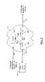
- Embodiments of the present inventionmay be generally employed in a virtual private data network (“VPN”) 2 as shown in FIG. 1 .
- the VPN 2includes local access and transport areas (“LATAs”) 5 and 15 which are connected by an Inter-Exchange Carrier (“IEC”) 10 .
- LATAs 5 and 15may be public data networks operated by a commonly owned Local Exchange Carrier (“LEC”).
- LEC 10may include one or more public data networks which may be operated by a commonly owned IEC.
- the VPN 2may include a frame relay network, asynchronous transfer mode (“ATM”) network, or any other network capable of communicating data conforming to Layers 2 - 4 of the Open Systems Interconnection (“OSI”) model developed by the International Standards Organization, incorporated herein by reference.
- ATMasynchronous transfer mode
- OSIOpen Systems Interconnection
- these networksmay include, but are not limited to, communications protocols conforming to the Multiprotocol Label Switching Standard (“MPLS”) networks and the Transmission Control Protocol/Internet Protocol (“TCP/IP”), which are known to those skilled in the art.
- MPLSMultiprotocol Label Switching Standard
- TCP/IPTransmission Control Protocol/Internet Protocol
- the VPN 2includes a dedicated network circuit which channels data between a VPN host device 112 and a VPN remote device 114 through the LATA 5 , the IEC 10 , and the LATA 15 .
- the dedicated network circuit in the VPN 2only communicates customer data originating and/or terminating at the VPN host device 112 and the VPN remote device 114 . That is, no other customer data is carried over the network circuit. That is, no other customer data is carried over the network circuit.
- the host and remote devices 112 and 114may be local area network (“LAN”) routers or remote access switches (“RAS”) having network interfaces (e.g., frame relay or ATM interfaces) for enabling secured access to the VPN.
- LANlocal area network
- RASremote access switches
- the LATAs 5 and 15 and the IEC 10may include network elements (not shown) which support interworking to enable communications between host and remote devices supporting dissimilar protocols.
- Network elements in a data network supporting interworkingmay translate frame relay data packets or frames to ATM data packets or cells so that a host device may communicate with a remote device having an ATM interface.
- the LATAs 5 and 15 and the IEC 10may further include one or more interconnected network elements, such as switches (not shown), for transmitting data.
- An illustrative LATA data networkwill be discussed in greater detail in the description of FIG. 2 below.
- the dedicated network circuit between the VPN host device 112 and the VPN remote device 114 in the VPN 2includes a dedicated physical circuit and a dedicated logical circuit.
- a dedicated physical circuitis defined as the physical path that connects the end point of a dedicated network circuit to a network device.
- the dedicated physical circuit of the dedicated network circuit between the VPN host device 112 and the VPN remote device 114includes the dedicated physical connection 121 between the VPN host device 112 and the LATA 5 , the dedicated physical connection 106 between the LATA 5 and the IEC 10 , the dedicated physical connection 108 between the IEC 10 and the LATA 15 , and the dedicated physical connection 123 between the LATA 15 and the VPN remote device 114 .
- Routers and switches within the LATAs 5 and 15 and the IEC 10carry the physical signal between the VPN host and remote end devices 112 and 114 through the dedicated physical circuit.
- the VPN host and remote devices 112 and 114may be connected to the dedicated physical circuit described above using user-to-network interfaces (“UNIs”).
- UNIuser-to-network interfaces
- an UNIis the physical demarcation point between a user device (e.g, a host device) and a public data network.
- the dedicated physical connections 106 and 108may include dedicated trunk circuits for carrying the data between the LATAs 5 and 15 and the IEC 10 .
- the dedicated connections 121 and 123may be any of various physical communications media for communicating data such as a 56 Kbps line or a T1 line carried over a four-wire shielded cable or over a fiber optic cable.
- the dedicated physical connections 106 and 108 and the dedicated connections 121 and 123only carry customer data originating and/or terminating at the VPN host device 112 and the VPN remote device 114 . That is, no other customer data is carried over these connections.
- a dedicated logical circuitis defined as a portion of the dedicated network circuit wherein data is sent over variable communication data paths or logical connections established between the first and last network devices within a LATA or IEC network and over dedicated fixed communication data paths or dedicated logical connections between LATAs (or between IECs).
- the dedicated logical circuit of the dedicated network circuit in the VPNmay 2 include a variable communication path within the LATA 5 and a dedicated fixed communication path (i.e., the dedicated logical connection 102 ) between the LATA 5 and the IEC 10 .
- the dedicated logical connections 102 and 104 in the data network 2may include dedicated network-to-network interfaces (“NNIs”) between the last sending switch in a LATA and the first receiving switch in an IEC.
- NNIsnetwork-to-network interfaces
- the dedicated logical connections 106 and 108only carry customer data originating and/or terminating at the VPN host device 112 and the VPN remote device 114 . That is, no other customer data is carried over these connections.
- each dedicated logical circuit in a VPNmay be identified by a unique logical identifier.
- the logical identifieris called a Data Link Connection Identifier (“DLCI”) while in ATM networks the logical identifier is called a Virtual Path Identifier/Virtual Circuit Identifier (“VPI/VCI”).
- DLCIData Link Connection Identifier
- VPN/VCIVirtual Path Identifier/Virtual Circuit Identifier
- the DLCIis a 10-bit address field contained in the header of each data frame and contains identifying information for the dedicated logical circuit as well as information relating to the destination of the data in the frame and service parameters for handling network congestion.
- the designation DLCI 100may be used to identify the dedicated logical circuit between the host device 112 and the remote device 114 . It will be appreciated that in VPNs in which dedicated logical circuit data is communicated through more than one carrier (e.g., an LEC and an IEC) the DLCI designation for the dedicated logical circuit may change in a specific carrier's network. For example, in the VPN 2 , the designation DLCI 100 may identify the dedicated logical circuit in the LATA 5 and LATA 15 but the designation DLCI 800 may identify the dedicated logical circuit in the IEC 10 .
- the designation DLCI 100may identify the dedicated logical circuit in the LATA 5 and LATA 15 but the designation DLCI 800 may identify the dedicated logical circuit in the IEC 10 .
- Illustrative service parameters which may be included in the DLCIinclude a Committed Information Rate (“CIR”) parameter and a Committed Burst Size (“Bc”) parameter.
- CIRCommitted Information Rate
- BcCommitted Burst Size
- the dedicated logical circuitmay be provisioned such that when the CIR or the Bc is exceeded, the receiving switch in the VPN will discard the frame.
- the dedicated logical circuit parametersare not limited to CIR and Bc and that other parameters known to those skilled in the art may also be provisioned, including, but not limited to, Burst Excess Size (“Be”) and Committed Rate Measurement Interval (“Tc”).
- BeBurst Excess Size
- TcCommitted Rate Measurement Interval
- the VPI/VCIis an address field contained in the header of each ATM data cell and contains identifying information for the logical circuit as well as information specifying a data cell's destination and specific bits which may indicate, for example, the existence of congestion in the network and a threshold for discarding cells.
- the dedicated logical circuit in the VPN 2may be a permanent virtual circuit (“PVC”) available to the network at all times or a temporary or a switched virtual circuit (“SVC”) available to the network only as long as data is being transmitted. It should be understood that the VPN 2 may further include additional switches or other interconnected network elements (not shown) creating multiple paths within each LATA and IEC for defining each PVC or SVC in the VPN. It will be appreciated that the data communicated over the dedicated logical connections 102 and 104 may be physically carried by the dedicated physical connections 106 and 108 .
- the VPN 2may also include a failover network 17 for rerouting dedicated logical circuit data, according to an embodiment of the invention.
- the failover network 17may include a network failover circuit including physical connections 134 and 144 and logical connections 122 and 132 for rerouting dedicated logical circuit data in the event of a failure in the network circuit between the VPN host device 112 and the VPN remote device 114 .
- the failover network 17will be described in greater detail in the description of FIG. 4 below.
- the VPN 2may also include a network management system 175 in communication with the LATA 5 , the LATA 15 , and the failover network 17 .
- the network management system 175may be utilized to obtain status information for the dedicated logical and physical circuits between the VPN host device 112 and the VPN remote device 114 .
- the network management system 175may also be utilized for rerouting dedicated logical circuit data in the VPN 2 between the VPN host device 112 and the VPN remote device 114 .
- the network management system 175will be discussed in
- FIG. 2illustrates the LATA 5 in the VPN 2 described in FIG. 1 above, according to an embodiment of the present invention.
- the LATA 5includes interconnected network devices such as switches 186 , 187 , and 188 .
- the VPN 2may also contain other interconnected network devices and elements (not shown) such as digital access and cross connect switches (“DACS”), channel service units (“CSUs”), and data service units (“DSUs”).
- DASdigital access and cross connect switches
- CSUschannel service units
- DSUsdata service units
- the connection data paths of a dedicated logical circuitmay vary between the first and last network devices in a VPN. For example, as shown in FIG.
- the dedicated logical circuit in the LATA 5may include the communication path 185 between the switches 186 and 188 or the communication path 184 between the switches 186 , 187 , and 188 .
- the actual path taken by data through the LATA 5is not fixed and may vary from time to time, such as when automatic rerouting takes place.
- the switches 186 , 187 , and 188may include a signaling mechanism for monitoring and signaling the status of the dedicated logical circuit in the VPN 2 .
- a signaling mechanismfor monitoring and signaling the status of the dedicated logical circuit in the VPN 2 .
- the switchEach time a change in the status of the dedicated logical circuit is detected (e.g., a receiving switch begins dropping frames), the switch generates an alarm or “trap” which may then be communicated to a management station, such as a logical element module (described in detail in the description of FIG. 3 below), in the network management system 175 .
- the signaling mechanismmay be in accord with a Local Management Interface (“LMI”) specification, which provides for the sending and receiving of “status inquiries” between a data network and a host or remote device.
- LMILocal Management Interface
- the LMI specificationincludes obtaining status information through the use of special management frames (in frame relay networks) or cells (in ATM networks).
- frame relay networksfor example, the special management frames monitor the status of logical connections and provide information regarding the health of the network.
- the VPN host and remote devices 112 and 114receive status information from the individual LATAs they are connected to in response to a status request sent in a special management frame or cell.
- the LMI status informationmay include, for example, whether or not the dedicated logical circuit is congested or whether or not the dedicated logical circuit has failed. It should be understood that the parameters and the signaling mechanism discussed above are optional and that other parameters and mechanisms may also be utilized to obtain connection status information for a dedicated logical circuit.
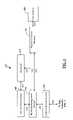
- FIG. 3illustrates the network management system 175 which may be utilized to automatically reroute data from a failed dedicated logical circuit in the VPN of FIG. 1 , according to an embodiment of the invention.
- the network management system 175includes a service order system 160 , a network database 170 , a logical element module 153 , a physical element module 155 , a network management module 176 , and a test module 180 .
- the service order system 160is utilized in the VPN 2 for receiving service orders for provisioning network circuits.
- the service orderincludes information defining the transmission characteristics (i.e., the logical circuit) of the network circuit.
- the service orderalso contains the access speed, CIR, burst rates, and excess burst rates.
- the service order system 160communicates the service order information to a network database 170 over management trunk 172 .
- the network database 170assigns and stores the parameters for the VPN physical circuit portion of the VPN network circuit such as a port number on the switch 186 for transmitting data over the dedicated physical connection 121 to and from the VPN host device 112 .
- the network database 170may also be in communication with an operations support system (not shown) for assigning physical equipment to the dedicated network circuit and for maintaining an inventory of the physical assignments for the dedicated network circuit.
- An illustrative operations support systemis “TIRKS”® (Trunks Integrated Records Keeping System) marketed by TELECORDIATM TECHNOLOGIES, Inc. of Morristown, N.J.
- the network database 170may also be in communication with a Work Force Administration and Control system (“WFA/C”) (not shown) used to assign resources (i.e., technicians) to work on installing the dedicated physical circuit.
- WFA/CWork Force Administration and Control system
- the network management system 175also includes the logical element module 153 which is in communication with the switches in the VPN 2 through management trunks 183 .
- the logical element module 153runs a network management application program to monitor the operation of logical circuits which includes receiving trap data generated by the switches with indicate the status of logical connections.
- the trap datamay be stored in the logical element module 153 for later analysis and review.
- the logical element module 153is also in communication with the network database 170 via management trunks 172 for accessing information regarding logical circuits such as the logical identifier data.
- the logical identifier datamay include, for example, the DLCI or VPI/VCI header information for each data frame or cell in the logical circuit including the circuit's destination and service parameters.
- the logical element module 153may consist of terminals (not shown) that display a map-based graphical user interface (“GUI”) of the logical connections in the data network.
- GUImap-based graphical user interface
- An illustrative logical element moduleis the NAVISCORETM system marketed by LUCENT TECHNOLOGIES, Inc. of Murray Hill, N.J.
- the network management system 175further includes the physical element module 155 in communication with the dedicated physical connections of the dedicated network circuit via management trunks (not shown).
- the physical element module 155runs a network management application program to monitor the operation and retrieve data regarding the operation of the dedicated physical circuit.
- the physical element module 155is also in communication with the network database 170 via management trunks 172 for accessing information regarding physical circuits, such as line speed. Similar to the logical element module 153 , the physical logical element module 155 may also consist of terminals (not shown) that display a map-based GUI of the dedicated physical connections in the LATA 5 .
- An illustrative physical element moduleis the Integrated Testing and Analysis System (“INTAS”), marketed by TELECORDIATM TECHNOLOGIES, Inc. of Morristown, N.J., which provides flow-through testing and analysis of telephony services.
- INTASIntegrated Testing and Analysis System
- the network management system 175further includes the network management module 176 which is in communication with the service order system 160 , the network database 170 , the logical element module 153 , and the physical element module 155 through communications channels 172 . It should be understood that in one embodiment, the network management system 176 may also be in communication with the LATA 15 , the IEC 10 , and the failover network 17 .
- the communications channels 172may be on a LAN.
- the network management module 176may consist of terminals (not shown), which may be part of a general-purpose computer system that displays a map-based GUI of the logical connections in data networks.
- the network management module 175may communicate with the logical element module 153 and the physical element module 155 using a Common Object Request Broker Architecture (“CORBA”).
- CORBACommon Object Request Broker Architecture
- CORBAis an open, vendor-independent architecture and infrastructure which allows different computer applications to work together over one or more networks using a basic set of commands and responses.
- the network management module 176may also serve as an interface for implementing logical operations to provision and maintain network circuits.
- the logical operationsmay be implemented as machine instructions stored locally or as instructions retrieved from the logical and physical element modules 153 and 155 .
- An illustrative method detailing the provisioning and maintenance of network circuits in a data networkis presented in U.S. patent application Ser. No. 10/348,592, entitled “Method And System For Provisioning And Maintaining A Circuit In A Data Network,” filed on Jan.
- An illustrative network management moduleis the Broadband Network Management System® (“BBNMS”) marketed by TELECORDIATM TECHNOLOGIES, Inc. of Morristown, N.J.
- BBNMSBroadband Network Management System
- FIG. 4illustrates a failover data network for rerouting dedicated logical circuit data, according to one embodiment of the present invention.
- the failover network 17includes an IEC 20 , a LATA 25 , and an IEC 30 .
- the failover networkfurther includes a network failover circuit which includes a physical failover circuit and a logical failover circuit.
- the physical failover circuitincludes the physical connection 134 between the LATA 5 (shown in FIG. 1 ) and the IEC 20 , the physical connection 136 between the IEC 20 and the LATA 25 , the physical connection 138 between the LATA 25 and the IEC 30 , and the physical connection 144 between the IEC 30 and the LATA 15 (shown in FIG. 1 ).
- the logical failover circuitmay include the logical connection 122 between the LATA 5 (shown in FIG. 1 ) and the IEC 20 , the logical connection 124 between the IEC 20 and the LATA 25 , the logical connection 126 between the LATA 25 and the IEC 30 , and the logical connection 132 between the IEC 30 and the LATA 15 (shown in FIG. 1 ).
- the network failover circuit illustrated in the failover network 17may include a dedicated physical circuit and a dedicated logical circuit provisioned by a network service provider serving the LATAs 5 , 15 , and 25 and the IECs 20 and 30 , for rerouting logical data from a failed logical circuit.
- FIG. 5illustrates a flowchart describing logical operations 500 for automatically rerouting dedicated logical circuit data in a VPN, according to an embodiment of the invention.
- the logical operations 500begin at operation 505 where the network management module 176 receives status information for a logical circuit in the data network 2 .
- the status informationmay be received by communicating with the logical element module 153 to request trap data generated by one or more switches in the data network which indicate the status of one or more logical connections making up the logical circuit.
- the network management module 176may be configured to automatically monitor the dedicated logical circuits in the VPN 2 for trap data to identify a dedicated logical circuit failure.
- the logical operations 500continue at operation 510 where the network management module 176 determines whether a dedicated logical circuit failure has occurred based on the received status information.
- a dedicated logical circuit failureoccurs when one or more dedicated logical connections in a dedicated logical circuit have failed.
- trap data indicating a logical connection failuremay include status information indicating that a switch in the data network is discarding frames or cells. Such an event may occur, for example, when the maximum CIR or Bc (as specified in the DLCI of a frame in a frame relay network, for example) is exceeded. For example, in the VPN 2 shown in FIG.
- the “X” marking the dedicated logical connections 102 and 104indicate that both connections are “down beyond” (i.e., not communicating data) the portion of the dedicated logical circuit in the LATA data networks 5 and 15 .
- such a conditionmay indicate that the dedicated logical circuit failure lies in the IEC data network 10 .
- the logical operations 500then return to operation 505 where the network management module 176 again receives status information for the dedicated logical circuit. If, however, at operation 510 it is determined that a dedicated logical circuit failure has occurred, the logical operations continue to operation 515 .
- the network management module 176identifies a logical failover circuit for rerouting the data from the dedicated logical circuit in the VPN. For example, if as shown in FIG.
- a logical failover circuit in the failover network 17may be selected to reroute the data such that it bypasses the IEC data network 10 .
- the logical failover circuitmay be selected including the logical connections 122 , 124 , 126 , and 132 (as shown in FIG. 4 ) to reroute the data from the VPN host device 112 , through the LATA 5 , the IEC 20 , the LATA 25 , the IEC 30 , the LATA 15 , and finally to the VPN remote device 114 .
- the logical failover circuit selectedmay be a dedicated circuit which is only utilized for rerouting logical data from failed a failed logical circuit (i.e., the failover circuit does not normally communicate data traffic).
- the logical failover circuitmay be another dedicated logical circuit which is normally utilized for communicating data traffic in the VPN.
- the selection of the logical failover circuitmay also include determining whether one or more dedicated logical connections in the circuit are currently communicating data traffic or are currently unused. If currently unused, the dedicated logical connections may be selected for rerouting logical data.
- the logical failover circuitmay be a currently unused non-dedicated logical circuit (i.e., not restricted to carrying VPN customer traffic) in a public data network.
- the selection of the logical failover circuitmay be manually initiated.
- a technician at the logical element module 153 or the network management module 176may utilize a map-based GUI displaying the dedicated logical connections in the LATA data networks 5 and 15 and their status.
- a dedicated logical failover circuit(or a currently unused logical circuit with available logical connections) may then be selected as a logical failover circuit for communicating data from a failed dedicated logical circuit.
- the logical operations 500then continue from operation 515 to operation 520 .
- the dedicated logical circuits in a VPNare identified by a logical circuit identifier (ID).
- IDa logical circuit identifier
- the network management module 176compares the identifier (e.g. the DLCI or VPI/VCI) of the dedicated logical circuit to the identifier of the selected logical failover circuit. If at operation 520 , it is determined that the identifiers of the failed dedicated logical circuit and the logical failover circuit are the same, the logical operations 500 then continue from operation 520 to operation 530 .
- the logical operations 500then continue from operation 520 to operation 525 where the network management module 176 renames the logical circuit ID of the failed dedicated logical circuit to the ID of the logical failover circuit in the database 170 .
- the logical operations 500then continue from operation 525 to operation 530 .
- a dedicated failover logical circuitmay be assigned to an existing dedicated logical circuit in a VPN and identified with the same ID as the existing dedicated logical circuit.
- a logical failover circuit which is already an existing logical circuiti.e., normally communicates data traffic in a data network
- the logical identifier of a failed dedicated logical circuitmay be renamed so that it is in accord with a current logical identifier of a logical failover circuit.
- a dedicated logical circuitmay be identified as DLCI 100 while a logical failover circuit may be identified as DLCI 250 .
- the dedicated logical circuitmay be renamed from DLCI 100 to DLCI 250 . It will further be appreciated that the network management module 175 may store the changes to logical circuit identifiers as reroute data in the database 170 . This reroute data may then be accessed to rename the logical identifier of the failed dedicated logical circuit once the trouble in the failed dedicated logical circuit has been repaired.
- the network management module 176reroutes the data from the failed dedicated logical circuit to the logical failover circuit. It will be appreciated that the reroute of the data may be accomplished from the logical management module 153 or the network management module 176 which, in communication with the switches in the VPN 2 (and the failover network 17 ), sends instructions to reroute the data from the dedicated NNIs or logical connections 102 and 104 to the failover NNIs or logical connections 122 , 124 , 126 , and 132 in the logical failover circuit. The logical operations 500 then continue from operation 530 to operation 535 .
- the network management module 176determines whether the failed dedicated logical circuit has been restored. This determination may be made, for example, by continuous or periodic logical circuit monitoring of the link status of the failed dedicated logical circuit, which may be performed by the logical element module 153 in communication with the network management module 176 , to establish that the logical connections 102 (at the LATA 5 ) and 104 (at the LATA 15 ) are successfully communicating data. If at operation 535 it is determined that the failed dedicated logical circuit has not been restored, the logical operations 500 return to operation 530 where the rerouting of the data is maintained on the logical failover circuit.
- the logical operations 535continue to operation 540 where the data on the logical failover circuit is rerouted back to the restored dedicated logical circuit. Similar to the rerouting of the data onto the logical failover circuit, the rerouting of the data back onto the restored dedicated logical circuit may be accomplished from the network management module 176 which, in communication with the switches in the VPN 2 (and the failover network 17 ) sends instructions to reroute the data from the failover NNIs or logical connections 122 , 124 , 126 , and 132 to the restored dedicated NNIs or logical connections 102 and 104 in the VPN 2 . The logical operations 500 then end.
- the logical circuit failover proceduremay be initiated as part of a customer subscription service offered by the VPN service provider.
- the subscription servicemay include use of the logical failover circuit for a predetermined time period after the VPN customer's data has been rerouted. For example, a VPN customer subscribing to the failover service would automatically have the logical circuit failover procedure initiated and the customer's data would be rerouted for up to two hours over the logical failover circuit after a determination that the customer's VPN network circuit has failed. If a VPN customer is not a subscriber, the failover service may still be initiated and the customer may be billed based on the length of time the failover service was in service.
- the VPN customermay be offered the failover service by the service provider in real-time (i.e., upon determining a VPN network circuit failure).
- the embodiments of the invention described aboveprovide for a method and system for automatically rerouting data from failed logical circuits in a VPN.
- a dedicated logical circuit in the VPNis monitored for status information indicating a failure.
- the data in the circuitmay be rerouted to a “logical failover network,” thereby minimizing lost data until the trouble in the logical circuit is resolved.
Landscapes
- Engineering & Computer Science (AREA)
- Computer Networks & Wireless Communication (AREA)
- Signal Processing (AREA)
- Theoretical Computer Science (AREA)
- Physics & Mathematics (AREA)
- General Engineering & Computer Science (AREA)
- General Physics & Mathematics (AREA)
- Quality & Reliability (AREA)
- Computing Systems (AREA)
- Computer Security & Cryptography (AREA)
- Environmental & Geological Engineering (AREA)
- Computer Hardware Design (AREA)
- Mathematical Physics (AREA)
- Data Exchanges In Wide-Area Networks (AREA)
Abstract
Description
Claims (26)
Priority Applications (6)
| Application Number | Priority Date | Filing Date | Title |
|---|---|---|---|
| US10/745,168US7639606B2 (en) | 2003-12-23 | 2003-12-23 | Method and system for automatically rerouting logical circuit data in a virtual private network |
| US12/609,415US8345543B2 (en) | 2003-12-23 | 2009-10-30 | Methods and systems for automatically rerouting logical circuit data |
| US13/690,777US8547831B2 (en) | 2003-12-23 | 2012-11-30 | Methods and systems for automatically rerouting logical circuit data |
| US14/038,187US8730795B2 (en) | 2003-12-23 | 2013-09-26 | Methods and systems for automatically rerouting logical circuit data |
| US14/281,476US9059900B2 (en) | 2003-12-23 | 2014-05-19 | Methods and systems for automatically rerouting logical circuit data |
| US14/737,201US9672121B2 (en) | 2003-12-23 | 2015-06-11 | Methods and systems for automatically rerouting logical circuit data |
Applications Claiming Priority (1)
| Application Number | Priority Date | Filing Date | Title |
|---|---|---|---|
| US10/745,168US7639606B2 (en) | 2003-12-23 | 2003-12-23 | Method and system for automatically rerouting logical circuit data in a virtual private network |
Related Child Applications (1)
| Application Number | Title | Priority Date | Filing Date |
|---|---|---|---|
| US12/609,415ContinuationUS8345543B2 (en) | 2003-12-23 | 2009-10-30 | Methods and systems for automatically rerouting logical circuit data |
Publications (2)
| Publication Number | Publication Date |
|---|---|
| US20050172160A1 US20050172160A1 (en) | 2005-08-04 |
| US7639606B2true US7639606B2 (en) | 2009-12-29 |
Family
ID=34807412
Family Applications (6)
| Application Number | Title | Priority Date | Filing Date |
|---|---|---|---|
| US10/745,168Expired - LifetimeUS7639606B2 (en) | 2003-12-23 | 2003-12-23 | Method and system for automatically rerouting logical circuit data in a virtual private network |
| US12/609,415Expired - Fee RelatedUS8345543B2 (en) | 2003-12-23 | 2009-10-30 | Methods and systems for automatically rerouting logical circuit data |
| US13/690,777Expired - LifetimeUS8547831B2 (en) | 2003-12-23 | 2012-11-30 | Methods and systems for automatically rerouting logical circuit data |
| US14/038,187Expired - LifetimeUS8730795B2 (en) | 2003-12-23 | 2013-09-26 | Methods and systems for automatically rerouting logical circuit data |
| US14/281,476Expired - LifetimeUS9059900B2 (en) | 2003-12-23 | 2014-05-19 | Methods and systems for automatically rerouting logical circuit data |
| US14/737,201Expired - Fee RelatedUS9672121B2 (en) | 2003-12-23 | 2015-06-11 | Methods and systems for automatically rerouting logical circuit data |
Family Applications After (5)
| Application Number | Title | Priority Date | Filing Date |
|---|---|---|---|
| US12/609,415Expired - Fee RelatedUS8345543B2 (en) | 2003-12-23 | 2009-10-30 | Methods and systems for automatically rerouting logical circuit data |
| US13/690,777Expired - LifetimeUS8547831B2 (en) | 2003-12-23 | 2012-11-30 | Methods and systems for automatically rerouting logical circuit data |
| US14/038,187Expired - LifetimeUS8730795B2 (en) | 2003-12-23 | 2013-09-26 | Methods and systems for automatically rerouting logical circuit data |
| US14/281,476Expired - LifetimeUS9059900B2 (en) | 2003-12-23 | 2014-05-19 | Methods and systems for automatically rerouting logical circuit data |
| US14/737,201Expired - Fee RelatedUS9672121B2 (en) | 2003-12-23 | 2015-06-11 | Methods and systems for automatically rerouting logical circuit data |
Country Status (1)
| Country | Link |
|---|---|
| US (6) | US7639606B2 (en) |
Cited By (16)
| Publication number | Priority date | Publication date | Assignee | Title |
|---|---|---|---|---|
| US20060083251A1 (en)* | 2004-10-20 | 2006-04-20 | Kenji Kataoka | Route control method of label switch path |
| US7768904B2 (en) | 2004-04-22 | 2010-08-03 | At&T Intellectual Property I, L.P. | Method and system for fail-safe renaming of logical circuit identifiers for rerouted logical circuits in a data network |
| US7890618B2 (en) | 2003-01-21 | 2011-02-15 | At&T Intellectual Property I, L.P. | Method and system for provisioning and maintaining a circuit in a data network |
| US8031620B2 (en) | 2003-12-23 | 2011-10-04 | At&T Intellectual Property I, L.P. | Method and system for real time simultaneous monitoring of logical circuits in a data network |
| US8031588B2 (en) | 2003-12-23 | 2011-10-04 | At&T Intellectual Property I, L.P. | Methods and systems for automatically renaming logical Circuit identifiers for rerouted logical circuits in a data network |
| US8199638B2 (en) | 2003-12-23 | 2012-06-12 | At&T Intellectual Property I, L.P. | Method and system for automatically rerouting logical circuit data in a data network |
| US8203933B2 (en) | 2003-12-23 | 2012-06-19 | At&T Intellectual Property I, L.P. | Method and system for automatically identifying a logical circuit failure in a data network |
| US8223632B2 (en) | 2003-12-23 | 2012-07-17 | At&T Intellectual Property I, L.P. | Method and system for prioritized rerouting of logical circuit data in a data network |
| US8243592B2 (en) | 2003-12-23 | 2012-08-14 | At&T Intellectual Property I, L.P. | Methods and systems for automatically rerouting data in a data network |
| US8295162B2 (en) | 2006-05-16 | 2012-10-23 | At&T Intellectual Property I, L.P. | System and method to achieve sub-second routing performance |
| US8339988B2 (en) | 2004-04-22 | 2012-12-25 | At&T Intellectual Property I, L.P. | Method and system for provisioning logical circuits for intermittent use in a data network |
| US8339938B2 (en) | 2004-04-22 | 2012-12-25 | At&T Intellectual Property I, L.P. | Method and system for automatically tracking the rerouting of logical circuit data in a data network |
| US8345543B2 (en) | 2003-12-23 | 2013-01-01 | At&T Intellectual Property I, L.P. | Methods and systems for automatically rerouting logical circuit data |
| US8345537B2 (en) | 2004-04-22 | 2013-01-01 | At&T Intellectual Property I, L.P. | Methods and systems for automatically rerouting logical circuit data from a logical circuit failure to a dedicated backup circuit in a data network |
| US9973907B1 (en)* | 2012-07-02 | 2018-05-15 | CSC Holdings, LLC | Method and system for service continuity, network preference, and reporting logic with SMS services |
| US20220239369A1 (en)* | 2019-06-21 | 2022-07-28 | Nippon Telegraph And Telephone Corporation | Transmission device, restoration method, program, and transmission system |
Families Citing this family (14)
| Publication number | Priority date | Publication date | Assignee | Title |
|---|---|---|---|---|
| US7630302B2 (en)* | 2003-12-23 | 2009-12-08 | At&T Intellectual Property I, L.P. | Method and system for providing a failover circuit for rerouting logical circuit data in a data network |
| US7350099B2 (en)* | 2003-12-23 | 2008-03-25 | At&T Bls Intellectual Property, Inc. | Method and system for utilizing a logical failover circuit for rerouting data between data networks |
| US7275192B2 (en)* | 2004-04-22 | 2007-09-25 | At&T Bls Intellectual Property, Inc. | Method and system for on demand selective rerouting of logical circuit data in a data network |
| US7782877B2 (en)* | 2004-11-03 | 2010-08-24 | Verizon Business Global Llc | Network-based dedicated backup service |
| US7480822B1 (en)* | 2005-07-13 | 2009-01-20 | Symantec Corporation | Recovery and operation of captured running states from multiple computing systems on a single computing system |
| US20080052390A1 (en)* | 2006-08-28 | 2008-02-28 | International Business Machines Corporation | System and method for virtual private network address persistence |
| JP2008113955A (en)* | 2006-11-07 | 2008-05-22 | Aruze Corp | Game device |
| US8305904B1 (en)* | 2008-05-01 | 2012-11-06 | Sprint Communications Company L.P. | Method and system for verifying repairs in a telecommunication network |
| JP5292929B2 (en)* | 2008-06-09 | 2013-09-18 | 富士通株式会社 | Monitoring device |
| KR101538244B1 (en)* | 2010-12-10 | 2015-07-20 | 닛본 덴끼 가부시끼가이샤 | Server management apparatus, server management method, and program |
| US8874956B2 (en)* | 2012-09-18 | 2014-10-28 | Datadirect Networks, Inc. | Data re-protection in a distributed replicated data storage system |
| US9038151B1 (en)* | 2012-09-20 | 2015-05-19 | Wiretap Ventures, LLC | Authentication for software defined networks |
| US9253052B2 (en)* | 2013-08-28 | 2016-02-02 | Institute For Information Industry | Integration network device and service integration method thereof |
| CN104917623B (en)* | 2014-03-10 | 2019-09-13 | 南京中兴新软件有限责任公司 | A method and device for implementing SDN network communication management |
Citations (122)
| Publication number | Priority date | Publication date | Assignee | Title |
|---|---|---|---|---|
| US4905233A (en)* | 1987-11-23 | 1990-02-27 | Harris Corporation | Multiple path routing mechanism for packet communications network |
| US5016244A (en) | 1989-09-08 | 1991-05-14 | Honeywell Inc. | Method for controlling failover between redundant network interface modules |
| US5065392A (en) | 1990-04-10 | 1991-11-12 | Dsc Communications Corporation | Network controller scheduling system and method of operation |
| US5265092A (en) | 1992-03-18 | 1993-11-23 | Digital Equipment Corporation | Synchronization mechanism for link state packet routing |
| US5375126A (en) | 1991-04-09 | 1994-12-20 | Hekimian Laboratories, Inc. | Integrated logical and physical fault diagnosis in data transmission systems |
| US5408461A (en) | 1993-03-19 | 1995-04-18 | Fujitsu Limited | Path route test apparatus for use in an ATM transmission system |
| US5539817A (en) | 1995-12-11 | 1996-07-23 | Stentor Resource Centre, Inc. | Wide area centrex toll service with novel translation |
| US5544170A (en)* | 1990-03-16 | 1996-08-06 | Fujitsu Limited | ATM transmission system with a variable transmission rate |
| US5548639A (en)* | 1991-10-22 | 1996-08-20 | Fujitsu Limited | Distributed control of telecommunication network for setting up an alternative communication path |
| US5559959A (en) | 1993-09-16 | 1996-09-24 | Siemens Aktiengesellschaft | Method for transmitting message cells via redundant virtual path pairs of an atm communication network |
| US5629938A (en) | 1995-05-25 | 1997-05-13 | At&T | Method for automated provisioning of dedicated circuits |
| US5633859A (en)* | 1994-09-16 | 1997-05-27 | The Ohio State University | Method and apparatus for congestion management in computer networks using explicit rate indication |
| US5650994A (en) | 1995-05-16 | 1997-07-22 | Bell Atlantic Network Services, Inc. | Operation support system for service creation and network provisioning for video dial tone networks |
| US5832197A (en) | 1995-12-06 | 1998-11-03 | Nec Corporation | Alternate routing by increasing initially low QOS value of a selected alternate path during failure to user-specified value |
| US5856981A (en)* | 1997-05-15 | 1999-01-05 | Lucent Technologies Inc. | Reliable connection oriented networks |
| US5894475A (en) | 1996-06-28 | 1999-04-13 | At&T Corp. | Switched voice and data ATM network with billing system |
| US5926456A (en)* | 1993-08-31 | 1999-07-20 | Hitachi, Ltd. | Path changing system and method for use in ATM communication apparatus |
| US5936939A (en)* | 1995-05-22 | 1999-08-10 | Fore Systems, Inc. | Digital network including early packet discard mechanism with adjustable threshold |
| US6028863A (en) | 1996-06-10 | 2000-02-22 | Fujitsu Limited | Method and apparatus for negotiating connection identifier |
| US6038219A (en)* | 1996-12-31 | 2000-03-14 | Paradyne Corporation | User-configurable frame relay network |
| US6091951A (en) | 1997-05-14 | 2000-07-18 | Telxon Corporation | Seamless roaming among multiple networks |
| US6104998A (en) | 1998-03-12 | 2000-08-15 | International Business Machines Corporation | System for coding voice signals to optimize bandwidth occupation in high speed packet switching networks |
| US6108300A (en) | 1997-05-02 | 2000-08-22 | Cisco Technology, Inc | Method and apparatus for transparently providing a failover network device |
| US6108307A (en) | 1997-12-12 | 2000-08-22 | Newbridge Networks Corporation | Frame relay priority queses to offer multiple service classes |
| US6118763A (en) | 1996-09-27 | 2000-09-12 | Inventions, Inc. | Transmission of voice over an asynchronous network |
| US6147998A (en) | 1997-08-26 | 2000-11-14 | Visual Networks Technologies, Inc. | Method and apparatus for performing in-service quality of service testing |
| US6167025A (en)* | 1996-09-11 | 2000-12-26 | Telcordia Technologies, Inc. | Methods and apparatus for restoring connections in an ATM network |
| US6181679B1 (en)* | 1993-03-19 | 2001-01-30 | International Business Machines Corporation | Management of packet transmission networks |
| US6181675B1 (en)* | 1997-07-08 | 2001-01-30 | Nec Corporation | Uninterrupted switching between active and backup systems in ATM communication apparatus |
| US6185695B1 (en) | 1998-04-09 | 2001-02-06 | Sun Microsystems, Inc. | Method and apparatus for transparent server failover for highly available objects |
| US6195416B1 (en) | 1998-03-23 | 2001-02-27 | At&T Corp. | Method to trap a called number in a telecommunications network |
| US20010000700A1 (en) | 1998-06-30 | 2001-05-03 | Hossein Eslambolchi | Method and apparatus for achieving fast reconnection of permanent virtual channels in a frame relay network |
| US6259696B1 (en)* | 1996-12-05 | 2001-07-10 | Hitachi, Ltd. | ATM switch and congestion control method |
| US6269401B1 (en) | 1998-08-28 | 2001-07-31 | 3Com Corporation | Integrated computer system and network performance monitoring |
| US6311288B1 (en) | 1998-03-13 | 2001-10-30 | Paradyne Corporation | System and method for virtual circuit backup in a communication network |
| US20020001307A1 (en) | 2000-05-20 | 2002-01-03 | Equipe Communications Corporation | VPI/VCI availability index |
| US6360260B1 (en) | 1996-11-12 | 2002-03-19 | International Business Machines Corporation | Discovery features for SNMP managed devices |
| US6377548B1 (en) | 1997-10-14 | 2002-04-23 | Lucent Technologies Inc. | Method for admitting new connections based on measured quantities in a multiple access system for communications networks |
| US20020072358A1 (en) | 2000-12-13 | 2002-06-13 | Telefonaktiebolaget Lm Ericsson | Methods and apparatus for real-time performance monitoring in a wireless communication network |
| US20020089985A1 (en) | 2000-10-27 | 2002-07-11 | Alcatel | Access control unit |
| US6421722B1 (en) | 1999-04-30 | 2002-07-16 | Alcatel Canada Inc. | Method and apparatus for providing internetworking service reliability |
| US6424629B1 (en) | 1998-11-23 | 2002-07-23 | Nortel Networks Limited | Expediting reconvergence in a routing device |
| US6449259B1 (en) | 1997-03-31 | 2002-09-10 | Lucent Technologies Inc. | Communication controller |
| US6456306B1 (en) | 1995-06-08 | 2002-09-24 | Nortel Networks Limited | Method and apparatus for displaying health status of network devices |
| US6473398B1 (en) | 1996-03-15 | 2002-10-29 | Alcatel Canada Inc. | Congestion management in managed packet-switched networks |
| US20020172148A1 (en) | 1999-09-14 | 2002-11-21 | Kim Dongsoo S. | Method and apparatus for protection switching in virtual private networks |
| US20030043753A1 (en) | 1994-12-23 | 2003-03-06 | Chartered Semiconductor Manufacturing Ltd. | Method and apparatus for analyzing events in a telecommunications system |
| US20030051049A1 (en) | 2001-08-15 | 2003-03-13 | Ariel Noy | Network provisioning in a distributed network management architecture |
| US20030051195A1 (en) | 2000-05-05 | 2003-03-13 | Bosa Patrick A. | Systems and methods for isolating faults in computer networks |
| US6535990B1 (en) | 2000-01-10 | 2003-03-18 | Sun Microsystems, Inc. | Method and apparatus for providing fault-tolerant addresses for nodes in a clustered system |
| US6538987B1 (en) | 1999-03-25 | 2003-03-25 | Ciena Corporation | Rapid ring protection switching system |
| US6553015B1 (en)* | 1998-05-20 | 2003-04-22 | Nec Corporation | High speed switching of communications links without interrupting ATM cell traffic |
| US6556659B1 (en) | 1999-06-02 | 2003-04-29 | Accenture Llp | Service level management in a hybrid network architecture |
| US20030086413A1 (en) | 2001-08-31 | 2003-05-08 | Nec Corporation | Method of transmitting data |
| US20030091024A1 (en) | 2001-09-27 | 2003-05-15 | Siemens Information And Communications Networks, Inc. | Transparent interchangeable network (TIN) |
| US6570846B1 (en)* | 1998-05-25 | 2003-05-27 | Samsung Electronics Co., Ltd. | Method for monitoring and controlling traffic in real time in an ATM switching node |
| US6581166B1 (en) | 1999-03-02 | 2003-06-17 | The Foxboro Company | Network fault detection and recovery |
| US6590899B1 (en) | 1996-12-31 | 2003-07-08 | Alcatel Usa Sourcing, L.P. | System for consolidating telecommunications traffic onto a minimum number of output paths |
| US20030128692A1 (en) | 2002-01-04 | 2003-07-10 | Mitsumori Derek Hisami | Voice over internet protocol (VoIP) network performance monitor |
| US6594246B1 (en) | 1998-07-10 | 2003-07-15 | Malibu Networks, Inc. | IP-flow identification in a wireless point to multi-point transmission system |
| US6594268B1 (en)* | 1999-03-11 | 2003-07-15 | Lucent Technologies Inc. | Adaptive routing system and method for QOS packet networks |
| US6597689B1 (en) | 1998-12-30 | 2003-07-22 | Nortel Networks Limited | SVC signaling system and method |
| US20030152028A1 (en) | 2000-06-30 | 2003-08-14 | Vilho Raisanen | Method and system for managing quality of service by feeding information into the packet network |
| US6608831B1 (en) | 1999-07-16 | 2003-08-19 | Cisco Technology, Inc. | Breakout/break-in hybrid network system |
| US20030185151A1 (en) | 2002-03-27 | 2003-10-02 | Fujitsu Limited | Information processing system and information terminal thereof having a route switching function |
| US6643254B1 (en)* | 1998-08-06 | 2003-11-04 | Fujitsu Limited | Rerouting method for a PVC route on an ATM network and a network management system using the rerouting method |
| US6697329B1 (en) | 1998-05-28 | 2004-02-24 | Alcatel Canada Inc. | Operator directed routing of connections in a digital communications network |
| US6716165B1 (en) | 2001-03-02 | 2004-04-06 | Ge Medical Systems Information Technologies, Inc. | Patient telemetry device and leadset designs for providing antenna diversity |
| US20040090973A1 (en) | 1994-05-05 | 2004-05-13 | Sprint Communications Company, L. P. | ATM gateway system |
| US6738459B1 (en) | 2000-03-07 | 2004-05-18 | Verizon Corporate Services Group Inc. | Method and apparatus for efficiently utilizing a communications infrastructure |
| US20040125776A1 (en) | 2002-12-26 | 2004-07-01 | Haugli Hans C. | Peer-to-peer wireless data communication system with progressive dynamic routing |
| US6763476B1 (en) | 2001-04-03 | 2004-07-13 | Unisys Corporation | Enhanced timer queue mechanism for dynamic capacity increase |
| US6766113B1 (en) | 2000-06-16 | 2004-07-20 | Lucent Technologies Inc. | Control channel processor and switching mechanism |
| US20040141464A1 (en) | 2003-01-21 | 2004-07-22 | Bellsouth Intellectual Property Corporation | Method and system for obtaining logical performance data for a circuit in a data network |
| US6781952B2 (en) | 2000-11-27 | 2004-08-24 | Nec Corporation | Establishment of designated S-PVC connection in PNNI operation ATM switching apparatus network |
| US20040172574A1 (en) | 2001-05-25 | 2004-09-02 | Keith Wing | Fault-tolerant networks |
| US6795393B1 (en) | 1999-12-24 | 2004-09-21 | Alcatel Usa Sourcing, L.P. | Method and apparatus for errorless path protection and rearrangement |
| US6795394B1 (en) | 2000-04-26 | 2004-09-21 | Nortel Networks Limited | Data network having enhanced availability of extra traffic |
| US6810043B1 (en) | 1998-05-11 | 2004-10-26 | Fujitsu Limited | Scheduling circuitry and methods |
| US6823477B1 (en) | 2001-01-23 | 2004-11-23 | Adaptec, Inc. | Method and apparatus for a segregated interface for parameter configuration in a multi-path failover system |
| US6826184B1 (en) | 1999-12-29 | 2004-11-30 | Nortel Networks Limited | Method and system for multi-service cut-through switching through a connection-oriented network |
| US6829223B1 (en) | 1998-12-31 | 2004-12-07 | Vigilant Networks Llc | Computer network physical-layer analysis method and system |
| US20050002339A1 (en) | 2003-06-20 | 2005-01-06 | Marconi Communications, Inc. | Distributed protection switching |
| US20050013242A1 (en)* | 2003-07-18 | 2005-01-20 | Feihong Chen | Methods and devices for re-routing traffic |
| US6862351B2 (en) | 2002-05-06 | 2005-03-01 | Bellsouth Intellectual Property Corporation | Monitoring system for a communication network |
| US6865170B1 (en) | 1997-06-19 | 2005-03-08 | Idt Corporation | Metropolitan wide area network |
| US6882652B1 (en) | 1999-08-06 | 2005-04-19 | Tellabs Operations, Inc. | Private lines traversing a packet network and re-arrangement of channels among packet network connections |
| US20050138203A1 (en) | 2003-12-23 | 2005-06-23 | Bellsouth Intellectual Property Corporation | Method and system for utilizing a logical failover circuit for rerouting data between data networks |
| US20050135237A1 (en) | 2003-12-23 | 2005-06-23 | Bellsouth Intellectual Property Corporation | Method and system for automatically rerouting logical circuit data in a data network |
| US20050135254A1 (en) | 2003-12-23 | 2005-06-23 | Bellsouth Intellectual Property Corporation | Method and system for automatically rerouting data from an overbalanced logical circuit in a data network |
| US20050138476A1 (en) | 2003-12-23 | 2005-06-23 | Bellsouth Intellectual Property Corporation | Method and system for prioritized rerouting of logical circuit data in a data network |
| US20050135238A1 (en) | 2003-12-23 | 2005-06-23 | Bellsouth Intellectual Property Corporation | Method and system for providing a failover circuit for rerouting logical circuit data in a data network |
| US20050135263A1 (en) | 2003-12-23 | 2005-06-23 | Bellsouth Intellectual Property Corporation | Method and system for real time simultaneous monitoring of logical circuits in a data network |
| US20050152028A1 (en) | 2003-12-16 | 2005-07-14 | Carl Zeiss Jena Gmbh | Illumination device for a microscope |
| US6925578B2 (en) | 2001-09-29 | 2005-08-02 | Hewlett-Packard Development Company, L.P. | Fault-tolerant switch architecture |
| US20050172160A1 (en) | 2003-12-23 | 2005-08-04 | Bellsouth Intellectual Property Corporation | Method and system for automatically rerouting logical circuit data in a virtual private network |
| US20050172174A1 (en) | 2003-12-23 | 2005-08-04 | Bellsouth Intellectual Property Corporation | Method and system for automatically identifying a logical circuit failure in a data network |
| US6952395B1 (en) | 2001-06-01 | 2005-10-04 | Calix Networks, Inc. | Optical network restoration |
| US20050238024A1 (en) | 2004-04-22 | 2005-10-27 | Bellsouth Intellectual Property Corporation | Method and system for provisioning logical circuits for intermittent use in a data network |
| US20050238007A1 (en) | 2004-04-22 | 2005-10-27 | Bellsouth Intellectual Property Corporation | Method and system for automatically tracking the rerouting of logical circuit data in a data network |
| US20050237925A1 (en) | 2004-04-22 | 2005-10-27 | Bellsouth Intellectual Property Corporation | Method and system for automatically rerouting logical circuit data from a logical circuit failure to dedicated backup circuit in a data network |
| US20050240840A1 (en) | 2004-04-22 | 2005-10-27 | Bellsouth Intellectual Property Corporation | Method and system for on demand selective rerouting of logical circuit data in a data network |
| US20050238006A1 (en) | 2004-04-22 | 2005-10-27 | Bellsouth Intellectual Property Corporation | Method and system for fail-safe renaming of logical circuit identifiers for rerouted logical circuits in a data network |
| US6973034B1 (en) | 1999-06-29 | 2005-12-06 | Cisco Technology, Inc. | Technique for collecting operating information from network elements, and for controlling network element behavior in a feedback-based, adaptive data network |
| US6973037B1 (en) | 2000-05-04 | 2005-12-06 | Nortel Networks Limited | System and method for dynamically varying integrated services digital network (isdn) interface bandwidth |
| US6981039B2 (en) | 2000-08-01 | 2005-12-27 | Qwest Communications International, Inc. | Fault management in a VDSL network |
| US6983401B2 (en) | 2002-05-01 | 2006-01-03 | Bellsouth Intellectual Property Corporation | System and method for generating a chronic circuit report for use in proactive maintenance of a communication network |
| US6990616B1 (en) | 2000-04-24 | 2006-01-24 | Attune Networks Ltd. | Analysis of network performance |
| US7027053B2 (en) | 2002-02-28 | 2006-04-11 | Sun Microsystems, Inc. | Graphical user interface for indicating device failover |
| US7072331B2 (en) | 2001-08-23 | 2006-07-04 | Real Communications, Inc. | Configurable digital subscriber loop access and end-to-end data and analog voice connection system |
| US20060146700A1 (en) | 2003-12-23 | 2006-07-06 | Bellsouth Intellectual Property Corporation | Method and system for automatically renaming logical circuit identifiers for rerouted logical circuits in a data network |
| US7093155B2 (en) | 2003-11-18 | 2006-08-15 | Hitachi, Ltd. | Information processing system and method for path failover |
| US7120819B1 (en) | 2001-11-15 | 2006-10-10 | 3Com Corporation | Method and system for fault diagnosis in a data network |
| US7120148B1 (en) | 2002-02-12 | 2006-10-10 | Cisco Technology, Inc. | System and method for providing source awareness in a wireless application protocol network environment |
| US7146000B2 (en) | 2002-01-25 | 2006-12-05 | Level (3) Communications | Routing engine for telecommunications network |
| US7165192B1 (en) | 2003-12-19 | 2007-01-16 | Sun Microsystems, Inc. | Fault isolation in large networks |
| US20070050492A1 (en) | 1998-07-10 | 2007-03-01 | Van Drebbel Mariner Llc | Method of operation for the integration of differentiated services (Diff-Serv) marked IP-flows into a quality of service (QoS) priorities in a wireless point to multi-point (PtMP) transmission system |
| US7200148B1 (en) | 2002-06-28 | 2007-04-03 | Bellsouth Intellectual Property Corp. | System and method for analyzing asynchronous transfer mode communications |
| US7209452B2 (en) | 2002-12-13 | 2007-04-24 | Bellsouth Intellectual Property Corporation | Method and system for retrieving link management interface status for a logical port |
| US7240364B1 (en) | 2000-05-20 | 2007-07-03 | Ciena Corporation | Network device identity authentication |
| US20070168200A1 (en) | 2004-01-19 | 2007-07-19 | Noriyuki Shimizu | Customer management system |
| US7287083B1 (en) | 2003-03-20 | 2007-10-23 | Novell, Inc. | Computing environment failover in a branch office environment |
Family Cites Families (45)
| Publication number | Priority date | Publication date | Assignee | Title |
|---|---|---|---|---|
| US5241534A (en) | 1990-06-18 | 1993-08-31 | Fujitsu Limited | Rerouting and change-back systems for asynchronous transfer mode network |
| US5774456A (en)* | 1994-12-23 | 1998-06-30 | Applied Digital Access, Inc. | Method and apparatus for adopting performance report messages in a telecommunications system |
| JP2780660B2 (en)* | 1995-03-20 | 1998-07-30 | 日本電気株式会社 | Line switching device |
| GB9521831D0 (en) | 1995-10-25 | 1996-01-03 | Newbridge Networks Corp | Crankback and loop detection in ATM SVC routing |
| US5812528A (en) | 1995-11-17 | 1998-09-22 | Telecommunications Techniques Corporation | Measuring round trip time in ATM network virtual connections |
| US5764626A (en) | 1995-11-17 | 1998-06-09 | Telecommunications Techniques Corporation | Rate-matched cell identification and modification, replacement, or insertion for test and measurement of ATM network virtual connections |
| US6154445A (en) | 1996-04-18 | 2000-11-28 | Bell Atlantic Network Services, Inc. | Telephony communication via varied redundant networks |
| US5848055A (en) | 1996-11-19 | 1998-12-08 | Northern Telecom Limited | Bandwidth correlation means for paths in connection-oriented packet switching networks |
| US6366581B1 (en) | 1997-04-02 | 2002-04-02 | Fujitsu Network Communications, Inc. | Method and apparatus for generating permanent virtual connections using graphical user interface |
| US6144669A (en) | 1997-12-12 | 2000-11-07 | Newbridge Networks Corporation | Prioritized PVC management queues for improved frame processing capabilities |
| US6885636B1 (en)* | 1998-03-09 | 2005-04-26 | British Telecommunications Public Limited Company | Telecommunications network |
| US6625114B1 (en) | 1998-03-13 | 2003-09-23 | Paradyne Corporation | System and method for connecting equipment that supports only permanent virtual circuits to a switched virtual circuit network |
| JPH11275225A (en)* | 1998-03-19 | 1999-10-08 | Fujitsu Ltd | Intra-node detour route generation device and method |
| US6633543B1 (en)* | 1998-08-27 | 2003-10-14 | Intel Corporation | Multicast flow control |
| US6687228B1 (en) | 1998-11-10 | 2004-02-03 | International Business Machines Corporation | Method and system in a packet switching network for dynamically sharing the bandwidth of a virtual path connection among different types of connections |
| US6549533B1 (en) | 1998-12-30 | 2003-04-15 | Objective Systems Integrators | Managing switched virtual circuits in a network |
| US6856627B2 (en) | 1999-01-15 | 2005-02-15 | Cisco Technology, Inc. | Method for routing information over a network |
| US6885678B2 (en)* | 1999-04-14 | 2005-04-26 | Verizon Services Corp. | Telecommunications network |
| US7457233B1 (en) | 1999-07-15 | 2008-11-25 | Juniper Networks, Inc. | Method and apparatus for fast reroute in a connection-oriented network |
| US6711125B1 (en) | 1999-08-02 | 2004-03-23 | Extreme Networks | Provisioning networks for reliable quality of service |
| US6850483B1 (en) | 1999-11-30 | 2005-02-01 | Ciena Corporation | Method and system for protecting frame relay traffic over SONET rings |
| GB0000927D0 (en) | 2000-01-14 | 2000-03-08 | Nokia Networks Oy | Communication method and system |
| US7310671B1 (en) | 2000-02-10 | 2007-12-18 | Paradyne Corporation | System and method for a trouble shooting portal to allow temporary management access to a communication device |
| US6904054B1 (en) | 2000-08-10 | 2005-06-07 | Verizon Communications Inc. | Support for quality of service and vertical services in digital subscriber line domain |
| EP1211831B1 (en) | 2000-12-04 | 2007-02-28 | Lucent Technologies Inc. | Performance monitoring in a telecommunications transport network |
| WO2002065607A1 (en) | 2001-02-12 | 2002-08-22 | Maple Optical Systems, Inc. | Multiple level fault protection in a communications network |
| US7035202B2 (en) | 2001-03-16 | 2006-04-25 | Juniper Networks, Inc. | Network routing using link failure information |
| US6842513B1 (en) | 2001-03-16 | 2005-01-11 | At&T Corp. | Method and apparatus for providing telecommunications services |
| US8199649B2 (en) | 2001-03-28 | 2012-06-12 | Alcatel Lucent | Method and apparatus for rerouting a connection in a data communication network based on a user connection monitoring function |
| EP1402355B1 (en) | 2001-05-23 | 2018-08-29 | Tekelec Global, Inc. | Methods and systems for automatically configuring network monitoring system |
| US6990111B2 (en) | 2001-05-31 | 2006-01-24 | Agilent Technologies, Inc. | Adaptive path discovery process for routing data packets in a multinode network |
| US7092354B2 (en) | 2001-06-07 | 2006-08-15 | Intel Corporation | Method and apparatus to provide redundancy in a network |
| US7130264B2 (en) | 2001-12-26 | 2006-10-31 | Ciena Corporation | Service protection method and apparatus for TDM or WDM communications networks |
| US6978394B1 (en) | 2002-02-22 | 2005-12-20 | Cisco Technology, Inc. | Linear program-based technique for placing FRR TE tunnels with bandwidth guarantee |
| US7184439B1 (en) | 2002-04-29 | 2007-02-27 | Sprint Communications Company L.P. | Method and system for optimizing switch-transaction processing in a telecommunications network |
| US7152179B1 (en)* | 2002-09-19 | 2006-12-19 | Cisco Technology, Inc. | IP redundancy with improved failover notification |
| US8867335B2 (en) | 2002-11-12 | 2014-10-21 | Paradyne Corporation | System and method for fault isolation in a packet switching network |
| US7469282B2 (en) | 2003-01-21 | 2008-12-23 | At&T Intellectual Property I, L.P. | Method and system for provisioning and maintaining a circuit in a data network |
| US7043250B1 (en) | 2003-04-16 | 2006-05-09 | Verizon Corporate Services Group Inc. | Systems and methods for forming and operating a communications network |
| US7496657B2 (en) | 2003-06-13 | 2009-02-24 | Hewlett-Packard Development Company, L.P. | Method and system for determining a source of a virtual circuit fault |
| US7483370B1 (en) | 2003-12-22 | 2009-01-27 | Extreme Networks, Inc. | Methods and systems for hitless switch management module failover and upgrade |
| US7512064B2 (en) | 2004-06-15 | 2009-03-31 | Cisco Technology, Inc. | Avoiding micro-loop upon failure of fast reroute protected links |
| US20060013210A1 (en) | 2004-06-18 | 2006-01-19 | Bordogna Mark A | Method and apparatus for per-service fault protection and restoration in a packet network |
| US7603480B2 (en)* | 2004-09-16 | 2009-10-13 | Nec Corporation | System using pseudo redundant configurator to switch network devices between operating and standby states |
| US8825844B2 (en)* | 2011-08-30 | 2014-09-02 | Telefonaktiebolaget L M Ericsson (Publ) | Notifying network operator when virtual addresses do not match on network elements configured for interchassis redundancy |
- 2003
- 2003-12-23USUS10/745,168patent/US7639606B2/ennot_activeExpired - Lifetime
- 2009
- 2009-10-30USUS12/609,415patent/US8345543B2/ennot_activeExpired - Fee Related
- 2012
- 2012-11-30USUS13/690,777patent/US8547831B2/ennot_activeExpired - Lifetime
- 2013
- 2013-09-26USUS14/038,187patent/US8730795B2/ennot_activeExpired - Lifetime
- 2014
- 2014-05-19USUS14/281,476patent/US9059900B2/ennot_activeExpired - Lifetime
- 2015
- 2015-06-11USUS14/737,201patent/US9672121B2/ennot_activeExpired - Fee Related
Patent Citations (127)
| Publication number | Priority date | Publication date | Assignee | Title |
|---|---|---|---|---|
| US4905233A (en)* | 1987-11-23 | 1990-02-27 | Harris Corporation | Multiple path routing mechanism for packet communications network |
| US5016244A (en) | 1989-09-08 | 1991-05-14 | Honeywell Inc. | Method for controlling failover between redundant network interface modules |
| US5544170A (en)* | 1990-03-16 | 1996-08-06 | Fujitsu Limited | ATM transmission system with a variable transmission rate |
| US5065392A (en) | 1990-04-10 | 1991-11-12 | Dsc Communications Corporation | Network controller scheduling system and method of operation |
| US5375126A (en) | 1991-04-09 | 1994-12-20 | Hekimian Laboratories, Inc. | Integrated logical and physical fault diagnosis in data transmission systems |
| US5375126B1 (en) | 1991-04-09 | 1999-06-22 | Hekimian Laboratories Inc | Integrated logical and physical fault diagnosis in data transmission systems |
| US5548639A (en)* | 1991-10-22 | 1996-08-20 | Fujitsu Limited | Distributed control of telecommunication network for setting up an alternative communication path |
| US5265092A (en) | 1992-03-18 | 1993-11-23 | Digital Equipment Corporation | Synchronization mechanism for link state packet routing |
| US5408461A (en) | 1993-03-19 | 1995-04-18 | Fujitsu Limited | Path route test apparatus for use in an ATM transmission system |
| US6181679B1 (en)* | 1993-03-19 | 2001-01-30 | International Business Machines Corporation | Management of packet transmission networks |
| US5926456A (en)* | 1993-08-31 | 1999-07-20 | Hitachi, Ltd. | Path changing system and method for use in ATM communication apparatus |
| US5559959A (en) | 1993-09-16 | 1996-09-24 | Siemens Aktiengesellschaft | Method for transmitting message cells via redundant virtual path pairs of an atm communication network |
| US20040090973A1 (en) | 1994-05-05 | 2004-05-13 | Sprint Communications Company, L. P. | ATM gateway system |
| US5633859A (en)* | 1994-09-16 | 1997-05-27 | The Ohio State University | Method and apparatus for congestion management in computer networks using explicit rate indication |
| US20030043753A1 (en) | 1994-12-23 | 2003-03-06 | Chartered Semiconductor Manufacturing Ltd. | Method and apparatus for analyzing events in a telecommunications system |
| US5650994A (en) | 1995-05-16 | 1997-07-22 | Bell Atlantic Network Services, Inc. | Operation support system for service creation and network provisioning for video dial tone networks |
| US5936939A (en)* | 1995-05-22 | 1999-08-10 | Fore Systems, Inc. | Digital network including early packet discard mechanism with adjustable threshold |
| US5629938A (en) | 1995-05-25 | 1997-05-13 | At&T | Method for automated provisioning of dedicated circuits |
| US6456306B1 (en) | 1995-06-08 | 2002-09-24 | Nortel Networks Limited | Method and apparatus for displaying health status of network devices |
| US5832197A (en) | 1995-12-06 | 1998-11-03 | Nec Corporation | Alternate routing by increasing initially low QOS value of a selected alternate path during failure to user-specified value |
| US5539817A (en) | 1995-12-11 | 1996-07-23 | Stentor Resource Centre, Inc. | Wide area centrex toll service with novel translation |
| US6473398B1 (en) | 1996-03-15 | 2002-10-29 | Alcatel Canada Inc. | Congestion management in managed packet-switched networks |
| US6028863A (en) | 1996-06-10 | 2000-02-22 | Fujitsu Limited | Method and apparatus for negotiating connection identifier |
| US5894475A (en) | 1996-06-28 | 1999-04-13 | At&T Corp. | Switched voice and data ATM network with billing system |
| US6167025A (en)* | 1996-09-11 | 2000-12-26 | Telcordia Technologies, Inc. | Methods and apparatus for restoring connections in an ATM network |
| US6118763A (en) | 1996-09-27 | 2000-09-12 | Inventions, Inc. | Transmission of voice over an asynchronous network |
| US6360260B1 (en) | 1996-11-12 | 2002-03-19 | International Business Machines Corporation | Discovery features for SNMP managed devices |
| US6259696B1 (en)* | 1996-12-05 | 2001-07-10 | Hitachi, Ltd. | ATM switch and congestion control method |
| US6590899B1 (en) | 1996-12-31 | 2003-07-08 | Alcatel Usa Sourcing, L.P. | System for consolidating telecommunications traffic onto a minimum number of output paths |
| US6038219A (en)* | 1996-12-31 | 2000-03-14 | Paradyne Corporation | User-configurable frame relay network |
| US6449259B1 (en) | 1997-03-31 | 2002-09-10 | Lucent Technologies Inc. | Communication controller |
| US6108300A (en) | 1997-05-02 | 2000-08-22 | Cisco Technology, Inc | Method and apparatus for transparently providing a failover network device |
| US6091951A (en) | 1997-05-14 | 2000-07-18 | Telxon Corporation | Seamless roaming among multiple networks |
| US5856981A (en)* | 1997-05-15 | 1999-01-05 | Lucent Technologies Inc. | Reliable connection oriented networks |
| US6865170B1 (en) | 1997-06-19 | 2005-03-08 | Idt Corporation | Metropolitan wide area network |
| US6181675B1 (en)* | 1997-07-08 | 2001-01-30 | Nec Corporation | Uninterrupted switching between active and backup systems in ATM communication apparatus |
| US6147998A (en) | 1997-08-26 | 2000-11-14 | Visual Networks Technologies, Inc. | Method and apparatus for performing in-service quality of service testing |
| US6377548B1 (en) | 1997-10-14 | 2002-04-23 | Lucent Technologies Inc. | Method for admitting new connections based on measured quantities in a multiple access system for communications networks |
| US6108307A (en) | 1997-12-12 | 2000-08-22 | Newbridge Networks Corporation | Frame relay priority queses to offer multiple service classes |
| US6104998A (en) | 1998-03-12 | 2000-08-15 | International Business Machines Corporation | System for coding voice signals to optimize bandwidth occupation in high speed packet switching networks |
| US6311288B1 (en) | 1998-03-13 | 2001-10-30 | Paradyne Corporation | System and method for virtual circuit backup in a communication network |
| US6195416B1 (en) | 1998-03-23 | 2001-02-27 | At&T Corp. | Method to trap a called number in a telecommunications network |
| US6185695B1 (en) | 1998-04-09 | 2001-02-06 | Sun Microsystems, Inc. | Method and apparatus for transparent server failover for highly available objects |
| US6810043B1 (en) | 1998-05-11 | 2004-10-26 | Fujitsu Limited | Scheduling circuitry and methods |
| US6553015B1 (en)* | 1998-05-20 | 2003-04-22 | Nec Corporation | High speed switching of communications links without interrupting ATM cell traffic |
| US6570846B1 (en)* | 1998-05-25 | 2003-05-27 | Samsung Electronics Co., Ltd. | Method for monitoring and controlling traffic in real time in an ATM switching node |
| US6697329B1 (en) | 1998-05-28 | 2004-02-24 | Alcatel Canada Inc. | Operator directed routing of connections in a digital communications network |
| US20010000700A1 (en) | 1998-06-30 | 2001-05-03 | Hossein Eslambolchi | Method and apparatus for achieving fast reconnection of permanent virtual channels in a frame relay network |
| US6594246B1 (en) | 1998-07-10 | 2003-07-15 | Malibu Networks, Inc. | IP-flow identification in a wireless point to multi-point transmission system |
| US20070050492A1 (en) | 1998-07-10 | 2007-03-01 | Van Drebbel Mariner Llc | Method of operation for the integration of differentiated services (Diff-Serv) marked IP-flows into a quality of service (QoS) priorities in a wireless point to multi-point (PtMP) transmission system |
| US6643254B1 (en)* | 1998-08-06 | 2003-11-04 | Fujitsu Limited | Rerouting method for a PVC route on an ATM network and a network management system using the rerouting method |
| US6269401B1 (en) | 1998-08-28 | 2001-07-31 | 3Com Corporation | Integrated computer system and network performance monitoring |
| US6424629B1 (en) | 1998-11-23 | 2002-07-23 | Nortel Networks Limited | Expediting reconvergence in a routing device |
| US6597689B1 (en) | 1998-12-30 | 2003-07-22 | Nortel Networks Limited | SVC signaling system and method |
| US6829223B1 (en) | 1998-12-31 | 2004-12-07 | Vigilant Networks Llc | Computer network physical-layer analysis method and system |
| US6581166B1 (en) | 1999-03-02 | 2003-06-17 | The Foxboro Company | Network fault detection and recovery |
| US6594268B1 (en)* | 1999-03-11 | 2003-07-15 | Lucent Technologies Inc. | Adaptive routing system and method for QOS packet networks |
| US6538987B1 (en) | 1999-03-25 | 2003-03-25 | Ciena Corporation | Rapid ring protection switching system |
| US6421722B1 (en) | 1999-04-30 | 2002-07-16 | Alcatel Canada Inc. | Method and apparatus for providing internetworking service reliability |
| US6556659B1 (en) | 1999-06-02 | 2003-04-29 | Accenture Llp | Service level management in a hybrid network architecture |
| US6973034B1 (en) | 1999-06-29 | 2005-12-06 | Cisco Technology, Inc. | Technique for collecting operating information from network elements, and for controlling network element behavior in a feedback-based, adaptive data network |
| US6608831B1 (en) | 1999-07-16 | 2003-08-19 | Cisco Technology, Inc. | Breakout/break-in hybrid network system |
| US6882652B1 (en) | 1999-08-06 | 2005-04-19 | Tellabs Operations, Inc. | Private lines traversing a packet network and re-arrangement of channels among packet network connections |
| US20020172148A1 (en) | 1999-09-14 | 2002-11-21 | Kim Dongsoo S. | Method and apparatus for protection switching in virtual private networks |
| US6795393B1 (en) | 1999-12-24 | 2004-09-21 | Alcatel Usa Sourcing, L.P. | Method and apparatus for errorless path protection and rearrangement |
| US6826184B1 (en) | 1999-12-29 | 2004-11-30 | Nortel Networks Limited | Method and system for multi-service cut-through switching through a connection-oriented network |
| US6535990B1 (en) | 2000-01-10 | 2003-03-18 | Sun Microsystems, Inc. | Method and apparatus for providing fault-tolerant addresses for nodes in a clustered system |
| US6738459B1 (en) | 2000-03-07 | 2004-05-18 | Verizon Corporate Services Group Inc. | Method and apparatus for efficiently utilizing a communications infrastructure |
| US6990616B1 (en) | 2000-04-24 | 2006-01-24 | Attune Networks Ltd. | Analysis of network performance |
| US6795394B1 (en) | 2000-04-26 | 2004-09-21 | Nortel Networks Limited | Data network having enhanced availability of extra traffic |
| US6973037B1 (en) | 2000-05-04 | 2005-12-06 | Nortel Networks Limited | System and method for dynamically varying integrated services digital network (isdn) interface bandwidth |
| US20030051195A1 (en) | 2000-05-05 | 2003-03-13 | Bosa Patrick A. | Systems and methods for isolating faults in computer networks |
| US20020001307A1 (en) | 2000-05-20 | 2002-01-03 | Equipe Communications Corporation | VPI/VCI availability index |
| US7240364B1 (en) | 2000-05-20 | 2007-07-03 | Ciena Corporation | Network device identity authentication |
| US6766113B1 (en) | 2000-06-16 | 2004-07-20 | Lucent Technologies Inc. | Control channel processor and switching mechanism |
| US20030152028A1 (en) | 2000-06-30 | 2003-08-14 | Vilho Raisanen | Method and system for managing quality of service by feeding information into the packet network |
| US6981039B2 (en) | 2000-08-01 | 2005-12-27 | Qwest Communications International, Inc. | Fault management in a VDSL network |
| US20020089985A1 (en) | 2000-10-27 | 2002-07-11 | Alcatel | Access control unit |
| US6781952B2 (en) | 2000-11-27 | 2004-08-24 | Nec Corporation | Establishment of designated S-PVC connection in PNNI operation ATM switching apparatus network |
| US20020072358A1 (en) | 2000-12-13 | 2002-06-13 | Telefonaktiebolaget Lm Ericsson | Methods and apparatus for real-time performance monitoring in a wireless communication network |
| US6823477B1 (en) | 2001-01-23 | 2004-11-23 | Adaptec, Inc. | Method and apparatus for a segregated interface for parameter configuration in a multi-path failover system |
| US6716165B1 (en) | 2001-03-02 | 2004-04-06 | Ge Medical Systems Information Technologies, Inc. | Patient telemetry device and leadset designs for providing antenna diversity |
| US6763476B1 (en) | 2001-04-03 | 2004-07-13 | Unisys Corporation | Enhanced timer queue mechanism for dynamic capacity increase |
| US20040172574A1 (en) | 2001-05-25 | 2004-09-02 | Keith Wing | Fault-tolerant networks |
| US6952395B1 (en) | 2001-06-01 | 2005-10-04 | Calix Networks, Inc. | Optical network restoration |
| US20030051049A1 (en) | 2001-08-15 | 2003-03-13 | Ariel Noy | Network provisioning in a distributed network management architecture |
| US7072331B2 (en) | 2001-08-23 | 2006-07-04 | Real Communications, Inc. | Configurable digital subscriber loop access and end-to-end data and analog voice connection system |
| US20030086413A1 (en) | 2001-08-31 | 2003-05-08 | Nec Corporation | Method of transmitting data |
| US20030091024A1 (en) | 2001-09-27 | 2003-05-15 | Siemens Information And Communications Networks, Inc. | Transparent interchangeable network (TIN) |
| US6925578B2 (en) | 2001-09-29 | 2005-08-02 | Hewlett-Packard Development Company, L.P. | Fault-tolerant switch architecture |
| US7120819B1 (en) | 2001-11-15 | 2006-10-10 | 3Com Corporation | Method and system for fault diagnosis in a data network |
| US20030128692A1 (en) | 2002-01-04 | 2003-07-10 | Mitsumori Derek Hisami | Voice over internet protocol (VoIP) network performance monitor |
| US7146000B2 (en) | 2002-01-25 | 2006-12-05 | Level (3) Communications | Routing engine for telecommunications network |
| US7120148B1 (en) | 2002-02-12 | 2006-10-10 | Cisco Technology, Inc. | System and method for providing source awareness in a wireless application protocol network environment |
| US7027053B2 (en) | 2002-02-28 | 2006-04-11 | Sun Microsystems, Inc. | Graphical user interface for indicating device failover |
| US20030185151A1 (en) | 2002-03-27 | 2003-10-02 | Fujitsu Limited | Information processing system and information terminal thereof having a route switching function |
| US6983401B2 (en) | 2002-05-01 | 2006-01-03 | Bellsouth Intellectual Property Corporation | System and method for generating a chronic circuit report for use in proactive maintenance of a communication network |
| US6862351B2 (en) | 2002-05-06 | 2005-03-01 | Bellsouth Intellectual Property Corporation | Monitoring system for a communication network |
| US7200148B1 (en) | 2002-06-28 | 2007-04-03 | Bellsouth Intellectual Property Corp. | System and method for analyzing asynchronous transfer mode communications |
| US7209452B2 (en) | 2002-12-13 | 2007-04-24 | Bellsouth Intellectual Property Corporation | Method and system for retrieving link management interface status for a logical port |
| US20040125776A1 (en) | 2002-12-26 | 2004-07-01 | Haugli Hans C. | Peer-to-peer wireless data communication system with progressive dynamic routing |
| US20040141464A1 (en) | 2003-01-21 | 2004-07-22 | Bellsouth Intellectual Property Corporation | Method and system for obtaining logical performance data for a circuit in a data network |
| US7287083B1 (en) | 2003-03-20 | 2007-10-23 | Novell, Inc. | Computing environment failover in a branch office environment |
| US20050002339A1 (en) | 2003-06-20 | 2005-01-06 | Marconi Communications, Inc. | Distributed protection switching |
| US20050013242A1 (en)* | 2003-07-18 | 2005-01-20 | Feihong Chen | Methods and devices for re-routing traffic |
| US7093155B2 (en) | 2003-11-18 | 2006-08-15 | Hitachi, Ltd. | Information processing system and method for path failover |
| US20050152028A1 (en) | 2003-12-16 | 2005-07-14 | Carl Zeiss Jena Gmbh | Illumination device for a microscope |
| US7165192B1 (en) | 2003-12-19 | 2007-01-16 | Sun Microsystems, Inc. | Fault isolation in large networks |
| US20060146700A1 (en) | 2003-12-23 | 2006-07-06 | Bellsouth Intellectual Property Corporation | Method and system for automatically renaming logical circuit identifiers for rerouted logical circuits in a data network |
| US20050135263A1 (en) | 2003-12-23 | 2005-06-23 | Bellsouth Intellectual Property Corporation | Method and system for real time simultaneous monitoring of logical circuits in a data network |
| US20050135237A1 (en) | 2003-12-23 | 2005-06-23 | Bellsouth Intellectual Property Corporation | Method and system for automatically rerouting logical circuit data in a data network |
| US20050135254A1 (en) | 2003-12-23 | 2005-06-23 | Bellsouth Intellectual Property Corporation | Method and system for automatically rerouting data from an overbalanced logical circuit in a data network |
| US20050138476A1 (en) | 2003-12-23 | 2005-06-23 | Bellsouth Intellectual Property Corporation | Method and system for prioritized rerouting of logical circuit data in a data network |
| US20050135238A1 (en) | 2003-12-23 | 2005-06-23 | Bellsouth Intellectual Property Corporation | Method and system for providing a failover circuit for rerouting logical circuit data in a data network |
| US7350099B2 (en) | 2003-12-23 | 2008-03-25 | At&T Bls Intellectual Property, Inc. | Method and system for utilizing a logical failover circuit for rerouting data between data networks |
| US20050172160A1 (en) | 2003-12-23 | 2005-08-04 | Bellsouth Intellectual Property Corporation | Method and system for automatically rerouting logical circuit data in a virtual private network |
| US20050138203A1 (en) | 2003-12-23 | 2005-06-23 | Bellsouth Intellectual Property Corporation | Method and system for utilizing a logical failover circuit for rerouting data between data networks |
| US20050172174A1 (en) | 2003-12-23 | 2005-08-04 | Bellsouth Intellectual Property Corporation | Method and system for automatically identifying a logical circuit failure in a data network |
| US20070168200A1 (en) | 2004-01-19 | 2007-07-19 | Noriyuki Shimizu | Customer management system |
| US20050238024A1 (en) | 2004-04-22 | 2005-10-27 | Bellsouth Intellectual Property Corporation | Method and system for provisioning logical circuits for intermittent use in a data network |
| US20050238007A1 (en) | 2004-04-22 | 2005-10-27 | Bellsouth Intellectual Property Corporation | Method and system for automatically tracking the rerouting of logical circuit data in a data network |
| US20050237925A1 (en) | 2004-04-22 | 2005-10-27 | Bellsouth Intellectual Property Corporation | Method and system for automatically rerouting logical circuit data from a logical circuit failure to dedicated backup circuit in a data network |
| US7275192B2 (en) | 2004-04-22 | 2007-09-25 | At&T Bls Intellectual Property, Inc. | Method and system for on demand selective rerouting of logical circuit data in a data network |
| US20050240840A1 (en) | 2004-04-22 | 2005-10-27 | Bellsouth Intellectual Property Corporation | Method and system for on demand selective rerouting of logical circuit data in a data network |
| US20050238006A1 (en) | 2004-04-22 | 2005-10-27 | Bellsouth Intellectual Property Corporation | Method and system for fail-safe renaming of logical circuit identifiers for rerouted logical circuits in a data network |
| US7460468B2 (en) | 2004-04-22 | 2008-12-02 | At&T Intellectual Property I, L.P. | Method and system for automatically tracking the rerouting of logical circuit data in a data network |
| US7466646B2 (en) | 2004-04-22 | 2008-12-16 | At&T Intellectual Property I, L.P. | Method and system for automatically rerouting logical circuit data from a logical circuit failure to dedicated backup circuit in a data network |
Non-Patent Citations (84)
| Title |
|---|
| Chen, Thomas M. and Liu, Steve S., Management and Control Functions in ATM Switching Systems, IEEE Network, Jul./Aug. 1994. |
| Don Ryan, The Telco Handbook For New Technicians-An Introduction To Telco Technology And Troubleshooting, Oct. 27, 2000, [retrieved from http://www.darkwing.net/aaron/telco.doc, accessed on Nov. 11, 2006], 67 pages. |
| Mangan, Tim, OA&M: How a Frame Relay SLA is Measured and Diagnosed, http://www.mfaforum.org/frame/Whitepaper/whitepapers/OAMwhitepaper.shtml. |
| Meserole, Thomas A. and Prasad, Anil Customer Network Management (CNM) for ATM Public Network Service (M3 Specification), af-nm-0019.000, Rev. 1.04, Oct. 1994. |
| Official Action dated Apr. 17, 2007, in U.S. Appl. No. 10/744,281. |
| Official Action dated Apr. 28, 2008 in U.S. Appl. No. 10/745,116. |
| Official Action dated Apr. 30, 2008, in U.S. Appl. No. 10/829,795 (20 pages). |
| Official Action dated Aug. 10, 2007, in U.S. Appl. No. 10/348,077 (26 pages). |
| Official Action dated Aug. 20, 2008, in U.S. Appl. No. 10/829,539 (29 pages). |
| Official Action dated Aug. 6, 2007, in U.S. Appl. No. 10/744,555. |
| Official Action dated Aug. 7, 2007, in U.S. Appl. No. 10/745,116. |
| Official Action dated Aug. 8, 2007, in U.S. Appl. No. 10/744,921. |
| Official Action dated Aug. 8, 2007, in U.S. Appl. No. 10/745,117. |
| Official Action dated Jan. 14, 2009, in U.S. Appl. No. 10/744,555 (37 pages). |
| Official Action dated Jan. 4, 2007, in U.S. Appl. No. 10/348,077 (16 pages). |
| Official Action dated Jul. 20, 2007, in U.S. Appl. No. 10/744,283. |
| Official Action dated Jul. 20, 2007, in U.S. Appl. No. 10/745,170. |
| Official Action dated Jun. 11, 2008, in U.S. Appl. No. 10/829,495 (22 pages). |
| Official Action dated Jun. 12, 2008, in U.S. Appl. No. 10/745,047. |
| Official Action dated Jun. 25, 2008, in U.S. Appl. No. 10/829,584 (20 pages). |
| Official Action dated May 1, 2008, in U.S. Appl. No. 10/744,921. |
| Official Action dated May 12, 2008, in U.S. Appl. No. 10/744,555. |
| Official Action dated May 12, 2008, in U.S. Appl. No. 10/745,117. |
| Official Action dated May 15, 2006, in U.S. Appl. No. 10/829,509 (11 pages). |
| Official Action dated Nov. 13, 2006, in U.S. Appl. No. 10/829,509 (12 pages). |
| Official Action dated Nov. 14, 2008, in U.S. Appl. No. 10/745,170 (21 pages). |
| Official Action dated Nov. 25, 2008, in U.S. Appl. No. 10/829,539 (23 pages). |
| Official Action dated Nov. 26, 2008, in U.S. Appl. No. 10/745,117 (21 pages). |
| Official Action dated Oct. 17, 2007, in U.S. Appl. No. 10/829,539 (19 pages). |
| Official Action dated Oct. 2, 2006, in U.S. Appl. No. 10/744,281. |
| Official Action dated Oct. 29, 2008, in U.S. Appl. No. 10/829,495 (25 pages). |
| Official Action dated Oct. 30, 2008, in U.S. Appl. No. 10/744,283 (13 pages). |
| Official Action dated Oct. 31, 2008, in U.S. Appl. No. 10/744,921 (25 pages). |
| Official Action dated Sep. 10, 2007, in U.S. Appl. No. 10/829,795 (21 pages). |
| Official Action dated Sep. 19, 2007, in U.S. Appl. No. 10/829,584 (15 pages). |
| Official Action dated Sep. 7, 2007, in U.S. Appl. No. 10/829,495 (23 pages). |
| U.S. Official Action dated Apr. 17, 2008 in U.S. Appl. No. 10/744,283. |
| U.S. Official Action dated Apr. 17, 2008 in U.S. Appl. No. 10/745,117. |
| U.S. Official Action dated Apr. 17, 2008 in U.S. Appl. No. 10/745,170. |
| United States Patent and Trademark Office, "Advisory Action," issued in connection with U.S. Appl. No. 10/745,170, on Oct. 21, 2008 (3 pages). |
| United States Patent and Trademark Office, "Advisory Action," issued in connection with U.S. Appl. No. 10/829,495, on Jun. 4, 2009 (3 pages). (Note: Copy not provided as part of PTO file). |
| United States Patent and Trademark Office, "Advisory Action," issued in connection with U.S. Appl. No. 10/829,539, on Jun. 12, 2009 (3 pages). |
| United States Patent and Trademark Office, "Advisory Action," issued in connection with U.S. Appl. No. 10/829,539, on Jun. 12, 2009 (3 pages). (Note: Copy not provided as part of PTO file). |
| United States Patent and Trademark Office, "Final Office Action," issued in connection with U.S. Appl. No. 10/348,592, on Mar. 21, 2008 (11 pages). |
| United States Patent and Trademark Office, "Final Office Action," issued in connection with U.S. Appl. No. 10/744,555, on Jul. 17, 2009 (27 pages). (Note: Copy not provided as part of PTO file). |
| United States Patent and Trademark Office, "Final Office Action," issued in connection with U.S. Appl. No. 10/744,921, on Apr. 6, 2009 (34 pages). |
| United States Patent and Trademark Office, "Final Office Action," issued in connection with U.S. Appl. No. 10/745,047, on Mar. 27, 2009 (19 pages). |
| United States Patent and Trademark Office, "Final Office Action," issued in connection with U.S. Appl. No. 10/745,170, on Apr. 28, 2009 (21 pages). |
| United States Patent and Trademark Office, "Final Office Action," issued in connection with U.S. Appl. No. 10/829,495, on Mar. 23, 2009 (33 pages). |
| United States Patent and Trademark Office, "Final Office Action," issued in connection with U.S. Appl. No. 10/829,539, on Mar. 13, 2009 (30 pages). |
| United States Patent and Trademark Office, "Interview Summary," issued in connection with U.S. Appl. No. 10/348,077, on May 11, 2007 (2 pages). |
| United States Patent and Trademark Office, "Interview Summary," issued in connection with U.S. Appl. No. 10/744,281, on Aug. 6, 2007 (3 pages). |
| United States Patent and Trademark Office, "Interview Summary," issued in connection with U.S. Appl. No. 10/744,281, on Nov. 27, 2006 (3 pages). |
| United States Patent and Trademark Office, "Interview Summary," issued in connection with U.S. Appl. No. 10/829,509, on Sep. 20, 2006 (4 pages). (Note: Copy not provided as part of PTO file). |
| United States Patent and Trademark Office, "Interview Summary," issued in connection with U.S. Appl. No. 10/829,539, on Apr. 28, 2008 (2 pages). (Note: Copy not provided as part of PTO file). |
| United States Patent and Trademark Office, "Interview Summary," issued in connection with U.S. Appl. No. 10/829,795, on Aug. 1, 2008 (2 pages). (Note: Copy not provided as part of PTO file). |
| United States Patent and Trademark Office, "Non-Final Office Action," issued in connection with U.S. Appl. No. 10/348,592, on Jun. 14, 2007 (10 pages). |
| United States Patent and Trademark Office, "Non-Final Office Action," issued in connection with U.S. Appl. No. 10/348,592, on Sep. 8, 2006 (7 pages). |
| United States Patent and Trademark Office, "Non-Final Office Action," issued in connection with U.S. Appl. No. 10/744,283, on Apr. 14, 2009 (14 pages). |
| United States Patent and Trademark Office, "Non-Final Office Action," issued in connection with U.S. Appl. No. 10/744,283, on Oct. 30, 2008 (13 pages). |
| United States Patent and Trademark Office, "Non-Final Office Action," issued in connection with U.S. Appl. No. 10/744,921, on Jul. 9, 2009 (27 pages). (Note: Copy not provided as part of PTO file). |
| United States Patent and Trademark Office, "Non-Final Office Action," issued in connection with U.S. Appl. No. 10/745,170, on Oct. 14, 2009 (23 pages). |
| United States Patent and Trademark Office, "Non-Final Office Action," issued in connection with U.S. Appl. No. 10/829,495, on Oct. 1, 2009 (28 pages). |
| United States Patent and Trademark Office, "Non-Final Office Action," issued in connection with U.S. Appl. No. 10/829,539, on Aug. 25, 2009 (41 pages). |
| United States Patent and Trademark Office, "Notice of Allowance," issued in connection with U.S. Appl. No. 10/348,077, on Apr. 29, 2008 (10 pages). |
| United States Patent and Trademark Office, "Notice of Allowance," issued in connection with U.S. Appl. No. 10/348,592, on Oct. 14, 2008 (4 pages). |
| United States Patent and Trademark Office, "Notice of Allowance," issued in connection with U.S. Appl. No. 10/744,281, on Aug. 27, 2007 (6 pages). |
| United States Patent and Trademark Office, "Notice of Allowance," issued in connection with U.S. Appl. No. 10/744,281, on Oct. 30, 2007 (8 pages). |
| United States Patent and Trademark Office, "Notice of Allowance," issued in connection with U.S. Appl. No. 10/744,283, on Sep. 18, 2009 (11 pages). |
| United States Patent and Trademark Office, "Notice of Allowance," issued in connection with U.S. Appl. No. 10/745,047, on Jul. 23, 2009 (7 pages). |
| United States Patent and Trademark Office, "Notice of Allowance," issued in connection with U.S. Appl. No. 10/745,116, on Aug. 14, 2009 (7 pages). |
| United States Patent and Trademark Office, "Notice of Allowance," issued in connection with U.S. Appl. No. 10/745,116, on Dec. 3, 2008 (8 pages). |
| United States Patent and Trademark Office, "Notice of Allowance," issued in connection with U.S. Appl. No. 10/745,116, on May 7, 2009 (17 pages). |
| United States Patent and Trademark Office, "Notice of Allowance," issued in connection with U.S. Appl. No. 10/745,117, on Aug. 27, 2009 (7 pages). |
| United States Patent and Trademark Office, "Notice of Allowance," issued in connection with U.S. Appl. No. 10/745,117, on May 14, 2009 (32 pages). |
| United States Patent and Trademark Office, "Notice of Allowance," issued in connection with U.S. Appl. No. 10/829,509, on Feb. 1, 2007 (8 pages). |
| United States Patent and Trademark Office, "Notice of Allowance," issued in connection with U.S. Appl. No. 10/829,509, on Jul. 10, 2007 (7 pages). |
| United States Patent and Trademark Office, "Notice of Allowance," issued in connection with U.S. Appl. No. 10/829,584, on Sep. 22, 2008 (7 pages). |
| United States Patent and Trademark Office, "Notice of Allowance," issued in connection with U.S. Appl. No. 10/829,795, on Sep. 9, 2008 (7 pages). |
| United States Patent and Trademark Office, "Notice of Non-Compliant Amendment," issued in connection with U.S. Appl. No. 10/745,047, on Oct. 27, 2008 (2 pages). |
| United States Patent and Trademark Office, "Office Communication-No Action Count," issued in connection with U.S. Appl. No. 10/829,584, on Oct. 16, 2008 (4 pages). |
| United States Patent and Trademark Office, "Supplemental Notice of Allowance," issued in connection with U.S. Appl. No. 10/745,117, on Jun. 15, 2009 (4 pages). |
| United States Patent and Trademark Office, "Supplemental Notice of Allowance," issued in connection with U.S. Appl. No. 10/745,117, on Jun. 15, 2009 (4 pages). (Note: Copy not provided as part of PTO file). |
| United States Patent and Trademark Office, "Supplemental Notice of Allowance," issued in connection with U.S. Appl. No. 10/829,795, on Nov. 13, 2008 (2 pages). |
Cited By (41)
| Publication number | Priority date | Publication date | Assignee | Title |
|---|---|---|---|---|
| US7890618B2 (en) | 2003-01-21 | 2011-02-15 | At&T Intellectual Property I, L.P. | Method and system for provisioning and maintaining a circuit in a data network |
| US8200802B2 (en) | 2003-01-21 | 2012-06-12 | At&T Intellectual Property I, L.P. | Methods and systems for provisioning and maintaining a circuit in a data network |
| US8203933B2 (en) | 2003-12-23 | 2012-06-19 | At&T Intellectual Property I, L.P. | Method and system for automatically identifying a logical circuit failure in a data network |
| US8223632B2 (en) | 2003-12-23 | 2012-07-17 | At&T Intellectual Property I, L.P. | Method and system for prioritized rerouting of logical circuit data in a data network |
| US8031620B2 (en) | 2003-12-23 | 2011-10-04 | At&T Intellectual Property I, L.P. | Method and system for real time simultaneous monitoring of logical circuits in a data network |
| US8031588B2 (en) | 2003-12-23 | 2011-10-04 | At&T Intellectual Property I, L.P. | Methods and systems for automatically renaming logical Circuit identifiers for rerouted logical circuits in a data network |
| US8199638B2 (en) | 2003-12-23 | 2012-06-12 | At&T Intellectual Property I, L.P. | Method and system for automatically rerouting logical circuit data in a data network |
| US9059900B2 (en) | 2003-12-23 | 2015-06-16 | At&T Intellectual Property I, L.P. | Methods and systems for automatically rerouting logical circuit data |
| US8547831B2 (en) | 2003-12-23 | 2013-10-01 | At&T Intellectual Property I, L.P. | Methods and systems for automatically rerouting logical circuit data |
| US8942086B2 (en) | 2003-12-23 | 2015-01-27 | At&T Intellectual Property I, L.P. | Methods and systems for automatically rerouting logical circuit data in a data network |
| US8243592B2 (en) | 2003-12-23 | 2012-08-14 | At&T Intellectual Property I, L.P. | Methods and systems for automatically rerouting data in a data network |
| US8937856B2 (en) | 2003-12-23 | 2015-01-20 | At&T Intellectual Property I, L.P. | Methods and systems to reroute data in a data network |
| US8750102B2 (en) | 2003-12-23 | 2014-06-10 | At&T Intellectual Property I, L.P. | Methods and systems for automatically rerouting logical circuit data in a data network |
| US8730795B2 (en) | 2003-12-23 | 2014-05-20 | At&T Intellectual Property I, L.P. | Methods and systems for automatically rerouting logical circuit data |
| US8345543B2 (en) | 2003-12-23 | 2013-01-01 | At&T Intellectual Property I, L.P. | Methods and systems for automatically rerouting logical circuit data |
| US8711679B2 (en) | 2003-12-23 | 2014-04-29 | At&T Intellectual Property I, L.P. | Methods and systems for automatically identifying a logical circuit failure in a data network |
| US8547830B2 (en) | 2003-12-23 | 2013-10-01 | At&T Intellectual Property I, L.P. | Methods and systems to reroute data in a data network |
| US8565074B2 (en) | 2004-04-22 | 2013-10-22 | At&T Intellectual Property I, L.P. | Methods and systems for automatically tracking the rerouting of logical circuit data in a data network |
| US9148365B2 (en) | 2004-04-22 | 2015-09-29 | At&T Intellectual Property I, L.P. | Methods and systems for automatically tracking the rerouting of logical circuit data in a data network |
| US8509118B2 (en) | 2004-04-22 | 2013-08-13 | At&T Intellectual Property I, L.P. | Methods and systems for provisioning logical circuits for intermittent use in a data network |
| US9338051B2 (en) | 2004-04-22 | 2016-05-10 | At&T Intellectual Property I, L.P. | Methods and systems for automatically tracking the rerouting of logical circuit data in a data network |
| US8665705B2 (en) | 2004-04-22 | 2014-03-04 | At&T Intellectual Property I, L.P. | Methods and systems for automatically rerouting logical circuit data from a logical circuit failure to a dedicated backup circuit in a data network |
| US8670348B2 (en) | 2004-04-22 | 2014-03-11 | At&T Intellectual Property I, L.P. | Methods and systems for provisioning logical circuits for intermittent use in a data network |
| US8345537B2 (en) | 2004-04-22 | 2013-01-01 | At&T Intellectual Property I, L.P. | Methods and systems for automatically rerouting logical circuit data from a logical circuit failure to a dedicated backup circuit in a data network |
| US8339938B2 (en) | 2004-04-22 | 2012-12-25 | At&T Intellectual Property I, L.P. | Method and system for automatically tracking the rerouting of logical circuit data in a data network |
| US8737196B2 (en) | 2004-04-22 | 2014-05-27 | At&T Intellectual Property I, L.P. | Methods and systems for automatically tracking the rerouting of logical circuit data in a data network |
| US8339988B2 (en) | 2004-04-22 | 2012-12-25 | At&T Intellectual Property I, L.P. | Method and system for provisioning logical circuits for intermittent use in a data network |
| US8509058B2 (en) | 2004-04-22 | 2013-08-13 | At&T Intellectual Property I, L.P. | Methods and systems for automatically rerouting logical circuit data from a logical circuit failure to a dedicated backup circuit in a data network |
| US7768904B2 (en) | 2004-04-22 | 2010-08-03 | At&T Intellectual Property I, L.P. | Method and system for fail-safe renaming of logical circuit identifiers for rerouted logical circuits in a data network |
| US8953495B2 (en) | 2004-04-22 | 2015-02-10 | At&T Intellectual Property I, L.P. | Methods and systems for provisioning logical circuits for intermittent use in a data network |
| US8953435B2 (en) | 2004-04-22 | 2015-02-10 | At&T Intellectual Property I, L.P. | Methods and systems for automatically tracking the rerouting of logical circuit data in a data network |
| US7852758B2 (en)* | 2004-10-20 | 2010-12-14 | Hitachi Ltd. | Route control method of label switch path |
| US20060083251A1 (en)* | 2004-10-20 | 2006-04-20 | Kenji Kataoka | Route control method of label switch path |
| US8295162B2 (en) | 2006-05-16 | 2012-10-23 | At&T Intellectual Property I, L.P. | System and method to achieve sub-second routing performance |
| US8873379B2 (en) | 2006-05-16 | 2014-10-28 | At&T Intellectual Property I, L.P. | System and method to achieve sub-second routing performance |
| US9973907B1 (en)* | 2012-07-02 | 2018-05-15 | CSC Holdings, LLC | Method and system for service continuity, network preference, and reporting logic with SMS services |
| US10419899B1 (en) | 2012-07-02 | 2019-09-17 | CSC Holdings, LLC | Service continuity, network preference, and reporting logic with SMS services |
| US11115786B1 (en) | 2012-07-02 | 2021-09-07 | CSC Holdings, LLC | Method for SMS service continuity, network preference, and reporting logic |
| US11722859B1 (en) | 2012-07-02 | 2023-08-08 | CSC Holdings, LLC | Service continuity and network preference for SMS services |
| US12192861B1 (en) | 2012-07-02 | 2025-01-07 | CSC Holdings, LLC | Service continuity and network preference for SMS services |
| US20220239369A1 (en)* | 2019-06-21 | 2022-07-28 | Nippon Telegraph And Telephone Corporation | Transmission device, restoration method, program, and transmission system |
Also Published As
| Publication number | Publication date |
|---|---|
| US20150278044A1 (en) | 2015-10-01 |
| US8345543B2 (en) | 2013-01-01 |
| US20140025988A1 (en) | 2014-01-23 |
| US8730795B2 (en) | 2014-05-20 |
| US20130091377A1 (en) | 2013-04-11 |
| US8547831B2 (en) | 2013-10-01 |
| US9672121B2 (en) | 2017-06-06 |
| US20100054122A1 (en) | 2010-03-04 |
| US20140254348A1 (en) | 2014-09-11 |
| US20050172160A1 (en) | 2005-08-04 |
| US9059900B2 (en) | 2015-06-16 |
Similar Documents
| Publication | Publication Date | Title |
|---|---|---|
| US9672121B2 (en) | Methods and systems for automatically rerouting logical circuit data | |
| US8942086B2 (en) | Methods and systems for automatically rerouting logical circuit data in a data network | |
| US8509058B2 (en) | Methods and systems for automatically rerouting logical circuit data from a logical circuit failure to a dedicated backup circuit in a data network | |
| US8243592B2 (en) | Methods and systems for automatically rerouting data in a data network | |
| US8711679B2 (en) | Methods and systems for automatically identifying a logical circuit failure in a data network | |
| US8031588B2 (en) | Methods and systems for automatically renaming logical Circuit identifiers for rerouted logical circuits in a data network | |
| US8031620B2 (en) | Method and system for real time simultaneous monitoring of logical circuits in a data network | |
| US20100046366A1 (en) | Methods and systems for providing a failover circuit for rerouting logical circuit data | |
| US20050138476A1 (en) | Method and system for prioritized rerouting of logical circuit data in a data network | |
| US7350099B2 (en) | Method and system for utilizing a logical failover circuit for rerouting data between data networks | |
| US7768904B2 (en) | Method and system for fail-safe renaming of logical circuit identifiers for rerouted logical circuits in a data network |
Legal Events
| Date | Code | Title | Description |
|---|---|---|---|
| AS | Assignment | Owner name:BELLSOUTH INTELLECTUAL PROPERTY CORPORATION, DELAW Free format text:ASSIGNMENT OF ASSIGNORS INTEREST;ASSIGNORS:TAYLOR, WILLIAM;MASSENGILL, DAVID;HOLLINGSWORTH, JOHN;REEL/FRAME:014858/0342 Effective date:20031209 | |
| FEPP | Fee payment procedure | Free format text:PAYOR NUMBER ASSIGNED (ORIGINAL EVENT CODE: ASPN); ENTITY STATUS OF PATENT OWNER: LARGE ENTITY | |
| AS | Assignment | Owner name:AT&T INTELLECTUAL PROPERTY I, L.P., NEVADA Free format text:ASSIGNMENT OF ASSIGNORS INTEREST;ASSIGNOR:AT&T DELAWARE INTELLECTUAL PROPERTY, INC. (FORMERLY KNOWN AS AT&T BLS INTELLECTUAL PROPERTY, INC., WHICH WAS FORMERLY KNOWN AS AT&T INTELLECTUAL PROPERTY, INC., WICH WAS FORMERLY KNOWN AS BELLSOUTH INTELLECTUAL PROPERTY CORPORATION);REEL/FRAME:021933/0303 Effective date:20081125 | |
| STCF | Information on status: patent grant | Free format text:PATENTED CASE | |
| CC | Certificate of correction | ||
| FPAY | Fee payment | Year of fee payment:4 | |
| FEPP | Fee payment procedure | Free format text:PAYOR NUMBER ASSIGNED (ORIGINAL EVENT CODE: ASPN); ENTITY STATUS OF PATENT OWNER: LARGE ENTITY Free format text:PAYER NUMBER DE-ASSIGNED (ORIGINAL EVENT CODE: RMPN); ENTITY STATUS OF PATENT OWNER: LARGE ENTITY | |
| AS | Assignment | Owner name:RAKUTEN, INC., JAPAN Free format text:ASSIGNMENT OF ASSIGNORS INTEREST;ASSIGNOR:AT&T INTELLECTUAL PROPERTY I, L.P.;REEL/FRAME:037771/0878 Effective date:20150828 | |
| FPAY | Fee payment | Year of fee payment:8 | |
| MAFP | Maintenance fee payment | Free format text:PAYMENT OF MAINTENANCE FEE, 12TH YEAR, LARGE ENTITY (ORIGINAL EVENT CODE: M1553); ENTITY STATUS OF PATENT OWNER: LARGE ENTITY Year of fee payment:12 | |
| AS | Assignment | Owner name:RAKUTEN GROUP, INC., JAPAN Free format text:CHANGE OF NAME;ASSIGNOR:RAKUTEN, INC.;REEL/FRAME:058314/0657 Effective date:20210901 | |
| AS | Assignment | Owner name:RAKUTEN GROUP, INC., JAPAN Free format text:CORRECTIVE ASSIGNMENT TO CORRECT THE REMOVE PATENT NUMBERS 10342096;10671117; 10716375; 10716376;10795407;10795408; AND 10827591 PREVIOUSLY RECORDED AT REEL: 58314 FRAME: 657. ASSIGNOR(S) HEREBY CONFIRMS THE ASSIGNMENT;ASSIGNOR:RAKUTEN, INC.;REEL/FRAME:068066/0103 Effective date:20210901 |