US7639139B2 - System for automatically locating and manipulating positions on an object - Google Patents
System for automatically locating and manipulating positions on an objectDownload PDFInfo
- Publication number
- US7639139B2 US7639139B2US11/693,551US69355107AUS7639139B2US 7639139 B2US7639139 B2US 7639139B2US 69355107 AUS69355107 AUS 69355107AUS 7639139 B2US7639139 B2US 7639139B2
- Authority
- US
- United States
- Prior art keywords
- tag
- microscope
- slide
- substrate
- rfid
- Prior art date
- Legal status (The legal status is an assumption and is not a legal conclusion. Google has not performed a legal analysis and makes no representation as to the accuracy of the status listed.)
- Expired - Lifetime, expires
Links
Images


Classifications
- G—PHYSICS
- G01—MEASURING; TESTING
- G01N—INVESTIGATING OR ANALYSING MATERIALS BY DETERMINING THEIR CHEMICAL OR PHYSICAL PROPERTIES
- G01N35/00—Automatic analysis not limited to methods or materials provided for in any single one of groups G01N1/00 - G01N33/00; Handling materials therefor
- G01N35/00584—Control arrangements for automatic analysers
- G01N35/00722—Communications; Identification
- G01N35/00732—Identification of carriers, materials or components in automatic analysers
- B—PERFORMING OPERATIONS; TRANSPORTING
- B01—PHYSICAL OR CHEMICAL PROCESSES OR APPARATUS IN GENERAL
- B01L—CHEMICAL OR PHYSICAL LABORATORY APPARATUS FOR GENERAL USE
- B01L3/00—Containers or dishes for laboratory use, e.g. laboratory glassware; Droppers
- B01L3/54—Labware with identification means
- B01L3/545—Labware with identification means for laboratory containers
- G—PHYSICS
- G02—OPTICS
- G02B—OPTICAL ELEMENTS, SYSTEMS OR APPARATUS
- G02B21/00—Microscopes
- G02B21/34—Microscope slides, e.g. mounting specimens on microscope slides
- G—PHYSICS
- G02—OPTICS
- G02B—OPTICAL ELEMENTS, SYSTEMS OR APPARATUS
- G02B21/00—Microscopes
- G02B21/36—Microscopes arranged for photographic purposes or projection purposes or digital imaging or video purposes including associated control and data processing arrangements
- G02B21/365—Control or image processing arrangements for digital or video microscopes
- G—PHYSICS
- G16—INFORMATION AND COMMUNICATION TECHNOLOGY [ICT] SPECIALLY ADAPTED FOR SPECIFIC APPLICATION FIELDS
- G16H—HEALTHCARE INFORMATICS, i.e. INFORMATION AND COMMUNICATION TECHNOLOGY [ICT] SPECIALLY ADAPTED FOR THE HANDLING OR PROCESSING OF MEDICAL OR HEALTHCARE DATA
- G16H10/00—ICT specially adapted for the handling or processing of patient-related medical or healthcare data
- G16H10/40—ICT specially adapted for the handling or processing of patient-related medical or healthcare data for data related to laboratory analysis, e.g. patient specimen analysis
- B—PERFORMING OPERATIONS; TRANSPORTING
- B01—PHYSICAL OR CHEMICAL PROCESSES OR APPARATUS IN GENERAL
- B01L—CHEMICAL OR PHYSICAL LABORATORY APPARATUS FOR GENERAL USE
- B01L2300/00—Additional constructional details
- B01L2300/02—Identification, exchange or storage of information
- B01L2300/021—Identification, e.g. bar codes
- B01L2300/022—Transponder chips
- B—PERFORMING OPERATIONS; TRANSPORTING
- B01—PHYSICAL OR CHEMICAL PROCESSES OR APPARATUS IN GENERAL
- B01L—CHEMICAL OR PHYSICAL LABORATORY APPARATUS FOR GENERAL USE
- B01L2300/00—Additional constructional details
- B01L2300/08—Geometry, shape and general structure
- B01L2300/0809—Geometry, shape and general structure rectangular shaped
- B01L2300/0822—Slides
- G—PHYSICS
- G01—MEASURING; TESTING
- G01N—INVESTIGATING OR ANALYSING MATERIALS BY DETERMINING THEIR CHEMICAL OR PHYSICAL PROPERTIES
- G01N1/00—Sampling; Preparing specimens for investigation
- G01N1/28—Preparing specimens for investigation including physical details of (bio-)chemical methods covered elsewhere, e.g. G01N33/50, C12Q
- G01N1/2813—Producing thin layers of samples on a substrate, e.g. smearing, spinning-on
- G01N2001/282—Producing thin layers of samples on a substrate, e.g. smearing, spinning-on with mapping; Identification of areas; Spatial correlated pattern
- G—PHYSICS
- G01—MEASURING; TESTING
- G01N—INVESTIGATING OR ANALYSING MATERIALS BY DETERMINING THEIR CHEMICAL OR PHYSICAL PROPERTIES
- G01N35/00—Automatic analysis not limited to methods or materials provided for in any single one of groups G01N1/00 - G01N33/00; Handling materials therefor
- G01N35/00584—Control arrangements for automatic analysers
- G01N35/00722—Communications; Identification
- G01N35/00732—Identification of carriers, materials or components in automatic analysers
- G01N2035/00742—Type of codes
- G01N2035/00782—Type of codes reprogrammmable code
- G—PHYSICS
- G01—MEASURING; TESTING
- G01N—INVESTIGATING OR ANALYSING MATERIALS BY DETERMINING THEIR CHEMICAL OR PHYSICAL PROPERTIES
- G01N35/00—Automatic analysis not limited to methods or materials provided for in any single one of groups G01N1/00 - G01N33/00; Handling materials therefor
- G01N35/00584—Control arrangements for automatic analysers
- G01N35/00722—Communications; Identification
- G01N35/00732—Identification of carriers, materials or components in automatic analysers
- G01N2035/00821—Identification of carriers, materials or components in automatic analysers nature of coded information
- G01N2035/00851—Identification of carriers, materials or components in automatic analysers nature of coded information process control parameters
Definitions
- This inventionis related to a system and assembly for automatically locating positions along an object and for providing object identification.
- the present inventionmay be used for automatically locating specimens on a microscope slide without regards to their positions on the slide, and for uniquely labeling a microscope slide.
- each pair of linescorresponds to the field of view produced by the particular microscope lens and eyepiece being utilized so that when a viewer makes a viewing pass across each successive reference plane that the specimen smear is located in, by keeping the lines continuously in the field of view during each pass, the entire area of the smear is viewed.
- Weissmanshows a method and device for the calibration of microscope slides for use in accurate and repeatable position location and relocation of specific areas of a specimen on the slide, particularly with use of computer correlated location of specimen events.
- Weissmandiscloses a calibration device, which is placed on a microscope stage, against a fixed position portion of the slide holder. The viewfinder of the lens is then moved to superimpose and enter a calibration mark directly on two opposite corners of the calibration slide, or on location marks on the calibration slide which are a pre-set distance from such opposite corners. Entry of the corner positions locates a diagonal line of the appropriate length and of a particular slope, relative to the x-y axes of microscope stage movement.
- Deviation of the obtained slope from a predetermined slope for a true orthogonal position for the slideis calculated and used to compensate for deviations in locating and relocating areas on a specimen subsequently positioned on the specimen holder.
- Weissman, et al.disclose a computerized specimen encoder in U.S. Pat. No. 5,602,674.
- the slide encoderis attached to a movable microscope stage, whereby X-Y plane movement and location, is correlated to examination of a specimen on an identified slide, with information marking and location being directly correspondingly written on computer storage media, during the examination.
- the information markingis in the form of computer generated indicia which are placed at a computer image location of the slide at predetermined time intervals. Subsequent use of the computer-stored information, coupled with the slide encoder, in a slide re-examination, permits independent retrieval of such information and location on the slide.
- a self-staining microscopic slide designed for immediate staining and viewing of cells in biological fluid and tissue samplesis described in U.S. Pat. No. 5,812,312 by Lorinrz.
- the pre-prepared microscope slidepreferably has a supravital fluorescent stain applied thereon, which is overlaid with a transparent tape or film.
- the filmis peeled back to expose the stain so that a sample can be applied thereon for intermixture therewith.
- the filmis then replaced over the stained sample to act as a cover slip for immediate viewing.
- Living cells and microorganismsare rendered visible and cellular dysmorphology readily ascertained.
- the slidecan include reference standards to facilitate microscope focusing, and to allow measurements of cells and microorganisms.
- Lorinezalso discloses a microscope slide having a well formed therein, wherein the well is filled with culture media, and method for use in U.S. Pat. No. 6,567,214.
- the slideis designed for on-site collection, staining, and viewing of cells in biological fluid and tissue samples, preferably with an epi-fluorescence microscope.
- the slidepermits quick point-of-care screening of any biological fluid or tissue sample for presence of infectious agents, after which, the slide can be transported to a central lab for culture and/or definitive identification.
- a specimen management system in a clinical laboratoryis disclosed in U.S. Pat. No. 5,963,368 by Domanik, et al.
- the systemcomprises specimens and a computer controlled instrument.
- Each specimenincludes a biological sample and an identifier which is unique to the specimen to which it is applied.
- the computer controlled instrumentincludes a reader for automatically logging and verifying the specimen to be analyzed, and a print head for modifying the identifier to indicate whether the specimen has been analyzed and whether the sample includes any abnormalities.
- the print headis also used to indicate whether the specimen has been reanalyzed. Further, the print head works to print symbols adjacent the locations of the abnormalities in the sample.
- a method and apparatus for tracking materials automaticallyis described by Moore in U.S. Pat. No. 6,714,121.
- a passive RFID tagis used with a material tracking system capable of real-time location and identification of items in production and storage areas.
- RFID tagsare attached to the item to be tracked, remote sending antennas are placed at each remote location to be monitored, interrogators with several antenna inputs are connected to the sending antennas to multiplex the antenna signals, and a host computer communicates with the interrogators to determine item locations precisely.
- An embodiment of the present inventionprovides a system for automatically locating positions on an object and uniquely identifying the objects employing an electronic tag positioned in or on the object.
- the taghas an identifier code.
- a plurality of remote devicesis capable of locating and activating the tag.
- a microprocessorcommunicates with the plurality of remote devices and a manipulator of the object. The microprocessor records a position of the tag, and commands the manipulator to perform manipulations at selected positions on the object relative to the position of the tag.
- a display associated with the microprocessorpresents the identifier code, location and information related to the positions on the object.
- Another embodiment of the present inventioncomprises a system for automatically locating and identifying a specimen on a microscope slide.
- the systemcomprises a substrate having a first region for receiving a sample of specimens and a second region for receiving a tag representing an identifier code for the specimens.
- a plurality of remotely configured devices capable of emitting signalscan activate the tag from a distance.
- a viewer, having a viewing lens,is positioned over the substrate.
- the viewerhas a microprocessor capable of communicating with the plurality of devices.
- the microprocessorrecords and stores the position of the viewer relative to the signals received from the remote devices corresponding to the location of the specimens on the substrate.
- the microprocessorrecords and stores the identifier code for the sample of specimens.
- a display associated with the vieweris configured to present the identifier code and location of each of the specimens in the sample.
- a methodprovides for automatically locating and identifying specimens deposited on a microscope slide incorporating an RFID system.
- the systemcomprises a tag on the slide and a plurality of sensors capable of communicating with the tag.
- the systemfurther comprises a microscope to view the specimens, a microscope stage to receive the slide, and a microprocessor to perform positional calculations based on signals communicated between the tag and the sensors.
- the methodinvolves depositing biological specimens on the slide, the specimens having identifier codes recorded in the tag; loading the slide on the microscope stage; activating the tag utilizing signals emanating from the sensors; collecting signals traversing between the tag and the plurality of sensors and transmitting the signals to the microprocessor, the microprocessor computing the position of the slide on the stage; and automatically commanding the stage to move to a position under the microscope suitable for viewing a specimen having a matching preassigned code stored in the memory bank associated with the microprocessor.
- Another aspect of the present inventionprovides an apparatus for automatically positioning a microscope slide on a microscope stage.
- a microcomputerhaving a stored digital map of the surface of the microscope slide, communicates with the stage.
- a plurality of position broadcasting devicesis mounted on the microscope slide. The devices broadcast in the form of electromagnetic radiation.
- a receiver capable of viewing the radiationtransmits a corresponding signal to the microcomputer.
- the microcomputeranalyzes the signal and calculates the position of the slide on the stage.
- the microcomputerthen commands the stage to move to a predefined position on the surface of the slide which corresponds to the location of a specimen to be viewed under the microscope.
- FIGS. 1 a and 1 bare schematic drawings showing an embodiment of components of a system for providing object identification and for automatically locating positions along an object using a triangulation method, according to the present invention.
- FIG. 2is a schematic drawing showing an assembly of the components of a system for automatically locating positions along an object and for providing object identification, according to the present invention.
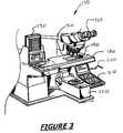
- FIG. 3is an aspect of an embodiment of the present invention showing a microscopy system incorporating the use of a Radio Frequency Identifier Device (RFID) system, according to the present invention.
- RFIDRadio Frequency Identifier Device
- FIG. 4is another aspect of an embodiment of the present invention showing the integration of an RFID device onto a microscope slide, according to the present invention.
- FIG. 1shows an embodiment of a system 10 involving an assembly of components for locating an object 20 as well as any position or point 30 along or on the object
- the objectcould be any animate or inanimate object having a body.
- the objectis a tag, preferably an electronic tag comprising a radio frequency identifier device (RFID).
- RFIDradio frequency identifier device
- the tagis configured to operate cooperatively with an assembly of devices, such as 40 , 50 and 60 , positioned remotely as shown in FIG. 1 .
- Each deviceis capable of sensing or reading the RFID and determining the position of the reading source (e.g., electromagnetic beam), on the object by use of the tag as a positional reference point. Then, using a method of triangulation, any point on the object can be determined precisely with the tag as a reference point, as described below.
- the reading sourcee.g., electromagnetic beam
- Method of triangulationinvolves a process by which the location of a radio transmitter is determined by measuring either the radial distance, or the direction, of the received signal at two or three different points.
- the position of tag 40 , and hence that of object 20is determined by measuring the relative time delays in the radio waves 50 ′, 60 ′, 70 ′ between the RFID tag 40 and the three respective sensors 50 , 60 and 70 , as shown in FIG. 1 a .
- directional antennasmay be used at two sensors 80 , 90 to determine the position of the RFID tag 20 , as shown in FIG. 1 b .
- Directional antennasemit a directional signal with two parts, known as the reference phase signal and the variable phase signal.
- the directional signalis transmitted in such a way that the electrical phase angle between the two components differs by the exact number of degrees that the receiving tag is away from a predetermined radial from the antenna. It will be appreciated by those skilled in the art that, in this manner, the positions of points 30 on object 20 relative to the position of tag 40 can be determined with high accuracy and the conventional systems for monitoring movements using linear or rotary encoders may be replaced with the RFID system of the present invention.
- the RFID system of the present inventionoperates cooperatively incorporating an antenna or flat coil, a transceiver with a decoder and a radio frequency (RF) tag electronically programmed with unique information.
- antenna 100is packaged together with transceiver 110 and decoder 120 to become a reader sensor, also known as interrogator 130 .
- Antenna 100performs the function of a conduit between RF tag 40 and transceiver 110 , which controls the system's data acquisition and communication.
- Antenna 100emits electromagnetic radio signals to activate tag 40 and read the positional data of the tag.
- the tagmay also include information regarding the identification of a particular object 20 , such as a serial number, or other information pertaining to the object.
- the readerdecodes the data encoded in the tag's integrated circuit (silicon chip) and the data is passed onto a microprocessor in host computer 140 shown in FIG. 2 .
- the presence of the electromagnetic field emitted by the antennacan be continuous during the operation of the microscopy. Where constant interrogation is not required, the field can be activated by a sensor under the control of the computer 140 .
- informationcan be both written and read onto the tag remotely by sensor(s) 130 .
- the RFID tag 40 of the present inventioncomprise a passive tag without a separate external power source and obtain operating power generated from the reader sensor 130 . It is also preferred that the frequency range is in between about 30 KHz and 500 KHz, though high-frequency ranges of between about 850 MHz to 950 MHz and 2.4 GHz to 2.5 GHz may also be used in applications for higher read ranges.
- RFIDRadio Frequency Identifier Devices
- the tagsmay include information as an aid in characterizing the objects further, For example, a tag on a piece of lumber, among many others in a lumberyard say, would help locate that lumber as well as providing processing instructions as to what shape and dimensions it should be cut.
- RFID tagsas disclosed below, especially in laboratory microscopy, provides significant advantages over conventional methods of locating and identifying objects.
- the method and systememploy a microscope slide having incorporated thereon a radio frequency identifier device (RFID) and a RFID reader capable of reading the RFID and determining position of the reading source, e.g., electromagnetic beam, on the microscope slide by use of the RFID as a positional reference point.
- RFIDradio frequency identifier device
- the system and methodhave several uses, including automated/fast Fluorescence in situ Hybridization, to determine from which such biological material was harvested, to repeatedly determine the position of material on the microscope slide preferably in an automated manner.
- the disclosed system and methodgreatly reduces the time that is typically spent in reviewing biological material specimens under the microscope.
- FIG. 3shows a portion of a microscope 150 used in a clinical laboratory for analysis of biological specimens deposited on a microscopy slide.
- Microscope 150typically includes an eye-piece 160 , objective lens 170 , a microscope stage 180 on which a microscope slide 190 is mounted. The stage can be positioned under the microscope either manually by moving a lever 200 or by using a control panel 210 programmed to perform such functions.
- Microscope 150 and its associated accessoriesincluding a multiple slide loading system, such as a cassette 230 for example, may be an integral part of console 220 , as shown in FIG. 3 .
- a multiple slide loading systemsuch as a cassette 230 for example
- FIG. 4incorporates a plurality of sensors 240 ′, 240 ′′, 240 ′′′ that operate cooperatively with an electronic tag 191 integrated onto the microscope slide 190 of the present invention.
- Tag 190comprises a radio frequency identifier (RFID) device.
- Slide 190includes an elongate first region 193 and a second region 195 .
- a biological specimen 197is centrally positioned in region 193 and RF tag 191 is located in region 195 .
- the microscope slide and a cover slip(not shown), which overlies the specimen, comprise glass although plastic can also be used.
- Sensors 240may be configured in areas including on and around console 220 of FIG. 3 , but within proximity of RFID tag 191 .
- Sensors 240have the capability of sensing the relative location of tag 191 independent of each other so that the location of the tag, and hence that of slide 190 on microscope stage 180 can be determined relative to the objective lens 170 of microscope 150 of FIG. 3 , using a method of triangulation as described above.
- An additional reference sensor 241can be used for added accuracy and serve as a backup.
- a plurality of microscope slides 190are tagged with RFIDs 191 bearing information corresponding to a unique ID (identification) of the specimens that will be mounted on the slides.
- the radio frequency emitting component of the RFIDs as well as the unique ID informationmay be formed on a silicon chip using any one of the well-known integrated circuit (IC) chip technologies, and the chip mounted onto the slide by using surface mount technologies also known in the art. It is preferred that the ID information for each of the slides is entered into a data base in a computer associated with the microscope system 150 shown in FIG. 3 . In a separate operation (not shown), a plurality of biological specimens are mounted onto slides having the correspondingly tagged information.
- the slidesare then loaded into a cassette 230 or other carrier (e.g., a rack or carrousel).
- the slidesare then fed onto the microscope stage 180 , either sequentially or in another sequence as commanded by a computer.
- a slideAs a slide is positioned on the microscope stage, it becomes into view of a plurality of sensors, and its position is automatically calculated using either one of the methods shown in FIGS. 1 a and 1 b .
- the position of the slide on the stageis transmitted to the computer.
- the slidecan then be moved in any direction, including lateral and vertical directions (x, y and z) under the microscope for examination of the biological sample.
- the movement of the stagecan follow a preprogrammed sequence automatically, or follow the command from an operator operating a key board, or a control panel 210 such as shown in FIG. 3 .
- the position of the stage and hence that of the microscope slidecan be monitored continuously or incrementally by the sensor readers in reference to the RFID, and any observed phenomenon (for example, abnormalities) under the microscope can be entered into the computer at the corresponding locations of biological specimens.
- images of expected abnormalitiescan be stored in a data base in the computer, and any such matching abnormalities that are encountered in biological cells, for example, can be automatically recorded at their respective locations.
- a particular cell of a particular abnormalitycan then be brought into view under the microscope instantly and automatically using the RFID triangulation system and methodology of the present invention.
- the RFID systemcan also be used as a quality assurance system in process oriented environments.
- certain reagentsneed to be kept in controlled environmental conditions, e.g., in refrigerators.
- Vials containing such reagentshave to be removed from the refrigerator for small periods of time. This removal from controlled environment often affects the quality of the reagent as temperature changes alter its chemical or biological consistency.
- Vials bearing RFID tagscan be automatically monitored using a network of sensors in a laboratory environment. The system can keep track of the temperature change cycles and signal to the user so that appropriate measures are taken with the particular vial.
- the RFID systemcan also be used in a number of situations where accurately locating an RFID-tagged item is important.
- An exampleis a security system for identifying the position of a particular item in a closed system, such as passengers and their own luggage in an airplane.
- an RFID tag on the passenger ticket and labels attached to the luggagecan connect passengers with their pieces of luggage.
- a network of sensors positioned in the cabin of an airlinercan record all pieces of luggage entering the cabin and relate them to the individual passenger through his/her ticket tag. Luggage identity can be checked against records from the passenger check-in, while unregistered pieces of luggage will be identifiable when a passenger enters the airplane.
- the tagscan be updated when a particular piece of luggage passes through a security check. In this manner, the exact location of all pieces of luggage in the airplane will be known.
- the systemcan immediately signal for items left behind when passengers deplane without them.
Landscapes
- Physics & Mathematics (AREA)
- Chemical & Material Sciences (AREA)
- Analytical Chemistry (AREA)
- General Physics & Mathematics (AREA)
- Health & Medical Sciences (AREA)
- Engineering & Computer Science (AREA)
- General Health & Medical Sciences (AREA)
- Optics & Photonics (AREA)
- Multimedia (AREA)
- Pathology (AREA)
- Primary Health Care (AREA)
- Immunology (AREA)
- Life Sciences & Earth Sciences (AREA)
- Chemical Kinetics & Catalysis (AREA)
- Epidemiology (AREA)
- Medical Informatics (AREA)
- Biochemistry (AREA)
- Public Health (AREA)
- Computer Vision & Pattern Recognition (AREA)
- Clinical Laboratory Science (AREA)
- Automatic Analysis And Handling Materials Therefor (AREA)
- Microscoopes, Condenser (AREA)
- Image Analysis (AREA)
- Sampling And Sample Adjustment (AREA)
- Radar Systems Or Details Thereof (AREA)
Abstract
Description
Claims (12)
Priority Applications (1)
| Application Number | Priority Date | Filing Date | Title |
|---|---|---|---|
| US11/693,551US7639139B2 (en) | 2004-06-17 | 2007-03-29 | System for automatically locating and manipulating positions on an object |
Applications Claiming Priority (2)
| Application Number | Priority Date | Filing Date | Title |
|---|---|---|---|
| US10/870,111US7199712B2 (en) | 2004-06-17 | 2004-06-17 | System for automatically locating and manipulating positions on an object |
| US11/693,551US7639139B2 (en) | 2004-06-17 | 2007-03-29 | System for automatically locating and manipulating positions on an object |
Related Parent Applications (1)
| Application Number | Title | Priority Date | Filing Date |
|---|---|---|---|
| US10/870,111ContinuationUS7199712B2 (en) | 2004-06-17 | 2004-06-17 | System for automatically locating and manipulating positions on an object |
Publications (2)
| Publication Number | Publication Date |
|---|---|
| US20080238674A1 US20080238674A1 (en) | 2008-10-02 |
| US7639139B2true US7639139B2 (en) | 2009-12-29 |
Family
ID=35480064
Family Applications (3)
| Application Number | Title | Priority Date | Filing Date |
|---|---|---|---|
| US10/870,111Expired - Fee RelatedUS7199712B2 (en) | 2004-06-17 | 2004-06-17 | System for automatically locating and manipulating positions on an object |
| US11/693,544AbandonedUS20070171070A1 (en) | 2004-06-17 | 2007-03-29 | System for automatically locating and manipulating positions on an object |
| US11/693,551Expired - LifetimeUS7639139B2 (en) | 2004-06-17 | 2007-03-29 | System for automatically locating and manipulating positions on an object |
Family Applications Before (2)
| Application Number | Title | Priority Date | Filing Date |
|---|---|---|---|
| US10/870,111Expired - Fee RelatedUS7199712B2 (en) | 2004-06-17 | 2004-06-17 | System for automatically locating and manipulating positions on an object |
| US11/693,544AbandonedUS20070171070A1 (en) | 2004-06-17 | 2007-03-29 | System for automatically locating and manipulating positions on an object |
Country Status (7)
| Country | Link |
|---|---|
| US (3) | US7199712B2 (en) |
| EP (1) | EP1766590A2 (en) |
| JP (1) | JP2008503723A (en) |
| CN (1) | CN101002236A (en) |
| AU (1) | AU2005264990A1 (en) |
| CA (1) | CA2570704A1 (en) |
| WO (1) | WO2006009728A2 (en) |
Cited By (10)
| Publication number | Priority date | Publication date | Assignee | Title |
|---|---|---|---|---|
| US8459509B2 (en) | 2006-05-25 | 2013-06-11 | Sakura Finetek U.S.A., Inc. | Fluid dispensing apparatus |
| US8580568B2 (en) | 2011-09-21 | 2013-11-12 | Sakura Finetek U.S.A., Inc. | Traceability for automated staining system |
| US8752732B2 (en) | 2011-02-01 | 2014-06-17 | Sakura Finetek U.S.A., Inc. | Fluid dispensing system |
| US8932543B2 (en) | 2011-09-21 | 2015-01-13 | Sakura Finetek U.S.A., Inc. | Automated staining system and reaction chamber |
| US9513303B2 (en) | 2013-03-15 | 2016-12-06 | Abbott Laboratories | Light-blocking system for a diagnostic analyzer |
| US9518899B2 (en) | 2003-08-11 | 2016-12-13 | Sakura Finetek U.S.A., Inc. | Automated reagent dispensing system and method of operation |
| US9632103B2 (en) | 2013-03-15 | 2017-04-25 | Abbott Laboraties | Linear track diagnostic analyzer |
| US9672397B2 (en) | 2006-09-13 | 2017-06-06 | Stryker Combo L.L.C. | Apparatus and methods for monitoring objects in a surgical field |
| US9993820B2 (en) | 2013-03-15 | 2018-06-12 | Abbott Laboratories | Automated reagent manager of a diagnostic analyzer system |
| USD1051399S1 (en) | 2021-02-26 | 2024-11-12 | Stryker Corporation | Reader cradle for a surgical stand |
Families Citing this family (40)
| Publication number | Priority date | Publication date | Assignee | Title |
|---|---|---|---|---|
| US7860727B2 (en) | 2003-07-17 | 2010-12-28 | Ventana Medical Systems, Inc. | Laboratory instrumentation information management and control network |
| US8719053B2 (en) | 2003-07-17 | 2014-05-06 | Ventana Medical Systems, Inc. | Laboratory instrumentation information management and control network |
| US7767152B2 (en)* | 2003-08-11 | 2010-08-03 | Sakura Finetek U.S.A., Inc. | Reagent container and slide reaction retaining tray, and method of operation |
| US7058378B2 (en)* | 2003-11-18 | 2006-06-06 | Interdigital Technology Corporation | Method and apparatus for automatic frequency correction of a local oscilator with an error signal derived from an angle value of the conjugate product and sum of block correlator outputs |
| JP4123195B2 (en)* | 2004-06-22 | 2008-07-23 | オムロン株式会社 | Tag communication device, tag communication device control method, tag communication control program, and tag communication management system |
| AU2005259981B2 (en)* | 2004-06-29 | 2012-01-12 | Dako Denmark A/S | Method of pre-treatment and staining of and support device for a biological sample |
| WO2006037151A2 (en)* | 2004-10-08 | 2006-04-13 | Silverbrook Research Pty Ltd | Method of removing polymer coating from an etched trench |
| US20060239867A1 (en)* | 2005-04-01 | 2006-10-26 | Charles Schaeffer | Radio frequency identification (RFID) in laboratories |
| KR100772500B1 (en)* | 2005-06-03 | 2007-11-01 | 한국전자통신연구원 | Radio wave identification sensor and object location tracking device and method using same |
| JP4636321B2 (en)* | 2005-06-07 | 2011-02-23 | ソニー株式会社 | Information processing system and method, and information providing apparatus and method |
| US20070073513A1 (en)* | 2005-09-29 | 2007-03-29 | Joshua Posamentier | Determining RFID tag location |
| TWI272932B (en)* | 2005-12-16 | 2007-02-11 | Radiant Innovation Inc | Ear thermometer with the function of reading radio frequency identification |
| US7616113B2 (en)* | 2007-01-04 | 2009-11-10 | International Business Machines Corporation | Spatially locating RFID tags using multiple readers and correction factors |
| FR2914435B1 (en)* | 2007-03-28 | 2009-05-22 | Steelcase Sa | SYSTEM FOR PROVIDING INFORMATION ON FURNITURE PARTS. |
| US8253557B2 (en)* | 2007-08-07 | 2012-08-28 | Nasser Ani | System and method for tracking luggage |
| CN101828307A (en) | 2007-09-11 | 2010-09-08 | Rf控制有限责任公司 | Radiofrequency signal is obtained and source location system |
| US8988284B2 (en)* | 2008-08-14 | 2015-03-24 | Barry Brucker | System and method for tracking lost subjects |
| US8384522B2 (en)* | 2008-09-03 | 2013-02-26 | Commscope, Inc. Of North Carolina | Radio frequency identification triangulation systems for communications patching systems and related methods of determining patch cord connectivity information |
| US8120488B2 (en)* | 2009-02-27 | 2012-02-21 | Rf Controls, Llc | Radio frequency environment object monitoring system and methods of use |
| US8344823B2 (en) | 2009-08-10 | 2013-01-01 | Rf Controls, Llc | Antenna switching arrangement |
| CN102483809B (en)* | 2009-09-10 | 2015-01-21 | Rf控制有限责任公司 | Calibration and operational assurance method and apparatus for rfid object monitoring systems |
| CN103008036B (en)* | 2012-11-26 | 2014-12-10 | 苏州大学 | Automatic storage and withdrawing and recognition system for cryopreservation tube |
| KR20150122139A (en) | 2013-02-22 | 2015-10-30 | 베크만 컬터, 인코포레이티드 | Rack orientation detection with multiple tags |
| CN103246812A (en)* | 2013-05-12 | 2013-08-14 | 无锡同春新能源科技有限公司 | Radio frequency identification device (RFID) system powered by lithium ion battery and used for storing individual tuberculosis information |
| CN103837977A (en)* | 2014-01-16 | 2014-06-04 | 麦克奥迪实业集团有限公司 | Microscopy device with NFC modules |
| US10579959B2 (en) | 2014-09-10 | 2020-03-03 | Cerner Innovation, Inc. | Intelligent routing of radio-frequency identification data |
| EP3292422B1 (en)* | 2015-05-05 | 2020-01-15 | Xplored S.R.L. | Contactless detection system of the position of objects on a surface |
| US10591592B2 (en) | 2015-06-15 | 2020-03-17 | Humatics Corporation | High-precision time of flight measurement systems |
| CN107949766A (en)* | 2015-06-15 | 2018-04-20 | 修麦提克斯公司 | High-precision time-of-flight measurement system |
| US10665923B2 (en) | 2015-12-17 | 2020-05-26 | Humatics Corporation | Chip-scale radio-frequency localization devices and associated systems and methods |
| US20180111699A1 (en) | 2016-10-21 | 2018-04-26 | Karam Osama Karam IMSEEH | Tagless baggage tracking system and method |
| US10176349B1 (en)* | 2017-12-07 | 2019-01-08 | Kacchip, LLC | Indoor position and vector tracking system and method |
| AU2019206456B2 (en)* | 2018-01-11 | 2021-10-07 | Shell Internationale Research Maatschappij B.V. | Wireless monitoring and profiling of reactor conditions using plurality of sensor-enabled RFID tags and multiple transceivers |
| US11123946B2 (en)* | 2019-02-07 | 2021-09-21 | K&N Engineering, Inc. | Pleated filter preparation system |
| CN109765684B (en)* | 2019-03-03 | 2022-03-18 | 北京工业大学 | Multi-optical path and multi-directional real-time microscopic imaging system |
| EP3726241A1 (en)* | 2019-04-19 | 2020-10-21 | Siemens Mobility GmbH | Method and system for locating an object |
| CN111524395B (en)* | 2020-04-30 | 2021-07-20 | 成都民航空管科技发展有限公司 | A kind of secondary radar transponder code automatic allocation method and system |
| US12080415B2 (en) | 2020-10-09 | 2024-09-03 | Humatics Corporation | Radio-frequency systems and methods for co-localization of medical devices and patients |
| CN114543789B (en)* | 2021-12-27 | 2024-05-24 | 浙江众星志连科技有限责任公司 | Star map identification method and system based on one-dimensional convolutional neural network |
| CN115684165B (en)* | 2023-01-04 | 2023-03-31 | 湖南军芃科技股份有限公司 | Positioning method of glass slide detector, detector and glass slide |
Citations (26)
| Publication number | Priority date | Publication date | Assignee | Title |
|---|---|---|---|---|
| US4183614A (en) | 1977-01-10 | 1980-01-15 | Liquidata, Inc. | Microscope slide |
| US4190314A (en) | 1973-07-13 | 1980-02-26 | Stephen Goldsmith | Microscope and microscope slide for cytological analysis |
| US4513438A (en) | 1982-04-15 | 1985-04-23 | Coulter Electronics, Inc. | Automated microscopy system and method for locating and re-locating objects in an image |
| US4651203A (en) | 1985-10-29 | 1987-03-17 | At&T Technologies, Inc. | Video controlled article positioning system |
| US5602674A (en) | 1993-07-09 | 1997-02-11 | Compucyte Corp. | Computerized specimen encoder |
| US5694212A (en) | 1995-06-20 | 1997-12-02 | Compucyte Corporation | Method for calibrating specimen with specimen holder of a microscope |
| US5812312A (en) | 1997-09-04 | 1998-09-22 | Lorincz; Andrew Endre | Microscope slide |
| US5963368A (en) | 1995-09-15 | 1999-10-05 | Accumed International, Inc. | Specimen management system |
| US6006140A (en) | 1995-03-06 | 1999-12-21 | Perkin-Elmer Ltd. | Infrared microscope stage control |
| US6104291A (en) | 1998-01-09 | 2000-08-15 | Intermec Ip Corp. | Method and apparatus for testing RFID tags |
| US6236223B1 (en) | 1998-11-09 | 2001-05-22 | Intermec Ip Corp. | Method and apparatus for wireless radio frequency testing of RFID integrated circuits |
| US20020030598A1 (en) | 2000-02-17 | 2002-03-14 | Dombrowski Scott A. | Radio frequency label for multiwell plates or slides |
| US20020061127A1 (en)* | 1996-08-23 | 2002-05-23 | Bacus Research Laboratories, Inc. | Apparatus for remote control of a microscope |
| US6567214B2 (en) | 1997-09-04 | 2003-05-20 | Andrew E. Lorincz | Microscope slide having culture media and method for use |
| US6714121B1 (en) | 1999-08-09 | 2004-03-30 | Micron Technology, Inc. | RFID material tracking method and apparatus |
| US6750769B1 (en) | 2002-12-12 | 2004-06-15 | Sun Microsystems, Inc. | Method and apparatus for using RFID tags to determine the position of an object |
| US20040114218A1 (en)* | 2001-04-12 | 2004-06-17 | Adam Karlsson | Method in microscopy and a microscope, where subimages are recorded and puzzled in the same coordinate system to enable a precise positioning of the microscope stage |
| US20050051614A1 (en) | 2003-09-05 | 2005-03-10 | Cytyc Corporation | Locally storing biological specimen data to a slide |
| JP2005128868A (en) | 2003-10-24 | 2005-05-19 | Toshiba Teli Corp | Radio-tagged object, and method and device for specifying it |
| US20050123181A1 (en) | 2003-10-08 | 2005-06-09 | Philip Freund | Automated microscope slide tissue sample mapping and image acquisition |
| US20050242957A1 (en) | 2004-04-30 | 2005-11-03 | Kimberly-Clark Worldwide, Inc. | Deactivating a data tag for user privacy or tamper-evident packaging |
| WO2005121865A1 (en) | 2004-06-12 | 2005-12-22 | Leica Microsystems Cms Gmbh | Object support device which is used to receive an object which is to be analysed or examined by a microscope or by a laboratory analysis system |
| US7023356B2 (en) | 2001-11-26 | 2006-04-04 | Aero-Vision Technologies, Inc. | System and method for monitoring individuals and objects associated with wireless identification tags |
| US7030736B2 (en) | 2004-06-03 | 2006-04-18 | Brunswick Bowling & Billiards Corporation | Radio frequency identification (RFID) pin detection system |
| US7167305B2 (en)* | 2002-07-30 | 2007-01-23 | Nikon Corporation | Microscope system |
| US7215467B2 (en)* | 2001-03-01 | 2007-05-08 | Olympus Corporation | System and method for controlling microscope |
Family Cites Families (9)
| Publication number | Priority date | Publication date | Assignee | Title |
|---|---|---|---|---|
| US5428690A (en)* | 1991-09-23 | 1995-06-27 | Becton Dickinson And Company | Method and apparatus for automated assay of biological specimens |
| JPH06250094A (en)* | 1993-02-25 | 1994-09-09 | Nikon Corp | Method and device for positioning microscope slide glass |
| US5933079A (en)* | 1995-09-01 | 1999-08-03 | Remote Data Systems, Inc. | Signal discriminator and positioning system |
| JP4332905B2 (en)* | 1998-02-12 | 2009-09-16 | 株式会社ニコン | Microscope system |
| JP3078529B2 (en)* | 1998-10-05 | 2000-08-21 | ローム株式会社 | IC tag and tag detection system |
| WO2002037158A2 (en)* | 2000-11-03 | 2002-05-10 | Cytyc Corporation | Cytological imaging systems and methods |
| JP4227869B2 (en)* | 2002-09-09 | 2009-02-18 | 株式会社エスアールエル | Glass slide |
| JP4307815B2 (en)* | 2002-10-10 | 2009-08-05 | オリンパス株式会社 | Confocal laser scanning microscope apparatus and program thereof |
| US7223320B2 (en)* | 2003-06-12 | 2007-05-29 | Symbol Technologies, Inc. | Method and apparatus for expanding a semiconductor wafer |
- 2004
- 2004-06-17USUS10/870,111patent/US7199712B2/ennot_activeExpired - Fee Related
- 2005
- 2005-06-16JPJP2007516675Apatent/JP2008503723A/enactivePending
- 2005-06-16WOPCT/US2005/021106patent/WO2006009728A2/enactiveApplication Filing
- 2005-06-16CACA002570704Apatent/CA2570704A1/ennot_activeAbandoned
- 2005-06-16CNCNA2005800246706Apatent/CN101002236A/enactivePending
- 2005-06-16EPEP05761974Apatent/EP1766590A2/ennot_activeWithdrawn
- 2005-06-16AUAU2005264990Apatent/AU2005264990A1/ennot_activeAbandoned
- 2007
- 2007-03-29USUS11/693,544patent/US20070171070A1/ennot_activeAbandoned
- 2007-03-29USUS11/693,551patent/US7639139B2/ennot_activeExpired - Lifetime
Patent Citations (26)
| Publication number | Priority date | Publication date | Assignee | Title |
|---|---|---|---|---|
| US4190314A (en) | 1973-07-13 | 1980-02-26 | Stephen Goldsmith | Microscope and microscope slide for cytological analysis |
| US4183614A (en) | 1977-01-10 | 1980-01-15 | Liquidata, Inc. | Microscope slide |
| US4513438A (en) | 1982-04-15 | 1985-04-23 | Coulter Electronics, Inc. | Automated microscopy system and method for locating and re-locating objects in an image |
| US4651203A (en) | 1985-10-29 | 1987-03-17 | At&T Technologies, Inc. | Video controlled article positioning system |
| US5602674A (en) | 1993-07-09 | 1997-02-11 | Compucyte Corp. | Computerized specimen encoder |
| US6006140A (en) | 1995-03-06 | 1999-12-21 | Perkin-Elmer Ltd. | Infrared microscope stage control |
| US5694212A (en) | 1995-06-20 | 1997-12-02 | Compucyte Corporation | Method for calibrating specimen with specimen holder of a microscope |
| US5963368A (en) | 1995-09-15 | 1999-10-05 | Accumed International, Inc. | Specimen management system |
| US20020061127A1 (en)* | 1996-08-23 | 2002-05-23 | Bacus Research Laboratories, Inc. | Apparatus for remote control of a microscope |
| US5812312A (en) | 1997-09-04 | 1998-09-22 | Lorincz; Andrew Endre | Microscope slide |
| US6567214B2 (en) | 1997-09-04 | 2003-05-20 | Andrew E. Lorincz | Microscope slide having culture media and method for use |
| US6104291A (en) | 1998-01-09 | 2000-08-15 | Intermec Ip Corp. | Method and apparatus for testing RFID tags |
| US6236223B1 (en) | 1998-11-09 | 2001-05-22 | Intermec Ip Corp. | Method and apparatus for wireless radio frequency testing of RFID integrated circuits |
| US6714121B1 (en) | 1999-08-09 | 2004-03-30 | Micron Technology, Inc. | RFID material tracking method and apparatus |
| US20020030598A1 (en) | 2000-02-17 | 2002-03-14 | Dombrowski Scott A. | Radio frequency label for multiwell plates or slides |
| US7215467B2 (en)* | 2001-03-01 | 2007-05-08 | Olympus Corporation | System and method for controlling microscope |
| US20040114218A1 (en)* | 2001-04-12 | 2004-06-17 | Adam Karlsson | Method in microscopy and a microscope, where subimages are recorded and puzzled in the same coordinate system to enable a precise positioning of the microscope stage |
| US7023356B2 (en) | 2001-11-26 | 2006-04-04 | Aero-Vision Technologies, Inc. | System and method for monitoring individuals and objects associated with wireless identification tags |
| US7167305B2 (en)* | 2002-07-30 | 2007-01-23 | Nikon Corporation | Microscope system |
| US6750769B1 (en) | 2002-12-12 | 2004-06-15 | Sun Microsystems, Inc. | Method and apparatus for using RFID tags to determine the position of an object |
| US20050051614A1 (en) | 2003-09-05 | 2005-03-10 | Cytyc Corporation | Locally storing biological specimen data to a slide |
| US20050123181A1 (en) | 2003-10-08 | 2005-06-09 | Philip Freund | Automated microscope slide tissue sample mapping and image acquisition |
| JP2005128868A (en) | 2003-10-24 | 2005-05-19 | Toshiba Teli Corp | Radio-tagged object, and method and device for specifying it |
| US20050242957A1 (en) | 2004-04-30 | 2005-11-03 | Kimberly-Clark Worldwide, Inc. | Deactivating a data tag for user privacy or tamper-evident packaging |
| US7030736B2 (en) | 2004-06-03 | 2006-04-18 | Brunswick Bowling & Billiards Corporation | Radio frequency identification (RFID) pin detection system |
| WO2005121865A1 (en) | 2004-06-12 | 2005-12-22 | Leica Microsystems Cms Gmbh | Object support device which is used to receive an object which is to be analysed or examined by a microscope or by a laboratory analysis system |
Cited By (23)
| Publication number | Priority date | Publication date | Assignee | Title |
|---|---|---|---|---|
| US9518899B2 (en) | 2003-08-11 | 2016-12-13 | Sakura Finetek U.S.A., Inc. | Automated reagent dispensing system and method of operation |
| US8459509B2 (en) | 2006-05-25 | 2013-06-11 | Sakura Finetek U.S.A., Inc. | Fluid dispensing apparatus |
| US9914124B2 (en) | 2006-05-25 | 2018-03-13 | Sakura Finetek U.S.A., Inc. | Fluid dispensing apparatus |
| US10729510B2 (en) | 2006-09-13 | 2020-08-04 | Stryker Corporation | Apparatus and methods for monitoring objects in a surgical field |
| US11963827B2 (en) | 2006-09-13 | 2024-04-23 | Stryker Corporation | Apparatus and methods for monitoring objects in a surgical field |
| US12357412B2 (en) | 2006-09-13 | 2025-07-15 | Stryker Corporation | Apparatus and methods for monitoring objects in a surgical field |
| US11793591B2 (en) | 2006-09-13 | 2023-10-24 | Stryker Corporation | Apparatus and methods for monitoring objects in a surgical field |
| US11116598B1 (en) | 2006-09-13 | 2021-09-14 | Stryker Corporation | Apparatus and methods for monitoring objects in a surgical field |
| US9672397B2 (en) | 2006-09-13 | 2017-06-06 | Stryker Combo L.L.C. | Apparatus and methods for monitoring objects in a surgical field |
| US9974625B2 (en) | 2006-09-13 | 2018-05-22 | Stryker Combo L.L.C. | Apparatus and methods for monitoring objects in a surgical field |
| US11090129B2 (en) | 2006-09-13 | 2021-08-17 | Stryker Corporation | Apparatus and methods for monitoring objects in a surgical field |
| US9016526B2 (en) | 2011-02-01 | 2015-04-28 | Sakura Finetek U.S.A., Inc. | Fluid dispensing system |
| US8752732B2 (en) | 2011-02-01 | 2014-06-17 | Sakura Finetek U.S.A., Inc. | Fluid dispensing system |
| US8932543B2 (en) | 2011-09-21 | 2015-01-13 | Sakura Finetek U.S.A., Inc. | Automated staining system and reaction chamber |
| US10295444B2 (en) | 2011-09-21 | 2019-05-21 | Sakura Finetek U.S.A., Inc. | Automated staining system and reaction chamber |
| US8580568B2 (en) | 2011-09-21 | 2013-11-12 | Sakura Finetek U.S.A., Inc. | Traceability for automated staining system |
| US12281970B2 (en) | 2011-09-21 | 2025-04-22 | Sakura Finetek U.S.A., Inc. | Automated staining system and reaction chamber |
| US9005980B2 (en) | 2011-09-21 | 2015-04-14 | Sakura Finetek U.S.A., Inc. | Traceability for automated staining system |
| US9632103B2 (en) | 2013-03-15 | 2017-04-25 | Abbott Laboraties | Linear track diagnostic analyzer |
| US10330691B2 (en) | 2013-03-15 | 2019-06-25 | Abbott Laboratories | Light-blocking system for a diagnostic analyzer |
| US9993820B2 (en) | 2013-03-15 | 2018-06-12 | Abbott Laboratories | Automated reagent manager of a diagnostic analyzer system |
| US9513303B2 (en) | 2013-03-15 | 2016-12-06 | Abbott Laboratories | Light-blocking system for a diagnostic analyzer |
| USD1051399S1 (en) | 2021-02-26 | 2024-11-12 | Stryker Corporation | Reader cradle for a surgical stand |
Also Published As
| Publication number | Publication date |
|---|---|
| AU2005264990A1 (en) | 2006-01-26 |
| JP2008503723A (en) | 2008-02-07 |
| US20050280574A1 (en) | 2005-12-22 |
| WO2006009728A2 (en) | 2006-01-26 |
| CA2570704A1 (en) | 2006-01-26 |
| US20080238674A1 (en) | 2008-10-02 |
| CN101002236A (en) | 2007-07-18 |
| US7199712B2 (en) | 2007-04-03 |
| US20070171070A1 (en) | 2007-07-26 |
| WO2006009728A3 (en) | 2006-11-30 |
| EP1766590A2 (en) | 2007-03-28 |
Similar Documents
| Publication | Publication Date | Title |
|---|---|---|
| US7639139B2 (en) | System for automatically locating and manipulating positions on an object | |
| US20080239478A1 (en) | System for automatically locating and manipulating positions on an object | |
| US7760428B2 (en) | Specimen slide unit for holding a specimen that is to be examined under a microscope or analyzed with a laboratory analysis system | |
| JP4772153B2 (en) | Apparatus and method for verifying the location of a region of interest in a sample in an image generation system | |
| US7083106B2 (en) | Locally storing biological specimen data to a slide | |
| US8969087B2 (en) | Method of pre-treatment and staining of a biological sample and device for support of a biological sample and methods of using such device | |
| US7006674B1 (en) | Apparatus and methods for verifying the location of areas of interest within a sample in an imaging system | |
| JP4673989B2 (en) | Device for manipulating and / or processing objects, preferably automatically | |
| US20080305515A1 (en) | Pathology Sample Processing Workstation | |
| US20170220995A1 (en) | System for Recording an Inventory of Monitoring Objects of a Plant | |
| JP3890277B2 (en) | Specimen instruction information creation system | |
| US7405056B2 (en) | Tissue punch and tissue sample labeling methods and devices for microarray preparation, archiving and documentation | |
| US9418321B1 (en) | Tagging of tissue carriers with light-activated microtransponders | |
| JP2015200668A (en) | System for tracking liquid containers in automated laboratory analyzers by radio frequency identification | |
| EP3626652B1 (en) | Consumable management system for laboratories | |
| CN110444456B (en) | Apparatus and method for tracking a microscope sample | |
| US10109376B2 (en) | Measuring apparatus | |
| EP3514550A1 (en) | Pcr tube, rfid specimen managing system, and rfid specimen managing method | |
| EP3199953B1 (en) | Method for teaching positioning of a bar code scanner and apparatus for processing a sample or reagent | |
| HK1235856A1 (en) | Drawer vision system |
Legal Events
| Date | Code | Title | Description |
|---|---|---|---|
| STCF | Information on status: patent grant | Free format text:PATENTED CASE | |
| REMI | Maintenance fee reminder mailed | ||
| FPAY | Fee payment | Year of fee payment:4 | |
| SULP | Surcharge for late payment | ||
| REMI | Maintenance fee reminder mailed | ||
| FEPP | Fee payment procedure | Free format text:7.5 YR SURCHARGE - LATE PMT W/IN 6 MO, SMALL ENTITY (ORIGINAL EVENT CODE: M2555) | |
| MAFP | Maintenance fee payment | Free format text:PAYMENT OF MAINTENANCE FEE, 8TH YR, SMALL ENTITY (ORIGINAL EVENT CODE: M2552) Year of fee payment:8 | |
| AS | Assignment | Owner name:IKONISYS, INC., CONNECTICUT Free format text:ASSIGNMENT OF ASSIGNORS INTEREST;ASSIGNORS:TAFAS, TRIANTAFYLLOS P;KIM, YOUNGMIN;REEL/FRAME:048367/0296 Effective date:20190219 | |
| AS | Assignment | Owner name:IKONISYS, INC., CONNECTICUT Free format text:CORRECTIVE ASSIGNMENT TO CORRECT THE REPLACE YOUNGMIN KIM EMPLOYMENT AGREEMENT DOCUMENT PREVIOUSLY RECORDED AT REEL: 048367 FRAME: 0296. ASSIGNOR(S) HEREBY CONFIRMS THE ASSIGNMENT;ASSIGNORS:TAFAS, TRIANTAFYLLOS P;KIM, YOUNGMIN;REEL/FRAME:048414/0658 Effective date:20190219 | |
| FEPP | Fee payment procedure | Free format text:MAINTENANCE FEE REMINDER MAILED (ORIGINAL EVENT CODE: REM.); ENTITY STATUS OF PATENT OWNER: SMALL ENTITY | |
| LAPS | Lapse for failure to pay maintenance fees | Free format text:PATENT EXPIRED FOR FAILURE TO PAY MAINTENANCE FEES (ORIGINAL EVENT CODE: EXP.); ENTITY STATUS OF PATENT OWNER: SMALL ENTITY | |
| STCH | Information on status: patent discontinuation | Free format text:PATENT EXPIRED DUE TO NONPAYMENT OF MAINTENANCE FEES UNDER 37 CFR 1.362 | |
| FP | Lapsed due to failure to pay maintenance fee | Effective date:20211229 | |
| PRDP | Patent reinstated due to the acceptance of a late maintenance fee | Effective date:20220626 | |
| FEPP | Fee payment procedure | Free format text:PETITION RELATED TO MAINTENANCE FEES FILED (ORIGINAL EVENT CODE: PMFP); ENTITY STATUS OF PATENT OWNER: SMALL ENTITY Free format text:PETITION RELATED TO MAINTENANCE FEES GRANTED (ORIGINAL EVENT CODE: PMFG); ENTITY STATUS OF PATENT OWNER: SMALL ENTITY Free format text:SURCHARGE, PETITION TO ACCEPT PYMT AFTER EXP, UNINTENTIONAL. (ORIGINAL EVENT CODE: M2558); ENTITY STATUS OF PATENT OWNER: SMALL ENTITY | |
| MAFP | Maintenance fee payment | Free format text:PAYMENT OF MAINTENANCE FEE, 12TH YR, SMALL ENTITY (ORIGINAL EVENT CODE: M2553); ENTITY STATUS OF PATENT OWNER: SMALL ENTITY Year of fee payment:12 | |
| STCF | Information on status: patent grant | Free format text:PATENTED CASE |