US7637959B2 - Systems and methods for adjusting the angle of a prosthetic ankle based on a measured surface angle - Google Patents
Systems and methods for adjusting the angle of a prosthetic ankle based on a measured surface angleDownload PDFInfo
- Publication number
- US7637959B2 US7637959B2US11/367,048US36704806AUS7637959B2US 7637959 B2US7637959 B2US 7637959B2US 36704806 AUS36704806 AUS 36704806AUS 7637959 B2US7637959 B2US 7637959B2
- Authority
- US
- United States
- Prior art keywords
- angle
- ankle
- lower limb
- prosthetic
- foot unit
- Prior art date
- Legal status (The legal status is an assumption and is not a legal conclusion. Google has not performed a legal analysis and makes no representation as to the accuracy of the status listed.)
- Active, expires
Links
Images


Classifications
- A—HUMAN NECESSITIES
- A61—MEDICAL OR VETERINARY SCIENCE; HYGIENE
- A61F—FILTERS IMPLANTABLE INTO BLOOD VESSELS; PROSTHESES; DEVICES PROVIDING PATENCY TO, OR PREVENTING COLLAPSING OF, TUBULAR STRUCTURES OF THE BODY, e.g. STENTS; ORTHOPAEDIC, NURSING OR CONTRACEPTIVE DEVICES; FOMENTATION; TREATMENT OR PROTECTION OF EYES OR EARS; BANDAGES, DRESSINGS OR ABSORBENT PADS; FIRST-AID KITS
- A61F2/00—Filters implantable into blood vessels; Prostheses, i.e. artificial substitutes or replacements for parts of the body; Appliances for connecting them with the body; Devices providing patency to, or preventing collapsing of, tubular structures of the body, e.g. stents
- A61F2/50—Prostheses not implantable in the body
- A61F2/60—Artificial legs or feet or parts thereof
- A61F2/66—Feet; Ankle joints
- A—HUMAN NECESSITIES
- A61—MEDICAL OR VETERINARY SCIENCE; HYGIENE
- A61F—FILTERS IMPLANTABLE INTO BLOOD VESSELS; PROSTHESES; DEVICES PROVIDING PATENCY TO, OR PREVENTING COLLAPSING OF, TUBULAR STRUCTURES OF THE BODY, e.g. STENTS; ORTHOPAEDIC, NURSING OR CONTRACEPTIVE DEVICES; FOMENTATION; TREATMENT OR PROTECTION OF EYES OR EARS; BANDAGES, DRESSINGS OR ABSORBENT PADS; FIRST-AID KITS
- A61F2/00—Filters implantable into blood vessels; Prostheses, i.e. artificial substitutes or replacements for parts of the body; Appliances for connecting them with the body; Devices providing patency to, or preventing collapsing of, tubular structures of the body, e.g. stents
- A61F2/50—Prostheses not implantable in the body
- A61F2/68—Operating or control means
- A61F2/70—Operating or control means electrical
- A—HUMAN NECESSITIES
- A61—MEDICAL OR VETERINARY SCIENCE; HYGIENE
- A61F—FILTERS IMPLANTABLE INTO BLOOD VESSELS; PROSTHESES; DEVICES PROVIDING PATENCY TO, OR PREVENTING COLLAPSING OF, TUBULAR STRUCTURES OF THE BODY, e.g. STENTS; ORTHOPAEDIC, NURSING OR CONTRACEPTIVE DEVICES; FOMENTATION; TREATMENT OR PROTECTION OF EYES OR EARS; BANDAGES, DRESSINGS OR ABSORBENT PADS; FIRST-AID KITS
- A61F2/00—Filters implantable into blood vessels; Prostheses, i.e. artificial substitutes or replacements for parts of the body; Appliances for connecting them with the body; Devices providing patency to, or preventing collapsing of, tubular structures of the body, e.g. stents
- A61F2/50—Prostheses not implantable in the body
- A61F2/60—Artificial legs or feet or parts thereof
- A61F2/66—Feet; Ankle joints
- A61F2/6607—Ankle joints
- A—HUMAN NECESSITIES
- A61—MEDICAL OR VETERINARY SCIENCE; HYGIENE
- A61F—FILTERS IMPLANTABLE INTO BLOOD VESSELS; PROSTHESES; DEVICES PROVIDING PATENCY TO, OR PREVENTING COLLAPSING OF, TUBULAR STRUCTURES OF THE BODY, e.g. STENTS; ORTHOPAEDIC, NURSING OR CONTRACEPTIVE DEVICES; FOMENTATION; TREATMENT OR PROTECTION OF EYES OR EARS; BANDAGES, DRESSINGS OR ABSORBENT PADS; FIRST-AID KITS
- A61F2/00—Filters implantable into blood vessels; Prostheses, i.e. artificial substitutes or replacements for parts of the body; Appliances for connecting them with the body; Devices providing patency to, or preventing collapsing of, tubular structures of the body, e.g. stents
- A61F2/50—Prostheses not implantable in the body
- A61F2/68—Operating or control means
- A61F2/70—Operating or control means electrical
- A61F2/72—Bioelectric control, e.g. myoelectric
- A—HUMAN NECESSITIES
- A61—MEDICAL OR VETERINARY SCIENCE; HYGIENE
- A61F—FILTERS IMPLANTABLE INTO BLOOD VESSELS; PROSTHESES; DEVICES PROVIDING PATENCY TO, OR PREVENTING COLLAPSING OF, TUBULAR STRUCTURES OF THE BODY, e.g. STENTS; ORTHOPAEDIC, NURSING OR CONTRACEPTIVE DEVICES; FOMENTATION; TREATMENT OR PROTECTION OF EYES OR EARS; BANDAGES, DRESSINGS OR ABSORBENT PADS; FIRST-AID KITS
- A61F2/00—Filters implantable into blood vessels; Prostheses, i.e. artificial substitutes or replacements for parts of the body; Appliances for connecting them with the body; Devices providing patency to, or preventing collapsing of, tubular structures of the body, e.g. stents
- A61F2/50—Prostheses not implantable in the body
- A61F2002/5016—Prostheses not implantable in the body adjustable
- A61F2002/5018—Prostheses not implantable in the body adjustable for adjusting angular orientation
- A—HUMAN NECESSITIES
- A61—MEDICAL OR VETERINARY SCIENCE; HYGIENE
- A61F—FILTERS IMPLANTABLE INTO BLOOD VESSELS; PROSTHESES; DEVICES PROVIDING PATENCY TO, OR PREVENTING COLLAPSING OF, TUBULAR STRUCTURES OF THE BODY, e.g. STENTS; ORTHOPAEDIC, NURSING OR CONTRACEPTIVE DEVICES; FOMENTATION; TREATMENT OR PROTECTION OF EYES OR EARS; BANDAGES, DRESSINGS OR ABSORBENT PADS; FIRST-AID KITS
- A61F2/00—Filters implantable into blood vessels; Prostheses, i.e. artificial substitutes or replacements for parts of the body; Appliances for connecting them with the body; Devices providing patency to, or preventing collapsing of, tubular structures of the body, e.g. stents
- A61F2/50—Prostheses not implantable in the body
- A61F2002/5072—Prostheses not implantable in the body having spring elements
- A61F2002/5073—Helical springs, e.g. having at least one helical spring
- A—HUMAN NECESSITIES
- A61—MEDICAL OR VETERINARY SCIENCE; HYGIENE
- A61F—FILTERS IMPLANTABLE INTO BLOOD VESSELS; PROSTHESES; DEVICES PROVIDING PATENCY TO, OR PREVENTING COLLAPSING OF, TUBULAR STRUCTURES OF THE BODY, e.g. STENTS; ORTHOPAEDIC, NURSING OR CONTRACEPTIVE DEVICES; FOMENTATION; TREATMENT OR PROTECTION OF EYES OR EARS; BANDAGES, DRESSINGS OR ABSORBENT PADS; FIRST-AID KITS
- A61F2/00—Filters implantable into blood vessels; Prostheses, i.e. artificial substitutes or replacements for parts of the body; Appliances for connecting them with the body; Devices providing patency to, or preventing collapsing of, tubular structures of the body, e.g. stents
- A61F2/50—Prostheses not implantable in the body
- A61F2/60—Artificial legs or feet or parts thereof
- A61F2/66—Feet; Ankle joints
- A61F2002/6614—Feet
- A61F2002/6642—Heels
- A—HUMAN NECESSITIES
- A61—MEDICAL OR VETERINARY SCIENCE; HYGIENE
- A61F—FILTERS IMPLANTABLE INTO BLOOD VESSELS; PROSTHESES; DEVICES PROVIDING PATENCY TO, OR PREVENTING COLLAPSING OF, TUBULAR STRUCTURES OF THE BODY, e.g. STENTS; ORTHOPAEDIC, NURSING OR CONTRACEPTIVE DEVICES; FOMENTATION; TREATMENT OR PROTECTION OF EYES OR EARS; BANDAGES, DRESSINGS OR ABSORBENT PADS; FIRST-AID KITS
- A61F2/00—Filters implantable into blood vessels; Prostheses, i.e. artificial substitutes or replacements for parts of the body; Appliances for connecting them with the body; Devices providing patency to, or preventing collapsing of, tubular structures of the body, e.g. stents
- A61F2/50—Prostheses not implantable in the body
- A61F2/60—Artificial legs or feet or parts thereof
- A61F2/66—Feet; Ankle joints
- A61F2002/6614—Feet
- A61F2002/6657—Feet having a plate-like or strip-like spring element, e.g. an energy-storing cantilever spring keel
- A61F2002/6685—S-shaped
- A—HUMAN NECESSITIES
- A61—MEDICAL OR VETERINARY SCIENCE; HYGIENE
- A61F—FILTERS IMPLANTABLE INTO BLOOD VESSELS; PROSTHESES; DEVICES PROVIDING PATENCY TO, OR PREVENTING COLLAPSING OF, TUBULAR STRUCTURES OF THE BODY, e.g. STENTS; ORTHOPAEDIC, NURSING OR CONTRACEPTIVE DEVICES; FOMENTATION; TREATMENT OR PROTECTION OF EYES OR EARS; BANDAGES, DRESSINGS OR ABSORBENT PADS; FIRST-AID KITS
- A61F2/00—Filters implantable into blood vessels; Prostheses, i.e. artificial substitutes or replacements for parts of the body; Appliances for connecting them with the body; Devices providing patency to, or preventing collapsing of, tubular structures of the body, e.g. stents
- A61F2/50—Prostheses not implantable in the body
- A61F2/68—Operating or control means
- A61F2/70—Operating or control means electrical
- A61F2002/701—Operating or control means electrical operated by electrically controlled means, e.g. solenoids or torque motors
- A—HUMAN NECESSITIES
- A61—MEDICAL OR VETERINARY SCIENCE; HYGIENE
- A61F—FILTERS IMPLANTABLE INTO BLOOD VESSELS; PROSTHESES; DEVICES PROVIDING PATENCY TO, OR PREVENTING COLLAPSING OF, TUBULAR STRUCTURES OF THE BODY, e.g. STENTS; ORTHOPAEDIC, NURSING OR CONTRACEPTIVE DEVICES; FOMENTATION; TREATMENT OR PROTECTION OF EYES OR EARS; BANDAGES, DRESSINGS OR ABSORBENT PADS; FIRST-AID KITS
- A61F2/00—Filters implantable into blood vessels; Prostheses, i.e. artificial substitutes or replacements for parts of the body; Appliances for connecting them with the body; Devices providing patency to, or preventing collapsing of, tubular structures of the body, e.g. stents
- A61F2/50—Prostheses not implantable in the body
- A61F2/68—Operating or control means
- A61F2/70—Operating or control means electrical
- A61F2002/704—Operating or control means electrical computer-controlled, e.g. robotic control
- A—HUMAN NECESSITIES
- A61—MEDICAL OR VETERINARY SCIENCE; HYGIENE
- A61F—FILTERS IMPLANTABLE INTO BLOOD VESSELS; PROSTHESES; DEVICES PROVIDING PATENCY TO, OR PREVENTING COLLAPSING OF, TUBULAR STRUCTURES OF THE BODY, e.g. STENTS; ORTHOPAEDIC, NURSING OR CONTRACEPTIVE DEVICES; FOMENTATION; TREATMENT OR PROTECTION OF EYES OR EARS; BANDAGES, DRESSINGS OR ABSORBENT PADS; FIRST-AID KITS
- A61F2/00—Filters implantable into blood vessels; Prostheses, i.e. artificial substitutes or replacements for parts of the body; Appliances for connecting them with the body; Devices providing patency to, or preventing collapsing of, tubular structures of the body, e.g. stents
- A61F2/50—Prostheses not implantable in the body
- A61F2/68—Operating or control means
- A61F2/70—Operating or control means electrical
- A61F2002/705—Electromagnetic data transfer
- A—HUMAN NECESSITIES
- A61—MEDICAL OR VETERINARY SCIENCE; HYGIENE
- A61F—FILTERS IMPLANTABLE INTO BLOOD VESSELS; PROSTHESES; DEVICES PROVIDING PATENCY TO, OR PREVENTING COLLAPSING OF, TUBULAR STRUCTURES OF THE BODY, e.g. STENTS; ORTHOPAEDIC, NURSING OR CONTRACEPTIVE DEVICES; FOMENTATION; TREATMENT OR PROTECTION OF EYES OR EARS; BANDAGES, DRESSINGS OR ABSORBENT PADS; FIRST-AID KITS
- A61F2/00—Filters implantable into blood vessels; Prostheses, i.e. artificial substitutes or replacements for parts of the body; Appliances for connecting them with the body; Devices providing patency to, or preventing collapsing of, tubular structures of the body, e.g. stents
- A61F2/50—Prostheses not implantable in the body
- A61F2/76—Means for assembling, fitting or testing prostheses, e.g. for measuring or balancing, e.g. alignment means
- A61F2002/7615—Measuring means
- A61F2002/7625—Measuring means for measuring angular position
- A—HUMAN NECESSITIES
- A61—MEDICAL OR VETERINARY SCIENCE; HYGIENE
- A61F—FILTERS IMPLANTABLE INTO BLOOD VESSELS; PROSTHESES; DEVICES PROVIDING PATENCY TO, OR PREVENTING COLLAPSING OF, TUBULAR STRUCTURES OF THE BODY, e.g. STENTS; ORTHOPAEDIC, NURSING OR CONTRACEPTIVE DEVICES; FOMENTATION; TREATMENT OR PROTECTION OF EYES OR EARS; BANDAGES, DRESSINGS OR ABSORBENT PADS; FIRST-AID KITS
- A61F2/00—Filters implantable into blood vessels; Prostheses, i.e. artificial substitutes or replacements for parts of the body; Appliances for connecting them with the body; Devices providing patency to, or preventing collapsing of, tubular structures of the body, e.g. stents
- A61F2/50—Prostheses not implantable in the body
- A61F2/76—Means for assembling, fitting or testing prostheses, e.g. for measuring or balancing, e.g. alignment means
- A61F2002/7615—Measuring means
- A61F2002/7635—Measuring means for measuring force, pressure or mechanical tension
- A—HUMAN NECESSITIES
- A61—MEDICAL OR VETERINARY SCIENCE; HYGIENE
- A61F—FILTERS IMPLANTABLE INTO BLOOD VESSELS; PROSTHESES; DEVICES PROVIDING PATENCY TO, OR PREVENTING COLLAPSING OF, TUBULAR STRUCTURES OF THE BODY, e.g. STENTS; ORTHOPAEDIC, NURSING OR CONTRACEPTIVE DEVICES; FOMENTATION; TREATMENT OR PROTECTION OF EYES OR EARS; BANDAGES, DRESSINGS OR ABSORBENT PADS; FIRST-AID KITS
- A61F2/00—Filters implantable into blood vessels; Prostheses, i.e. artificial substitutes or replacements for parts of the body; Appliances for connecting them with the body; Devices providing patency to, or preventing collapsing of, tubular structures of the body, e.g. stents
- A61F2/50—Prostheses not implantable in the body
- A61F2/76—Means for assembling, fitting or testing prostheses, e.g. for measuring or balancing, e.g. alignment means
- A61F2002/7615—Measuring means
- A61F2002/764—Measuring means for measuring acceleration
- A—HUMAN NECESSITIES
- A61—MEDICAL OR VETERINARY SCIENCE; HYGIENE
- A61F—FILTERS IMPLANTABLE INTO BLOOD VESSELS; PROSTHESES; DEVICES PROVIDING PATENCY TO, OR PREVENTING COLLAPSING OF, TUBULAR STRUCTURES OF THE BODY, e.g. STENTS; ORTHOPAEDIC, NURSING OR CONTRACEPTIVE DEVICES; FOMENTATION; TREATMENT OR PROTECTION OF EYES OR EARS; BANDAGES, DRESSINGS OR ABSORBENT PADS; FIRST-AID KITS
- A61F2/00—Filters implantable into blood vessels; Prostheses, i.e. artificial substitutes or replacements for parts of the body; Appliances for connecting them with the body; Devices providing patency to, or preventing collapsing of, tubular structures of the body, e.g. stents
- A61F2/50—Prostheses not implantable in the body
- A61F2/76—Means for assembling, fitting or testing prostheses, e.g. for measuring or balancing, e.g. alignment means
- A61F2002/7615—Measuring means
- A61F2002/7645—Measuring means for measuring torque, e.g. hinge or turning moment, moment of force
Definitions
- Preferred embodiments of this inventionrelate to sensing systems and methods for a motion-controlled limb and, in particular, an ankle-motion-controlled foot.
- Orthotic devicesinclude external apparatuses used to support, align, prevent, protect, correct deformities of, or improve the function of movable parts of the body.
- Prosthetic devicesinclude apparatuses used as artificial substitutes for a missing body part, such as an arm or leg.
- one embodiment of the inventionincludes a prosthetic or orthotic system that is self-powered and that mimics the natural movement of a healthy limb, and in particular, the movement of a healthy ankle.
- Another embodiment of the inventionincludes a sensor system and a control system that manage the motion of the prosthetic or orthotic system so as to facilitate movement by the disabled person or amputee.
- One embodiment of the inventionincludes a system associated with the movement of a limb.
- the systemcomprises a foot unit; an attachment member having an upper end and a lower end, wherein the lower end is pivotably attached to a first location on the foot unit; and an actuator operatively coupled to the foot unit and to the attachment member, wherein the actuator is configured to actively adjust an angle between the attachment member and the foot unit.
- the foot unitmay be a prosthetic or orthotic device.
- the prosthetic systemincludes a prosthetic system for mimicking the natural movement of an ankle.
- the prosthetic systemcomprises a prosthetic foot; a pivot assembly attached to a first position on the prosthetic foot, wherein the first position is near a natural ankle location of the prosthetic foot; a lower limb member extending in a tibial direction, the lower limb member having an upper end and a lower end, wherein the lower end of the lower limb member is operatively coupled to the pivot assembly; and an actuator operatively coupled to the prosthetic foot and to the lower limb member, wherein the actuator is configured to actively adjust an angle between the lower limb member and the prosthetic foot about the pivot assembly.
- One embodiment of the inventionincludes a method for controlling a device associated with the movement of a limb.
- the methodcomprises monitoring with at least one sensor the movement of an actuatable device associated with a limb; generating data indicative of said movement; processing the data with a processing module to determine a current state of locomotion of the actuatable device; and adjusting the actuatable device based on the determined state of locomotion, wherein said adjusting comprises substantially mimicking the movement of a healthy ankle.
- the actuatable devicemay be a prosthesis or an orthosis.
- Another embodiment of the inventionincludes a method for controlling a prosthetic ankle device.
- the methodcomprises monitoring with at least one sensor the movement of an actuatable prosthetic ankle device, wherein the at least one sensor generates data indicative of the movement of the prosthetic ankle device; receiving and processing the data with a control module to determine a current state of locomotion of the actuatable prosthetic ankle device; outputting with the control module at least one control signal based on the determined state of locomotion; and adjusting the actuatable prosthetic ankle device based at least upon the control signal, wherein said adjusting comprises substantially mimicking the movement of a healthy ankle.
- a prosthetic or orthotic systemhaving an ankle-motion-controlled foot.
- the prosthetic or orthotic systemcomprises, among other things, a lower limb member, an actuator, and a foot unit.
- the actuatoris configured to mimic the motion of an ankle by adjusting the angle between the lower limb member and the foot unit.
- the prosthetic or orthotic systemalso comprises an attachment portion that facilitates coupling of the lower limb member to another prosthetic or orthotic member, to the stump of an amputee, or to another component.
- the prosthetic or orthotic systemmay also comprise a rechargeable battery to provide power to the actuator or other components of the system.
- Embodiments of the inventioninclude systems for both transtibial and transfemoral amputees.
- the prosthetic or orthotic systemcomprises a sensor system that is used to capture information regarding the position and movement of the prosthetic or orthotic device. This information may be processed in real-time so as to predict appropriate movements for the prosthetic or orthotic device and to adjust the prosthetic or orthotic device accordingly.
- a system architecturehaving a sensor module, a central processing unit, a memory, an external interface, a control drive module, an actuator, and an ankle device.
- the system architecturemay receive instructions and/or data from external sources, such as a user or an electronic device, through the external interface.
- a control systemmay also be provided that manages the movement of the orthosis or the prosthesis.
- the control systemmanages the movement of an actuator, such as a screw motor. Such motion control provides for movement by the user up inclined surfaces, down declines, or on stairs.
- the control systemmay be configured to monitor through sensors the movements of a healthy limb and use the measurements to control the movement of the prosthesis or orthosis. The control system may also manage the damping of the actuator or other portions of the orthosis or prosthesis.
- a methodfor controlling actuation of a prosthetic or orthotic device.
- the methodcomprises providing one or more sensors on an actuatable prosthetic or orthotic device. Data received from the sensors is processed and is used to determine the current state of locomotion for the prosthetic device. A processing unit, using at least a portion of the data received from the sensors, then predicts movement of the prosthetic or orthotic device.
- a prosthetic ankleis provided that mimics the movement of a healthy ankle.
- the one or more sensorsmay comprise, for example, gyroscopes and/or accelerometers.
- adjustmentsare not made to the actuatable prosthetic or orthotic device unless the locomotion type of the user is determined by the processing unit to have a security factor above a predetermined threshold value.
- a methodfor identifying motion of an orthotic or prosthetic device.
- the methodcomprises receiving data from one or more sensors placed on an orthotic or prosthetic device while the device is moving.
- a waveformis generated from the data received by the sensors.
- a specific motion for the orthotic or prosthetic deviceis identified by correlating the waveform with known waveforms for particular types of motion. For example, known waveforms may be inputted by a user or downloaded from an external device or system. The waveforms may also be stored in a memory on the prosthetic or orthotic device.
- a methodfor actuating an ankle-assisting device.
- the deviceis actuated by providing a computer control to provide relative motion between a first and a second portion of the device.
- the deviceis an orthosis.
- the deviceis a prosthesis.
- the computer controlpredicts future motion of the device.
- the computer controlreceives input from at least one sensor module that receives information regarding environmental variables and/or the movement or position of the prosthetic or orthotic device.
- the computer controlreceives input from at least one sensor module that receives information regarding the movement or position of a healthy limb.
- One embodiment of the inventionincludes a device configured to be attached to a limb.
- the devicecomprises a first portion and a second portion, the first and second portions being moveable relative to each other to mimic a natural human joint.
- the devicealso comprises an actuator coupling the first and second portions together and configured to adjust the angle between the first and second portions.
- the actuatorcomprises a rotor operatively coupled to a stator and a motor configured to rotate the rotor, wherein the actuator is selectively locked during a desired phase in a gait cycle.
- Another embodiment of the inventionincludes a device configured to be attached to a limb.
- the devicecomprises a first portion and a second portion, the first and second portions being moveable relative to each other to mimic a natural human joint.
- the devicealso comprises an actuator coupling the first and second portions together and configured to adjust the angle between the first and second portions.
- the actuatorcomprises a rotor operatively coupled to a stator and a motor configured to rotate the rotor.
- the devicealso comprises means for minimizing friction against the rotor.
- Still another embodiment of the inventionincludes a device configured to be attached to a limb.
- the devicecomprises a first portion and a second portion, the first and second portions being moveable relative to each other to mimic a natural human joint.
- the devicealso comprises an actuator coupling the first and second portions together and configured to adjust the angle between the first and second portions.
- the actuatorcomprises a rotor operatively coupled to a stator and a motor configured to rotate the rotor, wherein the motor is disposed about the rotor.
- the devicecomprises a prosthetic foot and a pivot assembly attached to the prosthetic foot, the pivot assembly mimicking a natural human ankle joint.
- the devicealso comprises a support member having an upper end and a lower end, wherein the lower end of the support member is operatively coupled to the pivot assembly.
- the prosthetic devicealso comprises an actuator operatively coupled to the prosthetic foot and the support member, the actuator configured to adjust an angle between the support member and the prosthetic foot about the pivot assembly, wherein the actuator is selectively locked during a desired phase of a gait cycle of the prosthetic foot.
- an actuatorcomprising an elongate member extending about a major axis of the actuator.
- the actuatoralso comprises a rotor rotatably coupled to the elongate member and a stator operatively coupled to the rotor. At least one magnet is disposed between the rotor and the stator, the magnet configured to apply a magnetic force between the rotor and the stator.
- the actuatoralso comprises a motor configured to rotate the rotor relative to the elongate member, wherein the at least one magnet is configured to minimize friction between the rotor and the stator.
- an actuatorcomprising an elongate member extending about a major axis of the actuator.
- the actuatoralso comprises a rotor rotatably coupled to the elongate member and a stator operatively coupled to the rotor.
- a ball bearingis disposed between the rotor and the stator.
- the actuatoralso comprises a motor configured to rotate the rotor relative to the elongate member, wherein the ball bearing is configured to minimize friction between the rotor and the stator.
- an actuatorcomprising an elongate member extending about a major axis of the actuator.
- a rotoris rotatably coupled to the elongate member and a stator operatively coupled to the rotor.
- the actuatoralso comprises a motor disposed about the rotor and configured to rotate the rotor relative to the elongate member.
- an actuatorcomprising an elongate member extending about a major axis of the actuator.
- the actuatoralso comprises a rotor rotatably coupled to the elongate member, a retainer disposed about the rotor, and a stator operatively coupled to the rotor.
- a motoris configured to rotate the rotor relative to the elongate member, wherein the rotor and the retainer selectively engage to inhibit rotation of the rotor.
- a method of operating a prosthetic device attached to a limbcomprises providing a prosthetic device configured to attach to a limb, the device mimicking a natural human joint and having a first portion and a second portion, the portions moveable relative to each other about the joint.
- the methodalso comprises providing an actuator coupled to the first portion and the second portion, adjusting an angle between the first portion and the second portion and selectively locking the actuator during a desired phase of a gait cycle.
- a method of operating a prosthetic device attached to a limbcomprises providing a prosthetic device configured to attach to a limb, the device mimicking a natural human joint and having a first portion and a second portion, the portions moveable relative to each other about the joint.
- the methodalso comprises providing an actuator coupled to the first portion and the second portion, adjusting an angle between the first portion and the second portion and actively minimizing friction against a rotor of the actuator during a desired phase in a gait cycle.
- a systemfor sensing a rotational movement of a lower-limb prosthetic device.
- the systemincludes a prosthetic foot and an attachment member having an upper end and a lower end.
- the systemalso includes a pivot assembly rotatably coupling the lower end of the attachment member to the prosthetic foot to allow for rotation of the prosthetic foot about a pivot axis extending through the pivot assembly, wherein the pivot assembly is configured to substantially mimic a natural ankle joint
- the systemfurther includes a sensor assembly coupled to the pivot assembly and configured to detect the rotation of the prosthetic foot about the pivot axis, wherein at least a portion of the sensor assembly is configured to rotate about the pivot axis and is securely positioned along the pivot axis to substantially eliminate other movement.
- a systemfor sensing a rotational movement of a device associated with a limb.
- the systemincludes a foot unit and an attachment member having an upper end and a lower end.
- the systemalso includes a pivot assembly rotatably coupling the lower end of the attachment member to the foot unit to allow for rotation of the foot unit about an axis extending through the pivot assembly, wherein the pivot assembly is configured to substantially mimic a natural ankle joint.
- the systemfurther includes a sensor assembly coupled to the pivot assembly and configured to detect the rotation of the foot unit about the axis and to substantially neglect axial and radial movement of the foot unit with respect to the axis.
- a systemfor sensing a rotational movement of a device associated with a lower limb.
- the systemincludes a foot means for contacting a ground surface and a means for attaching the foot means to a patient.
- the systemalso includes a means for pivotably coupling the foot means to a lower end of the means for attaching to allow for rotation of the foot means about an axis extending through the means for pivotably coupling, wherein the means for pivotably coupling substantially mimics an ankle joint.
- the systemfurther includes a means for sensing coupled to the means for pivotably coupling, the means for sensing further configured to detect the rotation of the foot means about the axis and to substantially neglect axial and radial movement of the foot means with respect to the axis.
- a prosthetic systemthat mimics the movement of a natural ankle in a relaxed position.
- the prosthetic systemcomprises a prosthetic ankle joint comprising a foot unit and an upper member moveably attached to the foot unit to simulate a natural human ankle joint.
- the systemfurther comprises a controller configured to automatically adjust the state of the prosthetic ankle joint, wherein the controller is configured to automatically adjust the prosthetic ankle joint to a relaxed state upon receiving data indicative of a user's movement to a relaxed position.
- a prosthetic systemfor mimicking the natural movement of an ankle in a relaxed position.
- the prosthetic systemcomprises a prosthetic foot.
- the prosthetic systemfurther comprises a pivot assembly attached to a first location on the prosthetic foot, wherein the first location is near a natural ankle location of the prosthetic foot.
- the prosthetic systemfurther comprises a lower limb member extending in a tibial direction, the lower limb member having an upper end and a lower end, wherein the lower end of the lower limb member is operatively coupled to the pivot assembly.
- the prosthetic systemfurther comprises an actuator coupled to the prosthetic foot and to the lower limb member, wherein the actuator is configured to adjust an angle between the lower limb member and the prosthetic foot about the pivot assembly.
- the prosthetic systemfurther comprises at least one sensor configured to detect a position of a user of the prosthetic system.
- the prosthetic systemfurther comprises a controller configured to operate the actuator.
- the at least one sensoris configured to transmit data to the controller indicative of when the user is in a relaxed position, said relaxed position determined by the user positioning the prosthetic system within a range of defined angles relative to a ground surface for a defined amount of time and the prosthetic system having an acceleration less than a maximum threshold value, and wherein the controller is configured to operate the actuator to cause an angle between the prosthetic foot and the lower limb assembly to increase about the pivot assembly such that the prosthetic foot becomes more plantarflexed relative to the lower limb assembly.
- a methodfor adjusting a prosthetic ankle device.
- the methodcomprises monitoring with at least one sensor the movement of a user of a prosthetic ankle device.
- the methodfurther comprises generating data indicative of the movement.
- the methodfurther comprises processing the data with a processing module to determine whether the user is in a relaxed position.
- the methodfurther comprises adjusting the prosthetic ankle device based on whether the user is in a relaxed position, wherein adjusting the prosthetic ankle device comprises automatically adjusting a configurable element of the prosthetic ankle device.
- a methodfor adjusting a prosthetic ankle device comprising a prosthetic foot and a limb member moveably connected at a location about a natural human ankle joint.
- the methodcomprises measuring with at least one sensor the angle of the prosthetic ankle device relative to a ground surface and an acceleration of the device.
- the methodfurther comprises determining whether the angle of the prosthetic ankle device relative to the ground surface falls within a defined range of angles.
- the methodfurther comprises determining whether the acceleration of the device is above or below a threshold acceleration.
- the methodfurther comprises adjusting an angle between the prosthetic foot and the limb member to a plantarflexed or dorsiflexed configuration upon determining that the angle of the ankle device relative to the ground surface falls within the defined range of angles and upon determining that the acceleration of the device is above or below the threshold acceleration.
- a methodfor operating a prosthetic ankle worn by a user.
- the methodcomprises providing a prosthetic ankle comprising a foot unit and a lower limb member, the foot unit and lower limb member configured to rotate at about a location of a natural human ankle.
- the methodfurther comprises detecting an incline or decline of a surface while the user moves with the prosthetic ankle.
- the methodfurther comprises adjusting an angle between the foot unit and the lower limb member based on the detected incline or decline.
- a methodfor operating a prosthetic ankle worn by a user.
- the methodcomprises providing a prosthetic ankle comprising a foot unit and a lower limb member, the foot unit and the lower limb member configured to rotate at about a location of a natural human ankle.
- the methodfurther comprises measuring a terrain variable upon which the user moves with the prosthetic ankle.
- the methodfurther comprises adjusting an angle between the foot unit and the lower limb member based on the measured terrain variable.
- a methodfor operating a prosthetic ankle worn by a user.
- the methodcomprises providing a prosthetic ankle comprising a foot unit and a lower limb member, the foot unit and the lower limb member configured to rotate at about a location of a natural human ankle.
- the methodfurther comprises measuring a surface angle of a surface upon which the user moves with the prosthetic ankle.
- the methodfurther comprises calculating a desired angle between the foot unit and the lower limb member for moving upon the surface, wherein the calculation is based at least in part on the measured surface angle.
- the methodfurther comprises adjusting an angle between the foot unit and the lower limb member to the desired angle.
- FIG. 1is a perspective view of a lower limb prosthesis having an ankle-motion-controlled foot unit according to one embodiment of the invention.
- FIG. 2is a perspective view of the lower limb prosthesis of FIG. 1 , wherein a cover is removed to show inner components of the prosthesis.
- FIG. 3is a side view of the lower limb prosthesis of FIG. 2 .
- FIG. 4is a rear view of the lower limb prosthesis of FIG. 2 .
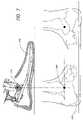
- FIG. 5is a side view of the lower limb prosthesis of FIG. 1 with the cover shown partially removed, wherein the ankle-motion-controlled foot is adjusted to accommodate an incline.
- FIG. 6is a side view of a lower limb prosthesis of FIG. 5 , wherein the ankle-motion-controlled foot is adjusted to accommodate a decline.
- FIG. 7is a schematic drawing indicating the correlation between an ankle pivot point on an exemplifying embodiment of a prosthetic foot unit with the natural ankle joint of a human foot.
- FIG. 8is a graph depicting the range of ankle motion of an exemplifying embodiment of a prosthetic or orthotic system during one full stride on a level surface.
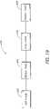
- FIG. 9is a block diagram of an exemplifying embodiment of a control system architecture of a prosthetic or orthotic system having an ankle-motion-controlled foot.
- FIG. 10is a table illustrating control signals usable to adjust the ankle angle of a prosthetic or orthotic system according to one embodiment of the invention.
- FIG. 11is a graph depicting an exemplifying embodiment of the relationship between the control of a prosthetic or orthotic system and the motion of a corresponding sound limb.
- FIG. 12Ais a perspective view of another embodiment of a lower limb prosthesis.
- FIG. 12Bis a side view of the lower limb prosthesis of FIG. 12A .
- FIG. 12Cis a cross-sectional view of the lower limb prosthesis of FIG. 12B along plane M-M.
- FIG. 13is a perspective view of one embodiment of an actuator which may be used with the lower limb prosthesis of FIG. 12A .
- FIG. 14is a side-view of the actuator of FIG. 13 .
- FIG. 15is a rear view of the actuator of FIG. 13 .
- FIG. 16is a top view of the actuator of FIG. 13 .
- FIG. 17is a cross-sectional side view of the actuator of FIG. 13 .
- FIG. 18is an exploded view of the actuator of FIG. 13 .
- FIG. 20is a disassembled view of a lower limb prosthesis having an ankle-motion-controlled foot unit according to another embodiment of the invention.
- FIG. 21is a disassembled view of a sensor assembly usable with the lower limb prosthesis of FIG. 20 .
- FIG. 22is a graph illustrating preferred ankle response angles for respective degrees of incline/decline.
- Some preferred embodiments of the invention described hereinrelate generally to prosthetic and orthotic systems and, in particular, to prosthetic and orthotic devices having an ankle-motion-controlled foot. While the description sets forth various embodiment-specific details, it will be appreciated that the description is illustrative only and should not be construed in any way as limiting the invention. Furthermore, various applications of the invention, and modifications thereto, which may occur to those who are skilled in the art, are also encompassed by the general concepts described herein.
- prostheticand “prosthesis” as used herein are broad terms and are used in their ordinary sense and refer to, without limitation, any system, device or apparatus usable as an artificial substitute or support for a body part.
- orthotic and “orthosis” as used hereinare broad terms and are used in their ordinary sense and refer to, without limitation, any system, device or apparatus usable to support, align, prevent, protect, correct deformities of, immobilize, or improve the function of parts of the body, such as joints and/or limbs.
- ankle deviceas used herein is a broad term and is used in its ordinary sense and relates to any prosthetic, orthotic or ankle-assisting device.
- transtibialas used herein is a broad term and is used in its ordinary sense and relates to without limitation any plane, direction, location, or cross-section that is located at or below a knee joint of a body, including artificial knee joints.
- transfemoralas used herein is a broad term and is used in its ordinary sense and relates to without limitation any plane, direction, location, or cross-section that is located at or above a knee joint of a body, including artificial knee joints.
- sagittalas used herein is a broad term and is used in its ordinary sense and relates to any description, location, or direction relating to, situated in, or being in or near the median plane (i.e., the plane divides the body lengthwise into right and left halves) of the body or any plane parallel or approximately parallel thereto.
- a “sagittal plane”may also refer to any vertical anterior to posterior plane that passes through the body parallel or approximately parallel to the median plane and that divides the body into equal or unequal right and left sections.
- coronalas used herein is a broad term and is used in its ordinary sense and relates to any description, location, or direction relating to, situated in, or being in or near the plane that passes through the long axis of the body.
- a “coronal plane”may also refer to any plane that passes vertically or approximately vertically through the body and is perpendicular or approximately perpendicular to the median plane and that divides the body into anterior and posterior sections.
- FIG. 1illustrates one embodiment of a lower limb prosthesis 100 having an ankle-motion-controlled foot with an attachment member.
- the prosthesis 100comprises an attachment member, in the form of a lower limb member 102 , operatively coupled to a foot unit 104 .
- attachment memberis a broad term and is used in its ordinary sense and in a prosthetic foot embodiment relates to, without limitation, any member that attaches either directly or indirectly to the foot unit 104 and is moveable in relation thereto, for example by a pivoting motion, and is used to attach the prosthesis 100 to a stump or intermediate prosthesis.
- the attachment membermay take the form of a lower limb member in an ankle-prosthesis embodiment.
- the attachment membermay be used to attach to and support a body part, such as with a brace, which also is moveably connected to a second member, such as a foot unit, which would also attach to and support a body part, such as the foot.
- the lower limb member 102is a generally elongated member with a main longitudinal axis that extends in approximately a tibial direction, that is, a direction that extends generally along the axis of a natural tibia bone.
- FIG. 1depicts the lower limb member 102 as being a generally vertical orientation.
- the lower limb member 102may comprise multiple sections.
- the lower limb member 102may comprise two elongated sections that extend approximately parallel in a tibial direction and that are connected together.
- the lower limb member 102comprises a two-sided chamber having two substantially symmetrical parts to form a partially enclosed housing.
- the lower limb member 102may comprise a hollow member, such as a tube-like structure.
- the lower limb member 102may comprise elongated flat portions or rounded portions.
- the structure of the lower limb member 102is not elongated.
- the lower limb member 102may comprise a generally circular, cylindrical, half-circular, dome-shaped, oval or rectangular structure.
- a possible lower limb memberis the ankle module and the structures described in U.S. patent application Ser. No. 10/742,455, filed Dec. 18, 2003, and entitled “PROSTHETIC FOOT WITH ROCKER MEMBER,” the entirety of which is hereby incorporated herein by reference and is to be considered as part of this specification.
- the lower limb member 102is generally formed of a machine metal, such as aluminum, or a carbon fiber material. In other embodiments of the invention, the lower limb member 102 may comprise other materials that are suitable for prosthetic devices. In one embodiment, the lower limb member 102 advantageously has a height between approximately 12 and 15 centimeters. In other embodiments of the invention, the lower limb member 102 may have a height less than 12 centimeters or height greater than 15 centimeters depending on the size of the user and/or the intended use of the prosthesis 100 . For example, the lower limb member 102 may have a height of approximately 20 centimeters.
- the prosthesis 100is configured such that the main longitudinal axis of the lower limb member 102 is substantially perpendicular to a lower surface of the foot unit 104 when the prosthesis 100 is in a resting position.
- the lower limb member 102may be substantially perpendicular to a level ground surface when the foot unit 104 rests on the ground. Such a configuration advantageously provides a user with increased support and/or stability.
- the lower limb member 102further comprises a cover 106 .
- the cover 106houses and/or protects the inner components of the lower limb member 102 .
- the cover 106may be rounded or may be shaped in the form of a natural human leg.
- the lower limb member 102further comprises an attachment portion 108 to facilitate coupling of the lower limb member 102 .
- the attachment portion 108 of the lower limb member 102couples the prosthesis 100 to a pylon 110 .
- the attachment portion 108may be configured to couple the prosthesis 100 to a stump of an amputee or to another prosthetic device.
- FIG. 1also depicts a control wire 112 usable to provide power to and/or communicate control signals to the prosthesis 100 .
- the foot unit 104may comprise various types of prosthetic or orthotic feet. As illustrated in FIG. 1 , the foot unit 104 incorporates a design described in Applicant's co-pending U.S. patent application Ser. No. 10/642,125, entitled “LOW PROFILE PROSTHETIC FOOT,” and filed Aug. 15, 2003 the entirety of which is hereby incorporated by reference and is to be considered as part of this specification.
- the foot unit 104may comprise a standard LP VARI-FLEX® unit available from ⁇ ssur.
- the foot unit 104is configured to exert a proportional response to weight or impact levels on the foot unit 104 .
- the foot unit 104may comprise shock absorption for comfortable loading of the heel and/or for returning expended energy.
- the foot unit 104may comprise a full-length toe lever with enhanced flexibility so as to provide a stride length for the prosthetic limb that mimics the stride length of the healthy limb.
- the foot unit 104may comprise a split-toe configuration, which facilitates movement on uneven terrain.
- the foot unit 104may also include a cosmesis or a foot cover such as, for example, a standard Flex-Foot cover available from ⁇ ssur.
- FIG. 2depicts the prosthesis 100 with the cover 106 removed.
- a lower end of the lower limb member 102is coupled to the foot unit 104 at a pivot assembly 114 .
- the lower limb member 102is coupled to an ankle plate of the foot unit 104 , which extends generally rearward and upward from a toe portion of the foot unit 104 .
- the pivot assembly 114allows for angular movement of the foot unit 104 with respect to the lower limb member 102 .
- the pivot assembly 114advantageously comprises at least one pivot pin.
- the pivot assembly 114comprises a hinge, a multi-axial configuration, a polycentric configuration, combinations of the same or the like.
- the pivot assembly 114is located on a portion of the foot unit 104 that is near a natural ankle location of the foot unit 104 .
- the pivot assembly 114may be bolted or otherwise releasably connected to the foot unit 104 .
- FIG. 2further depicts the prosthesis 100 having an actuator 116 .
- the actuator 116advantageously provides the prosthesis 100 with the necessary energy to execute angular displacements synchronized with the amputee's locomotion.
- the actuator 116may cause the foot unit 104 to move similar to a natural human foot.
- the lower end of the actuator 116is coupled to the foot unit 104 at a first attachment point 118 .
- the foot attachment point 118is advantageously located on the upper surface of the foot unit 104 on a posterior portion thereof.
- the upper end of the actuator 116is coupled to the lower limb member 102 at a second attachment point 120 .
- the linear motion (or extension and contraction) of the actuator 116controls, or actively adjusts, the angle between the foot unit 104 and the lower limb member 102 .
- FIG. 2depicts the actuator 116 comprising a double-screw motor, wherein the motor pushes or pulls a posterior portion of the foot unit 104 with respect to the lower limb member 102 .
- the actuator 116comprises other mechanisms capable of actively adjusting an angle, or providing for motion between, multiple members.
- the actuator 116may comprise a single-screw motor, a piston cylinder-type structure, a servomotor, a stepper motor, a rotary motor, a spring, a fluid actuator, or the like.
- the actuator 116may actively adjust in only one direction, the angle between the lower limb member 102 and the foot unit 104 .
- the weight of the usermay also be used in controlling the angle caused by and/or the movement of the actuator 116 .
- FIG. 2illustrates the actuator 116 in a posterior configuration, wherein the actuator 116 is located behind the lower limb member 102 .
- the actuator 116may be used in an anterior configuration, wherein the actuator 116 is located in front of the lower limb member 102 .
- the actuator 116comprises an auto adjusting ankle structure and incorporates a design, such as described in U.S. Pat. No. 5,957,981, the entirety of which is hereby incorporated by reference and is to be considered as a part of this specification.
- the particular configuration or structuremay be selected to most closely imitate the movement and location of a natural human ankle joint and to facilitate insertion of the prosthesis 100 into an outer cosmesis.
- the actuator 116is advantageously configured to operate so as to not to emit loud noises, such as intermittent noises, perceptible by the user and/or others.
- the actuator 116may also be configured to not operate or adjust if the prosthesis 100 experiences torque, such as in the sagittal plane, that exceeds a certain level. For example, if the torque level exceeds four Newton meters (Nm), the actuator 116 may cease to operate or may issue an alarm.
- NmNewton meters
- the actuator 116may also be substantially enclosed within the cover 106 as shown in FIG. 1 such that the portions of the actuator 116 are not visible and/or exposed to the environment. In another embodiment, the actuator may be at least partially enclosed by the lower limb member 102 .
- FIG. 2further depicts control circuitry 122 usable to control the operation of the actuator 116 and/or the foot unit 104 .
- the control circuitry 122comprises at least one printed circuit board (PCB).
- the PCBmay further comprise a microprocessor.
- Softwaremay also reside on the PCB so as to perform signal processing and/or control the movement of the prosthesis 100 .
- the prosthesis 100includes a battery (not shown) that powers the control circuitry 122 and/or the actuator 116 .
- the batterycomprises a rechargeable lithium ion battery that preferably has a power cycle of at least 12 to 16 hours. In yet other embodiments, the power cycle of the battery may be less than 12 hours or may be more than 16 hours.
- the batterycomprises a lithium polymer battery, fuel cell technology, or other types of batteries or technology usable to provide power to the prosthesis 100 .
- the batteryis removably attached to a rear surface of the lower limb member 102 , to other portions of the prosthesis 100 , or is located remote the prosthesis 100 .
- the prosthesis 100may be connected to an external power source, such as through a wall adapter or car adapter, to recharge the battery.
- the prosthesis 100is configured to lock in a neutral position, such as the lower limb member 102 being aligned generally vertical relative to a level ground surface when the foot unit 104 is resting on the level ground surface, when the battery is out of power or enters a low power stage. Such locking provides for operational safety, reliability, and/or stability for a user.
- the prosthesis 100may also provide a battery status display that alerts the user as to the status (i.e., charge) of the battery.
- the prosthesis 100locks into a substantially neutral position when the motion control functions of the prosthesis 100 are turned off or disabled by a user.
- a cosmesis material or other dressingsmay be used with the prosthesis 100 so as to give the prosthesis 100 a more natural look or shape.
- the cosmesis, dressings, or other filler materialmay be used to prevent contaminants, such as dirt or water, from contacting the components of the prosthesis 100 .
- FIG. 3depicts a side view of the prosthesis 100 according to one embodiment of the invention.
- the actuator 116further comprises a main housing 124 , a lower extendable portion 126 , and an upper extendable portion 128 .
- the lower extendable portion 126couples the main housing 124 of the actuator 116 to the foot unit 104 at the first attachment point 118 .
- the upper extendable portion 128couples the main housing 124 of the actuator 116 to the lower limb member 102 at the second attachment point 120 .
- the lower extendable portion 126 and/or the upper extendable portion 128move into and/or out of the main housing 124 of the actuator 116 to adjust an angle between the foot unit 104 and the lower limb member 102 .
- the actuator 116causes the lower extendable portion 126 and/or the upper extendable portion 128 to contract or withdraw into the main housing 124 .
- at least one of the extendable portions 126 , 128may have a threaded surface such that rotation in one direction (e.g., clockwise) causes the extendable portion to withdraw into the main housing 124 of the actuator.
- at least one of the extendable portions 126 , 128comprises multiple telescoping pieces such that, upon contraction, one of the multiple pieces of extendable portion contracts into another of the multiple pieces without withdrawing into the main housing 124 .
- the lower extendable portion 126 and/or the upper extendable portion 128may extend from the main housing 124 .
- extension of the lower extendable portion 126 and/or the upper extendable portion 128causes an increase in the angle between the lower limb member 102 and the foot unit 104 .
- a contraction of the lower extendable portion 126 and/or the upper extendable portion 128causes a decrease in the angle between the foot unit 104 and the lower limb member 102 .
- FIG. 4illustrates a rear view of the prosthesis 100 depicted in FIGS. 1-3 .
- the cover 106extends around the posterior portion of the prosthesis 100 to house at least a portion of the actuator 116 such that portions of the actuator 116 are not visible and/or not exposed to the environment.
- FIGS. 5 and 6illustrate one embodiment of the prosthesis 100 as it adjusts to inclines and declines.
- the prosthesis 100is depicted as adjusting to an incline.
- the actuator 116extends so as to decrease an angle ⁇ between the lower limb member 102 and the foot unit 104 (or “dorsiflexion”).
- ⁇an angle between the lower limb member 102 and the foot unit 104
- the angular range of motion of the prosthesis 100is from about 0 to 10 degrees from the neutral position. Other embodiments may also facilitate exaggerated dorsiflexion during swing phase.
- FIG. 6illustrates the prosthesis 100 as it adjusts to a decline.
- the actuator 116extends so as to increase the angle ⁇ between the lower limb member 102 and the foot unit 104 (or “plantarflexion”).
- plantarflexionin one embodiment, the angular range of motion of the prosthesis 100 is from about 0 to 20 degrees from the neutral position. Such plantarflexion mimics natural ankle movement and provides for greater stability to an amputee or a user.
- the total range of motion about the ankle pivot axis of the prosthesis 100is approximately 30 degrees or more.
- the motion-controlled foot of the prosthesis 100advantageously accommodates different terrain, operates while traveling up and down stairs, and facilitates level ground walking.
- the prosthesis 100may provide for automatic heel height adjustability. Heel height may be measured, in one embodiment, from an ankle portion of the lower limb member 102 to a ground surface when the foot unit 104 is generally flat to the ground. For example, a user may adjust to various heel heights, such as through pressing one or more buttons, such that the prosthesis 100 automatically aligns itself to the appropriate heel height.
- the prosthesis 100includes a plurality of predetermined heel heights. In yet other embodiments, the prosthesis 100 may automatically adjust the heel height without the need for user input.
- FIGS. 5 and 6further illustrate one embodiment of the attachment portion 108 .
- the attachment portion 108provides alignment between the natural limb of the amputee and the prosthesis 100 and may be configured so as to decrease pressure peaks and shear forces.
- the attachment portion 108may be configured to attach to another prosthesis, to the stump of the amputee, or to another component.
- the attachment portion 108comprises a socket connector.
- the socket connectormay be configured to receive a 32 mm-thread component, a male pyramid type coupler, or other components.
- the attachment portion 108may also comprise, or be configured to receive, a female pyramid adapter.
- FIG. 7further illustrates a schematic drawing indicating the correlation between an ankle pivot point on a prosthetic foot unit 204 with the natural human ankle joint of a foot.
- the prosthetic foot unit 204comprises a pivot assembly 214 that corresponds to an ankle joint 240 of a human foot 242 .
- the pivot assembly 114is located near the mechanical ankle center of rotation of the prosthesis 100 .
- FIG. 8illustrates a graph depicting the possible range of ankle motion of an embodiment of the prosthesis 100 during one full stride on a level surface.
- the x-axis of the graphrepresents various points during one full stride of a user (i.e., 0 to 100 percent).
- the y-axisrepresents the ankle angle ( ⁇ ) of the prosthesis 100 relative to the ankle angle when the prosthesis is in a neutral position.
- the ankle angle ( ⁇ )varies from approximately 20 degrees plantarflexion (i.e., neutral position angle+20 degrees) to approximately 10 degrees dorsiflexion (i.e., neutral position angle ⁇ 10 degrees).
- the prosthesis 100is configured to provide dampening or passive, soft resistance to changes in the angle between the lower limb member 102 and the foot unit 104 .
- An example of a system for controlling such dampeningis disclosed in U.S. Pat. No. 6,443,993, which is hereby incorporated herein by reference and is to be considered as a part of this specification.
- dampening of the prosthesis 100may be provided by hydraulic dampers.
- other components or devices that are known in the artmay be used to provide dampening for the prosthesis 100 .
- the dampersmay be dynamically controlled, such as through an electronic control system, which is discussed in more detail below.
- the dampersmay be controlled through mechanical and/or fluid-type structures.
- an orthotic systemmay comprise at least one actuator that actively controls the angle of an orthosis that is used with an injured or debilitated ankle.
- the orthotic systemmay, in addition to the electronic control of the orthotic system, provide for the user's control or natural movement of the injured ankle or leg.
- the above-described systemsmay be implemented in prosthetic or orthotic systems other than transtibial, or below-the-knee, systems.
- the prosthetic or orthotic systemmay be used in a transfemoral, or above-the-knee, system, such as is disclosed in U.S. Provisional Application No. 60/569,512, filed May 7, 2004, and entitled “MAGNETORHEOLOGICALLY ACTUATED PROSTHETIC KNEE;” U.S. Provisional Application No. 60/624,986, filed Nov. 3, 2004, and entitled “MAGNETORHEOLOGICALLY ACTUATED PROSTHETIC KNEE;” and U.S. patent application Ser. No.
- the prosthetic or orthotic systemmay include both a prosthetic or orthotic ankle and/or a prosthetic or orthotic knee.
- FIG. 9illustrates a block diagram of one embodiment of a system architecture of a control system 300 for an ankle-motion-controlled foot.
- the control system 300is usable by the lower limb prosthesis 100 depicted in FIGS. 1-6 .
- the control system 300is usable by an orthotic system or a rehabilitation system having an ankle-motion-controlled foot, or other motion-controlled limb.
- the control system 300is based on a distributed processing system wherein the different functions performed by the prosthetic or orthotic system, such as sensing, data processing, and actuation, are performed or controlled by multiple processors that communicate with each other.
- the control system 300includes a sensor module 302 , an ankle device 304 (such as, for example, the prosthesis 100 depicted in FIG. 1 ), a central processing unit (“CPU”) 305 , a memory 306 , an interface module 308 , a control drive module 310 , an actuator 316 and a power module 318 .
- a sensor module 302such as, for example, the prosthesis 100 depicted in FIG. 1
- a central processing unit (“CPU”) 305such as, for example, the prosthesis 100 depicted in FIG. 1
- CPUcentral processing unit
- the control system 300 depicted in FIG. 9processes data received from the sensing module 302 with the CPU 305 .
- the CPU 305communicates with the control drive module 310 to control the operation of the actuator 316 so as to mimic natural ankle movement by the ankle device 304 .
- the control system 300may predict how the ankle device 304 may need to be adjusted in order to accommodate movement by the user.
- the CPU 305may also receive commands from a user and/or other device through the interface module 308 .
- the power module 318provides power to the other components of the control system 300 . Each of these components is described in more detail below.
- the sensor module 302is used to measure variables relating to the ankle device 304 , such as the position and/or the movement of the ankle device 304 throughout a gait cycle.
- the sensor module 320is advantageously located on the ankle device 304 .
- the sensor module 302may be located near a mechanical ankle center of rotation of the ankle device 304 , such as the pivot assembly 114 of the prosthesis 100 depicted in FIG. 2 .
- the sensor module 302may be located on the user's natural limb that is attached to, or associated with, the ankle device 304 .
- the sensorsare used to capture information relating to the movement of the natural limb on the user's ankle-device side to adjust the ankle device 304 .
- the sensor module 302advantageously includes a printed circuit board housing, multiple sensors, such as accelerometers, which each measures an acceleration of the ankle device 304 in a different axis.
- the sensor module 302may comprise three accelerometers that measure acceleration of the ankle device 304 in three substantially, mutually perpendicular axes. Sensors of the type suitable for the sensor module 302 are available from, for example, Dynastream Innovations, Inc. (Alberta, Canada).
- the sensor module 302may include one or more other types of sensors in combination with, or in place of, accelerometers.
- the sensor module 302may include a gyroscope configured to measure the angular speed of body segments and/or the ankle device 304 .
- the sensor module 302includes a plantar pressure sensor configured to measure, for example, the vertical plantar pressure of a specific underfoot area.
- the sensor module 302may include one or more of the following: kinematic sensors, single-axis gyroscopes, single- or multi-axis accelerometers, load sensors, flex sensors or myoelectric sensors that may be configured to capture data from the user's natural limb.
- U.S. Pat. Nos. 5,955,667, 6,301,964, and 6,513,381also illustrate examples of sensors that may be used with embodiments of the invention, which patents are herein incorporated by reference in their entireties and are to be considered as part of this specification.
- the sensor module 302may be used to capture information relating to, for example, one or more of the following: the position of the ankle device 304 with respect to the ground; the inclination angle of the ankle device 304 ; the direction of gravity with respect to the position of the ankle device 304 ; information that relates to a stride of the user, such as when the ankle device 304 contacts the ground (e.g., “heel strike”), is in mid-stride, or leaves the ground (e.g., “toe-off”), the distance from the ground of the prosthesis 100 at the peak of the swing phase (i.e., the maximum height during the swing phase); the timing of the peak of the swing phase; and the like.
- a stride of the usersuch as when the ankle device 304 contacts the ground (e.g., “heel strike”), is in mid-stride, or leaves the ground (e.g., “toe-off”), the distance from the ground of the prosthesis 100 at the peak of the swing phase (i.
- the sensor module 302is configured to detect gait patterns and/or events. For example, the sensor module 302 may determine whether the user is in a standing/stopped position, is walking on level ground, is ascending and/or descending stairs or sloped surfaces, or the like. In other embodiments, the sensor module 302 is configured to detect or measure the heel height of the ankle device 304 and/or determine a static shank angle in order to detect when the user is in a sitting position.
- the sensor module 302is further configured to measure environmental or terrain variables including one or more of the following: the characteristics of the ground surface, the angle of the ground surface, the air temperature and wind resistance.
- the measured temperaturemay be used to calibrate the gain and/or bias of other sensors.
- the sensor module 302captures information about the movement and/or position of a user's natural limb, such as a healthy leg. In such an embodiment, it may be preferable that when operating on an incline or a decline, the first step of the user be taken with the healthy leg. Such would allow measurements taken from the natural movement of the healthy leg prior to adjusting the ankle device 304 .
- the control system 300detects the gait of the user and adjusts the ankle device 304 accordingly while the ankle device 304 is in a swing phase of the first step. In other embodiments of the invention, there may be a latency period in which the control system 300 requires one or two strides before being able to accurately determine the gait of the user and to adjust the ankle device 304 appropriately.
- the sensor module 302has a default sampling rate of 100 hertz (Hz). In other embodiments, the sampling rate may be higher or lower than 100 Hz or may be adjustable by a user, or may be adjusted automatically by software or parameter settings. In addition, the sensor module 302 may provide for synchronization between types of data being sensed or include time stamping. The sensors may also be configured so as to have an angular resolution of approximately 0.5 degrees, allowing for fine adjustments of the ankle device 304 .
- the sensor module 302is configured to power down into a “sleep” mode when sensing is not needed, such as for example, when the user is relaxing while in a sitting or reclining position. In such an embodiment, the sensor module 302 may awake from the sleep state upon movement of the sensor module 302 or upon input from the user. In one embodiment, the sensor module 302 consumes approximately 30 milliamps (mA) when in an “active” mode and approximately 0.1 mA when in a “sleep” mode.
- mAmilliamps
- FIG. 9illustrates the sensor module 302 communicating with the CPU 305 .
- the sensor module 302advantageously provides measurement data to the CPU 305 and/or to other components of the control system 300 .
- the sensor module 302is coupled to a transmitter, such as, for example, a Bluetooth® transmitter, that transmits the measurements to the CPU 305 .
- a transmittersuch as, for example, a Bluetooth® transmitter
- other types of transmitters or wireless technologymay be used, such as infrared, WiFi®, or radio frequency (RF) technology.
- RFradio frequency
- wired technologiesmay be used to communicate with the CPU 305 .
- the sensor module 302sends a data string to the CPU 305 that comprises various types of information.
- the data stringmay comprise 160 bits and include the following information:
- TSTimestamp
- AccXlinear acceleration of foot along X axis
- AccYlinear acceleration of foot along Y axis
- AccZlinear acceleration of foot along Z axis
- GyroXangular acceleration of foot along X axis
- GyroYangular acceleration of foot along Y axis
- GyroZangular acceleration of foot along Z axis
- DegXfoot inclination angle in coronal plane
- DegYfoot inclination angle in sagittal plane
- FSlogic state of switches in the ankle device 304
- Morientation of the sensors.
- other lengths of data stringscomprising more or less information may be used.
- the CPU 305advantageously processes data received from other components of the control system 300 .
- the CPU 305processes information relating to the gait of the user, such as information received from the sensor module 302 , determines locomotion type (i.e., gait pattern), and/or sends commands to the control drive module 310 .
- the data captured by the sensor module 302may be used to generate a waveform that portrays information relating to the gait or movement of the user. Subsequent changes to the waveform may be identified by the CPU 305 to predict future movement of the user and to adjust the ankle device 304 accordingly.
- the CPU 305may detect gait patterns from as slow as 20 steps per minute to as high as 125 steps per minute. In other embodiments of the invention, the CPU 305 may detect gait patterns that are slower than 20 steps per minute or higher than 125 steps per minute.
- the CPU 305processes data relating to state transitions according to the following table (TABLE 1).
- TABLE 1shows possible state transitions usable with the control system 300 .
- the first column of TABLE 1lists possible initial states of the ankle device 304 , and the first row lists possible second states of the ankle device 304 .
- the body of TABLE 1identifies the source of data used by the CPU 305 in controlling, or actively adjusting, the actuator 316 and the ankle device 304 during the transition from a first state to a second state; wherein “N” indicates that no additional data is needed for the state transition; “L” indicates that the CPU 305 uses transition logic to determine the adjustments to the ankle device 304 during the state transition; and “I” indicates the CPU receives data from an interface (e.g., interface module 308 , external user interface, electronic interface or the like).
- Transition logic usable with embodiments of the inventionmay be developed by one with ordinary skill in the relevant art. Examples of transition logic used in similar systems and methods to embodiments of the present invention are disclosed in U.S. Provisional Application No.
- the above described states in TABLE 1are predefined states of the ankle device 304 .
- the “OFF” statemay indicate that the functions of the ankle device 304 and the actuator 316 are in an off or suspend mode.
- the “HEEL_HEIGHT_CAL” staterelates to the measuring of a heel height from a static sensor angle such as, for example, when the ankle device 304 is not in motion.
- the “SENSOR_CAL” staterelates to surface angle calibration when the user is walking on a level surface.
- the “NEUTRAL” staterelates to when the ankle device 304 is locked in a substantially fixed position.
- the “WALK” staterelates to when the user is walking, such as on a level or sloped surface.
- the “STAIRS_UP” and “STAIRS_DOWN” statesrelate to when the user is walking, respectively, up and down stairs.
- the “RELAX” staterelates to when the user is in a relaxed position.
- the “RELAX” staterelates to when a user is in a sitting position with the limb having the ankle device 304 crossed over the other limb.
- the control system 300may cause the ankle device 304 to move into a maximum plantarflexion position to mimic, for example, the natural position and/or look of a healthy foot.
- the “PANTS” staterelates to when a user is putting on pants, trousers, shorts or the like. In such a state, the control system 300 may, in one embodiment, cause the ankle device 304 to move into a maximum plantarflexion position to facilitate putting the clothing on over the ankle device 304 .
- other statesare usable with the ankle device 304 in place of, or in combination with, the states identified in TABLE 1.
- statesmay be defined that correspond to lying down, cycling, climbing a ladder or the like.
- the CPU 305 and/or control system 300may process or derive data from sources other than those listed in TABLE 1.
- the CPU 305may perform a variety of other functions.
- the CPU 305may use information received from the sensor module 302 to detect stumbling by the user.
- the CPU 305may function as a manager of communication between the components of the control system 300 .
- the CPU 305may act as the master device for a communication bus between multiple components of the control system 300 .
- the CPU 305communicates with the power module 318 .
- the CPU 305may provide power distribution and/or conversion to the other components of the control system 300 and may also monitor battery power or battery life.
- the CPU 305may function so as to temporarily suspend or decrease power to the control system 300 when a user is in a sitting or a standing position.
- the CPU 305may also process error handling, such as when communication fails between components, an unrecognized signal or waveform is received from the sensor module 302 , or when the feedback from the control drive module 310 or the ankle device 304 causes an error or appears corrupt.
- the CPU 305uses or computes a security factor when analyzing information from the sensor module 302 and/or sending commands to the control drive module 310 .
- the security factormay include a range of values, wherein a higher value indicates a higher degree of certainty associated with a determined locomotion type of the user, and a lower security factor indicates a lower degree of certainty as to the locomotion type of the user.
- adjustmentsare not made to the ankle device 304 unless the locomotion type of the user is recognized with a security factor above a predetermined threshold value.
- the CPU 305includes modules that comprise logic embodied in hardware or firmware, or that comprise a collection of software instructions written in a programming language, such as, for example C++.
- a software modulemay be compiled and linked into an executable program, installed in a dynamic link library, or may be written in an interpretive language such as BASIC.
- software modulesmay be callable from other modules or from themselves, and/or may be invoked in response to detected events or interrupts.
- Software instructionsmay be embedded in firmware, such as an EPROM or EEPROM.
- hardware modulesmay be comprised of connected logic units, such as gates and flip-flops, and/or may be comprised of programmable units, such as programmable gate arrays or processors.
- FIG. 9further depicts CPU 305 including a memory 306 for storing instructions and/or data.
- the memory 306may store one or more of the following types of data or instructions: an error log for the other components of the control system 300 ; information regarding gait patterns or curves; information regarding past activity of the user (e.g., number of steps); control parameters and set points; information regarding software debugging or upgrading; preprogrammed algorithms for basic movements of the prosthetic or orthotic system; calibration values and parameters relating to the sensor module 302 or other components; instructions downloaded from an external device; combinations of the same or the like.
- the memory 306may comprise any buffer, computing device, or system capable of storing computer instructions and/or data for access by another computing device or a computer processor.
- the memory 306is a cache that is part of the CPU 305 .
- the memory 306is separate from the CPU 305 .
- the memory 306comprises random access memory (RAM) or may comprise other integrated and accessible memory devices, such as, for example, read-only memory (ROM), programmable ROM (PROM), and electrically erasable programmable ROM (EEPROM).
- the memory 306comprises a removable memory, such as a memory card, a removable drive, or the like.
- the CPU 305may also be configured to receive through the interface module 308 user- or activity-specific instructions from a user or from an external device.
- the CPU 305may also receive updates to already existing instructions.
- the CPU 305may communicate with a personal computer, a personal digital assistant, or the like so as to download or receive operating instructions.
- Activity-specific instructionsmay include, for example, data relating to cycling, driving, ascending or descending a ladder, adjustments from walking in snow or sand, or the like.
- the interface module 308comprises an interface that the user accesses so as to control or manage portions or functions of the prosthetic or orthotic system.
- the interface module 308is a flexible keypad having multiple buttons and/or multiple light emitting diodes (LEDs) usable to receive information from and/or convey information to a user.
- the LEDsmay indicate the status of a battery or may convey a confirmation signal to a user.
- the interface module 308may be advantageously located on the ankle device 304 .
- the interface module 308may comprise a USB connector usable for communication to an external computing device, such as a personal computer.
- the interface module 308comprises an on/off switch.
- the interface module 308may receive input regarding the user-controlled heel height or a forced relaxed mode of the prosthetic or orthotic system.
- the usermay adjust the type of response desired of the prosthesis or enable/disable particular functions of the ankle device 304 .
- the input from the usermay be entered directly via the interface module 308 , such as through actuating a button, or user input may be received via a remote control.
- the interface module 308may comprise a touch screen, buttons, switches, a vibrator, an alarm, or other input-receiving or output structures or devices that allow a user to send instructions to or receive information from the control system 300 .
- the interface module 308comprises an additional structure, such as a plug, for charging a battery powering the control system 300 , such as at home or in a vehicle.
- the interface module 308may also communicate directly or indirectly with components of the control system 300 other than the CPU 305 .
- the control drive module 310is used to translate high-level plans or instructions received from the CPU 305 into low-level control signals to be sent to the actuator 316 .
- the control drive module 310comprises a printed circuit board that implements control algorithms and tasks related to the management of the actuator 316 .
- the control drive module 310may be used to implement a hardware abstraction layer that translates the decision processes of the CPU 305 to the actual hardware definition of the actuator 316 .
- the control drive module 310may be used to provide feedback to the CPU 305 regarding the position or movement of the actuator 316 or ankle device 304 .
- the control drive module 310may also be used to adjust the actuator 316 to a new “neutral” setting upon detection by the CPU 305 that the user is traveling on an angled surface.
- control drive module 310is located within the ankle device 304 . In other embodiments, the control drive module 310 may be located on the outside of the ankle device 304 , such as on a socket, or remote to the ankle device 304 .
- the actuator 316provides for the controlled movement of the ankle device 304 .
- the actuator 316functions similarly to the actuator 116 described with respect to FIGS. 1-6 , which actuator 116 controls the ankle motion of the prosthesis 100 .
- the actuator 316may be configured to control the motion of an orthotic device, such as a brace or other type of support structure.
- the ankle device 304comprises any structural device that is used to mimic the motion of a joint, such as an ankle, and that is controlled, at least in part, by the actuator 316 .
- the ankle device 304may comprise a prosthetic device or an orthotic device.
- the power module 318includes one or more sources and/or connectors usable to power the control system 300 .
- the power module 318is advantageously portable, and may include, for example, a rechargeable battery, as discussed previously.
- the power module 318communicates with the control drive module 310 and the CPU 305 .
- the power module 318communicates with other control system 300 components instead of, or in combination with, the control drive module 310 and the CPU 305 .
- the power module 318communicates directly with the sensor module 302 .
- the power module 318may communicate with the interface module 308 such that a user is capable of directly controlling the power supplied to one or more components of the control system 300 .
- FIG. 9depicts two types of links: primary communication links, which are depicted as solid lines between the components, and secondary communication links, which are depicted as dashed lines.
- primary communication linksoperate on an established protocol.
- the primary communication linksmay run between physical components of the control system 300 .
- Secondary communication linksmay operate on a different protocol or level than the primary communication links. For example, if a conflict exists between a primary communication link and a secondary communication link, the data from the primary communication link will override the data from the secondary communication link.
- the secondary communication linksare shown in FIG. 9 as being communication channels between the control system 300 and the environment.
- the modulesmay communicate with each other and/or the environment through other types of communication links or methods. For example, all communication links may operate with the same protocol or on the same level of hierarchy.
- the components of the control system 300may be integrated in different forms.
- the componentscan be separated into several subcomponents or can be separated into more devices that reside at different locations and that communicate with each other, such as through a wired or wireless network.
- the modulesmay communicate through RS232 or serial peripheral interface (SPI) channels. Multiple components may also be combined into a single component. It is also contemplated that the components described herein may be integrated into a fewer number of modules. One module may also be separated into multiple modules.
- control system 300may include more or fewer components than described above.
- the control system 300may further include an actuator potentiometer usable to control, or fine-tune, the position of the actuator 316 .
- the usermay also use the actuator potentiometer to adjust the heel height of the ankle device 304 .
- the actuator potentiometercommunicates with the CPU 305 .
- the control system 300may include a vibrator, a DC jack, fuses, combinations of the same, or the like.
- FIG. 10is a table that depicts possible control signals that may be involved in adjusting the ankle angle of a prosthetic or orthotic device when a user is transitioning between different states, or types of locomotion, according to one embodiment of the invention.
- the states listed in a column 402identify a first state of the user
- the states listed in a row 404identify a second state of the user, or the state to which the user is transitioning.
- the remainder of the tableidentifies possible actions that may be taken by the prosthetic or orthotic device with respect to the ankle angle.
- “User set point”is the neutral, or default, value that may be set during shoe heel height adjustment.
- the angles specifiedare examples of changes to the ankle angle of the prosthetic or orthotic device.
- the ankle anglemay be adjusted to the angle of the stairs, such as for example, ⁇ 10 degrees (or 10 degrees dorsiflexion).
- Ankle angles given in the “Incline (up)” and “Decline” columnsreflect threshold levels of ankle angle adjustment depending on the angle of the incline.
- the following tableillustrates possible ankle motion strategies for one embodiment of the invention.
- the first column of TABLE 2lists different types of locomotion types or gait patterns that may be frequently detected.
- the second column of TABLE 2identifies examples of ankle angle adjustment of the prosthetic or orthotic device during the swing phase of each of the identified locomotion types.
- Ankle adjusts to dorsiflexione.g., 7.5°
- Descending StairsAnkle adjusts to dorsiflexion (e.g., 5°)
- Inclineup
- x°2.5°
- y5°.
- FIG. 11depicts a graph that illustrates the interaction and relationship between the control of a prosthetic or orthotic leg and the measurements taken from a healthy, sound leg.
- FIG. 11depicts the movement of a prosthetic or orthotic leg and a healthy leg during one full stride of a user.
- the graphshows the prosthetic or orthotic leg as being in a “stance” position or being planted on a surface, such as the ground.
- the ankle angle of the prosthetic or orthotic legmay decrease (dorsiflexion).
- the ankle angle of the prosthetic or orthotic legmay then increase (plantarflexion) to facilitate natural stride movements.
- the ankle angle of the prosthetic or orthotic legis not actively adjusted during the stance phase.
- the healthy legmay be in a swinging position, wherein the healthy leg is not in contact with the ground. Between the points of approximately 40% and 60%, both legs are in contact with the ground.
- the prosthetic or orthotic legis in a swinging position, and the healthy leg is in contact with the ground.
- the graph in FIG. 11shows that the ankle angle of the prosthetic or orthotic leg is adjusted during the swing phase. This angle adjustment may be based on previous measurements of the healthy leg during the swing phase of the healthy leg. In one embodiment, during the beginning portion of the swing phase of the prosthetic or orthotic leg, the ankle angle of the prosthetic or orthotic leg may decrease. This allows, for example, a toe portion of the prosthetic or orthotic leg to clear stairs. Toward the latter portion of the swing phase of the prosthetic or orthotic leg, the ankle angle of the prosthetic or orthotic leg may then increase before contacting the ground. In other embodiments, the angle adjustment is based on readings taken by sensors on the prosthetic side.
- FIG. 11is illustrative of the functioning of one embodiment of the invention under certain conditions. Other embodiments or circumstances may require a longer or shorter stance or swing phase and require other adjustments to the angle of the ankle portion of the prosthetic leg.
- FIGS. 12A-12Cillustrate another embodiment of a lower limb prosthesis 100 ′ configured to be attached to a human limb.
- the lower limb prosthesis 100 ′is similar to the lower limb prosthesis 100 illustrated in FIG. 2 , except as noted below.
- the reference numerals used to designate the various components of the lower limb prosthesis 100 ′are identical to those used for identifying the corresponding components of the lower limb prosthesis 100 in FIG. 2 , except that a “′” has been added to the reference numerals.
- the lower limb prosthesis 100 ′comprises a first portion 102 ′ coupled to a second portion 104 ′, wherein the portions 102 ′, 104 ′ are moveable relative to each other to mimic a natural human joint.
- the first portionis a lower limb member 102 ′ and the second portion is a prosthetic foot unit 104 ′ operatively coupled to the lower limb member 102 ′ to mimic a natural human ankle joint.
- the foot unit 104 ′includes a heel portion 104 a ′ at a rear end of the foot unit 104 ′ and a toe portion 104 b ′ at a front end of the foot unit 104 ′.
- the heel and toe portions 104 a ′, 104 b ′can be unitary. In another embodiment, the heel and toe portions 104 a ′, 104 b ′ can be separate components fastened to each other via, for example, bolts, screws, adhesives and the like.
- the prosthetic foot unit 104 ′is an LP VARI-FLEX® prosthetic foot commercially available from ⁇ ssur. However, the foot unit 104 ′ can have other configurations or designs.
- the first and second portionscan be an upper leg member and a lower leg member, respectively, which are coupled to mimic a natural human knee joint.
- the lower limb prosthesis 100 ′may also comprise a frame 106 ′ extending between the foot unit 104 ′ and the lower limb member 102 ′.
- an attachment portion 108 ′ of the lower limb member 102 ′facilitates the coupling of the lower limb member 102 ′ to another member, such as, for example, the pylon 110 depicted in FIGS. 1-4 .
- the attachment portion 108 ′is a pyramid.
- the lower limb member 102 ′, or support membercouples to the foot unit 104 ′ at its lower end via a pivot assembly 114 ′, which is attached to the prosthetic foot unit 104 ′.
- the pivot assembly 114 ′is attached at about the rear 1 ⁇ 3 of the foot unit 104 ′.
- the pivot assembly 114 ′can be attached at other locations on the foot unit 104 ′.
- the pivot assembly 114 ′mimics a natural human ankle joint.
- a cover 106 b ′is disposed about an actuator 500 of the lower limb prosthesis 100 ′ to substantially protect the actuator 500 and inhibit the intrusion of foreign matter.
- the lower limb prosthesis 100 ′may also include a control wire, such as the control wire 112 depicted in FIGS. 1-4 , to provide power to and/or communicates control signals to the prosthesis 100 ′.
- the actuator 500provides the prosthesis 100 ′ with the necessary energy to execute angular displacements synchronized with an amputee's locomotion.
- the actuator 500couples the first and second portions 102 ′, 104 ′ of the prosthesis 100 ′ together, which in the illustrated embodiment correspond to the lower limb member 102 ′ and the prosthetic foot unit 104 ′.
- the actuatoris configured to adjust an angle between the lower limb member 102 ′ and the foot unit 104 ′.
- the actuator 500couples to the foot unit 104 ′ and the lower limb member 102 ′ at first and second attachment points 118 ′, 120 ′, respectively.
- the prosthesiscan include control circuitry to control the operation of the actuator 500 , such as, for example, the control circuitry 122 depicted in FIGS. 2 and 3 .
- FIGS. 13-18illustrate one embodiment of an actuator 500 that may be used with the lower limb prosthesis 100 ′ discussed above.
- the actuator 500preferably comprises a stator or top unit 510 having an attachment end 512 and a bottom end 514 .
- the attachment end 512is a C-shaped clamp (see FIG. 15 ) having a first opening 512 a and a second opening 512 b aligned along a first axis X 1 that extends generally perpendicular to a longitudinal axis Y of the actuator 500 .
- the attachment end 512can have other suitable configurations.
- the openings 512 a , 512 bare preferably sized to receive a fastener therethrough, such as a bolt, screw, or pin (not shown), to allow the top unit 510 to be fastened to, for example, the upper end of the lower limb member 102 ′ at the second attachment point 120 ′.
- a fastenersuch as a bolt, screw, or pin (not shown)
- the bottom end 514 of the top unit 510preferably has a circumferential wall 514 a and a bottom surface 516 .
- the bottom surface 516curves from the circumferential wall 514 a toward a center of the bottom surface 516 .
- the bottom surface 516preferably includes a recess portion 518 located generally at the center of the bottom surface 516 .
- the recess portion 518 on the bottom surface 516 of the top unit 510is preferably sized to receive a ball bearing 522 therein, as further discussed below.
- the circumferential wall 514 aincludes a protrusion 520 that extends outward from the wall 514 a .
- the protrusion 520extends substantially along the entire circumference of the wall 514 a .
- the protrusion 520can be a plurality of protrusions positioned at discrete locations about the circumference of the wall 514 a.
- the actuator 500also comprises a first elongate member or rotor 530 with a body extending from a top end 530 a to a bottom end 530 b along a length 532 , and having a diameter 534 .
- the length 532is between about 25 mm and about 70 mm.
- the diameter 534is between about 12 mm and about 40 mm. More preferably, the diameter 534 is about 17 mm.
- the rotor 530has a circumferential flange 536 at the top end 530 a , the flange 536 having a diameter greater than the diameter 534 of the body.
- the top end 530 ahas an outer surface 537 that curves generally upward from the circumferential flange toward a center 537 a of the surface 537 .
- the surface 537defines a recessed portion 538 generally disposed at the center 537 a thereof.
- the recessed portion 538is preferably contoured to receive the ball bearing 522 therein, such that the ball bearing 522 couples the top unit 510 to the rotor 530 .
- the top unit 510 and the rotor 530couple to each other solely via the ball bearing 522 .
- the ball bearing 522is a single ball bearing. However, other suitable bearings can be used.
- a thrust bearingis disposed between the top unit 510 and the rotor 530 .
- the rotor 530is preferably an elongate nut defining a hollow central portion 539 , which defines a wall 539 a with threads 540 disposed along at least a portion the length of the wall 539 a.
- the ball bearing 522preferably couples the top unit 510 to the first elongate member 530 .
- the curvature of the surface 537 of the rotor 530 and the curvature of the bottom surface 516 of the top unit 510define a gap 541 therebetween.
- the gap 541extends preferably circumferentially about the center 537 a of the surface 537 .
- at least one magnet 542is disposed in the gap 541 and attached to the surface 537 via, for example, an adhesive.
- a plurality of magnets 542are disposed about the center 537 a of the surface 537 .
- an annular magnet(not shown) can be disposed on the surface 537 , with the annulus of the magnet aligned with the center 537 a .
- the magnets 542are preferably configured to exert a magnetic force on the top unit 510 and the rotor 530 , so that the force draws the top unit 510 and the rotor 530 toward each other.
- the actuator 500also includes a retainer 550 having a height 551 and a wall 552 defining an inner diameter 554 .
- the retainer 550includes a flange 556 having an inner portion 556 a extending radially inward from the wall 552 and an outer portion 556 b extending radially outward from the wall 522 , wherein the inner and outer portions 556 a , 556 b are preferably disposed at a bottom end of the wall 552 .
- the illustrated embodimentshows the flange 556 as being continuous around the circumference of the retainer 550
- the flange 556can instead be a plurality of flange members disposed at discrete locations about the circumference of the retainer 556 .
- the inner diameter 554 of the retainer 550is sized to receive the rotor 530 and the top unit 510 therein.
- the inner diameter 554 of the retainer 550is preferably at least slightly greater than the diameter of the flange 536 of the rotor 530 , so that the flange 536 of the rotor 530 does not engage the wall 552 of the retainer 550 .
- the inner diameter 554 of the retainer 550is preferably at least slightly greater than the diameter of at least a portion of the circumferential wall 514 a of the top unit 510 .
- the protrusions 520 on the circumferential wall 514 a of the top unit 510preferably engage a portion of the wall 552 of the retainer 550 , such that the top unit 510 and the retainer 550 are coupled to each other.
- rotor 530rotates about, and translates along, the longitudinal axis Y, as further discussed below.
- the rotor 530remains coupled to the top unit 510 via the ball bearing 522 , but selectively moves in and out of contact with the retainer 550 via the inner flange 556 a , as further described below.
- the rotor 530moves between contact with the top unit 510 , via the ball bearing 522 , and contact with the retainer 550 via the inner flange 556 a.
- a first magnet 560 a and a second magnet 560 bare disposed about a portion of the rotor 530 .
- the first and second magnets 560 a , 560 bpreferably have a height 562 a , 562 b and an inner diameter 564 a , 564 b larger than the diameter 534 of the rotor 530 , so that the magnets 560 a , 560 b fit about the rotor 530 .
- the inner diameters 564 a , 564 b of the first and second magnets 560 a , 560 bare between about 12 mm and about 40 mm, and more preferably about 17 mm.
- the magnets 560 a , 560 bare magnetized rings with 24 poles. Additionally, as shown in FIG. 17-18 , a spacer 568 is disposed between the first and second magnets 560 a , 560 b . Preferably, the spacer 568 also has a diameter greater than the diameter 534 of the rotor 530 , so that the spacer 568 fits about the rotor 530 . Though the illustrated embodiment depicts two magnets 560 a , 560 b and one spacer 568 , one of ordinary skill in the art will recognize that any number of magnets and spacers can be used.
- the actuator 500also comprises a sleeve 570 with a cylindrical body 571 having a length 572 and a diameter 574 such that the sleeve 570 fits about the rotor 530 .
- the length 572is between about 10 mm and about 70 mm, and more preferably about 20 mm.
- the diameter 574is preferably between about 12 mm and about 40 mm, and more preferably about 17 mm.
- the sleeve 570has an inner diameter greater than the diameter 534 of the first elongate member 530 , and has an outer diameter that is smaller than the inner diameter of the first and second magnets 560 a , 560 b and the spacer 568 .
- the first and second magnets 560 a , 560 b and the spacer 568fit about the sleeve 570 , which in turn fits about the rotor 530 .
- the rotor 530 , sleeve 570 , magnets 560 a , 560 bare disposed substantially adjacent each other.
- the sleeve 570also has a lip 576 that extends circumferentially about the sleeve 570 .
- the lip 576extends continuously around the sleeve 570 at a radial distance away from a surface of the sleeve 570 substantially equal to a thickness of at least one of the first and second magnets 560 a , 560 b .
- the lip 576is preferably positioned a distance away from a top end of the sleeve 570 so as to support the first and second magnets 560 a , 560 b and the spacer 568 about the sleeve 570 so that the first and second magnets 560 a , 560 b and the spacer 568 do not extend past the top end of the sleeve 570 .
- the actuator 500also comprises a motor 580 .
- the motor 580has a height 582 and an inner surface 586 with an inner diameter 584 , such that the motor 580 can be disposed about the rotor 530 .
- the motorhas a length of between about 10 mm and about 60 mm, and more preferably about 25 mm.
- the inner diameter 584 of the motor 580is preferably between about 15 mm and about 50 mm. In a preferred embodiment, the diameter 584 of the motor 580 is about 22 mm. As illustrated in FIG.
- the motor 580extends about the rotor 530 , such that the sleeve 570 , the first and second magnets 560 a , 560 b and the spacer 568 are disposed between the rotor 530 and the inner diameter 584 of the motor 580 .
- the motor 580preferably comprises windings configured to rotate the rotor 530 via the magnets 560 a , 560 b .
- the motor 580is a stepper motor.
- the motor 580can be a DC motor, a piezo-electric motor, a DC brushless motor, and a servo motor.
- the actuatoralso comprises an o-ring 590 and a roller bearing 600 disposed between the motor 580 and a cover portion 610 having a protruding portion 612 .
- the cover 610preferably houses the motor 580 therein when the actuator 500 is fully assembled.
- a bellows 620is preferably disposed adjacent a bottom end of the cover 610 . The bellows 620 advantageously inhibits the entry of foreign particles, such as dust and water, into contact with the motor 580 and a second elongate member 630 of the actuator 500 .
- the second elongate member 630extends along a length 632 and has a diameter 634 .
- the second elongate member 630is a screw with threads 636 along a portion of the length 632 .
- the screw 630has an attachment portion 638 at a bottom end thereof with an opening 638 a that extends therethrough along an axis X 2 generally orthogonal to the longitudinal axis Y of the actuator 500 .
- the opening 638 ais preferably sized to receive a fastener therethrough, such as a bolt, a screw or a pin. Accordingly, the attachment portion 638 can be fastened to, for example, the prosthetic foot unit 104 ′ at the first attachment point 118 ′.
- the threads 636 of the screw 630are adapted to threadingly engage the threads 540 on the nut 530 .
- the threads 636 , 540 on the screw 630 and the nut 530 , respectivelyare designed to be on the boundary of a self-locking coupling.
- the threads 636 , 540 of the nut 530 and the screw 630are trapezoidal threads.
- the threads 636 , 540can be ACME centralized threads with a working diameter of about 14 mm, a pitch of about 2 mm, and about two leads. However, any suitable thread type can be used.
- the threads 636 , 540are made of Aluminum Bronze and Stainless Steel. However, other suitable metals and alloys can be used.
- the threads 540 in the nut 530are cut, while the threads 636 in the screw 630 and ground and coated with a coating, such as a permanent oil coating.
- the thread lengths in the nut 530are configured to provide minimum friction during operation of the actuator 500 , while delivering optimum support and strength to the actuator 500 .
- the threads 540 , 636 of the nut 530 and the screw 630can have other configurations and be made of other materials to provide a desired performance characteristic.
- the material and coating of the threads, as well as the pitch, working diameter, and number of leadscan be varied to provide a different interface friction between the threads 636 , 540 .
- the pitch and configuration of the threads 636 , 530can be chosen so that a load applied (e.g., along the longitudinal axis Y) to the screw 630 and/or nut 530 assembly will not initiate a self-generated movement of the actuator 500 . That is, the pitch and configuration of the threads 636 , 530 generate a friction force therebetween that is large enough to inhibit the relative rotation of the nut 530 and the screw 630 .
- the pitch and configuration of the threads 636 , 530can be chosen so that a load applied to the screw 630 and/or nut 530 along the longitudinal axis Y will initiate a self-generated movement of the actuator 500 .
- the screw 630preferably has a hollow portion 640 extending along a portion of the length 632 .
- the hollow portion 640reduces the weight of the screw 630 , thereby reducing the weight of the actuator 500 as a whole.
- an adoption ring 650is disposed about the screw 630 , wherein the ring 650 couples with the bottom end of the bellows 620 .
- the actuator 500has a compact assembly. As discussed above, the motor 580 is disposed about the rotor 530 , which is disposed about the elongate member or screw 630 . Accordingly, the actuator 500 takes up less space and can have a lower height than other designs. In one preferred embodiment, the actuator 500 has a height of between about 40 mm to about 70 mm in a collapsed configuration, and a height of between about 65 mm to about 130 mm in a fully extended configuration. Additionally, the hollow portion 640 of the screw 630 advantageously reduces the weight of the actuator 500 .
- the actuator 500advantageously minimizes friction between the stator or top unit 510 and the rotor or nut 530 .
- the ball bearing 522 disposed between the top unit 510 and the nut 530inhibits the generation of a friction force between the top unit 510 and the nut 530 , thereby allowing the nut 530 to rotate generally freely relative to the top unit 510 .
- the magnets 542draw the nut 530 toward the top unit 510 , as discussed above. Such a magnetic force lifts the nut 530 from engagement with the inner flange 556 a of the retainer 550 , thereby inhibiting the generation of friction between the retainer 550 and the nut 530 , as further discussed below.
- the magnetic forceis strong enough to lift the rotor 530 from engagement with the inner flange 556 a of the retainer in one desired phase of a gait cycle.
- the magnetic force of the magnets 542is strong enough to lift the rotor 530 from engagement with the inner flange 556 a of the retainer 550 in more than one desired phase of a gait cycle.
- the actuator 500can also advantageously be selectively locked during a desired phase of a gait cycle.
- the flange 536 of the rotor or nut 530can engage the inner flange 556 a of the retainer 550 , generating a friction force between the rotor 530 and the retainer 550 to inhibit the rotation of the rotor 530 .
- the friction force that is generatedis effectively a locking force that locks the actuator 500 .
- the flanges 536 , 556 aengage when the actuator 500 is in tension.
- the interaction of the threads 636 , 540 of the screw 630 and the nut 530can also generate a friction force to inhibit the rotation of the screw 630 and the nut 530 relative to each other.
- the interaction of the threads 636 , 540also generates a locking force that contributes to the locking of the actuator 500 .
- FIG. 19illustrates a flow chart showing the different phases of a gait cycle 670 of the lower limb prosthesis 100 ′ illustrated in FIGS. 12A-12C .
- the actuator 500is initially in a state of compression, wherein the flange 536 on the rotor 530 is displaced relative to the inner flange 556 a on the retainer 550 .
- the state of compression in the first phasearises from the operating relationship between the lower limb member 102 ′ and the prosthetic foot unit 104 ′.
- a loadis applied on the heel portion 104 a ′ of the foot unit 104 ′ (e.g., due to the weight or locomotion force of the user).
- Said loadapplies an upward force on the heel portion 104 a ′ of the foot unit 104 ′, causing the toe portion 104 b ′ to move away from the lower limb member 102 ′ by rotating about the main pivot axis of the pivot assembly 114 ′, which in turn applies a compression force on the second elongate member 630 via the first attachment point 118 ′.
- the compression forceis transferred from the second elongate member 630 onto the rotor 530 , so that the flange 536 of the rotor 530 moves away from the inner flange 556 a of the retainer 550 .
- the actuator 500is not actuated during the first phase 672 .
- the pitch of the threads 540 , 636 between the rotor 530 and the second elongated member 630advantageously generate an interface friction force between the threads 540 , 636 .
- the lower limb prosthesis 100 ′transitions into a second phase 674 where the foot unit 104 ′ is in a stance phase.
- the actuator 500transitions from a state of compression to a state of tension, so that a friction force is generated between the flange 536 of the rotor 530 and the inner flange 556 a of the retainer 550 , as discussed above.
- the state of tension in the stance phaseis generated by the movement of the lower limb member 102 ′ relative to the prosthetic foot member 104 ′ as the prosthesis 100 ′ transitions into the second phase 674 .
- the locomotion of the usere.g., due to forward movement
- Said loadcauses a rear portion of the foot unit 104 ′ to move downward, away from the lower limb member 102 ′, which in turn applies a tension force on the second elongate member 630 via the first attachment point 118 ′.
- the tension forceis transferred from the second elongate member 630 onto the rotor 530 , so that the flange 536 of the rotor 530 moves toward, and into engagement with, the inner flange 556 a of the retainer 550 .
- said engagement between the flange 536 of the rotor 530 and the inner flange 556 a of the retainer 550generates a friction force to inhibit the rotation of the rotor 530 .
- the friction forceis high enough to act as a brake to prevent the rotation of the rotor 530 .
- the actuator 500is not actuated during the second phase 674 .
- a third phase 676the foot unit 104 ′ transitions from a stance phase to a toe-off phase.
- the toe portion 104 b ′continues to be under load, as in the second phase. Accordingly, the actuator remains substantially in a state of tension, so that the rotor 530 is inhibited from rotating, as discussed above.
- the load on the toe portion 104 b ′is greater in the third phase than in the second phase of the gait cycle.
- the actuator 500is not actuated during the third phase 676 .
- a fourth phase 678the prosthetic foot unit 104 ′ is in a swing phase between toe-off and heel-strike, wherein the foot 104 ′ is not in contact with a support surface.
- the actuator 500is in a compression position. As discussed above, while in compression the flange 536 on the rotor 530 is separated from the inner flange 556 a of the retainer 550 , thereby allowing the rotor 530 to rotate generally freely relative to the retainer 550 .
- the state of compression during the swing phasearises from the operating relationship between the lower limb member 102 ′ and the prosthetic foot unit 104 ′.
- a loadis applied to the prosthetic foot unit 104 ′ due to the configuration of the foot unit 104 ′ (e.g., the weight of the foot unit 104 ′), which pulls the toe portion 104 b ′ downward, away from the lower limb member 102 ′.
- the downward force on the toe portion 104 b ′in turn applies a compression force on the second elongate member 630 via the first attachment point 118 ′.
- the compression forceis transferred from the second elongate member 630 onto the rotor 530 , so that the flange 536 of the rotor 530 moves away from the inner flange 556 a of the retainer 550 .
- the rotor 530is thus able to rotate generally freely relative to the retainer 550 .
- the movement of the flange 536 of the rotor 530 away from the inner flange 556 a of the retainer 550is facilitated by the magnets 542 , which draw the rotor 530 toward the top unit or stator 510 and away from the retainer 550 , thus inhibiting the generation of friction during the swing phase.
- the actuator 500is actuated during the swing phase to adjust the angle between the lower limb member 102 ′ and the prosthetic foot unit 104 ′.
- the ball bearing 522 disposed between the stator 510 and the rotor 530also inhibit the generation of friction between the rotor 530 and the retainer 550 . Therefore, the actuator 500 is actuated while under a light load, which advantageously reduces the wear and tear on the actuator 500 , providing for an extended operating life.
- the actuator 500inhibits the rotation of the rotor 530 relative to the second elongate member 630 when in a state of tension.
- the actuator 500can be operated to inhibit the rotation of the rotor 530 relative to the second elongate member 630 while in compression.
- the actuator 500can also be arranged so as to allow for the rotation of the rotor 530 relative to the second elongate member 630 when in a tension position.
- the magnets 542can generate a magnetic force sufficient to draw the rotor 530 away from the inner flange 556 a of the retainer 550 while the actuator 500 is in a state of tension.
- the actuator 500is actuated during the swing phase 678 of a gait cycle. However, one of ordinary skill in the art will recognize that the actuator 500 can be actuated during more than one phase of a gait cycle.
- the actuator 500can also be used with an orthotic device to adjust the angle of a first portion and a second portion of the orthotic device. Additionally, the actuator 500 , as described in the embodiments above, can advantageously be used to selectively lock the orthotic device during a desired phase of locomotion, as well as to minimize friction between the rotor 530 and the retainer 550 during the actuation of the actuator 500 to facilitate the operation of the orthotic device.
- a lower limb prosthesis or orthosisincludes at least one sensing device coupled thereto and that is substantially isolated from negative external effects or loads.
- the sensing deviceis capable of measuring angular movement of a prosthetic foot in a single direction while disregarding or filtering out movement and/or loads of the prosthetic foot in other directions.
- FIG. 20illustrates a disassembled view of a lower limb prosthesis 700 having an ankle-motion-controlled foot unit.
- certain componentssuch as certain bolts, washers, bearing plugs and the like, are not shown and described with reference to the illustrated prosthesis 700 .
- a skilled artisanwould recognize however, from FIG. 20 and the disclosure herein which components, or equivalents thereof, may be used with the depicted components of the illustrated prosthesis 700 .
- the prosthesis 700includes at least one sensor assembly that advantageously detects rotation of the foot unit about a single axis and substantially neglects axial and radial movement of the foot unit with respect to the axis.
- a sensor assemblymay be coupled to and or located near an axis of rotation of the prosthesis 700 .
- the illustrated lower limb prosthesis 700comprises a foot member 702 connectable by screws 703 to a heel member 704 .
- the foot member 702 and heel member 704may comprise a foot unit, such as an LP VARI-FLEX® prosthetic foot commercially available from ⁇ ssur.
- the foot member 702 and/or heel member 704may take on other configurations, or the lower limb prosthesis 700 may operate without a heel member 704 .
- the foot member 702is configured to rotatably attach to a main frame 706 , or attachment member, about a main pivot pin 708 extending through a base part 710 .
- the main pivot pin 708 and the base part 710form a pivot assembly that is configured to substantially mimic the natural motion of a healthy human ankle.
- the main pivot pin 708may allow for dorsiflexion and plantarflexion of the foot member 702 , as is described in more detail previously with respect to the prosthesis 100 of FIGS. 1-6 .
- the prosthesis 700further includes an actuator 712 operatively coupled to the foot member 702 through the base part 710 .
- the actuator 712couples to a lower pin 714 that allows for rotation of a bottom portion of the actuator 712 with respect to the base part 710 secured to a top, rear portion of the foot member 702 .
- the actuator 712is advantageously capable of adjusting at least one angle between the main frame 706 and the foot member 702 , such that the foot member 702 rotates about the main pivot pin 708 of the pivot assembly.
- the actuator 712comprises any one of the various types of actuators disclosed herein and is capable of actively adjusting the angle between the main frame 706 and the foot member 702 based on one or more signals received from an electronic control system.
- the lower limb prosthesis 700optionally further includes a keypad 716 to receive user input and a rear cover 718 that partially covers the actuator 712 .
- the prosthesis 700may also include other devices and/or couplings to facilitate attachment of the prosthesis 700 to a limb, such as a stump, of an amputee.
- the illustrated lower limb prosthesis 700further includes a sensor assembly 720 configured to couple to and extend through the base part 710 of the pivot assembly.
- the sensor assembly 720is configured to measure movement of at least one portion of the prosthesis 700 in at least one direction.
- the sensor assembly 720is configured and positioned to measure movement of a portion of the prosthesis 700 in a single direction.
- the sensor assembly 720is positioned within the main pivot pin 708 and extends along an axis (e.g., a pivot axis) substantially perpendicular to a longitudinal, or vertical, axis of the main frame 706 .
- the illustrated sensor assembly 720is capable of detecting, or measuring, rotation of the foot member 702 about the axis of the main pivot pin 708 .
- the sensor assembly 720is secured to the pivot assembly of the prosthesis 700 such that the sensor measurements are not affected by loads or forces in directions other than rotation about the main pivot pin 708 .
- axial or radial movements with respect to the axis of the main pivot pin 708do not affect the measurements of the sensor assembly 720 .
- FIG. 21illustrates a disassembled view showing further details of the components of the sensor assembly 720 of FIG. 20 .
- the sensor assembly 720includes a displacement measurement sensor 722 coupled to an elongated bellow portion 724 through an extender portion 726 .
- relative rotation of the foot member 702 with respect to the main frame 706is measured by the displacement measurement sensor 722 .
- the main pivot pin 708is rigidly attached to the base part 710 , and the elongated bellow portion 724 is positioned at least partially within the main pivot pin 708 .
- relative movement of the foot member 702 (and attached base part 710 ) with respect to the main frame 706causes relative rotation between the elongated bellow portion 724 (and attached extender portion 726 ) with respect to the displacement measurement sensor 722 .
- rotation of the foot member 702may cause rotation of the elongated bellow portion 724 with respect to the displacement measurement sensor 722 , which may be fixed with respect to the main frame 706 .
- rotation of the foot member 702may cause rotation of the displacement measurement sensor 722 with respect to the elongated bellow portion 722 , which may be fixed with respect to the main frame 706 .
- the displacement measurement sensor 722comprises a potentiometer, such as, for example, a linear or logarithmic potentiometer.
- rotation of the elongated bellow portion 724causes a corresponding rotation of the extender portion 726 and a rotatable input 727 of the potentiometer.
- other types of displacement measurement sensorsmay be used, such as, for example, rotational position transducers, optical or mechanical encoders, combinations of the same or the like, to measure movement and/or rotation of a component of the prosthesis 700 .
- the elongated bellow portion 724further includes a plurality of ridges 728 around an outside surface of the bellow portion 724 .
- the ridges 728advantageously eliminate or substantially reduce the effects of axial (e.g., along the axis of the bellow portion 724 ) and/or radial (e.g., a direction perpendicular to the axis of the bellow portion 724 ) movements and/or loads on measurements by the displacement measurement sensor 722 .
- at least some of the ridges 728may be located within a component housing at least a portion of the elongated bellow portion 724 .
- such a componentmay include the main pivot pin 708 depicted in FIG. 20 .
- the ridges 728may advantageously isolate movement of the elongated bellow portion 724 to rotation about the axis of the elongated bellow portion 724 and the main pivot pin 708 .
- the elongated bellow portion 724may include a plurality of grooves or other surface features that isolate movement of the elongated bellow portion 724 to a single direction.
- the sensor assembly 720may function without the extender portion 726 or the ridges 728 .
- the sensor assembly 720may include a flexible compression membrane that couples the displacement measurement sensor 722 to the main pivot pin 708 and that absorbs unwanted movement (e.g., axial and/or radial movement).
- the sensor assembly 720has been described with reference to particular embodiments, other configurations for the sensor assembly 702 may be used with the prosthesis 700 .
- the main pivot pin 708may be rigidly attached to the main frame 706 .
- either the displacement sensor 722 or the elongated bellow portion 724may also be affixed to the main frame 706 such that relative movement of the foot member 702 with respect to the main frame 706 is detected by the displacement measurement sensor 722 .
- the prosthesis 700may include other types of sensor assemblies usable to detect movement of at least one component of the prosthesis 700 .
- the prosthesis 700may comprise a ball joint assembly that has its movement constrained in at least one direction by geometric constraints surrounding the ball joint, which constraints may include, for example, one or more pins or flat surfaces that engage one or more surfaces of the ball joint.
- the sensor assembly 720may include a flexible material that is stiff against twisting forces but allows for longitudinal compression and/or radial movement.
- the sensor assembly and/or prosthesis 700may advantageously used with a variety of motion-controlled prosthetic and/or orthotic devices, examples of which are described in more detail herein and in U.S. patent application Ser. No. 11/056,344, filed on Feb. 11, 2005, and entitled “SYSTEM AND METHOD FOR MOTION-CONTROLLED FOOT UNIT,” which is hereby incorporated by reference herein in its entirety and is to be considered a part of this specification.
- the ankle device 304there are certain defined states of the ankle device 304 .
- One of these statesis the “RELAX” state.
- the control device 300may initiate the “RELAX” state.
- the sensor module 302detects when the user has moved to a relaxed position, such as sitting, crossing legs, reclining, lying down, crawling, leaning, etc.
- the sensor module 302may detect these relaxed positions by measuring combinations of vertical acceleration (from which it may determined, for example, whether the overall ankle device 304 , particularly the foot unit 104 (with reference to FIG. 1 ), is in a tilted position with respect to the ground, such as resting on the heel with legs outstretched in a sitting or lying down position), horizontal/lateral acceleration, and time.
- the sensor module 302may comprise an accelerometer capable of measuring acceleration in the y-axis.
- the measured vertical accelerationcorresponds to the force of gravity.
- the accelerometermay be placed on the ankle device 304 .
- the accelerometermay be placed on the lower limb member 102 (with reference to FIG. 1 ), though the accelerometer may be placed anywhere on the ankle device 304 .
- the accelerometermay be used to measure an angle of the lower limb member 102 relative to vertical, which may then be used to determine an angle of the overall ankle device relative to the ground.
- the accelerometermay measure the standard force of gravity, 9.8 m/s 2 .
- the accelerometermay measure a fraction of the Earth's global force of gravity relative to the changing angle of the ankle device 304 with respect to the ground.
- a sensor module 302configured to measure acceleration in the vertical plane may be used to determine the stationary angle of the ankle device 304 with respect to the ground.
- the sensor module 302may indicate that the ankle device 304 is tilted at an angle of 90° with respect to the ground. This might indicate, for example, that the user is lying completely flat on the back.
- the sensor module 302may indicate that the ankle device 304 is at an angle of 45° with respect to the ground, indicating perhaps that the user is sitting down with legs outstretched in such a manner as to form a 45° angle with respect to the ground.
- the sensor module 302may also comprise an accelerometer configured to measure acceleration in the horizontal, or lateral, plane. This accelerometer may measure the ground acceleration of the ankle device 304 as the user moves in horizontal directions.
- the control device 300may also comprise a timer (not shown) that may be used to measure the amount of time during which the sensor module 302 detects certain conditions of acceleration.
- the control device 300may be configured to monitor the measurements of acceleration by the sensor module 302 over a period of time.
- a range of angles of the ankle device 304 compared to the groundis defined that indicates the movement of the user to a relaxed position.
- the control device 300may determine that the angle between the ankle device 304 and the ground, as detected by the sensor module 302 , is within the defined range.
- a range of lateral/horizontal acceleration of the ankle device 304may be defined.
- the control device 300may determine that the lateral/horizontal acceleration of the ankle device 304 , as detected by the sensor module 302 , falls within the defined range.
- a range of timemay be defined during which the above-mentioned conditions may be met.
- the control device 300may determine that the ankle device, for a specified period of time, is at angle with respect to ground within the defined range and/or is accelerating within the defined range indicative of a user's movement to a relaxed position.
- an algorithm that triggers execution of the “RELAX” statemight define the variables: start maximum acceleration delta (the upper limit of possible acceleration of the ankle device 304 that triggers the “RELAX” state), the start minimum angle (the lower limit of the angle of the ankle device 304 with respect to ground that triggers the “RELAX” state), the start maximum angle (the upper limit of the angle of the ankle device 304 with respect to ground that triggers the “RELAX” state), and start time (the amount of time that a combination of the other variables may be satisfied to trigger the “RELAX” state).
- the start maximum acceleration deltamay be about 1 m/s 2 , indicating a threshold such that movement artifacts from the user should be less than about 1 m/s 2 .
- the maximum acceleration deltamay be between about 0.1 m/s 2 and 50 m/s 2 .
- the start minimum angle of the foot member relative to the groundmay be about 30 degrees, and the start maximum angle may be ⁇ 90 degrees, for example, representing that a user is lying down on the stomach.
- the range of anglesmay be between about ⁇ 90° and +90°, the latter representing, for example, that a user is lying down on the back.
- the start timemay for example be about 1 second or more.
- the control device 300may detect conditions indicative of a user's movement out of a relaxed position and may initiate an “EXIT” state.
- the determination of a user's movement out of a relaxed positionmay be similar to the determination of a user's movement into a relaxed position.
- an algorithm that triggers execution of the “EXIT” statemight define the variables: end minimum acceleration delta (the lower limit of possible acceleration of the ankle device 304 that triggers the “EXIT” state), the end minimum angle (the lower limit of the angle of the ankle device 304 with respect to ground that triggers the “EXIT” state), and the end maximum angle (the upper limit of the angle of the ankle device 304 with respect to ground that triggers the “EXIT” state).
- the “EXIT” statemay be initiated regardless of whether the “RELAX” state is initiated first.
- the “EXIT” statemay adjust the device for a preferred configuration for exiting a relaxed position, even if the relaxed position is never detected and/or the “RELAX” state is never initiated.
- the control device 300may detect that the user is in a sitting position without causing the device to adjust to a particular “RELAX” state. It may be advantageous, however, to adjust the device to an “EXIT” state even though a “RELAX” state is not initiated.
- the “EXIT” statemay cause the device to be adjusted to a particular configuration that is advantageous when a user stands up from a sitting position, such as causing the device to dorsiflex in order to help shift the user's center of momentum to be over his/her feet to facilitate standing.
- This “EXIT” statemay be advantageous regardless of whether the device ever initiated a corresponding “RELAX” state.
- the end minimum acceleration deltamay be about 25 M/s 2 , allowing the user to exit the “RELAX” state by moving the ankle device greater than about 25 M/s 2 , such as by kicking the ankle device to the ground.
- the end minimum acceleration deltamay be between about 0.1 m/s 2 and 50 m/s 2 .
- the “EXIT” statemay also be defined by an angle of the ankle device relative to the ground being between an end minimum angle of about ⁇ 80 degrees and an end maximum angle of 10 degrees. Alternatively, the range of angles may be between about ⁇ 90° and 90°.
- the “RELAX” statespecifies a particular angle between the foot unit 104 and lower limb member 102 to which the ankle device 304 should be adjusted.
- the control drive module 310may cause the actuator 316 to adjust the ankle device 304 , for example, to a plantarflexion position of at least 10°, more preferably about 15°.
- a plantarflexion position of about 15°is when the lower limb prosthesis 100 is adjusted such that the angle between the foot unit 104 and the lower limb member 102 is about 15° more than the angle between the foot unit 104 and the lower limb member 102 in the neutral position.
- the “neutral position”is when the lower limb member 102 is vertical relative to a horizontal plane, such as the ground. This neutral position will translate to any range of actual ankle angle depending on the heel height of the foot unit 104 .)
- the plantarflexion of the ankle device 304may mimic the natural plantarflexion of a human foot, may be functionally advantageous, may be aesthetically appealing, etc.
- the control drive module 310may cause the actuator 316 to adjust the ankle device 304 , for example, to a dorsiflexion position of at least 5°.
- the range of anglesmay be between about 1° and 15° of dorsiflexion, and as discussed above, may be used either when the ankle is exiting from a “RELAX” state, a neutral position where there is 0° of plantarflexion and dorsiflexion, or any other desired configuration.
- a dorsiflexion position of 10°is when the lower limb prosthesis 100 is adjusted such that the angle between the foot unit 104 and the lower limb member 102 is 10° less than the angle between the foot unit 104 and the lower limb member 102 in the neutral position.
- the “RELAX” statemay specify a certain power mode, such as a low power mode, to which the control device 300 should automatically adjust.
- the control device 300might instruct the power module 318 to enter a low power mode, such as a hibernation mode, when the control device 300 determines to initiate the “RELAX” state.
- the “EXIT” statemay specify another power mode, such as a normal power mode, to which the control device 300 should automatically adjust.
- the “RELAX” state and the “EXIT” statemay specify certain heel heights, to which the control device should automatically adjust.
- some embodiments of the inventionmay define certain optimal adjustments for particular terrain variables. For instance, in some embodiments, there are optimal adjustments made while the user is ascending an incline or descending a decline. Thus, embodiments of the invention may define optimal adjustments for responding to changes in inclination and declination, such as adjusting the angle of the ankle device with respect to the ground.
- FIGS. 5 and 6illustrate embodiments of the invention engaging an inclining slope and declining slope, respectively.
- angle alpha ( ⁇ )indicates the relative slope of the incline.
- angle alpha ( ⁇ )indicates the relative slope of the decline.
- the angle theta ( ⁇ )indicates the angle between the lower limb member 102 and the foot unit 104 of a lower limb prosthesis 100 having an ankle-motion-controlled foot.
- the angle theta ( ⁇ )may be described as the neutral angle, or the angle of the lower limb prosthesis 100 on level ground.
- the lower limb prosthesis 100adjusts itself to engage the ground by contracting, for inclines, and by expanding, for declines, the angle theta ( ⁇ ) between the lower limb member 102 and the foot unit 104 .
- the lower limb prosthesis 100has been adjusted such that the angle theta ( ⁇ ) between the lower limb member 102 and the foot unit 104 increases or decreases a desired amount based on the angle alpha ( ⁇ ), which is the measurement of the relative slope.
- the angle theta ( ⁇ )reflects the neutral angle, measured when the lower limb prosthesis is on level ground, minus the degree of inclination, reflected by the angle alpha ( ⁇ ).
- the angle theta ( ⁇ ) in FIG. 6reflects the neutral angle plus the degree of declination.
- the angle of the foot unit 104 to the lower limb member 102may decrease by about 0 to 30 degrees when adjusting to an incline, or may increase by about 0 to 30 degrees when adjusting to a decline.
- the angle between the lower limb member 102 and the foot unit 104is said to be the neutral angle, or the angle of the device in the neutral position.
- the devicemay adjust the changing relative position of the foot unit 104 to the lower limb member 102 during the user's gait according to a response angle based on the detected degree of incline and/or decline.
- the devicedefines an adjusted neutral angle relative to the incline and/or decline.
- the angle between the lower limb member 102 and the foot unit 104may be defined as the adjusted neutral angle for the device with respect to the degree of incline and/or decline.
- Subsequent adjustments to the ankle angle between the lower limb member 102 and the foot unit 104may be made relative to this adjusted neutral angle.
- the adjustmentmay occur only during the swing phase, such that during stance, the angle of the ankle between the lower limb member 102 and the foot unit 104 remains substantially constant at the adjusted neutral angle.
- the adjustment relative to the adjusted neutral anglemay occur during both swing and stance phases. As the user leaves the stance phase and the device moves through the air without contact to the ground, the device may be adjusted as described above relative to the adjusted neutral angle (such as described by FIGS. 8 and 11 ). In other embodiments, the adjustments may also occur during the stance phase, when the foot unit 104 at least partially engages the ground.
- the foot unit 104may be adjusted relative to the lower limb member 102 so as to dorsiflex at the heel strike and midstance phase and then at toe off may be adjusted to a plantarflexion angle to provide natural push off.
- the foot unit 104may be adjusted relative to the lower limb member 102 so as to plantarfex at the heel strike phase and then during late stance and toe off may be adjusted to a dorsiflexion angle to aid roll over. It will be appreciated that these adjustments made during stance may also be utilized when walking on level ground. It will be further appreciated that the adjustments described above for inclined surfaces may be used for declined surfaces, and vice versa.
- the sensor module 302may be configured to determine if the user is walking up an incline or down a decline. This may be accomplished via dynamic analysis that traces the path of the ankle device 304 in the vertical plane.
- two acceleration sensorswith two axes measure the relative position of the ankle device to ground (gravity) during the stance phase.
- these sensorsare located on the lower limb member 102 (with respect to FIG. 1 ).
- the sensorsmay be located in the soles of shoes, in foot covers, on braces, etc. By measuring the gait from heel strike to toe off and how the foot is lifted in swing, the relative angle of incline and decline may be measured.
- the measurements of accelerationmay be used to determine the surface angle. Sensors capable of determining the surface angle are available from Dynastream Innovations, Inc. (Alberta, Canada). In some embodiments, the surface angle may be filtered by averaging a number of measurements, such as five measurements.
- the surface angle(or the filtered surface angle) may be applied to a formula that yields an ankle response angle.
- the ankle response angleis the optimal angle by which the lower limb prosthesis 100 (with respect to FIG. 1 ) should be adjusted for the specified surface angle, thereby configuring the lower limb prosthesis 100 to an adjusted neutral angle.
- the ankle response anglemay be measured with respect to level surface ground.
- the response angleis 10°
- lower limb prosthesis 100should be adjusted such that the toe end of the foot member 104 is rotated 10° toward the lower limb member 102 , making a 10° angle between the foot member 104 and the ground, assuming that the lower limb member 102 remains fixed with respect to level ground.
- the foot unit 104 of the lower limb prosthesis 100would completely engage the ground, as illustrated in FIG. 5 , for example. If, on the other hand, the response angle is ⁇ 10°, then lower limb prosthesis 100 should be adjusted such that the toe end of the foot member 104 is rotated 10° away from the lower limb member 102 , making a ⁇ 10° angle between the foot member and the ground, assuming that the lower limb member 102 remains fixed with respect to level ground. If the lower limb prosthesis 100 were adjusted ⁇ 10° in response to the detection of a decline of 10°, then the foot unit 104 of the lower limb prosthesis 100 would completely engage the ground, as illustrated in FIG. 6 , for example.
- the optimal ratio between the surface angle and the response angle for inclined slopesis 1:1.
- Other embodimentsmay result in the response angle for declined slopes being between about 10% and 100% of the measured surface angle, more preferably between about 10% and 50%.
- FIG. 22illustrates an x-y graph depicting above-defined ratios between surface angles and ankle response angles for inclines and declines, respectively.
- the optimal response angle for declining surfacesis a fraction of the angle of decline. This result is intuitively understood. As a user walks down a decline, the momentum created by the pull of gravity causes the user to roll through the gait pattern, resulting in less need for the foot unit 104 to automatically rotate downward to engage the ground. While walking up inclines, however, it is desirable for the foot unit 104 to automatically engage the ground without forcing the user to roll over the unbent lower limb prosthesis 100 .
Landscapes
- Health & Medical Sciences (AREA)
- Transplantation (AREA)
- Heart & Thoracic Surgery (AREA)
- Oral & Maxillofacial Surgery (AREA)
- Engineering & Computer Science (AREA)
- Biomedical Technology (AREA)
- Cardiology (AREA)
- Vascular Medicine (AREA)
- Life Sciences & Earth Sciences (AREA)
- Animal Behavior & Ethology (AREA)
- General Health & Medical Sciences (AREA)
- Public Health (AREA)
- Veterinary Medicine (AREA)
- Orthopedic Medicine & Surgery (AREA)
- Prostheses (AREA)
Abstract
Description
| TABLE 1 | |||||||||
| TRANSITIONS | |||||||||
| FROM STATE | HEEL— | ||||||||
| TO STATE | OFF | HEIGHT_CAL | SENSOR_CAL | NEUTRAL | WALK | STAIRS_UP | STAIRS_DOWN | RELAX | PANTS |
| OFF | N | I | I | I | N | N | N | I | I |
| HEEL_HEIGHT_CAL | L | N | N | L | N | N | N | N | N |
| SENSOR_CAL | L | N | N | L | N | N | N | N | N |
| NEUTRAL | I | I | I | N | L | L | L | L | I |
| WALK | I | N | N | L | N | L | L | N | N |
| STAIRS_UP | I | N | N | L | L | N | L | N | N |
| STAIRS_DOWN | I | N | N | L | L | L | N | N | N |
| RELAX | I | N | N | L | N | N | N | N | I |
| PANTS | I | N | N | I | N | N | N | N | N |
| TABLE 2 | |
| Locomotion | |
| Type/Gait Pattern | Ankle Motion During Swing Phase of Ankle Device |
| Level Ground | Toe clearance during swing |
| Walking | |
| Ascending Stairs | Ankle adjusts to dorsiflexion (e.g., 7.5°) |
| Descending Stairs | Ankle adjusts to dorsiflexion (e.g., 5°) |
| Incline (up) | Ankle adjust to dorsiflexion: |
| a) | Two incline angle threshold levels (x°, y°) | |
| b) | Stepwise (2 steps) angle adjustment (z°, w°) | |
| Example: If incline angle > x°, ankle will | ||
| adjust to −z°; if incline angle > y°, ankle | ||
| will adjust to −w°, wherein x = 2.5° and | ||
| y = 5°. |
| Decline | Ankle adjusts to plantarflexion: |
| a) | Two decline angle threshold levels (x°, y°) | |
| b) | Stepwise (2 steps) angle adjustment (z°, w°) | |
| Example: If decline angle > x°, ankle will | ||
| adjust to z°; if decline angle > y°, ankle will | ||
| adjust to w°, wherein x = 2.5° and y = 5°. |
| Sitting/Relaxed | Set Heel Height |
| Adjust Heel | Stepless heel height adjustment up to 20° |
| Height | plantarflexion |
Claims (24)
Priority Applications (8)
| Application Number | Priority Date | Filing Date | Title |
|---|---|---|---|
| US11/367,048US7637959B2 (en) | 2004-02-12 | 2006-03-01 | Systems and methods for adjusting the angle of a prosthetic ankle based on a measured surface angle |
| US11/367,049US7896927B2 (en) | 2004-02-12 | 2006-03-01 | Systems and methods for actuating a prosthetic ankle based on a relaxed position |
| EP07752020.3AEP1996129B1 (en) | 2006-03-01 | 2007-03-01 | Method for operating a prosthetic ankle |
| PCT/US2007/005292WO2007103136A2 (en) | 2006-03-01 | 2007-03-01 | Systems and methods for actuating a prosthetic ankle based on a relaxed position or measured surface angle |
| CN2007800158776ACN101437470B (en) | 2006-03-01 | 2007-03-01 | Systems and methods for actuating a prosthetic ankle based on a relaxed position or measured surface angle |
| CA2644222ACA2644222C (en) | 2006-03-01 | 2007-03-01 | Systems and methods for actuating a prosthetic ankle based on a relaxed position or measured surface angle |
| US13/037,147US9271851B2 (en) | 2004-02-12 | 2011-02-28 | Systems and methods for actuating a prosthetic ankle |
| US13/162,032US8657886B2 (en) | 2004-02-12 | 2011-06-16 | Systems and methods for actuating a prosthetic ankle |
Applications Claiming Priority (6)
| Application Number | Priority Date | Filing Date | Title |
|---|---|---|---|
| US54425904P | 2004-02-12 | 2004-02-12 | |
| US58823204P | 2004-07-15 | 2004-07-15 | |
| US11/057,391US7431737B2 (en) | 2004-02-12 | 2005-02-11 | System and method for motion-controlled foot unit |
| US11/056,344US7811334B2 (en) | 2004-02-12 | 2005-02-11 | System and method for motion-controlled foot unit |
| US11/367,048US7637959B2 (en) | 2004-02-12 | 2006-03-01 | Systems and methods for adjusting the angle of a prosthetic ankle based on a measured surface angle |
| US11/367,049US7896927B2 (en) | 2004-02-12 | 2006-03-01 | Systems and methods for actuating a prosthetic ankle based on a relaxed position |
Related Parent Applications (2)
| Application Number | Title | Priority Date | Filing Date |
|---|---|---|---|
| US11/056,344Continuation-In-PartUS7811334B2 (en) | 2004-02-12 | 2005-02-11 | System and method for motion-controlled foot unit |
| US11/057,391Continuation-In-PartUS7431737B2 (en) | 2004-02-12 | 2005-02-11 | System and method for motion-controlled foot unit |
Publications (2)
| Publication Number | Publication Date |
|---|---|
| US20060224246A1 US20060224246A1 (en) | 2006-10-05 |
| US7637959B2true US7637959B2 (en) | 2009-12-29 |
Family
ID=38370825
Family Applications (4)
| Application Number | Title | Priority Date | Filing Date |
|---|---|---|---|
| US11/367,048Active2025-11-24US7637959B2 (en) | 2004-02-12 | 2006-03-01 | Systems and methods for adjusting the angle of a prosthetic ankle based on a measured surface angle |
| US11/367,049Active2028-10-31US7896927B2 (en) | 2004-02-12 | 2006-03-01 | Systems and methods for actuating a prosthetic ankle based on a relaxed position |
| US13/037,147Expired - LifetimeUS9271851B2 (en) | 2004-02-12 | 2011-02-28 | Systems and methods for actuating a prosthetic ankle |
| US13/162,032Expired - LifetimeUS8657886B2 (en) | 2004-02-12 | 2011-06-16 | Systems and methods for actuating a prosthetic ankle |
Family Applications After (3)
| Application Number | Title | Priority Date | Filing Date |
|---|---|---|---|
| US11/367,049Active2028-10-31US7896927B2 (en) | 2004-02-12 | 2006-03-01 | Systems and methods for actuating a prosthetic ankle based on a relaxed position |
| US13/037,147Expired - LifetimeUS9271851B2 (en) | 2004-02-12 | 2011-02-28 | Systems and methods for actuating a prosthetic ankle |
| US13/162,032Expired - LifetimeUS8657886B2 (en) | 2004-02-12 | 2011-06-16 | Systems and methods for actuating a prosthetic ankle |
Country Status (5)
| Country | Link |
|---|---|
| US (4) | US7637959B2 (en) |
| EP (1) | EP1996129B1 (en) |
| CN (1) | CN101437470B (en) |
| CA (1) | CA2644222C (en) |
| WO (1) | WO2007103136A2 (en) |
Cited By (60)
| Publication number | Priority date | Publication date | Assignee | Title |
|---|---|---|---|---|
| US20100160844A1 (en)* | 2007-01-05 | 2010-06-24 | Benoit Gilbert | High Torque Active Mechanism for Orthotic and/or Prosthetic Devices |
| US20100286796A1 (en)* | 2009-05-05 | 2010-11-11 | Ossur Hf | Control systems and methods for prosthetic or orthotic devices |
| US20100305716A1 (en)* | 2007-11-07 | 2010-12-02 | Otto Bock Healthcare Gmbh | Method for controlling an orthopedic joint |
| US20100324698A1 (en)* | 2009-06-17 | 2010-12-23 | Ossur Hf | Feedback control systems and methods for prosthetic or orthotic devices |
| US7896927B2 (en)* | 2004-02-12 | 2011-03-01 | össur hf. | Systems and methods for actuating a prosthetic ankle based on a relaxed position |
| US8048007B2 (en) | 2005-02-02 | 2011-11-01 | össur hf | Prosthetic and orthotic systems usable for rehabilitation |
| WO2011163367A1 (en)* | 2010-06-22 | 2011-12-29 | Mcgregor Stephen J | Method of monitoring human body movement |
| US8231687B2 (en) | 2002-08-22 | 2012-07-31 | Victhom Human Bionics, Inc. | Actuated leg prosthesis for above-knee amputees |
| US8287477B1 (en) | 2003-09-25 | 2012-10-16 | Massachusetts Institute Of Technology | Active ankle foot orthosis |
| US8323354B2 (en) | 2003-11-18 | 2012-12-04 | Victhom Human Bionics Inc. | Instrumented prosthetic foot |
| US8419804B2 (en) | 2008-09-04 | 2013-04-16 | Iwalk, Inc. | Hybrid terrain-adaptive lower-extremity systems |
| US8435309B2 (en) | 2007-01-05 | 2013-05-07 | Victhom Human Bionics | Joint actuation mechanism for a prosthetic and/or orthotic device having a compliant transmission |
| US8480760B2 (en) | 2010-04-12 | 2013-07-09 | Northwestern University | Passive ankle-foot prosthesis and orthosis capable of automatic adaptation to sloped walking surfaces and method of use |
| US8500823B2 (en) | 2005-03-31 | 2013-08-06 | Massachusetts Institute Of Technology | Powered artificial knee with agonist-antagonist actuation |
| US8512415B2 (en) | 2005-03-31 | 2013-08-20 | Massachusetts Institute Of Technology | Powered ankle-foot prothesis |
| US8551184B1 (en) | 2002-07-15 | 2013-10-08 | Iwalk, Inc. | Variable mechanical-impedance artificial legs |
| US8617254B2 (en) | 2004-03-10 | 2013-12-31 | Ossur Hf | Control system and method for a prosthetic knee |
| US8696764B2 (en) | 2011-01-20 | 2014-04-15 | Northwestern University | Further improvements to ankle-foot prosthesis and orthosis capable of automatic adaptation to sloped walking surfaces |
| US8702811B2 (en) | 2005-09-01 | 2014-04-22 | össur hf | System and method for determining terrain transitions |
| US8709097B2 (en) | 2005-09-01 | 2014-04-29 | össur hf | Actuator assembly for prosthetic or orthotic joint |
| US8734528B2 (en) | 2005-03-31 | 2014-05-27 | Massachusetts Institute Of Technology | Artificial ankle-foot system with spring, variable-damping, and series-elastic actuator components |
| US8801802B2 (en) | 2005-02-16 | 2014-08-12 | össur hf | System and method for data communication with a mechatronic device |
| US8814949B2 (en) | 2005-04-19 | 2014-08-26 | össur hf | Combined active and passive leg prosthesis system and a method for performing a movement with such a system |
| US8864846B2 (en) | 2005-03-31 | 2014-10-21 | Massachusetts Institute Of Technology | Model-based neuromechanical controller for a robotic leg |
| US8870967B2 (en) | 2005-03-31 | 2014-10-28 | Massachusetts Institute Of Technology | Artificial joints using agonist-antagonist actuators |
| US8915968B2 (en) | 2010-09-29 | 2014-12-23 | össur hf | Prosthetic and orthotic devices and methods and systems for controlling the same |
| US9017419B1 (en) | 2012-03-09 | 2015-04-28 | össur hf | Linear actuator |
| US9032635B2 (en) | 2011-12-15 | 2015-05-19 | Massachusetts Institute Of Technology | Physiological measurement device or wearable device interface simulator and method of use |
| US9044346B2 (en) | 2012-03-29 | 2015-06-02 | össur hf | Powered prosthetic hip joint |
| US9060883B2 (en) | 2011-03-11 | 2015-06-23 | Iwalk, Inc. | Biomimetic joint actuators |
| US9060884B2 (en) | 2011-05-03 | 2015-06-23 | Victhom Human Bionics Inc. | Impedance simulating motion controller for orthotic and prosthetic applications |
| US9078774B2 (en) | 2004-12-22 | 2015-07-14 | össur hf | Systems and methods for processing limb motion |
| US9114029B2 (en) | 2011-09-20 | 2015-08-25 | össur hf | Dorsi-plantar prosthetic ankle module |
| US9221177B2 (en) | 2012-04-18 | 2015-12-29 | Massachusetts Institute Of Technology | Neuromuscular model-based sensing and control paradigm for a robotic leg |
| US9333097B2 (en) | 2005-03-31 | 2016-05-10 | Massachusetts Institute Of Technology | Artificial human limbs and joints employing actuators, springs, and variable-damper elements |
| US9358137B2 (en) | 2002-08-22 | 2016-06-07 | Victhom Laboratory Inc. | Actuated prosthesis for amputees |
| US9439786B2 (en) | 2012-08-01 | 2016-09-13 | össur hf | Prosthetic ankle module |
| WO2016172057A1 (en) | 2015-04-20 | 2016-10-27 | Össur Iceland Ehf | Electromyography with prosthetic or orthotic devices |
| US9526636B2 (en) | 2003-11-18 | 2016-12-27 | Victhom Laboratory Inc. | Instrumented prosthetic foot |
| US9561118B2 (en) | 2013-02-26 | 2017-02-07 | össur hf | Prosthetic foot with enhanced stability and elastic energy return |
| US9687377B2 (en) | 2011-01-21 | 2017-06-27 | Bionx Medical Technologies, Inc. | Terrain adaptive powered joint orthosis |
| US9693883B2 (en) | 2010-04-05 | 2017-07-04 | Bionx Medical Technologies, Inc. | Controlling power in a prosthesis or orthosis based on predicted walking speed or surrogate for same |
| US9707104B2 (en) | 2013-03-14 | 2017-07-18 | össur hf | Prosthetic ankle and method of controlling same based on adaptation to speed |
| US9737419B2 (en) | 2011-11-02 | 2017-08-22 | Bionx Medical Technologies, Inc. | Biomimetic transfemoral prosthesis |
| US9808357B2 (en) | 2007-01-19 | 2017-11-07 | Victhom Laboratory Inc. | Reactive layer control system for prosthetic and orthotic devices |
| US9820871B2 (en) | 2011-07-01 | 2017-11-21 | Otto Bock Healthcare Gmbh | Prosthetic hydraulic joint with accumulator and methods for controlling joint |
| US9839552B2 (en) | 2011-01-10 | 2017-12-12 | Bionx Medical Technologies, Inc. | Powered joint orthosis |
| US9949850B2 (en) | 2015-09-18 | 2018-04-24 | Össur Iceland Ehf | Magnetic locking mechanism for prosthetic or orthotic joints |
| US9999523B2 (en) | 2011-09-26 | 2018-06-19 | össur hf | Frictionless vertical suspension mechanism for prosthetic feet |
| US10080672B2 (en) | 2005-03-31 | 2018-09-25 | Bionx Medical Technologies, Inc. | Hybrid terrain-adaptive lower-extremity systems |
| US10195057B2 (en) | 2004-02-12 | 2019-02-05 | össur hf. | Transfemoral prosthetic systems and methods for operating the same |
| US10285828B2 (en) | 2008-09-04 | 2019-05-14 | Bionx Medical Technologies, Inc. | Implementing a stand-up sequence using a lower-extremity prosthesis or orthosis |
| US10307272B2 (en) | 2005-03-31 | 2019-06-04 | Massachusetts Institute Of Technology | Method for using a model-based controller for a robotic leg |
| US10390974B2 (en) | 2014-04-11 | 2019-08-27 | össur hf. | Prosthetic foot with removable flexible members |
| US10485681B2 (en) | 2005-03-31 | 2019-11-26 | Massachusetts Institute Of Technology | Exoskeletons for running and walking |
| US10531965B2 (en) | 2012-06-12 | 2020-01-14 | Bionx Medical Technologies, Inc. | Prosthetic, orthotic or exoskeleton device |
| US10537449B2 (en) | 2011-01-12 | 2020-01-21 | Bionx Medical Technologies, Inc. | Controlling powered human augmentation devices |
| US10543109B2 (en) | 2011-11-11 | 2020-01-28 | Össur Iceland Ehf | Prosthetic device and method with compliant linking member and actuating linking member |
| US10575970B2 (en) | 2011-11-11 | 2020-03-03 | Össur Iceland Ehf | Robotic device and method of using a parallel mechanism |
| US11278433B2 (en) | 2005-03-31 | 2022-03-22 | Massachusetts Institute Of Technology | Powered ankle-foot prosthesis |
Families Citing this family (91)
| Publication number | Priority date | Publication date | Assignee | Title |
|---|---|---|---|---|
| US8074559B2 (en) | 2007-02-06 | 2011-12-13 | Deka Products Limited Partnership | Dynamic support apparatus and system |
| US8956421B2 (en) | 2007-02-06 | 2015-02-17 | Deka Products Limited Partnership | Dynamic support apparatus and system |
| DE10311189B4 (en)* | 2003-03-12 | 2007-02-22 | Otto Bock Healthcare Gmbh | Orthopedic technical aid with a locking device |
| US7811334B2 (en)* | 2004-02-12 | 2010-10-12 | Ossur Hf. | System and method for motion-controlled foot unit |
| US20060184280A1 (en)* | 2005-02-16 | 2006-08-17 | Magnus Oddsson | System and method of synchronizing mechatronic devices |
| EP1843724B1 (en) | 2005-02-02 | 2018-07-25 | Össur hf | Sensing systems and methods for monitoring gait dynamics |
| US8311623B2 (en)* | 2006-04-15 | 2012-11-13 | The Board Of Trustees Of The Leland Stanford Junior University | Systems and methods for estimating surface electromyography |
| DE102006021802A1 (en) | 2006-05-09 | 2007-11-15 | Otto Bock Healthcare Ip Gmbh & Co. Kg | Control of a passive prosthetic knee joint with adjustable damping |
| WO2008048658A2 (en)* | 2006-10-17 | 2008-04-24 | Northwestern University | Equilibrium-point prosthetic and orthotic ankle-foot systems |
| US9259332B2 (en)* | 2006-12-14 | 2016-02-16 | Lincolnshire Manufacturing, Llc | Prosthetic vacuum system |
| US8979943B2 (en)* | 2007-02-06 | 2015-03-17 | Deka Products Limited Partnership | Arm prosthetic device |
| US9114028B2 (en)* | 2007-02-06 | 2015-08-25 | Deka Products Limited Partnership | Arm prosthetic device |
| US8864845B2 (en) | 2007-02-06 | 2014-10-21 | DEKA Limited Partnership | System for control of a prosthetic device |
| US10426638B2 (en) | 2007-02-06 | 2019-10-01 | Deka Products Limited Partnership | Arm prosthetic device |
| WO2008098053A1 (en) | 2007-02-06 | 2008-08-14 | Deka Integrated Solutions Corp. | Dynamic support apparatus |
| US9381099B2 (en) | 2007-02-06 | 2016-07-05 | Deka Products Limited Partnership | Arm prosthetic device |
| US11779476B2 (en) | 2007-02-06 | 2023-10-10 | Deka Products Limited Partnership | Arm prosthetic device |
| US8449624B2 (en)* | 2007-02-06 | 2013-05-28 | Deka Products Limited Partnership | Arm prosthetic device |
| US9114030B2 (en) | 2007-02-06 | 2015-08-25 | Deka Products Limited Partnership | System for control of a prosthetic device |
| WO2008098059A2 (en)* | 2007-02-06 | 2008-08-14 | Deka Integrated Solutions Corp. | Method and apparatus for control of a prosthetic |
| US9078773B2 (en) | 2007-09-19 | 2015-07-14 | Ability Dynamics Llc | Prosthetic foot |
| US11020248B2 (en) | 2007-09-19 | 2021-06-01 | Proteor USA, LLC | Vacuum system for a prosthetic foot |
| US10405998B2 (en) | 2007-09-19 | 2019-09-10 | Ability Dynamics Llc | Mounting bracket for connecting a prosthetic limb to a prosthetic foot |
| US20110029097A1 (en)* | 2007-09-19 | 2011-02-03 | Ochoa Adam A | Prosthetic foot |
| US12011373B2 (en) | 2007-09-19 | 2024-06-18 | Proteor USA, LLC | Mounting bracket for connecting a prosthetic limb to a prosthetic foot |
| US20090192534A1 (en)* | 2008-01-29 | 2009-07-30 | Ethicon Endo-Surgery, Inc. | Sensor trigger |
| DE102008008281A1 (en) | 2008-02-07 | 2009-08-20 | Otto Bock Healthcare Gmbh | Passive orthopedic aid in the form of a foot prosthesis or foot orthosis |
| DE102008008282B4 (en)* | 2008-02-07 | 2014-04-03 | Otto Bock Healthcare Gmbh | Orthopedic foot and method for controlling an artificial foot |
| US8828093B1 (en)* | 2008-04-15 | 2014-09-09 | Rehabilitation Institute Of Chicago | Identification and implementation of locomotion modes using surface electromyography |
| US8652218B2 (en) | 2008-04-21 | 2014-02-18 | Vanderbilt University | Powered leg prosthesis and control methodologies for obtaining near normal gait |
| US9180025B2 (en) | 2008-04-21 | 2015-11-10 | Vanderbilt University | Powered leg prosthesis and control methodologies for obtaining near normal gait |
| EP2419057B1 (en)* | 2009-04-13 | 2014-10-01 | DEKA Products Limited Partnership | System and apparatus for orientation control |
| KR101709605B1 (en)* | 2009-07-01 | 2017-02-23 | 렉스 바이오닉스 리미티드 | Control system for a mobility aid |
| KR20120107928A (en)* | 2009-08-31 | 2012-10-04 | 아이워크, 아이엔씨. | Implementing a stand-up sequence using a lower-extremity prothesis or orthesis |
| US8449623B2 (en)* | 2009-09-18 | 2013-05-28 | Orthocare Innovations Llc | Self-aligning prosthesis with hydraulic actuators |
| CN102397118B (en)* | 2010-09-19 | 2014-07-09 | 上海理工大学 | Bionic ankle joint |
| TWI407945B (en)* | 2011-03-11 | 2013-09-11 | Univ Chang Gung | Power - assisted prosthetic structure |
| US9265626B1 (en)* | 2011-05-31 | 2016-02-23 | össur hf | Height-adjustable threaded shock absorbing module and associated coupling member |
| US9116516B2 (en)* | 2011-07-21 | 2015-08-25 | Abb Technology Ag | System and method for actuator control |
| US9604368B2 (en)* | 2011-11-11 | 2017-03-28 | Springactive, Inc. | Active compliant parallel mechanism |
| DE102011119591B3 (en)* | 2011-11-29 | 2013-05-29 | Otto Bock Healthcare Gmbh | Prosthesis with a peristaltic pump |
| US9198780B2 (en) | 2012-02-14 | 2015-12-01 | Ossur Hf | Vacuum assisted suspension system |
| US10307271B2 (en) | 2012-02-17 | 2019-06-04 | Össur Iceland Ehf | Control system and method for non-gait ankle and foot motion in human assistance device |
| US9622884B2 (en) | 2012-02-17 | 2017-04-18 | Springactive, Inc. | Control systems and methods for gait devices |
| CA2871641C (en) | 2012-04-30 | 2016-12-13 | Ossur Hf | Prosthetic device, system and method for increasing vacuum attachment |
| DE102012009603A1 (en)* | 2012-05-15 | 2013-11-21 | Michael Winkler | Single-axle ankle hinged foot for prosthesis, has damper unit controlling dorsal movement relative to ground, where foot is connected with joint frame over foot axle such that controlled dorsal extension and inflection is enabled |
| GB201213035D0 (en)* | 2012-07-23 | 2012-09-05 | Blatchford Products Ltd | A lower limb prosthesis |
| DE102012107117A1 (en)* | 2012-08-02 | 2014-02-06 | Georg-August-Universität Göttingen Stiftung Öffentlichen Rechts | Orthesensteuerung |
| CN103587606B (en)* | 2012-08-14 | 2016-04-06 | 中国科学院合肥物质科学研究院 | The foot oscillation damping method of biped running robot |
| DE202012008119U1 (en)* | 2012-08-27 | 2013-11-28 | Canyon Bicycles Gmbh | Steering stop for bicycle handlebars |
| WO2014043681A2 (en) | 2012-09-17 | 2014-03-20 | Vanderbilt University | Walking controller for powered ankle prostheses |
| US9308642B2 (en) | 2013-01-16 | 2016-04-12 | Arizona Board Of Regents On Behalf Of Arizona State University | Systems and methods for adding or subtracting energy to body motion |
| US9364348B2 (en) | 2013-03-01 | 2016-06-14 | Ossur Hf | Vacuum suspension system |
| US10314723B2 (en) | 2013-05-23 | 2019-06-11 | Rehabilitation Institute Of Chicago | Effective shape controller for lower limb |
| CN104224411B (en)* | 2013-06-24 | 2017-03-22 | 苏州大学 | Implementation method for giving reference motion of knee joint on affected limb side in real time |
| DE102013013810B3 (en) | 2013-08-22 | 2015-02-19 | Otto Bock Healthcare Products Gmbh | Method for controlling an artificial orthotic or prosthetic knee joint |
| DE102014006228A1 (en)* | 2014-04-30 | 2015-11-05 | Otto Bock Healthcare Gmbh | prosthesis |
| US20150320575A1 (en)* | 2014-05-07 | 2015-11-12 | The Regents Of The University Of California | Intuitive prosthetic interface |
| US9757256B2 (en) | 2014-07-01 | 2017-09-12 | Ossur Hf | Pump mechanism for vacuum suspension system |
| DE102014010938B4 (en)* | 2014-07-28 | 2023-01-12 | Ottobock Se & Co. Kgaa | Prosthetic foot, system of prosthetic foot and a shoe and method for adjusting the heel height of a prosthetic foot |
| US10028845B2 (en) | 2015-01-08 | 2018-07-24 | Ossur Iceland Ehf | Pump mechanism |
| CA2965997A1 (en) | 2015-01-15 | 2016-07-21 | Ability Dynamics, Llc | Prosthetic foot |
| WO2016141364A1 (en) | 2015-03-04 | 2016-09-09 | Freedom Innovations, Llc | Lower limb prosthesis |
| US9731416B1 (en)* | 2015-03-11 | 2017-08-15 | Google Inc. | Legged robot passive fluid-based ankles with spring centering |
| US10342725B2 (en)* | 2015-04-06 | 2019-07-09 | Kessier Foundation Inc. | System and method for user-controlled exoskeleton gait control |
| EP3297582B1 (en) | 2015-05-21 | 2019-04-17 | Ossur Iceland EHF | Pump system |
| US10179055B2 (en) | 2015-05-29 | 2019-01-15 | Ossur Iceland Ehf | Pump system for use with a prosthetic device |
| WO2017034841A1 (en) | 2015-08-27 | 2017-03-02 | Ossur Iceland Ehf | Pump system |
| US10113877B1 (en)* | 2015-09-11 | 2018-10-30 | Philip Raymond Schaefer | System and method for providing directional information |
| TWI606228B (en) | 2015-10-23 | 2017-11-21 | 財團法人工業技術研究院 | Apparatus and method of automatic angle measurement |
| CN105438310B (en)* | 2015-12-17 | 2017-09-08 | 常州大学 | Anthropomorphic robot two-freedom parallel connection shock resistance machinery foot |
| JP6782086B2 (en)* | 2016-03-25 | 2020-11-11 | 株式会社安川電機 | Operation assist device control device, operation assist device, operation assist device control method, and operation assist device control program |
| US10118696B1 (en) | 2016-03-31 | 2018-11-06 | Steven M. Hoffberg | Steerable rotating projectile |
| US10512554B2 (en) | 2016-08-26 | 2019-12-24 | Ossur Iceland Ehf | Pump system |
| WO2018085014A1 (en)* | 2016-11-02 | 2018-05-11 | Springactive, Inc. | Control system and method for non-gait ankle and foot motion in human assistance device |
| US10864054B2 (en) | 2016-11-17 | 2020-12-15 | Alcon Inc. | Tri-axial ergonomic footswitch |
| KR102546547B1 (en)* | 2018-01-11 | 2023-06-22 | 삼성전자주식회사 | Method and apparatus for assisting walking |
| US11712637B1 (en) | 2018-03-23 | 2023-08-01 | Steven M. Hoffberg | Steerable disk or ball |
| WO2019187030A1 (en)* | 2018-03-30 | 2019-10-03 | 圭治郎 山本 | Joint movement assistance device |
| WO2019212731A1 (en) | 2018-05-04 | 2019-11-07 | Ossur Iceland Ehf | Spacer unit for use in a movable joint of a prosthetic or orthopedic system |
| CN109871817B (en)* | 2019-02-27 | 2021-08-27 | 河北工业大学 | Walking state identification method based on plantar pressure and self-adaptive integrated learning |
| DE102019118118B4 (en)* | 2019-07-04 | 2021-02-18 | Ottobock Se & Co. Kgaa | Prosthetic device for a lower extremity, adjusting device for a prosthetic device and method for manual adjustment |
| CN111249042B (en)* | 2020-03-04 | 2021-08-10 | 北京工道风行智能技术有限公司 | Stepless adjustable heel energy storage foot |
| CN111313752B (en)* | 2020-03-05 | 2022-03-11 | 吉林大学 | Piezoelectric self-generating rigidity-variable flexible lower limb artificial limb turning device |
| WO2022032149A1 (en)* | 2020-08-07 | 2022-02-10 | Loma Linda University Health | Slope accommodating orthotic or prosthetic ankle joint or brace and associated methods |
| EP4213771A4 (en)* | 2020-09-15 | 2024-10-16 | Proteor USA, LLC | Mounting bracket for connecting a prosthetic limb to a prosthetic foot |
| CN113599048A (en)* | 2021-09-28 | 2021-11-05 | 首都医科大学附属北京世纪坛医院 | Lower limb rehabilitation brace capable of monitoring gait, surface myoelectricity and foot blood supply in real time |
| WO2023204982A2 (en)* | 2022-04-07 | 2023-10-26 | University Of Utah Research Foundation | Semi-active ankle and foot prosthesis powered by a lockable series-elastic actuator |
| CN116035866B (en)* | 2023-02-15 | 2024-03-01 | 中国科学院长春光学精密机械与物理研究所 | Ankle joint rehabilitation robot |
| TWI831652B (en)* | 2023-03-17 | 2024-02-01 | 國立彰化師範大學 | Lower-limb prosthesis structure |
| WO2024256976A2 (en)* | 2023-06-13 | 2024-12-19 | Össur Iceland Ehf | Systems and methods for controling a lower limb prosthetic device |
Citations (173)
| Publication number | Priority date | Publication date | Assignee | Title |
|---|---|---|---|---|
| US2568051A (en) | 1947-10-10 | 1951-09-18 | John G Catranis | Artificial leg |
| US3820168A (en) | 1970-05-01 | 1974-06-28 | Bock O Orthopaedische Ind Fa K | System for operating a prosthetic limb |
| US3995324A (en) | 1975-09-12 | 1976-12-07 | The United States Of America As Represented By The Administrator Of The National Aeronautics And Space Administration | Actuator device for artificial leg |
| US4030141A (en) | 1976-02-09 | 1977-06-21 | The United States Of America As Represented By The Veterans Administration | Multi-function control system for an artificial upper-extremity prosthesis for above-elbow amputees |
| US4065815A (en) | 1976-09-28 | 1978-01-03 | Sen Jung Chen | Hydraulically controlled artificial leg |
| US4179759A (en) | 1978-02-16 | 1979-12-25 | Smith James A | Artificial leg having a lockable knee joint |
| US4209860A (en) | 1978-02-13 | 1980-07-01 | The United States of America as represented by the Administrator of Veterans' Affairs | System and method for multifunctional control of upper limb prosthesis via EMg signal identification |
| US4212087A (en) | 1978-11-16 | 1980-07-15 | Mortensen Lavaugh L | Prosthetic leg with a hydraulic control |
| US4387472A (en) | 1980-10-02 | 1983-06-14 | Medical Center Prosthetics, Inc. | Torque absorber with biofeedback |
| US4521924A (en) | 1983-03-01 | 1985-06-11 | University Of Utah | Electrically driven artificial arm |
| US4558704A (en) | 1983-12-15 | 1985-12-17 | Wright State University | Hand control system |
| US4569352A (en) | 1983-05-13 | 1986-02-11 | Wright State University | Feedback control system for walking |
| US4711242A (en) | 1986-02-18 | 1987-12-08 | Wright State University | Control system for knee joint |
| GB2201260A (en) | 1987-02-07 | 1988-08-24 | Christopher Charles Box | A method of control of a mechanised artificial limb |
| US4776852A (en) | 1985-12-11 | 1988-10-11 | Bubic Frank R | Artificial musculoskeletal mechanism |
| FR2623086A1 (en) | 1987-11-17 | 1989-05-19 | Adcro Section Ceraval | Microprocessor-controlled knee prosthesis |
| US4876944A (en) | 1988-03-03 | 1989-10-31 | Duke University | Pneumatic limb control system |
| US4892554A (en) | 1987-12-21 | 1990-01-09 | Robinson David L | Prosthetic foot |
| US4944755A (en) | 1986-10-21 | 1990-07-31 | Air Muscle Limited | Motorized joint |
| US4994086A (en) | 1989-08-09 | 1991-02-19 | United States Manufacturing Company | Universal modular frame for above-knee endoskeletal prosthesis |
| US5044360A (en) | 1989-12-26 | 1991-09-03 | United States Manufacturing Company | Orthosis with variable motion controls |
| US5062856A (en) | 1988-03-25 | 1991-11-05 | Kabushiki Kaisha Kobe Seiko Sho | Teaching playback swing-phase-controlled above-knee prosthesis |
| US5062857A (en) | 1990-06-05 | 1991-11-05 | Advanced Prosthestetics Development Corporation | Myoelectrically controlled knee joint locking device |
| GB2244006A (en) | 1990-05-04 | 1991-11-20 | Blatchford & Sons Ltd | Artificial limb joint control device containing an electrorheological fluid |
| US5092902A (en) | 1990-08-16 | 1992-03-03 | Mauch Laboratories, Inc. | Hydraulic control unit for prosthetic leg |
| US5112296A (en) | 1991-04-30 | 1992-05-12 | The Board Of Supervisors Of Louisiana State University | Biofeedback activated orthosis for foot-drop rehabilitation |
| US5112356A (en) | 1988-03-04 | 1992-05-12 | Chas A. Blatchford & Sons Limited | Lower limb prosthesis with means for restricting dorsi-flexion |
| US5133773A (en) | 1988-03-25 | 1992-07-28 | Kabushiki Kaisha Kobe Seiko Sho | Teaching playback swing-phase-controlled above-knee prosthesis |
| US5133774A (en) | 1988-03-25 | 1992-07-28 | Kabushiki Kaisha Kobe Seiko Sho | Teaching playback swing-phase-controlled above-knee prosthesis |
| US5139525A (en) | 1989-07-31 | 1992-08-18 | Kristinsson Oessur | Prosthetic foot |
| US5153496A (en) | 1990-09-27 | 1992-10-06 | Baxtrer International Inc. | Cell monitor and control unit for multicell battery |
| US5181931A (en) | 1990-01-26 | 1993-01-26 | Otto Bock Orthopaedische Industrie Besitz- und Verwaltungs-Kommanditgesel lschaft | Swivel connection between two parts of an orthopedic technical aid |
| US5201772A (en) | 1991-01-31 | 1993-04-13 | Maxwell Scott M | System for resisting limb movement |
| GB2260495A (en) | 1991-10-04 | 1993-04-21 | Steeper Hugh Ltd | Orthotic or prosthetic walking brace |
| US5217500A (en) | 1990-01-12 | 1993-06-08 | Phillips L Van | Prosthetic leg |
| US5219365A (en) | 1988-03-31 | 1993-06-15 | Sabolich, Inc. | Prosthetic foot |
| EP0549855A2 (en) | 1991-12-05 | 1993-07-07 | Otto Bock Orthopädische Industrie Besitz- und Verwaltungs-Kommanditgesellschaft | System for controlling artificial knee joint action in an above knee prosthesis |
| US5252102A (en) | 1989-01-24 | 1993-10-12 | Electrobionics Corporation | Electronic range of motion apparatus, for orthosis, prosthesis, and CPM machine |
| WO1993024080A1 (en) | 1992-06-02 | 1993-12-09 | Pro-Pel Aktiebolag | Foot prosthesis |
| DE4229330A1 (en) | 1992-09-02 | 1994-03-10 | Ludger Springob | Limb function restoration using somatronic device - has microchip which responds to detected movement of sound limb to provide signals for stimulating impaired limb |
| WO1994006374A1 (en) | 1992-09-14 | 1994-03-31 | Chas A Blatchford & Sons Limited | Artificial leg |
| US5336269A (en) | 1992-06-09 | 1994-08-09 | Liberty Mutual Insurance Co. | Method and apparatus for switching degrees of freedom in a prosthetic limb |
| EP0628296A2 (en) | 1993-06-11 | 1994-12-14 | CHAS. A. BLATCHFORD & SONS LIMITED | Prosthesis control system |
| US5376133A (en) | 1990-04-02 | 1994-12-27 | Gramnaes; Finn | An adjustable resilient foot prosthesis |
| US5376137A (en) | 1991-03-14 | 1994-12-27 | Chas. A. Blatchford & Sons Limited | Artificial leg with hydraulic knee flexion resistance |
| US5405410A (en) | 1992-08-12 | 1995-04-11 | Ohio Willow Wood Company | Adjustable lower limb prosthesis having conical support |
| US5405407A (en) | 1992-02-24 | 1995-04-11 | Nabco Limited | Cylinder for artificial leg |
| US5405510A (en) | 1992-05-18 | 1995-04-11 | Ppg Industries, Inc. | Portable analyte measuring system for multiple fluid samples |
| US5405409A (en) | 1992-12-21 | 1995-04-11 | Knoth; Donald E. | Hydraulic control unit for prosthetic leg |
| US5408873A (en) | 1994-07-25 | 1995-04-25 | Cleveland Medical Devices, Inc. | Foot force sensor |
| US5413611A (en) | 1992-07-21 | 1995-05-09 | Mcp Services, Inc. | Computerized electronic prosthesis apparatus and method |
| US5422558A (en) | 1993-05-05 | 1995-06-06 | Astec International Ltd. | Multicell battery power system |
| US5443524A (en) | 1992-06-09 | 1995-08-22 | Kabushiki Kaisha Kobe Seiko Sho | Teaching playback swing-phase-controlled above knee prosthesis |
| US5443521A (en) | 1992-12-21 | 1995-08-22 | Mauch Laboratories, Inc. | Hydraulic control unit for prosthetic leg |
| US5443528A (en) | 1992-11-17 | 1995-08-22 | Allen; Scott | Coil spring prosthetic foot |
| WO1995026171A1 (en) | 1994-03-28 | 1995-10-05 | Biedermann Motech Gmbh | Swing phase control unit for an artificial knee joint |
| US5472412A (en) | 1994-04-05 | 1995-12-05 | Mauch Laboratories, Inc. | Limb brace with adjustable hydraulic resistance unit |
| US5476441A (en) | 1993-09-30 | 1995-12-19 | Massachusetts Institute Of Technology | Controlled-brake orthosis |
| US5504415A (en) | 1993-12-03 | 1996-04-02 | Electronic Power Technology, Inc. | Method and apparatus for automatic equalization of series-connected batteries |
| US5545232A (en) | 1994-02-22 | 1996-08-13 | Otto Bock Orthopadische Industrie Besitz-und Verwaltungs-Kommanditgesesll schaft | Device for mutual pivoting connection of parts of an orthopaedic apparatus |
| US5545233A (en) | 1992-10-02 | 1996-08-13 | Biedermann Motech Gmbh | Swing phase control device |
| US5571212A (en) | 1995-01-10 | 1996-11-05 | M+Ind (Model & Instrument Development Corporation | Prosthetic ankle joint for pivotally connecting a residual limb to a prosthetic foot |
| US5586557A (en) | 1994-05-31 | 1996-12-24 | Bcam International, Inc. | Functional ambulation performance scoring device |
| WO1996041598A1 (en) | 1995-06-09 | 1996-12-27 | Otto Bock Orthopädische Industrie Besitz- und Verwaltungs-Kommanditgesellschaft | Jointless foot prosthesis |
| WO1997000661A1 (en) | 1995-06-23 | 1997-01-09 | Kinetecs, Inc. | Exercise apparatus and technique |
| GB2302949A (en) | 1995-07-01 | 1997-02-05 | Univ Salford | A transducer |
| DE19521464A1 (en) | 1995-06-13 | 1997-03-20 | Bock Orthopaed Ind | Procedure for controlling the knee brake of a prosthetic knee joint and thigh prosthesis |
| US5650704A (en) | 1995-06-29 | 1997-07-22 | Massachusetts Institute Of Technology | Elastic actuator for precise force control |
| US5656915A (en) | 1995-08-28 | 1997-08-12 | Eaves; Stephen S. | Multicell battery pack bilateral power distribution unit with individual cell monitoring and control |
| US5662693A (en) | 1995-06-05 | 1997-09-02 | The United States Of America As Represented By The Secretary Of The Air Force | Mobility assist for the paralyzed, amputeed and spastic person |
| US5704945A (en) | 1995-02-24 | 1998-01-06 | Otto Bock Orthopaedische Industrie Besitzund Verwaltungs-Kommanditgesells chaft | Brake-action knee joint |
| US5704946A (en) | 1996-03-13 | 1998-01-06 | United States Manufacturing Company | Multi-purpose prosthetic knee component |
| US5728170A (en) | 1995-09-08 | 1998-03-17 | Otto Bock Orthopaedische Industrie Besitz- und Verwaltungs-Kommanditgesel lschaft | Below-knee prosthesis |
| US5746774A (en) | 1994-09-09 | 1998-05-05 | The University Of Toledo | Knee joint mechanism for knee disarticulation prosthesis |
| WO1998025552A1 (en) | 1996-12-10 | 1998-06-18 | Novacare Orthotics And Prosthetics East, Inc. | System and method for providing a sense of feel in a prosthetic or sensory impaired limb |
| US5779735A (en) | 1996-05-17 | 1998-07-14 | Molino; Joseph L. | Knee unit for above-knee prosthetic leg |
| US5800568A (en) | 1996-02-16 | 1998-09-01 | Model & Instrument Development Corporation | Prosthetic ankle and walking system |
| WO1998038951A1 (en) | 1997-03-05 | 1998-09-11 | Biedermann Motech Gmbh | Leg prosthesis damping device |
| WO1999005991A2 (en) | 1997-08-01 | 1999-02-11 | Alt Artificial Limb Technology Ltd. | Walk induced energy accumulator |
| GB2328160A (en) | 1997-08-15 | 1999-02-17 | Blatchford & Sons Ltd | Hydropneumatic Lower Limb Prosthesis |
| JPH1156885A (en) | 1997-08-25 | 1999-03-02 | Nabco Ltd | Motor-driven artificial hand |
| GB2301776B (en) | 1995-06-08 | 1999-03-03 | Ian Coker | Apparatus for helping persons to walk |
| US5888213A (en) | 1997-06-06 | 1999-03-30 | Motion Control, Inc. | Method and apparatus for controlling an externally powered prosthesis |
| US5888212A (en) | 1997-06-26 | 1999-03-30 | Mauch, Inc. | Computer controlled hydraulic resistance device for a prosthesis and other apparatus |
| US5888246A (en) | 1994-03-12 | 1999-03-30 | Royal Infirmary Of Edinburgh Nhs Trust | Motor drive system and linkage for hand prosthesis |
| US5895430A (en) | 1998-02-06 | 1999-04-20 | O'connor; Roderick S. | Prosthesis for long femur and knee disarticulation amputation |
| WO1999029272A1 (en) | 1997-12-10 | 1999-06-17 | Biedermann Motech Gmbh | Leg prosthesis with an artificial knee joint provided with an adjustment device |
| US5919149A (en) | 1996-03-19 | 1999-07-06 | Allum; John H. | Method and apparatus for angular position and velocity based determination of body sway for the diagnosis and rehabilitation of balance and gait disorders |
| GB2334891A (en) | 1998-03-04 | 1999-09-08 | Blatchford & Sons Ltd | Lower limb prosthesis and control unit |
| US5955667A (en) | 1996-10-11 | 1999-09-21 | Governors Of The University Of Alberta | Motion analysis system |
| US5957981A (en) | 1995-02-21 | 1999-09-28 | Gramtec Innovation Ab | Adjustable prosthesis joint |
| US5972035A (en) | 1996-04-15 | 1999-10-26 | Chas. A. Blatchford & Sons, Limited | Specification of an artificial limb |
| US5982156A (en) | 1997-04-15 | 1999-11-09 | The United States Of America As Represented By The Secretary Of The Air Force | Feed-forward control of aircraft bus dc boost converter |
| US5998930A (en) | 1996-10-24 | 1999-12-07 | Motorola Inc. | Electronic ballast with two-step boost converter and method |
| US6007582A (en) | 1996-03-29 | 1999-12-28 | Ortho Europe Limited | Prosthetic foot with means for energy storage and release |
| GB2338653A (en) | 1998-06-26 | 1999-12-29 | Blatchford & Sons Ltd | A lower limb prosthesis |
| US6061577A (en) | 1994-12-20 | 2000-05-09 | Alcatel | Electrical power supply circuit, in particular for portable appliances |
| WO2000030572A1 (en) | 1998-11-24 | 2000-06-02 | Timothy Johnson | Alignment device for a prosthetic limb |
| WO2000038599A1 (en) | 1998-12-24 | 2000-07-06 | Biedermann Motech Gmbh | Leg prosthesis with an artificial knee joint and method for controlling a leg prosthesis |
| US6091977A (en) | 1995-04-07 | 2000-07-18 | The University Of Miami | Sensor |
| US6113642A (en) | 1996-06-27 | 2000-09-05 | Mauch, Inc. | Computer controlled hydraulic resistance device for a prosthesis and other apparatus |
| US6129766A (en) | 1997-05-30 | 2000-10-10 | College Park Industries, Inc. | Prosthetic foot assembly having improved resilient cushions and components |
| WO2000071061A1 (en) | 1999-05-24 | 2000-11-30 | Ohio Willow Wood Company | Prosthetic foot having shock absorption |
| US6165226A (en) | 1997-09-03 | 2000-12-26 | Otto Bock Orthopaedische Industrie Besitz- Und Verwaltungs- Kommanditgesellschaft | Orthosis joint |
| US6183425B1 (en) | 1995-10-13 | 2001-02-06 | The United States Of America As Represented By The Administrator Of The National Aeronautics And Space Administration | Method and apparatus for monitoring of daily activity in terms of ground reaction forces |
| US6187051B1 (en) | 1994-11-25 | 2001-02-13 | Otto Bock Orthopadische Industrie Besitz-Und Verwaltungs-Kommanditgesesllschaft | Pivot device between parts of an orthopedic aid |
| US6195921B1 (en) | 1999-09-28 | 2001-03-06 | Vinncente Hoa Gia Truong | Virtual intelligence shoe with a podiatric analysis system |
| WO2001017466A2 (en) | 1999-09-06 | 2001-03-15 | Chas. A. Blatchford & Sons Limited | A lower limb prosthesis |
| US6206934B1 (en) | 1998-04-10 | 2001-03-27 | Flex-Foot, Inc. | Ankle block with spring inserts |
| US6241775B1 (en) | 1999-05-25 | 2001-06-05 | Chas. A. Blatchford & Sons Ltd. | Specification of an artificial limb |
| WO2001050986A1 (en) | 2000-01-11 | 2001-07-19 | Biedermann Motech Gmbh | Device and method for the remote servicing of an electronically controlled prosthesis |
| JP2001277175A (en) | 2000-03-30 | 2001-10-09 | Hiroshima Pref Gov | Multi-fingered movable robot hand and its gripping control method |
| US6301964B1 (en) | 1997-10-14 | 2001-10-16 | Dyhastream Innovations Inc. | Motion analysis system |
| EP1166726A1 (en) | 2000-06-20 | 2002-01-02 | Medi Bayreuth Weihermüller & Voigtmann GmbH & Co. KG | Brake knee joint |
| EP1169982A1 (en) | 2000-07-04 | 2002-01-09 | Francis Artigue | Modulare, active prosthesis for arms and forearms |
| US6361570B1 (en) | 1997-10-24 | 2002-03-26 | Lothian Primary Care Nhs Trust | Upper limb prosthesis |
| US6373152B1 (en) | 1999-12-17 | 2002-04-16 | Synergy Scientech Corp. | Electrical energy storage device |
| WO2001072245B1 (en) | 2000-03-29 | 2002-04-18 | Massachusetts Inst Technology | Speed-adaptive and patient-adaptive prosthetic knee |
| GB2367753B (en) | 1997-08-15 | 2002-05-29 | Blatchford & Sons Ltd | A lower limb prosthesis |
| US6409695B1 (en) | 1999-07-27 | 2002-06-25 | John D. Connelly | Ankle-foot orthotic |
| US20020087216A1 (en) | 1996-02-16 | 2002-07-04 | Atkinson Stewart L. | Prosthetic walking system |
| JP2002191654A (en) | 2000-12-22 | 2002-07-09 | Tama Tlo Kk | Walking prosthesis |
| US6425925B1 (en) | 1998-10-01 | 2002-07-30 | Schütt & Grundei Orthopädietechnik GmbH | Leg exoprosthesis for adaptation to a thigh stump |
| US6430843B1 (en) | 2000-04-18 | 2002-08-13 | Nike, Inc. | Dynamically-controlled cushioning system for an article of footwear |
| US6436149B1 (en) | 1994-09-30 | 2002-08-20 | Richard G. Rincoe | Artificial ankle joint and prosthetic devices formed therewith |
| US6443995B1 (en) | 2000-12-22 | 2002-09-03 | Barry W. Townsend | Prosthetic foot |
| US6443993B1 (en) | 2001-03-23 | 2002-09-03 | Wayne Koniuk | Self-adjusting prosthetic ankle apparatus |
| US6451481B1 (en) | 1999-04-21 | 2002-09-17 | Samsung Sdi Co., Ltd. | Lithium polymer battery |
| US20020183803A1 (en) | 2001-03-30 | 2002-12-05 | Neurocontrol Corporation | Systems and methods for performing prosthetic or therapeutic neuromuscular stimulation using an external, battery powered controller with power conservation features |
| US6494039B2 (en) | 2000-03-01 | 2002-12-17 | Massachusetts Institute Of Technology | Force-controlled hydro-elastic actuator |
| US20020198604A1 (en) | 1997-02-26 | 2002-12-26 | Schulman Joseph H. | Method and apparatus for coupling an implantable stimulator/sensor to a prosthetic device |
| WO2003003953A1 (en) | 2001-07-06 | 2003-01-16 | University Of Reading | Rotatable joint stop mechanism |
| US20030029247A1 (en) | 2001-08-10 | 2003-02-13 | Biedermann Motech Gmbh | Sensor device, in particular for a prosthesis, and prosthesis having such a sensor device |
| US20030067245A1 (en) | 2001-10-05 | 2003-04-10 | Sri International | Master/slave electroactive polymer systems |
| US20030093158A1 (en) | 2000-10-26 | 2003-05-15 | Phillips Van L. | Foot prosthesis having cushioned ankle |
| US20030120353A1 (en) | 2000-06-30 | 2003-06-26 | Christensen Roland J. | Variable resistance cell |
| US6663673B2 (en) | 2000-06-30 | 2003-12-16 | Roland J. Christensen | Prosthetic foot with energy transfer medium including variable viscosity fluid |
| US6671531B2 (en) | 1999-12-09 | 2003-12-30 | Masimo Corporation | Sensor wrap including foldable applicator |
| WO2004017872A1 (en) | 2002-08-22 | 2004-03-04 | Victhom Human Bionics Inc. | Actuated leg prosthesis for above-knee amputees |
| US20040054423A1 (en) | 2002-04-12 | 2004-03-18 | Martin James Jay | Electronically controlled prosthetic system |
| US20040064195A1 (en) | 2002-07-15 | 2004-04-01 | Hugh Herr | Variable-mechanical-impedance artificial legs |
| US20040088057A1 (en) | 2002-08-22 | 2004-05-06 | Stephane Bedard | Positioning of lower extremities artificial proprioceptors |
| US6740123B2 (en) | 2001-03-30 | 2004-05-25 | I.N.A.I.L. Centro Per La Sperimentazione Ed Applicazione Di Protesi E Presidi Ortopedici Per Gli Infortuni Sul Lavoro | System for the control and monitoring of functional device for the disabled with energy from outside the body and a method for the remote control thereof |
| US6764520B2 (en) | 2000-01-20 | 2004-07-20 | Massachusetts Institute Of Technology | Electronically controlled prosthetic knee |
| US6770045B2 (en) | 1998-09-18 | 2004-08-03 | Becker Orthopedic Appliance Company | Orthosis knee joint |
| US20040181289A1 (en) | 2002-08-22 | 2004-09-16 | Stephane Bedard | Actuated prosthesis for amputees |
| US20040193286A1 (en) | 2003-02-17 | 2004-09-30 | Eska Implants Gmbh & Co. | Leg prosthesis |
| US20040267379A1 (en) | 2003-04-18 | 2004-12-30 | Stmicroelectronics S.R.L. | Device for measuring the relative angular position of two bodies with respect to a point, and articular prosthesis provided therewith |
| US20040263127A1 (en) | 2001-12-21 | 2004-12-30 | Turner Geoffrey Alan | Control circuit |
| US20050004495A1 (en) | 2003-07-03 | 2005-01-06 | Ambarish Goswami | Kinematic quantification of gait asymmetry based on bilateral cyclograms |
| US20050010139A1 (en) | 2002-02-07 | 2005-01-13 | Kamiar Aminian | Body movement monitoring device |
| US6855170B2 (en) | 2000-08-25 | 2005-02-15 | Gramtec Innovation Ab | Device in a leg prosthesis |
| WO2005041819A2 (en) | 2003-10-21 | 2005-05-12 | Applied Composite Technology, Inc | Prosthetic foot with an adjustable ankle and method |
| US20050107889A1 (en) | 2003-11-18 | 2005-05-19 | Stephane Bedard | Instrumented prosthetic foot |
| US20050143838A1 (en) | 2003-10-24 | 2005-06-30 | Collier Milo S. | Vacuum-assisted prosthetic device |
| WO2005079712A2 (en) | 2004-02-12 | 2005-09-01 | össur hf | System and method for motion-controlled foot unit |
| US6966933B2 (en) | 2003-10-21 | 2005-11-22 | Roland J. Christensen, As Operating Manager Of Rjc Development, Lc, General Partner Of The Roland J. Christensen Family Limited Partnership | Prosthetic foot with an adjustable ankle and method |
| US20050283257A1 (en) | 2004-03-10 | 2005-12-22 | Bisbee Charles R Iii | Control system and method for a prosthetic knee |
| US20060041321A1 (en) | 2003-10-21 | 2006-02-23 | Christensen Roland J | Prosthetic foot with an adjustable ankle and method |
| US20060069448A1 (en) | 2002-08-30 | 2006-03-30 | Honda Giken Kogyo Kabushiki Kaisha | Joint device for artificial leg, method and control unit for controlling the joint device |
| US20060136072A1 (en) | 2004-05-07 | 2006-06-22 | Bisbee Charles R Iii | Magnetorheologically actuated prosthetic knee |
| US20060224247A1 (en) | 2004-02-12 | 2006-10-05 | Clausen Arinbjorn V | Systems and methods for actuating a prosthetic ankle based on a relaxed position |
| US7118601B2 (en) | 2002-02-28 | 2006-10-10 | Honda Giken Kogyo Kabushiki Kaisha | Parallel linkage and artificial joint device using the same |
| US20060235544A1 (en) | 2005-03-29 | 2006-10-19 | Motion Control | Device and system for prosthetic knees and ankles |
| US20060249315A1 (en) | 2005-03-31 | 2006-11-09 | Massachusetts Institute Of Technology | Artificial human limbs and joints employing actuators, springs, and variable-damper elements |
| US7164967B2 (en) | 2000-05-04 | 2007-01-16 | Iguana Robotics, Inc. | Biomorphic rhythmic movement controller |
| US20070016329A1 (en) | 2005-03-31 | 2007-01-18 | Massachusetts Institute Of Technology | Biomimetic motion and balance controllers for use in prosthetics, orthotics and robotics |
| US20070027555A1 (en) | 2005-07-29 | 2007-02-01 | Palmer Michael L | Novel computer controlled prosthetic knee device |
| US20070043449A1 (en) | 2005-03-31 | 2007-02-22 | Massachusetts Institute Of Technology | Artificial ankle-foot system with spring, variable-damping, and series-elastic actuator components |
| US20070050045A1 (en) | 2005-09-01 | 2007-03-01 | Clausen Arinbjorn V | Sensing system and method for motion-controlled foot unit |
| US20070123997A1 (en) | 2005-03-31 | 2007-05-31 | Massachusetts Institute Of Technology | Exoskeletons for running and walking |
| US20070156252A1 (en) | 2005-09-01 | 2007-07-05 | Ossur Hf | Actuator assebmly for prosthetic or orthotic joint |
| US20070162152A1 (en) | 2005-03-31 | 2007-07-12 | Massachusetts Institute Of Technology | Artificial joints using agonist-antagonist actuators |
Family Cites Families (315)
| Publication number | Priority date | Publication date | Assignee | Title |
|---|---|---|---|---|
| US599667A (en)* | 1898-02-22 | Sash-fastener | ||
| US909859A (en) | 1909-01-19 | John T Apgar | Artificial leg. | |
| US2619652A (en) | 1947-09-18 | 1952-12-02 | A J Hosmer Corp | Artificial limb |
| US2859451A (en) | 1956-11-05 | 1958-11-11 | Hans A Mauch | Hydraulic system |
| DE1069827B (en) | 1956-11-26 | |||
| US3316558A (en) | 1963-11-12 | 1967-05-02 | La Vaughn L Mortensen | Prosthetic leg with a hydraulic knee control |
| DE1491236A1 (en) | 1965-09-28 | 1969-05-22 | Teufel Wilh Jul Fa | Artificial knee joint for prosthetic legs |
| NL6612233A (en) | 1966-08-30 | 1968-03-01 | ||
| AT297918B (en) | 1969-05-03 | 1972-04-10 | Bock Orthopaed Ind | Adjustable connecting element for prosthesis parts |
| US3589134A (en) | 1969-10-30 | 1971-06-29 | Westinghouse Electric Corp | Manipulator apparatus |
| US3701368A (en) | 1971-06-23 | 1972-10-31 | Rca Corp | Fabrication of liquid crystal devices |
| CH543277A (en) | 1971-09-27 | 1973-10-31 | Battelle Memorial Institute | Replacement prosthesis for part of a lower limb |
| US3791375A (en) | 1971-09-29 | 1974-02-12 | E Pfeiffer | Device for sensing and warning of excessive ambulation force |
| US3866246A (en) | 1972-11-14 | 1975-02-18 | Us Navy | Shoulder disarticulation prosthetic system |
| GB1454913A (en) | 1974-02-26 | 1976-11-10 | Blatchford & Sons Ltd | Artificial limbs |
| AT334521B (en) | 1974-03-08 | 1976-01-25 | Forsch Orthopadie Technik | ANKLE |
| US4005496A (en) | 1974-06-28 | 1977-02-01 | Hosmer/Dorrance Corporation | Prosthetic knee joint |
| FR2293185A1 (en) | 1974-12-02 | 1976-07-02 | Bernard Jean | Artificial leg with actuator - has unit on good leg moved by body weight coupled by flexible guide to receiver |
| FR2002163A1 (en) | 1976-01-22 | 1969-10-17 | Siemens Ag | |
| US4023215A (en) | 1976-02-17 | 1977-05-17 | Moore Robert R | Locking prosthetic knee |
| US4064569A (en) | 1976-09-23 | 1977-12-27 | Campbell Harry E | Artificial polycentric knee joint |
| US4100918A (en) | 1977-03-25 | 1978-07-18 | Indiana University Foundation | Dynamic orthotic knee extension assist device |
| DE2841999C2 (en) | 1978-09-27 | 1981-11-26 | Otto Bock, Orthopädische Industrie KG, 3428 Duderstadt | Artificial knee joint |
| US4354676A (en) | 1978-10-13 | 1982-10-19 | Pepsico, Inc. | Exerciser |
| JPS55113438A (en) | 1979-02-26 | 1980-09-02 | Kogyo Gijutsuin | Device for discriminating pattern of muscular potential |
| DE3047662C2 (en) | 1980-12-18 | 1985-02-21 | Karl M. Reich Maschinenfabrik GmbH, 7440 Nürtingen | Buffer system for impact devices |
| US4386891A (en) | 1981-04-23 | 1983-06-07 | General Motors Corporation | Rotary hydraulic vane pump with undervane passages for priming |
| US4370977A (en) | 1981-05-04 | 1983-02-01 | Kenneth D. Driver | Knee and elbow brace |
| US4433679A (en) | 1981-05-04 | 1984-02-28 | Mauldin Donald M | Knee and elbow brace |
| DE3269147D1 (en) | 1981-06-09 | 1986-03-27 | Hanger & Co Ltd J E | Knee joint for artificial legs |
| US4657000A (en) | 1981-07-23 | 1987-04-14 | Dynasplints Systems, Inc. | Adjustable splint and securing means therefor |
| JPS5932453Y2 (en) | 1981-12-07 | 1984-09-11 | 本田技研工業株式会社 | Mold clamping device in molding machine |
| CA1222782A (en) | 1982-06-01 | 1987-06-09 | Jim Mcarthur | Multi-mode exercising apparatus |
| US4518307A (en) | 1982-09-29 | 1985-05-21 | The Boeing Company | Compliant robot arm adapter assembly |
| JPS5971747U (en) | 1982-11-05 | 1984-05-16 | 井田 喜久夫 | Purchase order record book |
| JPS5988147U (en) | 1982-12-07 | 1984-06-14 | ワイケイケイ株式会社 | Joint width adjustment tool |
| US4578083A (en) | 1983-05-16 | 1986-03-25 | Williams Allton C | Artificial leg |
| JPS59189843U (en) | 1983-05-31 | 1984-12-17 | スタンダ−ド興産株式会社 | Water-repellent waterproofing construction method for cement-based secondary products |
| US4556956A (en) | 1983-09-16 | 1985-12-03 | General Electric Company | Adjustable gain controller for valve position control loop and method for reducing jitter |
| JPS6081530U (en) | 1983-11-09 | 1985-06-06 | 若山 敏次 | Belly band |
| CA1276710C (en) | 1983-11-30 | 1990-11-20 | Kazuo Asakawa | Robot force controlling system |
| US4579558A (en) | 1984-01-10 | 1986-04-01 | Ramer James L | Mechanical hip joint |
| FR2559394B1 (en) | 1984-02-10 | 1986-07-11 | Carsalade Charles | APPARATUS TO FACILITATE THE PRACTICE OF ALPINE SKIING IN PARTICULAR |
| US4600357A (en) | 1984-02-21 | 1986-07-15 | Heath Company | Gripper force sensor/controller for robotic arm |
| JPS60177102U (en) | 1984-05-04 | 1985-11-25 | 山内 照子 | Product front tool |
| US4602619A (en) | 1984-10-02 | 1986-07-29 | Wolf Susan G | Method and device for producing variable spinal traction |
| US4657470A (en) | 1984-11-15 | 1987-04-14 | Westinghouse Electric Corp. | Robotic end effector |
| JPS61146340A (en) | 1984-12-20 | 1986-07-04 | ヴア−ジニア・ケミカルズ・インコ−ポレイテツド | Storable and pumpable aqueous slurry and its production |
| SU1447366A1 (en) | 1985-03-04 | 1988-12-30 | Украинский Научно-Исследовательский Институт Протезирования, Протезостроения, Экспертизы И Восстановления Трудоспособности Инвалидов | Apparatus for controlling prostheses of the lower extermities |
| DE3519046A1 (en) | 1985-05-28 | 1986-12-04 | Otto Bock Orthopädische Industrie Besitz- und Verwaltungs-Kommanditgesellschaft, 3408 Duderstadt | BRAKE KNEE JOINT |
| DE8515598U1 (en) | 1985-05-28 | 1985-07-11 | Otto Bock Orthopädische Industrie Besitz- und Verwaltungs-Kommanditgesellschaft, 3408 Duderstadt | Lockable knee joint |
| US4649934A (en) | 1985-06-07 | 1987-03-17 | Faro Medical Technologies, Inc. | Joint laxity measurement |
| GB2177603B (en) | 1985-07-09 | 1989-07-19 | David Ernest Young | Modular lower limb bracing system |
| AT391076B (en) | 1985-11-06 | 1990-08-10 | Bock Orthopaed Ind | SWIVEL JOINT |
| DE3543291A1 (en) | 1985-12-07 | 1987-06-11 | Bosch Gmbh Robert | Hydraulic shock absorber (damper) |
| US4760850A (en) | 1986-05-15 | 1988-08-02 | Wright State University | Method for balancing assistance |
| US4814661A (en) | 1986-05-23 | 1989-03-21 | Washington State University Research Foundation, Inc. | Systems for measurement and analysis of forces exerted during human locomotion |
| US4805455A (en) | 1987-04-24 | 1989-02-21 | Myo-Tech Corp. | Muscle testing apparatus and method |
| FR2599246B1 (en) | 1986-06-02 | 1991-10-25 | Paris Administ Gle Assistance | DYNAMIC ORTHESIS OF THE KNEE. |
| US4730625A (en) | 1986-12-15 | 1988-03-15 | Faro Medical Technologies Inc. | Posture monitoring system |
| US4726404A (en) | 1986-12-15 | 1988-02-23 | Habley Medical Technology Corporation | Combination container and air removal fixture for simplified filling of an implantable hydraulic device |
| JP2645004B2 (en) | 1987-02-27 | 1997-08-25 | 株式会社東芝 | Control device for multi-degree-of-freedom manipulator |
| US4770662A (en) | 1987-07-13 | 1988-09-13 | Giampapa Vincent C | Sensate vibratory prosthesis |
| US4878913A (en) | 1987-09-04 | 1989-11-07 | Pfizer Hospital Products Group, Inc. | Devices for neural signal transmission |
| JPS6471686A (en) | 1987-09-09 | 1989-03-16 | Komatsu Mfg Co Ltd | Flexible arm robot |
| AT388658B (en) | 1987-09-22 | 1989-08-10 | Bock Orthopaed Ind | DOUBLE ACTING HYDRAULIC PISTON CYLINDER UNIT |
| AT389393B (en) | 1987-10-02 | 1989-11-27 | Bock Orthopaed Ind | CONTROL VALVE |
| US4808187A (en) | 1987-10-05 | 1989-02-28 | Iowa State University Research Foundation, Inc. | Tactile stimulus receptor for a hand prosthesis |
| AT391801B (en) | 1987-10-30 | 1990-12-10 | Bock Orthopaed Ind | HYDRAULIC CONTROL |
| US4919418A (en) | 1988-01-27 | 1990-04-24 | Miller Jan W | Computerized drive mechanism for exercise, physical therapy and rehabilitation |
| US4790522A (en) | 1988-02-25 | 1988-12-13 | Trw Inc. | Electroviscous fluid control device |
| JP2501862B2 (en) | 1988-03-25 | 1996-05-29 | 社会福祉法人兵庫県社会福祉事業団 | Thigh prosthesis and stance phase swing leg phase discrimination device for thigh prosthesis |
| US4843921A (en) | 1988-04-18 | 1989-07-04 | Kremer Stephen R | Twisted cord actuator |
| SU1731210A1 (en) | 1988-08-29 | 1992-05-07 | Л.А. Максименко | Active prosthesis of a lower extremity provided with bioelectric control means |
| DE3830330A1 (en) | 1988-09-07 | 1990-03-15 | Schuett & Grundei Orthopaedie | KNEE JOINT FOR A LEG PROSTHESIS |
| US4865024A (en) | 1988-10-21 | 1989-09-12 | Hensley Dvid E | Extension deceleration orthosis |
| CN2043873U (en) | 1988-11-21 | 1989-09-06 | 张红军 | One-sided mobile artificial legs |
| US5062673A (en) | 1988-12-28 | 1991-11-05 | Kabushiki Kaisha Toyota Chuo Kenkyusho | Articulated hand |
| CA2008248A1 (en) | 1989-01-24 | 1990-07-24 | Robert D. Singer | Electronic range of motion apparatus, for orthosis, prosthesis and cpm machine |
| US4928676A (en) | 1989-02-27 | 1990-05-29 | Timothy Pansiera | Knee brace with flexible secondary joint |
| JPH0724766Y2 (en) | 1989-03-20 | 1995-06-05 | シャープ株式会社 | Timer |
| DE3923057A1 (en) | 1989-07-13 | 1991-01-24 | Bernd Dr Ing Kuenne | Knee-joint prosthesis with free wheel - allows lower leg to be swung to straight position |
| DE3923056A1 (en) | 1989-07-13 | 1991-01-24 | Bernd Dr Ing Kuenne | Knee-joint with free-wheel - is fitted with brake which is controlled by sensor inside prosthesis |
| US5086785A (en) | 1989-08-10 | 1992-02-11 | Abrams/Gentille Entertainment Inc. | Angular displacement sensors |
| JP2918258B2 (en) | 1989-12-12 | 1999-07-12 | 株式会社ユニシアジェックス | Variable damping force type shock absorber |
| US5033291A (en) | 1989-12-11 | 1991-07-23 | Tekscan, Inc. | Flexible tactile sensor for measuring foot pressure distributions and for gaskets |
| SE469739B (en)* | 1990-04-02 | 1993-09-06 | Finn Gramnaes | ARTIFICIAL KNAELED |
| US5157372A (en) | 1990-07-13 | 1992-10-20 | Langford Gordon B | Flexible potentiometer |
| US5376141A (en) | 1990-09-21 | 1994-12-27 | Phillips; Van L. | Low-profile symes foot prosthesis |
| US5020790A (en) | 1990-10-23 | 1991-06-04 | Board Of Supervisors Of Louisiana State University And Agricultural And Mechanical College | Powered gait orthosis |
| JP3078009B2 (en) | 1990-11-30 | 2000-08-21 | 本田技研工業株式会社 | Walking control device for legged mobile robot |
| US5265890A (en) | 1990-12-03 | 1993-11-30 | Peter J. Balsells | Seal with spring energizer |
| US5397287A (en) | 1991-02-06 | 1995-03-14 | Lindfors; Kai | Muscle exercising device |
| US5230672A (en) | 1991-03-13 | 1993-07-27 | Motivator, Inc. | Computerized exercise, physical therapy, or rehabilitating apparatus with improved features |
| EP0503775A1 (en) | 1991-03-14 | 1992-09-16 | CHAS. A. BLATCHFORD & SONS LIMITED | An artificial leg |
| US5197488A (en) | 1991-04-05 | 1993-03-30 | N. K. Biotechnical Engineering Co. | Knee joint load measuring instrument and joint prosthesis |
| US5246465A (en) | 1991-04-19 | 1993-09-21 | Richard G. Rincoe | Prosthetic knee joint |
| US5253656A (en) | 1991-05-23 | 1993-10-19 | Rincoe Richard G | Apparatus and method for monitoring contact pressure between body parts and contact surfaces |
| JPH05123348A (en) | 1991-11-09 | 1993-05-21 | Imasen Gijutsu Kenkyusho:Kk | Foot part of artificial leg |
| JP3181957B2 (en) | 1991-12-16 | 2001-07-03 | モーク・ラボラトリーズ・インコーポレーテッド | Hydraulic pressure control unit for prosthesis |
| US5282460A (en) | 1992-01-06 | 1994-02-01 | Joyce Ann Boldt | Three axis mechanical joint for a power assist device |
| FR2688404B1 (en) | 1992-03-11 | 1995-07-13 | Proteor Sa | DEVICE FOR HYDRAULIC REGULATION OF THE WALKING OF FEMALE AMPUTES. |
| US5642096A (en) | 1992-03-20 | 1997-06-24 | Paromed Medizintechnik Gmbh | Device for prevention of ulcers in the feet of diabetes patients |
| DE9204448U1 (en) | 1992-04-01 | 1993-08-05 | Otto Bock Orthopädische Industrie Besitz- und Verwaltungs-Kommanditgesellschaft, 37115 Duderstadt | Connecting part between leg prosthesis components |
| US5455497A (en) | 1992-04-20 | 1995-10-03 | Honda Giken Kogyo Kabushiki Kaisha | Legged mobile robot and a system for controlling the same |
| ATE124621T1 (en) | 1992-04-29 | 1995-07-15 | Bock Orthopaed Ind | KNEE BORTHESIS. |
| US5357696A (en) | 1992-05-01 | 1994-10-25 | Gray Frank B | Device for measuring force applied to a wearer's foot |
| US5284330A (en) | 1992-06-18 | 1994-02-08 | Lord Corporation | Magnetorheological fluid devices |
| US5277281A (en) | 1992-06-18 | 1994-01-11 | Lord Corporation | Magnetorheological fluid dampers |
| US5327790A (en) | 1992-06-19 | 1994-07-12 | Massachusetts Institute Of Technology | Reaction sensing torque actuator |
| US5376128A (en) | 1992-08-31 | 1994-12-27 | The United States Of America As Represented By The Administrator Of The National Aeronautics And Space Administration | Control system for prosthetic devices |
| GB9222732D0 (en) | 1992-10-29 | 1992-12-09 | Andrews Brian | Improvements in or relating to orthoses and prosthesis |
| US5382373A (en) | 1992-10-30 | 1995-01-17 | Lord Corporation | Magnetorheological materials based on alloy particles |
| WO1994010693A1 (en) | 1992-10-30 | 1994-05-11 | Lord Corporation | Thixotropic magnetorheological materials |
| WO1994010943A1 (en) | 1992-11-17 | 1994-05-26 | Allen Scott E | Coil spring prosthetic foot |
| US5323650A (en) | 1993-01-14 | 1994-06-28 | Fullen Systems, Inc. | System for continuously measuring forces applied to the foot |
| CA2100842C (en) | 1993-07-19 | 1998-11-24 | James E. Poil | Magnetic motion producing device |
| DE4338946C1 (en) | 1993-11-15 | 1995-05-24 | Bock Orthopaed Ind | Prosthetic joint |
| US5437611A (en) | 1993-12-01 | 1995-08-01 | Orthotic Rehabilitation Products, Inc. | Dynamic brace joint |
| US5678448A (en) | 1994-01-14 | 1997-10-21 | Fullen Systems, Inc. | System for continuously measuring forces applied by the foot |
| DE9405545U1 (en) | 1994-03-31 | 1994-06-30 | Biedermann Motech GmbH, 78054 Villingen-Schwenningen | Swing phase control for an artificial knee joint |
| USD372536S (en) | 1994-05-28 | 1996-08-06 | Otto Bock Orthopaedische Industrie Besitz-Und Verwaltungs-Kommanditgesell Schaft | Knee joint brace |
| DE4418806A1 (en) | 1994-05-30 | 1995-12-14 | Bock Orthopaed Ind | Knee brace |
| US5551525A (en) | 1994-08-19 | 1996-09-03 | Vanderbilt University | Climber robot |
| US5687467A (en) | 1994-11-30 | 1997-11-18 | Bergmann Orthotic Lab, Inc. | Method for preparing an orthotic appliance |
| USD383542S (en) | 1995-02-13 | 1997-09-09 | Otto Bock Orthopadishe Industrie Besitz-und VerWaltungs-Kommanditgesellsc haft | Prosthetic knee joint |
| DE19507894C2 (en) | 1995-03-07 | 1998-07-02 | Bock Orthopaed Ind | Lower leg prosthesis |
| US5563458A (en) | 1995-03-08 | 1996-10-08 | Ericson; Paul L. | Apparatus and method for sensing surface flexure |
| US5566479A (en) | 1995-03-21 | 1996-10-22 | Gray; Frank B. | Shoe contruction for use by diabetic persons |
| DE19511890C1 (en) | 1995-03-31 | 1996-11-07 | Bock Orthopaed Ind | Prosthetic brake joint |
| US5899869A (en) | 1997-12-22 | 1999-05-04 | Barrack, Jr.; Herb J. | Orthopedic appliance with weight activated brake and variable extension assist |
| DE19520585C2 (en) | 1995-06-06 | 1999-11-25 | Bock Orthopaed Ind | Seat orthotic system |
| US5749533A (en) | 1995-08-03 | 1998-05-12 | Daniels; John J. | Fishing reel with electronically variable brake for preventing backlash |
| GB9606219D0 (en) | 1995-09-22 | 1996-05-29 | Blatchford & Sons Ltd | Knee prosthesis |
| US5670077A (en) | 1995-10-18 | 1997-09-23 | Lord Corporation | Aqueous magnetorheological materials |
| US5900184A (en) | 1995-10-18 | 1999-05-04 | Lord Corporation | Method and magnetorheological fluid formulations for increasing the output of a magnetorheological fluid device |
| SE510125C2 (en) | 1996-01-22 | 1999-04-19 | Handevelop Ab | A prosthetic device |
| WO1997027822A1 (en) | 1996-01-30 | 1997-08-07 | John Chilver | Artificial muscle |
| US5987726A (en) | 1996-03-11 | 1999-11-23 | Fanuc Robotics North America, Inc. | Programmable positioner for the stress-free assembly of components |
| US5711746A (en) | 1996-03-11 | 1998-01-27 | Lord Corporation | Portable controllable fluid rehabilitation devices |
| US5800561A (en) | 1996-05-15 | 1998-09-01 | Massachusetts Institute Of Technology | Power-assisted upper extremity orthosis |
| US5906767A (en) | 1996-06-13 | 1999-05-25 | Lord Corporation | Magnetorheological fluid |
| US5683615A (en) | 1996-06-13 | 1997-11-04 | Lord Corporation | Magnetorheological fluid |
| US5842547A (en) | 1996-07-02 | 1998-12-01 | Lord Corporation | Controllable brake |
| US5878851A (en) | 1996-07-02 | 1999-03-09 | Lord Corporation | Controllable vibration apparatus |
| USD402368S (en) | 1996-07-29 | 1998-12-08 | Otto Bock Orthopaedische Industrie Besitz- und Verwaltungs-Kommanditgesel lschaft | Knee joint |
| GB9621137D0 (en) | 1996-10-10 | 1996-11-27 | Chas A Blatchford And Sons Lim | An above-knee lower limb prosthesis and a shin component for the prosthesis |
| WO1998022727A1 (en) | 1996-11-21 | 1998-05-28 | Advanced Fluid Systems Limited | Flow-control valve and damper |
| US6095486A (en) | 1997-03-05 | 2000-08-01 | Lord Corporation | Two-way magnetorheological fluid valve assembly and devices utilizing same |
| US5947238A (en) | 1997-03-05 | 1999-09-07 | Lord Corporation | Passive magnetorheological fluid device with excursion dependent characteristic |
| SE512643C2 (en) | 1997-04-29 | 2000-04-17 | Handevelop Ab | Apparatus for artificial sensation by recording touch sounds |
| US5823309A (en) | 1997-05-23 | 1998-10-20 | General Motors Corporation | Magnetorheological transmission clutch |
| JPH11345A (en) | 1997-06-12 | 1999-01-06 | Imasen Gijutsu Kenkyusho:Kk | Ankle joint device for artificial leg |
| WO1999000075A1 (en) | 1997-06-26 | 1999-01-07 | Mauch, Inc. | Computer controlled hydraulic resistance device for a prosthesis and other apparatus |
| US5929332A (en) | 1997-08-15 | 1999-07-27 | Brown; Norma | Sensor shoe for monitoring the condition of a foot |
| AU134617S (en) | 1997-08-28 | 1998-08-12 | Otto Bock Orthopaedische Industrie Besitz Und Verwaltungs Kg | Knee joint orthotic device |
| US6104759A (en) | 1997-09-15 | 2000-08-15 | Research In Motion Limited | Power supply system for a packet-switched radio transmitter |
| US5984972A (en) | 1997-09-18 | 1999-11-16 | Amputee Solutions, Inc. | Pylon assembly for leg prosthesis |
| US5967273A (en) | 1997-10-17 | 1999-10-19 | Eaton Corporation | Magneto-rheological fluid coupling |
| JPH11215793A (en) | 1998-01-26 | 1999-08-06 | Sony Corp | Driving equipment |
| US6151624A (en) | 1998-02-03 | 2000-11-21 | Realnames Corporation | Navigating network resources based on metadata |
| US5948021A (en) | 1998-02-24 | 1999-09-07 | Hosmer-Dorrance Corporation | Hydraulic cylinders for limb gait control |
| DE19810385C2 (en) | 1998-03-11 | 2000-06-21 | Bock Orthopaed Ind | Prosthetic brake joint |
| USD439339S1 (en) | 1998-03-25 | 2001-03-20 | Otto Bock Orthopaedische Industrie Besitz-Und Verwaltungs-Kommanditgessellschaft | Knee joint |
| US5960918A (en) | 1998-03-27 | 1999-10-05 | Behr America, Inc. | Viscous clutch assembly |
| JP3245828B2 (en) | 1998-04-03 | 2002-01-15 | 株式会社ナブコ | Prosthesis with extension assist mechanism |
| DE69924366T2 (en) | 1998-04-28 | 2006-03-09 | Gramtec Innovation Ab | KNEE PROSTHESIS |
| US6185614B1 (en) | 1998-05-26 | 2001-02-06 | International Business Machines Corp. | Method and system for collecting user profile information over the world-wide web in the presence of dynamic content using document comparators |
| US6129690A (en) | 1998-07-29 | 2000-10-10 | Empi Corp. | Unidirectional resistance pivot assembly for a splint |
| US6039091A (en) | 1998-08-03 | 2000-03-21 | Mentor Corporation | Filling device for use in manufacturing of gel filled prostheses |
| US6379393B1 (en) | 1998-09-14 | 2002-04-30 | Rutgers, The State University Of New Jersey | Prosthetic, orthotic, and other rehabilitative robotic assistive devices actuated by smart materials |
| US6080123A (en) | 1998-09-14 | 2000-06-27 | Pansiera; Timothy Thomas | Orthotic joint with radial hydraulic force transfer |
| US6164967A (en) | 1998-09-15 | 2000-12-26 | Professional Dental Technologies, Inc. | Fluid delivery dental cleaning device |
| US7410471B1 (en) | 1998-09-18 | 2008-08-12 | Becker Orthopedic Appliance Company | Orthosis knee joint and sensor |
| GB9823946D0 (en) | 1998-11-03 | 1998-12-30 | Hammond Richard V | Prosthesis control unit |
| AU1394699A (en) | 1998-11-10 | 2000-05-29 | Mauch, Inc. | Computer controlled hydraulic resistance device for a prosthesis and other apparatus |
| US6093162A (en) | 1998-11-16 | 2000-07-25 | Fairleigh; Angela | Dynamic splint for post-operative treatment of flexible implant arthroplasty of the fingers |
| FR2785812B1 (en) | 1998-11-16 | 2002-11-29 | Commissariat Energie Atomique | BIOACTIVE PROSTHESES, IN PARTICULAR WITH IMMUNOSUPPRESSIVE PROPERTIES, ANTISTENOSIS AND ANTITHROMBOSIS, AND THEIR MANUFACTURE |
| US6117177A (en) | 1999-03-12 | 2000-09-12 | Teh Lin Prosthetic & Orthopaedic Inc. | Artificial knee joint having a swing phase control member |
| US6168634B1 (en)* | 1999-03-25 | 2001-01-02 | Geoffrey W. Schmitz | Hydraulically energized magnetorheological replicant muscle tissue and a system and a method for using and controlling same |
| WO2000059688A1 (en) | 1999-04-05 | 2000-10-12 | Sony Corporation | Robot, servo circuit, actuator, robot control method, and actuator control method |
| JP2003501362A (en)* | 1999-05-28 | 2003-01-14 | ボード オブ リージェンツ, ザ ユニバーシティ オブ テキサス システム | C-CAM as an angiogenesis inhibitor |
| GB9914989D0 (en) | 1999-06-28 | 1999-08-25 | Cooper John E | Swing phase control for an artifical knee |
| US6574655B1 (en) | 1999-06-29 | 2003-06-03 | Thomson Licensing Sa | Associative management of multimedia assets and associated resources using multi-domain agent-based communication between heterogeneous peers |
| KR20000017774A (en) | 1999-12-03 | 2000-04-06 | 김동연 | A power supply control circuit for digital electronic device |
| KR100334902B1 (en) | 1999-12-06 | 2002-05-04 | 윤덕용 | 6 Degree-of-freedom Parallel Mechanism for Micro-positioning Task |
| CN2400072Y (en) | 1999-12-10 | 2000-10-11 | 郑嘉宝 | Improved knee joint |
| US6599439B2 (en) | 1999-12-14 | 2003-07-29 | Delphi Technologies, Inc. | Durable magnetorheological fluid compositions |
| FI110159B (en)* | 1999-12-17 | 2002-12-13 | Respecta Oy | Lower extremity prosthesis |
| EP1125825A3 (en) | 2000-02-18 | 2002-04-24 | Delphi Technologies, Inc. | Variable road feedback device for steer-by-wire systems |
| JP4632560B2 (en) | 2000-03-01 | 2011-02-16 | シーグ パック システムズ アクチェンゲゼルシャフト | Robots that operate products in a three-dimensional space |
| AU143535S (en) | 2000-04-29 | 2001-04-10 | Otto Bock Orthopaedische Industrie Besitz Und Verwaltungs Kg | Prosthesis knee joint |
| US6811571B1 (en) | 2000-05-02 | 2004-11-02 | Van L. Phillips | Universal prosthesis with cushioned ankle |
| US6395193B1 (en)* | 2000-05-03 | 2002-05-28 | Lord Corporation | Magnetorheological compositions |
| US6522266B1 (en) | 2000-05-17 | 2003-02-18 | Honeywell, Inc. | Navigation system, method and software for foot travel |
| JP4949595B2 (en) | 2000-07-31 | 2012-06-13 | 花王株式会社 | Dispersion stabilized magnetorheological fluid |
| US6704024B2 (en) | 2000-08-07 | 2004-03-09 | Zframe, Inc. | Visual content browsing using rasterized representations |
| EP1179955A1 (en) | 2000-08-08 | 2002-02-13 | Texas Instruments Incorporated | Method and a telecommunication apparatus for creating an alerting signal |
| US7918808B2 (en)* | 2000-09-20 | 2011-04-05 | Simmons John C | Assistive clothing |
| US6805677B2 (en) | 2000-09-20 | 2004-10-19 | John Castle Simmons | Wheel-less walking support and rehabilitation device |
| FR2816463A1 (en) | 2000-11-03 | 2002-05-10 | Jean Noel Charpentier | DC power supply for electronic equipment has voltage doubler circuit for storing battery energy in capacitor followed by voltage regulator |
| KR100401457B1 (en) | 2000-11-27 | 2003-10-10 | 산재의료관리원 | Multi-functioning artificial foot |
| JP2002174243A (en) | 2000-12-11 | 2002-06-21 | Matsushita Electric Ind Co Ltd | Manufacturing method of dynamic pressure bearing device and dynamic pressure bearing device |
| JP4384822B2 (en) | 2001-01-26 | 2009-12-16 | 本田技研工業株式会社 | Prosthetic limb drive |
| US6485519B2 (en) | 2001-01-29 | 2002-11-26 | Bristol-Myers Squibb Company | Constrained prosthetic knee with rotating bearing |
| DE60226368D1 (en) | 2001-03-14 | 2008-06-19 | Honda Motor Co Ltd | Stirling engine |
| JP2002280121A (en) | 2001-03-19 | 2002-09-27 | Jst Mfg Co Ltd | Electrical connectors and transmission lines |
| NL1017771C2 (en) | 2001-04-04 | 2002-10-07 | Otto Bock Austria Ges M B H | Device for mutually pivotal connection of an orthopedic device. |
| DE60207069T2 (en) | 2001-05-16 | 2006-07-27 | Fondation Suisse Pour Les Cybertheses | THERAPEUTIC AND / OR EXERCISE DEVICE FOR THE LOWER LIMB OF A PERSON |
| JP4611580B2 (en) | 2001-06-27 | 2011-01-12 | 本田技研工業株式会社 | Torque application system |
| US20030019700A1 (en) | 2001-07-25 | 2003-01-30 | Michael Wittig | Magnetorheological fluid damper |
| JP3908735B2 (en) | 2001-10-16 | 2007-04-25 | 本田技研工業株式会社 | Walking state determination apparatus and method |
| US7209788B2 (en) | 2001-10-29 | 2007-04-24 | Duke University | Closed loop brain machine interface |
| FR2833948B1 (en)* | 2001-12-21 | 2004-02-06 | Sod Conseils Rech Applic | NOVEL BENZIMIDAZOLE DERIVATIVES AND THEIR USE AS MEDICAMENTS |
| US7308333B2 (en)* | 2002-01-31 | 2007-12-11 | Melco Industries, Inc. | Computerized stitching including embroidering |
| EP1487385A2 (en)* | 2002-03-19 | 2004-12-22 | The Board of Trustees for the University of Illinois | System and method for prosthetic fitting and balancing in joints |
| DE10214357A1 (en) | 2002-03-28 | 2003-10-16 | Bock Healthcare Gmbh | Prosthetic knee joint with a hydraulic damping cylinder |
| CA2380945A1 (en) | 2002-04-08 | 2003-10-08 | Powergenix Systems, Inc. | Hybrid battery configuration |
| FR2839916B1 (en) | 2002-05-22 | 2004-10-15 | Agence Spatiale Europeenne | EXOSQUELET FOR HUMAN ARMS, ESPECIALLY FOR SPATIAL APPLICATIONS |
| US6813582B2 (en) | 2002-07-31 | 2004-11-02 | Point Research Corporation | Navigation device for personnel on foot |
| JP3930399B2 (en) | 2002-08-21 | 2007-06-13 | 本田技研工業株式会社 | Walking assist device |
| US6824569B2 (en) | 2002-10-11 | 2004-11-30 | Adeola Okediji | Reciprocal gait orthotic and prosthetic device |
| US20040083007A1 (en) | 2002-10-29 | 2004-04-29 | Molino Joseph L. | Prosthetic device |
| WO2004041132A2 (en) | 2002-11-01 | 2004-05-21 | Otto Bock Healthcare Lp | Pressure/temperature monitoring device for prosthetics |
| US7066896B1 (en) | 2002-11-12 | 2006-06-27 | Kiselik Daniel R | Interactive apparatus and method for developing ability in the neuromuscular system |
| US7396337B2 (en) | 2002-11-21 | 2008-07-08 | Massachusetts Institute Of Technology | Powered orthotic device |
| TWI276430B (en) | 2002-11-21 | 2007-03-21 | Nabtesco Corp | Prosthetic limb having knee braking function |
| US6966882B2 (en)* | 2002-11-25 | 2005-11-22 | Tibion Corporation | Active muscle assistance device and method |
| US7295892B2 (en) | 2002-12-31 | 2007-11-13 | Massachusetts Institute Of Technology | Speed-adaptive control scheme for legged running robots |
| US20040153484A1 (en) | 2003-01-31 | 2004-08-05 | Takahiro Unno | Fixed-point filter and method |
| KR20060008905A (en) | 2003-04-17 | 2006-01-27 | 빅톰 휴먼 바이오닉스 인크. | High power / weight ratio brake device using shape memory material technology |
| US7182738B2 (en) | 2003-04-23 | 2007-02-27 | Marctec, Llc | Patient monitoring apparatus and method for orthosis and other devices |
| WO2004096083A2 (en) | 2003-04-24 | 2004-11-11 | Arizona Board Of Regents Acting On Behalf Of Arizona State University | Spring-over-muscle actuator |
| US7198071B2 (en) | 2003-05-02 | 2007-04-03 | Össur Engineering, Inc. | Systems and methods of loading fluid in a prosthetic knee |
| US7101487B2 (en) | 2003-05-02 | 2006-09-05 | Ossur Engineering, Inc. | Magnetorheological fluid compositions and prosthetic knees utilizing same |
| JP2005000500A (en) | 2003-06-13 | 2005-01-06 | Yaskawa Electric Corp | Ankle joint orthosis |
| US8007544B2 (en)* | 2003-08-15 | 2011-08-30 | Ossur Hf | Low profile prosthetic foot |
| JP4587738B2 (en) | 2003-08-25 | 2010-11-24 | ソニー株式会社 | Robot apparatus and robot posture control method |
| US7153329B2 (en) | 2003-08-26 | 2006-12-26 | Wilson Michael T | Prosthetic hip joint with side pivot |
| US8075633B2 (en) | 2003-09-25 | 2011-12-13 | Massachusetts Institute Of Technology | Active ankle foot orthosis |
| USD499487S1 (en) | 2003-10-29 | 2004-12-07 | Victhom Human Bionics Inc. | Leg prosthesis |
| USD501925S1 (en)* | 2003-10-29 | 2005-02-15 | Victhom Human Bionics, Inc. | Leg prosthesis |
| WO2005048887A1 (en) | 2003-11-18 | 2005-06-02 | Victhom Human Bionics Inc. | Instrumented prosthetic foot |
| US7815689B2 (en) | 2003-11-18 | 2010-10-19 | Victhom Human Bionics Inc. | Instrumented prosthetic foot |
| ATE392297T1 (en) | 2003-12-16 | 2008-05-15 | Abb Ab | KINEMATIC PARALLEL MANIPULATOR FOR LARGE WORK SPACE |
| US20050137717A1 (en)* | 2003-12-18 | 2005-06-23 | Finn Gramnas | Prosthetic foot with rocker member |
| US7402678B2 (en) | 2004-12-17 | 2008-07-22 | 3M Innovative Properties Company | Multifunctional amine capture agents |
| US8057550B2 (en) | 2004-02-12 | 2011-11-15 | össur hf. | Transfemoral prosthetic systems and methods for operating the same |
| US20060184280A1 (en) | 2005-02-16 | 2006-08-17 | Magnus Oddsson | System and method of synchronizing mechatronic devices |
| CA2559890C (en) | 2004-03-10 | 2014-01-07 | Ossur Hf | Control system and method for a prosthetic knee |
| US7066964B2 (en) | 2004-03-12 | 2006-06-27 | Hosmer-Dorrance Corporation | Prosthetic knee and rotary hydraulic chamber |
| EP1732482A2 (en) | 2004-03-16 | 2006-12-20 | Tensegrity Prosthetics, Inc. | Tensegrity joints for prosthetic, orthotic, and robotic devices |
| DE102004031562A1 (en) | 2004-06-29 | 2006-02-16 | Otto Bock Healthcare Ip Gmbh & Co. Kg | Artificial foot |
| JP4499508B2 (en) | 2004-08-27 | 2010-07-07 | 本田技研工業株式会社 | Control device for walking assist device |
| GB0419480D0 (en) | 2004-09-02 | 2004-10-06 | Univ Surrey | Movement description and analysis |
| US7992849B2 (en) | 2004-09-21 | 2011-08-09 | Thomas Sugar | Adjustable stiffness jack spring actuator |
| WO2006037101A2 (en) | 2004-09-27 | 2006-04-06 | Massachusetts Institute Of Technology | Ankle interface |
| WO2006052954A2 (en) | 2004-11-09 | 2006-05-18 | Northeastern University | Electro-rheological fluid brake and actuator devices and orthotic devices using the same |
| CA2863933C (en) | 2004-12-22 | 2018-08-07 | Ossur Hf | Systems and methods for processing limb motion |
| US20060167564A1 (en) | 2005-01-10 | 2006-07-27 | Flaherty J C | Limb and digit movement system |
| CA2601778C (en) | 2005-02-02 | 2014-08-12 | Ossur Hf | Prosthetic and orthotic systems usable for rehabilitation |
| EP1843724B1 (en) | 2005-02-02 | 2018-07-25 | Össur hf | Sensing systems and methods for monitoring gait dynamics |
| US8801802B2 (en) | 2005-02-16 | 2014-08-12 | össur hf | System and method for data communication with a mechatronic device |
| CA2537405A1 (en) | 2005-02-22 | 2006-08-22 | Ottawa Health Research Institute | Articulating joint |
| WO2006097485A1 (en) | 2005-03-18 | 2006-09-21 | Matthias Ehrat | Device for displacing and positioning an object in space |
| US8864846B2 (en) | 2005-03-31 | 2014-10-21 | Massachusetts Institute Of Technology | Model-based neuromechanical controller for a robotic leg |
| US8500823B2 (en) | 2005-03-31 | 2013-08-06 | Massachusetts Institute Of Technology | Powered artificial knee with agonist-antagonist actuation |
| US8512415B2 (en) | 2005-03-31 | 2013-08-20 | Massachusetts Institute Of Technology | Powered ankle-foot prothesis |
| SE528516C2 (en) | 2005-04-19 | 2006-12-05 | Lisa Gramnaes | Combined active and passive leg prosthesis system and a method for performing a movement cycle with such a system |
| US20060259153A1 (en) | 2005-05-13 | 2006-11-16 | Chang-Yu Mechanical System Ltd. | Artificial knee with cushion function |
| US7485152B2 (en) | 2005-08-26 | 2009-02-03 | The Ohio Willow Wood Company | Prosthetic leg having electronically controlled prosthetic knee with regenerative braking feature |
| US8852292B2 (en) | 2005-09-01 | 2014-10-07 | Ossur Hf | System and method for determining terrain transitions |
| DE102005051646A1 (en)* | 2005-10-26 | 2007-05-10 | Otto Bock Healthcare Ip Gmbh & Co. Kg | Procedure for checking the setting of a prosthetic knee joint |
| US7552664B2 (en) | 2005-11-04 | 2009-06-30 | Northrop Grumman Guidance and Electronics Co., Inc. | Harmonic drive gear assembly with asymmetrical wave generator and associated flexspline |
| DE102005062231A1 (en) | 2005-12-22 | 2007-07-05 | Otto Bock Healthcare Ip Gmbh & Co. Kg | Artificial foot comprises a lower connecting element extending into the heel region |
| AU2007223733B2 (en) | 2006-03-09 | 2013-01-10 | The Regents Of The University Of California | Power generating leg |
| WO2007110585A2 (en) | 2006-03-24 | 2007-10-04 | Chas. A. Blalchford & Sons Limited | Lower limb prosthesis and control unit |
| US7578799B2 (en) | 2006-06-30 | 2009-08-25 | Ossur Hf | Intelligent orthosis |
| WO2008048658A2 (en) | 2006-10-17 | 2008-04-24 | Northwestern University | Equilibrium-point prosthetic and orthotic ankle-foot systems |
| WO2008080232A1 (en) | 2007-01-05 | 2008-07-10 | Victhom Human Bionics Inc. | High torque active mechanism for orthotic and/or prosthetic devices |
| CA2673399C (en) | 2007-01-05 | 2017-08-29 | Victhom Human Bionics, Inc. | Joint actuation mechanism for a prosthetic and/or orthotic device having a compliant transmission |
| CA2676067C (en) | 2007-01-19 | 2017-06-20 | Victhom Human Bionics, Inc. | Reactive layer control system for prosthetic and orthotic devices |
| US20090088912A1 (en) | 2007-09-28 | 2009-04-02 | Anorad Corporation | Linear driven x-z robot |
| DE102007053389A1 (en) | 2007-11-07 | 2009-05-20 | Otto Bock Healthcare Ip Gmbh & Co. | Method for controlling an orthopedic joint |
| WO2009062198A2 (en) | 2007-11-08 | 2009-05-14 | Advensys, Llc | Neuromorphic controlled powered orthotic and prosthetic system |
| JP5119440B2 (en) | 2007-12-26 | 2013-01-16 | 財団法人ヒューマンサイエンス振興財団 | Hip and knee joint automatic hip prosthesis |
| US8652218B2 (en) | 2008-04-21 | 2014-02-18 | Vanderbilt University | Powered leg prosthesis and control methodologies for obtaining near normal gait |
| AU2009269892B2 (en) | 2008-06-16 | 2014-05-08 | Ekso Bionics, Inc. | Semi-actuated transfemoral prosthetic knee |
| JP5161668B2 (en) | 2008-06-24 | 2013-03-13 | 大成建設株式会社 | Filling material filling method and plug member |
| US8409297B2 (en) | 2008-07-11 | 2013-04-02 | Orthocare Innovations Llc | Robotic prosthesis alignment device and alignment surrogate device |
| KR20110074520A (en) | 2008-09-04 | 2011-06-30 | 아이워크, 아이엔씨. | Hybrid Terrain-Adaptive Prosthetic Systems |
| US8588977B2 (en)* | 2008-11-20 | 2013-11-19 | University Of Utah Research Foundation | Signal modulator for visual indicator |
| US20100275718A1 (en) | 2009-04-29 | 2010-11-04 | Microdexterity Systems, Inc. | Manipulator |
| WO2011005482A2 (en) | 2009-06-22 | 2011-01-13 | University Of Washington | Controllable transverse rotation adaptor |
| WO2011096965A2 (en) | 2009-11-04 | 2011-08-11 | Vanderbilt University | Systems and control methodologies for improving stability in powered lower limb devices |
| US8601897B2 (en) | 2009-11-30 | 2013-12-10 | GM Global Technology Operations LLC | Force limiting device and method |
| DE102009057585B4 (en) | 2009-12-09 | 2013-11-28 | Multivac Sepp Haggenmüller Gmbh & Co. Kg | Method for calibrating a robot |
| US8717041B2 (en) | 2010-02-12 | 2014-05-06 | Freedom Innovations, L.L.C. | Angle measurement device and method |
| EP2533728B1 (en) | 2010-02-12 | 2021-05-05 | Proteor USA, LLC | Method of optimizing a prosthetic joint system and corresponding prosthetic joint system |
| US8746080B2 (en) | 2010-02-12 | 2014-06-10 | Freedom Innovations, L.L.C. | Compact and robust load and moment sensor |
| EP2536365A2 (en) | 2010-02-19 | 2012-12-26 | Tensegrity Prosthetics Inc. | Joints for prosthetic, orthotic and/or robotic devices |
| WO2011114723A1 (en) | 2010-03-17 | 2011-09-22 | パナソニック株式会社 | Parallel link robot, and method of teaching parallel link robot |
| CN102892388A (en) | 2010-04-05 | 2013-01-23 | Iwalk股份有限公司 | Controlling torque in a prosthesis or orthosis |
| JP5403303B2 (en) | 2010-08-02 | 2014-01-29 | 株式会社安川電機 | Parallel mechanism |
| US9060884B2 (en) | 2011-05-03 | 2015-06-23 | Victhom Human Bionics Inc. | Impedance simulating motion controller for orthotic and prosthetic applications |
| WO2013006585A2 (en) | 2011-07-01 | 2013-01-10 | Orthocare Innovations Llc | Prosthetic hydraulic joint with accumulator and methods for controlling joint |
| US9604368B2 (en) | 2011-11-11 | 2017-03-28 | Springactive, Inc. | Active compliant parallel mechanism |
| US9532877B2 (en) | 2011-11-11 | 2017-01-03 | Springactive, Inc. | Robotic device and method of using a parallel mechanism |
| US9622884B2 (en) | 2012-02-17 | 2017-04-18 | Springactive, Inc. | Control systems and methods for gait devices |
| EP2814643B1 (en) | 2012-02-17 | 2021-03-24 | Össur Iceland ehf | Control systems and methods for gait devices |
| US9044346B2 (en) | 2012-03-29 | 2015-06-02 | össur hf | Powered prosthetic hip joint |
| EP2702963A1 (en) | 2012-08-27 | 2014-03-05 | ETH Zürich | Powered prosthesis with serial and/or parallel compliance |
| US9561118B2 (en) | 2013-02-26 | 2017-02-07 | össur hf | Prosthetic foot with enhanced stability and elastic energy return |
| WO2014159114A1 (en) | 2013-03-14 | 2014-10-02 | össur hf | Prosthetic ankle: a method of controlling based on adaptation to speed |
| US9289316B2 (en) | 2013-05-03 | 2016-03-22 | Springactive, Inc. | Quasi-active prosthetic joint system |
- 2006
- 2006-03-01USUS11/367,048patent/US7637959B2/enactiveActive
- 2006-03-01USUS11/367,049patent/US7896927B2/enactiveActive
- 2007
- 2007-03-01EPEP07752020.3Apatent/EP1996129B1/ennot_activeNot-in-force
- 2007-03-01CNCN2007800158776Apatent/CN101437470B/ennot_activeExpired - Fee Related
- 2007-03-01CACA2644222Apatent/CA2644222C/enactiveActive
- 2007-03-01WOPCT/US2007/005292patent/WO2007103136A2/enactiveApplication Filing
- 2011
- 2011-02-28USUS13/037,147patent/US9271851B2/ennot_activeExpired - Lifetime
- 2011-06-16USUS13/162,032patent/US8657886B2/ennot_activeExpired - Lifetime
Patent Citations (212)
| Publication number | Priority date | Publication date | Assignee | Title |
|---|---|---|---|---|
| US2568051A (en) | 1947-10-10 | 1951-09-18 | John G Catranis | Artificial leg |
| US3820168A (en) | 1970-05-01 | 1974-06-28 | Bock O Orthopaedische Ind Fa K | System for operating a prosthetic limb |
| US3995324A (en) | 1975-09-12 | 1976-12-07 | The United States Of America As Represented By The Administrator Of The National Aeronautics And Space Administration | Actuator device for artificial leg |
| US4030141A (en) | 1976-02-09 | 1977-06-21 | The United States Of America As Represented By The Veterans Administration | Multi-function control system for an artificial upper-extremity prosthesis for above-elbow amputees |
| US4065815A (en) | 1976-09-28 | 1978-01-03 | Sen Jung Chen | Hydraulically controlled artificial leg |
| US4209860A (en) | 1978-02-13 | 1980-07-01 | The United States of America as represented by the Administrator of Veterans' Affairs | System and method for multifunctional control of upper limb prosthesis via EMg signal identification |
| US4179759A (en) | 1978-02-16 | 1979-12-25 | Smith James A | Artificial leg having a lockable knee joint |
| US4212087A (en) | 1978-11-16 | 1980-07-15 | Mortensen Lavaugh L | Prosthetic leg with a hydraulic control |
| US4387472A (en) | 1980-10-02 | 1983-06-14 | Medical Center Prosthetics, Inc. | Torque absorber with biofeedback |
| US4521924A (en) | 1983-03-01 | 1985-06-11 | University Of Utah | Electrically driven artificial arm |
| US4569352A (en) | 1983-05-13 | 1986-02-11 | Wright State University | Feedback control system for walking |
| US4558704A (en) | 1983-12-15 | 1985-12-17 | Wright State University | Hand control system |
| US4776852A (en) | 1985-12-11 | 1988-10-11 | Bubic Frank R | Artificial musculoskeletal mechanism |
| US4711242A (en) | 1986-02-18 | 1987-12-08 | Wright State University | Control system for knee joint |
| US4944755A (en) | 1986-10-21 | 1990-07-31 | Air Muscle Limited | Motorized joint |
| GB2201260A (en) | 1987-02-07 | 1988-08-24 | Christopher Charles Box | A method of control of a mechanised artificial limb |
| FR2623086A1 (en) | 1987-11-17 | 1989-05-19 | Adcro Section Ceraval | Microprocessor-controlled knee prosthesis |
| US4892554A (en) | 1987-12-21 | 1990-01-09 | Robinson David L | Prosthetic foot |
| US4876944A (en) | 1988-03-03 | 1989-10-31 | Duke University | Pneumatic limb control system |
| US5112356A (en) | 1988-03-04 | 1992-05-12 | Chas A. Blatchford & Sons Limited | Lower limb prosthesis with means for restricting dorsi-flexion |
| US5133773A (en) | 1988-03-25 | 1992-07-28 | Kabushiki Kaisha Kobe Seiko Sho | Teaching playback swing-phase-controlled above-knee prosthesis |
| US5133774A (en) | 1988-03-25 | 1992-07-28 | Kabushiki Kaisha Kobe Seiko Sho | Teaching playback swing-phase-controlled above-knee prosthesis |
| US5062856A (en) | 1988-03-25 | 1991-11-05 | Kabushiki Kaisha Kobe Seiko Sho | Teaching playback swing-phase-controlled above-knee prosthesis |
| US5219365A (en) | 1988-03-31 | 1993-06-15 | Sabolich, Inc. | Prosthetic foot |
| US5252102A (en) | 1989-01-24 | 1993-10-12 | Electrobionics Corporation | Electronic range of motion apparatus, for orthosis, prosthesis, and CPM machine |
| US5139525A (en) | 1989-07-31 | 1992-08-18 | Kristinsson Oessur | Prosthetic foot |
| US4994086A (en) | 1989-08-09 | 1991-02-19 | United States Manufacturing Company | Universal modular frame for above-knee endoskeletal prosthesis |
| US5044360A (en) | 1989-12-26 | 1991-09-03 | United States Manufacturing Company | Orthosis with variable motion controls |
| US5217500A (en) | 1990-01-12 | 1993-06-08 | Phillips L Van | Prosthetic leg |
| US5181931A (en) | 1990-01-26 | 1993-01-26 | Otto Bock Orthopaedische Industrie Besitz- und Verwaltungs-Kommanditgesel lschaft | Swivel connection between two parts of an orthopedic technical aid |
| US5376133A (en) | 1990-04-02 | 1994-12-27 | Gramnaes; Finn | An adjustable resilient foot prosthesis |
| GB2244006A (en) | 1990-05-04 | 1991-11-20 | Blatchford & Sons Ltd | Artificial limb joint control device containing an electrorheological fluid |
| US5062857A (en) | 1990-06-05 | 1991-11-05 | Advanced Prosthestetics Development Corporation | Myoelectrically controlled knee joint locking device |
| US5092902A (en) | 1990-08-16 | 1992-03-03 | Mauch Laboratories, Inc. | Hydraulic control unit for prosthetic leg |
| US5153496A (en) | 1990-09-27 | 1992-10-06 | Baxtrer International Inc. | Cell monitor and control unit for multicell battery |
| US5201772A (en) | 1991-01-31 | 1993-04-13 | Maxwell Scott M | System for resisting limb movement |
| US5376137A (en) | 1991-03-14 | 1994-12-27 | Chas. A. Blatchford & Sons Limited | Artificial leg with hydraulic knee flexion resistance |
| US5112296A (en) | 1991-04-30 | 1992-05-12 | The Board Of Supervisors Of Louisiana State University | Biofeedback activated orthosis for foot-drop rehabilitation |
| GB2260495A (en) | 1991-10-04 | 1993-04-21 | Steeper Hugh Ltd | Orthotic or prosthetic walking brace |
| EP0549855A2 (en) | 1991-12-05 | 1993-07-07 | Otto Bock Orthopädische Industrie Besitz- und Verwaltungs-Kommanditgesellschaft | System for controlling artificial knee joint action in an above knee prosthesis |
| US5571205A (en) | 1991-12-05 | 1996-11-05 | James; Kelvin B. | System for controlling artificial knee joint action in an above knee prosthesis |
| US5383939A (en) | 1991-12-05 | 1995-01-24 | James; Kelvin B. | System for controlling artificial knee joint action in an above knee prosthesis |
| US5405407A (en) | 1992-02-24 | 1995-04-11 | Nabco Limited | Cylinder for artificial leg |
| US5405510A (en) | 1992-05-18 | 1995-04-11 | Ppg Industries, Inc. | Portable analyte measuring system for multiple fluid samples |
| WO1993024080A1 (en) | 1992-06-02 | 1993-12-09 | Pro-Pel Aktiebolag | Foot prosthesis |
| US5336269A (en) | 1992-06-09 | 1994-08-09 | Liberty Mutual Insurance Co. | Method and apparatus for switching degrees of freedom in a prosthetic limb |
| US5443524A (en) | 1992-06-09 | 1995-08-22 | Kabushiki Kaisha Kobe Seiko Sho | Teaching playback swing-phase-controlled above knee prosthesis |
| US5413611A (en) | 1992-07-21 | 1995-05-09 | Mcp Services, Inc. | Computerized electronic prosthesis apparatus and method |
| US5405410A (en) | 1992-08-12 | 1995-04-11 | Ohio Willow Wood Company | Adjustable lower limb prosthesis having conical support |
| DE4229330A1 (en) | 1992-09-02 | 1994-03-10 | Ludger Springob | Limb function restoration using somatronic device - has microchip which responds to detected movement of sound limb to provide signals for stimulating impaired limb |
| US6500210B1 (en) | 1992-09-08 | 2002-12-31 | Seattle Systems, Inc. | System and method for providing a sense of feel in a prosthetic or sensory impaired limb |
| WO1994006374A1 (en) | 1992-09-14 | 1994-03-31 | Chas A Blatchford & Sons Limited | Artificial leg |
| US5545233A (en) | 1992-10-02 | 1996-08-13 | Biedermann Motech Gmbh | Swing phase control device |
| US5571213A (en) | 1992-11-17 | 1996-11-05 | Allen; Scott | Prosthetic foot |
| US5443528A (en) | 1992-11-17 | 1995-08-22 | Allen; Scott | Coil spring prosthetic foot |
| US5405409A (en) | 1992-12-21 | 1995-04-11 | Knoth; Donald E. | Hydraulic control unit for prosthetic leg |
| US5443521A (en) | 1992-12-21 | 1995-08-22 | Mauch Laboratories, Inc. | Hydraulic control unit for prosthetic leg |
| US5422558A (en) | 1993-05-05 | 1995-06-06 | Astec International Ltd. | Multicell battery power system |
| EP0628296A2 (en) | 1993-06-11 | 1994-12-14 | CHAS. A. BLATCHFORD & SONS LIMITED | Prosthesis control system |
| US5893891A (en) | 1993-06-11 | 1999-04-13 | Chas. A. Blatchford & Sons Limited | Prosthesis control system |
| US5476441A (en) | 1993-09-30 | 1995-12-19 | Massachusetts Institute Of Technology | Controlled-brake orthosis |
| US5504415A (en) | 1993-12-03 | 1996-04-02 | Electronic Power Technology, Inc. | Method and apparatus for automatic equalization of series-connected batteries |
| US5545232A (en) | 1994-02-22 | 1996-08-13 | Otto Bock Orthopadische Industrie Besitz-und Verwaltungs-Kommanditgesesll schaft | Device for mutual pivoting connection of parts of an orthopaedic apparatus |
| US5888246A (en) | 1994-03-12 | 1999-03-30 | Royal Infirmary Of Edinburgh Nhs Trust | Motor drive system and linkage for hand prosthesis |
| WO1995026171A1 (en) | 1994-03-28 | 1995-10-05 | Biedermann Motech Gmbh | Swing phase control unit for an artificial knee joint |
| US5472412A (en) | 1994-04-05 | 1995-12-05 | Mauch Laboratories, Inc. | Limb brace with adjustable hydraulic resistance unit |
| US5586557A (en) | 1994-05-31 | 1996-12-24 | Bcam International, Inc. | Functional ambulation performance scoring device |
| US5408873A (en) | 1994-07-25 | 1995-04-25 | Cleveland Medical Devices, Inc. | Foot force sensor |
| US5746774A (en) | 1994-09-09 | 1998-05-05 | The University Of Toledo | Knee joint mechanism for knee disarticulation prosthesis |
| US6436149B1 (en) | 1994-09-30 | 2002-08-20 | Richard G. Rincoe | Artificial ankle joint and prosthetic devices formed therewith |
| US6187051B1 (en) | 1994-11-25 | 2001-02-13 | Otto Bock Orthopadische Industrie Besitz-Und Verwaltungs-Kommanditgesesllschaft | Pivot device between parts of an orthopedic aid |
| US6061577A (en) | 1994-12-20 | 2000-05-09 | Alcatel | Electrical power supply circuit, in particular for portable appliances |
| US5571212A (en) | 1995-01-10 | 1996-11-05 | M+Ind (Model & Instrument Development Corporation | Prosthetic ankle joint for pivotally connecting a residual limb to a prosthetic foot |
| US5957981A (en) | 1995-02-21 | 1999-09-28 | Gramtec Innovation Ab | Adjustable prosthesis joint |
| US5704945A (en) | 1995-02-24 | 1998-01-06 | Otto Bock Orthopaedische Industrie Besitzund Verwaltungs-Kommanditgesells chaft | Brake-action knee joint |
| US6091977A (en) | 1995-04-07 | 2000-07-18 | The University Of Miami | Sensor |
| US5662693A (en) | 1995-06-05 | 1997-09-02 | The United States Of America As Represented By The Secretary Of The Air Force | Mobility assist for the paralyzed, amputeed and spastic person |
| GB2301776B (en) | 1995-06-08 | 1999-03-03 | Ian Coker | Apparatus for helping persons to walk |
| WO1996041598A1 (en) | 1995-06-09 | 1996-12-27 | Otto Bock Orthopädische Industrie Besitz- und Verwaltungs-Kommanditgesellschaft | Jointless foot prosthesis |
| DE19521464A1 (en) | 1995-06-13 | 1997-03-20 | Bock Orthopaed Ind | Procedure for controlling the knee brake of a prosthetic knee joint and thigh prosthesis |
| WO1997000661A1 (en) | 1995-06-23 | 1997-01-09 | Kinetecs, Inc. | Exercise apparatus and technique |
| US5650704A (en) | 1995-06-29 | 1997-07-22 | Massachusetts Institute Of Technology | Elastic actuator for precise force control |
| GB2302949A (en) | 1995-07-01 | 1997-02-05 | Univ Salford | A transducer |
| US5656915A (en) | 1995-08-28 | 1997-08-12 | Eaves; Stephen S. | Multicell battery pack bilateral power distribution unit with individual cell monitoring and control |
| US5728170A (en) | 1995-09-08 | 1998-03-17 | Otto Bock Orthopaedische Industrie Besitz- und Verwaltungs-Kommanditgesel lschaft | Below-knee prosthesis |
| US6183425B1 (en) | 1995-10-13 | 2001-02-06 | The United States Of America As Represented By The Administrator Of The National Aeronautics And Space Administration | Method and apparatus for monitoring of daily activity in terms of ground reaction forces |
| US6350286B1 (en) | 1996-02-16 | 2002-02-26 | Seattle Orthopedic Group, Inc. | Prosthetic ankle and walking system |
| US5800568A (en) | 1996-02-16 | 1998-09-01 | Model & Instrument Development Corporation | Prosthetic ankle and walking system |
| US20020087216A1 (en) | 1996-02-16 | 2002-07-04 | Atkinson Stewart L. | Prosthetic walking system |
| US5704946A (en) | 1996-03-13 | 1998-01-06 | United States Manufacturing Company | Multi-purpose prosthetic knee component |
| US5919149A (en) | 1996-03-19 | 1999-07-06 | Allum; John H. | Method and apparatus for angular position and velocity based determination of body sway for the diagnosis and rehabilitation of balance and gait disorders |
| US6007582A (en) | 1996-03-29 | 1999-12-28 | Ortho Europe Limited | Prosthetic foot with means for energy storage and release |
| US5972035A (en) | 1996-04-15 | 1999-10-26 | Chas. A. Blatchford & Sons, Limited | Specification of an artificial limb |
| US5779735A (en) | 1996-05-17 | 1998-07-14 | Molino; Joseph L. | Knee unit for above-knee prosthetic leg |
| US6113642A (en) | 1996-06-27 | 2000-09-05 | Mauch, Inc. | Computer controlled hydraulic resistance device for a prosthesis and other apparatus |
| US5955667A (en) | 1996-10-11 | 1999-09-21 | Governors Of The University Of Alberta | Motion analysis system |
| US5998930A (en) | 1996-10-24 | 1999-12-07 | Motorola Inc. | Electronic ballast with two-step boost converter and method |
| WO1998025552A1 (en) | 1996-12-10 | 1998-06-18 | Novacare Orthotics And Prosthetics East, Inc. | System and method for providing a sense of feel in a prosthetic or sensory impaired limb |
| US20020198604A1 (en) | 1997-02-26 | 2002-12-26 | Schulman Joseph H. | Method and apparatus for coupling an implantable stimulator/sensor to a prosthetic device |
| WO1998038951A1 (en) | 1997-03-05 | 1998-09-11 | Biedermann Motech Gmbh | Leg prosthesis damping device |
| US5982156A (en) | 1997-04-15 | 1999-11-09 | The United States Of America As Represented By The Secretary Of The Air Force | Feed-forward control of aircraft bus dc boost converter |
| US6129766A (en) | 1997-05-30 | 2000-10-10 | College Park Industries, Inc. | Prosthetic foot assembly having improved resilient cushions and components |
| US6537322B1 (en) | 1997-05-30 | 2003-03-25 | Christopher Lyle Johnson | Prosthetic foot assembly having improved resilient cushions and components |
| US5888213A (en) | 1997-06-06 | 1999-03-30 | Motion Control, Inc. | Method and apparatus for controlling an externally powered prosthesis |
| US5888212A (en) | 1997-06-26 | 1999-03-30 | Mauch, Inc. | Computer controlled hydraulic resistance device for a prosthesis and other apparatus |
| WO1999005991A2 (en) | 1997-08-01 | 1999-02-11 | Alt Artificial Limb Technology Ltd. | Walk induced energy accumulator |
| WO1999008621A2 (en) | 1997-08-15 | 1999-02-25 | Chas. A. Blatchford & Sons Limited | A lower limb prosthesis |
| GB2367753B (en) | 1997-08-15 | 2002-05-29 | Blatchford & Sons Ltd | A lower limb prosthesis |
| US6517585B1 (en) | 1997-08-15 | 2003-02-11 | Chas. A. Blatchford & Sons Limited | Lower limb prosthesis |
| GB2328160A (en) | 1997-08-15 | 1999-02-17 | Blatchford & Sons Ltd | Hydropneumatic Lower Limb Prosthesis |
| JPH1156885A (en) | 1997-08-25 | 1999-03-02 | Nabco Ltd | Motor-driven artificial hand |
| US6165226A (en) | 1997-09-03 | 2000-12-26 | Otto Bock Orthopaedische Industrie Besitz- Und Verwaltungs- Kommanditgesellschaft | Orthosis joint |
| US6301964B1 (en) | 1997-10-14 | 2001-10-16 | Dyhastream Innovations Inc. | Motion analysis system |
| US6513381B2 (en) | 1997-10-14 | 2003-02-04 | Dynastream Innovations, Inc. | Motion analysis system |
| US20020040601A1 (en) | 1997-10-14 | 2002-04-11 | Fyfe Kenneth R. | Motion analysis system |
| US6361570B1 (en) | 1997-10-24 | 2002-03-26 | Lothian Primary Care Nhs Trust | Upper limb prosthesis |
| US6423098B1 (en) | 1997-12-10 | 2002-07-23 | Biedermann Motech Gmbh | Leg prosthesis with an artificial knee joint provided with an adjustment device |
| WO1999029272A1 (en) | 1997-12-10 | 1999-06-17 | Biedermann Motech Gmbh | Leg prosthesis with an artificial knee joint provided with an adjustment device |
| US5895430A (en) | 1998-02-06 | 1999-04-20 | O'connor; Roderick S. | Prosthesis for long femur and knee disarticulation amputation |
| GB2334891A (en) | 1998-03-04 | 1999-09-08 | Blatchford & Sons Ltd | Lower limb prosthesis and control unit |
| US6719806B1 (en) | 1998-03-04 | 2004-04-13 | Chas. A. Blatchford & Sons Limited | Lower limb prosthesis and control unit |
| US6206934B1 (en) | 1998-04-10 | 2001-03-27 | Flex-Foot, Inc. | Ankle block with spring inserts |
| GB2338653A (en) | 1998-06-26 | 1999-12-29 | Blatchford & Sons Ltd | A lower limb prosthesis |
| US6770045B2 (en) | 1998-09-18 | 2004-08-03 | Becker Orthopedic Appliance Company | Orthosis knee joint |
| US6425925B1 (en) | 1998-10-01 | 2002-07-30 | Schütt & Grundei Orthopädietechnik GmbH | Leg exoprosthesis for adaptation to a thigh stump |
| US6206932B1 (en) | 1998-11-24 | 2001-03-27 | Timothy Johnson | Alignment device for a prosthetic limb |
| WO2000030572A1 (en) | 1998-11-24 | 2000-06-02 | Timothy Johnson | Alignment device for a prosthetic limb |
| US6755870B1 (en) | 1998-12-24 | 2004-06-29 | Biedermann Motech Gmbh | Leg prosthesis with an artificial knee joint and method for controlling a leg prosthesis |
| WO2000038599A1 (en) | 1998-12-24 | 2000-07-06 | Biedermann Motech Gmbh | Leg prosthesis with an artificial knee joint and method for controlling a leg prosthesis |
| US6451481B1 (en) | 1999-04-21 | 2002-09-17 | Samsung Sdi Co., Ltd. | Lithium polymer battery |
| US6602295B1 (en) | 1999-05-24 | 2003-08-05 | Ohio Willow Wood Company | Prosthetic foot having shock absorption |
| WO2000071061A1 (en) | 1999-05-24 | 2000-11-30 | Ohio Willow Wood Company | Prosthetic foot having shock absorption |
| US6241775B1 (en) | 1999-05-25 | 2001-06-05 | Chas. A. Blatchford & Sons Ltd. | Specification of an artificial limb |
| EP1066793B1 (en) | 1999-07-06 | 2008-08-20 | Garmin Ltd. | Motion analysis system |
| US6409695B1 (en) | 1999-07-27 | 2002-06-25 | John D. Connelly | Ankle-foot orthotic |
| WO2001017466A2 (en) | 1999-09-06 | 2001-03-15 | Chas. A. Blatchford & Sons Limited | A lower limb prosthesis |
| US6195921B1 (en) | 1999-09-28 | 2001-03-06 | Vinncente Hoa Gia Truong | Virtual intelligence shoe with a podiatric analysis system |
| US6671531B2 (en) | 1999-12-09 | 2003-12-30 | Masimo Corporation | Sensor wrap including foldable applicator |
| US6373152B1 (en) | 1999-12-17 | 2002-04-16 | Synergy Scientech Corp. | Electrical energy storage device |
| US6679920B2 (en) | 2000-01-11 | 2004-01-20 | Biedermann Motech Gmbh | Device and method for remote maintenance of an electronically controllable prosthesis |
| WO2001050986A1 (en) | 2000-01-11 | 2001-07-19 | Biedermann Motech Gmbh | Device and method for the remote servicing of an electronically controlled prosthesis |
| US6764520B2 (en) | 2000-01-20 | 2004-07-20 | Massachusetts Institute Of Technology | Electronically controlled prosthetic knee |
| US6494039B2 (en) | 2000-03-01 | 2002-12-17 | Massachusetts Institute Of Technology | Force-controlled hydro-elastic actuator |
| WO2001072245B1 (en) | 2000-03-29 | 2002-04-18 | Massachusetts Inst Technology | Speed-adaptive and patient-adaptive prosthetic knee |
| US6610101B2 (en) | 2000-03-29 | 2003-08-26 | Massachusetts Institute Of Technology | Speed-adaptive and patient-adaptive prosthetic knee |
| JP2001277175A (en) | 2000-03-30 | 2001-10-09 | Hiroshima Pref Gov | Multi-fingered movable robot hand and its gripping control method |
| US6430843B1 (en) | 2000-04-18 | 2002-08-13 | Nike, Inc. | Dynamically-controlled cushioning system for an article of footwear |
| US7164967B2 (en) | 2000-05-04 | 2007-01-16 | Iguana Robotics, Inc. | Biomorphic rhythmic movement controller |
| EP1166726A1 (en) | 2000-06-20 | 2002-01-02 | Medi Bayreuth Weihermüller & Voigtmann GmbH & Co. KG | Brake knee joint |
| US6663673B2 (en) | 2000-06-30 | 2003-12-16 | Roland J. Christensen | Prosthetic foot with energy transfer medium including variable viscosity fluid |
| US20030120353A1 (en) | 2000-06-30 | 2003-06-26 | Christensen Roland J. | Variable resistance cell |
| EP1169982A1 (en) | 2000-07-04 | 2002-01-09 | Francis Artigue | Modulare, active prosthesis for arms and forearms |
| US6855170B2 (en) | 2000-08-25 | 2005-02-15 | Gramtec Innovation Ab | Device in a leg prosthesis |
| US20030093158A1 (en) | 2000-10-26 | 2003-05-15 | Phillips Van L. | Foot prosthesis having cushioned ankle |
| US7063727B2 (en) | 2000-10-26 | 2006-06-20 | Van L. Phillips | Foot prosthesis having cushioned ankle |
| US6443995B1 (en) | 2000-12-22 | 2002-09-03 | Barry W. Townsend | Prosthetic foot |
| JP2002191654A (en) | 2000-12-22 | 2002-07-09 | Tama Tlo Kk | Walking prosthesis |
| US20020138153A1 (en) | 2001-03-23 | 2002-09-26 | Wayne Koniuk | Self-adjusting prosthetic ankle apparatus |
| US6443993B1 (en) | 2001-03-23 | 2002-09-03 | Wayne Koniuk | Self-adjusting prosthetic ankle apparatus |
| US20020183803A1 (en) | 2001-03-30 | 2002-12-05 | Neurocontrol Corporation | Systems and methods for performing prosthetic or therapeutic neuromuscular stimulation using an external, battery powered controller with power conservation features |
| US6740123B2 (en) | 2001-03-30 | 2004-05-25 | I.N.A.I.L. Centro Per La Sperimentazione Ed Applicazione Di Protesi E Presidi Ortopedici Per Gli Infortuni Sul Lavoro | System for the control and monitoring of functional device for the disabled with energy from outside the body and a method for the remote control thereof |
| WO2003003953A1 (en) | 2001-07-06 | 2003-01-16 | University Of Reading | Rotatable joint stop mechanism |
| US20030029247A1 (en) | 2001-08-10 | 2003-02-13 | Biedermann Motech Gmbh | Sensor device, in particular for a prosthesis, and prosthesis having such a sensor device |
| US6876135B2 (en) | 2001-10-05 | 2005-04-05 | Sri International | Master/slave electroactive polymer systems |
| US20030067245A1 (en) | 2001-10-05 | 2003-04-10 | Sri International | Master/slave electroactive polymer systems |
| US20040263127A1 (en) | 2001-12-21 | 2004-12-30 | Turner Geoffrey Alan | Control circuit |
| US20050010139A1 (en) | 2002-02-07 | 2005-01-13 | Kamiar Aminian | Body movement monitoring device |
| US7118601B2 (en) | 2002-02-28 | 2006-10-10 | Honda Giken Kogyo Kabushiki Kaisha | Parallel linkage and artificial joint device using the same |
| EP1340478B1 (en) | 2002-02-28 | 2007-10-10 | Honda Giken Kogyo Kabushiki Kaisha | Parallel linkage and artificial joint device using the same |
| US20040054423A1 (en) | 2002-04-12 | 2004-03-18 | Martin James Jay | Electronically controlled prosthetic system |
| US20060155385A1 (en) | 2002-04-12 | 2006-07-13 | Martin James J | Electronically controlled prosthetic system |
| US7029500B2 (en) | 2002-04-12 | 2006-04-18 | James Jay Martin | Electronically controlled prosthetic system |
| US20040064195A1 (en) | 2002-07-15 | 2004-04-01 | Hugh Herr | Variable-mechanical-impedance artificial legs |
| WO2004017873A1 (en) | 2002-08-22 | 2004-03-04 | Victhom Human Bionics Inc. | Control system and method for controlling an actuated prosthesis |
| WO2004017872A1 (en) | 2002-08-22 | 2004-03-04 | Victhom Human Bionics Inc. | Actuated leg prosthesis for above-knee amputees |
| WO2004017871A2 (en) | 2002-08-22 | 2004-03-04 | Victhom Human Bionics Inc. | Positioning of lower extremities artificial proprioceptors |
| US20040049290A1 (en) | 2002-08-22 | 2004-03-11 | Stephane Bedard | Control system and method for controlling an actuated prosthesis |
| US7147667B2 (en) | 2002-08-22 | 2006-12-12 | Victhom Human Bionics Inc. | Control system and method for controlling an actuated prosthesis |
| US7137998B2 (en) | 2002-08-22 | 2006-11-21 | Victhom Human Bionics Inc | Positioning of lower extremities artificial proprioceptors |
| US20040088057A1 (en) | 2002-08-22 | 2004-05-06 | Stephane Bedard | Positioning of lower extremities artificial proprioceptors |
| US20040111163A1 (en) | 2002-08-22 | 2004-06-10 | Stephane Bedard | Actuated leg prosthesis for above-knee amputees |
| US20040181289A1 (en) | 2002-08-22 | 2004-09-16 | Stephane Bedard | Actuated prosthesis for amputees |
| US20060122711A1 (en) | 2002-08-22 | 2006-06-08 | Stephane Bedard | Actuated leg prosthesis for above-knee amputees |
| US20060122710A1 (en) | 2002-08-22 | 2006-06-08 | Stephane Bedard | Control device and system for controlling an actuated prosthesis |
| US20060069448A1 (en) | 2002-08-30 | 2006-03-30 | Honda Giken Kogyo Kabushiki Kaisha | Joint device for artificial leg, method and control unit for controlling the joint device |
| US6955692B2 (en) | 2003-02-17 | 2005-10-18 | Eska Implants Gmbh & Co. | Leg prosthesis |
| US20040193286A1 (en) | 2003-02-17 | 2004-09-30 | Eska Implants Gmbh & Co. | Leg prosthesis |
| US20040267379A1 (en) | 2003-04-18 | 2004-12-30 | Stmicroelectronics S.R.L. | Device for measuring the relative angular position of two bodies with respect to a point, and articular prosthesis provided therewith |
| US7131998B2 (en) | 2003-04-18 | 2006-11-07 | Stmicroelectronics S.R.L. | Device for measuring the relative angular position of two bodies with respect to a point, and articular prosthesis provided therewith |
| US20050004495A1 (en) | 2003-07-03 | 2005-01-06 | Ambarish Goswami | Kinematic quantification of gait asymmetry based on bilateral cyclograms |
| US20060041321A1 (en) | 2003-10-21 | 2006-02-23 | Christensen Roland J | Prosthetic foot with an adjustable ankle and method |
| US20050119763A1 (en) | 2003-10-21 | 2005-06-02 | Christensen Roland J. | Prosthetic foot with an adjustable ankle and method |
| WO2005041819A2 (en) | 2003-10-21 | 2005-05-12 | Applied Composite Technology, Inc | Prosthetic foot with an adjustable ankle and method |
| US6966933B2 (en) | 2003-10-21 | 2005-11-22 | Roland J. Christensen, As Operating Manager Of Rjc Development, Lc, General Partner Of The Roland J. Christensen Family Limited Partnership | Prosthetic foot with an adjustable ankle and method |
| US20050143838A1 (en) | 2003-10-24 | 2005-06-30 | Collier Milo S. | Vacuum-assisted prosthetic device |
| US20050107889A1 (en) | 2003-11-18 | 2005-05-19 | Stephane Bedard | Instrumented prosthetic foot |
| US20060224247A1 (en) | 2004-02-12 | 2006-10-05 | Clausen Arinbjorn V | Systems and methods for actuating a prosthetic ankle based on a relaxed position |
| WO2005079712A2 (en) | 2004-02-12 | 2005-09-01 | össur hf | System and method for motion-controlled foot unit |
| US20050192677A1 (en) | 2004-02-12 | 2005-09-01 | Ragnarsdottir Heidrun G. | System and method for motion-controlled foot unit |
| US20050197717A1 (en) | 2004-02-12 | 2005-09-08 | Ragnarsdottir Heidrun G. | System and method for motion-controlled foot unit |
| US7431737B2 (en) | 2004-02-12 | 2008-10-07 | össur hf. | System and method for motion-controlled foot unit |
| US20050283257A1 (en) | 2004-03-10 | 2005-12-22 | Bisbee Charles R Iii | Control system and method for a prosthetic knee |
| US20060136072A1 (en) | 2004-05-07 | 2006-06-22 | Bisbee Charles R Iii | Magnetorheologically actuated prosthetic knee |
| US20060235544A1 (en) | 2005-03-29 | 2006-10-19 | Motion Control | Device and system for prosthetic knees and ankles |
| US20060249315A1 (en) | 2005-03-31 | 2006-11-09 | Massachusetts Institute Of Technology | Artificial human limbs and joints employing actuators, springs, and variable-damper elements |
| US20070123997A1 (en) | 2005-03-31 | 2007-05-31 | Massachusetts Institute Of Technology | Exoskeletons for running and walking |
| US20070162152A1 (en) | 2005-03-31 | 2007-07-12 | Massachusetts Institute Of Technology | Artificial joints using agonist-antagonist actuators |
| US20070043449A1 (en) | 2005-03-31 | 2007-02-22 | Massachusetts Institute Of Technology | Artificial ankle-foot system with spring, variable-damping, and series-elastic actuator components |
| US20070016329A1 (en) | 2005-03-31 | 2007-01-18 | Massachusetts Institute Of Technology | Biomimetic motion and balance controllers for use in prosthetics, orthotics and robotics |
| US20070027555A1 (en) | 2005-07-29 | 2007-02-01 | Palmer Michael L | Novel computer controlled prosthetic knee device |
| US20070050045A1 (en) | 2005-09-01 | 2007-03-01 | Clausen Arinbjorn V | Sensing system and method for motion-controlled foot unit |
| US20070156252A1 (en) | 2005-09-01 | 2007-07-05 | Ossur Hf | Actuator assebmly for prosthetic or orthotic joint |
Non-Patent Citations (17)
| Title |
|---|
| Au S K et al., "An EMG-Position Controlled System for an Active Ankle-Foot Prosthesis: An Initial Experimental Study" Rehabilitation Robotics, 2005. ICORR 2005., 9th International Conference in Chicago, IL, USA Jun. 28-Jul. 1, 2005, Piscataway, NJ, IEEE, Jun. 28, 2005, pp. 375-379, XP008078417. |
| Blaya, J. A., et al., "Adaptive Control of a Variable-Impedance Ankle-Foot Orthosis to Assist Drop-Foot Gait" IEEE Transactions on Neural Systems and Rehabilitation Engineering, vol. 12, No. 1, Mar. 2004, pp. 24-31. |
| Copes/Bionic Ankle, The Most Significant Development in Ankle Prosthetics in Over a Half Century, 1985. |
| Flowers, et al., Journal of Biomechanical Engineering: Transactions of the ASME; Feb. 1977, pp. 3-8. |
| H. Dietl, H. Bargehr, Der Einsatz von Elektronik bei Prothesen zur Versorgung der unteren Extremitat, Med. Orth. Tech. 117 1997, pp. 31-35. |
| Mar. 31, 2006 OA fr co-pending U.S. Appl. No. 11/057,391, System and Method for Motion-Controlled Foot Unit, filed Feb. 11, 2005. |
| Office Action dated Aug. 16, 2007 in U.S. Appl. No. 11/057,391, filed Feb. 11, 2005, which issued as U.S. Patent No. 7,431,737 on Oct. 7, 2008. |
| Office Action dated Feb. 6, 2009 in Chinese Patent Application No. 200580008119.2. |
| Office Action dated Mar. 21, 2007 in U.S. Appl. No. 11/057,391, filed Feb. 11, 2005, which issued as U.S. Patent No. 7,431,737 on Oct. 7, 2008. |
| Office Action dated Sep. 27, 2006 in U.S. Appl. No. 11/057,391, filed Feb. 11, 2005, which issued as U.S. Patent No. 7,431,737 on Oct. 7, 2008. |
| PCT International Preliminary Report on Patentability for App. No. PCT/US2007/005292 dated Sep. 12, 2008. |
| PCT International Search Report and Written Opinion mailed Aug. 19, 2005, Appl. No. PCT/US2005004878, 15 pages. |
| Proteor, Assembly and Adjustment Instructions for 1P50-R, pp. 1-21, Sep. 2004. |
| Suga, T., et al., "Newly designed computer controlled knee-ankle-foot orthosis (Intellegent Orthosis)", Prostetics and Orthotics International, 1998, 22, 230-239. |
| Townsend M A et al., "Biomechanics and modeling of bipedal climbing and descending." Journal of Biomechanics 1976, vol. 9, No. 4, pp. 227-239, XP008078405. |
| U.S. Appl. No. 11/367,049, filed Mar. 1, 2006. |
| U.S. Appl. No. 60/572,996, filed May 19, 2004, Bisbee III, et al. |
Cited By (129)
| Publication number | Priority date | Publication date | Assignee | Title |
|---|---|---|---|---|
| US8551184B1 (en) | 2002-07-15 | 2013-10-08 | Iwalk, Inc. | Variable mechanical-impedance artificial legs |
| US9358137B2 (en) | 2002-08-22 | 2016-06-07 | Victhom Laboratory Inc. | Actuated prosthesis for amputees |
| US9649206B2 (en) | 2002-08-22 | 2017-05-16 | Victhom Laboratory Inc. | Control device and system for controlling an actuated prosthesis |
| US8231687B2 (en) | 2002-08-22 | 2012-07-31 | Victhom Human Bionics, Inc. | Actuated leg prosthesis for above-knee amputees |
| US10695256B2 (en) | 2003-09-25 | 2020-06-30 | Massachusetts Institute Of Technology | Motorized limb assistance device |
| US8808214B2 (en) | 2003-09-25 | 2014-08-19 | Massachusetts Institute Of Technology | Active ankle foot orthosis |
| US8551029B1 (en) | 2003-09-25 | 2013-10-08 | Massachusetts Institute Of Technology | Active ankle foot orthosis |
| US9668888B2 (en) | 2003-09-25 | 2017-06-06 | Massachusetts Institute Of Technology | Active ankle foot orthosis |
| US8287477B1 (en) | 2003-09-25 | 2012-10-16 | Massachusetts Institute Of Technology | Active ankle foot orthosis |
| US8376971B1 (en) | 2003-09-25 | 2013-02-19 | Massachusetts Institute Of Technology | Active ankle foot orthosis |
| US9526636B2 (en) | 2003-11-18 | 2016-12-27 | Victhom Laboratory Inc. | Instrumented prosthetic foot |
| US8323354B2 (en) | 2003-11-18 | 2012-12-04 | Victhom Human Bionics Inc. | Instrumented prosthetic foot |
| US9271851B2 (en) | 2004-02-12 | 2016-03-01 | össur hf. | Systems and methods for actuating a prosthetic ankle |
| US7896927B2 (en)* | 2004-02-12 | 2011-03-01 | össur hf. | Systems and methods for actuating a prosthetic ankle based on a relaxed position |
| US10195057B2 (en) | 2004-02-12 | 2019-02-05 | össur hf. | Transfemoral prosthetic systems and methods for operating the same |
| US8657886B2 (en) | 2004-02-12 | 2014-02-25 | össur hf | Systems and methods for actuating a prosthetic ankle |
| US9345591B2 (en) | 2004-03-10 | 2016-05-24 | össur hf | Control system and method for a prosthetic knee |
| US8617254B2 (en) | 2004-03-10 | 2013-12-31 | Ossur Hf | Control system and method for a prosthetic knee |
| US9078774B2 (en) | 2004-12-22 | 2015-07-14 | össur hf | Systems and methods for processing limb motion |
| US8048007B2 (en) | 2005-02-02 | 2011-11-01 | össur hf | Prosthetic and orthotic systems usable for rehabilitation |
| US8858648B2 (en) | 2005-02-02 | 2014-10-14 | össur hf | Rehabilitation using a prosthetic device |
| US10290235B2 (en) | 2005-02-02 | 2019-05-14 | össur hf | Rehabilitation using a prosthetic device |
| US8801802B2 (en) | 2005-02-16 | 2014-08-12 | össur hf | System and method for data communication with a mechatronic device |
| US8870967B2 (en) | 2005-03-31 | 2014-10-28 | Massachusetts Institute Of Technology | Artificial joints using agonist-antagonist actuators |
| US8512415B2 (en) | 2005-03-31 | 2013-08-20 | Massachusetts Institute Of Technology | Powered ankle-foot prothesis |
| US10137011B2 (en) | 2005-03-31 | 2018-11-27 | Massachusetts Institute Of Technology | Powered ankle-foot prosthesis |
| US10080672B2 (en) | 2005-03-31 | 2018-09-25 | Bionx Medical Technologies, Inc. | Hybrid terrain-adaptive lower-extremity systems |
| US10307272B2 (en) | 2005-03-31 | 2019-06-04 | Massachusetts Institute Of Technology | Method for using a model-based controller for a robotic leg |
| US10342681B2 (en) | 2005-03-31 | 2019-07-09 | Massachusetts Institute Of Technology | Artificial ankle-foot system with spring, variable-damping, and series-elastic actuator components |
| US8734528B2 (en) | 2005-03-31 | 2014-05-27 | Massachusetts Institute Of Technology | Artificial ankle-foot system with spring, variable-damping, and series-elastic actuator components |
| US10485681B2 (en) | 2005-03-31 | 2019-11-26 | Massachusetts Institute Of Technology | Exoskeletons for running and walking |
| US8864846B2 (en) | 2005-03-31 | 2014-10-21 | Massachusetts Institute Of Technology | Model-based neuromechanical controller for a robotic leg |
| US10588759B2 (en) | 2005-03-31 | 2020-03-17 | Massachusetts Institute Of Technology | Artificial human limbs and joints employing actuators, springs and variable-damper elements |
| US9539117B2 (en) | 2005-03-31 | 2017-01-10 | Massachusetts Institute Of Technology | Method for controlling a robotic limb joint |
| US9339397B2 (en) | 2005-03-31 | 2016-05-17 | Massachusetts Institute Of Technology | Artificial ankle-foot system with spring, variable-damping, and series-elastic actuator components |
| US9333097B2 (en) | 2005-03-31 | 2016-05-10 | Massachusetts Institute Of Technology | Artificial human limbs and joints employing actuators, springs, and variable-damper elements |
| US8500823B2 (en) | 2005-03-31 | 2013-08-06 | Massachusetts Institute Of Technology | Powered artificial knee with agonist-antagonist actuation |
| US9149370B2 (en) | 2005-03-31 | 2015-10-06 | Massachusetts Institute Of Technology | Powered artificial knee with agonist-antagonist actuation |
| US11491032B2 (en) | 2005-03-31 | 2022-11-08 | Massachusetts Institute Of Technology | Artificial joints using agonist-antagonist actuators |
| US11278433B2 (en) | 2005-03-31 | 2022-03-22 | Massachusetts Institute Of Technology | Powered ankle-foot prosthesis |
| US11273060B2 (en) | 2005-03-31 | 2022-03-15 | Massachusetts Institute Of Technology | Artificial ankle-foot system with spring, variable-damping, and series-elastic actuator components |
| US9717606B2 (en) | 2005-04-19 | 2017-08-01 | össur hf | Combined active and passive leg prosthesis system and a method for performing a movement with such a system |
| US8814949B2 (en) | 2005-04-19 | 2014-08-26 | össur hf | Combined active and passive leg prosthesis system and a method for performing a movement with such a system |
| US9066819B2 (en) | 2005-04-19 | 2015-06-30 | össur hf | Combined active and passive leg prosthesis system and a method for performing a movement with such a system |
| US9351854B2 (en) | 2005-09-01 | 2016-05-31 | össur hf | Actuator assembly for prosthetic or orthotic joint |
| US8709097B2 (en) | 2005-09-01 | 2014-04-29 | össur hf | Actuator assembly for prosthetic or orthotic joint |
| US8702811B2 (en) | 2005-09-01 | 2014-04-22 | össur hf | System and method for determining terrain transitions |
| US8852292B2 (en) | 2005-09-01 | 2014-10-07 | Ossur Hf | System and method for determining terrain transitions |
| US8211042B2 (en) | 2007-01-05 | 2012-07-03 | Victom Human Bionics Inc. | High torque active mechanism for orthotic and/or prosthetic devices |
| US11007072B2 (en) | 2007-01-05 | 2021-05-18 | Victhom Laboratory Inc. | Leg orthotic device |
| US9066817B2 (en) | 2007-01-05 | 2015-06-30 | Victhom Human Bionics Inc. | High torque active mechanism for orthotic and/or prosthetic devices |
| US20100160844A1 (en)* | 2007-01-05 | 2010-06-24 | Benoit Gilbert | High Torque Active Mechanism for Orthotic and/or Prosthetic Devices |
| US9526635B2 (en) | 2007-01-05 | 2016-12-27 | Victhom Laboratory Inc. | Actuated leg orthotics or prosthetics for amputees |
| US8435309B2 (en) | 2007-01-05 | 2013-05-07 | Victhom Human Bionics | Joint actuation mechanism for a prosthetic and/or orthotic device having a compliant transmission |
| US9808357B2 (en) | 2007-01-19 | 2017-11-07 | Victhom Laboratory Inc. | Reactive layer control system for prosthetic and orthotic devices |
| US10405996B2 (en) | 2007-01-19 | 2019-09-10 | Victhom Laboratory Inc. | Reactive layer control system for prosthetic and orthotic devices |
| US11607326B2 (en) | 2007-01-19 | 2023-03-21 | Victhom Laboratory Inc. | Reactive layer control system for prosthetic devices |
| US9877849B2 (en) | 2007-11-07 | 2018-01-30 | Otto Bock Healthcare Gmbh | Method for controlling an orthopedic joint |
| US10952875B2 (en) | 2007-11-07 | 2021-03-23 | Ottobock Se & Co. Kgaa | Method for controlling an orthopedic joint |
| US12150867B2 (en) | 2007-11-07 | 2024-11-26 | Ottobock Se & Co. Kgaa | Method for controlling an orthopedic joint |
| US20100305716A1 (en)* | 2007-11-07 | 2010-12-02 | Otto Bock Healthcare Gmbh | Method for controlling an orthopedic joint |
| US10299943B2 (en) | 2008-03-24 | 2019-05-28 | össur hf | Transfemoral prosthetic systems and methods for operating the same |
| US9554922B2 (en) | 2008-09-04 | 2017-01-31 | Bionx Medical Technologies, Inc. | Hybrid terrain-adaptive lower-extremity systems |
| US10105244B2 (en) | 2008-09-04 | 2018-10-23 | Bionx Medical Technologies, Inc. | Hybrid terrain-adaptive lower-extremity systems |
| US8900325B2 (en) | 2008-09-04 | 2014-12-02 | Iwalk, Inc. | Hybrid terrain-adaptive lower-extremity systems |
| US8419804B2 (en) | 2008-09-04 | 2013-04-16 | Iwalk, Inc. | Hybrid terrain-adaptive lower-extremity systems |
| US10070974B2 (en) | 2008-09-04 | 2018-09-11 | Bionx Medical Technologies, Inc. | Hybrid terrain-adaptive lower-extremity systems |
| US9345592B2 (en) | 2008-09-04 | 2016-05-24 | Bionx Medical Technologies, Inc. | Hybrid terrain-adaptive lower-extremity systems |
| US10285828B2 (en) | 2008-09-04 | 2019-05-14 | Bionx Medical Technologies, Inc. | Implementing a stand-up sequence using a lower-extremity prosthesis or orthosis |
| US9211201B2 (en) | 2008-09-04 | 2015-12-15 | Iwalk, Inc. | Hybrid terrain-adaptive lower-extremity systems |
| US9351856B2 (en) | 2008-09-04 | 2016-05-31 | Iwalk, Inc. | Hybrid terrain-adaptive lower-extremity systems |
| US20100286796A1 (en)* | 2009-05-05 | 2010-11-11 | Ossur Hf | Control systems and methods for prosthetic or orthotic devices |
| US9017418B2 (en) | 2009-05-05 | 2015-04-28 | össur hf | Control systems and methods for prosthetic or orthotic devices |
| US20100324698A1 (en)* | 2009-06-17 | 2010-12-23 | Ossur Hf | Feedback control systems and methods for prosthetic or orthotic devices |
| US9387096B2 (en) | 2009-06-17 | 2016-07-12 | Ossur Hf | Feedback control systems and methods for prosthetic or orthotic devices |
| US10406002B2 (en) | 2010-04-05 | 2019-09-10 | Bionx Medical Technologies, Inc. | Controlling torque in a prosthesis or orthosis based on a deflection of series elastic element |
| US9693883B2 (en) | 2010-04-05 | 2017-07-04 | Bionx Medical Technologies, Inc. | Controlling power in a prosthesis or orthosis based on predicted walking speed or surrogate for same |
| US8480760B2 (en) | 2010-04-12 | 2013-07-09 | Northwestern University | Passive ankle-foot prosthesis and orthosis capable of automatic adaptation to sloped walking surfaces and method of use |
| WO2011163367A1 (en)* | 2010-06-22 | 2011-12-29 | Mcgregor Stephen J | Method of monitoring human body movement |
| US8821417B2 (en) | 2010-06-22 | 2014-09-02 | Stephen J. McGregor | Method of monitoring human body movement |
| US9925071B2 (en) | 2010-09-29 | 2018-03-27 | össur hf | Prosthetic and orthotic devices and methods and systems for controlling the same |
| US8915968B2 (en) | 2010-09-29 | 2014-12-23 | össur hf | Prosthetic and orthotic devices and methods and systems for controlling the same |
| US11020250B2 (en) | 2010-09-29 | 2021-06-01 | Össur Iceland Ehf | Prosthetic and orthotic devices and methods and systems for controlling the same |
| US9839552B2 (en) | 2011-01-10 | 2017-12-12 | Bionx Medical Technologies, Inc. | Powered joint orthosis |
| US10537449B2 (en) | 2011-01-12 | 2020-01-21 | Bionx Medical Technologies, Inc. | Controlling powered human augmentation devices |
| US8696764B2 (en) | 2011-01-20 | 2014-04-15 | Northwestern University | Further improvements to ankle-foot prosthesis and orthosis capable of automatic adaptation to sloped walking surfaces |
| US9687377B2 (en) | 2011-01-21 | 2017-06-27 | Bionx Medical Technologies, Inc. | Terrain adaptive powered joint orthosis |
| US9872782B2 (en) | 2011-03-11 | 2018-01-23 | Bionx Medical Technologies, Inc. | Biomimetic joint actuators |
| US9060883B2 (en) | 2011-03-11 | 2015-06-23 | Iwalk, Inc. | Biomimetic joint actuators |
| US11185429B2 (en) | 2011-05-03 | 2021-11-30 | Victhom Laboratory Inc. | Impedance simulating motion controller for orthotic and prosthetic applications |
| US10251762B2 (en) | 2011-05-03 | 2019-04-09 | Victhom Laboratory Inc. | Impedance simulating motion controller for orthotic and prosthetic applications |
| US9060884B2 (en) | 2011-05-03 | 2015-06-23 | Victhom Human Bionics Inc. | Impedance simulating motion controller for orthotic and prosthetic applications |
| US11285025B2 (en) | 2011-07-01 | 2022-03-29 | Ottobock Se & Co. Kgaa | Prosthetic hydraulic joint with accumulator and methods for controlling joint |
| US10314724B2 (en) | 2011-07-01 | 2019-06-11 | Ottobock Se & Co. Kgaa | Prosthetic hydraulic joint with accumulator and methods for controlling joint |
| US9820871B2 (en) | 2011-07-01 | 2017-11-21 | Otto Bock Healthcare Gmbh | Prosthetic hydraulic joint with accumulator and methods for controlling joint |
| US9114029B2 (en) | 2011-09-20 | 2015-08-25 | össur hf | Dorsi-plantar prosthetic ankle module |
| US9687365B2 (en) | 2011-09-20 | 2017-06-27 | össur hf | Dorsi-plantar prosthetic ankle module |
| US11478364B2 (en) | 2011-09-26 | 2022-10-25 | Össur Iceland Ehf | Frictionless vertical suspension mechanism for prosthetic feet |
| US10758377B2 (en) | 2011-09-26 | 2020-09-01 | Össur Iceland Ehf | Frictionless vertical suspension mechanism for prosthetic feet |
| US9999523B2 (en) | 2011-09-26 | 2018-06-19 | össur hf | Frictionless vertical suspension mechanism for prosthetic feet |
| US9737419B2 (en) | 2011-11-02 | 2017-08-22 | Bionx Medical Technologies, Inc. | Biomimetic transfemoral prosthesis |
| US10543109B2 (en) | 2011-11-11 | 2020-01-28 | Össur Iceland Ehf | Prosthetic device and method with compliant linking member and actuating linking member |
| US10575970B2 (en) | 2011-11-11 | 2020-03-03 | Össur Iceland Ehf | Robotic device and method of using a parallel mechanism |
| US12245955B2 (en) | 2011-11-11 | 2025-03-11 | Össur Iceland Ehf | Prosthetic device and method with compliant linking member and actuating linking member |
| US9032635B2 (en) | 2011-12-15 | 2015-05-19 | Massachusetts Institute Of Technology | Physiological measurement device or wearable device interface simulator and method of use |
| US9017419B1 (en) | 2012-03-09 | 2015-04-28 | össur hf | Linear actuator |
| US9044346B2 (en) | 2012-03-29 | 2015-06-02 | össur hf | Powered prosthetic hip joint |
| US10940027B2 (en) | 2012-03-29 | 2021-03-09 | Össur Iceland Ehf | Powered prosthetic hip joint |
| US9895240B2 (en) | 2012-03-29 | 2018-02-20 | Ösur hf | Powered prosthetic hip joint |
| US9221177B2 (en) | 2012-04-18 | 2015-12-29 | Massachusetts Institute Of Technology | Neuromuscular model-based sensing and control paradigm for a robotic leg |
| US9975249B2 (en) | 2012-04-18 | 2018-05-22 | Massachusetts Institute Of Technology | Neuromuscular model-based sensing and control paradigm for a robotic leg |
| US10531965B2 (en) | 2012-06-12 | 2020-01-14 | Bionx Medical Technologies, Inc. | Prosthetic, orthotic or exoskeleton device |
| US9439786B2 (en) | 2012-08-01 | 2016-09-13 | össur hf | Prosthetic ankle module |
| US10342680B2 (en) | 2012-08-01 | 2019-07-09 | Ossur Iceland Ehf | Prosthetic ankle module |
| US12220330B2 (en) | 2013-02-26 | 2025-02-11 | Össur Iceland Ehf | Prosthetic foot with enhanced stability and elastic energy return |
| US10369019B2 (en) | 2013-02-26 | 2019-08-06 | Ossur Hf | Prosthetic foot with enhanced stability and elastic energy return |
| US11285024B2 (en) | 2013-02-26 | 2022-03-29 | Össur Iceland Ehf | Prosthetic foot with enhanced stability and elastic energy return |
| US9561118B2 (en) | 2013-02-26 | 2017-02-07 | össur hf | Prosthetic foot with enhanced stability and elastic energy return |
| US11576795B2 (en) | 2013-03-14 | 2023-02-14 | össur hf | Prosthetic ankle and method of controlling same based on decreased loads |
| US10695197B2 (en) | 2013-03-14 | 2020-06-30 | Össur Iceland Ehf | Prosthetic ankle and method of controlling same based on weight-shifting |
| US9707104B2 (en) | 2013-03-14 | 2017-07-18 | össur hf | Prosthetic ankle and method of controlling same based on adaptation to speed |
| US10390974B2 (en) | 2014-04-11 | 2019-08-27 | össur hf. | Prosthetic foot with removable flexible members |
| US11446166B2 (en) | 2014-04-11 | 2022-09-20 | Össur Iceland Ehf | Prosthetic foot with removable flexible members |
| WO2016172057A1 (en) | 2015-04-20 | 2016-10-27 | Össur Iceland Ehf | Electromyography with prosthetic or orthotic devices |
| US9883815B2 (en) | 2015-04-20 | 2018-02-06 | Össur Iceland Ehf | Electromyography with prosthetic or orthotic devices |
| US11051957B2 (en) | 2015-04-20 | 2021-07-06 | Össur Iceland Ehf | Electromyography with prosthetic or orthotic devices |
| US9949850B2 (en) | 2015-09-18 | 2018-04-24 | Össur Iceland Ehf | Magnetic locking mechanism for prosthetic or orthotic joints |
| US11707365B2 (en) | 2015-09-18 | 2023-07-25 | Össur Iceland Ehf | Magnetic locking mechanism for prosthetic or orthotic joints |
| US10722386B2 (en) | 2015-09-18 | 2020-07-28 | Össur Iceland Ehf | Magnetic locking mechanism for prosthetic or orthotic joints |
Also Published As
| Publication number | Publication date |
|---|---|
| CA2644222A1 (en) | 2007-09-13 |
| CA2644222C (en) | 2015-11-24 |
| WO2007103136A3 (en) | 2007-11-15 |
| CN101437470A (en) | 2009-05-20 |
| US9271851B2 (en) | 2016-03-01 |
| US7896927B2 (en) | 2011-03-01 |
| EP1996129B1 (en) | 2018-04-25 |
| US20060224246A1 (en) | 2006-10-05 |
| US20110224804A1 (en) | 2011-09-15 |
| WO2007103136A2 (en) | 2007-09-13 |
| US20060224247A1 (en) | 2006-10-05 |
| EP1996129A2 (en) | 2008-12-03 |
| US20110245931A1 (en) | 2011-10-06 |
| US8657886B2 (en) | 2014-02-25 |
| CN101437470B (en) | 2013-09-18 |
Similar Documents
| Publication | Publication Date | Title |
|---|---|---|
| US7637959B2 (en) | Systems and methods for adjusting the angle of a prosthetic ankle based on a measured surface angle | |
| US9351854B2 (en) | Actuator assembly for prosthetic or orthotic joint | |
| US8852292B2 (en) | System and method for determining terrain transitions | |
| US7531006B2 (en) | Sensing system and method for motion-controlled foot unit | |
| EP1933775B1 (en) | System and method for motion-controlled foot unit | |
| US10299943B2 (en) | Transfemoral prosthetic systems and methods for operating the same | |
| AU2005215769B2 (en) | System and method for motion-controlled foot unit |
Legal Events
| Date | Code | Title | Description |
|---|---|---|---|
| AS | Assignment | Owner name:KAUPTHING BANK HF, NEW YORK Free format text:SECURITY AGREEMENT;ASSIGNOR:OSSUR HF;REEL/FRAME:021450/0920 Effective date:20080630 Owner name:KAUPTHING BANK HF,NEW YORK Free format text:SECURITY AGREEMENT;ASSIGNOR:OSSUR HF;REEL/FRAME:021450/0920 Effective date:20080630 | |
| AS | Assignment | Owner name:GARMIN LTD., CAYMAN ISLANDS Free format text:ASSIGNMENT OF ASSIGNORS INTEREST;ASSIGNOR:MACDONALD, PAUL;REEL/FRAME:021902/0083 Effective date:20081117 Owner name:OSSUR HF., ICELAND Free format text:ASSIGNMENT OF ASSIGNORS INTEREST;ASSIGNOR:GARMIN LTD.;REEL/FRAME:021902/0086 Effective date:20081126 | |
| AS | Assignment | Owner name:OSSUR HF., ICELAND Free format text:ASSIGNMENT OF ASSIGNORS INTEREST;ASSIGNORS:CLAUSEN, ARINBJORN V.;RAGNARSDOTTIR, HEIDRUN G.;JONSSON, HELGI;REEL/FRAME:021978/0475;SIGNING DATES FROM 20081208 TO 20081211 | |
| STCF | Information on status: patent grant | Free format text:PATENTED CASE | |
| CC | Certificate of correction | ||
| AS | Assignment | Owner name:ARION BANK HF, NEW YORK Free format text:CHANGE OF NAME;ASSIGNOR:KAUPTHING BANK HF;REEL/FRAME:026227/0139 Effective date:20091203 | |
| AS | Assignment | Owner name:OSSUR HF, ICELAND Free format text:RELEASE BY SECURED PARTY;ASSIGNOR:ARION BANK HF;REEL/FRAME:026364/0306 Effective date:20110311 | |
| FPAY | Fee payment | Year of fee payment:4 | |
| FPAY | Fee payment | Year of fee payment:8 | |
| MAFP | Maintenance fee payment | Free format text:PAYMENT OF MAINTENANCE FEE, 12TH YEAR, LARGE ENTITY (ORIGINAL EVENT CODE: M1553); ENTITY STATUS OF PATENT OWNER: LARGE ENTITY Year of fee payment:12 |