US7637630B2 - Integrated shield-gasket member in LED apparatus - Google Patents
Integrated shield-gasket member in LED apparatusDownload PDFInfo
- Publication number
- US7637630B2 US7637630B2US12/107,138US10713808AUS7637630B2US 7637630 B2US7637630 B2US 7637630B2US 10713808 AUS10713808 AUS 10713808AUS 7637630 B2US7637630 B2US 7637630B2
- Authority
- US
- United States
- Prior art keywords
- shield
- lens
- led
- gasket
- light path
- Prior art date
- Legal status (The legal status is an assumption and is not a legal conclusion. Google has not performed a legal analysis and makes no representation as to the accuracy of the status listed.)
- Active, expires
Links
- 238000005286illuminationMethods0.000claimsabstractdescription15
- XLYOFNOQVPJJNP-UHFFFAOYSA-NwaterSubstancesOXLYOFNOQVPJJNP-UHFFFAOYSA-N0.000claimsdescription7
- 239000004020conductorSubstances0.000description4
- 229920000784NomexPolymers0.000description3
- XAGFODPZIPBFFR-UHFFFAOYSA-NaluminiumChemical compound[Al]XAGFODPZIPBFFR-UHFFFAOYSA-N0.000description3
- 229910052782aluminiumInorganic materials0.000description3
- 238000004519manufacturing processMethods0.000description3
- 239000000463materialSubstances0.000description3
- 239000004763nomexSubstances0.000description3
- 238000006073displacement reactionMethods0.000description2
- 230000007613environmental effectEffects0.000description2
- 229920001296polysiloxanePolymers0.000description2
- RYGMFSIKBFXOCR-UHFFFAOYSA-NCopperChemical compound[Cu]RYGMFSIKBFXOCR-UHFFFAOYSA-N0.000description1
- 239000004760aramidSubstances0.000description1
- 229920003235aromatic polyamidePolymers0.000description1
- 150000001875compoundsChemical class0.000description1
- 229910052802copperInorganic materials0.000description1
- 239000010949copperSubstances0.000description1
- 238000010292electrical insulationMethods0.000description1
- 238000005516engineering processMethods0.000description1
- 230000005484gravityEffects0.000description1
- 239000012212insulatorSubstances0.000description1
- 239000007788liquidSubstances0.000description1
- 230000007935neutral effectEffects0.000description1
- 230000003287optical effectEffects0.000description1
- 239000011148porous materialSubstances0.000description1
- 239000007787solidSubstances0.000description1
- 238000012800visualizationMethods0.000description1
Images


Classifications
- F—MECHANICAL ENGINEERING; LIGHTING; HEATING; WEAPONS; BLASTING
- F21—LIGHTING
- F21V—FUNCTIONAL FEATURES OR DETAILS OF LIGHTING DEVICES OR SYSTEMS THEREOF; STRUCTURAL COMBINATIONS OF LIGHTING DEVICES WITH OTHER ARTICLES, NOT OTHERWISE PROVIDED FOR
- F21V31/00—Gas-tight or water-tight arrangements
- F21V31/005—Sealing arrangements therefor
- F—MECHANICAL ENGINEERING; LIGHTING; HEATING; WEAPONS; BLASTING
- F21—LIGHTING
- F21V—FUNCTIONAL FEATURES OR DETAILS OF LIGHTING DEVICES OR SYSTEMS THEREOF; STRUCTURAL COMBINATIONS OF LIGHTING DEVICES WITH OTHER ARTICLES, NOT OTHERWISE PROVIDED FOR
- F21V5/00—Refractors for light sources
- F21V5/04—Refractors for light sources of lens shape
- G—PHYSICS
- G09—EDUCATION; CRYPTOGRAPHY; DISPLAY; ADVERTISING; SEALS
- G09F—DISPLAYING; ADVERTISING; SIGNS; LABELS OR NAME-PLATES; SEALS
- G09F27/00—Combined visual and audible advertising or displaying, e.g. for public address
- G09F27/008—Sun shades, shades, hoods or louvres on electronic displays to minimise the effect of direct sun light on the display
- G—PHYSICS
- G09—EDUCATION; CRYPTOGRAPHY; DISPLAY; ADVERTISING; SEALS
- G09F—DISPLAYING; ADVERTISING; SIGNS; LABELS OR NAME-PLATES; SEALS
- G09F9/00—Indicating arrangements for variable information in which the information is built-up on a support by selection or combination of individual elements
- G09F9/30—Indicating arrangements for variable information in which the information is built-up on a support by selection or combination of individual elements in which the desired character or characters are formed by combining individual elements
- G09F9/33—Indicating arrangements for variable information in which the information is built-up on a support by selection or combination of individual elements in which the desired character or characters are formed by combining individual elements being semiconductor devices, e.g. diodes
- F—MECHANICAL ENGINEERING; LIGHTING; HEATING; WEAPONS; BLASTING
- F21—LIGHTING
- F21W—INDEXING SCHEME ASSOCIATED WITH SUBCLASSES F21K, F21L, F21S and F21V, RELATING TO USES OR APPLICATIONS OF LIGHTING DEVICES OR SYSTEMS
- F21W2131/00—Use or application of lighting devices or systems not provided for in codes F21W2102/00-F21W2121/00
- F21W2131/10—Outdoor lighting
- F21W2131/103—Outdoor lighting of streets or roads
- F—MECHANICAL ENGINEERING; LIGHTING; HEATING; WEAPONS; BLASTING
- F21—LIGHTING
- F21W—INDEXING SCHEME ASSOCIATED WITH SUBCLASSES F21K, F21L, F21S and F21V, RELATING TO USES OR APPLICATIONS OF LIGHTING DEVICES OR SYSTEMS
- F21W2131/00—Use or application of lighting devices or systems not provided for in codes F21W2102/00-F21W2121/00
- F21W2131/10—Outdoor lighting
- F21W2131/105—Outdoor lighting of arenas or the like
- F—MECHANICAL ENGINEERING; LIGHTING; HEATING; WEAPONS; BLASTING
- F21—LIGHTING
- F21Y—INDEXING SCHEME ASSOCIATED WITH SUBCLASSES F21K, F21L, F21S and F21V, RELATING TO THE FORM OR THE KIND OF THE LIGHT SOURCES OR OF THE COLOUR OF THE LIGHT EMITTED
- F21Y2105/00—Planar light sources
- F21Y2105/10—Planar light sources comprising a two-dimensional array of point-like light-generating elements
- F—MECHANICAL ENGINEERING; LIGHTING; HEATING; WEAPONS; BLASTING
- F21—LIGHTING
- F21Y—INDEXING SCHEME ASSOCIATED WITH SUBCLASSES F21K, F21L, F21S and F21V, RELATING TO THE FORM OR THE KIND OF THE LIGHT SOURCES OR OF THE COLOUR OF THE LIGHT EMITTED
- F21Y2115/00—Light-generating elements of semiconductor light sources
- F21Y2115/10—Light-emitting diodes [LED]
Definitions
- the inventionrelates generally to the field of lighting systems and, more particularly, to apparatus for utilizing LED (light-emitting diode) sources for illuminating areas with a predefined pattern of light intensity toward a preferential side and to accommodate LED lens(es) movement and provide a weather-proof seal.
- LEDlight-emitting diode
- LEDsprovide light sources which are energy efficient and advances in LED technology are providing even greater such efficiencies.
- One advantage of using LEDs as light sourcesis simply that the smaller size of such sources translate into lower material usage within fixtures containing such sources, thus yielding the attendant cost-efficiency.
- Preferred performance requirements for lighting systems for various usesinvolve freedom of “light spillage” into areas not intended to be lit.
- roadway and parking lot lighting systemshave excellent light distribution over areas which are to be lighted, but neighboring regions are as free of light as possible.
- LED fixtures in the prior art having shields and/or gasket layershave certain shortcomings and disadvantages to which this invention is addressed.
- an improved LED light fixture with a directional shieldthat facilitates accurate manufacture while having an improved effectiveness in light distribution, including avoidance of light distribution to a non-preferential side.
- an LED light fixture with directional shieldingwhich is cost-effective in manufacture be able to provide a high level of output for lighting large areas in a preferential direction while minimizing light in a non-preferential direction. Protection against various environmental factors is also rendered difficult for LED general illumination products which necessarily utilize a large number of LEDs—sometimes plural LED modules with each module having many LED packages thereon.
- Another object of this inventionis to provide an improved LED lighting apparatus which by its nature facilitates accurate manufacture, including of multi-LED fixtures.
- Another object of this inventionis to provide an improved LED lighting apparatus having the above advantages and with improved effectiveness in light distribution, including avoidance of light distribution to a non-preferential side.
- Another object of this inventionis to provide an improved LED lighting apparatus which is particularly adaptable for LED fixtures providing a high level of light output for lighting of large areas such as roadways and parking lots.
- Another object of this inventionis to provide an improved LED lighting apparatus having the above advantages which directs light using a shield in the above fashion in a cost-effective manner.
- Yet another object of the inventionis to provide an improved LED apparatus protected against various environmental factors.
- This inventionis an LED apparatus for improved illumination toward a preferential side in a downward and outward direction, for accommodating LED lens(es) movement and for providing a weather-proof seal.
- the apparatusis of the type including a mounting board, an LED package thereon with a primary lens having a central axis and a secondary lens member over the primary lens which establishes a light path therebetween.
- the improved apparatus of this inventionincludes all integrated shield-gasket member in the form of a layer which is positioned over the mounting board, LED package and secondary lens member, the shield-gasket member having a shield portion and a substantially planar gasket portion thereabout.
- the shield memberhas a shield-member aperture aligned with the light path and the shield portion borders the shield-member aperture.
- the shield portionis of a substantially annular shape and the substantially annular shield portion includes at least one gap to facilitate drainage of water.
- the secondary lens memberincludes a lens portion and a flange thereabout and the shield portion extends over a part of the lens portion of the secondary lens member. It is highly desirable that the shield member has a shield-member aperture aligned with the light path and the shield portion borders the shield-member aperture.
- Preferred embodimentsinclude a cover which secures the shield member with respect to the secondary lens member, the primary lens and the LED package.
- the coverhas an opening aligned with the light path.
- Preferred embodimentshave the shield-gasket member sandwiched between the cover and the flange of the secondary lens member.
- the flange of the secondary lens memberis against the mounting board.
- the sandwichingis of the gasket portion of the shield-gasket member and of the flange of the secondary lens member when the cover is secured in place. It is most preferred that the shield portion has a reflective surface facing the secondary lens.
- the LED packages, secondary lens member and shield portionare a plurality of LED packages, secondary lens members and shield portions.
- the LED packagesare spaced from one another on the mounting board.
- each secondary lens memberis positioned over the primary lens of a corresponding LED package, each primary-lens/secondary-lens-member pair establishes a light path and has a central axis.
- Also preferredis an embodiment with a plurality of shield portions of the shield-gasket member. Each shield portion is positioned partially over each primary-lens/secondary-lens-member pair thereby to intercept a portion of the light emitted from the corresponding LED package.
- the LED apparatus for illumination toward a preferential side in a downward and outward directionmay include a mounting board and an LED package thereon with a primary lens which has a central axis.
- the improvementcomprises a shield-gasket member in the form of a layer positioned over the mounting board and an LED package.
- the shield-gasket memberhas a shield portion and a substantially planar gasket portion thereabout.
- downwardis used herein for convenience in describing the invention and aspects thereof, but does not in any way mandate usage of the apparatus in any orientation. In other words, “downward” is not limited by the direction of gravity. Thus, if a light fixture incorporating the inventive light-directing LED apparatus disclosed herein is oriented upward rather than downward, or in some laterally-oriented direction, the term “downward” subsumes such meanings.
- the term “downward”has been used since one important application for the inventive apparatus is the lighting of ground surfaces from vertical light poles. Note that the figures primarily shown such “downward” direction as generally upward since visualization of the compound outer lens surface of the secondary lens in perspective is best viewed for clarity in such orientation.
- LED packagemeans an assembly including a base, at least one LED (sometimes referred to as “die”) on the base, and a primary lens over the die.
- LEDsometimes referred to as “die”
- One or more, typically several, LED packagesare arranged on a mounting board in forming that is referred to as an “LED module.”
- LED modulesare used as the light source for various innovative lighting fixtures.
- the inventive apparatuswill most typically be used in applications when a multiplicity of such devices are arranged on what is referred to as an LED module, one or more of which are used within a lighting fixture to achieve desired illumination.
- LED moduleone or more of which are used within a lighting fixture to achieve desired illumination.
- Roadway and parking lot lightingare such applications, although there are a great many other applications for such devices.
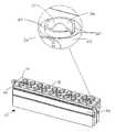
- FIG. 1is a perspective view of a LED lighting apparatus in accordance with this invention, the LED lighting apparatus being a portion of a lighting fixture.
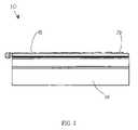
- FIG. 2is a side elevation of the apparatus of FIG. 1 .
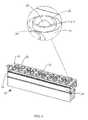
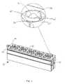
- FIG. 3is an exploded perspective view of a lighting apparatus of FIG. 1 .
- FIG. 4is a front elevation with an enlarged portion of the apparatus of FIG. 1 .
- FIG. 5is a front elevation with an enlarged portion of the apparatus of FIG. 1 .
- FIG. 6is a front elevation with an enlarged portion of the apparatus of FIG. 1 .
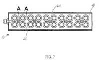
- FIG. 7is a top view of the lighting apparatus of FIG. 1 .
- FIG. 8is a sectional view taken along section A-A as indicated in FIG. 7 .
- FIG. 9is a top view of the lighting apparatus of FIG. 1 .
- FIG. 10is a sectional view taken along section B-B as indicated in FIG. 9 .
- FIGS. 11-12are perspective views of one of the secondary lenses of the apparatus of FIG. 1 , primarily illustrating the outer lens surface of the secondary lens.
- FIG. 13is a schematic perspective representation of a light pole mounting a lighting fixture including the inventive LED apparatus therein; the pole is positioned along the side of a roadway.
- FIG. 14is a two-dimensional illumination intensity distribution of a lighting fixture such as in FIG. 13 having lighting apparatus as described but without the shielding layer. It does not represent the invention, but is not prior art.
- FIG. 15is a two-dimensional illumination intensity distribution of a lighting fixture such as in FIG. 13 having lighting apparatus as described with the shielding layer.
- FIGS. 1-7 , 9 and 13illustrate an LED apparatus 10 for illumination toward a preferential side 36 in a downward direction 48 and outward direction 49 and for accommodating LED lens(es) 16 , 20 movement and providing a weather-proof seal.
- LED apparatus 10includes a mounting board 12 , LED package 14 thereon with primary lens 16 having central axis 18 , and secondary lens member 20 over primary lens 16 and establishing light path 22 therebetween.
- Mounting board 12is connected to heat sink 54 as shown in FIGS. 1-6 .
- One or more, typically several, LED packages 14are arranged on a mounting board 12 to form what is referred to as an LED module 58 as illustrated in FIG. 1 .
- One or more LED modules 58are used as the light source for various innovative lighting fixtures.
- shield member 24in the form of a layer, is positioned over mounting board 12 , LED package 14 and secondary lens member 20 .
- Shield-gasket member 24has shield portion 26 and a substantially planar gasket portion 28 thereabout as seen in FIGS. 3 , 5 - 6 , 8 and 10 .
- FIGS. 8-10illustrate that shield-gasket member 24 has a shield-member aperture 30 aligned with light path 22 and shield portion 26 borders shield-member aperture 30 .
- secondary lens 20includes a lens portion 32 which is substantially transparent and a flange 34 portion thereabout. Lens portions 32 is adjacent to flange portion 34 as illustrated in FIGS. 11 and 12 .
- Shield portion 26can extend over a part of lens portion 32 of secondary lens member 20 as illustrated in FIG. 10 As seen in FIG. 10 shield portion 26 blocks a portion of the light path 22 .
- Secondary lens member 20is asymmetrical and has an illumination pattern 50 with a preferential side 36 and a non-preferential side 38 as shown in FIGS. 13-15 . Shield portion 26 is positioned to intercept light on non-preferential side 38 .
- FIG. 8illustrates shield portion 26 which is positioned to block a portion of light path 22 (shield portion 26 intercepts light which is located on the sides of light path 22 ) and results in light path 22 being in the form of a beam of light.
- secondary lens 20defines preferential side as indicated by reference number 36 .
- FIGS. 13-15also indicate, by reference number 38 , the direction toward the opposite, non-preferential side 38 .
- FIG. 14-15illustrate a two-dimensional illumination intensity distribution 50 for an embodiment containing an LED package 14 , a single primary lens 16 and a single secondary lens 20 .
- Pattern 50 in FIGS. 14-15was generated using optical ray-tracing software to simulate the illumination intensity emanating from LED apparatus 10 .
- the brightness of illumination pattern 50 in FIG. 15illustrates the relative intensity distribution using a shield-gasket member layer 24 , demonstrating that a very large percentage of the light emanating from apparatus 10 is redirected toward the preferential side 36 by shield/gasket member layer 24 of apparatus 10 and only a small amount of trespass light on the non-preferential side 38 .
- FIG. 14illustrates the relative intensity distribution without the shield-gasket member layer 24 present, demonstrating that light is not blocked from the apparatus 10 resulting in a large amount of trespass light on the non-preferential side 38 .
- FIGS. 1-7 and 9illustrate that cover 40 secures shield member 24 with respect to secondary lens member 20 , primary lens 16 and LED package 14 .
- Cover 40has an opening 42 aligned with light path 22 as shown in FIG. 3 .
- Shield-gasket member 24is sandwiched between cover 40 and flange 34 of secondary lens member 20 as illustrated in FIG. 3 .
- flange 34 of secondary lens member 20is sandwiched against mounting board 12 .
- Gasket portion 28 of shield-gasket layer 24is against secondary lens member 20 in position other than in light path 22 .
- Gasket portion 28is yieldingly constraining secondary lens member 20 and accommodating secondary lens member 20 movement caused by primary lens 16 thermal expansion during operation.
- Shield-gasket layer 24has a plurality of shield member apertures 30 .
- the gasket portion 28is made from closed-cell silicone which is soft but solid silicone that is not porous. Gasket portion 28 may also be made from any non-porous material which may be tailored for gasket use.
- Each shield-gasket layer 24can have a plurality of shield members 26 on a single gasket portion 28 as illustrated in FIG. 3 .
- LED apparatus 10can consist of only one LED package 14 on a mounting board 12 with a corresponding primary lens 16 , secondary lens member 20 and shield-gasket member 24 or it can consist of plurality of LED packages 14 on mounting board 12 with corresponding primary lenses 16 , secondary lens members 20 , shield portions 26 and a shield-gasket member 24 .
- a plurality of LED packages 14are spaced from one another on the mounting board 12 .
- a plurality of secondary lens members 20are also present in certain embodiments as illustrated in FIG. 3 .
- Each secondary lens member 20is positioned over the primary lens 16 of a corresponding LED package 14 .
- Each primary-lens/secondary-lens-member pair 52establishes a light path 22 and has a central axis 18 as shown in FIGS. 8 and 10 .
- a plurality of shield portions 26 of the shield-gasket member 24are also present in certain embodiments as illustrated in FIG. 3 .
- shield portion 26can be positioned partially over each primary-lens/secondary-lens-member pair 52 thereby to intercept a portion of the light path 22 emitted from the corresponding LED package 14 .
- shield portion 26can have a substantially annular shape which causes shield portion 26 to intercept a portion of light path 22 .
- Shield portion 26in one embodiment has a substantially annular shape.
- the substantially annular shield portion 26includes at least one gap 60 thereby to facilitate drainage of water as illustrated in FIG. 5 .
- a plurality of substantially annular shield portions 26include a plurality of gaps 60 which are oriented in the same direction to facilitate drainage of water or other liquid.
- shield portion 26 of shield-gasket member 24has a reflective surface 44 facing secondary lens member 20 .
- Another embodiment of the LED apparatus 10is includes nomex layer 62 for electrical insulation purposes sandwiched between secondary lens member 20 and mounting hoard 12 as shown in FIG. 3 .
- a highly preferred embodiment of LED apparatus 10includes aluminum layer 56 sandwiched between mounting board 12 and secondary lens member 20 as seen in FIG. 3 .
- Another highly preferred embodimentincludes both a nomex® layer 62 and aluminum layer 56 , both layers being sandwiched between mounting board 12 and secondary lens member 20 (as illustrated in FIG. 3 ).
- Nomex®is a flame resistant meta-aramid material.
- FR4Flame Resistant 4
- the conductor layermay be made of any suitable conductive material, preferably copper or aluminum 56 .
- FR4Flame Resistant 4
- Such mounting boardinclude, for each LED package thereon, a plurality of channels (“thermal vias”) extending through the mounting board at positions beneath the package, such channels having therein conductive material and/or an opening to facilitate transfer of heat through the board.
- the thermal viasprovide an isolated thermal path for each LED package.
- each LED packageis constructed to have its cathode terminal electrically neutral from the thermal path. Thus, avoiding shortage of other LED packages on the board.
Landscapes
- Engineering & Computer Science (AREA)
- General Engineering & Computer Science (AREA)
- Physics & Mathematics (AREA)
- General Physics & Mathematics (AREA)
- Theoretical Computer Science (AREA)
- Arrangement Of Elements, Cooling, Sealing, Or The Like Of Lighting Devices (AREA)
Abstract
Description
Claims (21)
Priority Applications (1)
| Application Number | Priority Date | Filing Date | Title |
|---|---|---|---|
| US12/107,138US7637630B2 (en) | 2008-04-22 | 2008-04-22 | Integrated shield-gasket member in LED apparatus |
Applications Claiming Priority (1)
| Application Number | Priority Date | Filing Date | Title |
|---|---|---|---|
| US12/107,138US7637630B2 (en) | 2008-04-22 | 2008-04-22 | Integrated shield-gasket member in LED apparatus |
Publications (2)
| Publication Number | Publication Date |
|---|---|
| US20090262532A1 US20090262532A1 (en) | 2009-10-22 |
| US7637630B2true US7637630B2 (en) | 2009-12-29 |
Family
ID=41200965
Family Applications (1)
| Application Number | Title | Priority Date | Filing Date |
|---|---|---|---|
| US12/107,138Active2028-04-25US7637630B2 (en) | 2008-04-22 | 2008-04-22 | Integrated shield-gasket member in LED apparatus |
Country Status (1)
| Country | Link |
|---|---|
| US (1) | US7637630B2 (en) |
Cited By (37)
| Publication number | Priority date | Publication date | Assignee | Title |
|---|---|---|---|---|
| US20080272380A1 (en)* | 2007-05-03 | 2008-11-06 | Ruud Lighting, Inc. | Shield Member in LED Apparatus |
| US20100110671A1 (en)* | 2008-05-16 | 2010-05-06 | Musco Corporation | Method, system, and apparatus for highly controlled light distribution from light fixture using multiple light sources (leds) |
| US7766509B1 (en)* | 2008-06-13 | 2010-08-03 | Lumec Inc. | Orientable lens for an LED fixture |
| US20100195333A1 (en)* | 2009-01-30 | 2010-08-05 | Gary Eugene Schaefer | Led optical assembly |
| US20100271829A1 (en)* | 2008-06-13 | 2010-10-28 | Lumec Inc. | Orientable lens for a led fixture |
| US20110128741A1 (en)* | 2009-11-30 | 2011-06-02 | Ge Investment Co., Ltd. | Lighting apparatus |
| US20110242807A1 (en)* | 2010-03-31 | 2011-10-06 | Aphos Lighting Llc | Light cover and illuminating apparatus applying the same |
| USD663462S1 (en) | 2011-05-13 | 2012-07-10 | Abl Ip Holding Llc | Light fixture |
| USD670856S1 (en) | 2011-11-17 | 2012-11-13 | Abl Ip Holding Llc | Light fixture |
| USD670857S1 (en) | 2011-11-17 | 2012-11-13 | Abl Ip Holding Llc | Light fixture |
| USD673307S1 (en) | 2011-05-12 | 2012-12-25 | Cooper Technologies Company | Light bar |
| US20130021798A1 (en)* | 2011-07-22 | 2013-01-24 | Excellence Optoelectronics Inc. | Light shielding plate of outdoor led lighting device |
| US20130051020A1 (en)* | 2011-08-26 | 2013-02-28 | Nichia Corporation | Led light emitting apparatus |
| US20130148332A1 (en)* | 2010-09-15 | 2013-06-13 | Sharp Kabushiki Kaisha | Illumination device and display device |
| US8622569B1 (en) | 2009-07-17 | 2014-01-07 | Musco Corporation | Method, system and apparatus for controlling light distribution using swivel-mount led light sources |
| US20140016318A1 (en)* | 2012-07-11 | 2014-01-16 | Stevan Pokrajac | LED Light Assembly |
| US8801221B2 (en) | 2012-01-06 | 2014-08-12 | Young Lighting Technology Inc. | Lens structure, light source device and light source module |
| US20140226339A1 (en)* | 2013-02-11 | 2014-08-14 | Cree, Inc. | Led light fixture with integrated light shielding |
| US8992047B2 (en) | 2008-05-16 | 2015-03-31 | Musco Corporation | Apparatus, method, and system for highly controlled light distribution using multiple light sources |
| US9028087B2 (en) | 2006-09-30 | 2015-05-12 | Cree, Inc. | LED light fixture |
| US9039223B2 (en) | 2006-09-30 | 2015-05-26 | Cree, Inc. | LED lighting fixture |
| US20150146424A1 (en)* | 2012-06-22 | 2015-05-28 | Dcg Systems, Inc. | Led lighting device |
| US9046250B2 (en) | 2011-03-03 | 2015-06-02 | Koninklijke Philips N.V. | Circuit board assembly that includes plural LEDs electrically connected to underlying pads |
| US20150252972A1 (en)* | 2012-11-27 | 2015-09-10 | Huizhou Arrlux Optoelectronic Co., Ltd. | Modular led street light and led light source module |
| US9222632B2 (en) | 2013-01-31 | 2015-12-29 | Cree, Inc. | LED lighting fixture |
| US9400087B2 (en) | 2013-03-12 | 2016-07-26 | Abl Ip Holding Llc | Externally mounted shield for LED luminaire |
| US9435519B2 (en) | 2013-01-31 | 2016-09-06 | Cree, Inc. | Light-fixture support assembly |
| US9470394B2 (en)* | 2014-11-24 | 2016-10-18 | Cree, Inc. | LED light fixture including optical member with in-situ-formed gasket and method of manufacture |
| US9541246B2 (en) | 2006-09-30 | 2017-01-10 | Cree, Inc. | Aerodynamic LED light fixture |
| US20190139465A1 (en)* | 2012-07-30 | 2019-05-09 | Ultravision Technologies, Llc | Light Assembly with Transparent Substrate Overlying LEDs Attached to a Circuit Board |
| US20190368673A1 (en)* | 2018-05-30 | 2019-12-05 | Seoul Semiconductor Co., Ltd. | Light emitting device module |
| US10741107B2 (en) | 2013-12-31 | 2020-08-11 | Ultravision Technologies, Llc | Modular display panel |
| US11131439B2 (en)* | 2017-09-28 | 2021-09-28 | Opple Lighting Co., Ltd. | Lighting device |
| US11511527B2 (en) | 2020-04-14 | 2022-11-29 | Saint-Gobain Performance Plastics Corporation | Composite film |
| US20240175563A1 (en)* | 2020-10-29 | 2024-05-30 | Bitro Group, Inc. | Led lens based lighting device |
| US12018833B1 (en) | 2023-06-30 | 2024-06-25 | Creeled, Inc. | Asymmetric LED optic for asymmetric luminaire applications |
| US12442508B2 (en)* | 2024-02-05 | 2025-10-14 | Bitro Group, Inc. | LED device with perforated panel having lenses |
Families Citing this family (22)
| Publication number | Priority date | Publication date | Assignee | Title |
|---|---|---|---|---|
| US9404634B2 (en)* | 2009-10-30 | 2016-08-02 | Cree, Inc. | LED light fixture with facilitated lensing alignment and method of manufacture |
| US9028097B2 (en) | 2009-10-30 | 2015-05-12 | Cree, Inc. | LED apparatus and method for accurate lens alignment |
| KR101047778B1 (en)* | 2010-04-01 | 2011-07-07 | 엘지이노텍 주식회사 | Light emitting device package and light unit having same |
| EP2375130B1 (en)* | 2010-04-09 | 2014-07-02 | Thorn Europhane S.A. | Lighting module for tunnel, road or street light |
| US8419217B2 (en)* | 2011-01-21 | 2013-04-16 | Hergy Lighting Technology Corp. | LED lamp |
| WO2013044877A1 (en)* | 2011-09-30 | 2013-04-04 | 深圳市邦贝尔电子有限公司 | Led light source module |
| CN103032700A (en)* | 2011-09-30 | 2013-04-10 | 深圳市邦贝尔电子有限公司 | Light-emitting diode (LED) light source provided with pressing frame |
| US9157606B2 (en)* | 2012-02-22 | 2015-10-13 | Koninklije Philips N.V. | Optical system for LEDs for control of stray light |
| US20140063802A1 (en)* | 2012-08-31 | 2014-03-06 | Koninklijke Philips Electronics N.V. | Optical System for LEDs for Controlling Light Utilizing Reflectors |
| US9080739B1 (en)* | 2012-09-14 | 2015-07-14 | Cooper Technologies Company | System for producing a slender illumination pattern from a light emitting diode |
| JP6186904B2 (en) | 2013-06-05 | 2017-08-30 | 日亜化学工業株式会社 | Light emitting device |
| USD751240S1 (en)* | 2013-11-01 | 2016-03-08 | Cree, Inc. | Light fixture |
| USD786458S1 (en)* | 2014-08-07 | 2017-05-09 | Epistar Corporation | Light emitting diode filament |
| EP3118842B1 (en)* | 2015-07-14 | 2020-10-14 | CCS Care Communication Solutions GmbH | Corridor indicator lamp comprising an extension unit |
| US10151435B2 (en) | 2016-04-09 | 2018-12-11 | Tempo Industries, Llc | Adaptive LED cove lighting system |
| US10352509B2 (en) | 2016-04-09 | 2019-07-16 | Tempo Industries, Llc | Adaptive LED cove lighting system with micro baffle |
| US10222012B2 (en)* | 2016-08-08 | 2019-03-05 | Tempo Industries, Llc | Ceiling-based LED auditorium pathway lighting apparatus |
| US10451264B2 (en) | 2018-03-20 | 2019-10-22 | Tempo Industries, Llc | Water resistant LED light fixtures |
| WO2020030302A1 (en)* | 2018-08-10 | 2020-02-13 | Eaton Intelligent Power Limited | Integrated louvres for beam control in an led lighting device |
| US10721806B1 (en) | 2019-03-29 | 2020-07-21 | Tempo Industries, Llc | Auditorium house light positioning system |
| NL2023295B1 (en)* | 2019-06-12 | 2021-01-21 | Schreder Sa | Light emitting device with adaptable glare class |
| US20250003575A1 (en)* | 2023-06-30 | 2025-01-02 | Korrus, Inc. | Lighting devices, light distribution-modifying elements, and methods |
Citations (39)
| Publication number | Priority date | Publication date | Assignee | Title |
|---|---|---|---|---|
| US4254453A (en) | 1978-08-25 | 1981-03-03 | General Instrument Corporation | Alpha-numeric display array and method of manufacture |
| US5066889A (en) | 1989-07-01 | 1991-11-19 | Oxley Developments Company Limited | Sealed led lamp housing |
| US5274250A (en) | 1991-07-12 | 1993-12-28 | Fuji Xerox Co., Ltd. | Color image sensor with light-shielding layer |
| US5711890A (en) | 1996-03-11 | 1998-01-27 | Eastman Kodak Company | Method for forming cylindrical lens arrays for solid state imager |
| US5796154A (en) | 1995-05-22 | 1998-08-18 | Matsushita Electronics Corporation | Solid-state imaging device with dual lens structure |
| US5848839A (en) | 1997-04-07 | 1998-12-15 | Savage, Jr.; John M. | LED sealing lens cap and retainer |
| US5984494A (en) | 1995-09-08 | 1999-11-16 | Jimmy G. Cook | Light shield for an illumination system |
| US6325524B1 (en) | 1999-01-29 | 2001-12-04 | Agilent Technologies, Inc. | Solid state based illumination source for a projection display |
| US6414343B1 (en) | 1999-10-07 | 2002-07-02 | Fuji Photo Film., Ltd. | Solid-state imaging device having aspheric lenses |
| US6630736B1 (en) | 2000-07-27 | 2003-10-07 | National Semiconductor Corporation | Light barrier for light sensitive semiconductor devices |
| US6635911B2 (en) | 1999-12-28 | 2003-10-21 | Sony Corporation | Solid state image sensing device |
| US6635941B2 (en) | 2001-03-21 | 2003-10-21 | Canon Kabushiki Kaisha | Structure of semiconductor device with improved reliability |
| US20040052077A1 (en) | 2001-09-25 | 2004-03-18 | Kelvin Shih | Light emitting diode with integrated heat dissipater |
| US6730940B1 (en) | 2002-10-29 | 2004-05-04 | Lumileds Lighting U.S., Llc | Enhanced brightness light emitting device spot emitter |
| US20040156209A1 (en) | 2003-02-10 | 2004-08-12 | Hiroyuki Ishida | Vehicular headlamp and optical unit |
| US20040160782A1 (en)* | 2000-12-16 | 2004-08-19 | Schefenacker Vision Systems Germany Gmbh + Co. Kg | Vehicle light for a vehicle, preferably a motor vehicle |
| US6837605B2 (en) | 2001-11-28 | 2005-01-04 | Osram Opto Semiconductors Gmbh | Led illumination system |
| US20050013139A1 (en)* | 2001-11-28 | 2005-01-20 | Toyoda Gosei Co., Ltd. | Illumination device |
| US6876008B2 (en) | 2003-07-31 | 2005-04-05 | Lumileds Lighting U.S., Llc | Mount for semiconductor light emitting device |
| US6972439B1 (en) | 2004-05-27 | 2005-12-06 | Samsung Electro-Mechanics Co., Ltd. | Light emitting diode device |
| US7009213B2 (en) | 2003-07-31 | 2006-03-07 | Lumileds Lighting U.S., Llc | Light emitting devices with improved light extraction efficiency |
| US7019334B2 (en) | 2003-06-13 | 2006-03-28 | Stanley Electric Co., Ltd. | LED lamp for light source of a headlamp |
| US7078258B2 (en) | 2003-05-30 | 2006-07-18 | Matsushita Electric Industrial Co., Ltd. | Image sensor and manufacturing method of image sensor |
| US20060158080A1 (en) | 2005-01-19 | 2006-07-20 | Nichia Corporation | Surface light emitting apparatus |
| US7080932B2 (en) | 2004-01-26 | 2006-07-25 | Philips Lumileds Lighting Company, Llc | LED with an optical system to increase luminance by recycling emitted light |
| US20060169878A1 (en) | 2005-01-17 | 2006-08-03 | Masahiro Kasano | Solid-state imaging device and manufacturing method for the same |
| US20060175626A1 (en) | 2005-02-07 | 2006-08-10 | Lumileds Lighting U.S., Llc | Beam shutter in LED package |
| US7102185B2 (en) | 2004-06-21 | 2006-09-05 | Eastman Kodak Company | Lightshield architecture for interline transfer image sensors |
| US20060256573A1 (en)* | 2005-05-11 | 2006-11-16 | Ko-Chuh Pan | Compound rear light device |
| US7141825B2 (en) | 2004-03-29 | 2006-11-28 | Stanley Electric Co., Ltd. | Semiconductor light emitting device capable of suppressing silver migration of reflection film made of silver |
| US7176070B2 (en) | 2002-05-01 | 2007-02-13 | Au Optronics Corp. | Active matrix organic light emitting display and method of forming the same |
| US7182480B2 (en) | 2003-03-05 | 2007-02-27 | Tir Systems Ltd. | System and method for manipulating illumination created by an array of light emitting devices |
| US20070070625A1 (en) | 2005-09-23 | 2007-03-29 | Lg.Philips Lcd Co., Ltd. | Backlight assembly and liquid crystal display module using the same |
| US20070097684A1 (en) | 2003-09-19 | 2007-05-03 | Kunihiko Obara | Lighting apparatus |
| US20070189005A1 (en)* | 2003-03-25 | 2007-08-16 | Chapman Leonard T | Flashlight |
| US7281818B2 (en) | 2003-12-11 | 2007-10-16 | Dialight Corporation | Light reflector device for light emitting diode (LED) array |
| US20070285915A1 (en)* | 2006-06-09 | 2007-12-13 | Paul Rosenau | Fitting and method of installation |
| US20080266852A1 (en)* | 2007-04-30 | 2008-10-30 | Honeywell International, Inc. | Backlight for a display device with improved filtering and method for constructing the same |
| US20090003009A1 (en)* | 2007-06-30 | 2009-01-01 | Thomas Tessnow | LED lamp module |
- 2008
- 2008-04-22USUS12/107,138patent/US7637630B2/enactiveActive
Patent Citations (41)
| Publication number | Priority date | Publication date | Assignee | Title |
|---|---|---|---|---|
| US4254453A (en) | 1978-08-25 | 1981-03-03 | General Instrument Corporation | Alpha-numeric display array and method of manufacture |
| US5066889A (en) | 1989-07-01 | 1991-11-19 | Oxley Developments Company Limited | Sealed led lamp housing |
| US5274250A (en) | 1991-07-12 | 1993-12-28 | Fuji Xerox Co., Ltd. | Color image sensor with light-shielding layer |
| US5796154A (en) | 1995-05-22 | 1998-08-18 | Matsushita Electronics Corporation | Solid-state imaging device with dual lens structure |
| US5984494A (en) | 1995-09-08 | 1999-11-16 | Jimmy G. Cook | Light shield for an illumination system |
| US5711890A (en) | 1996-03-11 | 1998-01-27 | Eastman Kodak Company | Method for forming cylindrical lens arrays for solid state imager |
| US5848839A (en) | 1997-04-07 | 1998-12-15 | Savage, Jr.; John M. | LED sealing lens cap and retainer |
| US6325524B1 (en) | 1999-01-29 | 2001-12-04 | Agilent Technologies, Inc. | Solid state based illumination source for a projection display |
| US6414343B1 (en) | 1999-10-07 | 2002-07-02 | Fuji Photo Film., Ltd. | Solid-state imaging device having aspheric lenses |
| US6635911B2 (en) | 1999-12-28 | 2003-10-21 | Sony Corporation | Solid state image sensing device |
| US6630736B1 (en) | 2000-07-27 | 2003-10-07 | National Semiconductor Corporation | Light barrier for light sensitive semiconductor devices |
| US20040160782A1 (en)* | 2000-12-16 | 2004-08-19 | Schefenacker Vision Systems Germany Gmbh + Co. Kg | Vehicle light for a vehicle, preferably a motor vehicle |
| US6635941B2 (en) | 2001-03-21 | 2003-10-21 | Canon Kabushiki Kaisha | Structure of semiconductor device with improved reliability |
| US6893941B2 (en) | 2001-03-21 | 2005-05-17 | Canon Kabushiki Kaisha | Semiconductor device and its manufacture method |
| US20040052077A1 (en) | 2001-09-25 | 2004-03-18 | Kelvin Shih | Light emitting diode with integrated heat dissipater |
| US6837605B2 (en) | 2001-11-28 | 2005-01-04 | Osram Opto Semiconductors Gmbh | Led illumination system |
| US20050013139A1 (en)* | 2001-11-28 | 2005-01-20 | Toyoda Gosei Co., Ltd. | Illumination device |
| US7176070B2 (en) | 2002-05-01 | 2007-02-13 | Au Optronics Corp. | Active matrix organic light emitting display and method of forming the same |
| US6969946B2 (en) | 2002-10-29 | 2005-11-29 | Lumileds Lighting U.S., Llc | Enhanced brightness light emitting device spot emitter |
| US6730940B1 (en) | 2002-10-29 | 2004-05-04 | Lumileds Lighting U.S., Llc | Enhanced brightness light emitting device spot emitter |
| US20040156209A1 (en) | 2003-02-10 | 2004-08-12 | Hiroyuki Ishida | Vehicular headlamp and optical unit |
| US7182480B2 (en) | 2003-03-05 | 2007-02-27 | Tir Systems Ltd. | System and method for manipulating illumination created by an array of light emitting devices |
| US20070189005A1 (en)* | 2003-03-25 | 2007-08-16 | Chapman Leonard T | Flashlight |
| US7078258B2 (en) | 2003-05-30 | 2006-07-18 | Matsushita Electric Industrial Co., Ltd. | Image sensor and manufacturing method of image sensor |
| US7019334B2 (en) | 2003-06-13 | 2006-03-28 | Stanley Electric Co., Ltd. | LED lamp for light source of a headlamp |
| US7009213B2 (en) | 2003-07-31 | 2006-03-07 | Lumileds Lighting U.S., Llc | Light emitting devices with improved light extraction efficiency |
| US6876008B2 (en) | 2003-07-31 | 2005-04-05 | Lumileds Lighting U.S., Llc | Mount for semiconductor light emitting device |
| US20070097684A1 (en) | 2003-09-19 | 2007-05-03 | Kunihiko Obara | Lighting apparatus |
| US7281818B2 (en) | 2003-12-11 | 2007-10-16 | Dialight Corporation | Light reflector device for light emitting diode (LED) array |
| US7080932B2 (en) | 2004-01-26 | 2006-07-25 | Philips Lumileds Lighting Company, Llc | LED with an optical system to increase luminance by recycling emitted light |
| US7141825B2 (en) | 2004-03-29 | 2006-11-28 | Stanley Electric Co., Ltd. | Semiconductor light emitting device capable of suppressing silver migration of reflection film made of silver |
| US6972439B1 (en) | 2004-05-27 | 2005-12-06 | Samsung Electro-Mechanics Co., Ltd. | Light emitting diode device |
| US7102185B2 (en) | 2004-06-21 | 2006-09-05 | Eastman Kodak Company | Lightshield architecture for interline transfer image sensors |
| US20060169878A1 (en) | 2005-01-17 | 2006-08-03 | Masahiro Kasano | Solid-state imaging device and manufacturing method for the same |
| US20060158080A1 (en) | 2005-01-19 | 2006-07-20 | Nichia Corporation | Surface light emitting apparatus |
| US20060175626A1 (en) | 2005-02-07 | 2006-08-10 | Lumileds Lighting U.S., Llc | Beam shutter in LED package |
| US20060256573A1 (en)* | 2005-05-11 | 2006-11-16 | Ko-Chuh Pan | Compound rear light device |
| US20070070625A1 (en) | 2005-09-23 | 2007-03-29 | Lg.Philips Lcd Co., Ltd. | Backlight assembly and liquid crystal display module using the same |
| US20070285915A1 (en)* | 2006-06-09 | 2007-12-13 | Paul Rosenau | Fitting and method of installation |
| US20080266852A1 (en)* | 2007-04-30 | 2008-10-30 | Honeywell International, Inc. | Backlight for a display device with improved filtering and method for constructing the same |
| US20090003009A1 (en)* | 2007-06-30 | 2009-01-01 | Thomas Tessnow | LED lamp module |
Cited By (51)
| Publication number | Priority date | Publication date | Assignee | Title |
|---|---|---|---|---|
| US9541246B2 (en) | 2006-09-30 | 2017-01-10 | Cree, Inc. | Aerodynamic LED light fixture |
| US9534775B2 (en) | 2006-09-30 | 2017-01-03 | Cree, Inc. | LED light fixture |
| US9261270B2 (en) | 2006-09-30 | 2016-02-16 | Cree, Inc. | LED lighting fixture |
| US9039223B2 (en) | 2006-09-30 | 2015-05-26 | Cree, Inc. | LED lighting fixture |
| US9028087B2 (en) | 2006-09-30 | 2015-05-12 | Cree, Inc. | LED light fixture |
| US8092042B2 (en)* | 2007-05-03 | 2012-01-10 | Ruud Lighting, Inc. | Shield member in LED apparatus |
| US20080272380A1 (en)* | 2007-05-03 | 2008-11-06 | Ruud Lighting, Inc. | Shield Member in LED Apparatus |
| US8992047B2 (en) | 2008-05-16 | 2015-03-31 | Musco Corporation | Apparatus, method, and system for highly controlled light distribution using multiple light sources |
| US20100110671A1 (en)* | 2008-05-16 | 2010-05-06 | Musco Corporation | Method, system, and apparatus for highly controlled light distribution from light fixture using multiple light sources (leds) |
| US8602588B2 (en) | 2008-05-16 | 2013-12-10 | Musco Corporation | Method, system, and apparatus for highly controlled light distribution from light fixture using multiple light sources (LEDs) |
| US7766509B1 (en)* | 2008-06-13 | 2010-08-03 | Lumec Inc. | Orientable lens for an LED fixture |
| US20100271829A1 (en)* | 2008-06-13 | 2010-10-28 | Lumec Inc. | Orientable lens for a led fixture |
| US7959326B2 (en) | 2008-06-13 | 2011-06-14 | Philips Electronics Ltd | Orientable lens for a LED fixture |
| US8246212B2 (en)* | 2009-01-30 | 2012-08-21 | Koninklijke Philips Electronics N.V. | LED optical assembly |
| US20100195333A1 (en)* | 2009-01-30 | 2010-08-05 | Gary Eugene Schaefer | Led optical assembly |
| US8622569B1 (en) | 2009-07-17 | 2014-01-07 | Musco Corporation | Method, system and apparatus for controlling light distribution using swivel-mount led light sources |
| US20110128741A1 (en)* | 2009-11-30 | 2011-06-02 | Ge Investment Co., Ltd. | Lighting apparatus |
| US20110242807A1 (en)* | 2010-03-31 | 2011-10-06 | Aphos Lighting Llc | Light cover and illuminating apparatus applying the same |
| US20130148332A1 (en)* | 2010-09-15 | 2013-06-13 | Sharp Kabushiki Kaisha | Illumination device and display device |
| US9046250B2 (en) | 2011-03-03 | 2015-06-02 | Koninklijke Philips N.V. | Circuit board assembly that includes plural LEDs electrically connected to underlying pads |
| USD673307S1 (en) | 2011-05-12 | 2012-12-25 | Cooper Technologies Company | Light bar |
| USD663462S1 (en) | 2011-05-13 | 2012-07-10 | Abl Ip Holding Llc | Light fixture |
| USD672492S1 (en) | 2011-05-13 | 2012-12-11 | Abl Ip Holding Llc | Light fixture |
| US20130021798A1 (en)* | 2011-07-22 | 2013-01-24 | Excellence Optoelectronics Inc. | Light shielding plate of outdoor led lighting device |
| US20130051020A1 (en)* | 2011-08-26 | 2013-02-28 | Nichia Corporation | Led light emitting apparatus |
| US8864336B2 (en)* | 2011-08-26 | 2014-10-21 | Nichia Corporation | LED light emitting apparatus |
| USD670856S1 (en) | 2011-11-17 | 2012-11-13 | Abl Ip Holding Llc | Light fixture |
| USD670857S1 (en) | 2011-11-17 | 2012-11-13 | Abl Ip Holding Llc | Light fixture |
| US8801221B2 (en) | 2012-01-06 | 2014-08-12 | Young Lighting Technology Inc. | Lens structure, light source device and light source module |
| US20150146424A1 (en)* | 2012-06-22 | 2015-05-28 | Dcg Systems, Inc. | Led lighting device |
| US20140016318A1 (en)* | 2012-07-11 | 2014-01-16 | Stevan Pokrajac | LED Light Assembly |
| US10891881B2 (en) | 2012-07-30 | 2021-01-12 | Ultravision Technologies, Llc | Lighting assembly with LEDs and optical elements |
| US10460634B2 (en)* | 2012-07-30 | 2019-10-29 | Ultravision Technologies, Llc | LED light assembly with transparent substrate having array of lenses for projecting light to illuminate an area |
| US20190139465A1 (en)* | 2012-07-30 | 2019-05-09 | Ultravision Technologies, Llc | Light Assembly with Transparent Substrate Overlying LEDs Attached to a Circuit Board |
| US20150252972A1 (en)* | 2012-11-27 | 2015-09-10 | Huizhou Arrlux Optoelectronic Co., Ltd. | Modular led street light and led light source module |
| US9605819B2 (en)* | 2012-11-27 | 2017-03-28 | Huizhou Arrlux Optoelectronic Co., Ltd. | Street light with modular LED light source |
| US9435519B2 (en) | 2013-01-31 | 2016-09-06 | Cree, Inc. | Light-fixture support assembly |
| US9222632B2 (en) | 2013-01-31 | 2015-12-29 | Cree, Inc. | LED lighting fixture |
| US20140226339A1 (en)* | 2013-02-11 | 2014-08-14 | Cree, Inc. | Led light fixture with integrated light shielding |
| US9212812B2 (en)* | 2013-02-11 | 2015-12-15 | Cree, Inc. | LED light fixture with integrated light shielding |
| US9400087B2 (en) | 2013-03-12 | 2016-07-26 | Abl Ip Holding Llc | Externally mounted shield for LED luminaire |
| US10741107B2 (en) | 2013-12-31 | 2020-08-11 | Ultravision Technologies, Llc | Modular display panel |
| US9470394B2 (en)* | 2014-11-24 | 2016-10-18 | Cree, Inc. | LED light fixture including optical member with in-situ-formed gasket and method of manufacture |
| US11131439B2 (en)* | 2017-09-28 | 2021-09-28 | Opple Lighting Co., Ltd. | Lighting device |
| US10760752B2 (en)* | 2018-05-30 | 2020-09-01 | Seoul Semiconductor Co., Ltd. | Illuminating device having a plurality of asymmetrical lenses mounted to a holder with corresponding asymmetrical openings |
| US20190368673A1 (en)* | 2018-05-30 | 2019-12-05 | Seoul Semiconductor Co., Ltd. | Light emitting device module |
| US11511527B2 (en) | 2020-04-14 | 2022-11-29 | Saint-Gobain Performance Plastics Corporation | Composite film |
| US11813822B2 (en) | 2020-04-14 | 2023-11-14 | Saint-Gobain Performance Plastics Corporation | Composite film |
| US20240175563A1 (en)* | 2020-10-29 | 2024-05-30 | Bitro Group, Inc. | Led lens based lighting device |
| US12018833B1 (en) | 2023-06-30 | 2024-06-25 | Creeled, Inc. | Asymmetric LED optic for asymmetric luminaire applications |
| US12442508B2 (en)* | 2024-02-05 | 2025-10-14 | Bitro Group, Inc. | LED device with perforated panel having lenses |
Also Published As
| Publication number | Publication date |
|---|---|
| US20090262532A1 (en) | 2009-10-22 |
Similar Documents
| Publication | Publication Date | Title |
|---|---|---|
| US7637630B2 (en) | Integrated shield-gasket member in LED apparatus | |
| CA2622524C (en) | Shield member in led apparatus | |
| CA2685915C (en) | Sealing and thermal accommodation arrangement in led devices | |
| CN101772669B (en) | Street lighting arrangement | |
| CA2795378C (en) | Led luminaire light redirection shield | |
| JP5625203B2 (en) | LED lighting device having block assembly structure | |
| EP2378193B1 (en) | Lighting apparatus using light-emitting diode | |
| JP5147357B2 (en) | Road lighting equipment | |
| US8476813B2 (en) | Lamp device | |
| KR102200073B1 (en) | Light emitting module and lighting apparatus having thereof | |
| KR100978105B1 (en) | Lighting device using light emitting diode | |
| AU2014367936B2 (en) | Illumination device | |
| EP2829787A1 (en) | Lamp structure | |
| HK1140003A (en) | Shield member in led apparatus | |
| CN104654085A (en) | LED (Light-Emitting Diode) illumination equipment with baffle |
Legal Events
| Date | Code | Title | Description |
|---|---|---|---|
| AS | Assignment | Owner name:RUUD LIGHTING, INC., WISCONSIN Free format text:ASSIGNMENT OF ASSIGNORS INTEREST;ASSIGNORS:WILCOX, KURT S.;RUUD, ALAN J.;REEL/FRAME:020836/0889;SIGNING DATES FROM 20080417 TO 20080418 | |
| STCF | Information on status: patent grant | Free format text:PATENTED CASE | |
| FPAY | Fee payment | Year of fee payment:4 | |
| AS | Assignment | Owner name:CREE, INC., NORTH CAROLINA Free format text:MERGER;ASSIGNOR:RUUD LIGHTING, INC.;REEL/FRAME:033525/0529 Effective date:20121214 | |
| FPAY | Fee payment | Year of fee payment:8 | |
| AS | Assignment | Owner name:IDEAL INDUSTRIES LIGHTING LLC, ILLINOIS Free format text:ASSIGNMENT OF ASSIGNORS INTEREST;ASSIGNOR:CREE, INC.;REEL/FRAME:049880/0524 Effective date:20190513 | |
| MAFP | Maintenance fee payment | Free format text:PAYMENT OF MAINTENANCE FEE, 12TH YEAR, LARGE ENTITY (ORIGINAL EVENT CODE: M1553); ENTITY STATUS OF PATENT OWNER: LARGE ENTITY Year of fee payment:12 | |
| AS | Assignment | Owner name:FGI WORLDWIDE LLC, NEW YORK Free format text:SECURITY INTEREST;ASSIGNOR:IDEAL INDUSTRIES LIGHTING LLC;REEL/FRAME:064897/0413 Effective date:20230908 |