US7636507B2 - Compact blind mateable optical splitter - Google Patents
Compact blind mateable optical splitterDownload PDFInfo
- Publication number
- US7636507B2 US7636507B2US11/213,772US21377205AUS7636507B2US 7636507 B2US7636507 B2US 7636507B2US 21377205 AUS21377205 AUS 21377205AUS 7636507 B2US7636507 B2US 7636507B2
- Authority
- US
- United States
- Prior art keywords
- splitter
- module
- adapter
- housing
- splitter module
- Prior art date
- Legal status (The legal status is an assumption and is not a legal conclusion. Google has not performed a legal analysis and makes no representation as to the accuracy of the status listed.)
- Active, expires
Links
Images


Classifications
- G—PHYSICS
- G02—OPTICS
- G02B—OPTICAL ELEMENTS, SYSTEMS OR APPARATUS
- G02B6/00—Light guides; Structural details of arrangements comprising light guides and other optical elements, e.g. couplings
- G02B6/24—Coupling light guides
- G02B6/36—Mechanical coupling means
- G02B6/38—Mechanical coupling means having fibre to fibre mating means
- G02B6/3807—Dismountable connectors, i.e. comprising plugs
- G02B6/381—Dismountable connectors, i.e. comprising plugs of the ferrule type, e.g. fibre ends embedded in ferrules, connecting a pair of fibres
- G02B6/3825—Dismountable connectors, i.e. comprising plugs of the ferrule type, e.g. fibre ends embedded in ferrules, connecting a pair of fibres with an intermediate part, e.g. adapter, receptacle, linking two plugs
- G—PHYSICS
- G02—OPTICS
- G02B—OPTICAL ELEMENTS, SYSTEMS OR APPARATUS
- G02B6/00—Light guides; Structural details of arrangements comprising light guides and other optical elements, e.g. couplings
- G02B6/24—Coupling light guides
- G02B6/36—Mechanical coupling means
- G—PHYSICS
- G02—OPTICS
- G02B—OPTICAL ELEMENTS, SYSTEMS OR APPARATUS
- G02B6/00—Light guides; Structural details of arrangements comprising light guides and other optical elements, e.g. couplings
- G02B6/24—Coupling light guides
- G02B6/36—Mechanical coupling means
- G02B6/38—Mechanical coupling means having fibre to fibre mating means
- G02B6/3807—Dismountable connectors, i.e. comprising plugs
- G02B6/3873—Connectors using guide surfaces for aligning ferrule ends, e.g. tubes, sleeves, V-grooves, rods, pins, balls
- G02B6/3874—Connectors using guide surfaces for aligning ferrule ends, e.g. tubes, sleeves, V-grooves, rods, pins, balls using tubes, sleeves to align ferrules
- G02B6/3878—Connectors using guide surfaces for aligning ferrule ends, e.g. tubes, sleeves, V-grooves, rods, pins, balls using tubes, sleeves to align ferrules comprising a plurality of ferrules, branching and break-out means
- G02B6/3879—Linking of individual connector plugs to an overconnector, e.g. using clamps, clips, common housings comprising several individual connector plugs
- G—PHYSICS
- G02—OPTICS
- G02B—OPTICAL ELEMENTS, SYSTEMS OR APPARATUS
- G02B6/00—Light guides; Structural details of arrangements comprising light guides and other optical elements, e.g. couplings
- G02B6/24—Coupling light guides
- G02B6/36—Mechanical coupling means
- G02B6/38—Mechanical coupling means having fibre to fibre mating means
- G02B6/3807—Dismountable connectors, i.e. comprising plugs
- G02B6/3887—Anchoring optical cables to connector housings, e.g. strain relief features
- G02B6/38875—Protection from bending or twisting
- G—PHYSICS
- G02—OPTICS
- G02B—OPTICAL ELEMENTS, SYSTEMS OR APPARATUS
- G02B6/00—Light guides; Structural details of arrangements comprising light guides and other optical elements, e.g. couplings
- G02B6/24—Coupling light guides
- G02B6/26—Optical coupling means
- G02B6/28—Optical coupling means having data bus means, i.e. plural waveguides interconnected and providing an inherently bidirectional system by mixing and splitting signals
- G02B6/2804—Optical coupling means having data bus means, i.e. plural waveguides interconnected and providing an inherently bidirectional system by mixing and splitting signals forming multipart couplers without wavelength selective elements, e.g. "T" couplers, star couplers
- G—PHYSICS
- G02—OPTICS
- G02B—OPTICAL ELEMENTS, SYSTEMS OR APPARATUS
- G02B6/00—Light guides; Structural details of arrangements comprising light guides and other optical elements, e.g. couplings
- G02B6/24—Coupling light guides
- G02B6/36—Mechanical coupling means
- G02B6/38—Mechanical coupling means having fibre to fibre mating means
- G02B6/3807—Dismountable connectors, i.e. comprising plugs
- G02B6/3833—Details of mounting fibres in ferrules; Assembly methods; Manufacture
- G02B6/3847—Details of mounting fibres in ferrules; Assembly methods; Manufacture with means preventing fibre end damage, e.g. recessed fibre surfaces
- G02B6/3849—Details of mounting fibres in ferrules; Assembly methods; Manufacture with means preventing fibre end damage, e.g. recessed fibre surfaces using mechanical protective elements, e.g. caps, hoods, sealing membranes
Definitions
- the present inventiongenerally relates to the field of optical communications and more specifically to passive optical splitters having a high splitting density.
- Passive optical networksare becoming prevalent in part because service providers want to deliver high bandwidth communication capabilities to customers. Passive optical networks may be desirable for delivering high speed communication data because they may not employ active electronic devices, such as amplifiers and/or repeaters, between a central office and a subscriber termination. The absence of active electronic devices may decrease network complexity and cost and may increase network reliability.
- active electronic devicessuch as amplifiers and/or repeaters
- Passive optical networksmay employ optical splitters to take a signal from an incoming fiber and make it available to a number of output fibers.
- a distribution cablemay include 24 optical fibers and may run from a central office to a distribution location, such as an equipment enclosure. At the equipment enclosure, each fiber in the distribution cable may be split into a number of outgoing fibers via an optical splitter module.
- an optical splittermay split an incoming signal into two outgoing signals.
- Individual optical splittersmay be packaged in a steel tube and multiple optical splitters may be grouped together to provide a desired number of outgoing signals.
- a number of individual optical splittersare grouped together, such as grouping 16 optical splitters together to obtain 32 outgoing fibers, a large volume may be required to house the grouped splitters.
- Individual optical splittersmay be grouped into conventional splitter modules in an attempt to manage the complexity associated with grouping splitters when providing communication services.
- Conventional splitter modulesmay be configured with an input pigtail that is configured to be spliced to a distribution fiber within the enclosure.
- a linesmanmay have to splice the conventional splitter module to an incoming distribution fiber using a field splice.
- Field splicesmay be time consuming to perform properly, prone to problems, such as contamination from dirt and/or misaligned fibers at the splicing location, and/or may require specially trained personnel.
- the individual input pigtailmay be coupled to a number of optical splitters within the conventional splitter module.
- the interior of conventional splitter modulesmay become crowded due to the number of individual optical splitters contained therein and the number of input fibers and output fibers associated with the optical splitters.
- Conventional splitter modulesmay also be configured with a number of output pigtails that may be connected to subscriber terminations via connectors and/or splicing.
- Conventional splitter modulesmay be configured to mount in a chassis within the enclosure.
- Conventional splitter modulesmay be relatively large and may discourage achieving a desired level of connection density within the enclosure.
- a conventional 1:16 or 1:32 splitter modulemay occupy on the order of 30 to 90 cubic inches (cu-in) of space.
- the large size of conventional splitter modulesmay limit connection densities because of the number of splitter modules that can fit inside standard enclosures.
- Passive optical network deploymentsmay benefit from new techniques for coupling optical splitter modules to incoming distribution fibers without using field splices.
- Passive optical networksmay also benefit from optical splitter modules that facilitate achieving higher connection densities within an enclosure as compared to connection densities achieved when using conventional splitter modules.
- a splitter assemblymay include an adapter housing having a first side and a second side and configured to support an adapter in a determined position relative to the housing, where the adapter is configured to receive a first connector on the first side, where the first connector is associated with an incoming optical fiber carrying an incoming optical signal.
- the splitter assemblymay include a splitter module configured to couple to the adapter via the second side using a second connector where the second connector is adapted to receive the incoming optical signal, and make the incoming optical signal available to an output fiber in cooperation with an optical splitter.
- an adapter housingmay include a first opening configured to receive a first adapter that is configured to receive a first input connector via a first end of the first adapter, where the first input connector is associated with a first incoming optical fiber that carries a first incoming optical signal.
- the first adaptermay be configured to make the first incoming optical signal available to an optical splitter via a second end of the first adapter in a manner that facilitates blind mating the second end of the first adapter to a first splitter connector associated with the optical splitter.
- a splitter module guidemay include a housing that includes a first end that is configured to include a first opening to receive a first end of a splitter module that includes an input connector adapted to receive an incoming optical signal.
- the housingmay include a second end configured to include a second opening to receive a first side of an adapter that is adapted to make the incoming optical signal available to the input connector via a blind mated connection.
- a splitter modulemay include a first connector adapted to receive a first incoming optical signal from an adapter.
- the splitter modulemay include a splitter adapted to receive the incoming optical signal via an input fiber and split the incoming optical signal into a group of output signals.
- the splitter modulemay include a group of output fibers adapted to receive the group of output signals from the splitter via a group of proximal ends and to make the output signals available to a destination via a group of distal ends.
- the splitter modulemay include a housing adapted to support the first connector in a position to facilitate blind mating the first connector with the adapter, where the adapter makes the incoming optical signal available to the first connector.
- the housingmay be adapted to support the splitter in an interior region of the housing.
- the housingmay be adapted to support the group of proximal ends of the output fibers, and to engage an interior portion of a splitter module guide to facilitate the blind mating of the adapter to the first connector.
- a latching devicefor use on an optical splitter module that is adapted to receive an optical signal from an adapter.
- the latching devicemay include a coupling surface associated with the optical splitter module, where the coupling surface is adapted to engage a mating surface to maintain the optical splitter module in a determined relationship with a splitter module guide or the adapter.
- a method for configuring an enclosuremay include mounting an adapter housing that includes an adapter having a first side and a second side.
- the methodmay include mounting a splitter module guide in the enclosure.
- the methodmay include coupling a connector associated with a distribution fiber that carries an incoming optical signal to the first side of the adapter to make the incoming optical signal available to the adapter.
- an enclosure for making an optical communication signal available to a subscriber in an optical communications networkmay include means for receiving an incoming optical signal.
- the enclosuremay include means for guiding an optical splitting means to the receiving means to facilitate a blind mated connection between the optical splitting means and the receiving means, where the blind mated connection makes the incoming optical signal available to the splitting means.
- the enclosuremay include means for making a split optical signal available to a subscriber termination, where the subscriber termination is associated with the subscriber.
- FIG. 1illustrates an exemplary system for providing optical communication signals to a subscriber via a splitter assembly consistent with the principles of the invention
- FIG. 2Aillustrates a perspective view of an exemplary implementation of a splitter assembly that includes an adapter housing, a splitter module guide and a splitter module consistent with the principles of the invention
- FIG. 2Billustrates a perspective view of an exemplary implementation of a splitter assembly that includes an adapter housing, a splitter module guide and an implementation of a splitter module that includes a latching device consistent with the principles of the invention
- FIG. 3Aillustrates exemplary components that may be used in an exemplary implementation of an adapter housing consistent with the principles of the invention
- FIG. 3Billustrates an assembled adapter housing consistent with the principles of the invention
- FIG. 3Cillustrates an exemplary implementation of an assembled adapter assembly consistent with the principles of the invention
- FIG. 3Dillustrates a collection of exemplary components that may be used in an adapter assembly consistent with the principles of the invention
- FIG. 4Aillustrates an exemplary splitter module guide consistent with the principles of the invention
- FIG. 4Billustrates a collection of exemplary components that may be used in an exemplary implementation of a splitter module guide consistent with the principles of the invention
- FIG. 5Aillustrates a side view of an exemplary implementation of splitter module 206 consistent with the principles of the invention
- FIG. 5Billustrates a top view of an exemplary implementation of splitter module 206 consistent with the principles of the invention
- FIG. 5Cillustrates an end view showing the inputs to an exemplary implementation of a splitter module consistent with the principles of the invention
- FIG. 6Aillustrates a perspective view of an exemplary implementation of splitter module 206 consistent with the principles of the invention
- FIG. 6Billustrates components that may be used in an exemplary implementation of a splitter module consistent with the principles of the invention
- FIG. 7illustrates an exemplary configuration of components that may be used in an exemplary implementation of a splitter module
- FIGS. 8A and 8Billustrate exemplary latching devices that may be used for coupling a splitter module to an exemplary implementation of a splitter module guide consistent with the principles of the invention
- FIGS. 8C and 8Dillustrate an exemplary retaining device that may be used for coupling a splitter module to an exemplary implementation of a splitter module guide consistent with the principles of the invention
- FIGS. 8E and 8Fillustrate an exemplary retaining device that may be used to couple a splitter module to an exemplary implementation of a splitter module guide consistent with the principles of the invention
- FIG. 8Gillustrates exemplary alignment aides that can be used to facilitate alignment of a splitter module with a splitter module guide consistent with the principles of the invention
- FIGS. 8H-8Killustrate various views of an exemplary lock device that can be used to retain a splitter module in a determined relationship with a splitter module guide consistent with the principles of the invention
- FIG. 9Aillustrates an exemplary arrangement of splitter assemblies supported on an upper shelf consistent with the principles of the invention
- FIG. 9Billustrates an exemplary arrangement of splitter module shelves in a frame suitable for use in an enclosure consistent with the principles of the invention
- FIG. 9Cillustrates an exemplary arrangement of splitter assemblies and subscriber terminations consistent with the principles of the invention.
- FIG. 10illustrates an exemplary method for coupling a distribution fiber to a splitter module consistent with the principles of the invention.
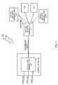
- FIG. 1illustrates an exemplary system for providing optical communication signals to a subscriber via an optical splitter assembly consistent with the principles of the invention.
- System 100may include an optical line terminal (OLT) 102 , a central office 104 , voice 106 , data 108 , video 110 , distribution fiber 111 , optical splitter assembly 112 , drop fiber 116 and optical network terminals (ONTs) 114 - 1 to 114 -N (collectively ONT 114 ).
- ONToptical line terminal
- OLT 102may include any device configured to receive one or more channels of information and to make the information available to one or more optical fibers.
- OLT 102may use wavelength division multiplexing (WDM) techniques to provide bidirectional communication capabilities in system 100 .
- WDMwavelength division multiplexing
- OLT 102may receive voice 106 , data 108 and video 110 via an input side and may make voice 106 , data 108 and video 110 available to optical splitter assembly 112 via distribution fiber 111 .
- Implementations of OLT 102may encode voice 106 via an optical wavelength on the order of approximately 1310 nanometers (nm), data 108 via an optical wavelength on the order of approximately 1490 nm, and video 110 via an optical wavelength on the order of approximately 1550 nm.
- OLT 102may receive data from ONT 114 and may make the data available to voice 106 , data 108 and/or video 110 .
- Central office 104may include any structure configured to house OLT 102 .
- Central office 104may include a building operated by a telecommunications provider.
- Central office 104may include switching equipment, line testing equipment, call connection equipment, additional OLTs 102 , etc.
- Central office 104may operate to receive voice 106 from telecommunications equipment associated with the telecommunications provider, data 108 from an Internet service provider (ISP) and/or video 110 from a cable television provider.
- ISPInternet service provider
- Central office 104may operate as an aggregating entity by making voice 106 , data 108 and video 110 available to an input side of OLT 102 for distribution to splitter assembly 112 via a multiplexed channel.
- Voice 106may include any data stream that includes voice data.
- Voice datamay be in analog and/or digital form and may arrive at OLT 102 via copper conductors, optical fibers, and/or free-space wireless links.
- Data 108may include any data stream that includes machine-readable and/or human-readable information associated with data, such as numerical data, scientific data, literary/entertainment data, financial data, medical data, and/or network monitoring data.
- Data 108may include still images, computer files, function-executable code, and the like.
- Data 108may be in analog and/or digital form and may arrive at OLT 102 via copper conductors, optical fibers and/or free-space wireless links.
- Video 110may include any data stream that includes video data.
- Video datamay be in analog and/or digital form and may arrive at OLT 102 via copper conductors, optical fibers and/or free-space wireless links.
- Voice 106 , data 108 and video 110may be encoded into data units having a packet and/or non-packet format. Therefore, disclosed implementations are not limited to any particular type of data unit format and/or protocol.
- Distribution fiber 111may include any device configured to include one or more optical fibers for carrying optical signals from a source to a destination. Implementations may include distribution fiber 111 that carries communication signals from a central office to a field installed enclosure, such as a fiber distribution hub, that may include one or more optical splitter assemblies 112 . Distribution fiber 111 may be included in a distribution cable having on the order of 12 to 48 fibers. Alternative implementations of distribution fiber 111 may include fewer or more fibers without departing from the spirit of the invention. Distribution fiber 111 may convey optical signals via fibers only and/or via fibers and free-space optical links.
- splitter assembly 112may include any device configured to receive an incoming optical signal and split the incoming optical signal into two or more outgoing optical signals.
- Splitter assembly 112may be an active device, a passive device, and/or a hybrid device including both active and passive capabilities.
- Splitter assembly 112may support bidirectional communication between one or more ONTs 114 and/or one or more OLTs 102 .
- Splitter assembly 112may also receive optical signals on multiple drop fibers 116 and couple those signals onto a single fiber, such as distribution fiber 111 .
- splitter assembly 112may facilitate making a single port on OLT 102 available to multiple subscribers.
- implementations of splitter assembly 112may employ one or more optical splitters to accommodate splitting ratios of 1:2, 1:4, 1:8, 1:16, and 1:32, and/or 2:16, and/or 2:32.
- Splitter assembly 112may accommodate other splitting ratios, including splitting ratios greater than 1:32 and/or 2:32.
- Splitter assembly 112may be configured to mount in an enclosure, such as a fiber distribution hub.
- Splitter assembly 112may be configured to operate with an adapter housing to receive an input connector associated with distribution fiber 111 .
- Splitter assembly 112may be configured with a group of output pigtails having connectorized ends adapted for coupling to a subscriber termination.
- Connectorizedmay refer to a device, component and/or structure that is adapted for use with a connection device, component and/or structure, such as a fiber optic connector and/or adapter that can be used to terminate an optical fiber.
- a subscriber terminationmay be associated with a premises associated with a subscriber of communication services delivered via OLT 102 .
- ONT 114may include any device configured to receive an incoming optical signal and to make information associated with the incoming optical signal available to a destination.
- ONT 114may receive an incoming WDM signal from drop fiber 116 .
- the incoming WDM signalmay include voice 106 , data 108 and/or video 110 .
- ONT 114may demultiplex the incoming signal and provide voice 106 to a telephone via twisted-shielded pair conductors, data 108 to a computer via an Ethernet connection, and/or video 110 to a television set via co-axial cable and/or optical fiber.
- ONT 114may be a passive device, an active device, or a hybrid device having both active and passive capabilities. ONT 114 may be supported on an exterior surface of a structure, such as a building. Implementations may be adapted to have one ONT 114 associated with each output of splitter assembly 112 . For example, if splitter assembly 112 has 32 outputs, 32 ONTs 114 may be communicatively coupled with splitter assembly 112 .
- Drop fiber 116may include any device configured to include one or more optical fibers for carrying optical signals from a source location to a destination. Implementations may include drop fiber 116 that carries communication signals from an enclosure housing splitter assembly 112 to a destination, such as a subscriber premise, that may include ONT 114 . Drop fiber 116 may be included in a cable having a group of fibers therein. Alternatively, drop fiber 116 may include a single fiber. Drop fiber 116 may convey optical signals via fibers only and/or via fibers and free-space optical links.
- system 100is shown with the devices and components of FIG. 1 , other implementations are possible without departing from the spirit of the invention. Other implementation may include fewer devices and/or components, more devices and/or components, and/or other devices and/or components.
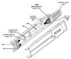
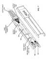
- FIG. 2Aillustrates a perspective view of an exemplary implementation of a splitter assembly 112 that includes an adapter housing, a splitter module guide and a splitter module consistent with the principles of the invention.
- Splitter assembly 112may include an adapter housing 202 , a splitter module guide 204 , a splitter module 206 , an output boot 208 and an output bundle 210 .
- Adapter housing 202may include any device, component and/or structure configured to house one or more fiber optic adapters that may be configured to mate with one or more fiber optic connectors. Adapter housing 202 may be adapted to mate with splitter module guide 204 and/or splitter module 206 . Adapter housing 202 and/or splitter module guide 204 may be dimensioned and arranged to operate with a panel therebetween. For example, adapter housing 202 may be located against a rear surface of a panel, or bulkhead faceplate, and splitter module guide 204 may be located against a front surface of the panel.
- Splitter module guide 204may include any device, component and/or structure configured to receive splitter module 206 .
- Splitter module guide 204may operate to align splitter module 206 for coupling with a fiber optic adapter associated with adapter housing 202 .
- Splitter module guide 204may slideably engage splitter module 206 to facilitate connecting splitter module 206 with adapter housing 202 .
- Splitter module guide 204may be configured and dimensioned to facilitate blind connection between splitter module 206 and a panel connection, such as an adapter associated with adapter housing 202 .
- “Blind connection” and/or “blind mateable”, as used herein,may refer to connecting/mating techniques, devices, components, and/or structures that facilitate mating a first connector with a second connector, or adapter, without requiring that an operator, such as a linesman, manipulating one of the connectors has to maintain a precise orientation of one connector/adapter with respect to the other connector/adapter.
- Splitter module 206may include any device, structure and/or component configured to split an incoming optical signal into two or more outgoing optical signals.
- Splitter module 206may include a splitting device configured to accept one or more incoming optical fibers and make signals on the incoming fibers available to two or more output fibers.
- the splitting devicemay be configured to facilitate bidirectional communication.
- Splitter module 206may be configured to optically mate with one or more adapters associated with adapter housing 202 when splitter module 206 is supported by splitter module guide 204 .
- Splitter module 206may be dimensioned and configured to facilitate installation and removal by a linesman using one hand. Implementations of splitter module 206 may be adapted to operate with various types of optical splitting devices that can have different shapes and/or form factors. Optical splitting devices that can be used with implementation of splitter module 206 may also be made by more than one manufacturer.
- Splitter module 206may be a passive device, an active device and/or a hybrid device having both passive and active capabilities.
- Output boot 208may include any device and/or structure configured to manage a bend radius associated with an optical fiber, provide strain relief to an optical fiber, provide mechanical and/or structural protection to an optical fiber, and/or facilitate maintaining an output fiber and/or group of output fibers, such as output bundle 210 , in a desired relationship with splitter module 206 and/or another device and/or structure.
- Output boot 208may be configured to operate with a number of individual fibers and/or with ribbons including a group of fibers.
- Output boot 208may be fabricated from rigid material and/or compliant/flexible material, such as plastic, rubber and/or composite.
- Output boot 208may include devices and/or structures to facilitate shaping, bending, arranging and/or configuring output bundle 210 according to pre-determined criteria and/or characteristics.
- Output boot 208may operate with adhesives to retain optical fibers in determined positions.
- Output bundle 210may include one or more individual fibers and/or one or more ribbons that may each include a number of fibers. Output bundle 210 may include an outer jacket to protect and retain individual fibers and/or ribbons in a determined arrangement and/or position. Output bundle 210 may include fiber output pigtails configured and dimensioned for routing in an enclosure. Output bundle 210 may include a transition member located along a group of output pigtails and configured to install in a transition region of an enclosure. Use of a transition member may facilitate circumferential routing of output pigtails within an enclosure.
- Splitter assembly 112may be adapted to operate with backplanes, chasses, enclosures, distribution fibers, etc. that are manufactured by entities other than an entity manufacturing a substantial portion of splitter assembly 112 .
- splitter assembly 112may operate with an adaptive backplane to interface with distribution fibers that were previously associated with a conventional splitter module employing, for example, a spliced input fiber.
- splitter assembly 112may be adapted to operate in substantially any number of fiber optic enclosures, such as in fiber distribution hubs. Therefore, disclosed implementations of splitter assembly 112 are not limited to the configurations and/or implementations described herein.
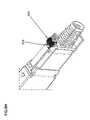
- FIG. 2Billustrates a perspective view of an exemplary implementation of a splitter assembly 112 that includes an adapter housing, a splitter module guide and an implementation of a splitter module that includes a latching device consistent with the principles of the invention.
- the implementation of FIG. 2Billustrates an alternative configuration of a splitter module 206 , denoted as splitter module 206 A, that may be configured with latching device 212 .
- Latching device 212may include any device, component, structure and/or technique that can be used to substantially retain splitter module 206 A in a determined relationship with respect to splitter module guide 204 and/or adapter housing 202 . Exemplary latching techniques are illustrated in conjunction with FIGS. 8A-K .
- the implementation of FIG. 2Bfurther illustrates features associated with an interior portion of splitter module guide 204 and/or adapter housing 202 .
- FIG. 3Aillustrates exemplary components that may be used in an exemplary implementation of an adapter housing 202 consistent with the principles of the invention.
- the implementation of FIG. 3Amay include adapter housing 202 , a first adapter assembly 304 , a second adapter assembly 306 , springs 308 A-D, screws 310 , a fastener channel 312 , and an alignment guide 314 .
- Adapter housing 202may provide a connectorized interface to splitter module 206 .
- Adapter housing 202may be fabricated from plastic, metal and/or composite using machining techniques and/or molding techniques.
- Adapter housing 202may include a first opening for receiving first adapter assembly 304 and/or a second opening for receiving second adapter assembly 306 .
- the first and second openingsmay each include one or more alignment guides 314 .
- Alignment guide 314may include any structure, device, and/or technique that may be adapted to guide and/or align first adapter assembly 304 and/or second adapter assembly 306 in respective openings of adapter housing 202 .
- Alignment guide 314may include a channel that may be configured to mate with a mating protuberance associated with first adapter assembly 304 and/or second adapter assembly 306 .
- Adapter housing 202may be configured, dimensioned and/or arranged to allow first adapter assembly 304 and/or second adapter assembly 306 to float within determined limits to facilitate blind mating with one or more fiber optic connectors, such as fiber optic connectors associated with optical splitter 206 and/or fiber connectors associated with distribution fiber 111 .
- Adapter housing 202may include a chamfer to facilitate blind-mating of first adapter assembly 304 and/or second adapter assembly 306 with one or more fiber optic connectors.
- Adapter housing 202may reduce and/or eliminate fiber loops associated with distribution fibers because distribution fibers may be terminated at a fixed length using a connector, such as a single coupling (SC) connector.
- SCsingle coupling
- First adapter assembly 304 and/or second adapter assembly 306may include any device, component, and/or structure configured to support a fiber optic adapter that may be configured to mate with a fiber optic connector. Implementations of first adapter assembly 304 and/or second adapter assembly 306 may be configured to accept an SC/APC connector, such as those that can be used in conjunction with 900 micrometer ( ⁇ m) fiber optic cables. First adapter assembly 304 and/or second adapter assembly 306 may be fabricated from plastic, metal and/or composite and may be machined and/or molded. Implementations of first adapter assembly 304 and second adapter assembly 306 may include an SC and/or SC-II adapter, respectively.
- LCliquid crystal
- MUMT-RJ
- MTferrule self (1.25 mm and/or 2.5 mm
- MT-multie.g., 4, 8, 12 fiber
- First adapter assembly 304may be installed in the first opening of adapter housing 202 in conjunction with springs 308 A and 308 B and second adapter assembly 306 may be installed in the second opening of adapter housing 202 in conjunction with springs 308 C and 308 D.
- Springs 308 A-Dmay include any device and/or structure configured to facilitate reliable and removable coupling of a fiber optic connector with first adapter assembly 304 and/or second adapter assembly 306 .
- Springs 308 A-Dmay exert a positive latching pressure and may operate to facilitate ejection of splitter module 206 when disengaged from an adapter and/or splitter module guide 204 .
- springs 308 A-Dmay operate to displace splitter module 206 away from adapter housing 202 when latching device 212 is disengaged from splitter module guide 204 .
- Screws 310may include any device and/or structure configured to releasably couple adapter housing 202 with another structure, such as splitter module guide 204 and/or a panel. Screws 310 may be adapted to fit through a fastener channel 312 associated with adapter housing 202 .
- FIG. 3Billustrates an assembled adapter housing consistent with the principles of the invention.
- first adapter assembly 304 and second adapter assembly 306are shown mounted in adapter housing 202 .
- the implementation of FIG. 3Bmay be releasably coupled to splitter module guide 204 using one or more screws 310 .
- FIG. 3Cillustrates an exemplary implementation of an assembled adapter assembly consistent with the principles of the invention.
- first adapter assembly 304is illustrated.
- FIG. 3Dillustrates a collection of exemplary components that may be used in an adapter assembly consistent with the principles of the invention.
- the adapter assembly of FIG. 3Dmay include an outer clip 320 , an adapter body 322 having an adapter face 324 and a split sleeve 326 , an interface member 328 having an inner clip face 330 , an upper retaining member 334 , a lower retaining member 336 and an inner clip 329 , an adapter flange 340 having a channel 342 and a flange face 344 .
- Outer clip 320may include any device and/or structure configured to receive at least a portion of a fiber optic connector. Outer clip 320 may be adapted to mate with adapter body 322 via a mounting surface. The mounting surface may be configured to fit inside adapter body 322 , against adapter body 322 , and/or over adapter body 322 .
- Adapter body 322may include any device and/or structure configured to facilitate coupling an optical signal to a destination. Adapter body 322 may be configured to mate with outer clip 320 on a first side and to mate with an interface member 328 via a second side. Adapter body 322 may include an adapter face 324 that may be configured to support split sleeve 326 . Split sleeve 326 may include any device and/or structure configured to mate with interface member 328 . Split sleeve 326 may include a protuberance that fits within an opening associated with interface member 328 . A surface of adapter face 324 may be adapted to abut a surface of inner clip face 330 when an adapter assembly is assembled.
- Interface member 328may include any device and/or structure configured to facilitate coupling an optical signal to a destination.
- Interface member 328may include an inner clip 329 that may include any device and/or structure configured to engage split sleeve 326 .
- Interface member 328may include an inner clip face 330 that may include an opening operatively associated with inner clip 329 , a first face for mating against a surface of adapter face 324 and/or a second face for supporting an upper retaining member 334 and/or a lower retaining member 336 .
- Upper retaining member 334 and/or lower retaining member 336may include any device and/or structure configured to releaseably engage interface member 328 with adapter flange 340 .
- Upper retaining member 334 and lower retaining member 336may cooperatively operate to retain interface member 328 and adapter flange 340 in an engaged relationship by exerting pressure against an inner surface of adapter flange 340 .
- Upper retaining member 334 and/or lower retaining member 336may be dimensioned and configured with latching surfaces, such as hooks, ridges, channels, keys, etc., to facilitate engagement with an inner surface of adapter flange 340 .
- Adapter flange 340may include any device and/or structure configured to receive an interface member 328 .
- Adapter flange 340may include a housing that has an inner volume having a first opening to receive at least a portion of interface member 328 and/or a second opening that may be made available to an inner volume associated with splitter module guide 204 and/or to a connector associated with splitter module 206 .
- Adapter flange 340may include a flange face 344 that may be adapted to abut a surface of adapter face 324 and/or inner clip face 330 when interface member 328 is engaged with adapter flange 340 .
- Adapter flange 340may include one or more channels 342 that may be adapted to facilitate aligning components associated with an adapter assembly and/or to facilitate aligning adapter flange 340 with splitter module guide 204 and/or splitter module 206 .
- An inner surface of adapter flange 340may be configured and dimensioned to facilitate engagement with upper retaining member 334 and/or lower retaining member 336 .
- FIG. 4Aillustrates an exemplary splitter module guide 204 consistent with the principles of the invention.
- Splitter module guide 204may include a housing having an exterior surface that may be configured to form an inner volume.
- the inner volumemay be adapted to accept splitter module 206 via a first end and make splitter module 206 available to adapter housing 202 via a second end.
- the inner volumemay include a first guide rib 402 and/or a second guide rib 404 .
- First guide rib 402 and/or second guide rib 404may include any device and/or structure configured to align and/or guide optical splitter module 206 as it is received via the first end of splitter module guide 204 .
- First guide rib 402 and/or second guide rib 404may run substantially the length of splitter module guide 204 and/or may span a portion of the length of splitter module guide 204 .
- Splitter module guide 204may include one or more fastener channels 406 .
- Fastener channel 406may be configured to receive a fastening device, such as a screw, to retain splitter module guide 204 in a determined relationship with respect to another structure, such as adapter housing 202 and/or a panel surface.
- FIG. 4Billustrates a collection of exemplary components that may be used in an exemplary implementation of splitter module guide 204 consistent with the principles of the invention.
- Splitter module guide 204may include door 408 , channel 410 , spring 412 , pin 414 , first opening 416 , and second opening 418 .
- a first end of splitter module guide 204may be configured with door 408 to prevent dirt and debris from entering the inner volume of splitter module guide 204 when splitter module 206 is not present.
- Door 408may include any device and/or structure configured to discourage the accumulation of debris within the inner volume of splitter module guide 204 .
- Door 408may function as a dust cover that does not have to be removed from splitter module guide 204 .
- Door 408may be configured to operate as a safety device by preventing optical radiation from exiting splitter module guide 204 when optical splitter 206 is not engaged therewith.
- a distribution fiber 111may provide high intensity radiation to an adapter associated with adapter housing 202 .
- Adapter housing 202may in turn make the radiation available to the second end of splitter module guide 204 . If splitter module 206 is not present, radiation may exit via the first end of splitter module guide 204 if door 408 is not in a closed position.
- Door 408may be pivotally supported on splitter module guide 204 via pin 414 .
- Pin 414may include any device and/or structure configured to allow rotation of door 408 about a pivoting location or axis. Pin 414 may pass through a first opening 416 , through channel 410 and/or through second opening 418 . Pin 414 may be retained in contact with first opening 416 and/or second opening 418 when installed in splitter module guide 204 . Pin 414 may operate in conjunction with spring 412 to manipulate door 408 into a first position, such as a closed position, that may impede access to the inner volume of splitter module guide 204 when optical splitter module 206 is not present. Door 408 may prevent optical radiation associated with distribution fiber 111 from exiting splitter module guide 204 when door 408 is in the first position.
- Door 408may be configured to move to a second position, such as an open position, when splitter module 206 is engaged with splitter module guide 204 .
- Door 408may be configured so that its surfaces remain substantially free of debris when splitter module 206 is engaged with splitter module guide 204 .
- Optical radiation associated with distribution fiber 111may be made available to splitter module 206 when door 408 is in the second position.
- door 408may return to the first position in cooperation with forces provided by spring 412 .
- Spring 412may be configured to apply sufficient force so as to move door 408 into the closed position without allowing any radiation to reach an operator, such as a linesman.
- Implementationsmay employ door 408 having a pivoting attachment point that is associated with a side and/or the top of splitter module guide 204 instead of with the bottom of splitter module guide 204 as shown in FIG. 4B .
- Door 408may also be implemented in sections that may be operatively coupled together and/or operatively associated with each other. For example, door 408 may be implemented via two smaller doors operating together to substantially block the first end of splitter module guide 204 when in a closed position. Door 408 may be replaced by, or may operate with, a removable dust cover if desired.
- FIG. 5Aillustrates a side view of an exemplary implementation of splitter module 206 consistent with the principles of the invention.
- Splitter module 206 and/or 206 Amay include an upper shell 502 , a lower shell 508 ( FIG. 5B ), a first connector 504 and a second connector 506 .
- Upper shell 502 and/or lower shell 508may include any device and/or structure configured to at least partially enclose an optical splitting device.
- Upper shell 502 and/or lower shell 508may be fabricated from plastic, metal and/or composite and may be adapted to releasably engage each other.
- Splitter module 206may have an exemplary length on the order of 5.5 inches, an exemplary width on the order of 0.5 inches, and an exemplary height on the order of 1 inch. Another implementation of splitter module 206 may be implemented with a length of 5.6 inches, a width of 0.65 inches and a height of 1.1 inches and having a volume on the order of 4 cu-in. Implementations of splitter module 206 may take other forms and/or sizes without departing from the spirit of the invention.
- FIG. 5Billustrates a top view of an exemplary implementation of splitter module 206 consistent with the principles of the invention.
- Implementationsmay employ a splitter module shell having a standard size that may be adapted to accommodate a number of optical splitting devices made by a number of manufacturers. The use of a standard sized shell may reduce the number of inventoried parts required to outfit enclosures with optical splitting capabilities.
- FIG. 5Cillustrates an end view showing the inputs to an exemplary implementation of splitter module 206 consistent with the principles of the invention.
- Implementations of splitter module 206may include SC, SC-II, LC, MU, MT-RJ, MT or ferrule self (1.25 mm and/or 2.5 mm), and/or MT-multi (e.g., 4, 8, 12 fiber) connectors.
- MT-multie.g., 4, 8, 12 fiber
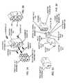
- FIG. 6Aillustrates a perspective view of an exemplary implementation of a splitter module 206 consistent with the principles of the invention.
- the implementation of FIG. 6Amay include a first tab 601 , a lateral guide channel 602 , a second tab 603 , and/or an upper guide channel 604 .
- Upper tab 601 and lower tab 603may be configured and arranged to protect first connector 504 and/or second connector 506 from contact with other structures.
- First tab 601 and second tab 603may be formed from a portion of upper shell 502 and/or lower shell 508 .
- Lateral guide channel 602 and/or upper guide channel 604may be configured and dimensioned to facilitate alignment of optical splitter module 206 with first guide rib 402 ( FIG. 4A ) and/or second guide rib 404 of splitter module guide 204 .
- Lateral guide channel 602 and/or upper guide channel 604may be configured and dimensioned to operate as keys to prevent, for example, a splitter module 206 having two connectors from being mated with an adapter housing 202 having a single connector, and vice versa, and/or the mating of splitter module 206 having a first type of connector from being mated with an incompatible adapter associated with adapter housing 202 .
- Splitter module guide 204may operate with lateral guide channel 602 and/or upper guide channel 604 to implement keying arrangements and/or techniques.
- Alternative implementationsmay replace lateral guide channel 602 and/or upper guide channel 604 with other devices, structures and/or components to facilitate keying and/or alignment of splitter module 206 within splitter module guide 204 to facilitate blind mating and interconnect compatibility between adapter housing 202 and splitter module 206 without departing from the spirit of the invention.
- FIG. 6Billustrates components that may be used in an exemplary implementation of splitter module 206 consistent with the principles of the invention.
- the implementation of FIG. 6Bmay include an integrated optical splitter 606 having an input side 608 and an output side 610 , an input support 612 , and splitter supports 614 , 615 , 616 .
- Integrated optical splitter 606may include any device and/or component configured to split an incoming optical signal into two or more outgoing optical signals.
- Integrated optical splitter 606may have an input side 608 that is associated with one or more incoming fibers.
- Integrated optical splitter 606may accept a single incoming fiber and/or may accept multiple incoming fibers.
- the incoming fibermay be spliced into substantially any number of outgoing fibers using techniques known in the art. For example, an incoming fiber may be spliced via fusion and/or mechanical techniques to join the incoming fiber to two or more outgoing fibers.
- An implementation of integrated optical splitter 606may include an optical splitter manufactured by a number of companies, such as NH Spring Co, LTD.
- an NH Spring Co, LTD model DW-PKG-32-0282XR1 1:32 splittermay be used and/or a model DW-PKG-16-0281XR1 1:16 splitter may be used without departing from the spirit of the invention.
- Other types of optical splitting devicesmay also be used alone or in combination without departing from the spirit of the invention.
- Integrated optical splitter 606may include an output side 610 adapted to make two or more optical fibers available to a destination. Implementations of integrated optical splitter 606 may have output side 610 adapted to make output fibers available to a destination using one or more fiber ribbons. For example, output side 610 may make 16 outputs available via two ribbons each having eight fibers associated therewith, and/or output side 610 may make 32 outputs available via four ribbons each having eight fibers associated therewith.
- Integrated optical splitter 606may be implemented in a 1 by X, 2 by X, or Y by X configuration where X and Y may be substantially any integer. A 1 by X implementation may accept one input fiber, a 2 by X implementation may accept two input fibers, and a Y by X implementation may accept Y input fibers.
- Upper shell 502 and/or lower shell 508may operate as a housing that includes supporting structures adapted to maintain incoming fibers, integrated optical splitter 606 , and outgoing fibers in determined positions relative to an inner volume formed by upper shell 502 and/or lower shell 508 .
- an input support 612may be provided to support one or more incoming fibers in a determined position.
- Upper shell 502 and/or lower shell 508may include oppositely mounted input supports 612 so that an input fiber is captively retained.
- Splitter supports 614 , 615 and 616may be provided to support integrated optical splitter 606 in a determined position relative to upper shell 502 and/or lower shell 508 .
- Upper shell 502 and lower shell 508may include oppositely mounted splitter supports 614 , 615 and 616 to prevent integrated optical splitter 606 from moving relative to upper shell 502 and/or lower shell 508 .
- Upper shell 502 and/or lower shell 508may include output supports (not shown) to support output fibers if desired.
- Implementations of upper shell 502 and/or lower shell 508may be dimensioned and configured to operate with substantially any number of integrated optical splitters 606 .
- splitter supports 614 , 615 and 616may be configured to operate with particular models and/or quantities of integrated optical splitter 606 .
- upper shell 502 and/or lower shell 508may be adapted to use removable splitter supports 614 , 615 and 616 to facilitate the use of more than one type of integrated optical splitter 606 .
- integrated optical splitter 606may be attached to upper shell 502 and/or lower shell 508 via adhesive and/or other bonding techniques if desired.
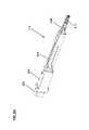
- FIG. 7illustrates an exemplary configuration of components that may be used in an exemplary implementation of splitter module 206 .
- the implementation of FIG. 7may include a first input fiber 702 , a second input fiber 704 , an output ribbon 706 , an output fiber 708 , a fiber management guide 710 , and output boot 208 .
- First and second input fiber 702 , 704may include any type of optical fiber capable of carrying an optical signal.
- First input fiber 702may be coupled to first connector 504 and second input fiber 704 may be coupled to second connector 506 .
- Implementationsmay facilitate connection of first and second input fiber 702 , 704 to integrated optical splitter 606 without the use of fiber loops within splitter module 206 .
- Output ribbon 706may include two or more groups of output fibers 708 that may be used to convey output signals to one or more destinations.
- Output fiber 708may pass through a fiber management guide 710 en route to a destination, such as a subscriber termination in an enclosure.
- Output ribbons 706may be replaced by individual output fibers without departing from the spirit of the invention.
- Fiber management guide 710may include any device and/or structure configured to maintain one or more optical fibers and/or ribbons in a desired arrangement. Fiber management guide 710 may incorporate overtubes to guide output fibers through output boot 208 . Overtubes may be affixed to fiber management guide 710 and output fibers may be run through the overtubes. Overtubes may be affixed to fiber management guide 710 via adhesive and/or other bonding techniques. Fiber management guide 710 may operate in conjunction with output boot 208 to guide output fibers to a destination. Output fiber 708 may be terminated with a connector adapted to mate with a subscriber termination associated with a subscriber premises. Output boot 208 may operate as a single strain relief device for substantially all output fibers passing through fiber management guide 710 .
- FIGS. 8A and 8Billustrate exemplary latching devices that may be used for coupling splitter module 206 to an exemplary implementation of splitter module guide 204 consistent with the principles of the invention.
- the implementation of FIG. 8Amay include a pivoting retaining lever 802 .
- Pivoting retaining lever 802may be adapted to engage a portion of optical splitter module 206 when in a closed position.
- pivoting retaining lever 802may be adapted to engage a portion of splitter module guide 204 .
- Implementationsmay employ a single pivoting retaining lever 802 and/or multiple pivoting retaining levers. Pivoting retaining lever 802 may be configured and dimensioned so that a linesman may operate pivoting retaining lever 802 with one hand.
- Splitter module 206 and/or splitter module guide 204may be configured with devices and/or structures to facilitate engagement with a latching device and/or to provide a linesman with an audible, tangible, and/or visual indication of engagement and/or disengagement of the latching device with splitter module 206 and/or splitter module guide 204 .
- FIG. 8Billustrates a retaining device 804 that may include a latching member 806 and a tensioning member 808 .
- Latching member 806may include any device and/or structure configured to engage tensioning member 808 when in a closed position.
- Tensioning member 808may include any device and/or structure configured to provide a retaining force when engaged by latching member 806 .
- Tensioning member 808may be fabricated from spring steel, composite, rubber, plastic, and the like.
- Tensioning member 808may be configured with a hook on a distal end to engage latching member 806 .
- Latching member 806may operate to exert a force on tensioning member 808 when in a closed position.
- Retaining device 804may be configured and dimensioned so that a linesman may manipulate retaining device 804 with one hand.
- FIGS. 8C and 8Dillustrate an exemplary retaining device that may be used for coupling splitter module 206 A to an exemplary implementation of splitter module guide 204 consistent with the principles of the invention.
- Splitter module 206 Amay be configured to include an upper coupling member 810 having an upper coupling surface 814 , and a lower coupling member 812 having a lower coupling surface 816 .
- Splitter module guide 204may include an upper mating surface 818 and a lower mating surface 820 .
- Upper coupling member 810 and/or lower coupling member 812may include any device and/or structure configured to retain splitter module 206 A in a determined position relative to splitter module guide 204 and/or adapter housing 202 .
- Upper coupling member 810 and/or lower coupling member 812may be fabricated from metal, plastic and/or composite and may be moveably coupled to splitter module 206 A in a manner allowing upper coupling member 810 and/or lower coupling member 812 to exert a retaining force on upper mating surface 818 and/or lower mating surface 820 .
- Upper coupling member 810may include an upper coupling surface 814 that may be configured and dimensioned to mate with upper mating surface 818 .
- Lower coupling member 812may include a lower coupling surface 816 that may be configured and dimensioned to mate with lower mating surface 820 . Applying a force on upper distal portion 822 and/or lower distal portion 824 may cause upper coupling surface 814 and/or lower coupling surface 816 to be displaced outward (i.e., away from optical splitter module 206 A) to facilitate engagement and/or disengagement of splitter module 206 A with splitter module guide 204 and/or adapter housing 202 .
- FIG. 8Dillustrates splitter module 206 A in a mated, or engaged, position with respect to splitter module guide 204 and/or adapter housing 202 .
- FIGS. 8E and 8Fillustrate an exemplary retaining device that may be used to couple splitter module 206 B to an exemplary implementation of splitter module guide 204 consistent with the principles of the invention.
- the implementation illustrated in FIG. 8Emay include an upper coupling member 810 A, a lower coupling member 812 A, an upper coupling surface 814 A, a lower coupling surface 816 A, an upper mating surface 818 A, a lower mating surface 820 A, an upper distal portion 822 A, and a lower distal portion 824 A.
- Upper coupling member 810 A, lower coupling member 812 A, upper coupling surface 814 A, lower coupling surface 816 A, upper mating surface 818 A, lower mating surface 820 A, upper distal portion 822 A, and lower distal portion 824 Amay be similar to their counterparts discussed in connection with FIG. 8C .
- Upper coupling surface 814 A and lower coupling surface 816 Amay be configured to move into upper mating surface 818 A and lower mating surface 820 A, respectively.
- Upper mating surface 818 A and lower mating surface 820 Amay include any contoured surface configured to receive upper coupling surface 814 A or lower coupling surface 816 A.
- upper mating surface 818 A and lower mating surface 820 Amay each include a channel adapted to receive coupling surfaces associated with splitter module 206 B.
- Upper mating surface 818 A and lower mating surface 820 Amay be tapered to facilitate receipt of a coupling surface.
- Upper coupling surface 814 A and lower coupling surface 816 Amay be angled and/or tapered to facilitate mating with upper mating surface 818 A and lower mating surface 820 A, respectively.
- Upper coupling surface 814 A and lower coupling surface 816 Amay exert pressure toward a center line of splitter module guide 204 in cooperation with upper coupling member 810 A and lower coupling member 812 A, respectively. Exerted pressure may operate to keep the mating surfaces and coupling surfaces in a determined relationship.
- FIG. 8Fillustrates a perspective view of splitter module 206 B that shows upper coupling surface 814 A and lower mating surface 816 A in more detail.
- FIG. 8Gillustrates exemplary alignment aides that can be used to facilitate alignment of splitter module 206 B with splitter module guide 204 consistent with the principles of the invention.
- First alignment aide 828 and second alignment aide 830may include any device, structure and/or technique for aligning a first object with a second object.
- a top surface of splitter module guide 204may include a raised surface having a shape of a triangle, where a corner of the triangle faces in a direction that corresponds to a direction in which splitter module 206 B is displaced when engaging splitter module guide 204 .
- the raised surfacemay be first alignment aide 828 .
- Splitter module 206 Bmay include a raised surface having a shape similar to first alignment aide 828 .
- the raised surface on splitter module 206 Bmay be a second alignment aide 830 .
- Second alignment aide 830may be arranged on a top surface of splitter module 206 B so that a corner of the triangle faces in a direction that corresponds to a direction in which splitter module 206 B is displaced when engaging splitter module guide 204 .
- First alignment aide 828 and second alignment aide 830may include textured, colored, and/or shaped devices and/or structures that can be used to facilitate the alignment of one object with another object.
- First alignment aide 828 and second alignment aide 830may include passive devices, such as textured surfaces, and/or active devices, such as light emitting diodes (LEDs).
- First alignment aide 828 and second alignment aide 830may operate alone or with upper and/or lower coupling surfaces 814 A and 814 B and/or with upper and/or lower mating surfaces 818 A and 818 B.
- FIGS. 8H-8Killustrate various views of an exemplary lock device that can be used to retain splitter module 206 B in a determined relationship with splitter module guide 204 consistent with the principles of the invention.
- a region proximate to upper distal portion 822 A and/or lower distal portion 824 Amay be equipped with an unlocked indicator 832 and/or a lock device 834 ( FIG. 8H ).
- Unlocked indicator 832may include any device, structure and/or technique adapted to indicate a status of lock device 834 .
- Unlocked indicator 832may include passive and/or active devices, structures and/or techniques.
- Lock device 834may include any device and/or structure that can be configured to retain a coupling surface in a determined relationship with a mating surface.
- lock device 834may operate alone or with other devices and/or structures to retain upper coupling surface 814 A in a determined relationship, such as a mated relationship, with upper mating surface 818 A.
- Lock device 834may operate to discourage disengagement of upper coupling surface 814 A from upper mating surface 818 A.
- Lock device 834may be fabricated from plastic, composite, rubber, metal and/or other suitable materials.
- Lock device 834may be color coded to facilitate identification of splitter module 206 B.
- a lock device 834may have a first color to identify a splitter module having one optical connector and another lock device 834 may have a second color to identify a splitter module having two optical connectors.
- Lock device 834may operate with a lock support member 836 ( FIG. 81 ) to retain upper coupling surface 814 A in a determined position.
- lock device 834may have a lip or other protuberance that is configured to be supported by lock support member 836 when in a locked position.
- Lock device 834may be moved into a locked position by sliding lock device 834 in a locking direction 838 .
- Lock device 834may be moved into an unlocked position by, for example, sliding lock device 834 in a direction opposite to locking direction 838 .
- Lock device 834may operate in conjunction with a locked indicator ( FIG. 8J ).
- Locked indicator 840may include any device, structure and/or technique for identifying a locked position of lock device 834 .
- Locked indicator 840may be textured and/or colored and may operate in cooperation with unlocked indicator 832 .
- unlocked indicator 832may have a first color, such as green
- locked indicator 840may have a second color, such as red.
- FIG. 8Killustrates a side view of lock device 834 in a locked position in conjunction with lock support member 836 .
- the implementations illustrated in FIGS. 8A-8Kmay be configured to be operated via a single hand and may be configured to provide a visual and/or tactile indication of a locked and/or unlocked status. For example, sliding lock device 834 into a locked position may expose locked indicator 840 and/or may produce an audible click, or other sound.
- FIG. 9Aillustrates an exemplary arrangement of splitter assemblies 112 supported on a shelf consistent with the principles of the invention.
- the implementation of FIG. 9Amay include an upper shelf 902 and one or more distribution fibers 901 .
- Upper shelf 902may include any device and/or structure configured to support one or more splitter assemblies 112 in a determined position.
- Upper shelf 902may include a splitter mounting panel 916 ( FIG. 9B ) to facilitate the mounting and operation of splitter assemblies 112 .
- Splitter mounting panel 916may include a substantially flat surface arranged at an angle with respect to upper shelf 902 .
- splitter mounting panel 916may be mounted substantially perpendicular to upper shelf 902 .
- FIG. 9Billustrates an exemplary arrangement of splitter module shelves in an enclosure consistent with the principles of the invention.
- Frame 900may include incoming fibers 901 , upper shelf 902 , middle shelf 904 , lower shelf 906 , first side 908 , second side 910 , base 912 , fiber guide 914 , fiber radius guide 915 and splitter mounting panel 916 .
- Middle shelf 904 and/or lower shelf 906may include any device and/or structure configured to support a splitter assembly 112 .
- Upper shelf 902 , middle shelf 904 and lower shelf 906may include one or more fiber guides 914 , fiber radius guides 915 and/or splitter mounting panels 916 .
- First side 908 , second side 910 and base 912may include any device and/or structure that can be configured and arranged to support upper shelf 902 , middle shelf 904 and/or lower shelf 906 as an assembly.
- First side 908 , second side 910 and base 912may be fabricated from metal, plastic, composite and/or wood and may be coupled together using fasteners, welding techniques, and/or adhesive-based bonding techniques.
- Upper shelf 902 , middle shelf 904 , and/or lower shelf 906may include one or more fiber guides 914 that may be configured to maintain optical fibers in a determined position.
- upper shelf 902may include fiber radius guide 915 that may be configured to maintain a determined bend radius for one or more optical fibers associated with splitter assemblies 112 .
- fiber radius guide 915may be configured to maintain a specified minimum bend radius, such as a manufacturer and/or industry specified minimum bend radius, for output fibers exiting splitter module 206 .
- Splitter mounting panel 916may be configured to support multiple splitter assemblies 112 in a determined arrangement.
- Splitter mounting panel 916may be configured to reside between adapter housing 202 and splitter module guide 204 such that adapter housing 202 abuts a rear surface of splitter mounting panel 916 and splitter module guide 204 abuts a front surface of splitter mounting panel 916 .
- splitter mounting panel 916may be arranged at an angle, such as approximately ninety degrees, with respect to upper shelf 902 , middle shelf 904 and/or lower shelf 906 .
- Splitter mounting panel 916may operate alone or in combination with other devices and/or structures as an adaptable backplane to facilitate mounting disclosed implementations into enclosures manufactured by entities other than an entity that manufactured splitter module 206 , splitter module 204 and/or adapter housing 202 .
- implementations of splitter assemblies 112may be adapted to mount into a portion of an enclosure configured to handle conventional optical splitters having input pigtails that were spliced to distribution fiber 111 and that are manufactured by an entity other than the manufacturer of implementations disclosed herein.
- a spliced distribution fibermay be terminated with a connector that can be coupled to an adapter associated with adapter housing 202 .
- Adapter housing 202may be on a rear face of splitter mounting panel 916 and splitter module guide 204 may be mounted to a front face of splitter mounting panel 916 .
- Implementations of splitter module 206may be used with the distribution fiber to convey optical signals to subscribers.
- Frame 900may be mounted on a swing frame to facilitate pivoting the entire assembly around a pivoting location to provide access to rear portions of the assembly.
- a swing framemay allow a linesman working at the front of an enclosure to gain access to distribution fiber 901 without requiring that the linesman operate in an awkward manner, such as by not being able to see a connector associated with distribution fiber 901 .
- Frame 900may employ a latching device to maintain the frame in a first position, such as a closed position, and/or a second position, such as an open position.
- Alternative implementationsmay employ swing frames on portions of frame 900 .
- upper shelf 902may be mounted on a swing frame such that upper shelf 902 may be swung from a first position to a second position.
- additional slackmay be provided in distribution fiber 901 and/or output pigtails so that optical fibers are not stretched, pinched, or bent in a manner that violates a recommended minimum bend radius.
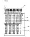
- FIG. 9Cillustrates an exemplary arrangement of splitter assemblies 112 , subscriber terminations, and parking adapters consistent with the principles of the invention.
- Frame 900may include an adapter mounting area 930 , a subscriber termination area 932 having a subscriber termination module 936 , and a parking area 934 having a parking module 938 .
- Frame 900may be sized to fit into an equipment enclosure, such as a fiber distribution hub.
- Adapter mounting area 930may include any device and/or structure configured to support one or more splitter assemblies 112 . Implementations may employ an adapter mounting area 930 that is configured to support upper shelf 902 , middle shelf 904 and/or lower shelf 906 . Adapter mounting area 930 may be configured on a swing frame that lets adapter mounting area 930 swing independently from other portions of frame 900 . In other implementations, adapter mounting area 930 may be configured to swing in conjunction with other portions of frame 900 .
- Subscriber termination area 932may include any device and/or structure configured to support one or more subscriber termination modules 936 . Subscriber termination area 932 may operate to make optical signals available to subscribers via a subscriber port coupled to a drop fiber 116 ( FIG. 1 ) associated with ONT 114 . ONT 114 may be associated with a subscriber. Subscriber termination module 936 may include any device and/or structure configured to receive an optical connector and/or adapter associated with an optical signal intended for a destination.
- Parking area 934may include any device and/or structure configured to support one or more parking modules 938 .
- Parking module 938may include any device and/or structure configured to facilitate parking of connectors and/or adapters associated with optical fibers.
- parking module 938may include a group of receptacles and/or adapters configured and dimensioned to receive an optical connector and/or adapter associated with an output pigtail.
- Splitter assemblies 112may be configured with output pigtails that may be terminated with connectors and/or adapters, such as SC/APC, SC/UPC, ST, FC, and LC.
- the output pigtailsmay be of varying lengths and/or may be of the same length.
- Parking area 934may also be adapted to receive an end of splitter module 206 having connectors associated therewith to protect the connectors from debris.
- Output pigtailsmay be routed within an enclosure so that pigtail connectors can be plugged into a receptacle and/or adapter associated with parking module 938 when not coupled to a subscriber termination port.
- Employing parking module 938may prevent dirt and debris from accumulating on output pigtail connectors and/or adapters when not in use.
- the output pigtail connectorWhen a subscriber is connected to an output pigtail, the output pigtail connector may be removed from a parking location and plugged into the appropriate subscriber termination to make an optical signal available to ONT 114 .
- Output pigtailsmay be dimensioned so as to facilitate circumferential routing within an enclosure. Circumferential routing may prevent tangling of pigtails as they are removed from a parked location and coupled to a subscriber termination by providing an organized routing scheme for manipulating pigtails within an enclosure.
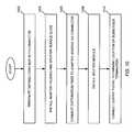
- FIG. 10illustrates an exemplary method for coupling distribution fiber 111 to a splitter assembly 112 consistent with the principles of the invention.
- a distribution fiber 111may be terminated with a connector (act 1002 ).
- the connectormay be configured to mate with an adapter associated with an adapter housing 202 .
- Adapter housing 202 and splitter module guide 204may be installed in an enclosure that includes distribution fiber 111 (act 1004 ).
- Distribution fiber 111may be connected to a first end of an adapter associated with adapter housing 202 via the connector attached to distribution fiber 111 in act 1002 (act 1006 ).
- An optical signalhere referred to as a distribution signal, may be provided to the first end of the adapter when the distribution fiber connector is coupled to the adapter.
- Splitter module guide 204may be installed proximate to adapter housing 202 .
- adapter housing 202may be installed on a rear surface of a bulkhead panel and splitter module guide 204 may be installed on a front surface in a manner that exposes adapters in adapter housing 202 to splitter module guide 204 .
- An optical splitter module 206may be installed in splitter module guide 204 by a linesman (act 1008 ). The distribution signal may be provided to one or more output pigtails when optical splitter module 206 is coupled to a second end of the adapter associated with the adapter housing 202 in cooperation with splitter module guide 204 .
- An output pigtailmay be connected to a parking location and/or a subscriber termination via a connector associated with the output pigtail (act 1010 ). If the output pigtail is connected to a subscriber termination, a subscriber may participate in bidirectional communication with OLT 102 via the distribution signal.
- components used in splitter assembly 112may be fabricated from polycarbonate and/or ABS via machining, injection molding, etc.
- active componentscan be used in conjunction with the passive components described herein.
- Electronic devices, such as computers and radio frequency identification (RFID) tagsmay be used to facilitate automated testing and/or inventorying of devices used within enclosures.
- RFIDradio frequency identification
- sequence of events associated with the methods described hereincan be performed in orders other than those illustrated.
- additional eventscan be added, or removed, depending on specific deployments, applications, and the needs of users, linesmen, and/or service providers. Further, disclosed implementations may not be limited to any specific combination of hardware circuitry and/or software.
Landscapes
- Physics & Mathematics (AREA)
- General Physics & Mathematics (AREA)
- Optics & Photonics (AREA)
- Light Guides In General And Applications Therefor (AREA)
- Mechanical Coupling Of Light Guides (AREA)
- Optical Couplings Of Light Guides (AREA)
Abstract
Description
Claims (13)
Priority Applications (5)
| Application Number | Priority Date | Filing Date | Title |
|---|---|---|---|
| US11/213,772US7636507B2 (en) | 2005-06-17 | 2005-08-30 | Compact blind mateable optical splitter |
| CN2006800298156ACN101243344B (en) | 2005-06-17 | 2006-06-15 | Compact blind matching optical splitter |
| PCT/US2006/023304WO2006138460A1 (en) | 2005-06-17 | 2006-06-15 | Compact blind mateable optical splitter |
| EP06784927AEP1896887A1 (en) | 2005-06-17 | 2006-06-15 | Compact blind mateable optical splitter |
| US12/645,086US8086085B2 (en) | 2005-06-17 | 2009-12-22 | Compact blind mateable optical splitter |
Applications Claiming Priority (2)
| Application Number | Priority Date | Filing Date | Title |
|---|---|---|---|
| US69122805P | 2005-06-17 | 2005-06-17 | |
| US11/213,772US7636507B2 (en) | 2005-06-17 | 2005-08-30 | Compact blind mateable optical splitter |
Related Child Applications (1)
| Application Number | Title | Priority Date | Filing Date |
|---|---|---|---|
| US12/645,086ContinuationUS8086085B2 (en) | 2005-06-17 | 2009-12-22 | Compact blind mateable optical splitter |
Publications (2)
| Publication Number | Publication Date |
|---|---|
| US20060285807A1 US20060285807A1 (en) | 2006-12-21 |
| US7636507B2true US7636507B2 (en) | 2009-12-22 |
Family
ID=37102536
Family Applications (2)
| Application Number | Title | Priority Date | Filing Date |
|---|---|---|---|
| US11/213,772Active2026-02-05US7636507B2 (en) | 2005-06-17 | 2005-08-30 | Compact blind mateable optical splitter |
| US12/645,086Expired - Fee RelatedUS8086085B2 (en) | 2005-06-17 | 2009-12-22 | Compact blind mateable optical splitter |
Family Applications After (1)
| Application Number | Title | Priority Date | Filing Date |
|---|---|---|---|
| US12/645,086Expired - Fee RelatedUS8086085B2 (en) | 2005-06-17 | 2009-12-22 | Compact blind mateable optical splitter |
Country Status (4)
| Country | Link |
|---|---|
| US (2) | US7636507B2 (en) |
| EP (1) | EP1896887A1 (en) |
| CN (1) | CN101243344B (en) |
| WO (1) | WO2006138460A1 (en) |
Cited By (45)
| Publication number | Priority date | Publication date | Assignee | Title |
|---|---|---|---|---|
| US20100129041A1 (en)* | 2008-11-25 | 2010-05-27 | Fujitsu Limited | Attachment part and electronic apparatus |
| US20100129030A1 (en)* | 2008-11-24 | 2010-05-27 | Giraud William J | Universal Optical Splitter Modules and Related Mounting Brackets, Assemblies and Methods |
| US20100142888A1 (en)* | 2008-12-10 | 2010-06-10 | Verizon Corporate Resources Group Llc | Compact fiber distribution hub |
| US20110002591A1 (en)* | 2005-06-17 | 2011-01-06 | Adc Telecommunications, Inc. | Compact Blind Mateable Optical Splitter |
| US8498511B2 (en) | 2005-08-30 | 2013-07-30 | Adc Telecommunications, Inc. | Fiber distribution hub with modular termination blocks |
| US20140193147A1 (en)* | 2012-10-29 | 2014-07-10 | Adc Telecommunications, Inc. | System for Testing Passive Optical Lines |
| US8792767B2 (en) | 2010-04-16 | 2014-07-29 | Ccs Technology, Inc. | Distribution device |
| US8798427B2 (en) | 2007-09-05 | 2014-08-05 | Corning Cable Systems Llc | Fiber optic terminal assembly |
| US8879882B2 (en) | 2008-10-27 | 2014-11-04 | Corning Cable Systems Llc | Variably configurable and modular local convergence point |
| US8909019B2 (en) | 2012-10-11 | 2014-12-09 | Ccs Technology, Inc. | System comprising a plurality of distribution devices and distribution device |
| US8953922B1 (en)* | 2011-07-26 | 2015-02-10 | Juniper Networks, Inc. | Fiber ribbon strain relief clamp |
| US9004778B2 (en) | 2012-06-29 | 2015-04-14 | Corning Cable Systems Llc | Indexable optical fiber connectors and optical fiber connector arrays |
| US9049500B2 (en) | 2012-08-31 | 2015-06-02 | Corning Cable Systems Llc | Fiber optic terminals, systems, and methods for network service management |
| US20150205064A1 (en)* | 2012-07-09 | 2015-07-23 | Tyco Electronics Raychem Bvba | Cable management system including splitter/filter tray |
| US9182563B2 (en) | 2011-03-31 | 2015-11-10 | Adc Telecommunications, Inc. | Adapter plate for fiber optic module |
| US9219546B2 (en) | 2011-12-12 | 2015-12-22 | Corning Optical Communications LLC | Extremely high frequency (EHF) distributed antenna systems, and related components and methods |
| US9239442B2 (en) | 2010-04-27 | 2016-01-19 | Adc Communications (Shanghai) Co., Ltd. | Fiber optic module and chassis |
| US9301030B2 (en) | 2013-11-11 | 2016-03-29 | Commscope Technologies Llc | Telecommunications module |
| US9323020B2 (en) | 2008-10-09 | 2016-04-26 | Corning Cable Systems (Shanghai) Co. Ltd | Fiber optic terminal having adapter panel supporting both input and output fibers from an optical splitter |
| US9395509B2 (en) | 2014-06-23 | 2016-07-19 | Commscope Technologies Llc | Fiber cable fan-out assembly and method |
| US9417401B2 (en) | 2011-09-06 | 2016-08-16 | Commscope Technologies Llc | Adapter for fiber optic module |
| US9547145B2 (en) | 2010-10-19 | 2017-01-17 | Corning Optical Communications LLC | Local convergence point for multiple dwelling unit fiber optic distribution network |
| US9547144B2 (en) | 2010-03-16 | 2017-01-17 | Corning Optical Communications LLC | Fiber optic distribution network for multiple dwelling units |
| US9563017B2 (en) | 2006-02-13 | 2017-02-07 | Commscope Technologies Llc | Fiber optic splitter module |
| US20180149813A1 (en)* | 2016-11-29 | 2018-05-31 | Protai Photonic Co., Ltd. | Optical fiber adapter with shutter members |
| US10031305B2 (en) | 2012-12-19 | 2018-07-24 | CommScope Connectivity Belgium BVBA | Distribution device with incrementally added splitters |
| US10110307B2 (en) | 2012-03-02 | 2018-10-23 | Corning Optical Communications LLC | Optical network units (ONUs) for high bandwidth connectivity, and related components and methods |
| US10162131B2 (en) | 2015-08-21 | 2018-12-25 | Commscope Technologies Llc | Telecommunications module |
| US10200119B2 (en) | 2008-04-24 | 2019-02-05 | Commscope Technologies Llc | Optical splitter assembly having tuned output pigtails |
| US10222571B2 (en) | 2016-04-07 | 2019-03-05 | Commscope Technologies Llc | Telecommunications module and frame |
| US10330881B1 (en)* | 2017-12-21 | 2019-06-25 | Afl Telecommunications Llc | Optical fiber furcation assemblies |
| US10514520B2 (en) | 2014-10-27 | 2019-12-24 | Commscope Technologies Llc | Fiber optic cable with flexible conduit |
| US10606009B2 (en) | 2015-12-01 | 2020-03-31 | CommScope Connectivity Belgium BVBA | Cable distribution system with fan out devices |
| US10606019B2 (en) | 2015-07-31 | 2020-03-31 | Commscope Technologies Australia Pty Ltd | Cable breakout assembly |
| US10637220B2 (en) | 2016-01-28 | 2020-04-28 | CommScope Connectivity Belgium BVBA | Modular hybrid closure |
| US20200142145A1 (en)* | 2007-01-19 | 2020-05-07 | Commscope Technologies Llc | Adapter panel with lateral sliding adapter arrays |
| US10732370B2 (en) | 2014-06-17 | 2020-08-04 | CommScope Connectivity Belgium BVBA | Cable distribution system |
| US10890730B2 (en) | 2016-08-31 | 2021-01-12 | Commscope Technologies Llc | Fiber optic cable clamp and clamp assembly |
| US10914909B2 (en) | 2016-10-13 | 2021-02-09 | Commscope Technologies Llc | Fiber optic breakout transition assembly incorporating epoxy plug and cable strain relief |
| US11119284B2 (en)* | 2018-08-31 | 2021-09-14 | Go!Foton Holdings, Inc. | Integrated connector cable |
| US11131822B2 (en) | 2017-05-08 | 2021-09-28 | Commscope Technologies Llc | Fiber-optic breakout transition assembly |
| US11131821B2 (en) | 2016-03-18 | 2021-09-28 | Commscope Technologies Llc | Optic fiber cable fanout conduit arrangements; components, and methods |
| USRE49374E1 (en) | 2003-09-08 | 2023-01-17 | Commscope Technologies Llc | Fiber optic cable and furcation module |
| US11567281B2 (en) | 2013-09-23 | 2023-01-31 | Commscope Connectivity Uk Limited | Telecommunications chassis |
| US12111507B2 (en) | 2007-01-19 | 2024-10-08 | Commscope Technologies Llc | Adapter panel with lateral sliding adapter arrays |
Families Citing this family (29)
| Publication number | Priority date | Publication date | Assignee | Title |
|---|---|---|---|---|
| US7376322B2 (en) | 2004-11-03 | 2008-05-20 | Adc Telecommunications, Inc. | Fiber optic module and system including rear connectors |
| US7376323B2 (en)* | 2005-05-25 | 2008-05-20 | Adc Telecommunications, Inc. | Fiber optic adapter module |
| US7400813B2 (en) | 2005-05-25 | 2008-07-15 | Adc Telecommunications, Inc. | Fiber optic splitter module |
| US7444056B2 (en)* | 2005-05-31 | 2008-10-28 | Tyco Electronics Corporation | Optical network architecture and terminals for use in such networks |
| US7346254B2 (en)* | 2005-08-29 | 2008-03-18 | Adc Telecommunications, Inc. | Fiber optic splitter module with connector access |
| US7349616B1 (en) | 2007-01-12 | 2008-03-25 | Corning Cable Systems Llc | Fiber optic local convergence points for multiple dwelling units |
| US7391954B1 (en) | 2007-05-30 | 2008-06-24 | Corning Cable Systems Llc | Attenuated optical splitter module |
| US20080298743A1 (en)* | 2007-05-31 | 2008-12-04 | Konstantinos Saravanos | Microsplitter module for optical connectivity |
| US20080298748A1 (en)* | 2007-05-31 | 2008-12-04 | Terry Dean Cox | Direct-connect optical splitter module |
| US7712924B2 (en) | 2007-12-26 | 2010-05-11 | Christie Digital Systems Usa, Inc. | Optical device for adjusting the F-number of an elliptical lamp |
| US8011810B2 (en)* | 2007-12-26 | 2011-09-06 | Christie Digital Systems Usa, Inc. | Light integrator for more than one lamp |
| EP2237091A1 (en) | 2009-03-31 | 2010-10-06 | Corning Cable Systems LLC | Removably mountable fiber optic terminal |
| CN102428396B (en)* | 2009-05-19 | 2014-10-29 | 住友电气工业株式会社 | Splitter module |
| US20100303431A1 (en)* | 2009-05-29 | 2010-12-02 | Cox Terry D | Fiber Optic Harnesses and Assemblies Facilitating Use of a Pre-Connectorized Fiber Optic Cable(s) with a Fiber Optic Terminal |
| US8467651B2 (en) | 2009-09-30 | 2013-06-18 | Ccs Technology Inc. | Fiber optic terminals configured to dispose a fiber optic connection panel(s) within an optical fiber perimeter and related methods |
| US8337094B2 (en)* | 2009-10-01 | 2012-12-25 | Acrolite, Inc. | Fiber optic light source adapter |
| US9325416B2 (en)* | 2010-07-30 | 2016-04-26 | At&T Intellectual Property I, L.P. | Network interface device for optical premises signals and networks |
| US8472773B2 (en) | 2010-08-06 | 2013-06-25 | Corning Cable Systems Llc | Fiber optic connector holder |
| JP5439319B2 (en)* | 2010-09-06 | 2014-03-12 | 株式会社フジクラ | Optical connector and optical connector insertion / extraction method |
| EP2776881A1 (en) | 2011-11-09 | 2014-09-17 | Aurora Networks, Inc. | Adaptive equalization of impedance mismatched card-edge connections |
| CA2855342A1 (en)* | 2011-11-09 | 2013-05-16 | Aurora Networks, Inc. | Blind mate optoelectronic device |
| US8864388B2 (en)* | 2012-05-01 | 2014-10-21 | Hewlett-Packard Development Company, L.P. | Faceplate apparatus and system for coupling to an electronic device |
| WO2014134154A1 (en)* | 2013-02-26 | 2014-09-04 | Tyco Electronics Corporation | High density splitter aggregation module |
| US9335484B2 (en)* | 2013-03-15 | 2016-05-10 | Commscope Technologies Llc | Passive optical through switches |
| US9173304B2 (en)* | 2013-07-18 | 2015-10-27 | Lenovo Enterprise Solutions (Singapore) Pte. Ltd. | Vertical blindmate scaling of identical system boards |
| WO2015047380A1 (en)* | 2013-09-30 | 2015-04-02 | Hewlett-Packard Development Company, Lp | Optical blind-mate connector and adapter |
| US10345674B2 (en) | 2015-02-12 | 2019-07-09 | Michigan Technological University | Electro-optic modulator, microwave photonic link including an electro-optic modulator, and method of communicating a signal with an electro-optic modulator |
| US11719893B2 (en)* | 2018-04-06 | 2023-08-08 | Us Conec Ltd. | Flexible push-pull boot and crimp body for fiber optic connector |
| EP4174545A1 (en)* | 2021-11-02 | 2023-05-03 | Corning Research & Development Corporation | Attachment bodies and optical cable assemblies for mating with compact multiports |
Citations (83)
| Publication number | Priority date | Publication date | Assignee | Title |
|---|---|---|---|---|
| US4708430A (en)* | 1984-10-25 | 1987-11-24 | Northern Telecom Limited | Cabinet for optical cable terminating equipment |
| US4840568A (en) | 1987-03-31 | 1989-06-20 | Adc Telecommunications, Inc. | Jack assembly |
| US5189410A (en) | 1989-12-28 | 1993-02-23 | Fujitsu Limited | Digital cross connect system |
| DE4130706A1 (en) | 1991-09-14 | 1993-03-18 | Standard Elektrik Lorenz Ag | Optical jack-plug incorporating optical coupler - has optical fibre inserted in capillary provided by jack-plug pin and divergent optical paths coupled to rear optical fibres |
| US5199878A (en) | 1990-11-15 | 1993-04-06 | Adc Telecommunications, Inc. | Plug-in jack card for normally closed contacts |
| US5317663A (en) | 1993-05-20 | 1994-05-31 | Adc Telecommunications, Inc. | One-piece SC adapter |
| US5339379A (en) | 1993-06-18 | 1994-08-16 | Telect, Inc. | Telecommunication fiber optic cable distribution apparatus |
| US5363465A (en) | 1993-02-19 | 1994-11-08 | Adc Telecommunications, Inc. | Fiber optic connector module |
| US5393249A (en) | 1993-06-30 | 1995-02-28 | Adc Telecommunications, Inc. | Rear cross connect DSX system |
| US5402515A (en) | 1994-03-01 | 1995-03-28 | Minnesota Mining And Manufacturing Company | Fiber distribution frame system, cabinets, trays and fiber optic connector couplings |
| US5432875A (en) | 1993-02-19 | 1995-07-11 | Adc Telecommunications, Inc. | Fiber optic monitor module |
| US5467062A (en) | 1992-04-02 | 1995-11-14 | Adc Telecommunications, Inc. | Miniature coax jack module |
| US5497444A (en) | 1994-01-21 | 1996-03-05 | Adc Telecommunications, Inc. | High-density fiber distribution frame |
| EP0730177A2 (en) | 1995-02-28 | 1996-09-04 | AT&T Corp. | Patch panel and collar for optical fiber couplers |
| GB2300978A (en) | 1995-04-19 | 1996-11-20 | Smiths Industries Plc | Shutter for connector |
| WO1996036896A1 (en) | 1995-05-15 | 1996-11-21 | The Whitaker Corporation | High density fiber optic interconnection enclosure |
| US5627925A (en) | 1995-04-07 | 1997-05-06 | Lucent Technologies Inc. | Non-blocking optical cross-connect structure for telecommunications network |
| US5685741A (en) | 1996-06-27 | 1997-11-11 | Adc Telecommunications, Inc. | On demand plug-in jack card and monitor frame |
| US5694511A (en) | 1996-09-09 | 1997-12-02 | Lucent Technologies Inc. | Optical switching apparatus and method for use in the construction mode testing of a modular fiber administration system |
| US5701380A (en) | 1996-06-24 | 1997-12-23 | Telect, Inc. | Fiber optic module for high density supply of patching and splicing |
| EP0828356A2 (en) | 1996-09-09 | 1998-03-11 | Lucent Technologies Inc. | Optical monitoring and test access interconnection module |
| US5809190A (en) | 1996-11-13 | 1998-09-15 | Applied Fiber Optics, Inc. | Apparatus and method of making a fused dense wavelength-division multiplexer |
| US5946440A (en) | 1997-11-17 | 1999-08-31 | Adc Telecommunications, Inc. | Optical fiber cable management device |
| WO2000075706A2 (en) | 1999-06-03 | 2000-12-14 | Adc Telecommunications, Inc. | Optical fiber distribution frame with connector modules |
| US6208796B1 (en) | 1998-07-21 | 2001-03-27 | Adc Telecommunications, Inc. | Fiber optic module |
| EP1092996A2 (en) | 1999-10-15 | 2001-04-18 | Tyco Electronics Corporation | Fiberoptical device having an integral array interface |
| US6226111B1 (en) | 1996-12-06 | 2001-05-01 | Telcordia Technologies, Inc. | Inter-ring cross-connect for survivable multi-wavelength optical communication networks |
| EP1107031A1 (en) | 1999-12-07 | 2001-06-13 | Molex Incorporated | Alignment system for mating connectors |
| US6263136B1 (en) | 1999-10-29 | 2001-07-17 | Lucent Technologies | Intelligent optical transmitter module |
| EP1179745A2 (en) | 2000-08-10 | 2002-02-13 | F.C.I. - Framatome Connectors International | Optical connector adapter |
| US6363183B1 (en) | 2000-01-04 | 2002-03-26 | Seungug Koh | Reconfigurable and scalable intergrated optic waveguide add/drop multiplexing element using micro-opto-electro-mechanical systems and methods of fabricating thereof |
| US6370294B1 (en) | 1999-06-25 | 2002-04-09 | Adc Telecommunications, Inc. | Fiber optic circuit and module with switch |
| DE20201170U1 (en) | 2002-01-15 | 2002-05-29 | Infineon Technologies AG, 81669 München | Device for protecting the plug receptacle of an opto-electronic component |
| US6418262B1 (en) | 2000-03-13 | 2002-07-09 | Adc Telecommunications, Inc. | Fiber distribution frame with fiber termination blocks |
| US6424781B1 (en) | 1999-03-01 | 2002-07-23 | Adc Telecommunications, Inc. | Optical fiber distribution frame with pivoting connector panels |
| US20020181896A1 (en) | 2001-06-04 | 2002-12-05 | Mcclellan Brian J. | Telecommunications chassis and module |
| WO2002099528A1 (en) | 2001-06-01 | 2002-12-12 | Stratos Lightwave, Inc. | 'modular wavelength division multiplexing (wdm) connector' |
| WO2002103429A2 (en) | 2000-11-20 | 2002-12-27 | Adc Telecommunications, Inc. | Optical fiber distribution frame with outside plant enclosure |
| US6532332B2 (en) | 2001-02-15 | 2003-03-11 | Adc Telecommunications, Inc. | Cable guide for fiber termination block |
| US6535682B1 (en) | 1999-03-01 | 2003-03-18 | Adc Telecommunications, Inc. | Optical fiber distribution frame with connector modules |
| US6579014B2 (en) | 2001-09-28 | 2003-06-17 | Corning Cable Systems Llc | Fiber optic receptacle |
| US6591051B2 (en) | 2001-11-16 | 2003-07-08 | Adc Telecommunications, Inc. | Fiber termination block with angled slide |
| US20030134541A1 (en) | 2001-04-13 | 2003-07-17 | Adc Telecommunications, Inc. | DSX jack including sliding rear connector |
| US20030132685A1 (en) | 2000-12-22 | 2003-07-17 | Guy Sucharczuk | Chassis with repositionable plates |
| US6599024B2 (en) | 2001-04-11 | 2003-07-29 | Adc Telecommunications, Inc. | Fiber optic adapter with attenuator and method |
| US20030147597A1 (en) | 2002-02-07 | 2003-08-07 | Jaime Duran | Cantilevered shutter for optical adapter |
| US6614953B2 (en) | 2001-03-16 | 2003-09-02 | Photuris, Inc. | Modular all-optical cross-connect |
| US20030174996A1 (en) | 2002-03-15 | 2003-09-18 | Fiber Optic Network Solutions, Inc. | Optical fiber enclosure system using integrated optical connector and coupler assembly |
| US20030202529A1 (en) | 2002-04-29 | 2003-10-30 | The Boeing Company | Hybrid TDM/FDM uplink for spot-beam communication system |
| US6647197B1 (en) | 2000-06-02 | 2003-11-11 | Panduit Corp. | Modular latch and guide rail arrangement for use in fiber optic cable management systems |
| WO2003093889A1 (en) | 2002-05-03 | 2003-11-13 | Krone Gmbh | Coupling for glass fiber connectors with retrofittable security valve |
| US6648520B2 (en) | 2001-09-28 | 2003-11-18 | Corning Cable Systems Llc | Fiber optic plug |
| US6668108B1 (en) | 2000-06-02 | 2003-12-23 | Calient Networks, Inc. | Optical cross-connect switch with integrated optical signal tap |
| US6810193B1 (en) | 1999-11-22 | 2004-10-26 | Ccs Technology, Inc. | Cassette for receiving optical waveguides with overlengths and fiber splices |
| EP1473578A2 (en) | 2003-05-02 | 2004-11-03 | Panduit Corporation | Fiber optic connector removal tool |
| US6822874B1 (en) | 2002-11-12 | 2004-11-23 | Wooshcom Corporation | Modular high availability electronic product architecture with flexible I/O |
| US6832035B1 (en) | 2003-05-30 | 2004-12-14 | Lucent Technologies Inc. | Optical fiber connection system |
| US20050002633A1 (en) | 2003-07-02 | 2005-01-06 | Solheid James J. | Telecommunications connection cabinet |
| US6850685B2 (en) | 2002-03-27 | 2005-02-01 | Adc Telecommunications, Inc. | Termination panel with pivoting bulkhead and cable management |
| US6865332B1 (en) | 2003-12-22 | 2005-03-08 | Corning Cable Systems Llc | Fiber optic splitter package and method of manufacture |
| US6863446B2 (en) | 2002-03-05 | 2005-03-08 | Fci Americas Technology, Inc. | Optical connector adapter with latch inserts |
| US20050074203A1 (en) | 2001-11-29 | 2005-04-07 | Francois Marion | Device for multiplexing an array of optical channels, use for wavelength and add-drop multiplexing |
| US6885798B2 (en) | 2003-09-08 | 2005-04-26 | Adc Telecommunications, Inc. | Fiber optic cable and furcation module |
| US20050105873A1 (en) | 2003-11-17 | 2005-05-19 | Fiber Optic Network Solutions Corporation | Systems and methods for managing optical fibers and components within an enclosure in an optical communications networks |
| US6937807B2 (en) | 2002-04-24 | 2005-08-30 | Adc Telecommunications, Inc. | Cable management panel with sliding drawer |
| US20050232551A1 (en) | 2004-04-16 | 2005-10-20 | Cheng-Pei Chang | Devices for preventing lens contamination in optoelectronic modules and connectors |
| US20050232565A1 (en) | 2004-04-16 | 2005-10-20 | Ross Heggestad | Normal through optical panel |
| US20050281526A1 (en) | 2004-06-18 | 2005-12-22 | Soutsada Vongseng | Multi-position fiber optic connector holder and method |
| US20060093301A1 (en) | 2004-11-03 | 2006-05-04 | Zimmel Steven C | Fiber optic module and system including rear connectors |
| US7118284B2 (en) | 2002-09-06 | 2006-10-10 | Seikoh Giken Co., Ltd. | Optical connector plug, optical connector adapter and optical connector |
| US7142764B2 (en) | 2003-03-20 | 2006-11-28 | Tyco Electronics Corporation | Optical fiber interconnect cabinets, termination modules and fiber connectivity management for the same |
| WO2006127397A1 (en) | 2005-05-25 | 2006-11-30 | Adc Telecommunications, Inc. | Fiber optic adapter module consisting of plurality of integrally formed adapters |
| US20060269205A1 (en)* | 2005-05-25 | 2006-11-30 | Zimmel Steven C | Fiber optic splitter module |
| US7155106B2 (en) | 2004-05-28 | 2006-12-26 | The Boeing Company | High efficiency multi-spectral optical splitter |
| US7194181B2 (en) | 2005-03-31 | 2007-03-20 | Adc Telecommunications, Inc. | Adapter block including connector storage |
| US7218828B2 (en)* | 2005-01-24 | 2007-05-15 | Feustel Clay A | Optical fiber power splitter module apparatus |
| US20070154158A1 (en)* | 2003-04-16 | 2007-07-05 | Adc Gmbh | Optical fiber coupler module |
| US7260301B2 (en)* | 2005-05-25 | 2007-08-21 | Adc Telecommunications, Inc. | Outside plant fiber distribution enclosure with radial arrangement |
| US7303220B2 (en) | 2003-09-29 | 2007-12-04 | Richco Inc. | Connector coupling/decoupling tool |
| US7310474B2 (en) | 2002-11-29 | 2007-12-18 | Fujitsu Limited | Unit installed in electronic equipment and connection mechanism of transmission line of the electronic equipment |
| US20080063351A1 (en) | 2004-05-24 | 2008-03-13 | Elkins Robert B Ii | Flexible optical closure and other flexible optical assemblies |
| US20080138026A1 (en) | 2006-12-08 | 2008-06-12 | Yow Charles A | Furcation tubing and fanout furcation kit |
| US20080152291A1 (en) | 2006-12-22 | 2008-06-26 | Verizon Services Corp. | Optical splitter assembly |
Family Cites Families (14)
| Publication number | Priority date | Publication date | Assignee | Title |
|---|---|---|---|---|
| US5261019A (en)* | 1992-01-02 | 1993-11-09 | Adc Telecommunications, Inc. | Fiber optic connector |
| US5604830A (en)* | 1994-12-22 | 1997-02-18 | Hoechst Celanese Corp. | Multiple fiber connector for injection molded multiple fiberoptic coupler unit and cladding for same |
| US6366714B1 (en)* | 1998-06-19 | 2002-04-02 | Corning Incorporated | High reliability fiber coupled optical switch |
| US6299705B1 (en)* | 1998-09-25 | 2001-10-09 | Mitsubishi Heavy Industries, Ltd. | High-strength heat-resistant steel and process for producing high-strength heat-resistant steel |
| DE19933740C2 (en)* | 1999-07-19 | 2003-10-30 | Ccs Technology Inc | Optical fiber connector and method for connection to the end of an optical fiber |
| US6511230B1 (en)* | 2000-02-04 | 2003-01-28 | Panduit Corp. | Fiber optic connection system |
| US6480661B2 (en)* | 2000-03-03 | 2002-11-12 | The Whitaker Corporation | Optical ADD/DROP filter and method of making same |
| CA2354756C (en)* | 2000-08-10 | 2006-05-30 | Jds Uniphase Inc. | Optical device package |
| US20020164130A1 (en)* | 2001-05-07 | 2002-11-07 | Elkins Robert B. | Fiber optic module attachment including a fiber locating connector |
| US6760351B1 (en)* | 2002-10-21 | 2004-07-06 | The United States Of America As Represented By The Secretary Of The Army | Liquid immersed pumped solid state laser |
| JP3925862B2 (en)* | 2003-04-10 | 2007-06-06 | Nttエレクトロニクス株式会社 | Optical element module |
| US7636507B2 (en)* | 2005-06-17 | 2009-12-22 | Adc Telecommunications, Inc. | Compact blind mateable optical splitter |
| US7346254B2 (en)* | 2005-08-29 | 2008-03-18 | Adc Telecommunications, Inc. | Fiber optic splitter module with connector access |
| US7937178B2 (en)* | 2006-08-28 | 2011-05-03 | Tokyo Electron Limited | Charging method for semiconductor device manufacturing apparatus, storage medium storing program for implementing the charging method, and semiconductor device manufacturing apparatus implementing the charging method |
- 2005
- 2005-08-30USUS11/213,772patent/US7636507B2/enactiveActive
- 2006
- 2006-06-15EPEP06784927Apatent/EP1896887A1/ennot_activeCeased
- 2006-06-15WOPCT/US2006/023304patent/WO2006138460A1/enactiveApplication Filing
- 2006-06-15CNCN2006800298156Apatent/CN101243344B/ennot_activeExpired - Fee Related
- 2009
- 2009-12-22USUS12/645,086patent/US8086085B2/ennot_activeExpired - Fee Related
Patent Citations (99)
| Publication number | Priority date | Publication date | Assignee | Title |
|---|---|---|---|---|
| US4708430A (en)* | 1984-10-25 | 1987-11-24 | Northern Telecom Limited | Cabinet for optical cable terminating equipment |
| US4840568A (en) | 1987-03-31 | 1989-06-20 | Adc Telecommunications, Inc. | Jack assembly |
| US5189410A (en) | 1989-12-28 | 1993-02-23 | Fujitsu Limited | Digital cross connect system |
| US5199878A (en) | 1990-11-15 | 1993-04-06 | Adc Telecommunications, Inc. | Plug-in jack card for normally closed contacts |
| DE4130706A1 (en) | 1991-09-14 | 1993-03-18 | Standard Elektrik Lorenz Ag | Optical jack-plug incorporating optical coupler - has optical fibre inserted in capillary provided by jack-plug pin and divergent optical paths coupled to rear optical fibres |
| US5467062A (en) | 1992-04-02 | 1995-11-14 | Adc Telecommunications, Inc. | Miniature coax jack module |
| US5363465A (en) | 1993-02-19 | 1994-11-08 | Adc Telecommunications, Inc. | Fiber optic connector module |
| US5432875A (en) | 1993-02-19 | 1995-07-11 | Adc Telecommunications, Inc. | Fiber optic monitor module |
| US5317663A (en) | 1993-05-20 | 1994-05-31 | Adc Telecommunications, Inc. | One-piece SC adapter |
| US5339379A (en) | 1993-06-18 | 1994-08-16 | Telect, Inc. | Telecommunication fiber optic cable distribution apparatus |
| US5393249A (en) | 1993-06-30 | 1995-02-28 | Adc Telecommunications, Inc. | Rear cross connect DSX system |
| US5497444A (en) | 1994-01-21 | 1996-03-05 | Adc Telecommunications, Inc. | High-density fiber distribution frame |
| US5717810A (en) | 1994-01-21 | 1998-02-10 | Adc Telecommunications, Inc. | High-density fiber distribution frame |
| USRE38311E1 (en) | 1994-01-21 | 2003-11-11 | Adc Telecommunications, Inc. | High-density cable distribution frame |
| US5402515A (en) | 1994-03-01 | 1995-03-28 | Minnesota Mining And Manufacturing Company | Fiber distribution frame system, cabinets, trays and fiber optic connector couplings |
| EP0730177A2 (en) | 1995-02-28 | 1996-09-04 | AT&T Corp. | Patch panel and collar for optical fiber couplers |
| US5627925A (en) | 1995-04-07 | 1997-05-06 | Lucent Technologies Inc. | Non-blocking optical cross-connect structure for telecommunications network |
| GB2300978A (en) | 1995-04-19 | 1996-11-20 | Smiths Industries Plc | Shutter for connector |
| WO1996036896A1 (en) | 1995-05-15 | 1996-11-21 | The Whitaker Corporation | High density fiber optic interconnection enclosure |
| US5613030A (en) | 1995-05-15 | 1997-03-18 | The Whitaker Corporation | High density fiber optic interconnection enclosure |
| US5701380A (en) | 1996-06-24 | 1997-12-23 | Telect, Inc. | Fiber optic module for high density supply of patching and splicing |
| US5685741A (en) | 1996-06-27 | 1997-11-11 | Adc Telecommunications, Inc. | On demand plug-in jack card and monitor frame |
| US5694511A (en) | 1996-09-09 | 1997-12-02 | Lucent Technologies Inc. | Optical switching apparatus and method for use in the construction mode testing of a modular fiber administration system |
| EP0828356A2 (en) | 1996-09-09 | 1998-03-11 | Lucent Technologies Inc. | Optical monitoring and test access interconnection module |
| US5809190A (en) | 1996-11-13 | 1998-09-15 | Applied Fiber Optics, Inc. | Apparatus and method of making a fused dense wavelength-division multiplexer |
| US6226111B1 (en) | 1996-12-06 | 2001-05-01 | Telcordia Technologies, Inc. | Inter-ring cross-connect for survivable multi-wavelength optical communication networks |
| US5946440A (en) | 1997-11-17 | 1999-08-31 | Adc Telecommunications, Inc. | Optical fiber cable management device |
| US6307998B2 (en) | 1998-07-21 | 2001-10-23 | Adc Telecommunications, Inc. | Fiber optic module including lens cap |
| US6208796B1 (en) | 1998-07-21 | 2001-03-27 | Adc Telecommunications, Inc. | Fiber optic module |
| US6535682B1 (en) | 1999-03-01 | 2003-03-18 | Adc Telecommunications, Inc. | Optical fiber distribution frame with connector modules |
| US6424781B1 (en) | 1999-03-01 | 2002-07-23 | Adc Telecommunications, Inc. | Optical fiber distribution frame with pivoting connector panels |
| US6556763B1 (en) | 1999-03-01 | 2003-04-29 | Adc Telecommunications, Inc. | Optical fiber distribution frame with connector modules |
| US6760531B1 (en) | 1999-03-01 | 2004-07-06 | Adc Telecommunications, Inc. | Optical fiber distribution frame with outside plant enclosure |
| WO2000075706A2 (en) | 1999-06-03 | 2000-12-14 | Adc Telecommunications, Inc. | Optical fiber distribution frame with connector modules |
| US6370294B1 (en) | 1999-06-25 | 2002-04-09 | Adc Telecommunications, Inc. | Fiber optic circuit and module with switch |
| US6556738B2 (en) | 1999-06-25 | 2003-04-29 | Alcon Technologies, Inc. | Fiber optic circuit and module with switch |
| EP1092996A2 (en) | 1999-10-15 | 2001-04-18 | Tyco Electronics Corporation | Fiberoptical device having an integral array interface |
| US6263136B1 (en) | 1999-10-29 | 2001-07-17 | Lucent Technologies | Intelligent optical transmitter module |
| US6810193B1 (en) | 1999-11-22 | 2004-10-26 | Ccs Technology, Inc. | Cassette for receiving optical waveguides with overlengths and fiber splices |
| EP1107031A1 (en) | 1999-12-07 | 2001-06-13 | Molex Incorporated | Alignment system for mating connectors |
| US6363183B1 (en) | 2000-01-04 | 2002-03-26 | Seungug Koh | Reconfigurable and scalable intergrated optic waveguide add/drop multiplexing element using micro-opto-electro-mechanical systems and methods of fabricating thereof |
| US6418262B1 (en) | 2000-03-13 | 2002-07-09 | Adc Telecommunications, Inc. | Fiber distribution frame with fiber termination blocks |
| US6668108B1 (en) | 2000-06-02 | 2003-12-23 | Calient Networks, Inc. | Optical cross-connect switch with integrated optical signal tap |
| US6647197B1 (en) | 2000-06-02 | 2003-11-11 | Panduit Corp. | Modular latch and guide rail arrangement for use in fiber optic cable management systems |
| EP1179745A2 (en) | 2000-08-10 | 2002-02-13 | F.C.I. - Framatome Connectors International | Optical connector adapter |
| WO2002103429A2 (en) | 2000-11-20 | 2002-12-27 | Adc Telecommunications, Inc. | Optical fiber distribution frame with outside plant enclosure |
| US20030132685A1 (en) | 2000-12-22 | 2003-07-17 | Guy Sucharczuk | Chassis with repositionable plates |
| US6532332B2 (en) | 2001-02-15 | 2003-03-11 | Adc Telecommunications, Inc. | Cable guide for fiber termination block |
| US6614953B2 (en) | 2001-03-16 | 2003-09-02 | Photuris, Inc. | Modular all-optical cross-connect |
| US6599024B2 (en) | 2001-04-11 | 2003-07-29 | Adc Telecommunications, Inc. | Fiber optic adapter with attenuator and method |
| US20030134541A1 (en) | 2001-04-13 | 2003-07-17 | Adc Telecommunications, Inc. | DSX jack including sliding rear connector |
| WO2002099528A1 (en) | 2001-06-01 | 2002-12-12 | Stratos Lightwave, Inc. | 'modular wavelength division multiplexing (wdm) connector' |
| US20020181896A1 (en) | 2001-06-04 | 2002-12-05 | Mcclellan Brian J. | Telecommunications chassis and module |
| US6579014B2 (en) | 2001-09-28 | 2003-06-17 | Corning Cable Systems Llc | Fiber optic receptacle |
| US6648520B2 (en) | 2001-09-28 | 2003-11-18 | Corning Cable Systems Llc | Fiber optic plug |
| US6591051B2 (en) | 2001-11-16 | 2003-07-08 | Adc Telecommunications, Inc. | Fiber termination block with angled slide |
| US20050074203A1 (en) | 2001-11-29 | 2005-04-07 | Francois Marion | Device for multiplexing an array of optical channels, use for wavelength and add-drop multiplexing |
| DE20201170U1 (en) | 2002-01-15 | 2002-05-29 | Infineon Technologies AG, 81669 München | Device for protecting the plug receptacle of an opto-electronic component |
| US20030147597A1 (en) | 2002-02-07 | 2003-08-07 | Jaime Duran | Cantilevered shutter for optical adapter |
| US6863446B2 (en) | 2002-03-05 | 2005-03-08 | Fci Americas Technology, Inc. | Optical connector adapter with latch inserts |
| US20030174996A1 (en) | 2002-03-15 | 2003-09-18 | Fiber Optic Network Solutions, Inc. | Optical fiber enclosure system using integrated optical connector and coupler assembly |
| US6850685B2 (en) | 2002-03-27 | 2005-02-01 | Adc Telecommunications, Inc. | Termination panel with pivoting bulkhead and cable management |
| US6937807B2 (en) | 2002-04-24 | 2005-08-30 | Adc Telecommunications, Inc. | Cable management panel with sliding drawer |
| US20030202529A1 (en) | 2002-04-29 | 2003-10-30 | The Boeing Company | Hybrid TDM/FDM uplink for spot-beam communication system |
| WO2003093889A1 (en) | 2002-05-03 | 2003-11-13 | Krone Gmbh | Coupling for glass fiber connectors with retrofittable security valve |
| US20060083468A1 (en) | 2002-05-03 | 2006-04-20 | Krone Gmbh | Coupling for glass fiber connectors with retrofittable security valve |
| US7118284B2 (en) | 2002-09-06 | 2006-10-10 | Seikoh Giken Co., Ltd. | Optical connector plug, optical connector adapter and optical connector |
| US6822874B1 (en) | 2002-11-12 | 2004-11-23 | Wooshcom Corporation | Modular high availability electronic product architecture with flexible I/O |
| US7310474B2 (en) | 2002-11-29 | 2007-12-18 | Fujitsu Limited | Unit installed in electronic equipment and connection mechanism of transmission line of the electronic equipment |
| US7142764B2 (en) | 2003-03-20 | 2006-11-28 | Tyco Electronics Corporation | Optical fiber interconnect cabinets, termination modules and fiber connectivity management for the same |
| US20070154158A1 (en)* | 2003-04-16 | 2007-07-05 | Adc Gmbh | Optical fiber coupler module |
| EP1473578A2 (en) | 2003-05-02 | 2004-11-03 | Panduit Corporation | Fiber optic connector removal tool |
| US6832035B1 (en) | 2003-05-30 | 2004-12-14 | Lucent Technologies Inc. | Optical fiber connection system |
| US20050002633A1 (en) | 2003-07-02 | 2005-01-06 | Solheid James J. | Telecommunications connection cabinet |
| US7457503B2 (en) | 2003-07-02 | 2008-11-25 | Adc Telecommunications, Inc. | Telecommunications connection cabinet |
| US6885798B2 (en) | 2003-09-08 | 2005-04-26 | Adc Telecommunications, Inc. | Fiber optic cable and furcation module |
| US7303220B2 (en) | 2003-09-29 | 2007-12-04 | Richco Inc. | Connector coupling/decoupling tool |
| US7200317B2 (en) | 2003-11-17 | 2007-04-03 | Fiber Optic Network Solutions Corporation | Systems and methods for optical fiber distribution and management |
| US6983095B2 (en) | 2003-11-17 | 2006-01-03 | Fiber Optic Network Solutions Corporation | Systems and methods for managing optical fibers and components within an enclosure in an optical communications network |
| US20050105873A1 (en) | 2003-11-17 | 2005-05-19 | Fiber Optic Network Solutions Corporation | Systems and methods for managing optical fibers and components within an enclosure in an optical communications networks |
| US20050129379A1 (en) | 2003-11-17 | 2005-06-16 | Fiber Optic Network Solutions Corporation | Systems and methods for optical fiber distribution and management |
| US6865332B1 (en) | 2003-12-22 | 2005-03-08 | Corning Cable Systems Llc | Fiber optic splitter package and method of manufacture |
| US20050232565A1 (en) | 2004-04-16 | 2005-10-20 | Ross Heggestad | Normal through optical panel |
| US20050232551A1 (en) | 2004-04-16 | 2005-10-20 | Cheng-Pei Chang | Devices for preventing lens contamination in optoelectronic modules and connectors |
| US20080063351A1 (en) | 2004-05-24 | 2008-03-13 | Elkins Robert B Ii | Flexible optical closure and other flexible optical assemblies |
| US7155106B2 (en) | 2004-05-28 | 2006-12-26 | The Boeing Company | High efficiency multi-spectral optical splitter |
| US7218827B2 (en) | 2004-06-18 | 2007-05-15 | Adc Telecommunications, Inc. | Multi-position fiber optic connector holder and method |
| US7277620B2 (en) | 2004-06-18 | 2007-10-02 | Adc Telecommunications, Inc. | Fiber optic splitter |
| US20080025684A1 (en) | 2004-06-18 | 2008-01-31 | Adc Telecommunications, Inc. | Fiber Optic Splitter |
| US20050281526A1 (en) | 2004-06-18 | 2005-12-22 | Soutsada Vongseng | Multi-position fiber optic connector holder and method |
| US20060093301A1 (en) | 2004-11-03 | 2006-05-04 | Zimmel Steven C | Fiber optic module and system including rear connectors |
| US7218828B2 (en)* | 2005-01-24 | 2007-05-15 | Feustel Clay A | Optical fiber power splitter module apparatus |
| US7194181B2 (en) | 2005-03-31 | 2007-03-20 | Adc Telecommunications, Inc. | Adapter block including connector storage |
| US7260301B2 (en)* | 2005-05-25 | 2007-08-21 | Adc Telecommunications, Inc. | Outside plant fiber distribution enclosure with radial arrangement |
| US20060269206A1 (en) | 2005-05-25 | 2006-11-30 | Zimmel Steven C | Fiber optic adapter module |
| US20060269205A1 (en)* | 2005-05-25 | 2006-11-30 | Zimmel Steven C | Fiber optic splitter module |
| WO2006127397A1 (en) | 2005-05-25 | 2006-11-30 | Adc Telecommunications, Inc. | Fiber optic adapter module consisting of plurality of integrally formed adapters |
| US20080138026A1 (en) | 2006-12-08 | 2008-06-12 | Yow Charles A | Furcation tubing and fanout furcation kit |
| US20080152291A1 (en) | 2006-12-22 | 2008-06-26 | Verizon Services Corp. | Optical splitter assembly |
Non-Patent Citations (5)
| Title |
|---|
| ADC Telecommunications, Inc., DSX-3 Digital Signal Cross-Connect, dated Oct. 2004, 65 pp. |
| ADC Telecommunications, Inc., OmniReach FTTP Solutions, dated May 2004, 12 pp. |
| Pending U.S. Appl. No. 11/138,063, filed May 25, 2005, entitled "Fiber Optic Splitter Module". |
| Pending U.S. Appl. No. 11/138,889, filed May 25, 2005, entitled "Fiber Optic Adapter Module". |
| Pending U.S. Appl. No. 11/215,837, filed Aug. 29, 2005, entitled "Fiber Optic Splitter Module With Connector Access". |
Cited By (94)
| Publication number | Priority date | Publication date | Assignee | Title |
|---|---|---|---|---|
| USRE49374E1 (en) | 2003-09-08 | 2023-01-17 | Commscope Technologies Llc | Fiber optic cable and furcation module |
| US20110002591A1 (en)* | 2005-06-17 | 2011-01-06 | Adc Telecommunications, Inc. | Compact Blind Mateable Optical Splitter |
| US8086085B2 (en) | 2005-06-17 | 2011-12-27 | Adc Telecommunications, Inc. | Compact blind mateable optical splitter |
| US8498511B2 (en) | 2005-08-30 | 2013-07-30 | Adc Telecommunications, Inc. | Fiber distribution hub with modular termination blocks |
| US9563017B2 (en) | 2006-02-13 | 2017-02-07 | Commscope Technologies Llc | Fiber optic splitter module |
| US12222572B2 (en) | 2006-02-13 | 2025-02-11 | Commscope Technologies Llc | Fiber optic splitter module |
| US11579391B2 (en) | 2006-02-13 | 2023-02-14 | Commscope Technologies Llc | Fiber optic splitter module |
| US10473876B2 (en) | 2006-02-13 | 2019-11-12 | Commscope Technologies Llc | Fiber optic splitter module |
| US11105994B2 (en) | 2006-02-13 | 2021-08-31 | Commscope Technologies Llc | Fiber optic splitter module |
| US11789225B2 (en) | 2007-01-19 | 2023-10-17 | Commscope Technologies Llc | Adapter panel with lateral sliding adapter arrays |
| US20200142145A1 (en)* | 2007-01-19 | 2020-05-07 | Commscope Technologies Llc | Adapter panel with lateral sliding adapter arrays |
| US12164168B2 (en) | 2007-01-19 | 2024-12-10 | Commscope Technologies Llc | Adapter panel with lateral sliding adapter arrays |
| US12111507B2 (en) | 2007-01-19 | 2024-10-08 | Commscope Technologies Llc | Adapter panel with lateral sliding adapter arrays |
| US10969553B2 (en)* | 2007-01-19 | 2021-04-06 | Commscope Technologies Llc | Adapter panel with lateral sliding adapter arrays |
| US8798427B2 (en) | 2007-09-05 | 2014-08-05 | Corning Cable Systems Llc | Fiber optic terminal assembly |
| US10200119B2 (en) | 2008-04-24 | 2019-02-05 | Commscope Technologies Llc | Optical splitter assembly having tuned output pigtails |
| US10554298B2 (en) | 2008-04-24 | 2020-02-04 | Commscope Technologies Llc | Optical splitter assembly having tuned pigtails |
| US9323020B2 (en) | 2008-10-09 | 2016-04-26 | Corning Cable Systems (Shanghai) Co. Ltd | Fiber optic terminal having adapter panel supporting both input and output fibers from an optical splitter |
| US8879882B2 (en) | 2008-10-27 | 2014-11-04 | Corning Cable Systems Llc | Variably configurable and modular local convergence point |
| US20100129030A1 (en)* | 2008-11-24 | 2010-05-27 | Giraud William J | Universal Optical Splitter Modules and Related Mounting Brackets, Assemblies and Methods |
| US8401358B2 (en)* | 2008-11-25 | 2013-03-19 | Fujitsu Limited | Attachment part and electronic apparatus |
| US20100129041A1 (en)* | 2008-11-25 | 2010-05-27 | Fujitsu Limited | Attachment part and electronic apparatus |
| US20100142888A1 (en)* | 2008-12-10 | 2010-06-10 | Verizon Corporate Resources Group Llc | Compact fiber distribution hub |
| US9547144B2 (en) | 2010-03-16 | 2017-01-17 | Corning Optical Communications LLC | Fiber optic distribution network for multiple dwelling units |
| US8792767B2 (en) | 2010-04-16 | 2014-07-29 | Ccs Technology, Inc. | Distribution device |
| US10073233B2 (en) | 2010-04-27 | 2018-09-11 | ADC Telecommunications (Shanghai) Distribution Co. Ltd. | Fiber optic module and chassis |
| US11619792B2 (en) | 2010-04-27 | 2023-04-04 | Commscope Telecommunications (Shanghai) Co. Ltd. | Fiber optic module and chassis |
| US10969555B2 (en) | 2010-04-27 | 2021-04-06 | Commscope Telecommunications (Shanghai) Co. Ltd. | Fiber optic module and chassis |
| US9618719B2 (en) | 2010-04-27 | 2017-04-11 | Adc Telecommunications (Shanghai) Distribution Co., Ltd. | Fiber optic module and chassis |
| US10473877B2 (en) | 2010-04-27 | 2019-11-12 | Commscope Telecommunications (Shanghai) Co., Ltd. | Fiber optic module and chassis |
| US12099247B2 (en) | 2010-04-27 | 2024-09-24 | Commscope Telecommunications (Shanghai) Co. Ltd. | Fiber optic module and chassis |
| US9239442B2 (en) | 2010-04-27 | 2016-01-19 | Adc Communications (Shanghai) Co., Ltd. | Fiber optic module and chassis |
| US9720197B2 (en) | 2010-10-19 | 2017-08-01 | Corning Optical Communications LLC | Transition box for multiple dwelling unit fiber optic distribution network |
| US9547145B2 (en) | 2010-10-19 | 2017-01-17 | Corning Optical Communications LLC | Local convergence point for multiple dwelling unit fiber optic distribution network |
| US9182563B2 (en) | 2011-03-31 | 2015-11-10 | Adc Telecommunications, Inc. | Adapter plate for fiber optic module |
| US9753238B2 (en) | 2011-03-31 | 2017-09-05 | Commscope Technologies Llc | Adapter plate for fiber optic module |
| US10175442B2 (en) | 2011-03-31 | 2019-01-08 | Commscope Technologies Llc | Adapter plate for fiber optic module |
| US8953922B1 (en)* | 2011-07-26 | 2015-02-10 | Juniper Networks, Inc. | Fiber ribbon strain relief clamp |
| US10649151B2 (en) | 2011-09-06 | 2020-05-12 | Commscope Technologies Llc | Adapter for fiber optic module |
| US10139570B2 (en) | 2011-09-06 | 2018-11-27 | Commscope Technologies Llc | Adapter for fiber optic module |
| US9417401B2 (en) | 2011-09-06 | 2016-08-16 | Commscope Technologies Llc | Adapter for fiber optic module |
| US9800339B2 (en) | 2011-12-12 | 2017-10-24 | Corning Optical Communications LLC | Extremely high frequency (EHF) distributed antenna systems, and related components and methods |
| US10110305B2 (en) | 2011-12-12 | 2018-10-23 | Corning Optical Communications LLC | Extremely high frequency (EHF) distributed antenna systems, and related components and methods |
| US9602209B2 (en) | 2011-12-12 | 2017-03-21 | Corning Optical Communications LLC | Extremely high frequency (EHF) distributed antenna systems, and related components and methods |
| US9219546B2 (en) | 2011-12-12 | 2015-12-22 | Corning Optical Communications LLC | Extremely high frequency (EHF) distributed antenna systems, and related components and methods |
| US10110307B2 (en) | 2012-03-02 | 2018-10-23 | Corning Optical Communications LLC | Optical network units (ONUs) for high bandwidth connectivity, and related components and methods |
| US9004778B2 (en) | 2012-06-29 | 2015-04-14 | Corning Cable Systems Llc | Indexable optical fiber connectors and optical fiber connector arrays |
| US9709766B2 (en)* | 2012-07-09 | 2017-07-18 | CommScope Connectivity Belgium BVBA | Cable management system including splitter/filter tray |
| RU2658136C2 (en)* | 2012-07-09 | 2018-06-19 | Тайко Электроникс Рейкем Бвба | Cable management system, including splitter/filter tray |
| US20150205064A1 (en)* | 2012-07-09 | 2015-07-23 | Tyco Electronics Raychem Bvba | Cable management system including splitter/filter tray |
| US9049500B2 (en) | 2012-08-31 | 2015-06-02 | Corning Cable Systems Llc | Fiber optic terminals, systems, and methods for network service management |
| US8909019B2 (en) | 2012-10-11 | 2014-12-09 | Ccs Technology, Inc. | System comprising a plurality of distribution devices and distribution device |
| US9608720B2 (en)* | 2012-10-29 | 2017-03-28 | Commscope Technologies Llc | System for testing passive optical lines |
| US20140193147A1 (en)* | 2012-10-29 | 2014-07-10 | Adc Telecommunications, Inc. | System for Testing Passive Optical Lines |
| US10545305B2 (en) | 2012-12-19 | 2020-01-28 | CommScope Connectivity Belgium BVBA | Distribution device with incrementally added splitters |
| US10031305B2 (en) | 2012-12-19 | 2018-07-24 | CommScope Connectivity Belgium BVBA | Distribution device with incrementally added splitters |
| US11567281B2 (en) | 2013-09-23 | 2023-01-31 | Commscope Connectivity Uk Limited | Telecommunications chassis |
| US12025846B2 (en) | 2013-09-23 | 2024-07-02 | Commscope Connectivity Uk Limited | Telecommunications chassis |
| US10063947B2 (en) | 2013-11-11 | 2018-08-28 | Commscope Technologies Llc | Telecommunications module |
| US9301030B2 (en) | 2013-11-11 | 2016-03-29 | Commscope Technologies Llc | Telecommunications module |
| US9609404B2 (en) | 2013-11-11 | 2017-03-28 | Commscope Technologies Llc | Telecommunications module |
| US11726285B2 (en) | 2014-06-17 | 2023-08-15 | CommScope Connectivity Belgium BVBA | Cable distribution system |
| US10732370B2 (en) | 2014-06-17 | 2020-08-04 | CommScope Connectivity Belgium BVBA | Cable distribution system |
| US9395509B2 (en) | 2014-06-23 | 2016-07-19 | Commscope Technologies Llc | Fiber cable fan-out assembly and method |
| US10514520B2 (en) | 2014-10-27 | 2019-12-24 | Commscope Technologies Llc | Fiber optic cable with flexible conduit |
| US12066676B2 (en) | 2014-10-27 | 2024-08-20 | Commscope Technologies Llc | Fiber optic cable with flexible conduit |
| US11543613B2 (en) | 2014-10-27 | 2023-01-03 | Commscope Technologies Llc | Fiber optic cable with flexible conduit |
| US10606019B2 (en) | 2015-07-31 | 2020-03-31 | Commscope Technologies Australia Pty Ltd | Cable breakout assembly |
| US11150420B2 (en) | 2015-08-21 | 2021-10-19 | Commscope Technologies Llc | Telecommunications module |
| US12055782B2 (en) | 2015-08-21 | 2024-08-06 | Commscope Technologies Llc | Telecommunications module |
| US10162131B2 (en) | 2015-08-21 | 2018-12-25 | Commscope Technologies Llc | Telecommunications module |
| US11513297B2 (en) | 2015-08-21 | 2022-11-29 | Commscope Technologies Llc | Telecommunications module |
| US10809465B2 (en) | 2015-08-21 | 2020-10-20 | Commscope Technologies Llc | Telecommunications module |
| US10606009B2 (en) | 2015-12-01 | 2020-03-31 | CommScope Connectivity Belgium BVBA | Cable distribution system with fan out devices |
| US10637220B2 (en) | 2016-01-28 | 2020-04-28 | CommScope Connectivity Belgium BVBA | Modular hybrid closure |
| US11387637B2 (en) | 2016-01-28 | 2022-07-12 | CommScope Connectivity Belgium BVBA | Modular hybrid closure |
| US12057689B2 (en) | 2016-01-28 | 2024-08-06 | CommScope Connectivity Belgium BVBA | Modular hybrid closure |
| US11131821B2 (en) | 2016-03-18 | 2021-09-28 | Commscope Technologies Llc | Optic fiber cable fanout conduit arrangements; components, and methods |
| US11467362B2 (en) | 2016-04-07 | 2022-10-11 | Commscope Technologies Llc | Telecommunications module and frame |
| US12271047B2 (en) | 2016-04-07 | 2025-04-08 | Commscope Technologies Llc | Telecommunications module and frame |
| US10222571B2 (en) | 2016-04-07 | 2019-03-05 | Commscope Technologies Llc | Telecommunications module and frame |
| US11934024B2 (en) | 2016-04-07 | 2024-03-19 | Commscope Technologies Llc | Telecommunications module and frame |
| US10802238B2 (en) | 2016-04-07 | 2020-10-13 | Commscope Technologies Llc | Telecommunications module and frame |
| US10890730B2 (en) | 2016-08-31 | 2021-01-12 | Commscope Technologies Llc | Fiber optic cable clamp and clamp assembly |
| US11372188B2 (en) | 2016-08-31 | 2022-06-28 | Commscope Technologies Llc | Fiber optic cable clamp and clamp assembly |
| US10914909B2 (en) | 2016-10-13 | 2021-02-09 | Commscope Technologies Llc | Fiber optic breakout transition assembly incorporating epoxy plug and cable strain relief |
| US11579394B2 (en) | 2016-10-13 | 2023-02-14 | Commscope Technologies Llc | Fiber optic breakout transition assembly incorporating epoxy plug and cable strain relief |
| US11994733B2 (en) | 2016-10-13 | 2024-05-28 | Commscope Technologies Llc | Fiber optic breakout transition assembly incorporating epoxy plug and cable strain relief |
| US10101539B2 (en)* | 2016-11-29 | 2018-10-16 | Protai Photonic Co., Ltd. | Optical fiber adapter with shutter members |
| US20180149813A1 (en)* | 2016-11-29 | 2018-05-31 | Protai Photonic Co., Ltd. | Optical fiber adapter with shutter members |
| US11131822B2 (en) | 2017-05-08 | 2021-09-28 | Commscope Technologies Llc | Fiber-optic breakout transition assembly |
| US10330881B1 (en)* | 2017-12-21 | 2019-06-25 | Afl Telecommunications Llc | Optical fiber furcation assemblies |
| US11119284B2 (en)* | 2018-08-31 | 2021-09-14 | Go!Foton Holdings, Inc. | Integrated connector cable |
| US11914211B2 (en) | 2018-08-31 | 2024-02-27 | Go!Foton Holdings, Inc. | Integrated connector cable |
Also Published As
| Publication number | Publication date |
|---|---|
| EP1896887A1 (en) | 2008-03-12 |
| US8086085B2 (en) | 2011-12-27 |
| WO2006138460A1 (en) | 2006-12-28 |
| CN101243344A (en) | 2008-08-13 |
| US20110002591A1 (en) | 2011-01-06 |
| US20060285807A1 (en) | 2006-12-21 |
| CN101243344B (en) | 2011-06-08 |
Similar Documents
| Publication | Publication Date | Title |
|---|---|---|
| US7636507B2 (en) | Compact blind mateable optical splitter | |
| US11592636B2 (en) | Wall box adapted to be mounted at a mid-span access location of a telecommunications cable | |
| CA3119352C (en) | Fiber optic connector parking device | |
| US8417074B2 (en) | Fiber optic telecommunications module | |
| EP3435130B1 (en) | Splitter module and enclosure for use therein | |
| US9778433B2 (en) | Splice module for fiber blade | |
| US10444458B2 (en) | Optical fiber management | |
| CN101677412A (en) | Telecommunications connection cabinet and method for connecting the telecommunications connection cabinet | |
| US20240264400A1 (en) | Cable slack management apparatus for co-packaged opto-electrical devices | |
| EP2021853A2 (en) | Multi-directional optical splice organizer | |
| US20230152546A1 (en) | Cable slack management apparatus for co-packaged opto-electrical devices | |
| US20250180844A1 (en) | Splice module for a fiber optic network and related methods | |
| EP4481455A1 (en) | Optical fiber cable accumulators and assemblies | |
| EP3825746A1 (en) | Toolless splitter and splice tray assemblies and systems | |
| HK1094295B (en) | Telecommunications connection cabinet |
Legal Events
| Date | Code | Title | Description |
|---|---|---|---|
| AS | Assignment | Owner name:FIBER OPTICS NETWORK SOLUTIONS CORP., MASSACHUSETT Free format text:ASSIGNMENT OF ASSIGNORS INTEREST;ASSIGNORS:LU, YU;COBB, CLIFF;REAGAN, RANDY;AND OTHERS;REEL/FRAME:016942/0279 Effective date:20050830 | |
| AS | Assignment | Owner name:ADC TELECOMMUNICATIONS, INC., MINNESOTA Free format text:ASSIGNMENT OF ASSIGNORS INTEREST;ASSIGNOR:FIBER OPTIC NETWORK SOLUTIONS CORPORATION;REEL/FRAME:021691/0274 Effective date:20081016 Owner name:ADC TELECOMMUNICATIONS, INC.,MINNESOTA Free format text:ASSIGNMENT OF ASSIGNORS INTEREST;ASSIGNOR:FIBER OPTIC NETWORK SOLUTIONS CORPORATION;REEL/FRAME:021691/0274 Effective date:20081016 | |
| AS | Assignment | Owner name:ADC TELECOMMUNICATIONS, INC., MINNESOTA Free format text:ASSIGNMENT OF ASSIGNORS INTEREST;ASSIGNOR:FIBER OPTIC NETWORK SOLUTIONS CORPORATION;REEL/FRAME:021817/0263 Effective date:20081021 Owner name:ADC TELECOMMUNICATIONS, INC.,MINNESOTA Free format text:ASSIGNMENT OF ASSIGNORS INTEREST;ASSIGNOR:FIBER OPTIC NETWORK SOLUTIONS CORPORATION;REEL/FRAME:021817/0263 Effective date:20081021 | |
| STCF | Information on status: patent grant | Free format text:PATENTED CASE | |
| FPAY | Fee payment | Year of fee payment:4 | |
| AS | Assignment | Owner name:TYCO ELECTRONICS SERVICES GMBH, SWITZERLAND Free format text:ASSIGNMENT OF ASSIGNORS INTEREST;ASSIGNOR:ADC TELECOMMUNICATIONS, INC.;REEL/FRAME:036060/0174 Effective date:20110930 | |
| AS | Assignment | Owner name:COMMSCOPE EMEA LIMITED, IRELAND Free format text:ASSIGNMENT OF ASSIGNORS INTEREST;ASSIGNOR:TYCO ELECTRONICS SERVICES GMBH;REEL/FRAME:036956/0001 Effective date:20150828 | |
| AS | Assignment | Owner name:COMMSCOPE TECHNOLOGIES LLC, NORTH CAROLINA Free format text:ASSIGNMENT OF ASSIGNORS INTEREST;ASSIGNOR:COMMSCOPE EMEA LIMITED;REEL/FRAME:037012/0001 Effective date:20150828 | |
| AS | Assignment | Owner name:JPMORGAN CHASE BANK, N.A., AS COLLATERAL AGENT, ILLINOIS Free format text:PATENT SECURITY AGREEMENT (TERM);ASSIGNOR:COMMSCOPE TECHNOLOGIES LLC;REEL/FRAME:037513/0709 Effective date:20151220 Owner name:JPMORGAN CHASE BANK, N.A., AS COLLATERAL AGENT, ILLINOIS Free format text:PATENT SECURITY AGREEMENT (ABL);ASSIGNOR:COMMSCOPE TECHNOLOGIES LLC;REEL/FRAME:037514/0196 Effective date:20151220 Owner name:JPMORGAN CHASE BANK, N.A., AS COLLATERAL AGENT, IL Free format text:PATENT SECURITY AGREEMENT (TERM);ASSIGNOR:COMMSCOPE TECHNOLOGIES LLC;REEL/FRAME:037513/0709 Effective date:20151220 Owner name:JPMORGAN CHASE BANK, N.A., AS COLLATERAL AGENT, IL Free format text:PATENT SECURITY AGREEMENT (ABL);ASSIGNOR:COMMSCOPE TECHNOLOGIES LLC;REEL/FRAME:037514/0196 Effective date:20151220 | |
| CC | Certificate of correction | ||
| FPAY | Fee payment | Year of fee payment:8 | |
| AS | Assignment | Owner name:ANDREW LLC, NORTH CAROLINA Free format text:RELEASE BY SECURED PARTY;ASSIGNOR:JPMORGAN CHASE BANK, N.A.;REEL/FRAME:048840/0001 Effective date:20190404 Owner name:REDWOOD SYSTEMS, INC., NORTH CAROLINA Free format text:RELEASE BY SECURED PARTY;ASSIGNOR:JPMORGAN CHASE BANK, N.A.;REEL/FRAME:048840/0001 Effective date:20190404 Owner name:COMMSCOPE, INC. OF NORTH CAROLINA, NORTH CAROLINA Free format text:RELEASE BY SECURED PARTY;ASSIGNOR:JPMORGAN CHASE BANK, N.A.;REEL/FRAME:048840/0001 Effective date:20190404 Owner name:ALLEN TELECOM LLC, ILLINOIS Free format text:RELEASE BY SECURED PARTY;ASSIGNOR:JPMORGAN CHASE BANK, N.A.;REEL/FRAME:048840/0001 Effective date:20190404 Owner name:COMMSCOPE TECHNOLOGIES LLC, NORTH CAROLINA Free format text:RELEASE BY SECURED PARTY;ASSIGNOR:JPMORGAN CHASE BANK, N.A.;REEL/FRAME:048840/0001 Effective date:20190404 Owner name:COMMSCOPE TECHNOLOGIES LLC, NORTH CAROLINA Free format text:RELEASE BY SECURED PARTY;ASSIGNOR:JPMORGAN CHASE BANK, N.A.;REEL/FRAME:049260/0001 Effective date:20190404 Owner name:COMMSCOPE, INC. OF NORTH CAROLINA, NORTH CAROLINA Free format text:RELEASE BY SECURED PARTY;ASSIGNOR:JPMORGAN CHASE BANK, N.A.;REEL/FRAME:049260/0001 Effective date:20190404 Owner name:ALLEN TELECOM LLC, ILLINOIS Free format text:RELEASE BY SECURED PARTY;ASSIGNOR:JPMORGAN CHASE BANK, N.A.;REEL/FRAME:049260/0001 Effective date:20190404 Owner name:ANDREW LLC, NORTH CAROLINA Free format text:RELEASE BY SECURED PARTY;ASSIGNOR:JPMORGAN CHASE BANK, N.A.;REEL/FRAME:049260/0001 Effective date:20190404 Owner name:REDWOOD SYSTEMS, INC., NORTH CAROLINA Free format text:RELEASE BY SECURED PARTY;ASSIGNOR:JPMORGAN CHASE BANK, N.A.;REEL/FRAME:049260/0001 Effective date:20190404 | |
| AS | Assignment | Owner name:JPMORGAN CHASE BANK, N.A., NEW YORK Free format text:ABL SECURITY AGREEMENT;ASSIGNORS:COMMSCOPE, INC. OF NORTH CAROLINA;COMMSCOPE TECHNOLOGIES LLC;ARRIS ENTERPRISES LLC;AND OTHERS;REEL/FRAME:049892/0396 Effective date:20190404 Owner name:WILMINGTON TRUST, NATIONAL ASSOCIATION, AS COLLATE Free format text:PATENT SECURITY AGREEMENT;ASSIGNOR:COMMSCOPE TECHNOLOGIES LLC;REEL/FRAME:049892/0051 Effective date:20190404 Owner name:JPMORGAN CHASE BANK, N.A., NEW YORK Free format text:TERM LOAN SECURITY AGREEMENT;ASSIGNORS:COMMSCOPE, INC. OF NORTH CAROLINA;COMMSCOPE TECHNOLOGIES LLC;ARRIS ENTERPRISES LLC;AND OTHERS;REEL/FRAME:049905/0504 Effective date:20190404 Owner name:WILMINGTON TRUST, NATIONAL ASSOCIATION, AS COLLATERAL AGENT, CONNECTICUT Free format text:PATENT SECURITY AGREEMENT;ASSIGNOR:COMMSCOPE TECHNOLOGIES LLC;REEL/FRAME:049892/0051 Effective date:20190404 | |
| MAFP | Maintenance fee payment | Free format text:PAYMENT OF MAINTENANCE FEE, 12TH YEAR, LARGE ENTITY (ORIGINAL EVENT CODE: M1553); ENTITY STATUS OF PATENT OWNER: LARGE ENTITY Year of fee payment:12 | |
| AS | Assignment | Owner name:WILMINGTON TRUST, DELAWARE Free format text:SECURITY INTEREST;ASSIGNORS:ARRIS SOLUTIONS, INC.;ARRIS ENTERPRISES LLC;COMMSCOPE TECHNOLOGIES LLC;AND OTHERS;REEL/FRAME:060752/0001 Effective date:20211115 | |
| AS | Assignment | Owner name:COMMSCOPE, INC. OF NORTH CAROLINA, NORTH CAROLINA Free format text:PARTIAL RELEASE OF ABL SECURITY INTEREST;ASSIGNOR:JPMORGAN CHASE BANK, N.A.;REEL/FRAME:060649/0305 Effective date:20220712 Owner name:ARRIS ENTERPRISES LLC, NORTH CAROLINA Free format text:PARTIAL RELEASE OF ABL SECURITY INTEREST;ASSIGNOR:JPMORGAN CHASE BANK, N.A.;REEL/FRAME:060649/0305 Effective date:20220712 Owner name:COMMSCOPE TECHNOLOGIES LLC, NORTH CAROLINA Free format text:PARTIAL RELEASE OF ABL SECURITY INTEREST;ASSIGNOR:JPMORGAN CHASE BANK, N.A.;REEL/FRAME:060649/0305 Effective date:20220712 Owner name:COMMSCOPE, INC. OF NORTH CAROLINA, NORTH CAROLINA Free format text:PARTIAL RELEASE OF TERM LOAN SECURITY INTEREST;ASSIGNOR:JPMORGAN CHASE BANK, N.A.;REEL/FRAME:060649/0286 Effective date:20220712 Owner name:ARRIS ENTERPRISES LLC, NORTH CAROLINA Free format text:PARTIAL RELEASE OF TERM LOAN SECURITY INTEREST;ASSIGNOR:JPMORGAN CHASE BANK, N.A.;REEL/FRAME:060649/0286 Effective date:20220712 Owner name:COMMSCOPE TECHNOLOGIES LLC, NORTH CAROLINA Free format text:PARTIAL RELEASE OF TERM LOAN SECURITY INTEREST;ASSIGNOR:JPMORGAN CHASE BANK, N.A.;REEL/FRAME:060649/0286 Effective date:20220712 Owner name:BISON PATENT LICENSING, LLC, GEORGIA Free format text:ASSIGNMENT OF ASSIGNORS INTEREST;ASSIGNOR:COMMSCOPE TECHNOLOGIES LLC;REEL/FRAME:060641/0312 Effective date:20220628 | |
| AS | Assignment | Owner name:COMMSCOPE, INC. OF NORTH CAROLINA, NORTH CAROLINA Free format text:PARTIAL TERMINATION AND RELEASE OF SECURITY INTEREST IN PATENTS;ASSIGNOR:WILMINGTON TRUST, NATIONAL ASSOCIATION, AS COLLATERAL AGENT;REEL/FRAME:060671/0324 Effective date:20220711 Owner name:ARRIS ENTERPRISES LLC, PENNSYLVANIA Free format text:PARTIAL TERMINATION AND RELEASE OF SECURITY INTEREST IN PATENTS;ASSIGNOR:WILMINGTON TRUST, NATIONAL ASSOCIATION, AS COLLATERAL AGENT;REEL/FRAME:060671/0324 Effective date:20220711 Owner name:COMMSCOPE TECHNOLOGIES LLC, NORTH CAROLINA Free format text:PARTIAL TERMINATION AND RELEASE OF SECURITY INTEREST IN PATENTS;ASSIGNOR:WILMINGTON TRUST, NATIONAL ASSOCIATION, AS COLLATERAL AGENT;REEL/FRAME:060671/0324 Effective date:20220711 | |
| AS | Assignment | Owner name:ARRIS ENTERPRISES LLC, GEORGIA Free format text:RELEASE BY SECURED PARTY;ASSIGNOR:WILMINGTON TRUST, NATIONAL ASSOCIATION;REEL/FRAME:063270/0220 Effective date:20221116 Owner name:COMMSCOPE, INC. OF NORTH CAROLINA, NORTH CAROLINA Free format text:RELEASE BY SECURED PARTY;ASSIGNOR:WILMINGTON TRUST, NATIONAL ASSOCIATION;REEL/FRAME:063270/0220 Effective date:20221116 Owner name:COMMSCOPE TECHNOLOGIES LLC, NORTH CAROLINA Free format text:RELEASE BY SECURED PARTY;ASSIGNOR:WILMINGTON TRUST, NATIONAL ASSOCIATION;REEL/FRAME:063270/0220 Effective date:20221116 | |
| AS | Assignment | Owner name:ARRIS ENTERPRISES LLC, GEORGIA Free format text:PARTIAL TERMINATION AND RELEASE OF SECURITY INTEREST IN PATENTS RECORDED AT R/F 060752/0001;ASSIGNOR:WILMINGTON TRUST;REEL/FRAME:063322/0209 Effective date:20221116 Owner name:COMMSCOPE, INC. OF NORTH CAROLINA, NORTH CAROLINA Free format text:PARTIAL TERMINATION AND RELEASE OF SECURITY INTEREST IN PATENTS RECORDED AT R/F 060752/0001;ASSIGNOR:WILMINGTON TRUST;REEL/FRAME:063322/0209 Effective date:20221116 Owner name:COMMSCOPE TECHNOLOGIES LLC, NORTH CAROLINA Free format text:PARTIAL TERMINATION AND RELEASE OF SECURITY INTEREST IN PATENTS RECORDED AT R/F 060752/0001;ASSIGNOR:WILMINGTON TRUST;REEL/FRAME:063322/0209 Effective date:20221116 | |
| AS | Assignment | Owner name:RUCKUS WIRELESS, LLC (F/K/A RUCKUS WIRELESS, INC.), NORTH CAROLINA Free format text:RELEASE OF SECURITY INTEREST AT REEL/FRAME 049905/0504;ASSIGNOR:JPMORGAN CHASE BANK, N.A., AS COLLATERAL AGENT;REEL/FRAME:071477/0255 Effective date:20241217 Owner name:COMMSCOPE TECHNOLOGIES LLC, NORTH CAROLINA Free format text:RELEASE OF SECURITY INTEREST AT REEL/FRAME 049905/0504;ASSIGNOR:JPMORGAN CHASE BANK, N.A., AS COLLATERAL AGENT;REEL/FRAME:071477/0255 Effective date:20241217 Owner name:COMMSCOPE, INC. OF NORTH CAROLINA, NORTH CAROLINA Free format text:RELEASE OF SECURITY INTEREST AT REEL/FRAME 049905/0504;ASSIGNOR:JPMORGAN CHASE BANK, N.A., AS COLLATERAL AGENT;REEL/FRAME:071477/0255 Effective date:20241217 Owner name:ARRIS SOLUTIONS, INC., NORTH CAROLINA Free format text:RELEASE OF SECURITY INTEREST AT REEL/FRAME 049905/0504;ASSIGNOR:JPMORGAN CHASE BANK, N.A., AS COLLATERAL AGENT;REEL/FRAME:071477/0255 Effective date:20241217 Owner name:ARRIS TECHNOLOGY, INC., NORTH CAROLINA Free format text:RELEASE OF SECURITY INTEREST AT REEL/FRAME 049905/0504;ASSIGNOR:JPMORGAN CHASE BANK, N.A., AS COLLATERAL AGENT;REEL/FRAME:071477/0255 Effective date:20241217 Owner name:ARRIS ENTERPRISES LLC (F/K/A ARRIS ENTERPRISES, INC.), NORTH CAROLINA Free format text:RELEASE OF SECURITY INTEREST AT REEL/FRAME 049905/0504;ASSIGNOR:JPMORGAN CHASE BANK, N.A., AS COLLATERAL AGENT;REEL/FRAME:071477/0255 Effective date:20241217 |