US7635389B2 - Posterior joint replacement device - Google Patents
Posterior joint replacement deviceDownload PDFInfo
- Publication number
- US7635389B2 US7635389B2US11/342,961US34296106AUS7635389B2US 7635389 B2US7635389 B2US 7635389B2US 34296106 AUS34296106 AUS 34296106AUS 7635389 B2US7635389 B2US 7635389B2
- Authority
- US
- United States
- Prior art keywords
- articular
- prosthetic device
- posterior
- attachment element
- vertebra
- Prior art date
- Legal status (The legal status is an assumption and is not a legal conclusion. Google has not performed a legal analysis and makes no representation as to the accuracy of the status listed.)
- Active, expires
Links
Images


Classifications
- A—HUMAN NECESSITIES
- A61—MEDICAL OR VETERINARY SCIENCE; HYGIENE
- A61F—FILTERS IMPLANTABLE INTO BLOOD VESSELS; PROSTHESES; DEVICES PROVIDING PATENCY TO, OR PREVENTING COLLAPSING OF, TUBULAR STRUCTURES OF THE BODY, e.g. STENTS; ORTHOPAEDIC, NURSING OR CONTRACEPTIVE DEVICES; FOMENTATION; TREATMENT OR PROTECTION OF EYES OR EARS; BANDAGES, DRESSINGS OR ABSORBENT PADS; FIRST-AID KITS
- A61F2/00—Filters implantable into blood vessels; Prostheses, i.e. artificial substitutes or replacements for parts of the body; Appliances for connecting them with the body; Devices providing patency to, or preventing collapsing of, tubular structures of the body, e.g. stents
- A61F2/02—Prostheses implantable into the body
- A61F2/30—Joints
- A61F2/44—Joints for the spine, e.g. vertebrae, spinal discs
- A61F2/4405—Joints for the spine, e.g. vertebrae, spinal discs for apophyseal or facet joints, i.e. between adjacent spinous or transverse processes
- A—HUMAN NECESSITIES
- A61—MEDICAL OR VETERINARY SCIENCE; HYGIENE
- A61F—FILTERS IMPLANTABLE INTO BLOOD VESSELS; PROSTHESES; DEVICES PROVIDING PATENCY TO, OR PREVENTING COLLAPSING OF, TUBULAR STRUCTURES OF THE BODY, e.g. STENTS; ORTHOPAEDIC, NURSING OR CONTRACEPTIVE DEVICES; FOMENTATION; TREATMENT OR PROTECTION OF EYES OR EARS; BANDAGES, DRESSINGS OR ABSORBENT PADS; FIRST-AID KITS
- A61F2/00—Filters implantable into blood vessels; Prostheses, i.e. artificial substitutes or replacements for parts of the body; Appliances for connecting them with the body; Devices providing patency to, or preventing collapsing of, tubular structures of the body, e.g. stents
- A61F2/02—Prostheses implantable into the body
- A61F2/30—Joints
- A61F2/44—Joints for the spine, e.g. vertebrae, spinal discs
- A61F2/442—Intervertebral or spinal discs, e.g. resilient
- A61F2/4425—Intervertebral or spinal discs, e.g. resilient made of articulated components
- A—HUMAN NECESSITIES
- A61—MEDICAL OR VETERINARY SCIENCE; HYGIENE
- A61B—DIAGNOSIS; SURGERY; IDENTIFICATION
- A61B17/00—Surgical instruments, devices or methods
- A61B17/56—Surgical instruments or methods for treatment of bones or joints; Devices specially adapted therefor
- A61B17/58—Surgical instruments or methods for treatment of bones or joints; Devices specially adapted therefor for osteosynthesis, e.g. bone plates, screws or setting implements
- A61B17/68—Internal fixation devices, including fasteners and spinal fixators, even if a part thereof projects from the skin
- A61B17/70—Spinal positioners or stabilisers, e.g. stabilisers comprising fluid filler in an implant
- A61B17/7001—Screws or hooks combined with longitudinal elements which do not contact vertebrae
- A—HUMAN NECESSITIES
- A61—MEDICAL OR VETERINARY SCIENCE; HYGIENE
- A61B—DIAGNOSIS; SURGERY; IDENTIFICATION
- A61B17/00—Surgical instruments, devices or methods
- A61B17/56—Surgical instruments or methods for treatment of bones or joints; Devices specially adapted therefor
- A61B17/58—Surgical instruments or methods for treatment of bones or joints; Devices specially adapted therefor for osteosynthesis, e.g. bone plates, screws or setting implements
- A61B17/68—Internal fixation devices, including fasteners and spinal fixators, even if a part thereof projects from the skin
- A61B17/84—Fasteners therefor or fasteners being internal fixation devices
- A61B17/86—Pins or screws or threaded wires; nuts therefor
- A—HUMAN NECESSITIES
- A61—MEDICAL OR VETERINARY SCIENCE; HYGIENE
- A61F—FILTERS IMPLANTABLE INTO BLOOD VESSELS; PROSTHESES; DEVICES PROVIDING PATENCY TO, OR PREVENTING COLLAPSING OF, TUBULAR STRUCTURES OF THE BODY, e.g. STENTS; ORTHOPAEDIC, NURSING OR CONTRACEPTIVE DEVICES; FOMENTATION; TREATMENT OR PROTECTION OF EYES OR EARS; BANDAGES, DRESSINGS OR ABSORBENT PADS; FIRST-AID KITS
- A61F2/00—Filters implantable into blood vessels; Prostheses, i.e. artificial substitutes or replacements for parts of the body; Appliances for connecting them with the body; Devices providing patency to, or preventing collapsing of, tubular structures of the body, e.g. stents
- A61F2/02—Prostheses implantable into the body
- A61F2/30—Joints
- A61F2002/30001—Additional features of subject-matter classified in A61F2/28, A61F2/30 and subgroups thereof
- A61F2002/30003—Material related properties of the prosthesis or of a coating on the prosthesis
- A61F2002/3006—Properties of materials and coating materials
- A61F2002/30069—Properties of materials and coating materials elastomeric
- A—HUMAN NECESSITIES
- A61—MEDICAL OR VETERINARY SCIENCE; HYGIENE
- A61F—FILTERS IMPLANTABLE INTO BLOOD VESSELS; PROSTHESES; DEVICES PROVIDING PATENCY TO, OR PREVENTING COLLAPSING OF, TUBULAR STRUCTURES OF THE BODY, e.g. STENTS; ORTHOPAEDIC, NURSING OR CONTRACEPTIVE DEVICES; FOMENTATION; TREATMENT OR PROTECTION OF EYES OR EARS; BANDAGES, DRESSINGS OR ABSORBENT PADS; FIRST-AID KITS
- A61F2/00—Filters implantable into blood vessels; Prostheses, i.e. artificial substitutes or replacements for parts of the body; Appliances for connecting them with the body; Devices providing patency to, or preventing collapsing of, tubular structures of the body, e.g. stents
- A61F2/02—Prostheses implantable into the body
- A61F2/30—Joints
- A61F2002/30001—Additional features of subject-matter classified in A61F2/28, A61F2/30 and subgroups thereof
- A61F2002/30316—The prosthesis having different structural features at different locations within the same prosthesis; Connections between prosthetic parts; Special structural features of bone or joint prostheses not otherwise provided for
- A61F2002/30329—Connections or couplings between prosthetic parts, e.g. between modular parts; Connecting elements
- A61F2002/30331—Connections or couplings between prosthetic parts, e.g. between modular parts; Connecting elements made by longitudinally pushing a protrusion into a complementarily-shaped recess, e.g. held by friction fit
- A61F2002/30362—Connections or couplings between prosthetic parts, e.g. between modular parts; Connecting elements made by longitudinally pushing a protrusion into a complementarily-shaped recess, e.g. held by friction fit with possibility of relative movement between the protrusion and the recess
- A61F2002/30364—Rotation about the common longitudinal axis
- A61F2002/30365—Rotation about the common longitudinal axis with additional means for limiting said rotation
- A—HUMAN NECESSITIES
- A61—MEDICAL OR VETERINARY SCIENCE; HYGIENE
- A61F—FILTERS IMPLANTABLE INTO BLOOD VESSELS; PROSTHESES; DEVICES PROVIDING PATENCY TO, OR PREVENTING COLLAPSING OF, TUBULAR STRUCTURES OF THE BODY, e.g. STENTS; ORTHOPAEDIC, NURSING OR CONTRACEPTIVE DEVICES; FOMENTATION; TREATMENT OR PROTECTION OF EYES OR EARS; BANDAGES, DRESSINGS OR ABSORBENT PADS; FIRST-AID KITS
- A61F2/00—Filters implantable into blood vessels; Prostheses, i.e. artificial substitutes or replacements for parts of the body; Appliances for connecting them with the body; Devices providing patency to, or preventing collapsing of, tubular structures of the body, e.g. stents
- A61F2/02—Prostheses implantable into the body
- A61F2/30—Joints
- A61F2002/30001—Additional features of subject-matter classified in A61F2/28, A61F2/30 and subgroups thereof
- A61F2002/30316—The prosthesis having different structural features at different locations within the same prosthesis; Connections between prosthetic parts; Special structural features of bone or joint prostheses not otherwise provided for
- A61F2002/30329—Connections or couplings between prosthetic parts, e.g. between modular parts; Connecting elements
- A61F2002/30428—Connections or couplings between prosthetic parts, e.g. between modular parts; Connecting elements made by inserting a protrusion into a slot
- A—HUMAN NECESSITIES
- A61—MEDICAL OR VETERINARY SCIENCE; HYGIENE
- A61F—FILTERS IMPLANTABLE INTO BLOOD VESSELS; PROSTHESES; DEVICES PROVIDING PATENCY TO, OR PREVENTING COLLAPSING OF, TUBULAR STRUCTURES OF THE BODY, e.g. STENTS; ORTHOPAEDIC, NURSING OR CONTRACEPTIVE DEVICES; FOMENTATION; TREATMENT OR PROTECTION OF EYES OR EARS; BANDAGES, DRESSINGS OR ABSORBENT PADS; FIRST-AID KITS
- A61F2/00—Filters implantable into blood vessels; Prostheses, i.e. artificial substitutes or replacements for parts of the body; Appliances for connecting them with the body; Devices providing patency to, or preventing collapsing of, tubular structures of the body, e.g. stents
- A61F2/02—Prostheses implantable into the body
- A61F2/30—Joints
- A61F2002/30001—Additional features of subject-matter classified in A61F2/28, A61F2/30 and subgroups thereof
- A61F2002/30316—The prosthesis having different structural features at different locations within the same prosthesis; Connections between prosthetic parts; Special structural features of bone or joint prostheses not otherwise provided for
- A61F2002/30329—Connections or couplings between prosthetic parts, e.g. between modular parts; Connecting elements
- A61F2002/30462—Connections or couplings between prosthetic parts, e.g. between modular parts; Connecting elements retained or tied with a rope, string, thread, wire or cable
- A—HUMAN NECESSITIES
- A61—MEDICAL OR VETERINARY SCIENCE; HYGIENE
- A61F—FILTERS IMPLANTABLE INTO BLOOD VESSELS; PROSTHESES; DEVICES PROVIDING PATENCY TO, OR PREVENTING COLLAPSING OF, TUBULAR STRUCTURES OF THE BODY, e.g. STENTS; ORTHOPAEDIC, NURSING OR CONTRACEPTIVE DEVICES; FOMENTATION; TREATMENT OR PROTECTION OF EYES OR EARS; BANDAGES, DRESSINGS OR ABSORBENT PADS; FIRST-AID KITS
- A61F2/00—Filters implantable into blood vessels; Prostheses, i.e. artificial substitutes or replacements for parts of the body; Appliances for connecting them with the body; Devices providing patency to, or preventing collapsing of, tubular structures of the body, e.g. stents
- A61F2/02—Prostheses implantable into the body
- A61F2/30—Joints
- A61F2002/30001—Additional features of subject-matter classified in A61F2/28, A61F2/30 and subgroups thereof
- A61F2002/30316—The prosthesis having different structural features at different locations within the same prosthesis; Connections between prosthetic parts; Special structural features of bone or joint prostheses not otherwise provided for
- A61F2002/30329—Connections or couplings between prosthetic parts, e.g. between modular parts; Connecting elements
- A61F2002/30471—Connections or couplings between prosthetic parts, e.g. between modular parts; Connecting elements connected by a hinged linkage mechanism, e.g. of the single-bar or multi-bar linkage type
- A—HUMAN NECESSITIES
- A61—MEDICAL OR VETERINARY SCIENCE; HYGIENE
- A61F—FILTERS IMPLANTABLE INTO BLOOD VESSELS; PROSTHESES; DEVICES PROVIDING PATENCY TO, OR PREVENTING COLLAPSING OF, TUBULAR STRUCTURES OF THE BODY, e.g. STENTS; ORTHOPAEDIC, NURSING OR CONTRACEPTIVE DEVICES; FOMENTATION; TREATMENT OR PROTECTION OF EYES OR EARS; BANDAGES, DRESSINGS OR ABSORBENT PADS; FIRST-AID KITS
- A61F2/00—Filters implantable into blood vessels; Prostheses, i.e. artificial substitutes or replacements for parts of the body; Appliances for connecting them with the body; Devices providing patency to, or preventing collapsing of, tubular structures of the body, e.g. stents
- A61F2/02—Prostheses implantable into the body
- A61F2/30—Joints
- A61F2002/30001—Additional features of subject-matter classified in A61F2/28, A61F2/30 and subgroups thereof
- A61F2002/30316—The prosthesis having different structural features at different locations within the same prosthesis; Connections between prosthetic parts; Special structural features of bone or joint prostheses not otherwise provided for
- A61F2002/30329—Connections or couplings between prosthetic parts, e.g. between modular parts; Connecting elements
- A61F2002/30476—Connections or couplings between prosthetic parts, e.g. between modular parts; Connecting elements locked by an additional locking mechanism
- A61F2002/30507—Connections or couplings between prosthetic parts, e.g. between modular parts; Connecting elements locked by an additional locking mechanism using a threaded locking member, e.g. a locking screw or a set screw
- A—HUMAN NECESSITIES
- A61—MEDICAL OR VETERINARY SCIENCE; HYGIENE
- A61F—FILTERS IMPLANTABLE INTO BLOOD VESSELS; PROSTHESES; DEVICES PROVIDING PATENCY TO, OR PREVENTING COLLAPSING OF, TUBULAR STRUCTURES OF THE BODY, e.g. STENTS; ORTHOPAEDIC, NURSING OR CONTRACEPTIVE DEVICES; FOMENTATION; TREATMENT OR PROTECTION OF EYES OR EARS; BANDAGES, DRESSINGS OR ABSORBENT PADS; FIRST-AID KITS
- A61F2/00—Filters implantable into blood vessels; Prostheses, i.e. artificial substitutes or replacements for parts of the body; Appliances for connecting them with the body; Devices providing patency to, or preventing collapsing of, tubular structures of the body, e.g. stents
- A61F2/02—Prostheses implantable into the body
- A61F2/30—Joints
- A61F2002/30001—Additional features of subject-matter classified in A61F2/28, A61F2/30 and subgroups thereof
- A61F2002/30316—The prosthesis having different structural features at different locations within the same prosthesis; Connections between prosthetic parts; Special structural features of bone or joint prostheses not otherwise provided for
- A61F2002/30535—Special structural features of bone or joint prostheses not otherwise provided for
- A61F2002/30537—Special structural features of bone or joint prostheses not otherwise provided for adjustable
- A61F2002/30553—Special structural features of bone or joint prostheses not otherwise provided for adjustable for adjusting a position by translation along an axis
- A—HUMAN NECESSITIES
- A61—MEDICAL OR VETERINARY SCIENCE; HYGIENE
- A61F—FILTERS IMPLANTABLE INTO BLOOD VESSELS; PROSTHESES; DEVICES PROVIDING PATENCY TO, OR PREVENTING COLLAPSING OF, TUBULAR STRUCTURES OF THE BODY, e.g. STENTS; ORTHOPAEDIC, NURSING OR CONTRACEPTIVE DEVICES; FOMENTATION; TREATMENT OR PROTECTION OF EYES OR EARS; BANDAGES, DRESSINGS OR ABSORBENT PADS; FIRST-AID KITS
- A61F2/00—Filters implantable into blood vessels; Prostheses, i.e. artificial substitutes or replacements for parts of the body; Appliances for connecting them with the body; Devices providing patency to, or preventing collapsing of, tubular structures of the body, e.g. stents
- A61F2/02—Prostheses implantable into the body
- A61F2/30—Joints
- A61F2002/30001—Additional features of subject-matter classified in A61F2/28, A61F2/30 and subgroups thereof
- A61F2002/30316—The prosthesis having different structural features at different locations within the same prosthesis; Connections between prosthetic parts; Special structural features of bone or joint prostheses not otherwise provided for
- A61F2002/30535—Special structural features of bone or joint prostheses not otherwise provided for
- A61F2002/30563—Special structural features of bone or joint prostheses not otherwise provided for having elastic means or damping means, different from springs, e.g. including an elastomeric core or shock absorbers
- A—HUMAN NECESSITIES
- A61—MEDICAL OR VETERINARY SCIENCE; HYGIENE
- A61F—FILTERS IMPLANTABLE INTO BLOOD VESSELS; PROSTHESES; DEVICES PROVIDING PATENCY TO, OR PREVENTING COLLAPSING OF, TUBULAR STRUCTURES OF THE BODY, e.g. STENTS; ORTHOPAEDIC, NURSING OR CONTRACEPTIVE DEVICES; FOMENTATION; TREATMENT OR PROTECTION OF EYES OR EARS; BANDAGES, DRESSINGS OR ABSORBENT PADS; FIRST-AID KITS
- A61F2/00—Filters implantable into blood vessels; Prostheses, i.e. artificial substitutes or replacements for parts of the body; Appliances for connecting them with the body; Devices providing patency to, or preventing collapsing of, tubular structures of the body, e.g. stents
- A61F2/02—Prostheses implantable into the body
- A61F2/30—Joints
- A61F2002/30001—Additional features of subject-matter classified in A61F2/28, A61F2/30 and subgroups thereof
- A61F2002/30316—The prosthesis having different structural features at different locations within the same prosthesis; Connections between prosthetic parts; Special structural features of bone or joint prostheses not otherwise provided for
- A61F2002/30535—Special structural features of bone or joint prostheses not otherwise provided for
- A61F2002/30576—Special structural features of bone or joint prostheses not otherwise provided for with extending fixation tabs
- A61F2002/30578—Special structural features of bone or joint prostheses not otherwise provided for with extending fixation tabs having apertures, e.g. for receiving fixation screws
- A—HUMAN NECESSITIES
- A61—MEDICAL OR VETERINARY SCIENCE; HYGIENE
- A61F—FILTERS IMPLANTABLE INTO BLOOD VESSELS; PROSTHESES; DEVICES PROVIDING PATENCY TO, OR PREVENTING COLLAPSING OF, TUBULAR STRUCTURES OF THE BODY, e.g. STENTS; ORTHOPAEDIC, NURSING OR CONTRACEPTIVE DEVICES; FOMENTATION; TREATMENT OR PROTECTION OF EYES OR EARS; BANDAGES, DRESSINGS OR ABSORBENT PADS; FIRST-AID KITS
- A61F2/00—Filters implantable into blood vessels; Prostheses, i.e. artificial substitutes or replacements for parts of the body; Appliances for connecting them with the body; Devices providing patency to, or preventing collapsing of, tubular structures of the body, e.g. stents
- A61F2/02—Prostheses implantable into the body
- A61F2/30—Joints
- A61F2002/30001—Additional features of subject-matter classified in A61F2/28, A61F2/30 and subgroups thereof
- A61F2002/30621—Features concerning the anatomical functioning or articulation of the prosthetic joint
- A61F2002/30649—Ball-and-socket joints
- A—HUMAN NECESSITIES
- A61—MEDICAL OR VETERINARY SCIENCE; HYGIENE
- A61F—FILTERS IMPLANTABLE INTO BLOOD VESSELS; PROSTHESES; DEVICES PROVIDING PATENCY TO, OR PREVENTING COLLAPSING OF, TUBULAR STRUCTURES OF THE BODY, e.g. STENTS; ORTHOPAEDIC, NURSING OR CONTRACEPTIVE DEVICES; FOMENTATION; TREATMENT OR PROTECTION OF EYES OR EARS; BANDAGES, DRESSINGS OR ABSORBENT PADS; FIRST-AID KITS
- A61F2/00—Filters implantable into blood vessels; Prostheses, i.e. artificial substitutes or replacements for parts of the body; Appliances for connecting them with the body; Devices providing patency to, or preventing collapsing of, tubular structures of the body, e.g. stents
- A61F2/02—Prostheses implantable into the body
- A61F2/30—Joints
- A61F2/30767—Special external or bone-contacting surface, e.g. coating for improving bone ingrowth
- A61F2/30771—Special external or bone-contacting surface, e.g. coating for improving bone ingrowth applied in original prostheses, e.g. holes or grooves
- A61F2002/30772—Apertures or holes, e.g. of circular cross section
- A61F2002/30777—Oblong apertures
- A—HUMAN NECESSITIES
- A61—MEDICAL OR VETERINARY SCIENCE; HYGIENE
- A61F—FILTERS IMPLANTABLE INTO BLOOD VESSELS; PROSTHESES; DEVICES PROVIDING PATENCY TO, OR PREVENTING COLLAPSING OF, TUBULAR STRUCTURES OF THE BODY, e.g. STENTS; ORTHOPAEDIC, NURSING OR CONTRACEPTIVE DEVICES; FOMENTATION; TREATMENT OR PROTECTION OF EYES OR EARS; BANDAGES, DRESSINGS OR ABSORBENT PADS; FIRST-AID KITS
- A61F2/00—Filters implantable into blood vessels; Prostheses, i.e. artificial substitutes or replacements for parts of the body; Appliances for connecting them with the body; Devices providing patency to, or preventing collapsing of, tubular structures of the body, e.g. stents
- A61F2/02—Prostheses implantable into the body
- A61F2/30—Joints
- A61F2/30767—Special external or bone-contacting surface, e.g. coating for improving bone ingrowth
- A61F2/30771—Special external or bone-contacting surface, e.g. coating for improving bone ingrowth applied in original prostheses, e.g. holes or grooves
- A61F2002/30841—Sharp anchoring protrusions for impaction into the bone, e.g. sharp pins, spikes
- A—HUMAN NECESSITIES
- A61—MEDICAL OR VETERINARY SCIENCE; HYGIENE
- A61F—FILTERS IMPLANTABLE INTO BLOOD VESSELS; PROSTHESES; DEVICES PROVIDING PATENCY TO, OR PREVENTING COLLAPSING OF, TUBULAR STRUCTURES OF THE BODY, e.g. STENTS; ORTHOPAEDIC, NURSING OR CONTRACEPTIVE DEVICES; FOMENTATION; TREATMENT OR PROTECTION OF EYES OR EARS; BANDAGES, DRESSINGS OR ABSORBENT PADS; FIRST-AID KITS
- A61F2/00—Filters implantable into blood vessels; Prostheses, i.e. artificial substitutes or replacements for parts of the body; Appliances for connecting them with the body; Devices providing patency to, or preventing collapsing of, tubular structures of the body, e.g. stents
- A61F2/02—Prostheses implantable into the body
- A61F2/30—Joints
- A61F2/30767—Special external or bone-contacting surface, e.g. coating for improving bone ingrowth
- A61F2/30771—Special external or bone-contacting surface, e.g. coating for improving bone ingrowth applied in original prostheses, e.g. holes or grooves
- A61F2002/30878—Special external or bone-contacting surface, e.g. coating for improving bone ingrowth applied in original prostheses, e.g. holes or grooves with non-sharp protrusions, for instance contacting the bone for anchoring, e.g. keels, pegs, pins, posts, shanks, stems, struts
- A—HUMAN NECESSITIES
- A61—MEDICAL OR VETERINARY SCIENCE; HYGIENE
- A61F—FILTERS IMPLANTABLE INTO BLOOD VESSELS; PROSTHESES; DEVICES PROVIDING PATENCY TO, OR PREVENTING COLLAPSING OF, TUBULAR STRUCTURES OF THE BODY, e.g. STENTS; ORTHOPAEDIC, NURSING OR CONTRACEPTIVE DEVICES; FOMENTATION; TREATMENT OR PROTECTION OF EYES OR EARS; BANDAGES, DRESSINGS OR ABSORBENT PADS; FIRST-AID KITS
- A61F2/00—Filters implantable into blood vessels; Prostheses, i.e. artificial substitutes or replacements for parts of the body; Appliances for connecting them with the body; Devices providing patency to, or preventing collapsing of, tubular structures of the body, e.g. stents
- A61F2/02—Prostheses implantable into the body
- A61F2/30—Joints
- A61F2/30767—Special external or bone-contacting surface, e.g. coating for improving bone ingrowth
- A61F2002/30925—Special external or bone-contacting surface, e.g. coating for improving bone ingrowth etched
- A—HUMAN NECESSITIES
- A61—MEDICAL OR VETERINARY SCIENCE; HYGIENE
- A61F—FILTERS IMPLANTABLE INTO BLOOD VESSELS; PROSTHESES; DEVICES PROVIDING PATENCY TO, OR PREVENTING COLLAPSING OF, TUBULAR STRUCTURES OF THE BODY, e.g. STENTS; ORTHOPAEDIC, NURSING OR CONTRACEPTIVE DEVICES; FOMENTATION; TREATMENT OR PROTECTION OF EYES OR EARS; BANDAGES, DRESSINGS OR ABSORBENT PADS; FIRST-AID KITS
- A61F2/00—Filters implantable into blood vessels; Prostheses, i.e. artificial substitutes or replacements for parts of the body; Appliances for connecting them with the body; Devices providing patency to, or preventing collapsing of, tubular structures of the body, e.g. stents
- A61F2/02—Prostheses implantable into the body
- A61F2/30—Joints
- A61F2/44—Joints for the spine, e.g. vertebrae, spinal discs
- A61F2002/448—Joints for the spine, e.g. vertebrae, spinal discs comprising multiple adjacent spinal implants within the same intervertebral space or within the same vertebra, e.g. comprising two adjacent spinal implants
- A—HUMAN NECESSITIES
- A61—MEDICAL OR VETERINARY SCIENCE; HYGIENE
- A61F—FILTERS IMPLANTABLE INTO BLOOD VESSELS; PROSTHESES; DEVICES PROVIDING PATENCY TO, OR PREVENTING COLLAPSING OF, TUBULAR STRUCTURES OF THE BODY, e.g. STENTS; ORTHOPAEDIC, NURSING OR CONTRACEPTIVE DEVICES; FOMENTATION; TREATMENT OR PROTECTION OF EYES OR EARS; BANDAGES, DRESSINGS OR ABSORBENT PADS; FIRST-AID KITS
- A61F2220/00—Fixations or connections for prostheses classified in groups A61F2/00 - A61F2/26 or A61F2/82 or A61F9/00 or A61F11/00 or subgroups thereof
- A61F2220/0025—Connections or couplings between prosthetic parts, e.g. between modular parts; Connecting elements
- A61F2220/0033—Connections or couplings between prosthetic parts, e.g. between modular parts; Connecting elements made by longitudinally pushing a protrusion into a complementary-shaped recess, e.g. held by friction fit
- A—HUMAN NECESSITIES
- A61—MEDICAL OR VETERINARY SCIENCE; HYGIENE
- A61F—FILTERS IMPLANTABLE INTO BLOOD VESSELS; PROSTHESES; DEVICES PROVIDING PATENCY TO, OR PREVENTING COLLAPSING OF, TUBULAR STRUCTURES OF THE BODY, e.g. STENTS; ORTHOPAEDIC, NURSING OR CONTRACEPTIVE DEVICES; FOMENTATION; TREATMENT OR PROTECTION OF EYES OR EARS; BANDAGES, DRESSINGS OR ABSORBENT PADS; FIRST-AID KITS
- A61F2220/00—Fixations or connections for prostheses classified in groups A61F2/00 - A61F2/26 or A61F2/82 or A61F9/00 or A61F11/00 or subgroups thereof
- A61F2220/0025—Connections or couplings between prosthetic parts, e.g. between modular parts; Connecting elements
- A61F2220/0075—Connections or couplings between prosthetic parts, e.g. between modular parts; Connecting elements sutured, ligatured or stitched, retained or tied with a rope, string, thread, wire or cable
- A—HUMAN NECESSITIES
- A61—MEDICAL OR VETERINARY SCIENCE; HYGIENE
- A61F—FILTERS IMPLANTABLE INTO BLOOD VESSELS; PROSTHESES; DEVICES PROVIDING PATENCY TO, OR PREVENTING COLLAPSING OF, TUBULAR STRUCTURES OF THE BODY, e.g. STENTS; ORTHOPAEDIC, NURSING OR CONTRACEPTIVE DEVICES; FOMENTATION; TREATMENT OR PROTECTION OF EYES OR EARS; BANDAGES, DRESSINGS OR ABSORBENT PADS; FIRST-AID KITS
- A61F2220/00—Fixations or connections for prostheses classified in groups A61F2/00 - A61F2/26 or A61F2/82 or A61F9/00 or A61F11/00 or subgroups thereof
- A61F2220/0025—Connections or couplings between prosthetic parts, e.g. between modular parts; Connecting elements
- A61F2220/0091—Connections or couplings between prosthetic parts, e.g. between modular parts; Connecting elements connected by a hinged linkage mechanism, e.g. of the single-bar or multi-bar linkage type
- A—HUMAN NECESSITIES
- A61—MEDICAL OR VETERINARY SCIENCE; HYGIENE
- A61F—FILTERS IMPLANTABLE INTO BLOOD VESSELS; PROSTHESES; DEVICES PROVIDING PATENCY TO, OR PREVENTING COLLAPSING OF, TUBULAR STRUCTURES OF THE BODY, e.g. STENTS; ORTHOPAEDIC, NURSING OR CONTRACEPTIVE DEVICES; FOMENTATION; TREATMENT OR PROTECTION OF EYES OR EARS; BANDAGES, DRESSINGS OR ABSORBENT PADS; FIRST-AID KITS
- A61F2250/00—Special features of prostheses classified in groups A61F2/00 - A61F2/26 or A61F2/82 or A61F9/00 or A61F11/00 or subgroups thereof
- A61F2250/0004—Special features of prostheses classified in groups A61F2/00 - A61F2/26 or A61F2/82 or A61F9/00 or A61F11/00 or subgroups thereof adjustable
- A61F2250/0008—Special features of prostheses classified in groups A61F2/00 - A61F2/26 or A61F2/82 or A61F9/00 or A61F11/00 or subgroups thereof adjustable for adjusting a position by translation along an axis or two perpendicular axes
- A—HUMAN NECESSITIES
- A61—MEDICAL OR VETERINARY SCIENCE; HYGIENE
- A61F—FILTERS IMPLANTABLE INTO BLOOD VESSELS; PROSTHESES; DEVICES PROVIDING PATENCY TO, OR PREVENTING COLLAPSING OF, TUBULAR STRUCTURES OF THE BODY, e.g. STENTS; ORTHOPAEDIC, NURSING OR CONTRACEPTIVE DEVICES; FOMENTATION; TREATMENT OR PROTECTION OF EYES OR EARS; BANDAGES, DRESSINGS OR ABSORBENT PADS; FIRST-AID KITS
- A61F2310/00—Prostheses classified in A61F2/28 or A61F2/30 - A61F2/44 being constructed from or coated with a particular material
- A61F2310/00005—The prosthesis being constructed from a particular material
- A61F2310/00011—Metals or alloys
- A61F2310/00017—Iron- or Fe-based alloys, e.g. stainless steel
- A—HUMAN NECESSITIES
- A61—MEDICAL OR VETERINARY SCIENCE; HYGIENE
- A61F—FILTERS IMPLANTABLE INTO BLOOD VESSELS; PROSTHESES; DEVICES PROVIDING PATENCY TO, OR PREVENTING COLLAPSING OF, TUBULAR STRUCTURES OF THE BODY, e.g. STENTS; ORTHOPAEDIC, NURSING OR CONTRACEPTIVE DEVICES; FOMENTATION; TREATMENT OR PROTECTION OF EYES OR EARS; BANDAGES, DRESSINGS OR ABSORBENT PADS; FIRST-AID KITS
- A61F2310/00—Prostheses classified in A61F2/28 or A61F2/30 - A61F2/44 being constructed from or coated with a particular material
- A61F2310/00005—The prosthesis being constructed from a particular material
- A61F2310/00011—Metals or alloys
- A61F2310/00023—Titanium or titanium-based alloys, e.g. Ti-Ni alloys
- A—HUMAN NECESSITIES
- A61—MEDICAL OR VETERINARY SCIENCE; HYGIENE
- A61F—FILTERS IMPLANTABLE INTO BLOOD VESSELS; PROSTHESES; DEVICES PROVIDING PATENCY TO, OR PREVENTING COLLAPSING OF, TUBULAR STRUCTURES OF THE BODY, e.g. STENTS; ORTHOPAEDIC, NURSING OR CONTRACEPTIVE DEVICES; FOMENTATION; TREATMENT OR PROTECTION OF EYES OR EARS; BANDAGES, DRESSINGS OR ABSORBENT PADS; FIRST-AID KITS
- A61F2310/00—Prostheses classified in A61F2/28 or A61F2/30 - A61F2/44 being constructed from or coated with a particular material
- A61F2310/00005—The prosthesis being constructed from a particular material
- A61F2310/00011—Metals or alloys
- A61F2310/00029—Cobalt-based alloys, e.g. Co-Cr alloys or Vitallium
- A—HUMAN NECESSITIES
- A61—MEDICAL OR VETERINARY SCIENCE; HYGIENE
- A61F—FILTERS IMPLANTABLE INTO BLOOD VESSELS; PROSTHESES; DEVICES PROVIDING PATENCY TO, OR PREVENTING COLLAPSING OF, TUBULAR STRUCTURES OF THE BODY, e.g. STENTS; ORTHOPAEDIC, NURSING OR CONTRACEPTIVE DEVICES; FOMENTATION; TREATMENT OR PROTECTION OF EYES OR EARS; BANDAGES, DRESSINGS OR ABSORBENT PADS; FIRST-AID KITS
- A61F2310/00—Prostheses classified in A61F2/28 or A61F2/30 - A61F2/44 being constructed from or coated with a particular material
- A61F2310/00005—The prosthesis being constructed from a particular material
- A61F2310/00161—Carbon; Graphite
- A61F2310/00167—Diamond or diamond-like carbon
- A—HUMAN NECESSITIES
- A61—MEDICAL OR VETERINARY SCIENCE; HYGIENE
- A61F—FILTERS IMPLANTABLE INTO BLOOD VESSELS; PROSTHESES; DEVICES PROVIDING PATENCY TO, OR PREVENTING COLLAPSING OF, TUBULAR STRUCTURES OF THE BODY, e.g. STENTS; ORTHOPAEDIC, NURSING OR CONTRACEPTIVE DEVICES; FOMENTATION; TREATMENT OR PROTECTION OF EYES OR EARS; BANDAGES, DRESSINGS OR ABSORBENT PADS; FIRST-AID KITS
- A61F2310/00—Prostheses classified in A61F2/28 or A61F2/30 - A61F2/44 being constructed from or coated with a particular material
- A61F2310/00005—The prosthesis being constructed from a particular material
- A61F2310/00179—Ceramics or ceramic-like structures
- A61F2310/00185—Ceramics or ceramic-like structures based on metal oxides
- A61F2310/00203—Ceramics or ceramic-like structures based on metal oxides containing alumina or aluminium oxide
- A—HUMAN NECESSITIES
- A61—MEDICAL OR VETERINARY SCIENCE; HYGIENE
- A61F—FILTERS IMPLANTABLE INTO BLOOD VESSELS; PROSTHESES; DEVICES PROVIDING PATENCY TO, OR PREVENTING COLLAPSING OF, TUBULAR STRUCTURES OF THE BODY, e.g. STENTS; ORTHOPAEDIC, NURSING OR CONTRACEPTIVE DEVICES; FOMENTATION; TREATMENT OR PROTECTION OF EYES OR EARS; BANDAGES, DRESSINGS OR ABSORBENT PADS; FIRST-AID KITS
- A61F2310/00—Prostheses classified in A61F2/28 or A61F2/30 - A61F2/44 being constructed from or coated with a particular material
- A61F2310/00005—The prosthesis being constructed from a particular material
- A61F2310/00179—Ceramics or ceramic-like structures
- A61F2310/00185—Ceramics or ceramic-like structures based on metal oxides
- A61F2310/00239—Ceramics or ceramic-like structures based on metal oxides containing zirconia or zirconium oxide ZrO2
- A—HUMAN NECESSITIES
- A61—MEDICAL OR VETERINARY SCIENCE; HYGIENE
- A61F—FILTERS IMPLANTABLE INTO BLOOD VESSELS; PROSTHESES; DEVICES PROVIDING PATENCY TO, OR PREVENTING COLLAPSING OF, TUBULAR STRUCTURES OF THE BODY, e.g. STENTS; ORTHOPAEDIC, NURSING OR CONTRACEPTIVE DEVICES; FOMENTATION; TREATMENT OR PROTECTION OF EYES OR EARS; BANDAGES, DRESSINGS OR ABSORBENT PADS; FIRST-AID KITS
- A61F2310/00—Prostheses classified in A61F2/28 or A61F2/30 - A61F2/44 being constructed from or coated with a particular material
- A61F2310/00389—The prosthesis being coated or covered with a particular material
- A61F2310/00592—Coating or prosthesis-covering structure made of ceramics or of ceramic-like compounds
- A61F2310/00796—Coating or prosthesis-covering structure made of a phosphorus-containing compound, e.g. hydroxy(l)apatite
- A—HUMAN NECESSITIES
- A61—MEDICAL OR VETERINARY SCIENCE; HYGIENE
- A61F—FILTERS IMPLANTABLE INTO BLOOD VESSELS; PROSTHESES; DEVICES PROVIDING PATENCY TO, OR PREVENTING COLLAPSING OF, TUBULAR STRUCTURES OF THE BODY, e.g. STENTS; ORTHOPAEDIC, NURSING OR CONTRACEPTIVE DEVICES; FOMENTATION; TREATMENT OR PROTECTION OF EYES OR EARS; BANDAGES, DRESSINGS OR ABSORBENT PADS; FIRST-AID KITS
- A61F2310/00—Prostheses classified in A61F2/28 or A61F2/30 - A61F2/44 being constructed from or coated with a particular material
- A61F2310/00389—The prosthesis being coated or covered with a particular material
- A61F2310/00976—Coating or prosthesis-covering structure made of proteins or of polypeptides, e.g. of bone morphogenic proteins BMP or of transforming growth factors TGF
Definitions
- Disc arthroplastyis one way of treating injured, degraded, or diseased spinal joints.
- Some disc arthroplasty treatmentsinclude replacing injured discs of the joint with a motion-preserving spinal disc that allows some articulation or movement of the spinal joint.
- these motion-preserving spinal discsare attached to the adjacent vertebra using screws as fasteners.
- the location of the screwscan be less than ideal, potentially resulting in some weakening of the vertebra and potentially not sufficiently securing the motion-preserving spinal discs in place. Such a less-than-ideal attachment can limit the operability of the motion-preserving spinal disc.
- the posterior joint replacement device disclosed hereinovercomes one or more problems in the prior art.
- the present disclosureis directed to a prosthetic device for placement in an intervertebral space defined between an upper vertebra and a lower vertebra to provide articulating motion to the upper and lower vertebrae.
- the prosthetic devicemay include an upper articular portion configured to be at least partially disposed in the intervertebral space and a lower articular portion configured to be at least partially disposed in the intervertebral space.
- the lower articular portionmay be configured to cooperate with the upper articular portion to provide articulating motion to the upper and lower vertebrae.
- an attachment elementmay extend from one of the upper and lower articular portions in the general direction of the spinal column.
- the attachment elementmay be configured to be fastened to at least one of the upper and the lower vertebrae to at least partially secure in place said one of the upper and lower articular portions.
- this disclosureis directed to a motion-preserving prosthetic device component for placement in an intervertebral space defined between an upper vertebra and a lower vertebra.
- the prosthetic devicemay include an articular portion configured to be at least partially disposed in the intervertebral space.
- the articular portionmay be configured to cooperate with a mating portion to provide articulating motion to the upper and lower vertebrae.
- the articular portionmay include a body and an attachment element.
- the bodymay be configured to be fixed relative to one of the upper and lower vertebrae.
- the attachment elementmay be configured to be fastened to said one of the upper and lower vertebrae at a location outside of and spaced from the intervertebral space.
- the attachment elementmay be flexible.
- the bodymay be configured to be fixed relative to one of the upper and lower vertebrae, and the flexible attachment element may be configured to attach to the other of the upper and lower vertebrae.
- this disclosureis directed to a prosthetic device for placement in an intervertebral space defined between an upper vertebra and a lower vertebra.
- the devicemay include the motion-preserving prosthetic device component as a first articular portion.
- a second articular portionmay be configured to cooperate with the first articular portion to provide articulating motion to the upper and lower vertebrae.
- the second articular portionmay be configured to be fixed relative to the other of the upper and lower vertebrae.
- this disclosureis directed to a method of implanting a prosthetic device in an intervertebral space defined between an upper vertebra and a lower vertebra to provide articulating motion to the upper and lower vertebrae.
- the methodmay include placing an upper articular portion at least partially in the intervertebral space and placing a lower articular portion at least partially in the intervertebral space.
- the lower articular portionmay cooperate with the upper articular portion to provide articulating motion to the upper and lower vertebrae.
- An attachment element extending from one of the upper and lower articular portions in the general direction of the spinal columnmay be fastened to at least one of the upper and the lower vertebrae outside the intervertebral space to at least partially secure in place said one of the upper and lower articular portions.
- the joint replacement device disclosed hereinmay include one or more features disclosed in the following prior patent applications, incorporated herein in their entirety by reference:
- FIG. 1is a pictorial representation of a lateral view of a portion of a vertebral column.
- FIG. 2is a pictorial representation of a lateral view of a pair of adjacent vertebral bodies defining an intervertebral space.
- FIG. 3is a pictorial representation of an isometric view of an exemplary intervertebral prosthetic device.
- FIG. 4is a pictorial representation of a top view of an exemplary intervertebral prosthetic device.
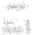
- FIG. 5is a pictorial representation of a side view of an exemplary intervertebral prosthetic device.
- FIG. 6is a pictorial representation of an end view of an exemplary intervertebral prosthetic device.
- FIG. 7is a pictorial representation showing inner features of an intervertebral prosthetic device.
- FIGS. 8A and 8Bare pictorial representations of an intervertebral prosthetic device in an intervertebral space.
- FIG. 9is a pictorial representation of intervertebral prosthetic devices disposed on a lower vertebra.
- FIG. 10is a pictorial representation of an isometric view of an exemplary intervertebral prosthetic device according to another aspect of this disclosure with an exploded fastener.
- FIG. 11is a pictorial representation of a side view of an exemplary intervertebral prosthetic device.
- FIG. 12is a pictorial representation of an exemplary intervertebral prosthetic device within an intervertebral disc space.
- the present inventionrelates generally to vertebral reconstructive devices and, more particularly, to an intervertebral prosthetic device for implantation.
- an intervertebral prosthetic devicefor implantation.
- FIG. 1shows a lateral view of a portion of a spinal column 10 , illustrating a group of adjacent upper and lower vertebrae V 1 , V 2 , V 3 , V 4 separated by natural intervertebral discs D 1 , D 2 , D 3 .
- the illustration of four vertebraeis only intended as an example. Another example would be a sacrum and one vertebrae.
- the two vertebraeform a spinal segment 12 including an upper vertebra 14 and a lower vertebra 16 .
- Some types of disc arthroplastyrequire that some or all of the natural disc that would have been positioned between the two vertebrae 14 , 16 be removed via a discectomy or a similar surgical procedure. Removal of the diseased or degenerated disc results in the formation of an intervertebral space S between the upper and lower vertebrae 14 , 16 .
- FIG. 2generally depicts the spinal segment 12 as a lumbar vertebral joint, it is understood that the devices, systems, and methods of this disclosure may also be applied to all regions of the vertebral column, including the cervical and thoracic regions. It should be understood that in this description and in the claims of this disclosure, the terms upper and lower vertebrae also contemplate vertebra that do not directly form the intervertebral space S, but that are at locations respectively above and below those vertebra that directly form the intervertebral space S.
- Some conventional spinal prosthetic devicesare installed using an anterior procedure, requiring a physician to access the spinal column using distressing and sometimes traumatic procedures. Once a prosthetic is installed using an anterior procedure, scar tissue may build on sensitive vessels. If a second procedure is required, a physician may be required to remove the scar tissue to access the previously placed prosthetic. This sensitive procedure can cause additional distress to the patient.
- the intervertebral prosthetic device disclosed hereinmay be advantageous over prior devices because it may be installed using a posterior procedure. Accordingly, a physician need not access and disturb the critical vessels that reside at the anterior side of the spinal column. Further, if a second procedure becomes necessary, the physician has easy access to the previously placed prosthetic without removing scar tissue off of sensitive vessels. Accordingly, the procedure may be simplified and may cause less distress to the patient.
- fastenersthat secure the prosthetic device in place.
- these fastenersare typically driven into the vertebral body.
- the vertebral bodies in some patients, including many older patientscan become weak, and may become less than desirable locations for anchoring. Because of this, over time, the fasteners in the vertebral body may become loose and begin to toggle, risking displacement of the implanted prosthetic disc.
- the fastenersalso may present additional problems. For example, fasteners are typically driven into the side of the vertebral body, just above or below the vertebral space. Accordingly, the fasteners might lie shallowly in the vertebra, in close proximity to the endplate.
- This shallow locationmay potentially slow the bone growth rate at the endplates, as the bone mates with the surface of the prosthetic device.
- the shallow location of the fastenermay weaken the endplate of the vertebra, and if subjected to extreme loads, the vertebra may split, potentially requiring additional surgeries and replacement prosthetic devices.
- the intervertebral prosthetic devices disclosed hereinmay allow the device fasteners to be introduced to the vertebra at a location spaced away from the vertebral endplate, and in some instances, into the pedicles rather than the vertebral bodies.
- FIGS. 3-7show a number of views of a prosthetic device 20 implantable in the intervertebral space S of FIG. 2 .
- FIGS. 8A and 8Bshow the prosthetic device 20 in place in the intervertebral space S.
- the prosthetic device 20allows the vertebra 14 to articulate relative to the vertebra 16 to provide movement to the spinal joint. Sized to fit the intervertebral space height in a manner similar to a natural intervertebral disc, such as any of discs D 1 -D 4 , the prosthetic device 20 provides support and stabilization to the vertebrae
- FIG. 3is an isometric view of the prosthetic device 20
- FIG. 4is a top view
- FIG. 5is a side view
- FIG. 6is an end view
- FIG. 7shows portions of the prosthetic device 20 separate to display inner features.
- the prosthetic device 20includes an upper articular portion 22 and a lower articular portion 24 .
- the upper articular portion 22includes an upper main body formed of an interdiscal section 26 , a posterior section 28 , and a bridge 30 extending between the interdiscal and posterior sections 26 , 28 .
- the lower articular portion 24includes a lower main body formed of an interdiscal section 32 , a posterior section 34 , and a bridge 36 extending between the interdiscal and posterior sections 32 , 34 .
- the upper and lower articular portions 22 , 24may be formed of any suitable biocompatible material including metals such as cobalt-chromium alloys, titanium alloys, nickel titanium alloys, and/or stainless steel alloys. Ceramic materials such as aluminum oxide or alumina, zirconium oxide or zirconia, compact of particulate diamond, and/or pyrolytic carbon may also be suitable.
- Polymer materialsmay also be used, including any member of the polyaryletherketone (PAEK) family such as polyetheretherketone (PEEK), carbon-reinforced PEEK, or polyetherketoneketone (PEKK); polysulfone; polyetherimide; polyimide; ultra-high molecular weight polyethylene (UHMWPE); and/or cross-linked UHMWPE.
- PAEKpolyaryletherketone
- PEEKpolyetheretherketone
- PEKKpolyetherketoneketone
- polysulfonepolyetherimide
- polyimidepolyimide
- UHMWPEultra-high molecular weight polyethylene
- UHMWPEultra-high molecular weight polyethylene
- the various sections comprising the upper articular portion 22 and the lower articular portion 24may be formed of different materials thus permitting metal on metal, metal on ceramic, metal on polymer, ceramic on ceramic, ceramic on polymer, or polymer on polymer constructions.
- each of the upper and lower articular portions 22 , 24are integrally formed or molded of a single piece of material.
- one or more of the interdiscal, posterior, and bridge sections of either of the upper or lower articular portions 22 , 24may be formed separately and attached to one or more of the other sections. Attachments in these embodiments may be accomplished using any fastening mechanism known in the art including, for example, a threaded connection, a bolted connection, or a latched connection, among others.
- the interdiscal, posterior, and bridge sectionsalso may be formed of different materials.
- the interdiscal section 26 of the upper articular portion 22may include a bone contacting surface 38 and an inner surface 44 opposite the bone contacting surface 38 .
- a first articular surface 42may form a part of the inner surface 44 ( FIG. 7 ).
- the first articular surface 42is a recess.
- the interdiscal section 32 of the lower articular portion 24may include a bone contacting surface 40 opposite an inner surface 48 , with a second articular surface 46 forming a part of the inner surface 48 ( FIG. 7 ) and being configured to mate with the first articular surface 42 .
- the second articular surface 46is a protrusion.
- first and second articular surfaces 42 , 46may form an articulating joint that allows the upper and lower articular portions 22 , 24 to articulate relative to each other.
- This articulationmay allow articulating movement of the upper vertebra 14 relative to the lower vertebra 16 , and in some embodiments, may allow movement similar to that provided by a natural spinal disc.
- the second articular surface 46is a partial sphere that may rotate or translate within the first articular surface 42 , forming a loosely constrained ball and socket style joint.
- first and second articular surfaces 42 , 46may be any shape or design that allows one of the upper and lower articular portions 22 , 24 to move relative to the other of the upper and lower articular portions 22 , 24 .
- the first and second articular surfaces 42 , 46may include a trough and recess, a ball and saucer, or other shaped features.
- the first and second articular surfaces 42 , 46are formed of a material different than the remainder of the interdiscal sections 26 , 32 to provide suitable articulation.
- the bone contacting surfaces 38 , 40 of the upper and lower articular portions 22 , 24may include features or coatings which enhance the fixation of the implanted prosthetic device 20 .
- the surfaces 38 , 40may be roughened such as by chemical etching, bead-blasting, sanding, grinding, serrating, and/or diamond-cutting. All or a portion of the bone contacting surfaces 38 , 40 of the upper and lower articular portions 22 , 24 may also be coated with a biocompatible and osteoconductive material such as hydroxyapatite (HA), tricalcium phosphate (TCP), and/or calcium carbonate to promote bone in growth and fixation.
- HAhydroxyapatite
- TCPtricalcium phosphate
- osteoinductive coatingssuch as proteins from transforming growth factor (TGF) beta superfamily, or bone-morphogenic proteins, such as BMP2 or BMP7, may be used.
- TGFtransforming growth factor
- BMP2 or BMP7bone-morphogenic proteins
- suitable featuresmay include spikes, ridges, and/or other surface textures and features.
- optional upper and lower bone connectors 50 , 52are formed on the bone contacting surfaces 38 , 40 , respectively. These bone connectors 50 , 52 extend toward the upper and lower vertebrae 14 , 16 in a manner to help secure the upper and lower articular portions 22 , 24 in place.
- the bone connectors 50 , 52are keels configured to extend into notches or grooves formed into the vertebral endplates.
- the bone connectorsalso could be a series of ridges, protrusions, or other surface features that help fix the prosthetic device 20 in place.
- the bridge sections 30 , 36extend rearward from the interdiscal sections 26 , 32 respectively.
- the bridge sections 30 , 36extend substantially along a longitudinal centerline 58 ( FIG. 4 ) of the prosthetic device 20 .
- the bridge sectionsdo not align with a longitudinal centerline of the interdiscal sections, but may be curved or angled to depart away from the longitudinal centerline.
- the posterior sections 28 , 34may be disposed at the end of the bridge sections 30 , 36 and, in some embodiments, may be configured to fit adjacent to the processes of the vertebrae 14 , 16 .
- the posterior section 34 of the lower articular portion 24may include a tail 60 extending generally in a direction along the spinal column, and past the posterior section 28 of the upper articular portion 22 .
- the tail 60may connect to the bridge section 36 and, in the example shown, is formed by a bend in the bridge section 36 . Extending upwardly, the tail 60 may be at least partially disposed at a location higher than the bridge section 36 . Part of the tail 60 may form a motion stop 66 ( FIG. 5 ) configured to limit the range of articulation between the upper and lower articular portions 22 , 24 . In the embodiment shown, the motion stop 66 is a bend in the tail 60 having a length that is configured to work together with the upper articular portion 22 to limit the available range of articular rotation of the upper and lower articular portions 22 , 24 . It should be noted that the tail 60 may be substantially straight or may be curved, angled or otherwise formed. In one exemplary embodiment, the tail 60 may include a curve concentric with the curvature of the protruding articular surface 46 .
- the posterior section 28 of the upper articular portion 22includes an aperture 70 formed therein that is configured to receive the tail 60 of the lower articular portion 24 .
- a portion of the posterior section 28forms a motion stop 69 that is configured to cooperate with the motion stop 66 on the tail 60 .
- the motion stop 66 and the motion stop 69cooperate to limit the range of articulation of the prosthetic device 20 .
- the aperture 70is configured so that when the articulating surfaces 42 , 46 are mated, the tail 60 extends through the aperture 70 in a manner that articulation may still freely occur within the range.
- the upper and lower articular portions 22 , 24may be configured for assembly when outside of the intervertebral space S of FIG. 2 . Further, the upper and lower articular portions 22 , 24 may be difficult to disassemble within the intervertebral space S. Therefore, the chance of the upper and lower articular portions 22 , 24 becoming misaligned after implantation is reduced. Furthermore, the tail 60 and aperture 70 reduce the chance of axial rotation of one of the upper and lower articular portions 22 , 24 about the other of the upper and lower articular portions 22 , 24 . Accordingly, despite forming a ball and socket joint, the upper and lower articular portions 22 , 24 are bound together so that axial rotation is limited by the aperture 70 and the tail 60 .
- the upper articular portionincludes an attachment element, such as a plate 72 , extending upwardly from the upper main body of the upper articular portion 22 and a fastener 74 .
- the plate 72is configured to connect the fastener 74 to the upper main body, and is configured to lie along the pedicle of the adjacent vertebra so that the fastener 74 extends into the pedicle ( FIGS. 8A and 8B ).
- the plate 72has a width greater than the width of the bridge 30 and extends from the bridge.
- An aperture 76allows passage of the fastener 74 through the plate 72 into the adjacent vertebra.
- the aperture 76includes a scalloped profile 78 that, in the example shown, is formed by overlapping holes, with each hole allowing passage of the fastener 74 .
- the scalloped profile 78is formed of two separate sections showing two holes each, providing four placement options for the fastener. Accordingly, a physician implanting the prosthetic device 20 may choose which of the available options to insert the fastener 74 . It should be noted that in other embodiments, a different number of apertures or holes may be used.
- the fastener 74may be a bone screw having a threaded portion 80 for insertion into bone and a head 82 operable to press against the plate 72 to secure the plate against the bone.
- the fastener 74may be inserted into the bone substantially in a plane formed through the longitudinal axis, and in the embodiment shown, the fastener 74 is substantially parallel to the longitudinal axis.
- the headitself has a diameter greater than the diameter of the holes of the scalloped profile 78 of the plate 72 and is in contact with the plate. Washers or other hardware may be used with the fastener 74 to secure the plate to the bone.
- One exemplary fastener suitable for use with the plate 72is described further below with reference to FIG. 10 .
- the fastener 74may be any other fastener that can secure the plate in place.
- a joint 84may allow the plate 72 to move relative to the upper main body of the upper articular portion 22 .
- the joint 84is a hinge providing movement of the plate 72 relative to the upper main body along the direction of the longitudinal centerline 58 .
- Providing a degree of freedom to the plate 72may allow simpler placement of the plate 72 against the pedicle and may compensate for any space between the plate and the pedicle.
- securing the plate 72 in place to the pedicle and securely locating the interdiscal section 26 of the upper articular portion 22 to the endplate of the vertebra 14effectively locks the joint 84 in place.
- the plate 72 and joint 84allow the prosthetic device 20 to be fastened to the pedicle, rather than the vertebral body by providing an attachment location spaced away from the intervertebral space S. Accordingly, the prosthetic device 20 is connected to the stronger bones in the vertebral column, that provide additional support. This may reduce the chance of the fastener coming loose or toggling over time. This also reduces problems that might arise when the fastener is disposed very close to the vertebral endplates. This may find particular utility in patients whose vertebral bodies may have began to grow relatively brittle.
- FIGS. 8A and 8Bare side views of the prosthetic device 20 between upper and lower vertebrae 14 , 16 .
- the interdiscal section 26may be situated along an inferior surface of the upper vertebra 14 and the interdiscal section 32 may be situated above a superior surface of the lower vertebra 16 .
- the two interdiscal sections 26 , 32are not limited to such an arrangement, and may be oriented in different positions and/or shaped differently than what is illustrated herein.
- FIG. 8Ashows the device 20 when the spinal column is in a natural position
- FIG. 8Bshows the device 20 when the spinal column is in flexion
- the prosthetic device 20also allows articulation in extension.
- FIG. 8Bwhen in flexion, the motion stop 69 on the posterior section 28 of the upper articular portion 22 is in contact with the motion stop 66 of the lower articular portion 24 . Accordingly, a flexion/extension and/or torsional articulation range of the prosthetic device 20 is limited to the amount allowed by the motion stops 66 and 69 .
- FIG. 8Ashows the prosthetic device 20 articulated to a substantially central position, with the aperture 70 being disposed about the middle region of the tail 60 .
- the articulation rangeis limited by the bridge sections 30 , 36 , which can act as motion stops to limit the articulation between the upper and lower articular portions 22 , 24 .
- the total range of motion of the prosthetic device 20may be about 45 degrees. However, the range of motion could be more or less than this, as controlled by the motion stops.
- FIG. 9shows a top view of the prosthetic device 20 in place on the lower vertebra 16 .
- the prosthetic device 20may be configured for placement on one half of an interdiscal space, while a second prosthetic device 20 may be placed on the other half of the interdiscal space.
- a complete prosthetic discmay include a pair of prosthetic devices 20 , one for the left and the other for the right, that cooperate together to take the place of the natural disc. It should be readily apparent that the right and left prosthetic devices 20 may be substantially similar in structure and function.
- FIGS. 10-12Another embodiment of an articular prosthetic device 100 is shown in FIGS. 10-12 .
- the articular prosthetic device 100has many features similar to the articular prosthetic device 20 described above. A detailed description of these features will not be repeated here. However, it is understood that any feature described above with respect to the device 20 may be applied to the device 100 and vice-versa.
- the articular prosthetic device 100includes an upper articular portion 102 and a lower articular portion 104 , each having an interdiscal section 106 , 108 and each having a posterior section 110 , 112 , respectively.
- the prosthetic device 100includes an attachment element, such as a tail 114 , extending from the lower articular portion 104 , through the aperture in the upper articular portion 102 , to connect to the upper vertebra 14 . Therefore, in this embodiment, the lower articular portion 104 connects to the upper vertebra 14 .
- a healthy vertebral columndistributes carried loads so that about 80% of the load is carried in the anterior regions of the vertebrae and about 20% of the load is carried in the facets.
- the anterior regions of the vertebraetypically carries a full 100% of the load.
- the tail 114connects the upper vertebra 14 to the lower articular portion 104 so that a percentage of any applied loads are carried not solely by the anterior portions of the vertebra, but also by the posterior portion. Accordingly, by distributing applied loads between both the anterior portion and the posterior portion, the prosthetic device 100 has a load distribution that more closely matches the natural vertebral column than does conventional prosthetic devices.
- posterior implantation proceduresoften include removal of facet joints or processes that operate as connection locations for ligaments and muscles, their removal may limit the ability of the joint to control the range of joint articulation.
- conventional prosthetic devices implanted through a posterior procedureprovide articulation, but it may be largely uncontrolled. With the removal of the muscles and ligaments, the repaired joint may become floppy.
- the intervertebral prosthetic device disclosed hereinmay dampen the articulation, thereby providing more stability and more control to the spinal column.
- the tail 114includes a lower tail portion 120 , an upper tail portion 122 , and a flexible bumper 124 .
- the lower tail portion 120may be formed similar to the tail 60 described above, and may be an integral part of the lower articular portion 104 or alternatively, may be connected to the lower articular portion 104 through a connector such as, for example, a joint, a bracket, or other system.
- the upper tail portion 122is suitable for attachment to a fastener 126 .
- the upper tail portion 122is a straight rod.
- the upper tail portion 122may be straight or curved to provide leverage and desired load distribution to the lower articular portion 104 .
- the upper and lower tail portions 122 , 120may be formed of any material suitable for the prosthetic device 100 . In some embodiments, the upper and lower tail portions 122 , 120 are formed of the same material, while in others, they are formed of different materials.
- the flexible bumper 124may allow for relative movement between the upper and lower tail portions 122 , 120 . This mobility enables the upper and lower vertebrae 14 , 16 to move in flexion and extension despite the lower articular portion 104 being connected to both the upper and lower vertebrae 14 , 16 .
- the flexible bumper 124may be formed of any suitable biocompatible material including, for example, elastomeric materials and polymers, among other materials. In the example shown, the flexible bumper 124 is in-line with the upper and lower tail portions 122 , 120 . However, in other embodiments, the flexible bumper 124 may have a diameter or thickness greater than or less than the diameter or thickness of the upper and lower tail portions 122 , 120 .
- the flexible bumper 124is over-molded onto the upper and lower tail portions 122 , 120 .
- the upper and lower tail portions 122 , 120may be secured through a metal cable extending from the upper to the lower tail portion, with an elastomeric cushion provided to transfer loads at the posterior of the vertebral column.
- the cablemay be secured at each end, for example, within the upper and lower tail portions 122 , 120 , and may limit the range of extension, while the flexible bumper 124 may control the amount of flexion.
- the cableis not secured to limit the range of flexion or extension, and instead simply secures the various tail portions together.
- the fastener 126may be configured to adjustably connect to the vertebra 14 and the upper tail portion 122 .
- the fastener 126includes a bone section 128 and a head section 130 .
- the bone section 128may include threads and may configured to connect to the bone in a manner known in the art.
- the head section 130is formed with a U-shape configured to receive the upper tail portion 122 .
- a set-screw 132may be driven into the U-shape, securing the upper tail portion 122 in place between the set-screw 132 and the base of the U-shape.
- the set-screw 132includes outer threads that mate with inner threads in the U-shape. Loosening the set screw 132 releases the tail 114 , which can then by adjusted or manipulated to a desired position. Tightening the set screw 132 then secures the tail 114 in place.
- the fastener 126may be driven into the vertebra in a direction substantially parallel to a longitudinal axis 134 of the prosthetic device 100 .
- the fastener 126is driven into the pedicles, while in another embodiment, the fastener is driven into the vertebral body.
- the prosthetic devices 20 , 100may be implanted between the vertebrae 14 , 16 as will be described below.
- the artificial intervertebral prosthetic devices 20 , 100may be implanted into a body using a posterior transforaminal approach similar to the known transforaminal lumbar interbody fusion (TLIF) or posterior lumbar interbody fusion (PLIF) procedures.
- TLIF approachesare generally more medial and rely on more retraction of the traversing root and dura to access the vertebral interspace.
- TLIF approachesare typically more oblique, requiring less retraction of the exiting root, and less epidural bleeding with less retraction of the traversing structures.
- an incisionsuch as a midline incision, may be made in the patient's back and some or all of the affected disc and surrounding tissue may be removed via the foramina.
- the superior endplate surface of the vertebra 14may be milled, rasped, or otherwise resected to match the profile of the bone contacting surface of the upper articular portion to normalize stress distributions on the superior endplate surface of the vertebra 14 and/or to provide initial fixation prior to bone ingrowth.
- the preparation of the endplate of vertebra 14may result in a flattened surface or in surface contours such as pockets, grooves, or other contours that may match corresponding features on the bone contacting surface 38 .
- the inferior endplate of the vertebra 16may be similarly prepared to receive the lower articular portion to the extent allowed by the exiting nerve root and the dorsal root ganglia. In some procedures, the natural facet joints of vertebrae 14 , 16 may be trimmed or removed to make room for the posterior sections of the articular portions.
- the upper and lower articular portions of the prosthetic devicemay then be oriented so that the tail extends through the aperture.
- the upper and lower articular portionsthen may be simultaneously introduced into the transforaminal openings and are placed in the appropriate intervertebral disc space between the upper and lower vertebrae.
- the upper and lower articular portionsmay be introduced through a cannula. If the pieces are modular, the prosthetic device may be implanted pieces at a time, with posterior sections of the upper and lower articular portions introduced last.
- the bridge sectionsmay extend in a posterior direction from the interdiscal sections and in a posterior direction from the intervertebral intervertebral space S.
- the posterior sectionsare positioned in a posterior direction of the intervertebral disc space to replace or supplement the function of the natural facet joints.
- the plate 72may be rotated about its joint 84 so that it is in contact with the bone.
- the physicianmay select an appropriate hole in the aperture 76 with its scalloped profile 78 for introducing the fastener 74 .
- the selectionmay be based upon the location that the physician believes is most ideal for securing the fastener 74 into the bone.
- a holemay be drilled into the bone through the aperture, and the fastener 74 may be driven into the hole.
- the plateis not in direct contact with the bone, but spacers, washers, or bumpers may be disposed between the plate and the bone.
- the physicianmay select an appropriate location to place the fastener 126 , preferably at a location that permits the flexible bumper 124 on the tail 114 to be disposed between the fastener 126 and the intervertebral space S.
- a holemay be drilled into the bone and the fastener 126 may be driven into the hole.
- the tail 114then may be secured to the fastener 126 outside the discal space S.
- the ball and socket type joint created by the articular surfaces 42 , 46may be relatively stable and self-centering. Both the anterior joint and the posterior connection (formed by the tail and aperture connection) allow the prosthetic device 20 to resist shear forces, particularly anterior-posterior forces. Further, rotational motion about a longitudinal centerline defined by the cylindrical bodies 14 , 16 may be limited both by the constraint in the tail and aperture connection and by the combined constraint provided by utilizing two prosthetic devices.
- the robust and forgiving structure of the anterior joint and the tail and aperture connectionpermits misalignment and slight inaccuracy in the placement of the prosthetic devices.
- the ball and socket structure of the articular jointtolerates a certain amount of misalignment between the components.
- the interaction of the tail and aperturemay also accommodate parallel misalignment and/or anterior-posterior misalignment between the prosthetic devices 20 , 21 .
- a single unilateral prosthetic devicemay be implanted, while in others, two devices, forming a right and a left device may be implanted.
- the tail 114is formed of a single rigid piece and a flexible bumper.
- the tailmay include a lower tail portion that extends from the articular portion.
- the flexible bumperthen may extend from the lower portion and be secured in the fastener.
- an upper tail portionmay be eliminated from the design.
- the tail portionis formed entirely of the flexible bumper, so that the entire tail is flexible.
- Other embodiments, including multiple flexible portions and multiple rigid portionsare also contemplated.
- both the upper and lower articular portionsinclude tails having at least a flexible portion.
- the tailsextend past each other so that the tail from the lower articular portion extends to connect to the upper vertebra and the tail from the upper articular portion extends to connect to the lower vertebra.
- These tailsmay be formed to have similar or different levels of flexibility to provide desired dampening and load distribution.
- the upper and lower articular portionsmay or may not include apertures for receiving the opposing tails.
- both the upper and lower articular portionsinclude plates. These plates may extend from the main bodies of the articular portions and allow each articular portion to be secured to the respective vertebra. Each plate may have one or more apertures, that may be scalloped, that provide more than a single location for a fastener. It should be noted than in any embodiment, the plate may be connected to the main body of the articular portion at locations other than the bridge section. For example, in some embodiments, the plate extends from the posterior section.
- the prosthetic deviceincludes both plates and a tail having a flexible bumper.
- the plate and the tailmay use the same fastening screw or separate fastening screws.
Landscapes
- Health & Medical Sciences (AREA)
- Engineering & Computer Science (AREA)
- Biomedical Technology (AREA)
- Orthopedic Medicine & Surgery (AREA)
- Neurology (AREA)
- Heart & Thoracic Surgery (AREA)
- Oral & Maxillofacial Surgery (AREA)
- Transplantation (AREA)
- Cardiology (AREA)
- Vascular Medicine (AREA)
- Life Sciences & Earth Sciences (AREA)
- Animal Behavior & Ethology (AREA)
- General Health & Medical Sciences (AREA)
- Public Health (AREA)
- Veterinary Medicine (AREA)
- Prostheses (AREA)
- Surgical Instruments (AREA)
Abstract
Description
- U.S. Utility patent application Ser. No. 11/031,602, filed on Jan. 7, 2005 and entitled “Spinal Arthroplasty Device and Method;”
- U.S. Utility patent application Ser. No. 11/031,603, filed on Jan. 7, 2005 and entitled “Dual Articulating Spinal Device and Method;”
- U.S. Utility patent application Ser. No. 11/031,780, filed on Jan. 7, 2005 and entitled “Split Spinal Device and Method;”
- U.S. Utility patent application Ser. No. 11/031,904, filed on Jan. 7, 2005 and entitled “Interconnected Spinal Device and Method;”
- U.S. Utility patent application Ser. No. 11/031,700, filed on Jan. 7, 2005 and entitled “Support Structure Device and Method;”
- U.S. Utility patent application Ser. No. 11/031,783, filed on Jan. 7, 2005 and entitled “Mobile Bearing Spinal Device and Method;”
- U.S. Utility patent application Ser. No. 11/031,781, filed on Jan. 7, 2005 and entitled “Centrally Articulating Spinal Device and Method;” and
- U.S. Utility patent application Ser. No. 11/031,903, filed on Jan. 7, 2005 and entitled “Posterior Spinal Device and Method.”
Claims (13)
Priority Applications (7)
| Application Number | Priority Date | Filing Date | Title |
|---|---|---|---|
| US11/342,961US7635389B2 (en) | 2006-01-30 | 2006-01-30 | Posterior joint replacement device |
| KR1020087021154AKR20080093141A (en) | 2006-01-30 | 2007-01-12 | Artificial instruments for spinal joint reconstruction |
| AU2007208185AAU2007208185A1 (en) | 2006-01-30 | 2007-01-12 | Prosthetic device for spinal joint reconstruction |
| EP07762459AEP1983943A1 (en) | 2006-01-30 | 2007-01-12 | Prosthetic device for spinal joint reconstruction |
| JP2008553435AJP2009525147A (en) | 2006-01-30 | 2007-01-12 | Prosthetic device for spinal joint reconstruction |
| CNA2007800075097ACN101394813A (en) | 2006-01-30 | 2007-01-12 | Prosthetic device for spinal joint reconstruction |
| PCT/US2007/060491WO2007087477A1 (en) | 2006-01-30 | 2007-01-12 | Prosthetic device for spinal joint reconstruction |
Applications Claiming Priority (1)
| Application Number | Priority Date | Filing Date | Title |
|---|---|---|---|
| US11/342,961US7635389B2 (en) | 2006-01-30 | 2006-01-30 | Posterior joint replacement device |
Publications (2)
| Publication Number | Publication Date |
|---|---|
| US20070191945A1 US20070191945A1 (en) | 2007-08-16 |
| US7635389B2true US7635389B2 (en) | 2009-12-22 |
Family
ID=37907128
Family Applications (1)
| Application Number | Title | Priority Date | Filing Date |
|---|---|---|---|
| US11/342,961Active2026-05-17US7635389B2 (en) | 2006-01-30 | 2006-01-30 | Posterior joint replacement device |
Country Status (7)
| Country | Link |
|---|---|
| US (1) | US7635389B2 (en) |
| EP (1) | EP1983943A1 (en) |
| JP (1) | JP2009525147A (en) |
| KR (1) | KR20080093141A (en) |
| CN (1) | CN101394813A (en) |
| AU (1) | AU2007208185A1 (en) |
| WO (1) | WO2007087477A1 (en) |
Cited By (10)
| Publication number | Priority date | Publication date | Assignee | Title |
|---|---|---|---|---|
| US20080015694A1 (en)* | 2006-01-13 | 2008-01-17 | Clifford Tribus | Spine reduction and stabilization device |
| US20080077245A1 (en)* | 2006-04-20 | 2008-03-27 | Lee Casey K | Intervertebral disc and facet joint prosthesis |
| US20080234684A1 (en)* | 2007-02-08 | 2008-09-25 | Warsaw Orthopedic, Inc. | Instruments and techniques for guiding instruments to a spinal column |
| US20080269904A1 (en)* | 2007-04-26 | 2008-10-30 | Voorhies Rand M | Lumbar disc replacement implant for posterior implantation with dynamic spinal stabilization device and method |
| US20090030518A1 (en)* | 2007-06-01 | 2009-01-29 | Carl-Eric Aubin | Fusionless Vertebral Physeal Device and Method |
| US20130325071A1 (en)* | 2012-05-30 | 2013-12-05 | Marcin Niemiec | Aligning Vertebral Bodies |
| US8864832B2 (en)* | 2007-06-20 | 2014-10-21 | Hh Spinal Llc | Posterior total joint replacement |
| US8956414B2 (en) | 2010-04-21 | 2015-02-17 | Spinecraft, LLC | Intervertebral body implant, instrument and method |
| US9358122B2 (en) | 2011-01-07 | 2016-06-07 | K2M, Inc. | Interbody spacer |
| US9839451B2 (en) | 2016-03-29 | 2017-12-12 | Christopher D. Sturm | Facet joint replacement device and methods of use |
Families Citing this family (25)
| Publication number | Priority date | Publication date | Assignee | Title |
|---|---|---|---|---|
| US7588590B2 (en) | 2003-12-10 | 2009-09-15 | Facet Solutions, Inc | Spinal facet implant with spherical implant apposition surface and bone bed and methods of use |
| US20050171608A1 (en) | 2004-01-09 | 2005-08-04 | Sdgi Holdings, Inc. | Centrally articulating spinal device and method |
| US7771479B2 (en) | 2004-01-09 | 2010-08-10 | Warsaw Orthopedic, Inc. | Dual articulating spinal device and method |
| US8333789B2 (en) | 2007-01-10 | 2012-12-18 | Gmedelaware 2 Llc | Facet joint replacement |
| US8562649B2 (en) | 2004-02-17 | 2013-10-22 | Gmedelaware 2 Llc | System and method for multiple level facet joint arthroplasty and fusion |
| US7918891B1 (en) | 2004-03-29 | 2011-04-05 | Nuvasive Inc. | Systems and methods for spinal fusion |
| US7507242B2 (en) | 2004-06-02 | 2009-03-24 | Facet Solutions | Surgical measurement and resection framework |
| US8328851B2 (en) | 2005-07-28 | 2012-12-11 | Nuvasive, Inc. | Total disc replacement system and related methods |
| US7811326B2 (en) | 2006-01-30 | 2010-10-12 | Warsaw Orthopedic Inc. | Posterior joint replacement device |
| US7635389B2 (en) | 2006-01-30 | 2009-12-22 | Warsaw Orthopedic, Inc. | Posterior joint replacement device |
| US20070270862A1 (en)* | 2006-03-30 | 2007-11-22 | Sdgi Holdings, Inc. | Instruments and methods for preparing an intervertebral space |
| US8075596B2 (en) | 2007-01-12 | 2011-12-13 | Warsaw Orthopedic, Inc. | Spinal prosthesis systems |
| US8673005B1 (en) | 2007-03-07 | 2014-03-18 | Nuvasive, Inc. | System and methods for spinal fusion |
| US10821003B2 (en) | 2007-06-20 | 2020-11-03 | 3Spline Sezc | Spinal osteotomy |
| US8083796B1 (en) | 2008-02-29 | 2011-12-27 | Nuvasive, Inc. | Implants and methods for spinal fusion |
| USD754346S1 (en) | 2009-03-02 | 2016-04-19 | Nuvasive, Inc. | Spinal fusion implant |
| DE102009011563A1 (en)* | 2009-03-06 | 2010-09-09 | Heinrich Dr. Böhm | Implant for the thoracic and lumbar spine |
| US9387090B2 (en) | 2009-03-12 | 2016-07-12 | Nuvasive, Inc. | Vertebral body replacement |
| US9687357B2 (en) | 2009-03-12 | 2017-06-27 | Nuvasive, Inc. | Vertebral body replacement |
| US9351845B1 (en) | 2009-04-16 | 2016-05-31 | Nuvasive, Inc. | Method and apparatus for performing spine surgery |
| US8287597B1 (en) | 2009-04-16 | 2012-10-16 | Nuvasive, Inc. | Method and apparatus for performing spine surgery |
| US9198765B1 (en) | 2011-10-31 | 2015-12-01 | Nuvasive, Inc. | Expandable spinal fusion implants and related methods |
| EP2777628B1 (en)* | 2013-03-15 | 2018-02-28 | Neos Surgery, S.L. | Device for repairing an intervertebral disc |
| CA3119074A1 (en)* | 2018-11-09 | 2020-05-14 | Marc Peterman | Intervertebral spinal implant and surgical methods |
| US12409046B2 (en) | 2022-04-12 | 2025-09-09 | 3Spine, Inc. | Total spinal joint systems with motion moderators |
Citations (240)
| Publication number | Priority date | Publication date | Assignee | Title |
|---|---|---|---|---|
| US4349921A (en) | 1980-06-13 | 1982-09-21 | Kuntz J David | Intervertebral disc prosthesis |
| US4697586A (en) | 1986-06-24 | 1987-10-06 | Gazale William J | Combined chisel-guide surgical instrument |
| US4697582A (en) | 1983-10-28 | 1987-10-06 | Peze William | Appliance for correcting rachidial deformities |
| US4702930A (en) | 1984-12-28 | 1987-10-27 | Battelle-Institute E.V. | Method of producing implantable bone replacement materials |
| US4759769A (en) | 1987-02-12 | 1988-07-26 | Health & Research Services Inc. | Artificial spinal disc |
| US4836196A (en) | 1988-01-11 | 1989-06-06 | Acromed Corporation | Surgically implantable spinal correction system |
| US4932975A (en) | 1989-10-16 | 1990-06-12 | Vanderbilt University | Vertebral prosthesis |
| US5092866A (en) | 1989-02-03 | 1992-03-03 | Breard Francis H | Flexible inter-vertebral stabilizer as well as process and apparatus for determining or verifying its tension before installation on the spinal column |
| FR2676911A1 (en) | 1991-05-30 | 1992-12-04 | Psi Ste Civile Particuliere | INTERVERTEBRAL STABILIZATION DEVICE WITH SHOCK ABSORBERS. |
| US5258031A (en) | 1992-01-06 | 1993-11-02 | Danek Medical | Intervertebral disk arthroplasty |
| US5282863A (en) | 1985-06-10 | 1994-02-01 | Charles V. Burton | Flexible stabilization system for a vertebral column |
| US5387213A (en) | 1991-02-05 | 1995-02-07 | Safir S.A.R.L. | Osseous surgical implant particularly for an intervertebral stabilizer |
| US5401269A (en) | 1992-03-13 | 1995-03-28 | Waldemar Link Gmbh & Co. | Intervertebral disc endoprosthesis |
| US5415661A (en) | 1993-03-24 | 1995-05-16 | University Of Miami | Implantable spinal assist device |
| US5423825A (en) | 1992-06-10 | 1995-06-13 | Levine; Andrew S. | Spinal fusion instruments and methods |
| US5443515A (en) | 1994-01-26 | 1995-08-22 | Implex Corporation | Vertebral body prosthetic implant with slidably positionable stabilizing member |
| US5458864A (en) | 1989-11-16 | 1995-10-17 | Nissan Chemical Industries Ltd. | Process for producing high-purity silica by reacting crude silica with ammonium fluoride |
| EP0677277A2 (en) | 1994-03-18 | 1995-10-18 | Patrice Moreau | Spinal prosthetic assembly |
| WO1996000049A1 (en) | 1994-06-24 | 1996-01-04 | Fairant, Paulette | Vertebral articular facet prostheses |
| US5507816A (en) | 1991-12-04 | 1996-04-16 | Customflex Limited | Spinal vertebrae implants |
| US5556431A (en) | 1992-03-13 | 1996-09-17 | B+E,Uml U+Ee Ttner-Janz; Karin | Intervertebral disc endoprosthesis |
| US5562737A (en) | 1993-11-18 | 1996-10-08 | Henry Graf | Extra-discal intervertebral prosthesis |
| US5562660A (en) | 1993-02-09 | 1996-10-08 | Plus Endoprothetik Ag | Apparatus for stiffening and/or correcting the vertebral column |
| US5562738A (en) | 1992-01-06 | 1996-10-08 | Danek Medical, Inc. | Intervertebral disk arthroplasty device |
| US5571109A (en) | 1993-08-26 | 1996-11-05 | Man Ceramics Gmbh | System for the immobilization of vertebrae |
| US5607425A (en) | 1993-10-08 | 1997-03-04 | Rogozinski; Chaim | Apparatus, method and system for the treatment of spinal conditions |
| US5672175A (en) | 1993-08-27 | 1997-09-30 | Martin; Jean Raymond | Dynamic implanted spinal orthosis and operative procedure for fitting |
| US5674296A (en) | 1994-11-14 | 1997-10-07 | Spinal Dynamics Corporation | Human spinal disc prosthesis |
| US5676701A (en) | 1993-01-14 | 1997-10-14 | Smith & Nephew, Inc. | Low wear artificial spinal disc |
| US5702450A (en) | 1993-06-28 | 1997-12-30 | Bisserie; Michel | Intervertebral disk prosthesis |
| US5728098A (en) | 1996-11-07 | 1998-03-17 | Sdgi Holdings, Inc. | Multi-angle bone screw assembly using shape-memory technology |
| US5752957A (en) | 1997-02-12 | 1998-05-19 | Third Millennium Engineering, Llc | Polyaxial mechanism for use with orthopaedic implant devices |
| US5772661A (en) | 1988-06-13 | 1998-06-30 | Michelson; Gary Karlin | Methods and instrumentation for the surgical correction of human thoracic and lumbar spinal disease from the antero-lateral aspect of the spine |
| US5895428A (en) | 1996-11-01 | 1999-04-20 | Berry; Don | Load bearing spinal joint implant |
| US5899941A (en) | 1997-12-09 | 1999-05-04 | Chubu Bearing Kabushiki Kaisha | Artificial intervertebral disk |
| USRE36221E (en) | 1989-02-03 | 1999-06-01 | Breard; Francis Henri | Flexible inter-vertebral stabilizer as well as process and apparatus for determining or verifying its tension before installation on the spinal column |
| US5928284A (en) | 1998-07-09 | 1999-07-27 | Mehdizadeh; Hamid M. | Disc replacement prosthesis |
| US5961516A (en) | 1996-08-01 | 1999-10-05 | Graf; Henry | Device for mechanically connecting and assisting vertebrae with respect to one another |
| WO1999053871A1 (en) | 1998-04-23 | 1999-10-28 | Cauthen Research Group, Inc. | Articulating spinal implant |
| US6019792A (en) | 1998-04-23 | 2000-02-01 | Cauthen Research Group, Inc. | Articulating spinal implant |
| WO2000004851A1 (en) | 1998-07-22 | 2000-02-03 | Spinal Dynamics Corporation | Threaded cylindrical multidiscoid single or multiple array disc prosthesis |
| US6036088A (en) | 1995-03-15 | 2000-03-14 | Hitachi, Ltd | Method and apparatus for processing IC card found |
| US6039763A (en) | 1998-10-27 | 2000-03-21 | Disc Replacement Technologies, Inc. | Articulating spinal disc prosthesis |
| US6042582A (en) | 1997-05-20 | 2000-03-28 | Ray; Charles D. | Instrumentation and method for facilitating insertion of spinal implant |
| USRE36758E (en) | 1995-03-16 | 2000-06-27 | Fitz; William R. | Artificial facet joint |
| US6106557A (en) | 1998-07-23 | 2000-08-22 | Howmedica Gmbh | Reconstruction system for vertebra |
| US6113637A (en) | 1998-10-22 | 2000-09-05 | Sofamor Danek Holdings, Inc. | Artificial intervertebral joint permitting translational and rotational motion |
| US6146421A (en) | 1997-08-04 | 2000-11-14 | Gordon, Maya, Roberts And Thomas, Number 1, Llc | Multiple axis intervertebral prosthesis |
| US6159211A (en) | 1998-10-22 | 2000-12-12 | Depuy Acromed, Inc. | Stackable cage system for corpectomy/vertebrectomy |
| US6159214A (en) | 1996-07-31 | 2000-12-12 | Michelson; Gary K. | Milling instrumentation and method for preparing a space between adjacent vertebral bodies |
| US6159244A (en) | 1999-07-30 | 2000-12-12 | Suddaby; Loubert | Expandable variable angle intervertebral fusion implant |
| US6174311B1 (en) | 1998-10-28 | 2001-01-16 | Sdgi Holdings, Inc. | Interbody fusion grafts and instrumentation |
| US6179875B1 (en) | 1998-06-17 | 2001-01-30 | Ulrich Gmbh & Co. Kg | Implant for fusing lumbar vertebrae and method of using same |
| US6190414B1 (en) | 1996-10-31 | 2001-02-20 | Surgical Dynamics Inc. | Apparatus for fusion of adjacent bone structures |
| US6193757B1 (en) | 1998-10-29 | 2001-02-27 | Sdgi Holdings, Inc. | Expandable intervertebral spacers |
| US6200322B1 (en) | 1999-08-13 | 2001-03-13 | Sdgi Holdings, Inc. | Minimal exposure posterior spinal interbody instrumentation and technique |
| US6224607B1 (en) | 1999-01-25 | 2001-05-01 | Gary K. Michelson | Instrumentation and method for creating an intervertebral space for receiving an implant |
| US6224599B1 (en) | 1999-05-19 | 2001-05-01 | Matthew G. Baynham | Viewable wedge distractor device |
| US6228118B1 (en) | 1997-08-04 | 2001-05-08 | Gordon, Maya, Roberts And Thomas, Number 1, Llc | Multiple axis intervertebral prosthesis |
| US6231609B1 (en) | 1998-07-09 | 2001-05-15 | Hamid M. Mehdizadeh | Disc replacement prosthesis |
| US6235059B1 (en) | 1996-04-03 | 2001-05-22 | Scient'x (Societe A Responsabilite Limitee) | Intersomatic setting and fusion system |
| WO2001039678A1 (en) | 1999-12-01 | 2001-06-07 | Henry Graf | Intervertebral stabilising device |
| US6251112B1 (en) | 2000-04-18 | 2001-06-26 | Roger P. Jackson | Thin profile closure cap for open ended medical implant |
| WO2001045576A1 (en) | 1999-12-20 | 2001-06-28 | Synthes Ag Chur | Device for the stabilisation of two adjacent verterbral bodies of the spine |
| US20010005796A1 (en) | 1995-03-27 | 2001-06-28 | Thomas Zdeblick | Methods and instruments for interbody fusion |
| US20010010021A1 (en) | 1999-01-08 | 2001-07-26 | Boyd Lawrence M. | Flexible implant using partially demineralized bone |
| US6277122B1 (en) | 1999-10-15 | 2001-08-21 | Sdgi Holdings, Inc. | Distraction instrument with fins for maintaining insertion location |
| US20010016773A1 (en) | 1998-10-15 | 2001-08-23 | Hassan Serhan | Spinal disc |
| US20010016774A1 (en) | 1998-10-20 | 2001-08-23 | Bresina Stephen J. | Strain regulating fusion cage for spinal fusion surgery |
| US20010032020A1 (en) | 1999-07-02 | 2001-10-18 | Petrus Besselink | Reinforced expandable cage |
| US20010034553A1 (en) | 2000-02-04 | 2001-10-25 | Michelson Gary Karlin | Expandable push-in arcuate interbody spinal fusion implant with tapered configuration during insertion |
| US20010047207A1 (en) | 1998-10-30 | 2001-11-29 | Michelson Gary K. | Self-broaching, rotatable, push-in interbody spinal fusion implant and method for deployment thereof |
| US6325827B1 (en) | 1999-02-01 | 2001-12-04 | Blacksheep Technologies, Inc. | Intervertebral implant |
| US20010049560A1 (en) | 1998-01-30 | 2001-12-06 | Paul David C. | Intervertebral allograft spacer |
| US6368350B1 (en) | 1999-03-11 | 2002-04-09 | Sulzer Spine-Tech Inc. | Intervertebral disc prosthesis and method |
| US20020045943A1 (en) | 2000-10-17 | 2002-04-18 | Uk Chang Jong | Prosthetic device for correcting deformity of spine |
| US20020049394A1 (en) | 2000-08-25 | 2002-04-25 | The Cleveland Clinic Foundation | Apparatus and method for assessing loads on adjacent bones |
| US20020049497A1 (en) | 2000-10-11 | 2002-04-25 | Mason Michael D. | Graftless spinal fusion device |
| US20020052656A1 (en) | 2000-02-04 | 2002-05-02 | Michelson Gary Karlin | Expandable push-in interbody spinal fusion implant |
| US20020068976A1 (en) | 2000-12-04 | 2002-06-06 | Jackson Roger P. | Posterior expandable fusion cage |
| US20020068977A1 (en) | 2000-12-05 | 2002-06-06 | Jackson Roger P. | Anterior variable expandable fusion cage |
| US6402750B1 (en) | 2000-04-04 | 2002-06-11 | Spinlabs, Llc | Devices and methods for the treatment of spinal disorders |
| US20020077702A1 (en) | 2000-12-19 | 2002-06-20 | Cortek, Inc. | Dynamic implanted intervertebral spacer |
| WO2002047586A1 (en) | 2000-12-13 | 2002-06-20 | Eska Implants Gmbh & Co. | Partial intervertebral disk replacement implant |
| US6409766B1 (en) | 1998-07-30 | 2002-06-25 | Expanding Concepts, Llc | Collapsible and expandable interbody fusion device |
| US6419705B1 (en) | 1999-06-23 | 2002-07-16 | Sulzer Spine-Tech Inc. | Expandable fusion device and method |
| US6419703B1 (en) | 2001-03-01 | 2002-07-16 | T. Wade Fallin | Prosthesis for the replacement of a posterior element of a vertebra |
| US20020095155A1 (en) | 1994-03-28 | 2002-07-18 | Michelson Gary Karlin | Spinal implant containing bone morphogenetic protein |
| US20020107572A1 (en) | 2001-02-06 | 2002-08-08 | Foley Kevin T. | Spinal implant with attached ligament |
| US6432140B1 (en) | 1999-12-10 | 2002-08-13 | Chih-I Lin | Intervertebral retrieval device |
| FR2799638B1 (en) | 1999-10-14 | 2002-08-16 | Fred Zacouto | FIXATOR AND VERTEBRAL JOINT |
| US20020116065A1 (en) | 1998-10-21 | 2002-08-22 | Jackson Roger P. | Spinal fusion apparatus and method |
| US20020123806A1 (en) | 1999-10-22 | 2002-09-05 | Total Facet Technologies, Inc. | Facet arthroplasty devices and methods |
| US20020128713A1 (en) | 1999-08-13 | 2002-09-12 | Bret Ferree | Spinal fusion cage with lordosis correction |
| US20020128712A1 (en) | 2001-03-09 | 2002-09-12 | Michelson Gary K. | Expansion constraining member adapted for use with an expandable interbody spinal fusion implant |
| US20020133155A1 (en) | 2000-02-25 | 2002-09-19 | Ferree Bret A. | Cross-coupled vertebral stabilizers incorporating spinal motion restriction |
| US6454807B1 (en) | 2000-11-30 | 2002-09-24 | Roger P. Jackson | Articulated expandable spinal fusion cage system |
| US20020137146A1 (en) | 1996-10-04 | 2002-09-26 | Seong Il Choi | Novel expression vectors for production of foreign proteins as soluble forms |
| US20020138143A1 (en) | 1997-08-27 | 2002-09-26 | Grooms Jamie M. | Cortical bone cervical Smith-Robinson fusion implant |
| US20020143399A1 (en) | 2001-04-02 | 2002-10-03 | Ulrich Gmbh & Co. Kg | Anchorable vertebral implant |
| US20020151895A1 (en) | 2001-02-16 | 2002-10-17 | Soboleski Donald A. | Method and device for treating scoliosis |
| US20020156528A1 (en) | 1999-08-03 | 2002-10-24 | Michel Gau | Intervertebral nucleus prosthesis and surgical procedure for implanting the same |
| US20020161366A1 (en) | 2000-12-29 | 2002-10-31 | Bruce Robie | Instrument system for preparing a disc space between adjacent vertebral bodies to receive a repair device |
| US20020169508A1 (en) | 1998-06-18 | 2002-11-14 | Pioneer Laboratories, Inc. | Spinal fixation system |
| US20020183756A1 (en) | 2001-06-04 | 2002-12-05 | Michelson Gary K. | Dynamic, modular, single-lock anterior cervical plate system, having assembleable and moveable segments, instrumentation, and method for installation thereof |
| US20030004572A1 (en) | 2001-03-02 | 2003-01-02 | Goble E. Marlowe | Method and apparatus for spine joint replacement |
| US20030009226A1 (en) | 1999-12-29 | 2003-01-09 | Henry Graf | Device and assembly for intervertebral stabilisation |
| US6514260B1 (en) | 2000-03-15 | 2003-02-04 | Sdgi Holdings, Inc. | Methods and instruments for laparoscopic spinal surgery |
| EP1281361A1 (en) | 2001-08-02 | 2003-02-05 | Lafitt, S.A. | Device to prevent intervertebral disk degeneration |
| US20030028250A1 (en) | 1999-10-22 | 2003-02-06 | Archus Orthopedics, Inc. | Prostheses, systems and methods for replacement of natural facet joints with artifical facet joint surfaces |
| US6517580B1 (en) | 2000-03-03 | 2003-02-11 | Scient'x Societe A Responsabilite Limited | Disk prosthesis for cervical vertebrae |
| DE10135771A1 (en) | 2001-07-23 | 2003-02-20 | Aesculap Ag & Co Kg | Vertebral facet joint implant comprises at least one fixing element with surfaces which are in full areal contact with at least one facet |
| US6524312B2 (en) | 2000-01-06 | 2003-02-25 | Spinal Concepts, Inc. | Instrument and method for implanting an interbody fusion device |
| US6527804B1 (en) | 1998-12-11 | 2003-03-04 | Dimso (Distribution Medicale Du Sud-Quest) | Intervertebral disk prosthesis |
| US6540747B1 (en) | 1999-04-16 | 2003-04-01 | Nuvasive, Inc. | System for securing joints together |
| US20030074068A1 (en) | 2001-07-16 | 2003-04-17 | Errico Joseph P. | Artificial intervertebral disc having limited rotation using a captured ball and socket joint with a solid ball and retaining cap |
| US20030078666A1 (en) | 2001-10-18 | 2003-04-24 | Ralph James D. | Intervertebral spacer device having a slotted partial circular domed arch strip spring |
| US6562074B2 (en) | 2001-10-17 | 2003-05-13 | Medicinelodge, Inc. | Adjustable bone fusion implant and method |
| US6565605B2 (en) | 2000-12-13 | 2003-05-20 | Medicinelodge, Inc. | Multiple facet joint replacement |
| US6565571B1 (en) | 1998-10-19 | 2003-05-20 | Scient'x | Anterior osteosynthesis plate for lumbar vertebrae or sacral lumbar vertebra and instrument for positioning same |
| WO2003041618A2 (en) | 2001-11-15 | 2003-05-22 | Louis Rene | Posterior vertebral joint prosthesis |
| US20030100949A1 (en) | 2000-04-19 | 2003-05-29 | Michelson Gary K. | Expandable threaded arcuate interbody spinal fusion implant with cylindrical configuration during insertion |
| US6572653B1 (en) | 2001-12-07 | 2003-06-03 | Rush E. Simonson | Vertebral implant adapted for posterior insertion |
| WO2003045262A2 (en) | 2001-11-30 | 2003-06-05 | Spine Next | Intervertebral implant with elastically deformable wedge |
| US6579319B2 (en) | 2000-11-29 | 2003-06-17 | Medicinelodge, Inc. | Facet joint replacement |
| US6582466B1 (en) | 1998-12-11 | 2003-06-24 | Stryker Spine | Intervertebral disc prosthesis with reduced friction |
| US6582468B1 (en) | 1998-12-11 | 2003-06-24 | Spryker Spine | Intervertebral disc prosthesis with compressible body |
| US20030135278A1 (en) | 2002-01-17 | 2003-07-17 | Concept Matrix, Llc | Intervertebral disk prosthesis |
| US20030139812A1 (en) | 2001-11-09 | 2003-07-24 | Javier Garcia | Spinal implant |
| US20030139813A1 (en) | 2001-05-03 | 2003-07-24 | Dominique Messerli | Intervertebral implant for transforaminal posterior lumbar interbody fusion procedure |
| US6599291B1 (en) | 2000-10-20 | 2003-07-29 | Sdgi Holdings, Inc. | Methods and instruments for interbody surgical techniques |
| US6610093B1 (en) | 2000-07-28 | 2003-08-26 | Perumala Corporation | Method and apparatus for stabilizing adjacent vertebrae |
| US6610091B1 (en) | 1999-10-22 | 2003-08-26 | Archus Orthopedics Inc. | Facet arthroplasty devices and methods |
| US20030171813A1 (en) | 2002-03-05 | 2003-09-11 | P. Douglas Kiester | Method and apparatus for providing an expandable spinal fusion cage |
| US20030176923A1 (en) | 2002-03-12 | 2003-09-18 | Waldemar Link Gmbh & Co. | Intervertebral prosthesis |
| WO2003084449A1 (en) | 2002-03-30 | 2003-10-16 | Cool Brace | Intervertebral device and method of use |
| US20030199981A1 (en) | 2002-04-23 | 2003-10-23 | Ferree Bret A. | Artificial disc replacements with natural kinematics |
| US20030199982A1 (en) | 1998-09-04 | 2003-10-23 | Sdgi Holdings, Inc. | Peanut spectacle multi discoid thoraco-lumbar disc prosthesis |
| US20030204271A1 (en) | 2002-04-24 | 2003-10-30 | Ferree Bret A. | Check reins for artificial disc replacements |
| US20030204261A1 (en) | 2002-04-25 | 2003-10-30 | Lukas Eisermann | Articular disc prosthesis and method for implanting the same |
| US20030204260A1 (en) | 2002-04-30 | 2003-10-30 | Ferree Bret A. | Methods and apparatus for preventing the migration of intradiscal devices |
| US6641582B1 (en) | 2000-07-06 | 2003-11-04 | Sulzer Spine-Tech Inc. | Bone preparation instruments and methods |
| US6641614B1 (en) | 1997-05-01 | 2003-11-04 | Spinal Concepts, Inc. | Multi-variable-height fusion device |
| US20030208273A1 (en) | 2002-01-09 | 2003-11-06 | Lukas Eisermann | Intervertebral prosthetic joint |
| US6648895B2 (en) | 2000-02-04 | 2003-11-18 | Sdgi Holdings, Inc. | Methods and instrumentation for vertebral interbody fusion |
| US20030233146A1 (en) | 2002-06-18 | 2003-12-18 | Alexander Grinberg | Intervertebral disc |
| US6669729B2 (en) | 2002-03-08 | 2003-12-30 | Kingsley Richard Chin | Apparatus and method for the replacement of posterior vertebral elements |
| US20040002762A1 (en) | 2002-06-27 | 2004-01-01 | Hawkins John Riley | Prosthetic intervertebral motion disc having dampening |
| US20040002712A1 (en) | 2002-06-26 | 2004-01-01 | Alexander Grinberg | Endplate shaping device |
| US6679915B1 (en) | 1998-04-23 | 2004-01-20 | Sdgi Holdings, Inc. | Articulating spinal implant |
| US6685742B1 (en) | 2002-11-12 | 2004-02-03 | Roger P. Jackson | Articulated anterior expandable spinal fusion cage system |
| US20040024462A1 (en) | 2002-04-12 | 2004-02-05 | Ferree Bret A. | Spacerless artificial disc replacements |
| US20040030390A1 (en) | 2002-04-23 | 2004-02-12 | Ferree Bret A. | Intradiscal component installation apparatus and methods |
| US20040030391A1 (en) | 2002-04-24 | 2004-02-12 | Bret Ferree | Artificial intervertebral disc spacers |
| US20040034430A1 (en) | 2002-06-14 | 2004-02-19 | Falahee Mark H. | Anatomic vertebral cage |
| US20040039385A1 (en) | 2000-12-07 | 2004-02-26 | Keyvan Mazda | Device for fixing a rod and a spherical symmetry screw head |
| US6699247B2 (en) | 1997-01-02 | 2004-03-02 | St. Francis Medical Technologies, Inc. | Spine distraction implant |
| US20040049279A1 (en) | 2000-05-25 | 2004-03-11 | Sevrain Lionel C. | Inter-vertebral disc prosthesis for rachis through anterior surgery thereof |
| US20040049190A1 (en) | 2002-08-09 | 2004-03-11 | Biedermann Motech Gmbh | Dynamic stabilization device for bones, in particular for vertebrae |
| US20040068318A1 (en) | 2002-10-02 | 2004-04-08 | Coates Bradley J. | Modular intervertebral prosthesis system |
| US20040073311A1 (en) | 2002-04-23 | 2004-04-15 | Ferree Bret A. | Two-component artificial disc replacements |
| WO2004034935A1 (en) | 2002-10-14 | 2004-04-29 | Link Spine Group, Inc. | System of intervertebral prostheses |
| US6733532B1 (en) | 1998-12-11 | 2004-05-11 | Stryker Spine | Intervertebral disc prosthesis with improved mechanical behavior |
| US20040097931A1 (en)* | 2002-10-29 | 2004-05-20 | Steve Mitchell | Interspinous process and sacrum implant and method |
| US20040111161A1 (en) | 2002-12-10 | 2004-06-10 | Trieu Hai H. | System and method for blocking and/or retaining a prosthetic spinal implant |
| US6749635B1 (en) | 1998-09-04 | 2004-06-15 | Sdgi Holdings, Inc. | Peanut spectacle multi discoid thoraco-lumbar disc prosthesis |
| US20040126407A1 (en) | 2002-10-23 | 2004-07-01 | Falahee Mark H. | Intervertebral cage designs |
| US20040127991A1 (en) | 2002-10-22 | 2004-07-01 | Ferree Bret A. | Biaxial artificial disc replacement |
| US20040133281A1 (en) | 2002-12-17 | 2004-07-08 | Khandkar Ashok C. | Total disc implant |
| US20040138749A1 (en) | 2002-10-29 | 2004-07-15 | St. Francis Medical Technologies, Inc. | Artificial vertebral disk replacement implant with translating pivot point and method |
| US20040143270A1 (en) | 2002-10-29 | 2004-07-22 | St. Francis Medical Technologies, Inc. | Tools for implanting artificial vertebral disk and method |
| US20040162562A1 (en) | 2003-02-13 | 2004-08-19 | Osteotech, Inc. | Instrumentation system for treating end plates of adjacent vertebrae |
| US20040162618A1 (en) | 2003-02-14 | 2004-08-19 | Centerpulse Spine-Tech, Inc. | Expandable intervertebral implant cage |
| WO2004041131A3 (en) | 2002-10-31 | 2004-09-02 | Spinal Concepts Inc | Movable disc implant |
| US20040176845A1 (en) | 2003-03-06 | 2004-09-09 | Rafail Zubok | Cervical disc replacement |
| US20040176764A1 (en) | 2003-03-03 | 2004-09-09 | Centerpulse Spine-Tech, Inc. | Apparatus and method for spinal distraction using a flip-up portal |
| US20040181285A1 (en) | 2001-12-07 | 2004-09-16 | Simonson Rush E. | Vertebral implants adapted for posterior insertion |
| US20040181284A1 (en) | 2001-12-07 | 2004-09-16 | Simonson Rush E. | Vertebral implant with dampening matrix adapted for posterior insertion |
| US20040186577A1 (en) | 2003-01-29 | 2004-09-23 | Ferree Bret A. | In situ artificaial disc replacements and other prosthetic components |
| US20040193272A1 (en) | 2003-03-06 | 2004-09-30 | Rafail Zubok | Instrumentation and methods for use in implanting a cervical disc replacement device |
| US20040220567A1 (en) | 2003-02-12 | 2004-11-04 | Sdgi Holdings, Inc. | Instruments and methods for aligning implants for insertion |
| WO2004098465A1 (en) | 2003-05-02 | 2004-11-18 | Medicinelodge, Inc. | Method and apparatus for spine joint replacement |
| DE202004015198U1 (en) | 2004-09-24 | 2004-11-25 | Aesculap Ag & Co. Kg | Intervertebral implant system, includes facette joint implant with two parts for cooperating with adjacent vertebrae bodies |
| US20040243241A1 (en) | 2003-05-30 | 2004-12-02 | Naim Istephanous | Implants based on engineered metal matrix composite materials having enhanced imaging and wear resistance |
| US20040243240A1 (en) | 2001-05-04 | 2004-12-02 | Jacques Beaurain | Intervertebral disc prosthesis and fitting tools |
| US20040249461A1 (en) | 1999-08-13 | 2004-12-09 | Ferree Bret A. | Coupled artificial disc replacements methods and apparatus |
| US20050027359A1 (en) | 2003-07-31 | 2005-02-03 | Mashburn M. Laine | Spinal interbody fusion device and method |
| US20050043800A1 (en) | 2003-07-31 | 2005-02-24 | Paul David C. | Prosthetic spinal disc replacement |
| WO2005025431A1 (en) | 2003-09-10 | 2005-03-24 | Sdgi Holdings, Inc. | Artificial spinal discs implantation instruments and methods |
| US20050071008A1 (en) | 2003-09-30 | 2005-03-31 | Kirschman David Louis | Spinal fusion system and method for fusing spinal bones |
| US20050075644A1 (en) | 2003-10-02 | 2005-04-07 | Dipoto Gene | Methods and apparatuses for minimally invasive replacement of intervertebral discs |
| US20050080488A1 (en) | 2003-10-08 | 2005-04-14 | Robert Schultz | Intervertebral implant |
| US20050113916A1 (en) | 2003-11-21 | 2005-05-26 | Branch Charles L.Jr. | Expandable spinal implant |
| US20050119747A1 (en) | 2002-02-26 | 2005-06-02 | Sdgi Holdings, Inc. | Connectable interbody implant |
| US20050143820A1 (en) | 2003-12-02 | 2005-06-30 | St. Francis Medical Technologies, Inc. | Method of laterally inserting an artificial vertebral disk replacement implant with translating pivot point |
| US20050149189A1 (en) | 2004-01-07 | 2005-07-07 | Mokhtar Mourad B. | Intervertebral disk prosthesis |
| US20050149196A1 (en) | 2004-01-07 | 2005-07-07 | St. Francis Medical Technologies, Inc. | Artificial spinal disk replacement device with rotation limiter and lateral approach implantation method |
| US20050154465A1 (en) | 2004-01-09 | 2005-07-14 | Sdgi Holdings, Inc. | Split spinal device and method |
| US20050154466A1 (en)* | 2004-01-09 | 2005-07-14 | Sdgi Holdings, Inc. | Posterior spinal device and method |
| US20050154461A1 (en) | 2004-01-09 | 2005-07-14 | Sdgi Holdings, Inc. | Dual articulating spinal device and method |
| US20050154464A1 (en) | 2004-01-09 | 2005-07-14 | Sdgi Holdings, Inc. | Support structure device and method |
| US20050154467A1 (en)* | 2004-01-09 | 2005-07-14 | Sdgi Holdings, Inc. | Interconnected spinal device and method |
| US20050159818A1 (en) | 2002-06-26 | 2005-07-21 | Jason Blain | Total disc replacement system and related methods |
| US20050165407A1 (en) | 2004-01-23 | 2005-07-28 | Diaz Robert L. | Disk arthroplasty instrumentation and implants |
| US20050165484A1 (en) | 2004-01-22 | 2005-07-28 | Ferree Bret A. | Artificial disc replacement (ADR) fixation methods and apparatus |
| US20050171610A1 (en) | 2004-01-09 | 2005-08-04 | Sdgi Holdings, Inc. | Mobile bearing spinal device and method |
| US20050171608A1 (en) | 2004-01-09 | 2005-08-04 | Sdgi Holdings, Inc. | Centrally articulating spinal device and method |
| US20050187625A1 (en) | 2003-10-20 | 2005-08-25 | Howard Wolek | Vertebral body replacement apparatus and method |
| US20050192671A1 (en) | 2002-05-23 | 2005-09-01 | Pioneer Laboratories, Inc. | Artificial disc device |
| US20050197702A1 (en) | 2002-08-15 | 2005-09-08 | Coppes Justin K. | Intervertebral disc implant |
| US20050209698A1 (en) | 2003-08-05 | 2005-09-22 | Gordon Charles R | Expandable intervertebral implant |
| US20050216081A1 (en) | 2004-03-29 | 2005-09-29 | Taylor Brett A | Arthroplasty spinal prosthesis and insertion device |
| US20050234555A1 (en) | 2004-04-16 | 2005-10-20 | Depuy Spine, Inc. | Intervertebral disc with monitoring and adjusting capabilities |
| US20050256578A1 (en) | 2004-05-11 | 2005-11-17 | Geoffrey Blatt | Artificial spinal disc, insertion tool, and method of insertion |
| US20050261773A1 (en) | 2002-05-15 | 2005-11-24 | Ferree Bret A | Lateral-approach artificial disc replacements |
| US20050277930A1 (en)* | 2004-05-27 | 2005-12-15 | Depuy Spine, Inc. | Tri-joint implant |
| US20050283237A1 (en) | 2003-11-24 | 2005-12-22 | St. Francis Medical Technologies, Inc. | Artificial spinal disk replacement device with staggered vertebral body attachments |
| US20060004448A1 (en)* | 2004-06-30 | 2006-01-05 | Depuy Spine, Inc. | Multi-joint implant |
| US6984245B2 (en) | 2000-02-22 | 2006-01-10 | Sdgi Holdings, Inc. | Anterior impacted bone graft and driver instruments |
| US6986772B2 (en) | 2001-03-01 | 2006-01-17 | Michelson Gary K | Dynamic lordotic guard with movable extensions for creating an implantation space posteriorly in the lumbar spine |
| US20060069438A1 (en) | 2004-09-29 | 2006-03-30 | Zucherman James F | Multi-piece artificial spinal disk replacement device with multi-segmented support plates |
| US20060069440A1 (en) | 2004-09-29 | 2006-03-30 | Zucherman James F | Multi-piece artificial spinal disk replacement device with selectably positioning articulating element |
| US7025787B2 (en) | 2001-11-26 | 2006-04-11 | Sdgi Holdings, Inc. | Implantable joint prosthesis and associated instrumentation |
| US20060085076A1 (en) | 2004-10-15 | 2006-04-20 | Manoj Krishna | Posterior spinal arthroplasty-development of a new posteriorly inserted artificial disc and an artificial facet joint |
| US7044971B2 (en) | 2002-08-30 | 2006-05-16 | Loubert Suddaby | Lordotic fusion implant |
| US7070598B2 (en) | 2002-06-25 | 2006-07-04 | Sdgi Holdings, Inc. | Minimally invasive expanding spacer and method |
| US7083650B2 (en) | 2004-05-13 | 2006-08-01 | Moskowitz Nathan C | Artificial expansile total lumbar and thoracic discs for posterior placement without supplemental instrumentation and its adaptation for anterior placement of artificial cervical, thoracic and lumbar discs |
| EP1685811A1 (en) | 2005-01-26 | 2006-08-02 | Cervitech, Inc. | Cervical intervertebral prostheses |
| US20060178745A1 (en) | 2005-02-10 | 2006-08-10 | Depuy Spine, Inc. | Intervertebral prosthetic disc |
| US20060241769A1 (en) | 2003-08-05 | 2006-10-26 | Southwest Research Institute | Artificial functional spinal implant unit system and method for use |
| US20060247650A1 (en)* | 2004-12-13 | 2006-11-02 | St. Francis Medical Technologies, Inc. | Inter-cervical facet joint fusion implant |
| US7137985B2 (en)* | 2003-09-24 | 2006-11-21 | N Spine, Inc. | Marking and guidance method and system for flexible fixation of a spine |
| WO2005112835A3 (en) | 2002-12-31 | 2007-02-08 | Depuy Spine Inc | Functional spinal unit prosthetic |
| US20070055378A1 (en) | 2003-07-31 | 2007-03-08 | Ankney David W | Transforaminal prosthetic spinal disc replacement and methods thereof |
| WO2007087477A1 (en) | 2006-01-30 | 2007-08-02 | Warsaw Orthopedic, Inc. | Prosthetic device for spinal joint reconstruction |
| US20070179616A1 (en) | 2006-01-30 | 2007-08-02 | Sdgi Holdings, Inc. | Posterior joint replacement device |
| US7282065B2 (en) | 2004-04-09 | 2007-10-16 | X-Spine Systems, Inc. | Disk augmentation system and method |
| WO2007124467A2 (en) | 2006-04-20 | 2007-11-01 | Re Spine, Llc | Intervertebral disc and facet joint prosthesis |
| US20070270862A1 (en) | 2006-03-30 | 2007-11-22 | Sdgi Holdings, Inc. | Instruments and methods for preparing an intervertebral space |
| US20080027547A1 (en) | 2006-07-27 | 2008-01-31 | Warsaw Orthopedic Inc. | Prosthetic device for spinal joint reconstruction |
- 2006
- 2006-01-30USUS11/342,961patent/US7635389B2/enactiveActive
- 2007
- 2007-01-12KRKR1020087021154Apatent/KR20080093141A/ennot_activeWithdrawn
- 2007-01-12JPJP2008553435Apatent/JP2009525147A/enactivePending
- 2007-01-12CNCNA2007800075097Apatent/CN101394813A/enactivePending
- 2007-01-12WOPCT/US2007/060491patent/WO2007087477A1/enactiveApplication Filing
- 2007-01-12AUAU2007208185Apatent/AU2007208185A1/ennot_activeAbandoned
- 2007-01-12EPEP07762459Apatent/EP1983943A1/ennot_activeWithdrawn
Patent Citations (309)
| Publication number | Priority date | Publication date | Assignee | Title |
|---|---|---|---|---|
| US4349921A (en) | 1980-06-13 | 1982-09-21 | Kuntz J David | Intervertebral disc prosthesis |
| US4697582A (en) | 1983-10-28 | 1987-10-06 | Peze William | Appliance for correcting rachidial deformities |
| US4702930A (en) | 1984-12-28 | 1987-10-27 | Battelle-Institute E.V. | Method of producing implantable bone replacement materials |
| US5282863A (en) | 1985-06-10 | 1994-02-01 | Charles V. Burton | Flexible stabilization system for a vertebral column |
| US4697586A (en) | 1986-06-24 | 1987-10-06 | Gazale William J | Combined chisel-guide surgical instrument |
| US4759769A (en) | 1987-02-12 | 1988-07-26 | Health & Research Services Inc. | Artificial spinal disc |
| US4836196A (en) | 1988-01-11 | 1989-06-06 | Acromed Corporation | Surgically implantable spinal correction system |
| US5772661A (en) | 1988-06-13 | 1998-06-30 | Michelson; Gary Karlin | Methods and instrumentation for the surgical correction of human thoracic and lumbar spinal disease from the antero-lateral aspect of the spine |
| US5092866A (en) | 1989-02-03 | 1992-03-03 | Breard Francis H | Flexible inter-vertebral stabilizer as well as process and apparatus for determining or verifying its tension before installation on the spinal column |
| USRE36221E (en) | 1989-02-03 | 1999-06-01 | Breard; Francis Henri | Flexible inter-vertebral stabilizer as well as process and apparatus for determining or verifying its tension before installation on the spinal column |
| US4932975A (en) | 1989-10-16 | 1990-06-12 | Vanderbilt University | Vertebral prosthesis |
| US5458864A (en) | 1989-11-16 | 1995-10-17 | Nissan Chemical Industries Ltd. | Process for producing high-purity silica by reacting crude silica with ammonium fluoride |
| US5387213A (en) | 1991-02-05 | 1995-02-07 | Safir S.A.R.L. | Osseous surgical implant particularly for an intervertebral stabilizer |
| FR2676911A1 (en) | 1991-05-30 | 1992-12-04 | Psi Ste Civile Particuliere | INTERVERTEBRAL STABILIZATION DEVICE WITH SHOCK ABSORBERS. |
| US5507816A (en) | 1991-12-04 | 1996-04-16 | Customflex Limited | Spinal vertebrae implants |
| US5562738A (en) | 1992-01-06 | 1996-10-08 | Danek Medical, Inc. | Intervertebral disk arthroplasty device |
| US5258031A (en) | 1992-01-06 | 1993-11-02 | Danek Medical | Intervertebral disk arthroplasty |
| US5401269A (en) | 1992-03-13 | 1995-03-28 | Waldemar Link Gmbh & Co. | Intervertebral disc endoprosthesis |
| US5556431A (en) | 1992-03-13 | 1996-09-17 | B+E,Uml U+Ee Ttner-Janz; Karin | Intervertebral disc endoprosthesis |
| US5423825A (en) | 1992-06-10 | 1995-06-13 | Levine; Andrew S. | Spinal fusion instruments and methods |
| US5676701A (en) | 1993-01-14 | 1997-10-14 | Smith & Nephew, Inc. | Low wear artificial spinal disc |
| US5562660A (en) | 1993-02-09 | 1996-10-08 | Plus Endoprothetik Ag | Apparatus for stiffening and/or correcting the vertebral column |
| US5415661A (en) | 1993-03-24 | 1995-05-16 | University Of Miami | Implantable spinal assist device |
| US5702450A (en) | 1993-06-28 | 1997-12-30 | Bisserie; Michel | Intervertebral disk prosthesis |
| US5571109A (en) | 1993-08-26 | 1996-11-05 | Man Ceramics Gmbh | System for the immobilization of vertebrae |
| US5672175A (en) | 1993-08-27 | 1997-09-30 | Martin; Jean Raymond | Dynamic implanted spinal orthosis and operative procedure for fitting |
| US5607425A (en) | 1993-10-08 | 1997-03-04 | Rogozinski; Chaim | Apparatus, method and system for the treatment of spinal conditions |
| US5562737A (en) | 1993-11-18 | 1996-10-08 | Henry Graf | Extra-discal intervertebral prosthesis |
| US5443515A (en) | 1994-01-26 | 1995-08-22 | Implex Corporation | Vertebral body prosthetic implant with slidably positionable stabilizing member |
| EP0677277A2 (en) | 1994-03-18 | 1995-10-18 | Patrice Moreau | Spinal prosthetic assembly |
| US20020095155A1 (en) | 1994-03-28 | 2002-07-18 | Michelson Gary Karlin | Spinal implant containing bone morphogenetic protein |
| WO1996000049A1 (en) | 1994-06-24 | 1996-01-04 | Fairant, Paulette | Vertebral articular facet prostheses |
| US6132464A (en) | 1994-06-24 | 2000-10-17 | Paulette Fairant | Vertebral joint facets prostheses |
| US5674296A (en) | 1994-11-14 | 1997-10-07 | Spinal Dynamics Corporation | Human spinal disc prosthesis |
| US6156067A (en) | 1994-11-14 | 2000-12-05 | Spinal Dynamics Corporation | Human spinal disc prosthesis |
| US6036088A (en) | 1995-03-15 | 2000-03-14 | Hitachi, Ltd | Method and apparatus for processing IC card found |
| USRE36758E (en) | 1995-03-16 | 2000-06-27 | Fitz; William R. | Artificial facet joint |
| US6471724B2 (en) | 1995-03-27 | 2002-10-29 | Sdgi Holdings, Inc. | Methods and instruments for interbody fusion |
| US20010005796A1 (en) | 1995-03-27 | 2001-06-28 | Thomas Zdeblick | Methods and instruments for interbody fusion |
| US6235059B1 (en) | 1996-04-03 | 2001-05-22 | Scient'x (Societe A Responsabilite Limitee) | Intersomatic setting and fusion system |
| US20040098131A1 (en) | 1996-07-22 | 2004-05-20 | Sdgi Holdings, Inc. | Human spinal disc prosthesis |
| US6440139B2 (en) | 1996-07-31 | 2002-08-27 | Gary K. Michelson | Milling instrumentation and method for preparing a space between adjacent vertebral bodies |
| US6159214A (en) | 1996-07-31 | 2000-12-12 | Michelson; Gary K. | Milling instrumentation and method for preparing a space between adjacent vertebral bodies |
| US5961516A (en) | 1996-08-01 | 1999-10-05 | Graf; Henry | Device for mechanically connecting and assisting vertebrae with respect to one another |
| US20020137146A1 (en) | 1996-10-04 | 2002-09-26 | Seong Il Choi | Novel expression vectors for production of foreign proteins as soluble forms |
| US6190414B1 (en) | 1996-10-31 | 2001-02-20 | Surgical Dynamics Inc. | Apparatus for fusion of adjacent bone structures |
| US5895428A (en) | 1996-11-01 | 1999-04-20 | Berry; Don | Load bearing spinal joint implant |
| US5728098A (en) | 1996-11-07 | 1998-03-17 | Sdgi Holdings, Inc. | Multi-angle bone screw assembly using shape-memory technology |
| US6699247B2 (en) | 1997-01-02 | 2004-03-02 | St. Francis Medical Technologies, Inc. | Spine distraction implant |
| US5752957A (en) | 1997-02-12 | 1998-05-19 | Third Millennium Engineering, Llc | Polyaxial mechanism for use with orthopaedic implant devices |
| US6641614B1 (en) | 1997-05-01 | 2003-11-04 | Spinal Concepts, Inc. | Multi-variable-height fusion device |
| US6042582A (en) | 1997-05-20 | 2000-03-28 | Ray; Charles D. | Instrumentation and method for facilitating insertion of spinal implant |
| US6146421A (en) | 1997-08-04 | 2000-11-14 | Gordon, Maya, Roberts And Thomas, Number 1, Llc | Multiple axis intervertebral prosthesis |
| US6228118B1 (en) | 1997-08-04 | 2001-05-08 | Gordon, Maya, Roberts And Thomas, Number 1, Llc | Multiple axis intervertebral prosthesis |
| US20020138143A1 (en) | 1997-08-27 | 2002-09-26 | Grooms Jamie M. | Cortical bone cervical Smith-Robinson fusion implant |
| US5899941A (en) | 1997-12-09 | 1999-05-04 | Chubu Bearing Kabushiki Kaisha | Artificial intervertebral disk |
| US20010049560A1 (en) | 1998-01-30 | 2001-12-06 | Paul David C. | Intervertebral allograft spacer |
| US6179874B1 (en) | 1998-04-23 | 2001-01-30 | Cauthen Research Group, Inc. | Articulating spinal implant |
| US6440168B1 (en) | 1998-04-23 | 2002-08-27 | Sdgi Holdings, Inc. | Articulating spinal implant |
| US6679915B1 (en) | 1998-04-23 | 2004-01-20 | Sdgi Holdings, Inc. | Articulating spinal implant |
| WO1999053871A1 (en) | 1998-04-23 | 1999-10-28 | Cauthen Research Group, Inc. | Articulating spinal implant |
| US6019792A (en) | 1998-04-23 | 2000-02-01 | Cauthen Research Group, Inc. | Articulating spinal implant |
| US6179875B1 (en) | 1998-06-17 | 2001-01-30 | Ulrich Gmbh & Co. Kg | Implant for fusing lumbar vertebrae and method of using same |
| US20020169508A1 (en) | 1998-06-18 | 2002-11-14 | Pioneer Laboratories, Inc. | Spinal fixation system |
| US5928284A (en) | 1998-07-09 | 1999-07-27 | Mehdizadeh; Hamid M. | Disc replacement prosthesis |
| US6231609B1 (en) | 1998-07-09 | 2001-05-15 | Hamid M. Mehdizadeh | Disc replacement prosthesis |
| US7147665B1 (en) | 1998-07-22 | 2006-12-12 | Sdgi Holdings, Inc. | Threaded cylindrical multidiscoid single or multiple array disc prosthesis |
| WO2000004851A1 (en) | 1998-07-22 | 2000-02-03 | Spinal Dynamics Corporation | Threaded cylindrical multidiscoid single or multiple array disc prosthesis |
| US6106557A (en) | 1998-07-23 | 2000-08-22 | Howmedica Gmbh | Reconstruction system for vertebra |
| US6409766B1 (en) | 1998-07-30 | 2002-06-25 | Expanding Concepts, Llc | Collapsible and expandable interbody fusion device |
| US6749635B1 (en) | 1998-09-04 | 2004-06-15 | Sdgi Holdings, Inc. | Peanut spectacle multi discoid thoraco-lumbar disc prosthesis |
| US20030199982A1 (en) | 1998-09-04 | 2003-10-23 | Sdgi Holdings, Inc. | Peanut spectacle multi discoid thoraco-lumbar disc prosthesis |
| US20010016773A1 (en) | 1998-10-15 | 2001-08-23 | Hassan Serhan | Spinal disc |
| US6565571B1 (en) | 1998-10-19 | 2003-05-20 | Scient'x | Anterior osteosynthesis plate for lumbar vertebrae or sacral lumbar vertebra and instrument for positioning same |
| US20010016774A1 (en) | 1998-10-20 | 2001-08-23 | Bresina Stephen J. | Strain regulating fusion cage for spinal fusion surgery |
| US20020116065A1 (en) | 1998-10-21 | 2002-08-22 | Jackson Roger P. | Spinal fusion apparatus and method |
| US6113637A (en) | 1998-10-22 | 2000-09-05 | Sofamor Danek Holdings, Inc. | Artificial intervertebral joint permitting translational and rotational motion |
| US6159211A (en) | 1998-10-22 | 2000-12-12 | Depuy Acromed, Inc. | Stackable cage system for corpectomy/vertebrectomy |
| US6540785B1 (en) | 1998-10-22 | 2003-04-01 | Sdgi Holdings, Inc. | Artificial intervertebral joint permitting translational and rotational motion |
| US6039763A (en) | 1998-10-27 | 2000-03-21 | Disc Replacement Technologies, Inc. | Articulating spinal disc prosthesis |
| US6610065B1 (en) | 1998-10-28 | 2003-08-26 | Sdgi Holdings, Inc. | Interbody fusion implants and instrumentation |
| US6174311B1 (en) | 1998-10-28 | 2001-01-16 | Sdgi Holdings, Inc. | Interbody fusion grafts and instrumentation |
| US6193757B1 (en) | 1998-10-29 | 2001-02-27 | Sdgi Holdings, Inc. | Expandable intervertebral spacers |
| US20050113920A1 (en) | 1998-10-29 | 2005-05-26 | Kevin Foley | Expandable intervertebral spacers |
| US20020151976A1 (en) | 1998-10-29 | 2002-10-17 | Kevin Foley | Expandable intervertebral spacers |
| US20010047207A1 (en) | 1998-10-30 | 2001-11-29 | Michelson Gary K. | Self-broaching, rotatable, push-in interbody spinal fusion implant and method for deployment thereof |
| US6582466B1 (en) | 1998-12-11 | 2003-06-24 | Stryker Spine | Intervertebral disc prosthesis with reduced friction |
| US6527804B1 (en) | 1998-12-11 | 2003-03-04 | Dimso (Distribution Medicale Du Sud-Quest) | Intervertebral disk prosthesis |
| US6582468B1 (en) | 1998-12-11 | 2003-06-24 | Spryker Spine | Intervertebral disc prosthesis with compressible body |
| US6733532B1 (en) | 1998-12-11 | 2004-05-11 | Stryker Spine | Intervertebral disc prosthesis with improved mechanical behavior |
| US20010010021A1 (en) | 1999-01-08 | 2001-07-26 | Boyd Lawrence M. | Flexible implant using partially demineralized bone |
| US6565574B2 (en) | 1999-01-25 | 2003-05-20 | Gary K. Michelson | Distractor for use in spinal surgery |
| US6224607B1 (en) | 1999-01-25 | 2001-05-01 | Gary K. Michelson | Instrumentation and method for creating an intervertebral space for receiving an implant |
| US6325827B1 (en) | 1999-02-01 | 2001-12-04 | Blacksheep Technologies, Inc. | Intervertebral implant |
| US6368350B1 (en) | 1999-03-11 | 2002-04-09 | Sulzer Spine-Tech Inc. | Intervertebral disc prosthesis and method |
| US6540747B1 (en) | 1999-04-16 | 2003-04-01 | Nuvasive, Inc. | System for securing joints together |
| US6224599B1 (en) | 1999-05-19 | 2001-05-01 | Matthew G. Baynham | Viewable wedge distractor device |
| US6419705B1 (en) | 1999-06-23 | 2002-07-16 | Sulzer Spine-Tech Inc. | Expandable fusion device and method |
| US20030004575A1 (en) | 1999-06-23 | 2003-01-02 | Sulzer Spine-Tech Inc. | Expandable fusion device and method |
| US20010032020A1 (en) | 1999-07-02 | 2001-10-18 | Petrus Besselink | Reinforced expandable cage |
| US6159244A (en) | 1999-07-30 | 2000-12-12 | Suddaby; Loubert | Expandable variable angle intervertebral fusion implant |
| US20020156528A1 (en) | 1999-08-03 | 2002-10-24 | Michel Gau | Intervertebral nucleus prosthesis and surgical procedure for implanting the same |
| US6200322B1 (en) | 1999-08-13 | 2001-03-13 | Sdgi Holdings, Inc. | Minimal exposure posterior spinal interbody instrumentation and technique |
| US6743255B2 (en) | 1999-08-13 | 2004-06-01 | Bret Ferree | Spinal fusion cage with lordosis correction |
| US20020128713A1 (en) | 1999-08-13 | 2002-09-12 | Bret Ferree | Spinal fusion cage with lordosis correction |
| US20040249461A1 (en) | 1999-08-13 | 2004-12-09 | Ferree Bret A. | Coupled artificial disc replacements methods and apparatus |
| US6692495B1 (en) | 1999-10-14 | 2004-02-17 | Fred Zacouto | Vertebral fixator and articulation |
| FR2799638B1 (en) | 1999-10-14 | 2002-08-16 | Fred Zacouto | FIXATOR AND VERTEBRAL JOINT |
| US6277122B1 (en) | 1999-10-15 | 2001-08-21 | Sdgi Holdings, Inc. | Distraction instrument with fins for maintaining insertion location |
| US6589247B2 (en) | 1999-10-15 | 2003-07-08 | Sdgi Holdings, Inc. | Distraction instrument with fins for maintaining insertion location |
| US20030028250A1 (en) | 1999-10-22 | 2003-02-06 | Archus Orthopedics, Inc. | Prostheses, systems and methods for replacement of natural facet joints with artifical facet joint surfaces |
| US20040006391A1 (en) | 1999-10-22 | 2004-01-08 | Archus Orthopedics Inc. | Facet arthroplasty devices and methods |
| US6811567B2 (en) | 1999-10-22 | 2004-11-02 | Archus Orthopedics Inc. | Facet arthroplasty devices and methods |
| US20040049274A1 (en) | 1999-10-22 | 2004-03-11 | Archus Orthopedics, Inc. | Facet arthroplasty devices and methods |
| US20040049281A1 (en) | 1999-10-22 | 2004-03-11 | Archus Orthopedics, Inc. | Facet arthroplasty devices and methods |
| US20040049273A1 (en) | 1999-10-22 | 2004-03-11 | Archus Orthopedics, Inc. | Facet Arthroplasty devices and methods |
| US20040049277A1 (en) | 1999-10-22 | 2004-03-11 | Archus Orthopedics, Inc. | Facet arthroplasty devices and methods |
| US6610091B1 (en) | 1999-10-22 | 2003-08-26 | Archus Orthopedics Inc. | Facet arthroplasty devices and methods |
| US20020123806A1 (en) | 1999-10-22 | 2002-09-05 | Total Facet Technologies, Inc. | Facet arthroplasty devices and methods |
| US20040049276A1 (en) | 1999-10-22 | 2004-03-11 | Archus Orthopedics, Inc. | Facet arthroplasty devices and methods |
| US20040049278A1 (en) | 1999-10-22 | 2004-03-11 | Archus Orthopedics, Inc. | Facet arthroplasty devices and methods |
| US20040049272A1 (en) | 1999-10-22 | 2004-03-11 | Archus Orthopedics, Inc. | Facet arthroplasty devices and methods |
| US20060009849A1 (en) | 1999-10-22 | 2006-01-12 | Reiley Mark A | Facet arthroplasty devices and methods |
| US6949123B2 (en) | 1999-10-22 | 2005-09-27 | Archus Orthopedics Inc. | Facet arthroplasty devices and methods |
| US20040049275A1 (en) | 1999-10-22 | 2004-03-11 | Archus Orthopedics, Inc. | Facet arthroplasty devices and methods |
| US7291150B2 (en) | 1999-12-01 | 2007-11-06 | Sdgi Holdings, Inc. | Intervertebral stabilising device |
| US20030055427A1 (en) | 1999-12-01 | 2003-03-20 | Henry Graf | Intervertebral stabilising device |
| WO2001039678A1 (en) | 1999-12-01 | 2001-06-07 | Henry Graf | Intervertebral stabilising device |
| US6432140B1 (en) | 1999-12-10 | 2002-08-13 | Chih-I Lin | Intervertebral retrieval device |
| WO2001045576A1 (en) | 1999-12-20 | 2001-06-28 | Synthes Ag Chur | Device for the stabilisation of two adjacent verterbral bodies of the spine |
| US20030009226A1 (en) | 1999-12-29 | 2003-01-09 | Henry Graf | Device and assembly for intervertebral stabilisation |
| US6524312B2 (en) | 2000-01-06 | 2003-02-25 | Spinal Concepts, Inc. | Instrument and method for implanting an interbody fusion device |
| US20010034553A1 (en) | 2000-02-04 | 2001-10-25 | Michelson Gary Karlin | Expandable push-in arcuate interbody spinal fusion implant with tapered configuration during insertion |
| US6709458B2 (en) | 2000-02-04 | 2004-03-23 | Gary Karlin Michelson | Expandable push-in arcuate interbody spinal fusion implant with tapered configuration during insertion |
| US6648895B2 (en) | 2000-02-04 | 2003-11-18 | Sdgi Holdings, Inc. | Methods and instrumentation for vertebral interbody fusion |
| US20020052656A1 (en) | 2000-02-04 | 2002-05-02 | Michelson Gary Karlin | Expandable push-in interbody spinal fusion implant |
| US6984245B2 (en) | 2000-02-22 | 2006-01-10 | Sdgi Holdings, Inc. | Anterior impacted bone graft and driver instruments |
| US20020133155A1 (en) | 2000-02-25 | 2002-09-19 | Ferree Bret A. | Cross-coupled vertebral stabilizers incorporating spinal motion restriction |
| US6517580B1 (en) | 2000-03-03 | 2003-02-11 | Scient'x Societe A Responsabilite Limited | Disk prosthesis for cervical vertebrae |
| US6514260B1 (en) | 2000-03-15 | 2003-02-04 | Sdgi Holdings, Inc. | Methods and instruments for laparoscopic spinal surgery |
| US20020095154A1 (en) | 2000-04-04 | 2002-07-18 | Atkinson Robert E. | Devices and methods for the treatment of spinal disorders |
| US6402750B1 (en) | 2000-04-04 | 2002-06-11 | Spinlabs, Llc | Devices and methods for the treatment of spinal disorders |
| US6251112B1 (en) | 2000-04-18 | 2001-06-26 | Roger P. Jackson | Thin profile closure cap for open ended medical implant |
| US20030100949A1 (en) | 2000-04-19 | 2003-05-29 | Michelson Gary K. | Expandable threaded arcuate interbody spinal fusion implant with cylindrical configuration during insertion |
| US20040049279A1 (en) | 2000-05-25 | 2004-03-11 | Sevrain Lionel C. | Inter-vertebral disc prosthesis for rachis through anterior surgery thereof |
| US6641582B1 (en) | 2000-07-06 | 2003-11-04 | Sulzer Spine-Tech Inc. | Bone preparation instruments and methods |
| US6610093B1 (en) | 2000-07-28 | 2003-08-26 | Perumala Corporation | Method and apparatus for stabilizing adjacent vertebrae |
| US20040039448A1 (en) | 2000-07-28 | 2004-02-26 | Madhavan Pisharodi | Method and apparatus for stabilizing adjacent vertebrae |
| US7074240B2 (en) | 2000-07-28 | 2006-07-11 | Perumala Corporation | Method and apparatus for stabilizing adjacent vertebrae |
| US20020049394A1 (en) | 2000-08-25 | 2002-04-25 | The Cleveland Clinic Foundation | Apparatus and method for assessing loads on adjacent bones |
| US20020049497A1 (en) | 2000-10-11 | 2002-04-25 | Mason Michael D. | Graftless spinal fusion device |
| US20020045943A1 (en) | 2000-10-17 | 2002-04-18 | Uk Chang Jong | Prosthetic device for correcting deformity of spine |
| US6599291B1 (en) | 2000-10-20 | 2003-07-29 | Sdgi Holdings, Inc. | Methods and instruments for interbody surgical techniques |
| US20030191532A1 (en) | 2000-11-29 | 2003-10-09 | Goble E. Marlowe | Facet joint replacement |
| US6579319B2 (en) | 2000-11-29 | 2003-06-17 | Medicinelodge, Inc. | Facet joint replacement |
| US6454807B1 (en) | 2000-11-30 | 2002-09-24 | Roger P. Jackson | Articulated expandable spinal fusion cage system |
| US20020068976A1 (en) | 2000-12-04 | 2002-06-06 | Jackson Roger P. | Posterior expandable fusion cage |
| US20020068977A1 (en) | 2000-12-05 | 2002-06-06 | Jackson Roger P. | Anterior variable expandable fusion cage |
| US20040039385A1 (en) | 2000-12-07 | 2004-02-26 | Keyvan Mazda | Device for fixing a rod and a spherical symmetry screw head |
| US20030204259A1 (en) | 2000-12-13 | 2003-10-30 | Goble E. Marlowe | Multiple facet joint replacement |
| WO2002047586A1 (en) | 2000-12-13 | 2002-06-20 | Eska Implants Gmbh & Co. | Partial intervertebral disk replacement implant |
| US6565605B2 (en) | 2000-12-13 | 2003-05-20 | Medicinelodge, Inc. | Multiple facet joint replacement |
| US20020077702A1 (en) | 2000-12-19 | 2002-06-20 | Cortek, Inc. | Dynamic implanted intervertebral spacer |
| US20020161366A1 (en) | 2000-12-29 | 2002-10-31 | Bruce Robie | Instrument system for preparing a disc space between adjacent vertebral bodies to receive a repair device |
| US20020107572A1 (en) | 2001-02-06 | 2002-08-08 | Foley Kevin T. | Spinal implant with attached ligament |
| US20020151895A1 (en) | 2001-02-16 | 2002-10-17 | Soboleski Donald A. | Method and device for treating scoliosis |
| US6986772B2 (en) | 2001-03-01 | 2006-01-17 | Michelson Gary K | Dynamic lordotic guard with movable extensions for creating an implantation space posteriorly in the lumbar spine |
| US20030040797A1 (en) | 2001-03-01 | 2003-02-27 | Fallin T. Wade | Prosthesis for the replacement of a posterior element of a vertebra |
| US6419703B1 (en) | 2001-03-01 | 2002-07-16 | T. Wade Fallin | Prosthesis for the replacement of a posterior element of a vertebra |
| US20030004572A1 (en) | 2001-03-02 | 2003-01-02 | Goble E. Marlowe | Method and apparatus for spine joint replacement |
| US20050234551A1 (en) | 2001-03-02 | 2005-10-20 | Facet Solutions, Inc. | Method and apparatus for spine joint replacement |
| US7090698B2 (en) | 2001-03-02 | 2006-08-15 | Facet Solutions | Method and apparatus for spine joint replacement |
| US20040102848A1 (en) | 2001-03-09 | 2004-05-27 | Michelson Gary K. | Expandable interbody spinal fusion implant with expansion constraining member and method for use thereof |
| US20020128712A1 (en) | 2001-03-09 | 2002-09-12 | Michelson Gary K. | Expansion constraining member adapted for use with an expandable interbody spinal fusion implant |
| US6805714B2 (en) | 2001-04-02 | 2004-10-19 | Ulrich Gmbh & Co. Kg | Anchorable vertebral implant |
| US20020143399A1 (en) | 2001-04-02 | 2002-10-03 | Ulrich Gmbh & Co. Kg | Anchorable vertebral implant |
| US20030139813A1 (en) | 2001-05-03 | 2003-07-24 | Dominique Messerli | Intervertebral implant for transforaminal posterior lumbar interbody fusion procedure |
| US20040243240A1 (en) | 2001-05-04 | 2004-12-02 | Jacques Beaurain | Intervertebral disc prosthesis and fitting tools |
| US20020183756A1 (en) | 2001-06-04 | 2002-12-05 | Michelson Gary K. | Dynamic, modular, single-lock anterior cervical plate system, having assembleable and moveable segments, instrumentation, and method for installation thereof |
| US20030074068A1 (en) | 2001-07-16 | 2003-04-17 | Errico Joseph P. | Artificial intervertebral disc having limited rotation using a captured ball and socket joint with a solid ball and retaining cap |
| DE10135771A1 (en) | 2001-07-23 | 2003-02-20 | Aesculap Ag & Co Kg | Vertebral facet joint implant comprises at least one fixing element with surfaces which are in full areal contact with at least one facet |
| EP1281361A1 (en) | 2001-08-02 | 2003-02-05 | Lafitt, S.A. | Device to prevent intervertebral disk degeneration |
| US6562074B2 (en) | 2001-10-17 | 2003-05-13 | Medicinelodge, Inc. | Adjustable bone fusion implant and method |
| US20030078666A1 (en) | 2001-10-18 | 2003-04-24 | Ralph James D. | Intervertebral spacer device having a slotted partial circular domed arch strip spring |
| US20030139812A1 (en) | 2001-11-09 | 2003-07-24 | Javier Garcia | Spinal implant |
| WO2003041618A2 (en) | 2001-11-15 | 2003-05-22 | Louis Rene | Posterior vertebral joint prosthesis |
| US7025787B2 (en) | 2001-11-26 | 2006-04-11 | Sdgi Holdings, Inc. | Implantable joint prosthesis and associated instrumentation |
| WO2003045262A2 (en) | 2001-11-30 | 2003-06-05 | Spine Next | Intervertebral implant with elastically deformable wedge |
| US6572653B1 (en) | 2001-12-07 | 2003-06-03 | Rush E. Simonson | Vertebral implant adapted for posterior insertion |
| US20040181285A1 (en) | 2001-12-07 | 2004-09-16 | Simonson Rush E. | Vertebral implants adapted for posterior insertion |
| US20040181284A1 (en) | 2001-12-07 | 2004-09-16 | Simonson Rush E. | Vertebral implant with dampening matrix adapted for posterior insertion |
| US7052515B2 (en) | 2001-12-07 | 2006-05-30 | Simonson Rush E | Vertebral implant with dampening matrix adapted for posterior insertion |
| US20030208273A1 (en) | 2002-01-09 | 2003-11-06 | Lukas Eisermann | Intervertebral prosthetic joint |
| US20030135278A1 (en) | 2002-01-17 | 2003-07-17 | Concept Matrix, Llc | Intervertebral disk prosthesis |
| US20050119747A1 (en) | 2002-02-26 | 2005-06-02 | Sdgi Holdings, Inc. | Connectable interbody implant |
| US20030171813A1 (en) | 2002-03-05 | 2003-09-11 | P. Douglas Kiester | Method and apparatus for providing an expandable spinal fusion cage |
| US6669729B2 (en) | 2002-03-08 | 2003-12-30 | Kingsley Richard Chin | Apparatus and method for the replacement of posterior vertebral elements |
| US20030176923A1 (en) | 2002-03-12 | 2003-09-18 | Waldemar Link Gmbh & Co. | Intervertebral prosthesis |
| WO2003084449A1 (en) | 2002-03-30 | 2003-10-16 | Cool Brace | Intervertebral device and method of use |
| US20040024462A1 (en) | 2002-04-12 | 2004-02-05 | Ferree Bret A. | Spacerless artificial disc replacements |
| US20030199981A1 (en) | 2002-04-23 | 2003-10-23 | Ferree Bret A. | Artificial disc replacements with natural kinematics |
| US20040073311A1 (en) | 2002-04-23 | 2004-04-15 | Ferree Bret A. | Two-component artificial disc replacements |
| US20040030390A1 (en) | 2002-04-23 | 2004-02-12 | Ferree Bret A. | Intradiscal component installation apparatus and methods |
| US20030204271A1 (en) | 2002-04-24 | 2003-10-30 | Ferree Bret A. | Check reins for artificial disc replacements |
| US20040030391A1 (en) | 2002-04-24 | 2004-02-12 | Bret Ferree | Artificial intervertebral disc spacers |
| US20030204261A1 (en) | 2002-04-25 | 2003-10-30 | Lukas Eisermann | Articular disc prosthesis and method for implanting the same |
| US7338525B2 (en) | 2002-04-30 | 2008-03-04 | Ferree Bret A | Methods and apparatus for preventing the migration of intradiscal devices |
| US20030204260A1 (en) | 2002-04-30 | 2003-10-30 | Ferree Bret A. | Methods and apparatus for preventing the migration of intradiscal devices |
| US20050261773A1 (en) | 2002-05-15 | 2005-11-24 | Ferree Bret A | Lateral-approach artificial disc replacements |
| US20050192671A1 (en) | 2002-05-23 | 2005-09-01 | Pioneer Laboratories, Inc. | Artificial disc device |
| WO2003101350A1 (en) | 2002-05-30 | 2003-12-11 | Archus Orthopedics Inc. | Prostheses, systems and methods for replacement of natural facet joints with artificial facet joint surfaces |
| US20040034430A1 (en) | 2002-06-14 | 2004-02-19 | Falahee Mark H. | Anatomic vertebral cage |
| US20030233146A1 (en) | 2002-06-18 | 2003-12-18 | Alexander Grinberg | Intervertebral disc |
| US7070598B2 (en) | 2002-06-25 | 2006-07-04 | Sdgi Holdings, Inc. | Minimally invasive expanding spacer and method |
| US20050159818A1 (en) | 2002-06-26 | 2005-07-21 | Jason Blain | Total disc replacement system and related methods |
| US20040002712A1 (en) | 2002-06-26 | 2004-01-01 | Alexander Grinberg | Endplate shaping device |
| US20040002762A1 (en) | 2002-06-27 | 2004-01-01 | Hawkins John Riley | Prosthetic intervertebral motion disc having dampening |
| US20040002761A1 (en) | 2002-06-27 | 2004-01-01 | Christopher Rogers | Intervertebral disc having translation |
| US20040049190A1 (en) | 2002-08-09 | 2004-03-11 | Biedermann Motech Gmbh | Dynamic stabilization device for bones, in particular for vertebrae |
| US20050197702A1 (en) | 2002-08-15 | 2005-09-08 | Coppes Justin K. | Intervertebral disc implant |
| US7044971B2 (en) | 2002-08-30 | 2006-05-16 | Loubert Suddaby | Lordotic fusion implant |
| US20040068318A1 (en) | 2002-10-02 | 2004-04-08 | Coates Bradley J. | Modular intervertebral prosthesis system |
| WO2004034935A1 (en) | 2002-10-14 | 2004-04-29 | Link Spine Group, Inc. | System of intervertebral prostheses |
| US7311732B2 (en) | 2002-10-14 | 2007-12-25 | Link Spine Group, Inc. | System of intervertebral prostheses |
| US20040127991A1 (en) | 2002-10-22 | 2004-07-01 | Ferree Bret A. | Biaxial artificial disc replacement |
| US20040126407A1 (en) | 2002-10-23 | 2004-07-01 | Falahee Mark H. | Intervertebral cage designs |
| US20040097931A1 (en)* | 2002-10-29 | 2004-05-20 | Steve Mitchell | Interspinous process and sacrum implant and method |
| US20040143270A1 (en) | 2002-10-29 | 2004-07-22 | St. Francis Medical Technologies, Inc. | Tools for implanting artificial vertebral disk and method |
| US20040138749A1 (en) | 2002-10-29 | 2004-07-15 | St. Francis Medical Technologies, Inc. | Artificial vertebral disk replacement implant with translating pivot point and method |
| US7083649B2 (en) | 2002-10-29 | 2006-08-01 | St. Francis Medical Technologies, Inc. | Artificial vertebral disk replacement implant with translating pivot point |
| WO2004041131A3 (en) | 2002-10-31 | 2004-09-02 | Spinal Concepts Inc | Movable disc implant |
| US6685742B1 (en) | 2002-11-12 | 2004-02-03 | Roger P. Jackson | Articulated anterior expandable spinal fusion cage system |
| US20040254643A1 (en) | 2002-11-12 | 2004-12-16 | Jackson Roger P. | Articulated anterior expandable spinal fusion cage system |
| US20040111161A1 (en) | 2002-12-10 | 2004-06-10 | Trieu Hai H. | System and method for blocking and/or retaining a prosthetic spinal implant |
| US20050261774A1 (en) | 2002-12-10 | 2005-11-24 | Trieu Hai H | System and method for blocking and/or retaining a prosthetic spinal implant |
| US20040133281A1 (en) | 2002-12-17 | 2004-07-08 | Khandkar Ashok C. | Total disc implant |
| US6994727B2 (en) | 2002-12-17 | 2006-02-07 | Amedica Corporation | Total disc implant |
| WO2005112835A3 (en) | 2002-12-31 | 2007-02-08 | Depuy Spine Inc | Functional spinal unit prosthetic |
| US20040186577A1 (en) | 2003-01-29 | 2004-09-23 | Ferree Bret A. | In situ artificaial disc replacements and other prosthetic components |
| US20040220567A1 (en) | 2003-02-12 | 2004-11-04 | Sdgi Holdings, Inc. | Instruments and methods for aligning implants for insertion |
| US20040220670A1 (en) | 2003-02-12 | 2004-11-04 | Sdgi Holdings, Inc. | Articular disc prosthesis and method for treating spondylolisthesis |
| US20050043802A1 (en) | 2003-02-12 | 2005-02-24 | Sdgi Holdings, Inc. | Articular disc prosthesis for lateral insertion |
| US20040162562A1 (en) | 2003-02-13 | 2004-08-19 | Osteotech, Inc. | Instrumentation system for treating end plates of adjacent vertebrae |
| US20040162618A1 (en) | 2003-02-14 | 2004-08-19 | Centerpulse Spine-Tech, Inc. | Expandable intervertebral implant cage |
| US20040176764A1 (en) | 2003-03-03 | 2004-09-09 | Centerpulse Spine-Tech, Inc. | Apparatus and method for spinal distraction using a flip-up portal |
| US20040176845A1 (en) | 2003-03-06 | 2004-09-09 | Rafail Zubok | Cervical disc replacement |
| US20040176850A1 (en) | 2003-03-06 | 2004-09-09 | Rafail Zubok | Cervical disc replacement |
| US20050240270A1 (en) | 2003-03-06 | 2005-10-27 | Spinecore, Inc. | Cervical disc replacement |
| US20040193272A1 (en) | 2003-03-06 | 2004-09-30 | Rafail Zubok | Instrumentation and methods for use in implanting a cervical disc replacement device |
| US6908484B2 (en) | 2003-03-06 | 2005-06-21 | Spinecore, Inc. | Cervical disc replacement |
| WO2004098465A1 (en) | 2003-05-02 | 2004-11-18 | Medicinelodge, Inc. | Method and apparatus for spine joint replacement |
| US20040243241A1 (en) | 2003-05-30 | 2004-12-02 | Naim Istephanous | Implants based on engineered metal matrix composite materials having enhanced imaging and wear resistance |
| US20050027359A1 (en) | 2003-07-31 | 2005-02-03 | Mashburn M. Laine | Spinal interbody fusion device and method |
| US20070055378A1 (en) | 2003-07-31 | 2007-03-08 | Ankney David W | Transforaminal prosthetic spinal disc replacement and methods thereof |
| US20050043800A1 (en) | 2003-07-31 | 2005-02-24 | Paul David C. | Prosthetic spinal disc replacement |
| US20060036325A1 (en) | 2003-07-31 | 2006-02-16 | Globus Medical Inc. | Anterior prosthetic spinal disc replacement |
| US20060241769A1 (en) | 2003-08-05 | 2006-10-26 | Southwest Research Institute | Artificial functional spinal implant unit system and method for use |
| US20060241771A1 (en) | 2003-08-05 | 2006-10-26 | Southwest Research Institute | Artificial functional spinal unit system and method for use |
| US20050209698A1 (en) | 2003-08-05 | 2005-09-22 | Gordon Charles R | Expandable intervertebral implant |
| US20070270972A1 (en) | 2003-08-05 | 2007-11-22 | Southwest Research Institute | Artificial functional spinal unit system and method for use |
| WO2005025431A1 (en) | 2003-09-10 | 2005-03-24 | Sdgi Holdings, Inc. | Artificial spinal discs implantation instruments and methods |
| US7137985B2 (en)* | 2003-09-24 | 2006-11-21 | N Spine, Inc. | Marking and guidance method and system for flexible fixation of a spine |
| US20050071008A1 (en) | 2003-09-30 | 2005-03-31 | Kirschman David Louis | Spinal fusion system and method for fusing spinal bones |
| US20050075644A1 (en) | 2003-10-02 | 2005-04-07 | Dipoto Gene | Methods and apparatuses for minimally invasive replacement of intervertebral discs |
| US20050080488A1 (en) | 2003-10-08 | 2005-04-14 | Robert Schultz | Intervertebral implant |
| US20050187625A1 (en) | 2003-10-20 | 2005-08-25 | Howard Wolek | Vertebral body replacement apparatus and method |
| US20050113916A1 (en) | 2003-11-21 | 2005-05-26 | Branch Charles L.Jr. | Expandable spinal implant |
| US20050283237A1 (en) | 2003-11-24 | 2005-12-22 | St. Francis Medical Technologies, Inc. | Artificial spinal disk replacement device with staggered vertebral body attachments |
| US20050143820A1 (en) | 2003-12-02 | 2005-06-30 | St. Francis Medical Technologies, Inc. | Method of laterally inserting an artificial vertebral disk replacement implant with translating pivot point |
| US20050154462A1 (en) | 2003-12-02 | 2005-07-14 | St. Francis Medical Technologies, Inc. | Laterally insertable artificial vertebral disk replacement implant with translating pivot point |
| US20050149189A1 (en) | 2004-01-07 | 2005-07-07 | Mokhtar Mourad B. | Intervertebral disk prosthesis |
| US20050149196A1 (en) | 2004-01-07 | 2005-07-07 | St. Francis Medical Technologies, Inc. | Artificial spinal disk replacement device with rotation limiter and lateral approach implantation method |
| US20050154464A1 (en) | 2004-01-09 | 2005-07-14 | Sdgi Holdings, Inc. | Support structure device and method |
| WO2005067824A1 (en) | 2004-01-09 | 2005-07-28 | Sdgi Holdings, Inc. | Split spinal device and method |
| US20050154465A1 (en) | 2004-01-09 | 2005-07-14 | Sdgi Holdings, Inc. | Split spinal device and method |
| WO2005070350A3 (en) | 2004-01-09 | 2006-02-23 | Sdgi Holdings Inc | Support structure device and method |
| US20050154466A1 (en)* | 2004-01-09 | 2005-07-14 | Sdgi Holdings, Inc. | Posterior spinal device and method |
| US20050154461A1 (en) | 2004-01-09 | 2005-07-14 | Sdgi Holdings, Inc. | Dual articulating spinal device and method |
| US20050154467A1 (en)* | 2004-01-09 | 2005-07-14 | Sdgi Holdings, Inc. | Interconnected spinal device and method |
| WO2005070353A1 (en) | 2004-01-09 | 2005-08-04 | Sdgi Holdings, Inc. | Dual articulating spinal device and method |
| US20050171609A1 (en) | 2004-01-09 | 2005-08-04 | Sdgi Holdings, Inc. | Spinal arthroplasty device and method |
| US20050171608A1 (en) | 2004-01-09 | 2005-08-04 | Sdgi Holdings, Inc. | Centrally articulating spinal device and method |
| US20050171610A1 (en) | 2004-01-09 | 2005-08-04 | Sdgi Holdings, Inc. | Mobile bearing spinal device and method |
| US20050165484A1 (en) | 2004-01-22 | 2005-07-28 | Ferree Bret A. | Artificial disc replacement (ADR) fixation methods and apparatus |
| US20050165407A1 (en) | 2004-01-23 | 2005-07-28 | Diaz Robert L. | Disk arthroplasty instrumentation and implants |
| US20050216081A1 (en) | 2004-03-29 | 2005-09-29 | Taylor Brett A | Arthroplasty spinal prosthesis and insertion device |
| US7282065B2 (en) | 2004-04-09 | 2007-10-16 | X-Spine Systems, Inc. | Disk augmentation system and method |
| US20050234555A1 (en) | 2004-04-16 | 2005-10-20 | Depuy Spine, Inc. | Intervertebral disc with monitoring and adjusting capabilities |
| US20050256578A1 (en) | 2004-05-11 | 2005-11-17 | Geoffrey Blatt | Artificial spinal disc, insertion tool, and method of insertion |
| US7338527B2 (en) | 2004-05-11 | 2008-03-04 | Geoffrey Blatt | Artificial spinal disc, insertion tool, and method of insertion |
| US7083650B2 (en) | 2004-05-13 | 2006-08-01 | Moskowitz Nathan C | Artificial expansile total lumbar and thoracic discs for posterior placement without supplemental instrumentation and its adaptation for anterior placement of artificial cervical, thoracic and lumbar discs |
| US20050277930A1 (en)* | 2004-05-27 | 2005-12-15 | Depuy Spine, Inc. | Tri-joint implant |
| US20050277938A1 (en) | 2004-05-27 | 2005-12-15 | Depuy Spine, Inc. | Tri-joint implant methods |
| WO2005117725A2 (en) | 2004-05-27 | 2005-12-15 | Depuy Spine, Inc. | Tri-joint implant |
| US20060004448A1 (en)* | 2004-06-30 | 2006-01-05 | Depuy Spine, Inc. | Multi-joint implant |
| DE202004015198U1 (en) | 2004-09-24 | 2004-11-25 | Aesculap Ag & Co. Kg | Intervertebral implant system, includes facette joint implant with two parts for cooperating with adjacent vertebrae bodies |
| US20060069438A1 (en) | 2004-09-29 | 2006-03-30 | Zucherman James F | Multi-piece artificial spinal disk replacement device with multi-segmented support plates |
| US20060069440A1 (en) | 2004-09-29 | 2006-03-30 | Zucherman James F | Multi-piece artificial spinal disk replacement device with selectably positioning articulating element |
| US20060089717A1 (en) | 2004-10-15 | 2006-04-27 | Manoj Krishna | Spinal prosthesis and facet joint prosthesis |
| US20060085076A1 (en) | 2004-10-15 | 2006-04-20 | Manoj Krishna | Posterior spinal arthroplasty-development of a new posteriorly inserted artificial disc and an artificial facet joint |
| US20060247650A1 (en)* | 2004-12-13 | 2006-11-02 | St. Francis Medical Technologies, Inc. | Inter-cervical facet joint fusion implant |
| EP1685811A1 (en) | 2005-01-26 | 2006-08-02 | Cervitech, Inc. | Cervical intervertebral prostheses |
| US20060178745A1 (en) | 2005-02-10 | 2006-08-10 | Depuy Spine, Inc. | Intervertebral prosthetic disc |
| US20070191945A1 (en) | 2006-01-30 | 2007-08-16 | Sdgi Holdings, Inc. | Posterior joint replacement device |
| US20070179616A1 (en) | 2006-01-30 | 2007-08-02 | Sdgi Holdings, Inc. | Posterior joint replacement device |
| WO2007087477A1 (en) | 2006-01-30 | 2007-08-02 | Warsaw Orthopedic, Inc. | Prosthetic device for spinal joint reconstruction |
| US20070270862A1 (en) | 2006-03-30 | 2007-11-22 | Sdgi Holdings, Inc. | Instruments and methods for preparing an intervertebral space |
| WO2007124467A2 (en) | 2006-04-20 | 2007-11-01 | Re Spine, Llc | Intervertebral disc and facet joint prosthesis |
| US20080027547A1 (en) | 2006-07-27 | 2008-01-31 | Warsaw Orthopedic Inc. | Prosthetic device for spinal joint reconstruction |
Non-Patent Citations (24)
| Title |
|---|
| Patent Cooperation Treaty-European Patent Office, "Invitation to Pay Additional Fees/Communication Relating to the Results of the Partial International Search," International Application No. PCT/US2005/000586, Jun. 8, 2005, 5 pages. |
| Patent Cooperation Treaty-European Patent Office, "Notification of Transmittal of the International Search Report and the Written Opinion of the Internatinal Searching Authority, or the Declaration," International Application No. PCT/US2005/000585, Jun. 8, 2005, 6 pages. |
| Patent Cooperation Treaty-European Patent Office, "Notification of Transmittal of the International Search Report and the Written Opinion of the Internatinal Searching Authority, or the Declaration," International Application No. PCT/US2005/000648, Jun. 6, 2005, 6 pages. |
| Patent Cooperation Treaty-European Patent Office, "Notification of Transmittal of the International Search Report and the Written Opinion of the Internatinal Searching Authority, or the Declaration," International Application No. PCT/US2005/000704, Aug. 23, 2005, 7 pages. |
| Patent Cooperation Treaty-European Patent Office, "Notification of Transmittal of the International Search Report and the Written Opinion of the International Searching Authority, or the Declaration," International Application No. PCT/US2005/000586, Dec. 16, 2005, 8 pages. |
| Patent Cooperation Treaty-European Patent Office, "Notification of Transmittal of the International Search Report and the Written Opinion of the International Searching Authority, or the Declaration," International Application No. PCT/US2005/000656, Aug. 23, 2005, 8 pages. |
| Patent Cooperation Treaty-European Patent Office, "Notification of Transmittal of the International Search Report and the Written Opinion of the International Searching Authority, or the Declaration," International Application No. PCT/US2005/000705, Jun. 6, 2005, 7 pages. |
| Patent Cooperation Treaty-European Patent Office, "Notification of Transmittal of the International Search Report and the Written Opinion of the International Searching Authority, or the Declaration," International Application No. PCT/US2005/00586, Oct. 1, 2005, 8 pages. |
| Patent Cooperation Treaty-European Patent Office, "Notification of Transmittal of the International Search Report and The Written Opinion of the International Searching Authority, or the Declaration," International Application No. PCT/US2007/060491, Apr. 25, 2007, 12 pages. |
| Patent Cooperation Treaty-European Patent Office, "Notification of Transmittal of the International Search Report and the Written Opinion of the International Searching Authority, or the Declaration," International Application No. PCT/US2007/060549, Dec. 2, 2007, 20 pages. |
| Patent Cooperation Treaty-European Patent Office, "Notification of Transmittal of the International Search Report and the Written Opinion of the International Searching Authority, or the Declaration," International Application No. PCT/US2007/074385, Dec. 19, 2007, 13 pages. |
| Patent Cooperation Treaty-European Patent Office, "Notification of Transmittal of the International Search Report and the Written Opinion of the International Searching Authority, or the Declaration," International Application No. PCT/US2008/065504, Mar. 3, 2009, 7 pages. |
| U.S. Appl. No. 11/031,602, filed Jan. 7, 2005, Humphreys et al. |
| U.S. Appl. No. 11/031,603, filed Jan. 7, 2005, Humphreys et al. |
| U.S. Appl. No. 11/031,700, filed Jan. 7, 2005, Humphreys et al. |
| U.S. Appl. No. 11/031,780, filed Jan. 7, 2005, Hodges et al. |
| U.S. Appl. No. 11/031,781, filed Jan. 7, 2005, Peterman et al. |
| U.S. Appl. No. 11/031,783, filed Jan. 7, 2005, Humphreys et al. |
| U.S. Appl. No. 11/031,903, filed Jan. 7, 2005, Humphreys et al. |
| U.S. Appl. No. 11/031,904, filed Jan. 7, 2005, Peterman et al. |
| U.S. Appl. No. 11/343,159, filed Jan. 30, 2006, Yu, et al. |
| U.S. Appl. No. 11/393,488, filed Mar. 30, 2006, Yu, et al. |
| U.S. Appl. No. 11/465,541, filed Aug. 18, 2006, Yu, et al. |
| U.S. Appl. No. 11/494,311, filed Jul. 27, 2006, Yu, et al. |
Cited By (21)
| Publication number | Priority date | Publication date | Assignee | Title |
|---|---|---|---|---|
| US20080015694A1 (en)* | 2006-01-13 | 2008-01-17 | Clifford Tribus | Spine reduction and stabilization device |
| US8430929B2 (en)* | 2006-01-13 | 2013-04-30 | Clifford Tribus | Spine reduction and stabilization device |
| US8246684B2 (en)* | 2006-04-20 | 2012-08-21 | RE-Spine LLC. | Intervertebral disc and facet joint prosthesis |
| US20080077245A1 (en)* | 2006-04-20 | 2008-03-27 | Lee Casey K | Intervertebral disc and facet joint prosthesis |
| US20080234684A1 (en)* | 2007-02-08 | 2008-09-25 | Warsaw Orthopedic, Inc. | Instruments and techniques for guiding instruments to a spinal column |
| US8016831B2 (en)* | 2007-02-08 | 2011-09-13 | Warsaw Orthopedic, Inc. | Instruments and techniques for guiding instruments to a spinal column |
| US8568452B2 (en) | 2007-04-26 | 2013-10-29 | Rand M. Voorhies | Lumbar disc replacement implant for posterior implantation with dynamic spinal stabilization device and method |
| US8241362B2 (en)* | 2007-04-26 | 2012-08-14 | Voorhies Rand M | Lumbar disc replacement implant for posterior implantation with dynamic spinal stabilization device and method |
| US20080269904A1 (en)* | 2007-04-26 | 2008-10-30 | Voorhies Rand M | Lumbar disc replacement implant for posterior implantation with dynamic spinal stabilization device and method |
| US8409258B2 (en)* | 2007-06-01 | 2013-04-02 | Polyvalor, Limited Partnership | Fusionless vertebral physeal device and method |
| US20090030518A1 (en)* | 2007-06-01 | 2009-01-29 | Carl-Eric Aubin | Fusionless Vertebral Physeal Device and Method |
| US9393058B2 (en) | 2007-06-01 | 2016-07-19 | Polyvalor, Limited Partnership | Fusionless vertebral physeal device |
| US8864832B2 (en)* | 2007-06-20 | 2014-10-21 | Hh Spinal Llc | Posterior total joint replacement |
| US8956414B2 (en) | 2010-04-21 | 2015-02-17 | Spinecraft, LLC | Intervertebral body implant, instrument and method |
| US9358122B2 (en) | 2011-01-07 | 2016-06-07 | K2M, Inc. | Interbody spacer |
| US20130325071A1 (en)* | 2012-05-30 | 2013-12-05 | Marcin Niemiec | Aligning Vertebral Bodies |
| US9839451B2 (en) | 2016-03-29 | 2017-12-12 | Christopher D. Sturm | Facet joint replacement device and methods of use |
| US20180161074A1 (en) | 2016-03-29 | 2018-06-14 | Christopher D. Sturm | Facet joint replacement device and methods of use |
| US10555761B2 (en) | 2016-03-29 | 2020-02-11 | Facet Dynamics, Inc. | Facet joint replacement device and methods of use |
| US11471196B2 (en) | 2016-03-29 | 2022-10-18 | Facet Dynamics, Inc. | Facet joint replacement device and methods of use |
| US12144526B2 (en) | 2016-03-29 | 2024-11-19 | Facet Dynamics, Inc. | Facet joint replacement device and methods of use |
Also Published As
| Publication number | Publication date |
|---|---|
| KR20080093141A (en) | 2008-10-20 |
| AU2007208185A1 (en) | 2007-08-02 |
| CN101394813A (en) | 2009-03-25 |
| JP2009525147A (en) | 2009-07-09 |
| EP1983943A1 (en) | 2008-10-29 |
| WO2007087477A1 (en) | 2007-08-02 |
| US20070191945A1 (en) | 2007-08-16 |
Similar Documents
| Publication | Publication Date | Title |
|---|---|---|
| US7635389B2 (en) | Posterior joint replacement device | |
| US7811326B2 (en) | Posterior joint replacement device | |
| US7875077B2 (en) | Support structure device and method | |
| US7556651B2 (en) | Posterior spinal device and method | |
| US7771479B2 (en) | Dual articulating spinal device and method | |
| US20050154467A1 (en) | Interconnected spinal device and method | |
| US20050171610A1 (en) | Mobile bearing spinal device and method | |
| US20080027547A1 (en) | Prosthetic device for spinal joint reconstruction | |
| US20050171608A1 (en) | Centrally articulating spinal device and method | |
| EP1711139B1 (en) | Dual articulating spinal device and method |
Legal Events
| Date | Code | Title | Description |
|---|---|---|---|
| AS | Assignment | Owner name:SDGI HOLDINGS, INC., DELAWARE Free format text:ASSIGNMENT OF ASSIGNORS INTEREST;ASSIGNORS:YU, KIDONG;FESSLER, RICHARD G.;REEL/FRAME:017528/0668;SIGNING DATES FROM 20060105 TO 20060120 | |
| AS | Assignment | Owner name:WARSAW ORTHOPEDIC, INC., INDIANA Free format text:MERGER;ASSIGNOR:SDGI HOLDINGS, INC.;REEL/FRAME:020688/0393 Effective date:20060428 Owner name:WARSAW ORTHOPEDIC, INC.,INDIANA Free format text:MERGER;ASSIGNOR:SDGI HOLDINGS, INC.;REEL/FRAME:020688/0393 Effective date:20060428 | |
| STCF | Information on status: patent grant | Free format text:PATENTED CASE | |
| FPAY | Fee payment | Year of fee payment:4 | |
| AS | Assignment | Owner name:HH SPINAL LLC, TENNESSEE Free format text:ASSIGNMENT OF ASSIGNORS INTEREST;ASSIGNOR:WARSAW ORTHOPEDIC, INC.;REEL/FRAME:032618/0401 Effective date:20140401 | |
| REMI | Maintenance fee reminder mailed | ||
| FEPP | Fee payment procedure | Free format text:7.5 YR SURCHARGE - LATE PMT W/IN 6 MO, LARGE ENTITY (ORIGINAL EVENT CODE: M1555) | |
| MAFP | Maintenance fee payment | Free format text:PAYMENT OF MAINTENANCE FEE, 8TH YEAR, LARGE ENTITY (ORIGINAL EVENT CODE: M1552) Year of fee payment:8 | |
| AS | Assignment | Owner name:INTERNATIONAL SURGICAL SEZC, CAYMAN ISLANDS Free format text:ASSIGNMENT OF ASSIGNORS INTEREST;ASSIGNOR:HH SPINAL LLC;REEL/FRAME:044471/0519 Effective date:20170101 | |
| FEPP | Fee payment procedure | Free format text:MAINTENANCE FEE REMINDER MAILED (ORIGINAL EVENT CODE: REM.); ENTITY STATUS OF PATENT OWNER: LARGE ENTITY | |
| FEPP | Fee payment procedure | Free format text:11.5 YR SURCHARGE- LATE PMT W/IN 6 MO, LARGE ENTITY (ORIGINAL EVENT CODE: M1556); ENTITY STATUS OF PATENT OWNER: LARGE ENTITY | |
| MAFP | Maintenance fee payment | Free format text:PAYMENT OF MAINTENANCE FEE, 12TH YEAR, LARGE ENTITY (ORIGINAL EVENT CODE: M1553); ENTITY STATUS OF PATENT OWNER: LARGE ENTITY Year of fee payment:12 | |
| AS | Assignment | Owner name:3SPINE SEZC, CAYMAN ISLANDS Free format text:CHANGE OF NAME;ASSIGNOR:INTERNATIONAL SURGICAL SECZ;REEL/FRAME:061973/0694 Effective date:20200222 | |
| AS | Assignment | Owner name:3SPINE, INC., TENNESSEE Free format text:CERTIFICATE OF DOMESTICATION WITH NAME CHANGE;ASSIGNOR:3SPINE SEZC;REEL/FRAME:062391/0708 Effective date:20220311 |