US7635381B2 - Anatomical distal radius fracture fixation plate with fixed-angle K-wire holes defining a three-dimensional surface - Google Patents
Anatomical distal radius fracture fixation plate with fixed-angle K-wire holes defining a three-dimensional surfaceDownload PDFInfo
- Publication number
- US7635381B2 US7635381B2US10/985,598US98559804AUS7635381B2US 7635381 B2US7635381 B2US 7635381B2US 98559804 AUS98559804 AUS 98559804AUS 7635381 B2US7635381 B2US 7635381B2
- Authority
- US
- United States
- Prior art keywords
- alignment
- plate
- fixation
- threaded
- holes
- Prior art date
- Legal status (The legal status is an assumption and is not a legal conclusion. Google has not performed a legal analysis and makes no representation as to the accuracy of the status listed.)
- Expired - Lifetime
Links
Images


Classifications
- A—HUMAN NECESSITIES
- A61—MEDICAL OR VETERINARY SCIENCE; HYGIENE
- A61B—DIAGNOSIS; SURGERY; IDENTIFICATION
- A61B17/00—Surgical instruments, devices or methods
- A61B17/56—Surgical instruments or methods for treatment of bones or joints; Devices specially adapted therefor
- A61B17/58—Surgical instruments or methods for treatment of bones or joints; Devices specially adapted therefor for osteosynthesis, e.g. bone plates, screws or setting implements
- A61B17/68—Internal fixation devices, including fasteners and spinal fixators, even if a part thereof projects from the skin
- A61B17/80—Cortical plates, i.e. bone plates; Instruments for holding or positioning cortical plates, or for compressing bones attached to cortical plates
- A61B17/8052—Cortical plates, i.e. bone plates; Instruments for holding or positioning cortical plates, or for compressing bones attached to cortical plates immobilised relative to screws by interlocking form of the heads and plate holes, e.g. conical or threaded
- A61B17/8057—Cortical plates, i.e. bone plates; Instruments for holding or positioning cortical plates, or for compressing bones attached to cortical plates immobilised relative to screws by interlocking form of the heads and plate holes, e.g. conical or threaded the interlocking form comprising a thread
- A—HUMAN NECESSITIES
- A61—MEDICAL OR VETERINARY SCIENCE; HYGIENE
- A61B—DIAGNOSIS; SURGERY; IDENTIFICATION
- A61B17/00—Surgical instruments, devices or methods
- A61B17/56—Surgical instruments or methods for treatment of bones or joints; Devices specially adapted therefor
- A61B17/58—Surgical instruments or methods for treatment of bones or joints; Devices specially adapted therefor for osteosynthesis, e.g. bone plates, screws or setting implements
- A61B17/68—Internal fixation devices, including fasteners and spinal fixators, even if a part thereof projects from the skin
- A61B17/80—Cortical plates, i.e. bone plates; Instruments for holding or positioning cortical plates, or for compressing bones attached to cortical plates
- A61B17/8061—Cortical plates, i.e. bone plates; Instruments for holding or positioning cortical plates, or for compressing bones attached to cortical plates specially adapted for particular bones
- A—HUMAN NECESSITIES
- A61—MEDICAL OR VETERINARY SCIENCE; HYGIENE
- A61B—DIAGNOSIS; SURGERY; IDENTIFICATION
- A61B17/00—Surgical instruments, devices or methods
- A61B17/56—Surgical instruments or methods for treatment of bones or joints; Devices specially adapted therefor
- A61B17/58—Surgical instruments or methods for treatment of bones or joints; Devices specially adapted therefor for osteosynthesis, e.g. bone plates, screws or setting implements
- A61B17/68—Internal fixation devices, including fasteners and spinal fixators, even if a part thereof projects from the skin
- A61B17/80—Cortical plates, i.e. bone plates; Instruments for holding or positioning cortical plates, or for compressing bones attached to cortical plates
- A61B17/8095—Wedge osteotomy devices
- A—HUMAN NECESSITIES
- A61—MEDICAL OR VETERINARY SCIENCE; HYGIENE
- A61B—DIAGNOSIS; SURGERY; IDENTIFICATION
- A61B17/00—Surgical instruments, devices or methods
- A61B17/56—Surgical instruments or methods for treatment of bones or joints; Devices specially adapted therefor
- A61B17/58—Surgical instruments or methods for treatment of bones or joints; Devices specially adapted therefor for osteosynthesis, e.g. bone plates, screws or setting implements
- A61B17/68—Internal fixation devices, including fasteners and spinal fixators, even if a part thereof projects from the skin
- A61B17/84—Fasteners therefor or fasteners being internal fixation devices
- A61B17/86—Pins or screws or threaded wires; nuts therefor
- A61B17/8625—Shanks, i.e. parts contacting bone tissue
- A61B17/863—Shanks, i.e. parts contacting bone tissue with thread interrupted or changing its form along shank, other than constant taper
- A—HUMAN NECESSITIES
- A61—MEDICAL OR VETERINARY SCIENCE; HYGIENE
- A61B—DIAGNOSIS; SURGERY; IDENTIFICATION
- A61B17/00—Surgical instruments, devices or methods
- A61B17/56—Surgical instruments or methods for treatment of bones or joints; Devices specially adapted therefor
- A61B2017/564—Methods for bone or joint treatment
- A61B2017/565—Methods for bone or joint treatment for surgical correction of axial deviation, e.g. hallux valgus or genu valgus
Definitions
- This inventionrelates broadly to surgical implants. More particularly, this invention relates to a bone fracture fixation system for distal radius fractures.
- Fracture to the metaphyseal portion of a long bonecan be difficult to treat. Improper treatment can result in deformity and long-term discomfort.
- a Colles' fractureis a fracture resulting from compressive forces being placed on the distal radius, and which causes backward or dorsal displacement of the distal fragment and radial deviation of the hand at the wrist.
- a Colles' fracturewill result in multiple bone fragments which are movable and out of alignment relative to each other. If not properly treated, such fractures may result in permanent wrist deformity and limited articulation of the wrist. It is therefore important to align the fracture and fixate the bones relative to each other so that proper healing may occur.
- Alignment and fixation of a metaphyseal fractureare typically performed by one of several methods: casting, external fixation, pinning, and plating.
- Castingis non-invasive, but may not be able to maintain alignment of the fracture where many bone fragments exist. Therefore, as an alternative, external fixators may be used.
- External fixatorsutilize a method known as ligamentotaxis, which provides distraction forces across the joint and permits the fracture to be aligned based upon the tension placed on the surrounding ligaments.
- ligamentotaxiswhich provides distraction forces across the joint and permits the fracture to be aligned based upon the tension placed on the surrounding ligaments.
- external fixatorscan maintain the position of the wrist bones, it may nevertheless be difficult in certain fractures to first provide the bones in proper alignment.
- external fixatorsare often not suitable for fractures resulting in multiple bone fragments.
- K-wiresKirschner wires
- Platingutilizes a stabilizing metal plate typically placed against the dorsal side of a bone, and screws extending from the plate into holes drilled in the bone fragments to provide stabilized fixation of the fragments.
- many currently available plate systemsfail to provide desirable alignment and stabilization.
- the complex shape of the distal radiusincluding the prominent volar rim of the lunate fossa, relatively flat volar rim of the scaphoid fossa, and the sometimes prominent base of the styloid process should be accommodated.
- the ligaments extending from the volar side of the distal radius to the intercarpal bonesmust not be irritated or distressed.
- a fixation deviceshould provide desirable alignment and stabilization of the bone structure proximate the articular surface of the distal radius.
- a distal radius volar fixation systemgenerally includes a plate intended to be positioned against the volar side of the radius, a plurality of bone screws for securing the plate to the proximal fragment of the radius bone, a plurality of bone pegs sized to extend from the plate and into bone fragments at the metaphysis of a radius bone, and one or more K-wires to facilitate alignment and fixation of the plate over the bone and guide the process of application.
- Preferred bone pegs and peg holes within the plateare provided which facilitate entry and retention of the bone pegs within the peg holes.
- the plateis generally T-shaped, defining an elongate body and a generally transverse head angled upward relative to the body, and includes a first side which is intended to contact the bone, and a second side opposite the first side.
- the bodyincludes a plurality of countersunk screw holes for the extension of the bone screws therethrough, and optionally one or more substantially smaller K-wire alignment holes.
- the lower surfaces of the radial and ulnar side portions of the headare contoured upward (in a Z direction) relative to the remainder of the head to accommodate the prominent volar rim of the lunate fossa, the relative flat volar rim of the scaphoid fossa and the prominent ridge at the base of the styloid process.
- An extensionis provided at the head portion along the distal ulnar side of the head to buttress the volar lip (marginal fragment) of the lunate fossa of the radius bone, thereby providing support to maintain the wrist within the articular socket in case of fracture of this very essential area.
- the contoured shapeprovides a stable shape that prevents rocking of the plate on the bone and maintains anatomical alignment between the fracture fragments.
- the upper and lower surfacesare chamfered to have a reduced profile that limits potential interface with ligaments and soft tissues near the edge of the lunate fossa.
- the headincludes a plurality of threaded peg holes for receiving the pegs therethrough. The peg holes are arranged into a first set provided in a proximal portion of the head, and a second relatively distal set preferably provided in the tapered portion of the head.
- the first set of the peg holesis substantially linearly arranged generally laterally across the head.
- the line of pegsis preferably slightly oblique relative to a longitudinal axis through the body of the plate. Axes through the first set of holes are preferably oblique relative to each other, and are preferably angled relative to each other in two dimensions such that pegs inserted therethrough are similarly obliquely angled relative to each other.
- the pegs in the first set of peg holesprovide support for the dorsal aspect of the subchondral bone fragments.
- the second set of peg holesis provided relatively distal of the first set.
- the holes of the second setif more than one are provided, are slightly out of alignment but generally linearly arranged.
- the pegs in the second set of peg holesprovide support for the volar and central aspects of the subchondral bone, behind and substantially parallel to the articular bone surface.
- a distal alignment holeis provided generally between two peg holes of the second set of peg holes.
- the distal alignment holeis substantially circular, while at the lower surface, the hole is laterally oblong.
- One or more proximal alignment holes of a size substantially smaller than the peg holesare provided substantially along a distal edge defined by a tangent line to shafts of pegs inserted in the first set of peg holes, and facilitates temporary fixation of the fracture fragments and of the plate to the bone with K-wires.
- two longitudinally displaced alignment holesare also provided along the body. All of the alignment holes are sized to closely receive individual K-wires.
- the platemay be used in at least two different manners.
- the surgeonreduces a fracture and aligns the plate thereover.
- the surgeonfixes the elongated body portion of the plate to the proximal radius fragment and then drills K-wires through the proximal row of alignment holes on the head portion of the plate to temporarily fix the orientation of the head of the plate to the distal fragment.
- the fractureis examined, e.g., under fluoroscopy, to determine whether the fracture is reduced in an anatomically correct manner and if the K-wires are properly aligned relative to the articular surface.
- the fluoroscopically viewed K-wiresprovide an indication as to whether the pegs will be properly oriented in relation to the subchondral bone of the distal fragment. If the placement is correct, the K-wires maintain the position of the plate over the fracture. The peg holes may then be drilled with confidence that their locations and orientations are proper. If placement is not optimal, the K-wires can be removed and the surgeon has an opportunity to relocate and/or reorient the K-wires and drill again. Since each K-wire is of relatively small diameter, the bone is not significantly damaged by the drilling process and the surgeon is not committed to the initial drill location and/or orientation.
- the platemay be used to correct a metaphyseal deformity (such as a malunited fracture or congenital deformity).
- a K-wireis drilled, e.g., under fluoroscopy, into the bone immediately underneath and parallel to the articular surface in the lateral view until one end of the K-wire is located within or through the bone and the other end is free.
- the free end of the K-wireis guided through the distal oblong alignment hole of the head of the plate, and the plate is slid down over the K-wire into position against the bone.
- the oblong alignment holepermits the plate to tilt laterally over the K-wire to sit flat on the bone, but does not permit movement of the plate over the K-wire in the anterior-posterior plane.
- the surgeondrills holes in the bone in alignment with the peg holes and then fixes the plate relative the bone with pegs.
- the boneis then cut, and the body of the plate is levered toward the shaft of the bone to re-orient the bone.
- the body of the plateis then fixed to the shaft to correct the anatomical defect.
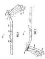
- FIG. 1is a radial side elevation of a right-hand volar plate according to the invention, shown with pegs coupled thereto;
- FIG. 2is an ulnar side elevation of a right-hand volar plate according to the invention, shown with pegs coupled thereto;
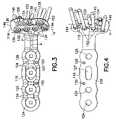
- FIG. 3is top view of a right-hand volar plate according to the invention, shown with pegs and screws;
- FIG. 4is bottom view of a right-hand volar plate according to the invention, shown with pegs coupled thereto;
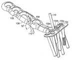
- FIG. 5is a perspective view of a right-hand volar plate according to the invention, shown with pegs coupled thereto and K-wires extending through body portion alignment holes and through proximal head alignment holes;
- FIG. 6is a front end view of a right-hand volar plate according to the invention, shown with pegs coupled thereto and K-wires extending through body portion alignment holes and proximal head alignment holes;
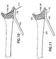
- FIGS. 7 through 12illustrate a method of performing an osteotomy of the distal radius according to the invention
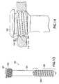
- FIG. 13is a side elevation of a partially threaded peg according to the invention.
- FIG. 14is a schematic illustration of a peg coupled within a peg hole
- FIG. 15is a broken volar view of the distal portion of a left-hand volar plate coupled on a volar side of a distal radius bone according to the invention.
- FIG. 16is a broken ulnar side view of the distal portion of a left hand volar plate coupled on a volar side of a distal radius bone according to the invention.
- the system 100is particularly adapted for aligning and stabilizing multiple bone fragments in a dorsally displaced distal radius fracture (or Colles' fracture).
- the system 100generally includes a substantially rigid T-shaped plate 102 , commonly called a volar plate, bone screws 104 ( FIG. 3 ), pegs 106 , 108 , and K-wires 110 ( FIGS. 5 and 6 ).
- Pegs 106have a threaded head and a non-threaded shaft
- pegs 108have both a threaded head and a threaded shaft.
- Either pegs 106 or 108 , or a combination thereofmay be used at the discretion of the surgeon. Exemplar pegs are described in more detail in U.S. Pat. No. 6,364,882, which is hereby incorporated by reference herein in its entirety.
- Peg 108includes a head portion 200 with preferably a single helical machine thread 202 of a first pitch and a shaft 204 portion having one or more threads 206 of a larger second pitch.
- the head portion of non-threaded shaft pegs 106also preferably includes a single helical thread.
- the threads 206preferably extend along a distal portion 208 of the shaft 204 , and most preferably where such distal portion comprises approximately one-half the length of the shaft.
- one or more pegsmay be used where the threads extend along substantially the entirety, or the entirety, or the length of the shaft.
- the volar plate 102 shown in FIGS. 1-6is a right-hand plate intended to be positioned against the volar side of a fractured radius bone of the right arm. It is appreciated that a left-hand volar plate (as shown in FIGS. 15 and 16 ) is substantially a mirror image of the plate shown and now described.
- the T-shaped plate 102defines an elongate body 116 , and a head 118 angled upward (in the Z-direction) relative to the body.
- the angle ⁇ in the Z-direction between the head 118 and the body 116is preferably approximately 25°.
- the head 118includes a distal buttress 120 (i.e., the portion of the head distal a first set of peg holes 134 , discussed below), which tapers in thickness toward a distal edge 121 .
- the thickest portion of the plate 102has a thickness of preferably approximately 0.1 inch (2.5 mm), and is preferably made from a titanium alloy, such as Ti-6Al-4V.
- the body 116includes four preferably countersunk screw holes 124 , 125 , 126 , 127 for the extension of bone screws 104 therethrough ( FIG. 2 ).
- One of the screw holes, 127is preferably generally oval in shape permitting longitudinal movement of the plate 102 relative to the shaft of a bone screw when the screw is not tightly clamped against the plate.
- the screw holesmay be any hole type for attaching a fixation structure, threaded or non-threaded, for coupling a cortical screw or a locking peg relative to the plate and the underlying bone.
- the head portion 118includes a proximal first set of threaded preferably cylindrical peg holes 134 (for placement of pegs 106 and/or 108 therein) and a relatively distal second set of threaded preferably cylindrical peg holes 138 (for placement of pegs 106 and/or 108 therein).
- the peg holes 134 , 138optionally have double lead internal threads 210 , 212 , with entries to these threads located 180° apart.
- Each of the threads 210 , 212is adapted to mate securely with the thread 202 on a peg head 200 , however thread 202 can only mate with one of the threads 210 , 212 at any one time.
- the depth of each of the double lead internal threads 210 , 212is preferably substantially less than the depth of thread 202 on peg head 200 , and most preferably approximately one half such depth.
- the double lead threads 210 , 212facilitate alignment and entry of the peg head thread 202 into a thread of the peg hole, as the peg will require rotation by at most 180° in a single rotational direction before thread engagement.
- the cylindrical double lead thread holedoes not compromise the secure interlock attained from full travel of the thread 202 of the peg head 200 through the cylindrical peg hole 134 , 138 through, e.g., 900°.
- the combination of double lead thread holes and a single helical thread on the peg headreduces cross-threading by fifty percent.
- the peg holes 134 of the first setare arranged substantially parallel to a line L 1 that is preferably slightly skewed (e.g., by 5°-10°) relative to a perpendicular P to the axis A of the body portion 116 .
- Axes through the respective centerlines of the first set of peg holes (indicated by the pegs 106 extending therethrough)are preferably oblique relative to each other, and are preferably angled relative to each other in two dimensions, generally as described in commonly-owned U.S. Pat. No. 6,364,882, which is hereby incorporated by reference herein in its entirety.
- the pegs 106are angled so as to extend through the subchondral bone just below and parallel to the curving articular surface of the distal radius so as to provide support for the central and/or dorsal aspects of the subchondral bone.
- This oblique orientation of the pegsoperates to stabilize the central and/or dorsal aspects of the subchondral bone of the articular surface relative to the head 118 of the plate 102 even where such pegs 106 do not have threaded shafts.
- the second set of peg holes 138is provided relatively distal of the first set of peg holes 134 and is most preferably primarily located in the tapered buttress 120 .
- Each of the peg holes 138preferably defines an axis that is oblique relative to the other of peg holes 136 and 138 .
- each and every peg 106 , 108 when positioned within respective peg holes 134 , 138defines a distinct axis relative to the other pegs.
- the axes of the peg holes 138are preferably oriented relative to the axes of peg holes 134 such that pegs 106 , 108 within peg holes 138 extend (or define axes which extend) between pegs (or axes thereof) within peg holes 134 in an interleaved manner and provide support for volar aspects of the subchondral bone of the distal radius.
- the oblique orientation of the pegsprovides such stabilization even where such pegs 106 do not have threaded shafts.
- the upper and lower surfaces 140 , 142 , respectively of the buttress 120are contoured relative to provide the least amount of interference with the anatomy.
- the lower surface 142is contoured for the anatomical structure of the radius bone 900 that it will overlie.
- the lower surface 142 at an ulnar-side portion 144 of the head portion 118is elevated primarily in a distal direction to accommodate the bulky volar rim 902 of the lunate fossa 904 (such volar rim commonly separating to become a volar marginal fragment in many fractures), and the lower surface at a radial side portion 146 of the head 118 is elevated laterally relative to the remainder of the head to accommodate a prominence 906 at the radial aspect of the radius bone, as indicated by the visibility of these lower surfaces in the side views of FIGS. 1 , 2 and 16 and the head-on view of FIG. 6 .
- the contoured shape(with generally three defined planes) provides a stable shape that prevents rocking of the plate on the bone.
- the upper and lower surfaces 140 , 142are contoured to present a reduced profile and therefore limit potential interference with the tendons and soft tissue near the edge of the articular surface.
- the buttress 120is tapered to prevent irritation of tendons and soft tissue extending over a boney ridge (referred to herein as ‘the watershed line’) and identified by dark line 910 on the volar side of the radius where the slope of the bone changes from ascending (up from the diaphysis 912 ) to descending (the distal articular portion 904 of the radius).
- the head 118 of the plate 102is contoured to seat at least partially within the concavity with the tapered buttress 120 terminating below the boney ridge so that the tendons and soft tissues can move over the boney ridge without any interference from the plate.
- the tapered edge 121 of the buttress 120tapers substantially from the bone contacting surface along the ulnar side of the buttress (with a relatively shallow change in slope from the proximal portion of the head to the distal edge of the buttress) and substantially tapers from the upper surface along the radial side (with a relatively steeper change in slope from the proximal portion of the head to the distal edge of the buttress).
- the distal edge 121 of the buttress 120defines ail elongate S-shape on a right-hand plate, an elongate Z-shape on a left-hand plate.
- a distal extension 148is also provided at the ulnar side portion 146 of the plate to further buttress the volar rim 902 of the articular socket of the radius bone, thereby providing support to maintain the wrist within the articular socket.
- Thisis contrary to prior art plates which, if they provide laterally asymmetrical support, provide such additional support on the radial side due to the apparent radial extension of the radius in view of the styloid process 914 .
- the styloid process 914is on the descending side of the boney ridge 910 (discussed above) and not suitable for buttressing.
- the styloid process 914is captured by one of the pegs.
- the radius bone 900 on the ascending sidehas an enlarged area at the ulnar side at the volar rim 902 which the distal extension 148 buttresses.
- the proximal portion of the head portion 118(rear of the buttress 120 to the proximal edge of the head portion) is approximately 5.3 mm deep, while the distal edge of the buttress is not straight so that the buttress has a varying proximal-distal depth.
- the buttressFrom a proximalmost location of the buttress 120 aligned with the radialmost hole of the first set of peg holes 134 the buttress has a proximal-distal depth of 2.28 mm (where the head portion rounds off), from a proximalmost location of the buttress aligned with the adjacent hole of the first set of peg holes the buttress has a proximal-distal depth of approximately 2.8 mm (along a straight portion substantially parallel to line L 1 ), from a proximalmost location of the buttress aligned with the adjacent hole thereof of the first set of peg holes the buttress has a proximal-distal depth of 3.56 mm (along an approach to the ulnar support), and from a proximalmost location of the buttress aligned with the ulnarly located hole of the first set of peg holes the buttress has a proximal-distal depth of 4.57 mm (at the distal extension 148
- the plate 102is provided with body alignment holes 150 and proximal head alignment holes 152 a , 152 b , 152 c (generally 152 ), each sized to ‘closely accept’ standard Kirschner wires (K-wires), e.g., 1.55 mm in diameter, in at least in dimension.
- K-wiresstandard Kirschner wires
- the K-wireis generally in a fixed angle relationship with the alignment hole such that there is preferably less than five degrees (5°) of relative angular movement therebetween, and more preferably less than three degrees (3°) of relative angular movement therebetween.
- the clearance between the K-wire and the alignment holeis preferably 0.002 inch, and more preferably 0.001 inch.
- the plate 102also includes a distal head alignment hole 154 is provided between the central and radial-side peg holes 138 , and preferably has a circular upper opening, and flares to a laterally oblong lower opening, as shown best in FIG. 6 .
- the alignment hole 154closely accepts a K-wire in a proximal-distal dimension and permits a degree of angular movement relative thereto in a lateral dimension (preferably approximately 30°).
- the upper openingcan be oblong and the lower opening circular.
- alignment hole 154can be laterally oblong at upper and lower portions or throughout, but proximally-distally dimensioned to closely receive a K-wire.
- the distal head alignment hole 154has specialized application in the correction of metaphyseal deformities, as described in more detail below.
- the upper openings of all the alignment holes 150 , 152 , 154are substantially smaller in diameter (e.g., by thirty to fifty percent) than the shafts of screws 104 (approximately 3.15 mm in diameter) and the shafts of pegs 106 , 108 (approximately 2.25 mm in diameter).
- the body alignment holes 150are longitudinally displaced along the body portion 116 and provided at an oblique angle (preferably approximately 15°, as shown in FIG. 5 ) relative to a line normal relative to the lower surface 158 of the body portion 116 .
- the body alignment holes 150may be oblong in the transverse direction but fixed angle in the longitudinal direction. This enables the surgeon to drill perpendicular to the bone surface.
- the proximal head alignment holes 152alternate with the peg holes 134 .
- a tangent line H to the distalmost points of the head alignment holes 152is preferably substantially coincident or closely parallel with a line tangent to points on the circumferences of the shafts of pegs 106 inserted through holes 134 adjacent the head portion 118 of the plate 102 .
- a shaft 106 a of a pegis generally smaller in diameter than a head 106 b of a peg ( FIG. 6 ).
- a line tangent to the peg holes 134(each sized for receiving the head 106 b of peg 106 ) will be closely located, but parallel, to a line tangent to a distalmost point on the respective alignment hole 152 .
- a tangent linewhich is preferably substantially coincident with a line tangent to points on the circumferences of the shafts of pegs and (ii) a tangent line to a set of peg holes shall be considered to be “substantially coincident” with a line tangent to a distalmost point of an alignment hole 152 .
- Axes through the centerlines of alignment holes 152preferably generally approximate (within, e.g., 3-5°) the angle of an axis of an adjacent peg hole 134 .
- the axis through each proximal alignment hole 152is preferably oriented substantially equidistantly between the axes through peg holes 134 on either side of the alignment hole.
- K-wires 110 inserted into the proximal alignment holes 152(and extending coaxial with the axes therethrough) define a virtual surface (i.e., three dimensional surface) which approximately substantially the same virtual surface (i.e., three dimensional surface) defined by pegs 106 , 108 inserted through peg holes 134 .
- the plate 102may be used in at least two different applications: fracture fixation and metaphyseal osteotomies.
- fracture fixationan incision is first made over the distal radius, and the pronator quadratus is reflected from its radial insertion exposing the entire distal radius ulnarly to the distal radioulnar joint.
- the surgeonreduces the fracture and aligns the plate 102 thereover.
- the surgeonthen either attaches the plate to the proximal fragment with a screw or drills one or two K-wires 110 through respective body alignment holes 150 , and one or more K-wires through selected proximal head alignment holes 152 at the location at which the surgeon believes the pegs 106 , 108 should be placed based on anatomical landmarks and/or fluoroscopic guidance.
- the K-wirestemporarily fix the orientation of the plate to the distal fragment. While the fixation is temporary, it is relatively secure in view of the fact that the body alignment holes 150 , proximal head alignment holes 152 , and K-wires 110 therethrough are angled in different orientations relative to the lower surface of the plate.
- the K-wires 110not only fix the plate 102 to the bone, but also prevent angular displacement of bone fragments. Once the alignment is so fixed, the fracture is examined, e.g., under fluoroscopy, to determine whether the K-wires 110 are properly aligned relative to the articular surface. As the axes of the proximal head alignment holes 152 correspond to axes of the adjacent peg holes 134 , the fluoroscopically viewed K-wires 110 anticipate whether the pegs 106 , 108 will be properly oriented.
- the K-wires 110maintain the position of the plate 102 over the fracture while holes in the bone are drilled through the screw holes 124 , 125 , 126 , 127 for the screws 104 and peg holes 134 , 138 for pegs 106 , 108 , with confidence that the locations and orientation of the screws and pegs inserted therein are anatomically appropriate.
- the K-wires 110can be removed and the surgeon has an opportunity to relocate and/or reorient the K-wires and drill again. Since each K-wire is of relatively small diameter, the bone is not significantly damaged by the drilling process and the surgeon is not committed to the initial drill location and/or orientation.
- the pegs 106 within the pegs holes 134define projections that provide support at the central and/or dorsal aspects of the subchondral bone.
- the pegs 106 within peg holes 138define projections that provide support at the volar aspect behind the articular surface of the bone surface.
- the sets of pegs 106 , 108 through peg holes 134 , 138laterally overlap so that the pegs preferably laterally alternate to provide closely-spaced tangential cradling of the subchondral bone.
- a preferred degree of subchondral supportis provided with four peg holes 134 (and associated pegs) through the proximal portion of the head 118 of the plate, and three peg holes 138 (and associated pegs) through the distal portion of the head 118 .
- the fracture fixation systemthereby defines a framework which substantially tangentially supports the bone fragments in their proper orientation.
- suitable supportmay also be provided where the pegs 106 and 108 are parallel to each other or in another relative orientation or with fewer peg holes and/or pegs.
- the methodparticularly facilitates stabilization of a metaphyseal fracture which may include a smaller distal bone fragment spaced apart from a larger proximal fragment.
- a metaphyseal fracturewhich may include a smaller distal bone fragment spaced apart from a larger proximal fragment.
- the insertion of one or more threaded pegs 108 (preferably in conjunction with several non-threaded pegs 106 ) in which the threads on the shaft 206 have a pitch greater than the threads 202 on the head 200causes a limited amount of compression of the smaller distal bone fragment toward the larger proximal bone fragment, and thus toward the plate.
- the platemay be used in an osteotomy to correct a metaphyseal deformity 200 (such as malformed fracture or congenital deformity), as shown in FIG. 7 .
- a K-wire 110is drilled into the bone parallel to the articular surface S in the lateral view under fluoroscopy ( FIG. 8 ).
- the free end of the K-wire 110is guided through the oblong distal head alignment hole 154 , and the plate 102 is slid down over the K-wire into position against the bone ( FIG. 9 ).
- the oblong alignment hole 154permits the plate 102 to tilt laterally over the K-wire 110 to sit flat on the bone, but does not permit tilting of plate relative to the K-wire in the anterior-posterior (sagital) plane. This is important, as visualization to align the K-wire parallel relative to the articular surface will not disclose whether the K-wire is angled in the lateral direction. Thus, the plate is brought over the K-wire in the correct anterior-posterior alignment, but may then be laterally titled on the K-wire to effect proper medial-lateral placement of the plate on bone. Once the plate 102 is seated against the bone, the surgeon drills holes in the bone in aligmnent with the peg holes 134 , 138 ( FIG.
- pegsWhile fixed single-angle pegs have been disclosed for use with the plate (i.e., the pegs may be fixed in respective threaded peg holes 134 , 136 only coaxial with an axis defined by the respective peg holes), it is appreciated that an articulating peg system, such as that disclosed in co-owned U.S. Pat. No. 6,440,135 or co-owned and co-pending U.S. Ser. No. 10/159,612, both of which are hereby incorporated by reference herein in their entireties, may also be used. In such articulating peg systems, the peg holes and pegs are structurally adapted such that individual pegs may be fixed at any angle within a range of angles.
- one or both sets of the pegsmay be replaced by preferably blunt tines which are integrated into the plate such that the plate and tines are unitary in construct.
- other elongate projectionsmay be coupled to the plate to define the desired support.
- fixation plateand particularly plates for fixation of distal radius fractures, as well as a method of aligning and stabilizing a distal radius fracture and performing an osteotomy. While particular embodiments of the invention have been described, it is not intended that the invention be limited thereto, as it is intended that the invention be as broad in scope as the art will allow and that the specification be read likewise. Thus, while particular preferred materials, dimensions, and relative angles for particular elements of the system have been disclosed, it will be appreciated that other materials, dimensions, and relative angles may be used as well.
- plates having shapes other than a ‘T’may also be used, such as lateral and medial columns (generally ‘L’-shaped), and plates having a flared head, provided such plates are dimensioned and configured for placement at the distal radius.
- Lmedial columns
- plates having a flared headprovided such plates are dimensioned and configured for placement at the distal radius.
- screw holes in the volar plate and bone screwshave been described, it will be understood another number of screw holes and screws may be used. Further, fewer screws than the number of screw holes may be used to secure to the plate to the bone.
- peg holes and bone pegsmay be used, preferably such that at least two pegs angled in two dimensions relative to each other are provided.
- other anglescan also be used.
- cylindrical double lead thread hole and single thread head interfacehas been disclosed with respect to a fracture plate for distal radius fractures, it is appreciated that such a system has advantage to other orthopedic stabilization devices such as fragment plates (which may be rectangular in shape or a different shape) and plates specifically designed for fractures of other bones.
- a threaded pegi.e., locking screw
- threads of different pitches on the head and along the shaftmay also be used in other applications.
- a double lead threadis preferred for use with a peg having a single thread on its head, it is appreciated that, e.g., a triple lead thread can be used where the entry leads are angularly offset by 120°. Such will reduce cross threading by two-thirds, but will also reduce hole thread depth further. It will therefore be appreciated by those skilled in the art that yet other modifications could be made to the provided invention without deviating from its spirit and scope.
Landscapes
- Health & Medical Sciences (AREA)
- Orthopedic Medicine & Surgery (AREA)
- Surgery (AREA)
- Life Sciences & Earth Sciences (AREA)
- Heart & Thoracic Surgery (AREA)
- Nuclear Medicine, Radiotherapy & Molecular Imaging (AREA)
- Engineering & Computer Science (AREA)
- Biomedical Technology (AREA)
- Neurology (AREA)
- Medical Informatics (AREA)
- Molecular Biology (AREA)
- Animal Behavior & Ethology (AREA)
- General Health & Medical Sciences (AREA)
- Public Health (AREA)
- Veterinary Medicine (AREA)
- Surgical Instruments (AREA)
Abstract
Description
Claims (15)
Priority Applications (3)
| Application Number | Priority Date | Filing Date | Title |
|---|---|---|---|
| US10/985,598US7635381B2 (en) | 2003-03-27 | 2004-11-10 | Anatomical distal radius fracture fixation plate with fixed-angle K-wire holes defining a three-dimensional surface |
| US14/295,808US9526543B2 (en) | 2004-11-10 | 2014-06-04 | Modular fracture fixation system |
| US15/364,505US9913671B2 (en) | 2004-11-10 | 2016-11-30 | Modular fracture fixation system |
Applications Claiming Priority (4)
| Application Number | Priority Date | Filing Date | Title |
|---|---|---|---|
| US10/401,089US6866665B2 (en) | 2003-03-27 | 2003-03-27 | Bone fracture fixation system with subchondral and articular surface support |
| US10/664,371US7857838B2 (en) | 2003-03-27 | 2003-09-17 | Anatomical distal radius fracture fixation plate |
| US10/689,797US7282053B2 (en) | 2003-03-27 | 2003-10-21 | Method of using fracture fixation plate for performing osteotomy |
| US10/985,598US7635381B2 (en) | 2003-03-27 | 2004-11-10 | Anatomical distal radius fracture fixation plate with fixed-angle K-wire holes defining a three-dimensional surface |
Related Parent Applications (1)
| Application Number | Title | Priority Date | Filing Date |
|---|---|---|---|
| US10/689,797Continuation-In-PartUS7282053B2 (en) | 2000-02-01 | 2003-10-21 | Method of using fracture fixation plate for performing osteotomy |
Publications (2)
| Publication Number | Publication Date |
|---|---|
| US20050065524A1 US20050065524A1 (en) | 2005-03-24 |
| US7635381B2true US7635381B2 (en) | 2009-12-22 |
Family
ID=46303259
Family Applications (1)
| Application Number | Title | Priority Date | Filing Date |
|---|---|---|---|
| US10/985,598Expired - LifetimeUS7635381B2 (en) | 2003-03-27 | 2004-11-10 | Anatomical distal radius fracture fixation plate with fixed-angle K-wire holes defining a three-dimensional surface |
Country Status (1)
| Country | Link |
|---|---|
| US (1) | US7635381B2 (en) |
Cited By (64)
| Publication number | Priority date | Publication date | Assignee | Title |
|---|---|---|---|---|
| WO2006102081A1 (en) | 2005-03-17 | 2006-09-28 | Depuy Products, Inc. | Modular fracture fixation plate system |
| US20070055253A1 (en)* | 2005-03-17 | 2007-03-08 | Orbay Jorge L | Modular Fracture Fixation System |
| US20070233115A1 (en)* | 2006-03-17 | 2007-10-04 | Robert Sixto | Bone Plate with Variable Torsional Stiffness at Fixed Angle Holes |
| US20100069966A1 (en)* | 2008-09-15 | 2010-03-18 | Alfredo Castaneda | Bone Plate System for Hand Fractures and Other Small Bones |
| US20110152948A1 (en)* | 2009-06-19 | 2011-06-23 | David Crook | Triple lead bone screw |
| US8419776B2 (en) | 2010-03-08 | 2013-04-16 | Memometal Technologies | Radius-plate assembly |
| US8425575B2 (en) | 2010-09-27 | 2013-04-23 | Acumed Llc | Bone plate supported by a leg member and used as a lever |
| US8579898B2 (en) | 2010-03-08 | 2013-11-12 | Memometal Technologies | Adjustable-angle radius plate |
| US8591554B2 (en) | 2010-05-07 | 2013-11-26 | Osteomed Llc | System for treating bone fractures |
| US8814918B2 (en) | 2011-02-14 | 2014-08-26 | Skeletal Dynamics, L.L.C. | Fracture fixation plate |
| US9131969B2 (en) | 2011-06-30 | 2015-09-15 | Morgan Packard Lorio | Spinal plate and method for using same |
| US20160278824A1 (en)* | 2015-03-25 | 2016-09-29 | Medartis Holding Ag | Method for treating fractures of a bone |
| US9468479B2 (en) | 2013-09-06 | 2016-10-18 | Cardinal Health 247, Inc. | Bone plate |
| US9510880B2 (en) | 2013-08-13 | 2016-12-06 | Zimmer, Inc. | Polyaxial locking mechanism |
| US20170027627A1 (en)* | 2014-04-18 | 2017-02-02 | Hae Sun Paik | Fixing tool for open-wedge high tibial osteotomy |
| US9833270B2 (en) | 2013-09-19 | 2017-12-05 | Mcginley Engineered Solutions, Llc | Variable angle blade plate system and method |
| US9907582B1 (en) | 2011-04-25 | 2018-03-06 | Nuvasive, Inc. | Minimally invasive spinal fixation system and related methods |
| US10231768B2 (en) | 2003-05-30 | 2019-03-19 | DePuy Synthes Products, Inc. | Methods for implanting bone plates |
| US10335211B2 (en) | 2004-01-26 | 2019-07-02 | DePuy Synthes Products, Inc. | Highly-versatile variable-angle bone plate system |
| US10342586B2 (en) | 2003-08-26 | 2019-07-09 | DePuy Synthes Products, Inc. | Bone plate |
| US10368928B2 (en) | 2017-03-13 | 2019-08-06 | Globus Medical, Inc. | Bone stabilization systems |
| US10383668B2 (en) | 2016-08-17 | 2019-08-20 | Globus Medical, Inc. | Volar distal radius stabilization system |
| US10420596B2 (en) | 2016-08-17 | 2019-09-24 | Globus Medical, Inc. | Volar distal radius stabilization system |
| US10575884B2 (en) | 2016-08-17 | 2020-03-03 | Globus Medical, Inc. | Fracture plates, systems, and methods |
| US10624686B2 (en) | 2016-09-08 | 2020-04-21 | DePuy Synthes Products, Inc. | Variable angel bone plate |
| US10631903B2 (en) | 2017-03-10 | 2020-04-28 | Globus Medical Inc. | Clavicle fixation system |
| US10687874B2 (en) | 2015-08-27 | 2020-06-23 | Globus Medical, Inc | Proximal humeral stabilization system |
| US10687873B2 (en) | 2016-08-17 | 2020-06-23 | Globus Medical Inc. | Stabilization systems |
| US10751098B2 (en) | 2016-08-17 | 2020-08-25 | Globus Medical Inc. | Stabilization systems |
| US10772665B2 (en) | 2018-03-29 | 2020-09-15 | DePuy Synthes Products, Inc. | Locking structures for affixing bone anchors to a bone plate, and related systems and methods |
| US10820930B2 (en) | 2016-09-08 | 2020-11-03 | DePuy Synthes Products, Inc. | Variable angle bone plate |
| US10828074B2 (en) | 2015-11-20 | 2020-11-10 | Globus Medical, Inc. | Expandalbe intramedullary systems and methods of using the same |
| US10828075B2 (en) | 2015-09-25 | 2020-11-10 | Globus Medical Inc. | Bone fixation devices having a locking feature |
| US10856920B2 (en) | 2017-09-13 | 2020-12-08 | Globus Medical Inc. | Bone stabilization systems |
| US10905477B2 (en) | 2017-03-13 | 2021-02-02 | Globus Medical, Inc. | Bone stabilization systems |
| US10905476B2 (en) | 2016-09-08 | 2021-02-02 | DePuy Synthes Products, Inc. | Variable angle bone plate |
| US10925651B2 (en) | 2018-12-21 | 2021-02-23 | DePuy Synthes Products, Inc. | Implant having locking holes with collection cavity for shavings |
| US11013541B2 (en) | 2018-04-30 | 2021-05-25 | DePuy Synthes Products, Inc. | Threaded locking structures for affixing bone anchors to a bone plate, and related systems and methods |
| US11026727B2 (en) | 2018-03-20 | 2021-06-08 | DePuy Synthes Products, Inc. | Bone plate with form-fitting variable-angle locking hole |
| US11071570B2 (en) | 2018-03-02 | 2021-07-27 | Globus Medical, Inc. | Distal tibial plating system |
| US11076898B2 (en) | 2015-08-27 | 2021-08-03 | Globus Medical, Inc. | Proximal humeral stabilization system |
| US11096730B2 (en) | 2017-09-13 | 2021-08-24 | Globus Medical Inc. | Bone stabilization systems |
| US11129627B2 (en) | 2019-10-30 | 2021-09-28 | Globus Medical, Inc. | Method and apparatus for inserting a bone plate |
| US11141172B2 (en) | 2018-04-11 | 2021-10-12 | Globus Medical, Inc. | Method and apparatus for locking a drill guide in a polyaxial hole |
| US11141204B2 (en) | 2016-08-17 | 2021-10-12 | Globus Medical Inc. | Wrist stabilization systems |
| US11197701B2 (en) | 2016-08-17 | 2021-12-14 | Globus Medical, Inc. | Stabilization systems |
| US11197682B2 (en) | 2015-08-27 | 2021-12-14 | Globus Medical, Inc. | Proximal humeral stabilization system |
| US11197704B2 (en) | 2016-04-19 | 2021-12-14 | Globus Medical, Inc. | Implantable compression screws |
| US11202663B2 (en) | 2019-02-13 | 2021-12-21 | Globus Medical, Inc. | Proximal humeral stabilization systems and methods thereof |
| US11213327B2 (en) | 2016-08-17 | 2022-01-04 | Globus Medical, Inc. | Fracture plates, systems, and methods |
| US11219527B2 (en) | 2011-02-16 | 2022-01-11 | Genesis Medical Devices Llc | Combination intra-medullary and extra-medullary fracture stabilization with aligning arm |
| US11224468B2 (en) | 2018-03-02 | 2022-01-18 | Globus Medical, Inc. | Distal tibial plating system |
| US11259851B2 (en) | 2003-08-26 | 2022-03-01 | DePuy Synthes Products, Inc. | Bone plate |
| US11284920B2 (en) | 2016-03-02 | 2022-03-29 | Globus Medical Inc. | Fixators for bone stabilization and associated systems and methods |
| US11291484B2 (en) | 2004-01-26 | 2022-04-05 | DePuy Synthes Products, Inc. | Highly-versatile variable-angle bone plate system |
| US11331128B2 (en) | 2016-08-17 | 2022-05-17 | Globus Medical Inc. | Distal radius stabilization system |
| US11337740B2 (en) | 2020-04-29 | 2022-05-24 | OsteoCertus, LLC | Bone plate and method for use in a tibial plateau leveling osteotomy (TPLO) |
| US11337739B2 (en) | 2017-12-20 | 2022-05-24 | Glabs X, Llc | Multiplanar fixation plate for fracture repair |
| US11432857B2 (en) | 2016-08-17 | 2022-09-06 | Globus Medical, Inc. | Stabilization systems |
| US11723647B2 (en) | 2019-12-17 | 2023-08-15 | Globus Medical, Inc. | Syndesmosis fixation assembly |
| US12042200B2 (en) | 2016-09-22 | 2024-07-23 | Globus Medical, Inc. | Systems and methods for intramedullary nail implantation |
| US12064150B2 (en) | 2022-01-19 | 2024-08-20 | Globus Medical Inc. | System and method for treating bone fractures |
| US12185995B2 (en) | 2019-10-09 | 2025-01-07 | Globus Medical, Inc. | Bone stabilization systems |
| US12279795B2 (en) | 2017-09-13 | 2025-04-22 | Globus Medical, Inc. | Bone stabilization systems |
Families Citing this family (45)
| Publication number | Priority date | Publication date | Assignee | Title |
|---|---|---|---|---|
| US7857838B2 (en) | 2003-03-27 | 2010-12-28 | Depuy Products, Inc. | Anatomical distal radius fracture fixation plate |
| US7537604B2 (en)* | 2002-11-19 | 2009-05-26 | Acumed Llc | Bone plates with slots |
| US20050234458A1 (en)* | 2004-04-19 | 2005-10-20 | Huebner Randall J | Expanded stabilization of bones |
| US20050240187A1 (en)* | 2004-04-22 | 2005-10-27 | Huebner Randall J | Expanded fixation of bones |
| US7717945B2 (en)* | 2002-07-22 | 2010-05-18 | Acumed Llc | Orthopedic systems |
| US7326212B2 (en)* | 2002-11-19 | 2008-02-05 | Acumed Llc | Bone plates with reference marks |
| US20040116930A1 (en)* | 2002-06-10 | 2004-06-17 | O'driscoll Shawn W. | Bone plates |
| US20050171544A1 (en)* | 2004-02-02 | 2005-08-04 | Acumed Llc | Bone plate with toothed aperture |
| CN1309352C (en)* | 2002-07-22 | 2007-04-11 | 精密医疗责任有限公司 | Bone fusion system |
| AU2003294342A1 (en)* | 2002-11-19 | 2004-06-15 | Acumed Llc | Guide system for bone-repair devices |
| AU2003294414B2 (en)* | 2002-11-19 | 2009-03-12 | Acumed Llc | Deformable bone plates |
| US7722653B2 (en)* | 2003-03-26 | 2010-05-25 | Greatbatch Medical S.A. | Locking bone plate |
| BRPI0408769A (en)* | 2003-03-26 | 2006-03-28 | Swiss Orthopedic Solutions Sa | lock bone plate |
| WO2004112587A2 (en)* | 2003-06-20 | 2004-12-29 | Acumed Llc | Bone plates with intraoperatively tapped apertures |
| US20050131413A1 (en)* | 2003-06-20 | 2005-06-16 | O'driscoll Shawn W. | Bone plate with interference fit screw |
| US7635365B2 (en) | 2003-08-28 | 2009-12-22 | Ellis Thomas J | Bone plates |
| US20050085818A1 (en)* | 2003-10-17 | 2005-04-21 | Huebner Randall J. | Systems for distal radius fixation |
| CA2546050C (en)* | 2003-11-18 | 2012-08-28 | Synthes Gmbh | Osteosynthesis plate set |
| WO2006091827A2 (en)* | 2005-02-25 | 2006-08-31 | Regents Of The University Of California | Device and template for canine humeral slide osteotomy |
| WO2005102193A2 (en)* | 2004-04-19 | 2005-11-03 | Acumed, Llc | Placement of fasteners into bone |
| US7137987B2 (en) | 2004-07-02 | 2006-11-21 | Wright Medical Technology, Inc. | Distal radius bone plating system with locking and non-locking screws |
| CA2596266C (en) | 2005-01-28 | 2015-03-31 | Depuy Products, Inc. | Nail plate system |
| US8177818B2 (en) | 2005-09-08 | 2012-05-15 | Securos, Inc. | Fixation plate |
| US7699880B2 (en) | 2005-10-24 | 2010-04-20 | Depuy Products, Inc. | Bone fixation system and bone screws having anti-back out feature |
| US8398687B2 (en)* | 2006-12-06 | 2013-03-19 | Amei Technologies, Inc. | Volar plate fixation device |
| CA2781407A1 (en) | 2008-01-14 | 2009-07-23 | Michael P. Brenzel | Apparatus and methods for fracture repair |
| US9237910B2 (en) | 2012-01-26 | 2016-01-19 | Acute Innovations Llc | Clip for rib stabilization |
| US12285197B2 (en) | 2008-10-10 | 2025-04-29 | Acumed Llc | Bone fixation system with opposed mounting portions |
| US20100168799A1 (en)* | 2008-12-29 | 2010-07-01 | Schumer Evan D | Ulnar osteotomy plate including increased compression |
| US8496692B2 (en)* | 2009-09-21 | 2013-07-30 | Jmea Corporation | Locking securing member |
| JP2013512042A (en)* | 2009-11-27 | 2013-04-11 | シンセス ゲゼルシャフト ミット ベシュレンクテル ハフツング | Planar fixation concept for distal radius fractures |
| US8568417B2 (en) | 2009-12-18 | 2013-10-29 | Charles River Engineering Solutions And Technologies, Llc | Articulating tool and methods of using |
| US20110178520A1 (en) | 2010-01-15 | 2011-07-21 | Kyle Taylor | Rotary-rigid orthopaedic rod |
| WO2011091052A1 (en) | 2010-01-20 | 2011-07-28 | Kyle Taylor | Apparatus and methods for bone access and cavity preparation |
| US20110218580A1 (en)* | 2010-03-08 | 2011-09-08 | Stryker Trauma Sa | Bone fixation system with curved profile threads |
| WO2011112615A1 (en) | 2010-03-08 | 2011-09-15 | Krinke Todd A | Apparatus and methods for securing a bone implant |
| WO2012050424A1 (en)* | 2010-10-14 | 2012-04-19 | Sai Yeong Leong | A distal radius plating system |
| CN102429714B (en)* | 2011-08-15 | 2015-04-15 | 谢友军 | Distal end radius fracture plate |
| WO2013036362A1 (en) | 2011-09-06 | 2013-03-14 | Synthes Usa, Llc | Pancarpal arthrodesis bone plate |
| WO2013049849A2 (en)* | 2011-09-30 | 2013-04-04 | Acute Innovations, Llc, An Oregon Limited Liability Company | Bone fixation system with opposed mounting portions |
| CN105939677A (en) | 2013-12-12 | 2016-09-14 | 康文图斯整形外科公司 | Tissue displacement tools and methods |
| EP3164093B1 (en) | 2014-07-03 | 2024-02-14 | Acumed LLC | Bone plate with movable joint |
| EP3226788B1 (en)* | 2014-12-04 | 2020-01-29 | Orthofix S.r.l. | Orthopedic external fixation system for the treatment of complex fractures under precarious surgical environmental conditions |
| CN106963468B (en)* | 2017-04-18 | 2023-08-29 | 中国人民解放军总医院 | Child epiphyseal plate damage fixing device |
| WO2019010252A2 (en) | 2017-07-04 | 2019-01-10 | Conventus Orthopaedics, Inc. | APPARATUS AND METHODS FOR TREATING BONES |
Citations (58)
| Publication number | Priority date | Publication date | Assignee | Title |
|---|---|---|---|---|
| US2526959A (en) | 1947-07-01 | 1950-10-24 | Frank A Lorenzo | Fracture reduction apparatus |
| US3561437A (en) | 1967-11-08 | 1971-02-09 | Jose Luis Orlich | Apparatus for fixing fractures of the femur |
| US3741205A (en) | 1971-06-14 | 1973-06-26 | K Markolf | Bone fixation plate |
| US4506662A (en) | 1981-06-18 | 1985-03-26 | Mecron Medizinische Produkte Gmbh | Nail for fixing a fracture of the femur |
| US4565193A (en) | 1982-09-13 | 1986-01-21 | Elke Streli | Pronged plate for resetting fractured bones |
| US4794919A (en) | 1986-01-31 | 1989-01-03 | Nilsson John S | Fixating device |
| US4800874A (en)* | 1986-07-15 | 1989-01-31 | Vereinigte Edelstahlwerke A.G. | Anatomical bone plate and/or transfixion plate |
| US4867144A (en) | 1986-04-14 | 1989-09-19 | Huta Baildon | Plate for connecting base splinters with bone shafts |
| US5006120A (en) | 1989-10-10 | 1991-04-09 | Carter Peter R | Distal radial fracture set and method for repairing distal radial fractures |
| US5015248A (en)* | 1990-06-11 | 1991-05-14 | New York Society For The Relief Of The Ruptured & Crippled, Maintaining The Hospital For Special Surgery | Bone fracture fixation device |
| US5151103A (en) | 1987-11-03 | 1992-09-29 | Synthes (U.S.A.) | Point contact bone compression plate |
| US5197966A (en)* | 1992-05-22 | 1993-03-30 | Sommerkamp T Greg | Radiodorsal buttress blade plate implant for repairing distal radius fractures |
| US5304180A (en) | 1992-01-17 | 1994-04-19 | Slocum D Barclay | Tibial osteotomy fixation plate |
| US5462547A (en) | 1991-05-30 | 1995-10-31 | Synthes (U.S.A.) | Trochanter stabilization device |
| US5527311A (en)* | 1991-11-13 | 1996-06-18 | Howmedica Gmbh | Support for the human spine |
| US5586985A (en)* | 1994-10-26 | 1996-12-24 | Regents Of The University Of Minnesota | Method and apparatus for fixation of distal radius fractures |
| US5601553A (en)* | 1994-10-03 | 1997-02-11 | Synthes (U.S.A.) | Locking plate and bone screw |
| US5616144A (en) | 1992-11-25 | 1997-04-01 | Codman & Shurtleff, Inc. | Osteosynthesis plate system |
| US5665088A (en) | 1993-10-06 | 1997-09-09 | Smith & Nephew Richards Inc. | Bone section reattachment apparatus and method |
| US5676667A (en) | 1995-12-08 | 1997-10-14 | Hausman; Michael | Bone fixation apparatus and method |
| US5709682A (en) | 1994-11-30 | 1998-01-20 | Medoff; Robert J. | Surgical clamp for fixation of bone fragments |
| US5709686A (en) | 1995-03-27 | 1998-01-20 | Synthes (U.S.A.) | Bone plate |
| US5718705A (en) | 1996-07-16 | 1998-02-17 | Sammarco; Giacomo J. | Internal fixation plate |
| US5749872A (en) | 1995-09-08 | 1998-05-12 | Ace Medical Company | Keyed/keyless barrel for bone plates |
| US5772662A (en) | 1986-06-23 | 1998-06-30 | Howmedica Inc. | Femoral fixation system |
| US5853413A (en) | 1997-04-18 | 1998-12-29 | Bristol-Myers Squibb Company | Wrist fusion plate |
| US5931839A (en) | 1995-01-27 | 1999-08-03 | Medoff; Robert J. | Pin plate for fixation of bone fractures |
| US5938664A (en) | 1998-03-31 | 1999-08-17 | Zimmer, Inc. | Orthopaedic bone plate |
| US5941878A (en) | 1995-02-14 | 1999-08-24 | Medoff; Robert J. | Implantable, surgical buttressing device |
| US5968047A (en) | 1996-04-05 | 1999-10-19 | Reed; Thomas Mills | Fixation devices |
| US6093201A (en) | 1999-01-19 | 2000-07-25 | Ethicon, Inc. | Biocompatible absorbable polymer plating system for tissue fixation |
| US6096040A (en) | 1996-06-14 | 2000-08-01 | Depuy Ace Medical Company | Upper extremity bone plates |
| US6221073B1 (en) | 1999-08-20 | 2001-04-24 | Kinetikos Medical, Inc. | Wrist fusion apparatus and method |
| USD443060S1 (en) | 2000-06-01 | 2001-05-29 | Bristol-Myers Squibb Company | Bone plate |
| US20010011172A1 (en) | 2000-02-01 | 2001-08-02 | Hand Innovations, Inc. | Volar fixation system with articulating stabilization pegs |
| US6270499B1 (en) | 1997-10-20 | 2001-08-07 | Synthes (U.S.A.) | Bone fixation device |
| US6283969B1 (en) | 2000-03-10 | 2001-09-04 | Wright Medical Technology, Inc. | Bone plating system |
| US6355041B1 (en) | 2001-01-30 | 2002-03-12 | Board Of Supervisors Of Louisiana State University And Agricultural And Mechanical College | Bone pin-plate surgical device and method for promoting athrodesis of the equine fetlock joint |
| US20020032446A1 (en)* | 2000-02-01 | 2002-03-14 | Orbay Jorge L. | Fixation plate system for dorsal wrist fracture fixation |
| US6358250B1 (en)* | 2000-02-01 | 2002-03-19 | Hand Innovations, Inc. | Volar fixation system |
| US6379359B1 (en) | 2000-05-05 | 2002-04-30 | University Of North Carolina At Chapel Hill | Percutaneous intrafocal plate system |
| US6468278B1 (en) | 1997-11-14 | 2002-10-22 | Medos Medizintechnik Gmbh | Implant for the stabilization of a fracture |
| US20020156474A1 (en) | 2001-04-20 | 2002-10-24 | Michael Wack | Polyaxial locking plate |
| WO2002096309A1 (en) | 2001-05-28 | 2002-12-05 | Synthes Ag Chur | Bone plate for the fixation of fractures of the proximal humerus |
| US6508819B1 (en) | 2001-08-28 | 2003-01-21 | Hand Innovations, Inc. | Method of dorsal wrist fracture fixation |
| US6527775B1 (en) | 2000-09-22 | 2003-03-04 | Piper Medical, Inc. | Intramedullary interlocking fixation device for the distal radius |
| US20030073999A1 (en) | 2001-10-12 | 2003-04-17 | Putnam Matthew D. | Intramedullary rod for wrist fixation |
| US20030105461A1 (en) | 2001-11-30 | 2003-06-05 | Putnam Matthew D. | Wrist surgery devices and techniques |
| US20030153918A1 (en) | 2002-02-14 | 2003-08-14 | Putnam Matthew D. | Volar fixation plate |
| US6623486B1 (en) | 1999-09-13 | 2003-09-23 | Synthes (U.S.A.) | bone plating system |
| US20040097937A1 (en) | 2002-11-19 | 2004-05-20 | Sandi Pike | Orthopedic bone plate |
| US6767351B2 (en) | 2000-02-01 | 2004-07-27 | Hand Innovations, Inc. | Fixation system with multidirectional stabilization pegs |
| US6821278B2 (en)* | 2000-06-26 | 2004-11-23 | Synthes Ag Chur | Bone plate |
| US20050010226A1 (en) | 2003-05-30 | 2005-01-13 | Grady Mark P. | Bone plate |
| US6866665B2 (en) | 2003-03-27 | 2005-03-15 | Hand Innovations, Llc | Bone fracture fixation system with subchondral and articular surface support |
| US20050085818A1 (en) | 2003-10-17 | 2005-04-21 | Huebner Randall J. | Systems for distal radius fixation |
| US7044951B2 (en) | 2001-02-12 | 2006-05-16 | Robert J. Medoff | Fracture fixation device in which a fixation pin is axially restrained |
| US7090676B2 (en) | 2002-11-19 | 2006-08-15 | Acumed Llc | Adjustable bone plates |
- 2004
- 2004-11-10USUS10/985,598patent/US7635381B2/ennot_activeExpired - Lifetime
Patent Citations (66)
| Publication number | Priority date | Publication date | Assignee | Title |
|---|---|---|---|---|
| US2526959A (en) | 1947-07-01 | 1950-10-24 | Frank A Lorenzo | Fracture reduction apparatus |
| US3561437A (en) | 1967-11-08 | 1971-02-09 | Jose Luis Orlich | Apparatus for fixing fractures of the femur |
| US3741205A (en) | 1971-06-14 | 1973-06-26 | K Markolf | Bone fixation plate |
| US4506662A (en) | 1981-06-18 | 1985-03-26 | Mecron Medizinische Produkte Gmbh | Nail for fixing a fracture of the femur |
| US4565193A (en) | 1982-09-13 | 1986-01-21 | Elke Streli | Pronged plate for resetting fractured bones |
| US4794919A (en) | 1986-01-31 | 1989-01-03 | Nilsson John S | Fixating device |
| US4867144A (en) | 1986-04-14 | 1989-09-19 | Huta Baildon | Plate for connecting base splinters with bone shafts |
| US5772662A (en) | 1986-06-23 | 1998-06-30 | Howmedica Inc. | Femoral fixation system |
| US4800874A (en)* | 1986-07-15 | 1989-01-31 | Vereinigte Edelstahlwerke A.G. | Anatomical bone plate and/or transfixion plate |
| US5151103A (en) | 1987-11-03 | 1992-09-29 | Synthes (U.S.A.) | Point contact bone compression plate |
| US5006120A (en) | 1989-10-10 | 1991-04-09 | Carter Peter R | Distal radial fracture set and method for repairing distal radial fractures |
| US5015248A (en)* | 1990-06-11 | 1991-05-14 | New York Society For The Relief Of The Ruptured & Crippled, Maintaining The Hospital For Special Surgery | Bone fracture fixation device |
| US5462547A (en) | 1991-05-30 | 1995-10-31 | Synthes (U.S.A.) | Trochanter stabilization device |
| US5527311A (en)* | 1991-11-13 | 1996-06-18 | Howmedica Gmbh | Support for the human spine |
| US5304180A (en) | 1992-01-17 | 1994-04-19 | Slocum D Barclay | Tibial osteotomy fixation plate |
| US5197966A (en)* | 1992-05-22 | 1993-03-30 | Sommerkamp T Greg | Radiodorsal buttress blade plate implant for repairing distal radius fractures |
| US5616144A (en) | 1992-11-25 | 1997-04-01 | Codman & Shurtleff, Inc. | Osteosynthesis plate system |
| US5665088A (en) | 1993-10-06 | 1997-09-09 | Smith & Nephew Richards Inc. | Bone section reattachment apparatus and method |
| US5601553A (en)* | 1994-10-03 | 1997-02-11 | Synthes (U.S.A.) | Locking plate and bone screw |
| US5586985A (en)* | 1994-10-26 | 1996-12-24 | Regents Of The University Of Minnesota | Method and apparatus for fixation of distal radius fractures |
| US5709682A (en) | 1994-11-30 | 1998-01-20 | Medoff; Robert J. | Surgical clamp for fixation of bone fragments |
| US5931839A (en) | 1995-01-27 | 1999-08-03 | Medoff; Robert J. | Pin plate for fixation of bone fractures |
| US5941878A (en) | 1995-02-14 | 1999-08-24 | Medoff; Robert J. | Implantable, surgical buttressing device |
| US5709686A (en) | 1995-03-27 | 1998-01-20 | Synthes (U.S.A.) | Bone plate |
| US5749872A (en) | 1995-09-08 | 1998-05-12 | Ace Medical Company | Keyed/keyless barrel for bone plates |
| US5676667A (en) | 1995-12-08 | 1997-10-14 | Hausman; Michael | Bone fixation apparatus and method |
| US5968047A (en) | 1996-04-05 | 1999-10-19 | Reed; Thomas Mills | Fixation devices |
| US6096040A (en) | 1996-06-14 | 2000-08-01 | Depuy Ace Medical Company | Upper extremity bone plates |
| US5718705A (en) | 1996-07-16 | 1998-02-17 | Sammarco; Giacomo J. | Internal fixation plate |
| US5853413A (en) | 1997-04-18 | 1998-12-29 | Bristol-Myers Squibb Company | Wrist fusion plate |
| US6270499B1 (en) | 1997-10-20 | 2001-08-07 | Synthes (U.S.A.) | Bone fixation device |
| US6468278B1 (en) | 1997-11-14 | 2002-10-22 | Medos Medizintechnik Gmbh | Implant for the stabilization of a fracture |
| US5938664A (en) | 1998-03-31 | 1999-08-17 | Zimmer, Inc. | Orthopaedic bone plate |
| US6355042B2 (en) | 1998-03-31 | 2002-03-12 | Bristol-Myers Squibb Company | Orthopaedic bone plate |
| US6093201A (en) | 1999-01-19 | 2000-07-25 | Ethicon, Inc. | Biocompatible absorbable polymer plating system for tissue fixation |
| US6221073B1 (en) | 1999-08-20 | 2001-04-24 | Kinetikos Medical, Inc. | Wrist fusion apparatus and method |
| US20040059335A1 (en) | 1999-09-13 | 2004-03-25 | Synthes (U.S.A.) | Bone plating system |
| US20040059334A1 (en) | 1999-09-13 | 2004-03-25 | Synthes (U.S.A.) | Bone plating system |
| US6623486B1 (en) | 1999-09-13 | 2003-09-23 | Synthes (U.S.A.) | bone plating system |
| US20010011172A1 (en) | 2000-02-01 | 2001-08-02 | Hand Innovations, Inc. | Volar fixation system with articulating stabilization pegs |
| US20020032446A1 (en)* | 2000-02-01 | 2002-03-14 | Orbay Jorge L. | Fixation plate system for dorsal wrist fracture fixation |
| US6358250B1 (en)* | 2000-02-01 | 2002-03-19 | Hand Innovations, Inc. | Volar fixation system |
| US6364882B1 (en) | 2000-02-01 | 2002-04-02 | Hand Innovations, Inc. | Volar fixation system |
| US6440135B2 (en) | 2000-02-01 | 2002-08-27 | Hand Innovations, Inc. | Volar fixation system with articulating stabilization pegs |
| US6767351B2 (en) | 2000-02-01 | 2004-07-27 | Hand Innovations, Inc. | Fixation system with multidirectional stabilization pegs |
| US6712820B2 (en) | 2000-02-01 | 2004-03-30 | Hand Innovations, Inc. | Fixation plate system for dorsal wrist fracture fixation |
| US6283969B1 (en) | 2000-03-10 | 2001-09-04 | Wright Medical Technology, Inc. | Bone plating system |
| US6379359B1 (en) | 2000-05-05 | 2002-04-30 | University Of North Carolina At Chapel Hill | Percutaneous intrafocal plate system |
| USD443060S1 (en) | 2000-06-01 | 2001-05-29 | Bristol-Myers Squibb Company | Bone plate |
| US6821278B2 (en)* | 2000-06-26 | 2004-11-23 | Synthes Ag Chur | Bone plate |
| US6527775B1 (en) | 2000-09-22 | 2003-03-04 | Piper Medical, Inc. | Intramedullary interlocking fixation device for the distal radius |
| US6355041B1 (en) | 2001-01-30 | 2002-03-12 | Board Of Supervisors Of Louisiana State University And Agricultural And Mechanical College | Bone pin-plate surgical device and method for promoting athrodesis of the equine fetlock joint |
| US7044951B2 (en) | 2001-02-12 | 2006-05-16 | Robert J. Medoff | Fracture fixation device in which a fixation pin is axially restrained |
| US20040030339A1 (en)* | 2001-04-20 | 2004-02-12 | Wack Michael A. | Dual locking plate and associated method |
| US20020156474A1 (en) | 2001-04-20 | 2002-10-24 | Michael Wack | Polyaxial locking plate |
| US20040167522A1 (en)* | 2001-05-28 | 2004-08-26 | Alfred Niederberger | Bone plate |
| WO2002096309A1 (en) | 2001-05-28 | 2002-12-05 | Synthes Ag Chur | Bone plate for the fixation of fractures of the proximal humerus |
| US6508819B1 (en) | 2001-08-28 | 2003-01-21 | Hand Innovations, Inc. | Method of dorsal wrist fracture fixation |
| US20030073999A1 (en) | 2001-10-12 | 2003-04-17 | Putnam Matthew D. | Intramedullary rod for wrist fixation |
| US20030105461A1 (en) | 2001-11-30 | 2003-06-05 | Putnam Matthew D. | Wrist surgery devices and techniques |
| US20030153918A1 (en) | 2002-02-14 | 2003-08-14 | Putnam Matthew D. | Volar fixation plate |
| US20040097937A1 (en) | 2002-11-19 | 2004-05-20 | Sandi Pike | Orthopedic bone plate |
| US7090676B2 (en) | 2002-11-19 | 2006-08-15 | Acumed Llc | Adjustable bone plates |
| US6866665B2 (en) | 2003-03-27 | 2005-03-15 | Hand Innovations, Llc | Bone fracture fixation system with subchondral and articular surface support |
| US20050010226A1 (en) | 2003-05-30 | 2005-01-13 | Grady Mark P. | Bone plate |
| US20050085818A1 (en) | 2003-10-17 | 2005-04-21 | Huebner Randall J. | Systems for distal radius fixation |
Non-Patent Citations (13)
| Title |
|---|
| "Advances in distal Radius Fracture Management(D)", transcript of American Academy of Orthopaedic Surgeons 2001 Conference, pp. 134-151, Feb. 28, 2001, including article by Matthew D. Putnam, MD, entitled "Repair and Rehabilitation of Distal Radius Fractures:: The Role of Subchondral Fixation" at pp. 144-147. |
| "SCS(TM)/D Distal Radius Plate System: Dorsal", Avanta, 1997. |
| "SCS(TM)/V Distal Radius Plate: Volar", Avanta, 1998. |
| "The Distal Radius Plate Instrument and Implant Set", Technique Guide, SYNTHES(R), Paoli, PA, 1995. |
| "The Titanium Distal Radius Plate", Technique Guide, SYNTHES.RTM., Paoli, PA, 1995. |
| 3.5 mm LCP Anterolateral Distal Tibia Plates, Technique Guide, SYNTHES, 2006. |
| 3.5 MM LCP Proximal Tibia Plates,Technique Guide, SYNTHES, 2004. |
| Biomechanics in Uniaxial Compression of Three Distal Radius Volar Plates D. Osada; S. Fujita, K. Tamai, A. Iwamoto, K. Tomizawa, K. Saotome; the Journal of Hand Surgery; 2004. |
| Distal Femoral Locked Plating System, POLYAX(TM) Wide Angle Freedom, 2005 DePuy Orthopaedics, Inc., 5M0606, 0612-54-501 (Rev.1). |
| Proximal Tibia Plate Instrument and Implant Set, SYNTHES Sep. 2000. |
| Summary of Safety and Effectiveness Information for Synthes Condylar Buttress Plates; Synthes USA. |
| Surgical Innovations; Advances in Distal Radius Fixation; J. Orbay MD; Mar./Apr. 2003. |
| SYNTHES 2002 Catalog, pp. 2b-35, 2b-59. |
Cited By (137)
| Publication number | Priority date | Publication date | Assignee | Title |
|---|---|---|---|---|
| US11419647B2 (en) | 2003-05-30 | 2022-08-23 | DePuy Synthes Products, Inc. | Bone plate |
| US10653466B2 (en) | 2003-05-30 | 2020-05-19 | DePuy Synthes Products, Inc. | Bone plate |
| US10231768B2 (en) | 2003-05-30 | 2019-03-19 | DePuy Synthes Products, Inc. | Methods for implanting bone plates |
| US10342586B2 (en) | 2003-08-26 | 2019-07-09 | DePuy Synthes Products, Inc. | Bone plate |
| US11259851B2 (en) | 2003-08-26 | 2022-03-01 | DePuy Synthes Products, Inc. | Bone plate |
| US11291484B2 (en) | 2004-01-26 | 2022-04-05 | DePuy Synthes Products, Inc. | Highly-versatile variable-angle bone plate system |
| US10335211B2 (en) | 2004-01-26 | 2019-07-02 | DePuy Synthes Products, Inc. | Highly-versatile variable-angle bone plate system |
| US9913671B2 (en) | 2004-11-10 | 2018-03-13 | Biomet C.V. | Modular fracture fixation system |
| US9526543B2 (en) | 2004-11-10 | 2016-12-27 | Biomet C.V. | Modular fracture fixation system |
| US8062296B2 (en) | 2005-03-17 | 2011-11-22 | Depuy Products, Inc. | Modular fracture fixation plate system with multiple metaphyseal and diaphyseal plates |
| US20070055253A1 (en)* | 2005-03-17 | 2007-03-08 | Orbay Jorge L | Modular Fracture Fixation System |
| US8394098B2 (en) | 2005-03-17 | 2013-03-12 | Biomet C. V. | Modular fracture fixation plate system |
| US8394130B2 (en) | 2005-03-17 | 2013-03-12 | Biomet C.V. | Modular fracture fixation system |
| US20060235404A1 (en)* | 2005-03-17 | 2006-10-19 | Orbay Jorge L | Modular fracture fixation plate system |
| US20060229619A1 (en)* | 2005-03-17 | 2006-10-12 | Orbay Jorge L | Modular fracture fixation plate system with multiple metaphyseal and diaphyseal plates |
| WO2006102081A1 (en) | 2005-03-17 | 2006-09-28 | Depuy Products, Inc. | Modular fracture fixation plate system |
| US7867261B2 (en) | 2006-03-17 | 2011-01-11 | Depuy Products, Inc. | Bone plate with variable torsional stiffness at fixed angle holes |
| US20070233115A1 (en)* | 2006-03-17 | 2007-10-04 | Robert Sixto | Bone Plate with Variable Torsional Stiffness at Fixed Angle Holes |
| US10463409B2 (en) | 2006-09-28 | 2019-11-05 | Biomet C.V. | Modular fracture fixation system |
| US8419775B2 (en) | 2006-09-28 | 2013-04-16 | Biomet C.V. | Method of implanting a modular fracture fixation system |
| US8747442B2 (en) | 2006-09-28 | 2014-06-10 | Biomet C.V. | Method of implanting a modular fracture fixation system |
| US20100137868A1 (en)* | 2006-09-28 | 2010-06-03 | Orbay Jorge L | Method of implanting a modular fracture fixation system |
| US8518088B2 (en) | 2008-09-15 | 2013-08-27 | Biomet C.V. | Method of bending bone plate with bending tools |
| US20100069966A1 (en)* | 2008-09-15 | 2010-03-18 | Alfredo Castaneda | Bone Plate System for Hand Fractures and Other Small Bones |
| US9107712B2 (en) | 2008-09-15 | 2015-08-18 | Biomet C.V. | Bone plate system for hand fractures and other small bones |
| US8382811B2 (en) | 2009-06-19 | 2013-02-26 | U.S. Spine, Inc. | Triple lead bone screw |
| US20110152948A1 (en)* | 2009-06-19 | 2011-06-23 | David Crook | Triple lead bone screw |
| US8579898B2 (en) | 2010-03-08 | 2013-11-12 | Memometal Technologies | Adjustable-angle radius plate |
| US8894650B2 (en) | 2010-03-08 | 2014-11-25 | Memometal Technologies | Radius plate assembly |
| US8419776B2 (en) | 2010-03-08 | 2013-04-16 | Memometal Technologies | Radius-plate assembly |
| US9649141B2 (en) | 2010-05-07 | 2017-05-16 | Mcginley Engineered Solutions, Llc | System for treating bone fractures |
| US9295506B2 (en) | 2010-05-07 | 2016-03-29 | Osteomed Llc | System for treating bone fractures |
| US8591554B2 (en) | 2010-05-07 | 2013-11-26 | Osteomed Llc | System for treating bone fractures |
| US8603148B2 (en) | 2010-05-07 | 2013-12-10 | Raymond B. Raven, III | System for treating bone fractures |
| US10111688B2 (en) | 2010-05-07 | 2018-10-30 | Mcginley Engineered Solutions, Llc | System for treating bone fractures |
| US9066766B2 (en) | 2010-05-07 | 2015-06-30 | Osteomed Llc | System for treating bone fractures |
| US8425575B2 (en) | 2010-09-27 | 2013-04-23 | Acumed Llc | Bone plate supported by a leg member and used as a lever |
| US9707022B2 (en) | 2010-09-27 | 2017-07-18 | Acumed Llc | Bone plate supported by a leg member and used as a lever |
| US9526545B2 (en) | 2010-09-27 | 2016-12-27 | Acumed Llc | Bone plate supported by a leg member and used as a lever |
| US8814918B2 (en) | 2011-02-14 | 2014-08-26 | Skeletal Dynamics, L.L.C. | Fracture fixation plate |
| US11219527B2 (en) | 2011-02-16 | 2022-01-11 | Genesis Medical Devices Llc | Combination intra-medullary and extra-medullary fracture stabilization with aligning arm |
| US10716600B1 (en) | 2011-04-25 | 2020-07-21 | Nuvasive, Inc. | Minimally invasive spinal fixation system |
| US12357350B2 (en) | 2011-04-25 | 2025-07-15 | Nuvasive, Inc. | Minimally invasive spinal fixation system and related methods |
| US9907582B1 (en) | 2011-04-25 | 2018-03-06 | Nuvasive, Inc. | Minimally invasive spinal fixation system and related methods |
| US11596453B2 (en) | 2011-04-25 | 2023-03-07 | Nuvasive, Inc. | Minimally invasive spinal fixation system |
| US9131969B2 (en) | 2011-06-30 | 2015-09-15 | Morgan Packard Lorio | Spinal plate and method for using same |
| US9510880B2 (en) | 2013-08-13 | 2016-12-06 | Zimmer, Inc. | Polyaxial locking mechanism |
| US9867643B2 (en) | 2013-08-13 | 2018-01-16 | Zimmer, Inc. | Polyaxial locking mechanism |
| US9468479B2 (en) | 2013-09-06 | 2016-10-18 | Cardinal Health 247, Inc. | Bone plate |
| US9833270B2 (en) | 2013-09-19 | 2017-12-05 | Mcginley Engineered Solutions, Llc | Variable angle blade plate system and method |
| US10117689B2 (en) | 2013-09-19 | 2018-11-06 | Mcginley Engineered Solutions, Llc | Variable angle blade plate system and method |
| US20170027627A1 (en)* | 2014-04-18 | 2017-02-02 | Hae Sun Paik | Fixing tool for open-wedge high tibial osteotomy |
| US10441331B2 (en)* | 2014-04-18 | 2019-10-15 | Hae Sun Paik | Fixing tool for open-wedge high tibial osteotomy |
| US20160278824A1 (en)* | 2015-03-25 | 2016-09-29 | Medartis Holding Ag | Method for treating fractures of a bone |
| US11617606B2 (en) | 2015-08-27 | 2023-04-04 | Globus Medical Inc. | Proximal humeral stabilization system |
| US11076898B2 (en) | 2015-08-27 | 2021-08-03 | Globus Medical, Inc. | Proximal humeral stabilization system |
| US10687874B2 (en) | 2015-08-27 | 2020-06-23 | Globus Medical, Inc | Proximal humeral stabilization system |
| US11197682B2 (en) | 2015-08-27 | 2021-12-14 | Globus Medical, Inc. | Proximal humeral stabilization system |
| US11931083B2 (en) | 2015-08-27 | 2024-03-19 | Globus Medical Inc. | Proximal humeral stabilization system |
| US12059160B2 (en) | 2015-08-27 | 2024-08-13 | Globus Medical Inc. | Proximal humeral stabilization system |
| US10828075B2 (en) | 2015-09-25 | 2020-11-10 | Globus Medical Inc. | Bone fixation devices having a locking feature |
| US10828074B2 (en) | 2015-11-20 | 2020-11-10 | Globus Medical, Inc. | Expandalbe intramedullary systems and methods of using the same |
| US11284920B2 (en) | 2016-03-02 | 2022-03-29 | Globus Medical Inc. | Fixators for bone stabilization and associated systems and methods |
| US12042180B2 (en) | 2016-03-02 | 2024-07-23 | Globus Medical Inc. | Fixators for bone stabilization and associated systems and methods |
| US11197704B2 (en) | 2016-04-19 | 2021-12-14 | Globus Medical, Inc. | Implantable compression screws |
| US11980404B2 (en) | 2016-04-19 | 2024-05-14 | Globus Medical, Inc. | Implantable compression screws |
| US10751098B2 (en) | 2016-08-17 | 2020-08-25 | Globus Medical Inc. | Stabilization systems |
| US12256965B2 (en) | 2016-08-17 | 2025-03-25 | Global Medical, Inc. | Wrist stabilization systems |
| US12004790B2 (en) | 2016-08-17 | 2024-06-11 | Globus Medical, Inc | Volar distal radius stabilization system |
| US11992252B2 (en) | 2016-08-17 | 2024-05-28 | Globus Medical, Inc. | Distal radius stabilization system |
| US10420596B2 (en) | 2016-08-17 | 2019-09-24 | Globus Medical, Inc. | Volar distal radius stabilization system |
| US11986225B2 (en) | 2016-08-17 | 2024-05-21 | Globus Medical Inc. | Distal radius stabilization system |
| US12295626B2 (en) | 2016-08-17 | 2025-05-13 | Globus Medical, Inc. | Stabilization systems |
| US12295627B2 (en) | 2016-08-17 | 2025-05-13 | Globus Medical, Inc. | Stabilization systems |
| US11141204B2 (en) | 2016-08-17 | 2021-10-12 | Globus Medical Inc. | Wrist stabilization systems |
| US11147599B2 (en) | 2016-08-17 | 2021-10-19 | Globus Medical Inc. | Systems and methods for bone fixation anchor, plate, and spacer devices |
| US11160590B2 (en) | 2016-08-17 | 2021-11-02 | Globus Medical, Inc. | Volar distal radius stabilization system |
| US11197701B2 (en) | 2016-08-17 | 2021-12-14 | Globus Medical, Inc. | Stabilization systems |
| US11957389B2 (en) | 2016-08-17 | 2024-04-16 | Globus Medical, Inc. | Systems and methods for bone fixation anchor, plate, and spacer devices |
| US11612422B2 (en) | 2016-08-17 | 2023-03-28 | Globus Medical Inc. | Stabilization systems |
| US10383668B2 (en) | 2016-08-17 | 2019-08-20 | Globus Medical, Inc. | Volar distal radius stabilization system |
| US11213327B2 (en) | 2016-08-17 | 2022-01-04 | Globus Medical, Inc. | Fracture plates, systems, and methods |
| US11896271B2 (en) | 2016-08-17 | 2024-02-13 | Globus Medical, Inc. | Stabilization systems |
| US10575884B2 (en) | 2016-08-17 | 2020-03-03 | Globus Medical, Inc. | Fracture plates, systems, and methods |
| US12245799B2 (en) | 2016-08-17 | 2025-03-11 | Globus Medical, Inc. | Fracture plates, systems, and methods |
| US11832857B2 (en) | 2016-08-17 | 2023-12-05 | Globus Medical, Inc. | Fracture plates, systems, and methods |
| US11278332B2 (en) | 2016-08-17 | 2022-03-22 | Globus Medical, Inc. | Distal radius stabilization system |
| US12408958B2 (en) | 2016-08-17 | 2025-09-09 | Globus Medical, Inc. | Distal radius stabilization system |
| US11432857B2 (en) | 2016-08-17 | 2022-09-06 | Globus Medical, Inc. | Stabilization systems |
| US11331128B2 (en) | 2016-08-17 | 2022-05-17 | Globus Medical Inc. | Distal radius stabilization system |
| US10687873B2 (en) | 2016-08-17 | 2020-06-23 | Globus Medical Inc. | Stabilization systems |
| US11529176B2 (en) | 2016-09-08 | 2022-12-20 | DePuy Synthes Products, Inc. | Variable angle bone plate |
| US10820930B2 (en) | 2016-09-08 | 2020-11-03 | DePuy Synthes Products, Inc. | Variable angle bone plate |
| US10624686B2 (en) | 2016-09-08 | 2020-04-21 | DePuy Synthes Products, Inc. | Variable angel bone plate |
| US10905476B2 (en) | 2016-09-08 | 2021-02-02 | DePuy Synthes Products, Inc. | Variable angle bone plate |
| US12042200B2 (en) | 2016-09-22 | 2024-07-23 | Globus Medical, Inc. | Systems and methods for intramedullary nail implantation |
| US11857229B2 (en) | 2017-03-10 | 2024-01-02 | Globus Medical, Inc. | Clavicle fixation system |
| US11357554B2 (en) | 2017-03-10 | 2022-06-14 | Globus Medical Inc. | Clavicle fixation system |
| US12161372B2 (en) | 2017-03-10 | 2024-12-10 | Globus Medical, Inc. | Clavicle fixation system |
| US10631903B2 (en) | 2017-03-10 | 2020-04-28 | Globus Medical Inc. | Clavicle fixation system |
| US10881438B2 (en) | 2017-03-10 | 2021-01-05 | Globus Medical, Inc. | Clavicle fixation system |
| US10905477B2 (en) | 2017-03-13 | 2021-02-02 | Globus Medical, Inc. | Bone stabilization systems |
| US12089883B2 (en) | 2017-03-13 | 2024-09-17 | Globus Medical, Inc. | Bone stabilization systems |
| US10368928B2 (en) | 2017-03-13 | 2019-08-06 | Globus Medical, Inc. | Bone stabilization systems |
| US11058467B2 (en) | 2017-03-13 | 2021-07-13 | Globus Medical, Inc. | Bone stabilization systems |
| US12042194B2 (en) | 2017-09-13 | 2024-07-23 | Globus Medical Inc. | Bone stabilization systems |
| US11607254B2 (en) | 2017-09-13 | 2023-03-21 | Globus Medical, Inc. | Bone stabilization systems |
| US11871970B2 (en) | 2017-09-13 | 2024-01-16 | Globus Medical, Inc | Bone stabilization systems |
| US10856920B2 (en) | 2017-09-13 | 2020-12-08 | Globus Medical Inc. | Bone stabilization systems |
| US12279795B2 (en) | 2017-09-13 | 2025-04-22 | Globus Medical, Inc. | Bone stabilization systems |
| US12318122B2 (en) | 2017-09-13 | 2025-06-03 | Globus Medical, Inc. | Bone stabilization systems |
| US11096730B2 (en) | 2017-09-13 | 2021-08-24 | Globus Medical Inc. | Bone stabilization systems |
| US12390254B2 (en) | 2017-09-13 | 2025-08-19 | Globus Medical Inc. | Bone stabilization systems |
| US11337739B2 (en) | 2017-12-20 | 2022-05-24 | Glabs X, Llc | Multiplanar fixation plate for fracture repair |
| US11071570B2 (en) | 2018-03-02 | 2021-07-27 | Globus Medical, Inc. | Distal tibial plating system |
| US12102363B2 (en) | 2018-03-02 | 2024-10-01 | Globus Medical Inc. | Distal tibial plating system |
| US11224468B2 (en) | 2018-03-02 | 2022-01-18 | Globus Medical, Inc. | Distal tibial plating system |
| US11771480B2 (en) | 2018-03-02 | 2023-10-03 | Globus Medical, Inc. | Distal tibial plating system |
| US12343051B2 (en) | 2018-03-02 | 2025-07-01 | Globus Medical, Inc. | Distal tibial plating system |
| US11026727B2 (en) | 2018-03-20 | 2021-06-08 | DePuy Synthes Products, Inc. | Bone plate with form-fitting variable-angle locking hole |
| US10772665B2 (en) | 2018-03-29 | 2020-09-15 | DePuy Synthes Products, Inc. | Locking structures for affixing bone anchors to a bone plate, and related systems and methods |
| US11141172B2 (en) | 2018-04-11 | 2021-10-12 | Globus Medical, Inc. | Method and apparatus for locking a drill guide in a polyaxial hole |
| US11779354B2 (en) | 2018-04-11 | 2023-10-10 | Globus Medical Inc. | Method and apparatus for locking a drill guide in a polyaxial hole |
| US11013541B2 (en) | 2018-04-30 | 2021-05-25 | DePuy Synthes Products, Inc. | Threaded locking structures for affixing bone anchors to a bone plate, and related systems and methods |
| US10925651B2 (en) | 2018-12-21 | 2021-02-23 | DePuy Synthes Products, Inc. | Implant having locking holes with collection cavity for shavings |
| US12076063B2 (en) | 2019-02-13 | 2024-09-03 | Globus Medical, Inc. | Proximal humeral stabilization systems and methods thereof |
| US12185993B2 (en) | 2019-02-13 | 2025-01-07 | Globus Medical, Inc. | Proximal humeral stabilization systems and methods thereof |
| US11202663B2 (en) | 2019-02-13 | 2021-12-21 | Globus Medical, Inc. | Proximal humeral stabilization systems and methods thereof |
| US11259848B2 (en) | 2019-02-13 | 2022-03-01 | Globus Medical, Inc. | Proximal humeral stabilization systems and methods thereof |
| US12185995B2 (en) | 2019-10-09 | 2025-01-07 | Globus Medical, Inc. | Bone stabilization systems |
| US12245776B2 (en) | 2019-10-30 | 2025-03-11 | Globus Medical, Inc. | Method and apparatus for inserting a bone plate |
| US11129627B2 (en) | 2019-10-30 | 2021-09-28 | Globus Medical, Inc. | Method and apparatus for inserting a bone plate |
| US11826060B2 (en) | 2019-10-30 | 2023-11-28 | Globus Medical Inc. | Method and apparatus for inserting a bone plate |
| US12114850B2 (en) | 2019-12-17 | 2024-10-15 | Globus Medical, Inc. | Syndesmosis fixation assembly |
| US11723647B2 (en) | 2019-12-17 | 2023-08-15 | Globus Medical, Inc. | Syndesmosis fixation assembly |
| US11337740B2 (en) | 2020-04-29 | 2022-05-24 | OsteoCertus, LLC | Bone plate and method for use in a tibial plateau leveling osteotomy (TPLO) |
| US12064150B2 (en) | 2022-01-19 | 2024-08-20 | Globus Medical Inc. | System and method for treating bone fractures |
Also Published As
| Publication number | Publication date |
|---|---|
| US20050065524A1 (en) | 2005-03-24 |
Similar Documents
| Publication | Publication Date | Title |
|---|---|---|
| US7635381B2 (en) | Anatomical distal radius fracture fixation plate with fixed-angle K-wire holes defining a three-dimensional surface | |
| US7294130B2 (en) | Distal radius fracture fixation plate having K-wire hole structured to fix a K-wire in one dimension relative to the plate | |
| US7250053B2 (en) | Low profile distal radius fracture fixation plate | |
| US7282053B2 (en) | Method of using fracture fixation plate for performing osteotomy | |
| EP2258288B1 (en) | Anatomical distal radius fracture fixation plate | |
| US20040193155A1 (en) | Fracture fixation plate with particular plate hole and fastener engagement and methods of using the same | |
| US6866665B2 (en) | Bone fracture fixation system with subchondral and articular surface support | |
| US7137987B2 (en) | Distal radius bone plating system with locking and non-locking screws | |
| US7727264B2 (en) | Intramedullary fixation device for metaphyseal long bone fractures | |
| US7909858B2 (en) | Bone plate systems using provisional fixation | |
| AU2011218611B2 (en) | Anatomical distal radius fracture fixation plate and methods of using the same |
Legal Events
| Date | Code | Title | Description |
|---|---|---|---|
| AS | Assignment | Owner name:HAND INNOVATIONS, LLC., FLORIDA Free format text:ASSIGNMENT OF ASSIGNORS INTEREST;ASSIGNOR:ORBAY, JORGE L.;REEL/FRAME:016988/0205 Effective date:20041108 | |
| FEPP | Fee payment procedure | Free format text:ENTITY STATUS SET TO UNDISCOUNTED (ORIGINAL EVENT CODE: BIG.); ENTITY STATUS OF PATENT OWNER: LARGE ENTITY | |
| AS | Assignment | Owner name:DEPUY PRODUCTS, INC.,INDIANA Free format text:ASSIGNMENT OF ASSIGNORS INTEREST;ASSIGNOR:HAND INNOVATIONS, LLC;REEL/FRAME:019077/0775 Effective date:20070323 Owner name:DEPUY PRODUCTS, INC., INDIANA Free format text:ASSIGNMENT OF ASSIGNORS INTEREST;ASSIGNOR:HAND INNOVATIONS, LLC;REEL/FRAME:019077/0775 Effective date:20070323 | |
| STCF | Information on status: patent grant | Free format text:PATENTED CASE | |
| AS | Assignment | Owner name:BIOMET C.V., GIBRALTAR Free format text:ASSIGNMENT OF ASSIGNORS INTEREST;ASSIGNOR:DEPUY PRODUCTS, INC.;REEL/FRAME:029683/0912 Effective date:20120612 | |
| AS | Assignment | Owner name:DEPUY PRODUCTS, INC., INDIANA Free format text:CORRECTIVE ASSIGNMENT TO CORRECT THE THE NAME OF THE ASSIGNOR FROM HAND INNOVATIONS, LLC TO HAND INNOVATIONS LLC PREVIOUSLY RECORDED ON REEL 019077 FRAME 0775. ASSIGNOR(S) HEREBY CONFIRMS THE ASSIGNMENT OF ASSIGNORS INTEREST;ASSIGNOR:HAND INNOVATIONS LLC;REEL/FRAME:029839/0484 Effective date:20070323 | |
| AS | Assignment | Owner name:HAND INNOVATIONS LLC, FLORIDA Free format text:CORRECTIVE ASSIGNMENT TO CORRECT THE NAME OF THE ASSIGNEE FROM HAND INNOVATIONS, LLC TO HAND INNOVATIONS LLC PREVIOUSLY RECORDED ON REEL 016988 FRAME 0205. ASSIGNOR(S) HEREBY CONFIRMS THE ASSIGNMENT OF ASSIGNORS INTEREST;ASSIGNOR:ORBAY, JORGE L.;REEL/FRAME:029892/0549 Effective date:20041108 | |
| FPAY | Fee payment | Year of fee payment:4 | |
| FPAY | Fee payment | Year of fee payment:8 | |
| MAFP | Maintenance fee payment | Free format text:PAYMENT OF MAINTENANCE FEE, 12TH YEAR, LARGE ENTITY (ORIGINAL EVENT CODE: M1553); ENTITY STATUS OF PATENT OWNER: LARGE ENTITY Year of fee payment:12 | |
| AS | Assignment | Owner name:ZIMMER GMBH, SWITZERLAND Free format text:NUNC PRO TUNC ASSIGNMENT;ASSIGNOR:BIOMET C.V.;REEL/FRAME:068233/0456 Effective date:20240611 |