US7635367B2 - Osteosynthesis clip and insertion tool for use with bone tissue fragments - Google Patents
Osteosynthesis clip and insertion tool for use with bone tissue fragmentsDownload PDFInfo
- Publication number
- US7635367B2 US7635367B2US10/634,410US63441003AUS7635367B2US 7635367 B2US7635367 B2US 7635367B2US 63441003 AUS63441003 AUS 63441003AUS 7635367 B2US7635367 B2US 7635367B2
- Authority
- US
- United States
- Prior art keywords
- clip
- bone tissue
- elongated sections
- tissue fragments
- connecting bridge
- Prior art date
- Legal status (The legal status is an assumption and is not a legal conclusion. Google has not performed a legal analysis and makes no representation as to the accuracy of the status listed.)
- Expired - Lifetime, expires
Links
- 210000000988bone and boneAnatomy0.000titleclaimsabstractdescription77
- 239000012634fragmentSubstances0.000titleclaimsabstractdescription67
- 238000003780insertionMethods0.000titleclaimsabstractdescription21
- 230000037431insertionEffects0.000titleclaimsabstractdescription21
- 238000000926separation methodMethods0.000claimsdescription4
- 239000000560biocompatible materialSubstances0.000claimsdescription2
- 238000009527percussionMethods0.000description4
- 230000014759maintenance of locationEffects0.000description3
- 238000000034methodMethods0.000description3
- 0C*1C2C(CC3)=C3C1CC2Chemical compoundC*1C2C(CC3)=C3C1CC20.000description2
- 238000005553drillingMethods0.000description2
- 238000012986modificationMethods0.000description2
- 230000004048modificationEffects0.000description2
- 229910001069Ti alloyInorganic materials0.000description1
- 210000001142backAnatomy0.000description1
- 230000015572biosynthetic processEffects0.000description1
- 230000008878couplingEffects0.000description1
- 238000010168coupling processMethods0.000description1
- 238000005859coupling reactionMethods0.000description1
- 230000035876healingEffects0.000description1
- 239000000463materialSubstances0.000description1
- 229910052751metalInorganic materials0.000description1
- 239000002184metalSubstances0.000description1
- 229910001256stainless steel alloyInorganic materials0.000description1
- 210000001519tissueAnatomy0.000description1
Images


Classifications
- A—HUMAN NECESSITIES
- A61—MEDICAL OR VETERINARY SCIENCE; HYGIENE
- A61B—DIAGNOSIS; SURGERY; IDENTIFICATION
- A61B17/00—Surgical instruments, devices or methods
- A61B17/064—Surgical staples, i.e. penetrating the tissue
- A61B17/0642—Surgical staples, i.e. penetrating the tissue for bones, e.g. for osteosynthesis or connecting tendon to bone
- A—HUMAN NECESSITIES
- A61—MEDICAL OR VETERINARY SCIENCE; HYGIENE
- A61B—DIAGNOSIS; SURGERY; IDENTIFICATION
- A61B17/00—Surgical instruments, devices or methods
- A61B17/56—Surgical instruments or methods for treatment of bones or joints; Devices specially adapted therefor
- A61B17/58—Surgical instruments or methods for treatment of bones or joints; Devices specially adapted therefor for osteosynthesis, e.g. bone plates, screws or setting implements
- A61B17/68—Internal fixation devices, including fasteners and spinal fixators, even if a part thereof projects from the skin
- A—HUMAN NECESSITIES
- A61—MEDICAL OR VETERINARY SCIENCE; HYGIENE
- A61B—DIAGNOSIS; SURGERY; IDENTIFICATION
- A61B17/00—Surgical instruments, devices or methods
- A61B17/56—Surgical instruments or methods for treatment of bones or joints; Devices specially adapted therefor
- A61B17/58—Surgical instruments or methods for treatment of bones or joints; Devices specially adapted therefor for osteosynthesis, e.g. bone plates, screws or setting implements
- A61B17/88—Osteosynthesis instruments; Methods or means for implanting or extracting internal or external fixation devices
- A61B17/8872—Instruments for putting said fixation devices against or away from the bone
- A—HUMAN NECESSITIES
- A61—MEDICAL OR VETERINARY SCIENCE; HYGIENE
- A61B—DIAGNOSIS; SURGERY; IDENTIFICATION
- A61B17/00—Surgical instruments, devices or methods
- A61B17/064—Surgical staples, i.e. penetrating the tissue
- A61B17/0644—Surgical staples, i.e. penetrating the tissue penetrating the tissue, deformable to closed position
- A—HUMAN NECESSITIES
- A61—MEDICAL OR VETERINARY SCIENCE; HYGIENE
- A61B—DIAGNOSIS; SURGERY; IDENTIFICATION
- A61B17/00—Surgical instruments, devices or methods
- A61B17/068—Surgical staplers, e.g. containing multiple staples or clamps
- A61B17/0682—Surgical staplers, e.g. containing multiple staples or clamps for applying U-shaped staples or clamps, e.g. without a forming anvil
- A—HUMAN NECESSITIES
- A61—MEDICAL OR VETERINARY SCIENCE; HYGIENE
- A61B—DIAGNOSIS; SURGERY; IDENTIFICATION
- A61B17/00—Surgical instruments, devices or methods
- A61B17/064—Surgical staples, i.e. penetrating the tissue
- A61B2017/0647—Surgical staples, i.e. penetrating the tissue having one single leg, e.g. tacks
- A61B2017/0648—Surgical staples, i.e. penetrating the tissue having one single leg, e.g. tacks threaded, e.g. tacks with a screw thread
Definitions
- the present inventionrelates to an osteosynthesis clip, a method for inserting the osteosynthesis clip into bone tissue fragments, and an insertion tool for inserting the osteosynthesis clip into bone tissue fragments.
- the elastic clipis grasped by an instrument, and, using a suitable percussion tool, the instrument is struck to push the clip into the bone fragments.
- the elongated bridge sections of the clipare separated by the tool, which causes the legs to approach one another, thereby carrying the bone fragments into frictional contact under pressure.
- the contact pressure between the bone tissue fragments in an area near the top surfaces of the bone tissue fragmentsmay exceed the contact pressure between bone tissue fragments in an area near the bottom surfaces of the bone tissue fragments. This may cause the bone tissue fragments to pivot upwardly toward the top of the clip, thereby causing a deviation of the longitudinal axis of the bone fragments and a formation of gap between the fragments.
- the present inventionprovides an osteosynthesis clip for the healing of bone tissue fragments, in which the clip includes at least two engagement legs extending approximately parallel to one another and including respective distal bridging tips and respective proximal insertion tips to be inserted into the bone tissue fragments; and a connecting bridge coupled to the distal bridging tips of the two engagement legs, the connecting bridge including at least two elongated sections extending along side one another, the elongated sections extending along a non-linear trajectory to form a non-linear deformable region, for example, a non-linear depression.
- the connecting bridge of the osteosynthesis clipincludes a single elongated section extending along a non-linear trajectory to form a non-linear deformable region, for example, a non-linear depression.
- a forcesuch as an upward force, may be applied on the elongated sections of the clip after inserting the clip into the bone fragments.
- the forcecauses at least a partial linearization of the non-linear deformable region. This causes the proximal insertion tips to pivot toward one another about the distal bridging tips, thereby causing any gap to close between the bottom surfaces of bone tissue fragments.
- the toolincludes an arrangement to separate the elongated sections of the clip; and an arrangement to apply a force, such as an upward force, on the elongated sections of the clip in an area of the non-linear deformable region, for example, a non-linear depression.
- the arrangement to separate the elongated sectionsincludes first and second handles, respective engagement arms coupled to the handles, respective engagement flanges coupled to the respective engagement arms to engage the elongated sections of the clip, pivot arms respectively and pivotally coupled to the handles, and a first biasing arrangement configured to bias the first and second handles into a normally opened position
- the arrangement to apply a force, such as an upward force, on the elongated sections of the clipincludes a spacing bolt, a guiding bolt coupled to pivot arms, a pair of pushing plates slidably coupled to guiding bolt, a third handle pivotally coupled to the pushing plates and to the second handle via a pivot pin, and a second biasing arrangement configured to bias the second and third handles into a normally opened position.
- the insertion toolneed not include an arrangement to separate the elongated sections of the clip, if the connecting bridge of the clip includes only a single elongated section extending along a non-linear trajectory to form a non-linear deformable region, for example, a non-linear depression.
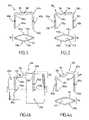
- FIG. 1illustrates a first exemplary osteosynthesis clip according to the present invention.
- FIG. 2illustrates a second exemplary osteosynthesis clip according to the present invention having gripping surfaces to frictionally engage the bone tissue.
- FIGS. 3 a through 3 dshow an operational sequence for inserting an osteosynthesis clip to couple bone tissue fragments.
- FIGS. 4 a and 4 billustrate a third exemplary osteosynthesis clip according to the present invention having a stepped-up section to set bone fragments having varying diameters.
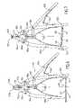
- FIGS. 5 a through 5 iillustrate a first exemplary fixation tool according to the present invention.
- FIG. 6illustrates a second exemplary fixation tool according to the present invention.
- FIG. 7illustrates a third exemplary fixation tool according to the present invention.
- FIG. 8 a through 8 cillustrate an operational sequence for removing a variant of the exemplary osteosynthesis clip of FIG. 1 after bone tissue has fused.
- FIG. 9illustrates a variant of the osteosynthesis clip shown in FIGS. 8 through 8 c.
- FIG. 10illustrates a variant of the osteosynthesis clip of FIG. 1 having a dome-shaped non-linear deformable region.
- Osteosynthesis clip 100includes at least two engagement legs 105 a , 105 b and a connecting bridge 110 to couple engagement legs 105 a , 105 b to one another, thereby forming a unitary clip 100 .
- Engagement legs 105 a , 105 bextend approximately parallel to one another and include respective proximal insertion tips 135 a , 135 b for insertion into the bone tissue and respective distal bridging tips 140 a , 140 b for coupling to bridge 110 .
- Engagement legs 105 a , 105 bmay have any cross section (e.g., round, square) suitable for insertion into bone, and may be provided with gripping surfaces 250 (e.g., gripping teeth) to frictionally engage the bone tissue (not shown), as shown in FIGS. 2 , 4 a , and 4 b.
- gripping surfaces 250e.g., gripping teeth
- the clip 100may be made of any material suitable for insertion into living tissue (e.g., bone tissue).
- clip 100may be made of a biocompatible material (e.g., stainless steel alloy or a titanium alloy metal such as TA6V of medical grade) having suitable elasticity and mechanical strength.
- Bridge 110includes two elongated sections 115 a , 115 b extending along side one another.
- the sections 115 a , 115 binclude respective bulges 120 a , 120 b , which together form a space 125 of separation between elongated sections 115 a , 115 b .
- elongated sections 115 a , 115 bextend side by side one another along a non-linear trajectory, thereby forming a non-linear deformable region 130 , such as a depression 130 .
- Deformable region 130is provided to facilitate clamping of bone tissue fragments (not shown), as more fully described below.
- Elongated sections 115 a , 115 b of bridge 110may also be provided with a stepped-up section 405 , as shown in FIG. 4 a .
- clip 100may be used to set bone fragments 410 a , 410 b having varying diameters, so that the axes of bone fragments 410 a , 410 b align with one another, as shown in FIG. 4 b.
- non-linear deformable region 130is provided in the form of dome 130 , instead of a depression.
- clip 100includes gripping surfaces 250 in the form of helical screw surfaces 805 a , 805 b provided near proximal insertion tips 135 a , 135 b to frictionally engage the bone tissue (not shown).
- engagement legs 105 a , 105 b of clip 100may be provided with any desired cross-section, such as a round cross-section, a square cross-section, an elliptical cross-section, etc.
- engagement legs 105 a , 105 bare provided with helical screw surfaces 805 a , 805 b , which advantageously facilitate the removal of clip 800 after the bone tissue (not shown) has been fused.
- clip 800may be cut in the locations of distal bridging tips 140 a , 140 b to remove bridge 110 , as shown in FIG. 8 b .
- engagement legs 105 a , 105 bmay be removed from the bone tissue, for example, by unscrewing engagement legs 105 a , 105 b in a counterclockwise direction 860 a , 860 b , as shown in FIG. 8 c .
- FIG. 8 cFIG.
- helical screw surfaces 805 a , 805 bare provided on an area of engagement legs 105 a , 105 b disposed toward distal bridging tips 140 a , 140 b . It should also be appreciated that helical screw surfaces 805 a , 805 b may be provided near proximal insertion tips 135 a , 135 b and near distal bridging tips 140 a , 140 b of engagement legs 105 a , 105 b.
- FIG. 3 a through 3 dthere is seen an operational sequence for inserting osteosynthesis clip 100 with a depression 130 to couple bone tissue fragments 305 a , 305 b .
- bone fragments 305 a , 305 bare pre-drilled with respective clip reception holes 310 a , 310 b for respectively receiving engagement legs 105 a , 105 b of osteosynthesis clip 100 .
- osteosynthesis clip 100is inserted into bone tissue fragments 305 a , 305 b , as shown in FIG. 3 b .
- clip 100may be coupled to an instrument (not shown), and a percussion force may be applied to the instrument (not shown) to drive clip 100 into bone tissue fragments 305 a , 305 b .
- a percussion forcemay be applied to the instrument (not shown) to drive clip 100 into bone tissue fragments 305 a , 305 b .
- the elongated sections 115 a , 115 bare separated, for example, by the instrument and/or a separate tool (not shown), as shown in FIG. 3 c .
- Thiscauses space 125 of clip 100 to widen along line A, thereby causing engagement legs 105 a , 105 b to approach one another to cause bone tissue fragments 305 a , 305 b to come in contact with one another under pressure.
- bone tissue fragments 305 a , 305 bcome in contact with one another under too high a pressure, elongated sections 115 a , 115 b may be brought closer together. This causes space 125 of clip 100 to narrow along line A, thereby causing engagement legs 105 a , 105 b to separate from one another.
- elongated sections 115 a , 115 bare over-separated (i.e., separated too much), for example, by a surgeon applying too much separation force on elongated sections 115 a , 115 b , the contact pressure between bone tissue fragments 305 a , 305 b in an area near the top surfaces 315 a , 315 b of bone tissue fragments 305 a , 305 b may exceed the contact pressure between bone tissue fragments 305 a , 305 b in an area near the bottom surfaces 320 a , 320 b of bone tissue fragments 305 a , 305 b .
- bone tissue fragments 305 a , 305 bmay pivot upwardly about contact pivot surface 325 , thereby causing engagement legs 105 a , 105 b of clip 100 to pivot away from one another about distal bridging tips 140 a , 140 b .
- the longitudinal axes of the bone tissue fragments 305 a , 305 bbecome unaligned and a gap 330 forms between the fragments 305 a , 305 b .
- merely bringing elongated sections 115 a , 115 b closer together to separate bone tissue fragments 305 a , 305 bmay not help alleviate the problem.
- a forcesuch as an upward force
- a forceis applied to elongated sections 115 a , 115 b of clip 100 in an area of non-linear deformable region 130 , as shown in FIG. 3 d .
- withdrawal of clip 100may be prevented by simultaneously applying an opposing force, such as a downward force, on distal bridging tips 140 a , 140 b .
- the force applied to elongated sections 115 a , 115 b of clip 100causes at least a partial linearization of non-linear deformable region 130 .
- proximal insertion tips 135 a , 135 bpivot toward one another about distal bridging tips 140 a , 140 b , thereby causing gap 330 to close between the bottom surfaces 320 a , 320 b of bone tissue fragments 305 a , 305 b , as shown in FIG. 3 d.
- the operational sequence of FIGS. 3 a through 3 dmay be performed to couple bone tissue fragments 305 a , 305 b with only minor modification. Specifically, after inserting clip 100 into bone tissue fragments 305 a , 305 b , a downward force is applied to elongated sections 115 a , 115 b in an area of non-linear deformable dome 130 , before elongated sections 115 a , 115 b are separated. The downward force applied to elongated sections 115 a , 115 b of clip 100 causes elongated sections 115 a , 115 b to move away from one another.
- elongated sections 115 a , 115 b of clip 100may be separated to cause engagement legs 105 a , 105 b to approach one another, thereby causing bone tissue fragments 305 a , 305 b to come in contact with one another under pressure.
- This operational sequencemay be required when operating on bone having a pronounced tendency to axial flexion angulation (e.g., metacarpals).
- Clip 100 of FIG. 10may be applied, for example, to the dorsum of the hand.
- the axes of the bone tissue fragments 305 a , 305 bmay be corrected by flattening non-linear deformable dome 130 of bridge 110 , and bone tissue fragments 305 a , 305 b may be brought together by separating elongated sections 115 a , 115 b , as described above.
- Fixation tool 500configured to insert clip 100 into bone tissue fragments 305 a , 305 b .
- Fixation tool 500includes handles 505 a , 505 b , a set of engagement arms 515 a , 515 b respectively coupled to handles 505 a , 505 b , pivot arms 510 a , 510 b respectively and pivotally coupled to handles 505 a , 505 b , a first biasing arrangement 520 (e.g., a pair of biased spring clips, a spring, etc.) configured to bias handles 505 a , 505 b in a normally opened position, a spacing bolt 525 , a guiding bolt 530 coupled to pivot arms 510 a , 510 b , a pair of pushing plates 535 a , 535 b slidably coupled to guiding bolt 530 , a handle 505 c pivotally coupled to pushing plates 5
- a first biasing arrangement 520e.g., a pair of biased
- Fixation tool 500may be used to perform the operational sequence shown in FIG. 3 a through 3 d for inserting osteosynthesis clip 200 to couple bone tissue fragments 305 a , 305 b .
- osteosynthesis clip 100is inserted into bone tissue fragments 305 a , 305 b , for example, using fixation tool 500 .
- engagement arms 515 a , 515 b of fixation tool 500are provided with respective engagement flanges 545 a , 545 b for fixedly engaging elongated sections 115 a , 115 b of clip 100 .
- osteosynthesis clip 100is inserted into bone tissue fragments 305 a , 305 b , as shown in FIG. 3 b .
- a percussion forcefor example, may be applied to handles 505 a and/or 505 b to drive clip 100 into bone tissue fragments 305 a , 305 b .
- clip 100may be inserted into bone tissue fragments 305 a , 305 b using a separate tool and/or percussion instrument, such as a surgical hammer.
- the elongated sections 115 a , 115 b of clip 100are separated to cause bone tissue fragments 305 a , 305 b to contact one another under pressure.
- a userfor example, a surgeon, applies a first squeezing force to handles 505 a , 505 b against the biasing force of first biasing arrangement 520 , as shown in FIGS. 5 d through 5 f .
- handles 505 a , 505 bto respectively pivot about pivot arms 510 a , 510 b , thereby causing engagement flanges 545 a , 545 b of engagement arms 515 a , 515 b to separate from one another, as shown in FIGS. 5 d through 5 f .
- Thiscauses space 125 of clip 100 to widen, thereby causing engagement legs 105 a , 105 b of clip 100 to approach one another to cause bone tissue fragments 305 a , 305 b to come in contact with one another under pressure.
- the userWithout releasing the first squeezing force on handles 505 a , 505 b , the user (e.g., the surgeon) applies a second squeezing force to handles 505 b , 505 c against the biasing force of second biasing arrangement 540 , as shown in FIGS. 5 g through 5 i .
- Thiscauses handle 505 c to pivot about pivot pin 550 , thereby causing pushing plates 535 a , 535 b to respectively engage distal bridging tips 140 a , 140 b of clip 100 by sliding distally toward engagement flanges 545 a , 545 b.
- the forcee.g., an upward force
- the force applied to elongated sections 115 a , 115 b of clip 100causes at least a partial linearization of non-linear deformable region 130 (e.g., non-linear depression 130 ).
- Thiscauses proximal insertion tips 135 a , 135 b to pivot toward one another about distal bridging tips 140 a , 140 b , thereby causing gap 330 to close between the bottom surfaces 320 a , 320 b of bone tissue fragments 305 a , 305 b , as shown in FIG. 3 d.
- handle 505 bmay be provided with a ratchet arrangement 605 configured to prevent handles 505 a , 505 b from separating from one another after the first squeezing force is applied, as shown in FIG. 6 .
- Ratchet arrangement 605includes a connecting end 615 coupled to handle 505 b , a ratchet clip 610 provided with ratchet teeth 620 , and a third biasing arrangement 625 configured to bias at least a portion of ratchet clip 610 toward engagement arms 515 a , 515 b (e.g., a third biasing arrangement 625 configured to bias end 606 of ratchet clip 610 toward the bottom end of handle 505 a ).
- ratchet teeth 620 of ratchet clip 610engage with the bottom of handle 505 a , thereby preventing handles 505 a , 505 b from separating from one another as the second force is applied to handles 505 b , 505 c.
- handle 505 ais released from teeth 620 of ratchet clip 510 .
- the usere.g., the surgeon
- teeth 620 of ratchet clip 610disengage the bottom end of handle 505 a , thereby permitting handles 505 a , 505 b to separate from one anther via the biasing force produced by first biasing arrangement 520 .
- the connecting end of the ratchet arrangementmay be alternatively coupled to handle 505 a instead of handle 505 b .
- the third biasing arrangement 625biases end 606 of ratchet clip 610 toward the bottom end of handle 505 b.
- fixation tool 500is provided with a bolt retention arrangement 700 in lieu of ratchet arrangement 605 for preventing handles 505 a , 505 b from separating from one another after the first squeezing force is applied, as shown in FIG. 7 .
- Bolt retention arrangement 700includes a bolt receptacle 710 pivotally coupled to handle 505 b and a bolt 715 rotationally coupled to handle 505 a .
- Bolt 715includes a knob portion 720 and a threaded sleeve 725 configured to engage with a threaded inner surface (not shown) of bolt receptacle 710 .
- the bolt receptacle 710may be pivotally coupled to handle 505 a instead of handle 505 b and bolt 715 may be rotationally coupled to handle 505 a instead of handle 505 b.
- knob portion 720e.g., in a clockwise direction
- threaded sleeve 725engages with the threaded inner surface (not shown) of bolt receptacle 710 .
- Thiscauses threaded sleeve 725 to displace within bolt receptacle 710 toward handle 505 b .
- bolt retention arrangement 700prevents handles 505 a , 505 b from separating from one another as the second force is applied to handles 505 b , 505 c .
- handle 505 amay be released from handle 505 b by simply turning knob portion 720 (e.g., in a counter-clockwise direction) to cause threaded sleeve 725 to displace within bolt receptacle 710 away from handle 505 b.
Landscapes
- Health & Medical Sciences (AREA)
- Life Sciences & Earth Sciences (AREA)
- Surgery (AREA)
- Orthopedic Medicine & Surgery (AREA)
- Medical Informatics (AREA)
- Engineering & Computer Science (AREA)
- Biomedical Technology (AREA)
- Heart & Thoracic Surgery (AREA)
- Nuclear Medicine, Radiotherapy & Molecular Imaging (AREA)
- Molecular Biology (AREA)
- Animal Behavior & Ethology (AREA)
- General Health & Medical Sciences (AREA)
- Public Health (AREA)
- Veterinary Medicine (AREA)
- Rheumatology (AREA)
- Neurology (AREA)
- Surgical Instruments (AREA)
Abstract
Description
Claims (7)
Priority Applications (9)
| Application Number | Priority Date | Filing Date | Title |
|---|---|---|---|
| US10/634,410US7635367B2 (en) | 2003-08-05 | 2003-08-05 | Osteosynthesis clip and insertion tool for use with bone tissue fragments |
| ES04018509TES2411883T3 (en) | 2003-08-05 | 2004-08-04 | Osteosynthesis clip and insertion tool to insert the osteosynthesis clip into bone tissue fragments |
| EP04018509AEP1504723B1 (en) | 2003-08-05 | 2004-08-04 | Osteosynthesis clip and insertion tool for inserting the osteosynthesis clip into bone tissue fragments |
| PT40185092TPT1504723E (en) | 2003-08-05 | 2004-08-04 | OSTEOSINTHESIS CLIP AND INSERTION TOOL TO INSERT OSTEOSINTHESIS CLIP IN BONE TISSUE FRAGEMNOS |
| EP10012095AEP2335605A1 (en) | 2003-08-05 | 2004-08-04 | Insertion tool for inserting an osteosynthesis clip into bone tisssue fragments |
| US11/197,174US8211109B2 (en) | 2003-08-05 | 2005-08-04 | Osteosynthesis clip and insertion tool for inserting an osteosynthesis clip into bone tissue fragments |
| US12/629,783US8864764B2 (en) | 2003-08-05 | 2009-12-02 | Osteosynthesis clip and insertion tool for use with bone tissue fragments |
| US12/629,789US8372075B2 (en) | 2003-08-05 | 2009-12-02 | Osteosynthesis clip and insertion tool for use with bone tissue fragments |
| US14/491,364US9468436B2 (en) | 2003-08-05 | 2014-09-19 | Osteosynthesis clip and insertion tool for use with bone tissue fragments |
Applications Claiming Priority (1)
| Application Number | Priority Date | Filing Date | Title |
|---|---|---|---|
| US10/634,410US7635367B2 (en) | 2003-08-05 | 2003-08-05 | Osteosynthesis clip and insertion tool for use with bone tissue fragments |
Related Child Applications (3)
| Application Number | Title | Priority Date | Filing Date |
|---|---|---|---|
| US11/197,174ContinuationUS8211109B2 (en) | 2003-08-05 | 2005-08-04 | Osteosynthesis clip and insertion tool for inserting an osteosynthesis clip into bone tissue fragments |
| US12/629,783DivisionUS8864764B2 (en) | 2003-08-05 | 2009-12-02 | Osteosynthesis clip and insertion tool for use with bone tissue fragments |
| US12/629,789DivisionUS8372075B2 (en) | 2003-08-05 | 2009-12-02 | Osteosynthesis clip and insertion tool for use with bone tissue fragments |
Publications (2)
| Publication Number | Publication Date |
|---|---|
| US20050049600A1 US20050049600A1 (en) | 2005-03-03 |
| US7635367B2true US7635367B2 (en) | 2009-12-22 |
Family
ID=33552907
Family Applications (5)
| Application Number | Title | Priority Date | Filing Date |
|---|---|---|---|
| US10/634,410Expired - LifetimeUS7635367B2 (en) | 2003-08-05 | 2003-08-05 | Osteosynthesis clip and insertion tool for use with bone tissue fragments |
| US11/197,174Active2028-03-24US8211109B2 (en) | 2003-08-05 | 2005-08-04 | Osteosynthesis clip and insertion tool for inserting an osteosynthesis clip into bone tissue fragments |
| US12/629,789Expired - LifetimeUS8372075B2 (en) | 2003-08-05 | 2009-12-02 | Osteosynthesis clip and insertion tool for use with bone tissue fragments |
| US12/629,783Active2027-04-01US8864764B2 (en) | 2003-08-05 | 2009-12-02 | Osteosynthesis clip and insertion tool for use with bone tissue fragments |
| US14/491,364Expired - LifetimeUS9468436B2 (en) | 2003-08-05 | 2014-09-19 | Osteosynthesis clip and insertion tool for use with bone tissue fragments |
Family Applications After (4)
| Application Number | Title | Priority Date | Filing Date |
|---|---|---|---|
| US11/197,174Active2028-03-24US8211109B2 (en) | 2003-08-05 | 2005-08-04 | Osteosynthesis clip and insertion tool for inserting an osteosynthesis clip into bone tissue fragments |
| US12/629,789Expired - LifetimeUS8372075B2 (en) | 2003-08-05 | 2009-12-02 | Osteosynthesis clip and insertion tool for use with bone tissue fragments |
| US12/629,783Active2027-04-01US8864764B2 (en) | 2003-08-05 | 2009-12-02 | Osteosynthesis clip and insertion tool for use with bone tissue fragments |
| US14/491,364Expired - LifetimeUS9468436B2 (en) | 2003-08-05 | 2014-09-19 | Osteosynthesis clip and insertion tool for use with bone tissue fragments |
Country Status (4)
| Country | Link |
|---|---|
| US (5) | US7635367B2 (en) |
| EP (2) | EP1504723B1 (en) |
| ES (1) | ES2411883T3 (en) |
| PT (1) | PT1504723E (en) |
Cited By (38)
| Publication number | Priority date | Publication date | Assignee | Title |
|---|---|---|---|---|
| US20050273108A1 (en)* | 2003-08-05 | 2005-12-08 | Groiso Jorge A | Osteosynthesis clip and insertion tool for inserting an osteosynthesis clip into bone tissue fragments |
| US20100221088A1 (en)* | 2009-01-01 | 2010-09-02 | Nitzan Chamiel | System and Method for a Flexible Pin |
| WO2013016633A1 (en) | 2011-07-27 | 2013-01-31 | William Casey Fox | Bone staple, instrument and method of use and manufacturing |
| WO2013055824A1 (en) | 2011-10-10 | 2013-04-18 | William Casey Fox | Shape changing bone implant for enhanced healing |
| WO2014120955A1 (en) | 2013-01-31 | 2014-08-07 | William Casey Fox | Bone staple extrusion instrument and method of use and manufacturing |
| AU2014200907B2 (en)* | 2013-03-15 | 2015-08-20 | Stryker Corporation | Bone staple storage, inserter, and method for use therewith |
| USD777329S1 (en) | 2015-10-19 | 2017-01-24 | Nextremity Solutions, Inc. | Bone staple |
| US9675395B2 (en) | 2011-11-07 | 2017-06-13 | Adsm | Osteosynthesis clip |
| US9901338B2 (en) | 2014-11-19 | 2018-02-27 | Biomet Manufacturing, Llc | Shape memory compression staple |
| US9907551B2 (en)* | 2014-08-04 | 2018-03-06 | Howmedica Osteonics Corp. | Surgical instrument for implanting fixation device |
| US9993246B1 (en) | 2017-07-07 | 2018-06-12 | Endure Enterprises, Pllc | Medical device bending devices and methods of use |
| US10010321B2 (en) | 2013-03-13 | 2018-07-03 | Stryker European Holdings I, Llc | Adjustable forceps for osteosynthesis clip |
| US10188388B2 (en) | 2016-02-16 | 2019-01-29 | Andronica Shontay Mandell Handie | Surgical staple insertion device |
| US10292770B2 (en) | 2017-04-21 | 2019-05-21 | Medicrea International | Systems, methods, and devices for developing patient-specific spinal treatments, operations, and procedures |
| US10314657B2 (en) | 2013-10-18 | 2019-06-11 | Medicrea International | Methods, systems, and devices for designing and manufacturing a spinal rod |
| US10318655B2 (en) | 2013-09-18 | 2019-06-11 | Medicrea International | Method making it possible to produce the ideal curvature of a rod of vertebral osteosynthesis material designed to support a patient's vertebral column |
| US10405894B2 (en) | 2014-02-14 | 2019-09-10 | Spectrum Spine Ip Holdings, Llc | Cervical minimal access fusion system |
| US10456211B2 (en) | 2015-11-04 | 2019-10-29 | Medicrea International | Methods and apparatus for spinal reconstructive surgery and measuring spinal length and intervertebral spacing, tension and rotation |
| US10918422B2 (en) | 2017-12-01 | 2021-02-16 | Medicrea International | Method and apparatus for inhibiting proximal junctional failure |
| US11311289B1 (en) | 2021-06-21 | 2022-04-26 | Pressio Inc. | Compression and fixation systems and processes for using the same |
| US11446024B2 (en) | 2012-07-30 | 2022-09-20 | Conextions, Inc. | Devices, systems, and methods for repairing soft tissue and attaching soft tissue to bone |
| US11547397B2 (en) | 2017-12-20 | 2023-01-10 | Conextions, Inc. | Devices, systems, and methods for repairing soft tissue and attaching soft tissue to bone |
| USD977640S1 (en) | 2021-06-21 | 2023-02-07 | Pressio, Inc. | Staple instrument |
| US11583384B2 (en) | 2014-03-12 | 2023-02-21 | Conextions, Inc. | Devices, systems, and methods for repairing soft tissue and attaching soft tissue to bone |
| US11612436B2 (en) | 2016-12-12 | 2023-03-28 | Medicrea International | Systems, methods, and devices for developing patient-specific medical treatments, operations, and procedures |
| US11696822B2 (en) | 2016-09-28 | 2023-07-11 | Conextions, Inc. | Devices, systems, and methods for repairing soft tissue and attaching soft tissue to bone |
| US11701218B2 (en)* | 2012-07-30 | 2023-07-18 | Conextions, Inc. | Soft tissue to bone repair devices, systems, and methods |
| USD996480S1 (en) | 2021-06-21 | 2023-08-22 | Pressio Inc. | Boring tool |
| USD998147S1 (en) | 2021-06-21 | 2023-09-05 | Pressio, Inc. | Boring tool handle |
| US11769251B2 (en) | 2019-12-26 | 2023-09-26 | Medicrea International | Systems and methods for medical image analysis |
| US11877801B2 (en) | 2019-04-02 | 2024-01-23 | Medicrea International | Systems, methods, and devices for developing patient-specific spinal implants, treatments, operations, and/or procedures |
| US11925417B2 (en) | 2019-04-02 | 2024-03-12 | Medicrea International | Systems, methods, and devices for developing patient-specific spinal implants, treatments, operations, and/or procedures |
| US11944531B2 (en) | 2012-07-30 | 2024-04-02 | Conextions, Inc. | Devices, systems, and methods for repairing soft tissue and attaching soft tissue to bone |
| US11957334B2 (en) | 2012-07-30 | 2024-04-16 | Conextions, Inc. | Devices, systems, and methods for repairing soft tissue and attaching soft tissue to bone |
| US11980360B2 (en) | 2012-07-30 | 2024-05-14 | Conextions, Inc. | Devices, systems, and methods for repairing soft tissue and attaching soft tissue to bone |
| US12102317B2 (en) | 2017-12-20 | 2024-10-01 | Conextions, Inc. | Devices, systems, and methods for repairing soft tissue and attaching soft tissue to bone |
| US12274511B2 (en) | 2019-04-02 | 2025-04-15 | Medicrea International | Systems and methods for medical image analysis |
| US12318144B2 (en) | 2021-06-23 | 2025-06-03 | Medicrea International SA | Systems and methods for planning a patient-specific spinal correction |
Families Citing this family (60)
| Publication number | Priority date | Publication date | Assignee | Title |
|---|---|---|---|---|
| US7052497B2 (en)* | 2002-08-14 | 2006-05-30 | Sdgi Holdings, Inc. | Techniques for spinal surgery and attaching constructs to vertebral elements |
| US7297146B2 (en)* | 2004-01-30 | 2007-11-20 | Warsaw Orthopedic, Inc. | Orthopedic distraction implants and techniques |
| FR2885514B1 (en)* | 2005-05-12 | 2007-07-06 | Medicrea Internat Sa | VERTEBRAL OSTEOSYNTHESIS EQUIPMENT |
| CN1907238B (en)* | 2005-08-04 | 2012-02-22 | J·A·格鲁瓦索 | Integrated bone clamp and surgical system comprising same |
| US20070049941A1 (en)* | 2005-08-25 | 2007-03-01 | Lanx, Llc | Plate with stabilization |
| FR2905588B1 (en)* | 2006-09-12 | 2008-11-14 | Small Bone Innovations Interna | SURGICAL CLIP. |
| CA2664591C (en)* | 2006-09-26 | 2014-12-02 | Synthes Usa, Llc | Transconnector |
| WO2008118295A2 (en)* | 2007-03-26 | 2008-10-02 | Laszlo Garamszegi | Bottom-loading pedicle screw assembly |
| JP2008307383A (en)* | 2007-06-12 | 2008-12-25 | Tyco Healthcare Group Lp | Surgical fastener |
| US20100080520A1 (en)* | 2008-05-12 | 2010-04-01 | Howard Lind | Flexible silicone cable system integrated with hollow tubing for fluid delivery |
| US8062297B2 (en)* | 2008-07-24 | 2011-11-22 | Biopro, Inc. | Bone fixation apparatus and method of manufacture |
| US12285197B2 (en) | 2008-10-10 | 2025-04-29 | Acumed Llc | Bone fixation system with opposed mounting portions |
| US9066757B2 (en) | 2009-08-10 | 2015-06-30 | Virak Orthopedic Research Llc | Orthopedic external fixator and method of use |
| US20110112558A1 (en)* | 2009-10-02 | 2011-05-12 | OC2, LLC, a Massachusetts limited liability company | Tissue fixation system with single component anchor |
| US9480511B2 (en) | 2009-12-17 | 2016-11-01 | Engage Medical Holdings, Llc | Blade fixation for ankle fusion and arthroplasty |
| EP2651341B1 (en) | 2010-12-16 | 2017-01-04 | Engage Medical Holdings, LLC | Arthroplasty systems and methods |
| WO2012135530A1 (en) | 2011-03-29 | 2012-10-04 | Ocunetics, Inc. | Fasteners, deployment systems, and methods for ophthalmic tissue closure and fixation of ophthalmic prostheses and other uses |
| ES2633746T3 (en)* | 2011-07-18 | 2017-09-25 | Woodwelding Ag | Implant to stabilize each other separate bone portions |
| WO2013049849A2 (en) | 2011-09-30 | 2013-04-04 | Acute Innovations, Llc, An Oregon Limited Liability Company | Bone fixation system with opposed mounting portions |
| US9615856B2 (en) | 2011-11-01 | 2017-04-11 | Imds Llc | Sacroiliac fusion cage |
| US9254130B2 (en) | 2011-11-01 | 2016-02-09 | Hyun Bae | Blade anchor systems for bone fusion |
| EP2787898B1 (en) | 2011-12-08 | 2019-05-01 | O3 Optix LLC | Fasteners, deployment systems, and methods for ophthalmic tissue closure and fixation of ophthalmic prosthesis and other uses |
| US8584853B2 (en) | 2012-02-16 | 2013-11-19 | Biomedical Enterprises, Inc. | Method and apparatus for an orthopedic fixation system |
| US10238382B2 (en) | 2012-03-26 | 2019-03-26 | Engage Medical Holdings, Llc | Blade anchor for foot and ankle |
| WO2014085870A1 (en) | 2012-12-08 | 2014-06-12 | Kevin Seex | Surgical tool |
| US20140276830A1 (en)* | 2013-03-14 | 2014-09-18 | Daniel F. Cheney | Bone staples and methods of use therefor and manufacturing thereof |
| ES2647540T3 (en)* | 2013-04-04 | 2017-12-22 | Aristotech Industries Gmbh | Staple implant to influence growth in bone areas adjacent to a growth cartilage |
| US9585656B2 (en) | 2013-06-03 | 2017-03-07 | Biomedical Enterprises, Inc. | Method and apparatus for loading and implanting a shape memory implant |
| CN106102612B (en) | 2013-11-11 | 2020-07-21 | 阿特雷克斯公司 | Screw for generating and applying compression in the body |
| EP3068325B1 (en) | 2013-11-13 | 2021-09-15 | Arthrex, Inc. | Intermedullary devices for generating and applying compression within a body |
| AU2014365821B2 (en) | 2013-12-20 | 2019-10-03 | Crossroads Extremity Systems, Llc | Polyaxial locking hole |
| US20150173749A1 (en)* | 2013-12-23 | 2015-06-25 | Ethicon Endo-Surgery, Inc. | Surgical staples and staple cartridges |
| RU2690106C2 (en)* | 2013-12-23 | 2019-05-30 | ЭТИКОН ЭНДО-СЕРДЖЕРИ, ЭлЭлСи | SURGICAL BRACKETS AND METHODS OF THEIR MANUFACTURE |
| US9408647B2 (en) | 2014-02-27 | 2016-08-09 | Biomedical Enterprises, Inc. | Method and apparatus for use of a compressing plate |
| US10499908B2 (en) | 2014-03-04 | 2019-12-10 | Maquet Cardiovascular Llc | Surgical implant and method and instrument for installing the same |
| WO2015134682A1 (en) | 2014-03-04 | 2015-09-11 | Maquet Cardiovascular Llc | Surgical implant and method and instrument for installing the same |
| US10456130B2 (en)* | 2014-05-07 | 2019-10-29 | Biomedical Enterprises, Inc. | Method and apparatus for loading and implanting a shape memory implant |
| US10456131B2 (en) | 2014-05-07 | 2019-10-29 | Biomedical Enterprises, Inc. | Method and apparatus for loading and implanting a shape memory implant |
| EP3166505B1 (en)* | 2014-07-10 | 2019-10-09 | Crossroads Extremity Systems, LLC | Bone implant with anti-rotation |
| JP2017529886A (en) | 2014-07-10 | 2017-10-12 | クロスローズ エクストリミティ システムズ リミテッド ライアビリティ カンパニー | Bone implant and means of insertion |
| US11202626B2 (en) | 2014-07-10 | 2021-12-21 | Crossroads Extremity Systems, Llc | Bone implant with means for multi directional force and means of insertion |
| US9883897B2 (en) | 2014-09-25 | 2018-02-06 | Biomedical Enterprises, Inc. | Method and apparatus for a compressing plate |
| WO2016123382A1 (en) | 2015-01-28 | 2016-08-04 | Mx Orthopedics, Corp. | Self-compressing screws for generating and applying compression within a body |
| WO2016154417A1 (en)* | 2015-03-24 | 2016-09-29 | Mẍ Orthopedics, Corp. | Staples for generating and applying compression within a body |
| WO2017040732A2 (en) | 2015-09-03 | 2017-03-09 | Biomedical Enterprises, Inc. | Elastic orthopedic implant and method of manufacture thereof |
| US10390955B2 (en) | 2016-09-22 | 2019-08-27 | Engage Medical Holdings, Llc | Bone implants |
| CN106344094B (en)* | 2016-09-30 | 2018-10-23 | 吉林大学第一医院 | Digestive tract lesion wound surface sealing telescopic clamp |
| US10568627B2 (en)* | 2016-12-07 | 2020-02-25 | Ethicon, Inc. | Surgical fasteners for mesh and tissue fixation |
| US10918381B2 (en) | 2016-12-07 | 2021-02-16 | Ethicon, Inc. | Applicator instruments having drive systems with flexible members for dispensing surgical fasteners |
| US11864753B2 (en) | 2017-02-06 | 2024-01-09 | Crossroads Extremity Systems, Llc | Implant inserter |
| EP3579762B1 (en) | 2017-02-07 | 2024-06-26 | Crossroads Extremity Systems, LLC | Counter-torque implant |
| US11540928B2 (en) | 2017-03-03 | 2023-01-03 | Engage Uni Llc | Unicompartmental knee arthroplasty |
| US10456272B2 (en) | 2017-03-03 | 2019-10-29 | Engage Uni Llc | Unicompartmental knee arthroplasty |
| US10842487B2 (en) | 2017-10-20 | 2020-11-24 | Biomedical Enterprises, Inc. | Method and apparatus for loading and implanting a shape memory implant |
| US20200046345A1 (en)* | 2018-08-13 | 2020-02-13 | Thomas Zink | Variable Compression Bone Staple System |
| US11523820B2 (en) | 2020-01-29 | 2022-12-13 | DePuy Synthes Products, Inc. | Shape memory implants and a method and apparatus for the loading and implanting thereof |
| US12042386B2 (en) | 2020-01-29 | 2024-07-23 | DePuy Synthes Products, Inc. | Shape memory implants and methods and apparatus for the loading and implanting thereof |
| US12059183B2 (en) | 2020-07-31 | 2024-08-13 | Crossroads Extremity Systems, Llc | Bone plates with dynamic elements and screws |
| US11801050B2 (en) | 2020-10-06 | 2023-10-31 | Covidien Lp | Hand-held surgical instruments |
| USD961081S1 (en) | 2020-11-18 | 2022-08-16 | Crossroads Extremity Systems, Llc | Orthopedic implant |
Citations (10)
| Publication number | Priority date | Publication date | Assignee | Title |
|---|---|---|---|---|
| US211404A (en)* | 1879-01-14 | Improvement in electro-magnetic motors | ||
| US4456006A (en)* | 1980-11-10 | 1984-06-26 | Queen's University At Kingston | Contracting bone clip |
| US4887601A (en)* | 1987-11-06 | 1989-12-19 | Ophthalmic Ventures Limited Partnership | Adjustable surgical staple and method of using the same |
| US5366479A (en)* | 1991-10-18 | 1994-11-22 | United States Surgical Corporation | Surgical staple for attaching an object to body tissue |
| US5449359A (en) | 1991-09-05 | 1995-09-12 | Groiso; Jorge A. | Elastic clip for osteosynthesis |
| US5827283A (en) | 1996-03-21 | 1998-10-27 | Groiso; Jorge Abel | Device and method for locating two bones into a desired relative position |
| US5947999A (en) | 1996-12-03 | 1999-09-07 | Groiso; Jorge A. | Surgical clip and method |
| US6767356B2 (en)* | 2000-09-01 | 2004-07-27 | Angiolink Corporation | Advanced wound site management systems and methods |
| US6773437B2 (en)* | 1999-04-23 | 2004-08-10 | Sdgi Holdings, Inc. | Shape memory alloy staple |
| US20050273108A1 (en)* | 2003-08-05 | 2005-12-08 | Groiso Jorge A | Osteosynthesis clip and insertion tool for inserting an osteosynthesis clip into bone tissue fragments |
Family Cites Families (12)
| Publication number | Priority date | Publication date | Assignee | Title |
|---|---|---|---|---|
| US4256251A (en)* | 1978-04-24 | 1981-03-17 | Lawrence M. Smith | Surgical staplers and staple |
| US4263903A (en)* | 1979-01-08 | 1981-04-28 | Richards Manufacturing Co., Inc. | Medical staple means |
| FR2562416B1 (en)* | 1984-04-06 | 1988-07-01 | Orthomed | OSTEOSYNTHESIS CLIP |
| CA1286185C (en)* | 1986-07-14 | 1991-07-16 | Harold E. Froehlich | Bent back box staple and staple closing mechanism with split actuator |
| FR2668361A1 (en)* | 1990-10-30 | 1992-04-30 | Mai Christian | OSTEOSYNTHESIS CLIP AND PLATE WITH SELF-RETENTIVE DYNAMIC COMPRESSION. |
| FR2693899B1 (en)* | 1992-07-24 | 1994-09-23 | Laboureau Jacques | Osteosynthesis plate clip. |
| KR0155605B1 (en)* | 1995-10-11 | 1998-11-16 | 배대경 | Mini plate staple |
| EP0955011A1 (en)* | 1998-05-06 | 1999-11-10 | EOS Sarl | Orthopaedic staple |
| US6554852B1 (en)* | 1999-08-25 | 2003-04-29 | Michael A. Oberlander | Multi-anchor suture |
| US7618441B2 (en)* | 2002-01-22 | 2009-11-17 | Jorge Abel Groiso | Bone staple and methods for correcting spine disorders |
| US6966911B2 (en)* | 2002-01-22 | 2005-11-22 | Jorge Abel Groiso | Bone staple and methods for correcting bone deficiencies by controllably suppressing and/or inducing the growth of the epiphyseal plate |
| DE20204513U1 (en)* | 2002-03-14 | 2002-08-08 | Merete Medical GmbH, 12247 Berlin | Step plate for the osteotomy |
- 2003
- 2003-08-05USUS10/634,410patent/US7635367B2/ennot_activeExpired - Lifetime
- 2004
- 2004-08-04EPEP04018509Apatent/EP1504723B1/ennot_activeExpired - Lifetime
- 2004-08-04EPEP10012095Apatent/EP2335605A1/ennot_activeWithdrawn
- 2004-08-04PTPT40185092Tpatent/PT1504723E/enunknown
- 2004-08-04ESES04018509Tpatent/ES2411883T3/ennot_activeExpired - Lifetime
- 2005
- 2005-08-04USUS11/197,174patent/US8211109B2/enactiveActive
- 2009
- 2009-12-02USUS12/629,789patent/US8372075B2/ennot_activeExpired - Lifetime
- 2009-12-02USUS12/629,783patent/US8864764B2/enactiveActive
- 2014
- 2014-09-19USUS14/491,364patent/US9468436B2/ennot_activeExpired - Lifetime
Patent Citations (13)
| Publication number | Priority date | Publication date | Assignee | Title |
|---|---|---|---|---|
| US211404A (en)* | 1879-01-14 | Improvement in electro-magnetic motors | ||
| US4456006A (en)* | 1980-11-10 | 1984-06-26 | Queen's University At Kingston | Contracting bone clip |
| US4887601A (en)* | 1987-11-06 | 1989-12-19 | Ophthalmic Ventures Limited Partnership | Adjustable surgical staple and method of using the same |
| US5853414A (en) | 1991-05-09 | 1998-12-29 | Groiso; Jorge A. | Elastic clip for osteosynthesis |
| US5660188A (en) | 1991-05-09 | 1997-08-26 | Groiso; Jorge A. | Procedure for applying an elastic clip |
| US5449359A (en) | 1991-09-05 | 1995-09-12 | Groiso; Jorge A. | Elastic clip for osteosynthesis |
| US5366479A (en)* | 1991-10-18 | 1994-11-22 | United States Surgical Corporation | Surgical staple for attaching an object to body tissue |
| US5827283A (en) | 1996-03-21 | 1998-10-27 | Groiso; Jorge Abel | Device and method for locating two bones into a desired relative position |
| US5947999A (en) | 1996-12-03 | 1999-09-07 | Groiso; Jorge A. | Surgical clip and method |
| US5993476A (en) | 1996-12-03 | 1999-11-30 | Groiso; Jorge A. | Surgical clip and method |
| US6773437B2 (en)* | 1999-04-23 | 2004-08-10 | Sdgi Holdings, Inc. | Shape memory alloy staple |
| US6767356B2 (en)* | 2000-09-01 | 2004-07-27 | Angiolink Corporation | Advanced wound site management systems and methods |
| US20050273108A1 (en)* | 2003-08-05 | 2005-12-08 | Groiso Jorge A | Osteosynthesis clip and insertion tool for inserting an osteosynthesis clip into bone tissue fragments |
Cited By (70)
| Publication number | Priority date | Publication date | Assignee | Title |
|---|---|---|---|---|
| US8864764B2 (en)* | 2003-08-05 | 2014-10-21 | Medicrea International | Osteosynthesis clip and insertion tool for use with bone tissue fragments |
| US20100082030A1 (en)* | 2003-08-05 | 2010-04-01 | Medicrea International | Osteosynthesis clip and insertion tool for use with bone tissue fragments |
| US20100087822A1 (en)* | 2003-08-05 | 2010-04-08 | Medicrea International | Osteosynthesis clip and insertion tool for use with bone tissue fragments |
| US8211109B2 (en) | 2003-08-05 | 2012-07-03 | Medicrea International | Osteosynthesis clip and insertion tool for inserting an osteosynthesis clip into bone tissue fragments |
| US20050273108A1 (en)* | 2003-08-05 | 2005-12-08 | Groiso Jorge A | Osteosynthesis clip and insertion tool for inserting an osteosynthesis clip into bone tissue fragments |
| US8372075B2 (en)* | 2003-08-05 | 2013-02-12 | Medicrea International | Osteosynthesis clip and insertion tool for use with bone tissue fragments |
| US9468436B2 (en) | 2003-08-05 | 2016-10-18 | Medicrea International | Osteosynthesis clip and insertion tool for use with bone tissue fragments |
| US20100221088A1 (en)* | 2009-01-01 | 2010-09-02 | Nitzan Chamiel | System and Method for a Flexible Pin |
| US9339268B2 (en) | 2011-07-27 | 2016-05-17 | William Casey Fox | Bone staple, instrument and method of use and manufacturing |
| US9017331B2 (en) | 2011-07-27 | 2015-04-28 | William Casey Fox | Bone staple, instrument and method of use and manufacturing |
| US10512459B2 (en) | 2011-07-27 | 2019-12-24 | William Casey Fox | Bone staple, instrument and method of use and manufacturing |
| US9743926B2 (en) | 2011-07-27 | 2017-08-29 | William Casey Fox | Bone staple, instrument and method of use and manufacturing |
| US9451957B2 (en) | 2011-07-27 | 2016-09-27 | William Casey Fox | Bone staple extrusion instrument and method of use and manufacturing |
| WO2013016633A1 (en) | 2011-07-27 | 2013-01-31 | William Casey Fox | Bone staple, instrument and method of use and manufacturing |
| USRE49667E1 (en) | 2011-10-10 | 2023-09-26 | William Casey Fox | Shape changing bone implant and method of use for enhancing healing |
| WO2013055824A1 (en) | 2011-10-10 | 2013-04-18 | William Casey Fox | Shape changing bone implant for enhanced healing |
| US10448979B2 (en) | 2011-10-10 | 2019-10-22 | William Casey Fox | Shape changing bone implant and method of use for enhancing healing |
| US9675395B2 (en) | 2011-11-07 | 2017-06-13 | Adsm | Osteosynthesis clip |
| US11980360B2 (en) | 2012-07-30 | 2024-05-14 | Conextions, Inc. | Devices, systems, and methods for repairing soft tissue and attaching soft tissue to bone |
| US11957334B2 (en) | 2012-07-30 | 2024-04-16 | Conextions, Inc. | Devices, systems, and methods for repairing soft tissue and attaching soft tissue to bone |
| US11944531B2 (en) | 2012-07-30 | 2024-04-02 | Conextions, Inc. | Devices, systems, and methods for repairing soft tissue and attaching soft tissue to bone |
| US11701218B2 (en)* | 2012-07-30 | 2023-07-18 | Conextions, Inc. | Soft tissue to bone repair devices, systems, and methods |
| US11446024B2 (en) | 2012-07-30 | 2022-09-20 | Conextions, Inc. | Devices, systems, and methods for repairing soft tissue and attaching soft tissue to bone |
| WO2014120955A1 (en) | 2013-01-31 | 2014-08-07 | William Casey Fox | Bone staple extrusion instrument and method of use and manufacturing |
| US10010321B2 (en) | 2013-03-13 | 2018-07-03 | Stryker European Holdings I, Llc | Adjustable forceps for osteosynthesis clip |
| AU2014200907B2 (en)* | 2013-03-15 | 2015-08-20 | Stryker Corporation | Bone staple storage, inserter, and method for use therewith |
| US12417323B2 (en) | 2013-09-18 | 2025-09-16 | Medicrea International | Method of making it possible to produce and ideal curvature of a rod of vertebral osteosynthesis material designed to support a patient's vertebral column |
| US12019955B2 (en) | 2013-09-18 | 2024-06-25 | Medicrea International | Method making it possible to produce the ideal curvature of a rod of vertebral osteosynthesis material designed to support a patient's vertebral column |
| US10318655B2 (en) | 2013-09-18 | 2019-06-11 | Medicrea International | Method making it possible to produce the ideal curvature of a rod of vertebral osteosynthesis material designed to support a patient's vertebral column |
| US10970426B2 (en) | 2013-09-18 | 2021-04-06 | Medicrea International SA | Methods, systems, and devices for designing and manufacturing a spinal rod |
| US10433912B1 (en) | 2013-10-18 | 2019-10-08 | Medicrea International | Methods, systems, and devices for designing and manufacturing a spinal rod |
| US10413365B1 (en) | 2013-10-18 | 2019-09-17 | Medicrea International | Methods, systems, and devices for designing and manufacturing a spinal rod |
| US10441363B1 (en) | 2013-10-18 | 2019-10-15 | Medicrea International | Methods, systems, and devices for designing and manufacturing a spinal rod |
| US12257000B2 (en) | 2013-10-18 | 2025-03-25 | Medicrea International | Methods, systems, and devices for designing and manufacturing a spinal rod |
| US10314657B2 (en) | 2013-10-18 | 2019-06-11 | Medicrea International | Methods, systems, and devices for designing and manufacturing a spinal rod |
| US10433913B2 (en) | 2013-10-18 | 2019-10-08 | Medicrea International | Methods, systems, and devices for designing and manufacturing a spinal rod |
| US11918295B2 (en) | 2013-10-18 | 2024-03-05 | Medicrea International | Methods, systems, and devices for designing and manufacturing a spinal rod |
| US10426553B2 (en) | 2013-10-18 | 2019-10-01 | Medicrea International | Methods, systems, and devices for designing and manufacturing a spinal rod |
| US10973582B2 (en) | 2013-10-18 | 2021-04-13 | Medicrea International | Methods, systems, and devices for designing and manufacturing a spinal rod |
| US10420615B1 (en) | 2013-10-18 | 2019-09-24 | Medicrea International | Methods, systems, and devices for designing and manufacturing a spinal rod |
| US11197719B2 (en) | 2013-10-18 | 2021-12-14 | Medicrea International | Methods, systems, and devices for designing and manufacturing a spinal rod |
| US11197718B2 (en) | 2013-10-18 | 2021-12-14 | Medicrea Iniernational | Methods, systems, and devices for designing and manufacturing a spinal rod |
| US10405894B2 (en) | 2014-02-14 | 2019-09-10 | Spectrum Spine Ip Holdings, Llc | Cervical minimal access fusion system |
| US11583384B2 (en) | 2014-03-12 | 2023-02-21 | Conextions, Inc. | Devices, systems, and methods for repairing soft tissue and attaching soft tissue to bone |
| US9907551B2 (en)* | 2014-08-04 | 2018-03-06 | Howmedica Osteonics Corp. | Surgical instrument for implanting fixation device |
| US9901338B2 (en) | 2014-11-19 | 2018-02-27 | Biomet Manufacturing, Llc | Shape memory compression staple |
| USD777329S1 (en) | 2015-10-19 | 2017-01-24 | Nextremity Solutions, Inc. | Bone staple |
| US10456211B2 (en) | 2015-11-04 | 2019-10-29 | Medicrea International | Methods and apparatus for spinal reconstructive surgery and measuring spinal length and intervertebral spacing, tension and rotation |
| US10188388B2 (en) | 2016-02-16 | 2019-01-29 | Andronica Shontay Mandell Handie | Surgical staple insertion device |
| US11696822B2 (en) | 2016-09-28 | 2023-07-11 | Conextions, Inc. | Devices, systems, and methods for repairing soft tissue and attaching soft tissue to bone |
| US12178516B2 (en) | 2016-12-12 | 2024-12-31 | Medicrea International | Systems, methods, and devices for developing patient-specific medical treatments, operations, and procedures |
| US11612436B2 (en) | 2016-12-12 | 2023-03-28 | Medicrea International | Systems, methods, and devices for developing patient-specific medical treatments, operations, and procedures |
| US12004814B2 (en) | 2017-04-21 | 2024-06-11 | Medicrea International | Systems, methods, and devices for developing patient-specific spinal treatments, operations, and procedures |
| US11185369B2 (en) | 2017-04-21 | 2021-11-30 | Medicrea Nternational | Systems, methods, and devices for developing patient-specific spinal treatments, operations, and procedures |
| US10292770B2 (en) | 2017-04-21 | 2019-05-21 | Medicrea International | Systems, methods, and devices for developing patient-specific spinal treatments, operations, and procedures |
| US9993246B1 (en) | 2017-07-07 | 2018-06-12 | Endure Enterprises, Pllc | Medical device bending devices and methods of use |
| US10918422B2 (en) | 2017-12-01 | 2021-02-16 | Medicrea International | Method and apparatus for inhibiting proximal junctional failure |
| US12102317B2 (en) | 2017-12-20 | 2024-10-01 | Conextions, Inc. | Devices, systems, and methods for repairing soft tissue and attaching soft tissue to bone |
| US11547397B2 (en) | 2017-12-20 | 2023-01-10 | Conextions, Inc. | Devices, systems, and methods for repairing soft tissue and attaching soft tissue to bone |
| US11925417B2 (en) | 2019-04-02 | 2024-03-12 | Medicrea International | Systems, methods, and devices for developing patient-specific spinal implants, treatments, operations, and/or procedures |
| US11877801B2 (en) | 2019-04-02 | 2024-01-23 | Medicrea International | Systems, methods, and devices for developing patient-specific spinal implants, treatments, operations, and/or procedures |
| US12251165B2 (en) | 2019-04-02 | 2025-03-18 | Medicrea International | Systems, methods, and devices for developing patient-specific spinal implants, treatments, operations, and/or procedures |
| US12274511B2 (en) | 2019-04-02 | 2025-04-15 | Medicrea International | Systems and methods for medical image analysis |
| US11769251B2 (en) | 2019-12-26 | 2023-09-26 | Medicrea International | Systems and methods for medical image analysis |
| US11974739B1 (en) | 2021-06-21 | 2024-05-07 | Pressio Inc. | Compression and fixation systems and processes for using the same |
| USD998147S1 (en) | 2021-06-21 | 2023-09-05 | Pressio, Inc. | Boring tool handle |
| US11311289B1 (en) | 2021-06-21 | 2022-04-26 | Pressio Inc. | Compression and fixation systems and processes for using the same |
| USD996480S1 (en) | 2021-06-21 | 2023-08-22 | Pressio Inc. | Boring tool |
| USD977640S1 (en) | 2021-06-21 | 2023-02-07 | Pressio, Inc. | Staple instrument |
| US12318144B2 (en) | 2021-06-23 | 2025-06-03 | Medicrea International SA | Systems and methods for planning a patient-specific spinal correction |
Also Published As
| Publication number | Publication date |
|---|---|
| ES2411883T3 (en) | 2013-07-09 |
| US20100082030A1 (en) | 2010-04-01 |
| US8372075B2 (en) | 2013-02-12 |
| US20050273108A1 (en) | 2005-12-08 |
| US20150011999A1 (en) | 2015-01-08 |
| PT1504723E (en) | 2013-06-04 |
| EP2335605A1 (en) | 2011-06-22 |
| US8864764B2 (en) | 2014-10-21 |
| EP1504723A3 (en) | 2005-12-14 |
| US20100087822A1 (en) | 2010-04-08 |
| US20050049600A1 (en) | 2005-03-03 |
| US8211109B2 (en) | 2012-07-03 |
| EP1504723B1 (en) | 2013-03-06 |
| US9468436B2 (en) | 2016-10-18 |
| EP1504723A2 (en) | 2005-02-09 |
Similar Documents
| Publication | Publication Date | Title |
|---|---|---|
| US7635367B2 (en) | Osteosynthesis clip and insertion tool for use with bone tissue fragments | |
| US20250268594A1 (en) | Bone staple storage, inserter, and method for use therewith | |
| EP2563252B1 (en) | Bone fixation systems | |
| JP4320263B2 (en) | Rod pusher | |
| US6379363B1 (en) | Method and apparatus for reattachment of a cranial flap using a cranial clamp | |
| US8597337B2 (en) | Joint fusion device | |
| US8475457B2 (en) | Clip-like implant for osteosynthesis | |
| US5578032A (en) | Bone clamp | |
| EP1044653B1 (en) | Bone clamp for dynamic and non-dynamic compression of fractures | |
| US12329376B2 (en) | Bone clip with resilient arm for proximal compression | |
| CN111493994B (en) | Bone reduction clamp and plate holding clamp | |
| US10932833B2 (en) | Bone compression device and method | |
| US20090125070A1 (en) | Fracture Fixation Plate for the Coronoid of the Proximal Ulna | |
| US20110106183A1 (en) | Plate Holding Bone Forceps and Method of Use | |
| JP2007532243A (en) | Bar-shaped purse aider | |
| US8777953B1 (en) | Rocker mechanism | |
| HK1075595A (en) | Osteosynthesis clip and insertion tool for inserting an osteosynthesis clip into bone tissue fragments | |
| CN209236359U (en) | surgical tools | |
| CN115209834A (en) | Implant for fusing at least two bone members and method for fusing bone members using implant | |
| HK1032519B (en) | Bone clamp for dynamic and non-dynamic compression of fractures |
Legal Events
| Date | Code | Title | Description |
|---|---|---|---|
| AS | Assignment | Owner name:MEDICREA INTERNATIONAL, FRANCE Free format text:ASSIGNMENT OF ASSIGNORS INTEREST;ASSIGNOR:GROISO, JORGE ABEL;REEL/FRAME:021679/0716 Effective date:20080516 Owner name:NEWDEAL, FRANCE Free format text:PATENT LICENSE AGREEMENT;ASSIGNOR:MEDICREA INTERNATIONAL;REEL/FRAME:021679/0666 Effective date:20080513 | |
| STCF | Information on status: patent grant | Free format text:PATENTED CASE | |
| FEPP | Fee payment procedure | Free format text:PAT HOLDER CLAIMS SMALL ENTITY STATUS, ENTITY STATUS SET TO SMALL (ORIGINAL EVENT CODE: LTOS); ENTITY STATUS OF PATENT OWNER: LARGE ENTITY | |
| FPAY | Fee payment | Year of fee payment:4 | |
| FPAY | Fee payment | Year of fee payment:8 | |
| AS | Assignment | Owner name:PERCEPTIVE CREDIT HOLDINGS II, LP, NEW YORK Free format text:PATENT SECURITY AGREEMENT;ASSIGNOR:MEDICREA INTERNATIONAL;REEL/FRAME:048174/0183 Effective date:20181127 | |
| AS | Assignment | Owner name:MEDICREA INTERNATIONAL, FRANCE Free format text:RELEASE BY SECURED PARTY;ASSIGNOR:PERCEPTIVE CREDIT HOLDINGS II, LP;REEL/FRAME:054485/0305 Effective date:20201113 | |
| FEPP | Fee payment procedure | Free format text:ENTITY STATUS SET TO UNDISCOUNTED (ORIGINAL EVENT CODE: BIG.); ENTITY STATUS OF PATENT OWNER: LARGE ENTITY | |
| MAFP | Maintenance fee payment | Free format text:PAYMENT OF MAINTENANCE FEE, 12TH YEAR, LARGE ENTITY (ORIGINAL EVENT CODE: M1553); ENTITY STATUS OF PATENT OWNER: LARGE ENTITY Year of fee payment:12 |