US7635364B2 - Unidirectional translation system for bone fixation - Google Patents
Unidirectional translation system for bone fixationDownload PDFInfo
- Publication number
- US7635364B2 US7635364B2US11/001,902US190204AUS7635364B2US 7635364 B2US7635364 B2US 7635364B2US 190204 AUS190204 AUS 190204AUS 7635364 B2US7635364 B2US 7635364B2
- Authority
- US
- United States
- Prior art keywords
- plate
- teeth
- assembly
- fastener
- securing
- Prior art date
- Legal status (The legal status is an assumption and is not a legal conclusion. Google has not performed a legal analysis and makes no representation as to the accuracy of the status listed.)
- Expired - Fee Related, expires
Links
- 210000000988bone and boneAnatomy0.000titleclaimsdescription59
- 238000013519translationMethods0.000titledescription6
- 238000005553drillingMethods0.000claimsdescription2
- 238000010079rubber tappingMethods0.000claimsdescription2
- 230000000750progressive effectEffects0.000abstractdescription4
- 125000006850spacer groupChemical group0.000description26
- 230000004927fusionEffects0.000description14
- 230000009286beneficial effectEffects0.000description12
- 230000006835compressionEffects0.000description12
- 238000007906compressionMethods0.000description12
- 238000000034methodMethods0.000description12
- 238000011065in-situ storageMethods0.000description5
- 238000003780insertionMethods0.000description5
- 230000037431insertionEffects0.000description5
- 230000000712assemblyEffects0.000description4
- 238000000429assemblyMethods0.000description4
- 239000000463materialSubstances0.000description4
- 230000008901benefitEffects0.000description3
- 230000002980postoperative effectEffects0.000description3
- 230000001054cortical effectEffects0.000description2
- 230000003247decreasing effectEffects0.000description2
- 230000003278mimic effectEffects0.000description2
- 238000012986modificationMethods0.000description2
- 230000004048modificationEffects0.000description2
- 230000000007visual effectEffects0.000description2
- 229910001069Ti alloyInorganic materials0.000description1
- 238000007792additionMethods0.000description1
- 238000013461designMethods0.000description1
- 230000000694effectsEffects0.000description1
- 238000002513implantationMethods0.000description1
- 238000010348incorporationMethods0.000description1
- 230000000399orthopedic effectEffects0.000description1
- 230000002265preventionEffects0.000description1
- 230000001737promoting effectEffects0.000description1
- 238000000926separation methodMethods0.000description1
- 238000006467substitution reactionMethods0.000description1
- 238000001356surgical procedureMethods0.000description1
- 238000003786synthesis reactionMethods0.000description1
- -1titanium-aluminum-niobiumChemical compound0.000description1
Images


Classifications
- A—HUMAN NECESSITIES
- A61—MEDICAL OR VETERINARY SCIENCE; HYGIENE
- A61B—DIAGNOSIS; SURGERY; IDENTIFICATION
- A61B17/00—Surgical instruments, devices or methods
- A61B17/56—Surgical instruments or methods for treatment of bones or joints; Devices specially adapted therefor
- A61B17/58—Surgical instruments or methods for treatment of bones or joints; Devices specially adapted therefor for osteosynthesis, e.g. bone plates, screws or setting implements
- A61B17/68—Internal fixation devices, including fasteners and spinal fixators, even if a part thereof projects from the skin
- A61B17/70—Spinal positioners or stabilisers, e.g. stabilisers comprising fluid filler in an implant
- A—HUMAN NECESSITIES
- A61—MEDICAL OR VETERINARY SCIENCE; HYGIENE
- A61B—DIAGNOSIS; SURGERY; IDENTIFICATION
- A61B17/00—Surgical instruments, devices or methods
- A61B17/56—Surgical instruments or methods for treatment of bones or joints; Devices specially adapted therefor
- A61B17/58—Surgical instruments or methods for treatment of bones or joints; Devices specially adapted therefor for osteosynthesis, e.g. bone plates, screws or setting implements
- A61B17/68—Internal fixation devices, including fasteners and spinal fixators, even if a part thereof projects from the skin
- A61B17/80—Cortical plates, i.e. bone plates; Instruments for holding or positioning cortical plates, or for compressing bones attached to cortical plates
- A61B17/8023—Variable length plates adjustable in both directions
- A—HUMAN NECESSITIES
- A61—MEDICAL OR VETERINARY SCIENCE; HYGIENE
- A61B—DIAGNOSIS; SURGERY; IDENTIFICATION
- A61B17/00—Surgical instruments, devices or methods
- A61B17/56—Surgical instruments or methods for treatment of bones or joints; Devices specially adapted therefor
- A61B17/58—Surgical instruments or methods for treatment of bones or joints; Devices specially adapted therefor for osteosynthesis, e.g. bone plates, screws or setting implements
- A61B17/68—Internal fixation devices, including fasteners and spinal fixators, even if a part thereof projects from the skin
- A61B17/70—Spinal positioners or stabilisers, e.g. stabilisers comprising fluid filler in an implant
- A61B17/7059—Cortical plates
- A—HUMAN NECESSITIES
- A61—MEDICAL OR VETERINARY SCIENCE; HYGIENE
- A61B—DIAGNOSIS; SURGERY; IDENTIFICATION
- A61B17/00—Surgical instruments, devices or methods
- A61B17/56—Surgical instruments or methods for treatment of bones or joints; Devices specially adapted therefor
- A61B17/58—Surgical instruments or methods for treatment of bones or joints; Devices specially adapted therefor for osteosynthesis, e.g. bone plates, screws or setting implements
- A61B17/68—Internal fixation devices, including fasteners and spinal fixators, even if a part thereof projects from the skin
- A61B17/80—Cortical plates, i.e. bone plates; Instruments for holding or positioning cortical plates, or for compressing bones attached to cortical plates
- A61B17/8004—Cortical plates, i.e. bone plates; Instruments for holding or positioning cortical plates, or for compressing bones attached to cortical plates with means for distracting or compressing the bone or bones
- A61B17/8009—Cortical plates, i.e. bone plates; Instruments for holding or positioning cortical plates, or for compressing bones attached to cortical plates with means for distracting or compressing the bone or bones the plate having a ratchet
- A—HUMAN NECESSITIES
- A61—MEDICAL OR VETERINARY SCIENCE; HYGIENE
- A61B—DIAGNOSIS; SURGERY; IDENTIFICATION
- A61B17/00—Surgical instruments, devices or methods
- A61B17/56—Surgical instruments or methods for treatment of bones or joints; Devices specially adapted therefor
- A61B17/58—Surgical instruments or methods for treatment of bones or joints; Devices specially adapted therefor for osteosynthesis, e.g. bone plates, screws or setting implements
- A61B17/68—Internal fixation devices, including fasteners and spinal fixators, even if a part thereof projects from the skin
- A61B17/80—Cortical plates, i.e. bone plates; Instruments for holding or positioning cortical plates, or for compressing bones attached to cortical plates
- A61B17/8033—Cortical plates, i.e. bone plates; Instruments for holding or positioning cortical plates, or for compressing bones attached to cortical plates having indirect contact with screw heads, or having contact with screw heads maintained with the aid of additional components, e.g. nuts, wedges or head covers
- A61B17/8047—Cortical plates, i.e. bone plates; Instruments for holding or positioning cortical plates, or for compressing bones attached to cortical plates having indirect contact with screw heads, or having contact with screw heads maintained with the aid of additional components, e.g. nuts, wedges or head covers wherein the additional element surrounds the screw head in the plate hole
- A—HUMAN NECESSITIES
- A61—MEDICAL OR VETERINARY SCIENCE; HYGIENE
- A61B—DIAGNOSIS; SURGERY; IDENTIFICATION
- A61B17/00—Surgical instruments, devices or methods
- A61B17/56—Surgical instruments or methods for treatment of bones or joints; Devices specially adapted therefor
- A61B17/58—Surgical instruments or methods for treatment of bones or joints; Devices specially adapted therefor for osteosynthesis, e.g. bone plates, screws or setting implements
- A61B17/68—Internal fixation devices, including fasteners and spinal fixators, even if a part thereof projects from the skin
- A61B17/84—Fasteners therefor or fasteners being internal fixation devices
Definitions
- the present inventionis related to a fixation system. More particularly, the invention is related to a fixation system consisting of a translational plate system with a plurality of fastener holes.
- Orthopedic fixation devicessuch as plates are frequently coupled to bone with fasteners inserted through plate holes. It is known that securing such fasteners to the bone plate, for example through the use of expansion-head screws, can decrease the incidence of loosening of the fixation assembly post-operatively. It is also known that a bushing may be disposed in each plate hole to receive the fastener to permit polyaxial movement so that the fastener may be angulated at a surgeon-selected angle. However, polyaxial movement of fasteners through set plate hole locations only increases attachment alternatives of the fasteners themselves. The plate holes remain fixed in relation to each other and to the longitudinal axis of the plate.
- a spinal fixation plateis applied to the anterior side of the affected vertebrae to span at least one affected disc space or vertebra (i.e. one in which at least a portion of the disc has been removed and a spinal fusion spacer has been inserted).
- the plateis fixed to the vertebrae using bone screws and acts to keep the vertebrae generally aligned during the initial period following fixation in which fusion of the spacer to the adjacent vertebrae occurs.
- the platealso may act to prevent the spacer from being expelled from the disc space during this initial period.
- a spinal fusion spaceris implanted between a pair of vertebrae to be fused, the spacer rests on the endplates of the vertebrae.
- the outer circumference of the end platescomprises hard cortical bone and thus provides the best surface upon which to seat the spacer.
- the center portion of the endplatescomprises a thin cortical bone shell overlying a core of softer cancellous bone. Most, if not all, of the spacer contact surface, however, may be located in this center portion.
- the surgeontypically compresses the disc space by pressing the adjacent vertebrae together. This compression ensures a good engagement between the spacer and the endplates, increasing the chances that fusion will occur. Often in the period immediately following surgery, the spacer may subside slightly into the under-portion of the endplates, or the space between the vertebral endplates may decrease due to graft resorption (in the case of allograft spacers).
- this subsidencemay tend to shift more of the spinal load to the plate than is desirable.
- load shiftingcan also occur due to inaccuracies in installing the plate to the vertebrae. In extreme circumstances, this load shifting can result in non-fusion of the spacer to the vertebra, since firm compression between the spacer and the vertebrae is one factor contributing to successful fusion.
- fixation systemwhich provides the desired support to the vertebrae to be fused, and which allows limited compression of the vertebrae with respect to at least a portion of the plate, thereby limiting the undesirable effects of load shielding by the plate due to graft subsidence caused by settling or normal forces experienced in the spinal column. Promoting fusion of the adjacent vertebrae may thus accomplished.
- Translation plateswhich compensate for this subsidence by providing the aforementioned benefits of a rigid fixation plate (general vertebral alignment, and prevention of spacer expulsion), while for controlled compression of the vertebrae to compensate for post-surgical subsidence, may be desirable. This compensation may permit the majority of the spinal column load to be borne by the spacer rather than the plate.
- a fixation assemblyhaving a longitudinal axis comprising: a first plate having at least one fastener hole configured to receive a fastener, and a plurality of rows of teeth; a second plate having at least one fastener hole configured to receive a fastener, and a resilient securing element engageable with the teeth to couple the plates together; wherein the second plate is movable along the longitudinal axis with respect to the first plate; and wherein the compressive force necessary to engage the resilient element with subsequent rows of teeth increases as the second plate moves farther along the longitudinal axis.
- the assemblymay be unidirectional.
- the assemblymay be allowed to translate in situ.
- the assemblymay be allowed to translate after at least one fastener is received in at least one fastener hole in the first and second plate, wherein the fasteners are further inserted into bone segments.
- the assemblymay further comprise a first fastener inserted into a fastener hole in the first plate, and a second fastener inserted into a fastener hole in the second plate.
- the first fastenermay be inserted into a first bone segment and the second fastener may be inserted into a second bone segment.
- the first and second bone segmentsmay be adjacent vertebrae.
- the assemblymay further comprise a third plate.
- a first row of teethmay have a first elevation, and a second row of teeth may have a second elevation, wherein the second elevation is greater than the first elevation.
- the first platemay comprise at least three rows of teeth.
- the axial force required for the resilient securing element to engage a second row of teethmay be less than the axial force required for the resilient securing element to engage to a third row of teeth.
- At least one fastenermay be a bone screw. At least one bone screw may be self-drilling. At least one bone screw may be self-tapping. At least one bone screw may be able to toggle within a fastener hole.
- the first and second platemay each further comprise a window.
- Another fixation assemblycomprising: a first plate having at least one fastener hole configured to receive a fastener; a second plate having at least one fastener hole configured to receive a fastener; wherein the first plate is coupled to and translatable with respect to the second plate; wherein the assembly has a plurality of compressed lengths; and wherein a greater axial force is required to compress the assembly to increasingly smaller compressed lengths.
- Another fixation assemblycomprising: a first plate having at least one fastener hole configured to receive a fastener; a second plate having a least one fastener hole configured to receive a fastener; wherein the first plate and the second plate are engageable in a first compressed position and a second compressed position; wherein the length of the assembly is greater in the first compressed position than that of the second compressed position; and wherein a progressively greater axial force is required to compress the first plate and the second plate from the first compressed position to the second compressed position, than from a non-engaged position to the first compressed position.
- Another fixation assemblycomprising a first plate having at least one fastener hole configured to receive a fastener; a second plate having a least one fastener hole configured to receive a fastener; wherein the first plate has at least a first row of teeth and at least a second row of teeth, the first row of teeth having a first height and the second row of teeth having a second height; wherein the second plate has a resilient securing element; and wherein the second height is greater than the first height.
- a method for fixating a plurality of bone segmentscomprising the steps of: (a) providing a fixation assembly comprising a first plate having at least one bone fastener hole, and at least a first row of teeth and a second row of teeth; and a second plate having at least one bone fastener hole, and a resilient securing element; (b) positioning the assembly adjacent to a desired body site; (c) attaching the first plate to a first bone segment with at least one bone fastener, and the second plate to a second bone segment with at least one bone fastener; and (d) allowing the assembly to translate in situ.
- the assembly of step (a)may be in a first compressive condition.
- the assemblymay be allowed to translate to a second compressive condition in situ.
- the methodmay further comprise the step of compressing the assembly manually.
- the step of manual compressionmay be performed by a surgeon.
- the step of manual compressionmay be performed using a tool.
- the methodmay further comprise the step, inserted before step (a), of making an incision in a patient's body, and providing access to a desired body site.
- the methodmay further comprise the step of closing the incision.
- Another methodfor fixating a plurality of bone segments, comprising the steps of: (a) providing a fixation assembly comprising a first plate having at least one bone fastener hole configured to receive a first bone fastener, and at least a first and second row of teeth; and a second plate having at least one bone fastener hole configured to receive a second bone fastener, and a resilient securing element; (b) inserting the first bone fastener into a first bone segment; and inserting the second bone fastener into a second bone segment; (c) engaging the first plate with the first bone fastener and engaging the second plate with the second bone fastener; (d) placing the assembly in a first compressed condition; and (e) allowing the assembly to translated in situ.
- Another methodfor fixating a plurality of bone segments, comprising the steps of (a) attaching a first plate to a first bone segment with at least one bone fastener, the first plate having at least a first and second row of teeth; (b) attaching a second plate to a second bone segment with at least one bone fastener, the second plate having a resilient securing element; (c) engaging the first and second plate in a first compressive position; (d) allowing the first and second plate to shift to a second compressive position in situ.
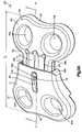
- FIG. 1Ais a perspective view of an embodiment of a contoured plate
- FIG. 1Bis another perspective view of the plate of FIG. 1A ;
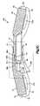
- FIG. 1Cis a partial cross-sectional view of the plate of FIG. 1B taken along the line B-B;
- FIG. 2Ais a perspective view of an embodiment of a securing plate
- FIG. 2Bis another perspective view of the plate of FIG. 2A ;
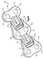
- FIG. 3Ais a perspective view of an embodiment of a one-level fixation assembly having a contoured plate and a securing plate, and in an expanded position;
- FIG. 3Bis another perspective view of the assembly of FIG. 3A ;
- FIG. 3Cis a cross-sectional view of the assembly of FIG. 3B taken along the line H-H;
- FIG. 3Dis an enlarged partial cross-sectional view of the assembly of FIG. 3B ;
- FIG. 4Ais a perspective view of the assembly of FIG. 3A in a compressed position
- FIG. 4Bis another perspective view of the assembly of FIG. 4A ;
- FIG. 5Ais a perspective view of an embodiment of a two-level fixation assembly including an intermediate plate
- FIG. 5Bis another perspective view of the assembly of FIG. 5B ;
- FIG. 6Ais a perspective view of another embodiment of a fixation assembly in a corpectomy arrangement
- FIG. 6Bis another perspective view of the plate of FIG. 6A ;
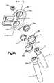
- FIG. 7Ais an exploded view of an embodiment of a fastener-securing assembly for use with a plate
- FIG. 7Bis a cross-sectional view of the assembly of FIG. 7A in assembled form, taken along the line F-F;
- FIG. 8Ais an exploded view of another embodiment of a fastener-securing assembly for use with a plate
- FIG. 8Bis a cross-sectional view of the assembly of FIG. 8A in assembled form, taken along the line G-G;
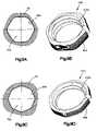
- FIG. 9Ais a top view of a hexagonal fastener hole for use with a plate
- FIG. 9Bis a perspective view of a hexagonal bushing for use with the fastener hole of FIG. 9A ;
- FIG. 9Cis a top view of a octagonal fastener hole for use with a plate.
- FIG. 9Dis a perspective view of an octagonal bushing for use with the fastener hole of FIG. 9C .
- the plates described hereinmay be used in spinal fusion procedures in which a damaged or diseased disc (or part of a disc) is removed from between a pair of vertebrae and a spinal fusion spacer is placed between the vertebrae.
- the platesmay be applied to an anterior portion of the affected vertebrae to span the affected disc space, and may be fixed to the vertebrae using bone screws.
- the platemay function to maintain the vertebrae aligned during the initial period following fixation in which fusion of the spacer to the adjacent vertebrae occurs.
- the platemay also function to share some of the axial spinal load applied to the fusion spacer to prevent extreme subsidence of the spacer into the vertebral body, such as where the patient has poor bone quality.
- the platesmay also act to prevent the spacer from being expelled from the disc space during the initial post-operative period.
- the platesmay be used for single level (i.e. one-disc) or multiple-level (i.e. multiple disc) fusion procedures. Some embodiments may be used for corpectomy procedures, in which at least a portion of a vertebral body is removed.
- Single level platesgenerally may have two pairs of bone screw holes, while the multi-level plates generally may have three or more pairs of holes. While the plates herein are described with reference and application to the spine, it will be appreciated that features of the plates and the plates may have other applications, and can be applied to other bones and/or parts of the skeleton.
- FIGS. 1A-4Bshow an embodiment of a one-level assembly, and the components thereof.
- FIGS. 1A-1Bshow views of a contoured plate 10 , which may have an upper surface 12 , a lower surface 14 , and a longitudinal axis A-A. Contoured plate 10 may also have an engaging end 16 and a fastening end 18 .
- the embodiment of contoured plate 10 shown in FIGS. 1A-1Bincludes two fastener holes 20 a , 20 b .
- Fastener holes 20 a , 20 bmay be configured to receive at least a portion of a bone fastener (see, e.g., FIGS.
- Upper and lower surfaces 12 , 14may be generally curved surfaces.
- Lower surface 14may have a radius of curvature R 1 at or near the fastening end 18 .
- Plate 10may also have a fastening width W 1 , which may be from about 2 mm to about 50 mm, and an engaging width W 2 , which may be from about 1 mm to about 50 mm.
- Plate 10may also have a window 22 extending from the upper surface 12 through the lower surface 14 .
- the window 22may be located near the engaging end 16 of the plate 10 .
- Window 22may be beneficial to reduce the overall weight of plate 10 , and/or provide visual access to a disc space below the plate 10 when implanted into a patient's body.
- Window 22may also provide access to tab 74 of securing plate 60 (discussed infra in detail), whereby a surgeon may use a tool or other instrument to manually urge the tab 74 . This procedure may serve as a way for a surgeon to reduce the amount of compression intraoperatively, as the surgeon may access tab 74 via window 22 sufficient to bend tab 74 and release tab 74 from a row of teeth.
- Plate 10may also have a recess 24 , located at or near the engaging end 16 .
- Recess 24may be appropriately shaped and sized to receive at least a portion of another plate element or desired structure, such as a securing plate 60 , discussed infra in relation to FIGS. 2A-2B .
- Recess 24may extend substantially over the engaging width W 2 of plate 10 .
- FIG. 1Bshows the lower surface 14 of plate 10 in more detail.
- Lower surface 14may have several features that may provide for various engagement options with another plate.
- Recess 24may be flanked by raised portions 26 a , 26 b , which may be beneficial to allow the recess 24 to have sufficient depth to receive a plate.
- the boundary of the recess 24may generally be raised edges 28 a , 28 b , from which the raised portions 26 a , 26 b may fall off into recess 24 .
- Raised edges 28 a , 28 bmay extend to side ledges 30 a , 30 b (not shown in FIG. 1B ), which may engage a slidably received plate.
- side stop surfaces 32 a , 32 bmay serve to control the transverse sliding of a received plate with respect to the longitudinal axis A-A of plate 10 , and may thereby maintain the correct orientation of received plate.
- Side ledges 30 a , 30 bmay terminate in engaging edges 34 a , 34 b (not shown in FIG. 1B ). A combination of these elements may assist in controlling the transverse sliding movement of a received plate (such as securing plate 60 , discussed infra).
- plate 10may also serve to control the longitudinal sliding movement of a received plate near or at recess 24 .
- Plate 10may have end stop surfaces 36 a , 36 b located at engaging end 16 , which may engage a corresponding surface on a received plate (i.e. end stop surfaces 94 a , 94 b of securing plate 60 , discussed infra).
- plate 10may also have an engaging stop surface 38 located near or at the end of recess 24 .
- Stop surfaces 36 a , 36 b , 38 , 40 , and 58may therefore, alone or in combination, assist in preventing a received plate from extending too far into plate 10 , and may therefore set a minimum length of a fixation assembly including plate 10 (see, e.g., FIGS. 4A-4B ).
- Plate 10may provide primary sliding surfaces 42 a , 42 b for sliding engagement with a received plate.
- primary sliding surfaces 42 a , 42 bshould corresponding to respective sliding surface of a received plate to ensure a sufficiently secure fit between plate 10 and a received plate.
- Plate 10may also have a series of teeth along the lower surface 14 within recess 24 .
- the embodiment of plate 10 shown in FIG. 1Bcontains three sets of two teeth 50 a , 50 b , 52 a , 52 b , and 54 a , 54 b , along with one set of ramped surfaces 56 a , 56 b .
- a contoured plate 10may have any suitable number of teeth and/or ramped surfaces to provide desired variable engagement locations for plate 10 and a received plate.
- plate 10may have two sets of teeth and two sets of ramped surfaces.
- plate 10may have four sets of teeth and no ramped surfaces. Teeth and/or ramped surfaces may or may not exist in sets. Teeth and/or ramped surfaces may exist in sets of two, three, or more. Other combinations will be appreciated by those skilled in the art.
- FIG. 1Cis a partial cross-sectional view of plate 10 taken along the line B-B.
- first tooth 50 ais substantially identical to first tooth 50 b , which comprise first set of teeth 50 a , 50 b . It should be noted that it may or may not be preferable to have sets of teeth comprised of individual teeth that are substantially identical.
- First set of teeth 50 a , 50 bmay have a length TL 1 , a height TH 1 , and may form an inclusive angle T ⁇ 1 .
- TL 1may be from about 0.1 mm to about 3 mm
- TH 1may be from about 0.1 mm to about 3 mm
- T ⁇ 1may be from about 30 degrees to about 90 degrees.
- second set of teeth 52 a , 52 bmay have a length TL 2 , a height TH 2 , and may form an inclusive angle T ⁇ 2 .
- TL 2may be from about 0.1 mm to about 3 mm
- TH 2may be from about 0.1 mm to about 3 mm
- T ⁇ 2may be from about 30 degrees to about 90 degrees.
- third set of teeth 54 a , 54 bmay have a length TL 3 , a height TH 3 , and may form an inclusive angle T ⁇ 3 .
- TL 3may be from about 0.1 mm to about 3 mm
- TH 3may be from about 0.1 mm to about 3 mm
- T ⁇ 3may be from about 30 degrees to about 90 degrees.
- FIG. 1Cshows a partial cross-sectional view of the plate 10 of FIG. 1B taken along the line B-B, and viewed from the far side of plate 10 .
- each toothmay have a base elevation and a peak elevation.
- first tooth 50 amay have a base elevation B 1 and a peak elevation P 1
- second tooth 52 amay have a base elevation B 2 and a peak elevation P 2
- third tooth 54 amay have a base elevation B 3 and a peak elevation P 3 .
- base elevations B 1 , B 2 , B 3rise progressively from the first tooth 50 b , to the second tooth 52 b , to the third tooth 54 b .
- peak elevations P 1 , P 2 , P 3may rise progressively from first tooth 50 b , to the second tooth 52 b , to the third tooth 54 b .
- the progressive rise in base and peak elevations in the direction of the first tooth 50 b toward the third tooth 54 bmay be advantageous to provide progressive resistance for an engaging element (such as tab 74 of securing plate 60 , discussed in detail infra), as a received plate is urged further into recess 24 of plate 10 . This relationship is discussed below in greater detail in relation to the assemblies of FIGS. 3A-4B .
- teeth heights TH 1 , TH 2 , TH 3are substantially equal, and teeth angles T ⁇ 1 , T ⁇ 2 , T ⁇ 3 are also substantially equal.
- teeth TL 1 , TL 2 , TL 3 lengthsare not substantially equal, which may be an incidental result of the relationships between base elevations B 1 , B 2 , B 3 and peak elevations P 1 , P 2 , P 3 of plate 10 .
- the teeth heights and angles shown in FIG. 1Care substantially identical, and the teeth lengths are substantially different, it may be preferable to have teeth with different heights, lengths, and/or angles within the recess 24 of plate 10 .
- teethmay have progressively smaller or larger heights, lengths, and/or angles, which may provide further increased or decreased resistance to a received plate. It is expressly contemplated that all three aspects of the teeth (length, height, and inclusive angle) may be varied by those skilled in the art to provide a desired engagement structure within recess 24 of plate 10 for engagement with a received plate.
- FIG. 1Calso shows first tooth 50 b having a slightly different shape than that of second and third teeth 52 b , 54 b .
- Such variations in shapemay be beneficial to promote increased or decreased progressive resistance, and/or to provide a more secure fit for a desired engagement structure, such as a tab 74 .
- the shape of the first, second, and third set of teeth 50 a , 50 b , 52 a , 52 b , 54 a , 54 bin addition to ramped surfaces 56 a , 56 b , may be varied by those skilled in the art. It may be beneficial for all sets to teeth to have the same shape, or vary the shapes of the teeth.
- FIG. 1Calso shows a ramped surface representative of both ramped surfaces 56 a , 56 b , which may generally follow the last row of teeth (in this case, third set of teeth 54 a , 54 b ).
- Ramped surfaces 56 a , 56 bmay not provide a level of resistance equal to that provided by teeth 50 a , 50 b , 52 a , 52 b , 54 a , 54 b , but may provide some level of resistance before a received plate reaches curved stop surface 40 .
- Ramped surfacemay have a length RL.
- FIGS. 2A-2Bshow views of a securing plate 60 , which may have an upper surface 62 , a lower surface 64 , and a longitudinal axis C-C. Securing plate 60 may also have an engaging end 66 and a fastening end 68 . Like contoured plate 10 , the embodiment of securing plate 60 shown in FIGS. 2A-2B include two fastener holes 70 a , 70 b . Fastener holes 70 a , 70 b may be configured to receive at least a portion of a bone fastener (see, e.g., FIGS. 7A-8B , discussed infra), which may be inserted into a bone segment, such as a vertebral body.
- a bone fastenersee, e.g., FIGS. 7A-8B , discussed infra
- Upper and lower surfaces 62 , 64may be generally curved surfaces. Lower surface 64 may have a radius of curvature R 2 at or near the fastening end 68 . Plate 60 may also have a fastening width W 3 , which may be from about 2 mm to about 50 mm, and an engaging width W 4 , which may be from about 1 mm to about 50 mm.
- Plate 60may also have a window 72 extending from the upper surface 62 through the lower surface 64 .
- the window 72again may be located near the engaging end of the plate 60 .
- Window 72may be beneficial to reduce the overall weight of plate 60 , and/or provide visual access to a disc space below the plate 60 when implanted into a patient's body. As seen in FIGS. 3A-4B , windows 22 and 72 may align when plates 10 and 60 engage.
- a portion of securing plate 60may be configured to engage contoured plate 10 , and plate 60 may contain several features for engagement.
- Plate 60may have a securing element 74 , which may have an enlarged tab 76 and an engaging ridge 78 .
- Securing element 74may also have a end surface 80 , and side surfaces 82 a , 82 b .
- securing element 74may be a resilient structure that is deflectable between a range of positions to engage at least one corresponding structure on another plate.
- securing element 74may be designed to engage a series of teeth or ramped surface of plate 10 when securing plate 60 is inserted into recess 24 .
- the engaging ridge 78may provide a sufficient contour to engage such teeth, as shown in FIGS. 3A-4B .
- Securing elementmay be deflectable around axis D-D.
- Securing element 74may be separated from a portion of plate 60 by channel 84 , leaving end surface 80 and side surfaces 82 a , 82 b exposed. This arrangement may allow for increased flexibility of the securing element 74 .
- plate 60may have a leading groove 86 , which may engage a sidewall of the primary sliding surface 42 (see FIG. 3B ). Inner surface 88 may engage the primary sliding surface 42 in a similar manner.
- Plate 60may also have protrusions 90 a , 90 b located on sliding side surfaces 92 a , 92 b disposed between upper and lower surfaces 62 , 64 . Protrusions 90 a , 90 b and sliding side surfaces 92 a , 92 b may engage side ledges 30 a , 30 b and side stop surfaces 32 a , 32 b of plate 10 when plate 60 is slidingly engaged with plate 10 .
- these sliding elements 86 , 88 , 90 a , 90 b , 92 a , and 92 b of plate 60may assist in controlling the transverse sliding movement of securing plate 60 as it engages plate 10 .
- Protrusions 90 a , 90 bmay be especially useful in maintaining the proper alignment of plate 60 as it engages plate 10 .
- side ledges 30 a , 30 b and/or side stop surfaces 32 a , 32 b of plate 10may also serve an important role in maintaining the proper alignment of plates 10 and 60 .
- Securing plate 60may similarly have structures that may assist in limiting the longitudinal translation of plate 60 within the recess 24 of contoured plate 10 .
- End stop surfaces 94 a , 94 bmay abut end stop surfaces 36 a , 36 b when securing plate 60 has reached a maximum translation within the recess 24 of contoured plate 10 .
- curved surfaces 96 a , 96 b and end edges 98 a , 98 bmay engage engaging stop surface 38 , curved stop surface 40 , and/or angled end surface 58 when securing plate 60 has reached a maximum translation within the recess 24 of contoured plate 10 .
- Stop surfaces 94 a , 94 b , 96 a , 96 b , 98 a , and 98 bmay therefore, alone or in combination, assist in preventing securing plate 60 from extending too far into contoured plate 10 , and may therefore set a minimum length of a fixation assembly comprising plates 10 and 60 .
- assemblies 100 of FIGS. 4A-4Bshown in a compressed state, may not result in stop surfaces 36 a , 36 b of contoured plate 10 abutting stop surfaces 94 a , 94 b of securing plate 60 . It may still be beneficial to have such stop surfaces, however, as plates 10 and 60 may come in different sizes and dimensions so that stop surfaces 36 a , 36 b do abut stop surfaces 94 a , 94 b when assembly 100 is in a compressed state.
- FIGS. 3A-4Bshow views of fixation assembly 100 comprising a contoured plate 10 and securing plate 60 and having a longitudinal axis E-E.
- FIGS. 3A-3Bshow the assembly 100 in an expanded state, wherein the securing element 74 of plate 60 is engaging the first set of teeth 50 a , 50 b .
- assembly 100may have a length L E , which may be from about 10 mm to about 200 mm.
- FIGS. 4A-4Bshow the assembly 100 in a compressed state, wherein the securing element 74 of plate 60 engages third set of teeth 54 a , 54 b .
- assembly 100may have a length L C , which may be from about 5 mm to about 200 mm.
- FIGS. 3C-3Dmore particularly show the engagement between plates 10 and 60 .
- FIG. 3Cis a cross-sectional view of the assembly 100 of FIG. 3B . The engagement of tab 74 with first tooth 50 b is evident by FIG. 3C .
- FIG. 3Calso shows a portion of securing plate 60 received within recess 24 of contoured plate 10 .
- FIG. 3Dis an enlarged partial cross-sectional view of the assembly 100 of FIG. 3B , showing the engagement of plates 10 and 60 in greater detail.
- a surgeonshould attach assembly 100 to adjacent vertebrae when the assembly is in an expanded state.
- the surgeonmay choose to manually compress the assembly 100 intraoperatively, as discussed above.
- Post-operativelyas the vertebrae move toward each other, and as the spacer resorps into the endplates of the vertebrae (if the spacer is made from a resorbable material, such as bone), there may be forces exerted on the assembly 100 urging plates 10 and 60 toward one another.
- the engagement relationship between the enlarged tab 76 and engaging ridge 78 of the securing element 74 and the teeth 50 a , 50 b , 52 a , 52 b , 54 a , 54 b and ramped surfaces 56 a , 56 bis such that relative extension and disengagement of contoured plate 10 and securing plate 60 is prevented.
- This featuremay be beneficial to prevent post-operative expansion and/or separation of assembly 100 , which may be undesirable in light of the risks of spacer expulsion from the disc space and/or vertebral release. More importantly, this feature may also be advantageous to maintain compression on the affected intervertebral space and accompanying graft spacer, to promote fusion.
- FIGS. 5A-5Bshow another embodiment of a fixation assembly utilizing the variable compressive features of plates 10 and 60 described above.
- Assembly 200is a two-level assembly, that may comprise a contoured plate 110 , a securing plate 160 , and an intermediate plate 210 .
- Contoured plate 110may have an upper surface 112 , lower surface 114 , engaging end 116 , fastening end 118 , and fastener holes 120 a , 120 b .
- securing plate 160may have an upper surface 162 , lower surface 164 , engaging end 166 , fastening end 168 , and fastener holes 170 a , 170 b . As shown in the embodiment shown in FIGS.
- intermediate plate 210may be positioned between plates 110 and 160 so as to engage both plates. Moreover, intermediate plate 210 may have an upper surface 212 , a lower surface 214 . The embodiment of the intermediate plate 210 shown in FIGS. 5A-5B additionally has two fastener holes 220 a , 220 b , which may exhibit any or all of the characteristics and/or functions of fastener holes described above.
- Intermediate plate 210may also have a first engaging end 216 a , a second engaging end 216 b , with a fastening portion 218 disposed therebetween. As shown in FIGS. 5A-5B , first engaging end 216 a and surrounding area of intermediate plate 210 may substantially mimic the characteristics and functions of the securing plate 60 , 160 , discussed above. Similarly, the second engaging end 216 b and surrounding area of intermediate plate 210 may substantially mimic the characteristics and functions of the contoured plate 10 , 110 , also discussed above.
- Assembly 200may be useful in applications where more than two vertebrae require fixation. While assembly 200 is configured to be used in a two-level assembly, fastening three adjacent vertebrae, it is expressly contemplated that assembly 200 may be configured in a three-level, four-level, or other multi-level assembly to sufficiently meet desired fixation objectives. Contoured plate 110 and securing plate 160 may have any or all of the characteristics and functions of corresponding plates 10 and 60 , as described in detail above.
- FIGS. 6A-6Bshow another embodiment a fixation assembly utilizing the variable compressive features of plates 10 and 60 described above.
- Assembly 300is configured in a corpectomy model, wherein the assembly 300 is designed to span a space including at least one removed vertebrae, and may comprise a contoured plate 310 and a securing plate 360 .
- Contoured plate 310may have an upper surface 312 , lower surface 314 , engaging end 316 , fastening end 318 , and fastener holes 320 a , 320 b .
- Contoured plate 310may also have an elongated body portion 311 extending between engaging end 316 and fastening end 318 .
- Securing plate 360may likewise have an upper surface 362 , lower surface 364 , engaging end 366 , fastening end 368 , and fastener holes 370 a , 370 b .
- Securing platemay also have an elongated body portion 361 extending between engaging end 366 and fastening end 368 , and may have a securing element 374 which may have any or all of the characteristics of securing element 74 described in relation to securing plate 60 , described above.
- contoured plate 310 and securing plate 360may have any or all of the characteristics and functions of corresponding plates 10 and 60 , as described in detail above.
- Assembly 300may be beneficial in corpectomy procedures to provide a more streamlined assembly with a lower profile, as attachment to intermediate vertebrae is unnecessary because the have been at least partially removed.
- Body portions 311 , 361therefore may serve to effectively span the length between attached vertebrae without unnecessary fastener holes or other features.
- FIGS. 7A-7Bshow an embodiment of a fastener-securing assembly for use with any or all of the plates 10 , 60 , 110 , 160 , 210 , 310 , 360 described above.
- FIG. 7Ashows an exploded view of the assembly as used with securing plate 60 .
- securing plate 60has a fixation hole 71 located between fastener holes 70 a , 70 b , and extending from the upper surface 62 through the lower surface 64 .
- Fixing element 75 having a threaded bore 77may be disposed within plate 60 , such that fixing element 75 may be disposed between fastener holes 70 a , 70 b , and threaded bore 77 may substantially align with fixation hole 71 .
- Fixing element 75may also have ramped surfaces 67 a , 67 b which may generally slope downwards, as seen in FIG. 7B .
- Fastener holes 70 a , 70 bmay be fitted with bushings 79 a , 79 b , that may allow for the polyaxial angulation of fasteners 81 a , 81 b when the heads 83 a , 83 b of the fasteners are placed within fastener holes 70 a , 70 b.
- Fasteners 81 a , 81 b and platesmay be “variable angle” or “fixed angle.” “Variable angle” refers to fasteners and/or plates for which: (1) the trajectory of insertion of the fastener into bone (through a fastener hole in the plate) may be selected by the surgeon (although only a limited range of motion may be permitted); and/or (2) the trajectory of the fastener with respect to the plate is allowed to change following insertion into bone, for example to toggle to accommodate any translational and/or rotational settling that occur post-operatively between the plate and the fastener that has been rigidly placed into a vertebral body (although only a limited range of motion may be permitted).
- “Fixed angle”refers to fasteners and/or plates for which: (1) the trajectory of insertion of the fastener into bone (through a fastener hole in the plate) is pre-selected and thus fixed; and/or (2) the trajectory of the fastener with respect to the plate is not allowed to change following insertion into bone.
- fasteners 81 a , 81 bmay be inserted into fastener holes 70 a , 70 b such that heads 83 a , 83 b contact bushings 79 a , 79 b .
- a rivet 73may be inserted into fixation hole 71 .
- Rivet 73may have threads 69 capable of engaging the threaded bore 77 . As rivet 73 is inserted into fixation hole 71 , threads 69 may threadedly engage threaded bore 77 , urging the fixing element 75 upward toward the upper surface 62 of plate 60 .
- ramped surfaces 67 a , 67 bmay engage the outer surface of bushings 79 a , 79 b , thereby applying a compressive, radial force on the bushings 79 a , 79 b , which therefore may secure heads 83 a , 83 b in the desired orientation within fastener holes 70 a , 70 b.
- fasteners 81 a , 81 bmay be beneficial to secure the orientation of fasteners 81 a , 81 b in a fixed relation to a plate and/or assembly for at least the reason of preventing post-operative fastener back-out.
- Forces within the spinal columnmay tend to urge inserted fasteners out of vertebral bodies, which may in turn lead to unwarranted and undesirable instability of a plate and/or assembly after implantation.
- the fastener-securing assembly described abovemay assist in preventing fastener back-out.
- FIGS. 8A-8BAnother embodiment of a fastener-securing assembly is shown in FIGS. 8A-8B .
- This embodimentis substantially similar in structure to the embodiment shown in FIGS. 7A-7B , but includes a different fixing element 85 with correspondingly different features.
- fixing element 85may have a threaded bore 89 that, when fixing element is disposed within plate 60 , may be substantially aligned with fixation hole 71 .
- fixing element 85 in this embodimenthas fastener holes 87 a , 87 b that may substantially align with fastener holes 70 a , 70 b .
- Fixing element 85also may have ramped surfaces 93 a , 93 b , 93 c , 93 d that may engage bushings 79 a , 79 b . In the embodiment shown in FIGS. 8A-8B , fixing element 85 also may be disposed relatively lower within plate 60 , as compared to fixing element 75 , previously described.
- fixing element 85may be urged upwards into contact with bushings 79 a , 79 b .
- ramped surfaces 93 a , 93 b , 93 c , 93 dmay engage bushings 79 a , 79 b , such that the fixing element 75 may apply a compressive, radial force on the bushings 79 a , 79 b , which therefore may secure heads 83 a , 83 b in the desired orientation within fastener holes 70 a , 70 b.
- fastener securing assembliesmay be utilized in assemblies wherein fasteners 81 a , 81 b are inserted into a vertebrae through the fastener holes 70 a , 70 b of a pre-placed plate 60 , or in the alternative, plate 60 may be lowered into engagement with fasteners 81 a , 81 b after the fasteners have already been inserted into a vertebrae. It may be beneficial to first attach fasteners 81 a , 81 b , and then apply plate 60 for at least the reason of utilizing the fastener heads 83 a , 83 b during vertebral distraction techniques prior to graft insertion. Again, these alternatives also apply to each plate 10 , 60 , 110 , 160 , 210 , 310 , 360 described herein.
- FIGS. 9A-9Dshow variations of fastener holes and accompanying bushings for use with any plate described herein.
- the fastener holes 70 a and accompanying upper surface 62are described in relation to securing plate 60 , by way of example. While several of the fastener holes 70 a et al. are shown to be substantially circular, it may be preferable to have such fastener holes be a polygonal shape, such as hexagonal (see FIG. 9A ) or octagonal (see FIG. 9C ). Moreover, a fastener hole 70 a may also be fitted with a bushing, regardless of the particular shape of the fastener hole.
- bushingsmay be beneficial to allow a fastener 81 a , 81 b to toggle and/or rotate within a fastener hole so that a fastener may be inserted at a desired angle.
- Bushing 79 b(discussed supra) demonstrates this advantage with respect to inserted fastener 81 b.
- FIG. 9Bshows a hexagonal bushing 400 with inner threads 402 a and an outer surface 404 that may be fitted within fastener hole 70 a of FIG. 9A .
- the outer surface 404 of bushing 400may lie substantially adjacent the inner surface 99 a of fastener hole 70 a .
- FIG. 9Dshows an octagonal bushing 410 with inner threads 402 b and an outer surface 406 that may be fitted within fastener hole 70 a of FIG. 9C .
- the outer surface 406 of bushing 410may also lie substantially adjacent the inner surface 99 b of fastener hole 70 a .
- Each of the fasteners, plates, and other components disclosed hereinmay be formed of a titanium alloy such as titanium-aluminum-niobium, which may be anodized.
- a titanium alloysuch as titanium-aluminum-niobium, which may be anodized.
- One material for use with each of the plates and screws described hereinis Ti-6Al-7Nb, with a density of about 4.52 gm/cc, a modulus of elasticity of about 105 GPa, an ultimate tensile strength of about 900 MPa, and a yield strength of about 800 MPa.
- Surfaces of the fastenersmay also be burr free, with all sharp edges having a radius to a maximum of about 0.1 mm. It is expressly contemplated that each of the fasteners, plates, and other components may be comprised of other suitable materials, in addition to the one mentioned herein, as desired by those skilled in the art.
Landscapes
- Health & Medical Sciences (AREA)
- Orthopedic Medicine & Surgery (AREA)
- Life Sciences & Earth Sciences (AREA)
- Surgery (AREA)
- Neurology (AREA)
- Heart & Thoracic Surgery (AREA)
- Engineering & Computer Science (AREA)
- Biomedical Technology (AREA)
- Nuclear Medicine, Radiotherapy & Molecular Imaging (AREA)
- Medical Informatics (AREA)
- Molecular Biology (AREA)
- Animal Behavior & Ethology (AREA)
- General Health & Medical Sciences (AREA)
- Public Health (AREA)
- Veterinary Medicine (AREA)
- Prostheses (AREA)
- Surgical Instruments (AREA)
Abstract
Description
Claims (8)
Priority Applications (12)
| Application Number | Priority Date | Filing Date | Title |
|---|---|---|---|
| US11/001,902US7635364B2 (en) | 2004-12-01 | 2004-12-01 | Unidirectional translation system for bone fixation |
| BRPI0518727-3ABRPI0518727A2 (en) | 2004-12-01 | 2005-11-30 | securing arrangement, and method for securing a plurality of bone segments |
| AU2005311887AAU2005311887A1 (en) | 2004-12-01 | 2005-11-30 | Unidirectional translation system for bone fixation |
| AT05848882TATE537770T1 (en) | 2004-12-01 | 2005-11-30 | UNIDIRECTIONAL TRANSLATION SYSTEM FOR BONE FIXATION |
| NZ555463ANZ555463A (en) | 2004-12-01 | 2005-11-30 | Unidirectional translation system for bone fixation with interengaging teeth for resilient engagement |
| JP2007544474AJP5166035B2 (en) | 2004-12-01 | 2005-11-30 | Unidirectional linear movement system for bone fixation |
| PCT/US2005/043359WO2006060506A1 (en) | 2004-12-01 | 2005-11-30 | Unidirectional translation system for bone fixation |
| KR1020077014232AKR101166783B1 (en) | 2004-12-01 | 2005-11-30 | Unidirectional translation system for bone fixation |
| CA2589434ACA2589434C (en) | 2004-12-01 | 2005-11-30 | Unidirectional translation system for bone fixation |
| CNB2005800471051ACN100563589C (en) | 2004-12-01 | 2005-11-30 | Unidirectional Transfer System for Bone Fixation |
| EP05848882AEP1838231B1 (en) | 2004-12-01 | 2005-11-30 | Unidirectional translation system for bone fixation |
| ZA200704525AZA200704525B (en) | 2004-12-01 | 2005-11-30 | Unidirectional translation system for bone fixation |
Applications Claiming Priority (1)
| Application Number | Priority Date | Filing Date | Title |
|---|---|---|---|
| US11/001,902US7635364B2 (en) | 2004-12-01 | 2004-12-01 | Unidirectional translation system for bone fixation |
Publications (2)
| Publication Number | Publication Date |
|---|---|
| US20060116683A1 US20060116683A1 (en) | 2006-06-01 |
| US7635364B2true US7635364B2 (en) | 2009-12-22 |
Family
ID=36121325
Family Applications (1)
| Application Number | Title | Priority Date | Filing Date |
|---|---|---|---|
| US11/001,902Expired - Fee RelatedUS7635364B2 (en) | 2004-12-01 | 2004-12-01 | Unidirectional translation system for bone fixation |
Country Status (12)
| Country | Link |
|---|---|
| US (1) | US7635364B2 (en) |
| EP (1) | EP1838231B1 (en) |
| JP (1) | JP5166035B2 (en) |
| KR (1) | KR101166783B1 (en) |
| CN (1) | CN100563589C (en) |
| AT (1) | ATE537770T1 (en) |
| AU (1) | AU2005311887A1 (en) |
| BR (1) | BRPI0518727A2 (en) |
| CA (1) | CA2589434C (en) |
| NZ (1) | NZ555463A (en) |
| WO (1) | WO2006060506A1 (en) |
| ZA (1) | ZA200704525B (en) |
Cited By (33)
| Publication number | Priority date | Publication date | Assignee | Title |
|---|---|---|---|---|
| US20080140128A1 (en)* | 2006-12-08 | 2008-06-12 | Trimax Medical Management, Inc. | Sternal Closure Device and Method of Using Same |
| US20090163960A1 (en)* | 2007-11-21 | 2009-06-25 | Lawrence Binder | Cervical spine stabilization system with extendable plates |
| US20100042160A1 (en)* | 2008-08-06 | 2010-02-18 | Ashok Biyani | Cervical plate assembly |
| US20100076495A1 (en)* | 2006-03-08 | 2010-03-25 | Lindemann Gary S | Flexible bone plates and methods for dynamic spinal stabilization |
| US20100198221A1 (en)* | 2007-08-20 | 2010-08-05 | Synthes USA , LLC | Ratcheting Epiphysiodesis Plate |
| US20110004255A1 (en)* | 2009-02-19 | 2011-01-06 | Nextremity Solutions, Llc | Bone joining apparatus and method |
| WO2011116364A1 (en)* | 2010-03-19 | 2011-09-22 | Nextremity Solutions, Llc | Dynamic bone plate |
| US20120095466A1 (en)* | 2010-10-19 | 2012-04-19 | Biomet Manufacturing Corp. | Orthopedic Plate Assembly for a Distal Radius Having Re-Contouring Features and Method for Using Same |
| US20140107712A1 (en)* | 2012-10-12 | 2014-04-17 | Smith & Nephew, Inc. | Fusion implant |
| US8771324B2 (en) | 2011-05-27 | 2014-07-08 | Globus Medical, Inc. | Securing fasteners |
| WO2015065915A1 (en)* | 2013-10-28 | 2015-05-07 | Jace Medical, Llc | Orthopaedic fixation devices, systems and methods |
| US9028498B2 (en) | 2013-03-14 | 2015-05-12 | Innovasis, Inc. | Modular bone fixation plate assembly |
| US9072562B2 (en) | 2009-02-19 | 2015-07-07 | Nextremity Solutions, Inc. | Bone joining device, kit and method |
| USD734853S1 (en) | 2009-10-14 | 2015-07-21 | Nuvasive, Inc. | Bone plate |
| US9095387B2 (en) | 2011-04-13 | 2015-08-04 | Globus Medical, Inc. | Spine stabilization |
| US9468479B2 (en) | 2013-09-06 | 2016-10-18 | Cardinal Health 247, Inc. | Bone plate |
| US9468465B2 (en) | 2009-02-19 | 2016-10-18 | Nextremity Solutions, Inc. | Reversible bone coupling device and method |
| US9615866B1 (en) | 2004-10-18 | 2017-04-11 | Nuvasive, Inc. | Surgical fixation system and related methods |
| US20170172636A1 (en)* | 2015-12-16 | 2017-06-22 | Neos Surgery, S.L. | Sternal Closure Assembly |
| US20170181779A1 (en)* | 2015-12-29 | 2017-06-29 | Orthohelix Surgical Designs, Inc. | Active compression plate and method for its use |
| US9801671B2 (en) | 2013-07-11 | 2017-10-31 | Stryker European Holdings I, Llc | Fixation assembly with multiple sections for securing parts of a sternum |
| US9968390B2 (en) | 2011-09-14 | 2018-05-15 | Zimmer Gmbh | Bone fixing apparatus |
| US10028843B2 (en)* | 2012-05-07 | 2018-07-24 | Smith & Nephew, Inc. | Compaction pliers having removable cutting inserts |
| US10292743B2 (en) | 2012-03-01 | 2019-05-21 | Wright Medical Technology, Inc. | Surgical staple |
| US11039865B2 (en) | 2018-03-02 | 2021-06-22 | Stryker European Operations Limited | Bone plates and associated screws |
| US20210196327A1 (en)* | 2019-12-25 | 2021-07-01 | Apifix Ltd. | Biasing device for spinal device |
| US11103239B2 (en)* | 2017-04-21 | 2021-08-31 | Biomet Manufacturing, Llc | Ratchet staple |
| US11123117B1 (en)* | 2011-11-01 | 2021-09-21 | Nuvasive, Inc. | Surgical fixation system and related methods |
| US20220015751A1 (en)* | 2018-11-16 | 2022-01-20 | Small Bone Lengthening Llc | Bone distraction devices and methods of using same |
| US11259853B2 (en) | 2015-01-09 | 2022-03-01 | Stryker European Operations Holdings Llc | Implant for bone fixation |
| US11596458B2 (en) | 2016-11-11 | 2023-03-07 | Stryker European Operations Holdings Llc | Implant for bone fixation |
| US11660133B2 (en) | 2018-10-26 | 2023-05-30 | Zimmer, Inc. | Bone coupling device and method |
| US12185996B2 (en) | 2014-08-20 | 2025-01-07 | Biomet Microfixation, Llc | Implant positioning devices and methods |
Families Citing this family (29)
| Publication number | Priority date | Publication date | Assignee | Title |
|---|---|---|---|---|
| US20060129151A1 (en)* | 2002-08-28 | 2006-06-15 | Allen C W | Systems and methods for securing fractures using plates and cable clamps |
| US7306605B2 (en) | 2003-10-02 | 2007-12-11 | Zimmer Spine, Inc. | Anterior cervical plate |
| US8118847B2 (en)* | 2005-03-08 | 2012-02-21 | K2M, Inc. | Anterior vertebral plate with underside locking mechanism |
| US8070749B2 (en) | 2005-05-12 | 2011-12-06 | Stern Joseph D | Revisable anterior cervical plating system |
| WO2007098188A2 (en)* | 2006-02-21 | 2007-08-30 | Life Spine, Inc. | Structure for joining and retaining multi-part orthopedic implants |
| US8262710B2 (en)* | 2006-10-24 | 2012-09-11 | Aesculap Implant Systems, Llc | Dynamic stabilization device for anterior lower lumbar vertebral fusion |
| US8206390B2 (en)* | 2006-11-02 | 2012-06-26 | Warsaw Orthopedic, Inc. | Uni-directional ratcheting bone plate assembly |
| US20090043341A1 (en)* | 2007-08-09 | 2009-02-12 | Aesculap, Inc. | Dynamic extension plate for anterior cervical fusion and method of installation |
| US8388663B2 (en) | 2007-09-13 | 2013-03-05 | Stryker Spine | Dynamic cervical plate |
| WO2009039430A1 (en)* | 2007-09-19 | 2009-03-26 | Stout Medical Group, L.P. | Implantable support device and method of use |
| US8343154B2 (en)* | 2007-09-26 | 2013-01-01 | Biomet C.V. | Modular bone plate system |
| US20090210008A1 (en)* | 2008-02-20 | 2009-08-20 | Life Spine, Inc. | Modular spine plate with projection and socket interface |
| US8425514B2 (en) | 2008-06-25 | 2013-04-23 | Westmark Medical, Llc. | Spinal fixation device |
| WO2010025405A1 (en)* | 2008-08-29 | 2010-03-04 | Life Spine, Inc. | Single-sided dynamic spine plates |
| WO2010065666A1 (en) | 2008-12-02 | 2010-06-10 | Eminent Spine Llc | Bone plate and plating system for use of same |
| JP5580403B2 (en)* | 2009-04-23 | 2014-08-27 | ジンテス ゲゼルシャフト ミット ベシュレンクテル ハフツング | Applicable bone fixation plate |
| US8382842B2 (en)* | 2009-05-14 | 2013-02-26 | Stout Medical Group, L.P. | Expandable support device and method of use |
| DE102009055826A1 (en)* | 2009-11-25 | 2011-05-26 | Universitätsklinikum Jena | Device for plate osteosynthesis, has plate system with multiple application specific, stacked, lockable, uniform or curved individual plates of different forms and sizes |
| WO2011109610A2 (en)* | 2010-03-03 | 2011-09-09 | Lanx, Inc. | Bone plating system and method |
| US10342583B2 (en)* | 2010-10-01 | 2019-07-09 | K2M, Inc. | Dynamic plate with inserts |
| US20140088654A1 (en)* | 2011-06-01 | 2014-03-27 | Alfred Health | Bone Splint |
| JP6214011B2 (en)* | 2012-05-10 | 2017-10-18 | スパイナル シンプリシティ エルエルシーSpinal Simplicity LLC | Dynamic fracture plate |
| US9579128B2 (en) | 2013-07-19 | 2017-02-28 | K2M, Inc. | Translational plate and compressor instrument |
| CN104287818B (en)* | 2014-10-29 | 2017-04-19 | 刘忠军 | Length-adjustable vertebral plate |
| US10792077B2 (en)* | 2015-10-01 | 2020-10-06 | Orion Spine Inc. | Spine protection device |
| GB201605087D0 (en)* | 2016-03-24 | 2016-05-11 | Apio Implants Ltd | Bone Ties and staples for use in orthopaedic surgery |
| CN107550554B (en)* | 2017-08-24 | 2020-09-01 | 北京爱康宜诚医疗器材有限公司 | Steel plate structure |
| KR102153397B1 (en)* | 2018-08-27 | 2020-09-08 | 주식회사 아이키 | Medical bone plate enabling to improve bending strength |
| CN113262032B (en)* | 2021-06-17 | 2024-10-22 | 北京爱康宜诚医疗器材有限公司 | Bone fixing plate and bone fixing plate assembly with same |
Citations (62)
| Publication number | Priority date | Publication date | Assignee | Title |
|---|---|---|---|---|
| US3547114A (en) | 1967-07-07 | 1970-12-15 | Edward J Haboush | Compensating plate means for bone fractures |
| US3604414A (en) | 1968-08-29 | 1971-09-14 | Nicomedes Borges | Bone setting device |
| US3606414A (en)* | 1969-08-22 | 1971-09-20 | Osmose Wood Preserving Co | Fastener |
| US3659595A (en) | 1969-10-22 | 1972-05-02 | Edward J Haboush | Compensating plates for bone fractures |
| US3950001A (en)* | 1973-07-04 | 1976-04-13 | Gertsch Ag | Adjusting mechanism for ski bindings |
| US4157715A (en) | 1977-03-25 | 1979-06-12 | Erhard Westerhoff | Intracorporal drive to produce a continuous traction or pressure and method of operating the same |
| JPH0263455A (en) | 1988-06-18 | 1990-03-02 | Howmedica Internatl Inc Zweignied Kiel | Bone plate |
| US5190544A (en)* | 1986-06-23 | 1993-03-02 | Pfizer Hospital Products Group, Inc. | Modular femoral fixation system |
| US5234431A (en) | 1991-04-03 | 1993-08-10 | Waldemar Link Gmbh & Co. | Bone plate arrangement |
| US5344421A (en) | 1993-07-16 | 1994-09-06 | Amei Technologies Inc. | Apparatus and method for adjusting a bone plate |
| US5470333A (en) | 1993-03-11 | 1995-11-28 | Danek Medical, Inc. | System for stabilizing the cervical and the lumbar region of the spine |
| US5484439A (en) | 1992-09-16 | 1996-01-16 | Alphatec Manufacturing, Inc. | Modular femur fixation device |
| WO1996014802A1 (en) | 1994-11-10 | 1996-05-23 | Georges Kehyayan | Device for temporarily locking two portions of a bone |
| US5531745A (en) | 1993-03-11 | 1996-07-02 | Danek Medical, Inc. | System for stabilizing the spine and reducing spondylolisthesis |
| WO1996032072A1 (en) | 1995-04-11 | 1996-10-17 | Plaza Fernandez Rafael De | Linear expander for the progressive correction of craniofacial deformations |
| US5616142A (en) | 1994-07-20 | 1997-04-01 | Yuan; Hansen A. | Vertebral auxiliary fixation device |
| EP0773004A1 (en) | 1995-11-07 | 1997-05-14 | IMPLANTS ORTHOPEDIQUES TOUTES APPLICATIONS, S.A.R.L. dite: | Osteotomy plate for angle correction |
| WO1997020512A1 (en) | 1995-12-01 | 1997-06-12 | Walker David A | Telescopic bone plate for use in bone lenghtening by distraction osteogenesis |
| US5672177A (en) | 1996-01-31 | 1997-09-30 | The General Hospital Corporation | Implantable bone distraction device |
| US5681313A (en) | 1995-02-06 | 1997-10-28 | Karl Leibinger Medizintechnik Gmbh & Co. Kg | Device for the extension of bones |
| US5728099A (en) | 1994-02-21 | 1998-03-17 | Collux A.B. | Implant |
| EP0829240A1 (en) | 1996-09-17 | 1998-03-18 | Jürgen Prof. Dr. Harms | Bone plate |
| US5827286A (en) | 1997-02-14 | 1998-10-27 | Incavo; Stephen J. | Incrementally adjustable tibial osteotomy fixation device and method |
| US5842822A (en)* | 1996-07-19 | 1998-12-01 | Everett Industries Inc | Removable quasi-ratchet fastener |
| WO1999004718A1 (en) | 1997-07-28 | 1999-02-04 | Dimso (Distribution Medicale Du Sud-Ouest) | Implant, in particular front cervical plate |
| EP0904740A2 (en) | 1997-09-29 | 1999-03-31 | OLERUD, Sven | Implant with bone screw insert |
| US6051007A (en) | 1998-03-02 | 2000-04-18 | Corvascular, Inc. | Sternal closure device and instruments therefor |
| US6126660A (en) | 1998-07-29 | 2000-10-03 | Sofamor Danek Holdings, Inc. | Spinal compression and distraction devices and surgical methods |
| FR2796829A1 (en) | 1999-07-30 | 2001-02-02 | Georges Kehyayan | System for temporary fixing of two part of bone comprises a guide bar with teeth working together with teeth of slide block |
| US6277124B1 (en) | 1999-10-27 | 2001-08-21 | Synthes (Usa) | Method and apparatus for ratcheting adjustment of bone segments |
| US6302883B1 (en) | 1998-10-22 | 2001-10-16 | Depuy Acromed, Inc. | Bone plate-ratcheting compression apparatus |
| US6328738B1 (en) | 1999-11-24 | 2001-12-11 | Loubert Suddaby | Anterior cervical fusion compression plate and screw guide |
| US20020016595A1 (en) | 1999-05-05 | 2002-02-07 | Gary K. Michelson | Screws of cortical bone and method of manufacture thereof |
| US20020055741A1 (en) | 1999-05-14 | 2002-05-09 | Schlapfer Fridolin J. | Bone fixation device with a rotation joint |
| EP1205154A2 (en) | 2000-11-08 | 2002-05-15 | Aesculap AG & Co. KG | Osteosynthesis plating apparatus and method with extension plate |
| US6402756B1 (en) | 2001-02-15 | 2002-06-11 | Third Millennium Engineering, Llc | Longitudinal plate assembly having an adjustable length |
| US6432108B1 (en) | 2000-01-24 | 2002-08-13 | Depuy Orthopaedics, Inc. | Transverse connector |
| US20020111630A1 (en) | 2001-02-15 | 2002-08-15 | Ralph James D. | Longitudinal plate assembly having an adjustable length |
| US20020143336A1 (en) | 2001-02-23 | 2002-10-03 | Hearn James P. | Sternum fixation device |
| US6471706B1 (en) | 2000-04-18 | 2002-10-29 | Walter Lorenz Surgical, Inc. | Resorbable bone distractor and method |
| US20020161374A1 (en) | 1999-12-09 | 2002-10-31 | Cohen Steven R. | Completely resorbable connective tissue distraction devices and techniques |
| US20020183757A1 (en) | 2001-06-04 | 2002-12-05 | Michelson Gary K. | Dynamic single-lock anterior cervical plate system having non-detachably fastened and moveable segments, instrumentation, and method for installation thereof |
| US20020183754A1 (en) | 2001-06-04 | 2002-12-05 | Michelson Gary K. | Anterior cervical plate system having vertebral body engaging anchors, connecting plate, and method for installation thereof |
| US20020183756A1 (en) | 2001-06-04 | 2002-12-05 | Michelson Gary K. | Dynamic, modular, single-lock anterior cervical plate system, having assembleable and moveable segments, instrumentation, and method for installation thereof |
| US20020183755A1 (en) | 2001-06-04 | 2002-12-05 | Michelson Gary K. | Dynamic anterior cervical plate system having moveable segments, instrumentation, and method for installation thereof |
| US20020188296A1 (en) | 2001-06-06 | 2002-12-12 | Michelson Gary K. | Dynamic, modular, multilock anterior cervical plate system having detachably fastened assembleable and moveable segments, instrumentation, and method for installation thereof |
| US20030060828A1 (en) | 2001-06-06 | 2003-03-27 | Michelson Gary K. | Dynamic multilock anterior cervical plate system having non-detachably fastened and moveable segments, instrumentation, and method for installation thereof |
| US20030083694A1 (en) | 2001-10-31 | 2003-05-01 | Miller Archibald S. | Method and apparatus for closing a severed sternum |
| US20030114856A1 (en) | 2001-12-14 | 2003-06-19 | Nathanson Jeremy J. | Internal osteotomy fixation device |
| US20030130661A1 (en) | 2002-01-08 | 2003-07-10 | Osman Said G. | Uni-directional dynamic spinal fixation device |
| WO2003063714A2 (en) | 2002-02-01 | 2003-08-07 | Spinal Concepts, Inc. | Spinal plate system for stabilizing a portion of a spine |
| US20030167059A1 (en) | 2002-03-04 | 2003-09-04 | Young John Stewart | Devices and methods for spinal compression and distraction |
| WO2003071966A1 (en) | 2002-02-25 | 2003-09-04 | Dinh Dzung H | Methods and apparatuses for promoting fusion of vertebrae |
| US20030229348A1 (en) | 2000-05-25 | 2003-12-11 | Sevrain Lionel C. | Auxiliary vertebrae connecting device |
| US20040097938A1 (en) | 2002-07-24 | 2004-05-20 | Neville Alleyne | Compressible fixation apparatus for spinal surgery |
| US20040102778A1 (en) | 2002-11-19 | 2004-05-27 | Huebner Randall J. | Adjustable bone plates |
| US20040204712A1 (en)* | 2003-04-09 | 2004-10-14 | Eric Kolb | Bone fixation plates |
| US20040210219A1 (en) | 2003-04-21 | 2004-10-21 | Bray Robert S. | Bone plate stabilization system and method for its use |
| US20040220566A1 (en) | 2003-05-01 | 2004-11-04 | Bray Robert S. | Slidable bone plate system |
| US20050043732A1 (en)* | 2003-08-18 | 2005-02-24 | Dalton Brian E. | Cervical compression plate assembly |
| US6926718B1 (en)* | 1997-02-11 | 2005-08-09 | Gary K. Michelson | Multilock anterior cervical plating system |
| US7033377B2 (en)* | 2004-05-27 | 2006-04-25 | Mavrek Medical, L.L.C. | Surgical device for capturing, positioning and aligning portions of a severed human sternum |
Family Cites Families (3)
| Publication number | Priority date | Publication date | Assignee | Title |
|---|---|---|---|---|
| AT394307B (en)* | 1990-07-24 | 1992-03-10 | Mohamed Ibrahim Dr Rasheed | SPINE PROSTHESIS |
| US5843082A (en)* | 1996-05-31 | 1998-12-01 | Acromed Corporation | Cervical spine stabilization method and system |
| US6893413B2 (en) | 2002-01-07 | 2005-05-17 | Eric C. Martin | Two-piece stent combination for percutaneous arterialization of the coronary sinus and retrograde perfusion of the myocardium |
- 2004
- 2004-12-01USUS11/001,902patent/US7635364B2/ennot_activeExpired - Fee Related
- 2005
- 2005-11-30KRKR1020077014232Apatent/KR101166783B1/ennot_activeExpired - Fee Related
- 2005-11-30NZNZ555463Apatent/NZ555463A/ennot_activeIP Right Cessation
- 2005-11-30EPEP05848882Apatent/EP1838231B1/ennot_activeNot-in-force
- 2005-11-30AUAU2005311887Apatent/AU2005311887A1/ennot_activeAbandoned
- 2005-11-30CACA2589434Apatent/CA2589434C/ennot_activeExpired - Fee Related
- 2005-11-30JPJP2007544474Apatent/JP5166035B2/ennot_activeExpired - Fee Related
- 2005-11-30ZAZA200704525Apatent/ZA200704525B/enunknown
- 2005-11-30WOPCT/US2005/043359patent/WO2006060506A1/enactiveApplication Filing
- 2005-11-30CNCNB2005800471051Apatent/CN100563589C/ennot_activeExpired - Fee Related
- 2005-11-30ATAT05848882Tpatent/ATE537770T1/enactive
- 2005-11-30BRBRPI0518727-3Apatent/BRPI0518727A2/ennot_activeApplication Discontinuation
Patent Citations (88)
| Publication number | Priority date | Publication date | Assignee | Title |
|---|---|---|---|---|
| US3547114A (en) | 1967-07-07 | 1970-12-15 | Edward J Haboush | Compensating plate means for bone fractures |
| US3604414A (en) | 1968-08-29 | 1971-09-14 | Nicomedes Borges | Bone setting device |
| US3606414A (en)* | 1969-08-22 | 1971-09-20 | Osmose Wood Preserving Co | Fastener |
| US3659595A (en) | 1969-10-22 | 1972-05-02 | Edward J Haboush | Compensating plates for bone fractures |
| US3950001A (en)* | 1973-07-04 | 1976-04-13 | Gertsch Ag | Adjusting mechanism for ski bindings |
| US4157715A (en) | 1977-03-25 | 1979-06-12 | Erhard Westerhoff | Intracorporal drive to produce a continuous traction or pressure and method of operating the same |
| US5190544A (en)* | 1986-06-23 | 1993-03-02 | Pfizer Hospital Products Group, Inc. | Modular femoral fixation system |
| JPH0263455A (en) | 1988-06-18 | 1990-03-02 | Howmedica Internatl Inc Zweignied Kiel | Bone plate |
| US5129903A (en) | 1988-06-18 | 1992-07-14 | Luhr Hans Georg | Bone plate |
| US5234431A (en) | 1991-04-03 | 1993-08-10 | Waldemar Link Gmbh & Co. | Bone plate arrangement |
| US5484439A (en) | 1992-09-16 | 1996-01-16 | Alphatec Manufacturing, Inc. | Modular femur fixation device |
| US5531747A (en) | 1993-03-11 | 1996-07-02 | Danek Medical Inc. | System for stabilizing the spine and reducing spondylolisthesis |
| US5470333A (en) | 1993-03-11 | 1995-11-28 | Danek Medical, Inc. | System for stabilizing the cervical and the lumbar region of the spine |
| US5531745A (en) | 1993-03-11 | 1996-07-02 | Danek Medical, Inc. | System for stabilizing the spine and reducing spondylolisthesis |
| US5344421A (en) | 1993-07-16 | 1994-09-06 | Amei Technologies Inc. | Apparatus and method for adjusting a bone plate |
| US5728099A (en) | 1994-02-21 | 1998-03-17 | Collux A.B. | Implant |
| US5973223A (en) | 1994-02-21 | 1999-10-26 | Collux Ab | Implant for fixing femoral fractures |
| US5616142A (en) | 1994-07-20 | 1997-04-01 | Yuan; Hansen A. | Vertebral auxiliary fixation device |
| WO1996014802A1 (en) | 1994-11-10 | 1996-05-23 | Georges Kehyayan | Device for temporarily locking two portions of a bone |
| US5681313A (en) | 1995-02-06 | 1997-10-28 | Karl Leibinger Medizintechnik Gmbh & Co. Kg | Device for the extension of bones |
| WO1996032072A1 (en) | 1995-04-11 | 1996-10-17 | Plaza Fernandez Rafael De | Linear expander for the progressive correction of craniofacial deformations |
| EP0780095A1 (en) | 1995-04-11 | 1997-06-25 | Rafael De La Plaza Fernandez | Linear expander for the progressive correction of craniofacial deformations |
| EP0773004A1 (en) | 1995-11-07 | 1997-05-14 | IMPLANTS ORTHOPEDIQUES TOUTES APPLICATIONS, S.A.R.L. dite: | Osteotomy plate for angle correction |
| WO1997020512A1 (en) | 1995-12-01 | 1997-06-12 | Walker David A | Telescopic bone plate for use in bone lenghtening by distraction osteogenesis |
| US5902304A (en) | 1995-12-01 | 1999-05-11 | Walker; David A. | Telescopic bone plate for use in bone lengthening by distraction osteogenesis |
| US5672177A (en) | 1996-01-31 | 1997-09-30 | The General Hospital Corporation | Implantable bone distraction device |
| US5842822A (en)* | 1996-07-19 | 1998-12-01 | Everett Industries Inc | Removable quasi-ratchet fastener |
| WO1998011837A1 (en) | 1996-09-17 | 1998-03-26 | Harms Juergen | Bone plate |
| EP0829240A1 (en) | 1996-09-17 | 1998-03-18 | Jürgen Prof. Dr. Harms | Bone plate |
| US5964762A (en) | 1996-09-17 | 1999-10-12 | Biedermann; Lutz | Bone plate |
| US6926718B1 (en)* | 1997-02-11 | 2005-08-09 | Gary K. Michelson | Multilock anterior cervical plating system |
| US5827286A (en) | 1997-02-14 | 1998-10-27 | Incavo; Stephen J. | Incrementally adjustable tibial osteotomy fixation device and method |
| US5964763A (en) | 1997-02-14 | 1999-10-12 | Incavo; Stephen J. | Incrementally adjustable tibial osteotomy fixation device and method |
| WO1999004718A1 (en) | 1997-07-28 | 1999-02-04 | Dimso (Distribution Medicale Du Sud-Ouest) | Implant, in particular front cervical plate |
| US6306136B1 (en) | 1997-07-28 | 2001-10-23 | Dimso (Distribution Medicales Du Sud-Ouest) | Implant, in particular front cervical plate |
| EP0904740A2 (en) | 1997-09-29 | 1999-03-31 | OLERUD, Sven | Implant with bone screw insert |
| US6051007A (en) | 1998-03-02 | 2000-04-18 | Corvascular, Inc. | Sternal closure device and instruments therefor |
| US6126660A (en) | 1998-07-29 | 2000-10-03 | Sofamor Danek Holdings, Inc. | Spinal compression and distraction devices and surgical methods |
| US6302883B1 (en) | 1998-10-22 | 2001-10-16 | Depuy Acromed, Inc. | Bone plate-ratcheting compression apparatus |
| US20020016595A1 (en) | 1999-05-05 | 2002-02-07 | Gary K. Michelson | Screws of cortical bone and method of manufacture thereof |
| US20020022843A1 (en) | 1999-05-05 | 2002-02-21 | Michelson Gary K. | Screws of cortical bone and method of manufacture thereof |
| US20040127903A1 (en) | 1999-05-14 | 2004-07-01 | Synthes (Usa) | Bone fixation device with a rotation joint |
| US20020055741A1 (en) | 1999-05-14 | 2002-05-09 | Schlapfer Fridolin J. | Bone fixation device with a rotation joint |
| US6699249B2 (en) | 1999-05-14 | 2004-03-02 | Synthes (U.S.A.) | Bone fixation device with a rotation joint |
| FR2796829A1 (en) | 1999-07-30 | 2001-02-02 | Georges Kehyayan | System for temporary fixing of two part of bone comprises a guide bar with teeth working together with teeth of slide block |
| US6277124B1 (en) | 1999-10-27 | 2001-08-21 | Synthes (Usa) | Method and apparatus for ratcheting adjustment of bone segments |
| US6328738B1 (en) | 1999-11-24 | 2001-12-11 | Loubert Suddaby | Anterior cervical fusion compression plate and screw guide |
| US20020161374A1 (en) | 1999-12-09 | 2002-10-31 | Cohen Steven R. | Completely resorbable connective tissue distraction devices and techniques |
| US6761721B2 (en) | 2000-01-24 | 2004-07-13 | Depuy Acromed, Inc. | Transverse connector |
| US6432108B1 (en) | 2000-01-24 | 2002-08-13 | Depuy Orthopaedics, Inc. | Transverse connector |
| US6471706B1 (en) | 2000-04-18 | 2002-10-29 | Walter Lorenz Surgical, Inc. | Resorbable bone distractor and method |
| US20030229348A1 (en) | 2000-05-25 | 2003-12-11 | Sevrain Lionel C. | Auxiliary vertebrae connecting device |
| EP1205154A2 (en) | 2000-11-08 | 2002-05-15 | Aesculap AG & Co. KG | Osteosynthesis plating apparatus and method with extension plate |
| US6645208B2 (en) | 2000-11-08 | 2003-11-11 | Aesculap Ag & Co. Kg | Osteosynthesis plating apparatus and method with extension plate |
| US20030074001A1 (en) | 2000-11-08 | 2003-04-17 | Aesculap Ag & Co. Kg | Osteosynthesis plating apparatus and method with extension plate |
| US6402756B1 (en) | 2001-02-15 | 2002-06-11 | Third Millennium Engineering, Llc | Longitudinal plate assembly having an adjustable length |
| US20020111630A1 (en) | 2001-02-15 | 2002-08-15 | Ralph James D. | Longitudinal plate assembly having an adjustable length |
| US20040106924A1 (en) | 2001-02-15 | 2004-06-03 | Ralph James D. | Longitudinal plate assembly having an adjustable length |
| US6666867B2 (en) | 2001-02-15 | 2003-12-23 | Fast Enetix, Llc | Longitudinal plate assembly having an adjustable length |
| US20020143336A1 (en) | 2001-02-23 | 2002-10-03 | Hearn James P. | Sternum fixation device |
| US20020183757A1 (en) | 2001-06-04 | 2002-12-05 | Michelson Gary K. | Dynamic single-lock anterior cervical plate system having non-detachably fastened and moveable segments, instrumentation, and method for installation thereof |
| US20020183755A1 (en) | 2001-06-04 | 2002-12-05 | Michelson Gary K. | Dynamic anterior cervical plate system having moveable segments, instrumentation, and method for installation thereof |
| US7399301B2 (en)* | 2001-06-04 | 2008-07-15 | Warsaw Orthopedic, Inc. | Instrumentation for use with dynamic single-lock anterior cervical plate system having non-detachably fastened and moveable segments |
| US20020183756A1 (en) | 2001-06-04 | 2002-12-05 | Michelson Gary K. | Dynamic, modular, single-lock anterior cervical plate system, having assembleable and moveable segments, instrumentation, and method for installation thereof |
| US20020183754A1 (en) | 2001-06-04 | 2002-12-05 | Michelson Gary K. | Anterior cervical plate system having vertebral body engaging anchors, connecting plate, and method for installation thereof |
| US20030060828A1 (en) | 2001-06-06 | 2003-03-27 | Michelson Gary K. | Dynamic multilock anterior cervical plate system having non-detachably fastened and moveable segments, instrumentation, and method for installation thereof |
| US20020188296A1 (en) | 2001-06-06 | 2002-12-12 | Michelson Gary K. | Dynamic, modular, multilock anterior cervical plate system having detachably fastened assembleable and moveable segments, instrumentation, and method for installation thereof |
| US20030083694A1 (en) | 2001-10-31 | 2003-05-01 | Miller Archibald S. | Method and apparatus for closing a severed sternum |
| WO2003037201A1 (en) | 2001-10-31 | 2003-05-08 | Miller Archibald S | An improved method and apparatus for closing a severed sternum |
| US20030114856A1 (en) | 2001-12-14 | 2003-06-19 | Nathanson Jeremy J. | Internal osteotomy fixation device |
| US6852113B2 (en) | 2001-12-14 | 2005-02-08 | Orthopaedic Designs, Llc | Internal osteotomy fixation device |
| US6932820B2 (en)* | 2002-01-08 | 2005-08-23 | Said G. Osman | Uni-directional dynamic spinal fixation device |
| US20030130661A1 (en) | 2002-01-08 | 2003-07-10 | Osman Said G. | Uni-directional dynamic spinal fixation device |
| US20040019353A1 (en) | 2002-02-01 | 2004-01-29 | Freid James M. | Spinal plate system for stabilizing a portion of a spine |
| US20040092939A1 (en)* | 2002-02-01 | 2004-05-13 | Freid James M. | Spinal plate system for stabilizing a portion of a spine |
| WO2003063714A2 (en) | 2002-02-01 | 2003-08-07 | Spinal Concepts, Inc. | Spinal plate system for stabilizing a portion of a spine |
| US6689134B2 (en) | 2002-02-13 | 2004-02-10 | Third Millennium Engineering, Llc | Longitudinal plate assembly having an adjustable length |
| US20030153920A1 (en) | 2002-02-13 | 2003-08-14 | Ralph James D. | Longitudinal plate assembly having an adjustable length |
| US20030212399A1 (en) | 2002-02-25 | 2003-11-13 | Dinh Dzung H. | Methods and apparatuses for promoting fusion of vertebrae |
| WO2003071966A1 (en) | 2002-02-25 | 2003-09-04 | Dinh Dzung H | Methods and apparatuses for promoting fusion of vertebrae |
| US20030167059A1 (en) | 2002-03-04 | 2003-09-04 | Young John Stewart | Devices and methods for spinal compression and distraction |
| US20040097938A1 (en) | 2002-07-24 | 2004-05-20 | Neville Alleyne | Compressible fixation apparatus for spinal surgery |
| US20040102778A1 (en) | 2002-11-19 | 2004-05-27 | Huebner Randall J. | Adjustable bone plates |
| US20040204712A1 (en)* | 2003-04-09 | 2004-10-14 | Eric Kolb | Bone fixation plates |
| US20040210219A1 (en) | 2003-04-21 | 2004-10-21 | Bray Robert S. | Bone plate stabilization system and method for its use |
| US20040220566A1 (en) | 2003-05-01 | 2004-11-04 | Bray Robert S. | Slidable bone plate system |
| US20050043732A1 (en)* | 2003-08-18 | 2005-02-24 | Dalton Brian E. | Cervical compression plate assembly |
| US7033377B2 (en)* | 2004-05-27 | 2006-04-25 | Mavrek Medical, L.L.C. | Surgical device for capturing, positioning and aligning portions of a severed human sternum |
Non-Patent Citations (1)
| Title |
|---|
| Spinal Concepts-Ant Cer(R) (printed from Website on Jun. 25, 2004). |
Cited By (79)
| Publication number | Priority date | Publication date | Assignee | Title |
|---|---|---|---|---|
| US9615866B1 (en) | 2004-10-18 | 2017-04-11 | Nuvasive, Inc. | Surgical fixation system and related methods |
| US20100076495A1 (en)* | 2006-03-08 | 2010-03-25 | Lindemann Gary S | Flexible bone plates and methods for dynamic spinal stabilization |
| US7998179B2 (en)* | 2006-03-08 | 2011-08-16 | Warsaw Orthopedic, Inc. | Flexible bone plates and methods for dynamic spinal stabilization |
| US20080140128A1 (en)* | 2006-12-08 | 2008-06-12 | Trimax Medical Management, Inc. | Sternal Closure Device and Method of Using Same |
| US8372123B2 (en)* | 2006-12-08 | 2013-02-12 | Trimax Medical Management, Inc. | Sternal closure device and method of using same |
| US10524844B2 (en)* | 2007-08-20 | 2020-01-07 | DePuy Synthes Products, Inc. | Ratcheting epiphysiodesis plate |
| US20100198221A1 (en)* | 2007-08-20 | 2010-08-05 | Synthes USA , LLC | Ratcheting Epiphysiodesis Plate |
| US11672571B2 (en) | 2007-11-21 | 2023-06-13 | Globus Medical, Inc. | Cervical spine stabilization system with extendable plates |
| US10206721B2 (en) | 2007-11-21 | 2019-02-19 | Globus Medical, Inc. | Cervical spine stabilization system with extendable plates |
| US9295498B2 (en) | 2007-11-21 | 2016-03-29 | Globus Medical, Inc. | Cervical spine stabilization system with extendable plates |
| US10842538B2 (en) | 2007-11-21 | 2020-11-24 | Globus Medical, Inc. | Cervical spine stabilization system with extendable plates |
| US9044275B2 (en) | 2007-11-21 | 2015-06-02 | Globus Medical, Inc. | Cervical spine stabilization system with extendable plates |
| US20090163960A1 (en)* | 2007-11-21 | 2009-06-25 | Lawrence Binder | Cervical spine stabilization system with extendable plates |
| US8287574B2 (en) | 2008-08-06 | 2012-10-16 | The University Of Toledo | Cervical plate assembly |
| US20100042160A1 (en)* | 2008-08-06 | 2010-02-18 | Ashok Biyani | Cervical plate assembly |
| US8858604B2 (en) | 2008-08-06 | 2014-10-14 | The University Of Toledo | Cervical plate assembly |
| US9072562B2 (en) | 2009-02-19 | 2015-07-07 | Nextremity Solutions, Inc. | Bone joining device, kit and method |
| US8715325B2 (en) | 2009-02-19 | 2014-05-06 | Nextremity Solutions, Inc. | Bone joining apparatus and method |
| US9687286B2 (en) | 2009-02-19 | 2017-06-27 | Nextremity Solutions, Inc. | Bone joining apparatus and method |
| US10357299B2 (en) | 2009-02-19 | 2019-07-23 | Nextremity Solutions, Inc. | Bone joining apparatus and method |
| US9615873B2 (en) | 2009-02-19 | 2017-04-11 | Nextremity Solutions, Inc. | Bone joining apparatus and method |
| US10639083B2 (en) | 2009-02-19 | 2020-05-05 | Nextremity Solutions, Inc. | Reversible bone coupling device and method |
| US20110004255A1 (en)* | 2009-02-19 | 2011-01-06 | Nextremity Solutions, Llc | Bone joining apparatus and method |
| US9468465B2 (en) | 2009-02-19 | 2016-10-18 | Nextremity Solutions, Inc. | Reversible bone coupling device and method |
| USD734853S1 (en) | 2009-10-14 | 2015-07-21 | Nuvasive, Inc. | Bone plate |
| USD754857S1 (en) | 2009-10-14 | 2016-04-26 | Nuvasive, Inc. | Bone plate |
| US8758347B2 (en) | 2010-03-19 | 2014-06-24 | Nextremity Solutions, Inc. | Dynamic bone plate |
| US20110230885A1 (en)* | 2010-03-19 | 2011-09-22 | Nextremity Solutions, Llc | Dynamic bone plate |
| WO2011116364A1 (en)* | 2010-03-19 | 2011-09-22 | Nextremity Solutions, Llc | Dynamic bone plate |
| US9173690B2 (en) | 2010-10-19 | 2015-11-03 | Biomet Manufacturing, Llc | Orthopedic plate assembly for a distal radius having re-contouring features and method for using same |
| US20120095466A1 (en)* | 2010-10-19 | 2012-04-19 | Biomet Manufacturing Corp. | Orthopedic Plate Assembly for a Distal Radius Having Re-Contouring Features and Method for Using Same |
| US8518042B2 (en)* | 2010-10-19 | 2013-08-27 | Biomet Manufacturing, Llc | Orthopedic plate assembly for a distal radius having re-contouring features and method for using same |
| US10188437B2 (en) | 2011-04-13 | 2019-01-29 | Globus Medical, Inc. | Spine stabilization |
| US9629672B2 (en) | 2011-04-13 | 2017-04-25 | Globus Medical, Inc. | Spine stabilization |
| US9095387B2 (en) | 2011-04-13 | 2015-08-04 | Globus Medical, Inc. | Spine stabilization |
| US10905475B2 (en) | 2011-04-13 | 2021-02-02 | Globus Medical, Inc. | Spine stabilization |
| US11723700B2 (en) | 2011-04-13 | 2023-08-15 | Globus Medical, Inc. | Spine stabilization |
| US10231763B2 (en) | 2011-05-27 | 2019-03-19 | Globus Medical, Inc. | Securing fasteners |
| US8771324B2 (en) | 2011-05-27 | 2014-07-08 | Globus Medical, Inc. | Securing fasteners |
| US11172967B2 (en) | 2011-05-27 | 2021-11-16 | Globus Medical Inc. | Securing fasteners |
| US11986224B2 (en) | 2011-05-27 | 2024-05-21 | Globus Medical, Inc. | Securing fasteners |
| US9636156B2 (en) | 2011-05-27 | 2017-05-02 | Globus Medical, Inc. | Securing fasteners |
| US9968390B2 (en) | 2011-09-14 | 2018-05-15 | Zimmer Gmbh | Bone fixing apparatus |
| US11123117B1 (en)* | 2011-11-01 | 2021-09-21 | Nuvasive, Inc. | Surgical fixation system and related methods |
| US12251146B2 (en) | 2012-03-01 | 2025-03-18 | Wright Medical Technology, Inc. | Surgical staple |
| US10292743B2 (en) | 2012-03-01 | 2019-05-21 | Wright Medical Technology, Inc. | Surgical staple |
| US12419673B2 (en) | 2012-03-01 | 2025-09-23 | Wright Medical Technology, Inc. | Surgical staple |
| US11202666B2 (en) | 2012-03-01 | 2021-12-21 | Wright Medical Technology, Inc. | Surgical staple |
| US10028843B2 (en)* | 2012-05-07 | 2018-07-24 | Smith & Nephew, Inc. | Compaction pliers having removable cutting inserts |
| US11903840B2 (en) | 2012-10-12 | 2024-02-20 | Smith & Nephew, Inc. | Fusion implant |
| US20140107712A1 (en)* | 2012-10-12 | 2014-04-17 | Smith & Nephew, Inc. | Fusion implant |
| US10631994B2 (en)* | 2012-10-12 | 2020-04-28 | Smith & Nephew, Inc. | Fusion Implant |
| US9028498B2 (en) | 2013-03-14 | 2015-05-12 | Innovasis, Inc. | Modular bone fixation plate assembly |
| US10433889B2 (en) | 2013-07-11 | 2019-10-08 | Stryker European Holdings I, Llc | Fixation assembly with a flexible elongated member for securing parts of a sternum |
| US9801671B2 (en) | 2013-07-11 | 2017-10-31 | Stryker European Holdings I, Llc | Fixation assembly with multiple sections for securing parts of a sternum |
| US11576707B2 (en) | 2013-07-11 | 2023-02-14 | Stryker European Operations Holdings Llc | Fixation assembly with a flexible elongated member for securing parts of a sternum |
| US9468479B2 (en) | 2013-09-06 | 2016-10-18 | Cardinal Health 247, Inc. | Bone plate |
| US12178482B2 (en) | 2013-10-28 | 2024-12-31 | Biomet Microfixation, Llc | Orthopaedic fixation devices, systems and methods |
| US10441329B2 (en) | 2013-10-28 | 2019-10-15 | Jace Medical, Llc | Orthopedic fixation device, system and method |
| WO2015065915A1 (en)* | 2013-10-28 | 2015-05-07 | Jace Medical, Llc | Orthopaedic fixation devices, systems and methods |
| US11344345B2 (en) | 2013-10-28 | 2022-05-31 | Jace Medical, Llc | Orthopaedic fixation device, system and method |
| US11759242B2 (en) | 2013-10-28 | 2023-09-19 | Jace Medical, Llc | Orthopaedic fixation device, system and method |
| US12185996B2 (en) | 2014-08-20 | 2025-01-07 | Biomet Microfixation, Llc | Implant positioning devices and methods |
| US12396772B2 (en) | 2015-01-09 | 2025-08-26 | Stryker European Operations Holdings Llc | Implant for bone fixation |
| US11259853B2 (en) | 2015-01-09 | 2022-03-01 | Stryker European Operations Holdings Llc | Implant for bone fixation |
| US20170172636A1 (en)* | 2015-12-16 | 2017-06-22 | Neos Surgery, S.L. | Sternal Closure Assembly |
| US10105170B2 (en)* | 2015-12-16 | 2018-10-23 | Neos Surgery | Sternal closure assembly |
| US20170181779A1 (en)* | 2015-12-29 | 2017-06-29 | Orthohelix Surgical Designs, Inc. | Active compression plate and method for its use |
| US11596458B2 (en) | 2016-11-11 | 2023-03-07 | Stryker European Operations Holdings Llc | Implant for bone fixation |
| US11103239B2 (en)* | 2017-04-21 | 2021-08-31 | Biomet Manufacturing, Llc | Ratchet staple |
| US12144529B2 (en) | 2018-03-02 | 2024-11-19 | Stryker European Operations Limited | Bone plates and associated screws |
| US11039865B2 (en) | 2018-03-02 | 2021-06-22 | Stryker European Operations Limited | Bone plates and associated screws |
| US11660133B2 (en) | 2018-10-26 | 2023-05-30 | Zimmer, Inc. | Bone coupling device and method |
| US20240341743A1 (en)* | 2018-11-16 | 2024-10-17 | Nuvasive, Inc. | Bone distraction devices and methods of using same |
| US12029407B2 (en)* | 2018-11-16 | 2024-07-09 | Nuvasive, Inc. | Bone distraction devices and methods of using same |
| US20220015751A1 (en)* | 2018-11-16 | 2022-01-20 | Small Bone Lengthening Llc | Bone distraction devices and methods of using same |
| US12419626B2 (en)* | 2018-11-16 | 2025-09-23 | Nuvasive, Inc. | Bone distraction devices and methods of using same |
| US11723691B2 (en)* | 2019-12-25 | 2023-08-15 | Apifix Ltd | Biasing device for spinal device |
| US20210196327A1 (en)* | 2019-12-25 | 2021-07-01 | Apifix Ltd. | Biasing device for spinal device |
Also Published As
| Publication number | Publication date |
|---|---|
| US20060116683A1 (en) | 2006-06-01 |
| AU2005311887A1 (en) | 2006-06-08 |
| JP5166035B2 (en) | 2013-03-21 |
| CN100563589C (en) | 2009-12-02 |
| JP2008521565A (en) | 2008-06-26 |
| KR101166783B1 (en) | 2012-07-26 |
| NZ555463A (en) | 2010-05-28 |
| CA2589434C (en) | 2012-08-07 |
| ZA200704525B (en) | 2008-09-25 |
| EP1838231A1 (en) | 2007-10-03 |
| CN101106949A (en) | 2008-01-16 |
| WO2006060506A1 (en) | 2006-06-08 |
| EP1838231B1 (en) | 2011-12-21 |
| KR20070092714A (en) | 2007-09-13 |
| BRPI0518727A2 (en) | 2008-12-02 |
| CA2589434A1 (en) | 2006-06-08 |
| ATE537770T1 (en) | 2012-01-15 |
Similar Documents
| Publication | Publication Date | Title |
|---|---|---|
| US7635364B2 (en) | Unidirectional translation system for bone fixation | |
| US11382764B2 (en) | Expandable implant assembly with compression features | |
| US8262659B2 (en) | Translatable carriage fixation system | |
| US7479143B2 (en) | Unidirectional fixation device | |
| US10195051B2 (en) | Compound-arc, splined anchor | |
| US7914561B2 (en) | Resilient bone plate and screw system allowing bi-directional assembly | |
| US7048739B2 (en) | Bone plate and resilient screw system allowing bi-directional assembly | |
| US7481811B2 (en) | Translational plate with spring beam retainer | |
| US20090216282A1 (en) | Systems and methods for retaining a plate to a substrate with an asynchronous thread form | |
| US20050273105A1 (en) | Bone plate and screw system allowing bi-directional assembly | |
| US9480510B2 (en) | Devices, systems and methods of attaching same to the spine | |
| CA2600732A1 (en) | Translational scissor plate fixation system | |
| CN101528141A (en) | Orthopedic implant assembly |
Legal Events
| Date | Code | Title | Description |
|---|---|---|---|
| AS | Assignment | Owner name:SYNTHES (U.S.A.), PENNSYLVANIA Free format text:ASSIGNMENT OF ASSIGNORS INTEREST;ASSIGNORS:BARRALL, BENJAMIN S.;DAVIS, BARCLAY ROSS;CHIEN, DENNIS;REEL/FRAME:018376/0673 Effective date:20041104 | |
| AS | Assignment | Owner name:SYNTHES USA, LLC, PENNSYLVANIA Free format text:CHANGE OF NAME;ASSIGNOR:SYNTHES (U.S.A.);REEL/FRAME:022826/0140 Effective date:20081223 Owner name:SYNTHES USA, LLC,PENNSYLVANIA Free format text:CHANGE OF NAME;ASSIGNOR:SYNTHES (U.S.A.);REEL/FRAME:022826/0140 Effective date:20081223 | |
| STCF | Information on status: patent grant | Free format text:PATENTED CASE | |
| FPAY | Fee payment | Year of fee payment:4 | |
| FPAY | Fee payment | Year of fee payment:8 | |
| FEPP | Fee payment procedure | Free format text:MAINTENANCE FEE REMINDER MAILED (ORIGINAL EVENT CODE: REM.); ENTITY STATUS OF PATENT OWNER: LARGE ENTITY | |
| LAPS | Lapse for failure to pay maintenance fees | Free format text:PATENT EXPIRED FOR FAILURE TO PAY MAINTENANCE FEES (ORIGINAL EVENT CODE: EXP.); ENTITY STATUS OF PATENT OWNER: LARGE ENTITY | |
| STCH | Information on status: patent discontinuation | Free format text:PATENT EXPIRED DUE TO NONPAYMENT OF MAINTENANCE FEES UNDER 37 CFR 1.362 | |
| FP | Lapsed due to failure to pay maintenance fee | Effective date:20211222 |