US7635348B2 - Container for medicament automatic injector and automatic injector adapted therefor - Google Patents
Container for medicament automatic injector and automatic injector adapted thereforDownload PDFInfo
- Publication number
- US7635348B2 US7635348B2US10/978,827US97882704AUS7635348B2US 7635348 B2US7635348 B2US 7635348B2US 97882704 AUS97882704 AUS 97882704AUS 7635348 B2US7635348 B2US 7635348B2
- Authority
- US
- United States
- Prior art keywords
- container
- automatic injector
- needle
- retainer
- open end
- Prior art date
- Legal status (The legal status is an assumption and is not a legal conclusion. Google has not performed a legal analysis and makes no representation as to the accuracy of the status listed.)
- Expired - Fee Related, expires
Links
- 239000003814drugSubstances0.000titleclaimsdescription28
- 239000000463materialSubstances0.000claimsabstractdescription22
- 238000000034methodMethods0.000claimsdescription16
- 229920003023plasticPolymers0.000claimsdescription11
- 230000035515penetrationEffects0.000claimsdescription10
- 239000004033plasticSubstances0.000claimsdescription9
- 230000004913activationEffects0.000claimsdescription8
- 239000012858resilient materialSubstances0.000claimsdescription5
- 239000002184metalSubstances0.000claimsdescription4
- 239000000853adhesiveSubstances0.000claimsdescription2
- 230000001070adhesive effectEffects0.000claimsdescription2
- 230000000284resting effectEffects0.000claimsdescription2
- 125000006850spacer groupChemical group0.000claims3
- 230000035939shockEffects0.000abstractdescription8
- POIUWJQBRNEFGX-XAMSXPGMSA-NcathelicidinChemical compoundC([C@@H](C(=O)N[C@@H](CCCNC(N)=N)C(=O)N[C@@H](CCCCN)C(=O)N[C@@H](CO)C(=O)N[C@@H](CCCCN)C(=O)N[C@@H](CCC(O)=O)C(=O)N[C@@H](CCCCN)C(=O)N[C@@H]([C@@H](C)CC)C(=O)NCC(=O)N[C@@H](CCCCN)C(=O)N[C@@H](CCC(O)=O)C(=O)N[C@@H](CC=1C=CC=CC=1)C(=O)N[C@@H](CCCCN)C(=O)N[C@@H](CCCNC(N)=N)C(=O)N[C@@H]([C@@H](C)CC)C(=O)N[C@@H](C(C)C)C(=O)N[C@@H](CCC(N)=O)C(=O)N[C@@H](CCCNC(N)=N)C(=O)N[C@@H]([C@@H](C)CC)C(=O)N[C@@H](CCCCN)C(=O)N[C@@H](CC(O)=O)C(=O)N[C@@H](CC=1C=CC=CC=1)C(=O)N[C@@H](CC(C)C)C(=O)N[C@@H](CCCNC(N)=N)C(=O)N[C@@H](CC(N)=O)C(=O)N[C@@H](CC(C)C)C(=O)N[C@@H](C(C)C)C(=O)N1[C@@H](CCC1)C(=O)N[C@@H](CCCNC(N)=N)C(=O)N[C@@H]([C@@H](C)O)C(=O)N[C@@H](CCC(O)=O)C(=O)N[C@@H](CO)C(O)=O)NC(=O)[C@H](CC=1C=CC=CC=1)NC(=O)[C@H](CC(O)=O)NC(=O)CNC(=O)[C@H](CC(C)C)NC(=O)[C@@H](N)CC(C)C)C1=CC=CC=C1POIUWJQBRNEFGX-XAMSXPGMSA-N0.000description29
- 239000000203mixtureSubstances0.000description5
- 239000006096absorbing agentSubstances0.000description4
- 230000008901benefitEffects0.000description4
- 229920000139polyethylene terephthalatePolymers0.000description4
- 239000005020polyethylene terephthalateSubstances0.000description4
- 238000002347injectionMethods0.000description3
- 239000007924injectionSubstances0.000description3
- 238000002955isolationMethods0.000description3
- 239000007788liquidSubstances0.000description3
- 238000004519manufacturing processMethods0.000description3
- 230000007246mechanismEffects0.000description3
- -1polypropylenePolymers0.000description3
- UCTWMZQNUQWSLP-VIFPVBQESA-N(R)-adrenalineChemical compoundCNC[C@H](O)C1=CC=C(O)C(O)=C1UCTWMZQNUQWSLP-VIFPVBQESA-N0.000description2
- 239000004743PolypropyleneSubstances0.000description2
- 230000000903blocking effectEffects0.000description2
- 150000001875compoundsChemical class0.000description2
- 229940079593drugDrugs0.000description2
- 230000000694effectsEffects0.000description2
- 238000002372labellingMethods0.000description2
- 238000002156mixingMethods0.000description2
- 229920000642polymerPolymers0.000description2
- 229920001155polypropylenePolymers0.000description2
- 230000003014reinforcing effectEffects0.000description2
- 238000007789sealingMethods0.000description2
- 239000000243solutionSubstances0.000description2
- 229920002725thermoplastic elastomerPolymers0.000description2
- 229930182837(R)-adrenalineNatural products0.000description1
- 238000010521absorption reactionMethods0.000description1
- 230000003213activating effectEffects0.000description1
- 230000000172allergic effectEffects0.000description1
- 230000002052anaphylactic effectEffects0.000description1
- 239000000729antidoteSubstances0.000description1
- 229940075522antidotesDrugs0.000description1
- 208000010668atopic eczemaDiseases0.000description1
- 238000006243chemical reactionMethods0.000description1
- 239000003795chemical substances by applicationSubstances0.000description1
- 239000003086colorantSubstances0.000description1
- 230000001010compromised effectEffects0.000description1
- 238000010276constructionMethods0.000description1
- 230000002089crippling effectEffects0.000description1
- 238000007580dry-mixingMethods0.000description1
- 238000005516engineering processMethods0.000description1
- 229960005139epinephrineDrugs0.000description1
- 229940015979epipenDrugs0.000description1
- 239000007789gasSubstances0.000description1
- 239000011521glassSubstances0.000description1
- 238000003780insertionMethods0.000description1
- 230000037431insertionEffects0.000description1
- 230000003993interactionEffects0.000description1
- 230000000670limiting effectEffects0.000description1
- 238000002483medicationMethods0.000description1
- 230000004048modificationEffects0.000description1
- 238000012986modificationMethods0.000description1
- 238000000465mouldingMethods0.000description1
- 210000005036nerveAnatomy0.000description1
- 238000004806packaging method and processMethods0.000description1
- 230000000149penetrating effectEffects0.000description1
- 230000035699permeabilityEffects0.000description1
- 239000002574poisonSubstances0.000description1
- 231100000614poisonToxicity0.000description1
- 230000002028prematureEffects0.000description1
- 230000008569processEffects0.000description1
- 230000001681protective effectEffects0.000description1
- 230000002829reductive effectEffects0.000description1
- 230000004044responseEffects0.000description1
- 230000000717retained effectEffects0.000description1
- 239000007787solidSubstances0.000description1
- 229910001220stainless steelInorganic materials0.000description1
- 239000010935stainless steelSubstances0.000description1
- 239000000126substanceSubstances0.000description1
- 239000012780transparent materialSubstances0.000description1
- 210000000689upper legAnatomy0.000description1
- 230000003245working effectEffects0.000description1
Images


Classifications
- A—HUMAN NECESSITIES
- A61—MEDICAL OR VETERINARY SCIENCE; HYGIENE
- A61M—DEVICES FOR INTRODUCING MEDIA INTO, OR ONTO, THE BODY; DEVICES FOR TRANSDUCING BODY MEDIA OR FOR TAKING MEDIA FROM THE BODY; DEVICES FOR PRODUCING OR ENDING SLEEP OR STUPOR
- A61M5/00—Devices for bringing media into the body in a subcutaneous, intra-vascular or intramuscular way; Accessories therefor, e.g. filling or cleaning devices, arm-rests
- A61M5/178—Syringes
- A61M5/31—Details
- A61M5/32—Needles; Details of needles pertaining to their connection with syringe or hub; Accessories for bringing the needle into, or holding the needle on, the body; Devices for protection of needles
- A61M5/3202—Devices for protection of the needle before use, e.g. caps
- A—HUMAN NECESSITIES
- A61—MEDICAL OR VETERINARY SCIENCE; HYGIENE
- A61M—DEVICES FOR INTRODUCING MEDIA INTO, OR ONTO, THE BODY; DEVICES FOR TRANSDUCING BODY MEDIA OR FOR TAKING MEDIA FROM THE BODY; DEVICES FOR PRODUCING OR ENDING SLEEP OR STUPOR
- A61M5/00—Devices for bringing media into the body in a subcutaneous, intra-vascular or intramuscular way; Accessories therefor, e.g. filling or cleaning devices, arm-rests
- A61M5/002—Packages specially adapted therefor, e.g. for syringes or needles, kits for diabetics
- A—HUMAN NECESSITIES
- A61—MEDICAL OR VETERINARY SCIENCE; HYGIENE
- A61M—DEVICES FOR INTRODUCING MEDIA INTO, OR ONTO, THE BODY; DEVICES FOR TRANSDUCING BODY MEDIA OR FOR TAKING MEDIA FROM THE BODY; DEVICES FOR PRODUCING OR ENDING SLEEP OR STUPOR
- A61M5/00—Devices for bringing media into the body in a subcutaneous, intra-vascular or intramuscular way; Accessories therefor, e.g. filling or cleaning devices, arm-rests
- A61M5/50—Devices for bringing media into the body in a subcutaneous, intra-vascular or intramuscular way; Accessories therefor, e.g. filling or cleaning devices, arm-rests having means for preventing re-use, or for indicating if defective, used, tampered with or unsterile
- A—HUMAN NECESSITIES
- A61—MEDICAL OR VETERINARY SCIENCE; HYGIENE
- A61M—DEVICES FOR INTRODUCING MEDIA INTO, OR ONTO, THE BODY; DEVICES FOR TRANSDUCING BODY MEDIA OR FOR TAKING MEDIA FROM THE BODY; DEVICES FOR PRODUCING OR ENDING SLEEP OR STUPOR
- A61M5/00—Devices for bringing media into the body in a subcutaneous, intra-vascular or intramuscular way; Accessories therefor, e.g. filling or cleaning devices, arm-rests
- A61M5/178—Syringes
- A61M5/31—Details
- A61M5/32—Needles; Details of needles pertaining to their connection with syringe or hub; Accessories for bringing the needle into, or holding the needle on, the body; Devices for protection of needles
- A61M5/3205—Apparatus for removing or disposing of used needles or syringes, e.g. containers; Means for protection against accidental injuries from used needles
- A61M5/3278—Apparatus for destroying used needles or syringes
- A61M2005/3284—Deformaton of needle by deflection or bending
- A—HUMAN NECESSITIES
- A61—MEDICAL OR VETERINARY SCIENCE; HYGIENE
- A61M—DEVICES FOR INTRODUCING MEDIA INTO, OR ONTO, THE BODY; DEVICES FOR TRANSDUCING BODY MEDIA OR FOR TAKING MEDIA FROM THE BODY; DEVICES FOR PRODUCING OR ENDING SLEEP OR STUPOR
- A61M2205/00—General characteristics of the apparatus
- A61M2205/58—Means for facilitating use, e.g. by people with impaired vision
- A61M2205/583—Means for facilitating use, e.g. by people with impaired vision by visual feedback
- A—HUMAN NECESSITIES
- A61—MEDICAL OR VETERINARY SCIENCE; HYGIENE
- A61M—DEVICES FOR INTRODUCING MEDIA INTO, OR ONTO, THE BODY; DEVICES FOR TRANSDUCING BODY MEDIA OR FOR TAKING MEDIA FROM THE BODY; DEVICES FOR PRODUCING OR ENDING SLEEP OR STUPOR
- A61M5/00—Devices for bringing media into the body in a subcutaneous, intra-vascular or intramuscular way; Accessories therefor, e.g. filling or cleaning devices, arm-rests
- A61M5/178—Syringes
- A61M5/20—Automatic syringes, e.g. with automatically actuated piston rod, with automatic needle injection, filling automatically
- A61M5/2033—Spring-loaded one-shot injectors with or without automatic needle insertion
- A—HUMAN NECESSITIES
- A61—MEDICAL OR VETERINARY SCIENCE; HYGIENE
- A61M—DEVICES FOR INTRODUCING MEDIA INTO, OR ONTO, THE BODY; DEVICES FOR TRANSDUCING BODY MEDIA OR FOR TAKING MEDIA FROM THE BODY; DEVICES FOR PRODUCING OR ENDING SLEEP OR STUPOR
- A61M5/00—Devices for bringing media into the body in a subcutaneous, intra-vascular or intramuscular way; Accessories therefor, e.g. filling or cleaning devices, arm-rests
- A61M5/50—Devices for bringing media into the body in a subcutaneous, intra-vascular or intramuscular way; Accessories therefor, e.g. filling or cleaning devices, arm-rests having means for preventing re-use, or for indicating if defective, used, tampered with or unsterile
- A61M5/5086—Devices for bringing media into the body in a subcutaneous, intra-vascular or intramuscular way; Accessories therefor, e.g. filling or cleaning devices, arm-rests having means for preventing re-use, or for indicating if defective, used, tampered with or unsterile for indicating if defective, used, tampered with or unsterile
Definitions
- the present inventionrelates to containers for carrying and storing medicament automatic injectors before and after use of the injectors.
- the present inventionalso relates to a clip for carrying one or more of the containers.
- a medicament automatic injectoris a device designed to allow a user to self-administer a pre-measured dose of a medicament composition subcutaneously or intramuscularly, usually in an emergency situation.
- Automatic injectorsare used, for example, to treat anaphylactic (severe allergic) reactions and to administer antidotes for certain poisons, such as chemical nerve agents.
- One of the most well known automatic injectorsis the automatic injector sold under the name EPIPEN® by Meridian Medical Technologies, Inc. (Columbia, Md., United States), which delivers epinephrine.
- a typical automatic injectorhas a housing, inside of which is a cartridge.
- the cartridgehas one or several chambers containing medicament compositions or components thereof and is adapted to be attached to a needle assembly.
- the automatic injectorcan house a premixed dosage of medicament, liquid dosages that are mixed prior to injection, or a solid medicament that is dissolved in a liquid transport solution prior to injection.
- the housingcarries an actuation assembly with a stored energy source, for example, a compressed spring. Activation of the actuation assembly causes a sequence of movements, the medicament compound is subsequently forced through the needle and into the user.
- the automatic injectoris of the type designed to carry several components of the medicament composition in separate, sealed compartments, structure may be included that forces the components to mix when the actuation assembly is activated.
- a needletypically extends from the housing.
- Automatic injectorsare typically packaged in containers to keep them clean and protect them from damage.
- the typical automatic injector containeris not designed to house the automatic injector after use.
- the automatic injector packagecomprises an automatic injector, a container, and indicia.
- the automatic injectorincludes a housing, a cartridge assembly carried within the housing, a needle assembly operatively associated with the cartridge assembly, and an actuation assembly carried by the housing.
- the actuation assemblyincludes a stored energy source and a drive assembly driven by the stored energy source.
- the drive assemblyis operatively associated with the cartridge assembly and the needle assembly to expel a medicament from the cartridge and through the needle assembly upon activation of the automatic injector.
- the containeris constructed and arranged to receive the automatic injector before and after use. At least a portion of the container is formed from a light permeable material.
- the indiciaare provided on at least one of the housing and the container and are visible by a user when the automatic injector has been placed into the container after use. The indicia point to an indicating portion that indicates that the automatic injector has been used.
- the containercomprises an open end and a closed end opposite the open end.
- a capis constructed and arranged to releasably engage the open end so as to releasably close the open end.
- a needle retaineris mounted within the container proximate to the closed end. A position of the needle retainer relative to the closed end is such that the distance between the needle retainer and the closed end is shorter than the length of a protruding needle of the automatic injector.
- a further aspect of the inventionrelates to a method for using an automatic injector including a cartridge and needle assembly coupled to an actuation assembly including a stored energy source.
- the methodcomprises storing the automatic injector in a container in an unused condition.
- the automatic injectoris used, resulting in the extension of a needle.
- the automatic injectoris returned to the container after use, thereby causing the automatic injector to be retained in the container by engagement of the extended needle with retaining structure provided within the container.
- FIG. 1is a perspective view of an automatic injector container according to an embodiment of the present invention
- FIG. 2is a side elevational view of the container of FIG. 1 with the container's cap removed;
- FIG. 3is a perspective view of the cap
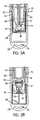
- FIG. 4is a longitudinal cross-sectional view of the container of FIG. 1 , illustrating an unused automatic injector within the container;
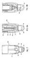
- FIG. 5Ais a longitudinal cross-sectional view of a portion of the container similar to the view of FIG. 4 , illustrating the administration end of the automatic injector within the container prior to use;
- FIG. 5Bis a longitudinal cross-sectional view similar to that of FIG. 5A , illustrating the administration end of the automatic injector after the automatic injector has been used and returned to the container;
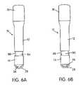
- FIG. 6Ais a perspective view of the exterior of the container with the automatic injector in the position illustrated in FIG. 5A ;
- FIG. 6Bis a perspective view of the exterior of the container with the automatic injector in the used position illustrated in FIG. 5B , showing a used injector indicator flag visible from the exterior of the container;
- FIG. 7is a side elevational view of a portion of the exterior of a container according to another embodiment of the present invention.
- FIG. 8Ais a longitudinal cross-sectional view of a portion of the container of FIG. 7 , illustrating an unused automatic injector within the container;
- FIG. 8Bis a longitudinal cross-sectional view similar to that of FIG. 8A , illustrating the administration end of the automatic injector after the automatic injector has been used and returned to the container;
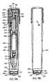
- FIG. 9Ais a longitudinal cross-sectional view of a container according to another embodiment of the invention with an automatic injector installed therein;
- FIG. 9Bis a longitudinal cross-sectional view of the container of FIG. 9A without the automatic injector;
- FIGS. 10A and 10Bare side elevational views of the container with an automatic injector installed therein before and after use, respectively;
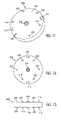
- FIG. 11is a perspective view of a needle retainer that is installed within the container of FIGS. 9A and 9B ;
- FIG. 12is a top plan view of the needle retainer of FIG. 11 ;
- FIG. 13is a side elevational view of the needle retainer of FIG. 11 ;
- FIG. 14is an isolated perspective view of a shield that is installed within the container of FIGS. 9A and 9B ;
- FIG. 15is a sectional perspective view of the shield of FIG. 14 ;
- FIG. 16is a sectional side elevational view of a portion of the container of FIGS. 9A and 9B with an automatic injector installed therein after use of the automatic injector, illustrating the needle of the automatic injector in a crippled position;
- FIG. 17is a side elevational view of the exterior of the container of FIGS. 9A and 9B ;
- FIG. 18is a perspective view of an S-clip that may be used to attach two containers according to the invention.
- FIG. 19is a top plan view of the S-clip of FIG. 18 ;
- FIG. 20is a side elevational view of the S-clip of FIG. 18 .
- FIG. 1is a perspective view of a container, generally indicated at 10 , according to one embodiment of the invention.
- the container 10is generally cylindrical and is sized to contain an automatic injector (not shown in FIG. 1 ).
- the container 10may be used with any type or variety of automatic injector known in the art.
- the container 10would be distributed with an automatic injector inside, and would thus serve, at least in part, as product packaging for the automatic injector. Accordingly, the central exterior surface 12 of the container 10 provides space for product labeling, usage directions, or other necessary indicia. Such labeling and indicia may be printed on labels and attached to the exterior surface 12 , or they may be formed or printed on the central exterior surface 12 during the manufacture of the container 10 .
- the container 10may be made of a conventional plastic material such as polypropylene (PP).
- PPpolypropylene
- the container 10 , or portions thereof,may also be made of more penetration resistant materials, such as poly(ethylene terephthalate) (PET), as will be explained below in more detail.
- PETpoly(ethylene terephthalate)
- the container 10has a closed needle-receiving end, generally indicated at 14 , and an open end 16 opposite the needle-receiving end 14 .
- the opening 24 in the open end 20is of sufficient size to allow an automatic injector to be removed and replaced.
- FIG. 1the open end 16 is covered by a removable cap 18 .
- FIG. 2is a side elevational view of the container 10 with the cap 18 removed.
- FIG. 3is a perspective view of the cap 18 in isolation.
- the open end 16 of the container 10includes threads 20 that engage corresponding threads 22 on the interior of the cap 18 to releasably engage the cap 18 and container 10 .
- Two sets of six individual non-contiguous helical threads 20are provided on container 10 , and the cap includes a corresponding set of conventional contiguous threads 22 .
- This arrangementallows the cap 18 to start threading onto the container 10 when placed on the container 10 in a number of initial positions, and thus making it easier to thread the cap 18 on the container 10 .
- a conventional set of threadsmay be used on the cap 18 and container 10 .
- the exterior surface of the cap 18may also be provided with a number of contoured portions spaced around its circumference in order to provide the user with a better grip when opening or closing the cap 18 .
- the container 10is designed to house an automatic injector such that its needle-bearing end extends toward the needle-receiving end 14 of the container 10 .
- the needle-receiving end 14 of the container 10may have a smaller diameter than the rest of the container 10 , depending on the diameter of the automatic injector that it is designed to accommodate, so as to encourage users to insert the automatic injector in the proper orientation.
- the container 10 of the illustrated embodimenthas a gradual taper, from more narrow toward the needle-receiving end 14 to broader near the cap 18 . That taper corresponds to the contours of one type of automatic injector; many other contours are possible.
- the container 10is designed to house an automatic injector with the needle-bearing end of the automatic injector facing the needle-receiving end 14 of the container 10
- the automatic injectormay be placed in the container, accidentally or deliberately, such that the needle-bearing end of the automatic injector faces the cap 18 .
- the cap 18is preferably made of a material of sufficient thickness, durability, and penetration resistance such that if the automatic injector were to be accidentally activated with the needle-bearing end facing the cap 18 , the protruding needle would not penetrate the cap 18 .
- one wall of the cap 18such as the top wall, indicated by reference numeral 19 in FIG. 4 , may be particularly thickened or may be provided with a “pad” of penetration resistant material, either plastic or metal, secured to an inward surface thereof.
- the material of which the needle-receiving end 14 is madeis at least partially translucent and, in some embodiments, may be fully transparent. In other embodiments, the needle-receiving end 14 may be translucent, partially translucent, or opaque, with particular portions that are fully or partially transparent.
- the entire container 10may also be made of a translucent or transparent material. This feature and its utility will be described in more detail below.
- the container 10 and cap 18may be capable of blocking or absorbing ultraviolet (UV) light.
- UV-absorbing agentcould be added to the polymer mix from which the container 10 is formed. Many such UV-absorbing agents are known in the polymer and molding arts. UV blocking or absorbing capability helps to ensure that the medicament within the automatic injector is not compromised by exposure to UV light, even if the container 10 is significantly light permeable.
- the bottom 26 of the needle-receiving end 14has a shock-absorbing eyelet 28 .
- the eyelet 28takes the form of an arc of material that extends across the bottom 26 of the needle-receiving end 14 .
- the eyelet 28acts as a shock absorber to absorb at least some of the force if the container 10 is dropped and the bottom 26 of the needle-receiving end 14 impacts another surface.
- the eyelet 28would also allow a user to attach a carrying strap, so that the container may be conveniently carried.
- the eyelet 28may provide from about 1 mm to about 5 mm of clearance for the attachment of a strap. In other embodiments of the invention, there may be significant clearance between the eyelet 28 and the bottom 26 .
- the eyelet 28covers approximately one-third of the bottom 26 of the needle-receiving end 14 . In other embodiments, the eyelet 28 may cover from about 10% to substantially the entirety of the bottom 26 of the needle-receiving end 14 . If the eyelet 28 covers only a small portion of the bottom 26 of the needle-receiving end 14 , it may provide less effective shock absorption if the container 10 impacts off-center.
- the eyelet 28may have a thickness of from about 0.5 mm to about 2 mm, which may vary along its arc.
- FIG. 4is a longitudinal cross-sectional view of the container 10 showing an automatic injector 50 installed therein.
- the automatic injector 50 illustrated in FIG. 4has a single chamber and is designed to contain and inject a single component liquid medicament composition.
- the container 10may also be used with two component wet/wet mixing automatic injectors, as well as two component wet/dry mixing automatic injectors, and any other type of automatic injector known in the art.
- the automatic injector 50is shown schematically in FIG. 4 and certain features have been omitted for clarity of illustration, because the workings of the automatic injector 50 are not critical to the functioning of this embodiment of the container 10 . Full details of operation for automatic injectors such as automatic injector 50 may be found in commonly assigned U.S. Pat. Nos. 5,391,151 and 6,210,369, the contents of which are incorporated by reference herein.
- the automatic injector 50has an outer housing 52 and a cartridge 54 disposed within the outer housing 52 .
- the cartridge 54includes a medicament storage compartment 56 , an attached needle assembly 58 , and a plunger 60 at the top of the medicament storage compartment 56 .
- the cartridge 54may include one or two compartments, so as to accommodate medications having a wet component and a dry component (so-called “wet/dry automatic injectors”) or a wet component and another wet component (so-called “wet/wet automatic injectors”).
- wet/dry automatic injectorsa wet component and a dry component
- wet/wet automatic injectorsa wet component and another wet component
- Descriptions of several suitable types of wet/dry automatic injectorscan be found in commonly-assigned U.S. Pat. Nos. 6,641,561 and 6,770,052. The entire contents of those applications are incorporated by reference herein in their entirety.
- the automatic injector 50also includes an actuation assembly, only portions of which are shown in FIG. 4 .
- a stored energy source(not shown in FIG. 4 ), such as a compressed spring, would be carried in the space above the plunger 60 .
- a safety cap 62prevents the stored energy source from releasing and activating the device.
- the precise manner of activation of the automatic injector 50is not critical to the container 10 ; however, in a typical automatic injector 50 , the safety cap 62 would be removed and the needle end 64 of the automatic injector 50 would be pressed against an administration site (e.g., the user's thigh), causing a relative movement of upper 66 and lower 68 portions of the housing 52 that causes the stored energy source to deploy and activate the automatic injector 50 .
- an administration sitee.g., the user's thigh
- the upper portion 66 of the housing 52includes an inwardly extending shoulder 70 against which the lower portion 68 of the housing bears.
- the stored energy sourcepropels the needle 72 through its protective sleeve 74 and the bottom 76 of the housing 52 and subsequently causes the plunger 60 to move downward, causing the medicament compound in the cartridge 54 to be dispensed through the needle 72 .
- internal spring force exerted against the needle 72prevents the needle 72 from being retracted back into the housing 52 once it has been used.
- FIG. 4illustrates the position of the automatic injector 50 within the container 10 prior to use.
- the automatic injector 50is completely within the container 10 and the container 10 is slightly longer than the automatic injector 50 . Therefore, when the user removes the cap 18 , he or she will have to tip the container 10 to remove the automatic injector 50 from it. This is advantageous because if the automatic injector 50 did protrude from the container 10 , the user might try to remove it from the container 10 by tugging on or near the safety cap 62 , which might cause the safety cap 62 to come loose and could ultimately result in the premature or unintended activation of the automatic injector 50 .
- the difference in length between the container 10 and the automatic injector 50is most desirably the smallest length difference between the two that will prevent the user from accidentally removing the safety cap 62 . That difference may be no more than a few millimeters.
- the container 10should be as small as possible, so that it can be conveniently and consistently carried by a user. If the container 10 is too large, the user may not be inclined to carry it, in which case the automatic injector 50 may not be available when it is needed.
- FIG. 5Ais a longitudinal cross-sectional view of a portion of the automatic injector 50 , showing its “administration end” within the container 10 .
- the interior of the container 10has a small inwardly extending circumferential shoulder or shelf 78 formed at the top of the needle-receiving end 14 of the container 10 .
- An indicator sleeve 80has an outwardly extending lip 82 that rests on the shelf 78 .
- the indicator sleeve 80is formed of a brightly colored material that can be penetrated by the needle 72 (e.g. red plastic).
- the indicator sleeve 80is covered by a cover sleeve 84 , which surrounds and covers the indicator sleeve 80 .
- the indicator sleeve 80includes a prong or series of prongs 86 that are engaged by corresponding clips 87 on the end of the cover sleeve 84 to retain the cover sleeve 84 in the position illustrated in FIG. 5A . To some extent, the indicator sleeve 80 and cover sleeve 84 also cushion the automatic injector 50 against shock and impact.
- the automatic injector 50When the user needs to use the automatic injector 50 , he or she removes the cap 18 from the container 10 , removes the automatic injector 50 from the container 10 as was described above, and then uses the automatic injector 50 in accordance with the manufacturer's instructions. Once the automatic injector 50 is used, the user replaces the automatic injector 50 in the container 10 , inserting the automatic injector 50 such that the needle 72 is oriented toward the needle-receiving end 14 of the container 10 . If the automatic injector 50 is difficult to re-insert, the user may place the cap 18 on the container 10 and turn the cap 18 toward engagement with the container 10 .
- the torque applied to the cap 18will cause an axial force to be exerted on the automatic injector 50 , forcing it into the container 10 .
- the cap 18may thus provide the user with a significant mechanical advantage if used to “seat” the used automatic injector 50 within the container 10 in this manner.
- the motion of the needle 72causes a series of movements, which may result in the position shown in FIG. 5B .
- the needle 72As the needle 72 is moved into the container, it penetrates the bottom of the indicator sleeve 80 , disengages the cover sleeve 84 from the indicator sleeve 80 , and drives the cover sleeve 84 downward, toward the bottom of the container 10 .
- FIGS. 6A and 6Bare perspective views of the container 10 before and after the used automatic injector 50 has been replaced in the container 10 , respectively.
- the indicator sleeve 80is clearly visible through a translucent window 88 in the needle-receiving portion 14
- FIG. 6Aonly the uncolored cover sleeve 84 is visible in the translucent window 88 .
- the needle 72 of the automatic injectormay range in length from about 0.4 inches (approximately 10 millimeters) to 0.975 inches (approximately 24.8 millimeters). If the needle 72 is sufficiently long, the automatic injector 50 will not be fully seated in the container 10 when the needle 72 strikes the bottom of the container 10 . In that case, as the user pushes the automatic injector 50 fully into the container 10 , the needle 72 bends and becomes crippled, as shown in FIG. 5B .
- the bottom 26 of the container 10 and the cover sleeve 84may be used to cripple the needle, it is advantageous if those components are made of or lined with a tough material that resists penetration, such as PET.
- a reinforcing plate of either plastic or metalcould be fixed to the cover sleeve 84 or the inside bottom 26 of the container 10 .
- Embodiments of the invention that employ a reinforcing component at the bottom of the containerwill be described below in more detail.
- the penetrated indicator sleeve 80acts as a retaining member and exerts a frictional force on the needle 72 that opposes an attempt to remove the automatic injector 50 from the container 10 .
- the indicator sleeve 80or its bottom portion 81 , may be made of a thermoplastic elastomer having a relatively high coefficient of friction so as to produce the greatest possible amount of friction when in engagement with the needle 72 .
- the needle 72is of a length that causes it to be crippled by striking the bottom 26 of the container 10 , the crippled needle 72 itself may make the used automatic injector 50 difficult to remove from the container 10 .
- a cover sleeve 84is moved by the needle 72 of the automatic injector 50
- a green indicator flagcould be shown through the window 88 until the used automatic injector 50 is inserted into the container 10 , at which time the needle 72 of the automatic injector 50 would cause the green indicator flag to be moved to reveal a white or red “used” indicator flag.
- Thiscould be implemented, for example, by making the cover sleeve 84 green and the underlying indicator sleeve 80 either white or red.
- a green indicator flag or sleevecould be covered by another movable sleeve.
- the indicating mechanism and its colorsshould be chosen so as to give the user a readily identifiable indication of use.
- FIG. 7is an elevational view of the needle-receiving end 114 of a container 100 according to another embodiment of the invention.
- the needle-receiving end 114is sufficiently transparent to allow the needle 72 of the automatic injector 50 to be seen from the outside of the container 100 . Therefore, the needle 72 itself acts as an indicator that the automatic injector 50 has been used.
- the container 100has pointing indicia 115 inscribed on the outer surface of the needle-receiving end 114 to direct the user's attention to the portion of the needle-receiving end 114 where the needle 72 is visible when the automatic injector 50 has been used.
- the pointing indicia 115may be painted, marked, integrally formed, or applied as labels to the needle-receiving end 114 . If desired, the pointing indicia 115 may also be omitted.
- FIGS. 8A and 8Bare longitudinal cross-sectional views of the portion of the container 100 shown in FIG. 7 .
- the interior mechanismis simpler than in the container 10 of the previous embodiment.
- FIG. 8Aillustrates the position of the automatic injector 50 in the container 100 before activation.
- the bottom of the automatic injector 50rests on a needle retainer 180 , which is a flexible, resilient component, typically made of a thermoplastic elastomer, that cushions the automatic injector 50 before use.
- the needle 72penetrates and advances through the needle retainer 180 .
- the needle 72can then be seen through a transparent window 188 in the needle-receiving portion 114 , indicating that the automatic injector has been used.
- the needle retainer 180exerts a frictional force on the needle 72 that tends to oppose an attempt to remove it. If the needle 72 is long enough, it may strike the bottom 182 of the needle-receiving portion 114 and become crippled, as shown in FIG. 8B .
- the crippled needle 72may also make the used automatic injector 50 difficult to remove from the container 100 .
- the bottom 182 of the container 100would be made of a penetration resistant material, or reinforced with such a material, so as to facilitate needle crippling.
- containers according to the inventionmay combine the features of the two embodiments described above to provide a colored, highly visible “used” indicator in combination with a simplified container that is designed to retain a used automatic injector.
- the indicator functionmay be provided as a portion of the automatic injector itself.
- FIGS. 9A and 9Bare longitudinal cross-sectional views of a container, generally indicated at 200 , according to another embodiment of the invention.
- FIG. 9Ashows the container 200 with an exemplary automatic injector 202 , also in longitudinal cross-section;
- FIG. 9Bshows the container 200 in longitudinal cross-section without the automatic injector 202 .
- the container 200includes many of the features of the containers 10 and 100 that were described above. Certain features that are not shown in FIGS. 9A and 9B , such as an eyelet 28 , may also be included in the container 200 .
- the automatic injector 202has an actuation assembly, generally indicated at 250 , a chamber, generally indicated at 252 , that is made of glass, plastic, or another suitable material and is configured to contain a medicament solution, and a hub and needle assembly, generally indicated at 254 .
- the automatic injector 202may be of the type designed to carry a two component wet/dry medicament or a two component wet/wet medicament, in which case it would have two chambers separated by an appropriate sealing structure.
- U.S. Pat. Nos. 6,641,561 and 6,770,052provide details on the construction of such automatic injectors and their sealing and mixing structures.
- the actuation assembly 250includes a safety cap 256 mounted on the rear end of the automatic injector 202 .
- the safety cap 256includes a downwardly extending safety pin 258 formed on the inward side of the top surface of the cap 256 .
- the safety pin 258extends between and engages spring fingers 260 formed in the split rearward portion of a collet 262 .
- the spring fingers 260each have semi-conical end surfaces 264 that are constructed and arranged to engage corresponding semi-conical surfaces 266 arrayed around an aperture 268 in the rear of the inner housing portion 270 of the automatic injector 202 .
- the engagement of the safety pin 258 with the spring fingers 260keeps them spread apart and prevents them from deflecting inwardly to enter the aperture 268 .
- the collet 262is surrounded by a cylindrical sleeve having an inwardly extending flange at the rearward end thereof.
- the collet 262has a forward annular flange 272 .
- a coil spring 274surrounds the collet 262 and is compressed between the flange of the cylindrical sleeve and the annular flange 272 .
- the collet 262engages a spacer-indicator member 276 .
- the spacer-indicator member 276is a brightly colored component, typically made of red plastic or the equivalent, that includes one end configured to receive and engage the collet 262 and the other end configured to receive and engage a plunger 278 positioned sealingly within the chamber 252 for sliding movement therein. (Alternatively, the spacer-indicator member 276 may engage an insert connected to the plunger 278 .)
- the spacer-indicator member 276is generally cylindrical in shape, and may be varied in overall length so as to allow the plunger 278 to be initially positioned within the chamber 252 at any desired position.
- the spacer-indicator member 276may be made with a longer length, so that plunger 278 is initially positioned further along the length of the chamber 252 and the effective volume of the chamber 252 is thus reduced. Therefore, when the volume of the medicament dose is smaller than the volume of the chamber 252 , a spacer-indicator member 276 of an appropriate length can reduce the possibility that an air bubble will accumulate in the unused volume of the chamber 252 .
- the safety cap 256is manually removed from the automatic injector 202 , thus the safety pin 258 is removed from its initial position separating the spring fingers 264 .
- the spring fingers 264are forced upward and, by interaction with the semi-conical surfaces 266 , toward one another and off of the retaining surfaces of the flange.
- the compressed spring 274is then free to release its stored energy to move the collet 262 forwardly under the force of the spring 274 , causing the needle 72 to extend through the forward portion of the housing 280 and the medicament to be injected.
- FIGS. 10A and 10Bare side elevational views of a container 200 with an automatic injector 202 installed therein before and after use of the automatic injector 202 , respectively.
- the container 200 and automatic injector 202are both preferably made of a material that is at least partially translucent and, more preferably, a material that is at least partially transparent, such as a transparent or substantially transparent plastic.
- a transparent or substantially transparent plasticAs shown in FIGS. 10A and 10B , the container 200 and automatic injector 202 are both preferably made of a material that is at least partially translucent and, more preferably, a material that is at least partially transparent, such as a transparent or substantially transparent plastic.
- labels 282 containing identifying information, patient instructions, and other necessary indiciaare placed over portions of the automatic injector 202 , leaving a transparent window 284 at a position adjacent to the position into which the spacer-indicator member 276 moves after use of the automatic injector 202 .
- the transparent window 284is empty and clear.
- the spacer-indicator 276has moved into the transparent window 284 , giving the user a highly visible indication that the automatic injector 202 has been used.
- portions of the housing of the automatic injector 202could be made of an opaque plastic and the transparent window 284 could be made of a transparent plastic.
- the spacer-indicator 276is generally not configured to be centered in the transparent window 284 once the automatic injector 202 has been used. Rather, as shown in FIG. 10B , it is typically designed to be positioned slightly below center, which provides more visibility at tolerance extremes.
- the container 200has a mechanism for retaining the needle 72 of the automatic injector 202 similar to that of the container 100 illustrated in FIGS. 7 , 8 A, and 8 B.
- the needle-receiving end 204 of the container 200has an inner circumferential shelf 206 . Resting on the inner circumferential shelf 206 is a needle retainer 208 .
- the needle retainer 208is slightly larger in diameter than the diameter of the container 200 itself, such that the needle retainer 208 engages the inner walls of the container 200 with an interference fit. Other arrangements are possible; in certain embodiments, the needle retainer 208 may be fused in place, secured with adhesives, snapped in place, or welded in place.
- the needle retainer 208is formed of a resilient material and, because of its thickness and resilience, acts as a shock absorber, cushioning the automatic injector 202 before use.
- the cushioning effect of the needle retainer 208reduces or eliminates the need for an external structure such as an eyelet 28 .
- FIGS. 11 , 12 , and 13are perspective, top plan, and side elevational views, respectively, of the needle retainer 208 .
- the needle retainer 208is substantially circular.
- the needle retainer 208includes two vent slots 211 spaced 180° from each other along the circumference of the needle retainer 208 .
- the vent slots 211ensure that pressure does not build up on one side of the needle retainer 208 and enable any gases or vapors to move out of the container 200 .
- the container 200also has a vent hole 210 , which is shown in FIG. 9B .
- In the center of the upper surface of the needle retainer 208is a raised central portion 214 .
- a similar raised central portion 216is provided on the bottom surface, as shown in FIG. 13 .
- the raised central portions 214 , 216provide the needle retainer 208 with a greater effective thickness in the area through which the needle 72 will be inserted, thereby improving the frictional “grip” of the needle retainer 208 on the needle 72 and also aid gating of the tool during the manufacturing process.
- the needle retainer 208also includes a number of protuberances 219 spaced regularly around its circumference. The protuberances 219 improve the manufacturability of the container 200 and its assembly process by making it easier to separate stacked needle retainers 208 during manufacturing and assembly. However, needle retainers 208 may be made without the raised central portions 214 , 216 and the protuberances 219 .
- a shield 212which is held in place both by engagement with the inner circumferential shelf 206 and by the fit of the needle retainer 208 above it.
- the shield 212is substantially cap-shaped and rests on the bottom of the needle-receiving end 204 of the container with its open end facing upwards.
- the shield 212is intended to prevent the needle 72 from penetrating the container 200 .
- the shield 212would be made of stainless steel or another metal that is compatible with (i.e., not corroded or otherwise damaged by) the medicament in the automatic injector 202 .
- the shield 212may be made of PET or another penetration resistant plastic.
- FIG. 14is a perspective view of the shield 212 in isolation
- FIG. 15is a sectional perspective view of the shield 212 in isolation.
- in the center of the shield 212is an upwardly extending conical portion 220 .
- the conical portion 220increases the possibility that a shorter needle will be crippled after insertion into the container 200 .
- the upwardly extending conical portion 220also reduces the amount of force necessary to deflect and cripple the needle 72 .
- the shield 212need not include a conical projection 220 per se; an upward projection of the shield 212 , if provided, could have substantially any shape.
- the needle 72is of sufficient length to strike the shield 212 and become crippled, its final position after contact with the shield 212 may be that shown in FIG. 16 , a sectional side elevational view of a portion of the needle-receiving end 204 of the container 200 .
- the shield 212in addition to the conical portion 220 , the shield 212 also includes an upwardly extending flange 222 that helps to prevent any portion of the crippled, deformed needle 72 from escaping the area enclosed by the shield 212 and the needle retainer 208 .
- the spacing between the needle retainer 208 and the shield 212adds to the cushioning and shock absorbing effect of the needle retainer 208 , because the needle retainer 208 can deflect and rebound to dissipate shock.
- the container 200includes a central upward projection 224 that extends upwardly from the bottom of the container 200 and coincides in position with the conical portion 220 of the shield 212 .
- the projection 224may be used to center the shield 212 when the shield is inserted into the container 200 , and it may also reinforce the conical portion 220 , particularly if the conical portion 220 deflects downwardly in response to initial contact with the needle 72 .
- the projection 224is not provided.
- FIG. 17is a side elevational view of the exterior of the container 200 .
- the exterior of the container 200also includes certain advantageous features.
- a frosted grip area 300increases the tactility of the surface and encourages a firm grip.
- a smooth recessed surface 302provides a location for a clip or other such retaining device to be attached around the circumference of the container 200 .
- the recessed surface 302is also preferably transparent and may be used as a window so that users and treating medical professionals can determine whether the automatic injector 202 is in the container 200 and, if so, what drug it contains.
- labels on the automatic injector 202 describing its medicamentwould be placed so as to coincide with the position of the recessed surface 302 . Because the surface 302 is recessed, it is less likely to become scratched and obscure the interior of the container 200 . Additionally, labels on the automatic injector 202 may be visible through portions of the container 200 other than the frosted grip area 300 .
- a flange 304 on the upper portion of the container 200defines the position to which the user will need to screw the cap 18 in order to ensure that the needle 72 is crippled after it enters the container 200 .
- the arrangement of the container 200 and the cap 18is such that a small vent gap is left between the two when the cap 18 is screwed down fully.
- the container 200also includes two anti-roll protrusions 306 spaced opposite one another on the lower portion of the outer surface of the container 200 .
- the anti-roll protrusions 306reduce the likelihood that the container 200 will roll more than about 180° from the position in which it is placed.
- the container 200does not include an eyelet 28 , its bottom surface 308 is rounded, which helps to dissipate shock if the container 200 is dropped on its end.
- the recessed surface 302provides a surface over which a clip may be placed to attach multiple containers 200 to one another. Such clips may be used on other containers 10 , 100 according to the invention, although the recessed surface 302 substantially prevents a clip from sliding along the length of the container 200 .
- FIG. 18is a perspective view of an S-clip, generally indicated at 308 , that may be used with containers 10 , 100 , 200 according to the invention.
- FIGS. 19 and 20are, respectively, a top plan view and a side elevational view of the clip 308 .
- the clip 308is contoured such that it has two clip openings 310 , with each clip opening 310 configured to accept one container 10 , 200 , 300 .
- the two clip openings 310are opposite one another, and the portions of the clip 308 that define each opening 310 are joined by a central web of material 311 .
- the clip 308may be formed from any suitable material that permits the clip to 308 to flex and engage the side of the container 10 , 200 , 300 .
- the engaging surfaces 312 that define the interior of each of the clip openings 310have a different radius of curvature than that of the containers 10 , 200 , 300 .
- the different radius of curvature of the engaging surfaces 312 and the containers 10 , 200 , 300allows the clip 308 to engage a container with minimal contact between the engaging surfaces 312 and the container 10 , 100 , 200 .
- Minimal contact between the engaging surfaces 312 and the container 200reduces the likelihood that the engaging surfaces 312 of the clip 308 will scratch the transparent recessed surface 302 of the container 200 .
- the overall “S” shape of the clip 308will reduce the amount of force needed to remove a container 10 , 100 , 200 from the clip 308 in an emergency, as compared with a more conventional double C-clip. Additionally, texture 314 on the outer surface of the clip 308 makes the clip 308 easier to grip and may encourage users to replace the container 10 , 100 , 200 in the clip 308 once the automatic injector 50 , 202 has been used. It is contemplated that the clip 308 may include a suitable attachment assembly for carrying the clip on a belt or securing to an article of clothing or desired surface or article.
Landscapes
- Health & Medical Sciences (AREA)
- Animal Behavior & Ethology (AREA)
- Public Health (AREA)
- Anesthesiology (AREA)
- Biomedical Technology (AREA)
- Heart & Thoracic Surgery (AREA)
- Hematology (AREA)
- Life Sciences & Earth Sciences (AREA)
- Vascular Medicine (AREA)
- Engineering & Computer Science (AREA)
- Veterinary Medicine (AREA)
- General Health & Medical Sciences (AREA)
- Diabetes (AREA)
- Infusion, Injection, And Reservoir Apparatuses (AREA)
- Catching Or Destruction (AREA)
- Details Of Rigid Or Semi-Rigid Containers (AREA)
- Packages (AREA)
- Packaging Of Annular Or Rod-Shaped Articles, Wearing Apparel, Cassettes, Or The Like (AREA)
Abstract
Description
Claims (50)
Priority Applications (1)
| Application Number | Priority Date | Filing Date | Title |
|---|---|---|---|
| US10/978,827US7635348B2 (en) | 2003-11-04 | 2004-11-02 | Container for medicament automatic injector and automatic injector adapted therefor |
Applications Claiming Priority (3)
| Application Number | Priority Date | Filing Date | Title |
|---|---|---|---|
| US51673303P | 2003-11-04 | 2003-11-04 | |
| US51791003P | 2003-11-07 | 2003-11-07 | |
| US10/978,827US7635348B2 (en) | 2003-11-04 | 2004-11-02 | Container for medicament automatic injector and automatic injector adapted therefor |
Publications (2)
| Publication Number | Publication Date |
|---|---|
| US20050148933A1 US20050148933A1 (en) | 2005-07-07 |
| US7635348B2true US7635348B2 (en) | 2009-12-22 |
Family
ID=34594848
Family Applications (1)
| Application Number | Title | Priority Date | Filing Date |
|---|---|---|---|
| US10/978,827Expired - Fee RelatedUS7635348B2 (en) | 2003-11-04 | 2004-11-02 | Container for medicament automatic injector and automatic injector adapted therefor |
Country Status (12)
| Country | Link |
|---|---|
| US (1) | US7635348B2 (en) |
| EP (1) | EP1684828B1 (en) |
| JP (1) | JP4881741B2 (en) |
| AT (1) | ATE460193T1 (en) |
| AU (1) | AU2004289228B2 (en) |
| CA (1) | CA2544520A1 (en) |
| DE (1) | DE602004025964D1 (en) |
| DK (1) | DK1684828T3 (en) |
| ES (1) | ES2342399T3 (en) |
| IL (1) | IL175429A (en) |
| TW (1) | TW200518799A (en) |
| WO (1) | WO2005046765A2 (en) |
Cited By (45)
| Publication number | Priority date | Publication date | Assignee | Title |
|---|---|---|---|---|
| US20060096877A1 (en)* | 2004-11-09 | 2006-05-11 | Kaveh Khajavi | System and method for preventing wrong-site surgeries |
| US20080015511A1 (en)* | 2004-09-02 | 2008-01-17 | Sanovi-Aventis Deutschland Gmbh | Method Of Assembly Of Drug Delivery Devices |
| US20080154200A1 (en)* | 2005-01-24 | 2008-06-26 | Lesch Paul R | Prefilled syringe jet injector |
| US20090292246A1 (en)* | 2008-05-20 | 2009-11-26 | Slate John B | Cassette for a hidden injection needle |
| US20100022955A1 (en)* | 2008-07-23 | 2010-01-28 | Slate John B | System and method for an injection using a syringe needle |
| US20100238038A1 (en)* | 2004-12-31 | 2010-09-23 | Tecpharma Licensing Ag. | Service life timer for a device for administering a product in doses |
| US8627816B2 (en) | 2011-02-28 | 2014-01-14 | Intelliject, Inc. | Medicament delivery device for administration of opioid antagonists including formulations for naloxone |
| US8915889B2 (en) | 2008-08-05 | 2014-12-23 | Antares Pharma, Inc. | Multiple dosage injector |
| US20150025472A1 (en)* | 2013-03-12 | 2015-01-22 | Robert Dax Colwell | Cover for a syringe and method of making |
| US8939943B2 (en) | 2011-01-26 | 2015-01-27 | Kaleo, Inc. | Medicament delivery device for administration of opioid antagonists including formulations for naloxone |
| US8945063B2 (en) | 2009-03-20 | 2015-02-03 | Antares Pharma, Inc. | Hazardous agent injection system |
| US9022980B2 (en) | 2005-02-01 | 2015-05-05 | Kaleo, Inc. | Medical injector simulation device |
| US9144648B2 (en) | 2006-05-03 | 2015-09-29 | Antares Pharma, Inc. | Injector with adjustable dosing |
| US9168107B2 (en) | 2004-11-09 | 2015-10-27 | Startbox, Llc | System and method for preventing wrong-site surgeries |
| US9220660B2 (en) | 2011-07-15 | 2015-12-29 | Antares Pharma, Inc. | Liquid-transfer adapter beveled spike |
| US9333309B2 (en) | 2002-02-11 | 2016-05-10 | Antares Pharma, Inc. | Intradermal injector |
| US9364611B2 (en) | 2012-05-07 | 2016-06-14 | Antares Pharma, Inc. | Needle assisted jet injection device having reduced trigger force |
| US9393367B2 (en) | 2013-03-12 | 2016-07-19 | Antares Pharma, Inc. | Prefilled syringes and kits thereof |
| US9415176B1 (en) | 2015-01-22 | 2016-08-16 | West Pharmaceutical Services, Inc. | Autoinjector having an end-of-dose visual indicator |
| US9446195B2 (en) | 2011-07-15 | 2016-09-20 | Antares Pharma, Inc. | Injection device with cammed ram assembly |
| US9486583B2 (en) | 2012-03-06 | 2016-11-08 | Antares Pharma, Inc. | Prefilled syringe with breakaway force feature |
| US9542826B2 (en) | 2012-12-27 | 2017-01-10 | Kaleo, Inc. | Devices, systems and methods for locating and interacting with medicament delivery systems |
| US9707354B2 (en) | 2013-03-11 | 2017-07-18 | Antares Pharma, Inc. | Multiple dosage injector with rack and pinion dosage system |
| US9721064B2 (en) | 2004-11-09 | 2017-08-01 | Startbox, Llc | System and method for preventing wrong-site surgeries |
| US9744302B2 (en) | 2013-02-11 | 2017-08-29 | Antares Pharma, Inc. | Needle assisted jet injection device having reduced trigger force |
| US9808582B2 (en) | 2006-05-03 | 2017-11-07 | Antares Pharma, Inc. | Two-stage reconstituting injector |
| US9867949B2 (en) | 2008-03-10 | 2018-01-16 | Antares Pharma, Inc. | Injector safety device |
| US9950125B2 (en) | 2012-04-06 | 2018-04-24 | Antares Pharma, Inc. | Needle assisted jet injection administration of testosterone compositions |
| US9974904B2 (en) | 2008-05-20 | 2018-05-22 | Avant Medical Corp. | Autoinjector system |
| USD829890S1 (en) | 2012-04-20 | 2018-10-02 | Amgen Inc. | Injection device |
| US10092706B2 (en) | 2011-04-20 | 2018-10-09 | Amgen Inc. | Autoinjector apparatus |
| US10092703B2 (en) | 2013-03-15 | 2018-10-09 | Amgen Inc. | Drug cassette, autoinjector, and autoinjector system |
| US10492990B2 (en) | 2013-03-15 | 2019-12-03 | Amgen Inc. | Drug cassette, autoinjector, and autoinjector system |
| US10646654B2 (en) | 2014-03-28 | 2020-05-12 | Sanofi-Aventis Deutschland Gmbh | Autoinjector triggered by skin contact |
| USD892311S1 (en) | 2017-10-25 | 2020-08-04 | Sanofi-Aventis Deutschland Gmbh | Injection device |
| USD898908S1 (en) | 2012-04-20 | 2020-10-13 | Amgen Inc. | Pharmaceutical product cassette for an injection device |
| USD903856S1 (en) | 2018-06-29 | 2020-12-01 | Regeneron Pharmaceuticals, Inc. | Auto-injector |
| US20200397992A1 (en)* | 2011-09-23 | 2020-12-24 | Sanofi-Aventis Deutschland Gmbh | Medicament Delivery Device and Actuation Mechanism for a Drug Delivery Device |
| US10937537B2 (en) | 2017-01-17 | 2021-03-02 | Kaleo, Inc. | Medicament delivery devices with wireless connectivity and event detection |
| USD932006S1 (en) | 2018-11-21 | 2021-09-28 | Regeneron Pharmaceuticals, Inc. | Auto-injector cap |
| US11400206B2 (en)* | 2015-07-10 | 2022-08-02 | Fresenius Kabi Deutschland Gmbh | Syringe packaging system |
| US11484654B2 (en) | 2017-06-30 | 2022-11-01 | Regeneron Pharmaceuticals, Inc. | Auto-injector with anti-roll features |
| US11541188B2 (en) | 2013-07-09 | 2023-01-03 | Sanofi-Aventis Deutschland Gmbh | Autoinjector |
| US11929160B2 (en) | 2018-07-16 | 2024-03-12 | Kaleo, Inc. | Medicament delivery devices with wireless connectivity and compliance detection |
| US12097357B2 (en) | 2008-09-15 | 2024-09-24 | West Pharma. Services IL, Ltd. | Stabilized pen injector |
Families Citing this family (67)
| Publication number | Priority date | Publication date | Assignee | Title |
|---|---|---|---|---|
| FR2852851B1 (en)* | 2003-03-25 | 2006-01-06 | Sedat | NEEDLE PROTECTION DEVICE FOR SYRINGE, AND INJECTION DEVICE COMPRISING SYRINGE AND PROTECTIVE DEVICE |
| FR2861310B1 (en)* | 2003-10-22 | 2006-09-22 | Plastef Investissements | SECURE INJECTION SYRINGE DEVICE |
| GB0414054D0 (en) | 2004-06-23 | 2004-07-28 | Owen Mumford Ltd | Improvements relating to automatic injection devices |
| US8048035B2 (en)* | 2004-08-06 | 2011-11-01 | Meridian Medical Technologies, Inc. | Automatic injector with needle cover |
| GB0418389D0 (en)* | 2004-08-18 | 2004-09-22 | Liversidge Barry P | Injection apparatus |
| US7905352B2 (en)* | 2004-12-06 | 2011-03-15 | Washington Biotech Corporation | Kits containing medicine injection devices and containers |
| WO2007008257A2 (en)* | 2005-07-06 | 2007-01-18 | Washington Biotech Corp. | Method and apparatus for delivering epinephrine |
| US20110226646A1 (en)* | 2004-12-06 | 2011-09-22 | Wyrick Ronald E | Kits Containing Medicine Injection Devices And Containers |
| US7297136B2 (en)* | 2004-12-06 | 2007-11-20 | Wyrick Ronald E | Medicine injection devices and methods |
| GB0601309D0 (en) | 2006-01-23 | 2006-03-01 | Medical House The Plc | Injection device |
| US20070173770A1 (en) | 2006-01-23 | 2007-07-26 | The Medical House Plc | Injection device |
| TW200744568A (en)* | 2006-02-28 | 2007-12-16 | Verus Pharmaceuticals Inc | Epinephrine dosing regimens |
| GB2437922B (en) | 2006-05-10 | 2010-12-08 | Owen Mumford Ltd | Injection device comprising a window and a shutter element |
| TW200817049A (en)* | 2006-06-05 | 2008-04-16 | Verus Pharmaceuticals Inc | Epinephrine dosing regimens comprising buccal, lingual or sublingual and injectable dosage forms |
| KR101396797B1 (en) | 2006-06-30 | 2014-05-26 | 애브비 바이오테크놀로지 리미티드 | Automatic injection device |
| GB0625169D0 (en) | 2006-12-18 | 2007-01-24 | Medical House Plc The | Improved autoinjector |
| CA2683949A1 (en)* | 2007-04-18 | 2008-10-30 | Meridian Medical Technologies, Inc. | Container for an automatic injector |
| FR2922457B1 (en)* | 2007-10-23 | 2010-10-29 | Plastef Investissements | SYRINGE DEVICE WITH PROTECTIVE CAP. |
| FR2922455B1 (en)* | 2007-10-23 | 2010-10-29 | Plastef Investissements | SYRINGE DEVICE COMPRISING A SYRINGE BODY AND A SUPPORT SLEEVE. |
| WO2009092430A1 (en)* | 2008-01-24 | 2009-07-30 | Arzneimittel Gmbh Apotheker Vetter & Co. Ravensburg | Syringe system and method for the production thereof |
| WO2010081838A2 (en)* | 2009-01-14 | 2010-07-22 | Novartis Ag | Sterile prefilled container |
| GB0901801D0 (en)* | 2009-02-05 | 2009-03-11 | Medical House Plc The | Improved autoinjector |
| US8764706B2 (en) | 2009-02-06 | 2014-07-01 | Becton, Dickinson And Company | Disposable pen needle with re-use prevention features |
| US8366682B2 (en) | 2009-03-04 | 2013-02-05 | Washington Biotech Corporation | Medicine injection apparatuses |
| GB2469672B (en) | 2009-04-23 | 2013-09-25 | Medical House Ltd | Improved autoinjector |
| WO2010127146A1 (en) | 2009-04-29 | 2010-11-04 | Abbott Biotechnology Ltd | Automatic injection device |
| US10350364B2 (en) | 2009-11-11 | 2019-07-16 | Windgap Medical, Inc. | Portable Drug Mixing and Delivery Device and Associated Methods |
| EP2512558A4 (en) | 2009-12-15 | 2014-08-13 | Abbvie Biotechnology Ltd | IMPROVED TRIP PUSHER FOR AUTOMATIC INJECTION DEVICE |
| NZ702172A (en) | 2010-04-21 | 2016-03-31 | Abbvie Biotechnology Ltd | Wearable automatic injection device for controlled delivery of therapeutic agents |
| AU2015203703B2 (en)* | 2010-05-20 | 2018-01-18 | Becton, Dickinson And Company | Drug delivery device |
| BR112012029642B1 (en) | 2010-05-20 | 2020-05-26 | Becton, Dickinson And Company | DRUG ADMINISTRATION DEVICE |
| ES2710905T3 (en) | 2011-01-24 | 2019-04-29 | E3D Agricultural Coop Association Ltd | Injector |
| BR112013018905B1 (en) | 2011-01-24 | 2021-07-13 | Abbvie Biotechnology Ltd | AUTOMATIC INJECTION DEVICES THAT HAVE OVERMOLDED HANDLE SURFACES. |
| KR101989342B1 (en) | 2011-01-24 | 2019-06-14 | 애브비 바이오테크놀로지 리미티드 | Removal of needle shields from syringes and automatic injection devices |
| US9022990B2 (en) | 2011-04-04 | 2015-05-05 | Tech Group Europe Limited | Needle safety shield |
| EP2476450A1 (en)* | 2011-08-29 | 2012-07-18 | Novo Nordisk A/S | A pen needle container and a method for bending a needle cannula |
| RU2620351C2 (en)* | 2011-09-22 | 2017-05-24 | Эббви Инк. | Automated injector |
| CA2849806A1 (en)* | 2011-09-22 | 2013-03-28 | Abbvie Inc. | Automatic injection device |
| JP6298056B2 (en)* | 2012-08-20 | 2018-03-20 | サノフィ−アベンティス・ドイチュラント・ゲゼルシャフト・ミット・ベシュレンクテル・ハフツング | Cap for drug delivery device and drug delivery device |
| US9050416B2 (en) | 2012-11-01 | 2015-06-09 | Tech Group Europe Limited | Needle Safety device with floating ring |
| US10391262B2 (en) | 2014-03-18 | 2019-08-27 | Windgap Medical, Inc. | Removable actuating cap for use with an auto-injector assembly |
| US10569017B2 (en) | 2013-03-15 | 2020-02-25 | Windgap Medical, Inc. | Portable drug mixing and delivery device and associated methods |
| US9907910B2 (en) | 2013-03-15 | 2018-03-06 | Windgap Medical, Inc. | Portable drug mixing and delivery device and associated methods |
| JP6560187B2 (en) | 2013-03-15 | 2019-08-14 | ウインドギャップ メディカル インコーポレイテッド | Portable drug mixing and delivery system and method |
| US11116903B2 (en) | 2014-08-18 | 2021-09-14 | Windgap Medical, Inc | Compression seal for use with a liquid component storage vial of an auto-injector |
| CA2994803C (en) | 2014-08-18 | 2023-09-12 | Windgap Medical, Inc. | Portable drug mixing and delivery device and associated methods |
| WO2016058009A2 (en)* | 2014-10-06 | 2016-04-14 | Aktivax | Auto-injector |
| CA2994300C (en) | 2015-08-13 | 2023-12-05 | Windgap Medical, Inc. | Mixing and injection device with sterility features |
| USD818587S1 (en) | 2016-03-29 | 2018-05-22 | Abbevie Inc. | Automatic injection device |
| USD819198S1 (en) | 2016-04-28 | 2018-05-29 | Amgen Inc. | Autoinjector with removable cap |
| EP3381491A1 (en) | 2017-03-28 | 2018-10-03 | Tecpharma Licensing AG | Pen cap for an injection device comprising a needle destroyer |
| WO2019086411A2 (en) | 2017-11-02 | 2019-05-09 | Sanofi | Button and button assembly for a drug delivery device |
| CN111511657B (en)* | 2017-12-21 | 2022-04-29 | 英杰特药业瑞典有限公司 | Auto-injector kit for reducing oxygen in packaging |
| US20200140175A1 (en)* | 2018-11-02 | 2020-05-07 | Entegris, Inc. | Multi piece fitment for a fluid container |
| GB201912135D0 (en)* | 2019-08-23 | 2019-10-09 | Msc Tech Limited | Improvements to medical device |
| USD1010811S1 (en) | 2019-09-30 | 2024-01-09 | Amgen Inc. | Handheld drug delivery device |
| USD1030040S1 (en) | 2020-01-14 | 2024-06-04 | Amgen Inc. | Handheld drug delivery device |
| USD1030041S1 (en) | 2020-01-14 | 2024-06-04 | Amgen Inc. | Handheld drug delivery device |
| US20230051213A1 (en)* | 2020-02-06 | 2023-02-16 | Eli Lilly And Company | Drug container systems including lock-out mechanisms |
| USD974547S1 (en) | 2020-11-05 | 2023-01-03 | Amgen Inc. | Handheld drug delivery device |
| USD973866S1 (en) | 2020-11-05 | 2022-12-27 | Amgen Inc. | Handheld drug delivery device |
| USD962423S1 (en) | 2020-11-05 | 2022-08-30 | Amgen Inc. | Handheld drug delivery device |
| USD985116S1 (en) | 2021-03-10 | 2023-05-02 | Amgen Inc. | Handheld drug delivery device |
| USD985117S1 (en) | 2021-03-10 | 2023-05-02 | Amgen Inc. | Handheld drug delivery device |
| WO2022192308A1 (en)* | 2021-03-10 | 2022-09-15 | Amgen Inc. | Drug delivery device having removable cap |
| USD985118S1 (en) | 2021-03-10 | 2023-05-02 | Amgen Inc. | Handheld drug delivery device |
| USD985119S1 (en) | 2021-03-30 | 2023-05-02 | Amgen Inc. | Handheld drug delivery device |
Citations (64)
| Publication number | Priority date | Publication date | Assignee | Title |
|---|---|---|---|---|
| US1506429A (en) | 1921-03-21 | 1924-08-26 | Kahn Alfred | Pocket medical case |
| US1711594A (en)* | 1927-04-28 | 1929-05-07 | Holden T Gillespie | Syringe container |
| US1718701A (en) | 1929-04-05 | 1929-06-25 | O'sullivan David Lee | Vest-pocket hypodermic-syringe container |
| US1838825A (en) | 1929-01-31 | 1931-12-29 | Aaron A Goldstein | Sterilizing case |
| US2400722A (en) | 1944-07-10 | 1946-05-21 | Harry L Swan | Hypodermic needle case |
| US3363497A (en)* | 1966-09-21 | 1968-01-16 | Grossman Music Corp | Recorder |
| US3367486A (en) | 1966-11-16 | 1968-02-06 | Pharmaseal Lab | Hypodermic syringe package |
| US4188950A (en) | 1978-10-30 | 1980-02-19 | Wardlaw Stephen C | Disposable syringe |
| US4332323A (en) | 1977-10-26 | 1982-06-01 | Konsivenior Ab | Destruction device for injection needles |
| US4634428A (en) | 1985-08-15 | 1987-01-06 | Cuu Cwo Liang | Cover for a disposable syringe |
| US4716710A (en) | 1985-07-01 | 1988-01-05 | Institut-Merieux | Process for the preparation in a series of self-injectable syringes in a sealed container, for lyophilized medications, and device for the implementation of said process |
| US4728320A (en) | 1987-04-17 | 1988-03-01 | Chen Chang Cheng | Syringe cap with hammer |
| US4728321A (en) | 1987-04-16 | 1988-03-01 | Ming-Chiu Wu | Syringe cap with adhesive holding plug |
| US4735311A (en) | 1986-04-09 | 1988-04-05 | The West Company | Needle shield assembly |
| US4872552A (en) | 1988-11-16 | 1989-10-10 | Mid-South Products Engineering, Inc. | Safety packaging for hypodermic syringes with needles and the like |
| US4877132A (en) | 1989-03-20 | 1989-10-31 | Luke Makris | Syringe protection device |
| US5002533A (en) | 1989-09-05 | 1991-03-26 | Jullien Robert G | Syringe guard apparatus |
| US5015234A (en) | 1989-06-02 | 1991-05-14 | Jullien Robert G | Syringe guard apparatus |
| US5074848A (en) | 1988-06-02 | 1991-12-24 | Burt Wayne R | Needle receptacle |
| US5080651A (en) | 1989-06-02 | 1992-01-14 | Jullien Robert G | Combined protective guard and destruction system for a syringe |
| US5084027A (en) | 1991-07-19 | 1992-01-28 | Bernard Daniel H | Needle cover with safety disposal chamber |
| US5104375A (en) | 1989-10-16 | 1992-04-14 | Johnson & Johnson Medical, Inc. | Locking holder for a pair of syringes and method of use |
| US5137516A (en) | 1989-11-28 | 1992-08-11 | Glaxo Group Limited | Triggered application device for medicament to be more descriptive of the invention |
| US5156267A (en) | 1991-06-14 | 1992-10-20 | Dynamic Bio-Apparatuses, Inc. | Syringe inhibiting container |
| US5161681A (en) | 1989-04-24 | 1992-11-10 | Kemp David R | Safety container for hypodermic syringes |
| US5172808A (en) | 1988-07-01 | 1992-12-22 | John Bruno | Device for safely transporting one or more hypodermic needles or the like from point of use to point of ultimate disposal |
| US5188600A (en) | 1989-06-02 | 1993-02-23 | Jullien Robert G | Syringe guard apparatus |
| US5232454A (en) | 1990-08-01 | 1993-08-03 | Smiths Industries Medical Systems, Inc. | Safety needle container |
| US5232455A (en) | 1991-01-07 | 1993-08-03 | Smiths Industries Medical Systems, Inc. | Syringe with protective housing |
| US5358489A (en)* | 1993-05-27 | 1994-10-25 | Washington Biotech Corporation | Reloadable automatic or manual emergency injection system |
| EP0634140A1 (en) | 1992-09-26 | 1995-01-18 | Juridical Foundation The Chemo-Sero-Therapeutic Research Institute | Applicator for tissue adhesive |
| US5391151A (en)* | 1991-01-15 | 1995-02-21 | Survival Technology, Inc. | Subcutaneous injector |
| US5417326A (en) | 1994-03-31 | 1995-05-23 | Winer; Donald B. | Syringe container |
| US5519931A (en) | 1994-03-16 | 1996-05-28 | Syncor International Corporation | Container and method for transporting a syringe containing radioactive material |
| US5522503A (en) | 1994-12-20 | 1996-06-04 | Halbich; Frank | Syringe case |
| US5566828A (en) | 1995-02-21 | 1996-10-22 | The Upjohn Company | Locking package for a syringe |
| US5695472A (en) | 1993-05-27 | 1997-12-09 | Washington Biotech Corporation | Modular automatic or manual emergency medicine injection system |
| WO1998055168A1 (en) | 1997-06-04 | 1998-12-10 | Eli Lilly And Company | Medication delivery apparatus |
| US5918443A (en) | 1995-04-05 | 1999-07-06 | Phillips; Paul B. | Medical syringe containment |
| WO1999037343A1 (en) | 1998-01-24 | 1999-07-29 | Medico Development Investment Company | Injection device |
| US5941854A (en)* | 1994-12-19 | 1999-08-24 | Bhitiyakul; Somsak | Intravenous catheter |
| US5950827A (en) | 1998-10-08 | 1999-09-14 | Odom; Jeffrey L. | Injector pen storage case |
| US5980495A (en) | 1997-04-23 | 1999-11-09 | Claas Kgaa | Needle cap device for a pre-fillable one-time injection apparatus |
| US6001082A (en)* | 1998-02-20 | 1999-12-14 | Becton Dickinson And Company | Medication delivery pen with an integral magnifying pocket clip |
| US6026959A (en) | 1996-07-22 | 2000-02-22 | Protec Medical Corporation | Protective kit for medical sharps and method for using same |
| DE19959507A1 (en) | 1998-12-17 | 2000-06-21 | Medico Dev Investment Co | Injection device comprises a cocking unit that moves the injection liquid container and brings spring into cocked state only then injection needle is in place |
| US6102893A (en) | 1995-05-24 | 2000-08-15 | Biodome | Prefilled safety syringe |
| US6155420A (en) | 1995-04-05 | 2000-12-05 | Phillips; Paul B. | Medical syringe container |
| US6183439B1 (en) | 1998-03-20 | 2001-02-06 | Medikit Co., Ltd | Device for winding and storing a used needle of an injector |
| US6210369B1 (en)* | 1997-12-16 | 2001-04-03 | Meridian Medical Technologies Inc. | Automatic injector |
| US6217558B1 (en)* | 1998-12-17 | 2001-04-17 | Filiberto P. Zadini | Apparatus for blood vessel type differentiation for syringes and guidewires placement devices |
| US6241709B1 (en) | 1994-05-30 | 2001-06-05 | B D Medico S.A.R.L. | Injection device |
| WO2001078806A1 (en) | 2000-04-18 | 2001-10-25 | Baske Pty Ltd. | Syringe retaining device and spoon for injectables |
| US20010054631A1 (en) | 1998-10-20 | 2001-12-27 | Martha Giannou | Protective case for carrying a fragile object |
| US20020049407A1 (en) | 2000-10-10 | 2002-04-25 | Hill Robert L. | Wet/dry automatic injector assembly |
| US20020050462A1 (en) | 2000-05-12 | 2002-05-02 | Melinda Penney | Cases for medication delivery devices |
| US6576918B1 (en) | 2000-08-09 | 2003-06-10 | Syncor International Corp. | Container and method for transporting a syringe containing radioactive material |
| US20030132128A1 (en) | 2002-01-11 | 2003-07-17 | Mazur David P. | Container for syringe |
| US6641561B1 (en) | 2000-10-10 | 2003-11-04 | Meridian Medical Technologies, Inc. | Drug delivery device |
| US6702785B1 (en) | 2000-05-04 | 2004-03-09 | Collins Sonya Dene | Needle capper |
| US20040069667A1 (en) | 2000-05-12 | 2004-04-15 | Tomellini Dalita R. | Cases for medication delivery devices |
| US6767336B1 (en)* | 2003-01-09 | 2004-07-27 | Sheldon Kaplan | Automatic injector |
| US6793646B1 (en)* | 1999-04-16 | 2004-09-21 | Becton Dickinson And Company | Pen style injector with automated substance combining feature |
| US20040236289A1 (en)* | 2001-03-15 | 2004-11-25 | Ferguson F. Mark | Safety shield for medical needles |
Family Cites Families (4)
| Publication number | Priority date | Publication date | Assignee | Title |
|---|---|---|---|---|
| US50462A (en)* | 1865-10-17 | Improved sewed shoe | ||
| US69667A (en)* | 1867-10-08 | Improvement in horse-bakes | ||
| JPS63264075A (en)* | 1987-04-22 | 1988-10-31 | 陳 昌政 | Injection needle treatment cap for disposable syringe |
| US6482733B2 (en)* | 2000-05-15 | 2002-11-19 | Asm Microchemistry Oy | Protective layers prior to alternating layer deposition |
- 2004
- 2004-11-02USUS10/978,827patent/US7635348B2/ennot_activeExpired - Fee Related
- 2004-11-03ATAT04800616Tpatent/ATE460193T1/ennot_activeIP Right Cessation
- 2004-11-03AUAU2004289228Apatent/AU2004289228B2/ennot_activeCeased
- 2004-11-03ESES04800616Tpatent/ES2342399T3/ennot_activeExpired - Lifetime
- 2004-11-03DEDE602004025964Tpatent/DE602004025964D1/ennot_activeExpired - Lifetime
- 2004-11-03JPJP2006538443Apatent/JP4881741B2/ennot_activeExpired - Fee Related
- 2004-11-03WOPCT/US2004/036497patent/WO2005046765A2/enactiveApplication Filing
- 2004-11-03DKDK04800616.7Tpatent/DK1684828T3/enactive
- 2004-11-03EPEP04800616Apatent/EP1684828B1/ennot_activeExpired - Lifetime
- 2004-11-03CACA002544520Apatent/CA2544520A1/ennot_activeAbandoned
- 2004-11-03TWTW093133463Apatent/TW200518799A/enunknown
- 2006
- 2006-05-04ILIL175429Apatent/IL175429A/ennot_activeIP Right Cessation
Patent Citations (68)
| Publication number | Priority date | Publication date | Assignee | Title |
|---|---|---|---|---|
| US1506429A (en) | 1921-03-21 | 1924-08-26 | Kahn Alfred | Pocket medical case |
| US1711594A (en)* | 1927-04-28 | 1929-05-07 | Holden T Gillespie | Syringe container |
| US1838825A (en) | 1929-01-31 | 1931-12-29 | Aaron A Goldstein | Sterilizing case |
| US1718701A (en) | 1929-04-05 | 1929-06-25 | O'sullivan David Lee | Vest-pocket hypodermic-syringe container |
| US2400722A (en) | 1944-07-10 | 1946-05-21 | Harry L Swan | Hypodermic needle case |
| US3363497A (en)* | 1966-09-21 | 1968-01-16 | Grossman Music Corp | Recorder |
| US3367486A (en) | 1966-11-16 | 1968-02-06 | Pharmaseal Lab | Hypodermic syringe package |
| US4332323A (en) | 1977-10-26 | 1982-06-01 | Konsivenior Ab | Destruction device for injection needles |
| US4188950A (en) | 1978-10-30 | 1980-02-19 | Wardlaw Stephen C | Disposable syringe |
| US4716710A (en) | 1985-07-01 | 1988-01-05 | Institut-Merieux | Process for the preparation in a series of self-injectable syringes in a sealed container, for lyophilized medications, and device for the implementation of said process |
| US4634428A (en) | 1985-08-15 | 1987-01-06 | Cuu Cwo Liang | Cover for a disposable syringe |
| US4735311A (en) | 1986-04-09 | 1988-04-05 | The West Company | Needle shield assembly |
| US4728321A (en) | 1987-04-16 | 1988-03-01 | Ming-Chiu Wu | Syringe cap with adhesive holding plug |
| US4728320A (en) | 1987-04-17 | 1988-03-01 | Chen Chang Cheng | Syringe cap with hammer |
| US5074848A (en) | 1988-06-02 | 1991-12-24 | Burt Wayne R | Needle receptacle |
| US5172808A (en) | 1988-07-01 | 1992-12-22 | John Bruno | Device for safely transporting one or more hypodermic needles or the like from point of use to point of ultimate disposal |
| US4872552A (en) | 1988-11-16 | 1989-10-10 | Mid-South Products Engineering, Inc. | Safety packaging for hypodermic syringes with needles and the like |
| US4877132A (en) | 1989-03-20 | 1989-10-31 | Luke Makris | Syringe protection device |
| US5161681A (en) | 1989-04-24 | 1992-11-10 | Kemp David R | Safety container for hypodermic syringes |
| US5080651A (en) | 1989-06-02 | 1992-01-14 | Jullien Robert G | Combined protective guard and destruction system for a syringe |
| US5015234A (en) | 1989-06-02 | 1991-05-14 | Jullien Robert G | Syringe guard apparatus |
| US5188600A (en) | 1989-06-02 | 1993-02-23 | Jullien Robert G | Syringe guard apparatus |
| US5002533A (en) | 1989-09-05 | 1991-03-26 | Jullien Robert G | Syringe guard apparatus |
| US5104375A (en) | 1989-10-16 | 1992-04-14 | Johnson & Johnson Medical, Inc. | Locking holder for a pair of syringes and method of use |
| US5137516A (en) | 1989-11-28 | 1992-08-11 | Glaxo Group Limited | Triggered application device for medicament to be more descriptive of the invention |
| US5232454A (en) | 1990-08-01 | 1993-08-03 | Smiths Industries Medical Systems, Inc. | Safety needle container |
| US5232455A (en) | 1991-01-07 | 1993-08-03 | Smiths Industries Medical Systems, Inc. | Syringe with protective housing |
| US5391151A (en)* | 1991-01-15 | 1995-02-21 | Survival Technology, Inc. | Subcutaneous injector |
| US5156267A (en) | 1991-06-14 | 1992-10-20 | Dynamic Bio-Apparatuses, Inc. | Syringe inhibiting container |
| US5084027A (en) | 1991-07-19 | 1992-01-28 | Bernard Daniel H | Needle cover with safety disposal chamber |
| EP0634140A1 (en) | 1992-09-26 | 1995-01-18 | Juridical Foundation The Chemo-Sero-Therapeutic Research Institute | Applicator for tissue adhesive |
| US5358489A (en)* | 1993-05-27 | 1994-10-25 | Washington Biotech Corporation | Reloadable automatic or manual emergency injection system |
| US5695472A (en) | 1993-05-27 | 1997-12-09 | Washington Biotech Corporation | Modular automatic or manual emergency medicine injection system |
| US5519931A (en) | 1994-03-16 | 1996-05-28 | Syncor International Corporation | Container and method for transporting a syringe containing radioactive material |
| US5417326A (en) | 1994-03-31 | 1995-05-23 | Winer; Donald B. | Syringe container |
| US6241709B1 (en) | 1994-05-30 | 2001-06-05 | B D Medico S.A.R.L. | Injection device |
| US5941854A (en)* | 1994-12-19 | 1999-08-24 | Bhitiyakul; Somsak | Intravenous catheter |
| US5522503A (en) | 1994-12-20 | 1996-06-04 | Halbich; Frank | Syringe case |
| US5566828A (en) | 1995-02-21 | 1996-10-22 | The Upjohn Company | Locking package for a syringe |
| US5918443A (en) | 1995-04-05 | 1999-07-06 | Phillips; Paul B. | Medical syringe containment |
| US6155420A (en) | 1995-04-05 | 2000-12-05 | Phillips; Paul B. | Medical syringe container |
| US6102893A (en) | 1995-05-24 | 2000-08-15 | Biodome | Prefilled safety syringe |
| US6026959A (en) | 1996-07-22 | 2000-02-22 | Protec Medical Corporation | Protective kit for medical sharps and method for using same |
| US5980495A (en) | 1997-04-23 | 1999-11-09 | Claas Kgaa | Needle cap device for a pre-fillable one-time injection apparatus |
| WO1998055168A1 (en) | 1997-06-04 | 1998-12-10 | Eli Lilly And Company | Medication delivery apparatus |
| US6454746B1 (en)* | 1997-06-04 | 2002-09-24 | Eli Lilly And Company | Medication delivery apparatus |
| US6210369B1 (en)* | 1997-12-16 | 2001-04-03 | Meridian Medical Technologies Inc. | Automatic injector |
| WO1999037343A1 (en) | 1998-01-24 | 1999-07-29 | Medico Development Investment Company | Injection device |
| US6001082A (en)* | 1998-02-20 | 1999-12-14 | Becton Dickinson And Company | Medication delivery pen with an integral magnifying pocket clip |
| US6183439B1 (en) | 1998-03-20 | 2001-02-06 | Medikit Co., Ltd | Device for winding and storing a used needle of an injector |
| US5950827A (en) | 1998-10-08 | 1999-09-14 | Odom; Jeffrey L. | Injector pen storage case |
| US20010054631A1 (en) | 1998-10-20 | 2001-12-27 | Martha Giannou | Protective case for carrying a fragile object |
| US6405912B2 (en) | 1998-10-20 | 2002-06-18 | Zoni Inc. | Protective case for carrying a fragile object |
| US6217558B1 (en)* | 1998-12-17 | 2001-04-17 | Filiberto P. Zadini | Apparatus for blood vessel type differentiation for syringes and guidewires placement devices |
| DE19959507A1 (en) | 1998-12-17 | 2000-06-21 | Medico Dev Investment Co | Injection device comprises a cocking unit that moves the injection liquid container and brings spring into cocked state only then injection needle is in place |
| US6641560B1 (en)* | 1998-12-17 | 2003-11-04 | B. D. Medico S.A.R.L. | Injecting device |
| US6793646B1 (en)* | 1999-04-16 | 2004-09-21 | Becton Dickinson And Company | Pen style injector with automated substance combining feature |
| WO2001078806A1 (en) | 2000-04-18 | 2001-10-25 | Baske Pty Ltd. | Syringe retaining device and spoon for injectables |
| US6702785B1 (en) | 2000-05-04 | 2004-03-09 | Collins Sonya Dene | Needle capper |
| US6595362B2 (en) | 2000-05-12 | 2003-07-22 | Lindon Products Inc. | Cases for medication delivery devices |
| US20020050462A1 (en) | 2000-05-12 | 2002-05-02 | Melinda Penney | Cases for medication delivery devices |
| US20040069667A1 (en) | 2000-05-12 | 2004-04-15 | Tomellini Dalita R. | Cases for medication delivery devices |
| US6576918B1 (en) | 2000-08-09 | 2003-06-10 | Syncor International Corp. | Container and method for transporting a syringe containing radioactive material |
| US6641561B1 (en) | 2000-10-10 | 2003-11-04 | Meridian Medical Technologies, Inc. | Drug delivery device |
| US20020049407A1 (en) | 2000-10-10 | 2002-04-25 | Hill Robert L. | Wet/dry automatic injector assembly |
| US20040236289A1 (en)* | 2001-03-15 | 2004-11-25 | Ferguson F. Mark | Safety shield for medical needles |
| US20030132128A1 (en) | 2002-01-11 | 2003-07-17 | Mazur David P. | Container for syringe |
| US6767336B1 (en)* | 2003-01-09 | 2004-07-27 | Sheldon Kaplan | Automatic injector |
Cited By (130)
| Publication number | Priority date | Publication date | Assignee | Title |
|---|---|---|---|---|
| US9333309B2 (en) | 2002-02-11 | 2016-05-10 | Antares Pharma, Inc. | Intradermal injector |
| US9737670B2 (en) | 2002-02-11 | 2017-08-22 | Antares Pharma, Inc. | Intradermal injector |
| US20080015511A1 (en)* | 2004-09-02 | 2008-01-17 | Sanovi-Aventis Deutschland Gmbh | Method Of Assembly Of Drug Delivery Devices |
| US8961472B2 (en)* | 2004-09-02 | 2015-02-24 | Sanofi-Aventis Deutschland Gmbh | Method of assembly of drug delivery devices |
| US9168107B2 (en) | 2004-11-09 | 2015-10-27 | Startbox, Llc | System and method for preventing wrong-site surgeries |
| US20060096877A1 (en)* | 2004-11-09 | 2006-05-11 | Kaveh Khajavi | System and method for preventing wrong-site surgeries |
| US8616215B2 (en)* | 2004-11-09 | 2013-12-31 | Startbox, Llc | System and method for preventing wrong-site surgeries |
| US9721064B2 (en) | 2004-11-09 | 2017-08-01 | Startbox, Llc | System and method for preventing wrong-site surgeries |
| US20100238038A1 (en)* | 2004-12-31 | 2010-09-23 | Tecpharma Licensing Ag. | Service life timer for a device for administering a product in doses |
| US8556847B2 (en)* | 2004-12-31 | 2013-10-15 | Tecpharma Licensing Ag | Service life timer for a device for administering a product in doses |
| US8562564B2 (en) | 2005-01-24 | 2013-10-22 | Antares Pharma, Inc. | Prefilled syringe jet injector |
| US8021335B2 (en)* | 2005-01-24 | 2011-09-20 | Antares Pharma, Inc. | Prefilled syringe jet injector |
| US9629959B2 (en) | 2005-01-24 | 2017-04-25 | Antares Pharma, Inc. | Prefilled syringe jet injector |
| US10478560B2 (en) | 2005-01-24 | 2019-11-19 | Antares Pharma, Inc. | Prefilled syringe injector |
| US11446441B2 (en) | 2005-01-24 | 2022-09-20 | Antares Pharma, Inc. | Prefilled syringe injector |
| US20080154200A1 (en)* | 2005-01-24 | 2008-06-26 | Lesch Paul R | Prefilled syringe jet injector |
| US9180259B2 (en) | 2005-01-24 | 2015-11-10 | Antares Pharma, Inc. | Prefilled syringe jet injector |
| US10796604B2 (en) | 2005-02-01 | 2020-10-06 | Kaleo, Inc. | Medical injector simulation device and containers for storing delivery devices |
| US9805620B2 (en) | 2005-02-01 | 2017-10-31 | Kaleo, Inc. | Medical injector simulation device |
| US9022980B2 (en) | 2005-02-01 | 2015-05-05 | Kaleo, Inc. | Medical injector simulation device |
| US9144648B2 (en) | 2006-05-03 | 2015-09-29 | Antares Pharma, Inc. | Injector with adjustable dosing |
| US10688250B2 (en) | 2006-05-03 | 2020-06-23 | Antares Pharma, Inc. | Two-stage reconstituting injector |
| US11547808B2 (en) | 2006-05-03 | 2023-01-10 | Antares Pharma, Inc. | Two-stage reconstituting injector |
| US11471600B2 (en) | 2006-05-03 | 2022-10-18 | Antares Pharma, Inc. | Injector with adjustable dosing |
| US9808582B2 (en) | 2006-05-03 | 2017-11-07 | Antares Pharma, Inc. | Two-stage reconstituting injector |
| US10543316B2 (en) | 2006-05-03 | 2020-01-28 | Antares Pharma, Inc. | Injector with adjustable dosing |
| US12121704B2 (en) | 2006-05-03 | 2024-10-22 | Antares Pharma, Inc. | Injector with adjustable dosing |
| US11684723B2 (en) | 2008-03-10 | 2023-06-27 | Antares Pharma, Inc. | Injector safety device |
| US9867949B2 (en) | 2008-03-10 | 2018-01-16 | Antares Pharma, Inc. | Injector safety device |
| US10709844B2 (en) | 2008-03-10 | 2020-07-14 | Antares Pharma, Inc. | Injector safety device |
| US8177749B2 (en) | 2008-05-20 | 2012-05-15 | Avant Medical Corp. | Cassette for a hidden injection needle |
| US11883633B2 (en) | 2008-05-20 | 2024-01-30 | Avant Medical Corp. | Autoinjector system |
| US10792426B2 (en) | 2008-05-20 | 2020-10-06 | Avant Medical Corp. | Autoinjector system |
| US10864324B2 (en) | 2008-05-20 | 2020-12-15 | Avant Medical Corp. | Autoinjector system |
| US9974904B2 (en) | 2008-05-20 | 2018-05-22 | Avant Medical Corp. | Autoinjector system |
| US20090292246A1 (en)* | 2008-05-20 | 2009-11-26 | Slate John B | Cassette for a hidden injection needle |
| US9925336B2 (en) | 2008-05-20 | 2018-03-27 | Avant Medical Corp. | Cassette for a hidden injection needle |
| US10639422B2 (en) | 2008-07-23 | 2020-05-05 | Avant Medical Corp. | System and method for an injection using a syringe needle |
| US9616173B2 (en) | 2008-07-23 | 2017-04-11 | Avant Medical Corporation | System and method for an injection using a syringe needle |
| US12186535B2 (en) | 2008-07-23 | 2025-01-07 | Avant Medical Corp. | System and method for an injection using a syringe needle |
| US8052645B2 (en) | 2008-07-23 | 2011-11-08 | Avant Medical Corp. | System and method for an injection using a syringe needle |
| US20100022955A1 (en)* | 2008-07-23 | 2010-01-28 | Slate John B | System and method for an injection using a syringe needle |
| US11724032B2 (en) | 2008-07-23 | 2023-08-15 | Avant Medical Corp. | System and method for an injection using a syringe needle |
| US9561333B2 (en) | 2008-08-05 | 2017-02-07 | Antares Pharma, Inc. | Multiple dosage injector |
| US8915889B2 (en) | 2008-08-05 | 2014-12-23 | Antares Pharma, Inc. | Multiple dosage injector |
| US11058824B2 (en) | 2008-08-05 | 2021-07-13 | Antares Pharma, Inc. | Multiple dosage injector |
| US10300212B2 (en) | 2008-08-05 | 2019-05-28 | Antares Pharma, Inc. | Multiple dosage injector |
| US12097357B2 (en) | 2008-09-15 | 2024-09-24 | West Pharma. Services IL, Ltd. | Stabilized pen injector |
| US11497753B2 (en) | 2009-03-20 | 2022-11-15 | Antares Pharma, Inc. | Hazardous agent injection system |
| US9750881B2 (en) | 2009-03-20 | 2017-09-05 | Antares Pharma, Inc. | Hazardous agent injection system |
| US8945063B2 (en) | 2009-03-20 | 2015-02-03 | Antares Pharma, Inc. | Hazardous agent injection system |
| US12357642B2 (en) | 2009-03-20 | 2025-07-15 | Antares Pharma, Inc. | Hazardous agent injection system |
| US10555954B2 (en) | 2009-03-20 | 2020-02-11 | Antares Pharma, Inc. | Hazardous agent injection system |
| US8939943B2 (en) | 2011-01-26 | 2015-01-27 | Kaleo, Inc. | Medicament delivery device for administration of opioid antagonists including formulations for naloxone |
| US9022022B2 (en) | 2011-02-28 | 2015-05-05 | Kaleo, Inc. | Medicament delivery device for administration of opioid antagonists including formulations for naloxone |
| US8627816B2 (en) | 2011-02-28 | 2014-01-14 | Intelliject, Inc. | Medicament delivery device for administration of opioid antagonists including formulations for naloxone |
| US12350480B2 (en) | 2011-04-20 | 2025-07-08 | Amgen Inc. | Autoinjector apparatus |
| US10918805B2 (en) | 2011-04-20 | 2021-02-16 | Amgen Inc. | Autoinjector apparatus |
| US11986643B2 (en) | 2011-04-20 | 2024-05-21 | Amgen Inc. | Autoinjector apparatus |
| US11419990B2 (en) | 2011-04-20 | 2022-08-23 | Amgen Inc. | Autoinjector apparatus |
| US10092706B2 (en) | 2011-04-20 | 2018-10-09 | Amgen Inc. | Autoinjector apparatus |
| US12179007B2 (en) | 2011-07-15 | 2024-12-31 | Antares Pharma, Inc. | Injection device with cammed ram assembly |
| US10279131B2 (en) | 2011-07-15 | 2019-05-07 | Antares Pharma, Inc. | Injection device with cammed RAM assembly |
| US10568809B2 (en) | 2011-07-15 | 2020-02-25 | Ferring B.V. | Liquid-transfer adapter beveled spike |
| US11185642B2 (en) | 2011-07-15 | 2021-11-30 | Antares Pharma, Inc. | Injection device with cammed ram assembly |
| US9220660B2 (en) | 2011-07-15 | 2015-12-29 | Antares Pharma, Inc. | Liquid-transfer adapter beveled spike |
| US9446195B2 (en) | 2011-07-15 | 2016-09-20 | Antares Pharma, Inc. | Injection device with cammed ram assembly |
| US12403258B2 (en) | 2011-09-23 | 2025-09-02 | Sanofi-Aventis Deutschland Gmbh | Medicament delivery device and actuation mechanism for a drug delivery device |
| US12403259B2 (en) | 2011-09-23 | 2025-09-02 | Sanofi-Aventis Deutschland Gmbh | Medicament delivery device and actuation mechanism for a drug delivery device |
| US20200397992A1 (en)* | 2011-09-23 | 2020-12-24 | Sanofi-Aventis Deutschland Gmbh | Medicament Delivery Device and Actuation Mechanism for a Drug Delivery Device |
| US11918786B2 (en)* | 2011-09-23 | 2024-03-05 | Sanofi-Aventis Deutschland Gmbh | Medicament delivery device and actuation mechanism for a drug delivery device |
| US11602597B2 (en) | 2012-03-06 | 2023-03-14 | Antares Pharma, Inc. | Prefilled syringe with breakaway force feature |
| US9486583B2 (en) | 2012-03-06 | 2016-11-08 | Antares Pharma, Inc. | Prefilled syringe with breakaway force feature |
| US12409272B2 (en) | 2012-03-06 | 2025-09-09 | Antares Pharma, Inc. | Prefilled syringe with breakaway force feature |
| US10478559B2 (en) | 2012-03-06 | 2019-11-19 | Antares Pharma, Inc. | Prefilled syringe with breakaway force feature |
| US11771646B2 (en) | 2012-04-06 | 2023-10-03 | Antares Pharma, Inc. | Needle assisted jet injection administration of testosterone compositions |
| US9950125B2 (en) | 2012-04-06 | 2018-04-24 | Antares Pharma, Inc. | Needle assisted jet injection administration of testosterone compositions |
| US10821072B2 (en) | 2012-04-06 | 2020-11-03 | Antares Pharma, Inc. | Needle assisted jet injection administration of testosterone compositions |
| USD898908S1 (en) | 2012-04-20 | 2020-10-13 | Amgen Inc. | Pharmaceutical product cassette for an injection device |
| USD829890S1 (en) | 2012-04-20 | 2018-10-02 | Amgen Inc. | Injection device |
| USD1076075S1 (en) | 2012-04-20 | 2025-05-20 | Amgen Inc. | Pharmaceutical product cassette for an injection device |
| US12220560B2 (en) | 2012-05-07 | 2025-02-11 | Antares Pharma, Inc. | Needle assisted injection device having reduced trigger force |
| US10905827B2 (en) | 2012-05-07 | 2021-02-02 | Antares Pharma, Inc. | Injection device with cammed ram assembly |
| US11446440B2 (en) | 2012-05-07 | 2022-09-20 | Antares Pharma, Inc. | Needle assisted injection device having reduced trigger force |
| US9364610B2 (en) | 2012-05-07 | 2016-06-14 | Antares Pharma, Inc. | Injection device with cammed ram assembly |
| US10357609B2 (en) | 2012-05-07 | 2019-07-23 | Antares Pharma, Inc. | Needle assisted jet injection device having reduced trigger force |
| US9364611B2 (en) | 2012-05-07 | 2016-06-14 | Antares Pharma, Inc. | Needle assisted jet injection device having reduced trigger force |
| US12171986B2 (en) | 2012-05-07 | 2024-12-24 | Antares Pharma, Inc. | Injection device with cammed ram assembly |
| US10726701B2 (en) | 2012-12-27 | 2020-07-28 | Kaleo, Inc. | Devices, systems and methods for locating and interacting with medicament delivery systems |
| US10229578B2 (en) | 2012-12-27 | 2019-03-12 | Kaleo, Inc. | Devices, systems and methods for locating and interacting with medicament delivery systems |
| US9911308B2 (en) | 2012-12-27 | 2018-03-06 | Kaleo, Inc. | Devices, systems and methods for locating and interacting with medicament delivery systems |
| US9836948B2 (en) | 2012-12-27 | 2017-12-05 | Kaleo, Inc. | Devices, systems and methods for locating and interacting with medicament delivery systems |
| US9542826B2 (en) | 2012-12-27 | 2017-01-10 | Kaleo, Inc. | Devices, systems and methods for locating and interacting with medicament delivery systems |
| US10839669B2 (en) | 2012-12-27 | 2020-11-17 | Kaleo, Inc. | Devices, systems and methods for locating and interacting with medicament delivery systems |
| US9744302B2 (en) | 2013-02-11 | 2017-08-29 | Antares Pharma, Inc. | Needle assisted jet injection device having reduced trigger force |
| US11813435B2 (en) | 2013-02-11 | 2023-11-14 | Antares Pharma, Inc. | Needle assisted injection device having reduced trigger force |
| US12318581B2 (en) | 2013-02-11 | 2025-06-03 | Antares Pharma, Inc. | Needle assisted injection device having reduced trigger force |
| US10881798B2 (en) | 2013-02-11 | 2021-01-05 | Antares Pharma, Inc. | Needle assisted injection device having reduced trigger force |
| US9707354B2 (en) | 2013-03-11 | 2017-07-18 | Antares Pharma, Inc. | Multiple dosage injector with rack and pinion dosage system |
| US10610649B2 (en) | 2013-03-11 | 2020-04-07 | Antares Pharma, Inc. | Multiple dosage injector with rack and pinion dosage system |
| US11628260B2 (en) | 2013-03-11 | 2023-04-18 | Antares Pharma, Inc. | Multiple dosage injector with rack and pinion dosage system |
| US9393367B2 (en) | 2013-03-12 | 2016-07-19 | Antares Pharma, Inc. | Prefilled syringes and kits thereof |
| US10675400B2 (en) | 2013-03-12 | 2020-06-09 | Antares Pharma, Inc. | Prefilled syringes and kits thereof |
| US20150025472A1 (en)* | 2013-03-12 | 2015-01-22 | Robert Dax Colwell | Cover for a syringe and method of making |
| US10492990B2 (en) | 2013-03-15 | 2019-12-03 | Amgen Inc. | Drug cassette, autoinjector, and autoinjector system |
| US11944798B2 (en) | 2013-03-15 | 2024-04-02 | Amgen Inc. | Drug cassette, autoinjector, and autoinjector system |
| US10092703B2 (en) | 2013-03-15 | 2018-10-09 | Amgen Inc. | Drug cassette, autoinjector, and autoinjector system |
| US11020537B2 (en) | 2013-03-15 | 2021-06-01 | Amgen Inc. | Drug cassette, autoinjector, and autoinjector system |
| US10786629B2 (en) | 2013-03-15 | 2020-09-29 | Amgen Inc. | Drug cassette, autoinjector, and autoinjector system |
| US12161847B2 (en) | 2013-07-09 | 2024-12-10 | Sanofi-Aventis Deutschland Gmbh | Autoinjector |
| US11541188B2 (en) | 2013-07-09 | 2023-01-03 | Sanofi-Aventis Deutschland Gmbh | Autoinjector |
| US12156996B2 (en) | 2013-07-09 | 2024-12-03 | Sanofi-Aventis Deutschland Gmbh | Autoinjector |
| US11660396B2 (en) | 2014-03-28 | 2023-05-30 | Sanofi-Aventis Deutschland Gmbh | Autoinjector |
| US10646654B2 (en) | 2014-03-28 | 2020-05-12 | Sanofi-Aventis Deutschland Gmbh | Autoinjector triggered by skin contact |
| US12233244B2 (en) | 2014-03-28 | 2025-02-25 | Sanofi-Aventis Deutschland Gmbh | Autoinjector |
| US9415176B1 (en) | 2015-01-22 | 2016-08-16 | West Pharmaceutical Services, Inc. | Autoinjector having an end-of-dose visual indicator |
| US11400206B2 (en)* | 2015-07-10 | 2022-08-02 | Fresenius Kabi Deutschland Gmbh | Syringe packaging system |
| US10937537B2 (en) | 2017-01-17 | 2021-03-02 | Kaleo, Inc. | Medicament delivery devices with wireless connectivity and event detection |
| US11484654B2 (en) | 2017-06-30 | 2022-11-01 | Regeneron Pharmaceuticals, Inc. | Auto-injector with anti-roll features |
| USD934413S1 (en) | 2017-10-25 | 2021-10-26 | Sanofi-Aventis Deutschland Gmbh | Injection device |
| USD898191S1 (en) | 2017-10-25 | 2020-10-06 | Sanofi-Aventis Deutschland Gmbh | Cap of an injection device |
| USD892312S1 (en) | 2017-10-25 | 2020-08-04 | Sanofi-Aventis Deutschland Gmbh | Injection device |
| USD892311S1 (en) | 2017-10-25 | 2020-08-04 | Sanofi-Aventis Deutschland Gmbh | Injection device |
| USD916277S1 (en) | 2017-10-25 | 2021-04-13 | Sanofi-Aventis Deutschland Gmbh | Injection device |
| USD908867S1 (en) | 2017-10-25 | 2021-01-26 | Sanofi-Aventis Deutschland Gmbh | Injection device |
| USD901008S1 (en) | 2017-10-25 | 2020-11-03 | Sanofi-Aventis Deutschland Gmbh | Cap of an injection device |
| USD903856S1 (en) | 2018-06-29 | 2020-12-01 | Regeneron Pharmaceuticals, Inc. | Auto-injector |
| US11929160B2 (en) | 2018-07-16 | 2024-03-12 | Kaleo, Inc. | Medicament delivery devices with wireless connectivity and compliance detection |
| USD958973S1 (en) | 2018-11-21 | 2022-07-26 | Regeneron Pharmaceuticals, Inc. | Auto-injector cap |
| USD932006S1 (en) | 2018-11-21 | 2021-09-28 | Regeneron Pharmaceuticals, Inc. | Auto-injector cap |
Also Published As
| Publication number | Publication date |
|---|---|
| US20050148933A1 (en) | 2005-07-07 |
| WO2005046765A2 (en) | 2005-05-26 |
| JP4881741B2 (en) | 2012-02-22 |
| JP2007510465A (en) | 2007-04-26 |
| TW200518799A (en) | 2005-06-16 |
| AU2004289228A1 (en) | 2005-05-26 |
| DE602004025964D1 (en) | 2010-04-22 |
| WO2005046765A3 (en) | 2005-08-04 |
| IL175429A0 (en) | 2006-09-05 |
| CA2544520A1 (en) | 2005-05-26 |
| IL175429A (en) | 2011-09-27 |
| AU2004289228B2 (en) | 2010-08-12 |
| ATE460193T1 (en) | 2010-03-15 |
| DK1684828T3 (en) | 2010-07-12 |
| EP1684828B1 (en) | 2010-03-10 |
| EP1684828A2 (en) | 2006-08-02 |
| ES2342399T3 (en) | 2010-07-06 |
Similar Documents
| Publication | Publication Date | Title |
|---|---|---|
| US7635348B2 (en) | Container for medicament automatic injector and automatic injector adapted therefor | |
| US20230017559A1 (en) | Automatic injector | |
| US20200398002A1 (en) | Automatic injector with needle cover | |
| US4624660A (en) | Automatic injection device | |
| AU2022211791B2 (en) | Automatic injector | |
| CN100584398C (en) | Container for drug auto-injector and auto-injector suitable for the container | |
| KR20070032266A (en) | Medication Auto Syringe Container and Auto Syringe | |
| US20230127062A1 (en) | Automatic injector with needle cover |
Legal Events
| Date | Code | Title | Description |
|---|---|---|---|
| AS | Assignment | Owner name:MERIDIAN MEDICAL TECHNOLOGIES, INC., MARYLAND Free format text:ASSIGNMENT OF ASSIGNORS INTEREST;ASSIGNORS:RAVEN, SOPHIE;YOUNG, MATTHEW;GREENHAUGH, PAUL;AND OTHERS;REEL/FRAME:016373/0825;SIGNING DATES FROM 20050104 TO 20050219 | |
| AS | Assignment | Owner name:CREDIT SUISSE, AS AGENT, NEW YORK Free format text:SECURITY AGREEMENT;ASSIGNOR:MERIDIAN MEDICAL TECHNOLOGIES, INC.;REEL/FRAME:022034/0922 Effective date:20081229 Owner name:CREDIT SUISSE, AS AGENT,NEW YORK Free format text:SECURITY AGREEMENT;ASSIGNOR:MERIDIAN MEDICAL TECHNOLOGIES, INC.;REEL/FRAME:022034/0922 Effective date:20081229 | |
| FEPP | Fee payment procedure | Free format text:PAYOR NUMBER ASSIGNED (ORIGINAL EVENT CODE: ASPN); ENTITY STATUS OF PATENT OWNER: LARGE ENTITY | |
| AS | Assignment | Owner name:CREDIT SUISSE AG,NEW YORK Free format text:RELEASE OF SECURITY INTEREST;ASSIGNOR:MERIDIAN MEDICAL TECHNOLOGIES, INC.;REEL/FRAME:024369/0032 Effective date:20100511 Owner name:CREDIT SUISSE AG, NEW YORK Free format text:RELEASE OF SECURITY INTEREST;ASSIGNOR:MERIDIAN MEDICAL TECHNOLOGIES, INC.;REEL/FRAME:024369/0032 Effective date:20100511 | |
| AS | Assignment | Owner name:CREDIT SUISSE AG,NEW YORK Free format text:SECURITY AGREEMENT;ASSIGNOR:MERIDIAN MEDICAL TECHNOLOGIES, INC.;REEL/FRAME:024379/0816 Effective date:20100511 Owner name:CREDIT SUISSE AG, NEW YORK Free format text:SECURITY AGREEMENT;ASSIGNOR:MERIDIAN MEDICAL TECHNOLOGIES, INC.;REEL/FRAME:024379/0816 Effective date:20100511 | |
| CC | Certificate of correction | ||
| AS | Assignment | Owner name:MERIDIAN MEDICAL TECHNOLOGIES, INC., MARYLAND Free format text:RELEASE BY SECURED PARTY;ASSIGNOR:CREDIT SUISSE AG;REEL/FRAME:025741/0482 Effective date:20110131 | |
| REMI | Maintenance fee reminder mailed | ||
| LAPS | Lapse for failure to pay maintenance fees | ||
| STCH | Information on status: patent discontinuation | Free format text:PATENT EXPIRED DUE TO NONPAYMENT OF MAINTENANCE FEES UNDER 37 CFR 1.362 | |
| FP | Lapsed due to failure to pay maintenance fee | Effective date:20131222 |