US7635343B2 - Fluid dispenser - Google Patents
Fluid dispenserDownload PDFInfo
- Publication number
- US7635343B2 US7635343B2US11/341,153US34115306AUS7635343B2US 7635343 B2US7635343 B2US 7635343B2US 34115306 AUS34115306 AUS 34115306AUS 7635343 B2US7635343 B2US 7635343B2
- Authority
- US
- United States
- Prior art keywords
- fluid
- orifice
- fluids
- terminal end
- assembly
- Prior art date
- Legal status (The legal status is an assumption and is not a legal conclusion. Google has not performed a legal analysis and makes no representation as to the accuracy of the status listed.)
- Active - Reinstated, expires
Links
Images


Classifications
- A—HUMAN NECESSITIES
- A61—MEDICAL OR VETERINARY SCIENCE; HYGIENE
- A61M—DEVICES FOR INTRODUCING MEDIA INTO, OR ONTO, THE BODY; DEVICES FOR TRANSDUCING BODY MEDIA OR FOR TAKING MEDIA FROM THE BODY; DEVICES FOR PRODUCING OR ENDING SLEEP OR STUPOR
- A61M5/00—Devices for bringing media into the body in a subcutaneous, intra-vascular or intramuscular way; Accessories therefor, e.g. filling or cleaning devices, arm-rests
- A61M5/178—Syringes
- A61M5/19—Syringes having more than one chamber, e.g. including a manifold coupling two parallelly aligned syringes through separate channels to a common discharge assembly
- A—HUMAN NECESSITIES
- A61—MEDICAL OR VETERINARY SCIENCE; HYGIENE
- A61B—DIAGNOSIS; SURGERY; IDENTIFICATION
- A61B17/00—Surgical instruments, devices or methods
- A61B17/00491—Surgical glue applicators
- B—PERFORMING OPERATIONS; TRANSPORTING
- B01—PHYSICAL OR CHEMICAL PROCESSES OR APPARATUS IN GENERAL
- B01F—MIXING, e.g. DISSOLVING, EMULSIFYING OR DISPERSING
- B01F25/00—Flow mixers; Mixers for falling materials, e.g. solid particles
- B01F25/20—Jet mixers, i.e. mixers using high-speed fluid streams
- B01F25/23—Mixing by intersecting jets
- A—HUMAN NECESSITIES
- A61—MEDICAL OR VETERINARY SCIENCE; HYGIENE
- A61B—DIAGNOSIS; SURGERY; IDENTIFICATION
- A61B17/00—Surgical instruments, devices or methods
- A61B17/00491—Surgical glue applicators
- A61B2017/00495—Surgical glue applicators for two-component glue
- A—HUMAN NECESSITIES
- A61—MEDICAL OR VETERINARY SCIENCE; HYGIENE
- A61M—DEVICES FOR INTRODUCING MEDIA INTO, OR ONTO, THE BODY; DEVICES FOR TRANSDUCING BODY MEDIA OR FOR TAKING MEDIA FROM THE BODY; DEVICES FOR PRODUCING OR ENDING SLEEP OR STUPOR
- A61M2205/00—General characteristics of the apparatus
- A61M2205/60—General characteristics of the apparatus with identification means
- A61M2205/6063—Optical identification systems
- A61M2205/6081—Colour codes
- B—PERFORMING OPERATIONS; TRANSPORTING
- B05—SPRAYING OR ATOMISING IN GENERAL; APPLYING FLUENT MATERIALS TO SURFACES, IN GENERAL
- B05C—APPARATUS FOR APPLYING FLUENT MATERIALS TO SURFACES, IN GENERAL
- B05C17/00—Hand tools or apparatus using hand held tools, for applying liquids or other fluent materials to, for spreading applied liquids or other fluent materials on, or for partially removing applied liquids or other fluent materials from, surfaces
- B05C17/005—Hand tools or apparatus using hand held tools, for applying liquids or other fluent materials to, for spreading applied liquids or other fluent materials on, or for partially removing applied liquids or other fluent materials from, surfaces for discharging material from a reservoir or container located in or on the hand tool through an outlet orifice by pressure without using surface contacting members like pads or brushes
- B05C17/00553—Hand tools or apparatus using hand held tools, for applying liquids or other fluent materials to, for spreading applied liquids or other fluent materials on, or for partially removing applied liquids or other fluent materials from, surfaces for discharging material from a reservoir or container located in or on the hand tool through an outlet orifice by pressure without using surface contacting members like pads or brushes with means allowing the stock of material to consist of at least two different components
Definitions
- the inventionis in the field of systems utilized to apply two or more separate fluids, including freely flowing fluids and viscous fluids or combinations thereof, by delivering them substantially simultaneously to a single location. More particularly, the invention's field concerns systems for simultaneously spraying two or more non-homogeneous materials from two or more syringes.
- the materialsmay include reactive, two component adhesives, sealants, coating, or potting compounds, in which one material may comprise a resin compound and the other material a catalyst.
- Dispensers for two or more componentsare disclosed in U.S. Pat. Nos. 3,223,083; 2,112,160; 5,290,259; 4,609,371; 4,631,055; 4,735,616; 4,874,368 4,978,336; 4,979,942; 5,104,375; 5,116,315; 5,185,001; 5,290,259; 5,322,510; 5,368,563; 5,376,079; 5,464,396; 5,474,540; 5,520,658; 5,582,596; 5,584,815; 5,605,255; 5,643,206; 5,665,067; 5,887,755; 5,975,367; 5,989,215; 6,234,994; 6,394,982; 5,368,563; 6,454,739 and 6,132,396.
- One dispensing applicationrelates to fibrin. Clotting of blood in vivo takes place by conversion of the soluble plasma protein fibrinogen into fibrin, which spontaneously polymerizes into an insoluble gel matrix that can attach to adjacent tissue. The gel matrix stops bleeding and stabilizes structures. Thrombin catalyzed conversion of fibrinogen to fibrin can be reproduced in vitro and has great utility for adhering tissues and achieving hemostasis.
- fibrin sealants and fibrin gluesare available commercially and are also made in blood processing laboratories. Preparation and use of fibrinogen-based sealants have been extensively reviewed.
- Fibrin sealants and fibrin glues and adhesives based on combining fibrinogen-containing solutions with thrombin-containing solutionsare used to reduce bleeding and restore hemostasis during surgical procedures. They have been known and in use for many years during which fibrin technology has evolved significantly. For example, fibrin clots can be made using different concentrations of fibrinogen in conjunction with the thrombin solution. Subsequent developments in fibrin technology include cryoprecipitate fibrinogen. In some applications, concentrated plasma is used as the fibrinogen component in fibrin sealants.
- a retaining meansis used to maintain syringes carrying the dispensing materials.
- One retaining meansincludes a generally trough-shaped or sleeve-shaped retaining structure including appropriate troughs or sleeves for receiving the syringe bodies.
- the retaining meansis provided with finger grips laterally projecting in opposite directions.
- the retaining structurecan include elastically yielding snap-in projections that hold the syringe bodies.
- a grip elementis used to actuate the pistons of the syringe bodies.
- the grip elementis connected to the pistons of the syringes for stabilizing and improving the guidance of the piston rods when actuating the syringe device. It has also been proposed to connect a guide rod with the common grip element. In order to improve tracking, the guide rod extends through a guide bore formed in the retaining means.
- Platelet gels, devices suitable for manufacturing gels from blood components, and methods for making such gelsare disclosed in U.S. Pat. Nos. 5,851,169; 6,444,228; 6,475,175; 6,589,153; 6,612,975; 6,596,180; 6,719,901; and 6,793,828 and U.S. Pat. App. Pub. Nos. 2004-0055937 and 2003-0232712. The entire contents of each of these patents and applications are incorporated herein by reference.
- Dispensers suitable for applying a gel-like substancee.g. a platelet gel
- a gel-like substancee.g. a platelet gel
- sprayer type applicator tipswhere a volumetric ratio of the two separate fluids to be dispensed is from 3:1 to 10:1 can encounter significant difficulties.
- the larger volume fluidtends to atomize with ease while the lesser volume fluid will only drip or marginally atomize from respective spray nozzles. This problem can become even more significant when it is desired to have the two components mix as they are applied to a treatment site.
- a base mediae.g., platelet rich plasma
- an activatore.g., thrombin
- prior art commercialized devicescan encounter problems with clogging, providing optimal mixing, and achieving a desired spray pattern.
- retaining structure designsare used to hold the syringe barrels in a parallel state, but fail to hold an associated applicator tip attachment. This may lead to undesired leakage or separation of the syringe barrels and the applicator tip due to assembly errors or the forces encountered during use.
- One embodiment of the present inventionprovides a tip assembly for use in dispensing a first fluid maintained in a first syringe assembly and a second fluid maintained in a second syringe assembly to a treatment site of a patient.
- the tip assemblyincludes a connecting element and a tip element.
- the connecting elementdefines a first chamber configured to be in fluid communication with a first syringe assembly and a second chamber configured to be in fluid communication with a second syringe assembly.
- the tip elementincludes a nozzle and defines a first orifice and a second orifice. The first orifice extends from an origin to a terminal end with the origin in fluid communication with the first chamber.
- the second orificeextends through the nozzle from an origin to a terminal end with the origin in fluid communication with the second chamber.
- the terminal end of the second orificeresides in a different plane than the terminal end of the first orifice.
- the present inventionprovides a method of dispensing two separately maintained fluids to a treatment site of a patient.
- the methodincludes providing a fluid delivery system.
- the fluid delivery systemincludes a first syringe assembly maintaining a first fluid and a second syringe assembly maintaining a second fluid.
- the systemalso includes a tip element.
- the tip elementdefines a first orifice and a second orifice.
- the first orificeextends to a terminal end and is in fluid communication with the first syringe assembly.
- the second orificeextends to a terminal end and is in fluid communication with the second syringe assembly.
- the methodalso includes dispensing a first flow of the first fluid from the terminal end of the first orifice into a second flow of the second fluid from the terminal end of the second orifice, wherein the first and second flows differ in flow type.
- the manifold assemblyfor use in fluid dispensing system for delivering two separately maintained fluids to a treatment site of a patient.
- the manifold assemblyincludes a mating fixture, a first tube, and a second tube.
- the mating fixtureis coupleable to a first syringe assembly and a second syringe assembly.
- the first tubeincludes a flexible body and is in fluid communication with the mating fixture.
- the first tubeis also fluidly coupleable to a tip assembly having a first orifice and a second orifice.
- the first and second orificesare for delivering a first fluid and a second fluid, respectively.
- the second tubealso includes a flexible body with the second tube in fluid communication with the mating fixture and fluidly coupleable to the tip assembly.
- Still another embodiment of the present inventionprovides a method of dispensing two separately maintained fluids to a treatment site of a patient.
- the methodincludes providing a fluid dispensing system.
- the systemincludes a first syringe assembly maintaining a first fluid and a second syringe assembly maintaining a second fluid.
- the systemalso includes a tip assembly defining a first orifice and a second orifice and a manifold assembly.
- the manifold assemblyincludes a first tube and a second tube.
- the first tubeincludes a flexible body and is in fluid communication with the first syringe and fluidly coupleable to the tip assembly.
- the second tubeincludes a flexible body and is in fluid communication with the second connector and fluidly coupleable to the tip assembly.
- the methodincludes cutting the first and second tubes to a desired length and fluidly coupling the first tube and the tip assembly, such that the first tube is in fluid communication with the first orifice.
- the methodalso includes fluidly coupling the second tube and the tip assembly, such that the second tube is in fluid communication with the second orifice.
- the first fluidis delivered from the first syringe assembly, through the first tube, to the first orifice and the second fluid is delivered from the second syringe assembly, through the second tube, and to the second orifice.
- the handle assemblyincludes a latitudinal member, a first connector, a second connector, and a longitudinal stem.
- the latitudinal memberextends from a first end to a second, opposing end and defines a centerline between the two ends.
- the first connectoris located at the first end of the latitudinal member and is releasably and fluidly coupleable to a first syringe.
- the second connectoris located at the second end of the latitudinal member and is releasably and fluidly coupleable to a second syringe.
- the longitudinal stemextends from the latitudinal member at an offset to the centerline of the latitudinal member.
- kits of parts associated with a fluid dispensing systemfor dispensing two separately maintained fluids to a treatment site of a patient.
- the kitincludes a first syringe, a first specimen cup, and a tray.
- the first syringeis for delivering a first fluid and the first specimen cup maintains the first fluid prior to delivery.
- the traydefines a bottom support surface for maintaining the tray in a horizontal position.
- the trayalso defines a pocket for maintaining the first specimen cup in a vertically tipped position. In particular, the pocket defines an angular offset to the horizontal position.
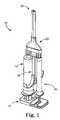
- FIG. 1is a perspective view of one embodiment fluid dispensing system in accordance with principles of the present invention
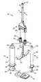
- FIG. 2is an exploded, perspective view of the system of FIG. 1 ;
- FIG. 3is a side view of one embodiment handle assembly assembled to embodiment syringe assemblies of the system of FIG. 1 ;
- FIG. 4is an exploded, perspective view of the handle assembly of FIG. 3 ;
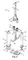
- FIG. 5is an exploded, perspective view of one embodiment manifold assembly of the system of FIG. 1 ;
- FIG. 6is a cut-away, perspective view of embodiment first and second tubes of the manifold assembly of FIG. 5 cut-away along line 6 - 6 of FIG. 5 ;
- FIG. 7is an exploded, perspective view of one embodiment tip assembly of the system of FIG. 1 ;
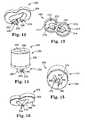
- FIG. 8is a perspective view of one embodiment connecting element of the tip assembly of FIG. 7 ;
- FIG. 9is a bottom view of the connecting element of FIG. 8 ;
- FIG. 10is a perspective view of one embodiment tip element of the tip assembly of FIG. 7 ;
- FIG. 11is a cross-sectional view of the tip element of FIG. 10 ;
- FIG. 12is a perspective view of another embodiment tip element in accordance with the present invention.
- FIG. 13is another perspective view of the tip element of FIG. 12 ;
- FIG. 14is a perspective view of another embodiment tip assembly in accordance with the present invention.
- FIG. 15is another perspective view of the tip assembly of FIG. 14 ;
- FIG. 16is a perspective view of another embodiment tip element in accordance with the present invention.
- FIG. 17is a perspective view of one embodiment kit of parts in accordance with the present invention.
- FIG. 18is a front view of one embodiment tray of the kit of parts of FIG. 17 .
- the fluid dispensing system 10includes a clip assembly 12 , a first syringe assembly 14 , a second syringe assembly 16 , a handle assembly 18 , a manifold assembly 20 , and a tip assembly 22 .
- the clip assembly 12 and handle assembly 18can be grasped and manipulated to simultaneously actuate the first and the second syringe assemblies 14 , 16 to deliver separately maintained fluids (not shown) from the syringe assemblies 14 , 16 through the manifold assembly 20 , and to the tip assembly 22 .
- embodiments of the system 10can provide advantages in mixing the separately maintained fluids upon dispensing them.
- the system 10can be used to dispense reactive therapeutic agents, medicaments, tissue sealants, and/or tissue glues, for example, platelet rich plasma and thrombin.
- the clip assembly 12is configured to allow a user (not shown) to actuate the first syringe assembly 14 and the second syringe assembly 16 simultaneously.
- the first syringe assembly 14 and the second syringe assembly 16can be of a type known in the art, including those used in various types of medical applications.
- the first syringe assembly 14includes a syringe body 24 and a plunger 26 .
- the syringe body 24defines a proximal end 28 , a distal end 30 , and an internal lumen (not shown) having a diameter and configured to maintain a volume of fluid.
- the plunger 26is coaxially received in the internal lumen and defines a proximal end 32 and a distal end (not shown).
- the second syringe assembly 16includes a syringe body 36 and a plunger 38 .
- the syringe body 36defines a proximal end 40 , a distal end 42 , and an internal lumen (not shown) having a diameter and configured to maintain a volume of fluid.
- the plunger 38is coaxially received in the internal lumen and defines a proximal end 44 and a distal end (not shown).
- the first syringe assembly 14maintains a volume of a first fluid (not shown), such as a base fluid, e.g., platelet rich plasma (not shown), while the second syringe assembly 16 separately maintains a volume of a second fluid (not shown), such as an activator fluid, e.g., thrombin.
- a portion of the syringe body 24is color-coded and characterized by a color, for example red, while a portion of the syringe body 36 is characterized by a color, for example white.
- the colors of the syringe bodies 24 , 36can generally correspond to a color of the first and second fluids, respectively.
- the plungers 26 , 38can also be characterized by colors such as those described.
- the first syringe assembly 14is configured to maintain a larger volume of fluid than the second syringe assembly 16 .
- the syringe body 24can define a greater diameter than the syringe body 36 .
- the first syringe assembly 14 and the second syringe assembly 16maintain volumes of the first and second fluids, respectively to define a relative volumetric ratio.
- the volumetric ratio of the first and second syringe assemblies 14 , 16is 1:1; in another, the volumetric ratio is 3:1; in another, the volumetric ratio is 5:1; in another, the volumetric ratio is 10:1; and in yet another, the volumetric ratio is 11:1.
- ratioscan be equally acceptable, for example ratios in a range of 1:1 to 10:1, greater than 11:1, or less than 1:1.
- the system 10is configured to deliver a higher volumetric flow rate of the first fluid (not shown) than a volumetric flow rate of the second fluid (not shown).
- a volumetric flow rate of the second fluidnot shown.
- simultaneous actuation of the plungers 26 and 38results in a higher volumetric flow rate of the first fluid from the syringe assembly 14 than the second fluid from the second syringe assembly 18 .
- the handle assembly 18includes a grasping portion 48 , a longitudinal stem 50 , latitudinal member 52 , a first connector 54 , and a second connector 56 .
- the grasping portion 48extends from the longitudinal stem 50 and can help allow a user to simultaneously impart a force on the grasping portion 48 , for example with a middle finger (not shown) and a ring finger (not shown), and a complementary force on the clip assembly 12 ( FIG. 2 ), for example with a thumb (not shown).
- the longitudinal stem 50defines a longitudinal axis X and, in turn, extends proximally from the latitudinal member 52 .
- the latitudinal member 52extends between a first end 58 and an opposing second end 60 and defines a center between the first and second ends 58 , 60 along a centerline Y.
- the first and second connectors 54 , 56are opposingly located relative to the center at the first and second ends 58 , 60 , respectively of the latitudinal member 52 .
- the longitudinal stem 50extends at an offset from the latitudinal member 52 .
- the longitudinal axis Xcan define an offset distance O D from the centerline Y. From this, it should be understood that the longitudinal stem 50 can also reside at an offset from the center between the first and second connectors 54 , 56 .
- the first and second connectors 54 , 56are configured to receive the distal ends 30 , 42 of the first and second syringe assembly syringe bodies 24 , 36 , respectively.
- the first and second connectors 54 , 56are luer fittings.
- the first connector 54can include a tubular portion 62 and a male fitting 64 .
- the tubular portion 62is formed through the first end 58 of the latitudinal member 52 and defines a fluid passageway for conveying fluid (not shown) from the first syringe assembly 14 .
- the first connector 54is color-coded.
- the male fitting 64can be characterized by a color such as red.
- the second connector 56can also include a tubular portion 66 and a male fitting 68 .
- the tubular portion 66is formed through the second end 60 of the latitudinal member 52 and defines a fluid passageway for conveying the second fluid (not shown).
- the second connector 56is color-coded.
- the male fitting 68can be characterized by a color such as white.
- the longitudinal stem 50is situated at the offset distance O D such that a larger sized syringe body (e.g., syringe body 24 ) can only fit on a predetermined side of the handle assembly 18 .
- the offset distance O Dcan be selected to restrict which syringe body 24 , 36 can be coupled to which of the first and second connectors 54 , 56 .
- the longitudinal stem 50is positioned relative to the first and second connectors 54 , 56 such that the first syringe assembly 14 cannot be coupled to the second connector 56 .
- predetermining to which side the syringe assemblies 14 , 16 are properly connectiblecan ensure that the first fluid (not shown) and the second fluid (not shown) are delivered to an appropriate part of the tip assembly 22 .
- the manifold assembly 20includes a jacket 70 , a first tube 72 , and a second tube 74 .
- the manifold assembly 30is configured to facilitate fluid communication between contents of the first and second syringe assemblies 14 , 16 ( FIG. 2 ) and the tip assembly 22 ( FIG. 2 ).
- the jacket 70includes a hollow sleeve 76 and a mating fixture 78 .
- the sleeve 76is shown slid distally down the first and second tubes 72 , 74 relative to the assembled configuration of the manifold assembly 20 shown in FIG. 2 .
- the hollow sleeve 76defines a proximal end 80 and a distal end 82 .
- the mating fixture 78is configured to be coupled to the proximal end 80 of the hollow sleeve 76 , for example via a snap fit.
- the mating fixture 78includes a first fitting extension 84 , a second fitting extension 86 , and a tube guide 88 .
- the first and second fitting extensions 84 , 86each define an inner lumen (not shown) configured to be fluidly coupled to the first and second tubes 72 , 74 , respectively, and to mate with or otherwise be fluidly coupleable to the first and second connectors 54 , 56 ( FIG. 3 ) of the handle assembly 18 ( FIG. 3 ).
- the tube guide 88is configured to assist in maintaining the first and second tubes 72 , 74 within the hollow sleeve 76 .
- the tube guide 88can be generally v-shaped or otherwise configured to secure and guide the tubes 72 , 74 from a laterally spaced configuration at the proximal end 80 of the hollow sleeve 76 to an adjacent position at the distal end 82 of the hollow sleeve 76 .
- first and second tubes 72 , 74can be described in greater detail.
- the first and second tubes 72 , 74can be distinctly formed, or can be formed jointly, for example with a thin piece of material connecting the first and second tubes together along a portion or entire length of the first and second tubes 72 , 74 .
- the first tube 72can be flexible, rigid, or semi-rigid.
- the first tube 72is semi-rigid, defines a proximal end 90 and a distal end 92 and includes a flexible body 94 and a bendable member 96 that is malleable.
- the flexible body 94defines a first inner lumen 98 configured to receive and convey the first fluid (not shown).
- the flexible body 94defines a second inner lumen (not shown) configured to coaxially receive the bendable member 96 .
- the flexible body 94can be formed over the bendable member 96 such that the second inner lumen is defined upon formation of the flexible body 94 over, or about, the bendable member 96 .
- the bendable member 96can be inserted into the second inner lumen.
- the flexible body 94can be constructed from a flexible, sterilizable material such as PVC or polyurethane.
- An outer diameter of the flexible body 94can be approximately 0.125 inches, although other dimensions are equally acceptable.
- the first inner lumen 98 and/or the second inner lumen (not shown)can define diameters of approximately 0.035 inches, although other dimensions are equally acceptable.
- the flexible body 94can define a variety of lengths for adaptation to specific application needs. As will be described below, in one embodiment, the first tube 72 , including the flexible body 94 and bendable member 96 , can be cut (using surgical scissors, for example) to a desired length.
- the bendable member 96is an elongate and malleable.
- the bendable member 96can be a malleable, re-bendable wire, such as a stainless steel wire.
- the flexible body 94can be provided with a malleable “backbone” to allow selective shaping, or bending of the first tube 72 such that the first tube 72 is semi-rigid. Due to the malleable nature of the bendable member 96 , the flexible body 94 can be selectively repositioned in different orientations which are independently retained by first tube 72 after repositioning.
- the first tube 72can be manually transitioned from a first non-bent state, to semi-rigidly define a first bend (not shown), a second bend (not shown), a third bend (not shown) and so forth.
- the first tube 72can be shaped to facilitate dispensing the first and second fluids (not shown) to a desired location.
- the first tube 72is color-coded and characterized by a color, such as red.
- the flexible body 94 of the second tube 72can be red.
- a reduced diameter first tube 72is desired.
- the flexible body 94can define a single inner lumen (not shown) and be characterized by the absence of the bendable member 96 . In this manner, in one embodiment the first tube 72 can be completely flexible. In terms of use, there are several applications where a longer first tube 72 of a smaller diameter and increased flexibility are preferred (e.g., for vascular insertion or for reaching remote treatment sites).
- the second tube 74is substantially similar to the first tube 72 .
- the second tube 74can also define a proximal end 100 ( FIG. 5 ) and a distal end 102 ( FIG. 5 ) and include a flexible body 104 defining an inner lumen 105 and a bendable member 106 .
- the flexible body 104can similarly be provided a malleable “backbone” via the bendable member 106 to allow selective shaping, or bending of the second tube 74 .
- the bendable member 96 of the first tube 72can alone be used, without use of the bendable member 106 , to allow selective shaping of both the first and the second tubes 72 , 74 .
- the second tube 74is color-coded and characterized by a color, such as white.
- the flexible body 104 of the second tube 74can be white.
- the manifold assembly 20can be assembled as shown in FIG. 2 by fluidly coupling the proximal end 90 of the first tube 72 to the first fitting extension 84 of the mating fixture 78 , and the second tube 74 to the second fitting extension 86 .
- the first and second tubes 72 , 74can be directed out of the distal end 82 of the hollow sleeve 76 .
- the mating fixture 78can then be secured to the proximal end 80 of the hollow sleeve 76 , for example via a snap fit.
- the tip assembly 22includes a connecting element 108 and a tip element 110 .
- the connecting element 108is coupled to the tip element 110 such that the two are in fluid communication.
- the connecting element 108includes a sidewall 112 , and an endwall 114 forming a first distal projection 116 and a second distal projection 118 .
- the sidewall 112 of the connecting element 108defines a first chamber 128 and a second chamber 130 .
- the first chamber 128is open opposite the endwall 114 .
- the first distal projection 116has a hole 132 extending through the endwall 114 to the first chamber 128 .
- a channel 134is formed in the endwall 114 , and in particular the first distal projection 116 , but not through an entirety thereof.
- the channel 134extends tangentially from the hole 132 and defines a cross-sectional area.
- the channel 134is approximately 0.003 to approximately 0.006 inches in width in one embodiment, although other dimensions can be equally acceptable.
- the channel 134is in fluid communication with the first chamber 128 via the hole 132 .
- the hole 132can be a first one of a plurality of holes and the channel 134 can be a first one of a plurality of channels extending tangentially from a corresponding one of the plurality of holes.
- the second chamber 130can be similarly formed to the first chamber 128 with the second chamber 130 open opposite the endwall 114 .
- the second distal projection 118has a hole 136 extending through the endwall 114 to the second chamber 130 .
- a channel 138can also be formed in the endwall 114 , and in particular the distal projection 118 , but not through an entirety thereof.
- the channel 138extends a length tangentially from the hole 136 and defines a cross-sectional area.
- the channel 138is approximately 0.003 to approximately 0.006 inches in width in one embodiment, although other dimensions can be equally acceptable.
- the channel 138is in fluid communication with the second chamber 130 via the hole 136 .
- the hole 136can be a first one of a plurality of holes and the channel 138 can be a first one of a plurality of channels extending tangentially from a corresponding one of the plurality of holes.
- the tip element 110includes a sidewall 140 , an endwall 142 , and a nozzle 144 extending from the endwall 142 .
- the tip element 110can also have a first orifice 146 and a second orifice 148 .
- the sidewall 122can define a first receptacle 150 open opposite the endwall 142 and a second receptacle 152 open opposite the endwall 142 .
- the first receptacle 150 and the first distal projection 116 of the connecting element 108can have complementary shapes, such that the first distal projection 116 is received within the first receptacle 150 of the tip element 110 .
- the second receptacle 152 and the second distal projection 118can also be complementary in nature, such that the second distal projection 118 is receivable within the second receptacle 152 .
- the first orifice 146extends for a length L 1 through the endwall 142 from an origin 154 open to the first receptacle 150 to a terminal end 156 .
- the first orifice 146extends to the terminal end 156 to define a first flow direction D 1 and defines a volume 157 .
- the first orifice 146can taper from the origin 154 to the terminal end 156 .
- a diameter of the first orifice 146 at the origin 154can be greater than a diameter of the first orifice 146 at the terminal end 156 to define a taper. Additional tapers are also contemplated in some embodiments.
- the first orifice 146includes a first taper from a first, larger diameter to a second smaller diameter, and a second taper from the smaller diameter to a third, larger diameter (not shown).
- the terminal end 156 of the first orifice 146is approximately 0.006 inches to approximately 0.020 inches in diameter, although other dimensions can be equally acceptable depending on the volume and type of fluid being atomized, for example. Additionally, the length L 1 can be approximately 0.05 inches, although other dimensions can be equally acceptable.
- the second orifice 148includes a first portion 148 a formed in the endwall 142 and a second portion 148 b formed in the nozzle 144 .
- the first portion 148 adefines an origin 158 of the second orifice 148 and can be described similarly to the first orifice 146 .
- the first portion 148 aextends the length L 1 through the endwall 142 .
- the first portion 148 adefines a taper from a first diameter at the origin 158 through the endwall 142 to a second, smaller diameter.
- the second portion 148 bis formed through the nozzle 144 .
- the nozzle 144extends distally from the endwall 142 at or through an angle ⁇ . In one embodiment, the angle ⁇ is approximately 45 degrees, although other dimensions can be equally acceptable.
- the second portion 148 bextends for a length L 2 to define a terminal end 160 of the second orifice 148 .
- the second portion 148 bextends to the terminal end 160 to define a second flow direction D 2 .
- the second orifice 148including the first and second portions 148 a , 148 b , defines a volume 161 .
- the lengths L 1 , L 2 as well as the diameter(s) of the second orifice 148can be selected to adjust the volume 161 of the second orifice 148 .
- the volume 161 of the second orifice 148is greater than the volume 157 of the first orifice 146 .
- angular extension of nozzle 144results in the terminal end 160 of the second orifice 148 being located or offset distally to the terminal end 156 of the first orifice 146 .
- the first and second orifices 146 , 148and in particular the terminal ends 156 , 160 , each reside in a different plane from the other, such that the two orifices 146 , 148 terminate in different planes.
- the terminal end 160can be located offset and down stream from the terminal end 156 .
- the directions D 1 , D 2can be angularly offset at an angle ⁇ , for example approximately 45 degrees.
- the angle ⁇is approximately 90 degrees such that the directions D 1 , D 2 are substantially perpendicular.
- the two directions D 1 , D 2can intersect at a point P distal the terminal end 156 of the first orifice 146 and spaced laterally from the terminal end 160 of the second orifice 148 .
- the point Pcan be laterally spaced a distance of approximately 0.020 inches from the terminal end 160 , although other dimensions can be equally acceptable.
- the angle ⁇ and length L 2 of the nozzle 144can be selected such that the second fluid (not shown) is delivered from the terminal end 160 of the second orifice 148 into a flow of the first fluid (not shown) from the terminal end 156 of the first orifice 146 .
- the tip assembly 22is assembled by inserting the first distal projection 116 of the connecting element 108 into the first receptacle 150 of the tip element 110 and the second distal projection 118 into the second receptacle 152 .
- the connecting element 108 and tip element 110can be secured together via an interference-type fit, glues, welding, magnets, etc.
- the origin 154 of the first orifice 146is tangentially related to the channel 134 when the connecting element 108 and the tip element 110 are assembled. In this manner, the first orifice 146 of the tip element 110 is in fluid communication with the first chamber 128 of the connecting element 108 .
- the channel 134 and associated plurality of channels of the distal projection 116are tangentially related to the origin 154 of the first orifice 146 .
- the origin 154 of the first orifice 146is centrally located relative to the plurality of channels such that each channel can deliver a tangential flow of fluid to the first origin 154 .
- the channel 138 , as well as the plurality of channels, of the distal projection 118can be similarly in fluid communication with the origin 158 of the second orifice 148 .
- the tangential relationships described abovefacilitate rotational acceleration of the first and the second fluids (not shown) as they move into the origins 154 , 158 of the first and second orifices 146 , 148 respectively.
- the clip assembly 12is fastened to the proximal ends 32 , 44 of the plungers 26 , 38 of the first and second syringe assemblies 14 , 16 , respectively.
- the distal end 30 of the syringe body 24 of the first syringe assembly 12is fluidly coupled to the first connector 54 of the handle assembly 18 .
- the distal end 30is fluidly coupled to the tubular portion 62 of the first connector 54 such that the first syringe assembly 14 is in fluid communication with the tubular portion 62 of handle assembly 18 .
- the distal end 30 of the syringe body 24is screwed over the tubular portion 62 .
- the second syringe assembly 16is similarly coupled to the second connector 56 of the handle assembly 18 .
- first and second connectors 54 , 56 of the handle assembly 18are, in turn, fluidly coupled to the manifold assembly 20 such that the handle assembly 18 is in fluid communication with the manifold assembly 20 .
- the tubular portion 62 of the first connector 54is inserted into the first fitting extension 84 and the male fitting 64 is screwed over the first fitting extension 84 to form a secure fit.
- the tubular portion 62is in fluid communication with the fitting extension 84 , which, in turn, is in fluid communication with the first tube 72 , and in particular the inner lumen 98 ( FIG. 6 ).
- the second connector 56is similarly fluidly coupled to the manifold assembly 20 such that the handle assembly 18 is in fluid communication with the manifold assembly 20 , and in particular the second tube 74 .
- the connectors 54 , 56such as luer fitting-type connectors, allow for quick disconnect, reconnect, and a structurally secure and fluid conveying fit between the syringe assemblies 14 , 16 and the manifold assembly 20 via the handle assembly 18 .
- first and second connectors 58 , 60fluidly couple the handle assembly 18 to the manifold assembly 20 independent of other mechanisms.
- handle assembly 18has been described as defining a fluid passageway, it should be understood that other handle assemblies are also implemented in some embodiments of the present invention such that the first and second syringe assemblies 14 , 16 are directly fluidly coupled to the manifold assembly 20 , for example in a manner similar to that described in U.S. Pat. App. Pub. No. 2003/0233067.
- the distal end 92 of the first tube 72is inserted into the first chamber 128 ( FIG. 8 ) of the connecting element 108 .
- the first tube 72can be retained in the first chamber 128 via an interference-type fit, welds, adhesives, etc.
- the inner lumen 98 ( FIG. 6 )is fluidly coupled with the first chamber 128 .
- the second tube 74can be similarly assembled to the tip assembly 22 via the second chamber 130 ( FIG. 7 ) and in fluid communication therewith.
- the first tube 74 and/or the second tube 76are trimmed to a desired length prior to assembly with the tip assembly 22 .
- the first and second tube assemblies 74 , 76can be cut using surgical scissors to define new distal ends 92 , 102 prior to assembly to the first and second chambers 128 , 130 , respectively.
- a usercan be directed as to the proper assembly of the system 10 in some embodiments of the present invention.
- a usercan be keyed to the proper assembly via the color-coding of various elements described above.
- portions of the handle assembly 18 and the manifold assembly 20are characterized by colors, for example red or white to indicate proper assembly of the system 10 .
- portions of the tip assembly 22 and the first and second syringe assemblies 14 , 16can also be color-coded.
- the color-coding of the elementscorresponds generally to a color characterizing the first and/or second fluids (not shown), respectively.
- a usercan be directed to assemble components of system 10 such that a substantially red-colored fluid is dispensed with portions of the system 10 that are colored red.
- the handle assembly 18can be configured to ensure that a desired one of the syringe assemblies 14 , 16 is connected to a pre-selected one of the connectors 54 , 56 of the manifold assembly 20 .
- a usercan be directed in proper assembly of the system 10 according to from which of the first and the second orifices 146 , 148 each of the first and second fluids should be delivered.
- assembly of the system 10results in the first and second syringe assemblies 14 being in fluid communication with the tip assembly 22 .
- the first syringe assembly 14is in fluid communication with the first orifice 146 ( FIG. 7 ) and the second syringe assembly 16 is in fluid communication with the second orifice 148 ( FIG. 7 ) such that actuation of the plungers 26 , 38 dispense the first and second fluids (not shown) from the first and second orifices 146 , 148 , respectively.
- the first and second fluidscan be dispensed from the first and second orifices 146 , 148 to a desired treatment site (not shown).
- first and second fluids(not shown) to a treatment site (not shown)
- a usersimultaneously actuates the first and second syringe assemblies 14 , 16 by grasping the grasping portion 48 of the handle assembly 18 and pressing on the clip assembly 12 connected to the plungers 26 , 38 .
- the first fluidflows through the hole 132 to the channel 134 and is delivered tangentially to, and into, the origin 154 of the first orifice 146 .
- This tangential relationshipfacilitates rotational acceleration of the first fluid.
- a plurality of channelscan also be implemented to achieve rotational acceleration of the second fluid.
- rotation of the second fluidcan be similarly achieved at the second orifice 148 , with subsequent deceleration occurring in some embodiments.
- the second distal projection 118need not include the channel 138 such that the second fluid can flow from the second chamber 130 , through the hole 136 , and directly into the second orifice 148 .
- simultaneous actuation of the first and second syringe assemblies 14 , 16results in a greater volumetric flow rate of the first fluid (not shown) to the channel 134 of the first distal projection 116 than a volumetric flow rate of the second fluid (not shown) to the channel 138 of the second distal projection 118 .
- Thisin turn, can contribute to greater rotational acceleration (as well as a greater volumetric flow rate) of the first fluid as it enters the origin 154 of the first orifice 146 than the second fluid as it enters the origin 158 of the second orifice 148 .
- the rotational acceleration of the first fluidfacilitates atomization of the first fluid upon exiting the terminal end 156 of the first orifice 146 .
- the amount of fluid rotationcan affect the particle size and distribution of the first fluid as well as the overall, mixed fluid properties of the first fluid.
- the ratio of the cross-sectional area of the channel 134 to the fluid volume, or volumetric flow rate,can affect the amount of rotational acceleration achieved. In other words, a larger volume of fluid flowing through a smaller cross-sectional area can equate to a higher rotational acceleration of the fluid through the cross-sectional area. However, a greater overall volumetric flow rate can be achieved with a larger overall, or “summed,” cross-sectional area.
- one embodimentincorporates more than one channel to optimize rotational acceleration and volumetric flow rates and/or reduce flow resistance in the system 10 .
- rotation methodology for atomizationis described in Chemical Engineer's handbooks such as, Chemical Engineers' Handbook (R. H. Perry & C. H. Chilton eds., 5th ed., McGraw-Hill 1973).
- rotational acceleration of the first and second fluids (not shown) at the origins 154 , 158can be varied by modifying the tip assembly 22 , such as by at least one of the following: modifying a total number of channels, modifying a cross-sectional area of such channels, and modifying the diameters of the first and second orifices 146 , 148 at the origins 154 , 158 .
- the tip element 110is configured to deliver an atomized flow from the first orifice 146 .
- at least one of the taper, the diameter at the origin 154 , the diameter at the terminal end 156 , and the length L 1 of the first orifice 146can be selected to facilitate production of atomized flow from the first orifice 146 .
- other featurescan be added or modified to facilitate production of atomized flow from the first orifice 146 .
- the second fluidenters the channel 138 and flows toward the terminal end 160 of the second orifice 148 at a slow enough rate such that there is minimal to no rotational acceleration.
- the lesser volume fluid flowwill have some rotation but not enough for fluid atomization.
- the second orifice 148can also be configured to facilitate delivery of a bead or stream of fluid to a point where an atomized flow of the first fluid (not shown) is coming from the first orifice 146 .
- the nozzle 144can be configured to assist in decelerating fluid rotation to avoid atomized flow of the second fluid from the second orifice 148 .
- at least one of the taper, the diameter at the origin 158 , the diameter at the terminal end 160 , the lengths L 1 , L 2 of the second orifice 148 , the volume 161 defined by the second orifice 148 , and the angle ⁇ through which the nozzle 144 extendscontribute to rotational deceleration of the second fluid. While the features described above can serve to decrease fluid rotation, or decelerate fluid rotation as it is delivered through the second orifice 148 , it should be understood that in some embodiments other features and mechanisms for facilitating drip flow can be added or modified.
- the useractuates the first and second syringe assemblies 14 , 16 to produce at atomized flow type of the first fluid (not shown) from the terminal end 156 of the first orifice 146 and a non-atomized flow type, such as a drip-flow, of the second fluid (not shown) from the terminal end 160 of the second orifice 148 .
- the nozzle 144can be configured to deliver the second fluid distal or downstream to the first fluid.
- distally offsetting the terminal end 160 to the terminal end 156can allow an atomized flow (or at least a portion thereof) of the first fluid to be delivered in the direction D 1 from the terminal end 156 of the first orifice 146 , travel past the terminal end 160 of the second orifice 158 , and entrain a non-atomized flow of the second fluid from the terminal end 160 of the second orifice 158 .
- the atomized flow of the first fluid“picks up” beads of second fluid resulting in a thorough mixing of the two fluids after exiting the first and second orifices 146 , 148 , respectively.
- first and second fluidsare mixed at a point distal the terminal end 156 of the first orifice 146 but prior to reaching the treatment site (not shown). In another embodiment, the first and second fluids begin mixing proximate the point P ( FIG. 11 ).
- embodiments in accordance with the present inventioncan provide efficient mixing and delivery of the first and second fluids (not shown) to a delivery site (not shown).
- a mixed activator and base(not shown) can be delivered to a site without clogging concerns.
- substantially no cloggingcan be achieved.
- a small “cap”(not shown) is formed at the terminal end 160 of the second orifice 156 after flow of the activator and/or base has ceased.
- the small cap of mixed activator and basecan be readily removed from the second orifice 156 , for example by re-starting flow of the second fluid.
- Another advantagecan reside in not having to deliver the second fluid at a high enough flow rate or rotational acceleration to produce an atomized flow of the second fluid.
- a relatively small amount of the second fluidcan be efficiently delivered without needing to achieve the volumetric flow rates and/or rotational accelerations needed to atomize the second fluid.
- atomization of the second fluidcan be difficult and/or inefficient when delivering the first and second fluids at volumetric ratios greater than 1:1, more difficult and/or inefficient at volumetric ratios greater than or equal to 3:1, and even more difficult at volumetric ratios greater than or equal to 10:1.
- embodiments of the present inventionovercome at least some problems with spray-type dispensers identified in the Background section of this application by directing the lesser volume fluid into the path of the larger volume fluid via an angled nozzle.
- embodimentsinclude offset orifices, which deliver a lesser volume fluid distal to a larger volume fluid.
- the larger volume fluidis atomized as it exits an orifice and impinges on a second, lesser volume fluid. The lesser volume fluid can be picked up by the larger volume fluid, facilitating improved and adequate mixing of the two fluids prior to reaching a treatment site.
- FIGS. 12 and 13show another embodiment tip element 200 in accordance with the present invention.
- the tip element 200includes a nozzle 202 and a sidewall 204 defining a first orifice 206 , a second orifice 208 , a first receptacle 210 , and a second receptacle 212 .
- the first and second receptacles 210 , 212are configured to receive the first distal projection 116 ( FIG. 7 ) and the second distal projection 118 ( FIG. 7 ) of the connecting element 108 ( FIG. 7 ) as previously described in association with other embodiments.
- the first orifice 206is defined by a sidewall portion 213 and defines volume and extends a length from an origin 214 open to the first receptacle 210 to a terminal end 216 .
- the second orifice 210is defined by a sidewall portion 217 and also defines a volume and can extend a length from an origin 218 through the nozzle 202 to a terminal end 220 .
- the terminal end 220is offset distally to the terminal end 216 .
- the first orifice 206can be “shorter” than the second orifice 208 such that the first and second orifices 206 , 208 terminate in a different plane.
- the terminal end 220is distally offset from the terminal end 216 a distance of approximately 0.05 to 0.1 inch, although other dimensions can be equally acceptable.
- the sidewall portions 213 , 217are angled toward one another such that the first and second orifices 206 , 208 are defined to extend angularly toward a common point.
- an angled shape of the first and second orifices 206 , 208assist in directing the first and second fluids (not shown) toward each other as they exit the first and second orifices 206 , 208 , respectively.
- the open volume and/or length of the first and second orifices 206 , 208can reduce rotation and flow rate of the first fluid (not shown) and/or the second fluid (not shown) to aid in ensuring that the first and/or second fluids are not atomized.
- the nozzle 202extends distally to emit a second fluid (not shown) downstream of a first fluid.
- the first fluidcan be dispensed to a point distal from the terminal end 216 to contact a second fluid being dispensed from the terminal end 220 and mix at the terminal end 226 or at a point distal the terminal end 220 .
- a method of dispensing a first and a second fluid (not shown) from the tip element 200includes expelling the first fluid from the shorter, first orifice 206 and the second fluid from the longer, the second orifice 208 .
- the first fluidexits the first orifice 206 and flows over the second orifice 208 where the second fluid is exiting, causing the two liquids to become mixed as they leave the tip element 200 .
- both the first and the second fluidsare expelled from the first and the second orifices 206 , 208 , respectively as a drip-type of flow.
- both the first and the second fluidsare expelled from the first and the second orifices 206 , 208 , respectively as a stream-type of flow.
- one of the first and the second fluidsis expelled as a drip-type of flow and one of the first and second fluids is expelled as a stream-type of flow.
- an offset between the terminal ends 216 , 220can help prevent the second fluid (not shown), e.g., an activator, from entering the first orifice 206 , otherwise contaminating the first fluid (not shown), e.g., a base, or help prevent the first fluid from entering too far into the second orifice 208 , which might otherwise cause undesirable clotting or gelling of the materials.
- the sidewalls 213 , 217can be angled such that the shape of the orifices 206 , 208 assist in directing the first and second fluids toward each other, thereby increasing mixing.
- the tip element 200should illustrate that orifice “offsetting” can be advantageous for applications where atomization of the fluids (not shown) is not necessary, but instead a bead like application of both fluids is to be applied to a treatment site. As described, an offset can improve mixing without compromising toward clotting or gel formation at the terminal ends 216 , 220 . Furthermore, while drip flow from both the first and second orifices 206 , 208 has been described in association with the tip element 200 , it should be noted that in other embodiments, the orifice 208 drips the second fluid while the first orifice 220 atomizes, or sprays the first fluid.
- one embodiment of the connecting element 252includes a sidewall 256 defining a first chamber 258 and a second chamber 260 .
- additional features of the connecting element 252can be similar to the connecting element 108 .
- the tip element 254includes a first nozzle 262 , a second nozzle 264 , and a third nozzle 266 .
- the tip element 254also defines a first orifice 268 , a second orifice 270 , a third orifice 272 , and a fourth orifice 274 .
- the first, second and third orifices 268 , 270 , 272extend through the first, second, and third nozzles 262 , 264 , 266 , respectively.
- the fourth orifice 274can formed to be substantially similar to the first orifice 146 of the tip element 110 .
- the tip element 254is configured to facilitate production of atomized and/or non-atomized flow combinations from the first, second, third, and fourth orifices 268 , 270 , 272 , 274 according to the principles and embodiments previously described in association with the tip assembly 22 .
- the tip element 254is configured to provide different emission characteristics, or flow types, from the orifices 268 , 270 , 272 , 274 , such as drip, stream, or spray.
- the connecting element 252 and the tip element 254are configured, or otherwise sized, shaped, and arranged to be rotated relative to one another to dispose the first and second chambers 258 , 260 “over” the first and third orifices 268 , 272 .
- the tip assembly 250can dispense a “drip-drip” flow of the first and second fluids (not shown).
- the connecting element 252 and the tip element 254can also be rotated to dispose the first chamber 258 “over” the second and fourth orifices 270 , 274 .
- the tip assembly 250can deliver a “spray-drip” flow of the first and second fluids.
- a usercan select what combination of flow types (e.g. spray, drip, or stream) is to be applied.
- flow typese.g. spray, drip, or stream
- atomized or spray, drip, and stream types of floware selectively interchanged according to a desire to utilize multiple fluid application modes on a patient without changing between tip assemblies.
- FIG. 16shows another embodiment tip element 300 in accordance with the present invention.
- the tip element 300includes a sidewall 302 , an endwall 304 , and a nozzle 306 extending from the end wall 304 .
- the tip element 300also has a single orifice 308 extending through the nozzle 306 and the end wall 304 .
- the sidewall 302defines a first receptacle (not shown) and a second receptacle (not shown) configured to receive the first and second distal projections 116 , 118 ( FIG. 7 ) of the connecting element 108 ( FIG. 7 ) as previously described in association with other embodiments.
- the orifice 308defines an origin (not shown) and a terminal end 310 , the orifice 308 tapering in width from the origin to the terminal end 310 .
- the origin (not shown)is open to both the first and the second receptacles (not shown) of the tip element 300 .
- the orifice 308can be in fluid communication with both the first chamber 128 ( FIG. 8 ) and the second chamber 130 ( FIG. 8 ) of the connecting element 108 ( FIG. 8 ).
- the pluralities of channels ( FIG. 7 ) associated with the first and second distal projections 116 , 118 ( FIG. 7 )deliver both the first and second fluids (not shown) to the origin of the orifice 308 .
- Rotational acceleration of the fluids and/or the taper of the orifice 308can facilitate effective mixing of the two fluids within the orifice 308 prior to being delivered from the terminal end 310 .
- embodiments of the tip element 300provide advantages in mixing two fluids prior to being delivered from the tip element 300 .
- thismight be desirable in applications where a reaction time of two fluids is extended and earlier mixing is otherwise desirable to decrease reaction time following delivery from the tip element 300 .
- kits of parts 400 associated with the fluid dispensing system 10includes a first syringe assembly 402 , a second syringe assembly 404 , a plurality of specimen cups 405 including a first specimen cup 406 and a second specimen cup 408 , and a tray 410 .
- the first and second syringe assemblies 402 , 404are similar to embodiments of the first and second syringe assemblies 14 , 16 ( FIG. 1 ) as previously described.
- the plurality of specimen cups 405can be a type commonly used in such applications.
- the tray 410is shown in greater detail in FIG. 18 .
- the tray 410includes a body 412 defining a bottom support surface 414 and plurality of pockets including a pocket 416 .
- the bottom support surface 414is configured to support the tray 410 in a horizontal position, for example on a horizontal surface 418 .
- the pocket 416defines a base 420 and a sidewall 422 .
- the base 420 and the sidewall 422are configured to maintain the first specimen cup 406 ( FIG. 16 ) in a vertically tipped position as described in greater detail below.
- the base 420is offset at an angle ⁇ relative to the horizontal position of the tray 410 . In one embodiment, the angle ⁇ is approximately 5 degrees to approximately 10 degrees, although other dimensions can be equally acceptable.
- the first specimen cup 406( FIG. 17 ) is placed into the pocket 416 and supported at the angle ⁇ .
- the first specimen cup 406can be supported in tipped position relative to the horizontal position of the tray 410 .
- the pocket 416is configured to aid in ease of removing contents of the first specimen cup 406 without requiring manual manipulation of the first specimen cup 406 or the tray 410 .
- the first specimen cup 406is filled with the first fluid (not shown) and the second specimen cup 408 is filled with the second fluid (not shown).
- a userthen draws the first fluid from the first specimen cup 406 as supported in the tipped position using the first syringe assembly 402 .
- the usercan draw substantially all of the first fluid (not shown) from first specimen cup 402 without having to manually tip the first specimen cup 406 or the tray 410 .
- the second specimen cup 408is maintained in a second pocket (not show) in a tipped position in a similar manner to that described above.
- the second specimen cup 408is filled with the second fluid and the user can draw substantially all of the second fluid from the second specimen cup 408 without having to manually tip the second specimen cup 408 or the tray 410 .
- each of the pockets making up the plurality of pocketsis configured to hold a corresponding one of the cups 405 in an angled or tipped position.
- the tray 410can be formed from a semi rigid material, such as a polymeric material (e.g., polystyrene, polyester, and PVC). Additionally, other accessories may also optionally be included in embodiments of the kit of parts 400 .
- the kit of parts 400includes pluralities of syringe assemblies and specimen cups, clip assemblies (not shown), handle assemblies (not shown), manifold assemblies (not shown), tip assemblies (not shown) and/or other specific procedure-related components.
- the various embodiment components of the fluid dispensing system 10can be provided in different states of assembly to afford customization or modification to meet the particular desires of a user.
- kits of parts 400 of the present inventionmay be packaged together, separately, or in subassemblies depending on a variety of factors such as shelf life and sterilization requirements. They may be assembled at a manufacturing location or at a healthcare location. Any suitable sterilization procedure may be utilized to sterilize the contents of the kit of parts 400 . Suitable sterilization techniques include, but are not limited to steam, ethylene oxide, electron beam, vapor (e.g., hydrogen peroxide or peracetic acid), or plasma procedures, for example.
Landscapes
- Health & Medical Sciences (AREA)
- Life Sciences & Earth Sciences (AREA)
- Heart & Thoracic Surgery (AREA)
- Animal Behavior & Ethology (AREA)
- Surgery (AREA)
- Veterinary Medicine (AREA)
- Engineering & Computer Science (AREA)
- Biomedical Technology (AREA)
- Public Health (AREA)
- General Health & Medical Sciences (AREA)
- Molecular Biology (AREA)
- Nuclear Medicine, Radiotherapy & Molecular Imaging (AREA)
- Medical Informatics (AREA)
- Chemical & Material Sciences (AREA)
- Chemical Kinetics & Catalysis (AREA)
- Vascular Medicine (AREA)
- Anesthesiology (AREA)
- Hematology (AREA)
- Infusion, Injection, And Reservoir Apparatuses (AREA)
Abstract
Description
Claims (9)
Priority Applications (2)
| Application Number | Priority Date | Filing Date | Title |
|---|---|---|---|
| US11/341,153US7635343B2 (en) | 2005-04-21 | 2006-01-27 | Fluid dispenser |
| US12/592,435US8088099B2 (en) | 2005-04-21 | 2009-11-23 | Fluid dispenser |
Applications Claiming Priority (2)
| Application Number | Priority Date | Filing Date | Title |
|---|---|---|---|
| US67370105P | 2005-04-21 | 2005-04-21 | |
| US11/341,153US7635343B2 (en) | 2005-04-21 | 2006-01-27 | Fluid dispenser |
Related Child Applications (1)
| Application Number | Title | Priority Date | Filing Date |
|---|---|---|---|
| US12/592,435DivisionUS8088099B2 (en) | 2005-04-21 | 2009-11-23 | Fluid dispenser |
Publications (2)
| Publication Number | Publication Date |
|---|---|
| US20060253082A1 US20060253082A1 (en) | 2006-11-09 |
| US7635343B2true US7635343B2 (en) | 2009-12-22 |
Family
ID=37394974
Family Applications (2)
| Application Number | Title | Priority Date | Filing Date |
|---|---|---|---|
| US11/341,153Active - Reinstated2028-06-02US7635343B2 (en) | 2005-04-21 | 2006-01-27 | Fluid dispenser |
| US12/592,435ActiveUS8088099B2 (en) | 2005-04-21 | 2009-11-23 | Fluid dispenser |
Family Applications After (1)
| Application Number | Title | Priority Date | Filing Date |
|---|---|---|---|
| US12/592,435ActiveUS8088099B2 (en) | 2005-04-21 | 2009-11-23 | Fluid dispenser |
Country Status (1)
| Country | Link |
|---|---|
| US (2) | US7635343B2 (en) |
Cited By (24)
| Publication number | Priority date | Publication date | Assignee | Title |
|---|---|---|---|---|
| US20090076459A1 (en)* | 2005-11-22 | 2009-03-19 | Edit Goldberg | Applicator device for applying a multi-component fluid |
| US20090230214A1 (en)* | 2006-05-17 | 2009-09-17 | Medmix System Ag | Dispensing Device with a Spray Assembly |
| WO2013121429A1 (en) | 2012-02-16 | 2013-08-22 | Ramot At Tel-Aviv University Ltd. | Formulations and kits for forming bioadhesive matrices |
| US20140058442A1 (en)* | 2012-08-24 | 2014-02-27 | St. Jude Medical Puerto Rico Llc | Sealant storage, preparation, and delivery systems and related methods |
| US8870028B2 (en) | 2012-05-25 | 2014-10-28 | Restek Corporation | Dispensing device |
| US8974436B2 (en) | 2011-10-28 | 2015-03-10 | Medtronic Xomed, Inc. | Multi-sectioned cannula with multiple lumens |
| US8998866B2 (en) | 2010-07-02 | 2015-04-07 | Smith & Nephew Plc | Provision of wound filler |
| US20150335397A1 (en)* | 2013-04-09 | 2015-11-26 | Ivoclar Vivadent Ag | Syringe |
| US9387126B2 (en) | 2002-10-28 | 2016-07-12 | Smith & Nephew Plc | Apparatus for aspirating, irrigating and cleansing wounds |
| US9486190B2 (en) | 2011-10-28 | 2016-11-08 | Medtronic Xomed, Inc. | Spray delivery system |
| US9572555B1 (en)* | 2015-09-24 | 2017-02-21 | Ethicon, Inc. | Spray or drip tips having multiple outlet channels |
| USD829888S1 (en) | 2015-12-22 | 2018-10-02 | Guangzhou Bioseal Biotech Co., Ltd. | Reconstitution and delivery device |
| US20180361065A1 (en)* | 2015-12-22 | 2018-12-20 | Guangzhou Bioseal Biotech Co. Ltd. | Dual Syringe with Funnel Feeding Kit |
| CN109481789A (en)* | 2018-12-30 | 2019-03-19 | 杨霞 | Attachment base for muscle syringe |
| US10441959B2 (en) | 2011-10-28 | 2019-10-15 | Medtronic Xomed, Inc. | Multi-orifice spray head |
| US10537657B2 (en) | 2010-11-25 | 2020-01-21 | Smith & Nephew Plc | Composition I-II and products and uses thereof |
| USD877890S1 (en) | 2015-12-22 | 2020-03-10 | Guangzhou Bioseal Biotech Co., Ltd. | Reconstitution device |
| USD877891S1 (en) | 2015-12-22 | 2020-03-10 | Guangzhou Bioseal Biotech Co., Ltd. | Reconstitution and delivery device |
| US11173246B2 (en)* | 2016-07-22 | 2021-11-16 | Isto Technologies, Inc. | Multi-component injection system and methods for tissue repair |
| US11504517B2 (en) | 2015-12-11 | 2022-11-22 | Nxstage Medical, Inc. | Fluid line connector devices methods and systems |
| US11638666B2 (en) | 2011-11-25 | 2023-05-02 | Smith & Nephew Plc | Composition, apparatus, kit and method and uses thereof |
| US11931226B2 (en) | 2013-03-15 | 2024-03-19 | Smith & Nephew Plc | Wound dressing sealant and use thereof |
| US11938231B2 (en) | 2010-11-25 | 2024-03-26 | Smith & Nephew Plc | Compositions I-I and products and uses thereof |
| US12350129B2 (en) | 2013-03-15 | 2025-07-08 | Smith & Nephew Plc | Wound dressing sealant and use thereof |
Families Citing this family (34)
| Publication number | Priority date | Publication date | Assignee | Title |
|---|---|---|---|---|
| US7699803B2 (en)* | 2007-01-03 | 2010-04-20 | Medtronic Vascular, Inc. | Devices and methods for injection of multiple-component therapies |
| GB0707758D0 (en)* | 2007-04-21 | 2007-05-30 | Smith & Nephew | A foam material for medical use and method for producing same |
| WO2008153059A1 (en)* | 2007-06-15 | 2008-12-18 | Juridical Foundation The Chemo-Sero-Therapeutic Research Institute | Spray head, applicator for applying biological tissue bonding agent, and method of applying bonding agent |
| WO2009067711A2 (en) | 2007-11-21 | 2009-05-28 | T.J. Smith & Nephew, Limited | Suction device and dressing |
| ES2715605T3 (en) | 2007-11-21 | 2019-06-05 | Smith & Nephew | Wound dressing |
| GB0722820D0 (en) | 2007-11-21 | 2008-01-02 | Smith & Nephew | Vacuum assisted wound dressing |
| US11253399B2 (en) | 2007-12-06 | 2022-02-22 | Smith & Nephew Plc | Wound filling apparatuses and methods |
| US20130096518A1 (en) | 2007-12-06 | 2013-04-18 | Smith & Nephew Plc | Wound filling apparatuses and methods |
| GB0723875D0 (en) | 2007-12-06 | 2008-01-16 | Smith & Nephew | Wound management |
| EP2247243B1 (en)* | 2008-01-28 | 2019-05-15 | Baxter International Inc. | Sealant application with malleable section |
| GB0803564D0 (en) | 2008-02-27 | 2008-04-02 | Smith & Nephew | Fluid collection |
| US20090320856A1 (en)* | 2008-06-30 | 2009-12-31 | John Brewer | Sealant Applicator and Method |
| GB0902354D0 (en)* | 2009-02-13 | 2009-04-01 | 3M Innovative Properties Co | Syringes for dispensing multicomponent material |
| MY159833A (en)* | 2009-08-19 | 2017-02-15 | Unilever Plc | A process and a device to clean substrates |
| US9445795B2 (en)* | 2009-10-16 | 2016-09-20 | Confluent Surgical, Inc. | Prevention of premature gelling of delivery devices for pH dependent forming materials |
| US20110092918A1 (en)* | 2009-10-19 | 2011-04-21 | Ferrosan A/S | Malleable tip for applying an agent to a target site |
| US9061095B2 (en) | 2010-04-27 | 2015-06-23 | Smith & Nephew Plc | Wound dressing and method of use |
| US8834418B2 (en)* | 2010-07-22 | 2014-09-16 | Covidien Lp | Molds for in situ forming materials |
| AU2010101255B4 (en)* | 2010-11-15 | 2011-09-22 | Lumsden, Andrew | A prefilled syringe for administering buffered lignocaine |
| USD726304S1 (en)* | 2012-03-22 | 2015-04-07 | Terumo Kabushiki Kaisha | Medicament sprayer |
| CN204485033U (en)* | 2012-03-27 | 2015-07-22 | 泰尔茂株式会社 | Guide |
| US9242846B2 (en) | 2012-04-13 | 2016-01-26 | Rooftop Research, Llc | Vee manifold |
| WO2014200331A1 (en)* | 2013-06-10 | 2014-12-18 | Recuperate Medical B.V. | Syringe pair assembly for biological fluids |
| US10085729B2 (en)* | 2014-03-06 | 2018-10-02 | Ethicon, Inc. | Methods and devices for forming biomedical coatings using variable mixing ratios of multi-part compositions |
| EP3197372B1 (en)* | 2014-09-22 | 2023-03-15 | Arsenal Medical, Inc. | Devices and systems for filling body cavities |
| US10737058B2 (en) | 2016-12-28 | 2020-08-11 | Ethicon Llc | Rigid and flexible laparoscopic multiple component material dispensing devices and methods |
| USD893714S1 (en) | 2018-02-14 | 2020-08-18 | Ethicon Llc | Laparoscopic adaptor |
| US11352247B2 (en) | 2018-08-24 | 2022-06-07 | Rooftop Research, Llc | Manifold and fluid dispensing systems |
| CN113226228A (en)* | 2018-10-26 | 2021-08-06 | 新加坡保健服务集团有限公司 | Device and method for ophthalmic extraction and injection |
| US11358165B2 (en) | 2019-10-04 | 2022-06-14 | Ethicon, Inc. | Spray devices having side-by-side spray tips for dispensing two fluids that chemically react together |
| US12207810B2 (en) | 2019-10-04 | 2025-01-28 | Ethicon, Inc. | Dispensing systems and devices having anti-clogging spray tips for dispensing two or more fluids that react together |
| KR20230066396A (en)* | 2020-09-09 | 2023-05-15 | 보스톤 싸이엔티픽 싸이메드 인코포레이티드 | pharmaceutical delivery device |
| US12409271B2 (en)* | 2022-04-25 | 2025-09-09 | Frank Levy | Apparatus and method for producing an enriched medical suspension |
| CN115365028A (en)* | 2022-09-01 | 2022-11-22 | 上海利格泰医用设备有限公司 | PRP injection device |
Citations (78)
| Publication number | Priority date | Publication date | Assignee | Title |
|---|---|---|---|---|
| US2112160A (en) | 1933-04-04 | 1938-03-22 | Kenneth Fredericks | Method of and apparatus for effecting medicinal treatment |
| US3223083A (en) | 1960-09-09 | 1965-12-14 | President And Directors Of Geo | Method for adhesively securing together skin and other soft tissue and bone |
| US3467096A (en) | 1966-04-12 | 1969-09-16 | Ferrell S Horn | Multiple hypodermic syringe arrangement |
| US3767085A (en)* | 1971-08-02 | 1973-10-23 | J Cannon | Mixing syringe |
| US3828980A (en)* | 1972-11-06 | 1974-08-13 | Chem Dev Corp | Dispenser for precisely metered dispensing of viscous fluids |
| US4040420A (en) | 1976-04-22 | 1977-08-09 | General Dynamics | Packaging and dispensing kit |
| US4090129A (en)* | 1977-01-28 | 1978-05-16 | University Of Virginia | Stopped-flow reaction apparatus utilized in conjunction with continuous-flow resistive-particle counting apparatus |
| US4109653A (en) | 1977-02-22 | 1978-08-29 | George Kozam | Successive delivery multiple barrel syringe |
| US4121739A (en)* | 1977-04-20 | 1978-10-24 | Illinois Tool Works Inc. | Dispenser with unitary plunger and seal construction |
| US4359049A (en) | 1980-04-02 | 1982-11-16 | Immuno Aktiengesellschaft Fur Chemisch-Medizinische Produkte | Apparatus for applying a tissue adhesive on the basis of human or animal proteins |
| US4367737A (en)* | 1981-04-06 | 1983-01-11 | George Kozam | Multiple barrel syringe |
| US4471765A (en)* | 1980-09-25 | 1984-09-18 | The Massachusetts General Hospital | Apparatus for radiolabeling red blood cells |
| US4609371A (en) | 1985-06-24 | 1986-09-02 | Pizzino Joanne L | Dual syringe for either simultaneous or sequential injection of liquids |
| US4631055A (en) | 1984-03-29 | 1986-12-23 | Immuno Aktiengesellschaft Fur Chemisch-Medizinische Produkte | Apparatus for applying a tissue adhesive |
| US4735616A (en) | 1985-06-20 | 1988-04-05 | Immuno Aktiengesellschaft Fur Chemisch-Medizinische Produkte | Arrangement for applying a tissue adhesive |
| US4753536A (en)* | 1987-03-09 | 1988-06-28 | Spehar Edward R | Dispensing mixer for the storage and mixing of separate materials |
| US4874368A (en) | 1988-07-25 | 1989-10-17 | Micromedics, Inc. | Fibrin glue delivery system |
| US4978336A (en) | 1987-09-29 | 1990-12-18 | Hemaedics, Inc. | Biological syringe system |
| US4979942A (en) | 1989-10-16 | 1990-12-25 | Johnson & Johnson Medical, Inc. | Two component syringe delivery system |
| US5049135A (en)* | 1990-09-18 | 1991-09-17 | Code Blue Medical Corporation | Medical lavage apparatus |
| US5104375A (en) | 1989-10-16 | 1992-04-14 | Johnson & Johnson Medical, Inc. | Locking holder for a pair of syringes and method of use |
| US5116315A (en) | 1989-10-03 | 1992-05-26 | Hemaedics, Inc. | Biological syringe system |
| US5185001A (en) | 1990-01-18 | 1993-02-09 | The Research Foundation Of State University Of New York | Method of preparing autologous plasma fibrin and application apparatus therefor |
| US5290259A (en) | 1993-02-18 | 1994-03-01 | Ultradent Products, Inc. | Double syringe delivery system |
| US5322510A (en) | 1989-11-21 | 1994-06-21 | Andreas Lindner | Injection apparatus |
| US5368563A (en) | 1991-12-18 | 1994-11-29 | Micromedics, Inc. | Sprayer assembly for physiologic glue |
| US5376079A (en) | 1991-09-30 | 1994-12-27 | Holm; Niels E. | Dispensing device for dispensing at least two fluids |
| US5445614A (en) | 1993-10-20 | 1995-08-29 | Habley Medical Technology Corporation | Pharmaceutical storage and mixing syringe |
| US5464396A (en) | 1993-10-18 | 1995-11-07 | Immuno Ag | Syringe assembly for the storage and application of a biological multi-component material |
| WO1995031137A1 (en) | 1994-05-18 | 1995-11-23 | Omrix Biopharmaceuticals S.A. | Dispenser for a multi-component tissue adhesive |
| US5474540A (en) | 1994-03-25 | 1995-12-12 | Micromedics, Inc. | Fluid separation control attachment for physiologic glue applicator |
| FR2722104A3 (en) | 1994-07-05 | 1996-01-12 | Immuno Ag | Catheter adaptor sleeve |
| US5542934A (en) | 1995-06-02 | 1996-08-06 | Silver; Richard M. | Multiple carpule hypodermic syringe |
| US5582596A (en) | 1992-09-26 | 1996-12-10 | Juridical Foundation The Chemo-Sero-Therapeutic Research Institute | Applicator for applying a biocompatible adhesive |
| US5584815A (en) | 1993-04-02 | 1996-12-17 | Eli Lilly And Company | Multi-cartridge medication injection device |
| US5605255A (en) | 1994-06-28 | 1997-02-25 | Behringwerke Aktiengesellschaft | Apparatus for spraying a mixture of two components |
| US5643206A (en) | 1993-09-03 | 1997-07-01 | Ultradent Products, Inc. | Methods and apparatus for mixing and dispensing multi-part compositions |
| US5665067A (en) | 1994-02-28 | 1997-09-09 | Immuno Aktiengesellschaft | Apparatus for applying a multiple-component tissue adhesive |
| US5725499A (en) | 1994-05-11 | 1998-03-10 | Plas-Pak Industries, Inc. | Dual barreled syringe and methods of assembly and use |
| US5759171A (en)* | 1996-09-27 | 1998-06-02 | Thermogenesis Corp. | Sprayer for fibrin glue |
| US5814022A (en) | 1996-02-06 | 1998-09-29 | Plasmaseal Llc | Method and apparatus for applying tissue sealant |
| US5851169A (en) | 1996-01-31 | 1998-12-22 | Medtronic Electromedics, Inc. | Rotary plate and bowl clamp for blood centrifuge |
| US5887755A (en) | 1995-06-06 | 1999-03-30 | Quantic Biomedical Partners | Wound sealant preparation and application device and method |
| US5935437A (en)* | 1995-03-24 | 1999-08-10 | Johnson & Johnson Medical, Inc. | Preparation of autologous plasma and fibrin gel |
| US5975367A (en) | 1996-09-27 | 1999-11-02 | Thermogenesis Corp. | Fibrin glue line and dot dispenser |
| US5989215A (en) | 1995-01-16 | 1999-11-23 | Baxter International Inc. | Fibrin delivery device and method for forming fibrin on a surface |
| WO2000016698A1 (en) | 1998-09-18 | 2000-03-30 | Imedex Biomateriaux | Device for forming and delivering a mixture |
| US6059749A (en)* | 1996-03-13 | 2000-05-09 | New York Blood Center | Fibrin sealant glue-gun with insertable compressed gas cartridge and luer-type reservoir connectors |
| US6113571A (en) | 1996-09-10 | 2000-09-05 | Omrix Biopharmaceuticals S.A. | Applicator device for applying a multiple component fluid |
| US6234994B1 (en) | 1996-09-10 | 2001-05-22 | Omrix Biopharmaceuticals Sa | Multicomponent tissue adhesive application device and holder for such device |
| US20010031948A1 (en)* | 1998-08-26 | 2001-10-18 | Neomend, Inc. | Systems and methods for applying cross-linked mechanical barriers |
| US20020004038A1 (en) | 1996-04-30 | 2002-01-10 | Baugh Robert F. | Autologous platelet gel spray delivery system |
| US20020032463A1 (en)* | 1998-11-06 | 2002-03-14 | Gregory M. Cruise | Compositions, systems, and methods for arresting or controlling bleeding or fluid leakage in body tissue |
| US6394982B1 (en) | 1997-07-11 | 2002-05-28 | United States Surgical Corporation | Fibrin glue applicator system |
| US6444228B1 (en) | 1996-04-30 | 2002-09-03 | Medtronic, Inc. | Autologous fibrin sealant and method for making the same |
| US6454739B1 (en) | 1999-09-13 | 2002-09-24 | Korea Greencross Corp. | Fibrin sealant delivery device |
| US20020138038A1 (en)* | 2001-01-12 | 2002-09-26 | Olle Ljungquist | Device and method for dispensing at least two mutually reactive components |
| US6475175B1 (en) | 1996-01-31 | 2002-11-05 | John Rivera | Method and apparatus for sequestering platelet rich plasma |
| US6589153B2 (en) | 2001-09-24 | 2003-07-08 | Medtronic, Inc. | Blood centrifuge with exterior mounted, self-balancing collection chambers |
| US6610033B1 (en)* | 2000-10-13 | 2003-08-26 | Incept, Llc | Dual component medicinal polymer delivery system and methods of use |
| US6612975B2 (en) | 2001-04-09 | 2003-09-02 | Medtronic, Inc. | Blood centrifuge with an enhanced internal drive assembly |
| US20030187408A1 (en)* | 2002-03-27 | 2003-10-02 | Gerard Marx | Fibrin applicator pistol |
| US20030233067A1 (en) | 2002-06-14 | 2003-12-18 | Mcintosh Kevin D. | Multiple ratio fluid dispenser |
| US20030232712A1 (en) | 2002-06-14 | 2003-12-18 | Dolecek Victor D. | Centrifuge system utilizing disposable components and automated processing of blood to collect platelet rich plasma |
| US20040055937A1 (en) | 2001-04-09 | 2004-03-25 | Dolecek Victor D. | Blood centrifuge having overhanging disposable blood container |
| US6732887B2 (en)* | 2002-03-26 | 2004-05-11 | Ultradent Products, Inc. | Two-part composition syringe delivery system |
| US20040167617A1 (en)* | 2001-01-26 | 2004-08-26 | Voellmicke John C. | Graft delivery system |
| US6852099B2 (en)* | 2002-06-04 | 2005-02-08 | Baxter International Inc. | Device for controllably applying liquids to body surfaces |
| US6884230B1 (en)* | 1998-03-09 | 2005-04-26 | Baxter International Inc. | Dispensing head for a tissue sealant applicator and process of use |
| US20050096588A1 (en)* | 2003-10-31 | 2005-05-05 | Adam Hagmann | Laparoscopic spray device and method of use |
| US6921381B2 (en)* | 2001-10-05 | 2005-07-26 | Baxter International Inc. | Laparoscopic spray device and method of use |
| US6939329B1 (en)* | 1999-10-08 | 2005-09-06 | Harvest Technologies Corporation | Apparatus for holding and operating one or more syringes |
| US6972005B2 (en)* | 2002-05-10 | 2005-12-06 | Boehm Jr Frank H | Dual chamber syringe and dual lumen needle |
| US7081103B2 (en)* | 1998-06-03 | 2006-07-25 | Baxter International Inc. | Direct dual filling device for sealing agents |
| US7322956B2 (en)* | 2003-07-15 | 2008-01-29 | Straumann Holding, Ab | System and method for mixing at least four components |
| US20080161772A1 (en)* | 2007-01-03 | 2008-07-03 | Medtronic Vascular, Inc. | Devices and Methods for Injection of Multiple-Component Therapies |
| US20080167621A1 (en)* | 2005-05-16 | 2008-07-10 | Wagner Gary S | Multi-Barrel Syringe Having Integral Manifold |
| US20090076459A1 (en)* | 2005-11-22 | 2009-03-19 | Edit Goldberg | Applicator device for applying a multi-component fluid |
- 2006
- 2006-01-27USUS11/341,153patent/US7635343B2/enactiveActive - Reinstated
- 2009
- 2009-11-23USUS12/592,435patent/US8088099B2/enactiveActive
Patent Citations (91)
| Publication number | Priority date | Publication date | Assignee | Title |
|---|---|---|---|---|
| US2112160A (en) | 1933-04-04 | 1938-03-22 | Kenneth Fredericks | Method of and apparatus for effecting medicinal treatment |
| US3223083A (en) | 1960-09-09 | 1965-12-14 | President And Directors Of Geo | Method for adhesively securing together skin and other soft tissue and bone |
| US3467096A (en) | 1966-04-12 | 1969-09-16 | Ferrell S Horn | Multiple hypodermic syringe arrangement |
| US3767085A (en)* | 1971-08-02 | 1973-10-23 | J Cannon | Mixing syringe |
| US3828980A (en)* | 1972-11-06 | 1974-08-13 | Chem Dev Corp | Dispenser for precisely metered dispensing of viscous fluids |
| US4040420A (en) | 1976-04-22 | 1977-08-09 | General Dynamics | Packaging and dispensing kit |
| US4090129A (en)* | 1977-01-28 | 1978-05-16 | University Of Virginia | Stopped-flow reaction apparatus utilized in conjunction with continuous-flow resistive-particle counting apparatus |
| US4109653A (en) | 1977-02-22 | 1978-08-29 | George Kozam | Successive delivery multiple barrel syringe |
| US4121739A (en)* | 1977-04-20 | 1978-10-24 | Illinois Tool Works Inc. | Dispenser with unitary plunger and seal construction |
| US4359049A (en) | 1980-04-02 | 1982-11-16 | Immuno Aktiengesellschaft Fur Chemisch-Medizinische Produkte | Apparatus for applying a tissue adhesive on the basis of human or animal proteins |
| US4471765A (en)* | 1980-09-25 | 1984-09-18 | The Massachusetts General Hospital | Apparatus for radiolabeling red blood cells |
| US4367737A (en)* | 1981-04-06 | 1983-01-11 | George Kozam | Multiple barrel syringe |
| US4631055A (en) | 1984-03-29 | 1986-12-23 | Immuno Aktiengesellschaft Fur Chemisch-Medizinische Produkte | Apparatus for applying a tissue adhesive |
| US4735616A (en) | 1985-06-20 | 1988-04-05 | Immuno Aktiengesellschaft Fur Chemisch-Medizinische Produkte | Arrangement for applying a tissue adhesive |
| US4609371A (en) | 1985-06-24 | 1986-09-02 | Pizzino Joanne L | Dual syringe for either simultaneous or sequential injection of liquids |
| US4753536A (en)* | 1987-03-09 | 1988-06-28 | Spehar Edward R | Dispensing mixer for the storage and mixing of separate materials |
| US4978336A (en) | 1987-09-29 | 1990-12-18 | Hemaedics, Inc. | Biological syringe system |
| US4874368A (en) | 1988-07-25 | 1989-10-17 | Micromedics, Inc. | Fibrin glue delivery system |
| US5116315A (en) | 1989-10-03 | 1992-05-26 | Hemaedics, Inc. | Biological syringe system |
| US5104375A (en) | 1989-10-16 | 1992-04-14 | Johnson & Johnson Medical, Inc. | Locking holder for a pair of syringes and method of use |
| US4979942A (en) | 1989-10-16 | 1990-12-25 | Johnson & Johnson Medical, Inc. | Two component syringe delivery system |
| US5322510A (en) | 1989-11-21 | 1994-06-21 | Andreas Lindner | Injection apparatus |
| US5185001A (en) | 1990-01-18 | 1993-02-09 | The Research Foundation Of State University Of New York | Method of preparing autologous plasma fibrin and application apparatus therefor |
| US5049135A (en)* | 1990-09-18 | 1991-09-17 | Code Blue Medical Corporation | Medical lavage apparatus |
| US5520658A (en) | 1991-09-30 | 1996-05-28 | E. R. Squibb & Sons, Inc. | Dispensing device for dispensing at least two fluids |
| US5376079A (en) | 1991-09-30 | 1994-12-27 | Holm; Niels E. | Dispensing device for dispensing at least two fluids |
| US5368563A (en) | 1991-12-18 | 1994-11-29 | Micromedics, Inc. | Sprayer assembly for physiologic glue |
| US5582596A (en) | 1992-09-26 | 1996-12-10 | Juridical Foundation The Chemo-Sero-Therapeutic Research Institute | Applicator for applying a biocompatible adhesive |
| US5290259A (en) | 1993-02-18 | 1994-03-01 | Ultradent Products, Inc. | Double syringe delivery system |
| US5584815A (en) | 1993-04-02 | 1996-12-17 | Eli Lilly And Company | Multi-cartridge medication injection device |
| US5643206A (en) | 1993-09-03 | 1997-07-01 | Ultradent Products, Inc. | Methods and apparatus for mixing and dispensing multi-part compositions |
| US5464396A (en) | 1993-10-18 | 1995-11-07 | Immuno Ag | Syringe assembly for the storage and application of a biological multi-component material |
| US5445614A (en) | 1993-10-20 | 1995-08-29 | Habley Medical Technology Corporation | Pharmaceutical storage and mixing syringe |
| US5665067A (en) | 1994-02-28 | 1997-09-09 | Immuno Aktiengesellschaft | Apparatus for applying a multiple-component tissue adhesive |
| US5474540A (en) | 1994-03-25 | 1995-12-12 | Micromedics, Inc. | Fluid separation control attachment for physiologic glue applicator |
| US5725499A (en) | 1994-05-11 | 1998-03-10 | Plas-Pak Industries, Inc. | Dual barreled syringe and methods of assembly and use |
| WO1995031137A1 (en) | 1994-05-18 | 1995-11-23 | Omrix Biopharmaceuticals S.A. | Dispenser for a multi-component tissue adhesive |
| US5605255A (en) | 1994-06-28 | 1997-02-25 | Behringwerke Aktiengesellschaft | Apparatus for spraying a mixture of two components |
| FR2722104A3 (en) | 1994-07-05 | 1996-01-12 | Immuno Ag | Catheter adaptor sleeve |
| US5989215A (en) | 1995-01-16 | 1999-11-23 | Baxter International Inc. | Fibrin delivery device and method for forming fibrin on a surface |
| US6001259A (en) | 1995-03-24 | 1999-12-14 | Johnson & Johnson Medical, Inc. | Preparation of autologous plasma and fibrin gel |
| US5935437A (en)* | 1995-03-24 | 1999-08-10 | Johnson & Johnson Medical, Inc. | Preparation of autologous plasma and fibrin gel |
| US5542934A (en) | 1995-06-02 | 1996-08-06 | Silver; Richard M. | Multiple carpule hypodermic syringe |
| US5887755A (en) | 1995-06-06 | 1999-03-30 | Quantic Biomedical Partners | Wound sealant preparation and application device and method |
| US6475175B1 (en) | 1996-01-31 | 2002-11-05 | John Rivera | Method and apparatus for sequestering platelet rich plasma |
| US5851169A (en) | 1996-01-31 | 1998-12-22 | Medtronic Electromedics, Inc. | Rotary plate and bowl clamp for blood centrifuge |
| US5814022A (en) | 1996-02-06 | 1998-09-29 | Plasmaseal Llc | Method and apparatus for applying tissue sealant |
| US6132396A (en) | 1996-02-06 | 2000-10-17 | Plasmaseal Llc | Apparatus for applying tissue sealant |
| US6059749A (en)* | 1996-03-13 | 2000-05-09 | New York Blood Center | Fibrin sealant glue-gun with insertable compressed gas cartridge and luer-type reservoir connectors |
| US20020004038A1 (en) | 1996-04-30 | 2002-01-10 | Baugh Robert F. | Autologous platelet gel spray delivery system |
| US6596180B2 (en) | 1996-04-30 | 2003-07-22 | Medtronic, Inc. | System and method for the production of autologous platelet gel |
| US6719901B2 (en) | 1996-04-30 | 2004-04-13 | Medtronic, Inc. | System for the production of an autologous thrombin |
| US6444228B1 (en) | 1996-04-30 | 2002-09-03 | Medtronic, Inc. | Autologous fibrin sealant and method for making the same |
| US6942639B2 (en)* | 1996-04-30 | 2005-09-13 | Medtronic, Inc. | Autologous platelet gel delivery system |
| US6234994B1 (en) | 1996-09-10 | 2001-05-22 | Omrix Biopharmaceuticals Sa | Multicomponent tissue adhesive application device and holder for such device |
| US6113571A (en) | 1996-09-10 | 2000-09-05 | Omrix Biopharmaceuticals S.A. | Applicator device for applying a multiple component fluid |
| US5975367A (en) | 1996-09-27 | 1999-11-02 | Thermogenesis Corp. | Fibrin glue line and dot dispenser |
| US5759171A (en)* | 1996-09-27 | 1998-06-02 | Thermogenesis Corp. | Sprayer for fibrin glue |
| US6394982B1 (en) | 1997-07-11 | 2002-05-28 | United States Surgical Corporation | Fibrin glue applicator system |
| US6884230B1 (en)* | 1998-03-09 | 2005-04-26 | Baxter International Inc. | Dispensing head for a tissue sealant applicator and process of use |
| US7081103B2 (en)* | 1998-06-03 | 2006-07-25 | Baxter International Inc. | Direct dual filling device for sealing agents |
| US20010031948A1 (en)* | 1998-08-26 | 2001-10-18 | Neomend, Inc. | Systems and methods for applying cross-linked mechanical barriers |
| US6994686B2 (en)* | 1998-08-26 | 2006-02-07 | Neomend, Inc. | Systems for applying cross-linked mechanical barriers |
| WO2000016698A1 (en) | 1998-09-18 | 2000-03-30 | Imedex Biomateriaux | Device for forming and delivering a mixture |
| US6605066B1 (en)* | 1998-09-18 | 2003-08-12 | Imedex Biomateriaux | Device for forming and delivering a mixture |
| US20020032463A1 (en)* | 1998-11-06 | 2002-03-14 | Gregory M. Cruise | Compositions, systems, and methods for arresting or controlling bleeding or fluid leakage in body tissue |
| US6458147B1 (en)* | 1998-11-06 | 2002-10-01 | Neomend, Inc. | Compositions, systems, and methods for arresting or controlling bleeding or fluid leakage in body tissue |
| US6454739B1 (en) | 1999-09-13 | 2002-09-24 | Korea Greencross Corp. | Fibrin sealant delivery device |
| US6939329B1 (en)* | 1999-10-08 | 2005-09-06 | Harvest Technologies Corporation | Apparatus for holding and operating one or more syringes |
| US6610033B1 (en)* | 2000-10-13 | 2003-08-26 | Incept, Llc | Dual component medicinal polymer delivery system and methods of use |
| US20020138038A1 (en)* | 2001-01-12 | 2002-09-26 | Olle Ljungquist | Device and method for dispensing at least two mutually reactive components |
| US20040167617A1 (en)* | 2001-01-26 | 2004-08-26 | Voellmicke John C. | Graft delivery system |
| US20040055937A1 (en) | 2001-04-09 | 2004-03-25 | Dolecek Victor D. | Blood centrifuge having overhanging disposable blood container |
| US6612975B2 (en) | 2001-04-09 | 2003-09-02 | Medtronic, Inc. | Blood centrifuge with an enhanced internal drive assembly |
| US6589153B2 (en) | 2001-09-24 | 2003-07-08 | Medtronic, Inc. | Blood centrifuge with exterior mounted, self-balancing collection chambers |
| US6793828B2 (en) | 2001-09-24 | 2004-09-21 | Medtronic, Inc. | Method of separating and collecting components from a fluid |
| US6921381B2 (en)* | 2001-10-05 | 2005-07-26 | Baxter International Inc. | Laparoscopic spray device and method of use |
| US6732887B2 (en)* | 2002-03-26 | 2004-05-11 | Ultradent Products, Inc. | Two-part composition syringe delivery system |
| US20030187408A1 (en)* | 2002-03-27 | 2003-10-02 | Gerard Marx | Fibrin applicator pistol |
| US6972005B2 (en)* | 2002-05-10 | 2005-12-06 | Boehm Jr Frank H | Dual chamber syringe and dual lumen needle |
| US6852099B2 (en)* | 2002-06-04 | 2005-02-08 | Baxter International Inc. | Device for controllably applying liquids to body surfaces |
| US20030233067A1 (en) | 2002-06-14 | 2003-12-18 | Mcintosh Kevin D. | Multiple ratio fluid dispenser |
| US20030232712A1 (en) | 2002-06-14 | 2003-12-18 | Dolecek Victor D. | Centrifuge system utilizing disposable components and automated processing of blood to collect platelet rich plasma |
| US20040236262A1 (en)* | 2002-06-14 | 2004-11-25 | Mcintosh Kevin D. | Multiple ratio fluid dispenser |
| US6936033B2 (en)* | 2002-06-14 | 2005-08-30 | Medtronic, Inc. | Multiple ratio fluid dispenser |
| US7322956B2 (en)* | 2003-07-15 | 2008-01-29 | Straumann Holding, Ab | System and method for mixing at least four components |
| US20050096588A1 (en)* | 2003-10-31 | 2005-05-05 | Adam Hagmann | Laparoscopic spray device and method of use |
| US20080167621A1 (en)* | 2005-05-16 | 2008-07-10 | Wagner Gary S | Multi-Barrel Syringe Having Integral Manifold |
| US20090076459A1 (en)* | 2005-11-22 | 2009-03-19 | Edit Goldberg | Applicator device for applying a multi-component fluid |
| US20080161772A1 (en)* | 2007-01-03 | 2008-07-03 | Medtronic Vascular, Inc. | Devices and Methods for Injection of Multiple-Component Therapies |
| US20080161757A1 (en)* | 2007-01-03 | 2008-07-03 | Medtronic Vascular, Inc. | Devices and Methods for Injection of Multiple-Component Therapies |
Non-Patent Citations (1)
| Title |
|---|
| International Search Report PCT/US 03/18591 (Sep. 30, 2003) (1 page). |
Cited By (32)
| Publication number | Priority date | Publication date | Assignee | Title |
|---|---|---|---|---|
| US9387126B2 (en) | 2002-10-28 | 2016-07-12 | Smith & Nephew Plc | Apparatus for aspirating, irrigating and cleansing wounds |
| US8403882B2 (en)* | 2005-11-22 | 2013-03-26 | Omrix Biopharmaceuticals, S.A. | Applicator device for applying a multi-component fluid |
| US20090076459A1 (en)* | 2005-11-22 | 2009-03-19 | Edit Goldberg | Applicator device for applying a multi-component fluid |
| US20090230214A1 (en)* | 2006-05-17 | 2009-09-17 | Medmix System Ag | Dispensing Device with a Spray Assembly |
| US9480543B2 (en)* | 2006-05-17 | 2016-11-01 | Medmix Systems Ag | Dispensing device with a spray assembly |
| US9801761B2 (en) | 2010-07-02 | 2017-10-31 | Smith & Nephew Plc | Provision of wound filler |
| US8998866B2 (en) | 2010-07-02 | 2015-04-07 | Smith & Nephew Plc | Provision of wound filler |
| US10537657B2 (en) | 2010-11-25 | 2020-01-21 | Smith & Nephew Plc | Composition I-II and products and uses thereof |
| US11730876B2 (en) | 2010-11-25 | 2023-08-22 | Smith & Nephew Plc | Composition I-II and products and uses thereof |
| US11938231B2 (en) | 2010-11-25 | 2024-03-26 | Smith & Nephew Plc | Compositions I-I and products and uses thereof |
| US10441959B2 (en) | 2011-10-28 | 2019-10-15 | Medtronic Xomed, Inc. | Multi-orifice spray head |
| US8974436B2 (en) | 2011-10-28 | 2015-03-10 | Medtronic Xomed, Inc. | Multi-sectioned cannula with multiple lumens |
| US9486190B2 (en) | 2011-10-28 | 2016-11-08 | Medtronic Xomed, Inc. | Spray delivery system |
| US11638666B2 (en) | 2011-11-25 | 2023-05-02 | Smith & Nephew Plc | Composition, apparatus, kit and method and uses thereof |
| WO2013121429A1 (en) | 2012-02-16 | 2013-08-22 | Ramot At Tel-Aviv University Ltd. | Formulations and kits for forming bioadhesive matrices |
| US9339840B2 (en) | 2012-05-25 | 2016-05-17 | Restek Corporation | Dispensing device |
| US8870028B2 (en) | 2012-05-25 | 2014-10-28 | Restek Corporation | Dispensing device |
| US20140058442A1 (en)* | 2012-08-24 | 2014-02-27 | St. Jude Medical Puerto Rico Llc | Sealant storage, preparation, and delivery systems and related methods |
| US9398913B2 (en)* | 2012-08-24 | 2016-07-26 | St. Jude Medical Puerto Rico Llc | Sealant storage, preparation, and delivery systems and related methods |
| US11931226B2 (en) | 2013-03-15 | 2024-03-19 | Smith & Nephew Plc | Wound dressing sealant and use thereof |
| US12350129B2 (en) | 2013-03-15 | 2025-07-08 | Smith & Nephew Plc | Wound dressing sealant and use thereof |
| US9901419B2 (en)* | 2013-04-09 | 2018-02-27 | Ivoclar Vivadent Ag | Syringe |
| US20150335397A1 (en)* | 2013-04-09 | 2015-11-26 | Ivoclar Vivadent Ag | Syringe |
| US9572555B1 (en)* | 2015-09-24 | 2017-02-21 | Ethicon, Inc. | Spray or drip tips having multiple outlet channels |
| US11504517B2 (en) | 2015-12-11 | 2022-11-22 | Nxstage Medical, Inc. | Fluid line connector devices methods and systems |
| USD877890S1 (en) | 2015-12-22 | 2020-03-10 | Guangzhou Bioseal Biotech Co., Ltd. | Reconstitution device |
| USD877891S1 (en) | 2015-12-22 | 2020-03-10 | Guangzhou Bioseal Biotech Co., Ltd. | Reconstitution and delivery device |
| US10918790B2 (en)* | 2015-12-22 | 2021-02-16 | Guangzhou Bioseal Biotech Co., Ltd. | Dual syringe with funnel feeding kit |
| US20180361065A1 (en)* | 2015-12-22 | 2018-12-20 | Guangzhou Bioseal Biotech Co. Ltd. | Dual Syringe with Funnel Feeding Kit |
| USD829888S1 (en) | 2015-12-22 | 2018-10-02 | Guangzhou Bioseal Biotech Co., Ltd. | Reconstitution and delivery device |
| US11173246B2 (en)* | 2016-07-22 | 2021-11-16 | Isto Technologies, Inc. | Multi-component injection system and methods for tissue repair |
| CN109481789A (en)* | 2018-12-30 | 2019-03-19 | 杨霞 | Attachment base for muscle syringe |
Also Published As
| Publication number | Publication date |
|---|---|
| US20100076399A1 (en) | 2010-03-25 |
| US20060253082A1 (en) | 2006-11-09 |
| US8088099B2 (en) | 2012-01-03 |
Similar Documents
| Publication | Publication Date | Title |
|---|---|---|
| US7635343B2 (en) | Fluid dispenser | |
| US6132396A (en) | Apparatus for applying tissue sealant | |
| AU784511B2 (en) | Biological sealant storage and dispensing system | |
| US5368563A (en) | Sprayer assembly for physiologic glue | |
| AU2002238143B2 (en) | External mixer assembly | |
| AU721371B2 (en) | Devices and methods for applying a mixture of two or more liquid components to form a biomaterial | |
| CA2228705C (en) | Fibrin sealant applicator | |
| EP1039946B1 (en) | Dispenser assembly | |
| EP1047464B1 (en) | Two component dispenser system | |
| KR102075883B1 (en) | Airless, non-clogging tip assembly and device | |
| US20020165483A1 (en) | Gas assisted spray applicator | |
| JPH0371894B2 (en) | ||
| AU2002238143A1 (en) | External mixer assembly | |
| CN110753518B (en) | Double syringe with funnel feed kit | |
| NZ500398A (en) | A sealant system for applying two or more liquid components | |
| WO2001062333A1 (en) | Adhesive applicator | |
| EP1917914B1 (en) | External mixer assembly | |
| HK40022817A (en) | Dual syringe with funnel feeding kit |
Legal Events
| Date | Code | Title | Description |
|---|---|---|---|
| AS | Assignment | Owner name:MEDTRONIC, INC., MINNESOTA Free format text:ASSIGNMENT OF ASSIGNORS INTEREST;ASSIGNORS:MCINTOSH, KEVIN D.;DOLECEK, VICTOR D.;REEL/FRAME:017835/0264;SIGNING DATES FROM 20060126 TO 20060203 | |
| AS | Assignment | Owner name:ARTERIOCYTE MEDICAL SYSTEMS, INC., OHIO Free format text:ASSIGNMENT OF ASSIGNORS INTEREST;ASSIGNOR:MEDTRONIC, INC.;REEL/FRAME:020362/0735 Effective date:20071024 | |
| CC | Certificate of correction | ||
| REMI | Maintenance fee reminder mailed | ||
| LAPS | Lapse for failure to pay maintenance fees | ||
| REIN | Reinstatement after maintenance fee payment confirmed | ||
| FP | Lapsed due to failure to pay maintenance fee | Effective date:20131222 | |
| AS | Assignment | Owner name:COMERICA BANK, MICHIGAN Free format text:SECURITY INTEREST;ASSIGNOR:ARTERIOCYTE MEDICAL SYSTEMS, INC.;REEL/FRAME:034170/0303 Effective date:20141024 | |
| FEPP | Fee payment procedure | Free format text:PETITION RELATED TO MAINTENANCE FEES GRANTED (ORIGINAL EVENT CODE: PMFG); ENTITY STATUS OF PATENT OWNER: LARGE ENTITY Free format text:PETITION RELATED TO MAINTENANCE FEES FILED (ORIGINAL EVENT CODE: PMFP); ENTITY STATUS OF PATENT OWNER: LARGE ENTITY | |
| PRDP | Patent reinstated due to the acceptance of a late maintenance fee | Effective date:20150206 | |
| FPAY | Fee payment | Year of fee payment:4 | |
| STCF | Information on status: patent grant | Free format text:PATENTED CASE | |
| SULP | Surcharge for late payment | ||
| AS | Assignment | Owner name:ARTERIOCYTE MEDICAL SYSTEMS MANUFACTURING OF MASSA Free format text:RELEASE BY SECURED PARTY;ASSIGNOR:COMERICA BANK;REEL/FRAME:038381/0895 Effective date:20160401 | |
| AS | Assignment | Owner name:TWIN BROOK CAPITAL PARTNERS, LLC, AS AGENT, ILLINO Free format text:SECURITY INTEREST;ASSIGNOR:ARTERIOCYTE MEDICAL SYSTEMS, INC.;REEL/FRAME:039567/0894 Effective date:20160829 | |
| FPAY | Fee payment | Year of fee payment:8 | |
| MAFP | Maintenance fee payment | Free format text:PAYMENT OF MAINTENANCE FEE, 12TH YEAR, LARGE ENTITY (ORIGINAL EVENT CODE: M1553); ENTITY STATUS OF PATENT OWNER: LARGE ENTITY Year of fee payment:12 | |
| AS | Assignment | Owner name:ISTO TECHNOLOGIES II, LLC, MISSOURI Free format text:RELEASE BY SECURED PARTY;ASSIGNOR:TWIN BROOK CAPITAL PARTNERS, LLC;REEL/FRAME:065269/0604 Effective date:20231016 Owner name:BARINGS FINANCE LLC, AS COLLATERAL AGENT, NORTH CAROLINA Free format text:SECURITY INTEREST;ASSIGNORS:ARTERIOCYTE MEDICAL SYSTEMS, INC.;ISTO TECHNOLOGIES II, LLC;THERACELL, LLC;AND OTHERS;REEL/FRAME:065271/0059 Effective date:20231018 | |
| AS | Assignment | Owner name:ARTERIOCYTE MEDICAL SYSTEMS, INC., MASSACHUSETTS Free format text:RELEASE BY SECURED PARTY;ASSIGNOR:BARINGS FINANCE LLC, AS COLLATERAL AGENT;REEL/FRAME:072274/0408 Effective date:20250916 Owner name:ISTO TECHNOLOGIES II, LLC, MISSOURI Free format text:RELEASE BY SECURED PARTY;ASSIGNOR:BARINGS FINANCE LLC, AS COLLATERAL AGENT;REEL/FRAME:072274/0408 Effective date:20250916 Owner name:THERACELL, LLC, CALIFORNIA Free format text:RELEASE BY SECURED PARTY;ASSIGNOR:BARINGS FINANCE LLC, AS COLLATERAL AGENT;REEL/FRAME:072274/0408 Effective date:20250916 Owner name:ADVANCED BIOLOGICS, LLC, CALIFORNIA Free format text:RELEASE BY SECURED PARTY;ASSIGNOR:BARINGS FINANCE LLC, AS COLLATERAL AGENT;REEL/FRAME:072274/0408 Effective date:20250916 Owner name:BIOLOGICA TECHNOLOGIES, LLC, CALIFORNIA Free format text:RELEASE BY SECURED PARTY;ASSIGNOR:BARINGS FINANCE LLC, AS COLLATERAL AGENT;REEL/FRAME:072274/0408 Effective date:20250916 | |
| AS | Assignment | Owner name:GOLUB CAPITAL MARKETS LLC, NEW YORK Free format text:SECURITY INTEREST;ASSIGNORS:ISTO TECHNOLOGIES II, LLC;ADVANCED BIOLOGICS LLC,;ARTERIOCYTE MEDICAL SYSTEMS, INC.;AND OTHERS;REEL/FRAME:072300/0216 Effective date:20250916 |