US7634826B2 - Patient bed system - Google Patents
Patient bed systemDownload PDFInfo
- Publication number
- US7634826B2 US7634826B2US11/598,527US59852706AUS7634826B2US 7634826 B2US7634826 B2US 7634826B2US 59852706 AUS59852706 AUS 59852706AUS 7634826 B2US7634826 B2US 7634826B2
- Authority
- US
- United States
- Prior art keywords
- coupling elements
- bed
- trolley
- coupling
- coupling element
- Prior art date
- Legal status (The legal status is an assumption and is not a legal conclusion. Google has not performed a legal analysis and makes no representation as to the accuracy of the status listed.)
- Active
Links
Images


Classifications
- A—HUMAN NECESSITIES
- A61—MEDICAL OR VETERINARY SCIENCE; HYGIENE
- A61G—TRANSPORT, PERSONAL CONVEYANCES, OR ACCOMMODATION SPECIALLY ADAPTED FOR PATIENTS OR DISABLED PERSONS; OPERATING TABLES OR CHAIRS; CHAIRS FOR DENTISTRY; FUNERAL DEVICES
- A61G7/00—Beds specially adapted for nursing; Devices for lifting patients or disabled persons
- A61G7/05—Parts, details or accessories of beds
- A—HUMAN NECESSITIES
- A61—MEDICAL OR VETERINARY SCIENCE; HYGIENE
- A61G—TRANSPORT, PERSONAL CONVEYANCES, OR ACCOMMODATION SPECIALLY ADAPTED FOR PATIENTS OR DISABLED PERSONS; OPERATING TABLES OR CHAIRS; CHAIRS FOR DENTISTRY; FUNERAL DEVICES
- A61G7/00—Beds specially adapted for nursing; Devices for lifting patients or disabled persons
- A61G7/10—Devices for lifting patients or disabled persons, e.g. special adaptations of hoists thereto
- A61G7/1063—Safety means
- A61G7/1065—Safety means with electronic monitoring
- A—HUMAN NECESSITIES
- A61—MEDICAL OR VETERINARY SCIENCE; HYGIENE
- A61G—TRANSPORT, PERSONAL CONVEYANCES, OR ACCOMMODATION SPECIALLY ADAPTED FOR PATIENTS OR DISABLED PERSONS; OPERATING TABLES OR CHAIRS; CHAIRS FOR DENTISTRY; FUNERAL DEVICES
- A61G13/00—Operating tables; Auxiliary appliances therefor
- A—HUMAN NECESSITIES
- A61—MEDICAL OR VETERINARY SCIENCE; HYGIENE
- A61G—TRANSPORT, PERSONAL CONVEYANCES, OR ACCOMMODATION SPECIALLY ADAPTED FOR PATIENTS OR DISABLED PERSONS; OPERATING TABLES OR CHAIRS; CHAIRS FOR DENTISTRY; FUNERAL DEVICES
- A61G7/00—Beds specially adapted for nursing; Devices for lifting patients or disabled persons
- A61G7/002—Beds specially adapted for nursing; Devices for lifting patients or disabled persons having adjustable mattress frame
- A61G7/018—Control or drive mechanisms
- A—HUMAN NECESSITIES
- A61—MEDICAL OR VETERINARY SCIENCE; HYGIENE
- A61G—TRANSPORT, PERSONAL CONVEYANCES, OR ACCOMMODATION SPECIALLY ADAPTED FOR PATIENTS OR DISABLED PERSONS; OPERATING TABLES OR CHAIRS; CHAIRS FOR DENTISTRY; FUNERAL DEVICES
- A61G7/00—Beds specially adapted for nursing; Devices for lifting patients or disabled persons
- A61G7/10—Devices for lifting patients or disabled persons, e.g. special adaptations of hoists thereto
- A61G7/1013—Lifting of patients by
- A61G7/1019—Vertical extending columns or mechanisms
- A—HUMAN NECESSITIES
- A61—MEDICAL OR VETERINARY SCIENCE; HYGIENE
- A61G—TRANSPORT, PERSONAL CONVEYANCES, OR ACCOMMODATION SPECIALLY ADAPTED FOR PATIENTS OR DISABLED PERSONS; OPERATING TABLES OR CHAIRS; CHAIRS FOR DENTISTRY; FUNERAL DEVICES
- A61G7/00—Beds specially adapted for nursing; Devices for lifting patients or disabled persons
- A61G7/10—Devices for lifting patients or disabled persons, e.g. special adaptations of hoists thereto
- A61G7/104—Devices carried or supported by
- A61G7/1046—Mobile bases, e.g. having wheels
- A—HUMAN NECESSITIES
- A61—MEDICAL OR VETERINARY SCIENCE; HYGIENE
- A61G—TRANSPORT, PERSONAL CONVEYANCES, OR ACCOMMODATION SPECIALLY ADAPTED FOR PATIENTS OR DISABLED PERSONS; OPERATING TABLES OR CHAIRS; CHAIRS FOR DENTISTRY; FUNERAL DEVICES
- A61G7/00—Beds specially adapted for nursing; Devices for lifting patients or disabled persons
- A61G7/10—Devices for lifting patients or disabled persons, e.g. special adaptations of hoists thereto
- A61G7/1049—Attachment, suspending or supporting means for patients
- A61G7/1057—Supported platforms, frames or sheets for patient in lying position
- A—HUMAN NECESSITIES
- A61—MEDICAL OR VETERINARY SCIENCE; HYGIENE
- A61G—TRANSPORT, PERSONAL CONVEYANCES, OR ACCOMMODATION SPECIALLY ADAPTED FOR PATIENTS OR DISABLED PERSONS; OPERATING TABLES OR CHAIRS; CHAIRS FOR DENTISTRY; FUNERAL DEVICES
- A61G2203/00—General characteristics of devices
- A61G2203/30—General characteristics of devices characterised by sensor means
- A61G2203/40—General characteristics of devices characterised by sensor means for distance
- A—HUMAN NECESSITIES
- A61—MEDICAL OR VETERINARY SCIENCE; HYGIENE
- A61G—TRANSPORT, PERSONAL CONVEYANCES, OR ACCOMMODATION SPECIALLY ADAPTED FOR PATIENTS OR DISABLED PERSONS; OPERATING TABLES OR CHAIRS; CHAIRS FOR DENTISTRY; FUNERAL DEVICES
- A61G2203/00—General characteristics of devices
- A61G2203/70—General characteristics of devices with special adaptations, e.g. for safety or comfort
- A61G2203/80—General characteristics of devices with special adaptations, e.g. for safety or comfort for connecting a trolley to a device, e.g. bed or column table
Definitions
- the inventionrelates to a patient bed system, comprising a patient bed, a support column for supporting the bed and a trolley for transporting the bed, the bed having arranged on it first coupling elements which are intended for selective connection to second or third coupling elements on the column and on the trolley respectively.
- the object on which the invention is basedis to design an arrangement of the type mentioned so as to be more space-saving, whilst at the same time ensuring high functional reliability.
- the first coupling elementshave in each case an outer contour and a clearance with an inner contour
- the second or the third coupling elementsare designed in each case as guide tenons which have an outer contour adapted to the inner contour of the clearance of the first coupling elements and which are intended for engagement into the clearance
- the third or the second coupling elementshave in each case a clearance intended for receiving a first coupling element and having an inner contour adapted to the outer contour of the first coupling elements.
- the result of the coupling elements being designed according to the inventionis that, at the moment of transfer of the bed from the trolley onto the support column, or vice versa, that is to say when all three coupling elements are simultaneously in engagement with one another, the coupling elements are nested one in the other such that they lie at least approximately in one plane. This affords a highly space-saving arrangement transversely to the longitudinal direction of the bed.
- the third coupling elementsare formed by tenons arranged on legs of the trolley, whilst the second coupling elements are formed by reception pockets configured on the support column.
- the first coupling elementstherefore engage into the reception pockets of the second coupling elements when the bed is connected to the support column and, conversely, receive in their clearance the tenons on the legs of the trolley when the bed lies on the trolley.
- the columnhas arranged on it at least one centring pin which is intended for engagement into a complementary clearance on the bed or on a part fixed to the bed, the arrangement being such that the centring pin prolongs the zone of engagement of the coupling elements.
- locking meansare provided in a way known per se on at least one of the coupling elements, in order to lock the first coupling elements alternatively to the second or third coupling elements when the bed is coupled to the column or to the trolley.
- the coupling elements of the bedare assigned two spring-loaded locking bolts, of which one locking bolt latches in the coupling element of the column when the bed lies on the column and the other locking bolt latches in the coupling element of the trolley when the bed lies on the trolley.
- the take-over operationfor example from the trolley onto the column by means of an upward movement of the column, the locking bolt latched in the coupling element of the trolley is pressed back by a control contour of the column and consequently unlocks the bed on the trolley.
- the presence of the trolleyinitially prevents the latching of the other locking bolt in the coupling element of the column.
- the locking meanscomprise at least one locking element which is arranged adjustably on one of the coupling elements and which, in the engagement position of two coupling elements, engages into a clearance of the coupling element adjacent in each case, and that the coupling elements have formed on them control cams, by means of which, during the operation of transferring the bed from the support column onto the trolley, or vice versa, the locking element is shifted positively into the respective clearance or is shifted out of the latter.
- the respective locking elementis designed as a two-armed rotatably mounted lever which has control edges which are intended to interact with the control cams and which are arranged opposite to the fulcrum of the lever, that is to say on the two lever arms.
- the respective locking elementdoes not assume its latching position by spring pressure, but, instead, is guided into it positively.
- the bedis always trapped between the oppositely oriented control edges and therefore, even at the time of take-over, is secured against being lifted out of the respective coupling element.
- each first coupling elementhas arranged on it two locking elements, of which one is intended for locking the first coupling element to the second coupling element and the other is intended for locking the first coupling element to the third coupling element, the control cams being designed for adjusting the locking elements on the second and third coupling elements.
- the coupling elementsshould be aligned exactly with one another before transfer, so that they can slide one into the other, as far as possible free of constraint. This presupposes that the column head, which, of course, as a rule, can be adjusted to vary the position of the patient on an operating table, is in an exactly defined position in relation to the floor of the operating theatre on which the trolley stands. Also, for any reason, the position of the patient bed on the trolley may not be exactly parallel to the floor of the operating theatre.
- At least one of the coupling elements located on the support-column sidehas provided on it at least one sensor for sensing the position of a first coupling element connected to the bed in relation to the column-side coupling element, the sensor taking effect when the bed is located on the trolley and the latter assumes in relation to the support column a specific position for transferring the bed onto the latter.
- the sensoris connected to a control controlling the actuating drive of the column head.
- the controlin response to a corresponding signal from the sensor, causes an adjustment of the column head until the coupling elements are exactly in alignment with one another.
- the sensormay be formed, for example, by a deflectable finger which senses one of the contours of the bed-side or trolley-side coupling elements.
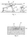
- FIG. 1shows a diagrammatic illustration of a patient bed system comprising a patient bed, a trolley for a bed and a support column for a patient bed,
- FIG. 2shows a partially diagrammatic illustration of the three coupling elements cooperating with one another
- FIG. 3shows a diagrammatic section through the three coupling elements simultaneously in engagement with one another
- FIG. 4shows a partially diagrammatic illustration of a first coupling element alone, which is arranged on a bed-side part
- FIG. 5shows a diagrammatic illustration of the three coupling elements simultaneously in engagement with one another
- FIGS. 6 and 7show in each case an illustration of the three coupling elements during the transfer of the bed from the support column onto the trolley
- FIGS. 8 and 9show in each case illustrations, corresponding to FIG. 6 and 7 , during the transfer of the bed from the trolley onto the support column.
- the patient bed systemillustrated diagrammatically in FIG. 1 , comprises a support column, designated in general by 10 , of an operating table, with a column foot 12 and with a column head 14 mounted vertically adjustably on the latter.
- the height adjustment deviceis not illustrated. It may be designed in any conventional way. As a rule, this may be a hydraulic or mechanical lifting device.
- a trolleyLocated on the left, next to the support column, is a trolley, designated in general by 16 , which carries a bed or table board 18 of the operating table.
- the trolley 16comprises two side frame parts 20 which are connected to one another by means of crosspieces, not illustrated, as is illustrated in EP 457 246 B1.
- the trolley 16can be moved up to the support column 10 such that the latter lies between the side frame parts 20 .
- first coupling elements 22are arranged, which are intended for engagement into second coupling elements 24 on the column head 14 or third coupling elements 26 on the side frame parts 20 of the trolley 16 , in order to connect the bed 18 either to the support column 10 or to the trolley 16 .
- FIG. 228 designates a connecting frame which comprises a middle plate 30 and two side cheeks 32 which project downward at its longitudinal ends and only one of which is illustrated.
- the middle plate 30has on its top side bedding 34 for connection to the actual patient bed 18 which is mounted on the connecting frame 28 pivotably about the bedding axis 36 running transversely with respect to the longitudinal direction of the said patient bed.
- Each of the cheeks 32carries on its inside a first coupling element 22 .
- the latterhas the configuration of a broad tenon with an outer contour 38 , and also a slot-shaped clearance 40 with an inner contour 42 .
- a saddle 44illustrated only partially, which is part of the column head 14 . It is of C-shaped construction, in a similar way to the connecting frame 28 , with a middle web 46 and with two side parts 48 , only one of which is illustrated.
- the side part 48has on its outside a reception pocket, forming the second coupling element 24 , for receiving the first coupling element 22 , the reception pocket having an inner contour 50 adapted to the outer contour 38 of the first coupling element 22 .
- the middle web 46near its respective side part 48 , carries on its top side a centring pin 52 which is intended for engagement into a complementary pin receptacle 54 formed on the underside of the middle plate 30 of the connecting frame 28 .
- FIG. 2there projects into the reception pocket of the second coupling element 24 a guide tenon which forms the third coupling element 26 and which is fastened to the trolley 16 via a pedestal 56 and is intended for engagement into the clearance 40 of the respective first coupling element 22 .
- the said guide tenonhas an outer contour 58 corresponding to the inner contour 42 of the first coupling element 22 .
- FIG. 4shows a diagrammatic top view of the inside of a cheek 32 of the connecting frame 28 .
- the first coupling element 22on which two locking elements 60 and 62 are mounted adjustably, can be seen once again.
- the locking elements 60 and 62are designed in each case in the form of a two-armed lever which is mounted pivotably about a pivot axis 64 or 66 and which is prestressed in each case clockwise by means of a torsion spring 68 or 70 .
- the locking element 60is intended for locking the bed 18 to the column head 14 .
- one lever arm 72is provided with a hooked extension 74 which is intended for engagement into a clearance 76 on the inner contour 50 of the second coupling element 24 ( FIG. 5 ).
- the locking element 62is intended for locking the bed 18 to the trolley 16 .
- the lever arm 78 of the locking element 62has a hooked extension 80 which is intended for engagement into a clearance 82 on the outer contour 58 of the tenon-shaped third coupling element 26 ( FIG. 5 ).
- FIG. 5shows the three coupling elements 22 , 24 and 26 in complete engagement with one another.
- both locking elements 60 and 62are pivoted into their release position.
- thistakes place in that the lever arm 84 opposite to the lever arm 72 slides with control edge 86 on a control cam 88 formed on the third coupling element 26 and is at the same time pivoted anti-clockwise, that end 90 of the first lever arm 72 which is opposite to the hooked extension 74 of the first locking element 60 penetrating into a semicircular clearance 92 in the outer contour of the third coupling element, as shown in FIG. 5 .
- the second locking element 62is pivoted anti-clockwise, in that a lever arm 94 opposite to the lever arm 78 slides with a control edge 96 on a control cam 97 formed on the second coupling element 24 , once again that end 98 of the first lever arm 78 which is opposite to the hooked extension 80 penetrating into a semicircular clearance 100 in the second coupling element 24 , as shown in FIG. 5 .
- FIG. 6shows that, with the commencement of the downward movement of the column head 14 and consequently of the second coupling element 24 , the right-hand locking element 62 is pivoted clockwise under the action of the control cam 97 , sliding on a control edge 101 of the lever end 98 , of the second coupling element 24 , so that the hooked extension 80 is moved into the clearance 82 . Even in the position illustrated in FIG. 6 , the bed 18 could no longer be lifted off from the trolley 16 .
- the column head 14is lowered further, as shown in FIG.
- the hooked extension 80 of the second locking element 62is pivoted completely into the clearance 82 in the third coupling element 26 , so that the bed 18 is locked firmly to the trolley 16 .
- the hooked extension 80is held as a result of the action of the torsion spring 70 .
- the locking element 62would be pivoted anti-clockwise, so that the lock between the first and the third coupling element is cancelled.
- FIG. 8 and 9show the locking operation during the transfer of the bed 18 from the trolley 16 onto the support column 10 .
- the column head 14is raised, so that the third coupling element 26 slides downward out of the clearance 40 of the first coupling element 22 .
- the first locking element 60is positively pivoted clockwise by the control cam 88 sliding on a control edge 103 on the lever end 90 and located on the third coupling element 26 , so that the hooked extension 74 of the first locking element 60 engages into the clearance 76 in the column-side second coupling element 24 , as shown in FIG. 8 .
- both locking elements 60 and 62are pivoted into their release position, if the bed 18 were raised with respect to the column head and the trolley, both locking elements would be pivoted clockwise and consequently be locked. The bed 18 is thus reliably prevented from being lifted out of the position illustrated in FIG. 5 .
- the coupling elements 22 , 24 and 26should lie exactly in alignment with one another. If they are tilted with respect to one another, malfunctions may occur.
- the saddle 44has arranged on it, within the reception pocket of the second coupling element 24 , a sensor, designated in general by 102 , which is intended to sense the position of the third coupling element 26 in relation to the second coupling element 24 .
- the sensorcomprises a rotatably mounted disc 104 which is connected, for example, to a potentiometer tap and on the outside of which is provided an eccentrically arranged sensing finger 106 .
- This sensing finger 106engages into a clearance 108 which is formed on a wide side of the third coupling element 26 and which is delimited by two control edges 110 and 112 . If the transport trolley 16 and the column head 14 are inclined with respect to one another during the take-over operation, so that the coupling elements 24 and 26 are not aligned with one another in the desired form, the sensing finger 106 butts against one of the control edges 110 , 112 . The disc 104 is thereby rotated. This rotation is detected, for example, via the connected potentiometer and can be converted into a control signal which is supplied, in turn, to the control of the column head 14 . The column head 14 can thereby be adjusted such that the second and the third coupling element are aligned with one another, in order to allow friction-free coupling.
Landscapes
- Health & Medical Sciences (AREA)
- Life Sciences & Earth Sciences (AREA)
- Animal Behavior & Ethology (AREA)
- General Health & Medical Sciences (AREA)
- Public Health (AREA)
- Veterinary Medicine (AREA)
- Nursing (AREA)
- Biomedical Technology (AREA)
- Engineering & Computer Science (AREA)
- Invalid Beds And Related Equipment (AREA)
- Accommodation For Nursing Or Treatment Tables (AREA)
- Pharmaceuticals Containing Other Organic And Inorganic Compounds (AREA)
- Orthopedics, Nursing, And Contraception (AREA)
- Electrotherapy Devices (AREA)
- Apparatus For Radiation Diagnosis (AREA)
- Automatic Assembly (AREA)
- Warehouses Or Storage Devices (AREA)
Abstract
Description
Claims (9)
Applications Claiming Priority (4)
| Application Number | Priority Date | Filing Date | Title |
|---|---|---|---|
| DE102005054224 | 2005-11-14 | ||
| DE102005054224.7 | 2005-11-14 | ||
| DE102005054224ADE102005054224A1 (en) | 2005-11-14 | 2005-11-14 | Patient support system |
| DE102005054220.4ADE102005054220B4 (en) | 2005-11-14 | 2005-11-14 | patient support system |
Publications (2)
| Publication Number | Publication Date |
|---|---|
| US20070107124A1 US20070107124A1 (en) | 2007-05-17 |
| US7634826B2true US7634826B2 (en) | 2009-12-22 |
Family
ID=39817102
Family Applications (3)
| Application Number | Title | Priority Date | Filing Date |
|---|---|---|---|
| US11/598,527ActiveUS7634826B2 (en) | 2005-11-14 | 2006-11-13 | Patient bed system |
| US11/598,526ActiveUS7526823B2 (en) | 2005-11-14 | 2006-11-13 | Patient bed system |
| US12/355,334ActiveUS7757316B2 (en) | 2005-11-14 | 2009-01-16 | Patient bed system |
Family Applications After (2)
| Application Number | Title | Priority Date | Filing Date |
|---|---|---|---|
| US11/598,526ActiveUS7526823B2 (en) | 2005-11-14 | 2006-11-13 | Patient bed system |
| US12/355,334ActiveUS7757316B2 (en) | 2005-11-14 | 2009-01-16 | Patient bed system |
Country Status (13)
| Country | Link |
|---|---|
| US (3) | US7634826B2 (en) |
| EP (2) | EP1785115B1 (en) |
| JP (2) | JP4866212B2 (en) |
| KR (2) | KR101269279B1 (en) |
| CN (2) | CN1973798B (en) |
| AT (2) | ATE454876T1 (en) |
| BR (2) | BRPI0604749B8 (en) |
| CA (2) | CA2567876A1 (en) |
| DE (4) | DE102005054224A1 (en) |
| DK (1) | DK1785116T3 (en) |
| ES (2) | ES2338250T3 (en) |
| PL (2) | PL1785115T3 (en) |
| RU (2) | RU2340322C2 (en) |
Cited By (12)
| Publication number | Priority date | Publication date | Assignee | Title |
|---|---|---|---|---|
| US20070101497A1 (en)* | 2005-11-10 | 2007-05-10 | Maquet Gmbh & Co. Kg | Hydraulic column clamping |
| US20070107125A1 (en)* | 2005-11-14 | 2007-05-17 | Maquet Gmbh & Co. Kg | Operating table |
| US20070107129A1 (en)* | 2005-11-14 | 2007-05-17 | Maquet Gmbh & Co. Kg | Patient bed for an operating table |
| US20080306369A1 (en)* | 2007-06-06 | 2008-12-11 | General Electric Company | Detachable latching mechanism |
| US20090119842A1 (en)* | 2005-11-14 | 2009-05-14 | Maquet Gmbh & Co. Kg | Patient bed system |
| US7896569B2 (en) | 2005-11-14 | 2011-03-01 | Maquet Gmbh & Co. Kg | Joint arrangement for the connection of two segments of a patient bed |
| US8249457B2 (en) | 2005-11-14 | 2012-08-21 | Maquet Gmbh & Co. Kg | Method and device for bidirectional IR data transfer between a medical treatment table and an operator control device |
| US20140130259A1 (en)* | 2012-11-09 | 2014-05-15 | MAQUET GmbH | Transport carriage for transport of a patient support and/or an operating table column of an operating table |
| US8978207B2 (en) | 2013-03-15 | 2015-03-17 | Electrolux Home Care Products, Inc. | Vacuum cleaner edge cleaning system |
| US9993378B2 (en) | 2014-02-11 | 2018-06-12 | Medline Industries, Inc. | Method and apparatus for a locking caster |
| US10002529B2 (en)* | 2013-06-06 | 2018-06-19 | MAQUET GmbH | Operating table system |
| US11229563B2 (en) | 2014-08-27 | 2022-01-25 | Umano Medical Inc. | Support panel pivoting system for a patient support device |
Families Citing this family (15)
| Publication number | Priority date | Publication date | Assignee | Title |
|---|---|---|---|---|
| DE102005053754A1 (en)* | 2005-11-10 | 2007-05-16 | Maquet Gmbh & Co Kg | Device for adjusting the lying surface of a surgical table |
| DE102005053755A1 (en) | 2005-11-10 | 2007-05-16 | Maquet Gmbh & Co Kg | Upholstery element for a patient support surface of a surgical table |
| DE102005054223A1 (en)* | 2005-11-14 | 2007-05-16 | Maquet Gmbh & Co Kg | Device for adjusting an operating table |
| DE102005054221A1 (en)* | 2005-11-14 | 2007-05-16 | Maquet Gmbh & Co Kg | Patient support system |
| WO2007067874A2 (en)* | 2005-12-05 | 2007-06-14 | Ahlman Scott M | Patient single surface system |
| DE502007007063D1 (en) | 2007-08-03 | 2011-06-09 | Trumpf Medizin Systeme Gmbh & Co Kg | operating table |
| DE102009053966A1 (en)* | 2009-11-19 | 2011-05-26 | Maquet Gmbh & Co. Kg | Arrangement and method for connecting an accessory to an operating table |
| US9107792B2 (en) | 2012-09-07 | 2015-08-18 | Allen Medical Systems, Inc. | Carriage for a surgical boot of a hip distractor |
| US9730851B2 (en) | 2012-09-07 | 2017-08-15 | Allen Medical Systems, Inc. | Surgical support system |
| DE102013103757B4 (en)* | 2013-04-15 | 2017-06-29 | MAQUET GmbH | Method and device for operating a mobile operating table |
| DE102014211269A1 (en)* | 2014-03-25 | 2015-10-01 | Siemens Aktiengesellschaft | Medical examination device |
| US10835430B2 (en)* | 2016-09-02 | 2020-11-17 | Stryker Corporation | Patient mobility system with integrated ambulation device |
| DE102016216996A1 (en)* | 2016-09-07 | 2018-03-08 | Trumpf Medizin Systeme Gmbh + Co. Kg | Connection device and method for unlocking the connection device |
| CN109381216B (en)* | 2017-08-08 | 2023-08-01 | 通用电气公司 | Motion control device and method for patient moving bed board and computer program |
| DE102018129370A1 (en) | 2018-11-21 | 2020-05-28 | ReActive Robotics GmbH | Device and method for reversibly connecting a rehabilitation mechanism to a bed, and method for operating a rehabilitation mechanism connected to a bed |
Citations (81)
| Publication number | Priority date | Publication date | Assignee | Title |
|---|---|---|---|---|
| DE264297C (en) | ||||
| US566521A (en) | 1896-08-25 | Show-fixture | ||
| US1740906A (en) | 1925-06-17 | 1929-12-24 | Rothauszky Simon | Adjustable sectional bed |
| US2416410A (en) | 1943-02-22 | 1947-02-25 | Leah Ree Shampaine | Operating and examining table |
| US2763320A (en) | 1952-04-04 | 1956-09-18 | Arthur I Schram | Furniture article with lifting jack |
| US2764459A (en) | 1953-01-19 | 1956-09-25 | Ritter Co Inc | Hydraulic tip type medical examination and operating tables |
| US2771330A (en) | 1953-07-08 | 1956-11-20 | Smit Rontgen N V | Tilting mechanism for x-ray examination table |
| US2775496A (en) | 1953-05-13 | 1956-12-25 | Hartford Nat Bank & Trust Co | Tilting x-ray medical examination table |
| US2816806A (en) | 1953-07-08 | 1957-12-17 | Smit Routgen N V | Tilting mechanism for x-ray examination table |
| US2995762A (en)* | 1960-01-18 | 1961-08-15 | Miller Herman Inc | Appointments for beds |
| US3226734A (en) | 1963-09-30 | 1966-01-04 | Orange M Welborn M D | Device for supporting hospital patients and for the support of articles for transportation |
| US3238539A (en) | 1962-09-05 | 1966-03-08 | Koch Albert | Rotatable beds for invalids |
| US3302218A (en) | 1965-05-28 | 1967-02-07 | Stryker Corp | Turning frame |
| US3328079A (en) | 1965-11-24 | 1967-06-27 | Young Spring & Wire Corp | Reclining seat |
| US3379877A (en) | 1964-04-24 | 1968-04-23 | Tokyo Shibaura Electric Co | Tiltable table for radiofluoroscopic apparatus |
| US3388700A (en) | 1964-08-27 | 1968-06-18 | Mountz Forrest Kindle | Means and process for effecting periodic body inversion |
| GB1321193A (en) | 1971-03-03 | 1973-06-20 | Universal Oil Prod Co | Seats |
| US3868103A (en) | 1973-04-24 | 1975-02-25 | Millet Roux & Cie Ltee | Surgical and examination table structure |
| US4101120A (en) | 1976-08-10 | 1978-07-18 | Mizuho Ika Kogyo Kabushiki Kaisha | Electrically driven, separate type, surgical operation table |
| FR2388546A1 (en) | 1977-04-30 | 1978-11-24 | Emda | Slewing dentists chair base - has retaining washer acting against rotary disc via flat strips of rearing material e.g. PTFE |
| US4176415A (en) | 1978-03-31 | 1979-12-04 | Dickerson Evelyn C | Lounge with articulated side-by-side independently adjustable longitudinal sections |
| US4244358A (en) | 1979-09-10 | 1981-01-13 | Noel Pyers | Rollover bed having pallet with flex points and constant traction maintaining apparatus |
| US4597119A (en) | 1984-12-17 | 1986-07-01 | Edwin Padgett | Suntanning device |
| US4640482A (en) | 1984-09-25 | 1987-02-03 | Polaroid Corporation | Foldable tripod |
| US5031547A (en) | 1988-03-24 | 1991-07-16 | Hihaisuto Seiko Kabushiki Kaisha | Mechanism for moving a table lengthwise and crosswise and for turning the table |
| EP0457246A1 (en) | 1990-05-14 | 1991-11-21 | Stierlen-Maquet Aktiengesellschaft | Mobile patient support system |
| GB2260075A (en) | 1991-10-05 | 1993-04-07 | Smiths Industries Plc | Patient support table. |
| US5220698A (en) | 1991-10-05 | 1993-06-22 | Smiths Industries Public Limited Company | Patient support tables |
| DE4229318C1 (en) | 1992-09-02 | 1993-09-23 | Siemens Ag, 80333 Muenchen, De | Patient-positioning device with table pivotable about fixed axis - incorporates system of parallelogram-forming levers and linkages rotatable about axes by two electromechanical drives |
| US5279011A (en) | 1991-11-21 | 1994-01-18 | Stierlen-Maquet Ag | Operation table with removably mounted patient support surface means |
| GB2277870A (en) | 1993-05-15 | 1994-11-16 | Smiths Industries Plc | Patient transfer trolley |
| US5544376A (en) | 1994-01-31 | 1996-08-13 | Maxwell Products, Inc. | Articulated bed with customizable remote control |
| DE29610726U1 (en) | 1996-06-19 | 1996-09-05 | Schmitz u. Söhne GmbH & Co KG, 58739 Wickede | Mobile patient support system |
| US5564852A (en) | 1995-03-29 | 1996-10-15 | Burndy Corporation | Adjustable hot stick adaptor |
| US5611638A (en)* | 1994-07-04 | 1997-03-18 | Stierlen-Maquet Ag | Connecting device for selectively connecting a patient support means with the support column of an operating table |
| US5615431A (en) | 1995-04-06 | 1997-04-01 | Givas Habitat S.R.L. | Bed framework which is adjustable in elevation |
| US5621932A (en)* | 1994-08-20 | 1997-04-22 | Smiths Industries Public Limited | Patient support systems |
| US5649833A (en) | 1994-07-04 | 1997-07-22 | Maquet Ag | Connecting module |
| US5651150A (en)* | 1995-04-18 | 1997-07-29 | Maquet Ag | Mobile patient support system |
| US5659909A (en) | 1994-07-04 | 1997-08-26 | Maquet Ag | Operating table patient support means |
| EP0832603A1 (en) | 1996-09-27 | 1998-04-01 | Siemens-Elema AB | Examination table |
| US5754997A (en) | 1994-08-15 | 1998-05-26 | Midmark Corporation | Support cushion for surgery table |
| US5787528A (en) | 1995-10-04 | 1998-08-04 | Antinori; Santino | Method and apparatus for providing bed recall functions |
| DE19732467A1 (en) | 1997-07-28 | 1999-02-04 | Siemens Ag | Hospital trolley and table system for patients |
| EP0913139A1 (en) | 1997-11-03 | 1999-05-06 | BLANCO MED GmbH | Modular operating table system |
| DE19751320A1 (en) | 1997-11-19 | 1999-05-20 | Blanco Med Gmbh | Control unit for controlling an operating table top |
| WO1999028146A1 (en) | 1997-11-27 | 1999-06-10 | Carlgrens Ergonomi Ab | Transversally displaceable and rotatable seat column |
| US6008598A (en) | 1998-04-22 | 1999-12-28 | Patmark Company, Inc. | Hand-held controller for bed and mattress assembly |
| US6073284A (en) | 1997-11-07 | 2000-06-13 | Hill-Rom, Inc. | Surgical table |
| US6095713A (en) | 1992-06-24 | 2000-08-01 | D & D Group Pty Ltd | Engagement device and coupling member |
| DE19919496A1 (en) | 1999-04-29 | 2000-11-02 | Blanco Med Gmbh | Operating table system; has support column that can be used to adjust operating table plate and control device to limit adjustment of table plate according to characteristics of support column |
| US6351678B1 (en) | 1997-11-07 | 2002-02-26 | Hill-Rom Services, Inc. | Medical equipment controller |
| US6390927B1 (en) | 1999-10-22 | 2002-05-21 | Cleveland Tool Corporation | Spring loaded U-joint with spring retaining surface |
| WO2002055001A1 (en) | 2001-01-13 | 2002-07-18 | Eschmann Holdings Limited | Surgical tables |
| US20020170115A1 (en) | 1997-11-07 | 2002-11-21 | Borders Richard L. | Leg section support for a surgical table |
| US6484334B1 (en) | 1997-11-07 | 2002-11-26 | Hill-Rom Services, Inc. | Surgical table |
| US20030078144A1 (en) | 2001-10-19 | 2003-04-24 | Gehrke Jon C. | Leg elevator system |
| US6565156B1 (en) | 1999-02-03 | 2003-05-20 | Koyo Giken Co., Ltd. | Angle adjusting device |
| US6609260B2 (en) | 2000-03-17 | 2003-08-26 | Hill-Rom Services, Inc. | Proning bed and method of operating the same |
| US6619872B2 (en) | 1999-12-13 | 2003-09-16 | Norgren Automotive, Inc. | Modular tooling coupling apparatus |
| US20030195644A1 (en) | 1997-11-07 | 2003-10-16 | Borders Richard L. | Medical equipment controller |
| WO2003086263A1 (en) | 2002-04-05 | 2003-10-23 | Eschmann Holdings Limited | Surgical table transfer system |
| US6722289B2 (en) | 2001-05-16 | 2004-04-20 | Nippon Thompson Co., Ltd. | Table system with angular position controls |
| DE10253878A1 (en) | 2002-11-12 | 2004-05-27 | Trumpf Medizin Systeme Gmbh | Operating table has support column and table plate that move relative to each other, to at least two positions by use of interacting electricity and data transfer modules, each with at least two interacting transfer elements |
| DE10253906A1 (en) | 2002-11-19 | 2004-06-03 | Maquet Gmbh & Co. Kg | Leg plate arrangement for operating tables |
| US20040172757A1 (en) | 2002-11-26 | 2004-09-09 | Baskar Somasundaram | Multiconfiguration braking system |
| US6986179B2 (en) | 2002-11-26 | 2006-01-17 | Ge Medical Systems Global Technology Company, Llc | Grouted tilting patient positioning table for vascular applications |
| US7068143B2 (en) | 2001-11-20 | 2006-06-27 | Trumpf Medizin Systeme Gmbh | Method and apparatus for the remote control of an operating table |
| US7089612B2 (en) | 2001-01-09 | 2006-08-15 | Fhsurgical | Motorized operating table with multiple sections |
| US20070107123A1 (en) | 2005-11-14 | 2007-05-17 | Maquet Gmbh & Co. Kg | Patient bed system |
| US20070110448A1 (en) | 2005-11-14 | 2007-05-17 | Jurgen Ruch | Method and device for bidirectional IR data transfer between a medical treatment table and an operator control device |
| US20070107129A1 (en) | 2005-11-14 | 2007-05-17 | Maquet Gmbh & Co. Kg | Patient bed for an operating table |
| US20070107125A1 (en) | 2005-11-14 | 2007-05-17 | Maquet Gmbh & Co. Kg | Operating table |
| US20070107126A1 (en) | 2005-11-14 | 2007-05-17 | Maquet Gmbh & Co. Kg | Device for adjusting an operating table |
| US20070116512A1 (en) | 2005-11-14 | 2007-05-24 | Maquet Gmbh & Co. Kg | Joint arrangement for the connection of two segments of a patient bed |
| US20070118989A1 (en) | 2005-11-14 | 2007-05-31 | Maquet Gmbh & Co. Kg | Patient bed system |
| US7235942B2 (en) | 2002-03-18 | 2007-06-26 | Paramount Bed Co, Ltd. | Method of controlling the lifting of bottom sections of lying furniture such as a bed |
| US7321811B1 (en) | 2006-09-14 | 2008-01-22 | Rawls-Meehan Martin B | Methods and systems of adjustable bed position control |
| US7346944B2 (en) | 2004-11-05 | 2008-03-25 | Mark Shaw | Mattress monitoring system |
| US7367740B2 (en) | 2003-04-10 | 2008-05-06 | Pedrag Lazic | Mechanically lockable universal joint and structures employing such joint |
| US7398790B2 (en) | 2003-08-22 | 2008-07-15 | Glatz Ag | Extension arm for a free arm parasol, pivotably arranged on a carrier |
Family Cites Families (26)
| Publication number | Priority date | Publication date | Assignee | Title |
|---|---|---|---|---|
| DE457246C (en)* | 1928-03-12 | Carl Eilers | Spring-loaded bicycle frame | |
| DE1196815B (en) | 1964-03-21 | 1965-07-15 | Stierlen Werke Ag | Operating table with fixed lower part and transportable bed |
| US3886606A (en)* | 1973-05-29 | 1975-06-03 | John Guythar Bradford | Foldable casualty carrier |
| SU1393421A1 (en)* | 1985-04-08 | 1988-05-07 | Г.П.Потёхин | Arrangement for preventing decubitus |
| SU1531975A1 (en)* | 1986-11-19 | 1989-12-30 | П.И.Блинчиков | Support member |
| US4768241A (en) | 1987-02-24 | 1988-09-06 | Beney Daniel R | Self contained, mobile intensive care bed structure |
| US5277427A (en) | 1992-05-27 | 1994-01-11 | Bryan Robert M | Golf training club |
| US5396672A (en)* | 1993-10-18 | 1995-03-14 | Brown; Timothy E. | Combination surgical table and protective cover and method therefor |
| US5647799A (en) | 1995-06-15 | 1997-07-15 | Dana Corporation | Bearing cap for universal joint having anti-rotation protrusions |
| FI955200A7 (en) | 1995-10-31 | 1997-05-01 | Nokia Corp | Common protocol for half-duplex traffic |
| ATE208246T1 (en) | 1998-10-02 | 2001-11-15 | Oetiker Hans Maschinen | DEVICE FOR ARRANGING, TENSIONING OR SHRINKING A RING-SHAPED RETENTION ORGANIC |
| SG87784A1 (en) | 1998-12-09 | 2002-04-16 | Kent Ridge Digital Labs | Csma/cd wireless lan |
| JP2001129021A (en) | 1999-11-08 | 2001-05-15 | Mizuho Co Ltd | Stretcher |
| US6584630B1 (en)* | 2000-04-06 | 2003-07-01 | Ohio Medical Instrument Company, Inc. | Radiolucent surgical table extension assembly and method |
| EP1290652A2 (en) | 2000-05-05 | 2003-03-12 | Hill-Rom Services, Inc. | Hospital monitoring and control system and method |
| US6499158B1 (en)* | 2000-10-30 | 2002-12-31 | Steris, Inc. | Surgical table top and accessory clamp used thereon |
| RU2212873C2 (en)* | 2000-11-01 | 2003-09-27 | Зао "Техкомплект" | Traumatologic table wheel litter |
| DE10057304A1 (en) | 2000-11-17 | 2002-05-23 | Putzmeister Ag | Pipe coupling comprises two shells around circular opening for pipe, external link, support block, closure mechanism, closure hook and swivel axle. |
| AU2002326417A1 (en) | 2001-07-20 | 2003-03-03 | Hill-Rom Services, Inc. | Badge for a locating and tracking system |
| US7154397B2 (en) | 2001-08-03 | 2006-12-26 | Hill Rom Services, Inc. | Patient point-of-care computer system |
| US7104201B2 (en)* | 2001-09-25 | 2006-09-12 | Clear Solutions, Inc. | Sterile surgical table cover |
| JP3892268B2 (en)* | 2001-10-17 | 2007-03-14 | タカラベルモント株式会社 | Detachable mechanism of remote operating table |
| EP1381057B1 (en)* | 2002-07-10 | 2008-12-03 | STMicroelectronics S.r.l. | Line selector for a matrix of memory elements |
| US7412736B2 (en) | 2005-09-13 | 2008-08-19 | Midmark Corporation | Conjoined electrical cords for an examination table |
| DE102005053753A1 (en)* | 2005-11-10 | 2007-05-16 | Maquet Gmbh & Co Kg | Hydraulic column clamping |
| DE102005053754A1 (en)* | 2005-11-10 | 2007-05-16 | Maquet Gmbh & Co Kg | Device for adjusting the lying surface of a surgical table |
- 2005
- 2005-11-14DEDE102005054224Apatent/DE102005054224A1/ennot_activeWithdrawn
- 2005-11-14DEDE102005054220.4Apatent/DE102005054220B4/enactiveActive
- 2006
- 2006-11-07ATAT06123599Tpatent/ATE454876T1/enactive
- 2006-11-07DEDE502006005902Tpatent/DE502006005902D1/enactiveActive
- 2006-11-07ESES06123599Tpatent/ES2338250T3/enactiveActive
- 2006-11-07PLPL06123599Tpatent/PL1785115T3/enunknown
- 2006-11-07EPEP06123599Apatent/EP1785115B1/enactiveActive
- 2006-11-09DEDE502006001184Tpatent/DE502006001184D1/ennot_activeExpired - Fee Related
- 2006-11-09ATAT06123719Tpatent/ATE401852T1/ennot_activeIP Right Cessation
- 2006-11-09PLPL06123719Tpatent/PL1785116T3/enunknown
- 2006-11-09EPEP06123719Apatent/EP1785116B1/enactiveActive
- 2006-11-09ESES06123719Tpatent/ES2308676T3/enactiveActive
- 2006-11-09DKDK06123719Tpatent/DK1785116T3/enactive
- 2006-11-10CACA002567876Apatent/CA2567876A1/ennot_activeAbandoned
- 2006-11-10CACA002568040Apatent/CA2568040A1/ennot_activeAbandoned
- 2006-11-13RURU2006139971/14Apatent/RU2340322C2/ennot_activeIP Right Cessation
- 2006-11-13USUS11/598,527patent/US7634826B2/enactiveActive
- 2006-11-13USUS11/598,526patent/US7526823B2/enactiveActive
- 2006-11-13RURU2006139974/14Apatent/RU2407501C2/ennot_activeIP Right Cessation
- 2006-11-13JPJP2006306554Apatent/JP4866212B2/enactiveActive
- 2006-11-13JPJP2006306553Apatent/JP4917865B2/enactiveActive
- 2006-11-14KRKR1020060112250Apatent/KR101269279B1/ennot_activeExpired - Fee Related
- 2006-11-14CNCN2006101446636Apatent/CN1973798B/enactiveActive
- 2006-11-14KRKR1020060112249Apatent/KR101213320B1/ennot_activeExpired - Fee Related
- 2006-11-14BRBRPI0604749Apatent/BRPI0604749B8/ennot_activeIP Right Cessation
- 2006-11-14BRBRPI0604751Apatent/BRPI0604751B8/ennot_activeIP Right Cessation
- 2006-11-14CNCN2006101446640Apatent/CN1969788B/enactiveActive
- 2009
- 2009-01-16USUS12/355,334patent/US7757316B2/enactiveActive
Patent Citations (98)
| Publication number | Priority date | Publication date | Assignee | Title |
|---|---|---|---|---|
| US566521A (en) | 1896-08-25 | Show-fixture | ||
| DE264297C (en) | ||||
| US1740906A (en) | 1925-06-17 | 1929-12-24 | Rothauszky Simon | Adjustable sectional bed |
| US2416410A (en) | 1943-02-22 | 1947-02-25 | Leah Ree Shampaine | Operating and examining table |
| US2763320A (en) | 1952-04-04 | 1956-09-18 | Arthur I Schram | Furniture article with lifting jack |
| US2764459A (en) | 1953-01-19 | 1956-09-25 | Ritter Co Inc | Hydraulic tip type medical examination and operating tables |
| US2775496A (en) | 1953-05-13 | 1956-12-25 | Hartford Nat Bank & Trust Co | Tilting x-ray medical examination table |
| US2771330A (en) | 1953-07-08 | 1956-11-20 | Smit Rontgen N V | Tilting mechanism for x-ray examination table |
| US2816806A (en) | 1953-07-08 | 1957-12-17 | Smit Routgen N V | Tilting mechanism for x-ray examination table |
| US2995762A (en)* | 1960-01-18 | 1961-08-15 | Miller Herman Inc | Appointments for beds |
| US3238539A (en) | 1962-09-05 | 1966-03-08 | Koch Albert | Rotatable beds for invalids |
| US3226734A (en) | 1963-09-30 | 1966-01-04 | Orange M Welborn M D | Device for supporting hospital patients and for the support of articles for transportation |
| US3379877A (en) | 1964-04-24 | 1968-04-23 | Tokyo Shibaura Electric Co | Tiltable table for radiofluoroscopic apparatus |
| US3388700A (en) | 1964-08-27 | 1968-06-18 | Mountz Forrest Kindle | Means and process for effecting periodic body inversion |
| US3302218A (en) | 1965-05-28 | 1967-02-07 | Stryker Corp | Turning frame |
| US3328079A (en) | 1965-11-24 | 1967-06-27 | Young Spring & Wire Corp | Reclining seat |
| GB1321193A (en) | 1971-03-03 | 1973-06-20 | Universal Oil Prod Co | Seats |
| US3868103A (en) | 1973-04-24 | 1975-02-25 | Millet Roux & Cie Ltee | Surgical and examination table structure |
| US4101120A (en) | 1976-08-10 | 1978-07-18 | Mizuho Ika Kogyo Kabushiki Kaisha | Electrically driven, separate type, surgical operation table |
| FR2388546A1 (en) | 1977-04-30 | 1978-11-24 | Emda | Slewing dentists chair base - has retaining washer acting against rotary disc via flat strips of rearing material e.g. PTFE |
| US4176415A (en) | 1978-03-31 | 1979-12-04 | Dickerson Evelyn C | Lounge with articulated side-by-side independently adjustable longitudinal sections |
| US4244358A (en) | 1979-09-10 | 1981-01-13 | Noel Pyers | Rollover bed having pallet with flex points and constant traction maintaining apparatus |
| US4640482A (en) | 1984-09-25 | 1987-02-03 | Polaroid Corporation | Foldable tripod |
| US4597119A (en) | 1984-12-17 | 1986-07-01 | Edwin Padgett | Suntanning device |
| US5031547A (en) | 1988-03-24 | 1991-07-16 | Hihaisuto Seiko Kabushiki Kaisha | Mechanism for moving a table lengthwise and crosswise and for turning the table |
| EP0457246A1 (en) | 1990-05-14 | 1991-11-21 | Stierlen-Maquet Aktiengesellschaft | Mobile patient support system |
| US5083331A (en) | 1990-05-14 | 1992-01-28 | Stierlen-Maquet Ag | Mobile patient support system |
| GB2260075A (en) | 1991-10-05 | 1993-04-07 | Smiths Industries Plc | Patient support table. |
| US5220698A (en) | 1991-10-05 | 1993-06-22 | Smiths Industries Public Limited Company | Patient support tables |
| US5279011A (en) | 1991-11-21 | 1994-01-18 | Stierlen-Maquet Ag | Operation table with removably mounted patient support surface means |
| US6095713A (en) | 1992-06-24 | 2000-08-01 | D & D Group Pty Ltd | Engagement device and coupling member |
| DE4229318C1 (en) | 1992-09-02 | 1993-09-23 | Siemens Ag, 80333 Muenchen, De | Patient-positioning device with table pivotable about fixed axis - incorporates system of parallelogram-forming levers and linkages rotatable about axes by two electromechanical drives |
| GB2277870A (en) | 1993-05-15 | 1994-11-16 | Smiths Industries Plc | Patient transfer trolley |
| EP0625348A1 (en) | 1993-05-15 | 1994-11-23 | Smiths Industries Public Limited Company | Operating tables, trolleys and transfer systems |
| US5477570A (en)* | 1993-05-15 | 1995-12-26 | Smiths Industries Public Limited Company | Operating tables, trolleys and transfer systems |
| US5544376A (en) | 1994-01-31 | 1996-08-13 | Maxwell Products, Inc. | Articulated bed with customizable remote control |
| US5969488A (en) | 1994-01-31 | 1999-10-19 | Maxwell Products, Inc. | Remotely-controllable bed system |
| US5611638A (en)* | 1994-07-04 | 1997-03-18 | Stierlen-Maquet Ag | Connecting device for selectively connecting a patient support means with the support column of an operating table |
| US5649833A (en) | 1994-07-04 | 1997-07-22 | Maquet Ag | Connecting module |
| US5659909A (en) | 1994-07-04 | 1997-08-26 | Maquet Ag | Operating table patient support means |
| US5754997A (en) | 1994-08-15 | 1998-05-26 | Midmark Corporation | Support cushion for surgery table |
| US5621932A (en)* | 1994-08-20 | 1997-04-22 | Smiths Industries Public Limited | Patient support systems |
| US5564852A (en) | 1995-03-29 | 1996-10-15 | Burndy Corporation | Adjustable hot stick adaptor |
| US5615431A (en) | 1995-04-06 | 1997-04-01 | Givas Habitat S.R.L. | Bed framework which is adjustable in elevation |
| US5651150A (en)* | 1995-04-18 | 1997-07-29 | Maquet Ag | Mobile patient support system |
| US5787528A (en) | 1995-10-04 | 1998-08-04 | Antinori; Santino | Method and apparatus for providing bed recall functions |
| DE29610726U1 (en) | 1996-06-19 | 1996-09-05 | Schmitz u. Söhne GmbH & Co KG, 58739 Wickede | Mobile patient support system |
| EP0832603A1 (en) | 1996-09-27 | 1998-04-01 | Siemens-Elema AB | Examination table |
| US5790996A (en) | 1996-09-27 | 1998-08-11 | Siemens-Elma Ab | Examination table for supporting and positioning a patient in a medical examination apparatus |
| DE19732467A1 (en) | 1997-07-28 | 1999-02-04 | Siemens Ag | Hospital trolley and table system for patients |
| EP0913139A1 (en) | 1997-11-03 | 1999-05-06 | BLANCO MED GmbH | Modular operating table system |
| US6560492B2 (en) | 1997-11-07 | 2003-05-06 | Hill-Rom Services, Inc. | Medical equipment controller |
| US6073284A (en) | 1997-11-07 | 2000-06-13 | Hill-Rom, Inc. | Surgical table |
| US7010369B2 (en) | 1997-11-07 | 2006-03-07 | Hill-Rom Services, Inc. | Medical equipment controller |
| US6351678B1 (en) | 1997-11-07 | 2002-02-26 | Hill-Rom Services, Inc. | Medical equipment controller |
| US20030195644A1 (en) | 1997-11-07 | 2003-10-16 | Borders Richard L. | Medical equipment controller |
| US20020111701A1 (en) | 1997-11-07 | 2002-08-15 | Hill-Rom Services, Inc. | Medical equipment controller |
| US20020170115A1 (en) | 1997-11-07 | 2002-11-21 | Borders Richard L. | Leg section support for a surgical table |
| US6484334B1 (en) | 1997-11-07 | 2002-11-26 | Hill-Rom Services, Inc. | Surgical table |
| DE19751320A1 (en) | 1997-11-19 | 1999-05-20 | Blanco Med Gmbh | Control unit for controlling an operating table top |
| WO1999028146A1 (en) | 1997-11-27 | 1999-06-10 | Carlgrens Ergonomi Ab | Transversally displaceable and rotatable seat column |
| US6008598A (en) | 1998-04-22 | 1999-12-28 | Patmark Company, Inc. | Hand-held controller for bed and mattress assembly |
| US6396224B1 (en) | 1998-04-22 | 2002-05-28 | Hill-Rom Services, Inc. | Hand-held controller for bed and mattress assembly |
| US6565156B1 (en) | 1999-02-03 | 2003-05-20 | Koyo Giken Co., Ltd. | Angle adjusting device |
| DE19919496A1 (en) | 1999-04-29 | 2000-11-02 | Blanco Med Gmbh | Operating table system; has support column that can be used to adjust operating table plate and control device to limit adjustment of table plate according to characteristics of support column |
| US6390927B1 (en) | 1999-10-22 | 2002-05-21 | Cleveland Tool Corporation | Spring loaded U-joint with spring retaining surface |
| US6619872B2 (en) | 1999-12-13 | 2003-09-16 | Norgren Automotive, Inc. | Modular tooling coupling apparatus |
| US6609260B2 (en) | 2000-03-17 | 2003-08-26 | Hill-Rom Services, Inc. | Proning bed and method of operating the same |
| US6862761B2 (en) | 2000-03-17 | 2005-03-08 | Hill-Rom Services, Inc. | Hospital proning bed |
| US20040006821A1 (en) | 2000-03-17 | 2004-01-15 | Hill-Rom Services, Inc. | Hospital bed |
| US7089612B2 (en) | 2001-01-09 | 2006-08-15 | Fhsurgical | Motorized operating table with multiple sections |
| WO2002055001A1 (en) | 2001-01-13 | 2002-07-18 | Eschmann Holdings Limited | Surgical tables |
| US20040074003A1 (en) | 2001-01-13 | 2004-04-22 | Bannister Grahame David | Surgical tables |
| US6971131B2 (en) | 2001-01-13 | 2005-12-06 | Eschmann Holdings Limited | Surgical tables |
| US6722289B2 (en) | 2001-05-16 | 2004-04-20 | Nippon Thompson Co., Ltd. | Table system with angular position controls |
| US20030078144A1 (en) | 2001-10-19 | 2003-04-24 | Gehrke Jon C. | Leg elevator system |
| US7068143B2 (en) | 2001-11-20 | 2006-06-27 | Trumpf Medizin Systeme Gmbh | Method and apparatus for the remote control of an operating table |
| US7235942B2 (en) | 2002-03-18 | 2007-06-26 | Paramount Bed Co, Ltd. | Method of controlling the lifting of bottom sections of lying furniture such as a bed |
| US7181791B2 (en)* | 2002-04-05 | 2007-02-27 | Eschmann Holdings Limited | Surgical table transfer system |
| WO2003086263A1 (en) | 2002-04-05 | 2003-10-23 | Eschmann Holdings Limited | Surgical table transfer system |
| DE10253878A1 (en) | 2002-11-12 | 2004-05-27 | Trumpf Medizin Systeme Gmbh | Operating table has support column and table plate that move relative to each other, to at least two positions by use of interacting electricity and data transfer modules, each with at least two interacting transfer elements |
| DE10253906A1 (en) | 2002-11-19 | 2004-06-03 | Maquet Gmbh & Co. Kg | Leg plate arrangement for operating tables |
| US20040172757A1 (en) | 2002-11-26 | 2004-09-09 | Baskar Somasundaram | Multiconfiguration braking system |
| US6986179B2 (en) | 2002-11-26 | 2006-01-17 | Ge Medical Systems Global Technology Company, Llc | Grouted tilting patient positioning table for vascular applications |
| US7367740B2 (en) | 2003-04-10 | 2008-05-06 | Pedrag Lazic | Mechanically lockable universal joint and structures employing such joint |
| US7398790B2 (en) | 2003-08-22 | 2008-07-15 | Glatz Ag | Extension arm for a free arm parasol, pivotably arranged on a carrier |
| US7346944B2 (en) | 2004-11-05 | 2008-03-25 | Mark Shaw | Mattress monitoring system |
| US20070107129A1 (en) | 2005-11-14 | 2007-05-17 | Maquet Gmbh & Co. Kg | Patient bed for an operating table |
| US20070107126A1 (en) | 2005-11-14 | 2007-05-17 | Maquet Gmbh & Co. Kg | Device for adjusting an operating table |
| US20070116512A1 (en) | 2005-11-14 | 2007-05-24 | Maquet Gmbh & Co. Kg | Joint arrangement for the connection of two segments of a patient bed |
| US20070118989A1 (en) | 2005-11-14 | 2007-05-31 | Maquet Gmbh & Co. Kg | Patient bed system |
| US20070107124A1 (en)* | 2005-11-14 | 2007-05-17 | Maquet Gmbh & Co. Kg | Patient bed system |
| US20070107125A1 (en) | 2005-11-14 | 2007-05-17 | Maquet Gmbh & Co. Kg | Operating table |
| US20070110448A1 (en) | 2005-11-14 | 2007-05-17 | Jurgen Ruch | Method and device for bidirectional IR data transfer between a medical treatment table and an operator control device |
| US20070107123A1 (en) | 2005-11-14 | 2007-05-17 | Maquet Gmbh & Co. Kg | Patient bed system |
| US7526823B2 (en)* | 2005-11-14 | 2009-05-05 | Maquet Gmbh & Co. Kg | Patient bed system |
| US20090119842A1 (en)* | 2005-11-14 | 2009-05-14 | Maquet Gmbh & Co. Kg | Patient bed system |
| US7321811B1 (en) | 2006-09-14 | 2008-01-22 | Rawls-Meehan Martin B | Methods and systems of adjustable bed position control |
Non-Patent Citations (8)
| Title |
|---|
| European Search Report for Application No. EP 06 12 3444, dated Aug. 22, 2008. |
| European Search Report for Application No. EP 06 12 3721, dated Jun. 20, 2008. |
| European Search Report for Serial No. EP 06 12 3443 dated Feb. 7, 2007. |
| European Search Report for Serial No. EP 06 12 3592 dated Nov. 29, 2007. |
| European Search Report for Serial No. EP 06 12 3593 dated Dec. 4, 2007. |
| European Search Report for Serial No. EP 06 12 3596 dated Sep. 7, 2007. |
| European Search Report for Serial No. EP 06 12 3598 dated Feb. 8, 2007. |
| European Search Report for Serial No. EP 06 12 3719 dated Sep. 7, 2007. |
Cited By (20)
| Publication number | Priority date | Publication date | Assignee | Title |
|---|---|---|---|---|
| US7865985B2 (en) | 2005-11-10 | 2011-01-11 | Maquet Gmbh & Co. Kg. | Hydraulic column clamping |
| US20070101497A1 (en)* | 2005-11-10 | 2007-05-10 | Maquet Gmbh & Co. Kg | Hydraulic column clamping |
| US7896569B2 (en) | 2005-11-14 | 2011-03-01 | Maquet Gmbh & Co. Kg | Joint arrangement for the connection of two segments of a patient bed |
| US8161586B2 (en) | 2005-11-14 | 2012-04-24 | Maquet Gmbh & Co. Kg | Operating table |
| US20090119842A1 (en)* | 2005-11-14 | 2009-05-14 | Maquet Gmbh & Co. Kg | Patient bed system |
| US7694366B2 (en)* | 2005-11-14 | 2010-04-13 | Maquet Gmbh & Co. Kg | Operating table |
| US20100107340A1 (en)* | 2005-11-14 | 2010-05-06 | Maquet Gmbh & Co. Kg | Operating table |
| US7757316B2 (en)* | 2005-11-14 | 2010-07-20 | Maquet Gmbh & Co. Kg. | Patient bed system |
| US7818839B2 (en) | 2005-11-14 | 2010-10-26 | Maquet GmbH & Co. KGaA | Patient bed for an operating table |
| US20070107129A1 (en)* | 2005-11-14 | 2007-05-17 | Maquet Gmbh & Co. Kg | Patient bed for an operating table |
| US20070107125A1 (en)* | 2005-11-14 | 2007-05-17 | Maquet Gmbh & Co. Kg | Operating table |
| US8249457B2 (en) | 2005-11-14 | 2012-08-21 | Maquet Gmbh & Co. Kg | Method and device for bidirectional IR data transfer between a medical treatment table and an operator control device |
| US20080306369A1 (en)* | 2007-06-06 | 2008-12-11 | General Electric Company | Detachable latching mechanism |
| US20140130259A1 (en)* | 2012-11-09 | 2014-05-15 | MAQUET GmbH | Transport carriage for transport of a patient support and/or an operating table column of an operating table |
| US9480615B2 (en)* | 2012-11-09 | 2016-11-01 | MAQUET GmbH | Transport carriage for transport of a patient support and/or an operating table column of an operating table |
| US8978207B2 (en) | 2013-03-15 | 2015-03-17 | Electrolux Home Care Products, Inc. | Vacuum cleaner edge cleaning system |
| US10002529B2 (en)* | 2013-06-06 | 2018-06-19 | MAQUET GmbH | Operating table system |
| US9993378B2 (en) | 2014-02-11 | 2018-06-12 | Medline Industries, Inc. | Method and apparatus for a locking caster |
| US11229563B2 (en) | 2014-08-27 | 2022-01-25 | Umano Medical Inc. | Support panel pivoting system for a patient support device |
| US11938069B2 (en) | 2014-08-27 | 2024-03-26 | Umano Medical Inc. | Support panel pivoting system for a patient support device |
Also Published As
Similar Documents
| Publication | Publication Date | Title |
|---|---|---|
| US7634826B2 (en) | Patient bed system | |
| US7669258B2 (en) | Patient bed system | |
| EP2298262B1 (en) | Patient support apparatus having auto contour | |
| KR101172851B1 (en) | Pillow position adjustment | |
| US9994072B2 (en) | Patient care bed | |
| US11622897B2 (en) | Side rail assembly for a patient support apparatus | |
| WO2003101252A1 (en) | Collapsible ironing board | |
| EP2387915A2 (en) | Bed with storage compartment and bed base tilting and raising mechanism | |
| JP2009118983A (en) | Fence and lock mechanism for hospital transport stretchers | |
| CN101160076A (en) | Device for adjustment of the seat angle of a chair | |
| US8944214B2 (en) | Automatic locking system for a self-adjustable leveling ladder | |
| US20230091283A1 (en) | Bed lifting mechanism | |
| US10508407B2 (en) | Front loader | |
| ITTO970981A1 (en) | MOTOR DEVICE FOR PERFORMING ALTERNATIVE OSCILLATOR MOVEMENTS | |
| US5031476A (en) | Lever locking mechanism | |
| JP2018199416A (en) | Stopper device in cargo receiving deck lifting device of vehicle | |
| US20250041135A1 (en) | Bed lifting mechanism | |
| US20070277311A1 (en) | Articulated Fitting For A Head Part Frame Of A Foldable Mattress Frame | |
| WO1995012501A1 (en) | Hoist for vehicles | |
| JP2005199858A (en) | Flapper device for platform in lifting device for vehicle |
Legal Events
| Date | Code | Title | Description |
|---|---|---|---|
| AS | Assignment | Owner name:MAQUET GMBH & CO. KG, GERMANY Free format text:ASSIGNMENT OF ASSIGNORS INTEREST;ASSIGNOR:KOCH, GUIDO;REEL/FRAME:018729/0485 Effective date:20060811 Owner name:MAQUET GMBH & CO. KG,GERMANY Free format text:ASSIGNMENT OF ASSIGNORS INTEREST;ASSIGNOR:KOCH, GUIDO;REEL/FRAME:018729/0485 Effective date:20060811 | |
| AS | Assignment | Owner name:MAQUET GMBH & CO. KG, GERMANY Free format text:CORRECTIVE ASSIGNMENT TO CORRECT THE EXECUTION DATE OF ASSIGNMENT PREVIOUSLY RECORDED ON REEL 018729 FRAME 0485;ASSIGNOR:KOCH, GUIDO;REEL/FRAME:018755/0254 Effective date:20061108 Owner name:MAQUET GMBH & CO. KG,GERMANY Free format text:CORRECTIVE ASSIGNMENT TO CORRECT THE EXECUTION DATE OF ASSIGNMENT PREVIOUSLY RECORDED ON REEL 018729 FRAME 0485. ASSIGNOR(S) HEREBY CONFIRMS THE EXECUTION DATE WAS ORIGINALLY ENTERED AS "08/11/2006" AND SHOULD BE "11/08/2006";ASSIGNOR:KOCH, GUIDO;REEL/FRAME:018755/0254 Effective date:20061108 | |
| STCF | Information on status: patent grant | Free format text:PATENTED CASE | |
| FPAY | Fee payment | Year of fee payment:4 | |
| FPAY | Fee payment | Year of fee payment:8 | |
| MAFP | Maintenance fee payment | Free format text:PAYMENT OF MAINTENANCE FEE, 12TH YEAR, LARGE ENTITY (ORIGINAL EVENT CODE: M1553); ENTITY STATUS OF PATENT OWNER: LARGE ENTITY Year of fee payment:12 |