US7634250B1 - Signal conditioner and method for communicating over a shared transport medium a combined digital signal for wireless service - Google Patents
Signal conditioner and method for communicating over a shared transport medium a combined digital signal for wireless serviceDownload PDFInfo
- Publication number
- US7634250B1 US7634250B1US11/378,998US37899806AUS7634250B1US 7634250 B1US7634250 B1US 7634250B1US 37899806 AUS37899806 AUS 37899806AUS 7634250 B1US7634250 B1US 7634250B1
- Authority
- US
- United States
- Prior art keywords
- signal
- transport medium
- digital signal
- combined digital
- conditioner
- Prior art date
- Legal status (The legal status is an assumption and is not a legal conclusion. Google has not performed a legal analysis and makes no representation as to the accuracy of the status listed.)
- Active, expires
Links
- 239000006163transport mediaSubstances0.000titleclaimsabstractdescription303
- 238000000034methodMethods0.000titleclaimsabstractdescription54
- 230000006854communicationEffects0.000claimsabstractdescription129
- 238000004891communicationMethods0.000claimsabstractdescription129
- 230000005540biological transmissionEffects0.000claimsabstractdescription42
- 230000003750conditioning effectEffects0.000claimsdescription54
- 230000006870functionEffects0.000claimsdescription13
- 238000013500data storageMethods0.000claimsdescription10
- 239000013307optical fiberSubstances0.000claimsdescription3
- RYGMFSIKBFXOCR-UHFFFAOYSA-NCopperChemical compound[Cu]RYGMFSIKBFXOCR-UHFFFAOYSA-N0.000claimsdescription2
- 229910052802copperInorganic materials0.000claimsdescription2
- 239000010949copperSubstances0.000claimsdescription2
- 230000001143conditioned effectEffects0.000abstractdescription149
- 230000032258transportEffects0.000description12
- 239000000969carrierSubstances0.000description9
- 230000007246mechanismEffects0.000description7
- 230000010363phase shiftEffects0.000description4
- 238000002360preparation methodMethods0.000description4
- 230000001902propagating effectEffects0.000description4
- 230000004044responseEffects0.000description4
- 238000000926separation methodMethods0.000description4
- 239000002609mediumSubstances0.000description3
- 230000000644propagated effectEffects0.000description3
- 238000001228spectrumMethods0.000description3
- 230000008901benefitEffects0.000description2
- 230000015572biosynthetic processEffects0.000description2
- 230000003287optical effectEffects0.000description2
- 238000003860storageMethods0.000description2
- 230000007175bidirectional communicationEffects0.000description1
- 238000010586diagramMethods0.000description1
- 239000000835fiberSubstances0.000description1
- 230000006872improvementEffects0.000description1
- 238000004519manufacturing processMethods0.000description1
- 230000004048modificationEffects0.000description1
- 238000012986modificationMethods0.000description1
- 230000008569processEffects0.000description1
- 238000011084recoveryMethods0.000description1
- 230000011664signalingEffects0.000description1
- 230000003595spectral effectEffects0.000description1
- 230000001360synchronised effectEffects0.000description1
- 230000007723transport mechanismEffects0.000description1
Images


Classifications
- H—ELECTRICITY
- H04—ELECTRIC COMMUNICATION TECHNIQUE
- H04W—WIRELESS COMMUNICATION NETWORKS
- H04W88/00—Devices specially adapted for wireless communication networks, e.g. terminals, base stations or access point devices
- H04W88/08—Access point devices
- H04W88/085—Access point devices with remote components
Definitions
- the present inventionrelates to communication of digital signals, and more particularly to communication of a combined digital signal for wireless service over a shared transport medium.
- Wireless carriersprovide wireless communication service to wireless communication customers.
- some wireless carriershave begun implementing or are considering implementing a distributed antenna system (DAS) to extend the range of their existing wireless network infrastructure.
- DASdistributed antenna system
- a current wireless network infrastructuremay include multiple base transceiver stations (BTSs) that radiate radio frequency (RF) signals from an antenna so as to form a cell and/or sector.
- a wireless carriermay extend the range of its wireless network infrastructure by connecting a DAS to one or more of the BTSs.
- Each DASmay include one or more remote antenna entities (RAEs), a transport medium that connects a BTS to the one or more remote antenna entities of the DAS, and one or more antennas connected to each remote entity.
- RAEsremote antenna entities
- a BTScan provide RF signals to one or more remote antenna entities (i.e., located remote from the BTS) and, in turn, the one or more antennas connected to the remote antenna entities may radiate the received RF signals so as to extend a cell and/or sector coverage to the vicinity of each remote entity (i.e., at a location remote from the BTS).
- a dedicated transport mediumsuch as a fiber optic cable, is typically used to provide a communication path between a BTS and the remote antenna entities of the DAS.
- the dedicated transport mediumis a mechanism in which all data transported through the transport medium passes through the BTS and the DAS.
- a dedicated transport mediumis necessary because the signals currently transmitted between the BTS and the DAS take up most, if not all, of the capacity of the transport medium.
- a BTS and a DASmay carry out communications between themselves and, in turn, with wireless communication devices, using a dedicated transport mechanism to carry wireless service signaling in accordance with the Code Division Multiple Access (CDMA) protocol.
- CDMACode Division Multiple Access
- the CDMA protocoluses a spread spectrum signal in which the users' information signals to be communicated (the traffic channels) plus control information (the control channels) are spread over a much wider band channel than what would be required to communicate the information signal before the information signal is spread over that channel. This enables the signal to be resilient to interference, allowing more users to share the same spectrum, thereby increasing spectral efficiency.
- a combined digital signal(representing the information signals and the control information) then modulates a Radio Frequency (RF) carrier, forming an analog RF signal which is then sent through an antenna feed from the BTS to an antenna for propagation over the air.
- RFRadio Frequency
- a dedicated transport mediumis therefore necessary between the BTS and the remote entity of the DAS so as to allow for communication of the high-bandwidth analog RF signal or the digitized representation of the analog RF signal.
- Communicating signals between a BTS and a remote entity of a DAS using such high bandwidth of a dedicated transport mediumis undesirable, as it can be quite costly to provide and maintain such a dedicated transport medium. An improvement is therefore desired.
- the present inventionis directed to signal conditioners and methods for communicating a combined digital signal, for wireless service, over a shared transport medium, which provides a solution requiring much less bandwidth than solutions that require high bandwidth.
- the combined digital signalmay represent the total information (e.g., a CDMA, Time Division Multiple Access (TDMA), or Orthogonal Frequency Division Multiple Access (OFDMA) information signal before it is converted to an analog RF signal) to be radiated over an air interface from a base transceiver station (BTS).
- BTSbase transceiver station
- the combined digital signalmay represent the total information to be transmitted to the BTS from a remote antenna entity (RAE) (or multiple remote antenna entities) of a distributed antenna system (DAS) connected to the BTS.
- RAEremote antenna entity
- DASdistributed antenna system
- the combined digital signalis the recovery of the original digital signal from the analog RF signal such that, much less bandwidth may be used to carry the combined digital signal to the DAS from the BTS (or to the BTS from the DAS) than sending either the analog RF signal or a digitized representation of the analog RF signal.
- the use of much less bandwidthmay therefore facilitate use of a shared transport medium, rather than a dedicated transport medium.
- the combined digital signalis produced by combining digital signals from multiple communication channels.
- These communication channelsmay comprise multiple user traffic channels (e.g., voice channels and/or data channels) and control channels used for communication between the BTS and the users' wireless devices.
- the data channelsmay communicate data that includes packetized voice data.
- the combined digital signalmay be (i) produced at a BTS (ii) provided to a signal conditioner via an antenna feed extending from the BTS to the signal conditioner, (iii) transmitted from the signal conditioner to a remote signal conditioner via a shared transport medium, (iv) recovered at the remote signal conditioner, and (v) transmitted to a remote antenna entity of a DAS via a communication connection extending from the remote signal conditioner to the remote antenna entity.
- the combined digital signalmay be transmitted to the remote antenna entity as an analog RF signal representing the combined digital signal.
- the remote antenna entitymay radiate the RF signal over an air interface to one or more wireless communication devices.
- the remote antenna entity of the DASmay receive an analog RF signal (i.e., a second RF signal) representing a second combined digital signal by receiving multiple communication channels from one or more wireless communication devices.
- the remote antenna entitymay provide the second RF signal to the remote signal conditioner.
- the remote signal conditionermay recover the second combined digital signal and provide the second combined digital signal to the transport medium for transmission, in turn, to the signal conditioner connected to the BTS.
- the signal conditioner connected to the BTSmay receive the second combined digital signal and produce yet another RF signal (i.e., a third RF signal) representing the second combined digital signal.
- the signal conditioner connected to the BTSmay transmit the third RF signal to the BTS via the antenna feed connecting the signal conditioner and the BTS.
- the BTSmay then communicate the second combined digital signal, as the third RF signal or recovered from the third RF signal, to one or more other devices in communication with the BTS.
- an exemplary embodiment of the present inventionmay take the form of a method of communication between a BTS and a remote antenna entity of a DAS.
- the methodincludes a first signal conditioner receiving a first signal representing a combined digital signal.
- the first signalis an RF signal transmitted to the first signal conditioner from the BTS via an antenna feed that extends from the first signal conditioner to the BTS.
- the first signalis produced by modulating an RF carrier with the combined digital signal.
- the combined digital signalis produced by combining digital signals from multiple communication channels and control channels.
- the first signal conditioner(i) demodulates the received first signal so as to recover the combined digital signal, and (ii) conditions the recovered combined digital signal so as to produce a second signal representing the combined digital signal.
- the second signalis then transmitted over a transport medium from the first signal conditioner to a second signal conditioner.
- the second signal conditionerreceives the second signal from the transport medium, conditions the received second signal so as to recover the combined digital signal, modulates another RF carrier with the combined digital signal received from the transport medium so as to produce a third signal representing the combined digital signal, and transmits the third signal to a remote antenna entity.
- the remote antenna entityreceives the third signal representing the combined digital signal, and transmits the third signal to an antenna connected to the remote antenna entity for transmission of the third signal over an air interface.
- an exemplary embodiment of the present inventionmay take the form of a signal conditioner that includes (i) an antenna feed interface, (ii) a transport medium interface for interfacing to a transport medium, (iii) a demodulator, and (iv) a conditioning device.
- the antenna feed interfaceis connected to a BTS via an antenna feed and is arranged to receive an RF signal representing a combined digital signal.
- the RF signalis produced by modulating an RF carrier with the combined digital signal.
- the combined digital signalis produced by combining digital signals from multiple communication channels and control channels.
- FIG. 1illustrates an exemplary system for carrying out the invention
- FIG. 2Adepicts an exemplary arrangement for transporting data through a transport medium from a first signal conditioner to a second signal conditioner
- FIG. 2Bdepicts an exemplary arrangement for transporting data through the transport medium from the second signal conditioner to the first signal conditioner
- FIGS. 3 and 4are block diagrams depicting details of exemplary signal conditioners
- FIG. 5is a flow chart depicting a set of functions that can be carried out in accordance with an exemplary embodiment for use in communicating data from a base transceiver station to a remote antenna entity;
- FIG. 6is a flow chart depicting a set of functions that can be carried out in accordance with an exemplary embodiment for use in communicating data from a remote antenna entity to a base transceiver station.
- the present inventionprovides for signal conditioners, systems, and methods for performing bidirectional communications between a base transceiver station (BTS) and a distributed antenna system (DAS).
- BTSbase transceiver station
- DASdistributed antenna system
- the BTS and the DASmay each be arranged for performing wireless communications with one or more wireless communication devices.
- the communications between the BTS and the DASmay be carried out, at least in part, over a transport medium between (i) a signal conditioner connected to the BTS, and (ii) a signal conditioner connected to a remote antenna entity of the DAS.
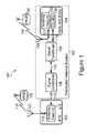
- FIG. 1depicts an exemplary system 100 for carrying out the invention.
- System 100includes a BTS 102 and a Distributed Antenna System (DAS) 103 .
- DAS 103includes a remote antenna entity (RAE) 104 , a signal conditioner 106 , a signal conditioner 108 , and a transport medium 110 .
- System 100also includes: (i) an antenna feed 112 providing a communication path between BTS 102 to signal conditioner 106 , and (ii) a communication connection 114 connecting RAE 104 to signal conditioner 108 .
- RAEremote antenna entity
- BTS 102may be part of a radio access network (RAN) for performing wireless communications.
- the RANmay include one or more other BTSs in addition to BTS 102 .
- BTS 102forms a corresponding cell and/or sector by radiating signals away from BTS 102 .
- the signals radiated away from BTS 102form an RF air interface 116 and may be arranged according to one of the CDMA, TDMA, or OFDMA air interface protocols or some other air interface protocol.
- the signals radiated away from BTS 102may be arranged as multiple forward-link communication channels.
- the forward-link communication channelsare for performing communications from BTS 102 to one or more wireless communication devices (including wireless communication device (WCD) 132 ).
- WCDwireless communication device
- the multiple forward-link communication channelsmay include a pilot channel, a medium access control channel, a control channel, a paging channel, a pilot channel, and/or a traffic channel.
- the traffic channelmay include a voice channel and/or a data channel.
- Other examples of forward-link communication channels and other examples of the quantity of forward-link communication channels that make up RF air interface 116are also possible.
- RF air interface 116also includes multiple reverse-link communication channels that radiate towards BTS 102 from one or more wireless communication devices (including WCD 132 ).
- the multiple reverse-link communication channelsare for performing communications from the one or more wireless communication devices (including WCD 132 ) to BTS 102 .
- the forward-link channels and the reverse-link channels of air interface 116are arranged according to the same air interface protocol.
- BTS 102may be connected to a variety of networks and/or network entities.
- BTS 102may be connected to a base station controller (BSC), which is then connected to a telecommunications switch or gateway, such as a mobile switching center (MSC) or packet data serving node (PDSN).
- MSCmobile switching center
- PDSNpacket data serving node
- the switch or gatewaymay then be connected with a transport network, such as the public switched telephone network (PSTN) or a packet-switched network (e.g., the Internet).
- PSTNpublic switched telephone network
- packet-switched networke.g., the Internet
- BTS 102includes an antenna feed interface 117 that connects to antenna feed 112 and an antenna feed 118 .
- Antenna feed 112connects BTS 102 to signal conditioner 106 (which connects to RAE 104 via the transport medium 110 and signal conditioner 108 ).
- Antenna feed 118connects BTS 102 to antenna 122 , and provides a communication path between BTS 102 and antenna 122 .
- BTS 102may include one or more other antenna feeds (not shown) and one or more other antennas (not shown). Each of the other antenna feeds may be connected to one or more of the other antennas.
- Antenna feed interface 117may be arranged for one or more sectors.
- antenna feed interface 117may be arranged to have (i) a first interface that connects to antenna feed 118 and is designated for a first sector, and (ii) a second interface that connects to antenna feed 112 and is designated for a second sector.
- Other exemplary arrangements of antenna feed interface 117are also possible.
- antenna feed 112may include one or more coaxial cables for carrying communications to BTS 102 from signal conditioner 106 , and one or more coaxial cables for carrying communications to signal conditioner 106 from BTS 102 .
- Other exemplary means of an antenna feed carrying communicationsare also possible.
- Antenna 122may receive signals from RF air interface 116 and provide the received signals to the BTS 102 via antenna feed 118 .
- BTS 102can receive other signals from other sources as well.
- BTS 102may be divided into multiple sectors and BTS 102 may receive signals sent from signal conditioner 106 via antenna feed 112 .
- BTS 102may provide signals for a certain sector to antenna 122 via antenna feed 118 .
- Another antenna feed 112connected to another sector of BTS 102 , can provide signals to RAE 104 via signal conditioner 106 , transport medium 110 , signal conditioner 108 , and communication connection 114 .
- Yet another sector of BTS 102may be connected via another antenna feed to another antenna or to another network entity connected to BTS 102 via the other antenna feed.
- Antenna 122radiates signals to form RF air interface 116 .
- BTS 102may include amplifier circuitry (not shown) for amplifying the signals provided to antenna feed 118 so that the signals propagated from antenna 122 are of sufficient power for a given sector or cell.
- DAS 103may be a part of the RAN that includes BTS 102 .
- DAS 103includes a RAE 104 and transport medium 110 .
- DAS 103may include one or more other remote antenna entities (not shown). Each of the other remote antenna entities of DAS 103 may perform communications using transport medium 110 and/or one or more other transport mediums (not shown).
- Each remote antenna entitymay include amplifier circuitry for amplifying an RF signal to be provided to an antenna feed and in turn, an antenna for radiating the amplified signal over an RF air interface.
- DAS 103extends the cell and/or sector(s) (corresponding to BTS 102 ) by radiating signals away from RAE 104 and the other remote antenna entities.
- the signals radiated away from RAE 104form an RF air interface 124 and are arranged according to the same air interface protocol as the air interface protocol for RF air interface 116 .
- signals radiated away from the other remote antenna entitiesform respective air interfaces arranged according to the same air interface protocol as the air interface protocol for RF air interface 116
- RAE 104may include (i) an antenna feed interface 125 , (ii) circuitry 126 for connecting to communication connection 114 and to antenna feed interface 125 , and (ii) an antenna feed 127 for connecting to an antenna 128 .
- Circuitry 126may include circuitry for providing signals between communication connection 114 and antenna feed 127 .
- RAE 104may include one or more other antenna feeds that connect to one or more other antennas.
- antenna feed interface 117may be arranged with (i) an interface that connects to antenna feed 127 and that is designated for a given sector, and (ii) one or more other interfaces that connect to the one or more other antenna feeds and that is designated for one or more other sectors.
- System 100provides means for performing wireless communications with multiple wireless communication devices.
- WCD 132may use RF air interface 116 to communicate wirelessly with BTS 102
- a WCD 134may use RF air interface 124 to communicate wirelessly with RAE 104 .
- BTS 102provides wireless service to both WCD 132 and WCD 134 , however, the wireless service provided by BTS 102 to WCD 134 is carried out, in part, by DAS 103 .
- One or more other wireless communication devicesmay also perform wireless communications with BTS 102 and/or the remote antenna entities of DAS 103 .
- WCD 132 and WCD 134may be arranged as any of a variety of wireless communication devices.
- WCD 132 and/or WCD 134may be arranged as a mobile WCD.
- a mobile WCDmay be arranged as a mobile phone, a wireless personal digital assistant (PDA), or a portable computer having a wireless network interface.
- PDAwireless personal digital assistant
- Other examples of a mobile WCDare also possible.
- WCD 132 and/or WCD 134may be arranged as a fixed WCD.
- a fixed WCDis a wireless device situated in a fixed location, such as an office or home.
- a fixed WCDtypically derives electrical power from a utility source provided to the fixed location, as opposed to a mobile WCD that normally derives electrical power from a battery.
- a fixed WCDmay be arranged as a wireless local loop hub that provides an interface between (i) conventional landline telephone equipment located at a fixed location, and (ii) the PSTN via the RAN that includes BTS 102 .
- Other examples of a fixed WCDare also possible.
- Signal conditioner 106includes an interface to antenna feed 112 and an interface to transport medium 110 .
- Signal conditioner 106includes means for receiving signals from antenna feed 112 and for conditioning these received signals for subsequent transmission over transport medium 110 .
- Signal conditioner 106also provides means for receiving signals from transport medium 110 and for conditioning these received signals for subsequent transmission to BTS 102 via antenna feed 112 . Additional details of signal conditioner 106 are described below with respect to FIG. 3 .
- Signal conditioner 108includes (i) an interface to communication connection 114 that connects to a RAE 104 , and (ii) an interface to transport medium 110 .
- Signal conditioner 108includes means for receiving signals from remote antenna entities (e.g., RAE 104 ) and for conditioning these received signals for subsequent transmission over transport medium 110 .
- Signal conditioner 108also provides means for receiving signals from transport medium 110 and for conditioning these received signals for subsequent transmission to remote antenna entities (e.g., RAE 104 ). Additional details of signal conditioner 108 are described below with respect to FIG. 4 .
- Transport medium 110provides means for transporting a combined digital signal between signal conditioner 106 and signal conditioner 108 . Transportation of the combined digital signal via transport medium 110 occurs by transporting the combined digital signal as information data over transport medium 110 .
- the combined digital signalcomprises the total information to be radiated from an antenna of BTS 102 (e.g., the total information to be radiated for one sector) or the total information to be transmitted from RAE 104 to BTS 102 .
- the total informationmay include (i) the information associated with multiple phone calls and/or data sessions being handled by BTS 102 , and (ii) control information.
- the combined digital signalmay be produced in BTS 102 by combining digital signals from multiple communication channels.
- BTS 102produces the combined digital signal by combining digital signals from multiple forward-link channels, such as any combination of the forward-link channels described above.
- RAE 104receives the RF signal over the air which contains signals for multiple reverse-link channels, such as any combination of the reverse-link channels described above.
- RAE 104sends the RF signal to signal conditioner 108 .
- Signal conditioner 108recovers the combined digital signal by demodulating the RF signal, which contains signals for multiple reverse-link channels.
- Transport medium 110may be arranged in various configurations.
- transport medium 110may be arranged as a broadband wireline transport medium.
- a broadband wireline transport mediummay be arranged as a coaxial cable transport medium, an optical fiber transport medium, a broadband over electrical power line transport medium, or a twisted pair of copper wires.
- a broadband wireline transport mediummay be arranged as a transport medium in compliance with International Telecommunication Union—Telecommunications (ITU-T) recommendation G.993.2 entitled Very - high - bit - rate Digital Subscriber Line 2.
- ITU-TInternational Telecommunication Union—Telecommunications
- G.993.2entitled Very - high - bit - rate Digital Subscriber Line 2.
- Other examples of a broadband wireline transport mediumare also possible.
- transport medium 110may be arranged as a broadband wireless transport medium.
- a broadband wireless transport mediummay be arranged as a transport medium using at least a portion (i.e., one or more frequencies) of a broadband radio spectrum (e.g., 2.495 GHz to 2.690 GHz), a free space optics transport medium, a millimeter wave transport medium, or a microwave radio transport medium.
- a broadband wireless transport mediummay also possible.
- transport medium 110may be arranged as a shared transport medium for transporting (i) a combined digital signal between signal conditioner 106 and signal conditioner 108 , and (ii) other data traffic to be transmitted to a destination without passing the data traffic through BTS 102 or RAE 104 .
- data traffic, transported over transport medium 100that includes a combined digital signal and other data traffic is referred to as combined data traffic.
- a variety of data trafficmay be transmitted as combined data traffic via transport medium 110 .
- data trafficmay include data being transmitted over Ethernet in accordance with the Institute of Electrical and Electronic Engineers (IEEE) 802.3 standards.
- IEEEInstitute of Electrical and Electronic Engineers
- data trafficmay include data being transmitted over a Synchronous Optical NETwork (SONET).
- SONETSynchronous Optical NETwork
- Other examples of data traffic that may be transmitted over transport medium 110are also possible.
- Antenna feed 112provides a communication path between BTS 102 and signal conditioner 106 .
- Multiple antenna feeds, each connected to a different sector of BTS 102may provide communication paths for transporting signals between BTS 102 and signal conditioner 106 .
- FIG. 2Adepicts transport medium 110 arranged as a shared transport medium carrying traffic from signal conditioner 106 towards signal conditioner 108 .
- signal conditioner 106receives an RF combined digital signal (CDS) 200 (from BTS 102 ) and outputs a conditioned CDS 202 .
- CDSRF combined digital signal
- the conditioned CDS 202 and other data traffic 204are carried over the shared transport medium 110 as combined data traffic 206 .
- the conditioned CDS 202 and the other data traffic 204may be combined to form combined data traffic 206 or they may be carried independently over independent carriers on transport medium 110 .
- the combined data traffic 206may be formed at signal conditioner 106 or by a means remote from signal conditioner 106 .
- the means remote from signal conditioner 106may include a network server operated by a service provider that operates transport medium 110 .
- the other data traffic 204may be provided directly to signal conditioner 106 .
- the combined data traffic 206may be formed by modulating the combined digital signal recovered from the RF CDS 200 onto a first set of sub-carriers or carriers and modulating the other data traffic 204 onto a second set of sub-carriers or carriers.
- the conditioned CDS 202 and the other data traffic 204may be combined onto a single carrier, such as a millimeter wave band carrier.
- the modulation of the combined digital signal recovered from the RF CDS 200 , the conditioned CDS 202 , and the other data traffic 204may be carried out using any of a variety of modulation techniques, such as BPSK (Binary Phase Shift Keying), QPSK (Quadrature Phase Shift Keying), or QAM (Quadrature Amplitude Modulation).
- modulation techniquessuch as BPSK (Binary Phase Shift Keying), QPSK (Quadrature Phase Shift Keying), or QAM (Quadrature Amplitude Modulation).
- Other examples of the various modulation techniques for modulating the combined digital signal recovered from the RF CDS 200 , the conditioned CDS 202 , and the other data traffic 204are also possible.
- the combined data traffic 206may be transported over the shared transport medium 110 as Ethernet packets.
- the conditioned CDS 202may comprise the CDS recovered from the RF CDS 200 , encapsulated as the payload of Ethernet packets, with a destination address of signal conditioner 108 , and a source address of the signal conditioner 106 that forms the Ethernet packets.
- the other data traffic 204is transported as the payload of other Ethernet packets, with other destination and source addresses.
- the conditioned CDS 202 and the other data traffic 204may be interleaved using any of a variety of interleaving techniques such as packet interleaving. Other examples of the various interleaving techniques for combining the conditioned CDS 202 and the other data traffic 204 are also possible.
- the conditioned CDS 202 and the other data traffic 204may be multiplexed using any variety of multiplexing techniques such as Frequency Division Duplexing (FDD), or Time Division Multiplexing (TDM). Other examples of multiplexing the conditioned CDS 202 and the other data traffic 204 are also possible.
- FDDFrequency Division Duplexing
- TDMTime Division Multiplexing
- Transmission of the combined data traffic 206 through transport medium 110allows for simultaneous transmission of the conditioned CDS 202 and the other data traffic 204 through the shared transport medium 110 .
- FIG. 2Aalso depicts the combined data traffic 206 being separated to recover the conditioned CDS 202 and the other data traffic 204 after the combined data traffic 206 has passed through transport medium 110 .
- the conditioned CDS 202is separated from the combined data traffic 206 and then provided to signal conditioner 108 .
- the other traffic data 204is separated from the combined data traffic 206 and may be provided to a network for delivery to an entity other than BTS 102 or DAS 103 .
- the separation of the combined data traffic 206 to obtain the conditioned CDS 202 and the other traffic data 204may be carried out in signal conditioner 108 .
- the separation of the combined data traffic 206 to obtain the conditioned CDS 202 and the other traffic data 204may be carried out at a means remote from signal conditioner 108 .
- FIG. 2Bdepicts transport medium 110 arranged as a shared transport medium carrying traffic from signal conditioner 108 towards signal conditioner 106 .
- signal conditioner 108receives an RF CDS 210 (from RAE 104 ) and outputs a conditioned CDS 212 .
- the conditioned CDS 212 and other data traffic 214are carried over the shared transport medium 110 as combined data traffic 216 .
- the conditioned CDS 212 and the other data traffic 214may be combined to form combined data traffic 216 or they may be carried independently over independent carriers on transport medium 110 .
- the combined data traffic 216may be formed at signal conditioner 108 or by a means remote from signal conditioner 108 .
- the means remote from signal conditioner 108may include a network server operated by a service provider that operates transport medium 110 .
- the other data traffic 214may be provided directly to signal conditioner 108 .
- the methods and means described herein for combining the conditioned CDS 202 and the other data traffic 204may also be used to combine the conditioned CDS 212 and the other data traffic 214 .
- the method and means described herein for transporting the combined data traffic 206 over transport medium 110may also be used for transporting the combined data traffic 216 over transport medium 110 .
- FIG. 2Balso depicts the combined data traffic 216 being separated to recover the conditioned CDS 212 and the other data traffic 214 after the combined data traffic 216 has passed through transport medium 110 .
- the conditioned CDS 212is separated from the combined data traffic 216 and is provided to signal conditioner 106 .
- the other traffic data 214is separated from the combined data traffic 216 may be provided to a network for delivery to an entity other than BTS 102 or DAS 103 .
- the separation of the combined data traffic 216 to obtain the conditioned CDS 212 and the other traffic data 214may be carried out in signal conditioner 106 .
- the separation of the combined data traffic 216 to obtain the conditioned CDS 212 and the other traffic data 214may be carried out at a means remote from signal conditioner 106 .
- FIG. 3depicts details of signal conditioner 106 which interfaces to BTS 102 .
- signal conditioner 106may include an antenna feed interface 302 that interfaces to BTS 102 via antenna feed 112 , a network interface 304 , a transport medium interface 306 , a demodulator 308 , a modulator 310 , a processor 312 , and data storage 314 , all linked together via a system bus, network, or other connection mechanism 316 .
- One or more of the components of signal conditioner 106may be combined.
- demodulator 308 and modulator 310may be combined as a single entity, i.e., a modem 318 .
- one or more of the components of signal conditioner 106may be omitted.
- Antenna feed interface 302may receive a signal representing a combined digital signal.
- antenna feed interface 302may receive the RF CDS 200 sent over antenna feed interface 112 from BTS 102 .
- BTS 102may include a modulator to produce the RF CDS 200 by modulating an RF carrier with a combined digital signal produced at BTS 102 .
- Network interface 304interfaces with one or more networks. These one or more networks may include one or more wireless networks and/or one or more wireline networks. Network interface 304 interfaces to the one or more networks by receiving data traffic (e.g., the other data traffic 204 ) from the one or more networks and/or by providing data traffic (e.g., the other data traffic 214 ) to the one or more networks. Signal conditioner 106 may not include network interface 304 if the conditioned CDS 202 and the other data traffic 204 are combined and separated at an entity remote from signal conditioner 106 .
- Network interface 304may interface with various types of wireless networks or wireline networks.
- network interface 304may interface with a wireline network including a twisted pair of cables configured for performing Ethernet communications.
- network interfacemay interface with an optical fiber network arranged as a SONET.
- network interface 304may interface with a wireline network including a Hybrid Fiber-Coax (HFC) for performing communications in accordance with the Data Over Cable Service Interface Specifications (DOCSIS), or in accordance with another specification or protocol.
- HFCHybrid Fiber-Coax
- DOCSISData Over Cable Service Interface Specifications
- Other examples of the various types of networks network interface 304 may interface withare also possible.
- Transport medium interface 306interfaces with transport medium 110 .
- Transport medium interface 306may interface with transport medium 110 by providing data to transport medium 110 .
- transport medium interface 306may provide the conditioned CDS 202 and the other data traffic 204 to transport medium 110 for transmission, in turn, to signal conditioner 108 .
- transport medium interface 306may provide the combined data traffic 206 to transport medium 110 for transmission, in turn, to signal conditioner 108 .
- Transport medium interface 306may also interface with transport medium 110 by receiving data from transport medium 110 .
- transport medium interface 306may receive the conditioned CDS 212 and the other data traffic 214 sent from signal conditioner 108 via transport medium 110 .
- transport medium interface 306may receive the combined data traffic 216 sent from signal conditioner 108 via transport medium 110 .
- Transport medium interface 306may include multiple transport medium interfaces for interfacing to multiple transport media.
- transport medium interface 306may include (i) one or more transport medium interfaces interfacing to a corresponding broadband wireline transport medium, and/or (ii) one or more transport medium interfaces interfacing to a corresponding broadband wireless transport medium.
- each of the multiple transport medium interfacesmay be arranged as an interface card pluggable into and removable from a backplane.
- the backplanemay be arranged for holding the transport media interfaces while the interfaces are operational.
- the arrangement of using pluggable and removable interface cardsis advantageous for at least the reason that an entity operating the pluggable and removable interface cards may switch transport media interfaces at a preferred time.
- the preferred time to switch transport media interfacesmay be when a particular transport medium interface stops functioning.
- the preferred time to switch transport medium interfacesmay be after the entity enters into an agreement with another entity operating a new transport medium.
- Demodulator 308may comprise one or more demodulators for conditioning signals by demodulating the signals.
- demodulator 308may include a first demodulator for demodulating signals received at antenna feed interface 302 , a second demodulator for demodulating signals received at network interface 304 , and a third demodulator for demodulating signals received from transport medium interface 306 .
- demodulation of signals or data streams received at network interface 304 or transport medium interface 306may not be necessary. Instead, those signals or data streams may receive a different treatment (e.g., conditioning) as appropriate.
- Demodulator 308may receive the RF CDS 200 from antenna feed interface 302 .
- Demodulator 308may demodulate the RF CDS 200 so as to recover the combined digital signal and then provide the recovered combined digital signal to another conditioning device of signal conditioner 106 .
- demodulator 308may provide the recovered combined digital signal to modulator 310 or to processor 312 .
- Demodulator 308may demodulate other signals as well, such as a signal received at network interface 304 or transport medium interface 306 . Demodulator 308 may demodulate each signal received at demodulator 308 so as to recover (e.g., extract) a combined digital signal or the other data traffic 204 represented by the received signal. After recovering the combined digital signal, demodulator 308 may provide the recovered combined digital signal or the other data traffic 204 to another portion of signal conditioner 106 .
- Modulator 310may comprise one or more modulators that each modulate a given carrier with a respective signal. Modulator 310 may receive the signals to modulate the given carriers from other portions of signal conditioner 106 (e.g., demodulator 308 or processor 312 ). As an example, modulator 310 may (i) receive a combined digital signal recovered from RF CDS 200 by demodulator 308 , and (ii) modulate a carrier with the combined digital signal so as to produce a signal representing the combined digital signal. This signal may comprise conditioned CDS 202 .
- modulator 310may include a modulator for modulating signals to be transmitted to network interface 304 or to transport medium interface 306 .
- modulator 310may modulate a carrier in accordance with any of a variety of modulation schemes.
- modulator 310may modulate the carrier in accordance with the Binary Phase Shift Keying (BPSK), the Quadrature Phase Shift Keying (QPSK), the 16-state Quadrature Amplitude Modulation (16QAM), or the 256-state Quadrature Amplitude Modulation (256QAM), or any other modulation scheme now known or later developed.
- BPSKBinary Phase Shift Keying
- QPSKQuadrature Phase Shift Keying
- 16QAM16-state Quadrature Amplitude Modulation
- 256QAM256-state Quadrature Amplitude Modulation
- modulator 310may include a modulator for modulating signals to be sent to antenna feed interface 302 and, in turn, antenna feed 112 .
- this modulatormay modulate signals in accordance with the CDMA, TDMA, OFDMA, or some other air interface protocol used by BTS 102 .
- modem 318may comprise a modem within a chipset identified as Mobile Station ModemTM (MSMTM) and manufactured by Qualcomm, Inc. of San Diego, Calif. Qualcomm, Inc. manufactures a variety of MSMTM chipsets such as the MSM6800 chipset that supports CDMA2000 1X, CDMA2000 1XEV-DO, and GSM/GPRS networks.
- MSMTMMobile Station Modem
- An advantage of using an MSMTM chipset as modem 318is that the MSMTM chipset is already available for use to perform at least a portion of the demodulation and modulation performed by signal conditioner 300 .
- Other examples of modem 318are also possible.
- Processor 312may comprise one or more processors (e.g., one or more general purpose processors and/or one or more digital signal processors). Processor 312 may execute program instructions stored in data storage 314 and/or in firmware. In response to executing the program instructions, processor 312 may interact with antenna feed interface 302 , network interface 304 , transport medium interface 306 , demodulator 308 , and/or modulator 310 so as to carry out conditioning of signals and other functions described herein. As an example, processor 312 may (i) receive a combined digital signal recovered from RF CDS 200 by demodulator 308 , and (ii) condition the combined digital signal by encapsulating it as the payload in Ethernet packets. These packets may comprise conditioned CDS 202 .
- processorse.g., one or more general purpose processors and/or one or more digital signal processors.
- Processor 312may execute program instructions stored in data storage 314 and/or in firmware. In response to executing the program instructions, processor 312 may interact with
- Data storage 314comprises a computer readable medium.
- a computer readable mediummay comprise volatile and/or non-volatile storage components, such as optical, magnetic, organic or other memory or disc storage, which can be integrated in whole or in part with processor 312 .
- program instructionsmay be stored in data storage 314 and/or in firmware.
- the program instructionsmay include instructions executable by processor 312 to cause transport medium interface 306 to provide the conditioned CDS 202 and/or the other data traffic 204 to transport medium 110 .
- the program instructionsmay include instructions for communicating to RAE 104 data that indicates (i) a first frequency for transmitting an RF combined digital signal over the air from an antenna, and (ii) a second frequency for the antenna to receive RF signals transmitted over the air.
- the program instructionsmay include instructions that cause processor 312 to select (for use) a particular transport medium interface, from among multiple transport medium interfaces of transport medium interface 306 that interface with transport medium 110 .
- these program instructionsmay include instructions for responding to a message, received from a remote device (e.g., a remote signal conditioner or another network entity), that indicates the particular transport medium interface should be selected.
- the remote devicemay send the message in response to detecting that a previously selected transport medium has failed (e.g., not performing communications).
- Other examples of program instructions storable in data storage 314 or in firmwareare also possible.
- FIG. 4depicts details of signal conditioner 108 which interfaces to RAE 104 .
- signal conditioner 108includes a communication connection interface 402 that interfaces to communication connection 114 (and, in turn, to RAE 104 via communication connection 114 ), a network interface 404 , a transport medium interface 406 , a demodulator 408 , a modulator 410 , a processor 412 , and data storage 414 , all linked together via a system bus, network, or other connection mechanism 416 .
- One or more of the components of signal conditioner 108may be combined.
- demodulator 408 and modulator 410may be combined as a single entity, i.e., a modem 418 .
- one or more of the components of signal conditioner 108may be omitted.
- One or more of the components of signal conditioner 108may be identical to components in signal conditioner 106 . However the interface components of signal conditioner 106 and the interface components of signal conditioner 108 may interface to different entities or at different locations of a common entity.
- communication connection interface 402connects to RAE 104 via communication connection 114
- antenna feed interface 302connects to BTS 102 via antenna feed 112 .
- network interface 304may interface to a first data transport network and network interface 404 may interface to a second data transport network.
- transport medium interface 306interfaces to transport medium 110 at a first location and transport medium interface 406 interfaces to transport medium interface 110 as a second location.
- Demodulator 408may comprise one or more demodulators for conditioning signals by demodulating the signals.
- demodulator 408may include a first demodulator for demodulating signals received at communication connection interface 402 , a second demodulator for demodulating signals received at network interface 404 , and a third demodulator for demodulating signals received from transport medium interface 406 .
- Demodulator 408may receive the RF CDS 210 from communication connection interface 402 . Demodulator 408 may demodulate the RF CDS 210 so as to recover the combined digital signal and then provide the recovered combined digital signal to another conditioning device of signal conditioner 108 . For example, demodulator 408 may provide the recovered combined digital signal to modulator 410 or to processor 412 .
- Demodulator 408may demodulate other signals as well, such as a signal received at network interface 404 or transport medium interface 406 . Demodulator 408 may demodulate each signal received at demodulator 408 so as to recover (e.g., extract) a combined digital signal or the other data traffic 214 represented by the received signal. After recovering the combined digital signal, demodulator 408 may provide the recovered combined digital signal or the other data traffic 214 to another portion of signal conditioner 108 .
- Modulator 410may include one or more modulators for modulating carrier signals.
- modulator 410may include a first modulator for modulating a first carrier to be sent via communication connection interface 402 , a second modulator for modulating a second carrier to be sent via network interface 404 , and a third modulator for modulating a third carrier to be sent via transport medium interface 406 .
- modulator 410may modulate an RF carrier with a combined digital signal so as to produce an RF signal representing the combined digital signal.
- This RF carrier modulated by modulator 410is typically a carrier having a frequency substantially identical to the frequency of an RF carrier modulated at BTS 102 to produce the RF signal provided to signal conditioner 106 via antenna feed 112 .
- Processor 412may execute program instructions stored in firmware or in data storage 414 .
- the program instructions executed by processor 412are similar to the instructions executed by processor 312 except that the instructions executed by processor 412 are for communicating data from signal conditioner 108 to RAE 104 or from signal conditioner 108 towards BTS 102 via transport medium 110 .
- signal conditioner 108may be physically separate from RAE 104 .
- signal conditioner 108 , communication connection 114 , and RAE 104may be integrated (e.g., combined) into a signal conditioning remote antenna entity that connects directly to transport medium 110 .
- the signal conditioning remote antenna entitymay include one or more antenna feeds for connecting to one or more antennas.
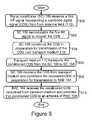
- FIG. 5is a flow chart provided to illustrate some of the functions that may be carried out in accordance with exemplary embodiments of the present invention. The functions shown in FIG. 5 are for use in performing communications from BTS 102 to RAE 104 of DAS 103 , as well as other remote antenna entities of DAS 103 .
- signal conditioner 106receives a first RF signal representing a combined digital signal (e.g., RF CDS 200 ).
- Signal conditioner 106receives the RF CDS 200 via antenna feed 112 .
- BTS 102produces the first combined digital signal and the RF CDS 200 .
- the BTS 102produces the combined digital signal by combining digital signals from multiple communication channels and control channels.
- the multiple communication channels and control channelsmay be forward-link channels in accordance with any air interface protocol.
- the multiple communication channels and control channelsmay include forward-link channels in accordance with the CDMA air interface protocol, the TDMA air interface protocol, or the OFDMA air interface protocol.
- Other examples of the multiple communication channels and control channelsare also possible.
- the BTS 102may produce the RF CDS 200 by modulating a first carrier with the combined digital signal.
- the first carriermay comprise an RF carrier such that the RF CDS 200 is an RF signal suitable for transmission to antenna feed 118 for subsequent transmission from antenna 122 .
- the RF CDS 200may include an RF signal representing a combined digital signal in accordance with the CDMA air interface protocol, the TDMA air interface protocol, the OFDMA air interface protocol, or some other air interface protocol.
- Signal conditioner 106receives the RF CDS 200 at antenna feed interface 302 .
- antenna feed interface 302provides the RF CDS 200 to demodulator 308 via connection mechanism 316 .
- signal conditioner 106demodulates the RF CDS 200 so as to recover the combined digital signal.
- Demodulation of the RF CDS 200may be carried out by demodulator 308 (e.g., a first demodulator that connects to antenna feed interface 302 ).
- demodulator 308may provide the recovered combined digital signal to another conditioning device of signal conditioner 106 , such as the modulator 310 or the processor 312 .
- signal conditioner 106conditions the combined digital signal in preparation for transmission of the combined digital signal over transport medium 110 .
- Conditioning the combined digital signalmay include conditioning the signal for transmission over various types of transport media (e.g., a wireless transport medium or a wireline transport medium).
- Conditioning the combined digital signalresults in production of a conditioned combined digital signal (e.g., conditioned CDS 202 ).
- modulator 310may carry out at least a portion of the conditioning of the combined digital signal.
- modulator 310may modulate a second carrier with the recovered combined digital signal so as to produce the conditioned CDS 202 .
- the second carriermay include an RF carrier such that the conditioned CDS 202 is an RF modulated signal.
- modulator 310may provide the conditioned CDS 202 to transport medium interface 306 or to processor 312 , via connection mechanism 316 .
- processor 312may execute program instructions to carry out at least a portion of the conditioning of the combined digital signal.
- Processor 312may (i) receive the conditioned CDS 202 from modulator 310 and perform additional conditioning to the conditioned CDS 202 , or (ii) receive the combined digital signal directly from demodulator 308 and perform conditioning to the combined digital signal.
- Processor 312may carry out conditioning of the combined CDS 202 or the combined digital signal in various ways.
- processor 312may execute program instructions to carry out combining the conditioned CDS 202 with the other data traffic 204 received at network interface 304 so as to produce the combined data traffic 206 .
- processor 312may execute program instructions to condition the combined digital signal by interleaving or multiplexing the combined digital signal with the other data traffic 204 .
- processor 312may execute program instructions to condition the combined digital signal by placing the combined digital signal, alone or in combination with the other data traffic 204 , into packets such as Ethernet packets as specified by IEEE 802.3 standards.
- Other examples of processor 312 executing program instructions to carry out conditioning of the conditioned CDS 202 or the combined digital signalare also possible.
- transport medium 110transports the conditioned CDS 202 from signal conditioner 106 to signal conditioner 108 or to multiple signal conditioners which interface to remote antenna entities of DAS 103 .
- transmission of the conditioned CDS 202 over transport medium 110may be carried out via a single transport medium capable of transporting the conditioned CDS 202 .
- the conditioned CDS 202may be transmitted over a broadband wireline transport medium or a broadband wireless transport medium.
- Signal conditioner 106 or another entitymay combine the conditioned CDS 202 and the other data traffic 204 to form the combined data traffic 206 .
- processor 312may execute program instructions to carry out forming the combined data traffic 206 from the conditioned CDS 202 and the other data traffic 204 .
- a network server remote from signal conditioner 106may combine the conditioned CDS 202 and the other data traffic 204 to provide the combined data traffic 206 .
- processor 312(or the network server) may provide the combined data traffic 206 to transport medium interface 306 for subsequent transmission over transport medium 110 .
- signal conditioner 108recovers the conditioned CDS 202 transported over transport medium 110 and subsequently conditions the recovered CDS in preparation for transmission of the recovered CDS to the RAE 104 .
- signal conditioner 108may receive the combined data traffic 206 at transport medium interface 406 and responsively provide the combined data traffic 206 to processor 412 .
- processor 412may execute program instructions to (i) separate the combined data traffic 206 to recover the conditioned CDS 202 and the other data traffic 204 , (ii) condition the recovered conditioned CDS 202 , (e.g., by providing the conditioned CDS 202 to demodulator 408 if the conditioned CDS 202 is modulated), or perform other conditioning methods if the conditioned CDS 202 is packetized, and (iii) provide the other data traffic 204 to network interface 404 .
- network interface 404may transmit the other data traffic 204 to its destination via a network interfacing to network interface 404 .
- Signal conditioner 108may not include network interface 404 if the conditioned CDS 212 and the other data traffic 214 are combined and separated at an entity remote from signal conditioner 108 .
- Signal conditioner 108may provide the conditioned CDS 202 to modulator 410 .
- Modulator 410modulates an RF carrier with the conditioned CDS 202 , recovered at signal conditioner 108 , so as to produce an RF signal representing the combined digital signal (e.g., RF CDS 208 ).
- modulator 410may perform modulation in accordance with the CDMA protocol.
- the RF CDS 208may be arranged as a CDMA RF signal.
- Other examples of the modulation performed to produce the RF CDS 208such as TDMA modulation or OFDMA modulation are also possible.
- An output of modulator 410transmits the RF CDS 208 to communication connection interface 402 .
- Communication connection interface 402transmits the RF CDS 208 to RAE 104 via communication connection 114 .
- RAE 104receives the combined digital signal as conditioned at signal conditioner 108 (i.e., RAE 104 may receive the RF CDS 208 ).
- RAE 104receives the RF CDS 208 from signal conditioner 108 via communication connection 114 .
- RAE 104may provide the RF CDS 208 directly to antenna feed 127 for propagating the RF CDS 208 away from antenna 128 .
- RAE 104may receive the combined digital signal arranged as the conditioned CDS 202 and perform additional conditioning to the conditioned CDS 202 so as to produce the RF CDS 208 .
- RAE 104may then provide the RF CDS 208 to antenna feed 127 for transmitting of the RF CDS 208 from antenna 128 .
- RAE 104may perform additional conditioning of the conditioned CDS 202 to produce the RF CDS 208 .
- RAE 104may condition the conditioned CDS 202 by modulating an RF carrier with the conditioned CDS 202 so as to form the RF CDS 208 .
- the RF carrier modulated at the RAE 104may be substantially identical to the RF carrier modulated at BTS 102 to form RF CDS 200 .
- RAE 104may amplify the RF CDS 208 to produce an RF signal suitable for transmitting via antenna 128 .
- RAE 104may provide the RF CDS 208 to antenna feed 127 .
- Antenna feed 127provides means for transporting the RF CDS 208 to antenna 128 .
- Antenna 128provides means for propagating the RF CDS 208 away from RAE 104 . Since RF CDS 208 represents the combined digital signal produced at BTS 102 , propagating the RF CDS 208 away from RAE 104 extends the range of BTS 102 . Propagating the RF CDS 208 away from RAE 104 extends the range of BTS 102 because the combined digital signal is propagated over air interface 124 which provides wireless service in an area different than air interface 116 .
- blocks 508 and 510may be combined such that the signal conditioning remote antenna entity (i) receives the combined digital signal (e.g., in the form of the conditioned CDS 202 or the combined data traffic 206 ) from transport medium 110 , and (ii) conditions the combined digital signal to form RF CDS 208 to be propagated from an antenna connected to the signal conditioning remote antenna entity.
- the signal conditioning remote antenna entitymay then propagate the RF CDS 208 from antenna 128 or from antenna 128 and one or more other antennas.
- FIG. 6is a flow chart provided to illustrate some of the functions that may be carried out in accordance with exemplary embodiments of the present invention. The functions shown in FIG. 6 are described below as functions for performing communications in a direction from RAE 104 to BTS 102 .
- signal conditioner 108receives an RF signal representing a combined digital signal (e.g., RF CDS 210 ).
- Signal conditioner 108receives the RF CDS 210 from RAE 104 via communication connection 114 .
- RAE 104receives RF CDS 210 from antenna 128 , which receives the signal over RF air interface 124 .
- the RF CDS 210includes multiple communication channels and control channels.
- the multiple communication channels and control channelsmay be reverse-link channels in accordance with any air interface protocol.
- the multiple communication channels and control channelsmay include reverse-link channels in accordance with the CDMA air interface protocol, the TDMA air interface protocol, or the OFDMA air interface protocol.
- Other examples of the multiple communication channels and control channelsare also possible.
- Signal conditioner 108receives the RF CDS 210 at communication connection interface 402 .
- communication connection interface 402provides the RF CDS 210 to demodulator 408 via connection mechanism 416 .
- signal conditioner 108demodulates the RF CDS 210 so as to recover the combined digital signal from the RF CDS 210 provided by RAE 104 .
- Demodulation of the RF CDS 210may be carried out by demodulator 408 (e.g., a first demodulator that connects to communication connection interface 402 ).
- demodulator 408may provide the recovered combined digital signal to a conditioning device of signal conditioner 108 , such as the modulator 410 or the processor 412 .
- signal conditioner 108conditions the combined digital signal in preparation for transmission of the combined digital signal over transport medium 110 .
- Conditioning the combined digital signalmay include conditioning the signal for transmission over various types of transport media (e.g., a wireless transport medium and a wireline transport medium).
- transport mediae.g., a wireless transport medium and a wireline transport medium.
- a conditioned combined digital signale.g., conditioned CDS 212 ) is produced.
- modulator 410may carry out at least a portion of the conditioning of the combined digital signal.
- modulator 410may modulate a carrier with the recovered combined digital signal so as to produce the conditioned CDS 212 .
- This carriermay include an RF carrier such that the conditioned CDS 212 is an RF modulated signal.
- modulator 410may provide the conditioned CDS 212 to transport medium interface 406 or to processor 412 , via connection mechanism 416 .
- processor 412may execute program instructions to carry out at least a portion of the conditioning of the combined digital signal.
- Processor 412may receive the conditioned CDS 212 from modulator 410 and perform additional conditioning to the conditioned CDS 212 or receive the combined digital signal directly from demodulator 408 .
- Processor 412may carry out conditioning of the combined CDS 212 or the combined digital signal in various ways.
- processor 412may execute program instructions to carry out combining the conditioned CDS 212 with the other data traffic 214 received at network interface 404 so as to produce the combined data traffic 216 .
- processor 412may execute program instructions to condition the combined digital signal by interleaving or multiplexing the combined digital signal with the other data traffic 214 .
- processor 412may execute program instructions to condition the combined digital signal by placing the combined digital signal, alone or in combination with the other data traffic 214 , into packets such as Ethernet packets as specified by IEEE 802.3 standards.
- Other examples of processor 412 executing program instructions to carry out conditioning of the conditioned CDS 212 or the combined digital signalare also possible.
- signal conditioner 108After conditioning the RF CDS 210 to produce the conditioned CDS 212 , signal conditioner 108 provides the conditioned CDS 212 to transport medium interface 406 for subsequent transmission of the conditioned CDS 212 over transport medium 110 . Alternatively, if signal conditioner 108 combines the combined digital signal recovered from the RF CDS 210 or the conditioned CDS 212 , with other data traffic 214 to form combined data traffic 216 , then signal conditioner 108 may provide the combined digital signal to transport medium 110 by providing the combined data traffic 216 to transport medium 110 .
- transport medium 110transports the conditioned CDS 212 from signal conditioner 108 to signal conditioner 106 .
- transmission of the conditioned CDS 212 over transport medium 110may be carried out via a single transport medium capable of transporting the conditioned CDS 212 .
- the conditioned CDS 212may be transmitted over a broadband wireline transport medium or a broadband wireless transport medium.
- transmission of the conditioned CDS 212 over transport medium 110may be carried out via transport media capable of transporting the conditioned CDS 212 .
- the conditioned CDS 212may be transmitted over transport media comprising a broadband wireline transport medium and a broadband wireless transport medium.
- the entire conditioned CDS 212may be transmitted over both the broadband wireline transport medium and the broadband wireless transport medium substantially simultaneously.
- a first portion of the conditioned CDS 212may be transmitted over the broadband wireline transport medium and a second portion of the conditioned CDS 212 may be transmitted over the broadband wireless transport medium.
- transport medium 110may function as a shared transport medium so as to transport the conditioned CDS 212 and the other data traffic 214 over transport medium 110 .
- transport medium 110may transport the conditioned CDS 212 and the other data traffic 214 individually or as combined data traffic 216 .
- Signal conditioner 108 or another entitymay combine the conditioned CDS 212 and the other data traffic 214 to form the combined data traffic 216 .
- processor 412may execute program instructions to carry out forming the combined data traffic 216 from the conditioned CDS 212 and the other data traffic 214 . After formation of the combined data traffic 216 , processor 412 may provide the combined data traffic 216 to transport medium interface 406 for subsequent transmission over transport medium 110 .
- a network server remote from signal conditioner 108may combine the conditioned CDS 212 and the other data 214 to provide the combined data traffic 216 .
- Signal conditioner 106may receive the conditioned CDS 212 separately or within the combined data traffic 216 that includes the conditioned CDS 212 and the other data traffic 214 . Signal conditioner 106 receives the conditioned CDS 212 at transport medium interface 306 .
- signal conditioner 106recovers the conditioned CDS 212 transported over transport medium 110 and subsequently conditions the recovered CDS in preparation for transmission of the recovered CDS to the BTS 102 .
- Signal conditioner 106recovers the CDS from the conditioned CDS 212 using a method appropriate for how the conditioned CDS 212 is transported across transport medium 110 . For example, if conditioned CDS 212 is transported across transport medium 110 as a modulated signal, the conditioned CDS 212 may be sent to demodulator 308 . In this way, demodulator 308 can demodulate the conditioned signal 212 so as to recover the conditioned digital signal.
- signal conditioner 106may receive the combined data traffic 216 at transport medium interface 306 and responsively provide the combined data traffic to processor 312 .
- processor 312may execute program instructions to (i) separate the combined data traffic 216 to recover the conditioned CDS 212 and the other data traffic 214 , (ii) condition the recovered conditioned CDS 212 , (e.g., by providing the conditioned CDS 212 to demodulator 308 if the conditioned CDS 212 is modulated), or perform other conditioning methods if the conditioned CDS 212 is packetized, and (iii) provide the other data traffic 214 to network interface 304 .
- network interface 304may transmit the other data traffic 214 to its destination via a network interfacing to network interface 304 .
- a network entity located between transport medium 110 and signal conditioner 106may (i) receive the combined data traffic 216 , (ii) separate the combined data traffic 216 to recover the conditioned CDS 212 and the other data traffic 214 , (iii) provide the conditioned CDS 212 to signal conditioner 106 , and (iv) provide the other data traffic 214 to a network that interfaces to this network entity.
- signal conditioner 106may receive the conditioned CDS 212 and use demodulator 308 and/or processor 312 to condition the conditioned CDS 212 as described above.
- Signal conditioner 106may provide the conditioned CDS 212 to modulator 310 .
- Modulator 310modulates an RF carrier with the conditioned CDS 212 , recovered at signal conditioner 106 , so as to produce an RF signal representing the combined digital signal (e.g., RF CDS 218 ).
- modulator 310may perform modulation in accordance with the CDMA protocol.
- the RF CDS 218may be arranged as a CDMA RF signal.
- Other examples of the modulation performed to produce the RF CDS 218such as TDMA modulation or OFDMA modulation are also possible.
- An output of modulator 310transmits the RF CDS 218 to antenna feed interface 302 .
- Antenna feed interface 302transmits the RF CDS 218 to BTS 102 via antenna feed 112 .
- BTS 102receives the combined digital signal as conditioned at signal conditioner 106 .
- BTS 102may receive the combined digital signal by receiving the RF CDS 218 that represents the combined digital signal.
- BTS 102receives the RF CDS 218 from signal conditioner 106 via antenna feed 112 .
- the BTS 102may recover the combined digital signal from the RF CDS 218 and then separate the combined digital signal to obtain data from the communication and control channels used to form the combined digital signal, process this data, and then transmit this processed data to its destination as appropriate to an entity of a transport network (e.g., a gateway of a packet switched network or a switch in a circuit-switched network).
- a transport networke.g., a gateway of a packet switched network or a switch in a circuit-switched network.
- Other examples of BTS 102 communicating the RF CDS 218 or the combined digital signalare also possible.
Landscapes
- Engineering & Computer Science (AREA)
- Computer Networks & Wireless Communication (AREA)
- Signal Processing (AREA)
- Mobile Radio Communication Systems (AREA)
Abstract
Description
Claims (36)
Priority Applications (1)
| Application Number | Priority Date | Filing Date | Title |
|---|---|---|---|
| US11/378,998US7634250B1 (en) | 2006-03-17 | 2006-03-17 | Signal conditioner and method for communicating over a shared transport medium a combined digital signal for wireless service |
Applications Claiming Priority (1)
| Application Number | Priority Date | Filing Date | Title |
|---|---|---|---|
| US11/378,998US7634250B1 (en) | 2006-03-17 | 2006-03-17 | Signal conditioner and method for communicating over a shared transport medium a combined digital signal for wireless service |
Publications (1)
| Publication Number | Publication Date |
|---|---|
| US7634250B1true US7634250B1 (en) | 2009-12-15 |
Family
ID=41403333
Family Applications (1)
| Application Number | Title | Priority Date | Filing Date |
|---|---|---|---|
| US11/378,998Active2028-04-09US7634250B1 (en) | 2006-03-17 | 2006-03-17 | Signal conditioner and method for communicating over a shared transport medium a combined digital signal for wireless service |
Country Status (1)
| Country | Link |
|---|---|
| US (1) | US7634250B1 (en) |
Cited By (174)
| Publication number | Priority date | Publication date | Assignee | Title |
|---|---|---|---|---|
| US20080109854A1 (en)* | 2006-11-06 | 2008-05-08 | Casavant Scott D | Satellite television ip bitstream generator receiving unit |
| US20080120655A1 (en)* | 2006-11-22 | 2008-05-22 | The Directv Group, Inc. | Integrated satellite master antenna television unit |
| US7848731B1 (en)* | 2007-08-14 | 2010-12-07 | Sprint Spectrum L.P. | System and method for communicating a combined digital signal for wireless service via integrated hybrid fiber coax and power line communication devices for a distributed antenna system over shared broadband media |
| US20110202952A1 (en)* | 2005-09-02 | 2011-08-18 | The Directv Group, Inc. | Network fraud prevention via registration and verification |
| US8024759B2 (en) | 2005-04-01 | 2011-09-20 | The Directv Group, Inc. | Backwards-compatible frequency translation module for satellite video delivery |
| US20110231881A1 (en)* | 2002-09-25 | 2011-09-22 | The Directv Group, Inc. | Direct broadcast signal distribution methods |
| US8050291B1 (en) | 2007-08-14 | 2011-11-01 | Sprint Spectrum L.P. | System and method for indoor wireless service distribution via ultra-wideband signals, and aggregation of combined digital signals for wireless service |
| US8238813B1 (en)* | 2007-08-20 | 2012-08-07 | The Directv Group, Inc. | Computationally efficient design for broadcast satellite single wire and/or direct demod interface |
| US8509722B2 (en) | 2009-01-06 | 2013-08-13 | The Directv Group, Inc. | Frequency drift estimation for low cost outdoor unit frequency conversions and system diagnostics |
| US8549565B2 (en) | 2005-04-01 | 2013-10-01 | The Directv Group, Inc. | Power balancing signal combiner |
| US8621525B2 (en) | 2005-04-01 | 2013-12-31 | The Directv Group, Inc. | Signal injection via power supply |
| US20140155054A1 (en)* | 2012-12-05 | 2014-06-05 | At&T Intellectual Property I, L.P. | Backhaul link for distributed antenna system |
| US8789115B2 (en) | 2005-09-02 | 2014-07-22 | The Directv Group, Inc. | Frequency translation module discovery and configuration |
| US9042812B1 (en) | 2013-11-06 | 2015-05-26 | At&T Intellectual Property I, Lp | Surface-wave communications and methods thereof |
| US9209902B2 (en) | 2013-12-10 | 2015-12-08 | At&T Intellectual Property I, L.P. | Quasi-optical coupler |
| US9312919B1 (en) | 2014-10-21 | 2016-04-12 | At&T Intellectual Property I, Lp | Transmission device with impairment compensation and methods for use therewith |
| US9461706B1 (en) | 2015-07-31 | 2016-10-04 | At&T Intellectual Property I, Lp | Method and apparatus for exchanging communication signals |
| US9490869B1 (en) | 2015-05-14 | 2016-11-08 | At&T Intellectual Property I, L.P. | Transmission medium having multiple cores and methods for use therewith |
| US9503189B2 (en) | 2014-10-10 | 2016-11-22 | At&T Intellectual Property I, L.P. | Method and apparatus for arranging communication sessions in a communication system |
| US9509415B1 (en) | 2015-06-25 | 2016-11-29 | At&T Intellectual Property I, L.P. | Methods and apparatus for inducing a fundamental wave mode on a transmission medium |
| US20160360533A1 (en)* | 2015-06-03 | 2016-12-08 | At&T Intellectual Property I, Lp | Network termination and methods for use therewith |
| US9520945B2 (en) | 2014-10-21 | 2016-12-13 | At&T Intellectual Property I, L.P. | Apparatus for providing communication services and methods thereof |
| US9525524B2 (en) | 2013-05-31 | 2016-12-20 | At&T Intellectual Property I, L.P. | Remote distributed antenna system |
| US9525210B2 (en) | 2014-10-21 | 2016-12-20 | At&T Intellectual Property I, L.P. | Guided-wave transmission device with non-fundamental mode propagation and methods for use therewith |
| US9531427B2 (en) | 2014-11-20 | 2016-12-27 | At&T Intellectual Property I, L.P. | Transmission device with mode division multiplexing and methods for use therewith |
| US9564947B2 (en) | 2014-10-21 | 2017-02-07 | At&T Intellectual Property I, L.P. | Guided-wave transmission device with diversity and methods for use therewith |
| US9577307B2 (en) | 2014-10-21 | 2017-02-21 | At&T Intellectual Property I, L.P. | Guided-wave transmission device and methods for use therewith |
| US9608692B2 (en) | 2015-06-11 | 2017-03-28 | At&T Intellectual Property I, L.P. | Repeater and methods for use therewith |
| US9608740B2 (en) | 2015-07-15 | 2017-03-28 | At&T Intellectual Property I, L.P. | Method and apparatus for launching a wave mode that mitigates interference |
| US9615269B2 (en) | 2014-10-02 | 2017-04-04 | At&T Intellectual Property I, L.P. | Method and apparatus that provides fault tolerance in a communication network |
| US9628854B2 (en) | 2014-09-29 | 2017-04-18 | At&T Intellectual Property I, L.P. | Method and apparatus for distributing content in a communication network |
| US9628116B2 (en) | 2015-07-14 | 2017-04-18 | At&T Intellectual Property I, L.P. | Apparatus and methods for transmitting wireless signals |
| US9640850B2 (en) | 2015-06-25 | 2017-05-02 | At&T Intellectual Property I, L.P. | Methods and apparatus for inducing a non-fundamental wave mode on a transmission medium |
| US9654173B2 (en) | 2014-11-20 | 2017-05-16 | At&T Intellectual Property I, L.P. | Apparatus for powering a communication device and methods thereof |
| US9653770B2 (en) | 2014-10-21 | 2017-05-16 | At&T Intellectual Property I, L.P. | Guided wave coupler, coupling module and methods for use therewith |
| US9667317B2 (en) | 2015-06-15 | 2017-05-30 | At&T Intellectual Property I, L.P. | Method and apparatus for providing security using network traffic adjustments |
| US9680670B2 (en) | 2014-11-20 | 2017-06-13 | At&T Intellectual Property I, L.P. | Transmission device with channel equalization and control and methods for use therewith |
| US9685992B2 (en) | 2014-10-03 | 2017-06-20 | At&T Intellectual Property I, L.P. | Circuit panel network and methods thereof |
| US9692101B2 (en) | 2014-08-26 | 2017-06-27 | At&T Intellectual Property I, L.P. | Guided wave couplers for coupling electromagnetic waves between a waveguide surface and a surface of a wire |
| US9705561B2 (en) | 2015-04-24 | 2017-07-11 | At&T Intellectual Property I, L.P. | Directional coupling device and methods for use therewith |
| US9705571B2 (en) | 2015-09-16 | 2017-07-11 | At&T Intellectual Property I, L.P. | Method and apparatus for use with a radio distributed antenna system |
| US9722318B2 (en) | 2015-07-14 | 2017-08-01 | At&T Intellectual Property I, L.P. | Method and apparatus for coupling an antenna to a device |
| US9729197B2 (en) | 2015-10-01 | 2017-08-08 | At&T Intellectual Property I, L.P. | Method and apparatus for communicating network management traffic over a network |
| US9735833B2 (en) | 2015-07-31 | 2017-08-15 | At&T Intellectual Property I, L.P. | Method and apparatus for communications management in a neighborhood network |
| US9742462B2 (en) | 2014-12-04 | 2017-08-22 | At&T Intellectual Property I, L.P. | Transmission medium and communication interfaces and methods for use therewith |
| US9749053B2 (en) | 2015-07-23 | 2017-08-29 | At&T Intellectual Property I, L.P. | Node device, repeater and methods for use therewith |
| US9749013B2 (en) | 2015-03-17 | 2017-08-29 | At&T Intellectual Property I, L.P. | Method and apparatus for reducing attenuation of electromagnetic waves guided by a transmission medium |
| US9748626B2 (en) | 2015-05-14 | 2017-08-29 | At&T Intellectual Property I, L.P. | Plurality of cables having different cross-sectional shapes which are bundled together to form a transmission medium |
| US9755697B2 (en) | 2014-09-15 | 2017-09-05 | At&T Intellectual Property I, L.P. | Method and apparatus for sensing a condition in a transmission medium of electromagnetic waves |
| US9762289B2 (en) | 2014-10-14 | 2017-09-12 | At&T Intellectual Property I, L.P. | Method and apparatus for transmitting or receiving signals in a transportation system |
| US9769128B2 (en) | 2015-09-28 | 2017-09-19 | At&T Intellectual Property I, L.P. | Method and apparatus for encryption of communications over a network |
| US9769020B2 (en) | 2014-10-21 | 2017-09-19 | At&T Intellectual Property I, L.P. | Method and apparatus for responding to events affecting communications in a communication network |
| US9780834B2 (en) | 2014-10-21 | 2017-10-03 | At&T Intellectual Property I, L.P. | Method and apparatus for transmitting electromagnetic waves |
| US9793951B2 (en) | 2015-07-15 | 2017-10-17 | At&T Intellectual Property I, L.P. | Method and apparatus for launching a wave mode that mitigates interference |
| US9793954B2 (en) | 2015-04-28 | 2017-10-17 | At&T Intellectual Property I, L.P. | Magnetic coupling device and methods for use therewith |
| US9793955B2 (en) | 2015-04-24 | 2017-10-17 | At&T Intellectual Property I, Lp | Passive electrical coupling device and methods for use therewith |
| US9800327B2 (en) | 2014-11-20 | 2017-10-24 | At&T Intellectual Property I, L.P. | Apparatus for controlling operations of a communication device and methods thereof |
| US9820146B2 (en) | 2015-06-12 | 2017-11-14 | At&T Intellectual Property I, L.P. | Method and apparatus for authentication and identity management of communicating devices |
| US9836957B2 (en) | 2015-07-14 | 2017-12-05 | At&T Intellectual Property I, L.P. | Method and apparatus for communicating with premises equipment |
| US9838896B1 (en) | 2016-12-09 | 2017-12-05 | At&T Intellectual Property I, L.P. | Method and apparatus for assessing network coverage |
| US9847566B2 (en) | 2015-07-14 | 2017-12-19 | At&T Intellectual Property I, L.P. | Method and apparatus for adjusting a field of a signal to mitigate interference |
| US9847850B2 (en) | 2014-10-14 | 2017-12-19 | At&T Intellectual Property I, L.P. | Method and apparatus for adjusting a mode of communication in a communication network |
| US9853342B2 (en) | 2015-07-14 | 2017-12-26 | At&T Intellectual Property I, L.P. | Dielectric transmission medium connector and methods for use therewith |
| US9860075B1 (en) | 2016-08-26 | 2018-01-02 | At&T Intellectual Property I, L.P. | Method and communication node for broadband distribution |
| US9866309B2 (en) | 2015-06-03 | 2018-01-09 | At&T Intellectual Property I, Lp | Host node device and methods for use therewith |
| US9865911B2 (en) | 2015-06-25 | 2018-01-09 | At&T Intellectual Property I, L.P. | Waveguide system for slot radiating first electromagnetic waves that are combined into a non-fundamental wave mode second electromagnetic wave on a transmission medium |
| US9871282B2 (en) | 2015-05-14 | 2018-01-16 | At&T Intellectual Property I, L.P. | At least one transmission medium having a dielectric surface that is covered at least in part by a second dielectric |
| US9871283B2 (en) | 2015-07-23 | 2018-01-16 | At&T Intellectual Property I, Lp | Transmission medium having a dielectric core comprised of plural members connected by a ball and socket configuration |
| US9876605B1 (en) | 2016-10-21 | 2018-01-23 | At&T Intellectual Property I, L.P. | Launcher and coupling system to support desired guided wave mode |
| US9876264B2 (en) | 2015-10-02 | 2018-01-23 | At&T Intellectual Property I, Lp | Communication system, guided wave switch and methods for use therewith |
| US9876570B2 (en) | 2015-02-20 | 2018-01-23 | At&T Intellectual Property I, Lp | Guided-wave transmission device with non-fundamental mode propagation and methods for use therewith |
| US9882277B2 (en) | 2015-10-02 | 2018-01-30 | At&T Intellectual Property I, Lp | Communication device and antenna assembly with actuated gimbal mount |
| US9882257B2 (en) | 2015-07-14 | 2018-01-30 | At&T Intellectual Property I, L.P. | Method and apparatus for launching a wave mode that mitigates interference |
| US9893795B1 (en) | 2016-12-07 | 2018-02-13 | At&T Intellectual Property I, Lp | Method and repeater for broadband distribution |
| US9906269B2 (en) | 2014-09-17 | 2018-02-27 | At&T Intellectual Property I, L.P. | Monitoring and mitigating conditions in a communication network |
| US9904535B2 (en) | 2015-09-14 | 2018-02-27 | At&T Intellectual Property I, L.P. | Method and apparatus for distributing software |
| US9912027B2 (en) | 2015-07-23 | 2018-03-06 | At&T Intellectual Property I, L.P. | Method and apparatus for exchanging communication signals |
| US9912382B2 (en) | 2015-06-03 | 2018-03-06 | At&T Intellectual Property I, Lp | Network termination and methods for use therewith |
| US9911020B1 (en) | 2016-12-08 | 2018-03-06 | At&T Intellectual Property I, L.P. | Method and apparatus for tracking via a radio frequency identification device |
| US9913139B2 (en) | 2015-06-09 | 2018-03-06 | At&T Intellectual Property I, L.P. | Signal fingerprinting for authentication of communicating devices |
| US9912419B1 (en) | 2016-08-24 | 2018-03-06 | At&T Intellectual Property I, L.P. | Method and apparatus for managing a fault in a distributed antenna system |
| US9917341B2 (en) | 2015-05-27 | 2018-03-13 | At&T Intellectual Property I, L.P. | Apparatus and method for launching electromagnetic waves and for modifying radial dimensions of the propagating electromagnetic waves |
| US9927517B1 (en) | 2016-12-06 | 2018-03-27 | At&T Intellectual Property I, L.P. | Apparatus and methods for sensing rainfall |
| US9942618B2 (en) | 2007-10-31 | 2018-04-10 | The Directv Group, Inc. | SMATV headend using IP transport stream input and method for operating the same |
| US9948333B2 (en) | 2015-07-23 | 2018-04-17 | At&T Intellectual Property I, L.P. | Method and apparatus for wireless communications to mitigate interference |
| US9948354B2 (en) | 2015-04-28 | 2018-04-17 | At&T Intellectual Property I, L.P. | Magnetic coupling device with reflective plate and methods for use therewith |
| US9954287B2 (en) | 2014-11-20 | 2018-04-24 | At&T Intellectual Property I, L.P. | Apparatus for converting wireless signals and electromagnetic waves and methods thereof |
| US9967173B2 (en) | 2015-07-31 | 2018-05-08 | At&T Intellectual Property I, L.P. | Method and apparatus for authentication and identity management of communicating devices |
| US9973940B1 (en) | 2017-02-27 | 2018-05-15 | At&T Intellectual Property I, L.P. | Apparatus and methods for dynamic impedance matching of a guided wave launcher |
| US9991580B2 (en) | 2016-10-21 | 2018-06-05 | At&T Intellectual Property I, L.P. | Launcher and coupling system for guided wave mode cancellation |
| US9999038B2 (en) | 2013-05-31 | 2018-06-12 | At&T Intellectual Property I, L.P. | Remote distributed antenna system |
| US9998870B1 (en) | 2016-12-08 | 2018-06-12 | At&T Intellectual Property I, L.P. | Method and apparatus for proximity sensing |
| US9997819B2 (en) | 2015-06-09 | 2018-06-12 | At&T Intellectual Property I, L.P. | Transmission medium and method for facilitating propagation of electromagnetic waves via a core |
| US20180167927A1 (en)* | 2016-12-09 | 2018-06-14 | At&T Intellectual Property I, L.P. | Cloud-based packet controller and methods for use therewith |
| US10009065B2 (en) | 2012-12-05 | 2018-06-26 | At&T Intellectual Property I, L.P. | Backhaul link for distributed antenna system |
| US10009901B2 (en) | 2015-09-16 | 2018-06-26 | At&T Intellectual Property I, L.P. | Method, apparatus, and computer-readable storage medium for managing utilization of wireless resources between base stations |
| US10009063B2 (en) | 2015-09-16 | 2018-06-26 | At&T Intellectual Property I, L.P. | Method and apparatus for use with a radio distributed antenna system having an out-of-band reference signal |
| US10009067B2 (en) | 2014-12-04 | 2018-06-26 | At&T Intellectual Property I, L.P. | Method and apparatus for configuring a communication interface |
| US10020587B2 (en) | 2015-07-31 | 2018-07-10 | At&T Intellectual Property I, L.P. | Radial antenna and methods for use therewith |
| US10020844B2 (en) | 2016-12-06 | 2018-07-10 | T&T Intellectual Property I, L.P. | Method and apparatus for broadcast communication via guided waves |
| US10027397B2 (en) | 2016-12-07 | 2018-07-17 | At&T Intellectual Property I, L.P. | Distributed antenna system and methods for use therewith |
| US10033108B2 (en) | 2015-07-14 | 2018-07-24 | At&T Intellectual Property I, L.P. | Apparatus and methods for generating an electromagnetic wave having a wave mode that mitigates interference |
| US10033107B2 (en) | 2015-07-14 | 2018-07-24 | At&T Intellectual Property I, L.P. | Method and apparatus for coupling an antenna to a device |
| US10044409B2 (en) | 2015-07-14 | 2018-08-07 | At&T Intellectual Property I, L.P. | Transmission medium and methods for use therewith |
| US10051629B2 (en) | 2015-09-16 | 2018-08-14 | At&T Intellectual Property I, L.P. | Method and apparatus for use with a radio distributed antenna system having an in-band reference signal |
| US10051483B2 (en) | 2015-10-16 | 2018-08-14 | At&T Intellectual Property I, L.P. | Method and apparatus for directing wireless signals |
| US10069535B2 (en) | 2016-12-08 | 2018-09-04 | At&T Intellectual Property I, L.P. | Apparatus and methods for launching electromagnetic waves having a certain electric field structure |
| US10074890B2 (en) | 2015-10-02 | 2018-09-11 | At&T Intellectual Property I, L.P. | Communication device and antenna with integrated light assembly |
| US10079661B2 (en) | 2015-09-16 | 2018-09-18 | At&T Intellectual Property I, L.P. | Method and apparatus for use with a radio distributed antenna system having a clock reference |
| US10090594B2 (en) | 2016-11-23 | 2018-10-02 | At&T Intellectual Property I, L.P. | Antenna system having structural configurations for assembly |
| US10090606B2 (en) | 2015-07-15 | 2018-10-02 | At&T Intellectual Property I, L.P. | Antenna system with dielectric array and methods for use therewith |
| US10103422B2 (en) | 2016-12-08 | 2018-10-16 | At&T Intellectual Property I, L.P. | Method and apparatus for mounting network devices |
| US10103801B2 (en) | 2015-06-03 | 2018-10-16 | At&T Intellectual Property I, L.P. | Host node device and methods for use therewith |
| US10135145B2 (en) | 2016-12-06 | 2018-11-20 | At&T Intellectual Property I, L.P. | Apparatus and methods for generating an electromagnetic wave along a transmission medium |
| US10135147B2 (en) | 2016-10-18 | 2018-11-20 | At&T Intellectual Property I, L.P. | Apparatus and methods for launching guided waves via an antenna |
| US10135146B2 (en) | 2016-10-18 | 2018-11-20 | At&T Intellectual Property I, L.P. | Apparatus and methods for launching guided waves via circuits |
| US10136434B2 (en) | 2015-09-16 | 2018-11-20 | At&T Intellectual Property I, L.P. | Method and apparatus for use with a radio distributed antenna system having an ultra-wideband control channel |
| US10142086B2 (en) | 2015-06-11 | 2018-11-27 | At&T Intellectual Property I, L.P. | Repeater and methods for use therewith |
| US10139820B2 (en) | 2016-12-07 | 2018-11-27 | At&T Intellectual Property I, L.P. | Method and apparatus for deploying equipment of a communication system |
| US10144036B2 (en) | 2015-01-30 | 2018-12-04 | At&T Intellectual Property I, L.P. | Method and apparatus for mitigating interference affecting a propagation of electromagnetic waves guided by a transmission medium |
| US10148016B2 (en) | 2015-07-14 | 2018-12-04 | At&T Intellectual Property I, L.P. | Apparatus and methods for communicating utilizing an antenna array |
| US10170840B2 (en) | 2015-07-14 | 2019-01-01 | At&T Intellectual Property I, L.P. | Apparatus and methods for sending or receiving electromagnetic signals |
| US10168695B2 (en) | 2016-12-07 | 2019-01-01 | At&T Intellectual Property I, L.P. | Method and apparatus for controlling an unmanned aircraft |
| US10178445B2 (en) | 2016-11-23 | 2019-01-08 | At&T Intellectual Property I, L.P. | Methods, devices, and systems for load balancing between a plurality of waveguides |
| US10205655B2 (en) | 2015-07-14 | 2019-02-12 | At&T Intellectual Property I, L.P. | Apparatus and methods for communicating utilizing an antenna array and multiple communication paths |
| US10224634B2 (en) | 2016-11-03 | 2019-03-05 | At&T Intellectual Property I, L.P. | Methods and apparatus for adjusting an operational characteristic of an antenna |
| US10225025B2 (en) | 2016-11-03 | 2019-03-05 | At&T Intellectual Property I, L.P. | Method and apparatus for detecting a fault in a communication system |
| US10243270B2 (en) | 2016-12-07 | 2019-03-26 | At&T Intellectual Property I, L.P. | Beam adaptive multi-feed dielectric antenna system and methods for use therewith |
| US10243784B2 (en) | 2014-11-20 | 2019-03-26 | At&T Intellectual Property I, L.P. | System for generating topology information and methods thereof |
| US10291334B2 (en) | 2016-11-03 | 2019-05-14 | At&T Intellectual Property I, L.P. | System for detecting a fault in a communication system |
| US10291311B2 (en) | 2016-09-09 | 2019-05-14 | At&T Intellectual Property I, L.P. | Method and apparatus for mitigating a fault in a distributed antenna system |
| US10298293B2 (en) | 2017-03-13 | 2019-05-21 | At&T Intellectual Property I, L.P. | Apparatus of communication utilizing wireless network devices |
| US10305190B2 (en) | 2016-12-01 | 2019-05-28 | At&T Intellectual Property I, L.P. | Reflecting dielectric antenna system and methods for use therewith |
| US10312567B2 (en) | 2016-10-26 | 2019-06-04 | At&T Intellectual Property I, L.P. | Launcher with planar strip antenna and methods for use therewith |
| US10320586B2 (en) | 2015-07-14 | 2019-06-11 | At&T Intellectual Property I, L.P. | Apparatus and methods for generating non-interfering electromagnetic waves on an insulated transmission medium |
| US10326494B2 (en) | 2016-12-06 | 2019-06-18 | At&T Intellectual Property I, L.P. | Apparatus for measurement de-embedding and methods for use therewith |
| US10326689B2 (en) | 2016-12-08 | 2019-06-18 | At&T Intellectual Property I, L.P. | Method and system for providing alternative communication paths |
| US10340601B2 (en) | 2016-11-23 | 2019-07-02 | At&T Intellectual Property I, L.P. | Multi-antenna system and methods for use therewith |
| US10340600B2 (en) | 2016-10-18 | 2019-07-02 | At&T Intellectual Property I, L.P. | Apparatus and methods for launching guided waves via plural waveguide systems |
| US10340603B2 (en) | 2016-11-23 | 2019-07-02 | At&T Intellectual Property I, L.P. | Antenna system having shielded structural configurations for assembly |
| US10340573B2 (en) | 2016-10-26 | 2019-07-02 | At&T Intellectual Property I, L.P. | Launcher with cylindrical coupling device and methods for use therewith |
| US10341142B2 (en) | 2015-07-14 | 2019-07-02 | At&T Intellectual Property I, L.P. | Apparatus and methods for generating non-interfering electromagnetic waves on an uninsulated conductor |
| US10340983B2 (en) | 2016-12-09 | 2019-07-02 | At&T Intellectual Property I, L.P. | Method and apparatus for surveying remote sites via guided wave communications |
| US10348391B2 (en) | 2015-06-03 | 2019-07-09 | At&T Intellectual Property I, L.P. | Client node device with frequency conversion and methods for use therewith |
| US10355367B2 (en) | 2015-10-16 | 2019-07-16 | At&T Intellectual Property I, L.P. | Antenna structure for exchanging wireless signals |
| US10359749B2 (en) | 2016-12-07 | 2019-07-23 | At&T Intellectual Property I, L.P. | Method and apparatus for utilities management via guided wave communication |
| US10361489B2 (en) | 2016-12-01 | 2019-07-23 | At&T Intellectual Property I, L.P. | Dielectric dish antenna system and methods for use therewith |
| US10374316B2 (en) | 2016-10-21 | 2019-08-06 | At&T Intellectual Property I, L.P. | System and dielectric antenna with non-uniform dielectric |
| US10382976B2 (en) | 2016-12-06 | 2019-08-13 | At&T Intellectual Property I, L.P. | Method and apparatus for managing wireless communications based on communication paths and network device positions |
| US10389037B2 (en) | 2016-12-08 | 2019-08-20 | At&T Intellectual Property I, L.P. | Apparatus and methods for selecting sections of an antenna array and use therewith |
| US10389029B2 (en) | 2016-12-07 | 2019-08-20 | At&T Intellectual Property I, L.P. | Multi-feed dielectric antenna system with core selection and methods for use therewith |
| US10396887B2 (en) | 2015-06-03 | 2019-08-27 | At&T Intellectual Property I, L.P. | Client node device and methods for use therewith |
| US10411356B2 (en) | 2016-12-08 | 2019-09-10 | At&T Intellectual Property I, L.P. | Apparatus and methods for selectively targeting communication devices with an antenna array |
| US10439675B2 (en) | 2016-12-06 | 2019-10-08 | At&T Intellectual Property I, L.P. | Method and apparatus for repeating guided wave communication signals |
| US10446936B2 (en) | 2016-12-07 | 2019-10-15 | At&T Intellectual Property I, L.P. | Multi-feed dielectric antenna system and methods for use therewith |
| US10498044B2 (en) | 2016-11-03 | 2019-12-03 | At&T Intellectual Property I, L.P. | Apparatus for configuring a surface of an antenna |
| US10530505B2 (en) | 2016-12-08 | 2020-01-07 | At&T Intellectual Property I, L.P. | Apparatus and methods for launching electromagnetic waves along a transmission medium |
| US10535928B2 (en) | 2016-11-23 | 2020-01-14 | At&T Intellectual Property I, L.P. | Antenna system and methods for use therewith |
| US10547348B2 (en) | 2016-12-07 | 2020-01-28 | At&T Intellectual Property I, L.P. | Method and apparatus for switching transmission mediums in a communication system |
| US10601494B2 (en) | 2016-12-08 | 2020-03-24 | At&T Intellectual Property I, L.P. | Dual-band communication device and method for use therewith |
| US10637149B2 (en) | 2016-12-06 | 2020-04-28 | At&T Intellectual Property I, L.P. | Injection molded dielectric antenna and methods for use therewith |
| US10650940B2 (en) | 2015-05-15 | 2020-05-12 | At&T Intellectual Property I, L.P. | Transmission medium having a conductive material and methods for use therewith |
| US10665942B2 (en) | 2015-10-16 | 2020-05-26 | At&T Intellectual Property I, L.P. | Method and apparatus for adjusting wireless communications |
| US10679767B2 (en) | 2015-05-15 | 2020-06-09 | At&T Intellectual Property I, L.P. | Transmission medium having a conductive material and methods for use therewith |
| US10694379B2 (en) | 2016-12-06 | 2020-06-23 | At&T Intellectual Property I, L.P. | Waveguide system with device-based authentication and methods for use therewith |
| US10727599B2 (en) | 2016-12-06 | 2020-07-28 | At&T Intellectual Property I, L.P. | Launcher with slot antenna and methods for use therewith |
| US10755542B2 (en) | 2016-12-06 | 2020-08-25 | At&T Intellectual Property I, L.P. | Method and apparatus for surveillance via guided wave communication |
| US10777873B2 (en) | 2016-12-08 | 2020-09-15 | At&T Intellectual Property I, L.P. | Method and apparatus for mounting network devices |
| US10784670B2 (en) | 2015-07-23 | 2020-09-22 | At&T Intellectual Property I, L.P. | Antenna support for aligning an antenna |
| US10811767B2 (en) | 2016-10-21 | 2020-10-20 | At&T Intellectual Property I, L.P. | System and dielectric antenna with convex dielectric radome |
| US10819035B2 (en) | 2016-12-06 | 2020-10-27 | At&T Intellectual Property I, L.P. | Launcher with helical antenna and methods for use therewith |
| US10916969B2 (en) | 2016-12-08 | 2021-02-09 | At&T Intellectual Property I, L.P. | Method and apparatus for providing power using an inductive coupling |
| US10938108B2 (en) | 2016-12-08 | 2021-03-02 | At&T Intellectual Property I, L.P. | Frequency selective multi-feed dielectric antenna system and methods for use therewith |
| US11032819B2 (en) | 2016-09-15 | 2021-06-08 | At&T Intellectual Property I, L.P. | Method and apparatus for use with a radio distributed antenna system having a control channel reference signal |
Citations (21)
| Publication number | Priority date | Publication date | Assignee | Title |
|---|---|---|---|---|
| US5682256A (en) | 1988-11-11 | 1997-10-28 | British Telecommunications Public Limited Company | Communications system |
| US5809422A (en)* | 1996-03-08 | 1998-09-15 | Watkins Johnson Company | Distributed microcellular communications system |
| US5949564A (en) | 1993-03-01 | 1999-09-07 | British Telecommunications Public Limited Company | Transducer |
| US6154443A (en) | 1998-08-11 | 2000-11-28 | Industrial Technology Research Institute | FFT-based CDMA RAKE receiver system and method |
| US20010036163A1 (en) | 2000-03-27 | 2001-11-01 | Transcept Opencell, Inc. | Multi-protocol distributed wireless system architecture |
| US20020186436A1 (en)* | 2001-06-08 | 2002-12-12 | Sanjay Mani | Method and apparatus for multiplexing in a wireless communication infrastructure |
| US20020191565A1 (en) | 2001-06-08 | 2002-12-19 | Sanjay Mani | Methods and systems employing receive diversity in distributed cellular antenna applications |
| US20030016418A1 (en) | 1996-07-19 | 2003-01-23 | British Telecommunications Public Limited Company | Telecommunications system |
| US20030157943A1 (en)* | 2002-01-29 | 2003-08-21 | John Sabat | Method and apparatus for auxiliary pilot signal for mobile phone location |
| US20040057393A1 (en) | 1999-04-21 | 2004-03-25 | Opencell Corporation | Architecture for signal distribution in wireless data networks |
| US6781981B1 (en)* | 1998-09-11 | 2004-08-24 | Advanced Fibre Access Corporation | Adding DSL services to a digital loop carrier system |
| US6788666B1 (en) | 2000-06-13 | 2004-09-07 | Sprint Communications Company, L.P. | Hybrid fiber wireless communication system |
| US20040198453A1 (en)* | 2002-09-20 | 2004-10-07 | David Cutrer | Distributed wireless network employing utility poles and optical signal distribution |
| US6826164B2 (en) | 2001-06-08 | 2004-11-30 | Nextg Networks | Method and apparatus for multiplexing in a wireless communication infrastructure |
| US6826163B2 (en) | 2001-06-08 | 2004-11-30 | Nextg Networks | Method and apparatus for multiplexing in a wireless communication infrastructure |
| US6831901B2 (en) | 2002-05-31 | 2004-12-14 | Opencell Corporation | System and method for retransmission of data |
| US20050003769A1 (en) | 2003-07-02 | 2005-01-06 | Foerster Jeffrey R. | Ultra-wideband transceiver architecture and associated methods |
| US20050226625A1 (en) | 2004-04-09 | 2005-10-13 | Microwave Photonics, Inc. | Optical fiber communications method and system without a remote electrical power supply |
| US20050270221A1 (en) | 2004-06-03 | 2005-12-08 | Dmitry Fedotov | Ultra-wideband transceiver |
| US20050282536A1 (en)* | 2004-06-21 | 2005-12-22 | Qwest Communications International Inc. | System and methods for providing telecommunication services |
| US20060165155A1 (en) | 2005-01-21 | 2006-07-27 | Industrial Technology Research Institute | System and method for ultra-wideband (UWB) communication transceiver |
- 2006
- 2006-03-17USUS11/378,998patent/US7634250B1/enactiveActive
Patent Citations (26)
| Publication number | Priority date | Publication date | Assignee | Title |
|---|---|---|---|---|
| US5682256A (en) | 1988-11-11 | 1997-10-28 | British Telecommunications Public Limited Company | Communications system |
| US5949564A (en) | 1993-03-01 | 1999-09-07 | British Telecommunications Public Limited Company | Transducer |
| US5809422A (en)* | 1996-03-08 | 1998-09-15 | Watkins Johnson Company | Distributed microcellular communications system |
| US20030016418A1 (en) | 1996-07-19 | 2003-01-23 | British Telecommunications Public Limited Company | Telecommunications system |
| US6525855B1 (en) | 1996-07-19 | 2003-02-25 | British Telecommunications Public Limited Company | Telecommunications system simultaneously receiving and modulating an optical signal |
| US6154443A (en) | 1998-08-11 | 2000-11-28 | Industrial Technology Research Institute | FFT-based CDMA RAKE receiver system and method |
| US6781981B1 (en)* | 1998-09-11 | 2004-08-24 | Advanced Fibre Access Corporation | Adding DSL services to a digital loop carrier system |
| US20040057393A1 (en) | 1999-04-21 | 2004-03-25 | Opencell Corporation | Architecture for signal distribution in wireless data networks |
| US20010036163A1 (en) | 2000-03-27 | 2001-11-01 | Transcept Opencell, Inc. | Multi-protocol distributed wireless system architecture |
| US6963552B2 (en) | 2000-03-27 | 2005-11-08 | Adc Telecommunications, Inc. | Multi-protocol distributed wireless system architecture |
| US20050243785A1 (en) | 2000-03-27 | 2005-11-03 | Opencell Corporation | Multi-protocol distributed wireless system architecture |
| US6788666B1 (en) | 2000-06-13 | 2004-09-07 | Sprint Communications Company, L.P. | Hybrid fiber wireless communication system |
| US20020191565A1 (en) | 2001-06-08 | 2002-12-19 | Sanjay Mani | Methods and systems employing receive diversity in distributed cellular antenna applications |
| US20050147067A1 (en) | 2001-06-08 | 2005-07-07 | Sanjay Mani | Method and apparatus for multiplexing in a wireless communication infrastructure |
| US6826164B2 (en) | 2001-06-08 | 2004-11-30 | Nextg Networks | Method and apparatus for multiplexing in a wireless communication infrastructure |
| US6826163B2 (en) | 2001-06-08 | 2004-11-30 | Nextg Networks | Method and apparatus for multiplexing in a wireless communication infrastructure |
| US20020186436A1 (en)* | 2001-06-08 | 2002-12-12 | Sanjay Mani | Method and apparatus for multiplexing in a wireless communication infrastructure |
| US20030157943A1 (en)* | 2002-01-29 | 2003-08-21 | John Sabat | Method and apparatus for auxiliary pilot signal for mobile phone location |
| US6831901B2 (en) | 2002-05-31 | 2004-12-14 | Opencell Corporation | System and method for retransmission of data |
| US20050172198A1 (en) | 2002-05-31 | 2005-08-04 | Opencell Corporation | System and method for retransmission of data |
| US20040198453A1 (en)* | 2002-09-20 | 2004-10-07 | David Cutrer | Distributed wireless network employing utility poles and optical signal distribution |
| US20050003769A1 (en) | 2003-07-02 | 2005-01-06 | Foerster Jeffrey R. | Ultra-wideband transceiver architecture and associated methods |
| US20050226625A1 (en) | 2004-04-09 | 2005-10-13 | Microwave Photonics, Inc. | Optical fiber communications method and system without a remote electrical power supply |
| US20050270221A1 (en) | 2004-06-03 | 2005-12-08 | Dmitry Fedotov | Ultra-wideband transceiver |
| US20050282536A1 (en)* | 2004-06-21 | 2005-12-22 | Qwest Communications International Inc. | System and methods for providing telecommunication services |
| US20060165155A1 (en) | 2005-01-21 | 2006-07-27 | Industrial Technology Research Institute | System and method for ultra-wideband (UWB) communication transceiver |
Non-Patent Citations (21)
| Title |
|---|
| "FCC Approves First Commercial UWB Chipset", downloaded from the World Wide Web at http://www.wi-fiplanet.com.news/print.php/3392771 on Nov. 29, 2006. |
| Binary Numbers-Adding and Subtracting Binary Numbers, downloaded from http://www.helpwithpcs.com/courses/adding-subtracting-binary-numbers.htm on Jul. 5, 2007. |
| CDMA Overview-Access Schemes, downloaded from the World Wide Web at http://www.umtsworld.com/technology/cdmabasics.htm on Jul. 5, 2007. |
| CDMA Technology, Multiple Access, downloaded from the World Wide Web at http://www.tsp.ece.mcgill.ca/Telecom/Docs/cdma.html on Jul. 5, 2007. |
| Code Division Multiple Access, downloaded from http://en.wikipedia.org/wiki/CDMA on Jul. 5, 2007. |
| Commissioners Michael J. Copps and Kevin J. Martin, First Report and Order, In The Matter of Revision of part 15 of the Commission's Rules Regarding Ultra-Wideband Transmission Systems, ET Docket 98-153, Apr. 22, 2002. |
| David Barras, et.al, A Comparison Between ultra-Wideband and Narrowband Transceivers, Laboratory for Electionics, Swiss Federal Institute of Technology (ETH), Zurich, Switzerland, Oct. 26, 2004. |
| David Yaish, Why MB-OFDM Is The Best Solution For The Industry, UWB Insider, Apr. 29, 2004. |
| Domestic AC Power Plugs and Sockets, downloaded from the World Wide Web on at http://en.wikipedia.org/wiki/Domestic-AC-power-plugs-and-sockets on Aug. 4, 2006. |
| Federal Communications Commission, "What is a Broadband", downloaded from the World Wide Web at http://www.fcc.gov/cgb/broadband.html on Dec. 28, 2006. |
| James Stenger, "Broadband power Line Tutorial", Wave Report, downloaded from the World Wide Web at http://www.wave-report.com/tutorials/bpl.htm on Jun. 2, 2006. |
| Mike Harwood, Understanding Networking Components and Devices for the Network+Exam, downloaded from the World Wide Web at http://www.examcram2.com/articles/article.asp?p=398091&seqNum=13&rl=1 on Dec. 28, 2006. |
| PCMAG, Encyclopedia, Definition of Baseband, Computer Desktop Encyclopedia, downloaded from the World Wide Web at http://www.pcmag.com/encyclopedia-term/0,2452,t=baseband&i=38438,00.asp on Jan. 4, 2007. |
| Richard H. Blackwell, "Digital Sampling Power Analyzer for GSM and CDMA," Boonton Electronics, Mar. 31, 2004. |
| Robert Valdes, "How Broadband Over Powerlines Works", How Stuff Works, downloaded from the World Wide Web at http://computer.howstuffworks.com/bpl.htm/printable on Jun. 2, 2006. |
| U.S. Appl. No. 11/405,917, filed Apr. 18, 2006. |
| U.S. Appl. No. 11/689,808, filed Mar. 22, 2007. |
| U.S. Appl. No. 11/838,744, filed Aug. 14, 2007. |
| U.S. Appl. No. 11/838,756, filed Aug. 14, 2007. |
| Ultra-wideband, downloaded from http://en.wikipedia.org/wiki/Ultra-wideband on Dec. 13, 2006. |
| Want WiMax?, Aug. 31, 2006, downloaded from the World Wide Web at http://www.navini.com/Website/assets/pdfs/Brochures/Navini-Overview-04.pdf. |
Cited By (248)
| Publication number | Priority date | Publication date | Assignee | Title |
|---|---|---|---|---|
| US8732770B2 (en) | 2002-09-25 | 2014-05-20 | The Directv Group, Inc. | Direct broadcast signal distribution methods |
| US20110231881A1 (en)* | 2002-09-25 | 2011-09-22 | The Directv Group, Inc. | Direct broadcast signal distribution methods |
| US8549565B2 (en) | 2005-04-01 | 2013-10-01 | The Directv Group, Inc. | Power balancing signal combiner |
| US8024759B2 (en) | 2005-04-01 | 2011-09-20 | The Directv Group, Inc. | Backwards-compatible frequency translation module for satellite video delivery |
| US8621525B2 (en) | 2005-04-01 | 2013-12-31 | The Directv Group, Inc. | Signal injection via power supply |
| US8789115B2 (en) | 2005-09-02 | 2014-07-22 | The Directv Group, Inc. | Frequency translation module discovery and configuration |
| US20110202952A1 (en)* | 2005-09-02 | 2011-08-18 | The Directv Group, Inc. | Network fraud prevention via registration and verification |
| US9936171B2 (en) | 2005-09-02 | 2018-04-03 | The Directv Group, Inc. | Network fraud prevention via registration and verification |
| US8719875B2 (en) | 2006-11-06 | 2014-05-06 | The Directv Group, Inc. | Satellite television IP bitstream generator receiving unit |
| US20080109854A1 (en)* | 2006-11-06 | 2008-05-08 | Casavant Scott D | Satellite television ip bitstream generator receiving unit |
| US20080120655A1 (en)* | 2006-11-22 | 2008-05-22 | The Directv Group, Inc. | Integrated satellite master antenna television unit |
| US8050291B1 (en) | 2007-08-14 | 2011-11-01 | Sprint Spectrum L.P. | System and method for indoor wireless service distribution via ultra-wideband signals, and aggregation of combined digital signals for wireless service |
| US7848731B1 (en)* | 2007-08-14 | 2010-12-07 | Sprint Spectrum L.P. | System and method for communicating a combined digital signal for wireless service via integrated hybrid fiber coax and power line communication devices for a distributed antenna system over shared broadband media |
| US8611809B1 (en)* | 2007-08-20 | 2013-12-17 | The Directv Group, Inc. | Computationally efficient design for broadcast satellite single wire and/or direct demod interface |
| US8238813B1 (en)* | 2007-08-20 | 2012-08-07 | The Directv Group, Inc. | Computationally efficient design for broadcast satellite single wire and/or direct demod interface |
| US9942618B2 (en) | 2007-10-31 | 2018-04-10 | The Directv Group, Inc. | SMATV headend using IP transport stream input and method for operating the same |
| US8509722B2 (en) | 2009-01-06 | 2013-08-13 | The Directv Group, Inc. | Frequency drift estimation for low cost outdoor unit frequency conversions and system diagnostics |
| US20140155054A1 (en)* | 2012-12-05 | 2014-06-05 | At&T Intellectual Property I, L.P. | Backhaul link for distributed antenna system |
| US9119127B1 (en)* | 2012-12-05 | 2015-08-25 | At&T Intellectual Property I, Lp | Backhaul link for distributed antenna system |
| US10225840B2 (en) | 2012-12-05 | 2019-03-05 | At&T Intellectual Property I, L.P. | Backhaul link for distributed antenna system |
| US9788326B2 (en) | 2012-12-05 | 2017-10-10 | At&T Intellectual Property I, L.P. | Backhaul link for distributed antenna system |
| US10194437B2 (en) | 2012-12-05 | 2019-01-29 | At&T Intellectual Property I, L.P. | Backhaul link for distributed antenna system |
| US10827492B2 (en) | 2012-12-05 | 2020-11-03 | At&T Intellectual Property I, L.P. | Backhaul link for distributed antenna system |
| US9699785B2 (en) | 2012-12-05 | 2017-07-04 | At&T Intellectual Property I, L.P. | Backhaul link for distributed antenna system |
| US9113347B2 (en)* | 2012-12-05 | 2015-08-18 | At&T Intellectual Property I, Lp | Backhaul link for distributed antenna system |
| US10284259B2 (en) | 2012-12-05 | 2019-05-07 | At&T Intellectual Property I, L.P. | Backhaul link for distributed antenna system |
| US10009065B2 (en) | 2012-12-05 | 2018-06-26 | At&T Intellectual Property I, L.P. | Backhaul link for distributed antenna system |
| US10470187B2 (en) | 2012-12-05 | 2019-11-05 | At&T Intellectual Property I, L.P. | Backhaul link for distributed antenna system |
| US10560150B2 (en) | 2012-12-05 | 2020-02-11 | At&T Intellectual Property I, L.P. | Backhaul link for distributed antenna system |
| US10091787B2 (en) | 2013-05-31 | 2018-10-02 | At&T Intellectual Property I, L.P. | Remote distributed antenna system |
| US9525524B2 (en) | 2013-05-31 | 2016-12-20 | At&T Intellectual Property I, L.P. | Remote distributed antenna system |
| US9930668B2 (en) | 2013-05-31 | 2018-03-27 | At&T Intellectual Property I, L.P. | Remote distributed antenna system |
| US10051630B2 (en) | 2013-05-31 | 2018-08-14 | At&T Intellectual Property I, L.P. | Remote distributed antenna system |
| US9999038B2 (en) | 2013-05-31 | 2018-06-12 | At&T Intellectual Property I, L.P. | Remote distributed antenna system |
| US9661505B2 (en) | 2013-11-06 | 2017-05-23 | At&T Intellectual Property I, L.P. | Surface-wave communications and methods thereof |
| US9042812B1 (en) | 2013-11-06 | 2015-05-26 | At&T Intellectual Property I, Lp | Surface-wave communications and methods thereof |
| US9154966B2 (en) | 2013-11-06 | 2015-10-06 | At&T Intellectual Property I, Lp | Surface-wave communications and methods thereof |
| US9674711B2 (en) | 2013-11-06 | 2017-06-06 | At&T Intellectual Property I, L.P. | Surface-wave communications and methods thereof |
| US9467870B2 (en) | 2013-11-06 | 2016-10-11 | At&T Intellectual Property I, L.P. | Surface-wave communications and methods thereof |
| US9876584B2 (en) | 2013-12-10 | 2018-01-23 | At&T Intellectual Property I, L.P. | Quasi-optical coupler |
| US9209902B2 (en) | 2013-12-10 | 2015-12-08 | At&T Intellectual Property I, L.P. | Quasi-optical coupler |
| US9479266B2 (en) | 2013-12-10 | 2016-10-25 | At&T Intellectual Property I, L.P. | Quasi-optical coupler |
| US9794003B2 (en) | 2013-12-10 | 2017-10-17 | At&T Intellectual Property I, L.P. | Quasi-optical coupler |
| US10096881B2 (en) | 2014-08-26 | 2018-10-09 | At&T Intellectual Property I, L.P. | Guided wave couplers for coupling electromagnetic waves to an outer surface of a transmission medium |
| US9692101B2 (en) | 2014-08-26 | 2017-06-27 | At&T Intellectual Property I, L.P. | Guided wave couplers for coupling electromagnetic waves between a waveguide surface and a surface of a wire |
| US9755697B2 (en) | 2014-09-15 | 2017-09-05 | At&T Intellectual Property I, L.P. | Method and apparatus for sensing a condition in a transmission medium of electromagnetic waves |
| US9768833B2 (en) | 2014-09-15 | 2017-09-19 | At&T Intellectual Property I, L.P. | Method and apparatus for sensing a condition in a transmission medium of electromagnetic waves |
| US9906269B2 (en) | 2014-09-17 | 2018-02-27 | At&T Intellectual Property I, L.P. | Monitoring and mitigating conditions in a communication network |
| US10063280B2 (en) | 2014-09-17 | 2018-08-28 | At&T Intellectual Property I, L.P. | Monitoring and mitigating conditions in a communication network |
| US9628854B2 (en) | 2014-09-29 | 2017-04-18 | At&T Intellectual Property I, L.P. | Method and apparatus for distributing content in a communication network |
| US9973416B2 (en) | 2014-10-02 | 2018-05-15 | At&T Intellectual Property I, L.P. | Method and apparatus that provides fault tolerance in a communication network |
| US9615269B2 (en) | 2014-10-02 | 2017-04-04 | At&T Intellectual Property I, L.P. | Method and apparatus that provides fault tolerance in a communication network |
| US9998932B2 (en) | 2014-10-02 | 2018-06-12 | At&T Intellectual Property I, L.P. | Method and apparatus that provides fault tolerance in a communication network |
| US9685992B2 (en) | 2014-10-03 | 2017-06-20 | At&T Intellectual Property I, L.P. | Circuit panel network and methods thereof |
| US9866276B2 (en) | 2014-10-10 | 2018-01-09 | At&T Intellectual Property I, L.P. | Method and apparatus for arranging communication sessions in a communication system |
| US9503189B2 (en) | 2014-10-10 | 2016-11-22 | At&T Intellectual Property I, L.P. | Method and apparatus for arranging communication sessions in a communication system |
| US9847850B2 (en) | 2014-10-14 | 2017-12-19 | At&T Intellectual Property I, L.P. | Method and apparatus for adjusting a mode of communication in a communication network |
| US9973299B2 (en) | 2014-10-14 | 2018-05-15 | At&T Intellectual Property I, L.P. | Method and apparatus for adjusting a mode of communication in a communication network |
| US9762289B2 (en) | 2014-10-14 | 2017-09-12 | At&T Intellectual Property I, L.P. | Method and apparatus for transmitting or receiving signals in a transportation system |
| US9571209B2 (en) | 2014-10-21 | 2017-02-14 | At&T Intellectual Property I, L.P. | Transmission device with impairment compensation and methods for use therewith |
| US9653770B2 (en) | 2014-10-21 | 2017-05-16 | At&T Intellectual Property I, L.P. | Guided wave coupler, coupling module and methods for use therewith |
| US9312919B1 (en) | 2014-10-21 | 2016-04-12 | At&T Intellectual Property I, Lp | Transmission device with impairment compensation and methods for use therewith |
| US9627768B2 (en) | 2014-10-21 | 2017-04-18 | At&T Intellectual Property I, L.P. | Guided-wave transmission device with non-fundamental mode propagation and methods for use therewith |
| US9876587B2 (en) | 2014-10-21 | 2018-01-23 | At&T Intellectual Property I, L.P. | Transmission device with impairment compensation and methods for use therewith |
| US9520945B2 (en) | 2014-10-21 | 2016-12-13 | At&T Intellectual Property I, L.P. | Apparatus for providing communication services and methods thereof |
| US9596001B2 (en) | 2014-10-21 | 2017-03-14 | At&T Intellectual Property I, L.P. | Apparatus for providing communication services and methods thereof |
| US9577306B2 (en) | 2014-10-21 | 2017-02-21 | At&T Intellectual Property I, L.P. | Guided-wave transmission device and methods for use therewith |
| US9871558B2 (en) | 2014-10-21 | 2018-01-16 | At&T Intellectual Property I, L.P. | Guided-wave transmission device and methods for use therewith |
| US9912033B2 (en) | 2014-10-21 | 2018-03-06 | At&T Intellectual Property I, Lp | Guided wave coupler, coupling module and methods for use therewith |
| US9960808B2 (en) | 2014-10-21 | 2018-05-01 | At&T Intellectual Property I, L.P. | Guided-wave transmission device and methods for use therewith |
| US9705610B2 (en) | 2014-10-21 | 2017-07-11 | At&T Intellectual Property I, L.P. | Transmission device with impairment compensation and methods for use therewith |
| US9577307B2 (en) | 2014-10-21 | 2017-02-21 | At&T Intellectual Property I, L.P. | Guided-wave transmission device and methods for use therewith |
| US9769020B2 (en) | 2014-10-21 | 2017-09-19 | At&T Intellectual Property I, L.P. | Method and apparatus for responding to events affecting communications in a communication network |
| US9780834B2 (en) | 2014-10-21 | 2017-10-03 | At&T Intellectual Property I, L.P. | Method and apparatus for transmitting electromagnetic waves |
| US9954286B2 (en) | 2014-10-21 | 2018-04-24 | At&T Intellectual Property I, L.P. | Guided-wave transmission device with non-fundamental mode propagation and methods for use therewith |
| US9564947B2 (en) | 2014-10-21 | 2017-02-07 | At&T Intellectual Property I, L.P. | Guided-wave transmission device with diversity and methods for use therewith |
| US9948355B2 (en) | 2014-10-21 | 2018-04-17 | At&T Intellectual Property I, L.P. | Apparatus for providing communication services and methods thereof |
| US9525210B2 (en) | 2014-10-21 | 2016-12-20 | At&T Intellectual Property I, L.P. | Guided-wave transmission device with non-fundamental mode propagation and methods for use therewith |
| US9654173B2 (en) | 2014-11-20 | 2017-05-16 | At&T Intellectual Property I, L.P. | Apparatus for powering a communication device and methods thereof |
| US9544006B2 (en) | 2014-11-20 | 2017-01-10 | At&T Intellectual Property I, L.P. | Transmission device with mode division multiplexing and methods for use therewith |
| US9800327B2 (en) | 2014-11-20 | 2017-10-24 | At&T Intellectual Property I, L.P. | Apparatus for controlling operations of a communication device and methods thereof |
| US9680670B2 (en) | 2014-11-20 | 2017-06-13 | At&T Intellectual Property I, L.P. | Transmission device with channel equalization and control and methods for use therewith |
| US9954287B2 (en) | 2014-11-20 | 2018-04-24 | At&T Intellectual Property I, L.P. | Apparatus for converting wireless signals and electromagnetic waves and methods thereof |
| US9712350B2 (en) | 2014-11-20 | 2017-07-18 | At&T Intellectual Property I, L.P. | Transmission device with channel equalization and control and methods for use therewith |
| US10243784B2 (en) | 2014-11-20 | 2019-03-26 | At&T Intellectual Property I, L.P. | System for generating topology information and methods thereof |
| US9749083B2 (en) | 2014-11-20 | 2017-08-29 | At&T Intellectual Property I, L.P. | Transmission device with mode division multiplexing and methods for use therewith |
| US9742521B2 (en) | 2014-11-20 | 2017-08-22 | At&T Intellectual Property I, L.P. | Transmission device with mode division multiplexing and methods for use therewith |
| US9531427B2 (en) | 2014-11-20 | 2016-12-27 | At&T Intellectual Property I, L.P. | Transmission device with mode division multiplexing and methods for use therewith |
| US10009067B2 (en) | 2014-12-04 | 2018-06-26 | At&T Intellectual Property I, L.P. | Method and apparatus for configuring a communication interface |
| US9742462B2 (en) | 2014-12-04 | 2017-08-22 | At&T Intellectual Property I, L.P. | Transmission medium and communication interfaces and methods for use therewith |
| US10144036B2 (en) | 2015-01-30 | 2018-12-04 | At&T Intellectual Property I, L.P. | Method and apparatus for mitigating interference affecting a propagation of electromagnetic waves guided by a transmission medium |
| US9876570B2 (en) | 2015-02-20 | 2018-01-23 | At&T Intellectual Property I, Lp | Guided-wave transmission device with non-fundamental mode propagation and methods for use therewith |
| US9876571B2 (en) | 2015-02-20 | 2018-01-23 | At&T Intellectual Property I, Lp | Guided-wave transmission device with non-fundamental mode propagation and methods for use therewith |
| US9749013B2 (en) | 2015-03-17 | 2017-08-29 | At&T Intellectual Property I, L.P. | Method and apparatus for reducing attenuation of electromagnetic waves guided by a transmission medium |
| US9793955B2 (en) | 2015-04-24 | 2017-10-17 | At&T Intellectual Property I, Lp | Passive electrical coupling device and methods for use therewith |
| US10224981B2 (en) | 2015-04-24 | 2019-03-05 | At&T Intellectual Property I, Lp | Passive electrical coupling device and methods for use therewith |
| US9705561B2 (en) | 2015-04-24 | 2017-07-11 | At&T Intellectual Property I, L.P. | Directional coupling device and methods for use therewith |
| US9831912B2 (en) | 2015-04-24 | 2017-11-28 | At&T Intellectual Property I, Lp | Directional coupling device and methods for use therewith |
| US9948354B2 (en) | 2015-04-28 | 2018-04-17 | At&T Intellectual Property I, L.P. | Magnetic coupling device with reflective plate and methods for use therewith |
| US9793954B2 (en) | 2015-04-28 | 2017-10-17 | At&T Intellectual Property I, L.P. | Magnetic coupling device and methods for use therewith |
| US9490869B1 (en) | 2015-05-14 | 2016-11-08 | At&T Intellectual Property I, L.P. | Transmission medium having multiple cores and methods for use therewith |
| US9748626B2 (en) | 2015-05-14 | 2017-08-29 | At&T Intellectual Property I, L.P. | Plurality of cables having different cross-sectional shapes which are bundled together to form a transmission medium |
| US9871282B2 (en) | 2015-05-14 | 2018-01-16 | At&T Intellectual Property I, L.P. | At least one transmission medium having a dielectric surface that is covered at least in part by a second dielectric |
| US9887447B2 (en) | 2015-05-14 | 2018-02-06 | At&T Intellectual Property I, L.P. | Transmission medium having multiple cores and methods for use therewith |
| US10650940B2 (en) | 2015-05-15 | 2020-05-12 | At&T Intellectual Property I, L.P. | Transmission medium having a conductive material and methods for use therewith |
| US10679767B2 (en) | 2015-05-15 | 2020-06-09 | At&T Intellectual Property I, L.P. | Transmission medium having a conductive material and methods for use therewith |
| US9917341B2 (en) | 2015-05-27 | 2018-03-13 | At&T Intellectual Property I, L.P. | Apparatus and method for launching electromagnetic waves and for modifying radial dimensions of the propagating electromagnetic waves |
| US10103801B2 (en) | 2015-06-03 | 2018-10-16 | At&T Intellectual Property I, L.P. | Host node device and methods for use therewith |
| US10601469B2 (en) | 2015-06-03 | 2020-03-24 | At&T Intellectual Property I, L.P. | Network termination and methods for use therewith |
| US10396887B2 (en) | 2015-06-03 | 2019-08-27 | At&T Intellectual Property I, L.P. | Client node device and methods for use therewith |
| US10560943B2 (en)* | 2015-06-03 | 2020-02-11 | At&T Intellectual Property I, L.P. | Network termination and methods for use therewith |
| US9912382B2 (en) | 2015-06-03 | 2018-03-06 | At&T Intellectual Property I, Lp | Network termination and methods for use therewith |
| US20190059088A1 (en)* | 2015-06-03 | 2019-02-21 | At&T Intellectual Property I, L.P. | Network termination and methods for use therewith |
| US10154493B2 (en)* | 2015-06-03 | 2018-12-11 | At&T Intellectual Property I, L.P. | Network termination and methods for use therewith |
| US10812174B2 (en) | 2015-06-03 | 2020-10-20 | At&T Intellectual Property I, L.P. | Client node device and methods for use therewith |
| US20160360533A1 (en)* | 2015-06-03 | 2016-12-08 | At&T Intellectual Property I, Lp | Network termination and methods for use therewith |
| US9912381B2 (en) | 2015-06-03 | 2018-03-06 | At&T Intellectual Property I, Lp | Network termination and methods for use therewith |
| US9967002B2 (en) | 2015-06-03 | 2018-05-08 | At&T Intellectual I, Lp | Network termination and methods for use therewith |
| US10797781B2 (en) | 2015-06-03 | 2020-10-06 | At&T Intellectual Property I, L.P. | Client node device and methods for use therewith |
| US10348391B2 (en) | 2015-06-03 | 2019-07-09 | At&T Intellectual Property I, L.P. | Client node device with frequency conversion and methods for use therewith |
| US10050697B2 (en) | 2015-06-03 | 2018-08-14 | At&T Intellectual Property I, L.P. | Host node device and methods for use therewith |
| US9935703B2 (en) | 2015-06-03 | 2018-04-03 | At&T Intellectual Property I, L.P. | Host node device and methods for use therewith |
| US9866309B2 (en) | 2015-06-03 | 2018-01-09 | At&T Intellectual Property I, Lp | Host node device and methods for use therewith |
| US9997819B2 (en) | 2015-06-09 | 2018-06-12 | At&T Intellectual Property I, L.P. | Transmission medium and method for facilitating propagation of electromagnetic waves via a core |
| US9913139B2 (en) | 2015-06-09 | 2018-03-06 | At&T Intellectual Property I, L.P. | Signal fingerprinting for authentication of communicating devices |
| US10027398B2 (en) | 2015-06-11 | 2018-07-17 | At&T Intellectual Property I, Lp | Repeater and methods for use therewith |
| US10142086B2 (en) | 2015-06-11 | 2018-11-27 | At&T Intellectual Property I, L.P. | Repeater and methods for use therewith |
| US9608692B2 (en) | 2015-06-11 | 2017-03-28 | At&T Intellectual Property I, L.P. | Repeater and methods for use therewith |
| US10142010B2 (en) | 2015-06-11 | 2018-11-27 | At&T Intellectual Property I, L.P. | Repeater and methods for use therewith |
| US9820146B2 (en) | 2015-06-12 | 2017-11-14 | At&T Intellectual Property I, L.P. | Method and apparatus for authentication and identity management of communicating devices |
| US9667317B2 (en) | 2015-06-15 | 2017-05-30 | At&T Intellectual Property I, L.P. | Method and apparatus for providing security using network traffic adjustments |
| US9787412B2 (en) | 2015-06-25 | 2017-10-10 | At&T Intellectual Property I, L.P. | Methods and apparatus for inducing a fundamental wave mode on a transmission medium |
| US9882657B2 (en) | 2015-06-25 | 2018-01-30 | At&T Intellectual Property I, L.P. | Methods and apparatus for inducing a fundamental wave mode on a transmission medium |
| US9865911B2 (en) | 2015-06-25 | 2018-01-09 | At&T Intellectual Property I, L.P. | Waveguide system for slot radiating first electromagnetic waves that are combined into a non-fundamental wave mode second electromagnetic wave on a transmission medium |
| US9640850B2 (en) | 2015-06-25 | 2017-05-02 | At&T Intellectual Property I, L.P. | Methods and apparatus for inducing a non-fundamental wave mode on a transmission medium |
| US9509415B1 (en) | 2015-06-25 | 2016-11-29 | At&T Intellectual Property I, L.P. | Methods and apparatus for inducing a fundamental wave mode on a transmission medium |
| US10069185B2 (en) | 2015-06-25 | 2018-09-04 | At&T Intellectual Property I, L.P. | Methods and apparatus for inducing a non-fundamental wave mode on a transmission medium |
| US10090601B2 (en) | 2015-06-25 | 2018-10-02 | At&T Intellectual Property I, L.P. | Waveguide system and methods for inducing a non-fundamental wave mode on a transmission medium |
| US9947982B2 (en) | 2015-07-14 | 2018-04-17 | At&T Intellectual Property I, Lp | Dielectric transmission medium connector and methods for use therewith |
| US9853342B2 (en) | 2015-07-14 | 2017-12-26 | At&T Intellectual Property I, L.P. | Dielectric transmission medium connector and methods for use therewith |
| US10148016B2 (en) | 2015-07-14 | 2018-12-04 | At&T Intellectual Property I, L.P. | Apparatus and methods for communicating utilizing an antenna array |
| US10170840B2 (en) | 2015-07-14 | 2019-01-01 | At&T Intellectual Property I, L.P. | Apparatus and methods for sending or receiving electromagnetic signals |
| US9628116B2 (en) | 2015-07-14 | 2017-04-18 | At&T Intellectual Property I, L.P. | Apparatus and methods for transmitting wireless signals |
| US10205655B2 (en) | 2015-07-14 | 2019-02-12 | At&T Intellectual Property I, L.P. | Apparatus and methods for communicating utilizing an antenna array and multiple communication paths |
| US9722318B2 (en) | 2015-07-14 | 2017-08-01 | At&T Intellectual Property I, L.P. | Method and apparatus for coupling an antenna to a device |
| US10341142B2 (en) | 2015-07-14 | 2019-07-02 | At&T Intellectual Property I, L.P. | Apparatus and methods for generating non-interfering electromagnetic waves on an uninsulated conductor |
| US9847566B2 (en) | 2015-07-14 | 2017-12-19 | At&T Intellectual Property I, L.P. | Method and apparatus for adjusting a field of a signal to mitigate interference |
| US9836957B2 (en) | 2015-07-14 | 2017-12-05 | At&T Intellectual Property I, L.P. | Method and apparatus for communicating with premises equipment |
| US10320586B2 (en) | 2015-07-14 | 2019-06-11 | At&T Intellectual Property I, L.P. | Apparatus and methods for generating non-interfering electromagnetic waves on an insulated transmission medium |
| US9929755B2 (en) | 2015-07-14 | 2018-03-27 | At&T Intellectual Property I, L.P. | Method and apparatus for coupling an antenna to a device |
| US10033108B2 (en) | 2015-07-14 | 2018-07-24 | At&T Intellectual Property I, L.P. | Apparatus and methods for generating an electromagnetic wave having a wave mode that mitigates interference |
| US10033107B2 (en) | 2015-07-14 | 2018-07-24 | At&T Intellectual Property I, L.P. | Method and apparatus for coupling an antenna to a device |
| US10044409B2 (en) | 2015-07-14 | 2018-08-07 | At&T Intellectual Property I, L.P. | Transmission medium and methods for use therewith |
| US9882257B2 (en) | 2015-07-14 | 2018-01-30 | At&T Intellectual Property I, L.P. | Method and apparatus for launching a wave mode that mitigates interference |
| US9793951B2 (en) | 2015-07-15 | 2017-10-17 | At&T Intellectual Property I, L.P. | Method and apparatus for launching a wave mode that mitigates interference |
| US9608740B2 (en) | 2015-07-15 | 2017-03-28 | At&T Intellectual Property I, L.P. | Method and apparatus for launching a wave mode that mitigates interference |
| US10090606B2 (en) | 2015-07-15 | 2018-10-02 | At&T Intellectual Property I, L.P. | Antenna system with dielectric array and methods for use therewith |
| US10784670B2 (en) | 2015-07-23 | 2020-09-22 | At&T Intellectual Property I, L.P. | Antenna support for aligning an antenna |
| US10074886B2 (en) | 2015-07-23 | 2018-09-11 | At&T Intellectual Property I, L.P. | Dielectric transmission medium comprising a plurality of rigid dielectric members coupled together in a ball and socket configuration |
| US9912027B2 (en) | 2015-07-23 | 2018-03-06 | At&T Intellectual Property I, L.P. | Method and apparatus for exchanging communication signals |
| US9806818B2 (en) | 2015-07-23 | 2017-10-31 | At&T Intellectual Property I, Lp | Node device, repeater and methods for use therewith |
| US9948333B2 (en) | 2015-07-23 | 2018-04-17 | At&T Intellectual Property I, L.P. | Method and apparatus for wireless communications to mitigate interference |
| US9749053B2 (en) | 2015-07-23 | 2017-08-29 | At&T Intellectual Property I, L.P. | Node device, repeater and methods for use therewith |
| US9871283B2 (en) | 2015-07-23 | 2018-01-16 | At&T Intellectual Property I, Lp | Transmission medium having a dielectric core comprised of plural members connected by a ball and socket configuration |
| US9838078B2 (en) | 2015-07-31 | 2017-12-05 | At&T Intellectual Property I, L.P. | Method and apparatus for exchanging communication signals |
| US9735833B2 (en) | 2015-07-31 | 2017-08-15 | At&T Intellectual Property I, L.P. | Method and apparatus for communications management in a neighborhood network |
| US10020587B2 (en) | 2015-07-31 | 2018-07-10 | At&T Intellectual Property I, L.P. | Radial antenna and methods for use therewith |
| US9967173B2 (en) | 2015-07-31 | 2018-05-08 | At&T Intellectual Property I, L.P. | Method and apparatus for authentication and identity management of communicating devices |
| US9461706B1 (en) | 2015-07-31 | 2016-10-04 | At&T Intellectual Property I, Lp | Method and apparatus for exchanging communication signals |
| US9904535B2 (en) | 2015-09-14 | 2018-02-27 | At&T Intellectual Property I, L.P. | Method and apparatus for distributing software |
| US10225842B2 (en) | 2015-09-16 | 2019-03-05 | At&T Intellectual Property I, L.P. | Method, device and storage medium for communications using a modulated signal and a reference signal |
| US10051629B2 (en) | 2015-09-16 | 2018-08-14 | At&T Intellectual Property I, L.P. | Method and apparatus for use with a radio distributed antenna system having an in-band reference signal |
| US10349418B2 (en) | 2015-09-16 | 2019-07-09 | At&T Intellectual Property I, L.P. | Method and apparatus for managing utilization of wireless resources via use of a reference signal to reduce distortion |
| US10136434B2 (en) | 2015-09-16 | 2018-11-20 | At&T Intellectual Property I, L.P. | Method and apparatus for use with a radio distributed antenna system having an ultra-wideband control channel |
| US10009063B2 (en) | 2015-09-16 | 2018-06-26 | At&T Intellectual Property I, L.P. | Method and apparatus for use with a radio distributed antenna system having an out-of-band reference signal |
| US10009901B2 (en) | 2015-09-16 | 2018-06-26 | At&T Intellectual Property I, L.P. | Method, apparatus, and computer-readable storage medium for managing utilization of wireless resources between base stations |
| US9705571B2 (en) | 2015-09-16 | 2017-07-11 | At&T Intellectual Property I, L.P. | Method and apparatus for use with a radio distributed antenna system |
| US10079661B2 (en) | 2015-09-16 | 2018-09-18 | At&T Intellectual Property I, L.P. | Method and apparatus for use with a radio distributed antenna system having a clock reference |
| US9769128B2 (en) | 2015-09-28 | 2017-09-19 | At&T Intellectual Property I, L.P. | Method and apparatus for encryption of communications over a network |
| US9729197B2 (en) | 2015-10-01 | 2017-08-08 | At&T Intellectual Property I, L.P. | Method and apparatus for communicating network management traffic over a network |
| US9882277B2 (en) | 2015-10-02 | 2018-01-30 | At&T Intellectual Property I, Lp | Communication device and antenna assembly with actuated gimbal mount |
| US9876264B2 (en) | 2015-10-02 | 2018-01-23 | At&T Intellectual Property I, Lp | Communication system, guided wave switch and methods for use therewith |
| US10074890B2 (en) | 2015-10-02 | 2018-09-11 | At&T Intellectual Property I, L.P. | Communication device and antenna with integrated light assembly |
| US10355367B2 (en) | 2015-10-16 | 2019-07-16 | At&T Intellectual Property I, L.P. | Antenna structure for exchanging wireless signals |
| US10665942B2 (en) | 2015-10-16 | 2020-05-26 | At&T Intellectual Property I, L.P. | Method and apparatus for adjusting wireless communications |
| US10051483B2 (en) | 2015-10-16 | 2018-08-14 | At&T Intellectual Property I, L.P. | Method and apparatus for directing wireless signals |
| US9912419B1 (en) | 2016-08-24 | 2018-03-06 | At&T Intellectual Property I, L.P. | Method and apparatus for managing a fault in a distributed antenna system |
| US9860075B1 (en) | 2016-08-26 | 2018-01-02 | At&T Intellectual Property I, L.P. | Method and communication node for broadband distribution |
| US10291311B2 (en) | 2016-09-09 | 2019-05-14 | At&T Intellectual Property I, L.P. | Method and apparatus for mitigating a fault in a distributed antenna system |
| US11032819B2 (en) | 2016-09-15 | 2021-06-08 | At&T Intellectual Property I, L.P. | Method and apparatus for use with a radio distributed antenna system having a control channel reference signal |
| US10135147B2 (en) | 2016-10-18 | 2018-11-20 | At&T Intellectual Property I, L.P. | Apparatus and methods for launching guided waves via an antenna |
| US10340600B2 (en) | 2016-10-18 | 2019-07-02 | At&T Intellectual Property I, L.P. | Apparatus and methods for launching guided waves via plural waveguide systems |
| US10135146B2 (en) | 2016-10-18 | 2018-11-20 | At&T Intellectual Property I, L.P. | Apparatus and methods for launching guided waves via circuits |
| US9991580B2 (en) | 2016-10-21 | 2018-06-05 | At&T Intellectual Property I, L.P. | Launcher and coupling system for guided wave mode cancellation |
| US10374316B2 (en) | 2016-10-21 | 2019-08-06 | At&T Intellectual Property I, L.P. | System and dielectric antenna with non-uniform dielectric |
| US9876605B1 (en) | 2016-10-21 | 2018-01-23 | At&T Intellectual Property I, L.P. | Launcher and coupling system to support desired guided wave mode |
| US10811767B2 (en) | 2016-10-21 | 2020-10-20 | At&T Intellectual Property I, L.P. | System and dielectric antenna with convex dielectric radome |
| US10312567B2 (en) | 2016-10-26 | 2019-06-04 | At&T Intellectual Property I, L.P. | Launcher with planar strip antenna and methods for use therewith |
| US10340573B2 (en) | 2016-10-26 | 2019-07-02 | At&T Intellectual Property I, L.P. | Launcher with cylindrical coupling device and methods for use therewith |
| US10225025B2 (en) | 2016-11-03 | 2019-03-05 | At&T Intellectual Property I, L.P. | Method and apparatus for detecting a fault in a communication system |
| US10291334B2 (en) | 2016-11-03 | 2019-05-14 | At&T Intellectual Property I, L.P. | System for detecting a fault in a communication system |
| US10224634B2 (en) | 2016-11-03 | 2019-03-05 | At&T Intellectual Property I, L.P. | Methods and apparatus for adjusting an operational characteristic of an antenna |
| US10498044B2 (en) | 2016-11-03 | 2019-12-03 | At&T Intellectual Property I, L.P. | Apparatus for configuring a surface of an antenna |
| US10090594B2 (en) | 2016-11-23 | 2018-10-02 | At&T Intellectual Property I, L.P. | Antenna system having structural configurations for assembly |
| US10340603B2 (en) | 2016-11-23 | 2019-07-02 | At&T Intellectual Property I, L.P. | Antenna system having shielded structural configurations for assembly |
| US10340601B2 (en) | 2016-11-23 | 2019-07-02 | At&T Intellectual Property I, L.P. | Multi-antenna system and methods for use therewith |
| US10535928B2 (en) | 2016-11-23 | 2020-01-14 | At&T Intellectual Property I, L.P. | Antenna system and methods for use therewith |
| US10178445B2 (en) | 2016-11-23 | 2019-01-08 | At&T Intellectual Property I, L.P. | Methods, devices, and systems for load balancing between a plurality of waveguides |
| US10305190B2 (en) | 2016-12-01 | 2019-05-28 | At&T Intellectual Property I, L.P. | Reflecting dielectric antenna system and methods for use therewith |
| US10361489B2 (en) | 2016-12-01 | 2019-07-23 | At&T Intellectual Property I, L.P. | Dielectric dish antenna system and methods for use therewith |
| US10694379B2 (en) | 2016-12-06 | 2020-06-23 | At&T Intellectual Property I, L.P. | Waveguide system with device-based authentication and methods for use therewith |
| US10637149B2 (en) | 2016-12-06 | 2020-04-28 | At&T Intellectual Property I, L.P. | Injection molded dielectric antenna and methods for use therewith |
| US10819035B2 (en) | 2016-12-06 | 2020-10-27 | At&T Intellectual Property I, L.P. | Launcher with helical antenna and methods for use therewith |
| US10755542B2 (en) | 2016-12-06 | 2020-08-25 | At&T Intellectual Property I, L.P. | Method and apparatus for surveillance via guided wave communication |
| US10135145B2 (en) | 2016-12-06 | 2018-11-20 | At&T Intellectual Property I, L.P. | Apparatus and methods for generating an electromagnetic wave along a transmission medium |
| US10382976B2 (en) | 2016-12-06 | 2019-08-13 | At&T Intellectual Property I, L.P. | Method and apparatus for managing wireless communications based on communication paths and network device positions |
| US10326494B2 (en) | 2016-12-06 | 2019-06-18 | At&T Intellectual Property I, L.P. | Apparatus for measurement de-embedding and methods for use therewith |
| US10020844B2 (en) | 2016-12-06 | 2018-07-10 | T&T Intellectual Property I, L.P. | Method and apparatus for broadcast communication via guided waves |
| US9927517B1 (en) | 2016-12-06 | 2018-03-27 | At&T Intellectual Property I, L.P. | Apparatus and methods for sensing rainfall |
| US10727599B2 (en) | 2016-12-06 | 2020-07-28 | At&T Intellectual Property I, L.P. | Launcher with slot antenna and methods for use therewith |
| US10439675B2 (en) | 2016-12-06 | 2019-10-08 | At&T Intellectual Property I, L.P. | Method and apparatus for repeating guided wave communication signals |
| US10359749B2 (en) | 2016-12-07 | 2019-07-23 | At&T Intellectual Property I, L.P. | Method and apparatus for utilities management via guided wave communication |
| US10168695B2 (en) | 2016-12-07 | 2019-01-01 | At&T Intellectual Property I, L.P. | Method and apparatus for controlling an unmanned aircraft |
| US10446936B2 (en) | 2016-12-07 | 2019-10-15 | At&T Intellectual Property I, L.P. | Multi-feed dielectric antenna system and methods for use therewith |
| US10139820B2 (en) | 2016-12-07 | 2018-11-27 | At&T Intellectual Property I, L.P. | Method and apparatus for deploying equipment of a communication system |
| US9893795B1 (en) | 2016-12-07 | 2018-02-13 | At&T Intellectual Property I, Lp | Method and repeater for broadband distribution |
| US10547348B2 (en) | 2016-12-07 | 2020-01-28 | At&T Intellectual Property I, L.P. | Method and apparatus for switching transmission mediums in a communication system |
| US10027397B2 (en) | 2016-12-07 | 2018-07-17 | At&T Intellectual Property I, L.P. | Distributed antenna system and methods for use therewith |
| US10389029B2 (en) | 2016-12-07 | 2019-08-20 | At&T Intellectual Property I, L.P. | Multi-feed dielectric antenna system with core selection and methods for use therewith |
| US10243270B2 (en) | 2016-12-07 | 2019-03-26 | At&T Intellectual Property I, L.P. | Beam adaptive multi-feed dielectric antenna system and methods for use therewith |
| US10326689B2 (en) | 2016-12-08 | 2019-06-18 | At&T Intellectual Property I, L.P. | Method and system for providing alternative communication paths |
| US10389037B2 (en) | 2016-12-08 | 2019-08-20 | At&T Intellectual Property I, L.P. | Apparatus and methods for selecting sections of an antenna array and use therewith |
| US9911020B1 (en) | 2016-12-08 | 2018-03-06 | At&T Intellectual Property I, L.P. | Method and apparatus for tracking via a radio frequency identification device |
| US10530505B2 (en) | 2016-12-08 | 2020-01-07 | At&T Intellectual Property I, L.P. | Apparatus and methods for launching electromagnetic waves along a transmission medium |
| US10601494B2 (en) | 2016-12-08 | 2020-03-24 | At&T Intellectual Property I, L.P. | Dual-band communication device and method for use therewith |
| US10938108B2 (en) | 2016-12-08 | 2021-03-02 | At&T Intellectual Property I, L.P. | Frequency selective multi-feed dielectric antenna system and methods for use therewith |
| US10069535B2 (en) | 2016-12-08 | 2018-09-04 | At&T Intellectual Property I, L.P. | Apparatus and methods for launching electromagnetic waves having a certain electric field structure |
| US10916969B2 (en) | 2016-12-08 | 2021-02-09 | At&T Intellectual Property I, L.P. | Method and apparatus for providing power using an inductive coupling |
| US10777873B2 (en) | 2016-12-08 | 2020-09-15 | At&T Intellectual Property I, L.P. | Method and apparatus for mounting network devices |
| US9998870B1 (en) | 2016-12-08 | 2018-06-12 | At&T Intellectual Property I, L.P. | Method and apparatus for proximity sensing |
| US10103422B2 (en) | 2016-12-08 | 2018-10-16 | At&T Intellectual Property I, L.P. | Method and apparatus for mounting network devices |
| US10411356B2 (en) | 2016-12-08 | 2019-09-10 | At&T Intellectual Property I, L.P. | Apparatus and methods for selectively targeting communication devices with an antenna array |
| US9838896B1 (en) | 2016-12-09 | 2017-12-05 | At&T Intellectual Property I, L.P. | Method and apparatus for assessing network coverage |
| US20180167927A1 (en)* | 2016-12-09 | 2018-06-14 | At&T Intellectual Property I, L.P. | Cloud-based packet controller and methods for use therewith |
| US10340983B2 (en) | 2016-12-09 | 2019-07-02 | At&T Intellectual Property I, L.P. | Method and apparatus for surveying remote sites via guided wave communications |
| US10264586B2 (en)* | 2016-12-09 | 2019-04-16 | At&T Mobility Ii Llc | Cloud-based packet controller and methods for use therewith |
| US9973940B1 (en) | 2017-02-27 | 2018-05-15 | At&T Intellectual Property I, L.P. | Apparatus and methods for dynamic impedance matching of a guided wave launcher |
| US10298293B2 (en) | 2017-03-13 | 2019-05-21 | At&T Intellectual Property I, L.P. | Apparatus of communication utilizing wireless network devices |
Similar Documents
| Publication | Publication Date | Title |
|---|---|---|
| US7634250B1 (en) | Signal conditioner and method for communicating over a shared transport medium a combined digital signal for wireless service | |
| US7848731B1 (en) | System and method for communicating a combined digital signal for wireless service via integrated hybrid fiber coax and power line communication devices for a distributed antenna system over shared broadband media | |
| US11395153B2 (en) | Method and system for Wi-Fi data transmission | |
| US11818642B2 (en) | Distributed antenna system | |
| US20240314668A1 (en) | Distributed Antenna System | |
| US7639620B2 (en) | Packet fiber node | |
| CN103597807B (en) | Remotely reconfigurable distributed antenna system and method | |
| US6370185B1 (en) | Translating repeater system with improved backhaul efficiency | |
| JP2020150563A (en) | Distributed wireless system with remote wireless head | |
| US9847816B2 (en) | Digital transport of data over distributed antenna network | |
| AU2019202115B2 (en) | Digital multiplexer in a distributed antenna system | |
| US10142692B2 (en) | Space shifting over forward satellite communication channels | |
| KR101936019B1 (en) | A Coordinated Direct and Relay Transmission for Simultaneous Wireless Information and Power Transfer in Cooperative Non-Orthogonal Multiple Access Systems | |
| EP2606435A1 (en) | Neutral host architecture for a distributed antenna system | |
| CN118044158A (en) | Apparatus and method for forward transmission in wireless communication system | |
| BR112019013580B1 (en) | SNR THRESHOLD ADJUSTMENT APPLIANCE WITH THE USE OF FEC ITERATIONS | |
| JP4951537B2 (en) | Wireless communication network, wireless base station apparatus, and communication method in wireless communication network | |
| US20140321565A1 (en) | Multiple-input multiple-output (mimo) communication system | |
| CN106385278B (en) | A satellite communication uplink communication system and communication method thereof | |
| CN101686215B (en) | A signal coding modulation method and device | |
| EP2710774B1 (en) | Distributed base station with robust packet interface | |
| US20070147486A1 (en) | Signal processing within a wireless modem | |
| Lee et al. | Proof-of-Concept Prototype of Wideband VHF-based Video Streaming for e-Health Interventions in Remote Rural Areas |
Legal Events
| Date | Code | Title | Description |
|---|---|---|---|
| AS | Assignment | Owner name:SPRINT SPECTRUM L.P., KANSAS Free format text:ASSIGNMENT OF ASSIGNORS INTEREST;ASSIGNORS:PRASAD, SUNIL;DIANDA, JANET RUTH;REEL/FRAME:017703/0994 Effective date:20060317 | |
| STCF | Information on status: patent grant | Free format text:PATENTED CASE | |
| CC | Certificate of correction | ||
| FPAY | Fee payment | Year of fee payment:4 | |
| AS | Assignment | Owner name:DEUTSCHE BANK TRUST COMPANY AMERICAS, NEW YORK Free format text:GRANT OF FIRST PRIORITY AND JUNIOR PRIORITY SECURITY INTEREST IN PATENT RIGHTS;ASSIGNOR:SPRINT SPECTRUM L.P.;REEL/FRAME:041937/0632 Effective date:20170203 | |
| FPAY | Fee payment | Year of fee payment:8 | |
| AS | Assignment | Owner name:DEUTSCHE BANK TRUST COMPANY AMERICAS, NEW YORK Free format text:SECURITY AGREEMENT;ASSIGNORS:T-MOBILE USA, INC.;ISBV LLC;T-MOBILE CENTRAL LLC;AND OTHERS;REEL/FRAME:053182/0001 Effective date:20200401 | |
| AS | Assignment | Owner name:SPRINT SPECTRUM L.P., KANSAS Free format text:TERMINATION AND RELEASE OF FIRST PRIORITY AND JUNIOR PRIORITY SECURITY INTEREST IN PATENT RIGHTS;ASSIGNOR:DEUTSCHE BANK TRUST COMPANY AMERICAS;REEL/FRAME:052313/0299 Effective date:20200401 | |
| MAFP | Maintenance fee payment | Free format text:PAYMENT OF MAINTENANCE FEE, 12TH YEAR, LARGE ENTITY (ORIGINAL EVENT CODE: M1553); ENTITY STATUS OF PATENT OWNER: LARGE ENTITY Year of fee payment:12 | |
| AS | Assignment | Owner name:SPRINT SPECTRUM LLC, WASHINGTON Free format text:CHANGE OF NAME;ASSIGNOR:SPRINT SPECTRUM L.P.;REEL/FRAME:059044/0022 Effective date:20210325 | |
| AS | Assignment | Owner name:SPRINT SPECTRUM LLC, KANSAS Free format text:RELEASE BY SECURED PARTY;ASSIGNOR:DEUTSCHE BANK TRUST COMPANY AMERICAS;REEL/FRAME:062595/0001 Effective date:20220822 Owner name:SPRINT INTERNATIONAL INCORPORATED, KANSAS Free format text:RELEASE BY SECURED PARTY;ASSIGNOR:DEUTSCHE BANK TRUST COMPANY AMERICAS;REEL/FRAME:062595/0001 Effective date:20220822 Owner name:SPRINT COMMUNICATIONS COMPANY L.P., KANSAS Free format text:RELEASE BY SECURED PARTY;ASSIGNOR:DEUTSCHE BANK TRUST COMPANY AMERICAS;REEL/FRAME:062595/0001 Effective date:20220822 Owner name:SPRINTCOM LLC, KANSAS Free format text:RELEASE BY SECURED PARTY;ASSIGNOR:DEUTSCHE BANK TRUST COMPANY AMERICAS;REEL/FRAME:062595/0001 Effective date:20220822 Owner name:CLEARWIRE IP HOLDINGS LLC, KANSAS Free format text:RELEASE BY SECURED PARTY;ASSIGNOR:DEUTSCHE BANK TRUST COMPANY AMERICAS;REEL/FRAME:062595/0001 Effective date:20220822 Owner name:CLEARWIRE COMMUNICATIONS LLC, KANSAS Free format text:RELEASE BY SECURED PARTY;ASSIGNOR:DEUTSCHE BANK TRUST COMPANY AMERICAS;REEL/FRAME:062595/0001 Effective date:20220822 Owner name:BOOST WORLDWIDE, LLC, KANSAS Free format text:RELEASE BY SECURED PARTY;ASSIGNOR:DEUTSCHE BANK TRUST COMPANY AMERICAS;REEL/FRAME:062595/0001 Effective date:20220822 Owner name:ASSURANCE WIRELESS USA, L.P., KANSAS Free format text:RELEASE BY SECURED PARTY;ASSIGNOR:DEUTSCHE BANK TRUST COMPANY AMERICAS;REEL/FRAME:062595/0001 Effective date:20220822 Owner name:T-MOBILE USA, INC., WASHINGTON Free format text:RELEASE BY SECURED PARTY;ASSIGNOR:DEUTSCHE BANK TRUST COMPANY AMERICAS;REEL/FRAME:062595/0001 Effective date:20220822 Owner name:T-MOBILE CENTRAL LLC, WASHINGTON Free format text:RELEASE BY SECURED PARTY;ASSIGNOR:DEUTSCHE BANK TRUST COMPANY AMERICAS;REEL/FRAME:062595/0001 Effective date:20220822 Owner name:PUSHSPRING, LLC, WASHINGTON Free format text:RELEASE BY SECURED PARTY;ASSIGNOR:DEUTSCHE BANK TRUST COMPANY AMERICAS;REEL/FRAME:062595/0001 Effective date:20220822 Owner name:LAYER3 TV, LLC, WASHINGTON Free format text:RELEASE BY SECURED PARTY;ASSIGNOR:DEUTSCHE BANK TRUST COMPANY AMERICAS;REEL/FRAME:062595/0001 Effective date:20220822 Owner name:IBSV LLC, WASHINGTON Free format text:RELEASE BY SECURED PARTY;ASSIGNOR:DEUTSCHE BANK TRUST COMPANY AMERICAS;REEL/FRAME:062595/0001 Effective date:20220822 |