US7633905B1 - Calibrating a transmit diversity communication device - Google Patents
Calibrating a transmit diversity communication deviceDownload PDFInfo
- Publication number
- US7633905B1 US7633905B1US11/283,250US28325005AUS7633905B1US 7633905 B1US7633905 B1US 7633905B1US 28325005 AUS28325005 AUS 28325005AUS 7633905 B1US7633905 B1US 7633905B1
- Authority
- US
- United States
- Prior art keywords
- diversity
- value
- signals
- yield
- values
- Prior art date
- Legal status (The legal status is an assumption and is not a legal conclusion. Google has not performed a legal analysis and makes no representation as to the accuracy of the status listed.)
- Active, expires
Links
- 238000004891communicationMethods0.000titledescription71
- 230000004048modificationEffects0.000claimsabstractdescription55
- 238000012986modificationMethods0.000claimsabstractdescription55
- 238000000034methodMethods0.000claimsdescription47
- 230000008569processEffects0.000description13
- 230000008901benefitEffects0.000description9
- 239000003607modifierSubstances0.000description9
- 238000005516engineering processMethods0.000description7
- 238000005259measurementMethods0.000description6
- 230000005540biological transmissionEffects0.000description5
- 238000010586diagramMethods0.000description4
- 238000007792additionMethods0.000description3
- 230000004044responseEffects0.000description3
- 230000004075alterationEffects0.000description2
- 238000006243chemical reactionMethods0.000description2
- 239000000284extractSubstances0.000description2
- 238000004364calculation methodMethods0.000description1
- 230000001413cellular effectEffects0.000description1
- 238000013500data storageMethods0.000description1
- 230000001066destructive effectEffects0.000description1
- 238000001914filtrationMethods0.000description1
- 230000000977initiatory effectEffects0.000description1
- 238000012545processingMethods0.000description1
- 238000000926separation methodMethods0.000description1
- 230000011664signalingEffects0.000description1
- 230000003595spectral effectEffects0.000description1
- 238000006467substitution reactionMethods0.000description1
Images

Classifications
- H—ELECTRICITY
- H04—ELECTRIC COMMUNICATION TECHNIQUE
- H04B—TRANSMISSION
- H04B17/00—Monitoring; Testing
- H04B17/30—Monitoring; Testing of propagation channels
- H04B17/382—Monitoring; Testing of propagation channels for resource allocation, admission control or handover
- H—ELECTRICITY
- H04—ELECTRIC COMMUNICATION TECHNIQUE
- H04B—TRANSMISSION
- H04B17/00—Monitoring; Testing
- H04B17/20—Monitoring; Testing of receivers
- H04B17/21—Monitoring; Testing of receivers for calibration; for correcting measurements
- H—ELECTRICITY
- H04—ELECTRIC COMMUNICATION TECHNIQUE
- H04B—TRANSMISSION
- H04B17/00—Monitoring; Testing
- H04B17/20—Monitoring; Testing of receivers
- H04B17/24—Monitoring; Testing of receivers with feedback of measurements to the transmitter
- H—ELECTRICITY
- H04—ELECTRIC COMMUNICATION TECHNIQUE
- H04B—TRANSMISSION
- H04B17/00—Monitoring; Testing
- H04B17/30—Monitoring; Testing of propagation channels
- H04B17/309—Measuring or estimating channel quality parameters
- H—ELECTRICITY
- H04—ELECTRIC COMMUNICATION TECHNIQUE
- H04B—TRANSMISSION
- H04B7/00—Radio transmission systems, i.e. using radiation field
- H04B7/02—Diversity systems; Multi-antenna system, i.e. transmission or reception using multiple antennas
- H—ELECTRICITY
- H04—ELECTRIC COMMUNICATION TECHNIQUE
- H04W—WIRELESS COMMUNICATION NETWORKS
- H04W52/00—Power management, e.g. Transmission Power Control [TPC] or power classes
- H04W52/04—Transmission power control [TPC]
Definitions
- This inventionrelates generally to the field of multi-channel communication and more specifically to calibrating a transmit diversity communication device.
- a transmitting communication devicemay have multiple antenna elements that transmit signals to communicate information.
- a receiving communication deviceextracts the information from the transmitted signals. Multiple antenna elements may enhance spectral efficiency, allowing for more users to be simultaneously served over a given frequency band.
- the transmitted signalspropagate along different paths and may reach the receiving communication device with different phases that destructively interfere. It is generally desirable to reduce interference of transmitted signals.
- calibrating a transmit diversity deviceincludes establishing diversity parameter values of diversity parameters for a plurality of signals, where each signal is transmitted from a channel of the transmit diversity device. The following are performed for each diversity parameter value to yield associations: determining a modification parameter value that yields a diversity parameter value, where a modification parameter value describes modulation of a feature of at least one signal; and associating the modification parameter value with the diversity parameter value to yield an association. Calibration data is generated in accordance with the associations.
- a technical advantage of one embodimentmay be that a calibration process may be performed on a transmit diversity device to determine calibration data.
- the calibration datamay be used to establish modification parameter values that yield specific diversity parameter values under actual operating conditions.
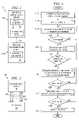
- FIG. 1is a block diagram illustrating one embodiment of a communication network that includes a modifying communication device that may be calibrated;
- FIG. 2is a block diagram illustrating one embodiment of a system that includes a calibrator operable to perform a calibration process
- FIG. 3is a flowchart illustrating one embodiment of a method for performing a calibration process that may be used by the calibrator of FIG. 2 .
- FIGS. 1 through 3 of the drawingslike numerals being used for like and corresponding parts of the various drawings.
- FIG. 1is a block diagram illustrating one embodiment of a communication network 10 that includes a modifying communication device 20 a that may be calibrated according to a calibration process.
- modifying communication device 20 aapplies a diversity parameter adjustment to signals, and transmits the signals to feedback communication device 20 b through multiple antenna elements.
- Modifying communication device 20 adetermines a next diversity parameter adjustment in accordance with the feedback information that describes the signals as received by feedback communication device 20 b .
- a calibration processmay be performed to establish calibration data that may be used to calibrate modifying communication device 20 a.
- network 10operates to provide services such as communication sessions.
- a communication sessionmay refer to an active communication between endpoints, measured from endpoint to endpoint.
- Informationis communicated during a communication session.
- Informationmay refer to voice, data, text, audio, video, multimedia, control, signaling, other information, or any combination of the preceding.
- a packetmay comprise a bundle of data organized in a specific way for transmission, and a frame may comprise the payload of one or more packets organized in a specific way for transmission.
- a packet-based communication protocolsuch as the Internet Protocol (IP) may be used to communicate the packets.
- IPInternet Protocol
- a packetmay comprise any suitable packet, such as a General Packet Radio Service (GPRS) packet, an Enhanced Data for GSM Evolutions (EDGE) packet, or other suitable packet.
- GPRSGeneral Packet Radio Service
- EDGEEnhanced Data for GSM Evolutions
- Network 10may utilize communication protocols and technologies to provide the communication sessions.
- Example communication protocols and technologiesinclude those set by the Institute of Electrical and Electronics Engineers, Inc. (IEEE) 802.xx, International Telecommunications Union (ITU-T) standards, European Telecommunications Standards Institute (ETSI) standards, Internet Engineering Task Force (IETF) standards, or other standards.
- IEEEInstitute of Electrical and Electronics Engineers, Inc. 802.xx
- ITU-TInternational Telecommunications Union
- ETSIEuropean Telecommunications Standards Institute
- IETFInternet Engineering Task Force
- Network 10may use any suitable multiple access technology, for example, a code division multiple access (CDMA) technology.
- CDMAcode division multiple access
- network 10may operate according to a CDMA 2000 telecommunications technology that uses a single CDMA channel.
- a CDMA 2000 high rate data packet technologysuch as the Evolution Data Only (EvDO) technology may be used.
- EvDOEvolution Data Only
- Network 10may comprise any suitable communication network.
- a communication networkmay comprise all or a portion of a public switched telephone network (PSTN), a public or private data network, a local area network (LAN), a metropolitan area network (MAN), a wide area network (WAN), a wireline or wireless network, a local, regional, or global communication network (such as the Internet), an enterprise intranet, other suitable communication link, or any combination of the preceding.
- PSTNpublic switched telephone network
- LANlocal area network
- MANmetropolitan area network
- WANwide area network
- wireline or wireless networksuch as the Internet
- an enterprise intranetsuch as the Internet
- Network 10includes one or more modifying communication devices 20 a and one or more feedback communication devices 20 b that communicate via a link 24 .
- a communication device 20represents any device operable to communicate information via signals with one or more other communication devices 20 .
- communication device 20may comprise a subscriber unit or a base station.
- a subscriber unitmay comprise any device operable to communicate with a base station, for example, a personal digital assistant, a cellular telephone, a mobile handset, a computer, or any other device suitable for communicating signals to and from a base station.
- a subscriber unitmay support, for example, Session Initiation Protocol (SIP) or any other suitable communication protocol.
- SIPSession Initiation Protocol
- a base stationprovides a subscriber unit access to a communication network that allows the subscriber unit to communicate with other networks or devices.
- a base stationtypically includes a base transceiver station and a base station controller.
- the base transceiver stationcommunicates signals to and from one or more subscriber units.
- the base station controllermanages the operation of the base transceiver station.
- Link 24 between communication devices 20 a and 20 bmay include any suitable path operable to communicate one or more channels of signals.
- Link 24may comprise a wireless radio frequency (RF) link or a wired link.
- RFradio frequency
- Modifying communication device 20 amay comprise a transmit diversity communication device.
- a transmit diversity communication devicemay include one or more antenna elements associated with one or more channels.
- An antenna elementis operable to receive, transmit, or both receive and transmit a signal over a channel.
- Multiple antenna elementsmay provide for a separation process known as spatial filtering.
- at least two channelsare simultaneously active in at least one mode of operation.
- Modifying communication device 20 aincludes a signal modifier 28 that modifies one or more signals in accordance with feedback information received from feedback communication device 20 b .
- the modificationmay increase constructive interference or reduce destructive interference.
- signal modifier 28may modify baseband signals prior to conversion to RF signals.
- signal modifier 28may modify RF signals after conversion from baseband signals.
- signal modifier 28modifies the signals according to one or more modification parameter values to adjust one or more diversity parameter values.
- a modification parametermay refer to a feature of signals that may be modulated prior to transmission, and a diversity parameter may refer to a feature describing the signals transmitted after modulation, such as when received by feedback communication device 20 b.
- Signal featuresmay include absolute or relative signal features.
- Absolute signal featuresdescribe a signal with respect to an independent measure, and may include, for example, phase, amplitude, power, frequency, timing, other suitable signal feature, or any combination of the preceding.
- an absolute signal featuremay describe the total power transmitted by modifying communication device 20 a.
- Relative signal featuresdescribe a first signal from a first channel with respect to a second signal from a second channel, and may include, for example, relative power or relative phase.
- signal modifier 28may calculate a diversity parameter adjustment from feedback information according to a diversity control technique.
- the diversity parameter adjustmentmay be calculated from a previous diversity parameter adjustment and a diversity parameter increment, where the diversity parameter increment is determined using feedback information.
- Feedback informationmay be obtained in any suitable manner.
- signal modifier 28obtains feedback information from a quality indication signal received from feedback communication device 20 b .
- a quality indication signalmay refer to a signal that describes a quality of the signal as received by feedback communication device 20 b .
- a quality indication signalmay indicate, whether modifying communication device 20 a should increase or reduce transmission power.
- signal modifier 28obtains feedback information from a control signal generated by a baseband subsystem of modifying communication device 20 a .
- a control signalmay refer to a signal that provides instructions to a component of a communication device.
- the baseband subsystemextracts feedback information from a quality indication signal from feedback communication device 20 b , and generates a control signal that reflects the feedback information.
- the control signalmay provide instructions on whether to increase or reduce transmission power in accordance with the feedback information.
- the operating conditions of modifying communication device 20 amay affect the diversity parameter adjustment, which in turn may affect the diversity parameter values of the signals received at feedback communication device 20 b .
- Operating conditionsmay refer to any aspect of operation of modification communication device 20 a , and may be represented by values of condition parameters, such as temperature, channel frequency, other condition, or other suitable combination of the preceding.
- Signal modifier 28includes calibration data 32 that describes modification parameter values that yield specific diversity parameter values, and may take into account the operating conditions of modifying communication device 20 a .
- Calibration data 32may include diversity parameter data that associates diversity parameter values with modification parameter values that yield the diversity parameter values. The associations may take into account the operating conditions, and specific associations may be defined for specific conditions.
- Calibration data 32may include adjustment data that specifies adjustments to modification parameter values. The adjustments may take into account the operating conditions, and specific adjustments may be defined for specific conditions.
- Calibration data 32may be organized in any suitable manner.
- tablesmay be used to organize the data. For example, different tables may be used for different diversity parameters, or different tables may be used for different operating conditions. Data from one or more tables may be used to calculate a diversity parameter adjustment, and data from multiple tables may be combined in any suitable manner for the calculation.
- diversity parameter datamay specify modification parameter values for absolute transmit power and relative phase.
- Diversity parameter datamay specify the channel power for each channel that yields a particular total transmit power.
- Channel powermay refer to the power transmitted by an antenna element of a channel.
- the absolute transmit powermay refer to the total power transmitted by the active antenna elements, and may be selected in accordance with an air interface standard.
- diversity parameter datamay specify that the channel power for each channel is P/n, where P represents the absolute transmit power, and n represents the number of active channels.
- diversity parameter datamay specify modification parameter values that yield certain particular phase difference values, given particular power ratio values.
- a table i for a power ratio value R(i)may provide modification parameter values that yield phase difference values ⁇ (i,j), where ⁇ (i,j) ranges from 0 to 360 degrees.
- Different tablesmay include modification parameter values for the same or different diversity parameter values.
- different tablesmay apply to different operating conditions, for example, different tables may apply for different frequencies and temperatures.
- adjustment datamay specify adjustments to account for power ratio changes in response to operating conditions.
- a temperature tablespecifies adjustments for temperature variations
- a frequency tablespecifies adjustments for frequency variations. Data from the tables may be combined in any suitable manner, for example, an adjustment from the temperature table may be added to an adjustment from the frequency table to yield an adjustment for the power ratio.
- a power ratiois determined from the feedback information according to a diversity parameter technique. Adjustment data tables corresponding to the current operating conditions are used to determine an adjustment for the power ratio. The adjustment may be added to the power ratio to adjust the power ratio. A table for the power ratio value is used to establish modification parameter values that yield a desired phase difference value.
- calibration datamay be applied even if error is introduced into the calibrated diversity adjustment.
- the calibrated diversity adjustment for point Nis ⁇ (N)
- the calibrated diversity adjustment for point N+1is ⁇ (N+1).
- An error ⁇is introduced into the calibrated diversity adjustment, so the actual diversity adjustment for a point N is ⁇ (N)+ ⁇ (N), and the calibrated diversity adjustment for a point N+1 is ⁇ (N+1)+ ⁇ (N+1).
- the calibrated diversity adjustment from point N to N+1is ⁇ (N+1) ⁇ (N)
- the actual diversity adjustment from point N to N+1is ⁇ (N+1) ⁇ (N)+ ⁇ (N,N+1). If the error is sufficiently small, then the calibration data may be applied.
- Feedback communication device 20 bincludes a feedback generator 30 that generates feedback information that reflects the quality of the modified signals.
- the qualitymay be determined using any suitable measurements, for example, transmit gain, signal-to-noise ratio (SNR), bit error rate (BER), frame error rate (FER), other measurement, or any suitable combination of the preceding.
- SNRsignal-to-noise ratio
- BERbit error rate
- FERframe error rate
- the feedback informationmay be sent to modifying communication device 20 a in a quality indication signal.
- a component of network 10may include logic, an interface, memory, other component, or any suitable combination of the preceding.
- Logicmay refer to hardware, software, other logic, or any suitable combination of the preceding. Certain logic may manage the operation of a device, and may comprise, for example, a processor.
- Interfacemay refer to logic of a device operable to receive input for the device, send output from the device, perform suitable processing of the input or output or both, or any combination of the preceding, and may comprise one or more ports, conversion software, or both.
- Memorymay refer to logic operable to store and facilitate retrieval of information, and may comprise Random Access Memory (RAM), Read Only Memory (ROM), a magnetic drive, a disk drive, a Compact Disk (CD) drive, a Digital Video Disk (DVD) drive, removable media storage, any other suitable data storage medium, or a combination of any of the preceding.
- RAMRandom Access Memory
- ROMRead Only Memory
- CDCompact Disk
- DVDDigital Video Disk
- eachrefers to each member of a set or each member of a subset of a set.
- a subset of a setmay include none, some, or all elements of the set.
- FIG. 2is a block diagram illustrating one embodiment of a system 50 that includes a calibrator 64 operable to perform a calibration process. According to the illustrated embodiment, calibrator 64 generates calibration data for communication device 62 .
- system 50includes calibrator 64 coupled to communication device 62 by a communication bus 66 .
- communication device 62may comprise a transmit diversity device.
- Communication device 62transmits signals through a plurality of channels 68 .
- a channelmay comprise a wireless radio frequency (RF) channel or a wired channel.
- RFradio frequency
- Calibrator 64performs a calibration process to generate calibration data for communication device 62 .
- the calibration processmay be performed online in real time or offline in batch mode.
- Calibrator 64may perform the calibration process according to any suitable method, for example, the method described with respect to FIG. 3 .
- Communication bus 66communicates information between calibrator 64 and communication device 62 .
- Communication bus 66may comprise any suitable communication link, for example, a general purpose interface bus (GPIB), universal serial bus (USB), Ethernet interface, or recommended standard 232C (RS 232) interface.
- GPSgeneral purpose interface bus
- USBuniversal serial bus
- Ethernet interfaceor recommended standard 232C
- a component of system 50may include logic, an interface, memory, other component, or any suitable combination of the preceding that may be integrated or separated according to particular needs. If any of the components of system 50 are separated, the separated components may be coupled using a bus or other suitable link.
- system 50may be integrated or separated according to particular needs. Moreover, the operations of system 50 may be performed by more, fewer, or other modules. Additionally, operations of calibration system 50 may be performed using any suitable logic.
- FIG. 3is a flowchart illustrating one embodiment of a method for performing a calibration process that may be used by calibrator 64 of FIG. 2 .
- Calibrator 64performs the calibration process to generate calibration data for communication device 62 .
- the methodstarts at step 110 , where calibrator 64 instructs communication device 62 to send signals.
- the instructionsmay specify, for example, diversity parameter values and modification parameter values.
- Calibrator 64may send the instructions at the initial stages of the method or may send the instructions throughout the method. Moreover, calibrator 64 may adjust the instructions in accordance with signals sent by communication device 62 .
- Calibrator 64performs various measurements of the signals to generate calibration data comprising calibration tables. Any suitable measurements may be performed, for example, measurements of absolute and relative signal features.
- a signal modifiermay separately modify an I-channel signal according to a real weight and a Q-channel signal according to an imaginary weight. Signals from the channels are summed to yield a combined modified signal.
- the I-channel and Q-channelmay be measured separately. The I-channel may be measured when there is no Q-channel output, and the Q-channel may be measured when there is no I-channel output.
- n I +n Q measurementsmay be taken.
- Steps 118 through 130describe the generation of tables that specify adjustments to account for power ratio changes in response to one or more operating conditions, for example, temperature and frequency.
- the power ratiois measured at a value of an operating condition at step 118 .
- the power ratiomay be measured at a particular temperature value. If there is a next value of the operating condition at step 122 , the method returns to step 118 to measure the power ratio at the next value. If there is no next value at step 122 , the method proceeds to step 126 .
- Calibrator 64establishes a table that specifies adjustments to account for power ratio changes in response to the operating condition at step 126 . There may be a next operating condition, for example, frequency at step 130 . If there is a next operating condition at step 130 , the method returns to step 118 to measure the power ratio at a value of the next operating condition. If there is no next operating condition at step 130 , the method proceeds to step 134 .
- Steps 134 through 146describe the generation of tables that specify modification parameter values for different phase difference values, given particular power ratio values.
- Modification parameter values for a phase difference valueare established at step 134 .
- the modification parameter values for a phase difference valuemay be established by determining the modification parameter values that yield the phase difference value. If there is a next phase difference value at step 138 , the method returns to step 134 to establish the modification parameter values for the next phase difference value. If there is no next phase difference value at step 138 , the method proceeds to step 142 .
- a table describing the modification parameter values for the phase difference values, given the power ratio value,is generated at step 142 . If there is a next power ratio value at step 146 , the method returns to step 134 to establish the modification parameter values for a phase difference value, given the next power ratio value. If there is no next power ratio value at step 146 , the method proceeds to step 150 .
- Calibrator 64provides results from the calibration process at step 150 .
- Calibrator 64may provide results to communication device 62 in real time or in batch mode.
- a technical advantage of one embodimentmay be that a calibration process may be performed on a transmit diversity device to determine calibration data.
- the calibration datamay be used to establish modification parameter values that yield specific diversity parameter values under actual operating conditions.
Landscapes
- Engineering & Computer Science (AREA)
- Computer Networks & Wireless Communication (AREA)
- Signal Processing (AREA)
- Physics & Mathematics (AREA)
- Electromagnetism (AREA)
- Quality & Reliability (AREA)
- Radio Transmission System (AREA)
Abstract
Description
R12[db]=10*log 10(|P1/P2|)
where R12represents the power ratio, P1represents the power of the first signal, and P2represents the power of the second signal.
ΔΦ=Φ1−Φ2
where ΔΦ represents the phase difference, Φ1represents the phase of the first signal, and Φ1represents the phase of the second signal.
Claims (18)
Priority Applications (1)
| Application Number | Priority Date | Filing Date | Title |
|---|---|---|---|
| US11/283,250US7633905B1 (en) | 2005-09-02 | 2005-11-18 | Calibrating a transmit diversity communication device |
Applications Claiming Priority (2)
| Application Number | Priority Date | Filing Date | Title |
|---|---|---|---|
| US71397605P | 2005-09-02 | 2005-09-02 | |
| US11/283,250US7633905B1 (en) | 2005-09-02 | 2005-11-18 | Calibrating a transmit diversity communication device |
Publications (1)
| Publication Number | Publication Date |
|---|---|
| US7633905B1true US7633905B1 (en) | 2009-12-15 |
Family
ID=41403307
Family Applications (2)
| Application Number | Title | Priority Date | Filing Date |
|---|---|---|---|
| US11/283,250Active2027-12-02US7633905B1 (en) | 2005-09-02 | 2005-11-18 | Calibrating a transmit diversity communication device |
| US11/424,257Expired - Fee RelatedUS7885618B1 (en) | 2005-09-02 | 2006-06-15 | Generating calibration data for a transmit diversity communication device |
Family Applications After (1)
| Application Number | Title | Priority Date | Filing Date |
|---|---|---|---|
| US11/424,257Expired - Fee RelatedUS7885618B1 (en) | 2005-09-02 | 2006-06-15 | Generating calibration data for a transmit diversity communication device |
Country Status (1)
| Country | Link |
|---|---|
| US (2) | US7633905B1 (en) |
Cited By (6)
| Publication number | Priority date | Publication date | Assignee | Title |
|---|---|---|---|---|
| US20090054093A1 (en)* | 2007-08-15 | 2009-02-26 | Qualcomm Incorporated | Antenna switching and uplink sounding channel measurement |
| US20100015928A1 (en)* | 2008-07-15 | 2010-01-21 | Sony Corporation | Wireless communication apparatus, wireless communication method, and computer program |
| WO2013022723A1 (en) | 2011-08-05 | 2013-02-14 | Google Inc. | Method and apparatus for adaptive reduction of interference in a small cell of a mobile telecommunication system |
| WO2013026001A1 (en)* | 2011-08-18 | 2013-02-21 | Qualcomm Incorporated | Systems and methods of device calibration |
| US20130259147A1 (en)* | 2009-07-21 | 2013-10-03 | Via Telecom, Inc. | Reverse link mobile transmit diversity |
| CN107769867A (en)* | 2016-08-15 | 2018-03-06 | 中兴通讯股份有限公司 | A kind of physical quantity indicating means, device, system and physical quantity instruction equipment |
Families Citing this family (3)
| Publication number | Priority date | Publication date | Assignee | Title |
|---|---|---|---|---|
| US9214718B2 (en)* | 2012-03-08 | 2015-12-15 | Apple Inc. | Methods for characterizing tunable radio-frequency elements |
| US9084288B2 (en)* | 2013-03-14 | 2015-07-14 | Qualcomm Incorporated | Dual-SIM wireless communications device and method for mitigating receiver desense in dual-active operation |
| CN108536438B (en)* | 2018-04-10 | 2021-11-09 | 武汉斗鱼网络科技有限公司 | Dotting module, method and computer readable medium for processing user behavior data |
Citations (48)
| Publication number | Priority date | Publication date | Assignee | Title |
|---|---|---|---|---|
| US5546090A (en)* | 1991-12-12 | 1996-08-13 | Arraycomm, Inc. | Method and apparatus for calibrating antenna arrays |
| US5642353A (en) | 1991-12-12 | 1997-06-24 | Arraycomm, Incorporated | Spatial division multiple access wireless communication systems |
| WO1997024818A1 (en) | 1995-12-28 | 1997-07-10 | Qualcomm Incorporated | Method and apparatus for providing antenna diversity in a portable radiotelephone |
| JPH09238098A (en) | 1995-07-19 | 1997-09-09 | Nec Corp | Fdd/cdma transmission reception system |
| US5832044A (en) | 1996-09-27 | 1998-11-03 | Elvino S. Sousa | Transmitter antenna diversity and fading-resistant modulation for wireless communication systems |
| US5991330A (en) | 1997-06-27 | 1999-11-23 | Telefonaktiebolaget L M Ericsson (Pub1) | Mobile Station synchronization within a spread spectrum communication systems |
| US5999826A (en) | 1996-05-17 | 1999-12-07 | Motorola, Inc. | Devices for transmitter path weights and methods therefor |
| EP0986193A1 (en) | 1998-08-14 | 2000-03-15 | Ascom Systec AG | Method and circuit arrangement for compensating errors during adjustment of combining coefficients of a diversity circuit |
| JP2000151484A (en) | 1998-11-06 | 2000-05-30 | Lucent Technol Inc | Space-time diversity for radio system |
| WO2000079701A1 (en) | 1999-06-18 | 2000-12-28 | Nokia Corporation | Diversity transmission method and system |
| US6185440B1 (en) | 1997-12-10 | 2001-02-06 | Arraycomm, Inc. | Method for sequentially transmitting a downlink signal from a communication station that has an antenna array to achieve an omnidirectional radiation |
| GB2353437A (en) | 1999-08-17 | 2001-02-21 | Fujitsu Ltd | Diversity transmission means with phase adjustment depending upon a feedback signal supplied to the transmitter by the receiver |
| US6226509B1 (en) | 1998-09-15 | 2001-05-01 | Nortel Networks Limited | Image reject mixer, circuit, and method for image rejection |
| US6236363B1 (en) | 1998-01-30 | 2001-05-22 | Micronetics Wireless | Smart antenna channel simulator and test system |
| WO2001069814A1 (en) | 2000-03-15 | 2001-09-20 | Nokia Corporation | Transmit diversity method and system |
| US6330294B1 (en) | 1997-07-14 | 2001-12-11 | Cselt- Centro Studi E Laboratori Telecomuniicazioni S.P.A. | Method of and apparatus for digital radio signal reception |
| US6343218B1 (en) | 1998-01-16 | 2002-01-29 | Ntt Docomo Inc. | Transmission power control method, mobile phone, base station, and recording medium |
| US6392988B1 (en) | 1999-09-13 | 2002-05-21 | Lucent Technologies Inc. | Transmitter architecture employing space time spreading and orthogonal transmit diversity techniques |
| US6480153B1 (en)* | 2001-08-07 | 2002-11-12 | Electronics And Telecommunications Research Institute | Calibration apparatus of adaptive array antenna and calibration method thereof |
| EP1262031A1 (en) | 2000-02-26 | 2002-12-04 | Robert Bosch Gmbh | Method and system for transmitting data, with transmission antenna diversity |
| US6492942B1 (en) | 1999-11-09 | 2002-12-10 | Com Dev International, Inc. | Content-based adaptive parasitic array antenna system |
| EP1282244A1 (en) | 2001-07-30 | 2003-02-05 | Lucent Technologies Inc. | Symmetric sweep phase sweep transmit diversity |
| EP1282242A1 (en) | 2001-07-30 | 2003-02-05 | Lucent Technologies Inc. | Split shift phase sweep transmit diversity |
| EP1284545A1 (en) | 2001-08-13 | 2003-02-19 | Motorola, Inc. | Transmit diversity wireless communication |
| US20030112880A1 (en) | 2001-05-17 | 2003-06-19 | Walton Jay R. | Method and apparatus for processing data for transmission in a multi-channel communication system using selective channel inversion |
| US6615024B1 (en)* | 1998-05-01 | 2003-09-02 | Arraycomm, Inc. | Method and apparatus for determining signatures for calibrating a communication station having an antenna array |
| US6636495B1 (en) | 1999-06-24 | 2003-10-21 | Alcatel | Diversity transmission in a mobile radio system |
| WO2003090386A1 (en) | 2002-04-19 | 2003-10-30 | Samsung Electronics Canada Inc. | Apparatus and method for calibrating and compensating for distortion of an output signal in a smart antenna |
| US6690952B2 (en)* | 1999-12-15 | 2004-02-10 | Nippon Telegraph & Telephone Corporation | Adaptive array antenna transceiver apparatus |
| US6704370B1 (en) | 1998-10-09 | 2004-03-09 | Nortel Networks Limited | Interleaving methodology and apparatus for CDMA |
| US20040048584A1 (en) | 2002-09-10 | 2004-03-11 | Chandra Vaidyanathan | Techniques for correcting for phase and amplitude offsets in a MIMO radio device |
| US20040085239A1 (en) | 2002-08-09 | 2004-05-06 | Masato Ukena | Array antenna apparatus utilizing a nonlinear distortion compensator circuit |
| WO2004045108A1 (en) | 2002-11-11 | 2004-05-27 | Huawei Technologies Co., Ltd. | Method for implementing a function of closed loop transmitting diversity on the dedicated channel |
| US6745009B2 (en) | 2002-05-15 | 2004-06-01 | Nokia Corporation | Apparatus, and associated method, for facilitating antenna weight selection utilizing deterministic perturbation gradient approximation |
| US6762717B2 (en)* | 2001-09-17 | 2004-07-13 | Nec Corporation | Apparatus and method for calibrating array antenna |
| US6810264B1 (en) | 1999-11-16 | 2004-10-26 | Samsung Electronics Co., Ltd. | Power controlling apparatus and method in mobile communication system |
| US6859643B1 (en) | 2000-08-04 | 2005-02-22 | Lucent Technologies Inc. | Power amplifier sharing in a wireless communication system with amplifier pre-distortion |
| US20050059355A1 (en) | 2003-09-17 | 2005-03-17 | Accton Technology Corporation | System and method for multi-path simulation |
| US6882228B2 (en) | 2003-09-08 | 2005-04-19 | Broadcom Corp. | Radio frequency integrated circuit having an antenna diversity structure |
| US20050143113A1 (en) | 2002-02-18 | 2005-06-30 | Lee Young J. | Method for transmitting power control bits and detecting power control rate |
| US6917786B1 (en)* | 1999-11-24 | 2005-07-12 | Nec Corporation | Wireless receiver and method of calibration thereof |
| WO2005081444A1 (en) | 2004-02-13 | 2005-09-01 | Telefonaktiebolaget Lm Ericsson (Publ) | Adaptive feedback for mimo communication systems |
| US7027523B2 (en)* | 2001-06-22 | 2006-04-11 | Qualcomm Incorporated | Method and apparatus for transmitting data in a time division duplexed (TDD) communication system |
| US20060160496A1 (en) | 2003-07-02 | 2006-07-20 | Matsushita Electic Industrial Co., Ltd. | Communication apparatus and communication method |
| US7197282B2 (en) | 2001-07-26 | 2007-03-27 | Ericsson Inc. | Mobile station loop-back signal processing |
| US20070189151A1 (en) | 2006-02-10 | 2007-08-16 | Interdigital Technology Corporation | Method and apparatus for performing uplink transmission in a multiple-input multiple-output single carrier frequency division multiple access system |
| US7340248B2 (en)* | 2005-03-30 | 2008-03-04 | Fujitsu Limited | Calibration apparatus |
| US7392015B1 (en)* | 2003-02-14 | 2008-06-24 | Calamp Corp. | Calibration methods and structures in wireless communications systems |
Family Cites Families (4)
| Publication number | Priority date | Publication date | Assignee | Title |
|---|---|---|---|---|
| US20020111142A1 (en) | 2000-12-18 | 2002-08-15 | Klimovitch Gleb V. | System, apparatus, and method of estimating multiple-input multiple-output wireless channel with compensation for phase noise and frequency offset |
| EP1359684A1 (en)* | 2002-04-30 | 2003-11-05 | Motorola Energy Systems Inc. | Wireless transmission using an adaptive transmit antenna array |
| US7333788B2 (en) | 2002-12-20 | 2008-02-19 | Texas Instruments Incorporated | Method for calibrating automatic gain control in wireless devices |
| US20050013059A1 (en) | 2003-07-15 | 2005-01-20 | International Business Machines Corporation | Magnetoresistive sensor with a net magnetic moment |
- 2005
- 2005-11-18USUS11/283,250patent/US7633905B1/enactiveActive
- 2006
- 2006-06-15USUS11/424,257patent/US7885618B1/ennot_activeExpired - Fee Related
Patent Citations (49)
| Publication number | Priority date | Publication date | Assignee | Title |
|---|---|---|---|---|
| US5546090A (en)* | 1991-12-12 | 1996-08-13 | Arraycomm, Inc. | Method and apparatus for calibrating antenna arrays |
| US5642353A (en) | 1991-12-12 | 1997-06-24 | Arraycomm, Incorporated | Spatial division multiple access wireless communication systems |
| JPH09238098A (en) | 1995-07-19 | 1997-09-09 | Nec Corp | Fdd/cdma transmission reception system |
| WO1997024818A1 (en) | 1995-12-28 | 1997-07-10 | Qualcomm Incorporated | Method and apparatus for providing antenna diversity in a portable radiotelephone |
| US5999826A (en) | 1996-05-17 | 1999-12-07 | Motorola, Inc. | Devices for transmitter path weights and methods therefor |
| US5832044A (en) | 1996-09-27 | 1998-11-03 | Elvino S. Sousa | Transmitter antenna diversity and fading-resistant modulation for wireless communication systems |
| US5991330A (en) | 1997-06-27 | 1999-11-23 | Telefonaktiebolaget L M Ericsson (Pub1) | Mobile Station synchronization within a spread spectrum communication systems |
| US6330294B1 (en) | 1997-07-14 | 2001-12-11 | Cselt- Centro Studi E Laboratori Telecomuniicazioni S.P.A. | Method of and apparatus for digital radio signal reception |
| US6185440B1 (en) | 1997-12-10 | 2001-02-06 | Arraycomm, Inc. | Method for sequentially transmitting a downlink signal from a communication station that has an antenna array to achieve an omnidirectional radiation |
| US6343218B1 (en) | 1998-01-16 | 2002-01-29 | Ntt Docomo Inc. | Transmission power control method, mobile phone, base station, and recording medium |
| US6236363B1 (en) | 1998-01-30 | 2001-05-22 | Micronetics Wireless | Smart antenna channel simulator and test system |
| US6615024B1 (en)* | 1998-05-01 | 2003-09-02 | Arraycomm, Inc. | Method and apparatus for determining signatures for calibrating a communication station having an antenna array |
| EP0986193A1 (en) | 1998-08-14 | 2000-03-15 | Ascom Systec AG | Method and circuit arrangement for compensating errors during adjustment of combining coefficients of a diversity circuit |
| US6226509B1 (en) | 1998-09-15 | 2001-05-01 | Nortel Networks Limited | Image reject mixer, circuit, and method for image rejection |
| US6704370B1 (en) | 1998-10-09 | 2004-03-09 | Nortel Networks Limited | Interleaving methodology and apparatus for CDMA |
| JP2000151484A (en) | 1998-11-06 | 2000-05-30 | Lucent Technol Inc | Space-time diversity for radio system |
| WO2000079701A1 (en) | 1999-06-18 | 2000-12-28 | Nokia Corporation | Diversity transmission method and system |
| US6636495B1 (en) | 1999-06-24 | 2003-10-21 | Alcatel | Diversity transmission in a mobile radio system |
| GB2353437A (en) | 1999-08-17 | 2001-02-21 | Fujitsu Ltd | Diversity transmission means with phase adjustment depending upon a feedback signal supplied to the transmitter by the receiver |
| US6392988B1 (en) | 1999-09-13 | 2002-05-21 | Lucent Technologies Inc. | Transmitter architecture employing space time spreading and orthogonal transmit diversity techniques |
| US6492942B1 (en) | 1999-11-09 | 2002-12-10 | Com Dev International, Inc. | Content-based adaptive parasitic array antenna system |
| US6810264B1 (en) | 1999-11-16 | 2004-10-26 | Samsung Electronics Co., Ltd. | Power controlling apparatus and method in mobile communication system |
| US6917786B1 (en)* | 1999-11-24 | 2005-07-12 | Nec Corporation | Wireless receiver and method of calibration thereof |
| US6690952B2 (en)* | 1999-12-15 | 2004-02-10 | Nippon Telegraph & Telephone Corporation | Adaptive array antenna transceiver apparatus |
| EP1262031A1 (en) | 2000-02-26 | 2002-12-04 | Robert Bosch Gmbh | Method and system for transmitting data, with transmission antenna diversity |
| WO2001069814A1 (en) | 2000-03-15 | 2001-09-20 | Nokia Corporation | Transmit diversity method and system |
| US7200368B1 (en)* | 2000-03-15 | 2007-04-03 | Nokia Corporation | Transmit diversity method and system |
| US6859643B1 (en) | 2000-08-04 | 2005-02-22 | Lucent Technologies Inc. | Power amplifier sharing in a wireless communication system with amplifier pre-distortion |
| US20030112880A1 (en) | 2001-05-17 | 2003-06-19 | Walton Jay R. | Method and apparatus for processing data for transmission in a multi-channel communication system using selective channel inversion |
| US7027523B2 (en)* | 2001-06-22 | 2006-04-11 | Qualcomm Incorporated | Method and apparatus for transmitting data in a time division duplexed (TDD) communication system |
| US7197282B2 (en) | 2001-07-26 | 2007-03-27 | Ericsson Inc. | Mobile station loop-back signal processing |
| EP1282242A1 (en) | 2001-07-30 | 2003-02-05 | Lucent Technologies Inc. | Split shift phase sweep transmit diversity |
| EP1282244A1 (en) | 2001-07-30 | 2003-02-05 | Lucent Technologies Inc. | Symmetric sweep phase sweep transmit diversity |
| US6480153B1 (en)* | 2001-08-07 | 2002-11-12 | Electronics And Telecommunications Research Institute | Calibration apparatus of adaptive array antenna and calibration method thereof |
| EP1284545A1 (en) | 2001-08-13 | 2003-02-19 | Motorola, Inc. | Transmit diversity wireless communication |
| US6762717B2 (en)* | 2001-09-17 | 2004-07-13 | Nec Corporation | Apparatus and method for calibrating array antenna |
| US20050143113A1 (en) | 2002-02-18 | 2005-06-30 | Lee Young J. | Method for transmitting power control bits and detecting power control rate |
| WO2003090386A1 (en) | 2002-04-19 | 2003-10-30 | Samsung Electronics Canada Inc. | Apparatus and method for calibrating and compensating for distortion of an output signal in a smart antenna |
| US6745009B2 (en) | 2002-05-15 | 2004-06-01 | Nokia Corporation | Apparatus, and associated method, for facilitating antenna weight selection utilizing deterministic perturbation gradient approximation |
| US20040085239A1 (en) | 2002-08-09 | 2004-05-06 | Masato Ukena | Array antenna apparatus utilizing a nonlinear distortion compensator circuit |
| US20040048584A1 (en) | 2002-09-10 | 2004-03-11 | Chandra Vaidyanathan | Techniques for correcting for phase and amplitude offsets in a MIMO radio device |
| WO2004045108A1 (en) | 2002-11-11 | 2004-05-27 | Huawei Technologies Co., Ltd. | Method for implementing a function of closed loop transmitting diversity on the dedicated channel |
| US7392015B1 (en)* | 2003-02-14 | 2008-06-24 | Calamp Corp. | Calibration methods and structures in wireless communications systems |
| US20060160496A1 (en) | 2003-07-02 | 2006-07-20 | Matsushita Electic Industrial Co., Ltd. | Communication apparatus and communication method |
| US6882228B2 (en) | 2003-09-08 | 2005-04-19 | Broadcom Corp. | Radio frequency integrated circuit having an antenna diversity structure |
| US20050059355A1 (en) | 2003-09-17 | 2005-03-17 | Accton Technology Corporation | System and method for multi-path simulation |
| WO2005081444A1 (en) | 2004-02-13 | 2005-09-01 | Telefonaktiebolaget Lm Ericsson (Publ) | Adaptive feedback for mimo communication systems |
| US7340248B2 (en)* | 2005-03-30 | 2008-03-04 | Fujitsu Limited | Calibration apparatus |
| US20070189151A1 (en) | 2006-02-10 | 2007-08-16 | Interdigital Technology Corporation | Method and apparatus for performing uplink transmission in a multiple-input multiple-output single carrier frequency division multiple access system |
Non-Patent Citations (9)
| Title |
|---|
| "Application Note 3434, RF Power Reduction for CDMA/W-CDMA Cellular Phones," Maxim/Dallas, http://www.maxim-ic.com/appnotes.cfm/appnote-number/3434, 4 pages, Dec. 15, 2004. |
| "Model 2800 RF Power Analyzer", Keithley Instruments, Inc., http://www.globalspec.com/FeaturedProducts/Detail/KeithleyInstruments/Model-2800-R, 3 pages, Printed Nov. 14, 2005. |
| "NIMS: Networked Infomechanical Systems", Center for Embedded Networked Sensing, http://research.cens.ucla.edu/portal/nims, 10 pages, Printed Nov. 14, 2005. |
| Brandle, George, "New Testing Requirements for cdma2000 Mobile Phones", Evaluation Engineering, http://www.evaluationengineering.com/archive/articles/0601wire.htm, 9 pages, Printed Nov. 14, 2005. |
| Derryberry et al., "Transmit Diversity in 3G CDMA Systems", Wideband Wireless Access Technologies to Broadband Internet, IEEE Communications Magazine, Apr. 2002, pp. 68-75. |
| Nishimori et al, Automatic Calibration Method Using Transmitting Signals of an Adaptive Array for TDD Systems, IEEE, 5 pages, Nov. 2001.* |
| Non-final Office Action for U.S. Appl. No. 11/424,257 mailed Jun. 10, 2009. |
| Rashid-Farrokhi, et al., "Transmit Beamforming and Power Control for Cellular Wireless Systems", IEEE Journal on Selected Areas in Communications, vol. 16, No. 8, Oct. 1998, pp. 1437-1450. |
| Strickler, Walt, "Saving Time and Money on Mobile Phone Production Testing", Keithley Instruments, Inc., No. 2536, www.keithley.com, 2 pages, Jul. 2004. |
Cited By (11)
| Publication number | Priority date | Publication date | Assignee | Title |
|---|---|---|---|---|
| US20090054093A1 (en)* | 2007-08-15 | 2009-02-26 | Qualcomm Incorporated | Antenna switching and uplink sounding channel measurement |
| US8099132B2 (en)* | 2007-08-15 | 2012-01-17 | Qualcomm Incorporated | Antenna switching and uplink sounding channel measurement |
| US20100015928A1 (en)* | 2008-07-15 | 2010-01-21 | Sony Corporation | Wireless communication apparatus, wireless communication method, and computer program |
| US8180300B2 (en)* | 2008-07-15 | 2012-05-15 | Sony Corporation | Wireless communication apparatus, wireless communication method, and computer program |
| US20130259147A1 (en)* | 2009-07-21 | 2013-10-03 | Via Telecom, Inc. | Reverse link mobile transmit diversity |
| US8699969B2 (en)* | 2009-07-21 | 2014-04-15 | Via Telecom Co., Ltd. | Reverse link mobile transmit diversity |
| WO2013022723A1 (en) | 2011-08-05 | 2013-02-14 | Google Inc. | Method and apparatus for adaptive reduction of interference in a small cell of a mobile telecommunication system |
| WO2013026001A1 (en)* | 2011-08-18 | 2013-02-21 | Qualcomm Incorporated | Systems and methods of device calibration |
| US8868056B2 (en) | 2011-08-18 | 2014-10-21 | Qualcomm Incorporated | Systems and methods of device calibration |
| CN107769867A (en)* | 2016-08-15 | 2018-03-06 | 中兴通讯股份有限公司 | A kind of physical quantity indicating means, device, system and physical quantity instruction equipment |
| CN107769867B (en)* | 2016-08-15 | 2021-06-25 | 中兴通讯股份有限公司 | Physical quantity indicating method, device and system and physical quantity indicating equipment |
Also Published As
| Publication number | Publication date |
|---|---|
| US7885618B1 (en) | 2011-02-08 |
Similar Documents
| Publication | Publication Date | Title |
|---|---|---|
| US9537544B2 (en) | System, method and apparatus for transmit diversity control based on variations in propogation path | |
| US8351882B2 (en) | Amplifying a transmit signal using a fractional power amplifier | |
| US7885618B1 (en) | Generating calibration data for a transmit diversity communication device | |
| US7616930B2 (en) | Determining a phase adjustment in accordance with power trends | |
| US8750811B2 (en) | Method, apparatus and system for phase difference adjustment in transmit diversity | |
| US8351976B2 (en) | Modifying a signal by controlling transmit diversity parameters | |
| US8249528B2 (en) | Method, apparatus and system for providing transmit diversity feedback during soft handoff | |
| CA2628478C (en) | Antenna array calibration for wireless communication systems | |
| KR20080005287A (en) | Antenna Array Calibration for Wireless Communication Systems | |
| WO2007044670A1 (en) | Performing a scan of diversity parameter differences | |
| US20110263213A1 (en) | Amplifying a transmit signal using a fractional power amplifier | |
| JP4903805B2 (en) | Antenna array calibration for multi-input multi-output wireless communication systems | |
| US7835702B1 (en) | Calculating a diversity parameter adjustment according to previously applied diversity parameter adjustments | |
| KR101019394B1 (en) | Antenna Array Calibration for Multiple Input Multiple Output Wireless Communication Systems | |
| JP2012165389A (en) | Antenna array calibration for wireless communication systems |
Legal Events
| Date | Code | Title | Description |
|---|---|---|---|
| AS | Assignment | Owner name:MAGNOLIA BROADBAND INC., NEW JERSEY Free format text:ASSIGNMENT OF ASSIGNORS INTEREST;ASSIGNORS:HAREL, HAIM;KARMI, YAIR;CHEN, PHIL FU-WEI;AND OTHERS;REEL/FRAME:017268/0623 Effective date:20051111 | |
| AS | Assignment | Owner name:VENTURE LENDING & LEASING IV, INC., CALIFORNIA Free format text:SECURITY AGREEMENT;ASSIGNOR:MAGNOLIA BROADBAND, INC.;REEL/FRAME:018235/0083 Effective date:20060822 Owner name:VENTURE LENDING & LEASING IV, INC.,CALIFORNIA Free format text:SECURITY AGREEMENT;ASSIGNOR:MAGNOLIA BROADBAND, INC.;REEL/FRAME:018235/0083 Effective date:20060822 | |
| AS | Assignment | Owner name:ECENTURY CAPITAL PARTNERS, L.P., VIRGINIA Free format text:SECURITY AGREEMENT;ASSIGNOR:MAGNOLIA BROADBAND, INC.;REEL/FRAME:020497/0912 Effective date:20080213 Owner name:SCP PRIVATE EQUITY PARTNERS II, L.P., PENNSYLVANIA Free format text:SECURITY AGREEMENT;ASSIGNOR:MAGNOLIA BROADBAND, INC.;REEL/FRAME:020497/0912 Effective date:20080213 Owner name:SELWAY PARTNERS, LLC, NEW JERSEY Free format text:SECURITY AGREEMENT;ASSIGNOR:MAGNOLIA BROADBAND, INC.;REEL/FRAME:020497/0912 Effective date:20080213 Owner name:DRAPER FISHER JURVETSON GOTHAM VENTURE FUND, L.P., Free format text:SECURITY AGREEMENT;ASSIGNOR:MAGNOLIA BROADBAND, INC.;REEL/FRAME:020497/0912 Effective date:20080213 Owner name:DRAPER FISHER JURVETSON GOTHAM INVESTMENT, LLC, NE Free format text:SECURITY AGREEMENT;ASSIGNOR:MAGNOLIA BROADBAND, INC.;REEL/FRAME:020497/0912 Effective date:20080213 Owner name:GROSVENOR SPECIAL VENTURES IV, LP, DISTRICT OF COL Free format text:SECURITY AGREEMENT;ASSIGNOR:MAGNOLIA BROADBAND, INC.;REEL/FRAME:020497/0912 Effective date:20080213 Owner name:ECENTURY CAPITAL PARTNERS, L.P.,VIRGINIA Free format text:SECURITY AGREEMENT;ASSIGNOR:MAGNOLIA BROADBAND, INC.;REEL/FRAME:020497/0912 Effective date:20080213 Owner name:SCP PRIVATE EQUITY PARTNERS II, L.P.,PENNSYLVANIA Free format text:SECURITY AGREEMENT;ASSIGNOR:MAGNOLIA BROADBAND, INC.;REEL/FRAME:020497/0912 Effective date:20080213 Owner name:SELWAY PARTNERS, LLC,NEW JERSEY Free format text:SECURITY AGREEMENT;ASSIGNOR:MAGNOLIA BROADBAND, INC.;REEL/FRAME:020497/0912 Effective date:20080213 Owner name:DRAPER FISHER JURVETSON GOTHAM INVESTMENT, LLC,NEW Free format text:SECURITY AGREEMENT;ASSIGNOR:MAGNOLIA BROADBAND, INC.;REEL/FRAME:020497/0912 Effective date:20080213 Owner name:GROSVENOR SPECIAL VENTURES IV, LP,DISTRICT OF COLU Free format text:SECURITY AGREEMENT;ASSIGNOR:MAGNOLIA BROADBAND, INC.;REEL/FRAME:020497/0912 Effective date:20080213 | |
| STCF | Information on status: patent grant | Free format text:PATENTED CASE | |
| AS | Assignment | Owner name:MAGNOLIA BROADBAND INC., NEW JERSEY Free format text:RELEASE BY SECURED PARTY;ASSIGNORS:ECENTURY CAPITAL PARTNERS, L.P.;SCP PRIVATE EQUITY PARTNERS II, L.P.;SELWAY PARTNERS, LLC;AND OTHERS;REEL/FRAME:027946/0357 Effective date:20090807 | |
| AS | Assignment | Owner name:MAGNOLIA BROADBAND INC., NEW JERSEY Free format text:RELEASE BY SECURED PARTY;ASSIGNOR:VENTURE LENDING & LEASING IV, INC.;REEL/FRAME:027953/0375 Effective date:20090717 | |
| AS | Assignment | Owner name:GOOGLE INC., CALIFORNIA Free format text:ASSIGNMENT OF ASSIGNORS INTEREST;ASSIGNOR:MAGNOLIA BROADBAND, INC.;REEL/FRAME:028251/0856 Effective date:20120330 | |
| FEPP | Fee payment procedure | Free format text:PAT HOLDER NO LONGER CLAIMS SMALL ENTITY STATUS, ENTITY STATUS SET TO UNDISCOUNTED (ORIGINAL EVENT CODE: STOL); ENTITY STATUS OF PATENT OWNER: LARGE ENTITY | |
| REFU | Refund | Free format text:REFUND - SURCHARGE, PETITION TO ACCEPT PYMT AFTER EXP, UNINTENTIONAL (ORIGINAL EVENT CODE: R2551); ENTITY STATUS OF PATENT OWNER: LARGE ENTITY | |
| FPAY | Fee payment | Year of fee payment:4 | |
| FPAY | Fee payment | Year of fee payment:8 | |
| AS | Assignment | Owner name:GOOGLE LLC, CALIFORNIA Free format text:CHANGE OF NAME;ASSIGNOR:GOOGLE INC.;REEL/FRAME:044101/0610 Effective date:20170929 | |
| MAFP | Maintenance fee payment | Free format text:PAYMENT OF MAINTENANCE FEE, 12TH YEAR, LARGE ENTITY (ORIGINAL EVENT CODE: M1553); ENTITY STATUS OF PATENT OWNER: LARGE ENTITY Year of fee payment:12 |