US7633388B2 - Method and apparatus for interfacing security systems by periodic check in with remote facility - Google Patents
Method and apparatus for interfacing security systems by periodic check in with remote facilityDownload PDFInfo
- Publication number
- US7633388B2 US7633388B2US11/858,252US85825207AUS7633388B2US 7633388 B2US7633388 B2US 7633388B2US 85825207 AUS85825207 AUS 85825207AUS 7633388 B2US7633388 B2US 7633388B2
- Authority
- US
- United States
- Prior art keywords
- security system
- security
- remote facility
- user
- periodically updated
- Prior art date
- Legal status (The legal status is an assumption and is not a legal conclusion. Google has not performed a legal analysis and makes no representation as to the accuracy of the status listed.)
- Expired - Lifetime
Links
- 238000000034methodMethods0.000titleclaimsdescription13
- 230000000737periodic effectEffects0.000titledescription5
- 230000006854communicationEffects0.000claimsdescription27
- 238000004891communicationMethods0.000claimsdescription27
- 230000004044responseEffects0.000claimsdescription8
- 238000012790confirmationMethods0.000claimsdescription2
- 238000013459approachMethods0.000description11
- 238000012544monitoring processMethods0.000description10
- 230000008859changeEffects0.000description8
- 230000005540biological transmissionEffects0.000description7
- 230000033001locomotionEffects0.000description7
- 238000012545processingMethods0.000description5
- 230000008569processEffects0.000description4
- 230000009471actionEffects0.000description3
- 230000008901benefitEffects0.000description3
- 238000012423maintenanceMethods0.000description3
- 230000001960triggered effectEffects0.000description3
- 230000006399behaviorEffects0.000description2
- 238000004378air conditioningMethods0.000description1
- 230000004075alterationEffects0.000description1
- 230000007175bidirectional communicationEffects0.000description1
- 230000001413cellular effectEffects0.000description1
- 230000001934delayEffects0.000description1
- 230000006870functionEffects0.000description1
- 239000011521glassSubstances0.000description1
- 238000010438heat treatmentMethods0.000description1
- 230000000977initiatory effectEffects0.000description1
- 230000007257malfunctionEffects0.000description1
- 238000012986modificationMethods0.000description1
- 230000004048modificationEffects0.000description1
- 230000002093peripheral effectEffects0.000description1
- 230000011664signalingEffects0.000description1
- 239000002341toxic gasSubstances0.000description1
- 238000011144upstream manufacturingMethods0.000description1
Images


Classifications
- G—PHYSICS
- G08—SIGNALLING
- G08B—SIGNALLING OR CALLING SYSTEMS; ORDER TELEGRAPHS; ALARM SYSTEMS
- G08B25/00—Alarm systems in which the location of the alarm condition is signalled to a central station, e.g. fire or police telegraphic systems
- G08B25/009—Signalling of the alarm condition to a substation whose identity is signalled to a central station, e.g. relaying alarm signals in order to extend communication range
Definitions
- the inventionrelates generally to security systems and, more particularly, to interfacing security systems so that they communicate with one another.
- Security systemssuch as for homes and businesses, have become commonplace as people seek to protect themselves and their property.
- Security systemstypically employ sensors at entry points, such as windows and doors, along with interior sensors such as motion detectors and glass break detectors. The user arms and disarms the system typically by entering a password on a keypad.
- the security systemmay include a telephone dialer for informing a remote monitoring station of an alarm condition.
- the present inventiondescribes a solution that allows security systems to interface with one another to obtain periodically updated information.
- the inventionenables a user to stand at the user interface, such as a keypad, of a security system and control the user interface, such as by selecting an icon, to view the information from the interface of another, remote security system as if the user was standing in front of the other interface. For example, if the user had two homes, the user could select an icon from the interface of the first home's security system to virtually jump to the interface of the second home's security system. Furthermore, the user can send a command via the first home's security system to the second home's security system.
- a remote facilityacts as an intermediary by periodically receiving updates from the security systems so the information is readily available.
- a security apparatusin one aspect of the invention, includes a user interface device in a first security system, where the first security system secures a first building location and the user interface device is capable of providing information regarding the first security system to a user.
- a receiveris provided for receiving, from a remote facility, periodically updated information regarding a second security system that secures a second building location different than the first building location. The periodically updated information is transmitted to the remote facility by the second security system according to an update interval of the second security system, and the user interface device is responsive to the receiver and the periodically updated information for providing information regarding the second security system to the user.
- a remote facilitywhich is remote from a first security system that secures a first building location, and a second security system that secures a second building location different than the first building location, includes a receiver for receiving periodically updated information from a first security system that secures a first building location, where the periodically updated information is transmitted from the first security system to the receiver, according to an update interval of the first security system.
- a controlis provided for recovering the periodically updated information from the receiver.
- a transmitteris associated with the control for transmitting the periodically updated information to a second security system that secures a second building location different than the first building location.
- the second security systemprovides information regarding the first security system to a user via a user interface device in the second security system, according to the periodically updated information.
- a security apparatusin yet another aspect of the invention, includes a user interface device in a first security system, where the first security system secures a first building location, and the user interface device receives a request by a user to establish two-way voice communication between the first security system and a second security system that secures a second building location different than the first building location.
- a controlis associated with the user interface device for handling the request by the user.
- a transmitteris associated with the control that is responsive to the request by the user for transmitting a signal to a remote facility to cause the remote facility to communicate with the second security system to establish the two-way voice communication between the first security system and the second security system, via the remote facility.
- a method for providing security system related data to a personal computerincludes running a web browser on the personal computer to connect to a designated web site to request information regarding at least a first security system that secures at least a first building location.
- a remote facilityreceives periodically updated information from the at least a first security system according to an update interval of the at least a first security system, and the web site has access to the periodically updated information.
- the methodfurther includes displaying the information regarding the at least a first security system to the user, via the web browser, responsive to the request and the periodically updated information.
- FIG. 1illustrates an overview of an example security system, according to the invention
- FIG. 2illustrates an arrangement with two security systems, a personal computer, and a remote facility, according to the invention
- FIG. 3illustrates a remote facility, according to the invention
- FIG. 4illustrates a method used by a security system, according to the invention
- FIG. 5illustrates a method used by a remote facility, according to the invention
- FIG. 6illustrates an example user interface that allows a user to select a location, according to the invention
- FIG. 7illustrates an example user interface displaying information regarding a selected location, according to the invention
- FIG. 8illustrates an example user interface that allows a user to change a status, according to the invention.
- FIG. 9illustrates an example user interface that allows a user to enter a pass code, according to the invention.
- FIG. 1illustrates an overview of an example security system, according to the invention.
- the security system 100includes a central control panel 110 that communicates with a number of sensors via a wired or wireless path.
- the wireless pathmay be an RF path, for instance.
- the control panel 110may receive signals from motion sensors 125 that detect when a person enters a room. Signals received from fire sensors 130 indicate that a fire has been detected. Signals received from window and door sensors 135 indicate that a window or door has been opened.
- Signals received from a peripheral user interface device 140may arm and disarm the system.
- the user interface device 140may be the primary interface between the human user and the security system 100 .
- the user interface device 140may include components that are analogous to the control panel 110 , including a control, memory and power source.
- the user interface device 140includes a transceiver (transmitter and receiver).
- the user interface device 140is commonly provided in the home such as by affixing it to a wall or placing it on a table, for instance, while the control panel 110 generally is a larger component that maybe installed, e.g., in a closet or basement.
- the user interface device 140is integrated into the control panel 110 .
- control panel 110may communicate with various other components, such as a wireless key fob/panic button that is used to trip an alarm.
- the control panel 110may also transmit signals to components of the security system 100 . For example, signals may be transmitted to a siren 120 to activate the siren when an alarm condition is detected. Signals may be sent to the user interface device 140 to display status information to the user, such as whether the system is armed or disarmed, whether a specific door or window has been opened, and, when the system is armed, whether an alarm has been tripped.
- the control panel 110may also have the ability to notify local emergency services and/or a remote monitoring station of an alarm condition via a telephone dialer 122 .
- a telephone network interface 124such as a modem, allows the control panel 110 to send and receive information via a telephone link.
- the functionality of the dialer 122may be combined into the interface 124 .
- a computer network interface 126allows the control panel 110 to send and receive information via a computer network, such as the Internet.
- the computer network interface 126may include an always-on interface, such as a DSL or cable modern, and a network interface card, for example. Or, a dial-up telephone connection may be used. Other communication paths such as long-range radio and a cellular telephone link may also be used.
- the dialer 122 and interfaces 124 and 126are typically hardwired to the control panel 110 and activated by the control 114 .
- One or more cameras 128may be used to provide image data, including still or motion images, to the control 114 directly or via the transceiver 112 .
- the image datais encoded and compressed for storage and/or transmission in a digital format.
- An appropriate storage mediumsuch as a hard disk can be used to store the image data.
- the camerascan be positioned at various locations around the home or other secured location, including the exterior and interior. When an alarm occurs, image data from the camera that has a view of the area monitored by the sensor that tripped the alarm can be stored and communicated to a monitoring station and/or to a remote security system as discussed herein for remote viewing.
- one or more microphones and speakers 129can provide audio data from different locations around the secured premises to the control 114 directly or via the transceiver 112 , and reproduce audio data received by the security system 100 , e.g., to provide an intercom capability with one or more other security systems, as discussed further below.
- audio data from the microphones that cover an area monitored by the sensor that tripped the alarmcan be stored and communicated to a monitoring station and/or to a remote security system as discussed herein for remote listening. If an alarm is triggered, e.g., by a panic button on a key fob rather than by a sensor in a specific zone of the secured building, all video and/or image data can be communicated to the remote location.
- a security systemmay send commands to another security system, via a remote facility, to control its cameras and microphones.
- a cameramay be mounted so that it can change its field of view, such as by zooming in or pivoting, via a motor control. In this case, such movements can be controlled remotely using an appropriate control and communication scheme.
- change the operating mode of a camerasuch as by changing the rate or resolution at which it provides still frames, or switching from a still frame mode to a motion picture mode, or switching from a visible light mode to an infrared light mode, and so forth.
- the control panel 110includes a transceiver 112 for transmitting and receiving wireless signals.
- the control 114includes a microprocessor that may execute software, firmware, micro-code or the like to implement logic to control the security system 100 .
- the control panel 110may include a non-volatile memory 115 and other additional memory 116 as required.
- a memory resource used for storing software or other instructions that are executed by the control 114 to achieve the functionality described hereinmay be considered a program storage device.
- a dedicated chipsuch as an ASIC may also be used.
- a power source 118provides power to the control panel 110 and typically includes a battery backup to AC power.
- an existing security systemcan be modified to communicate with a remote facility to allow different security systems to share information such as status information, audio and video data, and the like, and to allow a user at a security system to provide commands to the other security systems. Additionally, a user may communicate with the remote facility, such as via a web browser running on a personal computer, to access the information from one or more security systems.
- existing communication components and transmitting and receiving protocols of the control panel 110 and/or user interface device 140can be used.
- the appropriate control logiccan be implemented as the control panel 110 and/or user interface device 140 are upgraded. Communication interfaces, such as interfaces 124 and 126 , can be added as needed if they are not already present.
- the userhas the ability to monitor and control a remote alarm system.
- the usercan also monitor video and audio data of a remote location.
- a user interface of a local security systemwhich may be at the user's home, for instance, is used to monitor and control a second security system located at another location, such as a relative's home.
- Some informationmay be made available to the user regarding the second location via a push approach, where the information is automatically provided to the user by a remote facility 250 ( FIG. 2 ) without a request by the user.
- Thismay include relatively urgent information, such as alarm status information that indicates, e.g., whether an alarm has been set, when the alarm was set, the alarm type (e.g., intrusion alarm, fire alarm, noxious gas alarm), and other information such as an alert that the remote security system has a malfunction or requires immediate maintenance. Further detailed information regarding an alarm may also be provided to the local security system. For instance, for an intrusion alarm, the local security system may be provided information regarding the source of the alarm, such as which zone in a building has triggered the alarm, the type of sensor that has been tripped (window, door, motion, etc.), or whether a panic button has triggered the alarm.
- alarm status informationindicates, e.g., whether an alarm has been set, when the alarm was set
- the alarm typee.g., intrusion alarm, fire alarm, noxious gas alarm
- other informationsuch as an alert that the remote security system has a malfunction or requires immediate maintenance.
- Further detailed information regarding an alarmmay also be provided to the local security system. For instance
- routine status informationmay be provided to the local security system by the remote facility 250 only when requested by the local security system.
- routine informationmay include whether the remote system is armed, details regarding the arming, such as whether certain zones have been bypassed, and whether the remote system requires routine maintenance.
- Informationsuch as audio and video data from the remote system may also be provided on an as-requested basis.
- the inventionenables the user to send commands to the remote security system, via the remote facility, to control the remote security system, e.g., to arm or disarm the system, set a bypass mode, and so forth.
- the bypass modemay be used to disable a sensor or zone in the secured building location that is triggering false alarms, for instance.
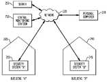
- FIG. 2illustrates an arrangement with two security systems, a personal computer, and a remote facility, according to the invention.
- a first building location (building “A”) 200is secured by a first security system (security system “A”) 205
- a second building location (building “B”) 240is secured by a second security system (security system “B”) 245 .
- the building locationsmay be separate structures, such as individual homes or business facilities. Or, the building locations may be different parts of a common structure, such as different apartments in an apartment building, or the lower and upper levels of a house, for instance. Note that the concept can be extended to more than two security systems and building locations. Moreover, communication between security systems needed not be bi-directional.
- the inventionencompasses a scenario where the first security system 205 can access information regarding the second security system 245 , but the second security system 245 does not have the ability to access information regarding the first security system.
- each security systemhas similar transmit and receive capabilities.
- the security systems 205 and 245each communicate with a remote facility 250 , such as a server, via one or more networks, such as example network 220 .
- the server 250aggregates data from the different security systems 205 , 245 , and communicates with the different security systems.
- the server 250may also report urgent information such as alarms to a central monitoring station 260 .
- the central monitoring station 260is typically a staffed facility where operators monitor incoming communications to determine when an alarm is set by a monitored security system. The operator may attempt to determine if an alarm was set inadvertently by telephoning the secured location. If the alarm was not set inadvertently, the operator contacts emergency services such as fire or police personnel in the appropriate municipality by telephone to report the alarm.
- all communications with the security systems 205 , 245are handled by the server 250 , and the server 250 forwards certain communications such as alarms to the central monitoring station 260 .
- routine communications with the security systems 205 , 245are handled by the server 250 , while alarm message are sent directly to the central monitoring station 260 .
- all communications with the security systems 205 , 245are handled by the central monitoring station 260 , which subsumes the functions of the server 250 .
- the security systems 205 , 245communicate with one or more remote facilities which include computers for storing and processing data, and network interfaces such as receivers and transmitters for receiving and transmitting data, respectively.
- the remote facility 250provides data sharing between the security systems 205 , 245 .
- the network 220can include essentially any type of communication path or paths, including a telephone link, such as a conventional telephone network, to communicate with the remote facility 250 .
- signaling using a compatible modemmay be used.
- the network 220includes a computer network 220 such as the Internet.
- the security systems 205 and 245may use a communications protocol such as TCP/IP to communicate with the remote facility 250 .
- Other communication pathssuch as satellite or RF radio paths, including, e.g., those using GSM or CDMA techniques, may also be used.
- the different security systemsmay use different communication paths, and upstream communications to the remote facility 250 may be on different paths than downstream communication from the remote facility 250 . Multiple paths of the same or different type may also be used for redundancy. The different communication paths may be attempted serially until a successful communication is made.
- the security systems 205 , 245may periodically transmit data to the remote facility 250 at regular update intervals, e.g., every ten seconds.
- This datacan include essentially any information that is maintained by the security system.
- the informationcan include an armed status indicating, e.g., whether the security system is armed and whether zones are bypassed, a trouble code, a maintenance status, or the like.
- the informationcan also indicate whether a door or window is open, and whether a motion sensor has been tripped.
- Video and audio datacan also be provided to the remote facility 250 .
- the security systemmay interact with, or be part of, a home automation network, in which case information regarding the home automation network can be provided. This may include, for instance, heating or air conditioning system settings.
- Information from a medical devicesuch as a heart rate monitor can also be provided to the remote facility 250 , e.g., to allow a user to check in on the medical condition of a relative.
- the remote facility 250processes the message and performs an action according to control logic implemented therein. For example, if the remote facility 250 receives data from security system “A” 205 indicating that an alarm has been tripped, the remote facility can notify security system “B” 245 of this fact by transmitting a signal to it to cause it to provide an appropriate message to a user.
- the messages from the respective security systemsmay include identifiers that identify the security systems.
- the remote facility 250can maintain data regarding the identity of one or more security systems that are to be notified when a specified occurrence is detected at one or more other security systems. This data can be configured beforehand by the operator of the remote facility 250 by obtaining appropriate permissions of the users of the different security systems.
- the remote facility 250can send commands to one or more security systems based on commands received from one or more other security systems. For example, in the above example, where security system “B” 245 is notified that an alarm has been tripped at security system “A” 205 , the user at security system “B” 245 may telephone a person at the location of security system “A” 205 , or a nearby location, such as a neighbor's home, to determine if the alarm was a false alarm. If it was a false alarm, the user at security system “B” 245 can enter a command to turn off the alarm at security system “A” 205 . The command is transmitted to the remote facility 250 , which, in response, transmits a signal to security system “A” 205 to cause it to turn off the alarm.
- the remote facility 250may determine whether information it has received from one security system is urgent enough that it should be provided to another security system automatically, with being requested, or is routine and therefore can be provided on an as-requested basis.
- security system “A” 205enters a command via a user interface to obtain status information regarding security system “B” 245 .
- security system “A” 205transmits the command to the remote facility 250 , e.g., via transmitters at the telephone network interface 124 or computer network interface 126 , for example.
- the remote facility 250receives and processes the command and performs an action according to control logic implemented therein.
- the remote facility 250accesses its memory to determine the most recent status information that has been received from security system “B” 245 and transmits a message back to security system “A” 205 to inform it of this status.
- Security system “A” 205receives the message, e.g., via receivers at the telephone network interface 124 or computer network interface 126 , for example.
- the security systemcan provide the audio and/or video data in response to a request from a user via the remote facility 250 .
- the audio and/or video datacan be provided on the initiative of the security system when certain events occur, such as an alarm event.
- the audio and/or video datacan be provided with the periodic updates if there is sufficient bandwidth. The transmission of compressed still video frames should be achievable.
- the remote facility 250may also have the capability to download software to a security system to change its behavior, including changing the update interval and other pre-programmed behaviors, such as the types of data transmitted during the periodic updates.
- each security systemmay communicate with the network 220 via a firewall, in which case it is more secure to transmit through the firewall, from the security system to the network, and not from the network to the security system.
- the remote facility 250is continuously informed of the status of the different security systems and can therefore respond to status requests from the security system more quickly than if the remote facility 250 had to query the security systems for each status request.
- a personal computer 270 running appropriate software such as a web browsermay be used to display information to a user regarding the one or more security systems 205 , 245 .
- the usermay enter a command via the web browser to cause the personal computer to connect to a designated web site to request information regarding a specific security system.
- the server 250may provide the web site, for example.
- the web siteaccesses the periodically updated information and provides it to the personal computer 270 to enable the web browser to provide an appropriate display.
- the web siteis hosted by another server that communicates with the server 250 to access the periodically updated information at the server 250 .
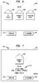
- FIG. 3illustrates a remote facility according to the invention.
- the remote facility 250can include a general purpose computer that is programmed to achieve the functionality described herein.
- the remote facility 250is typically provided at a staffed facility that is remote from the security systems which it serves.
- the staff at the remote facility 250may monitor the alarm status of the different security systems and take appropriate actions such as notifying emergency personnel when an alarm is tripped.
- Multiple remote facilitiesmay be provided as needed to serve multiple security systems.
- the remote facility 250includes an interface 256 , including a receiver and transmitter, for communicating with different security systems via one or more networks.
- a control 254is used to execute software instructions stored in the memory 252 to achieve the desired functionality, including recovering the periodically updated information and other data from the security systems, and initiating transmissions to the security systems.
- a memory resource used for storing software or other instructions that are executed by the control 254 to achieve the functionality described hereinmay be considered a program storage device.
- the memory 252may also store data, e.g., for identifying which security systems are to be notified when an alarm or other specified event occurs at a given security system. Information for contacting each of the security systems may also be stored.
- the remote facility 250 and a security systemmay store an IP address of the security system.
- the interface 256may be a network interface card.
- the remote facility 250 and a security systemcommunicate via a telephone network
- the remote facilitymay store a phone number of the security system as well as modem settings.
- the interface 256may be a modem.
- the remote facility 250may have a number of computers with different interfaces to enable communication with a large number of security systems at the same time via different communication paths. Encryption and authentication protocols may be implemented as well.
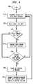
- FIG. 4illustrates a method used by a security system according to the invention.
- the processbegins at block 400 .
- the security systemtransmits status data to the remote facility. It is also possible for the security system to transmit any other data that it has, such as video or audio data.
- a wait period or update intervalis implemented. For example, a ten second wait may be used. It is desirable to have a relatively short update interval so that the remote facility can receive important information from a security system quickly.
- the security systemtransmits the user command to the remote facility. For example, the command may be to obtain status or other information from another security system, or to control another security system, such as by arming or disarming it.
- processingproceeds at block 450 .
- the security systemcarries out the command in the message.
- the messagemay include a command to implement an intercom feature or to provide audio and/or video data. If no message has been received at block 450 , processing proceeds at block 410 .
- the security systemmay transmit a confirmation that the message was received from the remote facility. Other data, such as requested status, video and audio data may be transmitted as well.
- FIG. 5illustrates a method used by a remote facility according to the invention.
- the processbegins at block 500 .
- the remote facilityreceives status data and/or commands from different security systems.
- the remote facilitytransmits a message to one or more other specified security systems, such as a security system “B” (block 530 ). Note that an alarm can be reported to the remote facility with the status data during the periodic transmissions or reported immediately as a separate transmission. If no alarm is reported at block 520 , processing proceeds at block 540 .
- a commandhas been received from a security system, for example, from security system “A”
- the remote facilitytransmits a message with the command to one or more other specified security systems, such as security system “B” (block 550 ). If no command is received at block 540 , processing proceeds at block 560 .
- an intercom requestis received from a security system, for example, from security system “A”
- the remote facilityestablishes two-way communication between security systems “A” and “B” and, optionally, other security systems.
- the Voice over Internet ProtocolVOIP
- the remote facilitycan activate a switch to connect the lines of the security systems.
- the intercom featureallows users at the different security systems to quickly communicate with one another by voice.
- One of the userscan initiate the connection, e.g., by pressing an appropriate key on a user interface.
- the control at the security systemhandles the request and initiates contact with the remote facility via a transmitter.
- a microphone at the security system being contactedcan be made live automatically or in response to a user answering the intercom request.
- FIG. 6illustrates an example user interface that allows a user to select a location, according to the invention.
- the user interface device 140includes a graphical user interface such as a touch screen display 600 for displaying information and receiving user commands or entries. Alternatively, a push button keypad may be used.
- a a speaker 630 and microphone 640may be provided for speech recognition in a voice-activated system, or for use in an intercom. The speaker 630 may also play audio data from another security system.
- the display area 600includes user-friendly identifiers such as icons that identify the local security system and one or more other security systems that can be accessed.
- icons 605 , 610 , and 615represent the security systems associated with the user's house (in which the interface 140 is located), the parent's house, and the vacation house, respectively.
- the display 600prompts the user to select a location by touching one of the icons. Assuming the user desires to view information regarding the security system at the parent's house, the user touches the icon 610 , which causes the display 700 of FIG. 7 to appear.
- the browsermay provide a graphical user interface and display similar to that discussed and shown for the user interface device 140 to display information to the user and receive commands from the user. Commands may be received via an appropriate input device such as a mouse, for instance.
- FIG. 7illustrates an example user interface displaying information regarding a selected location, according to the invention.
- the security system associated with the user interface device 140transmits a request to the remote facility to obtain the information regarding the security system at the parent's house.
- the remote facilityreplies by transmitting the periodically updated information that it has maintained to the local security system for use in generating the display 700 .
- the display 700includes a region 710 that indicates that the security system at the parent's house is armed, and that zone 1 , which covers the garage, is bypassed.
- the usercan control the user interface 140 to view information regarding another remote security system, or regarding the local security system. For example, the user may touch “return” on the display 700 to return to the display 600 of FIG. 6 , then select one of the other house icons to view the corresponding status information.
- the usercan enter a command to change the status of the remote security system, such as by changing the armed status, which zones are bypassed, and so forth.
- the usertouches the area of the screen 700 which displays “change status?”, which causes the display 800 of FIG. 8 to appear.
- FIG. 8illustrates an example user interface that allows a user to change a status, according to the invention.
- the display 800includes a region 810 that allows the user to change the status of the security system at the parent's house, such as by arming or disarming the system. To do this, the user touches the display 800 near the words “arm” or “disarm”. Assuming, the user wishes to disarm the system, the user touches “disarm”, which causes the display 900 of FIG. 9 to appear.
- FIG. 9illustrates an example user interface that allows a user to enter a pass code, according to the invention.
- the display 900includes a region 910 that allows the user to enter a pass code for disarming the security system at the parent's house.
- the region 910provides a keypad which the user activates by touching a sequence of numbers and/or letters, then touching the “#” key, for example, when finished. If the pass code is correct, the user interface 140 initiates a communication from the local security system to the remote facility, which in turn initiates a communication to the security system at the parent's house to disarm the system.
- control logic associated with the user interface device 140allows it to control both the local security system and one or more remote security systems.
- the user interface device 140may include a microprocessor that executes software, firmware, micro-code or the like stored in memory, or a dedicated chip such as an ASIC, to control the local and remote security systems.
- the intelligencecan be carried out at different locations in the security system 100 , such as at the control panel 110 .
- the user interface device 140may be configured by the user or installer with the contact information of the remote facility with which it will communicate.
- the configuration informationmay include, e.g., an IP address, telephone number, or serial number, password or other identifier of the remote facility.
- Menu promptsmay be displayed on the user interface device 140 to allow the user or installer to identify and configure the information.
- the user interface device 140may also be configured with access information for changing the status of the other security systems, such as the pass codes for arming and disarming the other systems.
Landscapes
- Business, Economics & Management (AREA)
- Emergency Management (AREA)
- Physics & Mathematics (AREA)
- General Physics & Mathematics (AREA)
- Alarm Systems (AREA)
- Interconnected Communication Systems, Intercoms, And Interphones (AREA)
Abstract
Description
Claims (19)
Priority Applications (1)
| Application Number | Priority Date | Filing Date | Title |
|---|---|---|---|
| US11/858,252US7633388B2 (en) | 2004-10-20 | 2007-09-20 | Method and apparatus for interfacing security systems by periodic check in with remote facility |
Applications Claiming Priority (2)
| Application Number | Priority Date | Filing Date | Title |
|---|---|---|---|
| US10/969,099US7292142B2 (en) | 2004-10-20 | 2004-10-20 | Method and apparatus for interfacing security systems by periodic check in with remote facility |
| US11/858,252US7633388B2 (en) | 2004-10-20 | 2007-09-20 | Method and apparatus for interfacing security systems by periodic check in with remote facility |
Related Parent Applications (1)
| Application Number | Title | Priority Date | Filing Date |
|---|---|---|---|
| US10/969,099ContinuationUS7292142B2 (en) | 2004-10-20 | 2004-10-20 | Method and apparatus for interfacing security systems by periodic check in with remote facility |
Publications (2)
| Publication Number | Publication Date |
|---|---|
| US20080061923A1 US20080061923A1 (en) | 2008-03-13 |
| US7633388B2true US7633388B2 (en) | 2009-12-15 |
Family
ID=35311770
Family Applications (2)
| Application Number | Title | Priority Date | Filing Date |
|---|---|---|---|
| US10/969,099Expired - LifetimeUS7292142B2 (en) | 2004-10-20 | 2004-10-20 | Method and apparatus for interfacing security systems by periodic check in with remote facility |
| US11/858,252Expired - LifetimeUS7633388B2 (en) | 2004-10-20 | 2007-09-20 | Method and apparatus for interfacing security systems by periodic check in with remote facility |
Family Applications Before (1)
| Application Number | Title | Priority Date | Filing Date |
|---|---|---|---|
| US10/969,099Expired - LifetimeUS7292142B2 (en) | 2004-10-20 | 2004-10-20 | Method and apparatus for interfacing security systems by periodic check in with remote facility |
Country Status (7)
| Country | Link |
|---|---|
| US (2) | US7292142B2 (en) |
| EP (3) | EP2221788B1 (en) |
| AT (1) | ATE502367T1 (en) |
| AU (1) | AU2005220228A1 (en) |
| CA (1) | CA2523728C (en) |
| DE (1) | DE602005027011D1 (en) |
| ES (1) | ES2361657T3 (en) |
Cited By (10)
| Publication number | Priority date | Publication date | Assignee | Title |
|---|---|---|---|---|
| US7825796B1 (en)* | 2008-04-04 | 2010-11-02 | Daniel Michael Simon | Remote security panel access system for enabling access to a plurality of remote security panels and methods of enabling remote panel access |
| US20120206259A1 (en)* | 2011-02-15 | 2012-08-16 | Earnest Gassaway | System and method for remote alarm management of one or more objects |
| US8665084B2 (en) | 2011-07-29 | 2014-03-04 | Adt Us Holdings, Inc. | Security system and method |
| US8786425B1 (en)* | 2011-09-09 | 2014-07-22 | Alarm.Com Incorporated | Aberration engine |
| AU2011203344B2 (en)* | 2011-07-07 | 2014-09-25 | Gallagher Group Limited | A Security System |
| US10846387B2 (en) | 2017-07-12 | 2020-11-24 | At&T Intellectual Property I, L.P. | Managing access based on activities of entities |
| US11158174B2 (en) | 2019-07-12 | 2021-10-26 | Carrier Corporation | Security system with distributed audio and video sources |
| US11438390B2 (en)* | 2016-12-30 | 2022-09-06 | Motorola Mobility Llc | Automatic call forwarding during system updates |
| US12159526B2 (en) | 2015-09-30 | 2024-12-03 | Alarm.Com Incorporated | Abberation detection technology |
| US12307880B2 (en) | 2022-08-29 | 2025-05-20 | Comcast Cable Communications, Llc | Systems and methods for determining status of sensors |
Families Citing this family (135)
| Publication number | Priority date | Publication date | Assignee | Title |
|---|---|---|---|---|
| US8089353B2 (en)* | 2006-08-05 | 2012-01-03 | Min Ming Tarng | 4Less—Xtaless, capless, indless, dioless TSOC design of SOC or 4Free—Xtalfree, capfree, indfree, diofree TSOC design of SOC |
| US6658091B1 (en) | 2002-02-01 | 2003-12-02 | @Security Broadband Corp. | LIfestyle multimedia security system |
| US7793003B2 (en)* | 2003-01-31 | 2010-09-07 | Qwest Communications International Inc | Systems and methods for integrating microservers with a network interface device |
| US7679221B2 (en)* | 2004-02-02 | 2010-03-16 | Botem Electronic Co., Ltd. | Power saving switch |
| US10348575B2 (en) | 2013-06-27 | 2019-07-09 | Icontrol Networks, Inc. | Control system user interface |
| US10382452B1 (en) | 2007-06-12 | 2019-08-13 | Icontrol Networks, Inc. | Communication protocols in integrated systems |
| US10142392B2 (en) | 2007-01-24 | 2018-11-27 | Icontrol Networks, Inc. | Methods and systems for improved system performance |
| US11190578B2 (en) | 2008-08-11 | 2021-11-30 | Icontrol Networks, Inc. | Integrated cloud system with lightweight gateway for premises automation |
| US12063220B2 (en) | 2004-03-16 | 2024-08-13 | Icontrol Networks, Inc. | Communication protocols in integrated systems |
| US10237237B2 (en) | 2007-06-12 | 2019-03-19 | Icontrol Networks, Inc. | Communication protocols in integrated systems |
| US10156959B2 (en) | 2005-03-16 | 2018-12-18 | Icontrol Networks, Inc. | Cross-client sensor user interface in an integrated security network |
| US11489812B2 (en) | 2004-03-16 | 2022-11-01 | Icontrol Networks, Inc. | Forming a security network including integrated security system components and network devices |
| US10313303B2 (en) | 2007-06-12 | 2019-06-04 | Icontrol Networks, Inc. | Forming a security network including integrated security system components and network devices |
| GB2428821B (en) | 2004-03-16 | 2008-06-04 | Icontrol Networks Inc | Premises management system |
| US8963713B2 (en) | 2005-03-16 | 2015-02-24 | Icontrol Networks, Inc. | Integrated security network with security alarm signaling system |
| US11677577B2 (en) | 2004-03-16 | 2023-06-13 | Icontrol Networks, Inc. | Premises system management using status signal |
| US9609003B1 (en) | 2007-06-12 | 2017-03-28 | Icontrol Networks, Inc. | Generating risk profile using data of home monitoring and security system |
| US10444964B2 (en) | 2007-06-12 | 2019-10-15 | Icontrol Networks, Inc. | Control system user interface |
| US9531593B2 (en) | 2007-06-12 | 2016-12-27 | Icontrol Networks, Inc. | Takeover processes in security network integrated with premise security system |
| US11244545B2 (en) | 2004-03-16 | 2022-02-08 | Icontrol Networks, Inc. | Cross-client sensor user interface in an integrated security network |
| US20090077623A1 (en) | 2005-03-16 | 2009-03-19 | Marc Baum | Security Network Integrating Security System and Network Devices |
| US8635350B2 (en) | 2006-06-12 | 2014-01-21 | Icontrol Networks, Inc. | IP device discovery systems and methods |
| US7711796B2 (en) | 2006-06-12 | 2010-05-04 | Icontrol Networks, Inc. | Gateway registry methods and systems |
| US11277465B2 (en) | 2004-03-16 | 2022-03-15 | Icontrol Networks, Inc. | Generating risk profile using data of home monitoring and security system |
| US11201755B2 (en) | 2004-03-16 | 2021-12-14 | Icontrol Networks, Inc. | Premises system management using status signal |
| US11316958B2 (en) | 2008-08-11 | 2022-04-26 | Icontrol Networks, Inc. | Virtual device systems and methods |
| US11343380B2 (en) | 2004-03-16 | 2022-05-24 | Icontrol Networks, Inc. | Premises system automation |
| US10522026B2 (en) | 2008-08-11 | 2019-12-31 | Icontrol Networks, Inc. | Automation system user interface with three-dimensional display |
| US11582065B2 (en) | 2007-06-12 | 2023-02-14 | Icontrol Networks, Inc. | Systems and methods for device communication |
| US10721087B2 (en) | 2005-03-16 | 2020-07-21 | Icontrol Networks, Inc. | Method for networked touchscreen with integrated interfaces |
| US8988221B2 (en) | 2005-03-16 | 2015-03-24 | Icontrol Networks, Inc. | Integrated security system with parallel processing architecture |
| US11916870B2 (en) | 2004-03-16 | 2024-02-27 | Icontrol Networks, Inc. | Gateway registry methods and systems |
| US11113950B2 (en) | 2005-03-16 | 2021-09-07 | Icontrol Networks, Inc. | Gateway integrated with premises security system |
| US10200504B2 (en) | 2007-06-12 | 2019-02-05 | Icontrol Networks, Inc. | Communication protocols over internet protocol (IP) networks |
| US10339791B2 (en) | 2007-06-12 | 2019-07-02 | Icontrol Networks, Inc. | Security network integrated with premise security system |
| US20170118037A1 (en) | 2008-08-11 | 2017-04-27 | Icontrol Networks, Inc. | Integrated cloud system for premises automation |
| US9191228B2 (en) | 2005-03-16 | 2015-11-17 | Icontrol Networks, Inc. | Cross-client sensor user interface in an integrated security network |
| US11159484B2 (en) | 2004-03-16 | 2021-10-26 | Icontrol Networks, Inc. | Forming a security network including integrated security system components and network devices |
| US11368429B2 (en) | 2004-03-16 | 2022-06-21 | Icontrol Networks, Inc. | Premises management configuration and control |
| US9141276B2 (en) | 2005-03-16 | 2015-09-22 | Icontrol Networks, Inc. | Integrated interface for mobile device |
| US11811845B2 (en) | 2004-03-16 | 2023-11-07 | Icontrol Networks, Inc. | Communication protocols over internet protocol (IP) networks |
| US10375253B2 (en) | 2008-08-25 | 2019-08-06 | Icontrol Networks, Inc. | Security system with networked touchscreen and gateway |
| US9729342B2 (en) | 2010-12-20 | 2017-08-08 | Icontrol Networks, Inc. | Defining and implementing sensor triggered response rules |
| US11496568B2 (en) | 2005-03-16 | 2022-11-08 | Icontrol Networks, Inc. | Security system with networked touchscreen |
| US20120324566A1 (en) | 2005-03-16 | 2012-12-20 | Marc Baum | Takeover Processes In Security Network Integrated With Premise Security System |
| US20170180198A1 (en) | 2008-08-11 | 2017-06-22 | Marc Baum | Forming a security network including integrated security system components |
| US10999254B2 (en) | 2005-03-16 | 2021-05-04 | Icontrol Networks, Inc. | System for data routing in networks |
| US20110128378A1 (en) | 2005-03-16 | 2011-06-02 | Reza Raji | Modular Electronic Display Platform |
| US9306809B2 (en) | 2007-06-12 | 2016-04-05 | Icontrol Networks, Inc. | Security system with networked touchscreen |
| US11615697B2 (en) | 2005-03-16 | 2023-03-28 | Icontrol Networks, Inc. | Premise management systems and methods |
| US11700142B2 (en) | 2005-03-16 | 2023-07-11 | Icontrol Networks, Inc. | Security network integrating security system and network devices |
| US7353034B2 (en) | 2005-04-04 | 2008-04-01 | X One, Inc. | Location sharing and tracking using mobile phones or other wireless devices |
| JP4505740B2 (en) | 2005-05-16 | 2010-07-21 | ソニー株式会社 | Imaging apparatus and method for starting the same |
| US7965178B1 (en)* | 2005-09-26 | 2011-06-21 | Schmutter Bruce E | System and method for integrated facility and fireground management |
| GB0524044D0 (en)* | 2005-11-25 | 2006-01-04 | Intamac Systems Ltd | Security system and services |
| US7515042B2 (en)* | 2006-05-25 | 2009-04-07 | Alcatel-Lucent Usa Inc. | Mobile surveillance |
| US10079839B1 (en) | 2007-06-12 | 2018-09-18 | Icontrol Networks, Inc. | Activation of gateway device |
| US12063221B2 (en) | 2006-06-12 | 2024-08-13 | Icontrol Networks, Inc. | Activation of gateway device |
| US11706279B2 (en) | 2007-01-24 | 2023-07-18 | Icontrol Networks, Inc. | Methods and systems for data communication |
| US7633385B2 (en) | 2007-02-28 | 2009-12-15 | Ucontrol, Inc. | Method and system for communicating with and controlling an alarm system from a remote server |
| US8451986B2 (en) | 2007-04-23 | 2013-05-28 | Icontrol Networks, Inc. | Method and system for automatically providing alternate network access for telecommunications |
| US10523689B2 (en) | 2007-06-12 | 2019-12-31 | Icontrol Networks, Inc. | Communication protocols over internet protocol (IP) networks |
| US11089122B2 (en) | 2007-06-12 | 2021-08-10 | Icontrol Networks, Inc. | Controlling data routing among networks |
| US11601810B2 (en) | 2007-06-12 | 2023-03-07 | Icontrol Networks, Inc. | Communication protocols in integrated systems |
| US10498830B2 (en) | 2007-06-12 | 2019-12-03 | Icontrol Networks, Inc. | Wi-Fi-to-serial encapsulation in systems |
| US11646907B2 (en) | 2007-06-12 | 2023-05-09 | Icontrol Networks, Inc. | Communication protocols in integrated systems |
| US11316753B2 (en) | 2007-06-12 | 2022-04-26 | Icontrol Networks, Inc. | Communication protocols in integrated systems |
| US10666523B2 (en) | 2007-06-12 | 2020-05-26 | Icontrol Networks, Inc. | Communication protocols in integrated systems |
| US11237714B2 (en) | 2007-06-12 | 2022-02-01 | Control Networks, Inc. | Control system user interface |
| US12184443B2 (en) | 2007-06-12 | 2024-12-31 | Icontrol Networks, Inc. | Controlling data routing among networks |
| US20180198788A1 (en)* | 2007-06-12 | 2018-07-12 | Icontrol Networks, Inc. | Security system integrated with social media platform |
| US10389736B2 (en) | 2007-06-12 | 2019-08-20 | Icontrol Networks, Inc. | Communication protocols in integrated systems |
| US10423309B2 (en) | 2007-06-12 | 2019-09-24 | Icontrol Networks, Inc. | Device integration framework |
| US11218878B2 (en) | 2007-06-12 | 2022-01-04 | Icontrol Networks, Inc. | Communication protocols in integrated systems |
| US12283172B2 (en) | 2007-06-12 | 2025-04-22 | Icontrol Networks, Inc. | Communication protocols in integrated systems |
| US12003387B2 (en) | 2012-06-27 | 2024-06-04 | Comcast Cable Communications, Llc | Control system user interface |
| US10616075B2 (en) | 2007-06-12 | 2020-04-07 | Icontrol Networks, Inc. | Communication protocols in integrated systems |
| US10051078B2 (en) | 2007-06-12 | 2018-08-14 | Icontrol Networks, Inc. | WiFi-to-serial encapsulation in systems |
| US11212192B2 (en) | 2007-06-12 | 2021-12-28 | Icontrol Networks, Inc. | Communication protocols in integrated systems |
| US11423756B2 (en) | 2007-06-12 | 2022-08-23 | Icontrol Networks, Inc. | Communication protocols in integrated systems |
| US20090031381A1 (en)* | 2007-07-24 | 2009-01-29 | Honeywell International, Inc. | Proxy video server for video surveillance |
| US10223903B2 (en) | 2010-09-28 | 2019-03-05 | Icontrol Networks, Inc. | Integrated security system with parallel processing architecture |
| US11831462B2 (en) | 2007-08-24 | 2023-11-28 | Icontrol Networks, Inc. | Controlling data routing in premises management systems |
| US10120105B2 (en) | 2007-10-23 | 2018-11-06 | La Crosse Technology Ltd. | Location monitoring via a gateway |
| US8154398B2 (en) | 2007-10-23 | 2012-04-10 | La Crosse Technology | Remote location monitoring |
| US10237358B2 (en) | 2007-10-23 | 2019-03-19 | La Crosse Technology Ltd. | Location monitoring via a gateway |
| US10599303B2 (en) | 2007-10-23 | 2020-03-24 | La Crosse Technology Ltd. | Remote location monitoring |
| US9528861B1 (en) | 2007-10-23 | 2016-12-27 | La Crosse Technology | Remote location monitoring |
| US8412922B2 (en)* | 2007-10-24 | 2013-04-02 | Sercomm Corporation | On-site configuration of a hardware device module of a security system |
| US9154379B2 (en)* | 2007-10-25 | 2015-10-06 | Sercomm Corporation | Remote configuration of a hardware device module of a security system |
| JP2009164738A (en) | 2007-12-28 | 2009-07-23 | Omron Corp | Remote monitoring system, remote monitoring terminal, and remote monitoring terminal control program |
| US11916928B2 (en) | 2008-01-24 | 2024-02-27 | Icontrol Networks, Inc. | Communication protocols over internet protocol (IP) networks |
| US20090232307A1 (en)* | 2008-03-11 | 2009-09-17 | Honeywell International, Inc. | Method of establishing virtual security keypad session from a mobile device using java virtual machine |
| US8526909B2 (en)* | 2008-03-27 | 2013-09-03 | At&T Mobility Ii Llc | Systems and methods for activating a security system upon receipt of emergency alert messages |
| US20090289787A1 (en)* | 2008-05-21 | 2009-11-26 | International Business Machines Corporation | Residential security cluster with associated alarm interconnects |
| US20170185278A1 (en) | 2008-08-11 | 2017-06-29 | Icontrol Networks, Inc. | Automation system user interface |
| US11729255B2 (en) | 2008-08-11 | 2023-08-15 | Icontrol Networks, Inc. | Integrated cloud system with lightweight gateway for premises automation |
| US11258625B2 (en) | 2008-08-11 | 2022-02-22 | Icontrol Networks, Inc. | Mobile premises automation platform |
| US11758026B2 (en) | 2008-08-11 | 2023-09-12 | Icontrol Networks, Inc. | Virtual device systems and methods |
| US11792036B2 (en) | 2008-08-11 | 2023-10-17 | Icontrol Networks, Inc. | Mobile premises automation platform |
| US8638211B2 (en) | 2009-04-30 | 2014-01-28 | Icontrol Networks, Inc. | Configurable controller and interface for home SMA, phone and multimedia |
| US8405499B2 (en) | 2009-08-07 | 2013-03-26 | At&T Intellectual Property I, L.P. | Methods, systems, and products for security services |
| US8937658B2 (en) | 2009-10-15 | 2015-01-20 | At&T Intellectual Property I, L.P. | Methods, systems, and products for security services |
| DE102009060418A1 (en)* | 2009-12-22 | 2011-06-30 | Minimax GmbH & Co. KG, 23843 | Test device for hazard alarm systems |
| KR101072593B1 (en)* | 2010-03-02 | 2011-10-11 | 안현진 | Unmanned guard system using network |
| US8456278B1 (en) | 2010-03-24 | 2013-06-04 | Resolution Products, Inc. | Communicating within a wireless security system |
| WO2011143273A1 (en) | 2010-05-10 | 2011-11-17 | Icontrol Networks, Inc | Control system user interface |
| US8836467B1 (en) | 2010-09-28 | 2014-09-16 | Icontrol Networks, Inc. | Method, system and apparatus for automated reporting of account and sensor zone information to a central station |
| US11750414B2 (en) | 2010-12-16 | 2023-09-05 | Icontrol Networks, Inc. | Bidirectional security sensor communication for a premises security system |
| US9147337B2 (en) | 2010-12-17 | 2015-09-29 | Icontrol Networks, Inc. | Method and system for logging security event data |
| TW201228339A (en)* | 2010-12-28 | 2012-07-01 | Hon Hai Prec Ind Co Ltd | Remote entrance guard reply system and method |
| US20120257615A1 (en) | 2011-04-05 | 2012-10-11 | Honeywell International Inc. | Self-Contained Security System Including Voice and Video Calls Via the Internet |
| US20130014058A1 (en)* | 2011-07-07 | 2013-01-10 | Gallagher Group Limited | Security System |
| US8692665B2 (en) | 2011-11-10 | 2014-04-08 | At&T Intellectual Property I, L.P. | Methods, systems, and products for security services |
| US8902740B2 (en) | 2011-11-10 | 2014-12-02 | At&T Intellectual Property I, L.P. | Methods, systems, and products for security services |
| US9379915B2 (en) | 2011-11-10 | 2016-06-28 | At&T Intellectual Property I, L.P. | Methods, systems, and products for security services |
| US9277381B2 (en) | 2011-11-10 | 2016-03-01 | At&T Intellectual Property I, L.P. | Methods, systems, and products for security services |
| US9396634B2 (en) | 2011-11-10 | 2016-07-19 | At&T Intellectual Property I, L.P. | Methods, systems, and products for security services |
| US9767676B2 (en)* | 2012-01-11 | 2017-09-19 | Honeywell International Inc. | Security system storage of persistent data |
| US9041527B2 (en)* | 2012-04-20 | 2015-05-26 | Numerex Corp. | System and method for using alarm system zones for remote objects |
| JP6260101B2 (en)* | 2012-05-01 | 2018-01-17 | 株式会社リコー | Communication terminal, starting method and program |
| US9419735B2 (en) | 2012-09-07 | 2016-08-16 | Comcast Cable Communcations, LLC | Data usage monitoring |
| US9589453B2 (en) | 2013-03-14 | 2017-03-07 | Vivint, Inc. | Dynamic linking of security systems |
| US11146637B2 (en) | 2014-03-03 | 2021-10-12 | Icontrol Networks, Inc. | Media content management |
| US11405463B2 (en) | 2014-03-03 | 2022-08-02 | Icontrol Networks, Inc. | Media content management |
| WO2016061407A1 (en)* | 2014-10-15 | 2016-04-21 | Avigilon Corporation | Distributed security system over multiple sites |
| US10373453B2 (en) | 2015-09-15 | 2019-08-06 | At&T Intellectual Property I, L.P. | Methods, systems, and products for security services |
| US10565840B2 (en) | 2015-11-12 | 2020-02-18 | At&T Intellectual Property I, L.P. | Alarm reporting |
| CN109479050A (en) | 2016-03-29 | 2019-03-15 | 分辨率产品公司 | Universal Protocol Converter |
| CN106297163A (en)* | 2016-08-17 | 2017-01-04 | 成都环球物讯科技有限责任公司 | A kind of community intelligent safety management system |
| CN106297167A (en)* | 2016-08-28 | 2017-01-04 | 姜俊 | A kind of intelligent domestic system |
| JP6405428B2 (en)* | 2017-08-23 | 2018-10-17 | 綜合警備保障株式会社 | Security control device and security method |
| JP6389936B2 (en)* | 2017-08-23 | 2018-09-12 | 綜合警備保障株式会社 | Security center apparatus and security method |
| TWI792453B (en)* | 2021-07-27 | 2023-02-11 | 中興保全科技股份有限公司 | Security intercom |
| CN115185621B (en)* | 2022-07-13 | 2023-05-23 | 广州大彩光电科技有限公司 | Scene arrangement method and device, electronic equipment and storage medium |
Citations (13)
| Publication number | Priority date | Publication date | Assignee | Title |
|---|---|---|---|---|
| EP0039203A2 (en) | 1980-04-26 | 1981-11-04 | The City of Edinburgh District Council | Sheltered housing schemes communications system |
| US4792946A (en) | 1987-04-07 | 1988-12-20 | Spectrum Electronics, Inc. | Wireless local area network for use in neighborhoods |
| US4978946A (en)* | 1987-08-13 | 1990-12-18 | Talkie Tooter (Canada) Ltd. | Personal security communication system |
| US5486812A (en)* | 1990-03-03 | 1996-01-23 | Cedardell Limited | Security arrangement |
| US6078649A (en)* | 1998-12-30 | 2000-06-20 | Bell Atlantic Network Services, Inc. | Remote subscriber loop terminal alarm monitoring |
| DE19913573A1 (en) | 1999-03-25 | 2000-09-28 | Tempa Communication Inc | Home security connection system for controlling multiple buildings has monitoring circuit and server connected via public telephone network to management system |
| WO2002095702A1 (en) | 2001-05-21 | 2002-11-28 | Intamac Systems Limited | Security system |
| US20030227540A1 (en) | 2002-06-05 | 2003-12-11 | Monroe David A. | Emergency telephone with integrated surveillance system connectivity |
| US6822946B1 (en)* | 2000-08-24 | 2004-11-23 | Motorola, Inc | Wireless bridge for a broadband network |
| US7035270B2 (en)* | 1999-12-30 | 2006-04-25 | General Instrument Corporation | Home networking gateway |
| US7046985B2 (en)* | 2002-04-02 | 2006-05-16 | Talk Emergency, Llc | Security system |
| US7046142B2 (en)* | 2003-03-05 | 2006-05-16 | Paradox Security Systems Ltd. | Security system user interface |
| US7227461B2 (en)* | 2004-01-19 | 2007-06-05 | Lg Electronics, Inc. | Security confirmation system and method thereof |
- 2004
- 2004-10-20USUS10/969,099patent/US7292142B2/ennot_activeExpired - Lifetime
- 2005
- 2005-10-06AUAU2005220228Apatent/AU2005220228A1/ennot_activeAbandoned
- 2005-10-17CACA2523728Apatent/CA2523728C/ennot_activeExpired - Fee Related
- 2005-10-19ESES10164407Tpatent/ES2361657T3/enactiveActive
- 2005-10-19EPEP10164407Apatent/EP2221788B1/enactiveActive
- 2005-10-19EPEP05022824Apatent/EP1650723A1/ennot_activeCeased
- 2005-10-19EPEP08100534Apatent/EP1912189A1/ennot_activeWithdrawn
- 2005-10-19ATAT10164407Tpatent/ATE502367T1/ennot_activeIP Right Cessation
- 2005-10-19DEDE602005027011Tpatent/DE602005027011D1/enactiveActive
- 2007
- 2007-09-20USUS11/858,252patent/US7633388B2/ennot_activeExpired - Lifetime
Patent Citations (13)
| Publication number | Priority date | Publication date | Assignee | Title |
|---|---|---|---|---|
| EP0039203A2 (en) | 1980-04-26 | 1981-11-04 | The City of Edinburgh District Council | Sheltered housing schemes communications system |
| US4792946A (en) | 1987-04-07 | 1988-12-20 | Spectrum Electronics, Inc. | Wireless local area network for use in neighborhoods |
| US4978946A (en)* | 1987-08-13 | 1990-12-18 | Talkie Tooter (Canada) Ltd. | Personal security communication system |
| US5486812A (en)* | 1990-03-03 | 1996-01-23 | Cedardell Limited | Security arrangement |
| US6078649A (en)* | 1998-12-30 | 2000-06-20 | Bell Atlantic Network Services, Inc. | Remote subscriber loop terminal alarm monitoring |
| DE19913573A1 (en) | 1999-03-25 | 2000-09-28 | Tempa Communication Inc | Home security connection system for controlling multiple buildings has monitoring circuit and server connected via public telephone network to management system |
| US7035270B2 (en)* | 1999-12-30 | 2006-04-25 | General Instrument Corporation | Home networking gateway |
| US6822946B1 (en)* | 2000-08-24 | 2004-11-23 | Motorola, Inc | Wireless bridge for a broadband network |
| WO2002095702A1 (en) | 2001-05-21 | 2002-11-28 | Intamac Systems Limited | Security system |
| US7046985B2 (en)* | 2002-04-02 | 2006-05-16 | Talk Emergency, Llc | Security system |
| US20030227540A1 (en) | 2002-06-05 | 2003-12-11 | Monroe David A. | Emergency telephone with integrated surveillance system connectivity |
| US7046142B2 (en)* | 2003-03-05 | 2006-05-16 | Paradox Security Systems Ltd. | Security system user interface |
| US7227461B2 (en)* | 2004-01-19 | 2007-06-05 | Lg Electronics, Inc. | Security confirmation system and method thereof |
Non-Patent Citations (3)
| Title |
|---|
| "Honeywell Home Controller Gateway(TM)"; printed Apr. 8, 2004 from http://www.eadhome.nl/producten/domotica/honeywell-convenience/honeywell-home-controller-gatewa.html. |
| "Remote Control for Your Home's Heating/Cooling System", Honeywell: Comfort, Energy & Health Solutions, Jun. 2001, printed Apr. 8, 2004 from http://content.honeywell.com/yourhome/tan/tam.asp. |
| W7006A Home Controller Gateway User Guide, Jul. 2001, printed Apr. 8, 2004 from: http://content.honeywell.com/yourhome/ac-automated-controllcentralized-intro.htm. |
Cited By (21)
| Publication number | Priority date | Publication date | Assignee | Title |
|---|---|---|---|---|
| US7825796B1 (en)* | 2008-04-04 | 2010-11-02 | Daniel Michael Simon | Remote security panel access system for enabling access to a plurality of remote security panels and methods of enabling remote panel access |
| US20120206259A1 (en)* | 2011-02-15 | 2012-08-16 | Earnest Gassaway | System and method for remote alarm management of one or more objects |
| AU2011203344B2 (en)* | 2011-07-07 | 2014-09-25 | Gallagher Group Limited | A Security System |
| US9286772B2 (en) | 2011-07-29 | 2016-03-15 | Adt Us Holdings, Inc. | Security system and method |
| US8665084B2 (en) | 2011-07-29 | 2014-03-04 | Adt Us Holdings, Inc. | Security system and method |
| US9117349B2 (en) | 2011-07-29 | 2015-08-25 | Adt Us Holdings, Inc. | Security system having segregated operating software |
| US9589441B2 (en) | 2011-07-29 | 2017-03-07 | Adt Us Holdings, Inc. | Security system and method |
| US9922540B1 (en) | 2011-09-09 | 2018-03-20 | Alarm.Com Incorporated | Aberration engine |
| US11170633B1 (en) | 2011-09-09 | 2021-11-09 | Alarm.Com Incorporated | Aberration engine |
| US9165455B1 (en)* | 2011-09-09 | 2015-10-20 | Alarm.Com Incorporated | Aberration engine |
| US8786425B1 (en)* | 2011-09-09 | 2014-07-22 | Alarm.Com Incorporated | Aberration engine |
| US10546485B1 (en) | 2011-09-09 | 2020-01-28 | Alarm.Com Incorporated | Aberration engine |
| US11862005B2 (en) | 2011-09-09 | 2024-01-02 | Alarm.Com Incorporated | Aberration engine |
| US9489826B1 (en) | 2011-09-09 | 2016-11-08 | Alarm.Com Incorporated | Aberration engine |
| US12159526B2 (en) | 2015-09-30 | 2024-12-03 | Alarm.Com Incorporated | Abberation detection technology |
| US11438390B2 (en)* | 2016-12-30 | 2022-09-06 | Motorola Mobility Llc | Automatic call forwarding during system updates |
| US11568034B2 (en) | 2017-07-12 | 2023-01-31 | At&T Intellectual Property I, L.P. | Managing access based on activities of entities |
| US10846387B2 (en) | 2017-07-12 | 2020-11-24 | At&T Intellectual Property I, L.P. | Managing access based on activities of entities |
| US11158174B2 (en) | 2019-07-12 | 2021-10-26 | Carrier Corporation | Security system with distributed audio and video sources |
| US11282352B2 (en) | 2019-07-12 | 2022-03-22 | Carrier Corporation | Security system with distributed audio and video sources |
| US12307880B2 (en) | 2022-08-29 | 2025-05-20 | Comcast Cable Communications, Llc | Systems and methods for determining status of sensors |
Also Published As
| Publication number | Publication date |
|---|---|
| AU2005220228A1 (en) | 2006-05-04 |
| EP2221788A3 (en) | 2010-09-08 |
| EP1912189A1 (en) | 2008-04-16 |
| CA2523728C (en) | 2014-12-09 |
| CA2523728A1 (en) | 2006-04-20 |
| EP2221788A2 (en) | 2010-08-25 |
| EP2221788B1 (en) | 2011-03-16 |
| US20060092010A1 (en) | 2006-05-04 |
| ATE502367T1 (en) | 2011-04-15 |
| DE602005027011D1 (en) | 2011-04-28 |
| US20080061923A1 (en) | 2008-03-13 |
| US7292142B2 (en) | 2007-11-06 |
| ES2361657T3 (en) | 2011-06-21 |
| EP1650723A1 (en) | 2006-04-26 |
Similar Documents
| Publication | Publication Date | Title |
|---|---|---|
| US7633388B2 (en) | Method and apparatus for interfacing security systems by periodic check in with remote facility | |
| US7248161B2 (en) | Method and apparatus for interfacing security systems | |
| US11373514B2 (en) | Network device management technology | |
| EP1650972B1 (en) | Central station real time monitoring of status and control | |
| US10217335B2 (en) | Dynamic linking of security systems | |
| US7123142B2 (en) | Integrated intercom and security system | |
| KR100937547B1 (en) | Surveillance system | |
| US8378808B1 (en) | Dual intercom-interfaced smoke/fire detection system and associated method | |
| US20060023847A1 (en) | Remote control of a speaker phone device as a standalone device or as part of a security system | |
| US20060012472A1 (en) | Method for remotely changing the sensitivity of a wireless sensor | |
| JP2005352956A (en) | Security system, abnormality report terminal, abnormality report method, and program | |
| JP2009260837A (en) | Home equipment monitoring control system | |
| JP5049029B2 (en) | Remote monitoring system | |
| JP2005208878A (en) | Security system | |
| JP2001309067A (en) | Mobile control and measurement system | |
| RU2303289C1 (en) | System for individual protection of real estate | |
| JP2005141481A (en) | Security system | |
| JP2009278265A (en) | Mobile communication system | |
| JP2006004040A (en) | Security system | |
| JP2001211269A (en) | Supervisory system for specific area | |
| JP2001127897A (en) | Portable telephone home control system | |
| KR20080098943A (en) | Monitoring and remote control system through wireless portable terminal | |
| AU2005323462A1 (en) | Method for remotely changing the sensitivity of a wireless sensor | |
| JP2004029996A (en) | Monitoring system |
Legal Events
| Date | Code | Title | Description |
|---|---|---|---|
| STCF | Information on status: patent grant | Free format text:PATENTED CASE | |
| FPAY | Fee payment | Year of fee payment:4 | |
| FPAY | Fee payment | Year of fee payment:8 | |
| AS | Assignment | Owner name:JPMORGAN CHASE BANK, N.A., AS ADMINISTRATIVE AGENT, NEW YORK Free format text:SECURITY INTEREST;ASSIGNOR:ADEMCO INC.;REEL/FRAME:047337/0577 Effective date:20181025 Owner name:JPMORGAN CHASE BANK, N.A., AS ADMINISTRATIVE AGENT Free format text:SECURITY INTEREST;ASSIGNOR:ADEMCO INC.;REEL/FRAME:047337/0577 Effective date:20181025 | |
| AS | Assignment | Owner name:ADEMCO INC., MINNESOTA Free format text:ASSIGNMENT OF ASSIGNORS INTEREST;ASSIGNOR:HONEYWELL INTERNATIONAL INC.;REEL/FRAME:047909/0425 Effective date:20181029 | |
| AS | Assignment | Owner name:ADEMCO INC., MINNESOTA Free format text:CORRECTIVE ASSIGNMENT TO CORRECT THE PREVIOUS RECORDING BY NULLIFICATION. THE INCORRECTLY RECORDED PATENT NUMBERS 8545483, 8612538 AND 6402691 PREVIOUSLY RECORDED AT REEL: 047909 FRAME: 0425. ASSIGNOR(S) HEREBY CONFIRMS THE ASSIGNMENT;ASSIGNOR:HONEYWELL INTERNATIONAL INC.;REEL/FRAME:050431/0053 Effective date:20190215 | |
| MAFP | Maintenance fee payment | Free format text:PAYMENT OF MAINTENANCE FEE, 12TH YEAR, LARGE ENTITY (ORIGINAL EVENT CODE: M1553); ENTITY STATUS OF PATENT OWNER: LARGE ENTITY Year of fee payment:12 |