US7632590B2 - System and a method for manufacturing an electrolyte using electrodeposition - Google Patents
System and a method for manufacturing an electrolyte using electrodepositionDownload PDFInfo
- Publication number
- US7632590B2 US7632590B2US10/620,675US62067503AUS7632590B2US 7632590 B2US7632590 B2US 7632590B2US 62067503 AUS62067503 AUS 62067503AUS 7632590 B2US7632590 B2US 7632590B2
- Authority
- US
- United States
- Prior art keywords
- polymeric electrolyte
- porous substrate
- substrate
- particles
- electrolyte
- Prior art date
- Legal status (The legal status is an assumption and is not a legal conclusion. Google has not performed a legal analysis and makes no representation as to the accuracy of the status listed.)
- Expired - Fee Related, expires
Links
- 239000003792electrolyteSubstances0.000titleclaimsabstractdescription98
- 238000000034methodMethods0.000titleclaimsabstractdescription53
- 238000004519manufacturing processMethods0.000titleclaimsabstractdescription6
- 238000004070electrodepositionMethods0.000titledescription27
- 239000000758substrateSubstances0.000claimsabstractdescription123
- 230000008878couplingEffects0.000claimsabstractdescription13
- 238000010168coupling processMethods0.000claimsabstractdescription13
- 238000005859coupling reactionMethods0.000claimsabstractdescription13
- 239000002245particleSubstances0.000claimsdescription38
- 150000002500ionsChemical class0.000claimsdescription21
- 238000001652electrophoretic depositionMethods0.000claimsdescription15
- UQSQSQZYBQSBJZ-UHFFFAOYSA-Nfluorosulfonic acidChemical compoundOS(F)(=O)=OUQSQSQZYBQSBJZ-UHFFFAOYSA-N0.000claimsdescription15
- 229920000554ionomerPolymers0.000claimsdescription15
- 238000000151depositionMethods0.000claimsdescription14
- 239000008151electrolyte solutionSubstances0.000claimsdescription14
- 230000008021depositionEffects0.000claimsdescription10
- 230000005684electric fieldEffects0.000claimsdescription10
- 239000011148porous materialSubstances0.000claimsdescription7
- 239000003054catalystSubstances0.000claimsdescription4
- 229910001220stainless steelInorganic materials0.000claimsdescription3
- 239000010935stainless steelSubstances0.000claimsdescription3
- 238000003754machiningMethods0.000claimsdescription2
- 210000002268woolAnatomy0.000claimsdescription2
- 229910000831SteelInorganic materials0.000claims1
- 239000010959steelSubstances0.000claims1
- 239000000446fuelSubstances0.000description49
- 210000004027cellAnatomy0.000description33
- OKKJLVBELUTLKV-UHFFFAOYSA-NMethanolChemical compoundOCOKKJLVBELUTLKV-UHFFFAOYSA-N0.000description21
- 239000012528membraneSubstances0.000description16
- 230000008569processEffects0.000description14
- 230000008961swellingEffects0.000description12
- QVGXLLKOCUKJST-UHFFFAOYSA-Natomic oxygenChemical compound[O]QVGXLLKOCUKJST-UHFFFAOYSA-N0.000description7
- 239000005518polymer electrolyteSubstances0.000description7
- 239000010410layerSubstances0.000description6
- 239000000463materialSubstances0.000description6
- 239000001301oxygenSubstances0.000description5
- 229910052760oxygenInorganic materials0.000description5
- 239000000126substanceSubstances0.000description5
- XLYOFNOQVPJJNP-UHFFFAOYSA-NwaterSubstancesOXLYOFNOQVPJJNP-UHFFFAOYSA-N0.000description5
- 230000015572biosynthetic processEffects0.000description4
- 239000001257hydrogenSubstances0.000description4
- 229910052739hydrogenInorganic materials0.000description4
- 230000009467reductionEffects0.000description4
- 239000007787solidSubstances0.000description4
- UFHFLCQGNIYNRP-UHFFFAOYSA-NHydrogenChemical compound[H][H]UFHFLCQGNIYNRP-UHFFFAOYSA-N0.000description3
- 239000004020conductorSubstances0.000description3
- 230000018044dehydrationEffects0.000description3
- 238000006297dehydration reactionMethods0.000description3
- 230000004048modificationEffects0.000description3
- 238000012986modificationMethods0.000description3
- 238000012546transferMethods0.000description3
- LFQSCWFLJHTTHZ-UHFFFAOYSA-NEthanolChemical compoundCCOLFQSCWFLJHTTHZ-UHFFFAOYSA-N0.000description2
- KFZMGEQAYNKOFK-UHFFFAOYSA-NIsopropanolChemical compoundCC(C)OKFZMGEQAYNKOFK-UHFFFAOYSA-N0.000description2
- NBIIXXVUZAFLBC-UHFFFAOYSA-NPhosphoric acidChemical compoundOP(O)(O)=ONBIIXXVUZAFLBC-UHFFFAOYSA-N0.000description2
- 238000007792additionMethods0.000description2
- 239000000853adhesiveSubstances0.000description2
- 230000001070adhesive effectEffects0.000description2
- 239000007864aqueous solutionSubstances0.000description2
- 239000011248coating agentSubstances0.000description2
- 238000000576coating methodMethods0.000description2
- 238000005137deposition processMethods0.000description2
- 230000005611electricityEffects0.000description2
- 238000006703hydration reactionMethods0.000description2
- 239000007788liquidSubstances0.000description2
- 230000003071parasitic effectEffects0.000description2
- 239000012453solvateSubstances0.000description2
- LSNNMFCWUKXFEE-UHFFFAOYSA-MBisulfiteChemical compoundOS([O-])=OLSNNMFCWUKXFEE-UHFFFAOYSA-M0.000description1
- BVKZGUZCCUSVTD-UHFFFAOYSA-LCarbonateChemical compound[O-]C([O-])=OBVKZGUZCCUSVTD-UHFFFAOYSA-L0.000description1
- 229920003935Flemion®Polymers0.000description1
- 229920000557Nafion®Polymers0.000description1
- 239000012790adhesive layerSubstances0.000description1
- 229910000147aluminium phosphateInorganic materials0.000description1
- 238000013459approachMethods0.000description1
- 230000005540biological transmissionEffects0.000description1
- 238000003421catalytic decomposition reactionMethods0.000description1
- 210000000170cell membraneAnatomy0.000description1
- 238000006243chemical reactionMethods0.000description1
- 230000001627detrimental effectEffects0.000description1
- 238000010586diagramMethods0.000description1
- 238000003487electrochemical reactionMethods0.000description1
- 238000005516engineering processMethods0.000description1
- 238000011049fillingMethods0.000description1
- 239000007789gasSubstances0.000description1
- 230000036571hydrationEffects0.000description1
- 229930195733hydrocarbonNatural products0.000description1
- 150000002430hydrocarbonsChemical class0.000description1
- 150000002431hydrogenChemical class0.000description1
- 238000010348incorporationMethods0.000description1
- 238000009413insulationMethods0.000description1
- 238000005304joiningMethods0.000description1
- 238000012423maintenanceMethods0.000description1
- 229960004838phosphoric acidDrugs0.000description1
- 235000011007phosphoric acidNutrition0.000description1
- 229920000642polymerPolymers0.000description1
- 239000002244precipitateSubstances0.000description1
- 238000001556precipitationMethods0.000description1
- 239000007784solid electrolyteSubstances0.000description1
- 239000000243solutionSubstances0.000description1
- 239000000725suspensionSubstances0.000description1
- 230000035899viabilityEffects0.000description1
Images


Classifications
- C—CHEMISTRY; METALLURGY
- C25—ELECTROLYTIC OR ELECTROPHORETIC PROCESSES; APPARATUS THEREFOR
- C25D—PROCESSES FOR THE ELECTROLYTIC OR ELECTROPHORETIC PRODUCTION OF COATINGS; ELECTROFORMING; APPARATUS THEREFOR
- C25D13/00—Electrophoretic coating characterised by the process
- C25D13/04—Electrophoretic coating characterised by the process with organic material
- C—CHEMISTRY; METALLURGY
- C25—ELECTROLYTIC OR ELECTROPHORETIC PROCESSES; APPARATUS THEREFOR
- C25D—PROCESSES FOR THE ELECTROLYTIC OR ELECTROPHORETIC PRODUCTION OF COATINGS; ELECTROFORMING; APPARATUS THEREFOR
- C25D9/00—Electrolytic coating other than with metals
- C25D9/02—Electrolytic coating other than with metals with organic materials
- H—ELECTRICITY
- H01—ELECTRIC ELEMENTS
- H01M—PROCESSES OR MEANS, e.g. BATTERIES, FOR THE DIRECT CONVERSION OF CHEMICAL ENERGY INTO ELECTRICAL ENERGY
- H01M8/00—Fuel cells; Manufacture thereof
- H01M8/04—Auxiliary arrangements, e.g. for control of pressure or for circulation of fluids
- H01M8/04082—Arrangements for control of reactant parameters, e.g. pressure or concentration
- H01M8/04197—Preventing means for fuel crossover
- H—ELECTRICITY
- H01—ELECTRIC ELEMENTS
- H01M—PROCESSES OR MEANS, e.g. BATTERIES, FOR THE DIRECT CONVERSION OF CHEMICAL ENERGY INTO ELECTRICAL ENERGY
- H01M8/00—Fuel cells; Manufacture thereof
- H01M8/10—Fuel cells with solid electrolytes
- H01M8/1009—Fuel cells with solid electrolytes with one of the reactants being liquid, solid or liquid-charged
- H01M8/1011—Direct alcohol fuel cells [DAFC], e.g. direct methanol fuel cells [DMFC]
- H—ELECTRICITY
- H01—ELECTRIC ELEMENTS
- H01M—PROCESSES OR MEANS, e.g. BATTERIES, FOR THE DIRECT CONVERSION OF CHEMICAL ENERGY INTO ELECTRICAL ENERGY
- H01M8/00—Fuel cells; Manufacture thereof
- H01M8/10—Fuel cells with solid electrolytes
- H01M8/1016—Fuel cells with solid electrolytes characterised by the electrolyte material
- H—ELECTRICITY
- H01—ELECTRIC ELEMENTS
- H01M—PROCESSES OR MEANS, e.g. BATTERIES, FOR THE DIRECT CONVERSION OF CHEMICAL ENERGY INTO ELECTRICAL ENERGY
- H01M2300/00—Electrolytes
- H01M2300/0017—Non-aqueous electrolytes
- H01M2300/0065—Solid electrolytes
- H01M2300/0082—Organic polymers
- H—ELECTRICITY
- H01—ELECTRIC ELEMENTS
- H01M—PROCESSES OR MEANS, e.g. BATTERIES, FOR THE DIRECT CONVERSION OF CHEMICAL ENERGY INTO ELECTRICAL ENERGY
- H01M2300/00—Electrolytes
- H01M2300/0088—Composites
- Y—GENERAL TAGGING OF NEW TECHNOLOGICAL DEVELOPMENTS; GENERAL TAGGING OF CROSS-SECTIONAL TECHNOLOGIES SPANNING OVER SEVERAL SECTIONS OF THE IPC; TECHNICAL SUBJECTS COVERED BY FORMER USPC CROSS-REFERENCE ART COLLECTIONS [XRACs] AND DIGESTS
- Y02—TECHNOLOGIES OR APPLICATIONS FOR MITIGATION OR ADAPTATION AGAINST CLIMATE CHANGE
- Y02E—REDUCTION OF GREENHOUSE GAS [GHG] EMISSIONS, RELATED TO ENERGY GENERATION, TRANSMISSION OR DISTRIBUTION
- Y02E60/00—Enabling technologies; Technologies with a potential or indirect contribution to GHG emissions mitigation
- Y02E60/30—Hydrogen technology
- Y02E60/50—Fuel cells
- Y—GENERAL TAGGING OF NEW TECHNOLOGICAL DEVELOPMENTS; GENERAL TAGGING OF CROSS-SECTIONAL TECHNOLOGIES SPANNING OVER SEVERAL SECTIONS OF THE IPC; TECHNICAL SUBJECTS COVERED BY FORMER USPC CROSS-REFERENCE ART COLLECTIONS [XRACs] AND DIGESTS
- Y02—TECHNOLOGIES OR APPLICATIONS FOR MITIGATION OR ADAPTATION AGAINST CLIMATE CHANGE
- Y02P—CLIMATE CHANGE MITIGATION TECHNOLOGIES IN THE PRODUCTION OR PROCESSING OF GOODS
- Y02P70/00—Climate change mitigation technologies in the production process for final industrial or consumer products
- Y02P70/50—Manufacturing or production processes characterised by the final manufactured product
Definitions
- Fuel cellsconduct an electrochemical reaction between chemicals such as hydrogen and oxygen to produce electricity and heat. Unlike batteries which store useable energy, fuel cells generate useable energy and are more easily “recharged” simply by replenishing the consumed fuel. Moreover, fuel cells are much cleaner and quieter than devices that combust hydrocarbons.
- Fuel cellsprovide a direct current (DC) voltage that may be used to power motors, lights, computers, or any number of electrical appliances. While there are several different types of fuel cells, each using a different chemistry, fuel cells typically have three component parts: an anode, a cathode, and an electrolyte. Fuel cells are usually classified, depending on the type of electrolyte used, into one of five groups: alkaline fuel cells (AFC), phosphoric-acid fuel cells (PAFC), solid oxide fuel cells (SOFC), molten carbonate fuel cells (MCFC), and proton exchange membrane fuel cells (PEMFC). One variant of the PEMFC technology includes direct methanol fuel cells (DMFC), in which liquid methanol is directly fed to the fuel cell as fuel.
- AFCalkaline fuel cells
- PAFCphosphoric-acid fuel cells
- SOFCsolid oxide fuel cells
- MCFCmolten carbonate fuel cells
- PEMFCproton exchange membrane fuel cells
- DMFCdirect methanol fuel cells
- PEMFCstypically function by supplying hydrogen to an anode.
- the hydrogenprovides protons to an electrolyte and releases electrons that pass through an external circuit to reach a cathode located opposite the anode.
- the protonssolvate with water molecules and diffuse through the membrane to the cathode where they react with oxygen that has picked up electrons thereby forming water.
- PEMFCshave a number of distinct advantages over other fuel cells. PEMFCs have a very high power density (40% to 60% efficiency) and a very low operating temperature (around 80 degrees Celsius). Moreover PEMFCs do not utilized dangerous chemicals that may spill or leak. These qualities make PEMFCs extremely safe and low in maintenance requirements.
- the proton exchange membrane (PEM) of a PEMFChas been formed by applying a solid semipermeable membrane to an electrode layer with an adhesive layer between the two. The membrane-adhesion layer electrode stack would then be compressed in the presence of heat to bond the layers together.
- traditional methods of forming PEM fuel cellstend to have a low amount of mechanical stability and are susceptible to swelling of the electrolyte. This swelling of the electrolyte often leads to increased fuel crossover resulting in degraded fuel efficiency of the fuel cell.
- a method for manufacturing an electrolyteincludes coupling a substrate to a charged electrode; and electrodepositing a polymeric electrolyte on the substrate.
- FIG. 1illustrates a cross-sectional view of a proton exchange membrane fuel cell (PEMFC) according to one exemplary embodiment.
- PEMFCproton exchange membrane fuel cell
- FIG. 2is a cross-sectional view illustrating an electrodeposition system according to one exemplary embodiment.
- FIG. 3is flow chart illustrating a method of coating a conductive porous substrate with polymeric electrolyte according to one exemplary embodiment.
- FIG. 4Ais a cross-sectional view illustrating the electrophoretic deposition of a conductive porous substrate according to one exemplary embodiment.
- FIG. 4Bis a cross-sectional view illustrating a post deposition treatment that may be performed on a conductive porous substrate according to one exemplary embodiment.
- FIG. 4Cis a cross-sectional view illustrating the electrolytic deposition of a conductive porous substrate according to one exemplary embodiment.
- FIG. 5is a cross sectional view illustrating an electrodeposition system according to one exemplary embodiment.
- FIG. 6is a flow chart illustrating a method of coating a non-conductive porous substrate with polymeric electrolyte according to one exemplary embodiment.
- FIG. 7Ais a cross-sectional view illustrating the electrophoretic deposition of a non-conductive porous substrate according to one exemplary embodiment.
- FIG. 7Bis a cross-sectional view further illustrating the electrophoretic deposition of a non-conductive porous substrate according to one exemplary embodiment.
- An apparatus and a method for forming an electrolyte that reduces the likelihood of swelling in a fuel cell while increasing structural supportis described herein.
- a method for the electrodeposition of polymeric electrolyte on a porous substrateis presented.
- the present system and method for the electrodeposition of polymeric electrolyte on a porous substratewill be described, for ease of explanation only, in the context of a proton exchange membrane fuel cell (PEMFC) including direct methanol fuel cells (DMFC).
- PEMFCproton exchange membrane fuel cell
- DMFCdirect methanol fuel cells
- the apparatus and method described hereinmay be used to form the electrolyte of any type of fuel cell.
- Electrodepositionis meant to be understood both here and in the appended claims to mean the precipitation of a material at an electrode as the result of a passage of an electric current through or an application of an electrical field on a solution or suspension of material.
- electrolyteis meant to be understood broadly as referring to a substance, either solid or liquid, that will provide ionic conductivity when dissolved in water or when in contact with it.
- One solid electrolyte, used originally in fuel cells,is a polymer of perflourinated sulfonic acid.
- FIG. 1illustrates a cross-sectional view of a proton exchange membrane fuel cell (PEMFC) ( 100 ) according to one exemplary embodiment.
- a PEMFCmay include a housing ( 110 ) that surrounds a membrane/electrode assembly (MEA).
- the MEAmay include an anode ( 140 ) and a cathode ( 160 ) surrounding a proton exchange membrane (PEM) ( 150 ).
- a catalyst ( 170 )is also disposed on the boundary between the anode ( 140 ) and the PEM ( 150 ) as well as between the cathode ( 160 ) and the PEM ( 150 ).
- the anode ( 140 ) and the cathode ( 160 )may also be electrically coupled to an electrical load ( 180 ).
- the housing ( 110 ) of the PEMFC ( 100 ) illustrated in FIG. 1may be configured to form a number of chambers.
- the chambers formed by the housing ( 110 )may provide fuel ( 120 ) to the anode ( 140 ) and oxygen ( 130 ) to the cathode ( 160 ) as illustrated in FIG. 1 .
- the fuel ( 120 )typically hydrogen
- the anode ( 140 )where it undergoes a catalytic decomposition into both protons and electrons.
- the electronsare transferred from the anode ( 140 ) to an external circuit or load ( 180 ) and back to the cathode ( 160 ) of the PEMFC ( 100 ).
- the electrons that have returned to the cathodethen combine with the oxygen ( 130 ) provided at the cathode.
- the protonssolvate with water molecules and pass through the proton exchange membrane ( 150 ) where they are also presented at the cathode ( 160 ).
- the protonsthen join the oxygen, forming water molecules ( 190 ).
- the PEM ( 150 )forms a crucial part of the above-mentioned process.
- the PEM ( 150 )may be made of any material capable of transporting the above-mentioned protons, while providing resistance to gas crossover between the anode ( 140 ) and cathode ( 160 ) side including, but in no way limited to, a solid polymer electrolyte membrane such as perfluorosulfonate ionomer membrane.
- perfluorosulfonate ionomer membraneinclude NAFION, FLEMION, and DOW XUS.
- Fuel crossoveris meant to be understood both here and in the appended claims as a parasitic loss of unreacted or partially reacted fuel across a fuel cell membrane, potentially leading to unwanted parasitic reactions. This loss of fuel effectively reduces the overall efficiency of the PEMFC ( 100 ).
- the unreacted or partially reacted fuel that may be lost due to fuel crossovermay include, but is in no way limited to, methanol (in a DMFC), isopropanol, ethanol, or any other fuel that may be used in a fuel cell suffering from fuel crossover.
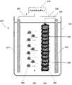
- FIG. 2shows a cross-sectional view of an electrodeposition system configured to deposit polymeric electrolytes on a conductive porous substrate such that swelling and structural instability may be reduced.
- the electrodeposition system ( 200 )may include a power supply ( 210 ) having both a positive lead ( 280 ) and a negative lead ( 220 ).
- the positive lead ( 280 )is electrically connected to a positively charged electrode ( 270 ).
- the negative lead ( 220 )is electrically connected to a negatively charged electrode ( 240 ) which is subsequently electrically coupled to an electrically conductive, porous substrate ( 250 ).
- the electrodeposition system illustrated in FIG. 2also shows a positively charged electrode ( 270 ), a negatively charged electrode ( 240 ), and a porous substrate submersed in a container ( 230 ) filled with a polymeric electrolyte solution ( 260 ).
- the power supply ( 210 ) illustrated in FIG. 2is a direct current (DC) power supply capable of providing voltage to the electrodes ( 270 , 240 ) sufficient to produce an electric field for the electrodeposition of a polymeric electrolyte.
- the positive ( 280 ) and negative ( 220 ) leads that are electrically coupling the electrodes ( 270 , 240 ) to the power supply ( 210 )may be any electrical conductor capable of transmitting a DC signal from a power supply to electrodes including, but in no way limited to, conductive signal wire or conductive straps.
- the electrically conductive, porous substrate ( 250 ) shown in FIG. 2may include a number of pores ( 255 ) configured to receive a polymeric electrolyte and facilitate the transmission of protons.
- the electrically conductive, porous substrate ( 250 ) illustrated in FIG. 2may be made of any conductive substrate capable of both providing mechanical support to a PEM and being sufficiently porous as to not unduly limit the flow of the above-mentioned protons.
- the conductive substratemay include, but is in no way limited to, stainless steel wool, porous stainless steel, etc.
- the present electrodeposition system and methodis in no way limited to porous substrates. The present electrodeposition system and method may also be performed on a dense, non-porous substrate.
- the polymeric electrolyte solution ( 260 ) illustrated in FIG. 2may either contain charged particles ( 400 ; FIG. 4A ) or charged ions ( 420 ; FIG. 4C ) of the perfluorosulfonate ionomer, depending on the stage of the electrodeposition process.
- FIG. 3is a block diagram illustrating an exemplary embodiment of the present method for performing electrodeposition of a polymeric electrolyte on a conductive, porous substrate using the apparatus illustrated in FIG. 2 .
- the electrodeposition processmay begin by electrically coupling the porous, electrically conductive substrate to a negatively charged electrode (step 300 ). Once the negatively charged electrode and the substrate are electrically coupled, an electrophoretic deposition of charged polymeric electrolyte particles may be performed on the porous, electrically conductive substrate (step 310 ). After the electrophoretic deposition process, the outer surface of the substrate may optionally be post treated (a.k.a.
- step 320post deposition treated
- step 330an electrolytic deposition process may be performed on the substrate ( 330 ).
- the substratemay be removed from the negatively charged electrode (step 340 ) and implemented into a membrane/electrode assembly (MEA) (step 350 ).
- MEAmembrane/electrode assembly
- the electrodeposition of the polymeric electrolyte on a conductive porous substratebegins by electrically coupling the conductive porous substrate to a negatively charged electrode (step 300 ).
- the above-mentioned electrical couplingmay be performed by coupling an electrical lead ( 220 ) from the negatively charged electrode ( 240 ) to the conductive porous substrate ( 250 ).
- the electrical leadmay be configured to create a gap between the negatively charged electrode ( 240 ) and the conductive porous substrate ( 250 ). This gap may facilitate the electrophoretic deposition process (step 310 ; FIG. 3 ).
- FIG. 4Aillustrates the process of electrophoretic deposition of charged polymeric electrolyte particles ( 400 ) on a conductive porous substrate ( 250 ).
- the positively charged electrode ( 270 ), the negatively charged electrode ( 240 ), and the conductive porous substrate ( 250 )are all disposed in a polymeric electrolyte solution ( 260 ) containing positively charged polymeric electrolyte particles ( 400 ).
- the positively charged polymeric electrolyte particles ( 400 ) present in the electrolyte ( 260 )are electrostatically accelerated away from the positively charged electrode ( 270 ) and toward the conductive porous substrate ( 250 ).
- the positively charged polymeric electrolyte particles ( 400 )may fill the pores ( 255 ) and surround the outer surface of the conductive porous substrate ( 250 ) as shown in FIG. 4A .
- the gap created between the negatively charged electrode ( 240 ) and the conductive porous substrateallows the positively charged polymeric electrolyte particles ( 400 ) to surround the entire outer surface of the conductive porous substrate ( 250 ).
- the filling of the pores ( 255 ) and the surrounding of the outer surface of the conductive porous substrate ( 250 )may occur by charge transfer between the positively charged polymeric electrolyte particles ( 400 ) and the conductive porous substrate ( 250 ) due to the electrical charge therein.
- the conductive porous substrate ( 250 )may optionally be post treated to remove the polymeric electrolyte particles ( 400 ) that formed on the outer surface of the conductive porous substrate (step 320 ; FIG. 3 ).
- the removal of the outer polymeric electrolyte particles ( 400 )may be desired in order to improve the surface finish of the electrolyte thereby improving adhesion to an anode ( 140 ; FIG. 1 ) and/or a cathode ( 160 ; FIG. 1 ). As shown in FIG.
- the layer of polymeric electrolyte particles ( 400 )may be removed from the conductive porous substrate ( 250 ) by a mechanical device ( 410 ) such as a mill.
- the polymeric electrolyte particles ( 400 )may be removed from the outer surface of the conductive porous substrate ( 250 ) by any appropriate chemical or abrasive process. The removal of the polymeric electrolyte particles may occur while the conductive porous substrate ( 250 ) is electrically coupled to the negatively charged electrode ( 240 ; FIG. 4A ), or the conductive porous substrate ( 250 ) may be electrically un-coupled from the negatively charged electrode ( 240 ; FIG. 4A ) prior to removal of the polymeric electrolyte particles ( 400 ) as shown in FIG. 4B .
- an electrolytic deposition of charged polymeric electrolyte ionsmay be performed (step 330 ; FIG. 3 ).
- the electrolytic deposition of charged polymeric electrolyte ionsis performed by again coupling the conductive porous substrate ( 250 ) to the negatively charged electrode ( 240 ) and immersing them and a positively charged electrode ( 270 ) in a container ( 230 ) filled with a polymeric electrolyte solution ( 260 ) containing charged ions of perfluorosulfonate ionomer ( 420 ).
- the positively charged polymeric electrolyte ions ( 420 ) that are present in the electrolyte ( 260 )are electrostatically accelerated away from the positively charged electrode ( 270 ) and toward the conductive porous substrate ( 250 ).
- the positively charged polymeric electrolyte ions ( 420 )coat and completely insulate the outer surface of the conductive porous substrate ( 250 ) as shown in FIG. 4C .
- the positively charged polymeric electrolyte ions ( 420 )may adhere to the conductive porous substrate by charge transfer between the positively charged polymeric electrolyte ions ( 420 ) and the conductive porous substrate ( 250 ) due to the electrical charge therein.
- any surface of the conductive porous substrate ( 250 ) that is not completely insulatedwill act as an electrical conduit between the anode ( 140 ; FIG. 1 ) and the cathode ( 160 ; FIG. 1 ), preventing the release of electrons into the outer circuit ( 180 ; FIG. 1 ).
- This short circuitis prevented by the electrolytic deposition of the outer surface of the conductive porous substrate (according to step 330 ).
- the electrolytemay be removed from the polymeric electrolyte solution ( 260 ) and decoupled from the negatively charged electrode (step 340 ). Once removed, the electrolyte may be coupled to an anode ( 140 ; FIG. 1 ), a cathode ( 160 ; FIG. 1 ), and a catalyst ( 170 ; FIG. 1 ) to form a membrane/electrode assembly (MEA) (step 350 ) that may then be incorporated in a fuel cell as shown in FIG. 1 .
- MEAmembrane/electrode assembly
- a MEA formed according to the above-mentioned methodwill have a number of advantages when incorporated in a fuel cell.
- the incorporation of the conductive porous substrate ( 250 ; FIG. 4A ) in the electrolytewill provide structural integrity to the MEA.
- the polymer electrolyte materialis substantially confined to the porous spaces of the conductive porous substrate, the degree of swelling that may occur during the power production process is limited both by the quantity of polymer electrolyte material used and by the resistance to swelling provided by the conductive porous substrate.
- the above-mentioned processforms the polymer electrolyte material while in an aqueous solution and with little application of heat, the likelihood of dehydration of the polymer electrolyte is reduced. This reduction in the likelihood of dehydration of the polymer electrolyte may reduce the detrimental impact of the re-hydration process of the MEA during operation, specifically in regards to electrolyte layer adhesion, overall mechanical integrity, and susceptibility to fuel crossover.
- an electrodeposition systemmay be configured to deposit a polymeric electrolyte on a non-conductive porous substrate ( 550 ).
- an electrodeposition system configured to deposit polymeric electrolytes on a non-conductive porous substrate ( 550 )may include a power supply ( 510 ), capable of providing DC power, electrically coupled to a positively charged electrode ( 570 ) and a negatively charged electrode ( 540 ).
- the electrodes ( 540 , 570 )may be electrically coupled to the power supply ( 510 ) through a positive ( 580 ) and a negative ( 520 ) electrical leads.
- the electrical leads ( 520 , 580 )may be any electrical conductor that may transfer an electrical charge from the power supply ( 510 ) to the electrodes ( 540 , 570 ) including, but in no way limited to, signal wire or conductive straps.
- the negatively charged electrodemay include a plurality of substrate securing brackets ( 590 ) to couple a non-conductive porous substrate ( 550 ) to the negatively charged electrode ( 540 ).
- the securing brackets illustrated in FIG. 5may be any device configured to secure a non-conductive substrate to a negatively charged electrode ( 540 ) including, but in no way limited to, an adhesive or a mechanical device such as a screw, a nail, or a tab.
- the alternative embodiment illustrated in FIG. 5also shows the positive ( 570 ) and negative ( 540 ) substrates along with their coupled components ( 550 , 590 ) disposed in a container ( 530 ) containing a polymeric electrolyte solution ( 560 ).
- the electrodeposition of a polymeric electrolytes on a non-conductive porous substrateincludes physically coupling a non-conductive porous substrate to a negatively charged electrode (step 600 ), performing an electrophoretic deposition process on the non-conductive porous substrate (step 610 ), and removing the non-conductive porous substrate from the negatively charged electrode so that it may be incorporated into a fuel cell (step 620 ).
- the method of FIG. 6will now be described in detail with reference to FIGS. 7A and 7B .
- the electrodeposition of polymeric electrolytes on a non-conductive porous substratebegins with physically coupling a non-conductive porous substrate to a negatively charged electrode (step 600 ).
- the coupling of the non-conductive porous substrate ( 550 ; FIG. 5 ) to the negatively charged electrode ( 540 ; FIG. 5 )may be performed by any mechanical or chemical means capable of temporarily securing the non-conductive porous substrate to the negatively charged electrode including, but in no way limited to, adhesives, mechanical fasteners such as tabs or screws, or any appropriate combination thereof.
- an electrophoretic deposition processmay be performed on the substrate (step 610 ).
- the positively charged electrode ( 570 ) and the negatively charged electrode ( 540 ), along with all the coupled components ( 550 , 590 )are submerged in a polymeric electrolyte solution ( 560 ) containing a number of positively charged polymeric electrolyte particles ( 700 ).
- the positively charged polymeric electrolyte particles ( 700 )may be perfluorosulfonate ionomer.
- FIG. 7Bfurther illustrates how the electrophoretic deposition occurs on the non-conductive porous substrate (step 610 ).
- the power supply ( 510 )provides an electrical current to the positive and negative electrodes ( 570 , 540 )
- an electric fieldis developed in the polymeric electrolyte solution ( 560 ) causing the charged polymeric electrolyte particles ( 700 ) to be repelled by the positively charged electrode and attracted toward the negatively charged electrode ( 540 ).
- the electric fieldis activated, the charged polymeric electrolyte particles ( 700 ) are accelerated toward the negatively charged electrode ( 540 ), and consequently, toward the non-conductive porous substrate ( 550 ).
- the polymeric electrolyte particles ( 700 )When the polymeric electrolyte particles ( 700 ) come into contact with the non-conductive porous substrate ( 550 ), the polymeric electrolyte particles ( 700 ) precipitate in the pores of the substrate.
- the non-conductive porous substrate ( 550 )is not made of a conductive material, the negative charge of the negatively charged electrode ( 540 ) will not be transferred through the non-conductive porous substrate. Consequently, the top surface of the non-conductive porous substrate ( 550 ) will not be coated by the polymeric electrolyte particles ( 700 ) and no need exists for the substrate to be mechanically processed. Additionally, unlike the process illustrated in FIG. 3 , there is no need to completely insulate the non-conductive porous substrate ( 550 ) with an electrolytic deposition of polymeric electrolyte ions because the non-conductive porous substrate will not short circuit the MEA of a fuel cell.
- the non-conductive porous substratemay be removed from the negatively charged electrode (step 620 ; FIG. 6 ) and coupled to an anode ( 140 ; FIG. 1 ), a cathode ( 160 ; FIG. 1 ), and a catalyst ( 170 ; FIG. 1 ) to form a membrane/electrode assembly (MEA) that may then be incorporated in a fuel cell as shown in FIG. 1 .
- MEAmembrane/electrode assembly
- the advantagesinclude an increased structural integrity to the MEA, a reduction in the degree of swelling that may occur during the power production process of a fuel cell, a reduction in the likelihood of dehydration of the polymer electrolyte, and an increased resistance to swelling and methanol crossover.
- the present system for the electrodeposition of polymeric electrolytes on porous substratesin its various embodiments, simultaneously reduces the likelihood of swelling, increases mechanical stability, and reduces the possibility of methanol crossover.
- the present electrodeposition methodprovides a method for the electrodeposition of polymeric electrolytes on either a conductive or non-conductive porous substrate.
- the electrodepositionmay occur in an aqueous solution and with a reduction in heat as compared to traditional approaches. As a result, electrolyte swelling is reduced and the likelihood of methanol crossover is reduced.
Landscapes
- Chemical & Material Sciences (AREA)
- Engineering & Computer Science (AREA)
- Electrochemistry (AREA)
- Chemical Kinetics & Catalysis (AREA)
- General Chemical & Material Sciences (AREA)
- Sustainable Energy (AREA)
- Sustainable Development (AREA)
- Manufacturing & Machinery (AREA)
- Life Sciences & Earth Sciences (AREA)
- Organic Chemistry (AREA)
- Metallurgy (AREA)
- Materials Engineering (AREA)
- Fuel Cell (AREA)
- Conductive Materials (AREA)
- Electroplating And Plating Baths Therefor (AREA)
- Secondary Cells (AREA)
- Electrochromic Elements, Electrophoresis, Or Variable Reflection Or Absorption Elements (AREA)
- Paints Or Removers (AREA)
Abstract
Description
Claims (18)
Priority Applications (4)
| Application Number | Priority Date | Filing Date | Title |
|---|---|---|---|
| US10/620,675US7632590B2 (en) | 2003-07-15 | 2003-07-15 | System and a method for manufacturing an electrolyte using electrodeposition |
| TW093102412ATW200503318A (en) | 2003-07-15 | 2004-02-03 | A system and a method for manufacturing an electrolyte using electrodeposition |
| EP04253574AEP1498976A3 (en) | 2003-07-15 | 2004-06-15 | A system and a method for manufacturing an electrolyte using electrodeposition |
| JP2004208178AJP4330498B2 (en) | 2003-07-15 | 2004-07-15 | Electrolyte manufacturing system and method using electrodeposition |
Applications Claiming Priority (1)
| Application Number | Priority Date | Filing Date | Title |
|---|---|---|---|
| US10/620,675US7632590B2 (en) | 2003-07-15 | 2003-07-15 | System and a method for manufacturing an electrolyte using electrodeposition |
Publications (2)
| Publication Number | Publication Date |
|---|---|
| US20050014050A1 US20050014050A1 (en) | 2005-01-20 |
| US7632590B2true US7632590B2 (en) | 2009-12-15 |
Family
ID=33477100
Family Applications (1)
| Application Number | Title | Priority Date | Filing Date |
|---|---|---|---|
| US10/620,675Expired - Fee RelatedUS7632590B2 (en) | 2003-07-15 | 2003-07-15 | System and a method for manufacturing an electrolyte using electrodeposition |
Country Status (4)
| Country | Link |
|---|---|
| US (1) | US7632590B2 (en) |
| EP (1) | EP1498976A3 (en) |
| JP (1) | JP4330498B2 (en) |
| TW (1) | TW200503318A (en) |
Cited By (16)
| Publication number | Priority date | Publication date | Assignee | Title |
|---|---|---|---|---|
| WO2018111807A1 (en)* | 2016-12-12 | 2018-06-21 | Nanotek Instruments, Inc. | Hybrid solid state electrolyte for lithium secondary battery |
| US10173176B2 (en) | 2015-04-29 | 2019-01-08 | Ppg Industries Ohio, Inc. | Method for preparing a resin-treated microporous membrane |
| US10844504B2 (en) | 2013-03-15 | 2020-11-24 | Modumetal, Inc. | Nickel-chromium nanolaminate coating having high hardness |
| US10961635B2 (en) | 2005-08-12 | 2021-03-30 | Modumetal, Inc. | Compositionally modulated composite materials and methods for making the same |
| US11180864B2 (en) | 2013-03-15 | 2021-11-23 | Modumetal, Inc. | Method and apparatus for continuously applying nanolaminate metal coatings |
| US11242613B2 (en) | 2009-06-08 | 2022-02-08 | Modumetal, Inc. | Electrodeposited, nanolaminate coatings and claddings for corrosion protection |
| US11286575B2 (en) | 2017-04-21 | 2022-03-29 | Modumetal, Inc. | Tubular articles with electrodeposited coatings, and systems and methods for producing the same |
| US11293272B2 (en) | 2017-03-24 | 2022-04-05 | Modumetal, Inc. | Lift plungers with electrodeposited coatings, and systems and methods for producing the same |
| US11365488B2 (en) | 2016-09-08 | 2022-06-21 | Modumetal, Inc. | Processes for providing laminated coatings on workpieces, and articles made therefrom |
| US11519093B2 (en) | 2018-04-27 | 2022-12-06 | Modumetal, Inc. | Apparatuses, systems, and methods for producing a plurality of articles with nanolaminated coatings using rotation |
| US11560629B2 (en) | 2014-09-18 | 2023-01-24 | Modumetal, Inc. | Methods of preparing articles by electrodeposition and additive manufacturing processes |
| US11692281B2 (en) | 2014-09-18 | 2023-07-04 | Modumetal, Inc. | Method and apparatus for continuously applying nanolaminate metal coatings |
| US12076965B2 (en) | 2016-11-02 | 2024-09-03 | Modumetal, Inc. | Topology optimized high interface packing structures |
| US12077876B2 (en) | 2016-09-14 | 2024-09-03 | Modumetal, Inc. | System for reliable, high throughput, complex electric field generation, and method for producing coatings therefrom |
| US12084773B2 (en) | 2013-03-15 | 2024-09-10 | Modumetal, Inc. | Electrodeposited compositions and nanolaminated alloys for articles prepared by additive manufacturing processes |
| US12227869B2 (en) | 2016-09-09 | 2025-02-18 | Modumetal, Inc. | Application of laminate and nanolaminate materials to tooling and molding processes |
Families Citing this family (4)
| Publication number | Priority date | Publication date | Assignee | Title |
|---|---|---|---|---|
| US7504013B2 (en)* | 2003-11-10 | 2009-03-17 | Hewlett-Packard Development Company, L.P. | System and a method for manufacturing an electrolyte using electro deposition |
| US8465858B2 (en)* | 2004-07-28 | 2013-06-18 | University Of South Carolina | Development of a novel method for preparation of PEMFC electrodes |
| US9108506B2 (en) | 2007-07-06 | 2015-08-18 | Modumetal, Inc. | Nanolaminate-reinforced metal composite tank material and design for storage of flammable and combustible fluids |
| BR112015022235A2 (en) | 2013-03-15 | 2017-07-18 | Modumetal Inc | nanolaminated coatings |
Citations (20)
| Publication number | Priority date | Publication date | Assignee | Title |
|---|---|---|---|---|
| US4186064A (en) | 1977-07-20 | 1980-01-29 | Technic, Inc. | Method and electrolyte for electrodeposition of bright gold and gold alloys |
| US4952293A (en)* | 1989-12-29 | 1990-08-28 | Xerox Corporation | Polymer electrodeposition process |
| US5002647A (en)* | 1988-07-21 | 1991-03-26 | Mitsubishi Metal Corporation | Process for preparation of thick films by electrophoresis |
| US5281327A (en)* | 1992-03-10 | 1994-01-25 | Sumitomo Chemical Company, Limited | Method of producing conductive polymer composites |
| US5385661A (en) | 1993-09-17 | 1995-01-31 | International Business Machines Corporation | Acid electrolyte solution and process for the electrodeposition of copper-rich alloys exploiting the phenomenon of underpotential deposition |
| US5441823A (en)* | 1994-07-01 | 1995-08-15 | Electric Fuel (E.F.L.) Ltd. | Process for the preparation of gas diffusion electrodes |
| EP0745702A1 (en) | 1995-06-03 | 1996-12-04 | Forschungszentrum Jülich Gmbh | Apparatus for electrophoretic coating of substrates |
| US6083647A (en) | 1992-08-14 | 2000-07-04 | Sony Corporation | Non-aqueous electrolyte comprising an aluminum compound and a method for the electrodeposition of aluminum from the electrolyte |
| US6224991B1 (en) | 1999-09-13 | 2001-05-01 | Yates Foil Usa, Inc. | Process for electrodeposition of barrier layer over copper foil bonding treatment, products thereof and electrolyte useful in such process |
| US6258861B1 (en)* | 1993-09-21 | 2001-07-10 | Ballard Power Systems Inc. | α,β,β-trifluorostyrene-based composite membranes |
| US20010014420A1 (en)* | 1996-03-21 | 2001-08-16 | Masataka Takeuchi | Ion conductive laminate and production method and use thereof |
| US20010014409A1 (en)* | 1997-04-04 | 2001-08-16 | Cohen Adam L. | Article, method, and apparatus for electrochemical fabrication |
| WO2001094668A1 (en)* | 2000-06-06 | 2001-12-13 | Toagosei Co., Ltd. | Gas diffusion electrode, method for manufacturing the same and fuel cell using it |
| US20020014412A1 (en)* | 1999-12-15 | 2002-02-07 | December Timothy S. | Multilayer coating and process for its production |
| US20020071915A1 (en) | 1999-09-30 | 2002-06-13 | Schubert Mark Alan | Electrochemical cells having ultrathin separators and methods of making the same |
| JP2002203576A (en)* | 2000-12-28 | 2002-07-19 | Toyota Central Res & Dev Lab Inc | Electrolyte membrane and fuel cell using the same |
| US20020172871A1 (en)* | 2001-05-18 | 2002-11-21 | Trans Ionics Corporation | Thin film composite electrolytes, sodium-sulfur cells including same, processes of making same, and vehicles including same |
| US6552843B1 (en) | 2002-01-31 | 2003-04-22 | Innovative Technology Licensing Llc | Reversible electrodeposition device with ionic liquid electrolyte |
| US6589682B1 (en)* | 2000-01-27 | 2003-07-08 | Karen Fleckner | Fuel cells incorporating nanotubes in fuel feed |
| US20060188774A1 (en)* | 2004-12-09 | 2006-08-24 | Nanosys, Inc. | Nanowire-based membrane electrode assemblies for fuel cells |
- 2003
- 2003-07-15USUS10/620,675patent/US7632590B2/ennot_activeExpired - Fee Related
- 2004
- 2004-02-03TWTW093102412Apatent/TW200503318A/enunknown
- 2004-06-15EPEP04253574Apatent/EP1498976A3/ennot_activeWithdrawn
- 2004-07-15JPJP2004208178Apatent/JP4330498B2/ennot_activeExpired - Fee Related
Patent Citations (22)
| Publication number | Priority date | Publication date | Assignee | Title |
|---|---|---|---|---|
| US4186064A (en) | 1977-07-20 | 1980-01-29 | Technic, Inc. | Method and electrolyte for electrodeposition of bright gold and gold alloys |
| US5002647A (en)* | 1988-07-21 | 1991-03-26 | Mitsubishi Metal Corporation | Process for preparation of thick films by electrophoresis |
| US4952293A (en)* | 1989-12-29 | 1990-08-28 | Xerox Corporation | Polymer electrodeposition process |
| US5281327A (en)* | 1992-03-10 | 1994-01-25 | Sumitomo Chemical Company, Limited | Method of producing conductive polymer composites |
| US6083647A (en) | 1992-08-14 | 2000-07-04 | Sony Corporation | Non-aqueous electrolyte comprising an aluminum compound and a method for the electrodeposition of aluminum from the electrolyte |
| US6558838B1 (en) | 1992-08-14 | 2003-05-06 | Sony Corporation | Non-aqueous electrolyte comprising an aluminum compound, cells using the electrolyte and a method for the electrodeposition of aluminum from the electrolyte |
| US5385661A (en) | 1993-09-17 | 1995-01-31 | International Business Machines Corporation | Acid electrolyte solution and process for the electrodeposition of copper-rich alloys exploiting the phenomenon of underpotential deposition |
| US6258861B1 (en)* | 1993-09-21 | 2001-07-10 | Ballard Power Systems Inc. | α,β,β-trifluorostyrene-based composite membranes |
| US5441823A (en)* | 1994-07-01 | 1995-08-15 | Electric Fuel (E.F.L.) Ltd. | Process for the preparation of gas diffusion electrodes |
| EP0745702A1 (en) | 1995-06-03 | 1996-12-04 | Forschungszentrum Jülich Gmbh | Apparatus for electrophoretic coating of substrates |
| US20010014420A1 (en)* | 1996-03-21 | 2001-08-16 | Masataka Takeuchi | Ion conductive laminate and production method and use thereof |
| US20010014409A1 (en)* | 1997-04-04 | 2001-08-16 | Cohen Adam L. | Article, method, and apparatus for electrochemical fabrication |
| US6224991B1 (en) | 1999-09-13 | 2001-05-01 | Yates Foil Usa, Inc. | Process for electrodeposition of barrier layer over copper foil bonding treatment, products thereof and electrolyte useful in such process |
| US20020071915A1 (en) | 1999-09-30 | 2002-06-13 | Schubert Mark Alan | Electrochemical cells having ultrathin separators and methods of making the same |
| US20020014412A1 (en)* | 1999-12-15 | 2002-02-07 | December Timothy S. | Multilayer coating and process for its production |
| US6589682B1 (en)* | 2000-01-27 | 2003-07-08 | Karen Fleckner | Fuel cells incorporating nanotubes in fuel feed |
| WO2001094668A1 (en)* | 2000-06-06 | 2001-12-13 | Toagosei Co., Ltd. | Gas diffusion electrode, method for manufacturing the same and fuel cell using it |
| US20030134177A1 (en)* | 2000-06-06 | 2003-07-17 | Nagakazu Furuya | Gas diffusion electrode, method for manufacturing the same and fuel cell using it |
| JP2002203576A (en)* | 2000-12-28 | 2002-07-19 | Toyota Central Res & Dev Lab Inc | Electrolyte membrane and fuel cell using the same |
| US20020172871A1 (en)* | 2001-05-18 | 2002-11-21 | Trans Ionics Corporation | Thin film composite electrolytes, sodium-sulfur cells including same, processes of making same, and vehicles including same |
| US6552843B1 (en) | 2002-01-31 | 2003-04-22 | Innovative Technology Licensing Llc | Reversible electrodeposition device with ionic liquid electrolyte |
| US20060188774A1 (en)* | 2004-12-09 | 2006-08-24 | Nanosys, Inc. | Nanowire-based membrane electrode assemblies for fuel cells |
Non-Patent Citations (1)
| Title |
|---|
| Machine translation of JP 2002-203576A, reiied upon in the rejection.* |
Cited By (19)
| Publication number | Priority date | Publication date | Assignee | Title |
|---|---|---|---|---|
| US10961635B2 (en) | 2005-08-12 | 2021-03-30 | Modumetal, Inc. | Compositionally modulated composite materials and methods for making the same |
| US11242613B2 (en) | 2009-06-08 | 2022-02-08 | Modumetal, Inc. | Electrodeposited, nanolaminate coatings and claddings for corrosion protection |
| US11851781B2 (en) | 2013-03-15 | 2023-12-26 | Modumetal, Inc. | Method and apparatus for continuously applying nanolaminate metal coatings |
| US12084773B2 (en) | 2013-03-15 | 2024-09-10 | Modumetal, Inc. | Electrodeposited compositions and nanolaminated alloys for articles prepared by additive manufacturing processes |
| US10844504B2 (en) | 2013-03-15 | 2020-11-24 | Modumetal, Inc. | Nickel-chromium nanolaminate coating having high hardness |
| US11168408B2 (en) | 2013-03-15 | 2021-11-09 | Modumetal, Inc. | Nickel-chromium nanolaminate coating having high hardness |
| US11180864B2 (en) | 2013-03-15 | 2021-11-23 | Modumetal, Inc. | Method and apparatus for continuously applying nanolaminate metal coatings |
| US11692281B2 (en) | 2014-09-18 | 2023-07-04 | Modumetal, Inc. | Method and apparatus for continuously applying nanolaminate metal coatings |
| US11560629B2 (en) | 2014-09-18 | 2023-01-24 | Modumetal, Inc. | Methods of preparing articles by electrodeposition and additive manufacturing processes |
| US10173176B2 (en) | 2015-04-29 | 2019-01-08 | Ppg Industries Ohio, Inc. | Method for preparing a resin-treated microporous membrane |
| US11365488B2 (en) | 2016-09-08 | 2022-06-21 | Modumetal, Inc. | Processes for providing laminated coatings on workpieces, and articles made therefrom |
| US12227869B2 (en) | 2016-09-09 | 2025-02-18 | Modumetal, Inc. | Application of laminate and nanolaminate materials to tooling and molding processes |
| US12077876B2 (en) | 2016-09-14 | 2024-09-03 | Modumetal, Inc. | System for reliable, high throughput, complex electric field generation, and method for producing coatings therefrom |
| US12076965B2 (en) | 2016-11-02 | 2024-09-03 | Modumetal, Inc. | Topology optimized high interface packing structures |
| WO2018111807A1 (en)* | 2016-12-12 | 2018-06-21 | Nanotek Instruments, Inc. | Hybrid solid state electrolyte for lithium secondary battery |
| US11293272B2 (en) | 2017-03-24 | 2022-04-05 | Modumetal, Inc. | Lift plungers with electrodeposited coatings, and systems and methods for producing the same |
| US11286575B2 (en) | 2017-04-21 | 2022-03-29 | Modumetal, Inc. | Tubular articles with electrodeposited coatings, and systems and methods for producing the same |
| US12344956B2 (en) | 2017-04-21 | 2025-07-01 | Modumetal, Inc. | Tubular articles with electrodeposited coatings, and systems and methods for producing the same |
| US11519093B2 (en) | 2018-04-27 | 2022-12-06 | Modumetal, Inc. | Apparatuses, systems, and methods for producing a plurality of articles with nanolaminated coatings using rotation |
Also Published As
| Publication number | Publication date |
|---|---|
| JP2005038858A (en) | 2005-02-10 |
| EP1498976A2 (en) | 2005-01-19 |
| EP1498976A3 (en) | 2006-10-25 |
| US20050014050A1 (en) | 2005-01-20 |
| JP4330498B2 (en) | 2009-09-16 |
| TW200503318A (en) | 2005-01-16 |
Similar Documents
| Publication | Publication Date | Title |
|---|---|---|
| US7632590B2 (en) | System and a method for manufacturing an electrolyte using electrodeposition | |
| CN100367553C (en) | Polymer electrolyte fuel cell and separator for polymer electrolyte fuel cell | |
| TW591815B (en) | PEM fuel cell | |
| CN100461501C (en) | Polymer electrolyte fuel cell and separator for polymer electrolyte fuel cell | |
| WO2005088749A1 (en) | Membrane electrode assembly, method for producing the same, and solid state polymer fuel cell | |
| CN101116205A (en) | Design, method and process for monolithic membrane electrode assemblies | |
| JPWO2004075322A1 (en) | ELECTRODE FOR FUEL CELL, FUEL CELL, AND METHOD FOR PRODUCING THEM | |
| US20060199070A1 (en) | Membrane-electrode assembly, method for preparing the same, and fuel cell system comprising the same | |
| CA2637391A1 (en) | Reinforced electrolyte membrane comprising catalyst for preventing reactant crossover and method for manufacturing the same | |
| KR102022017B1 (en) | Manufacuring method of polymer fuel cell electrode using electrospraying and polymer fuel cell electrode using the same | |
| US6180276B1 (en) | Method for fabricating membrane and electrode assembly for polymer electrolyte membrane fuel cells | |
| WO2007027274A1 (en) | Integrated micro fuel cell apparatus | |
| JP2008300347A (en) | Method of manufacturing five-layer mea with electrical conductivity improved | |
| KR101664627B1 (en) | Polymer electrolyte membrane and method of manufacturing the same | |
| EP1540753A2 (en) | Conductive carbon, electrode catalyst for fuel cell using the same and fuel cell | |
| JPH07326363A (en) | Ion conductivity imparting electrode and jointing material for electrode and electrolyte and cell using the ion conductivity imparting electrode | |
| CN114784284A (en) | A kind of zinc anode modified by silk fibroin coating, preparation method and application thereof | |
| WO2024187214A1 (en) | Advanced proton electrolytic hydrogen fuel cell | |
| JP4289535B2 (en) | Separator for direct methanol type planar polymer electrolyte fuel cell and polymer electrolyte fuel cell using the separator | |
| CN101116214A (en) | Method for preparing a membrane to be assembled in a membrane electrode assembly and membrane electrode assembly | |
| US7504013B2 (en) | System and a method for manufacturing an electrolyte using electro deposition | |
| JP2000235859A (en) | Gas diffusing electrode and fuel cell provided with the same | |
| US8288057B2 (en) | Electrode layer of fuel cell and method of fabricating the same | |
| CN114784287B (en) | Current collector with electrostatic shielding function, preparation method thereof and composite lithium electrode | |
| JP3991283B2 (en) | Storage method of polymer electrolyte membrane electrode assembly |
Legal Events
| Date | Code | Title | Description |
|---|---|---|---|
| AS | Assignment | Owner name:HEWLETT-PACKARD DEVELOPMENT COMPANY, L.P., TEXAS Free format text:ASSIGNMENT OF ASSIGNORS INTEREST;ASSIGNORS:PUNSALAN, DAVID;MARDILOVICH, PETER;HERMAN, GREGORY S.;REEL/FRAME:015022/0543;SIGNING DATES FROM 20030707 TO 20030714 | |
| STCF | Information on status: patent grant | Free format text:PATENTED CASE | |
| AS | Assignment | Owner name:EVEREADY BATTERY COMPANY, INC., MISSOURI Free format text:ASSIGNMENT OF ASSIGNORS INTEREST;ASSIGNORS:HEWLETT-PACKARD DEVELOPMENT COMPANY, L.P.;HEWLETT-PACKARD COMPANY;REEL/FRAME:026463/0542 Effective date:20101029 | |
| FPAY | Fee payment | Year of fee payment:4 | |
| AS | Assignment | Owner name:INTELLIGENT ENERGY LIMITED, UNITED KINGDOM Free format text:ASSIGNMENT OF ASSIGNORS INTEREST;ASSIGNOR:EVEREADY BATTERY COMPANY, INC.;REEL/FRAME:032124/0514 Effective date:20131219 | |
| FPAY | Fee payment | Year of fee payment:8 | |
| FEPP | Fee payment procedure | Free format text:MAINTENANCE FEE REMINDER MAILED (ORIGINAL EVENT CODE: REM.); ENTITY STATUS OF PATENT OWNER: LARGE ENTITY | |
| LAPS | Lapse for failure to pay maintenance fees | Free format text:PATENT EXPIRED FOR FAILURE TO PAY MAINTENANCE FEES (ORIGINAL EVENT CODE: EXP.); ENTITY STATUS OF PATENT OWNER: LARGE ENTITY | |
| STCH | Information on status: patent discontinuation | Free format text:PATENT EXPIRED DUE TO NONPAYMENT OF MAINTENANCE FEES UNDER 37 CFR 1.362 | |
| FP | Lapsed due to failure to pay maintenance fee | Effective date:20211215 |