US7632203B2 - Electromotive drives - Google Patents
Electromotive drivesDownload PDFInfo
- Publication number
- US7632203B2 US7632203B2US11/585,677US58567706AUS7632203B2US 7632203 B2US7632203 B2US 7632203B2US 58567706 AUS58567706 AUS 58567706AUS 7632203 B2US7632203 B2US 7632203B2
- Authority
- US
- United States
- Prior art keywords
- transmission
- idler
- stator
- free
- fix
- Prior art date
- Legal status (The legal status is an assumption and is not a legal conclusion. Google has not performed a legal analysis and makes no representation as to the accuracy of the status listed.)
- Expired - Fee Related, expires
Links
Images


Classifications
- F—MECHANICAL ENGINEERING; LIGHTING; HEATING; WEAPONS; BLASTING
- F16—ENGINEERING ELEMENTS AND UNITS; GENERAL MEASURES FOR PRODUCING AND MAINTAINING EFFECTIVE FUNCTIONING OF MACHINES OR INSTALLATIONS; THERMAL INSULATION IN GENERAL
- F16H—GEARING
- F16H61/00—Control functions within control units of change-speed- or reversing-gearings for conveying rotary motion ; Control of exclusively fluid gearing, friction gearing, gearings with endless flexible members or other particular types of gearing
- F16H61/66—Control functions within control units of change-speed- or reversing-gearings for conveying rotary motion ; Control of exclusively fluid gearing, friction gearing, gearings with endless flexible members or other particular types of gearing specially adapted for continuously variable gearings
- F16H61/664—Friction gearings
- F16H61/6649—Friction gearings characterised by the means for controlling the torque transmitting capability of the gearing
- B—PERFORMING OPERATIONS; TRANSPORTING
- B60—VEHICLES IN GENERAL
- B60K—ARRANGEMENT OR MOUNTING OF PROPULSION UNITS OR OF TRANSMISSIONS IN VEHICLES; ARRANGEMENT OR MOUNTING OF PLURAL DIVERSE PRIME-MOVERS IN VEHICLES; AUXILIARY DRIVES FOR VEHICLES; INSTRUMENTATION OR DASHBOARDS FOR VEHICLES; ARRANGEMENTS IN CONNECTION WITH COOLING, AIR INTAKE, GAS EXHAUST OR FUEL SUPPLY OF PROPULSION UNITS IN VEHICLES
- B60K17/00—Arrangement or mounting of transmissions in vehicles
- B60K17/04—Arrangement or mounting of transmissions in vehicles characterised by arrangement, location or kind of gearing
- B60K17/06—Arrangement or mounting of transmissions in vehicles characterised by arrangement, location or kind of gearing of change-speed gearing
- B—PERFORMING OPERATIONS; TRANSPORTING
- B60—VEHICLES IN GENERAL
- B60K—ARRANGEMENT OR MOUNTING OF PROPULSION UNITS OR OF TRANSMISSIONS IN VEHICLES; ARRANGEMENT OR MOUNTING OF PLURAL DIVERSE PRIME-MOVERS IN VEHICLES; AUXILIARY DRIVES FOR VEHICLES; INSTRUMENTATION OR DASHBOARDS FOR VEHICLES; ARRANGEMENTS IN CONNECTION WITH COOLING, AIR INTAKE, GAS EXHAUST OR FUEL SUPPLY OF PROPULSION UNITS IN VEHICLES
- B60K6/00—Arrangement or mounting of plural diverse prime-movers for mutual or common propulsion, e.g. hybrid propulsion systems comprising electric motors and internal combustion engines
- B60K6/20—Arrangement or mounting of plural diverse prime-movers for mutual or common propulsion, e.g. hybrid propulsion systems comprising electric motors and internal combustion engines the prime-movers consisting of electric motors and internal combustion engines, e.g. HEVs
- B60K6/22—Arrangement or mounting of plural diverse prime-movers for mutual or common propulsion, e.g. hybrid propulsion systems comprising electric motors and internal combustion engines the prime-movers consisting of electric motors and internal combustion engines, e.g. HEVs characterised by apparatus, components or means specially adapted for HEVs
- B60K6/26—Arrangement or mounting of plural diverse prime-movers for mutual or common propulsion, e.g. hybrid propulsion systems comprising electric motors and internal combustion engines the prime-movers consisting of electric motors and internal combustion engines, e.g. HEVs characterised by apparatus, components or means specially adapted for HEVs characterised by the motors or the generators
- B—PERFORMING OPERATIONS; TRANSPORTING
- B60—VEHICLES IN GENERAL
- B60K—ARRANGEMENT OR MOUNTING OF PROPULSION UNITS OR OF TRANSMISSIONS IN VEHICLES; ARRANGEMENT OR MOUNTING OF PLURAL DIVERSE PRIME-MOVERS IN VEHICLES; AUXILIARY DRIVES FOR VEHICLES; INSTRUMENTATION OR DASHBOARDS FOR VEHICLES; ARRANGEMENTS IN CONNECTION WITH COOLING, AIR INTAKE, GAS EXHAUST OR FUEL SUPPLY OF PROPULSION UNITS IN VEHICLES
- B60K6/00—Arrangement or mounting of plural diverse prime-movers for mutual or common propulsion, e.g. hybrid propulsion systems comprising electric motors and internal combustion engines
- B60K6/20—Arrangement or mounting of plural diverse prime-movers for mutual or common propulsion, e.g. hybrid propulsion systems comprising electric motors and internal combustion engines the prime-movers consisting of electric motors and internal combustion engines, e.g. HEVs
- B60K6/22—Arrangement or mounting of plural diverse prime-movers for mutual or common propulsion, e.g. hybrid propulsion systems comprising electric motors and internal combustion engines the prime-movers consisting of electric motors and internal combustion engines, e.g. HEVs characterised by apparatus, components or means specially adapted for HEVs
- B60K6/36—Arrangement or mounting of plural diverse prime-movers for mutual or common propulsion, e.g. hybrid propulsion systems comprising electric motors and internal combustion engines the prime-movers consisting of electric motors and internal combustion engines, e.g. HEVs characterised by apparatus, components or means specially adapted for HEVs characterised by the transmission gearings
- B60K6/365—Arrangement or mounting of plural diverse prime-movers for mutual or common propulsion, e.g. hybrid propulsion systems comprising electric motors and internal combustion engines the prime-movers consisting of electric motors and internal combustion engines, e.g. HEVs characterised by apparatus, components or means specially adapted for HEVs characterised by the transmission gearings with the gears having orbital motion
- B—PERFORMING OPERATIONS; TRANSPORTING
- B60—VEHICLES IN GENERAL
- B60K—ARRANGEMENT OR MOUNTING OF PROPULSION UNITS OR OF TRANSMISSIONS IN VEHICLES; ARRANGEMENT OR MOUNTING OF PLURAL DIVERSE PRIME-MOVERS IN VEHICLES; AUXILIARY DRIVES FOR VEHICLES; INSTRUMENTATION OR DASHBOARDS FOR VEHICLES; ARRANGEMENTS IN CONNECTION WITH COOLING, AIR INTAKE, GAS EXHAUST OR FUEL SUPPLY OF PROPULSION UNITS IN VEHICLES
- B60K6/00—Arrangement or mounting of plural diverse prime-movers for mutual or common propulsion, e.g. hybrid propulsion systems comprising electric motors and internal combustion engines
- B60K6/20—Arrangement or mounting of plural diverse prime-movers for mutual or common propulsion, e.g. hybrid propulsion systems comprising electric motors and internal combustion engines the prime-movers consisting of electric motors and internal combustion engines, e.g. HEVs
- B60K6/22—Arrangement or mounting of plural diverse prime-movers for mutual or common propulsion, e.g. hybrid propulsion systems comprising electric motors and internal combustion engines the prime-movers consisting of electric motors and internal combustion engines, e.g. HEVs characterised by apparatus, components or means specially adapted for HEVs
- B60K6/40—Arrangement or mounting of plural diverse prime-movers for mutual or common propulsion, e.g. hybrid propulsion systems comprising electric motors and internal combustion engines the prime-movers consisting of electric motors and internal combustion engines, e.g. HEVs characterised by apparatus, components or means specially adapted for HEVs characterised by the assembly or relative disposition of components
- B60K6/405—Housings
- B—PERFORMING OPERATIONS; TRANSPORTING
- B60—VEHICLES IN GENERAL
- B60K—ARRANGEMENT OR MOUNTING OF PROPULSION UNITS OR OF TRANSMISSIONS IN VEHICLES; ARRANGEMENT OR MOUNTING OF PLURAL DIVERSE PRIME-MOVERS IN VEHICLES; AUXILIARY DRIVES FOR VEHICLES; INSTRUMENTATION OR DASHBOARDS FOR VEHICLES; ARRANGEMENTS IN CONNECTION WITH COOLING, AIR INTAKE, GAS EXHAUST OR FUEL SUPPLY OF PROPULSION UNITS IN VEHICLES
- B60K6/00—Arrangement or mounting of plural diverse prime-movers for mutual or common propulsion, e.g. hybrid propulsion systems comprising electric motors and internal combustion engines
- B60K6/20—Arrangement or mounting of plural diverse prime-movers for mutual or common propulsion, e.g. hybrid propulsion systems comprising electric motors and internal combustion engines the prime-movers consisting of electric motors and internal combustion engines, e.g. HEVs
- B60K6/42—Arrangement or mounting of plural diverse prime-movers for mutual or common propulsion, e.g. hybrid propulsion systems comprising electric motors and internal combustion engines the prime-movers consisting of electric motors and internal combustion engines, e.g. HEVs characterised by the architecture of the hybrid electric vehicle
- B60K6/48—Parallel type
- B60K6/485—Motor-assist type
- B—PERFORMING OPERATIONS; TRANSPORTING
- B60—VEHICLES IN GENERAL
- B60K—ARRANGEMENT OR MOUNTING OF PROPULSION UNITS OR OF TRANSMISSIONS IN VEHICLES; ARRANGEMENT OR MOUNTING OF PLURAL DIVERSE PRIME-MOVERS IN VEHICLES; AUXILIARY DRIVES FOR VEHICLES; INSTRUMENTATION OR DASHBOARDS FOR VEHICLES; ARRANGEMENTS IN CONNECTION WITH COOLING, AIR INTAKE, GAS EXHAUST OR FUEL SUPPLY OF PROPULSION UNITS IN VEHICLES
- B60K6/00—Arrangement or mounting of plural diverse prime-movers for mutual or common propulsion, e.g. hybrid propulsion systems comprising electric motors and internal combustion engines
- B60K6/20—Arrangement or mounting of plural diverse prime-movers for mutual or common propulsion, e.g. hybrid propulsion systems comprising electric motors and internal combustion engines the prime-movers consisting of electric motors and internal combustion engines, e.g. HEVs
- B60K6/50—Architecture of the driveline characterised by arrangement or kind of transmission units
- B60K6/54—Transmission for changing ratio
- B60K6/543—Transmission for changing ratio the transmission being a continuously variable transmission
- B—PERFORMING OPERATIONS; TRANSPORTING
- B60—VEHICLES IN GENERAL
- B60W—CONJOINT CONTROL OF VEHICLE SUB-UNITS OF DIFFERENT TYPE OR DIFFERENT FUNCTION; CONTROL SYSTEMS SPECIALLY ADAPTED FOR HYBRID VEHICLES; ROAD VEHICLE DRIVE CONTROL SYSTEMS FOR PURPOSES NOT RELATED TO THE CONTROL OF A PARTICULAR SUB-UNIT
- B60W20/00—Control systems specially adapted for hybrid vehicles
- B60W20/30—Control strategies involving selection of transmission gear ratio
- B—PERFORMING OPERATIONS; TRANSPORTING
- B62—LAND VEHICLES FOR TRAVELLING OTHERWISE THAN ON RAILS
- B62M—RIDER PROPULSION OF WHEELED VEHICLES OR SLEDGES; POWERED PROPULSION OF SLEDGES OR SINGLE-TRACK CYCLES; TRANSMISSIONS SPECIALLY ADAPTED FOR SUCH VEHICLES
- B62M6/00—Rider propulsion of wheeled vehicles with additional source of power, e.g. combustion engine or electric motor
- B62M6/40—Rider propelled cycles with auxiliary electric motor
- B62M6/60—Rider propelled cycles with auxiliary electric motor power-driven at axle parts
- B62M6/65—Rider propelled cycles with auxiliary electric motor power-driven at axle parts with axle and driving shaft arranged coaxially
- F—MECHANICAL ENGINEERING; LIGHTING; HEATING; WEAPONS; BLASTING
- F16—ENGINEERING ELEMENTS AND UNITS; GENERAL MEASURES FOR PRODUCING AND MAINTAINING EFFECTIVE FUNCTIONING OF MACHINES OR INSTALLATIONS; THERMAL INSULATION IN GENERAL
- F16H—GEARING
- F16H15/00—Gearings for conveying rotary motion with variable gear ratio, or for reversing rotary motion, by friction between rotary members
- F16H15/02—Gearings for conveying rotary motion with variable gear ratio, or for reversing rotary motion, by friction between rotary members without members having orbital motion
- F16H15/04—Gearings providing a continuous range of gear ratios
- F16H15/06—Gearings providing a continuous range of gear ratios in which a member A of uniform effective diameter mounted on a shaft may co-operate with different parts of a member B
- F16H15/26—Gearings providing a continuous range of gear ratios in which a member A of uniform effective diameter mounted on a shaft may co-operate with different parts of a member B in which the member B has a spherical friction surface centered on its axis of revolution
- F16H15/28—Gearings providing a continuous range of gear ratios in which a member A of uniform effective diameter mounted on a shaft may co-operate with different parts of a member B in which the member B has a spherical friction surface centered on its axis of revolution with external friction surface
- F—MECHANICAL ENGINEERING; LIGHTING; HEATING; WEAPONS; BLASTING
- F16—ENGINEERING ELEMENTS AND UNITS; GENERAL MEASURES FOR PRODUCING AND MAINTAINING EFFECTIVE FUNCTIONING OF MACHINES OR INSTALLATIONS; THERMAL INSULATION IN GENERAL
- F16H—GEARING
- F16H15/00—Gearings for conveying rotary motion with variable gear ratio, or for reversing rotary motion, by friction between rotary members
- F16H15/02—Gearings for conveying rotary motion with variable gear ratio, or for reversing rotary motion, by friction between rotary members without members having orbital motion
- F16H15/04—Gearings providing a continuous range of gear ratios
- F16H15/40—Gearings providing a continuous range of gear ratios in which two members co-operative by means of balls, or rollers of uniform effective diameter, not mounted on shafts
- F—MECHANICAL ENGINEERING; LIGHTING; HEATING; WEAPONS; BLASTING
- F16—ENGINEERING ELEMENTS AND UNITS; GENERAL MEASURES FOR PRODUCING AND MAINTAINING EFFECTIVE FUNCTIONING OF MACHINES OR INSTALLATIONS; THERMAL INSULATION IN GENERAL
- F16H—GEARING
- F16H15/00—Gearings for conveying rotary motion with variable gear ratio, or for reversing rotary motion, by friction between rotary members
- F16H15/48—Gearings for conveying rotary motion with variable gear ratio, or for reversing rotary motion, by friction between rotary members with members having orbital motion
- F16H15/50—Gearings providing a continuous range of gear ratios
- F16H15/503—Gearings providing a continuous range of gear ratios in which two members co-operate by means of balls or rollers of uniform effective diameter, not mounted on shafts
- F—MECHANICAL ENGINEERING; LIGHTING; HEATING; WEAPONS; BLASTING
- F16—ENGINEERING ELEMENTS AND UNITS; GENERAL MEASURES FOR PRODUCING AND MAINTAINING EFFECTIVE FUNCTIONING OF MACHINES OR INSTALLATIONS; THERMAL INSULATION IN GENERAL
- F16H—GEARING
- F16H15/00—Gearings for conveying rotary motion with variable gear ratio, or for reversing rotary motion, by friction between rotary members
- F16H15/48—Gearings for conveying rotary motion with variable gear ratio, or for reversing rotary motion, by friction between rotary members with members having orbital motion
- F16H15/50—Gearings providing a continuous range of gear ratios
- F16H15/52—Gearings providing a continuous range of gear ratios in which a member of uniform effective diameter mounted on a shaft may co-operate with different parts of another member
- H—ELECTRICITY
- H02—GENERATION; CONVERSION OR DISTRIBUTION OF ELECTRIC POWER
- H02K—DYNAMO-ELECTRIC MACHINES
- H02K7/00—Arrangements for handling mechanical energy structurally associated with dynamo-electric machines, e.g. structural association with mechanical driving motors or auxiliary dynamo-electric machines
- H02K7/10—Structural association with clutches, brakes, gears, pulleys or mechanical starters
- H02K7/116—Structural association with clutches, brakes, gears, pulleys or mechanical starters with gears
- H—ELECTRICITY
- H02—GENERATION; CONVERSION OR DISTRIBUTION OF ELECTRIC POWER
- H02P—CONTROL OR REGULATION OF ELECTRIC MOTORS, ELECTRIC GENERATORS OR DYNAMO-ELECTRIC CONVERTERS; CONTROLLING TRANSFORMERS, REACTORS OR CHOKE COILS
- H02P9/00—Arrangements for controlling electric generators for the purpose of obtaining a desired output
- H02P9/06—Control effected upon clutch or other mechanical power transmission means and dependent upon electric output value of the generator
- B—PERFORMING OPERATIONS; TRANSPORTING
- B60—VEHICLES IN GENERAL
- B60Y—INDEXING SCHEME RELATING TO ASPECTS CROSS-CUTTING VEHICLE TECHNOLOGY
- B60Y2200/00—Type of vehicle
- B60Y2200/90—Vehicles comprising electric prime movers
- B60Y2200/92—Hybrid vehicles
- B—PERFORMING OPERATIONS; TRANSPORTING
- B60—VEHICLES IN GENERAL
- B60Y—INDEXING SCHEME RELATING TO ASPECTS CROSS-CUTTING VEHICLE TECHNOLOGY
- B60Y2400/00—Special features of vehicle units
- B60Y2400/70—Gearings
- B60Y2400/72—Continous variable transmissions [CVT]
- B—PERFORMING OPERATIONS; TRANSPORTING
- B60—VEHICLES IN GENERAL
- B60Y—INDEXING SCHEME RELATING TO ASPECTS CROSS-CUTTING VEHICLE TECHNOLOGY
- B60Y2400/00—Special features of vehicle units
- B60Y2400/70—Gearings
- B60Y2400/73—Planetary gearings
- F—MECHANICAL ENGINEERING; LIGHTING; HEATING; WEAPONS; BLASTING
- F16—ENGINEERING ELEMENTS AND UNITS; GENERAL MEASURES FOR PRODUCING AND MAINTAINING EFFECTIVE FUNCTIONING OF MACHINES OR INSTALLATIONS; THERMAL INSULATION IN GENERAL
- F16H—GEARING
- F16H61/00—Control functions within control units of change-speed- or reversing-gearings for conveying rotary motion ; Control of exclusively fluid gearing, friction gearing, gearings with endless flexible members or other particular types of gearing
- F16H61/66—Control functions within control units of change-speed- or reversing-gearings for conveying rotary motion ; Control of exclusively fluid gearing, friction gearing, gearings with endless flexible members or other particular types of gearing specially adapted for continuously variable gearings
- F16H61/664—Friction gearings
- F16H2061/6641—Control for modifying the ratio control characteristic
- F16H2061/6644—Control for modifying the ratio control characteristic dependent on control input parameters other than ambient conditions or driver's choice
- Y—GENERAL TAGGING OF NEW TECHNOLOGICAL DEVELOPMENTS; GENERAL TAGGING OF CROSS-SECTIONAL TECHNOLOGIES SPANNING OVER SEVERAL SECTIONS OF THE IPC; TECHNICAL SUBJECTS COVERED BY FORMER USPC CROSS-REFERENCE ART COLLECTIONS [XRACs] AND DIGESTS
- Y02—TECHNOLOGIES OR APPLICATIONS FOR MITIGATION OR ADAPTATION AGAINST CLIMATE CHANGE
- Y02T—CLIMATE CHANGE MITIGATION TECHNOLOGIES RELATED TO TRANSPORTATION
- Y02T10/00—Road transport of goods or passengers
- Y02T10/60—Other road transportation technologies with climate change mitigation effect
- Y02T10/62—Hybrid vehicles
- Y—GENERAL TAGGING OF NEW TECHNOLOGICAL DEVELOPMENTS; GENERAL TAGGING OF CROSS-SECTIONAL TECHNOLOGIES SPANNING OVER SEVERAL SECTIONS OF THE IPC; TECHNICAL SUBJECTS COVERED BY FORMER USPC CROSS-REFERENCE ART COLLECTIONS [XRACs] AND DIGESTS
- Y10—TECHNICAL SUBJECTS COVERED BY FORMER USPC
- Y10S—TECHNICAL SUBJECTS COVERED BY FORMER USPC CROSS-REFERENCE ART COLLECTIONS [XRACs] AND DIGESTS
- Y10S903/00—Hybrid electric vehicles, HEVS
- Y10S903/902—Prime movers comprising electrical and internal combustion motors
- Y10S903/903—Prime movers comprising electrical and internal combustion motors having energy storing means, e.g. battery, capacitor
- Y10S903/904—Component specially adapted for hev
- Y10S903/909—Gearing
- Y10S903/91—Orbital, e.g. planetary gears
- Y—GENERAL TAGGING OF NEW TECHNOLOGICAL DEVELOPMENTS; GENERAL TAGGING OF CROSS-SECTIONAL TECHNOLOGIES SPANNING OVER SEVERAL SECTIONS OF THE IPC; TECHNICAL SUBJECTS COVERED BY FORMER USPC CROSS-REFERENCE ART COLLECTIONS [XRACs] AND DIGESTS
- Y10—TECHNICAL SUBJECTS COVERED BY FORMER USPC
- Y10S—TECHNICAL SUBJECTS COVERED BY FORMER USPC CROSS-REFERENCE ART COLLECTIONS [XRACs] AND DIGESTS
- Y10S903/00—Hybrid electric vehicles, HEVS
- Y10S903/902—Prime movers comprising electrical and internal combustion motors
- Y10S903/903—Prime movers comprising electrical and internal combustion motors having energy storing means, e.g. battery, capacitor
- Y10S903/904—Component specially adapted for hev
- Y10S903/915—Specific drive or transmission adapted for hev
- Y10S903/917—Specific drive or transmission adapted for hev with transmission for changing gear ratio
- Y10S903/918—Continuously variable
- Y—GENERAL TAGGING OF NEW TECHNOLOGICAL DEVELOPMENTS; GENERAL TAGGING OF CROSS-SECTIONAL TECHNOLOGIES SPANNING OVER SEVERAL SECTIONS OF THE IPC; TECHNICAL SUBJECTS COVERED BY FORMER USPC CROSS-REFERENCE ART COLLECTIONS [XRACs] AND DIGESTS
- Y10—TECHNICAL SUBJECTS COVERED BY FORMER USPC
- Y10S—TECHNICAL SUBJECTS COVERED BY FORMER USPC CROSS-REFERENCE ART COLLECTIONS [XRACs] AND DIGESTS
- Y10S903/00—Hybrid electric vehicles, HEVS
- Y10S903/902—Prime movers comprising electrical and internal combustion motors
- Y10S903/903—Prime movers comprising electrical and internal combustion motors having energy storing means, e.g. battery, capacitor
- Y10S903/945—Characterized by control of gearing, e.g. control of transmission ratio
Definitions
- the field of the inventive embodimentsrelates generally to systems and methods for electromechanical or electromotive drives, and more particularly the inventive embodiments relate to drives that utilize methods and assemblies that integrate electrical devices and mechanical transmissions.
- a driving hub for a vehicle with a variable adjustable transmission ratiois disclosed.
- This methodteaches the use of two iris plates, one on each side of the traction rollers, to tilt the axis of rotation of each of the rollers.
- the use of iris platescan be very complicated due to the large number of parts that are required to adjust the iris plates during transmission shifting.
- Another difficulty with this transmissionis that it has a guide ring that is configured to be predominantly stationary in relation to each of the rollers. Since the guide ring is stationary, shifting the axis of rotation of each of the traction rollers is difficult.
- One improvement over this earlier designincludes a shaft about which an input disc and an output disc rotate.
- the input disc and output discare both mounted on the shaft and contact a plurality of balls disposed equidistantly and radially about the shaft.
- the ballsare in frictional contact with both discs and transmit power from the input disc to the output disc.
- An idler located concentrically over the shaft and between the ballsapplies a force to keep the balls separate to make frictional contact against the input disc and output disc.
- a key limitation of this designis the absence of means for generating and adequately controlling the axial force acting as normal contact force to keep the input disc and output disc in sufficient frictional contact against the balls as the speed ratio of the transmission changes.
- An electric motor producing variable speed and constant poweris highly desired in some vehicle and industrial uses.
- torque and speedvary inversely.
- torqueincreases as speed decreases or torque decreases as speed increases.
- Some electric motorscan provide constant power above their rated power; for example, a 1750 rpm AC motor can provide constant power when speed increases above 1750 rpm because torque can be designed to decrease proportionally with the speed increase.
- a motor by itselfcannot produce constant power when operating at a speed below its rated power. Frequently torque remains constant or even decreases as the motor speed decreases.
- Controllerscan be used to increase current, and torque, into the electric motor at low speeds, but an increase in the wire diameter of the windings is required to accommodate the additional current to avoid overheating.
- the continuously variable transmissioncan be integrated with an electric motor for some applications.
- a variable speed transmissioncomprising; a longitudinal axis, a plurality of balls distributed radially about the longitudinal axis, each ball having a tiltable axis about which it rotates, a rotatable input disc positioned adjacent to the balls and in contact with each of the balls, a fixed output disc positioned adjacent to the balls opposite the input disc and in contact with each of the balls, a rotatable idler having a constant outside diameter and positioned radially inward of and in contact with each of the balls, a cage, adapted to maintain the radial position and axial alignment of the balls and that is rotatable about the longitudinal axis, and an idler shaft connected to the idler adapted to receive a torque output from the idler and transmit the torque output out of the transmission.
- an axial force generatoradapted to apply an axial force to increase contact force between the input disc, the output disc and the plurality of speed adjusters, the axial force generator further comprising, a bearing disc coaxial with and rotatable about the longitudinal axis having an outer diameter and an inner diameter and having a threaded bore formed in its inner diameter, a plurality of perimeter ramps attached to a first side of the bearing disc near its outer diameter, a plurality of bearings adapted to engage the plurality of bearing disc ramps, a plurality of input disc perimeter ramps mounted on the input disc on a side opposite of the speed adjusters adapted to engage the bearings, a generally cylindrical screw coaxial with and rotatable about the longitudinal axis and having male threads formed along its outer surface, which male threads are adapted to engage the threaded bore of the bearing disc, a plurality of central screw ramps attached to the screw, and a plurality of central input disc ramps affixed to the input disc and
- a support cagethat supports and positions a plurality of speed adjusting tiltable balls in a rolling traction transmission, which utilizes an input disc and an output disc on either side of the plurality of balls
- the cagecomprising; first and second flat support discs that are each a generally circular sheet having a plurality of slots extending radially inward from an outer edge, each slot having two sides, and a plurality of flat supporting spacers extending between said first and second support discs each spacer having a front side, a back side, a first end and a second end, wherein the first and second ends each have a mounting surface, wherein each mounting surface has a curved surface, and wherein the spacers are positioned angularly about the support discs between the grooves in the support discs such that the curved surfaces are aligned with the sides of the grooves.
- a shifting mechanismfor a variable speed rolling traction transmission having a longitudinal axis and that utilizes a plurality of tilting balls distributed in planar alignment about the longitudinal axis and each ball contacted on opposing sides by an input disc and an output disc, in order to control a transmission ratio of the transmission
- the shifting mechanismcomprising a tubular transmission axle running along the longitudinal axis, a plurality of ball axles each extending through a bore formed through a corresponding one of the plurality of balls and forming a tiltable axis of the corresponding ball about which that ball spins, and each ball axle having two ends that each extend out of the ball, a plurality of legs, one leg connected to each of the ends the ball axles, the legs extending radially inward toward the transmission axle, an idler having a substantially constant outside diameter that is positioned coaxially about the transmission axle and radially inward of and in contact with each of the balls, two disc-shaped shift guides, one on each end of the idler, and each having a
- a shifting mechanismfor a variable speed transmission having a longitudinal axis and that utilizes a plurality of tilting balls, each having a ball radius from respective ball centers, in order to control a transmission ratio of the transmission, comprising a plurality of ball axles each extending through a bore formed through a corresponding ball and forming the tiltable axis of the corresponding ball, and each ball axle having two ends that each extend out of the ball, a plurality of legs, one leg connected to each of ends the ball axles, the legs extending radially inward toward the transmission axle, a generally cylindrical idler with a substantially constant radius positioned coaxially and radially inward of and in contact with each of the balls, first and second disc-shaped shift guides, one on each end of the idler, and each having a flat side facing the idler and a convex curved side facing away from the idler, wherein shift guides extend radially to contact all of the respective legs on the corresponding side of the balls, and a plurality of guide
- an automobilecomprising an engine, a drivetrain; and a variable speed transmission comprising a longitudinal axis, a plurality of balls distributed radially about the longitudinal axis, each ball having a tiltable axis about which it rotates, a rotatable input disc positioned adjacent to the balls and in contact with each of the balls, a rotatable output disc positioned adjacent to the balls opposite the input disc and in contact with each of the balls, a rotatable idler having a substantially constant outer diameter coaxial about the longitudinal axis and positioned radially inward of and in contact with each of the balls, and a planetary gear set mounted coaxially about the longitudinal axis of the transmission.
- a continuously variable transmissionis disclosed that is integrated with an electric motor, the stator of the electric motor attached to a rotating shaft which transfers power to the idler, and the rotor of the electric motor attached to the input disc.
- the stator and rotor of the electric motorrotate in opposite directions, creating a large speed differential and speed reduction to the output disc.
- a continuously variable transmissionis disclosed that is integrated with a generator, the magnets of the rotor attached to a rotating hub shell, and the electric stator attached to a non-rotating stator of the transmission. Electricity is generated when the hub shell rotates relative to the stator.
- a continuously variable transmissionis disclosed that is integrated with an electric motor and accepts an input from an outside torque transferring device, such as an internal combustion engine.
- the electric statoris attached to a rotating shaft which transfers power to the idler, the rotor is attached to a rotating cage of the transmission, and the internal combustion engine is operably attached to the input disc.
- the continuously variable transmission of this embodimenthas three inputs into the balls and one output through the output disc.
- continuously variable transmissionis disclosed that is integrated with an electric motor where the balls are constructed of a magnetic material and act as the rotor of an electric motor. Stationary windings surround the balls and produce electricity, which is routed through the cage of the transmission.
- two alternative designs of an electric motor/generatorare disclosed that rotate a continuously variable transmission.
- the inventionto an electromotive drive having a plurality of speed adjusters arranged angularly about an axis, a first disc in contact with the speed adjusters, and a second disc in contact with the speed adjusters, wherein the first and second discs are positioned relative to one another on opposite sides of the plurality of speed adjusters.
- the driveincludes an idler in contact with the speed adjusters, the idler positioned radially inward of the speed adjusters.
- the drivefurther includes a plurality of magnets coupled to a first component of the electromotive drive, a plurality of electrical conductors coupled to a second component of the electromotive drive, and wherein the plurality of magnets and the plurality of electrical conductors are configured relative to one another to function as an electrical motor or as an electrical generator.
- the drivecan be further configured such that the plurality of speed adjusters, the first and second discs, the plurality of magnets, and the plurality of conductors are operably coupled to provide at least one powerpath through the electromotive drive.
- the inventionconcerns an electromotive device having a plurality of balls arranged angularly about an axis, a first disc in contact with the balls, a second disc in contact with the balls, wherein the first and second discs are positioned relative to one another on opposite sides of the plurality of balls.
- the electromotive devicecan also include an idler in contact with the balls, the idler positioned radially inward of the balls.
- the electromotive devicecan be provided with an electrical stator configured to rotate about said axis, wherein the electrical stator is directly coupled to one of the first disc, second disc, or idler.
- the electromotive devicecan include an electrical rotor configured to rotate about said axis, wherein the electrical stator is directly coupled to one of the first disc, second disc, or idler.
- the electrical stator and the electrical rotorare configured relative to one another to together function as an electrical motor or as an electrical generator.
- the inventionin another aspect, relates to an electromotive transmission having a plurality of balls configured angularly about an axis, a first disc in contact with the balls, and a plurality of magnets attached to the first disc.
- the electromotive transmissioncan include an idler in contact with the balls and positioned radially inward of the balls, an idler shaft coupled rigidly to the idler, wherein the idler shaft and the idler are configured to rotate and translate axially with each other.
- the electromotive transmissionin some embodiments includes a plurality of electrical conductors configured as windings or coils, and a stator mount coupled to the electrical conductors and configured to transfer torque to the idler shaft.
- an idler shaft and stator mount assembly for an electromotive deviceincludes an idler shaft and a stator mount.
- the idler shaftincludes a first bore adapted to receive at least one electrical conductor, a second bore adapted to house an electrical receptacle that couples to the electrical conductor, a slot (in communication with the first bore) that allows passage of the electrical conductor to an external side of the idler shaft.
- the idler shaftcan also have a first plurality of axial grooves adapted to receive a plurality of bearings.
- the stator mountcan include a bore having a plurality of grooves adapted to receive the plurality of bearings, whereby the stator mount is capable of transferring torque to or from the idler shaft.
- the stator mountis configured to support a plurality of electrical conductors.
- the inventionconcerns a hub shell for an electromotive transmission.
- the hub shellcan have an inner diameter, an outer diameter, and a plurality of magnets coupled annularly to the inner diameter of the hub shell.
- Another aspect of the inventionis directed to a shifter for a transmission.
- the shifterincludes a shift screw coupled to a stationary component of the transmission, a shift nut, a shift ring coupled to the shift nut, a shift pin mount positioned between the shift nut and the shift ring, and a plurality of shift pins supported in the shift pin mount.
- the shift screwcan include at least one slot for receiving the shift pins, and the shift nut is configured to translate axially on the shift screw and thereby actuate an axial shift of the shift pin mount and the shift pins.
- the inventionconcerns a stator plate for an electromotive device having a plurality of speed adjusters.
- the stator plateinduces a plurality of concave surfaces configured to support the plurality of speed adjusters radially and axially, a plurality of slots configured to support the plurality of speed adjusters angularly, and a boss adapted to support a plurality of magnets.
- Another aspect of the inventionrelates to an electromotive device having a plurality of power adjusters arranged angularly about an axis, a cage adapted to support the power adjusters radially and axially, a plurality of electrical coils coupled to the cage, a rotatable hub shell, and a plurality of magnets coupled to the rotatable hub shell.
- the inventionconcerns an electromotive drive having a plurality of magnetized power adjusters arranged angularly about an axis, and a plurality of coils positioned between the power adjusters.
- the inventionis directed to an electromotive transmission having a plurality of generally toroidal electrical conductors arranged angularly about an axis, a plurality of generally toroidal magnets arranged angularly about said axis, a first disc coupled to the magnets, a plurality of power adjusters arranged angularly about said axis and in contact with the first disc, a stator mount configured to support the electrical conductors, and an idler shaft configured to transfer torque to or from the stator mount.
- the inventionrelates to an electrical assembly for an electromotive transmission.
- the electrical assemblyincludes a first set of generally toroidal magnets arranged angularly about an axis, a plurality of generally toroidal electrical conductors arranged angularly about said axis, a second set of generally toroidal magnets arranged angularly about said axis, and wherein the electrical conductors are positioned between the first and second set of magnets.
- the inventionconcerns an electromechanical transmission that includes a plurality of speed adjusters arranged angularly about an axis, an idler in contact with the plurality of speed adjusters and positioned radially inward of the speed adjusters, a first disc in contact with the speed adjusters, and a plurality of magnets coupled to the first disc.
- the transmissioncan include means for transferring torque to the first disc from an external source, a rotatable cage configured to support the speed adjusters radially and axially, and a plurality of electrical conductors coupled to the rotatable cage.
- One embodiment of the inventionis directed to a method of transmitting power in an electromechanical device.
- the methodincludes mounting an electrical stator on a rotatable shaft, mounting an electrical rotor on a first rotatable disc, coupling an idler to the shaft, and providing electrical power to the electrical stator.
- the methodcan further include transmitting torque generated by the interaction between the stator and the rotor, wherein the torque is transmitted from the stator to the shaft, wherein torque is transmitted from the rotor to the first rotatable disc.
- the methodcan also include transmitting torque to a second rotatable disc via a plurality of speed adjusters coupled to the first and second discs and the idler.
- the inventionpertains to an electromotive drive, having a plurality of speed adjusters arranged angularly about an axis, a first disc in contact with the speed adjusters, and a second disc in contact with the speed adjusters.
- the drivecan have an idler in contact with the speed adjusters and positioned radially inward of the speed adjusters, and an idler shaft rigidly coupled to the idler.
- the drivecan include a rotatable cage configured to support radially and axially the speed adjusters, a plurality of magnets rotationally coupled to the cage, and a plurality of electrical conductors coupled to the idler shaft.
- the inventionin another aspect, relates to a method of transmitting power in an electromechanical device.
- the methodincludes mounting an electrical stator on a rotatable shaft, mounting an electrical rotor on a first rotatable disc, transmitting torque from the shaft to the stator, and transmitting torque from the first rotatable disc to the rotor.
- the inventionpertains to a method of transmitting electromechanical power.
- the methodincludes providing rotatable shaft, coupling the rotatable shaft to an electrical stator, and providing a rotatable cage, wherein the cage is adapted to radially and axially support a plurality of speed adjusters.
- the methodfurther includes coupling the rotatable cage to an electrical rotor.
- the inventionis directed to a method of providing a transmission with electrical functionality.
- the methodincludes providing plurality of magnetized speed adjusters, the speed adjusters positioned angularly about an axis, and providing a plurality of electrical conductors positioned between individual speed adjusters.
- the inventionconcerns a method of electromechanical power transmission.
- the methodincludes providing a plurality of speed adjusters positioned angularly about an axis, providing cage adapted to support axially and radially the speed adjusters, providing a first disc in contact with the speed adjusters, and providing a second disc in contact with the speed adjusters.
- the methodcan further include providing an idler in contact with the speed adjusters and positioned radially inward of the speed adjusters, and providing an idler shaft coupled to the idler.
- the methodcan further include coupling a plurality of electrical conductors to the cage, speed adjusters, first disc, second disc, idler, or idler shaft.
- the methodcan further include coupling a plurality of magnets to the cage, speed adjusters, first disc, second disc, idler, or idler shaft.
- Yet another feature of the inventionpertains to a method of power transmission.
- the methodincludes providing a continuously variable transmission (CVT), coupling an electrical stator to a first rotatable component of the CVT, and coupling an electrical rotor to a second rotatable component of the CVT.
- CVTcontinuously variable transmission
- Another aspect of the inventionconcerns an electromechanical device having a transmission, an electrical rotor coupled to rotate with a first rotatable component of the transmission, and an electrical stator coupled to rotate with a second rotatable component of the transmission.
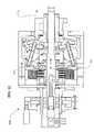
- FIG. 1is a cutaway side view of an embodiment of the transmission shifted into high.
- FIG. 2is a cutaway side view of the transmission of FIG. 1 shifted into low.
- FIG. 3is a partial end cross-sectional view of the transmission taken on line III-III of FIG. 1 .
- FIG. 4is a schematic cutaway side view of the idler and ramp sub-assembly of the transmission of FIG. 1 .
- FIG. 5is a schematic perspective view of the ball sub-assembly of the transmission of FIG. 1 .
- FIG. 6is a schematic view of the shift rod sub-assembly of the transmission of FIG. 1 .
- FIG. 7is a schematic cutaway side view of the cage sub-assembly of the transmission of FIG. 1 .
- FIG. 8is a cutaway side view of the output disc of the transmission of FIG. 1 .
- FIG. 9is a cutaway side view of an alternative embodiment of the transmission of FIG. 1 with an integrated electric motor.
- FIG. 10is a partial cutaway perspective view of the transmission of FIG. 9 .
- FIG. 11is a cutaway end view of the transmission of FIG. 9 taken on line III-III of FIG. 9 .
- FIG. 12shows the electrical and mechanical powerpath of the transmission of FIG. 9 .
- FIG. 13shows the reverse of the electrical and mechanical powerpath of the transmission of FIG. 9 .
- FIG. 14is a partial cutaway side view of the idler assembly of the transmission of FIG. 9 .
- FIG. 15is a partial schematic perspective view of the idler assembly of the transmission of FIG. 9 .
- FIG. 16is a partial cutaway perspective view of the spline assembly of the transmission of FIG. 9 .
- FIG. 17is a perspective view of the stator mount of the transmission of FIG. 9 .
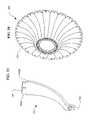
- FIG. 18is a perspective view of a lamination of the transmission of FIG. 9 .
- FIG. 19is a perspective view of the winding of the transmission of FIG. 9 .
- FIG. 20is a perspective view of the rotor of the transmission of FIG. 9 .
- FIG. 21is a perspective view of the shift screw of the transmission of FIG. 9 .
- FIG. 22is a perspective view of a partial shifter assembly of the transmission of FIG. 9 .
- FIG. 23is a cutaway side view of a transmission which can receive input power through three paths.
- FIG. 24is a cutaway perspective view of the rotor of the transmission of FIG. 23 .
- FIG. 25is a cutaway side view of a transmission with an integrated generator.
- FIG. 26is a perspective schematic view of the generator of the transmission of FIG. 25 .
- FIG. 27is a perspective of a stator of the transmission of FIG. 25 .
- FIG. 28is a perspective view of an axle of the transmission of FIG. 25 .
- FIG. 29is a perspective schematic view of the transmission of FIG. 9 with an integrated electric motor.
- FIG. 30is a sketch of the magnetic poles of a ball of the motor of FIG. 29 .
- FIG. 31is a cutaway side view of an alternative electric motor of the transmission of FIG. 9 .
- FIG. 32is a perspective view of the rotor and stator of the electric motor of FIG. 31 .
- FIG. 33is a perspective view of the conductor of the electric motor of FIG. 31 .
- FIG. 34is a perspective view of the stator of the electric motor of FIG. 31 .
- FIG. 35is a schematic end view of the stator of the electric motor of FIG. 31 showing the current path.
- FIG. 36is an alternative embodiment of the conductor of the electric motor of FIG. 31 .
- FIG. 37is an alternative embodiment of the stator of the electric motor of FIG. 31 .
- FIG. 38is a cutaway side view of an alternative embodiment of the transmission of FIG. 23 .
- the transmissions described hereinare of the type that utilize speed adjuster balls with axes that tilt as described in U.S. Pat. Nos. 6,241,636, 6,322,475, and 6,419,608, which patents are hereby incorporated herein by reference.
- the embodiments described in these patents and those described hereintypically have two sides generally separated by a variator portion, to be described below, an input side and an output side.
- the driving side of the transmissionthat is, the side that receives the torque into the transmission
- the driven side of the transmissionor the side that transfers the torque from the transmission out of the transmission
- An input disc and an output discare in contact with the speed adjuster balls.
- the point of rolling contact on one discmoves toward the pole or axis of the ball, where it contacts the ball at a circle of decreasing diameter, and the point of rolling contact on the other disc moves toward the equator of the ball, thus contacting the disc at a circle of increasing diameter.
- the input and output discsrespectively experience the converse relationship. In this manner, the ratio of rotational speed of the input disc to that of the output disc, or the transmission ratio, can be changed over a wide range by simply tilting the axes of the speed adjuster balls.
- the centers of the ballsdefine the border between the input side and the output side of the transmission and similar components that are located on both the input side of the balls and the output side of the balls are generally described herein with the same reference numbers. Similar components located on both the input and output sides of the transmission generally have the suffix “a” attached at the end of the reference number if they are located on the input side, and the components located on the output side of the transmission generally have the suffix “b” attached at the end of their respective reference numbers.
- an embodiment of a transmission 100having a longitudinal axis 11 about which multiple speed adjusting balls 1 are radially distributed.
- the speed adjusting balls 1 of some embodimentsstay in their angular positions about the longitudinal axis 11 , while in other embodiments the balls 1 are free to orbit about the longitudinal axis 11 .
- the balls 1are contacted on their input side by an input disc 34 and on their output side by an output disc 101 .
- the input and out put discs 34 , 101are annular discs extending from an inner bore near the longitudinal axis on their respective input and output sides of the balls 1 to a radial point at which they each make contact with the balls 1 .
- the input and output discs 34 , 101each have a contact surface that forms the contact area between each disc 34 and 101 , and the balls 1 .
- each portion of the contact area of the input disc 34rotates and sequentially contacts each of the balls 1 during each rotation. This is similar for the output disc 101 as well.
- the input disc 34 and the output disc 101can be shaped as simple discs or can be concave, convex, cylindrical or any other shape, depending on the configuration of the input and output desired. In one embodiment the input and output discs are spoked to make them lighter for weight sensitive applications.
- the rolling contact surfaces of the discs where they engage the speed adjuster ballscan have a flat, concave, convex or other shaped profile, depending on the torque and efficiency requirements of the application. A concave profile where the discs contact the balls decreases the amount of axial force required to prevent slippage while a convex profile increases efficiency. Additionally, the balls 1 all contact an idler 18 on their respective radially innermost point.
- the idler 18is a generally cylindrical component that rests coaxially about the longitudinal axis 11 and assists in maintaining the radial position of the balls 1 .
- the contact surfaces of the input disc 34 and the output disc 101can be located generally radially outward from the center of the balls 1 , with the idler 18 located radially inward from the balls 1 , so that each ball 1 makes three-point contact with the idler 18 , the input disc 34 , and the output disc 101 .
- the input disc 34 , the output disc 101 , and the idler 18can all rotate about the same longitudinal axis 11 in many embodiments, and are described in fuller detail below.
- transmissions 100 described hereinare rolling traction transmissions
- high axial forcesare required to prevent slippage of the input disc 34 and output disc 101 at the ball 1 contacts.
- deformation of the contact patches where the input disc 34 , the output disc 101 , and the idler 18 contact the balls 1becomes a significant problem, reducing efficiency and the life of these components.
- the amount of torque that can be transferred through these contact patchesis finite and is a function of the yield strength of the material from which the balls 1 , the input disc, 34 , the output disc 101 , and the idler 18 are made.
- the friction coefficient of the balls 1 , the input disc, 34 , the output disc 101 , and the idler 18has a dramatic effect on the amount of axial force required to transfer a given amount of torque and thus greatly affects the efficiency and life of the transmission.
- the friction coefficient of the rolling elements in a traction transmissionis a very important variable affecting performance.
- Certain coatingsmay be applied to the surfaces of the balls 1 , the input disc, 34 , the output disc 101 , and the idler 18 to improve their performance.
- such coatingscan be used advantageously on the rolling contacting elements of any rolling traction transmission to achieve the same added benefits that are achieved for the embodiments of transmissions described herein.
- Some coatingshave the beneficial effect of increasing the friction coefficient of the surfaces of these rolling elements.
- Some coatingshave a high friction coefficient and display a variable coefficient of friction, which increases as axial force increases. A high friction coefficient allows less axial force to be required for a given torque, thereby increasing efficiency and life of the transmission.
- a variable coefficient of frictionincreases the maximum torque rating of the transmission by decreasing the amount of axial force required to transfer this maximum torque.
- Some coatingspossess excellent hardness and wear properties, and can greatly extend the life of the highly loaded rolling elements in a rolling traction transmission.
- a ceramic coatingsuch as silicon nitride can have a high friction coefficient, a variable coefficient of friction which increases as axial force increases, and can also increase the life of the balls 1 , the input disc, 34 , the output disc 101 , and the idler 18 when applied to the surfaces of these components in a very thin layer.
- the coating thicknessdepends on the material used for the coating and can vary from application to application but typically is in the range of 0.5 microns to 2 microns for a ceramic and 0.75 microns to 4 microns for a cermet.
- the process used to apply the coatingis important to consider when the balls 1 , the input disc, 34 , the output disc 101 , and the idler 18 are made from hardened steel, which is the material used in many embodiments of the transmissions described herein.
- Some processes used to apply ceramics and cermetsrequire high temperatures and will lower the hardness of the balls 1 , the input disc, 34 , the output disc 101 , and the idler 18 , harming performance and contributing to premature failure.
- a low temperature application processis desirable and several are available, including low temperature vacuum plasma, DC pulsed reactive magnetron sputtering, plasma-enhanced chemical vapor deposition (PE-CVD), unbalanced magnetron physical vapor deposition, and plating.
- the plating processis attractive due to its low cost and because a custom bath can be created to achieve desired coating properties.
- Immersing the rolling elements in a bath of silicon carbide or silicon nitride with co-deposited electroless nickel or electroplated nickel with silicon carbide or silicon nitrideis a low temperature solution that is well suited for high volume production. It should be noted that other materials can be used in addition to those mentioned.
- the partsare contained in a cage, immersed in the bath, and shaken so that the solution contacts all surfaces. Thickness of the coating is controlled by the length of time that the components are immersed in the bath.
- some embodimentswill soak the components using silicon nitride with co-deposited electroless nickel for four (4) hours to achieve the proper coating thickness, although this is just an example and many ways to form the coating and control its thickness are known and can be used taking into account the desired properties, the desired thickness and the substrate or base metal of which the components are made.
- FIGS. 1 , 2 , and 3illustrate an embodiment of a continuously variable transmission 100 that is shrouded in a case 40 which protects the transmission 100 , contains lubricant, aligns components of the transmission 100 , and absorbs forces of the transmission 100 .
- a case cap 67can, in certain embodiments, cover the case 40 .
- the case cap 67is generally shaped as a disc with a bore, through its center through which an input shaft passes, and that has a set of threads at its outer diameter that thread into a corresponding set of threads on the inner diameter of the case 40 .
- the case cap 67can be fastened to the case 40 or held in place by a snap ring and corresponding groove in the case 40 , and would therefore not need to be threaded at its outer diameter.
- the case cap 67extends to the inside diameter of the case 40 so that case fasteners (not shown) used to bolt the case 40 to the machinery to which the transmission 100 is attached can be passed through corresponding holes in the case cap 67 .
- the case cap 67 of the illustrated embodimenthas a cylindrical portion extending from an area near its outer diameter toward the output side of the transmission 100 for additional support of other components of the transmission 100 .
- the transmission 100 embodimentis a plurality of balls 1 that are typically spherical in shape and are radially distributed substantially evenly or symmetrically about the centerline, or longitudinal axis 11 of rotation of the transmission 100 .
- eight balls 1are used.
- the transmissionmay include 3, 4, 5, 6, 7, 8, 9, 10, 11, 12, 13, 14, 15 or more balls.
- the provision for more than 3, 4, or 5 ballscan more widely distribute the forces exerted on the individual balls 1 and their points of contact with other components of the transmission 100 and can reduce the force necessary to prevent the transmission 100 from slipping at the ball 1 contact patches.
- Certain embodiments in applications with low torque but a high transmission ratiouse few balls 1 of relatively larger diameters, while certain embodiments in applications with high torque and a high transmission ratio can use more balls 1 or relatively larger diameters.
- certain embodiments, in applications with low torque and where high efficiency is not importantuse few balls 1 of relatively smaller diameters.
- Ball axles 3are inserted through holes that run through the center of each of the balls 1 to define an axis of rotation for each of the balls 1 .
- the ball axles 3are generally elongated shafts over which the balls 1 rotate, and have two ends that extend out of either side of the hole through the balls 1 .
- Certain embodimentshave cylindrically shaped ball axles 3 , although any shape can be used.
- the balls 1are mounted to rotate freely about the ball axles 3 .
- bearingsare utilized to reduce the friction between the outer surface of the ball axles 3 and the surface of the bore through the corresponding ball 1 .
- These bearingscan be any type of bearings situated anywhere along the contacting surfaces of the balls 1 and their corresponding ball axles 3 , and many embodiments will maximize the life and utility of such bearings through standard mechanical principles common in the design of dynamic mechanical systems.
- radial bearingsare located at each end of the bore through the balls 1 .
- These bearingscan incorporate the inner surface of the bore or the outer surface of the ball axles 3 as their races, or the bearings can include separate races that fit in appropriate cavities formed in the bore of each ball 1 and on each ball axle 3 .
- a cavity (not shown) for a bearingis formed by expanding the bore through each ball 1 at least at both ends an appropriate diameter such that a radial bearing, roller, ball or other type, can be fitted into and held within the cavity thus formed.
- the ball axles 3are coated with a friction reducing material such as babbit, Teflon or other such material.
- Many embodimentsalso minimize the friction between the ball axles 3 and the balls 1 by introducing lubrication in the bore of the ball axles 3 .
- the lubricationcan be injected into the bore around the ball axles 3 by a pressure source, or it can be drawn into the bore by the rifling or helical grooves formed on the ball axles 3 themselves. Further discussion of the lubrication of the ball axles 3 is provided below.
- FIG. 1the axes of rotation of the balls 1 are shown tilted in a direction that puts the transmission in a high ratio, wherein the output speed is greater than the input speed. If the ball axles 3 are horizontal, that is parallel to the main axis of the transmission 100 , the transmission 100 is in a 1:1 input rotation rate to output rotation rate ratio, wherein the input and output rotation speeds are equal.
- FIG. 2the axes of rotation of the balls 1 are shown tilted in a direction where the transmission 100 is in a low ratio, meaning the output rotation speed is slower than the input rotation speed. For the purpose of simplicity, only the parts that change position or orientation when the transmission 100 is shifted are numbered in FIG. 2 .
- FIGS. 1 , 2 , 4 , and 5illustrate how the axes of the balls 1 can be tilted in operation to shift the transmission 100 .
- a plurality of legs 2which in most embodiments are generally struts, are attached to the ball axles 3 near each of the ends of the ball axles 3 that extend beyond the ends of the holes bored through the balls 1 .
- Each leg 2extends from its point of attachment to its respective ball axle 3 radially inward toward the axis of the transmission 100 .
- each of the legs 2has a through bore that receives a respective end of one of the ball axles 3 .
- the ball axles 3preferably extend through the legs 2 such that they have an end exposed beyond each leg 2 .
- the ball axles 3advantageously have rollers 4 coaxially and slidingly positioned over the exposed ends of the ball axles 3 .
- the rollers 4are generally cylindrical wheels fitted over the ball axles 3 outside of and beyond the legs 2 and rotate freely about the ball axles 3 .
- the rollers 4can be attached to the ball axles 3 via spring clips or other such mechanism, or they can ride freely over the ball axles 3 .
- the rollers 4can be radial bearings for instance, where the outer races of the bearings form the wheel or rolling surface. As illustrated in FIGS. 1 and 7 , the rollers 4 and the ends of the ball axles 3 fit inside grooves 86 formed by or in a pair of stators 80 a , 80 b.
- the stators 80 a , 80 b of one embodimentare illustrated in FIGS. 5 and 7 .
- the illustrated input stator 80 a and output stator 80 bare generally in the form of parallel discs annularly located about the longitudinal axis 11 of the transmission on either side of the balls 1 .
- the stators 80 a , 80 b of many embodimentsare comprised of input stator discs 81 a and output stator discs 81 b , respectively, which are generally annular discs of substantially uniform thickness with multiple apertures to be discussed further below.
- Each input and output stator disc 81 a , 81 bhas a first side that faces the balls 1 and a second side that faces away from the balls 1 .
- stator curves 82are attached to the first side of the stator discs 81 a , 81 b .
- the stator curves 82are curved surfaces attached or affixed to the stator discs 81 a , 81 b that each has a concave face 90 facing toward the balls 1 and a convex face 91 facing away from the balls 1 and contacting their respective stator discs 81 .
- the stator curves 82are integral with the stator discs 81 a , 81 b .
- the stator curves 82 of many embodimentshave a substantially uniform thickness and have at least one aperture (not separately shown) used to align and attach the stator curves 82 to each other and to the stator discs 81 .
- the stator curves 82 of many embodiments, or the stator discs 81 a , 81 b where integral parts are used,include a slot 710 that accepts a flat spacer 83 , which allows further positioning and alignment of the stator curves 82 and stator discs 81 a , 81 b .
- the flat spacers 83are generally flat and generally rectangular pieces of rigid material that extend between and interconnect the input stator 80 a and the output stator 80 b .
- the flat spacers 83fit within the slots 710 formed in the stator curves 82 .
- the flat spacers 83are not fastened or otherwise connected to the stator curves 82 ; however, in some embodiments the flat spacers 83 are attached to the stator curves 82 by welding, adhesive, or fastening.
- multiple cylindrical spacers 84of a generally cylindrical shape with bores at least in each end, are radially positioned inside of the flat spacers 83 and also connect and position the stator discs 81 and stator curves 82 .
- the bores of the cylindrical spacers 84accept one spacer fastener 85 at each end.
- the spacer fasteners 85are designed to clamp and hold the stator discs 81 a , 81 b , the stator curves 82 , the flat spacers 83 , and the cylindrical spacers 84 together, which collectively form the cage 89 .
- the cage 89maintains the radial and angular positions of the balls 1 and aligns the balls 1 with respect to one another.
- the rotational axes of the balls 1are changed by moving either the input-side or output-side legs 2 radially out from the axis of the transmission 100 , which tilts the ball axles 3 .
- each roller 4fits into and follows a groove 86 , which is slightly larger than the diameter of the roller 4 , and is formed by the space between each pair of adjacent stator curves 82 .
- the rollers 4therefore roll along the surface of the sides 92 , 93 of the stator curves 82 , a first side 92 and a second side 93 for each stator curve 82 , in order to maintain the plane of movement of the ball axles 3 in line with the longitudinal axis 11 of the transmission 100 .
- each roller 4rolls on a first side 92 of the stator curve 82 on the input side of the transmission 100 and on the corresponding first side 92 of the corresponding output stator curve 82 .
- the forces of the transmission 100prevent the rollers 4 from contacting the second side 93 of the stator curves 82 in normal operation.
- the rollers 4are slightly smaller in diameter than the width of the grooves 86 formed between the stator curves 82 , forming a small gap between the edges of the grooves 86 and the circumference of each corresponding roller.
- stator curves 82 on the input stator 80 a and output stator 80 bwere in perfect alignment, the small gap between the circumferences of the rollers 4 and the grooves 86 would allow the ball axles to slightly tilt and become misaligned with the longitudinal axis 11 of the transmission 100 . This condition produces sideslip, a situation where the balls axles 3 are allowed to move slightly laterally, which lowers overall transmission efficiency.
- the stator curves 82 on the input and output sides of the transmission 100may be slightly offset from each other so that the ball axles 3 remain parallel with the axis of the transmission 100 .
- any tangential force, mainly a transaxial force, the balls 1 may apply to the ball axles 3is absorbed by the ball axles 3 , the rollers 4 and the first sides 92 , 93 of the stator curves 82 .
- the transmission 100is shifted to a lower or higher transmission ratio by changing the rotational axes of the balls 1 , each one of the pairs of rollers 4 , located on the opposite ends of a single ball axle 3 , move in opposite directions along their respective corresponding grooves 86 by rolling up or down a respective side of the groove 86 .
- the cage 89can be rigidly attached to the case 40 with one or more case connectors 160 .
- the case connectors 160extend generally perpendicularly from the radial outermost part of the flat spacers 83 .
- the case connectors 160can be fastened to the flat spacers 83 or can be formed integrally with the flat spacers 83 .
- the outside diameter formed roughly by the outsides of the case connectors 160is substantially the same dimension as the inside diameter of the case 40 and holes in both the case 40 and case connectors 160 provide for the use of standard or specialty fasteners, which rigidly attach the case connectors 160 to the case 40 , thus bracing and preventing the cage 40 from moving.
- the case 40has mounting holes providing for the attachment of the case 40 to a frame or other structural body.
- the case connectors 160can be formed as part of the case 40 and provide a location for attachment of the flat spacers 83 or other cage 89 component in order to mobilize the cage 89 .
- FIGS. 1 , 5 , and 7illustrate an embodiment including a pair of stator wheels 30 attached to each of the legs 2 that roll on the concave face 90 of the curved surfaces 82 along a path near the edge of the sides 92 , 93 .
- the stator wheels 30are attached to the legs 2 generally in the area where the ball axles 3 pass through the legs 2 .
- the stator wheels 30can be attached to the legs 2 with stator wheel pins 31 , which pass through a bore through the legs 2 that is generally perpendicular to the ball axles 3 , or by any other attachment method.
- the stator wheels 30are coaxially and slidingly mounted over the stator wheel pins 31 and secured with standard fasteners, such as snap rings for example.
- the stator wheels 30are radial bearings with the inner race mounted to the stator wheel pins 31 and the outer race forming the rolling surface.
- one stator wheel 30is positioned on each side of a leg 2 with enough clearance from the leg 2 to allow the stator wheels 30 to roll radially along the concave faces 90 , with respect to the longitudinal axis 11 of the transmission 100 , when the transmission 100 is shifted.
- the concave faces 90are shaped such that they are concentric about a radius from the longitudinal axis 11 of the transmission 100 formed by the center of the balls 1 .
- guide wheels 21are illustrated that can be attached to the end of the legs 2 that are nearest the longitudinal axis 11 of the transmission 100 .
- the guide wheels 21are inserted into a slot formed in the end of the legs 2 .
- the guide wheels 21are held in place in the slots of the legs 21 with guide wheel pins 22 , or by any other attachment method.
- the guide wheels 21are coaxially and slidingly mounted over the guide wheel pins 22 , which are inserted into bores formed in the legs 2 on each side of the guide wheels 21 and perpendicular to the plane of the slot.
- the legs 2are designed to deflect elastically relatively slightly in order to allow for manufacturing tolerances of the parts of the transmission 100 .
- the ball 1 , the legs 2 , the ball axle 3 , the rollers 4 , the stator wheels 30 , the stator wheel pins 31 , the guide wheels 21 , and the guide wheel pins 22collectively form the ball/leg assembly 403 seen in FIG. 5 .
- shiftingis actuated by rotating a rod 10 that is positioned outside of the case 40 .
- the rod 10is utilized to wrap an unwrap a flexible input cable 155 a and a flexible output cable 155 b that are attached to, at their respective first ends, and wrapped around the rod 10 , in opposite respective directions.
- the input cable 155 ais wrapped counter-clockwise around the rod 10 and the output cable 155 b is wrapped clockwise around the rod 10 , when looking from right to left as the rod 10 is illustrated in FIG. 6 .
- Both the input cable 155 a and the output cable 155 bextend through holes in the case 40 and then through the first end of an input flexible cable housing 151 a , and an output flexible cable housing 151 b .
- the input flexible cable housing 151 a and the output flexible cable housing 151 b of the illustrated embodimentare flexible elongated tubes that guide the input cable 155 a and output cable 155 b radially inward toward the longitudinal axis 11 then longitudinally out through holes in the stator discs 81 a, b and then again radially inward where the second end of the input and output flexible cable housings 151 a, b are inserted into and attach to the first end of input and output rigid cable housings 153 a, b , respectively.
- the input and output rigid cable housings 153 a, bare inflexible tubes through which the cables 155 a, b , pass and are guided radially inward from the second ends of the flexible cable housings 151 a, b and then direct the cables 155 a, b longitudinally through holes in the stator discs 81 a, b and toward a second end of the rigid cable housings 153 a, b near the idler 18 .
- the cables 155 a, bare attached at their second ends to an input shift guide 13 a , and an output shift guide 13 b (described further below) with conventional cable fasteners, or other suitable attachment means.
- the shift guides 13 a , 13 bposition the idler 18 axially along the longitudinal axis 11 and position the legs 3 radially, thereby changing the axes of the balls 1 and the ratio of the transmission 100 .
- the input cable 155 aunwinds from the rod 10 and the output cable 155 b winds onto the rod 10 . Therefore, the second end of the output cable 155 b applies a tension force to the output shift guide 13 b and the input cable 155 a is unwinding a commensurate amount from the rod 10 . This moves the idler 18 axially toward the output side of the transmission 100 and shifts the transmission 100 toward low.
- the illustrated shift guides 13 a, bare each generally of the form of an annular ring with inside and outside diameters, and are shaped so as to have two sides.
- the first sideis a generally straight surface that dynamically contacts and axially supports the idler 18 via two sets of idler bearings 17 a , 17 b , which are each associated with a respective shift guide 13 a, b .
- each shift guide 13 a, bis a cam side that transitions from a straight or flat radial surface 14 , towards the inner diameter of the shift guides 13 a, b , to a convex curve 97 towards the outer diameter of the shift guides 13 a, b .
- a longitudinal tubular sleeve 417 a , bextends axially toward the opposing shift guide 13 a, b in order to mate with the tubular sleeve 417 a, b from that shift guide 13 a, b .
- the tubular sleeve of the input side shift guide 13 ahas part of its inner diameter bored out to accept the tubular sleeve of the output shift guide 13 b .
- a portion of the outer diameter of the tubular sleeve of the output shift guide 13 bhas been removed to allow a portion of that tubular sleeve 417 a, b to be inserted into the tubular sleeve 417 a, b of the input shift guide 13 a .
- Thisprovides additional stability to the shift guides 13 a, b of such embodiments.
- the cross section side view of the shift guides 13 a, b illustrated in FIG. 4shows that, in this embodiment, the flat surface 14 profile of the side facing away from the is perpendicular to the longitudinal axis 11 up to a radial point where the guide wheels 21 contact the shift guides 13 a, b , if the ball axles 3 are parallel with the longitudinal axis 11 of the transmission 100 . From this point moving out toward the perimeter of the shift guide 13 a, b the profile of the shift guides 13 a, b curves in a convex shape.
- the convex curve 97 of a shift guide 13 a, bis not a radius but is composed of multiple radii, or is shaped hyperbolically, asymptotically or otherwise.
- the shift guides 13 a, bcan be attached to each other by either threading the tubular sleeve of the input shift guide 13 a with male threads and the tubular sleeve of the output sleeve 13 b with female threads, or vice versa, and threading the shift guides 13 a, b , together.
- One shift guide 13 a, bcan also be pressed into the other shift guide 13 a, b .
- the shift guides 13 a, bcan also be attached by other methods such as glue, metal adhesive, welding or any other means.
- the convex curves 97 of the two shift guides 13 a, bact as cam surfaces, each contacting and pushing the multiple guide wheels 21 .
- the flat surface 14 and convex curve 97 of each shift guide 13 a, bcontact the guide wheels 21 so that as the shift guides 13 a, b , move axially along the longitudinal axis 11 , the guide wheels 21 ride along the shift guide 13 a, b surface 14 , 97 in a generally radial direction forcing the leg 2 radially out from, or in toward, the longitudinal axis 11 , thereby changing the angle of the ball axle 3 and the rotational axis of the associated ball 1 .
- the idler 18 of some embodimentsis located in a trough formed between the first sides and the sleeve portions of the shift guides 13 a, b , and thus moves in unison with the shift guides 13 a, b .
- the idler 18is generally tubular and of one outside diameter and is substantially cylindrical along the central portion of its inside diameter with an input and output idler bearing 17 a, b , on each end of its inside diameter.
- the outer diameter and inside diameters of the idler 18can be non-uniform and can vary or be any shape, such as ramped or curved.
- the idler 18has two sides, one near the input stator 80 a , and one near the output stator 80 b .
- the idler bearings 17 a , 17 bprovide rolling contact between the idler 18 and the shift guides 13 a, b .
- the idler bearings 17 a , 17 bare located coaxially around the sleeve portion of the shift guides 13 a, b , allowing the idler 18 to rotate freely about the axis of the transmission 100 .
- a sleeve 19is fit around the longitudinal axis 11 of the transmission 100 and fitting inside the inside diameters of the shift guides 13 a, b .
- the sleeve 19is a generally tubular component that is held in operable contact with an inside bearing race surface of each of the shift guides 13 a, b by an input sleeve bearing 172 a and an output sleeve bearing 172 b .
- the sleeve bearings 172 a, bprovide for rotation of the sleeve 19 by rolling along an outer bearing race complimentary to the races of the shift guides 13 a, b .
- the idler 18 , the idler bearings 17 a , 17 b , the sleeve 19 , the shift guides 13 a , 13 b , and the sleeve bearings 172 a , 172 bcollectively form the idler assembly 402 , seen in FIG. 4 .
- the sleeve 19 of some embodimentshas its inside diameter threaded to accept the threaded insertion of an idler rod 171 .
- the idler rod 171is a generally cylindrical rod that lies along the longitudinal axis 11 of the transmission 100 .
- the idler rod 171is threaded at least partially along its length to allow insertion into the sleeve 19 .
- the first end of the idler rod 171which faces the output side of the transmission 100 , is preferably threaded through the sleeve 19 and extends out past the output side of the sleeve 19 where it is inserted into the inside diameter of the output disc 101 .
- the output disc 101in some embodiments is generally a conical disc that is spoked to reduce weight and has a tubular sleeve portion extending from its inner diameter axially toward the output side of the transmission 100 .
- the output disc 101transfers the output torque to a drive shaft, wheel, or other mechanical device.
- the output disc 101contacts the balls 1 on their output side and rotates at a speed different from the input rotation of the transmission at ratios other than 1:1.
- the output disc 101serves to guide and center the idler rod 171 at its first end so that the sleeve 19 , idler 18 , and shift guides 13 a, b stay concentric with the axis of the transmission 100 .
- annular bearingmay be positioned over the idler rod 171 , between the idler rod 171 and the inside diameter of the output disc 101 , to minimize friction.
- the idler rod 171 , sleeve 19 , shift guides 13 a, b , and idler 18are operably connected, and all move axially in unison when the transmission 100 is shifted.
- a conical spring 133positioned between the input shift guide 13 a and stator 80 a biases the shifting of the transmission 100 toward low.
- output disc bearings 102which contact a bearing race near the perimeter of the output disc 101 , absorb and transfer axial force generated by the transmission 100 to the case 40 .
- the case 40has a corresponding bearing race to guide the output disc bearings 102 .
- the limits of the axial movement of the shift guides 13 a, bdefine the shifting range of the transmission 100 .
- Axial movementis limited by inside faces 88 a, b , on the stator discs 81 a, b , which the shift guides 13 a, b , contact.
- shift guide 13 acontacts the inside face 88 a on the input stator discs 81 a
- the shift guide 13 bcontacts the inside face 88 on the output stator disc 81 b .
- the curvature of the convex curves 97 of the shift guides 13 a, bis functionally dependent on the distance from the center of a ball 1 to the center of the guide wheel 21 , the radius of the guide wheel 21 , the angle between lines formed between the two guide wheels 21 and the center of the ball 1 , and the angle of tilt of the ball 1 axis.
- An example of such a relationshipis described below, with respect to FIGS. 25 , 26 and 27 .
- one or more stator wheels 30can be attached to each leg 2 with a stator wheel pin 31 that is inserted through a hole in each leg 2 .
- the stator wheel pins 31are of the proper size and design to allow the stator wheels 30 to rotate freely over each stator wheel pin 31 .
- the stator wheels 30roll along the concave curved surfaces 90 of the stator curves 82 that face the balls 1 .
- the stator wheels 30provide axial support to prevent the legs 2 from moving axially and to ensure that the ball axles 3 tilt easily when the transmission 100 is shifted.
- a spoked input disc 34located adjacent to the stator 80 a , partially encapsulates but generally does not contact the stator 80 a .
- the input disc 34may have two or more spokes or may be a solid disc. The spokes reduce weight and aid in assembly of the transmission 100 . In other embodiments, a solid disc can be used.
- the input disc 34has two sides, a first side that contacts with the balls 1 , and a second side that faces opposite the first side.
- the input disc 34is generally an annular disk that fits coaxially over, and extends radially from, a set of female threads or nut 37 at its inner diameter.
- the outside diameter of the input disc 34is designed to fit within the case 40 , if the case 40 used is the type that encapsulates the balls 1 and the input disc 34 and mounts to a rigid support structure 116 such as a chassis or frame with conventional bolts, which are inserted through bolt holes in a flange on the case 40 .
- the input disc 34is in rotating contact with the balls 1 along a circumferential ramped or bearing contact surface on a lip of the first side of the input disc 34 , the side facing the balls 1 .
- some embodiments of the input disc 34have a set of female threads 37 , or a nut 37 , inserted into its inside diameter, and the nut 37 is threaded over a screw 35 , thereby engaging the input disc 34 with the screw 35 .
- the screw 35is attached to and rotated by a drive shaft 69 .
- the drive shaft 69is generally cylindrical and has an inner bore, a first end facing axially towards the output side, a second end facing axially toward the input side, and a generally constant diameter.
- the drive shaft 69is rigidly attached to and rotated by the input torque device, usually a gear, a sprocket, or a crankshaft from a motor.
- the drive shaft 69has axial splines 109 extending from its second end to engage and rotate a corresponding set of splines formed on the inside diameter of the screw 35 .
- a set of central drive shaft ramps 99which on a first side is generally a set of raised inclined surfaces on an annular disk that is positioned coaxially over the drive shaft 69 , have mating prongs that mate with the splines 109 on the drive shaft 99 , are rotated by the drive shaft 69 , and are capable of moving axially along the drive shaft 69 .
- a pin ring 195contacts a second side of the central drive shaft ramps 99 .
- the pin ring 195is a rigid ring that is coaxially positioned over the idler rod 171 , is capable of axial movement and has a transverse bore that functions to hold an idler pin 196 in alignment with the idler rod 171 .
- the idler pin 196is an elongated rigid rod that is slightly longer than the diameter of the pin ring 195 and which is inserted through an elongated slot 173 in the idler rod 171 and extends slightly beyond the pin ring 195 at both its first and second ends when it is inserted into the bore of the pin ring 195 .
- the elongated slot 173 in the idler rod 171allows for axial movement of the idler rod 171 to the right, when viewed as illustrated in FIG. 1 , without contacting the pin 196 when the transmission 100 is shifted from 1:1 toward high.
- the side on the input end of the elongated slot 173contacts the pin 196 , which then operably contacts the central drive shaft ramps 99 via the pin ring 195 .
- the idler rod 171is thus operably connected to the central drive shaft ramps 99 when the transmission is between 1:1 and low so that when the idler rod 171 moves axially the central drive shaft ramps 99 also move axially in conjunction with the idler rod 171 .
- the ramp surfaces of the central drive shaft ramps 99can be helical, curved, linear, or any other shape, and are in operable contact with a set of corresponding central bearing disc ramps 98 .
- the central bearing disc ramps 98have ramp faces that are complimentary to and oppose the central drive shaft ramps 99 .
- the central bearing disc ramps 98face the central drive shaft ramps 99 and are contacted and driven by the central drive shaft ramps 99 .
- the central bearing disc ramps 98are rigidly attached to a bearing disc 60 , a generally annular disc positioned to rotate coaxially about the longitudinal axis 11 of the transmission 100 .
- the bearing disc 60has a bearing race near its perimeter on its side that faces away from the balls 1 that contacts a bearing disc bearing 66 .
- the bearing disc bearing 66is an annular thrust bearing at the perimeter of the bearing disc 60 and is positioned between the bearing disc 60 and the case cap 67 .
- the bearing disc bearing 66provides axial and radial support for the bearing disc 60 and in turn is supported by a bearing race on a case cap 67 , which acts with the case 40 to encapsulate partially the inner parts of the transmission 100 .
- the case cap 67is generally an annular disc extending from the drive shaft 69 having a tubular portion extending toward the output end from at or near its perimeter and also having a bore through its center.
- the case cap 67absorbs axial and radial forces produced by the transmission 100 , and seals the transmission 100 , thereby preventing lubricant from escaping and contamination from entering.
- the case cap 67is stationary and, in some embodiments, is rigidly attached to the case 40 with conventional fastening methods or can have male threads on its outside diameter, which mate with corresponding female threads on the inside diameter of the case 40 .
- the case cap 67has a bearing race that contacts the bearing disc bearing 66 near the perimeter of the bearing disc 60 that is located at the inside of the output end of the tubular extension from the case cap 67 .
- the case cap 67also has a second bearing race facing the output side located near the inside diameter of its annular portion that mates with a drive shaft bearing 104 .
- the drive shaft bearing 104is a combination thrust and radial bearing that provides axial and radial support to the drive shaft 69 .
- the drive shaft 67has a bearing race formed on its outside diameter facing the input side that mates with the drive shaft bearing 104 , which transfers the axial force produced by the screw 35 to the case cap 67 .
- An input bearing 105adds support to the drive shaft 69 .
- the input bearing 105is coaxially positioned over the drive shaft 69 and mates with a third race on the inside diameter of the case cap 67 facing the input side of the transmission 100 .
- a cone nut 106a generally cylindrical threaded nut with a bearing race designed to provide a running surface for the input bearing 105 , is threaded over the drive shaft 69 and supports the input bearing 105 .
- a set of multiple perimeter ramps 61are rigidly attached to the bearing disc 60 .
- the perimeter ramps 61are multiple inclined surfaces that are positioned radially about the longitudinal axis 11 and are positioned against or formed on the bearing disc 60 and face the output side.
- the inclined surfacescan be curved, helical, linear, or another shape and each one creates a wedge that produces and axial force that is applied to one of multiple ramp bearings 62 .
- the ramp bearings 62are spherical but can be cylindrical, conical, or another geometric shape, and are housed in a bearing cage 63 .
- the bearing cage 63 of the illustrated embodimentis generally ring shaped with multiple apertures that contain the individual ramp bearings 62 .
- a set of input disc ramps 64are rigidly attached to, or formed as part of, the input disc 34 .
- the input disc ramps 64in some embodiments are complimentary to the perimeter ramps 62 with the ramps facing toward the input side.
- the input disc ramps 64are in the form of a bearing race that aligns and centers the ramp bearings 62 radially.
- the ramp bearings 62respond to variations in torque by rolling up or down the inclined faces of the perimeter ramps 61 and the input disc ramps 64 .
- an axial force generator 160is made up of various components that create an axial force that is generated and is applied to the input disc 34 to increase the normal contact force between the input disc 34 and the balls 1 , which is a component in the friction the input disc 34 utilizes in rotating the balls 1 .
- the transmission 100produces sufficient axial force so that the input disc 34 , the balls 1 , and the output disc 101 do not slip, or slip only an acceptable amount, at their contact points. As the magnitude of torque applied to the transmission 100 increases, an appropriate amount of additional axial force is required to prevent slippage. Furthermore, more axial force is required to prevent slippage in low than in high or at a 1:1 speed ratio.
- the axial force generator 160will vary the axial force applied to the balls 1 as the transmission 100 is shifted and as torque is varied. In some embodiments, the transmission 100 accomplishes both these goals.
- the screw 35is designed and configured to provide an axial force that is separate and distinct from that produced by the perimeter ramps 61 . In some embodiments, the screw 35 produces less axial force than the perimeter ramps 61 , although in other versions of the transmission 100 , the screw 35 is configured to produce more force than the perimeter ramps 61 .
- the screw 35Upon an increase in torque, the screw 35 rotates slightly farther into the nut 37 to increase axial force by an amount proportional to the increase in torque.
- the idler rod 171moves axially toward the input side, along with the sleeve 19 , sleeve bearings 172 , shift guides 13 a, b , and idler 18 .
- the idler rod 171contacts the central drive shaft ramps 99 through the pin 196 and pin ring 195 , causing the central drive shaft ramps 99 to move axially toward the output side.
- the ramped surfaces of the central drive shaft ramps 99contact the opposing ramped surfaces of the central bearing disc ramps 98 , causing the central bearing disc ramps 98 to rotate the bearing disc 67 and engage the perimeter ramps 61 with the ramp bearings 62 and the input disc ramps 64 .
- the central drive shaft ramps 99 and the central bearing disc ramps 98perform a torque splitting function, shifting some of the torque from the screw 35 to the perimeter ramps 61 . This increases the percentage of transmitted torque that is directed through the perimeter ramps 61 , and because the perimeter ramps 61 are torque sensitive as described above, the amount of axial force that is generated increases.
- the idler 18when shifting into low, the idler 18 moves axially towards the output side, and is pulled toward low by a reaction of forces in the contact patch. The farther the idler 18 moves toward low, the stronger it is pulled.
- the magnitude of the resultant forces from spin at the contact between the idler 18 and the balls 1is minimal in comparison to that of the balls 1 and input and output discs 34 , 101 . Due to the minimal spin produced at the contact patch of the idler 18 and ball 1 interface, this contact patch will be ignored for the following explanation. Spin can be considered an efficiency loss in the contact patches at the input disc 34 and ball 1 and at the output disc 101 and ball 1 . Spin produces a transverse force perpendicular to the rolling direction of the balls 1 and discs 34 , 101 . At a 1:1 ratio, the transverse forces produced by spin, or contact spin, at the input and output contact patches are equal and opposite and are essentially cancelled. There is no axial pull on the idler 18 in this condition.
- the contact patch at the input disc 34 and ball 1moves farther from the axis or pole of the ball 1 .
- the output disc 101 and ball 1 contact patchmoves closer to the axis or pole of the ball 1 , which increases spin and the resultant transverse force.
- the contact patch between the output disc 101 and ball 1moves closer to the axis of the ball 1 .
- the transverse forces caused by spin on the ball 1exert a force in the opposite direction when shifting into high.
- the legs 2 attached to the ball axles 3transfer the pull to the shift guides 13 a, b , and because the shift guides 13 a, b , are operably attached to the idler 18 and sleeve 19 , an axial force is transferred to the idler rod 171 .
- the influence of contact spinincreases at all ratios and efficiency decreases.
- the pull transferred to the idler rod 171results in an axial force toward the left, as viewed in FIG. 1 , which causes the input torque to shift from the screw 35 to the perimeter ramps 61 .
- the idler rod 171pulls more strongly, causing relative movement between the central drive shaft ramps 99 and the central bearing disc ramps 98 and shifts even more torque to the perimeter ramps 61 . This reduces the torque transmitted through the screw 35 and increases the torque transmitted through the perimeter ramps 61 , resulting in an increase in axial force.
- a transmission 600that incorporates an electric motor/generator 601 (MG 601 ).
- the MG 601is an 8-pole brushless DC motor with 3 stator phases.
- the MG 601can be comprised of an electrical stator 682 and an electrical rotor 694 which rotate in opposite directions.
- the speed of the MG 601is defined as the relative speed between the electrical rotor 694 and the electrical stator 682 .
- the electrical stator 682is operably attached to the idler 18 , which due to the planetary effect of the balls 1 reverses the rotation of the input disc 34 ; hence, the idler 18 rotates in the opposite direction of the input disc 34 .
- the electrical rotor 694which in some embodiments is a rotating magnetic steel cylinder and is rigidly attached to the input disc 34 , can be made from the same component as the input disc 34 , or can be made separately and joined to the input disc 34 .
- the rotor 694utilizes permanent magnets 680 annularly positioned around and attached to the inside diameter of the rotor 694 .
- the magnetic field produced by the rotor 694uses one or more electromagnets.
- the electrical stator 682is comprised of coils 684 wrapped around multiple laminations 686 that are rigidly attached to a stator mount 630 .
- the stator mount 630also positions the electrical stator 682 relative to the rotor 694 and magnets 680 , and routes the multiple wires (not shown) that connect the electrical stator 682 to the source of electricity.
- the stator mount 630is operably attached to the idler shaft 602 with a plurality of spline bearings 636 .
- the idler shaft 602is a long, cylindrically shaped shaft that is positioned at the center of the transmission 600 , is coincident with the longitudinal axis 11 , and is capable of axial movement to move the idler 18 and thus shift the transmission.
- a cable 676houses the wires of the MG 601 which are routed from the electric stator 682 , through the stator mount 630 , and terminate at a receptacle 674 inside the idler shaft 602 .
- the cylindrically shaped receptacle 674accepts three leads from the three phases of the electric stator 682 and routes the three leads to a rotating conductor 672 .
- the rotating conductor 672transfers electricity from a rotating end at the receptacle 674 to a stationary end at the conductor cap 668 .
- the rotating conductor 672is of the type that uses liquid metal, such as mercury, to transfer current from the rotating end to the stationary end.
- slip ringsare used, although any other suitable method can be employed.
- Extending from the conductor cap 668are three leads which are attached to a motor controller (not shown). The motor controller is attached to the source of electricity (not shown).
- the idler 18is positioned on the input side of the transmission 600 .
- the speed of the output disc 101decreases.
- the speed of the rotor 694increases because the rotor 694 is joined to the input disc 34 and rotates at a constant speed relative to the electrical stator 682 and the idler 18 .
- the net effectis that there is a significant speed reduction at the output disc 101 in all ratios relative to the speed of the MG 601 .
- Another benefit of the transmission 600 in combination with an electric motor 601is an increase in torque, which equals the inverse of the decrease in speed. This allows for a significantly smaller MG 601 to produce the required torque for a given application.
- Other benefits of combining the transmission 600 with the MG 601include a shared shaft, case, and bearings. Still another benefit is that in many high torque applications the input disc 34 is made from magnetic steel, and when the input disc 34 and rotor 694 are made as one part, the additional weight and cost of the magnetic steel which surrounds the magnets 680 is eliminated.
- Yet another benefitis the potential to liquid cool the electrical stator 682 using the same fluid that is in the transmission 600 . Depositing the same liquid on the electrical stator 682 provides the opportunity to put significantly more power through the MG 601 .
- a liquid cooled MG 601can utilize the same fluid, pump, hoses, and seals used in the transmission 600 .
- Another benefitis the reduced size and weight of the transmission 600 , MG 601 , and speed reducer when they are combined into one unit as compared to three separate devices. The smaller size and weight reduces inertia and allows the transmission 600 and MG 601 to fit into a smaller space than would otherwise be required. In an electric vehicle, the smaller size and weight provides more room for batteries or fuel cells.
- Still another benefitis the elimination of couplers and shafts linking the motor to the transmission to the speed reducer in a conventional electric drivetrain. Another benefit is the increased efficiency attained from reducing the required number of bearings and eliminating shaft misalignment between a motor, transmission, and speed reducer. Yet another benefit is derived from the fact that there is no mechanical input into the MG 601 , transmission 600 , or speed reducer. This provides opportunities for creative drivetrain designs, including multiple inputs and outputs.
- the rotor 694has attached to it on the input side of the transmission 600 , a side cap 612 , which can be rigidly secured to the rotor 694 using standard fasteners.
- the side cap 612is a disc shaped component that in one embodiment is made from steel although other materials can be used.
- the side cap 612serves to contain lubricant, cooling fluid, and to protect and contain the components of the transmission 600 .
- On the output side of the transmission 600 an end cap 658is attached to the rotor 694 .
- the end cap 658can be rigidly secured to the rotor 694 using standard fasteners and in one embodiment is constructed of steel, although other materials can used.
- An output disc bearing 605which can support radial loads and in some embodiments axial loads, is positioned around the outside diameter of the output disc 101 and inside a bore of the end cap 658 , and allows for relative movement between the output disc 101 and the end cap 658 .
- a cap bearing 626positioned around the idler shaft 602 and inside a bore of the side cap 612 , provides for relative movement between the rotor 694 and the idler shaft 602 , and can support radial loads and in some embodiments axial loads.
- a thrust bearing 624which serves to prevent axial movement of the side cap 612 , is positioned between the side cap 612 and a cap washer 628 .
- the cap washer 628is rigidly attached to the shift screw 622 , a stationary piece which can be mounted by standard fasteners to a rigid, non-moving structure, such as a frame or chassis, which is capable of withstanding the highest torque transferred through the transmission 600 .
- a shift nut 621is threaded over the shift screw 622 , and rotation of the shift nut 621 causes the idler shaft 602 to move axially, shifting the transmission 600 .
- the shift nut 621is a generally annularly shaped component that is threaded at a bore in its center and does not experience high torque.
- the shift nut 621is constructed from aluminum, although other materials, including plastic and steel can be used.
- the transmission 600is manually shifted, although it can be shifted automatically using the centrifugal force of the rotating components, an electric motor, or other suitable method.
- One or more handles 618can be attached to the shift nut 621 , so that the user can more easily rotate the shift nut 621 .
- the shift nut 621is attached with standard fasteners to a disc shaped shift ring 620 that has a bore in its center.
- the shift ring 620is constructed from the same material as the shift nut 621 although other materials may be used.
- the shift nut 621 and shift ring 620contain two shift bearings 652 a, b that minimize friction when the shift nut 621 and shift ring 620 rotate relative to a pin mount 650 .
- the pin mount 650is a disc shaped component with a bore at its center that provides clearance over the shift screw 622 .
- the pin mount 650 axisis concentric with the longitudinal axis 11 and is aligned by counterbores in the shift nut 621 and shift ring 620 .
- the pin mount 650has two threaded holes 180 degrees apart extending radially from its center although fewer or more threaded holes can be used.
- Two shift pins 616 a, bwhich in one embodiment are threaded into the threaded holes of the pin mount 650 , but can also be pressed, welded, or inserted using any other suitable method, are threaded pins that extend into the bore of the pin mount 650 , through slots in the shift screw 622 , and into the bore of the shift screw 622 .
- the shift pins 616 a, bcontact two pin bearings 654 a, b , which are positioned over the idler shaft 602 and inside the bore of the shift screw 622 .
- the pin bearings 654 a, bprovide relative movement between the rotating idler shaft 602 , and the shift pins 616 a, b , and absorb thrust loads which occur from shifting the transmission 600 .
- a stator bearing 614is positioned in the bore of the input stator 80 a and around the idler shaft 602 to allow for axial movement between the idler shaft 602 and the input stator 80 a , and to withstand radial loads.
- a shaft bearing 610is positioned over the idler shaft 602 and inside the bore of a stator brace 608 .
- the shaft bearing 610is a needle roller or cylindrical roller bearing where the rollers contact a hardened and polished area of the idler shaft 602 . This allows the idler shaft 602 to move axially relative to the shaft bearing 610 with minimal friction.
- the stator brace 608is a generally cylindrical component that in some embodiments is made from hardened steel, although any suitable material can be used. At a first end the stator brace 608 is rigidly attached to the cage 89 with standard fasteners, although it can be welded, pressed into a bore of the cage 89 , or formed integral with the cage 89 . At a second end the stator brace 608 is rigidly attached to a stationary structure, such as a frame or chassis. To provide relative movement between the stator brace 608 and the output disc 101 , one or more brace bearings 604 a, b are positioned over the outside diameter of the stator brace 608 and inside the bore of the output disc 101 . The brace bearings 604 a, b also support radial loads and in some embodiments axial loads.
- the idler shaft 602can be constructed of any suitable material designed to withstand the torque and speed of the transmission 600 and in some embodiments hardened steel is used, although mild steel, aluminum, titanium, carbon fiber, can also be employed.
- the idler shaft 602has formed into its outside diameter one or more shaft grooves 634 , generally longitudinal grooves that are parallel with the idler shaft 602 axis and that in some embodiments are of a radius slightly larger than the spline bearings 636 .
- the spline bearings 636are generally spherical rolling elements that transfer torque between the electrical stator 682 and the idler shaft 602 .
- the spline bearings 636can be made from hardened steel or other suitable materials. The number and size of spline bearings 636 used depends on the amount of torque which must be transferred, the radius and length of the shaft grooves 634 , and the size of the transmission 600 .
- mount grooves 632Formed into the inside diameter of the stator mount 630 are one or more mount grooves 632 , which in some embodiments are identical to the shaft grooves 634 , but in other embodiments can be longer or shorter, and also use a different radius.
- the spline bearings 636are positioned so that the center of each spline bearing 636 is halfway between the radial depth of both the shaft grooves 634 and mount grooves 632 .
- the spline bearings 636have a self centering feature in that they roll tangentially up both the radii of the shaft grooves 634 and mount grooves 632 an equal amount.
- the spline bearings 636When two or more shaft grooves 634 and mount grooves 632 are used, and when they are positioned angularly equidistant, the spline bearings 636 will center the electrical stator 682 relative to the idler shaft 602 . In some embodiments, a small amount of clearance is provided for the spline bearings 636 to allow the self-centering to occur, and to aid in assembly. If a small amount of clearance is provided, the spline bearings 636 will also locate themselves in the proper position the first time the transmission 600 is shifted. When the transmission 600 is shifted, the spline bearings 636 roll axially along the shaft grooves 634 and mount grooves 632 at half the distance the idler shaft 602 moves axially.
- the length of the shaft grooves 634 and mount grooves 632should be at least twice the length of the diameter of a spline bearing 636 times the number of spline bearings 636 in each shaft groove 634 .
- the stator bearing 614 and the cap bearing 626are used to limit the spline bearings 636 axial movement.
- three electrical wiresare routed into a shaft hole 638 of the idler shaft 602 , where as previously described, the rotating conductor 672 converts the non-rotating wires to rotating wires.
- the wires, housed in a cable 676are routed into the cable tube 639 , a hollow blind hole in the center of the idler shaft 602 , and then through a shaft slot 635 , a slot that extends axially along a portion of the idler shaft 602 which forms a through hole from the outside diameter of the idler shaft 602 to the cable tube 639 .
- the three electrical wires(not shown) then exit the cable 676 and branch out to each of the three stator phases inside the wire cavity 648 of the stator mount 630 .
- the idler shaft 602moves axially from the input side to the output side and back during shifting, it alternately lengthens and shortens the wires connected to the electrical stator 682 .
- the wire cavity 648provides space for the required additional length of the electrical wires during shifting.
- one or more assembly holes 646are formed into the outside diameter of the stator mount 630 , which provide access to the wires inside the wire cavity 648 .
- one or more routing holes 644formed axially through a wall of the stator mount 630 , aid in routing each of the three electrical wires to their respective stator phases. Either the assembly holes 646 or the routing holes 644 can be used to access the electrical wires and the leads from the electrical stator 682 so that the wires and leads can be pulled through the assembly holes 646 or routing holes 644 , soldered together, insulated, and then reinserted into the wire cavity 648 .
- one or more lamination threaded holes 642are formed into a radially extending wall of the stator mount 630 to secure the electrical stator 682 to the stator mount 630 .
- the electrical stator 682 and rotor 694are described.
- the MG 601is of the type that incorporates an iron core, and multiple laminations 686 of the type in FIG. 18 are stacked together, then conducting wire coils 684 are wrapped around each tooth 692 in the space provided by the slots 690 to produce an electrical stator 682 of the type seen in FIG. 19 .
- 18 slots 690 and teeth 692are used although fewer or more can be used depending upon the application.
- lamination holes 688 in each lamination 686are used to secure the electrical stator 682 to the stator mount 630 . Standard fasteners, such as machine screws are inserted through the lamination holes 688 and screwed into the lamination threaded holes 642 of the stator mount 630 .
- eight magnets 680are used to create an eight pole electrical motor 601 , although fewer or more magnets 680 can be used.
- the magnets 680are of the permanent magnet type and can be made from any suitable material, including hard ferrite ceramic, samarium cobalt, and neodymium boron iron.
- the magnets 680have a radius matching the inside diameter of the rotor 694 at their outside diameter and a radius on their inside diameter which is concentric with the rotor 694 and the electrical stator 682 .
- the distance between the magnets 680 and the electrical stator 682is as small as possible to maximize the magnetic flux and thus torque produced by the MG 601 .
- Half of the magnets 680are magnetized so that the polarity extends radially from south to north and the remaining magnets 680 have a polarity extending radially from north to south.
- the magnets 680are arranged so that every other magnet 680 has the same polarity.
- one or more vent holes 609formed into the rotor 694 , allow for circulation of air in applications that do not require liquid cooling. In applications where liquid cooling or any liquid is used the vent holes are eliminated 609 .
- the idler 18although very similar to the idler 18 of the transmission 100 , differs in that it transfers power.
- the idler 18is rigidly attached to the idler shaft 602 with an interference fit, welding, standard fasteners, a key, or any other suitable method.
- the idler bearings 17 a, bprovide for relative movement between the idler 18 and the non-rotating shift guides 13 a, b .
- the shift guides 13 a, bare very similar to the shift guides 13 a, b of the transmission 100 except that they are formed with clearance between their inside diameters and the idler shaft 602 , so that they do not hit the rotating idler shaft 602 .
- one or more flange holes 664 on the shift screw 622are used to attach rigidly the shift screw 622 to a stationary object, although other methods to attach the shift screw 622 to a rigid, not-rotating object may be used.
- a shift bore 660 defined by the inside diameter of the shift screw 622covers and protects the conductor cap 668 , the rotating conductor 672 , and other components.
- a shift slot 662is formed at an end opposite the flange holes 664 , and extends axially to confine and prevent the leads 670 from rotating, and to allow the leads 670 to move axially as the transmission 600 is shifted.
- the shift threads 666 of the shift screw 622can be of a pitch and size to accommodate manual or automatic shifting, depending on the required speed, as well as the shift force that must be overcome.
- the number of threadsis of an axial length which is greater than the axial movement of the idler shaft 602 to improve ease of assembly and provide for loose tolerances.
- two pin slots 678 a, bare formed through the shift screw 622 , although more or fewer can be used.
- the pin slots 678 a, bextend axially along the shift screw 622 and are of a length that is at least as long as the distance that the idler shaft 602 is able to move axially.
- the width of the pin slots 678 a, bis slightly larger than the diameter of the shift pins 616 a, b to allow freedom of movement.
- the pin mount 650has a bore slightly larger than the diameter of the shift threads 666 to provide clearance and unrestricted movement.
- Two threaded pin holes 656 a, bare formed radially in the pin mount 650 and in one embodiment are 180 degrees apart. More or fewer threaded pin holes 656 a, b can be used depending on the size and torque rating of the transmission 600 .
- Two shift pins 616 a, bare screwed into the threaded pin holes 656 a, b until they extend beyond the bore of the pin mount 650 and into the shift bore 660 .
- the shift pins 616 a, bcontact two pin bearings 654 a, b which are positioned on each side of the shift pins 616 a, b and provide for relative movement between the idler shaft 602 and the shift pins 616 a, b , as well as to absorb axial forces.
- the pin bearings 654 a, bcan be held in position by standard fasteners, and in one embodiment, retaining rings are used and inserted into grooves formed into the surface of the idler shaft 602 on a side of the pin bearings 654 a, b facing away from the shift pins 616 a, b.
- FIGS. 9 , 10 , and 12a powerpath for some applications, including industrial equipment such as robots, mixers, drills, mills, conveyors, etc., as well as electric vehicles, is described. Because the rotor 694 and electrical stator 682 rotate in opposite directions at a substantially constant relative speed, both components of the electric motor 601 input power to the transmission 600 . Power from the rotor 694 follows the rotor path 710 at the perimeter of the transmission 600 , and travels axially towards the output side of the transmission, through the input disc 34 , and into the balls 1 . It should be noted that although rotor path 710 arrows are only drawn at the top of the section view of FIG.
- the rotor path 710follows a symmetrical and identical path at the bottom of the section view of FIG. 12 .
- Power from the electrical stator 682follows the stator path 712 , which begins at the electrical stator 682 , travels into the idler shaft 602 , and moves axially toward the output side of the transmission 602 , then radially out through the idler 18 , and into the balls 1 .
- stator path 712arrows are only drawn at the top of the section view of FIG. 12
- the stator path 712follows a symmetrical and identical path at the bottom of the section view of FIG. 12 .
- FIGS. 9 , 10 , 12 , and 13the reverse powerpath of FIG. 12 is described. If the powerpath of FIG. 12 is reversed, a significant speed increase and torque reduction is realized. Power enters the transmission at the output disc 101 , and power follows the speed increaser path 724 , moving axially from the output side of the transmission 600 toward the balls 1 . Power enters the balls 1 and is then split into two components, the rotor path reversed 720 , and the stator path reversed 722 . Power along the rotor path reversed 720 enters the input disc 34 and then moves axially toward the input side of the transmission 600 to the rotor 694 .
- the MG 601can be advantageously used in some power generating applications which require a speed increase, such as wind turbines.
- a powerpath for an application requiring multiple power inputssuch as a hybrid vehicle, is shown.
- the transmission 800the magnets 680 are attached to a modified hybrid stator 802 .
- the hybrid stator 802is similar to the input stator 80 a of the transmission 600 but in addition includes a cylindrical stator boss 808 , with an inside diameter to which the magnets 680 are attached.
- the hybrid stator 802 and the cage 89rotate, and power is transferred through the cage 89 into the balls 1 .
- the hybrid stator 802is made from magnetic steel, while in other embodiments the stator boss 808 is made from magnetic steel while the remainder of the hybrid stator 802 is made from another material, such as aluminum, titanium, non-magnetic steel, plastic, or any other suitable material.
- the magnets 680 and the hybrid stator 802comprise the hybrid rotor 810 .
- the electrical stator 682transfers power through the idler shaft 602 and into the idler 18 , and a third power source enters through the hybrid case 804 .
- the hybrid case 804is a rotating, generally cylindrical component similar to the rotor 694 of the transmission 600 , and in some embodiments is made from the same materials.
- the hybrid case 804in some embodiments has attached to it a hybrid pulley 806 .
- the hybrid pulley 806is attached on the input side of the hybrid case 804 , and in some embodiments the hybrid pulley 806 is formed so that it and the hybrid case 804 are one part.
- the hybrid pulley 806 and the hybrid case 804are two separate parts and the hybrid pulley 806 is attached over the circumference of the hybrid case 804 with an interference fit, welding, a key, pin, or any other suitable method.
- the hybrid pulley 806is replaced by a sprocket, gear, or any other method where torque can be transferred to the hybrid case 804 .
- the hybrid pulley 806is connected to a pulley on the shaft of an internal combustion engine (not shown) by a belt (not shown).
- the hybrid pulley 806is operably attached to a steam engine or any other torque generating machine.
- the electrical stator 682inputs power to the hybrid stator path 742 , which travels through the idler shaft 602 , through the idler 18 , and into the balls 1 .
- the hybrid rotor 810inputs power to the hybrid rotor path 744 , which rotates the cage 89 and thus the balls 1 , inputting power into the balls 1 .
- the hybrid case 804inputs power to the case path 740 , which travels through the input disc 34 and into the balls 1 .
- Output powerexits the hybrid output 746 , which travels from the balls 1 , through the output disc 101 , and to an external component (not shown), such as a wheel, drive shaft, etc.
- the transmission 800in some embodiments can be configured to be an infinitely variable transmission (IVT), where the speed ratio moves continuously from forward to zero and into reverse.
- IVTinfinitely variable transmission
- the hybrid rotor 810rotates more rapidly than the input disc 34
- the cage 89 and the idler 18rotate in the same direction and an IVT results.
- the input disc 34 , the cage 89 , and the idler 18all rotate in the same direction while the balls 1 rotate in the reverse direction.
- the internal combustion enginewill rotate at a speed significantly lower than the electric motor/generator.
- the internal combustion engineis attached to the hybrid pulley, which drives the input disc 34
- the hybrid rotor 810is attached to the hybrid stator 802 , which rotates the cage 89 .
- the ratio of the IVT in the transmission 800increases as the speed of the cage 89 increases relative to the speed of the input disc 34 .
- gammawhich is the angle of the ball axle 3 relative to the longitudinal axis 11
- the idler 18 speedalso changes.
- the MG 601rotates at a generally constant speed
- the speed of the cage 89increases or decreases it increases or decreases the ratio of the transmission 800 when it is configured as an IVT.
- various angles of gammashow the resulting ratios and the speed of the idler 18 when the speed of the cage 89 is designed to be three times as fast as the speed of the input disc 34 .
- the ratiois the speed of the output disc 101 compared to the speed of the input disc 34 . It can be seen that as the gamma moves from ⁇ 20 gamma to 20 gamma, the speed of the idler 18 increases. This reduces the speed differential between the cage 89 and the input disc 34 , reducing the ratio of the IVT in reverse.
- a factorcan be obtained by subtracting the speed of the cage 89 from the speed of the idler 18 .
- a ratio factor of 1is obtained by dividing the factor by itself when gamma equals zero. This ratio factor decreases toward negative gamma and increases toward positive gamma. Dividing the ratio by the ratio factor from gammas of ⁇ 20 to 20 provides the true ratio that can be obtained.
- the true ratioincreases in overdrive and decreases in reverse.
- Thisis particularly advantageous for hybrid vehicles when they are cruising at highway speeds because it increases the top speed to which the transmission 800 can maintain an optimum speed of an internal combustion engine and the MG 601 , it splits power into the transmission 800 which increases efficiency, there are no input shafts which aids packaging and provides for flexible powertrain design, and the speed of the highest speed component (the idler 18 ) decreases, which also improves efficiency.
- a hybrid vehiclecan be operated on either the internal combustion engine alone, or the MG 601 alone, and variable speed through the transmission 800 is maintained.
- a generator 851 of the transmission 850is described. For simplicity, only the differences between the transmission 850 and the transmission 600 will be described.
- powerenters from a sprocket 870 on the input side (right side) of FIG. 25 , although in other embodiments torque can be transferred via a gear, pulley, or any other suitable method.
- the input disc 34is on the right side of FIG. 25 , and power travels from the input disc 34 to the balls 1 to the output disc 101 .
- the cage 89is fixed (does not rotate), and the idler 18 does not transfer power but freely rotates.
- a generator 851is positioned on the output side of the transmission 850 between a rotating hub shell 872 and a non-rotating slotted stator 858 .
- the output disc 101is attached to the hub shell 872 with an interference fit, welding, standard fasteners, a key, or any other suitable method.
- a magnetic steel ring 856 ais attached to the hub shell 872 to minimize magnetic field losses.
- the hub shell 872is made of magnetic steel or other magnetic material and the steel ring 856 a is eliminated.
- a portion of the hub shell 872 that contacts the generator 851is made from a magnetic material while other portions can be made from aluminum, a composite, titanium, or other suitable material.
- Attached to the steel ring 856 ais a plurality of magnets 852 .
- the magnets 852are thin, flat components positioned radially around the longitudinal axis of the transmission 850 .
- the magnets 852in some embodiments are permanent magnets that have a radius on their inside diameter and their outside diameter concentric with the longitudinal axis 11 .
- a second steel ring 856 bis attached to the slotted stator 858 .
- the slotted stator 858is made from magnetic steel or other magnetic material and is solid, to minimize magnetic field losses.
- the stator 854attached to the second steel ring 856 b is the stator 854 , composed of a plurality of coils 862 (best seen in FIG. 26 ).
- the coils 862are positioned radially around and concentric with the longitudinal axis 11 of the transmission 850 .
- the coils 862are made from wire that is wound to form a substantially trapezoidal shape.
- the coils 862can be printed, such as on a circuit board.
- the coils 862can be formed from sheets of copper, silver, aluminum, or other conducting material.
- the generator 851is an 8 pole brushless DC generator with three stator phases, although the generator 851 can be designed to produce electricity by any method known in the art.
- Wires (not shown) attached to the coils 862are routed radially in a wire route 864 formed into the slotted stator 858 .
- the wirestravel circumferentially from the coils 862 , and join in the wire route 864 , where the wires are directed radially inward and through an axle wire slot 868 , into a bore 866 in the hollow axle 860 .
- the hollow axle 860 , the slotted stator 858 , the steel ring 856 b , and the coils 862are all stationary, non-rotating components, and are all attached to each other.
- the wiresthen travel through the bore 866 of the hollow axle 860 and exit on the output side (left side) of the transmission 850 .
- the balls 1are permanent magnets.
- the MG 900can be used in place of the MG 601 or in addition to the MG 601 .
- the balls 1are made from sintered hard ferrite ceramic magnetic material, such as strontium ferrite, that has been optimized for its mechanical properties as well as magnetic properties.
- the hard ferrite ceramic magnetscan achieve hardness approaching hardened tool steel and the material is significantly lighter than steel.
- the holes in the balls 1can be formed during the sintering process.
- the balls 1can be made from rare earth neodymium iron boron, which produces extremely strong permanent magnets.
- the neodymium iron boron materialis optimized for its mechanical properties as well as its magnetic properties, and is sintered.
- Neodymium iron boron magnetscan be made very hard, with hardness similar to hardened tool steel. Due to the corrosive nature of neodymium iron boron, in some embodiments the neodymium iron boron undergoes a final process where a corrosion resistant coating is applied. This coating can also be a high friction coating, where a material such as silicon nitride is used. Additionally, the coating can produce a textured service to increase friction in the contact patches between the balls 1 , the input disc 34 , the output disc 101 , and in some embodiments the idler 18 . Alternatively, the textured surface on the balls 1 can be formed during the sintering process of either the neodymium iron boron or the hard ferrite ceramic.
- the balls 1are magnetized so that the pole axis 910 of the north 914 and south 916 poles are not 90 degrees to the ball axis 908 but are angularly offset to maximize the area of the coils out 902 and coils in 904 that can be positioned between the balls 1 , and to allow for changes in the position of the pole axis 906 during shifting.
- the magnetic axis 906is angularly offset 30 degrees from the pole axis 910 , although in other embodiments the angle of the pole axis 906 can vary from 5-45 degrees from the pole axis 910 .
- the north poles 914 and the south poles 916in some embodiments rotate on either the input or output side only.
- the north pole 914if it is positioned on the input side of the transmission 600 , it will always rotate on the input side as long as gamma remains at 30 degrees or less.
- the south pole 916will always rotate on the output side. This provides room to maximize the amount of current carrying conductors between the balls 1 .
- Two sets of adjacent coilsare positioned between the balls 1 .
- the perimeter coils 902 b and the inside coils 904 bare positioned on the input side of the transmission 600 so that the north pole 914 rotates past these coils 902 b , 904 b .
- the perimeter coils 902 a and the inside coils 904 aare positioned on the output side of the transmission 600 so that the south pole 916 rotates past these coils 902 a , 904 a.
- the balls 1 and the coils 902 a, b and 904 a, bare configured as a brushless DC motor or generator and thus the polarity of the coils 902 a, b and 904 a, b is switched electronically.
- Each coil 902 a, b and 904 a, bcan thus be controlled to attract two balls 1 , if every other ball 1 is positioned so that its north pole 914 is positioned radially away from the longitudinal axis 11 , and the remaining balls 1 are positioned so that their south poles 916 are positioned radially away from the longitudinal axis 11 .
- Each ball 1is positioned 180 degrees apart from its adjacent two balls.
- Each coil 902 a, b and 904 a, bhas an iron core (not shown), similar to the laminations 686 in the electric stator 682 of the MG 601 .
- the stator 988 of the MG 950has a generally toroidal shape, and is composed of individual conductors 954 arrayed radially around the longitudinal axis 11 .
- the toroidal shape of the MG 950increases surface area while allowing the magnets 970 , 972 on each side of the stator 988 to have substantially equal surface areas.
- the conductors 954in some embodiments are constructed from flat copper sheet, although other conductive materials can be used, including aluminum and silver.
- the thickness of the sheet metaldepends on the amount of current that is run through the conductors 954 , but is of sufficient thickness to maintain its final formed shape.
- the conductors 954can be stamped or otherwise formed to produce a generally concave shape that widens toward the outside diameter of the stator 988 .
- the conductors 954transition from a generally axial direction near the inside diameter of the stator 988 , to a radial direction at the outside diameter of the stator 988 .
- the sides of the conductors 954produce an angle that equals 360 degrees divided by the number of conductors 954 .
- the conductors 954have apertures to form a precise shape and for fastening purposes.
- a mount hole 962which in some embodiments includes a countersink in the hole to allow for flush insertion of a flat head screw, is used for fastening the conductors 954 to a stator mount 968 .
- a copper flat head screw(not shown) is used to attach the conductors 954 to the stator mount 968 .
- the copper flat head screwis threaded into a terminal 960 which routes the current to complete a circuit and/or connect a stator phase.
- a jumper hole 964is formed into the conductors 954 for the attachment of jumpers 956 which carry current and connect two conductors 954 that are not adjacent.
- the jumper holes 964are threaded, and a current carrying screw, such as a flat head copper screw is inserted through a jumper and threaded into jumper hole 964 .
- conductor tabs 966 a, bare formed into corners of the conductors 954 that are at the perimeter of the stator 988 .
- the stator 988is made up of three stator phases, A, B, and C, although fewer or more stator phases can be used.
- Current directionis denoted by arrows pointing radially in or out on each conductor 954 .
- the stator phase letterincludes a negative sign, for example, A ⁇ , B ⁇ , C ⁇ .
- currentalternately reverses direction, switches off, and then switches on again.
- Current in stator phase Aflows north, then south, then off, then north, etc.
- each jumper 956carries current clockwise from a conductor 954 to a conductor 954 in the same stator phase that is three conductors 954 away.
- 24 conductors 954are used although more or fewer conductors 954 can be employed.
- Each of the 24 conductors 954takes up, or occupies 15 degrees of the 360 degree stator 988 .
- 12 jumpers 956are used, although this number varies with the number of stator phases and conductors 954 .
- jumpers 956attached to a first, visible, side of the stator 988 and six jumpers attached to a second, back side (not visible) of the stator 988 .
- Letters outside the perimeter of the stator 988denote the location of jumpers 956 on the second, back side of the stator 988 .
- the jumpers 956are made of copper and strengthen the structure of the stator 988 .
- the terminals 960(seen in FIG. 31 ) complete the circuit of each coil and connect the stator phases.
- two clamp rings 958 a, bwhich in some embodiments are non-conducting rings such as nylon, another plastic, or a composite, are attached to the stator 988 .
- the clamp rings 958 a, bare connected to each other with standard fasteners such as screws and nuts that are inserted through ring holes 986 in the clamp rings 958 a, b , while in other embodiments the clamp rings 958 a, b are attached to a jumper 956 on the opposite side of the stator 988 with a non-conducting screw.
- the clamp rings 958 a, bare attached to the conductors 954 by threading a non-conducting screw, such as a nylon screw, through ring holes 986 in the clamp rings 958 a, b and into a tapped hole in a conductor 954 .
- the clamp rings 958 a, bhold the conductors 954 in position and strengthen the structure of the stator 988 .
- the conductors 954are not wires, and because the stator 988 is structural, it does not have to be impregnated with resin or other similar material as is common in the art. This allows the magnets of the rotor 992 to be positioned closer together to maximize the torque developed by the MG 950 , and reduces the cost of manufacturing the stator 988 . Because the conductors 954 are generally thicker than wires, more current can be carried by the conductors 954 , which allows more torque to be produced by the MG 950 . Due to the elimination of wires in the MG 950 , the cost of winding the coils is eliminated. Tooling to create windings is expensive, and the tooling cost is eliminated.
- the magnets 970 , 972 of the MG 950are described.
- Two sets of magnets 970 , 972(the outside magnets 970 and the inside magnets 972 ) are positioned on first and second sides of the stator 988 .
- the inside magnets 972 , the stator 988 , and the outside magnets 970have a cross sectional profile that have concentric radii.
- the magnets 970 , 972are arrayed radially around the longitudinal axis 11 and form a toroidal shape.
- the magnets 970 , 972are positioned so that the surface facing the stator 988 is a uniform distance from the stator 988 .
- the MG 950is an eight pole brushless DC motor, although AC or DC motors with any frequency and any number of poles can be used.
- Attached to the inside magnets 972 using adhesive or any other appropriate methodis a toroid-shaped magnetic inside steel.
- the inside steel 974can also be made from other magnetic material and is rigidly attached to the rotor 992 by an interference fit, welding, standard fasteners, or other suitable method.
- the stator mount 968 and stator 988in some embodiments are assembled outside of the transmission 600 and inserted as a sub-assembly during assembly.
- Attached to the outside magnets 970 using adhesive or any other appropriate methodis a toroid-shaped magnetic outside steel 976 .
- the outside steel 976can also be made from other magnetic material and is inserted into the inside diameter of the rotor 992 after the stator 988 has been assembled. In some embodiments the outside steel 976 is rigidly attached to the rotor 992 by inserting machine screws through case steel holes in the rotor 992 and threading them into tapped outside holes 978 formed into perimeter of the outside steel 976 .
- the convex stator 994is otherwise identical to the stator 988 except that the convex conductors 996 are formed into a convex shape, so that at a position closest to the inside diameter of the convex stator 994 , the convex conductors 996 curve radially inward and at the perimeter of the convex stator 994 , the convex conductors 996 curve in an axial direction.
- the magnets(not shown) are formed so that the surfaces facing the convex stator 994 is a uniform distance from the convex stator 994 .
- an alternative embodiment of the transmission 800is disclosed.
- the magnets 680attach to the inside diameter of the hybrid case 804 .
- the input disc 34rigidly attaches to the rotating hybrid case 804 , as does the hybrid pulley 806 .
- the electric stator 1022rigidly attaches to an alternative boss 1020 on the alternative stator 1018 .
- the alternative boss 1020is a cylindrical protrusion located around and near the perimeter of the inside diameter of the alternative stator 1018 .
- the MG 1001rotates in the same direction and relative to the input disc 34 .
- the cage 89rotates in the same direction.
- the cage 89rotates at a faster speed than the input disc 34 and thus an IVT results.
- the speed differential between the rotation of the input disc 34 and the cage 89can be set by designing the frequency, number of poles, and stator phases of the MG 1001 to produce the desired speed differential.
- the cage 89is designed to rotate at three times the speed of the input disc 34 .
- the transmission 1000can be driven by the MG 1001 only, the internal combustion engine only, or both simultaneously. For applications involving some electric vehicles, only the MG 1001 is used at startup. Because the input disc 34 is not rotating an IVT results. When only the cage 89 is rotating and the input disc 34 is fixed the transmission 1000 can be shifted into forward or reverse seamlessly.
- the output speed of the transmission 1000will equal the output speed if the transmission 1000 is driven by the input disc 34 only, at the same gamma.
- the MG 1001can be turned off, and the internal combustion engine can be turned on. In this powerpath, a CVT results if the cage 89 is not rotating and the input disc 34 is rotating. Since the electric stator 1022 is stationary, and the magnets 680 are rotating, the MG 1001 becomes a generator, and in some embodiments is used to recharge batteries.
- Increasing power through the transmission 1000can be accomplished by turning on both the MG 1001 and the internal combustion engine simultaneously.
- the MG 1001can be turned on at any point along the ratio of the CVT when the CVT is in overdrive, when only the input disc 34 is rotating and the cage 89 is not rotating. Operating both the internal combustion engine and the MG 1001 simultaneously increases acceleration and power through the transmission 1000 .
- a second set of magnets 680(not shown) is attached to the idler shaft 602 to increase the power density of the electric motor 1001 .
- the second set of magnets 680 attached to the idler shaft 602have fewer poles than the magnets 680 attached to the hybrid case 804 .
- a compound currentis sent to the electric stator 1022 .
- Power through the cage path 1010is denoted by arrows which start at the inside diameter of the electric stator 1022 and travel through the alternative stator 1018 , through the cage 89 , and into the balls 1 .
- Power from the magnet path 1012begins at the magnets 680 , continues through the hybrid case 804 , through the input disc 34 , and into the balls 1 .
- Power from an outside source, such as an internal combustion enginebegins at the hybrid pulley 806 path 1014 , continues through the hybrid case 804 , through the input disc 34 , and into the balls 1 .
- Output powerflows from the balls 1 , through the output disc 101 , and via a powerpath 1016 to an external driven component, such as a drive shaft or wheel.
- the transmission 600 when combined with an MG 601allows for many powerpath designs.
- the following chartslist four-hundred-and-ten powerpaths.
- the pathsare numbered from 1 to 410.
- the components of the transmission 600 that can transfer powerare the cage 89 , the input disc 34 , the output disc 101 , the idler 18 , and the balls 1 .
- the cage 34 and the idler 18can be both inputs and outputs simultaneously because they can be designed to extend from the input side of the transmission 600 through the output side.
- the cage 89 or the idler 18In a powerpath where either the cage 89 or the idler 18 is both an input and an output it is designated with the term “In/Out.”
- the balls 1can only be an intermediate torque transferring component or serve as an input, such as in the case where the balls 1 are magnets and are part of the MG 900 . If the power transferring component is an input (that is, it receives power entering the transmission 600 ), it is designated with the term “In,” and if it transfers power out of the transmission it is designated with the term “Out.” If the power transferring component does not transfer power and is free to rotate it is designated with the term “Free,” and if it is fixed it is designated with the term “Fix.”
Landscapes
- Engineering & Computer Science (AREA)
- Mechanical Engineering (AREA)
- Chemical & Material Sciences (AREA)
- Combustion & Propulsion (AREA)
- Transportation (AREA)
- General Engineering & Computer Science (AREA)
- Power Engineering (AREA)
- Automation & Control Theory (AREA)
- Friction Gearing (AREA)
- Connection Of Motors, Electrical Generators, Mechanical Devices, And The Like (AREA)
Abstract
Description
| Idler 18 | |||||
| gamma | Ratio | speed | speed | Ratio factor | True ratio |
| −20 | 2.07 | 3.00 | 11.11 | 0.73 | 2.82 |
| −15 | 1.85 | 3.00 | 11.73 | 0.79 | 2.34 |
| −10 | 1.60 | 3.00 | 12.41 | 0.85 | 1.88 |
| −5 | 1.32 | 3.00 | 13.17 | 0.92 | 1.44 |
| 0 | 1.00 | 3.00 | 14.06 | 1.00 | 1.00 |
| 5 | 0.62 | 3.00 | 15.13 | 1.10 | 0.56 |
| 10 | 0.14 | 3.00 | 16.43 | 1.21 | 0.12 |
| 15 | −0.46 | 3.00 | 18.11 | 1.37 | −0.34 |
| 20 | −1.29 | 3.00 | 20.40 | 1.57 | −0.82 |
| Path | 89 | 34 | 101 | 18 | 1 |
| 1 | Fix | In | In | Out | |
| 2 | Fix | In | In | In/Out | |
| 3 | Fix | In | Out | In | |
| 4 | Fix | In | Out | Out | |
| 5 | Fix | In | Out | Free | |
| 6 | Fix | In | Out | In/Out | |
| 7 | Fix | In | Free | Out | |
| 8 | Fix | In | Free | In/Out | |
| 9 | Fix | Out | In | In | |
| 10 | Fix | Out | In | Out | |
| 11 | Fix | Out | In | Free | |
| 12 | Fix | Out | In | In/Out | |
| 13 | Fix | Out | Out | In | |
| 14 | Fix | Out | Out | In/Out | |
| 15 | Fix | Out | Free | In | |
| 16 | Fix | Out | Free | In/Out | |
| 17 | Fix | Free | In | Out | |
| 18 | Fix | Free | In | In/Out | |
| 19 | Fix | Free | Out | In | |
| 20 | Fix | Free | Out | In/Out | |
| 21 | Fix | In | In | Out | In |
| 22 | Fix | In | In | In/Out | In |
| 23 | Fix | In | Out | In | In |
| 24 | Fix | In | Out | Out | In |
| 25 | Fix | In | Out | Free | In |
| 26 | Fix | In | Out | In/Out | In |
| 27 | Fix | In | Free | Out | In |
| 28 | Fix | In | Free | In/Out | In |
| 29 | Fix | Out | In | In | In |
| 30 | Fix | Out | In | Out | In |
| 31 | Fix | Out | In | Free | In |
| 32 | Fix | Out | In | In/Out | In |
| 33 | Fix | Out | Out | In | In |
| 34 | Fix | Out | Out | In/Out | In |
| 35 | Fix | Out | Free | In | In |
| 36 | Fix | Out | Free | In/Out | In |
| 37 | Fix | Free | In | Out | In |
| 38 | Fix | Free | In | In/Out | In |
| 39 | Fix | Free | Out | In | In |
| 40 | Fix | Free | Out | In/Out | In |
| 41 | Fix | Out | Out | Out | In |
| Path | 89 | 34 | 101 | 18 | 1 |
| 42 | In | Fix | In | In | |
| 43 | In | Fix | In | Out | |
| 44 | In | Fix | In | Free | |
| 45 | In | Fix | In | In/Out | |
| 46 | In | Fix | Out | In | |
| 47 | In | Fix | Out | Out | |
| 48 | In | Fix | Out | Free | |
| 49 | In | Fix | Out | In/Out | |
| 50 | In | Fix | Free | In | |
| 51 | In | Fix | Free | Out | |
| 52 | In | Fix | Free | In/Out | |
| 53 | Out | Fix | In | In | |
| 54 | Out | Fix | In | Out | |
| 55 | Out | Fix | In | Free | |
| 56 | Out | Fix | In | In/Out | |
| 57 | Out | Fix | Out | In | |
| 58 | Out | Fix | Out | Out | |
| 59 | Out | Fix | Out | Free | |
| 60 | Out | Fix | Out | In/Out | |
| 61 | Out | Fix | Free | In | |
| 62 | Out | Fix | Free | Out | |
| 63 | Out | Fix | Free | In/Out | |
| 64 | Free | Fix | In | Out | |
| 65 | Free | Fix | In | In/Out | |
| 66 | Free | Fix | Out | In | |
| 67 | Free | Fix | Out | In/Out | |
| 68 | In/Out | Fix | In | In | |
| 69 | In/Out | Fix | In | Out | |
| 70 | In/Out | Fix | In | Free | |
| 71 | In/Out | Fix | In | In/Out | |
| 72 | In/Out | Fix | Out | In | |
| 73 | In/Out | Fix | Out | Out | |
| 74 | In/Out | Fix | Out | Free | |
| 75 | In/Out | Fix | Out | In/Out | |
| 76 | In/Out | Fix | Free | In | |
| 77 | In/Out | Fix | Free | Out | |
| 78 | In/Out | Fix | Free | In/Out | |
| 79 | In | Fix | In | In | In |
| 80 | In | Fix | In | Out | In |
| 81 | In | Fix | In | Free | In |
| 82 | In | Fix | In | In/Out | In |
| 83 | In | Fix | Out | In | In |
| 84 | In | Fix | Out | Out | In |
| 85 | In | Fix | Out | Free | In |
| 86 | In | Fix | Out | In/Out | In |
| 87 | In | Fix | Free | In | In |
| 88 | In | Fix | Free | Out | In |
| 89 | In | Fix | Free | In/Out | In |
| 90 | Out | Fix | In | In | In |
| 91 | Out | Fix | In | Out | In |
| 92 | Out | Fix | In | Free | In |
| 93 | Out | Fix | In | In/Out | In |
| 94 | Out | Fix | Out | In | In |
| 95 | Out | Fix | Out | Out | In |
| 96 | Out | Fix | Out | Free | In |
| 97 | Out | Fix | Out | In/Out | In |
| 98 | Out | Fix | Free | In | In |
| 99 | Out | Fix | Free | Out | In |
| 100 | Out | Fix | Free | In/Out | In |
| 101 | Free | Fix | In | Out | In |
| 102 | Free | Fix | In | In/Out | In |
| 103 | Free | Fix | Out | In | In |
| 104 | Free | Fix | Out | In/Out | In |
| 105 | In/Out | Fix | In | In | In |
| 106 | In/Out | Fix | In | Out | In |
| 107 | In/Out | Fix | In | Free | In |
| 108 | In/Out | Fix | In | In/Out | In |
| 109 | In/Out | Fix | Out | In | In |
| 110 | In/Out | Fix | Out | Out | In |
| 111 | In/Out | Fix | Out | Free | In |
| 112 | In/Out | Fix | Out | In/Out | In |
| 113 | In/Out | Fix | Free | In | In |
| 114 | In/Out | Fix | Free | Out | In |
| 115 | In/Out | Fix | Free | In/Out | In |
| 116 | Out | Fix | Out | Out | In |
| Path | 89 | 34 | 101 | 18 | 1 |
| 117 | In | In | Fix | In | |
| 118 | In | In | Fix | Out | |
| 119 | In | In | Fix | Free | |
| 120 | In | In | Fix | In/Out | |
| 121 | In | Out | Fix | In | |
| 122 | In | Out | Fix | Out | |
| 123 | In | Out | Fix | Free | |
| 124 | In | Out | Fix | In/Out | |
| 125 | In | Free | Fix | In | |
| 126 | In | Free | Fix | Out | |
| 127 | In | Free | Fix | In/Out | |
| 128 | Out | In | Fix | In | |
| 129 | Out | In | Fix | Out | |
| 130 | Out | In | Fix | Free | |
| 131 | Out | In | Fix | In/Out | |
| 132 | Out | Out | Fix | In | |
| 133 | Out | Out | Fix | Out | |
| 134 | Out | Out | Fix | Free | |
| 135 | Out | Out | Fix | In/Out | |
| 136 | Out | Free | Fix | In | |
| 137 | Out | Free | Fix | Out | |
| 138 | Out | Free | Fix | In/Out | |
| 139 | Free | In | Fix | Out | |
| 140 | Free | In | Fix | In/Out | |
| 141 | Free | Out | Fix | In | |
| 142 | Free | Out | Fix | In/Out | |
| 143 | In/Out | In | Fix | In | |
| 144 | In/Out | In | Fix | Out | |
| 145 | In/Out | In | Fix | Free | |
| 146 | In/Out | In | Fix | In/Out | |
| 147 | In/Out | Out | Fix | In | |
| 148 | In/Out | Out | Fix | Out | |
| 149 | In/Out | Out | Fix | Free | |
| 150 | In/Out | Out | Fix | In/Out | |
| 151 | In/Out | Free | Fix | In | |
| 152 | In/Out | Free | Fix | Out | |
| 153 | In/Out | Free | Fix | In/Out | |
| 154 | In | In | Fix | In | In |
| 155 | In | In | Fix | Out | In |
| 156 | In | In | Fix | Free | In |
| 157 | In | In | Fix | In/Out | In |
| 158 | In | Out | Fix | In | In |
| 159 | In | Out | Fix | Out | In |
| 160 | In | Out | Fix | Free | In |
| 161 | In | Out | Fix | In/Out | In |
| 162 | In | Free | Fix | In | In |
| 163 | In | Free | Fix | Out | In |
| 164 | In | Free | Fix | In/Out | In |
| 165 | Out | In | Fix | In | In |
| 166 | Out | In | Fix | Out | In |
| 166 | Out | In | Fix | Out | In |
| 167 | Out | In | Fix | Free | In |
| 168 | Out | In | Fix | In/Out | In |
| 169 | Out | Out | Fix | In | In |
| 170 | Out | Out | Fix | Out | In |
| 171 | Out | Out | Fix | Free | In |
| 172 | Out | Out | Fix | In/Out | In |
| 173 | Out | Free | Fix | In | In |
| 174 | Out | Free | Fix | Out | In |
| 175 | Out | Free | Fix | In/Out | In |
| 176 | Free | In | Fix | Out | In |
| 177 | Free | In | Fix | In/Out | In |
| 178 | Free | Out | Fix | In | In |
| 179 | Free | Out | Fix | In/Out | In |
| 180 | In/Out | In | Fix | In | In |
| 181 | In/Out | In | Fix | Out | In |
| 182 | In/Out | In | Fix | Free | In |
| 183 | In/Out | In | Fix | In/Out | In |
| 184 | In/Out | Out | Fix | In | In |
| 185 | In/Out | Out | Fix | Out | In |
| 186 | In/Out | Out | Fix | Free | In |
| 187 | In/Out | Out | Fix | In/Out | In |
| 188 | In/Out | Free | Fix | In | In |
| 189 | In/Out | Free | Fix | Out | In |
| 190 | In/Out | Free | Fix | In/Out | In |
| 191 | Out | Out | Fix | Out | In |
| 89 | 34 | 101 | 18 | 1 | |
| 192 | In | In | Out | Fix | |
| 193 | In | Out | In | Fix | |
| 194 | In | Free | Fix | ||
| 195 | In | Out | Out | ||
| 196 | In | Free | Out | Fix | |
| 197 | Out | In | In | Fix | |
| 198 | Out | In | Out | Fix | |
| 199 | Out | In | Free | Fix | |
| 200 | Out | Out | In | Fix | |
| 201 | Out | Free | In | Fix | |
| 202 | Free | In | Out | Fix | |
| 203 | Free | Out | In | Fix | |
| 204 | In/Out | In | Out | Fix | |
| 205 | In/Out | Out | In | Fix | |
| 206 | In/Out | Out | Free | Fix | |
| 207 | In/Out | Out | Out | Fix | |
| 208 | In/Out | Free | Out | Fix | |
| 209 | In/Out | In | In | Fix | |
| 210 | In/Out | In | Out | Fix | |
| 211 | In | In | Out | Fix | In |
| 212 | In | Out | In | Fix | In |
| 213 | In | Out | Free | Fix | In |
| 214 | In | Out | Out | Fix | In |
| 215 | In | Free | Out | Fix | In |
| 216 | Out | In | In | Fix | In |
| 217 | Out | In | Out | Fix | In |
| 218 | Out | In | Free | Fix | In |
| 219 | Out | Out | In | Fix | In |
| 220 | Out | Free | In | Fix | In |
| 221 | Free | In | Out | Fix | In |
| 222 | Free | Out | In | Fix | In |
| 223 | In/Out | In | Out | Fix | In |
| 224 | In/Out | Out | In | Fix | In |
| 225 | In/Out | Out | Free | Fix | In |
| 226 | In/Out | Out | Out | Fix | In |
| 227 | In/Out | Free | Out | Fix | In |
| 228 | In/Out | In | In | Fix | In |
| 229 | In/Out | In | Out | Fix | In |
| 230 | Out | Out | Out | Fix | In |
| Path | 89 | 34 | 101 | 18 | 1 |
| 231 | In | In | In | Out | |
| 232 | In | In | In | In/Out | |
| 233 | In | In | Out | In | |
| 234 | In | In | Out | Out | |
| 235 | In | In | Out | Free | |
| 236 | In | In | Out | In/Out | |
| 237 | In | In | Free | Out | |
| 238 | In | In | Free | In/Out | |
| 239 | In | Out | In | In | |
| 240 | In | Out | In | Out | |
| 241 | In | Out | In | Free | |
| 242 | In | Out | In | In/Out | |
| 243 | In | Out | Out | In | |
| 244 | In | Out | Out | In/Out | |
| 245 | In | Out | Free | In | |
| 246 | In | Out | Free | In/Out | |
| 247 | In | Free | In | Out | |
| 248 | In | Free | In | In/Out | |
| 249 | In | Free | Out | In | |
| 250 | In | Free | Out | In/Out | |
| 251 | In | Free | Free | In/Out | |
| 252 | Out | In | In | In | |
| 253 | Out | In | In | Out | |
| 254 | Out | In | In | Free | |
| 255 | Out | In | In | In/Out | |
| 256 | Out | In | Out | In | |
| 257 | Out | In | Out | In/Out | |
| 258 | Out | In | Free | In | |
| 259 | Out | In | Free | In/Out | |
| 260 | Out | Out | In | In | |
| 261 | Out | Out | In | Out | |
| 262 | Out | Out | In | In/Out | |
| 263 | Out | Free | In | In | |
| 264 | Out | Free | In | In/Out | |
| 265 | Free | In | In | Out | |
| 266 | Free | In | In | In/Out | |
| 267 | Free | In | Out | In | |
| 268 | Free | In | Out | In/Out | |
| 269 | Free | In | Free | In/Out | |
| 270 | Free | Out | In | In | |
| 271 | Free | Out | In | In/Out | |
| 272 | Free | Free | In | In/Out | |
| 273 | In/Out | In | In | In | |
| 274 | In/Out | In | In | Out | |
| 275 | In/Out | In | In | Free | |
| 276 | In/Out | In | In | In/Out | |
| 277 | In/Out | In | Out | In | |
| 278 | In/Out | In | Out | Out | |
| 279 | In/Out | In | Out | Free | |
| 280 | In/Out | In | Out | In/Out | |
| 281 | In/Out | In | Free | In | |
| 282 | In/Out | In | Free | Out | |
| 283 | In/Out | In | Free | Free | |
| 284 | In/Out | In | Free | In/Out | |
| 285 | In/Out | Out | In | In | |
| 286 | In/Out | Out | In | Out | |
| 287 | In/Out | Out | In | Free | |
| 288 | In/Out | Out | In | In/Out | |
| 289 | In/Out | Out | Out | In | |
| 290 | In/Out | Out | Out | In/Out | |
| 291 | In/Out | Out | Free | In | |
| 292 | In/Out | Out | Free | In/Out | |
| 293 | In/Out | Free | In | In | |
| 294 | In/Out | Free | In | Out | |
| 295 | In/Out | Free | In | Free | |
| 296 | In/Out | Free | In | In/Out | |
| 297 | In/Out | Free | Out | In | |
| 298 | In/Out | Free | Out | In/Out | |
| 299 | In/Out | Free | Free | In | |
| 300 | In/Out | Free | Free | In/Out | |
| Path | 89 | 34 | 101 | 18 | 1 |
| 301 | In | In | In | Out | In |
| 302 | In | In | In | In/Out | In |
| 303 | In | In | Out | In | In |
| 304 | In | In | Out | Out | In |
| 305 | In | In | Out | Free | In |
| 306 | In | In | Out | In/Out | In |
| 307 | In | In | Free | Out | In |
| 308 | In | In | Free | In/Out | In |
| 309 | In | Out | In | In | In |
| 310 | In | Out | In | Out | In |
| 311 | In | Out | In | Free | In |
| 312 | In | Out | In | In/Out | In |
| 313 | In | Out | Out | In | In |
| 314 | In | Out | Out | In/Out | In |
| 315 | In | Out | Free | In | In |
| 316 | In | Out | Free | In/Out | In |
| 317 | In | Free | In | Out | In |
| 318 | In | Free | In | In/Out | In |
| 319 | In | Free | Out | In | In |
| 320 | In | Free | Out | In/Out | In |
| 321 | In | Free | Free | In/Out | In |
| 322 | Out | In | In | In | In |
| 323 | Out | In | In | Out | In |
| 324 | Out | In | In | Free | In |
| 325 | Out | In | In | In/Out | In |
| 326 | Out | In | Out | In | In |
| 327 | Out | In | Out | In/Out | In |
| 328 | Out | In | Free | In | In |
| 329 | Out | In | Free | In/Out | In |
| 330 | Out | Out | In | In | In |
| 331 | Out | Out | In | Out | In |
| 332 | Out | Out | In | In/Out | In |
| 333 | Out | Free | In | In | In |
| 334 | Out | Free | In | In/Out | In |
| 335 | Free | In | In | Out | In |
| 336 | Free | In | In | In/Out | In |
| 337 | Free | In | Out | In | In |
| 338 | Free | In | Out | In/Out | In |
| 339 | Free | In | Free | In/Out | In |
| 340 | Free | Out | In | In | In |
| 341 | Free | Out | In | In/Out | In |
| 342 | Free | Free | In | In/Out | In |
| 343 | In/Out | In | In | In | In |
| 344 | In/Out | In | In | Out | In |
| 345 | In/Out | In | In | Free | In |
| 346 | In/Out | In | In | In/Out | In |
| 347 | In/Out | In | Out | In | In |
| 348 | In/Out | In | Out | Out | In |
| 349 | In/Out | In | Out | Free | In |
| 350 | In/Out | In | Out | In/Out | In |
| 351 | In/Out | In | Free | In | In |
| 352 | In/Out | In | Free | Out | In |
| 353 | In/Out | In | Free | Free | In |
| 354 | In/Out | In | Free | In/Out | In |
| 355 | In/Out | Out | In | In | In |
| 356 | In/Out | Out | In | Out | In |
| 357 | In/Out | Out | In | Free | In |
| 358 | In/Out | Out | In | In/Out | In |
| 359 | In/Out | Out | Out | In | In |
| 360 | In/Out | Out | Out | In/Out | In |
| 361 | In/Out | Out | Free | In | In |
| 362 | In/Out | Out | Free | In/Out | In |
| 363 | In/Out | Free | In | In | In |
| 364 | In/Out | Free | In | Out | In |
| 365 | In/Out | Free | In | Free | In |
| 366 | In/Out | Free | In | In/Out | In |
| 367 | In/Out | Free | Out | In | In |
| 368 | In/Out | Free | Out | In/Out | In |
| 369 | In/Out | Free | Free | In | In |
| 370 | In/Out | Free | Free | In/Out | In |
| 371 | In | Out | Out | Out | In |
| 372 | In | Out | Out | Free | In |
| 373 | In | Out | Free | Out | In |
| 374 | In | Out | Free | Free | In |
| 375 | In | Free | Out | Out | In |
| 376 | In | Free | Out | Free | In |
| 377 | In | Free | Free | Out | In |
| 378 | Out | In | Out | Out | In |
| 379 | Out | In | Out | Free | In |
| 380 | Out | In | Free | Out | In |
| 381 | Out | In | Free | Free | In |
| 382 | Out | Out | Out | In | In |
| 383 | Out | Out | Free | In | In |
| 384 | Out | Out | Free | In/Out | In |
| 385 | Out | Out | In | Out | In |
| 386 | Out | Out | In | Free | In |
| 387 | Out | Free | In | Out | In |
| 388 | Out | Free | In | Free | In |
| 389 | Out | Free | Out | In | In |
| 390 | Out | Free | Out | In/Out | In |
| 391 | Free | In | Out | Out | In |
| 392 | Free | In | Out | Free | In |
| 393 | Free | In | Free | Out | In |
| 394 | Free | Out | In | Out | In |
| 395 | Free | Out | In | Free | In |
| 396 | Free | Out | Out | In | In |
| 397 | Free | Out | Out | In/Out | In |
| 398 | Free | Out | Free | In | In |
| 399 | Free | Out | Free | In/Out | In |
| 400 | Free | Free | In | Out | In |
| 401 | Free | Free | Out | In | In |
| 402 | Free | Free | Out | In/Out | In |
| 403 | In/Out | Out | Out | Out | In |
| 404 | In/Out | Out | Out | Free | In |
| 405 | In/Out | Out | Free | Out | In |
| 406 | In/Out | Out | Free | Free | In |
| 407 | In/Out | Free | Out | Out | In |
| 408 | In/Out | Free | Out | Free | In |
| 409 | In/Out | Free | Free | Out | In |
| 410 | In/Out | Free | Free | Free | In |
Claims (16)
Priority Applications (10)
| Application Number | Priority Date | Filing Date | Title |
|---|---|---|---|
| US11/585,677US7632203B2 (en) | 2005-10-28 | 2006-10-24 | Electromotive drives |
| US12/039,559US7828685B2 (en) | 2005-10-28 | 2008-02-28 | Electromotive drives |
| US12/039,644US7727101B2 (en) | 2005-10-28 | 2008-02-28 | Electromotive drives |
| US12/039,578US8070635B2 (en) | 2005-10-28 | 2008-02-28 | Electromotive drives |
| US13/287,790US8342999B2 (en) | 2005-10-28 | 2011-11-02 | Electromotive drives |
| US13/718,572US8550949B2 (en) | 2005-10-28 | 2012-12-18 | Electromotive drives |
| US14/047,819US9022889B2 (en) | 2005-10-28 | 2013-10-07 | Electromotive drives |
| US14/702,484US9506562B2 (en) | 2005-10-28 | 2015-05-01 | Electromotive drives |
| US15/362,474US9950608B2 (en) | 2005-10-28 | 2016-11-28 | Electromotive drives |
| US15/959,561US20180236867A1 (en) | 2005-10-28 | 2018-04-23 | Electromotive drives |
Applications Claiming Priority (3)
| Application Number | Priority Date | Filing Date | Title |
|---|---|---|---|
| US73136205P | 2005-10-28 | 2005-10-28 | |
| US73099505P | 2005-10-28 | 2005-10-28 | |
| US11/585,677US7632203B2 (en) | 2005-10-28 | 2006-10-24 | Electromotive drives |
Related Child Applications (3)
| Application Number | Title | Priority Date | Filing Date |
|---|---|---|---|
| US12/039,578ContinuationUS8070635B2 (en) | 2005-10-28 | 2008-02-28 | Electromotive drives |
| US12/039,559ContinuationUS7828685B2 (en) | 2005-10-28 | 2008-02-28 | Electromotive drives |
| US12/039,644ContinuationUS7727101B2 (en) | 2005-10-28 | 2008-02-28 | Electromotive drives |
Publications (2)
| Publication Number | Publication Date |
|---|---|
| US20070142161A1 US20070142161A1 (en) | 2007-06-21 |
| US7632203B2true US7632203B2 (en) | 2009-12-15 |
Family
ID=38163379
Family Applications (10)
| Application Number | Title | Priority Date | Filing Date |
|---|---|---|---|
| US11/585,677Expired - Fee RelatedUS7632203B2 (en) | 2005-10-28 | 2006-10-24 | Electromotive drives |
| US12/039,559Expired - Fee RelatedUS7828685B2 (en) | 2005-10-28 | 2008-02-28 | Electromotive drives |
| US12/039,644Active2027-03-05US7727101B2 (en) | 2005-10-28 | 2008-02-28 | Electromotive drives |
| US12/039,578Expired - Fee RelatedUS8070635B2 (en) | 2005-10-28 | 2008-02-28 | Electromotive drives |
| US13/287,790Expired - Fee RelatedUS8342999B2 (en) | 2005-10-28 | 2011-11-02 | Electromotive drives |
| US13/718,572ActiveUS8550949B2 (en) | 2005-10-28 | 2012-12-18 | Electromotive drives |
| US14/047,819Expired - Fee RelatedUS9022889B2 (en) | 2005-10-28 | 2013-10-07 | Electromotive drives |
| US14/702,484Expired - Fee RelatedUS9506562B2 (en) | 2005-10-28 | 2015-05-01 | Electromotive drives |
| US15/362,474Expired - Fee RelatedUS9950608B2 (en) | 2005-10-28 | 2016-11-28 | Electromotive drives |
| US15/959,561AbandonedUS20180236867A1 (en) | 2005-10-28 | 2018-04-23 | Electromotive drives |
Family Applications After (9)
| Application Number | Title | Priority Date | Filing Date |
|---|---|---|---|
| US12/039,559Expired - Fee RelatedUS7828685B2 (en) | 2005-10-28 | 2008-02-28 | Electromotive drives |
| US12/039,644Active2027-03-05US7727101B2 (en) | 2005-10-28 | 2008-02-28 | Electromotive drives |
| US12/039,578Expired - Fee RelatedUS8070635B2 (en) | 2005-10-28 | 2008-02-28 | Electromotive drives |
| US13/287,790Expired - Fee RelatedUS8342999B2 (en) | 2005-10-28 | 2011-11-02 | Electromotive drives |
| US13/718,572ActiveUS8550949B2 (en) | 2005-10-28 | 2012-12-18 | Electromotive drives |
| US14/047,819Expired - Fee RelatedUS9022889B2 (en) | 2005-10-28 | 2013-10-07 | Electromotive drives |
| US14/702,484Expired - Fee RelatedUS9506562B2 (en) | 2005-10-28 | 2015-05-01 | Electromotive drives |
| US15/362,474Expired - Fee RelatedUS9950608B2 (en) | 2005-10-28 | 2016-11-28 | Electromotive drives |
| US15/959,561AbandonedUS20180236867A1 (en) | 2005-10-28 | 2018-04-23 | Electromotive drives |
Country Status (6)
| Country | Link |
|---|---|
| US (10) | US7632203B2 (en) |
| EP (2) | EP1945490B1 (en) |
| KR (8) | KR101831822B1 (en) |
| CN (4) | CN102506135B (en) |
| TW (1) | TWI414447B (en) |
| WO (1) | WO2007070167A2 (en) |
Cited By (41)
| Publication number | Priority date | Publication date | Assignee | Title |
|---|---|---|---|---|
| US20120043841A1 (en)* | 2005-10-28 | 2012-02-23 | Fallbrook Technologies Inc. | Electromotive drives |
| US8393989B2 (en) | 2007-04-24 | 2013-03-12 | Fallbrook Intellectual Property Company Llc | Electric traction drives |
| US8496554B2 (en) | 2008-10-14 | 2013-07-30 | Fallbrook Intellectual Property Company Llc | Continuously variable transmission |
| US8506452B2 (en) | 2005-12-30 | 2013-08-13 | Fallbrook Intellectual Property Company Llc | Continuously variable transmission |
| US8535199B2 (en) | 2008-06-06 | 2013-09-17 | Fallbrook Intellectual Property Company Llc | Infinitely variable transmissions, continuously variable transmissions, methods, assemblies, subassemblies, and components therefor |
| US8585528B2 (en) | 2007-02-16 | 2013-11-19 | Fallbrook Intellectual Property Company Llc | Infinitely variable transmissions, continuously variable transmissions, methods, assemblies, subassemblies, and components therefor |
| US8626409B2 (en) | 2007-12-21 | 2014-01-07 | Fallbrook Intellectual Property Company Llc | Automatic transmissions and methods therefor |
| US8622866B2 (en) | 2008-02-29 | 2014-01-07 | Fallbrook Intellectual Property Company Llc | Continuously and/or infinitely variable transmissions and methods therefor |
| US20140011619A1 (en)* | 2006-06-26 | 2014-01-09 | Fallbrook Intellectual Property Company Llc | Continuously variable transmission |
| US8628443B2 (en) | 2003-02-28 | 2014-01-14 | Fallbrook Intellectual Property Company Llc | Continuously variable transmission |
| US8641572B2 (en) | 2008-06-23 | 2014-02-04 | Fallbrook Intellectual Property Company Llc | Continuously variable transmission |
| US8641577B2 (en) | 2007-06-11 | 2014-02-04 | Fallbrook Intellectual Property Company Llc | Continuously variable transmission |
| US8663050B2 (en) | 2009-04-16 | 2014-03-04 | Fallbrook Intellectual Property Company Llc | Continuously variable transmission |
| US8678974B2 (en) | 2008-05-07 | 2014-03-25 | Fallbrook Intellectual Property Company Llc | Assemblies and methods for clamping force generation |
| US8721485B2 (en) | 2010-03-03 | 2014-05-13 | Fallbrook Intellectual Property Company Llc | Infinitely variable transmissions, continuously variable transmissions, methods, assemblies, subassemblies, and components therefor |
| US20140274551A1 (en)* | 2013-03-14 | 2014-09-18 | Team Industries, Inc. | Continuously variable transmission with input/output planetary ratio assembly |
| US8845485B2 (en) | 2011-04-04 | 2014-09-30 | Fallbrook Intellectual Property Company Llc | Auxiliary power unit having a continuously variable transmission |
| US8852050B2 (en) | 2008-08-26 | 2014-10-07 | Fallbrook Intellectual Property Company Llc | Continuously variable transmission |
| WO2014172422A1 (en) | 2013-04-19 | 2014-10-23 | Fallbrook Intellectual Property Company Llc | Continuously variable transmission |
| US8888643B2 (en) | 2010-11-10 | 2014-11-18 | Fallbrook Intellectual Property Company Llc | Continuously variable transmission |
| US8900085B2 (en) | 2007-07-05 | 2014-12-02 | Fallbrook Intellectual Property Company Llc | Continuously variable transmission |
| US20140374176A1 (en)* | 2013-06-20 | 2014-12-25 | Dr. Ing. H.C.F. Porsche Aktiengesellschaft | Supporting frame for a motor vehicle |
| US8920285B2 (en) | 2004-10-05 | 2014-12-30 | Fallbrook Intellectual Property Company Llc | Continuously variable transmission |
| US9086145B2 (en) | 2006-11-08 | 2015-07-21 | Fallbrook Intellectual Property Company Llc | Clamping force generator |
| US9121464B2 (en) | 2005-12-09 | 2015-09-01 | Fallbrook Intellectual Property Company Llc | Continuously variable transmission |
| US9328807B2 (en) | 2007-02-01 | 2016-05-03 | Fallbrook Intellectual Property Company Llc | Systems and methods for control of transmission and/or prime mover |
| US9341246B2 (en) | 2005-11-22 | 2016-05-17 | Fallbrook Intellectual Property Company Llc | Continuously variable transmission |
| US9365203B2 (en) | 2008-08-05 | 2016-06-14 | Fallbrook Intellectual Property Company Llc | Systems and methods for control of transmission and/or prime mover |
| US9371894B2 (en) | 2007-02-12 | 2016-06-21 | Fallbrook Intellectual Property Company Llc | Continuously variable transmissions and methods therefor |
| US20170030326A1 (en)* | 2010-07-20 | 2017-02-02 | Differential Dynamics Corporation | Renewable energy marine hydrokinetic or wind turbine |
| US9611921B2 (en) | 2012-01-23 | 2017-04-04 | Fallbrook Intellectual Property Company Llc | Infinitely variable transmissions, continuously variable transmissions, methods, assemblies, subassemblies, and components therefor |
| US10047861B2 (en) | 2016-01-15 | 2018-08-14 | Fallbrook Intellectual Property Company Llc | Systems and methods for controlling rollback in continuously variable transmissions |
| US20180278023A1 (en)* | 2017-03-23 | 2018-09-27 | Samsung Electronics Co., Ltd. | Vertical cavity surface emitting laser including meta structure reflector and optical device including the vertical cavity surface emitting laser |
| US10100927B2 (en) | 2007-11-16 | 2018-10-16 | Fallbrook Intellectual Property Company Llc | Controller for variable transmission |
| US20190275884A1 (en)* | 2018-03-06 | 2019-09-12 | Dana Limited | Electric axle with variable ratio, a high efficiency lock up ratio, a neutral |
| US10458526B2 (en) | 2016-03-18 | 2019-10-29 | Fallbrook Intellectual Property Company Llc | Continuously variable transmissions, systems and methods |
| US10670116B2 (en) | 2015-08-28 | 2020-06-02 | Differential Dynamics Corporation | Control apparatus and method for variable renewable energy |
| US11174922B2 (en) | 2019-02-26 | 2021-11-16 | Fallbrook Intellectual Property Company Llc | Reversible variable drives and systems and methods for control in forward and reverse directions |
| US11215268B2 (en) | 2018-11-06 | 2022-01-04 | Fallbrook Intellectual Property Company Llc | Continuously variable transmissions, synchronous shifting, twin countershafts and methods for control of same |
| US11667351B2 (en) | 2016-05-11 | 2023-06-06 | Fallbrook Intellectual Property Company Llc | Systems and methods for automatic configuration and automatic calibration of continuously variable transmissions and bicycles having continuously variable transmission |
| US12442434B2 (en) | 2024-06-04 | 2025-10-14 | Enviolo B.V. | Reversible variable drives and systems and methods for control in forward and reverse directions |
Families Citing this family (33)
| Publication number | Priority date | Publication date | Assignee | Title |
|---|---|---|---|---|
| US6551210B2 (en)* | 2000-10-24 | 2003-04-22 | Motion Technologies, Llc. | Continuously variable transmission |
| CN101526127B (en) | 2001-04-26 | 2011-08-17 | 瀑溪技术公司 | A continuously variable transmission and member support, support frame and frame manufacture method |
| US7166052B2 (en)* | 2003-08-11 | 2007-01-23 | Fallbrook Technologies Inc. | Continuously variable planetary gear set |
| EP1937965A2 (en)* | 2005-08-22 | 2008-07-02 | Viryd Technologies Inc. | Tubular fluid energy converter |
| US7882762B2 (en) | 2006-01-30 | 2011-02-08 | Fallbrook Technologies Inc. | System for manipulating a continuously variable transmission |
| WO2007106874A2 (en) | 2006-03-14 | 2007-09-20 | Autocraft Industries, Inc. | Improved wheelchair |
| US20080070729A1 (en)* | 2006-05-11 | 2008-03-20 | Fallbrook Technologies Inc. | Continuously variable drivetrain |
| GB2459857A (en)* | 2008-05-07 | 2009-11-11 | Torotrak Dev Ltd | A CVT variator with sintered components |
| EP2389527B1 (en)* | 2009-01-22 | 2018-08-08 | Orbital Traction, Ltd. | Fluid movement systems including a continuously variable transmission |
| EP2554447B1 (en)* | 2010-03-30 | 2020-01-08 | Toyota Jidosha Kabushiki Kaisha | Drive control device for hybrid vehicle |
| WO2011121743A1 (en) | 2010-03-30 | 2011-10-06 | トヨタ自動車株式会社 | Engine start-up control device for hybrid vehicle |
| JP6293148B2 (en)* | 2012-09-07 | 2018-03-14 | デーナ リミテッド | Ball CVT including direct drive mode |
| US9429217B2 (en) | 2013-01-28 | 2016-08-30 | Robert Hornblower Meyer | Continuously variable drive mechanism |
| WO2015177836A1 (en)* | 2014-05-19 | 2015-11-26 | 三菱電機株式会社 | Rotating electrical machine |
| US9719581B2 (en)* | 2015-03-19 | 2017-08-01 | Allison Transmission, Inc. | Variator stator functional and manufacturing improvements |
| US10400872B2 (en) | 2015-03-31 | 2019-09-03 | Fallbrook Intellectual Property Company Llc | Balanced split sun assemblies with integrated differential mechanisms, and variators and drive trains including balanced split sun assemblies |
| CN106398718B (en)* | 2016-08-31 | 2021-05-11 | 晶美晟光电材料(南京)有限公司 | Liquid crystal mixture with positive dielectric constant and application thereof |
| CN106763735B (en)* | 2017-01-09 | 2022-06-28 | 山东理工大学 | Electric vehicle automatic transmission with brushless wire-controlled centrifugal ball arm engagement device |
| US10396642B2 (en)* | 2017-02-28 | 2019-08-27 | Allen Petrick | Magnetic propulsion and electrical generation system |
| US10859142B2 (en)* | 2017-11-02 | 2020-12-08 | Stephen Douglas Williams | Slip-modulated proprioceptive infinitely variable transmission and robotic power distribution system |
| US11433757B2 (en)* | 2019-08-01 | 2022-09-06 | Autonomous Tractor Corporation | Electric wheel drive system and hybrid vehicle |
| US12351034B2 (en) | 2019-08-01 | 2025-07-08 | Autonomous Tractor Corporation | Directly supported electric drive wheel system and hybrid vehicle |
| CN110635616B (en)* | 2019-09-23 | 2020-10-16 | 荣成市华宇电机有限公司 | A motor coupling with protection function |
| CN111609956B (en)* | 2020-05-20 | 2021-11-30 | 中国第一汽车股份有限公司 | Crankshaft sprocket slippage torque testing device |
| US20230234173A1 (en)* | 2020-07-03 | 2023-07-27 | Fanuc Corporation | Workpiece support device |
| CN113306665B (en)* | 2021-06-08 | 2023-04-14 | 范文睿 | Magnetic power-assisted rotating shaft driver |
| CN113958671A (en)* | 2021-11-25 | 2022-01-21 | 华东交通大学 | A self-adaptive speed-regulating transmission |
| CN114291640B (en)* | 2022-01-20 | 2024-07-30 | 德生纺织印染(安庆)有限公司 | Intelligent control yardage roll running speed device |
| TWI847710B (en)* | 2023-05-19 | 2024-07-01 | 天心工業股份有限公司 | Hub motor |
| CN119435658A (en)* | 2023-07-28 | 2025-02-14 | 广州极飞科技股份有限公司 | Speed change system, wheel hub motor and agricultural unmanned vehicle |
| CN116838774A (en)* | 2023-08-21 | 2023-10-03 | 深圳市兆威机电股份有限公司 | Driving device and electronic product |
| CN116989122B (en)* | 2023-09-25 | 2023-12-12 | 江苏泰隆减速机股份有限公司 | Wind power heavy-duty speed reducer |
| CN118848064B (en)* | 2024-09-25 | 2025-02-21 | 潍柴动力股份有限公司 | Gear group mechanism, line boring tool and line boring tool assembly |
Citations (176)
| Publication number | Priority date | Publication date | Assignee | Title |
|---|---|---|---|---|
| US719595A (en) | 1901-07-06 | 1903-02-03 | Jacob B Huss | Bicycle driving mechanism. |
| US1121210A (en) | 1914-12-15 | Fried Krupp Germaniawerft Ag | Submarine boat. | |
| US1175677A (en) | 1914-10-24 | 1916-03-14 | Roderick Mcclure | Power-transmitting device. |
| US1380006A (en) | 1917-08-04 | 1921-05-31 | Hamilton Beach Mfg Co | Variable-speed transmission |
| CH118064A (en) | 1924-08-07 | 1926-12-16 | Jakob Arter | Friction change transmission. |
| FR620375A (en) | 1926-06-24 | 1927-04-21 | Automatic pressure device for friction plates | |
| US1629902A (en) | 1924-08-07 | 1927-05-24 | Arter Jakob | Power-transmitting device |
| US1686446A (en) | 1926-04-15 | 1928-10-02 | John A Gilman | Planetary transmission mechanism |
| DE498701C (en) | 1927-11-18 | 1930-05-31 | Jakob Arter | Friction ball change gear |
| US1858696A (en) | 1931-07-08 | 1932-05-17 | Carl W Weiss | Transmission |
| US1903228A (en) | 1927-10-21 | 1933-03-28 | Gen Motors Corp | Frictional gearing |
| US2060884A (en) | 1933-09-19 | 1936-11-17 | Erban Operating Corp | Power transmission mechanism |
| US2086491A (en) | 1932-04-11 | 1937-07-06 | Adiel Y Dodge | Variable speed transmission |
| US2112763A (en) | 1933-12-28 | 1938-03-29 | Cloudsley John Leslie | Variable speed power transmission mechanism |
| US2152796A (en) | 1935-03-13 | 1939-04-04 | Erban Patents Corp | Variable speed transmission |
| US2209254A (en) | 1938-07-29 | 1940-07-23 | Yrjo A Ahnger | Friction transmission device |
| GB595320A (en) | 1944-11-18 | 1947-12-02 | Hubert Boardman | An improved means for the measurement of surface curvature in at least one dimension |
| US2469653A (en) | 1945-02-01 | 1949-05-10 | Kopp Jean | Stepless variable change-speed gear with roller bodies |
| US2480968A (en) | 1944-08-30 | 1949-09-06 | Ronai Ernest | Variable transmission means |
| US2596538A (en) | 1946-07-24 | 1952-05-13 | Allen A Dicke | Power transmission |
| US2675713A (en) | 1954-04-20 | Protective mechanism for variable | ||
| US2730904A (en) | 1952-07-14 | 1956-01-17 | Rennerfelt Sven Bernhard | Continuously variable speed gears |
| US2748614A (en) | 1953-06-23 | 1956-06-05 | Zenas V Weisel | Variable speed transmission |
| US2868038A (en) | 1955-05-26 | 1959-01-13 | Liquid Controls Corp | Infinitely variable planetary transmission |
| US2913932A (en) | 1955-10-04 | 1959-11-24 | Mcculloch Motors Corp | Variable speed planetary type drive |
| US2931235A (en) | 1957-11-12 | 1960-04-05 | George Cohen 600 Group Ltd | Variable speed friction drive transmissions |
| US2931234A (en) | 1957-11-12 | 1960-04-05 | George Cohen 600 Group Ltd | Variable speed friction drive trans-mission units |
| US2959063A (en) | 1956-09-11 | 1960-11-08 | Perbury Engineering Ltd | Infinitely variable change speed gears |
| US2959972A (en) | 1959-02-11 | 1960-11-15 | Avco Mfg Corp | Single ball joint roller support for toroidal variable ratio transmissions |
| NL98467C (en) | 1961-06-16 | 1961-07-17 | ||
| GB906002A (en) | 1958-01-09 | 1962-09-19 | Unicum Societe Des Fabrications | Improvement in or relating to power transmission devices for friction type change speed gearing arrangements. |
| US3184983A (en) | 1963-10-30 | 1965-05-25 | Excelermatic | Toroidal transmission mechanism with torque loading cam means |
| US3216283A (en) | 1963-03-04 | 1965-11-09 | Ford Motor Co | Variable speed torque transmitting means |
| US3248960A (en) | 1959-11-13 | 1966-05-03 | Roller Gear Ltd | Variable speed drive transmission |
| US3273468A (en) | 1965-01-26 | 1966-09-20 | Fawick Corp | Hydraulic system with regenerative position |
| US3280646A (en) | 1966-02-02 | 1966-10-25 | Ford Motor Co | Control system for an infinitely variable speed friction drive |
| JPS422844Y1 (en) | 1965-02-06 | 1967-02-20 | ||
| US3487727A (en) | 1966-11-30 | 1970-01-06 | Bror Artur Gustafsson | Continuously variable speed variators |
| US3487726A (en) | 1966-07-04 | 1970-01-06 | Self Changing Gears Ltd | Auxiliary overdrive gear |
| DE2136243A1 (en) | 1970-07-31 | 1972-02-10 | Roller Gear Ltd | Infinitely variable transmission |
| US3661404A (en) | 1969-05-13 | 1972-05-09 | Camille M Bossaer | Bicycle |
| JPS4720535Y1 (en) | 1968-06-14 | 1972-07-10 | ||
| US3695120A (en) | 1971-01-14 | 1972-10-03 | Georg Titt | Infinitely variable friction mechanism |
| US3727474A (en) | 1971-10-04 | 1973-04-17 | Fullerton Transiission Co | Automotive transmission |
| US3736803A (en) | 1970-04-01 | 1973-06-05 | Philips Corp | Variable speed transmission mechanism |
| JPS4854371U (en) | 1971-10-21 | 1973-07-13 | ||
| US3768715A (en) | 1972-05-01 | 1973-10-30 | Bell & Howell Co | Planetary differential and speed servo |
| US3769849A (en) | 1972-08-02 | 1973-11-06 | E Hagen | Bicycle with infinitely variable ratio drive |
| DE2310880A1 (en) | 1973-03-05 | 1974-09-12 | Helmut Koerner | RING ADJUSTMENT DEVICE FOR CONTINUOUSLY ADJUSTABLE BALL REVERSING GEAR |
| GB1376057A (en) | 1973-08-01 | 1974-12-04 | Allspeeds Ltd | Steplessly variable friction transmission gears |
| DE2436496A1 (en) | 1973-07-30 | 1975-02-20 | Jean Valdenaire | Continuously adjustable transmission for vehicles - utilizes centrifugal force to move spherical ball members outward and operate lever mechanism |
| US3891235A (en) | 1974-07-02 | 1975-06-24 | Cordova James De | Bicycle wheel drive |
| US3954282A (en) | 1974-07-15 | 1976-05-04 | Hege Advanced Systems Corporation | Variable speed reciprocating lever drive mechanism |
| US3984129A (en) | 1974-07-15 | 1976-10-05 | Hege Advanced Systems Corporation | Reciprocating pedal drive mechanism for a vehicle |
| JPS51150380U (en) | 1975-05-26 | 1976-12-01 | ||
| US3996807A (en) | 1974-03-05 | 1976-12-14 | Cam Gears Limited | Centrifugally controlled toroidal transmission |
| JPS5235481Y2 (en) | 1971-05-13 | 1977-08-12 | ||
| US4103514A (en) | 1975-07-22 | 1978-08-01 | Jean Walterscheid Gmbh | Telescoping torque transmitting shaft |
| JPS5348166Y2 (en) | 1972-07-29 | 1978-11-17 | ||
| US4169609A (en) | 1978-01-26 | 1979-10-02 | Zampedro George P | Bicycle wheel drive |
| US4177683A (en) | 1977-09-19 | 1979-12-11 | Darmo Corporation | Power transmission mechanism |
| GB2035482A (en) | 1978-11-20 | 1980-06-18 | Beka St Aubin Sa | Infinitely variable friction drive |
| JPS55135259U (en) | 1979-03-20 | 1980-09-26 | ||
| US4227712A (en) | 1979-02-14 | 1980-10-14 | Timber Dick | Pedal driven vehicle |
| GB2080452A (en) | 1980-07-17 | 1982-02-03 | Franklin John Warrender | Variable speed gear box |
| US4369667A (en) | 1981-07-10 | 1983-01-25 | Vadetec Corporation | Traction surface cooling method and apparatus |
| US4382188A (en) | 1981-02-17 | 1983-05-03 | Lockheed Corporation | Dual-range drive configurations for synchronous and induction generators |
| US4391156A (en) | 1980-11-10 | 1983-07-05 | William R. Loeffler | Electric motor drive with infinitely variable speed transmission |
| JPS5969565U (en) | 1982-10-29 | 1984-05-11 | コニカ株式会社 | Video camera |
| US4459873A (en) | 1982-02-22 | 1984-07-17 | Twin Disc, Incorporated | Marine propulsion system |
| US4464952A (en) | 1980-05-31 | 1984-08-14 | Bl Technology Limited | Control systems for continuously variable ratio transmissions (CVT) |
| US4496051A (en) | 1981-06-09 | 1985-01-29 | Ortner Georg J | Container with information-carrying element |
| US4574649A (en) | 1982-03-10 | 1986-03-11 | B. D. Yim | Propulsion and speed change mechanism for lever propelled bicycles |
| US4585429A (en) | 1984-09-19 | 1986-04-29 | Yamaha Hatsudoki Kabushiki Kaisha | V-belt type continuously variable transmission |
| US4628766A (en) | 1983-11-17 | 1986-12-16 | National Research Development Corp. | Continuously-variable ratio transmission |
| US4630839A (en) | 1985-07-29 | 1986-12-23 | Alenax Corp. | Propulsion mechanism for lever propelled bicycles |
| FR2590638A1 (en) | 1985-11-27 | 1987-05-29 | Sperry Corp | VARIABLE SPEED DRIVE WITH BALL COUPLING |
| US4700581A (en) | 1982-02-05 | 1987-10-20 | William R. Loeffler | Single ball traction drive assembly |
| US4735430A (en) | 1984-11-13 | 1988-04-05 | Philip Tomkinson | Racing bicycle having a continuously variable traction drive |
| US4744261A (en) | 1985-11-27 | 1988-05-17 | Honeywell Inc. | Ball coupled compound traction drive |
| US4756211A (en) | 1985-09-13 | 1988-07-12 | Fellows Thomas G | Continuously-variable ratio transmission for an automobile vehicle |
| JPS63219953A (en) | 1987-03-10 | 1988-09-13 | Kubota Ltd | Disc type continuously variable transmission |
| US4781663A (en) | 1984-03-27 | 1988-11-01 | Reswick James B | Torque responsive automatic bicycle transmission with hold system |
| US4838122A (en) | 1986-09-18 | 1989-06-13 | Bridgestone Cycle Co., Ltd. | Speed change device for bicycle |
| US4856374A (en) | 1987-03-02 | 1989-08-15 | Planetroll Antriebe Gmbh | Adjustable transmission |
| US4857035A (en) | 1988-07-21 | 1989-08-15 | Anderson Cyril F | Continuous, variable power bicycle transmission device |
| US4869130A (en) | 1987-03-10 | 1989-09-26 | Ryszard Wiecko | Winder |
| US4900046A (en) | 1987-10-06 | 1990-02-13 | Aranceta Angoitia Inaki | Transmission for bicycles |
| US4909101A (en) | 1988-05-18 | 1990-03-20 | Terry Sr Maurice C | Continuously variable transmission |
| JPH02157483A (en) | 1988-12-07 | 1990-06-18 | Nippon Seiko Kk | wind power generator |
| US4961477A (en) | 1988-06-08 | 1990-10-09 | Sweeney John F | Wheel chair transporter |
| JPH02271142A (en) | 1989-04-12 | 1990-11-06 | Nippondenso Co Ltd | Frictional type continuously variable transmission |
| US5020384A (en) | 1988-10-17 | 1991-06-04 | Excelermatic Inc. | Infinitely variable traction roller transmission |
| DE3940919A1 (en) | 1989-12-12 | 1991-06-13 | Fichtel & Sachs Ag | DRIVE HUB WITH CONTINUOUSLY ADJUSTABLE FRICTION GEARBOX |
| JPH03149442A (en) | 1989-11-02 | 1991-06-26 | Mitsuo Okamoto | Friction type continuously variable transmission |
| US5037361A (en) | 1990-10-12 | 1991-08-06 | Takashi Takahashi | Traction type transmission |
| US5121654A (en) | 1990-09-04 | 1992-06-16 | Hector G. Fasce | Propulsion and transmission mechanism for bicycles, similar vehicles and exercise apparatus |
| US5125677A (en) | 1991-01-28 | 1992-06-30 | Ogilvie Frank R | Human powered machine and conveyance with reciprocating pedals |
| US5156412A (en) | 1991-02-08 | 1992-10-20 | Ohannes Meguerditchian | Rectilinear pedal movement drive system |
| US5230258A (en) | 1989-09-06 | 1993-07-27 | Nissan Motor Co., Ltd. | Gear housing for accommodating gear train of toroidal continuously variable transmission |
| US5236403A (en) | 1991-08-16 | 1993-08-17 | Fichtel & Sachs Ag | Driving hub for a vehicle, particularly a bicycle, with an infinitely variable adjustable transmission ratio |
| US5236211A (en) | 1991-02-08 | 1993-08-17 | Ohannes Meguerditchian | Drive system |
| US5273501A (en) | 1991-08-16 | 1993-12-28 | Fichtel & Sachs Ag | Driving hub for a vehicle |
| US5318486A (en) | 1991-08-16 | 1994-06-07 | Fichtel & Sachs Ag | Driving hub for a vehicle, particularly a bicycle, with an infinitely adjustable transmission ratio |
| US5330396A (en) | 1992-12-16 | 1994-07-19 | The Torax Company, Inc. | Loading device for continuously variable transmission |
| US5355749A (en) | 1991-12-20 | 1994-10-18 | Hitachi, Ltd. | Control apparatus and control method for motor drive vehicle |
| US5375865A (en) | 1993-09-16 | 1994-12-27 | Terry, Sr.; Maurice C. | Multiple rider bicycle drive line system including multiple continuously variable transmissions |
| US5379661A (en) | 1992-03-13 | 1995-01-10 | Nsk Ltd. | Loading cam device |
| US5383677A (en) | 1994-03-14 | 1995-01-24 | Thomas; Timothy N. | Bicycle body support apparatus |
| EP0635639A1 (en) | 1993-07-21 | 1995-01-25 | Ashot Ashkelon Industries Ltd. | Improved wind turbine transmission |
| US5387000A (en) | 1992-07-22 | 1995-02-07 | Sato; Yasunori | Hydraulic drive system for bicycles and the like |
| US5451070A (en) | 1993-05-26 | 1995-09-19 | Lindsay; Stuart M. W. | Treadle drive system with positive engagement clutch |
| US5508574A (en) | 1994-11-23 | 1996-04-16 | Vlock; Alexander | Vehicle transmission system with variable speed drive |
| JPH08170706A (en) | 1994-12-14 | 1996-07-02 | Yasukuni Nakawa | Automatic continuously variable transmission |
| JPH08247245A (en) | 1995-03-07 | 1996-09-24 | Koyo Seiko Co Ltd | Continuously variable transmission |
| JPH0924743A (en) | 1995-07-13 | 1997-01-28 | Toyota Motor Corp | Vehicle drive system |
| US5601301A (en) | 1989-12-18 | 1997-02-11 | Liu; Qingshan | Drive system for muscle-powered equipment and vehicles, in particular bicycles |
| US5645507A (en) | 1992-03-17 | 1997-07-08 | Eryx Limited | Continuously variable transmission system |
| US5651750A (en) | 1994-08-26 | 1997-07-29 | Nsk Ltd. | Dual cavity toroidal type continuously variable transmission |
| CN1157379A (en) | 1995-12-28 | 1997-08-20 | 本田技研工业株式会社 | Stepless speed variator |
| US5690346A (en) | 1995-07-31 | 1997-11-25 | Keskitalo; Antti M. | Human powered drive-mechanism with versatile driving modes |
| US5746676A (en) | 1994-05-31 | 1998-05-05 | Ntn Corporation | Friction type continuously variable transmission |
| US5823052A (en) | 1996-03-29 | 1998-10-20 | Mazda Motor Corporat Ion | Automatic transmission control system |
| US5846155A (en) | 1995-07-19 | 1998-12-08 | Aisin Aw Co., Ltd. | Vehicular drive unit |
| US5899827A (en) | 1996-04-26 | 1999-05-04 | Nissan Mvtor Co., Ltd. | Loading cam for continuously variable toroidal transmissions |
| US5967933A (en) | 1994-05-04 | 1999-10-19 | Valdenaire; Jean | Automatic continuously variable positive mechanical transmission with adjustable centrifugal eccentric weights and method for actuating same |
| US5984826A (en) | 1996-07-16 | 1999-11-16 | Nissan Motor Co., Ltd. | Toroidal continuously variable transmission for preventing the loosening of a loading nut |
| US6000707A (en) | 1997-09-02 | 1999-12-14 | Linear Bicycles, Inc. | Linear driving apparatus |
| US6045481A (en) | 1998-03-10 | 2000-04-04 | Honda Giken Kogyo Kabushiki Kaisha | Control system for a toroidal continuously variable transmission |
| US6053841A (en) | 1996-09-19 | 2000-04-25 | Toyota Jidosha Kabushiki Kaisha | Toroidal drive system for electric vehicles |
| US6053833A (en) | 1998-02-19 | 2000-04-25 | Hitachi, Ltd. | Transmission, and vehicle and bicycle using the same |
| US6066067A (en) | 1995-11-20 | 2000-05-23 | Torotrak Limited | Position servo systems |
| US6071210A (en) | 1997-11-11 | 2000-06-06 | Nsk Ltd. | Troidal-type continuously variable transmission and a ball spline for use in the same |
| US6095940A (en) | 1999-02-12 | 2000-08-01 | The Timken Company | Traction drive transmission |
| US6119800A (en) | 1997-07-29 | 2000-09-19 | The Gates Corporation | Direct current electric vehicle drive |
| US6119539A (en) | 1998-02-06 | 2000-09-19 | Galaxy Shipping Enterprises, Inc. | Infinitely and continuously variable transmission system |
| US6159126A (en) | 1998-06-22 | 2000-12-12 | Nissan Motor Co., Ltd. | Toroidal continuously variable transmission |
| US6186922B1 (en) | 1997-03-27 | 2001-02-13 | Synkinetics, Inc. | In-line transmission with counter-rotating outputs |
| US6241636B1 (en) | 1997-09-02 | 2001-06-05 | Motion Technologies, Llc | Continuously variable transmission |
| US6243638B1 (en) | 1998-12-25 | 2001-06-05 | Nissan Motor Co., Ltd. | Electronic transmission control system for automotive vehicle with continuously variable automatic transmission |
| US20010008192A1 (en) | 2000-01-19 | 2001-07-19 | Toyota Jidosha Kabushiki Kaisha | Control system for vehicle having fuel cell |
| US6325386B1 (en) | 1999-03-30 | 2001-12-04 | Shimano, Inc. | Rotatable seal assembly for a bicycle hub transmission |
| US6340067B1 (en) | 1998-11-11 | 2002-01-22 | Sony Corporation | Bicycle equipped with drive assist |
| US6390946B1 (en) | 1997-08-08 | 2002-05-21 | Nissan Motor Co., Ltd. | Toroidal type automatic transmission for motor vehicles |
| US6406399B1 (en) | 2000-07-28 | 2002-06-18 | The Timken Company | Planetary traction drive transmission |
| US6419608B1 (en) | 1999-10-22 | 2002-07-16 | Motion Technologies, Llc | Continuously variable transmission |
| US6461268B1 (en) | 1998-01-12 | 2002-10-08 | Orbital Traction Ltd. | Continuously variable transmission device |
| US6499373B2 (en) | 1999-12-17 | 2002-12-31 | Dale E. Van Cor | Stack of gears and transmission system utilizing the same |
| US20030022753A1 (en) | 2001-07-26 | 2003-01-30 | Toyota Jidosha Kabushiki Kaisha | Control system and method for vehicle having continuously variable transmission |
| US6551210B2 (en) | 2000-10-24 | 2003-04-22 | Motion Technologies, Llc. | Continuously variable transmission |
| DE10155372A1 (en) | 2001-11-10 | 2003-05-22 | Bosch Gmbh Robert | System and method for specifying an engine torque and a transmission ratio in a vehicle with a continuously variable transmission |
| US6575047B2 (en) | 2000-09-08 | 2003-06-10 | Wk Lamellen Und Kupplungsban Beteiligungs Kg | Torque sensor for a continuously variable transmission |
| US20030221892A1 (en) | 2002-05-31 | 2003-12-04 | Shinya Matsumoto | Continuously variable transmission for bicycles |
| US6672418B1 (en) | 1998-06-29 | 2004-01-06 | Yamaha Hatsudoki Kabushiki Kaisha | Electric motor-assisted vehicle |
| US6679109B2 (en) | 2000-11-30 | 2004-01-20 | Zf Batavia Llc | Acoustic recognition of variator slip of a continuously variable transmission |
| US6689012B2 (en) | 2001-04-26 | 2004-02-10 | Motion Technologies, Llc | Continuously variable transmission |
| JP2004162652A (en) | 2002-11-14 | 2004-06-10 | Nsk Ltd | Wind power generator |
| US20040204283A1 (en) | 2003-02-14 | 2004-10-14 | Nsk Ltd. | Continuously variable transmission apparatus |
| US6805654B2 (en) | 2001-07-19 | 2004-10-19 | Nsk Ltd. | Toroidal-type continuously variable transmission |
| US20040224808A1 (en) | 2003-08-11 | 2004-11-11 | Miller Donald C. | Continuously variable planetary gear set |
| US20050119086A1 (en) | 2003-02-28 | 2005-06-02 | Miller Donald C. | Continuously variable transmission |
| US20050148423A1 (en) | 2003-08-11 | 2005-07-07 | Miller Donald C. | Continuously variable planetary gear set |
| US6931316B2 (en) | 2002-06-05 | 2005-08-16 | Nissan Motor Co., Ltd. | Toroidal continuously variable transmission control apparatus |
| EP1136724B1 (en) | 2000-03-23 | 2005-08-17 | Nissan Motor Company, Limited | Toroidal-type continuously variable transmission for automobiles |
| JP2005240928A (en) | 2004-02-27 | 2005-09-08 | Motron Drive:Kk | Rotary cam pressure regulating device |
| US20050227809A1 (en) | 2002-02-07 | 2005-10-13 | Luk Lamellen Und Kupplungsbau Beteiligungs Kg | Methods for regulating the gear ratio of an automatic power-branched transmission, and automatic power-branched transmission |
| US6991579B2 (en) | 2001-10-19 | 2006-01-31 | Nsk Ltd. | Toroidal type continuously variable transmission |
| US7029418B2 (en) | 2000-12-28 | 2006-04-18 | Toyota Jidosha Kabushiki Kaisha | Toroidal type continuoulsy variable transmission |
| US20060084549A1 (en) | 2004-10-05 | 2006-04-20 | Smithson Robert A | Continuously variable transmission |
| US20060108956A1 (en) | 2004-10-28 | 2006-05-25 | Textron Inc. | AC drive system for electrically operated vehicle |
| WO2006014617A3 (en) | 2004-07-21 | 2006-07-27 | Fallbrook Technologies Inc | Rolling traction planetary drive |
| US7086979B2 (en) | 2001-05-18 | 2006-08-08 | Gustav Klauke Gmbh | Friction-wheel planetary gear for converting a rotating movement into a back and forth movement with decreased frequency |
| US20060180363A1 (en) | 2005-02-15 | 2006-08-17 | Honda Motor Co., Ltd. | Power control unit |
| US7246672B2 (en) | 2002-11-29 | 2007-07-24 | Kabushikikaisha Equos Research | Hybrid-vehicle power train |
| US7275610B2 (en) | 2003-02-27 | 2007-10-02 | Ford Global Technologies, Llc | Closed-loop power control for hybrid electric vehicles |
| US20080146403A1 (en)* | 2005-10-28 | 2008-06-19 | Fallbrook Technologies Inc. | Electromotive drives |
Family Cites Families (537)
| Publication number | Priority date | Publication date | Assignee | Title |
|---|---|---|---|---|
| USRE22761E (en) | 1946-05-28 | Transmission | ||
| GB592320A (en) | 1945-03-13 | 1947-09-15 | Frederick Whigham Mcconnel | Improvements in or relating to variable speed-gears |
| US971148A (en) | 1909-07-20 | 1910-09-27 | Universal Motor Company | Differential-speed motor. |
| US1207985A (en) | 1914-08-17 | 1916-12-12 | Charles I Null | Antifriction-hanger. |
| US1629092A (en) | 1918-09-10 | 1927-05-17 | Whitin Machine Works | Waste-removal apparatus |
| JP3223241B2 (en) | 1997-03-17 | 2001-10-29 | 本田技研工業株式会社 | Belt type continuously variable transmission |
| US1390971A (en) | 1921-01-24 | 1921-09-13 | Samain Pierre | Gearing |
| US1610666A (en) | 1923-07-27 | 1926-12-14 | Farrell William | Multiple motor |
| US1558222A (en) | 1924-01-14 | 1925-10-20 | Beetow Albert | Backlash take-up for gears |
| US1774254A (en) | 1927-06-28 | 1930-08-26 | John F Daukus | Clutch mechanism |
| US1865102A (en) | 1929-05-07 | 1932-06-28 | Frank A Hayes | Variable speed transmission mechanism |
| US1793571A (en) | 1929-12-14 | 1931-02-24 | Frank O Vaughn | Variable-speed drive |
| US1847027A (en) | 1930-02-19 | 1932-02-23 | Thomsen Thomas Peter | Change-speed gear |
| US1978439A (en) | 1930-04-01 | 1934-10-30 | John S Sharpe | Variable transmission |
| US1850189A (en) | 1930-07-16 | 1932-03-22 | Carl W Weiss | Transmission device |
| GB391448A (en) | 1930-08-02 | 1933-04-27 | Frank Anderson Hayes | Improvements in or relating to friction transmission |
| US2131158A (en) | 1932-02-03 | 1938-09-27 | Gen Motors Corp | Continuously variable transmission |
| US2109845A (en) | 1932-07-23 | 1938-03-01 | Erban Operating Corp | Power transmission mechanism |
| US2196064A (en) | 1933-02-04 | 1940-04-02 | Erban Patents Corp | Driving energy consumer |
| US2030203A (en) | 1934-05-31 | 1936-02-11 | Gen Motors Corp | Torque loading lash adjusting device for friction roller transmissions |
| US2088599A (en)* | 1934-09-27 | 1937-08-03 | Johnson Alfred | Clutch |
| US2134225A (en) | 1935-03-13 | 1938-10-25 | Christiansen Ejnar | Variable speed friction gear |
| US2100629A (en) | 1936-07-18 | 1937-11-30 | Chilton Roland | Transmission |
| US2153252A (en) | 1936-08-19 | 1939-04-04 | William P Hunsdorf | Variable speed electrical apparatus and control therefor |
| US2191872A (en)* | 1937-08-30 | 1940-02-27 | Arch N Goddard | Variable speed electric motor |
| US2259933A (en) | 1939-02-20 | 1941-10-21 | John O Holloway | Clutch coupling for motor vehicles |
| US2325502A (en) | 1940-03-08 | 1943-07-27 | Georges Auguste Felix | Speed varying device |
| US2269434A (en) | 1940-11-18 | 1942-01-13 | Cuyler W Brooks | Automatic transmission mechanism |
| US2595367A (en) | 1943-11-09 | 1952-05-06 | Picanol Jaime | Toroidal variable-speed gear drive |
| US2461258A (en) | 1946-06-06 | 1949-02-08 | Cuyler W Brooks | Automatic transmission mechanism |
| US2553465A (en) | 1946-11-30 | 1951-05-15 | Monge Jean Raymond Barthelemy | Manual or power-operated planetary transmission |
| NL82920C (en) | 1948-04-17 | |||
| US2561131A (en) | 1949-03-16 | 1951-07-17 | Jose S Oropeza | Electrically operated power plant |
| US2586725A (en) | 1950-02-08 | 1952-02-19 | Roller Gear Corp | Variable-speed transmission |
| US2696888A (en) | 1951-05-26 | 1954-12-14 | Curtiss Wright Corp | Propeller having variable ratio transmission for changing its pitch |
| US2716357A (en) | 1952-07-07 | 1955-08-30 | Rennerfelt Sven Bernhard | Continuously variable speed gears |
| US2746614A (en)* | 1952-07-18 | 1956-05-22 | Paxton Mitchell Company | Safety uncoupling rigging for locomotive draft gear |
| US2901924A (en) | 1954-08-05 | 1959-09-01 | New Prod Corp | Accessory drive |
| US2873911A (en) | 1955-05-26 | 1959-02-17 | Librascope Inc | Mechanical integrating apparatus |
| US2874592A (en) | 1955-11-07 | 1959-02-24 | Mcculloch Motors Corp | Self-controlled variable speed planetary type drive |
| US2885579A (en) | 1956-04-18 | 1959-05-05 | Robert J Lemp | Motive means and drive therefor |
| US2891213A (en) | 1956-10-30 | 1959-06-16 | Electric Control Corp | Constant frequency variable input speed alternator apparatuses |
| US2883883A (en) | 1957-11-13 | 1959-04-28 | Curtiss Wright Corp | Variable speed transmission |
| US2964959A (en) | 1957-12-06 | 1960-12-20 | Gen Motors Corp | Accessory drive transmission |
| DE1171692B (en) | 1958-01-09 | 1964-06-04 | Fabrications Unicum Soc D | Friction gear with several flat friction discs |
| US3048056A (en) | 1958-04-10 | 1962-08-07 | Gen Motors Corp | Drive system |
| US3035460A (en) | 1958-12-02 | 1962-05-22 | Guichard Louis | Automatic infinitely variablespeed drive |
| US2959070A (en) | 1959-01-09 | 1960-11-08 | Borg Warner | Accessory drive |
| US3051020A (en) | 1959-02-16 | 1962-08-28 | Thornton Axle Inc | Locking differential with pressure relief device |
| US3008061A (en)* | 1959-04-21 | 1961-11-07 | Barden Corp | Slow speed motor |
| US2949800A (en) | 1959-05-11 | 1960-08-23 | Neuschotz Robert | Tool for installing threaded elements |
| DE1178259B (en) | 1959-12-03 | 1964-09-17 | Motoren Werke Mannheim Ag | Main and secondary connecting rod for V machines |
| US2974547A (en)* | 1960-03-03 | 1961-03-14 | Egan Joseph Thomas | Speed change mechanism |
| US3204476A (en) | 1960-04-05 | 1965-09-07 | William S Rouverol | Variable speed transmission |
| US3237468A (en) | 1960-05-13 | 1966-03-01 | Roller Gear Ltd | Variable speed drive transmission |
| US3246531A (en) | 1960-11-04 | 1966-04-19 | Kashihara Manabu | Infinitely variable speed change gear |
| DE1217166B (en) | 1960-11-04 | 1966-05-18 | Manabu Kashihara | Ball friction gear with swiveling balls |
| NL290855A (en) | 1961-03-08 | |||
| US3229538A (en) | 1961-09-25 | 1966-01-18 | Roller Gear Ltd | Variable speed drive transmission |
| US3154957A (en) | 1961-10-16 | 1964-11-03 | Kashihara Manabu | Infinitely variable speed change gear utilizing a ball |
| US3086704A (en) | 1961-11-24 | 1963-04-23 | Ryan Aeronautical Co | Cosine-secant multiplier |
| CH398236A (en) | 1962-09-20 | 1965-08-31 | Yamamoto Sota | Friction stepless speed variator |
| US3283614A (en) | 1963-04-10 | 1966-11-08 | Gen Motors Corp | Friction drive mechanism |
| US3163050A (en) | 1963-06-19 | 1964-12-29 | Excelermatic | Toroidal transmission bearing means |
| US3211364A (en) | 1963-10-30 | 1965-10-12 | Lau Blower Co | Blower wheel |
| FR1376401A (en) | 1963-12-05 | 1964-10-23 | Fabrications Unicum Soc D | Improvements to the adjustment device of friction speed variators in particular |
| JPS441098Y1 (en) | 1964-12-24 | 1969-01-17 | ||
| JPS422843Y1 (en) | 1965-01-18 | 1967-02-20 | ||
| JPS413126Y1 (en) | 1965-08-04 | 1966-02-23 | ||
| US3340895A (en) | 1965-08-27 | 1967-09-12 | Sanders Associates Inc | Modular pressure regulating and transfer valve |
| GB1119988A (en) | 1965-10-14 | 1968-07-17 | Nat Res Dev | Transmission system for interconnecting two rotary machines |
| US3464281A (en) | 1965-10-27 | 1969-09-02 | Hiroshi Azuma | Friction-type automatic variable speed means |
| GB1132473A (en) | 1965-11-15 | 1968-11-06 | James Robert Young | Variable ratio friction transmission and control system therefor |
| JPS47448B1 (en) | 1966-07-08 | 1972-01-07 | ||
| US3430504A (en) | 1966-08-29 | 1969-03-04 | Gen Motors Corp | Transmission |
| GB1195205A (en) | 1966-09-12 | 1970-06-17 | Nat Res Dev | Improvements in or relating to Toroidal Race Transmission Units. |
| US3407687A (en) | 1967-03-27 | 1968-10-29 | Hayashi Tadashi | Variable ratio power transmission device |
| US3477315A (en)* | 1967-12-18 | 1969-11-11 | Elmer Fred Macks | Dynamoelectric device with speed change mechanism |
| JPS47448Y1 (en) | 1967-12-27 | 1972-01-10 | ||
| US3488533A (en)* | 1968-02-23 | 1970-01-06 | Umc Ind | Electroservomechanism |
| JPS4912742Y1 (en) | 1968-12-18 | 1974-03-28 | ||
| CA876371A (en) | 1968-12-23 | 1971-07-20 | Molson Industries Limited-Les Industries Molson Limitee | Liquid level indicating device |
| JPS4729762Y1 (en) | 1969-03-03 | 1972-09-06 | ||
| US3581587A (en) | 1969-05-06 | 1971-06-01 | Gen Motors Corp | Transmission |
| US3574289A (en) | 1969-05-06 | 1971-04-13 | Gen Motors Corp | Transmission and control system |
| JPS4912742B1 (en) | 1969-10-15 | 1974-03-27 | ||
| JPS4941536B1 (en) | 1969-11-27 | 1974-11-09 | ||
| JPS4913823Y1 (en) | 1970-10-31 | 1974-04-05 | ||
| JPS5232351Y2 (en) | 1971-02-05 | 1977-07-23 | ||
| CH534826A (en) | 1971-02-18 | 1973-03-15 | Zuercher Andre | Friction gear |
| US3727473A (en) | 1971-04-14 | 1973-04-17 | E Bayer | Variable speed drive mechanisms |
| JPS4729762U (en) | 1971-04-24 | 1972-12-05 | ||
| JPS5125903B2 (en) | 1971-11-13 | 1976-08-03 | ||
| JPS5320180B2 (en) | 1972-05-09 | 1978-06-24 | ||
| US3802284A (en) | 1972-08-02 | 1974-04-09 | Rotax Ltd | Variable-ratio toric drive with hydraulic relief means |
| US3987681A (en) | 1972-08-09 | 1976-10-26 | Gulf & Western Industrial Products Company | Clamp for presses |
| JPS5235481B2 (en) | 1972-09-29 | 1977-09-09 | ||
| FR2204697B1 (en) | 1972-10-30 | 1975-01-03 | Metaux Speciaux Sa | |
| US3810398A (en) | 1972-11-16 | 1974-05-14 | Tracor | Toric transmission with hydraulic controls and roller damping means |
| US3820416A (en) | 1973-01-05 | 1974-06-28 | Excelermatic | Variable ratio rotary motion transmitting device |
| US4023442A (en) | 1973-08-16 | 1977-05-17 | Oklahoma State University | Automatic control means for infinitely variable transmission |
| JPS5125903Y2 (en) | 1973-11-06 | 1976-07-01 | ||
| GB1494895A (en) | 1973-12-15 | 1977-12-14 | Raleigh Industries Ltd | Epicyclic change speed gears |
| JPS547337B2 (en) | 1974-02-27 | 1979-04-05 | ||
| JPS5618748Y2 (en) | 1974-02-28 | 1981-05-01 | ||
| US3866985A (en) | 1974-03-04 | 1975-02-18 | Caterpillar Tractor Co | Track roller |
| GB1461355A (en) | 1974-05-29 | 1977-01-13 | Coates Bros Co Ltd | Rheological agents |
| US4056746A (en) | 1974-12-20 | 1977-11-01 | Burtis Wilson A | Counterrotation electric motor |
| JPS51150380A (en) | 1975-06-18 | 1976-12-23 | Babcock Hitachi Kk | Response property variable ae sensor |
| JPS5916719B2 (en) | 1975-09-13 | 1984-04-17 | 松下電工株式会社 | discharge lamp starting device |
| US4098146A (en) | 1976-09-10 | 1978-07-04 | Textron Inc. | Traction-drive transmission |
| JPS5348166A (en) | 1976-10-13 | 1978-05-01 | Toyoda Mach Works Ltd | Stepless change gear |
| US4175650A (en)* | 1977-03-11 | 1979-11-27 | Facet Enterprises, Inc. | Self-adjusting electromagnetic disc clutch |
| JPS5647231Y2 (en) | 1977-05-17 | 1981-11-05 | ||
| US4159653A (en) | 1977-10-05 | 1979-07-03 | General Motors Corporation | Torque-equalizing means |
| GB1600646A (en) | 1978-03-22 | 1981-10-21 | Olesen H T | Power transmission having a continuously variable gear ratio |
| CA1115218A (en) | 1978-09-01 | 1981-12-29 | Yves J. Kemper | Hybrid power system and method for operating same |
| GB2035481B (en) | 1978-11-16 | 1983-01-19 | Cam Gears Ltd | Speed control systems |
| US4314485A (en) | 1978-11-16 | 1982-02-09 | Cam Gears Limited | Speed control systems |
| JPS55135259A (en) | 1979-04-05 | 1980-10-21 | Toyota Motor Corp | Cup-type stepless speed change gear |
| FR2460427A1 (en) | 1979-06-29 | 1981-01-23 | Seux Jean | Speed variator with coaxial input and output shafts - has friction discs on intermediate spheres with variable axes retained by thrust washers |
| JPS5624251A (en) | 1979-07-31 | 1981-03-07 | Mitsubishi Heavy Ind Ltd | Rolling transmission planetary roller device with combined clutch function |
| JPS5647231A (en) | 1979-09-25 | 1981-04-28 | Komatsu Metsuku Kk | Forming method for fan blade of cooling fan |
| JPS56101448A (en) | 1980-01-10 | 1981-08-14 | Nissan Motor Co Ltd | Frictional transmission device |
| JPS6120285Y2 (en) | 1980-02-29 | 1986-06-18 | ||
| JPS56127852A (en) | 1980-03-12 | 1981-10-06 | Toyoda Mach Works Ltd | Stepless transmission device |
| US4382186A (en)* | 1981-01-12 | 1983-05-03 | Energy Sciences Inc. | Process and apparatus for converged fine line electron beam treatment of objects |
| US4526255A (en) | 1981-03-03 | 1985-07-02 | J. I. Case Company | Fluid drive transmission employing lockup clutch |
| US4631469A (en) | 1981-04-14 | 1986-12-23 | Honda Giken Kogyo Kabushiki Kaisha | Device for driving electrical current generator for use in motorcycle |
| JPS5814872U (en) | 1981-07-20 | 1983-01-29 | 株式会社森本製作所 | Automatic thread cutting device for sewing machine |
| EP0073475B1 (en) | 1981-08-27 | 1988-02-03 | Nissan Motor Co., Ltd. | Control apparatus and method for engine-continuously variable transmission |
| JPS5865361A (en) | 1981-10-09 | 1983-04-19 | Mitsubishi Electric Corp | roller transmission |
| JPS5831883Y2 (en) | 1981-10-29 | 1983-07-14 | 秀夫 椿 | Electroless plating device for thin plates with through holes |
| JPS5899548A (en) | 1981-12-10 | 1983-06-13 | Honda Motor Co Ltd | Belt type infinitely variable gear |
| JPS58126965A (en) | 1982-01-22 | 1983-07-28 | Hitachi Ltd | Shroud for gas turbine |
| DE3272965D1 (en) | 1982-02-25 | 1986-10-09 | Fiat Auto Spa | Epicyclic transmission with steplessly-variable speed control, having tapered planet wheels of dual conicity |
| FI69867C (en) | 1982-03-29 | 1986-05-26 | Unilever Nv | BEHANDLING AV EN TVAETTMEDELSTAONG |
| US4494524A (en) | 1982-07-19 | 1985-01-22 | Lee Wagner | Centrifugal heating unit |
| JPS5926657A (en) | 1982-08-04 | 1984-02-10 | Toyota Motor Corp | Control device for a vehicle equipped with a continuously variable transmission power transmission device |
| US4501172A (en) | 1982-08-16 | 1985-02-26 | Excelermatic Inc. | Hydraulic speed control arrangement for an infinitely variable transmission |
| JPS5969565A (en) | 1982-10-13 | 1984-04-19 | Mitsubishi Electric Corp | Stepless speed change gear |
| JPS59144826A (en) | 1983-02-02 | 1984-08-20 | Nippon Denso Co Ltd | One-way clutch |
| JPS59190557A (en) | 1983-04-13 | 1984-10-29 | Tokyo Gijutsu Kenkyusho:Kk | Friction ball type stepless transmission |
| JPS59217051A (en) | 1983-05-23 | 1984-12-07 | Toyota Motor Corp | Control for stepless speed change gear for car |
| JPS60153828U (en) | 1984-03-23 | 1985-10-14 | 三菱電機株式会社 | Engine auxiliary drive device |
| US4617838A (en) | 1984-04-06 | 1986-10-21 | Nastec, Inc. | Variable preload ball drive |
| JPS60247011A (en) | 1984-05-22 | 1985-12-06 | Nippon Seiko Kk | Engine auxiliary drive device |
| US4569670A (en) | 1984-05-31 | 1986-02-11 | Borg-Warner Corporation | Variable pulley accessory drive |
| US4567781A (en) | 1984-06-08 | 1986-02-04 | Norman Russ | Steady power |
| JPS6131754A (en) | 1984-07-21 | 1986-02-14 | Yutaka Abe | Non-stage transmission with semispherical top |
| JPS6153423A (en) | 1984-08-20 | 1986-03-17 | Diesel Kiki Co Ltd | Engine auxiliary machine driving controller |
| JPS6153423U (en) | 1984-09-14 | 1986-04-10 | ||
| JPS61144466A (en) | 1984-12-17 | 1986-07-02 | Mitsubishi Electric Corp | Auxiliary equipment drive unit for engine |
| JPH0646900B2 (en) | 1985-01-25 | 1994-06-22 | ヤンマー農機株式会社 | Nursery facility |
| JPS61144466U (en) | 1985-02-28 | 1986-09-06 | ||
| US4713976A (en) | 1985-03-22 | 1987-12-22 | Vern Heinrichs | Differential having a generally spherical differencing element |
| JPS61228155A (en)* | 1985-04-01 | 1986-10-11 | Mitsubishi Electric Corp | Engine auxiliary drive device |
| JPS61169464U (en)* | 1985-04-03 | 1986-10-21 | ||
| JPH0330583Y2 (en) | 1985-04-17 | 1991-06-27 | ||
| JPS61270552A (en) | 1985-05-25 | 1986-11-29 | Matsushita Electric Works Ltd | Transmission |
| JPH0650169B2 (en) | 1985-08-01 | 1994-06-29 | 松下電器産業株式会社 | Catalytic combustion device |
| JPS6275170A (en) | 1985-09-28 | 1987-04-07 | Daihatsu Motor Co Ltd | Torque cam device |
| JPH0426603Y2 (en) | 1985-10-31 | 1992-06-25 | ||
| US4717368A (en) | 1986-01-23 | 1988-01-05 | Aisin-Warner Kabushiki Kaisha | Stepless belt transmission |
| US4735541A (en) | 1986-06-17 | 1988-04-05 | Westinghouse Electric Corp. | Tube drive apparatus employing flexible drive belts |
| JPS63160465A (en) | 1986-12-24 | 1988-07-04 | Nec Corp | Facsimile scanning system |
| JPH0722526Y2 (en) | 1987-04-09 | 1995-05-24 | 日産自動車株式会社 | Variable speed auxiliary drive control device for internal combustion engine |
| JPS63262877A (en) | 1987-04-20 | 1988-10-31 | Semiconductor Energy Lab Co Ltd | Superconducting element |
| EP0288080B1 (en) | 1987-04-24 | 1992-06-17 | Honda Giken Kogyo Kabushiki Kaisha | Belt type continuously variable transmission for vehicles |
| BR8807501A (en)* | 1987-05-11 | 1990-04-17 | Heikki Tapani Koivikko | ELECTRIC MOTOR WITH REDUCER |
| JP2607889B2 (en)* | 1987-08-04 | 1997-05-07 | 光洋精工株式会社 | Reduction motor |
| JPS6460440A (en) | 1987-08-31 | 1989-03-07 | Fuji Heavy Ind Ltd | Control device for constant speed traveling of vehicle with continuously variable transmission |
| US4928543A (en)* | 1988-04-19 | 1990-05-29 | Allied-Signal Inc. | Electrically operated drum brake |
| JPH01286750A (en) | 1988-05-10 | 1989-11-17 | Fuji Heavy Ind Ltd | Generator for motorcar |
| JP2708469B2 (en) | 1988-06-01 | 1998-02-04 | マツダ株式会社 | Engine charging and generating equipment |
| US5025685A (en) | 1988-07-29 | 1991-06-25 | Honda Giken Kogyo Kabushiki Kaisha | Controlling device for non-stage transmission for vehicles |
| US4964312A (en) | 1988-10-17 | 1990-10-23 | Excelermatic Inc. | Infinitely variable traction roller transmission |
| JPH02130224A (en) | 1988-11-09 | 1990-05-18 | Mitsuboshi Belting Ltd | Auxiliary machinery driving device |
| JP2734583B2 (en) | 1988-12-16 | 1998-03-30 | 日産自動車株式会社 | Transmission control device for continuously variable transmission |
| JPH02182593A (en) | 1989-01-10 | 1990-07-17 | Shimpo Ind Co Ltd | Automatic speed change device for motorcycle |
| JPH0650358Y2 (en) | 1989-01-27 | 1994-12-21 | 共同印刷株式会社 | Powder packaging container |
| US5006093A (en) | 1989-02-13 | 1991-04-09 | Toyota Jidosha Kabushiki Kaisha | Hydraulic control apparatus for vehicle power transmitting system having continuously variable transmission |
| JP2568684B2 (en) | 1989-04-25 | 1997-01-08 | 日産自動車株式会社 | Friction wheel type continuously variable transmission |
| JPH0742799Y2 (en) | 1989-11-16 | 1995-10-04 | 武藤工業株式会社 | Backlight type coordinate analyzer |
| US5044214A (en) | 1989-12-11 | 1991-09-03 | Barber Jr John S | Toroidal transmission with split torque and equalization planetary drive |
| DE59008977D1 (en) | 1989-12-12 | 1995-06-01 | Ascom Tech Ag | TRANSMISSION DEVICE WITH AN OPTICAL TRANSMISSION LINE. |
| JPH03223555A (en) | 1990-01-26 | 1991-10-02 | Nippon Seiko Kk | Toroidal continuously variable transmission |
| CN1054340A (en)* | 1990-02-24 | 1991-09-04 | 李培基 | Differential variable frequency generator set |
| JP2832283B2 (en) | 1990-04-13 | 1998-12-09 | 富士重工業株式会社 | Control device for continuously variable transmission |
| US5059158A (en) | 1990-05-08 | 1991-10-22 | E.B.T., Inc. | Electronic transmission control system for a bicycle |
| GB9018082D0 (en) | 1990-08-17 | 1990-10-03 | Fellows Thomas G | Improvements in or relating to transmissions of the toroidal-race,rolling-traction type |
| JPH04166619A (en) | 1990-10-30 | 1992-06-12 | Mazda Motor Corp | Accessory driving device in power unit |
| US5089734A (en)* | 1990-11-26 | 1992-02-18 | Ramsingh Bickraj | Dual rotary ac generator |
| JPH04272553A (en) | 1991-02-26 | 1992-09-29 | Suzuki Motor Corp | Friction continuously variable transmission |
| US5562564A (en)* | 1991-03-14 | 1996-10-08 | Synkinetics, Inc. | Integral balls and cams type motorized speed converter with bearings arrangement |
| JPH04327055A (en) | 1991-04-23 | 1992-11-16 | Nissan Motor Co Ltd | Continuously variable transmission |
| JP2666608B2 (en) | 1991-05-28 | 1997-10-22 | 日産自動車株式会社 | Friction wheel type continuously variable transmission |
| DE4120540C1 (en) | 1991-06-21 | 1992-11-05 | Dr.Ing.H.C. F. Porsche Ag, 7000 Stuttgart, De | |
| JPH0792107B2 (en) | 1991-09-26 | 1995-10-09 | エヌティエヌ株式会社 | Torque limiter |
| US5138894A (en) | 1992-01-06 | 1992-08-18 | Excelermatic Inc. | Axial loading cam arrangement in or for a traction roller transmission |
| JPH0742799B2 (en) | 1992-05-20 | 1995-05-10 | 石塚硝子株式会社 | Insect tatami mat |
| JP3369594B2 (en) | 1992-05-29 | 2003-01-20 | 本田技研工業株式会社 | Electric traveling car |
| JPH0650358A (en) | 1992-07-30 | 1994-02-22 | Ntn Corp | Torque limitter equipped with automatic reset function |
| JPH0650169A (en) | 1992-07-31 | 1994-02-22 | Koyo Seiko Co Ltd | Gear shift unit for driving engine auxiliary machine |
| US5260617A (en)* | 1992-09-02 | 1993-11-09 | Centergy, Inc. | Electric generation system |
| TW218909B (en) | 1992-09-02 | 1994-01-11 | Song-Tyan Uen | A continuous transmission of eccentric slide block clutch type |
| JPH0698408A (en) | 1992-09-11 | 1994-04-08 | Fuji Electric Co Ltd | Electric vehicle drive system |
| JPH0650169Y2 (en) | 1992-10-19 | 1994-12-21 | 池上金型工業株式会社 | Multiple molding die device |
| CA2085022C (en) | 1992-12-10 | 1998-12-08 | Irwin W. Knight | Transmission having torque converter and planetary gear train |
| GB9300862D0 (en) | 1993-01-18 | 1993-03-10 | Fellows Thomas G | Improvements in or relating to transmissions of the toroidal-race,rolling-traction type |
| JPH0742799A (en) | 1993-08-02 | 1995-02-10 | Koyo Seiko Co Ltd | Auxiliary driving device |
| US5385514A (en) | 1993-08-11 | 1995-01-31 | Excelermalic Inc. | High ratio planetary transmission |
| US5664636A (en) | 1993-10-29 | 1997-09-09 | Yamaha Hatsudoki Kabushiki Kaisha | Vehicle with electric motor |
| JPH07133857A (en) | 1993-11-10 | 1995-05-23 | Mitsubishi Heavy Ind Ltd | Continuously variable transmission for normal and reverse rotation |
| JPH07139600A (en) | 1993-11-15 | 1995-05-30 | Mazda Motor Corp | Toroidal type continuously variable transmission |
| JP3448337B2 (en) | 1994-03-17 | 2003-09-22 | 川崎重工業株式会社 | Hydraulic continuously variable transmission |
| JP3058005B2 (en) | 1994-04-28 | 2000-07-04 | 日産自動車株式会社 | Control device for continuously variable transmission |
| JPH08135748A (en) | 1994-11-04 | 1996-05-31 | Isao Matsui | Automatic continuously variable transmitter |
| EP0881090B1 (en) | 1994-11-21 | 2002-03-06 | Riso Kagaku Corporation | Rotary stencil printing machine |
| US5799541A (en) | 1994-12-02 | 1998-09-01 | Fichtel & Sachs Ag | Twist-grip shifter for bicycles and a bicycle having a twist-grip shifter |
| EP0759393B1 (en) | 1995-03-13 | 2002-08-21 | Sakae Co., Ltd. | Bicycle and speed change operating device for the same |
| GB9505346D0 (en) | 1995-03-16 | 1995-05-03 | Fellows Thomas G | Improvements in or relating to continuously-variable-ratio transmissions |
| JP3404973B2 (en) | 1995-03-29 | 2003-05-12 | 日産自動車株式会社 | Transmission control device for toroidal type continuously variable transmission |
| JP2973920B2 (en) | 1995-05-24 | 1999-11-08 | トヨタ自動車株式会社 | Hybrid electric vehicle |
| US6054844A (en) | 1998-04-21 | 2000-04-25 | The Regents Of The University Of California | Control method and apparatus for internal combustion engine electric hybrid vehicles |
| CN2245830Y (en) | 1995-07-30 | 1997-01-22 | 朱向阳 | Electromagnetism-planet driving infinitely speed variator |
| JPH0989064A (en) | 1995-09-27 | 1997-03-31 | Ntn Corp | Friction type continuously variable transmission |
| CA2238077A1 (en) | 1995-11-20 | 1997-05-29 | Christopher John Greenwood | Improvements in or relating to position servo systems |
| DE59605832D1 (en) | 1996-01-11 | 2000-10-05 | Siemens Ag | CONTROL FOR A DEVICE IN A MOTOR VEHICLE |
| JPH09267647A (en) | 1996-04-02 | 1997-10-14 | Honda Motor Co Ltd | Power transmission mechanism of hybrid vehicle |
| DE19713423C5 (en) | 1996-04-03 | 2015-11-26 | Schaeffler Technologies AG & Co. KG | Device and method for actuating a transmission |
| GB9612231D0 (en) | 1996-06-12 | 1996-08-14 | Harris Michael A | Variable transmission apparatus |
| JPH1061739A (en) | 1996-08-22 | 1998-03-06 | Mamoru Ishikuri | Continuously variable transmission |
| JPH1078094A (en) | 1996-08-30 | 1998-03-24 | Mamoru Ishikuri | Continuously variable transmission using casing as pulley |
| JPH1089435A (en) | 1996-09-11 | 1998-04-07 | Mamoru Ishikuri | Continuously variable transmission |
| JP3284060B2 (en) | 1996-09-20 | 2002-05-20 | 株式会社シマノ | Bicycle shift control method and shift control device thereof |
| EP0832816A1 (en) | 1996-09-26 | 1998-04-01 | Mitsubishi Heavy Industries, Ltd. | Driving unit for electric motor driven bicycle |
| JPH10115355A (en) | 1996-10-08 | 1998-05-06 | Mamoru Ishikuri | Driven biaxial continuously variable transmission |
| JPH10115356A (en) | 1996-10-11 | 1998-05-06 | Isuzu Motors Ltd | Planetary friction wheel type continuously variable transmission |
| CN1167221A (en) | 1996-11-08 | 1997-12-10 | 邢万义 | Planetary gearing stepless speed regulator |
| US5888160A (en) | 1996-11-13 | 1999-03-30 | Nsk Ltd. | Continuously variable transmission |
| JP3385882B2 (en) | 1996-11-19 | 2003-03-10 | 日産自動車株式会社 | Hydraulic control device for toroidal type continuously variable transmission |
| JPH10194186A (en) | 1997-01-13 | 1998-07-28 | Yamaha Motor Co Ltd | Motor-assisted bicycle |
| US6113513A (en) | 1997-02-26 | 2000-09-05 | Nsk Ltd. | Toroidal type continuously variable transmission |
| JP3409669B2 (en) | 1997-03-07 | 2003-05-26 | 日産自動車株式会社 | Transmission control device for continuously variable transmission |
| JP3711688B2 (en) | 1997-03-22 | 2005-11-02 | マツダ株式会社 | Toroidal continuously variable transmission |
| US6004239A (en) | 1997-03-31 | 1999-12-21 | Ntn Corporation | Friction type continuously variable speed changing mechanism |
| US6079726A (en) | 1997-05-13 | 2000-06-27 | Gt Bicycles, Inc. | Direct drive bicycle |
| JP3341633B2 (en) | 1997-06-27 | 2002-11-05 | 日産自動車株式会社 | Shift shock reduction device for vehicles with continuously variable transmission |
| US5995895A (en) | 1997-07-15 | 1999-11-30 | Case Corporation | Control of vehicular systems in response to anticipated conditions predicted using predetermined geo-referenced maps |
| US6101895A (en) | 1997-07-25 | 2000-08-15 | Shimano, Inc. | Grip for a bicycle shift control device |
| JPH1163130A (en) | 1997-08-07 | 1999-03-05 | Nidec Shimpo Corp | Traction transmission gear |
| DE19836558C2 (en) | 1997-08-12 | 2003-03-13 | Nsk Ltd | Infinitely adjustable toroidal gear system |
| TW401496B (en) | 1997-09-11 | 2000-08-11 | Honda Motor Co Ltd | Swash plate type continuously variable transmission |
| JP3293531B2 (en) | 1997-09-19 | 2002-06-17 | 日産自動車株式会社 | Control device for continuously variable transmission |
| US6261200B1 (en) | 1997-10-02 | 2001-07-17 | Nsk Ltd. | Continuously variable transmission |
| JPH11108147A (en) | 1997-10-02 | 1999-04-20 | Nippon Seiko Kk | Continuously variable transmission |
| DE69838954D1 (en) | 1997-11-12 | 2008-02-14 | Folsom Technologies Inc | HYDRAULIC MACHINE |
| GB9727295D0 (en) | 1997-12-24 | 1998-02-25 | Torotrak Dev Ltd | Improvements in or relating to steplessly-variable-ratio transmission apparatus |
| JP3853963B2 (en) | 1998-03-20 | 2006-12-06 | 本田技研工業株式会社 | Power unit |
| TW360184U (en) | 1998-04-18 | 1999-06-01 | Jun-Liang Chen | Improved structure for bicycle |
| GB2337090A (en) | 1998-05-08 | 1999-11-10 | Torotrak Dev Ltd | Hydraulic control circuit for a continuously-variable ratio transmission |
| JP3409701B2 (en)* | 1998-07-03 | 2003-05-26 | 日産自動車株式会社 | Control device for hybrid vehicle |
| DE19831502A1 (en) | 1998-07-14 | 2000-01-20 | Zahnradfabrik Friedrichshafen | Control method for displacement or angle setting device in automobile e.g. for continuously variable drive transmission |
| JP2000046135A (en) | 1998-07-28 | 2000-02-18 | Nissan Motor Co Ltd | Transmission control device for toroidal type continuously variable transmission |
| US6689102B2 (en)* | 1998-07-31 | 2004-02-10 | Albany Medical College | Safety intravenous catheter assembly |
| US6076846A (en) | 1998-08-06 | 2000-06-20 | Clardy; Carl S. | Bicycle chest rest system |
| DE19941705A1 (en) | 1998-09-09 | 2000-03-16 | Luk Lamellen & Kupplungsbau | Drive chain for an automobile, comprises an electric motor that can be used as a drive motor or generator |
| JP2000120822A (en) | 1998-10-21 | 2000-04-28 | Nsk Ltd | Continuously variable transmission |
| JP3514142B2 (en)* | 1998-11-04 | 2004-03-31 | 日産自動車株式会社 | Vehicle control device |
| DE19851738A1 (en) | 1998-11-10 | 2000-05-18 | Getrag Getriebe Zahnrad | Drive train for motor vehicle has input for engine connection, wheel drive output and control element that is axially displaceable on shaft by at least one electromechanical actuator |
| US6676549B1 (en) | 1998-12-18 | 2004-01-13 | Shimano, Inc. | Motion sensor for use with a bicycle sprocket assembly |
| DE19858553A1 (en) | 1998-12-18 | 2000-06-21 | Zahnradfabrik Friedrichshafen | Infinitely-variable automotive gear reduces the load on the variator through the whole speed range, minimises noise and manufacturing costs |
| JP2000230622A (en) | 1999-02-15 | 2000-08-22 | Nissan Motor Co Ltd | Infinitely variable transmission continuously variable transmission and method of assembling infinitely variable continuously variable transmission |
| DE19908250A1 (en) | 1999-02-25 | 2000-08-31 | Zahnradfabrik Friedrichshafen | Transmission ratio regulation for continuous automatic gearbox involves correction element taking account of internal and external system parameters in physical mathematical model |
| DE60029662T2 (en) | 1999-03-16 | 2007-08-09 | Sumitomo Heavy Industries, Ltd. | Cycloidal gear and planetary friction gear |
| US6099431A (en) | 1999-05-06 | 2000-08-08 | Ford Global Technologies, Inc. | Method for operating a traction drive automatic transmission for automotive vehicles |
| US6312358B1 (en) | 1999-05-21 | 2001-11-06 | Advanced Technology Institute Of Commuter-Helicopter, Ltd. | Constant speed drive apparatus for aircraft generator and traction speed change apparatus |
| US6045477A (en) | 1999-06-14 | 2000-04-04 | General Motors Corporation | Continuously variable multi-range powertrain with a geared neutral |
| JP2001027298A (en) | 1999-07-15 | 2001-01-30 | Nsk Ltd | Rotary shaft of toroidal type continuously variable transmission |
| JP2001071986A (en) | 1999-09-03 | 2001-03-21 | Akebono Brake Ind Co Ltd | Automatic transmission for bicycle |
| US6663532B1 (en) | 1999-09-20 | 2003-12-16 | Transmisiones Tsp, S. A., De, C.V. | Dual strategy control for a toroidal drive type continuously variable transmission |
| JP3547347B2 (en) | 1999-09-20 | 2004-07-28 | 株式会社日立製作所 | Motor generator for vehicles |
| JP2001107827A (en) | 1999-10-07 | 2001-04-17 | Toyota Motor Corp | Internal combustion engine starting device and internal combustion engine starting method |
| JP3824821B2 (en) | 1999-10-08 | 2006-09-20 | 本田技研工業株式会社 | Regenerative control device for hybrid vehicle |
| AU7558900A (en) | 1999-10-14 | 2001-04-23 | Kaken Pharmaceutical Co., Ltd. | Tetrahydroquinoline derivatives |
| EP1235997B1 (en) | 1999-11-12 | 2003-12-17 | Motion Technologies, LLC | Continuously variable transmission |
| JP2001165296A (en) | 1999-12-06 | 2001-06-19 | Nissan Motor Co Ltd | Transmission control device for infinitely variable speed ratio transmission |
| US6652249B2 (en)* | 1999-12-13 | 2003-11-25 | Parker-Hannifin Corporation | Brushless DC wet motor fuel pump with integral controller |
| US6375412B1 (en) | 1999-12-23 | 2002-04-23 | Daniel Christopher Dial | Viscous drag impeller components incorporated into pumps, turbines and transmissions |
| DE60100404T2 (en) | 2000-01-07 | 2004-08-12 | Nissan Motor Co. Ltd. | Continuously variable transmission |
| TW582363U (en) | 2000-01-14 | 2004-04-01 | World Ind Co Ltd | Apparatus for changing speed of bicycles |
| US6239524B1 (en) | 2000-02-14 | 2001-05-29 | Martin N. Leibowitz | Power conversion methods and apparatus |
| JP2001234999A (en) | 2000-02-21 | 2001-08-31 | Advanced Technology Inst Of Commuter Helicopter Ltd | Axial force generator and traction transmission |
| JP3539335B2 (en) | 2000-03-10 | 2004-07-07 | トヨタ自動車株式会社 | Control device for vehicle with continuously variable transmission |
| JP2001328466A (en) | 2000-03-14 | 2001-11-27 | Nissan Motor Co Ltd | Driving force control device for infinitely variable speed ratio transmission |
| JP3696474B2 (en) | 2000-03-17 | 2005-09-21 | ジヤトコ株式会社 | Hydraulic control device for continuously variable transmission |
| JP3628932B2 (en) | 2000-03-21 | 2005-03-16 | ジヤトコ株式会社 | Control device for continuously variable transmission |
| DE10014464A1 (en) | 2000-03-23 | 2001-09-27 | Zahnradfabrik Friedrichshafen | Precision assembly process for planet wheel unit involves setting tolerance, clamping in tool, closing tool and pressing on bolt journal |
| KR200195466Y1 (en) | 2000-03-29 | 2000-09-01 | 비에이텍주식회사 | Continuous variable speed change transmission |
| JP3458818B2 (en) | 2000-03-30 | 2003-10-20 | 日産自動車株式会社 | Control device for infinitely variable speed ratio transmission |
| DE10021912A1 (en) | 2000-05-05 | 2001-11-08 | Daimler Chrysler Ag | Drive train for motor vehicle has second planet wheel with diameter such that for stepping up of variable speed gear contact point of second planet wheel with driven element corresponds to center of rotation of second planet wheel |
| JP3785901B2 (en) | 2000-05-19 | 2006-06-14 | トヨタ自動車株式会社 | Shift control device for continuously variable transmission |
| JP3738665B2 (en) | 2000-05-19 | 2006-01-25 | トヨタ自動車株式会社 | Hydraulic control device for transmission |
| JP3855599B2 (en) | 2000-05-23 | 2006-12-13 | トヨタ自動車株式会社 | Control device for continuously variable transmission for vehicle |
| US6492785B1 (en) | 2000-06-27 | 2002-12-10 | Deere & Company | Variable current limit control for vehicle electric drive system |
| US6358178B1 (en) | 2000-07-07 | 2002-03-19 | General Motors Corporation | Planetary gearing for a geared neutral traction drive |
| JP3458830B2 (en) | 2000-07-21 | 2003-10-20 | 日産自動車株式会社 | Control device for infinitely variable speed ratio transmission |
| JP2002039319A (en) | 2000-07-27 | 2002-02-06 | Honda Motor Co Ltd | Continuously variable transmission for vehicles |
| DE10040039A1 (en) | 2000-08-11 | 2002-02-21 | Daimler Chrysler Ag | Change gear assembly |
| US6371878B1 (en) | 2000-08-22 | 2002-04-16 | New Venture Gear, Inc. | Electric continuously variable transmission |
| JP3415601B2 (en) | 2000-10-23 | 2003-06-09 | 本田技研工業株式会社 | Control device for hybrid vehicle |
| JP3726670B2 (en) | 2000-10-25 | 2005-12-14 | 日産自動車株式会社 | Toroidal continuously variable transmission |
| JP4254051B2 (en) | 2000-11-15 | 2009-04-15 | 日本精工株式会社 | Toroidal continuously variable transmission |
| GB2369164A (en) | 2000-11-16 | 2002-05-22 | Torotrak Dev Ltd | Hydraulic control of a continuously-variable ratio transmission |
| JP2002250421A (en) | 2000-12-21 | 2002-09-06 | Kayseven Co Ltd | Variable speed change gear |
| DE60236844D1 (en) | 2001-01-03 | 2010-08-12 | Univ California | PROCESS FOR CONTROLLING THE OPERATING PROPERTIES |
| JP3680739B2 (en) | 2001-02-06 | 2005-08-10 | 日産自動車株式会社 | Shift control device for continuously variable transmission |
| JP3638876B2 (en)* | 2001-03-01 | 2005-04-13 | 株式会社日立製作所 | Vehicle drive device and vehicle |
| JP3942836B2 (en) | 2001-03-09 | 2007-07-11 | ジヤトコ株式会社 | Hydraulic oil cooling device for automatic transmission for vehicle |
| US6482094B2 (en) | 2001-03-16 | 2002-11-19 | Schenck Rotec Gmbh | Self-aligning splined male shaft head and engagement method |
| JP2002307956A (en) | 2001-04-11 | 2002-10-23 | Suzuki Motor Corp | Driving device for vehicle |
| US6390945B1 (en) | 2001-04-13 | 2002-05-21 | Ratio Disc Corp. | Friction gearing continuously variable transmission |
| JP3914999B2 (en) | 2001-04-19 | 2007-05-16 | 川崎重工業株式会社 | Shift control method and shift control apparatus |
| US6707190B2 (en)* | 2001-04-30 | 2004-03-16 | Martin Nick Leibowitz | Power conversion apparatus and methods |
| JP3838052B2 (en) | 2001-05-08 | 2006-10-25 | 日産自動車株式会社 | Toroidal continuously variable transmission |
| JP4378898B2 (en) | 2001-05-08 | 2009-12-09 | 日本精工株式会社 | Toroidal continuously variable transmission and continuously variable transmission |
| US20020179348A1 (en) | 2001-05-30 | 2002-12-05 | Goro Tamai | Apparatus and method for controlling a hybrid vehicle |
| GB0113523D0 (en) | 2001-06-04 | 2001-07-25 | Torotrak Dev Ltd | An Hydraulic control circuit for a continuosly variable transmission |
| JP2002372114A (en) | 2001-06-13 | 2002-12-26 | Ntn Corp | Frictional continuously variable transmission |
| US6532890B2 (en) | 2001-06-14 | 2003-03-18 | Ad-Ii Engineering Inc. | Speed indicator for a shifting device of bicycle |
| US6434960B1 (en) | 2001-07-02 | 2002-08-20 | Carrier Corporation | Variable speed drive chiller system |
| US6814170B2 (en) | 2001-07-18 | 2004-11-09 | Nissan Motor Co., Ltd. | Hybrid vehicle |
| JP3632634B2 (en) | 2001-07-18 | 2005-03-23 | 日産自動車株式会社 | Control device for hybrid vehicle |
| JP2003056662A (en) | 2001-08-09 | 2003-02-26 | Nsk Ltd | Toroidal continuously variable transmission |
| GB0121739D0 (en) | 2001-09-08 | 2001-10-31 | Milner Peter J | An improved continuously variable transmission |
| JP2003097669A (en) | 2001-09-27 | 2003-04-03 | Jatco Ltd | Torque split type continuously variable transmission with infinite gear ratio |
| JP3758546B2 (en) | 2001-10-05 | 2006-03-22 | 日本精工株式会社 | Continuously variable transmission |
| JP3535490B2 (en) | 2001-10-19 | 2004-06-07 | 本田技研工業株式会社 | Power transmission device |
| JP3758151B2 (en) | 2001-11-22 | 2006-03-22 | 日本精工株式会社 | Toroidal continuously variable transmission |
| JP2003161357A (en) | 2001-11-27 | 2003-06-06 | Ntn Corp | Speed-increasing gear for wind power generator |
| TWI268320B (en) | 2001-12-04 | 2006-12-11 | Yamaha Motor Co Ltd | Continuously variable transmission and method of controlling it allowing for control of the axial position of a movable sheave without a sensor for measuring the axial position of the movable sheave on a rotational shaft and for stable control with the movable sheave being held in position |
| JP4284905B2 (en) | 2001-12-04 | 2009-06-24 | 日産自動車株式会社 | Shift control device for continuously variable transmission |
| US6932739B2 (en) | 2001-12-25 | 2005-08-23 | Nsk Ltd. | Continuously variable transmission apparatus |
| JP2003194207A (en) | 2001-12-25 | 2003-07-09 | Nsk Ltd | Toroidal-type continuously variable transmission |
| JP3980352B2 (en) | 2001-12-28 | 2007-09-26 | ジヤトコ株式会社 | Torque shift compensator for toroidal continuously variable transmission |
| JP3775660B2 (en) | 2002-01-17 | 2006-05-17 | 日本精工株式会社 | Cage for loading cam device of toroidal type continuously variable transmission |
| CN1434229A (en) | 2002-01-19 | 2003-08-06 | 刘亚军 | Multiple transmission pair stepless speed variation transmission device |
| US6709355B2 (en) | 2002-01-28 | 2004-03-23 | O'hora Gerard M. | Continuously variable transmission |
| US7147583B2 (en)* | 2002-02-19 | 2006-12-12 | Lemanski Alphonse J | Variable speed power transmission |
| JP3654868B2 (en) | 2002-02-21 | 2005-06-02 | 株式会社シマノ | Bicycle shift control device and bicycle shift control method |
| US7011592B2 (en) | 2002-03-08 | 2006-03-14 | Shimano, Inc. | Sprocket assembly for a bicycle |
| US6698234B2 (en) | 2002-03-20 | 2004-03-02 | Carrier Corporation | Method for increasing efficiency of a vapor compression system by evaporator heating |
| US6839617B2 (en) | 2002-04-11 | 2005-01-04 | Nissan Motor Co., Ltd. | Extension of operating range of feedback in CVT ratio control |
| JP4168785B2 (en) | 2002-04-18 | 2008-10-22 | 日本精工株式会社 | Method and apparatus for controlling gear ratio of toroidal continuously variable transmission unit for continuously variable transmission |
| US6740003B2 (en) | 2002-05-02 | 2004-05-25 | Shimano, Inc. | Method and apparatus for controlling a bicycle transmission |
| JP4198937B2 (en) | 2002-05-17 | 2008-12-17 | 株式会社豊田中央研究所 | Toroidal CVT shift control device |
| DE10223425A1 (en) | 2002-05-25 | 2003-12-04 | Bayerische Motoren Werke Ag | Infinitely variable friction roller toroidal gear |
| JP4214720B2 (en) | 2002-06-10 | 2009-01-28 | 日産自動車株式会社 | Toroidal continuously variable transmission |
| TWI235214B (en) | 2002-06-18 | 2005-07-01 | Yung-Tung Chen | Transmission system |
| US6852064B2 (en) | 2002-07-18 | 2005-02-08 | Sauer-Danfoss, Inc. | Hydromechanical transmission electronic control system for high speed vehicles |
| US6781510B2 (en) | 2002-07-24 | 2004-08-24 | Shimano, Inc. | Bicycle computer control arrangement and method |
| US7303503B2 (en) | 2002-08-02 | 2007-12-04 | Nsk Ltd. | Toroidal-type continuously variable transmission |
| JP3921148B2 (en) | 2002-08-07 | 2007-05-30 | ジヤトコ株式会社 | Power split type continuously variable transmission |
| JP4123869B2 (en) | 2002-08-23 | 2008-07-23 | 日本精工株式会社 | Toroidal continuously variable transmission and continuously variable transmission |
| US6682432B1 (en) | 2002-09-04 | 2004-01-27 | Kinzou Shinozuka | Multiple shaft diameter flexible coupling system |
| CA2401474C (en) | 2002-09-05 | 2011-06-21 | Ecole De Technologie Superieure | Drive roller control for toric-drive transmission |
| DE10241006A1 (en) | 2002-09-05 | 2004-03-25 | Zf Friedrichshafen Ag | Electromagnetic switching device of a two-stage planetary gear |
| EP1546580B1 (en) | 2002-09-30 | 2013-07-17 | Rohs, Ulrich, Dr. | Transmission |
| DE10249485A1 (en) | 2002-10-24 | 2004-05-06 | Zf Friedrichshafen Ag | Power split transmission |
| US7111860B1 (en) | 2002-10-25 | 2006-09-26 | Jorge Grimaldos | Treadle scooter |
| JP3832424B2 (en) | 2002-11-28 | 2006-10-11 | 日本精工株式会社 | Continuously variable transmission |
| JP3896958B2 (en) | 2002-12-05 | 2007-03-22 | 日本精工株式会社 | Continuously variable transmission |
| DE60218186T2 (en) | 2002-12-06 | 2007-10-31 | Campagnolo S.R.L. | Electronic, servo-operated bicycle transmission and associated method |
| JP3639829B2 (en) | 2002-12-09 | 2005-04-20 | 株式会社日立製作所 | Automatic transmission system and automobile |
| JP4064806B2 (en) | 2002-12-19 | 2008-03-19 | ヤマハモーターエレクトロニクス株式会社 | Structure of synchronous motor for power assist |
| JP3817516B2 (en) | 2002-12-26 | 2006-09-06 | 本田技研工業株式会社 | Drive control apparatus for hybrid vehicle |
| TWI225129B (en) | 2003-01-21 | 2004-12-11 | Honda Motor Co Ltd | Transmission |
| US6868949B2 (en) | 2003-02-06 | 2005-03-22 | Borgwarner, Inc. | Start-up clutch assembly |
| EP1593879A4 (en) | 2003-02-10 | 2009-01-14 | Ntn Toyo Bearing Co Ltd | Traction drive type continuously variable transmission |
| US6808053B2 (en) | 2003-02-21 | 2004-10-26 | New Venture Gear, Inc. | Torque transfer device having an electric motor/brake actuator and friction clutch |
| JP4216093B2 (en) | 2003-02-26 | 2009-01-28 | 日本トムソン株式会社 | Manufacturing method of rolling bearing with solid lubricant |
| CN1283258C (en) | 2003-03-11 | 2006-11-08 | 北京金桥时代生物医药研究发展中心 | Medicine for preventing fibrous liver and preparing method thereof |
| JP2006523292A (en) | 2003-03-19 | 2006-10-12 | ザ リージェンツ オブ ザ ユニヴァーシティー オブ カリフォルニア | Method and system for controlling rate of change of ratio in continuously variable transmission |
| GB0307038D0 (en) | 2003-03-27 | 2003-04-30 | Torotrak Dev Ltd | System and method for controlling a continuously variable transmission |
| JP2004301251A (en) | 2003-03-31 | 2004-10-28 | Koyo Seiko Co Ltd | Full toroidal-type continuously variable transmission |
| NL1023319C2 (en) | 2003-05-01 | 2004-11-03 | Govers Henricus Johannes Anton | Road vehicle with auxiliary device. |
| US7028475B2 (en) | 2003-05-20 | 2006-04-18 | Denso Corporation | Fluid machine |
| JP2005003063A (en) | 2003-06-11 | 2005-01-06 | Nissan Motor Co Ltd | Vibration reduction device for internal combustion engine |
| JP4370842B2 (en) | 2003-07-14 | 2009-11-25 | 日本精工株式会社 | Continuously variable transmission |
| US7070530B2 (en) | 2003-08-26 | 2006-07-04 | The Timken Company | Method and apparatus for power flow management in electro-mechanical transmissions |
| JP4038460B2 (en)* | 2003-09-04 | 2008-01-23 | 株式会社日立製作所 | Active shift transmission, transmission control device, and automobile |
| TWI225912B (en) | 2003-09-12 | 2005-01-01 | Ind Tech Res Inst | The mechanism for reverse gear of a belt-type continuously variable transmission |
| US7476162B2 (en)* | 2003-09-19 | 2009-01-13 | Nike, Inc. | Golf club head having a bridge member and a damping element |
| JP4054739B2 (en) | 2003-09-24 | 2008-03-05 | 株式会社シマノ | Bicycle shift control device |
| US6971960B2 (en)* | 2003-12-02 | 2005-12-06 | Callaway Golf Company | Insert for golf club head |
| JP2005188694A (en) | 2003-12-26 | 2005-07-14 | Koyo Seiko Co Ltd | Toroidal continuously variable transmission |
| DE102004001278B4 (en) | 2004-01-07 | 2015-08-13 | Volkswagen Ag | Double clutch transmission for a motor vehicle |
| US7316628B2 (en) | 2004-01-13 | 2008-01-08 | The Gates Corporation Ip Law Dept. | Two speed transmission and belt drive system |
| US7010406B2 (en) | 2004-02-14 | 2006-03-07 | General Motors Corporation | Shift inhibit control for multi-mode hybrid drive |
| US7086981B2 (en) | 2004-02-18 | 2006-08-08 | The Gates Corporation | Transmission and constant speed accessory drive |
| US7029075B2 (en) | 2004-02-20 | 2006-04-18 | Shimano Inc. | Bicycle hub sealing assembly |
| JP4768715B2 (en) | 2004-04-01 | 2011-09-07 | ビーエイチエスシーアイ エルエルシー | Continuously variable transmission |
| JP4332796B2 (en) | 2004-04-19 | 2009-09-16 | トヨタ自動車株式会社 | Rotating electric machine having planetary gear transmission and method for manufacturing rotor support shaft constituting the same |
| DE102004022356B3 (en) | 2004-04-30 | 2005-12-01 | Getrag Getriebe- Und Zahnradfabrik Hermann Hagenmeyer Gmbh & Cie Kg | toroidal |
| EP1759321A4 (en) | 2004-05-01 | 2009-10-28 | Cadence Design Systems Inc | Method and apparatus for designing integrated circuit layouts |
| JP4151607B2 (en) | 2004-05-06 | 2008-09-17 | トヨタ自動車株式会社 | Belt type continuously variable transmission |
| CN2714896Y (en) | 2004-05-08 | 2005-08-03 | 颜广博 | Electronic multifunctional stepless speed change device |
| DE102004024031A1 (en) | 2004-05-11 | 2005-12-08 | Getrag Getriebe- Und Zahnradfabrik Hermann Hagenmeyer Gmbh & Cie Kg | Hydraulic circuit for a toroidal transmission |
| US7383748B2 (en) | 2004-05-28 | 2008-06-10 | Rankin Charles G | Automotive drivetrain having deflection compensation |
| EP1610017A1 (en) | 2004-06-21 | 2005-12-28 | LuK Lamellen und Kupplungsbau Beteiligungs KG | Torque transmitting apparatus and transmission comprising the same |
| JP4729753B2 (en) | 2004-07-02 | 2011-07-20 | 独立行政法人海上技術安全研究所 | Manual wheelchair with continuously variable transmission mechanism |
| JP2006046633A (en) | 2004-07-02 | 2006-02-16 | Yamaha Motor Co Ltd | Vehicle |
| CA2573111C (en) | 2004-07-07 | 2012-06-05 | Eaton Corporation | Shift point strategy for hybrid electric vehicle transmission |
| US7063195B2 (en) | 2004-07-27 | 2006-06-20 | Ford Global Technologies, Llc | Dual clutch assembly for a motor vehicle powertrain |
| JP4553298B2 (en) | 2004-08-05 | 2010-09-29 | 本田技研工業株式会社 | Motor cooling structure for electric vehicles |
| CA2479890A1 (en) | 2004-09-27 | 2006-03-27 | Samuel Beaudoin | High efficiency generator system and continuously variable transmission therefor |
| CA2522685C (en) | 2004-10-01 | 2011-09-20 | Laboratoires Mobilis Inc. | Continuously variable transmission |
| DE102004060351A1 (en) | 2004-12-15 | 2006-07-06 | Siemens Ag | Electric motor for rotation and axial movement |
| US7238139B2 (en) | 2005-01-06 | 2007-07-03 | Ford Global Technologies, Inc. | Electric and hybrid electric powertrain for motor vehicles |
| JP2006200549A (en) | 2005-01-18 | 2006-08-03 | Fujitsu Ten Ltd | Control method for continuously variable transmission and its device |
| EP1851455B8 (en) | 2005-02-22 | 2010-09-15 | Koyo Bearings USA, LLC | Thrust bearing assembly |
| JP4637632B2 (en) | 2005-03-31 | 2011-02-23 | 株式会社エクォス・リサーチ | Continuously variable transmission |
| JP4729762B2 (en) | 2005-04-01 | 2011-07-20 | 学校法人同志社 | LIGHTING SYSTEM, LIGHTING CONTROL DEVICE, AND LIGHTING DEVICE |
| JP2006283900A (en) | 2005-04-01 | 2006-10-19 | Nsk Ltd | Toroidal continuously variable transmission and continuously variable transmission |
| DE502005006690D1 (en) | 2005-04-07 | 2009-04-09 | Getrag Ford Transmissions Gmbh | Shift valve device for a shift system of a manual transmission |
| JP4867192B2 (en) | 2005-04-14 | 2012-02-01 | 三菱自動車工業株式会社 | Control device for continuously variable transmission |
| KR100644690B1 (en) | 2005-04-15 | 2006-11-10 | 삼성전자주식회사 | Method and apparatus for efficient frame transmission in wireless mesh network |
| US7473202B2 (en) | 2005-04-15 | 2009-01-06 | Eaton Corporation | Continuously variable dual mode transmission |
| TW200637745A (en) | 2005-04-18 | 2006-11-01 | Sanyang Industry Co Ltd | Motorbike mixed power apparatus |
| JP2006300241A (en) | 2005-04-21 | 2006-11-02 | Pentax Corp | Unidirectional input / output rotation transmission mechanism |
| JP4641222B2 (en) | 2005-06-30 | 2011-03-02 | 本田技研工業株式会社 | Continuously variable transmission control device |
| DE102005031764A1 (en) | 2005-07-07 | 2007-01-18 | Zf Friedrichshafen Ag | A method of controlling a drive train of a vehicle having a prime mover and a transmission |
| JP4157883B2 (en) | 2005-07-29 | 2008-10-01 | 株式会社シマノ | Cap member for bicycle internal gear shifting hub |
| EP1937965A2 (en) | 2005-08-22 | 2008-07-02 | Viryd Technologies Inc. | Tubular fluid energy converter |
| US7670243B2 (en) | 2005-08-24 | 2010-03-02 | Fallbrook Technologies, Inc. | Continuously variable transmission |
| JP4814598B2 (en) | 2005-09-20 | 2011-11-16 | ヤンマー株式会社 | Hydraulic continuously variable transmission |
| JP2007085514A (en) | 2005-09-26 | 2007-04-05 | Nidec-Shimpo Corp | Gearless drive mechanism |
| US7343236B2 (en) | 2005-10-24 | 2008-03-11 | Autocraft Industries, Inc. | Electronic control system |
| US7285068B2 (en) | 2005-10-25 | 2007-10-23 | Yamaha Hatsudoki Kabushiki Kaisha | Continuously variable transmission and engine |
| JP4375321B2 (en) | 2005-10-31 | 2009-12-02 | トヨタ自動車株式会社 | Shift control device for continuously variable transmission |
| TWM294598U (en) | 2005-11-08 | 2006-07-21 | Tuan Huei | Improved continuous stepless transmission structure |
| ES2424652T3 (en) | 2005-11-22 | 2013-10-07 | Fallbrook Intellectual Property Company Llc | Continuously variable transmission |
| EP1963713B1 (en) | 2005-12-09 | 2015-02-25 | Fallbrook Intellectual Property Company LLC | Continuously variable transmission |
| EP1811202A1 (en) | 2005-12-30 | 2007-07-25 | Fallbrook Technologies, Inc. | A continuously variable gear transmission |
| US7882762B2 (en) | 2006-01-30 | 2011-02-08 | Fallbrook Technologies Inc. | System for manipulating a continuously variable transmission |
| JP4720535B2 (en) | 2006-02-21 | 2011-07-13 | パナソニック電工株式会社 | Pump and liquid circulation device having the same |
| CN101438082B (en) | 2006-03-14 | 2014-07-30 | 福博科知识产权有限责任公司 | scooter transmission |
| WO2007106874A2 (en) | 2006-03-14 | 2007-09-20 | Autocraft Industries, Inc. | Improved wheelchair |
| US20070228687A1 (en) | 2006-03-17 | 2007-10-04 | Rodger Parker | Bicycle propulsion mechanism |
| US20080070729A1 (en) | 2006-05-11 | 2008-03-20 | Fallbrook Technologies Inc. | Continuously variable drivetrain |
| JP4912742B2 (en) | 2006-05-18 | 2012-04-11 | パナソニック株式会社 | Hydrogen generator and fuel cell system |
| JP2007321931A (en) | 2006-06-02 | 2007-12-13 | Nsk Ltd | Toroidal continuously variable transmission |
| CN102278200B (en)* | 2006-06-26 | 2014-05-14 | 福博科知识产权有限责任公司 | Continuously variable transmission |
| US7479090B2 (en) | 2006-07-06 | 2009-01-20 | Eaton Corporation | Method and apparatus for controlling a continuously variable transmission |
| US7547264B2 (en) | 2006-08-14 | 2009-06-16 | Gm Global Technology Operations, Inc. | Starter alternator accessory drive system for a hybrid vehicle |
| JP2008057614A (en) | 2006-08-30 | 2008-03-13 | Yamaha Motor Co Ltd | Belt type continuously variable transmission |
| US8251863B2 (en) | 2006-09-01 | 2012-08-28 | Hdt Robotics, Inc. | Continuously variable transmission with multiple outputs |
| US8376903B2 (en) | 2006-11-08 | 2013-02-19 | Fallbrook Intellectual Property Company Llc | Clamping force generator |
| JP4928239B2 (en) | 2006-11-28 | 2012-05-09 | 株式会社クボタ | Work vehicle |
| US7860631B2 (en) | 2006-12-08 | 2010-12-28 | Sauer-Danfoss, Inc. | Engine speed control for a low power hydromechanical transmission |
| FR2909938B1 (en) | 2006-12-15 | 2009-07-17 | Valeo Equip Electr Moteur | COUPLING BETWEEN THE THERMAL MOTOR AND THE AIR CONDITIONING COMPRESSOR OF A MOTOR VEHICLE |
| JP2008155802A (en) | 2006-12-25 | 2008-07-10 | Toyota Motor Corp | Control device for vehicle drive device |
| DE102008003047A1 (en) | 2007-01-24 | 2008-07-31 | Luk Lamellen Und Kupplungsbau Beteiligungs Kg | Adjusting device for use in vehicle e.g. motor vehicle and drive train, has adjusting unit connected with sun wheel on axial drive in such manner that adjusting unit is axially adjusted relative to wheel during rotation |
| US7641588B2 (en) | 2007-01-31 | 2010-01-05 | Caterpillar Inc. | CVT system having discrete selectable speed ranges |
| US8738255B2 (en) | 2007-02-01 | 2014-05-27 | Fallbrook Intellectual Property Company Llc | Systems and methods for control of transmission and/or prime mover |
| CN104121345B (en) | 2007-02-12 | 2017-01-11 | 福博科知识产权有限责任公司 | Continuously variable transmission and method therefor |
| EP2122198B1 (en) | 2007-02-16 | 2014-04-16 | Fallbrook Intellectual Property Company LLC | Method and assembly |
| EP2573424A3 (en) | 2007-04-24 | 2017-07-26 | Fallbrook Intellectual Property Company LLC | Electric traction drives |
| US7679207B2 (en) | 2007-05-16 | 2010-03-16 | V3 Technologies, L.L.C. | Augmented wind power generation system using continuously variable transmission and method of operation |
| US9188206B2 (en) | 2007-06-06 | 2015-11-17 | Nsk Ltd. | Toroidal continuously variable transmission |
| US8641577B2 (en) | 2007-06-11 | 2014-02-04 | Fallbrook Intellectual Property Company Llc | Continuously variable transmission |
| CA2983530A1 (en) | 2007-07-05 | 2009-01-08 | Fallbrook Intellectual Property Company, Llc | Continuously variable transmission |
| JP2008002687A (en) | 2007-09-25 | 2008-01-10 | Fujitsu Ten Ltd | Control device for continuously variable transmission |
| JP5029290B2 (en) | 2007-10-29 | 2012-09-19 | 日産自動車株式会社 | Variable compression ratio engine |
| US7887032B2 (en) | 2007-11-07 | 2011-02-15 | Fallbrook Technologies Inc. | Self-centering control rod |
| WO2009065055A2 (en) | 2007-11-16 | 2009-05-22 | Fallbrook Technologies Inc. | Controller for variable transmission |
| CN105197177B (en) | 2007-12-21 | 2019-05-07 | 福博科知识产权有限责任公司 | Automatic transmission and method for it |
| CA2716908C (en) | 2008-02-29 | 2017-06-27 | Fallbrook Technologies Inc. | Continuously and/or infinitely variable transmissions and methods therefor |
| GB0805213D0 (en) | 2008-03-20 | 2008-04-30 | Torotrak Dev Ltd | An electric controller for a continuously variable transmission and a method of control of a continuously variable transmission |
| JP5235481B2 (en) | 2008-04-23 | 2013-07-10 | 三洋電機株式会社 | Power supply for vehicle |
| US8317651B2 (en) | 2008-05-07 | 2012-11-27 | Fallbrook Intellectual Property Company Llc | Assemblies and methods for clamping force generation |
| CN102112778B (en) | 2008-06-06 | 2013-10-16 | 福博科技术公司 | Infinitely variable transmission, continuously variable transmission, methods, assemblies, subassemblies and components therefor |
| EP3270006B1 (en) | 2008-06-23 | 2020-12-30 | Fallbrook Intellectual Property Company LLC | Continuously variable transmission |
| US8818661B2 (en) | 2008-08-05 | 2014-08-26 | Fallbrook Intellectual Property Company Llc | Methods for control of transmission and prime mover |
| US8469856B2 (en) | 2008-08-26 | 2013-06-25 | Fallbrook Intellectual Property Company Llc | Continuously variable transmission |
| JP4668307B2 (en) | 2008-08-29 | 2011-04-13 | ジヤトコ株式会社 | transmission |
| JP5125903B2 (en) | 2008-09-02 | 2013-01-23 | 日本電気株式会社 | Communication terminal, communication quality control method, and program |
| JP4603607B2 (en) | 2008-09-18 | 2010-12-22 | 国立大学法人東北大学 | Wheel drive wheel drive swivel |
| BRPI0805746B1 (en) | 2008-10-02 | 2020-06-09 | Luis Andre Parise | continuous transition exchange - ctc |
| US8167759B2 (en) | 2008-10-14 | 2012-05-01 | Fallbrook Technologies Inc. | Continuously variable transmission |
| US20100181130A1 (en) | 2009-01-21 | 2010-07-22 | Wen-Cheng Chou | Dual-Drivetrain of Power-Assist Vehicle |
| JP5158216B2 (en) | 2009-02-10 | 2013-03-06 | トヨタ自動車株式会社 | Continuously variable transmission mechanism and transmission using the continuously variable transmission mechanism |
| EP2419658B1 (en) | 2009-04-16 | 2013-10-02 | Fallbrook Intellectual Property Company LLC | Stator assembly and shifting mechanism for a continuously variable transmission |
| US8414441B2 (en) | 2009-04-23 | 2013-04-09 | Toyota Jidosha Kabushiki Kaisha | Speed change control system for transmission of vehicle |
| CN102428328B (en) | 2009-05-19 | 2015-11-25 | 开利公司 | variable speed compressor |
| US8827864B2 (en) | 2009-10-08 | 2014-09-09 | Ultimate Transmissions Pty Ltd | Full toroidal traction drive |
| US8230961B2 (en) | 2009-11-04 | 2012-07-31 | Toyota Motor Engineering & Manufacturing North America, Inc. | Energy recovery systems for vehicles and wheels comprising the same |
| GB0920546D0 (en) | 2009-11-24 | 2010-01-06 | Torotrak Dev Ltd | Drive mechanism for infinitely variable transmission |
| US8172022B2 (en) | 2009-11-30 | 2012-05-08 | Toyota Motor Engineering & Manufacturing North America, Inc. | Energy recovery systems for vehicles and vehicle wheels comprising the same |
| US8784261B2 (en) | 2009-12-02 | 2014-07-22 | Toyota Jidosha Kabushiki Kaisha | Continuously variable transmission |
| DE112010005291B4 (en) | 2010-02-22 | 2021-09-23 | Toyota Jidosha Kabushiki Kaisha | Power transmission device |
| US8512195B2 (en) | 2010-03-03 | 2013-08-20 | Fallbrook Intellectual Property Company Llc | Infinitely variable transmissions, continuously variable transmissions, methods, assemblies, subassemblies, and components therefor |
| CN102265063B (en) | 2010-03-18 | 2014-04-09 | 丰田自动车株式会社 | Continuously variable transmission |
| WO2011121743A1 (en) | 2010-03-30 | 2011-10-06 | トヨタ自動車株式会社 | Engine start-up control device for hybrid vehicle |
| US8581463B2 (en) | 2010-06-01 | 2013-11-12 | Lawrence Livermore National Laboratory, Llc | Magnetic bearing element with adjustable stiffness |
| US8382631B2 (en) | 2010-07-21 | 2013-02-26 | Ford Global Technologies, Llc | Accessory drive and engine restarting system |
| US20120035011A1 (en) | 2010-08-09 | 2012-02-09 | Menachem Haim | Electro mechanical bicycle derailleur actuator system and method |
| NL2005297C2 (en) | 2010-09-01 | 2012-03-05 | Fides5 B V | BICYCLE WITH ELECTRIC DRIVE. |
| US8888643B2 (en) | 2010-11-10 | 2014-11-18 | Fallbrook Intellectual Property Company Llc | Continuously variable transmission |
| US8376889B2 (en) | 2010-12-07 | 2013-02-19 | Ford Global Technologies, Llc | Transmission producing continuously variable speed ratios |
| MX2013006753A (en) | 2010-12-23 | 2013-12-06 | Vandyne Superturbo Inc | Symmetrical traction drive. |
| US8517888B1 (en) | 2011-01-07 | 2013-08-27 | Ernie Brookins | Mechanical power transmission system and method |
| CN102762894B (en) | 2011-02-03 | 2016-05-04 | 日本精工株式会社 | Ring CVT |
| JP2012172685A (en) | 2011-02-17 | 2012-09-10 | Nsk Ltd | Toroidal type continuously variable transmission |
| AU2012240435B2 (en) | 2011-04-04 | 2016-04-28 | Fallbrook Intellectual Property Company Llc | Auxiliary power unit having a continuously variable transmission |
| DE102011016672A1 (en) | 2011-04-09 | 2012-10-11 | Peter Strauss | Stepless gearbox for e.g. pedal electric cycle, has frictional bodies whose rotational axis is inclined to main axis and lies tangential or perpendicular to imaginary cylindrical periphery of main axis |
| JP5500118B2 (en) | 2011-04-18 | 2014-05-21 | トヨタ自動車株式会社 | Continuously variable transmission |
| JP5783260B2 (en) | 2011-09-21 | 2015-09-24 | トヨタ自動車株式会社 | Continuously variable transmission |
| MX350737B (en) | 2012-01-23 | 2017-09-15 | Fallbrook Ip Co Llc | Infinitely variable transmissions, continuously variable transmissions methods, assemblies, subassemblies, and components therefor. |
| EP2893219A4 (en) | 2012-09-06 | 2016-12-28 | Dana Ltd | Transmission having a continuously or infinitely variable variator drive |
| DE102012023551A1 (en) | 2012-12-01 | 2014-06-05 | Peter Strauss | Infinitely variable gear system for e.g. bicycles, has chain drive whose gear is located outside gear housing, and pinion bolt driven over chain of chain ring that is rotationally and axial fixedly connected to drive wheel of bicycle |
| US8827856B1 (en) | 2013-03-14 | 2014-09-09 | Team Industries, Inc. | Infinitely variable transmission with an IVT stator controlling assembly |
| WO2014159755A2 (en) | 2013-03-14 | 2014-10-02 | Dana Limited | Ball type continuously variable transmission |
| CA2909565A1 (en) | 2013-04-19 | 2014-10-23 | Fallbrook Intellectual Property Company Llc | Continuously variable transmission |
| WO2014186732A1 (en) | 2013-05-17 | 2014-11-20 | Dana Limited | 3-mode front-wheel drive continuously variable planetary transmission with stacked gearsets |
| DE102014007271A1 (en) | 2013-06-15 | 2014-12-18 | Peter Strauss | Stepless bottom bracket gearbox for LEVs (Light electric vehicles) with integrated electric motor |
| JP5880624B2 (en) | 2014-05-30 | 2016-03-09 | トヨタ自動車株式会社 | Continuously variable transmission |
| JP2015227690A (en) | 2014-05-30 | 2015-12-17 | トヨタ自動車株式会社 | Continuously variable transmission |
| JP2015227691A (en) | 2014-05-30 | 2015-12-17 | トヨタ自動車株式会社 | Continuously variable transmission |
| JP2016014435A (en) | 2014-07-02 | 2016-01-28 | 株式会社デンソー | Shift range switching control unit |
| DE102014221514A1 (en) | 2014-10-23 | 2016-04-28 | Robert Bosch Gmbh | Adjustable friction-ring gearbox for a motor-powered and / or pedal-operated vehicle |
| US10400872B2 (en) | 2015-03-31 | 2019-09-03 | Fallbrook Intellectual Property Company Llc | Balanced split sun assemblies with integrated differential mechanisms, and variators and drive trains including balanced split sun assemblies |
| US10030594B2 (en) | 2015-09-18 | 2018-07-24 | Dana Limited | Abuse mode torque limiting control method for a ball-type continuously variable transmission |
| US10546052B2 (en) | 2015-10-12 | 2020-01-28 | Sugarcrm Inc. | Structured touch screen interface for mobile forms generation for customer relationship management (CRM) |
| US10047861B2 (en) | 2016-01-15 | 2018-08-14 | Fallbrook Intellectual Property Company Llc | Systems and methods for controlling rollback in continuously variable transmissions |
| EP3430287B1 (en) | 2016-03-18 | 2020-12-23 | Fallbrook Intellectual Property Company LLC | Continuously variable transmissions systems and methods |
- 2006
- 2006-10-24KRKR1020167029239Apatent/KR101831822B1/enactiveActive
- 2006-10-24WOPCT/US2006/041389patent/WO2007070167A2/enactiveApplication Filing
- 2006-10-24KRKR1020137000086Apatent/KR20130018976A/ennot_activeCeased
- 2006-10-24EPEP06826519.8Apatent/EP1945490B1/ennot_activeNot-in-force
- 2006-10-24KRKR1020127022667Apatent/KR101577354B1/ennot_activeExpired - Fee Related
- 2006-10-24KRKR1020157034684Apatent/KR101671318B1/ennot_activeExpired - Fee Related
- 2006-10-24CNCN201110307194.6Apatent/CN102506135B/ennot_activeExpired - Fee Related
- 2006-10-24EPEP18210175.8Apatent/EP3521119A1/ennot_activeWithdrawn
- 2006-10-24KRKR1020147006565Apatent/KR101641317B1/ennot_activeExpired - Fee Related
- 2006-10-24CNCN201110307126.XApatent/CN102407766B/ennot_activeExpired - Fee Related
- 2006-10-24KRKR1020087012665Apatent/KR101327190B1/ennot_activeExpired - Fee Related
- 2006-10-24USUS11/585,677patent/US7632203B2/ennot_activeExpired - Fee Related
- 2006-10-24KRKR1020147004801Apatent/KR101635862B1/ennot_activeExpired - Fee Related
- 2006-10-24CNCN201110307049.8Apatent/CN102425649B/ennot_activeExpired - Fee Related
- 2006-10-24CNCN2006800487177Apatent/CN101346266B/enactiveActive
- 2006-10-24KRKR1020177030959Apatent/KR101831828B1/ennot_activeExpired - Fee Related
- 2006-10-26TWTW095139495Apatent/TWI414447B/ennot_activeIP Right Cessation
- 2008
- 2008-02-28USUS12/039,559patent/US7828685B2/ennot_activeExpired - Fee Related
- 2008-02-28USUS12/039,644patent/US7727101B2/enactiveActive
- 2008-02-28USUS12/039,578patent/US8070635B2/ennot_activeExpired - Fee Related
- 2011
- 2011-11-02USUS13/287,790patent/US8342999B2/ennot_activeExpired - Fee Related
- 2012
- 2012-12-18USUS13/718,572patent/US8550949B2/enactiveActive
- 2013
- 2013-10-07USUS14/047,819patent/US9022889B2/ennot_activeExpired - Fee Related
- 2015
- 2015-05-01USUS14/702,484patent/US9506562B2/ennot_activeExpired - Fee Related
- 2016
- 2016-11-28USUS15/362,474patent/US9950608B2/ennot_activeExpired - Fee Related
- 2018
- 2018-04-23USUS15/959,561patent/US20180236867A1/ennot_activeAbandoned
Patent Citations (237)
| Publication number | Priority date | Publication date | Assignee | Title |
|---|---|---|---|---|
| US2675713A (en) | 1954-04-20 | Protective mechanism for variable | ||
| US1121210A (en) | 1914-12-15 | Fried Krupp Germaniawerft Ag | Submarine boat. | |
| US719595A (en) | 1901-07-06 | 1903-02-03 | Jacob B Huss | Bicycle driving mechanism. |
| US1175677A (en) | 1914-10-24 | 1916-03-14 | Roderick Mcclure | Power-transmitting device. |
| US1380006A (en) | 1917-08-04 | 1921-05-31 | Hamilton Beach Mfg Co | Variable-speed transmission |
| US1629902A (en) | 1924-08-07 | 1927-05-24 | Arter Jakob | Power-transmitting device |
| CH118064A (en) | 1924-08-07 | 1926-12-16 | Jakob Arter | Friction change transmission. |
| US1686446A (en) | 1926-04-15 | 1928-10-02 | John A Gilman | Planetary transmission mechanism |
| FR620375A (en) | 1926-06-24 | 1927-04-21 | Automatic pressure device for friction plates | |
| US1903228A (en) | 1927-10-21 | 1933-03-28 | Gen Motors Corp | Frictional gearing |
| DE498701C (en) | 1927-11-18 | 1930-05-31 | Jakob Arter | Friction ball change gear |
| US1858696A (en) | 1931-07-08 | 1932-05-17 | Carl W Weiss | Transmission |
| US2086491A (en) | 1932-04-11 | 1937-07-06 | Adiel Y Dodge | Variable speed transmission |
| US2060884A (en) | 1933-09-19 | 1936-11-17 | Erban Operating Corp | Power transmission mechanism |
| US2112763A (en) | 1933-12-28 | 1938-03-29 | Cloudsley John Leslie | Variable speed power transmission mechanism |
| US2152796A (en) | 1935-03-13 | 1939-04-04 | Erban Patents Corp | Variable speed transmission |
| US2209254A (en) | 1938-07-29 | 1940-07-23 | Yrjo A Ahnger | Friction transmission device |
| US2480968A (en) | 1944-08-30 | 1949-09-06 | Ronai Ernest | Variable transmission means |
| GB595320A (en) | 1944-11-18 | 1947-12-02 | Hubert Boardman | An improved means for the measurement of surface curvature in at least one dimension |
| US2469653A (en) | 1945-02-01 | 1949-05-10 | Kopp Jean | Stepless variable change-speed gear with roller bodies |
| US2596538A (en) | 1946-07-24 | 1952-05-13 | Allen A Dicke | Power transmission |
| US2730904A (en) | 1952-07-14 | 1956-01-17 | Rennerfelt Sven Bernhard | Continuously variable speed gears |
| US2748614A (en) | 1953-06-23 | 1956-06-05 | Zenas V Weisel | Variable speed transmission |
| US2868038A (en) | 1955-05-26 | 1959-01-13 | Liquid Controls Corp | Infinitely variable planetary transmission |
| US2913932A (en) | 1955-10-04 | 1959-11-24 | Mcculloch Motors Corp | Variable speed planetary type drive |
| US2959063A (en) | 1956-09-11 | 1960-11-08 | Perbury Engineering Ltd | Infinitely variable change speed gears |
| US2931235A (en) | 1957-11-12 | 1960-04-05 | George Cohen 600 Group Ltd | Variable speed friction drive transmissions |
| US2931234A (en) | 1957-11-12 | 1960-04-05 | George Cohen 600 Group Ltd | Variable speed friction drive trans-mission units |
| GB906002A (en) | 1958-01-09 | 1962-09-19 | Unicum Societe Des Fabrications | Improvement in or relating to power transmission devices for friction type change speed gearing arrangements. |
| US2959972A (en) | 1959-02-11 | 1960-11-15 | Avco Mfg Corp | Single ball joint roller support for toroidal variable ratio transmissions |
| US3248960A (en) | 1959-11-13 | 1966-05-03 | Roller Gear Ltd | Variable speed drive transmission |
| NL98467C (en) | 1961-06-16 | 1961-07-17 | ||
| US3216283A (en) | 1963-03-04 | 1965-11-09 | Ford Motor Co | Variable speed torque transmitting means |
| US3184983A (en) | 1963-10-30 | 1965-05-25 | Excelermatic | Toroidal transmission mechanism with torque loading cam means |
| US3273468A (en) | 1965-01-26 | 1966-09-20 | Fawick Corp | Hydraulic system with regenerative position |
| JPS422844Y1 (en) | 1965-02-06 | 1967-02-20 | ||
| US3280646A (en) | 1966-02-02 | 1966-10-25 | Ford Motor Co | Control system for an infinitely variable speed friction drive |
| US3487726A (en) | 1966-07-04 | 1970-01-06 | Self Changing Gears Ltd | Auxiliary overdrive gear |
| US3487727A (en) | 1966-11-30 | 1970-01-06 | Bror Artur Gustafsson | Continuously variable speed variators |
| JPS4720535Y1 (en) | 1968-06-14 | 1972-07-10 | ||
| US3661404A (en) | 1969-05-13 | 1972-05-09 | Camille M Bossaer | Bicycle |
| US3736803A (en) | 1970-04-01 | 1973-06-05 | Philips Corp | Variable speed transmission mechanism |
| DE2136243A1 (en) | 1970-07-31 | 1972-02-10 | Roller Gear Ltd | Infinitely variable transmission |
| US3707888A (en) | 1970-07-31 | 1973-01-02 | Roller Gear Ltd | Variable speed transmission |
| US3695120A (en) | 1971-01-14 | 1972-10-03 | Georg Titt | Infinitely variable friction mechanism |
| JPS5235481Y2 (en) | 1971-05-13 | 1977-08-12 | ||
| US3727474A (en) | 1971-10-04 | 1973-04-17 | Fullerton Transiission Co | Automotive transmission |
| JPS4854371U (en) | 1971-10-21 | 1973-07-13 | ||
| US3768715A (en) | 1972-05-01 | 1973-10-30 | Bell & Howell Co | Planetary differential and speed servo |
| JPS5348166Y2 (en) | 1972-07-29 | 1978-11-17 | ||
| US3769849A (en) | 1972-08-02 | 1973-11-06 | E Hagen | Bicycle with infinitely variable ratio drive |
| DE2310880A1 (en) | 1973-03-05 | 1974-09-12 | Helmut Koerner | RING ADJUSTMENT DEVICE FOR CONTINUOUSLY ADJUSTABLE BALL REVERSING GEAR |
| DE2436496A1 (en) | 1973-07-30 | 1975-02-20 | Jean Valdenaire | Continuously adjustable transmission for vehicles - utilizes centrifugal force to move spherical ball members outward and operate lever mechanism |
| GB1376057A (en) | 1973-08-01 | 1974-12-04 | Allspeeds Ltd | Steplessly variable friction transmission gears |
| US3996807A (en) | 1974-03-05 | 1976-12-14 | Cam Gears Limited | Centrifugally controlled toroidal transmission |
| US3891235A (en) | 1974-07-02 | 1975-06-24 | Cordova James De | Bicycle wheel drive |
| US3954282A (en) | 1974-07-15 | 1976-05-04 | Hege Advanced Systems Corporation | Variable speed reciprocating lever drive mechanism |
| US3984129A (en) | 1974-07-15 | 1976-10-05 | Hege Advanced Systems Corporation | Reciprocating pedal drive mechanism for a vehicle |
| JPS51150380U (en) | 1975-05-26 | 1976-12-01 | ||
| US4103514A (en) | 1975-07-22 | 1978-08-01 | Jean Walterscheid Gmbh | Telescoping torque transmitting shaft |
| US4177683A (en) | 1977-09-19 | 1979-12-11 | Darmo Corporation | Power transmission mechanism |
| US4169609A (en) | 1978-01-26 | 1979-10-02 | Zampedro George P | Bicycle wheel drive |
| GB2035482A (en) | 1978-11-20 | 1980-06-18 | Beka St Aubin Sa | Infinitely variable friction drive |
| US4227712A (en) | 1979-02-14 | 1980-10-14 | Timber Dick | Pedal driven vehicle |
| JPS55135259U (en) | 1979-03-20 | 1980-09-26 | ||
| US4464952A (en) | 1980-05-31 | 1984-08-14 | Bl Technology Limited | Control systems for continuously variable ratio transmissions (CVT) |
| GB2080452A (en) | 1980-07-17 | 1982-02-03 | Franklin John Warrender | Variable speed gear box |
| US4391156A (en) | 1980-11-10 | 1983-07-05 | William R. Loeffler | Electric motor drive with infinitely variable speed transmission |
| US4382188A (en) | 1981-02-17 | 1983-05-03 | Lockheed Corporation | Dual-range drive configurations for synchronous and induction generators |
| US4496051A (en) | 1981-06-09 | 1985-01-29 | Ortner Georg J | Container with information-carrying element |
| US4369667A (en) | 1981-07-10 | 1983-01-25 | Vadetec Corporation | Traction surface cooling method and apparatus |
| US4700581A (en) | 1982-02-05 | 1987-10-20 | William R. Loeffler | Single ball traction drive assembly |
| US4459873A (en) | 1982-02-22 | 1984-07-17 | Twin Disc, Incorporated | Marine propulsion system |
| US4574649A (en) | 1982-03-10 | 1986-03-11 | B. D. Yim | Propulsion and speed change mechanism for lever propelled bicycles |
| JPS5969565U (en) | 1982-10-29 | 1984-05-11 | コニカ株式会社 | Video camera |
| US4628766A (en) | 1983-11-17 | 1986-12-16 | National Research Development Corp. | Continuously-variable ratio transmission |
| US4781663A (en) | 1984-03-27 | 1988-11-01 | Reswick James B | Torque responsive automatic bicycle transmission with hold system |
| US4585429A (en) | 1984-09-19 | 1986-04-29 | Yamaha Hatsudoki Kabushiki Kaisha | V-belt type continuously variable transmission |
| US4735430A (en) | 1984-11-13 | 1988-04-05 | Philip Tomkinson | Racing bicycle having a continuously variable traction drive |
| US4630839A (en) | 1985-07-29 | 1986-12-23 | Alenax Corp. | Propulsion mechanism for lever propelled bicycles |
| US4756211A (en) | 1985-09-13 | 1988-07-12 | Fellows Thomas G | Continuously-variable ratio transmission for an automobile vehicle |
| FR2590638A1 (en) | 1985-11-27 | 1987-05-29 | Sperry Corp | VARIABLE SPEED DRIVE WITH BALL COUPLING |
| US4744261A (en) | 1985-11-27 | 1988-05-17 | Honeywell Inc. | Ball coupled compound traction drive |
| US4838122A (en) | 1986-09-18 | 1989-06-13 | Bridgestone Cycle Co., Ltd. | Speed change device for bicycle |
| US4856374A (en) | 1987-03-02 | 1989-08-15 | Planetroll Antriebe Gmbh | Adjustable transmission |
| JPS63219953A (en) | 1987-03-10 | 1988-09-13 | Kubota Ltd | Disc type continuously variable transmission |
| US4869130A (en) | 1987-03-10 | 1989-09-26 | Ryszard Wiecko | Winder |
| US4900046A (en) | 1987-10-06 | 1990-02-13 | Aranceta Angoitia Inaki | Transmission for bicycles |
| US4909101A (en) | 1988-05-18 | 1990-03-20 | Terry Sr Maurice C | Continuously variable transmission |
| US4961477A (en) | 1988-06-08 | 1990-10-09 | Sweeney John F | Wheel chair transporter |
| US4857035A (en) | 1988-07-21 | 1989-08-15 | Anderson Cyril F | Continuous, variable power bicycle transmission device |
| US5020384A (en) | 1988-10-17 | 1991-06-04 | Excelermatic Inc. | Infinitely variable traction roller transmission |
| JPH02157483A (en) | 1988-12-07 | 1990-06-18 | Nippon Seiko Kk | wind power generator |
| JPH02271142A (en) | 1989-04-12 | 1990-11-06 | Nippondenso Co Ltd | Frictional type continuously variable transmission |
| US5230258A (en) | 1989-09-06 | 1993-07-27 | Nissan Motor Co., Ltd. | Gear housing for accommodating gear train of toroidal continuously variable transmission |
| JPH03149442A (en) | 1989-11-02 | 1991-06-26 | Mitsuo Okamoto | Friction type continuously variable transmission |
| DE3940919A1 (en) | 1989-12-12 | 1991-06-13 | Fichtel & Sachs Ag | DRIVE HUB WITH CONTINUOUSLY ADJUSTABLE FRICTION GEARBOX |
| EP0432742A1 (en) | 1989-12-12 | 1991-06-19 | Fichtel & Sachs AG | Drive hub for a vehicle |
| US5069655A (en) | 1989-12-12 | 1991-12-03 | Fichtel & Sachs Ag | Driving hub for a vehicle |
| US5601301A (en) | 1989-12-18 | 1997-02-11 | Liu; Qingshan | Drive system for muscle-powered equipment and vehicles, in particular bicycles |
| US5121654A (en) | 1990-09-04 | 1992-06-16 | Hector G. Fasce | Propulsion and transmission mechanism for bicycles, similar vehicles and exercise apparatus |
| US5037361A (en) | 1990-10-12 | 1991-08-06 | Takashi Takahashi | Traction type transmission |
| US5125677A (en) | 1991-01-28 | 1992-06-30 | Ogilvie Frank R | Human powered machine and conveyance with reciprocating pedals |
| US5156412A (en) | 1991-02-08 | 1992-10-20 | Ohannes Meguerditchian | Rectilinear pedal movement drive system |
| US5236211A (en) | 1991-02-08 | 1993-08-17 | Ohannes Meguerditchian | Drive system |
| US5273501A (en) | 1991-08-16 | 1993-12-28 | Fichtel & Sachs Ag | Driving hub for a vehicle |
| US5318486A (en) | 1991-08-16 | 1994-06-07 | Fichtel & Sachs Ag | Driving hub for a vehicle, particularly a bicycle, with an infinitely adjustable transmission ratio |
| US5236403A (en) | 1991-08-16 | 1993-08-17 | Fichtel & Sachs Ag | Driving hub for a vehicle, particularly a bicycle, with an infinitely variable adjustable transmission ratio |
| US5355749A (en) | 1991-12-20 | 1994-10-18 | Hitachi, Ltd. | Control apparatus and control method for motor drive vehicle |
| US5379661A (en) | 1992-03-13 | 1995-01-10 | Nsk Ltd. | Loading cam device |
| US5645507A (en) | 1992-03-17 | 1997-07-08 | Eryx Limited | Continuously variable transmission system |
| US5387000A (en) | 1992-07-22 | 1995-02-07 | Sato; Yasunori | Hydraulic drive system for bicycles and the like |
| US5330396A (en) | 1992-12-16 | 1994-07-19 | The Torax Company, Inc. | Loading device for continuously variable transmission |
| US5451070A (en) | 1993-05-26 | 1995-09-19 | Lindsay; Stuart M. W. | Treadle drive system with positive engagement clutch |
| EP0635639A1 (en) | 1993-07-21 | 1995-01-25 | Ashot Ashkelon Industries Ltd. | Improved wind turbine transmission |
| US5375865A (en) | 1993-09-16 | 1994-12-27 | Terry, Sr.; Maurice C. | Multiple rider bicycle drive line system including multiple continuously variable transmissions |
| US5383677A (en) | 1994-03-14 | 1995-01-24 | Thomas; Timothy N. | Bicycle body support apparatus |
| US5967933A (en) | 1994-05-04 | 1999-10-19 | Valdenaire; Jean | Automatic continuously variable positive mechanical transmission with adjustable centrifugal eccentric weights and method for actuating same |
| US5746676A (en) | 1994-05-31 | 1998-05-05 | Ntn Corporation | Friction type continuously variable transmission |
| US5651750A (en) | 1994-08-26 | 1997-07-29 | Nsk Ltd. | Dual cavity toroidal type continuously variable transmission |
| US5508574A (en) | 1994-11-23 | 1996-04-16 | Vlock; Alexander | Vehicle transmission system with variable speed drive |
| JPH08170706A (en) | 1994-12-14 | 1996-07-02 | Yasukuni Nakawa | Automatic continuously variable transmission |
| JPH08247245A (en) | 1995-03-07 | 1996-09-24 | Koyo Seiko Co Ltd | Continuously variable transmission |
| JPH0924743A (en) | 1995-07-13 | 1997-01-28 | Toyota Motor Corp | Vehicle drive system |
| US5846155A (en) | 1995-07-19 | 1998-12-08 | Aisin Aw Co., Ltd. | Vehicular drive unit |
| US5690346A (en) | 1995-07-31 | 1997-11-25 | Keskitalo; Antti M. | Human powered drive-mechanism with versatile driving modes |
| US6066067A (en) | 1995-11-20 | 2000-05-23 | Torotrak Limited | Position servo systems |
| CN1157379A (en) | 1995-12-28 | 1997-08-20 | 本田技研工业株式会社 | Stepless speed variator |
| US5823052A (en) | 1996-03-29 | 1998-10-20 | Mazda Motor Corporat Ion | Automatic transmission control system |
| US5899827A (en) | 1996-04-26 | 1999-05-04 | Nissan Mvtor Co., Ltd. | Loading cam for continuously variable toroidal transmissions |
| US5984826A (en) | 1996-07-16 | 1999-11-16 | Nissan Motor Co., Ltd. | Toroidal continuously variable transmission for preventing the loosening of a loading nut |
| US6053841A (en) | 1996-09-19 | 2000-04-25 | Toyota Jidosha Kabushiki Kaisha | Toroidal drive system for electric vehicles |
| US6186922B1 (en) | 1997-03-27 | 2001-02-13 | Synkinetics, Inc. | In-line transmission with counter-rotating outputs |
| US6119800A (en) | 1997-07-29 | 2000-09-19 | The Gates Corporation | Direct current electric vehicle drive |
| US6390946B1 (en) | 1997-08-08 | 2002-05-21 | Nissan Motor Co., Ltd. | Toroidal type automatic transmission for motor vehicles |
| US6676559B2 (en) | 1997-09-02 | 2004-01-13 | Motion Technologies, Llc | Continuously variable transmission |
| US6322475B2 (en) | 1997-09-02 | 2001-11-27 | Donald C. Miller | Continuously variable transmission |
| US7074155B2 (en) | 1997-09-02 | 2006-07-11 | Fallbrook Technologies Inc. | Continuously variable transmission |
| US7160222B2 (en) | 1997-09-02 | 2007-01-09 | Fallbrook Technologies Inc. | Continuously variable transmission |
| US7014591B2 (en) | 1997-09-02 | 2006-03-21 | Fallbrook Technologies Inc. | Continuously variable transmission |
| US20050085326A1 (en) | 1997-09-02 | 2005-04-21 | Miller Donald C. | Continuously variable transmission |
| US6241636B1 (en) | 1997-09-02 | 2001-06-05 | Motion Technologies, Llc | Continuously variable transmission |
| US7074007B2 (en) | 1997-09-02 | 2006-07-11 | Fallbrook Technologies Inc. | Continuously variable transmission |
| US20050113210A1 (en) | 1997-09-02 | 2005-05-26 | Miller Donald C. | Continuously variable transmission |
| US6000707A (en) | 1997-09-02 | 1999-12-14 | Linear Bicycles, Inc. | Linear driving apparatus |
| US7112158B2 (en) | 1997-09-02 | 2006-09-26 | Fallbrook Technologies Inc. | Continuously variable transmission |
| US7163485B2 (en) | 1997-09-02 | 2007-01-16 | Fallbrook Technologies Inc. | Continuously variable transmission |
| US20050124453A1 (en) | 1997-09-02 | 2005-06-09 | Miller Donald C. | Continuously variable transmission |
| US7140999B2 (en) | 1997-09-02 | 2006-11-28 | Fallbrook Technologies Inc. | Continuously variable transmission |
| US20050096176A1 (en) | 1997-09-02 | 2005-05-05 | Miller Donald C. | Continuously variable transmission |
| US7063640B2 (en) | 1997-09-02 | 2006-06-20 | Fallbrook Technologies Inc. | Continuously variable transmission |
| US20050085327A1 (en) | 1997-09-02 | 2005-04-21 | Miller Donald C. | Continuously variable transmission |
| US6945903B2 (en) | 1997-09-02 | 2005-09-20 | Fallbrook Technologies, Inc. | Continuously variable transmission |
| US6071210A (en) | 1997-11-11 | 2000-06-06 | Nsk Ltd. | Troidal-type continuously variable transmission and a ball spline for use in the same |
| US6461268B1 (en) | 1998-01-12 | 2002-10-08 | Orbital Traction Ltd. | Continuously variable transmission device |
| US6119539A (en) | 1998-02-06 | 2000-09-19 | Galaxy Shipping Enterprises, Inc. | Infinitely and continuously variable transmission system |
| US6053833A (en) | 1998-02-19 | 2000-04-25 | Hitachi, Ltd. | Transmission, and vehicle and bicycle using the same |
| US6045481A (en) | 1998-03-10 | 2000-04-04 | Honda Giken Kogyo Kabushiki Kaisha | Control system for a toroidal continuously variable transmission |
| US6159126A (en) | 1998-06-22 | 2000-12-12 | Nissan Motor Co., Ltd. | Toroidal continuously variable transmission |
| US6672418B1 (en) | 1998-06-29 | 2004-01-06 | Yamaha Hatsudoki Kabushiki Kaisha | Electric motor-assisted vehicle |
| US7074154B2 (en) | 1998-08-12 | 2006-07-11 | Fallbrook Technologies Inc. | Continuously variable transmission |
| US6340067B1 (en) | 1998-11-11 | 2002-01-22 | Sony Corporation | Bicycle equipped with drive assist |
| US6243638B1 (en) | 1998-12-25 | 2001-06-05 | Nissan Motor Co., Ltd. | Electronic transmission control system for automotive vehicle with continuously variable automatic transmission |
| US6095940A (en) | 1999-02-12 | 2000-08-01 | The Timken Company | Traction drive transmission |
| US6325386B1 (en) | 1999-03-30 | 2001-12-04 | Shimano, Inc. | Rotatable seal assembly for a bicycle hub transmission |
| US6419608B1 (en) | 1999-10-22 | 2002-07-16 | Motion Technologies, Llc | Continuously variable transmission |
| US6499373B2 (en) | 1999-12-17 | 2002-12-31 | Dale E. Van Cor | Stack of gears and transmission system utilizing the same |
| US20010008192A1 (en) | 2000-01-19 | 2001-07-19 | Toyota Jidosha Kabushiki Kaisha | Control system for vehicle having fuel cell |
| EP1136724B1 (en) | 2000-03-23 | 2005-08-17 | Nissan Motor Company, Limited | Toroidal-type continuously variable transmission for automobiles |
| US6406399B1 (en) | 2000-07-28 | 2002-06-18 | The Timken Company | Planetary traction drive transmission |
| US6575047B2 (en) | 2000-09-08 | 2003-06-10 | Wk Lamellen Und Kupplungsban Beteiligungs Kg | Torque sensor for a continuously variable transmission |
| US20050073127A1 (en) | 2000-10-24 | 2005-04-07 | Miller Donald C. | Continuously variable transmission |
| US6551210B2 (en) | 2000-10-24 | 2003-04-22 | Motion Technologies, Llc. | Continuously variable transmission |
| US6679109B2 (en) | 2000-11-30 | 2004-01-20 | Zf Batavia Llc | Acoustic recognition of variator slip of a continuously variable transmission |
| US7029418B2 (en) | 2000-12-28 | 2006-04-18 | Toyota Jidosha Kabushiki Kaisha | Toroidal type continuoulsy variable transmission |
| US7153233B2 (en) | 2001-04-26 | 2006-12-26 | Fallbrook Technologies Inc. | Continuously variable transmission |
| US6949049B2 (en) | 2001-04-26 | 2005-09-27 | Fallbrook Technologies, Inc. | Continuously variable transmission |
| US7112159B2 (en) | 2001-04-26 | 2006-09-26 | Fallbrook Technologies Inc. | Continuously variable transmission |
| US7131930B2 (en) | 2001-04-26 | 2006-11-07 | Fallbrook Technologies Inc. | Continuously variable transmission |
| US20050119093A1 (en) | 2001-04-26 | 2005-06-02 | Miller Donald C. | Continuously variable transmission |
| US20050085336A1 (en) | 2001-04-26 | 2005-04-21 | Miller Donald C. | Continuously variable transmission |
| US20050085334A1 (en) | 2001-04-26 | 2005-04-21 | Miller Donald C. | Continuously variable transmission |
| US20050085338A1 (en) | 2001-04-26 | 2005-04-21 | Miller Donald C. | Continuously variable transmission |
| US20050079948A1 (en) | 2001-04-26 | 2005-04-14 | Miller Donald C. | Continuously variable transmission |
| US7147586B2 (en) | 2001-04-26 | 2006-12-12 | Fallbrook Technologies Inc. | Continuously variable transmission |
| US20050197231A1 (en) | 2001-04-26 | 2005-09-08 | Miller Donald C. | Continuously variable transmission |
| US6689012B2 (en) | 2001-04-26 | 2004-02-10 | Motion Technologies, Llc | Continuously variable transmission |
| US7163486B2 (en) | 2001-04-26 | 2007-01-16 | Fallbrook Technologies Inc. | Continuously variable transmission |
| US7086979B2 (en) | 2001-05-18 | 2006-08-08 | Gustav Klauke Gmbh | Friction-wheel planetary gear for converting a rotating movement into a back and forth movement with decreased frequency |
| US6805654B2 (en) | 2001-07-19 | 2004-10-19 | Nsk Ltd. | Toroidal-type continuously variable transmission |
| US20030022753A1 (en) | 2001-07-26 | 2003-01-30 | Toyota Jidosha Kabushiki Kaisha | Control system and method for vehicle having continuously variable transmission |
| US6991579B2 (en) | 2001-10-19 | 2006-01-31 | Nsk Ltd. | Toroidal type continuously variable transmission |
| US7197915B2 (en) | 2001-11-10 | 2007-04-03 | Robert Bosch Gmbh | System and method for the setting of an engine torque and a gearbox ratio in a vehicle with a continuously variable gearbox |
| DE10155372A1 (en) | 2001-11-10 | 2003-05-22 | Bosch Gmbh Robert | System and method for specifying an engine torque and a transmission ratio in a vehicle with a continuously variable transmission |
| US20050227809A1 (en) | 2002-02-07 | 2005-10-13 | Luk Lamellen Und Kupplungsbau Beteiligungs Kg | Methods for regulating the gear ratio of an automatic power-branched transmission, and automatic power-branched transmission |
| US20030221892A1 (en) | 2002-05-31 | 2003-12-04 | Shinya Matsumoto | Continuously variable transmission for bicycles |
| US6931316B2 (en) | 2002-06-05 | 2005-08-16 | Nissan Motor Co., Ltd. | Toroidal continuously variable transmission control apparatus |
| JP2004162652A (en) | 2002-11-14 | 2004-06-10 | Nsk Ltd | Wind power generator |
| US7246672B2 (en) | 2002-11-29 | 2007-07-24 | Kabushikikaisha Equos Research | Hybrid-vehicle power train |
| US20040204283A1 (en) | 2003-02-14 | 2004-10-14 | Nsk Ltd. | Continuously variable transmission apparatus |
| US7275610B2 (en) | 2003-02-27 | 2007-10-02 | Ford Global Technologies, Llc | Closed-loop power control for hybrid electric vehicles |
| US20050153809A1 (en) | 2003-02-28 | 2005-07-14 | Miller Donald C. | Continuously variable transmission |
| US20050164819A1 (en) | 2003-02-28 | 2005-07-28 | Miller Donald C. | Continuously variable transmission |
| US20050159266A1 (en) | 2003-02-28 | 2005-07-21 | Miller Donald C. | Continuously variable transmission |
| US20050178893A1 (en) | 2003-02-28 | 2005-08-18 | Miller Donald C. | Continuously variable transmission |
| US20050119090A1 (en) | 2003-02-28 | 2005-06-02 | Miller Donald C. | Continuously variable transmission |
| US20050153808A1 (en) | 2003-02-28 | 2005-07-14 | Miller Donald C. | Continuously variable transmission |
| US7011600B2 (en) | 2003-02-28 | 2006-03-14 | Fallbrook Technologies Inc. | Continuously variable transmission |
| US20050255957A1 (en) | 2003-02-28 | 2005-11-17 | Miller Donald C | Continuously variable transmission |
| US20050119086A1 (en) | 2003-02-28 | 2005-06-02 | Miller Donald C. | Continuously variable transmission |
| US7125297B2 (en) | 2003-02-28 | 2006-10-24 | Fallbrook Technologies Inc. | Continuously variable transmission |
| US7036620B2 (en) | 2003-02-28 | 2006-05-02 | Fallbrook Technologies Inc. | Continuously variable transmission |
| US20050119087A1 (en) | 2003-02-28 | 2005-06-02 | Miller Donald C. | Continuously variable transmission |
| US20050117983A1 (en) | 2003-02-28 | 2005-06-02 | Miller Donald C. | Continuously variable transmission |
| US20050159267A1 (en) | 2003-02-28 | 2005-07-21 | Miller Donald C. | Continuously variable transmission |
| US20050130784A1 (en) | 2003-02-28 | 2005-06-16 | Miller Donald C. | Continuously variable transmission |
| US20050124456A1 (en) | 2003-02-28 | 2005-06-09 | Miller Donald C. | Continuously variable transmission |
| US20050137046A1 (en) | 2003-08-11 | 2005-06-23 | Miller Donald C. | Continuously variable planetary gear set |
| US20050159265A1 (en) | 2003-08-11 | 2005-07-21 | Miller Donald C. | Continuously variable planetary gear set |
| US20070275809A1 (en)* | 2003-08-11 | 2007-11-29 | Fallbrook Technologies Inc. | Continuously variable planetary gear set |
| US20050137052A1 (en) | 2003-08-11 | 2005-06-23 | Miller Donald C. | Continuously variable planetary gear set |
| US20050176545A1 (en) | 2003-08-11 | 2005-08-11 | Miller Donald C. | Continuously variable planetary gear set |
| US20050176544A1 (en) | 2003-08-11 | 2005-08-11 | Miller Donald C. | Continuously variable planetary gear set |
| US20050137051A1 (en) | 2003-08-11 | 2005-06-23 | Miller Donald C. | Continuously variable planetary gear set |
| US20050113202A1 (en) | 2003-08-11 | 2005-05-26 | Miller Donald C. | Continuously variable planetary gear set |
| US20040224808A1 (en) | 2003-08-11 | 2004-11-11 | Miller Donald C. | Continuously variable planetary gear set |
| US20050148423A1 (en) | 2003-08-11 | 2005-07-07 | Miller Donald C. | Continuously variable planetary gear set |
| US20050148422A1 (en) | 2003-08-11 | 2005-07-07 | Miller Donald C. | Continuously variable planetary gear set |
| US20050153810A1 (en) | 2003-08-11 | 2005-07-14 | Miller Donald C. | Continuously variable planetary gear set |
| JP2005240928A (en) | 2004-02-27 | 2005-09-08 | Motron Drive:Kk | Rotary cam pressure regulating device |
| WO2006014617A3 (en) | 2004-07-21 | 2006-07-27 | Fallbrook Technologies Inc | Rolling traction planetary drive |
| US20060084549A1 (en) | 2004-10-05 | 2006-04-20 | Smithson Robert A | Continuously variable transmission |
| US20060108956A1 (en) | 2004-10-28 | 2006-05-25 | Textron Inc. | AC drive system for electrically operated vehicle |
| US20060180363A1 (en) | 2005-02-15 | 2006-08-17 | Honda Motor Co., Ltd. | Power control unit |
| US20080146403A1 (en)* | 2005-10-28 | 2008-06-19 | Fallbrook Technologies Inc. | Electromotive drives |
| US20080146404A1 (en)* | 2005-10-28 | 2008-06-19 | Fallbrook Technologies Inc. | Electromotive drives |
| US20080161151A1 (en)* | 2005-10-28 | 2008-07-03 | Fallbrook Technologies Inc. | Electromotive drives |
Non-Patent Citations (1)
| Title |
|---|
| International Search Report for International application No. PCT/US2006/041389 dated Sep. 24, 2007. |
Cited By (112)
| Publication number | Priority date | Publication date | Assignee | Title |
|---|---|---|---|---|
| US10428939B2 (en) | 2003-02-28 | 2019-10-01 | Fallbrook Intellectual Property Company Llc | Continuously variable transmission |
| US9046158B2 (en) | 2003-02-28 | 2015-06-02 | Fallbrook Intellectual Property Company Llc | Continuously variable transmission |
| US9732848B2 (en) | 2003-02-28 | 2017-08-15 | Fallbrook Intellectual Property Company Llc | Continuously variable transmission |
| US8628443B2 (en) | 2003-02-28 | 2014-01-14 | Fallbrook Intellectual Property Company Llc | Continuously variable transmission |
| US8920285B2 (en) | 2004-10-05 | 2014-12-30 | Fallbrook Intellectual Property Company Llc | Continuously variable transmission |
| US10036453B2 (en) | 2004-10-05 | 2018-07-31 | Fallbrook Intellectual Property Company Llc | Continuously variable transmission |
| US9950608B2 (en) | 2005-10-28 | 2018-04-24 | Fallbrook Intellectual Property Company Llc | Electromotive drives |
| US20120043841A1 (en)* | 2005-10-28 | 2012-02-23 | Fallbrook Technologies Inc. | Electromotive drives |
| US9022889B2 (en) | 2005-10-28 | 2015-05-05 | Fallbrook Intellectual Property Company Llc | Electromotive drives |
| US8342999B2 (en)* | 2005-10-28 | 2013-01-01 | Fallbrook Intellectual Property Company Llc | Electromotive drives |
| US20150233473A1 (en)* | 2005-10-28 | 2015-08-20 | Fallbrook Intellectual Property Company Llc | Electromotive drives |
| US8550949B2 (en)* | 2005-10-28 | 2013-10-08 | Fallbrook Intellectual Property Company Llc | Electromotive drives |
| US9506562B2 (en)* | 2005-10-28 | 2016-11-29 | Fallbrook Intellectual Property Company Llc | Electromotive drives |
| US9341246B2 (en) | 2005-11-22 | 2016-05-17 | Fallbrook Intellectual Property Company Llc | Continuously variable transmission |
| US9709138B2 (en) | 2005-11-22 | 2017-07-18 | Fallbrook Intellectual Property Company Llc | Continuously variable transmission |
| US10711869B2 (en) | 2005-11-22 | 2020-07-14 | Fallbrook Intellectual Property Company Llc | Continuously variable transmission |
| US11454303B2 (en) | 2005-12-09 | 2022-09-27 | Fallbrook Intellectual Property Company Llc | Continuously variable transmission |
| US9121464B2 (en) | 2005-12-09 | 2015-09-01 | Fallbrook Intellectual Property Company Llc | Continuously variable transmission |
| US10208840B2 (en) | 2005-12-09 | 2019-02-19 | Fallbrook Intellectual Property Company Llc | Continuously variable transmission |
| US9683638B2 (en) | 2005-12-30 | 2017-06-20 | Fallbrook Intellectual Property Company Llc | Continuously variable gear transmission |
| US11598397B2 (en) | 2005-12-30 | 2023-03-07 | Fallbrook Intellectual Property Company Llc | Continuously variable gear transmission |
| US8506452B2 (en) | 2005-12-30 | 2013-08-13 | Fallbrook Intellectual Property Company Llc | Continuously variable transmission |
| US9726282B2 (en) | 2006-06-26 | 2017-08-08 | Fallbrook Intellectual Property Company Llc | Continuously variable transmission |
| US20140011619A1 (en)* | 2006-06-26 | 2014-01-09 | Fallbrook Intellectual Property Company Llc | Continuously variable transmission |
| US9017207B2 (en)* | 2006-06-26 | 2015-04-28 | Fallbrook Intellectual Property Company Llc | Continuously variable transmission |
| US9086145B2 (en) | 2006-11-08 | 2015-07-21 | Fallbrook Intellectual Property Company Llc | Clamping force generator |
| US9676391B2 (en)* | 2007-02-01 | 2017-06-13 | Fallbrook Intellectual Property Company Llc | Systems and methods for control of transmission and/or prime mover |
| US9878719B2 (en)* | 2007-02-01 | 2018-01-30 | Fallbrook Intellectual Property Company Llc | Systems and methods for control of transmission and/or prime mover |
| US10703372B2 (en)* | 2007-02-01 | 2020-07-07 | Fallbrook Intellectual Property Company Llc | Systems and methods for control of transmission and/or prime mover |
| US20160244063A1 (en)* | 2007-02-01 | 2016-08-25 | Fallbrook Intellectual Property Company Llc | Systems and methods for control of transmission and/or prime mover |
| US20180148055A1 (en)* | 2007-02-01 | 2018-05-31 | Fallbrook Intellectual Property Company Llc | Systems and methods for control of transmission and/or prime mover |
| US9328807B2 (en) | 2007-02-01 | 2016-05-03 | Fallbrook Intellectual Property Company Llc | Systems and methods for control of transmission and/or prime mover |
| US10260607B2 (en) | 2007-02-12 | 2019-04-16 | Fallbrook Intellectual Property Company Llc | Continuously variable transmissions and methods therefor |
| US9371894B2 (en) | 2007-02-12 | 2016-06-21 | Fallbrook Intellectual Property Company Llc | Continuously variable transmissions and methods therefor |
| US8585528B2 (en) | 2007-02-16 | 2013-11-19 | Fallbrook Intellectual Property Company Llc | Infinitely variable transmissions, continuously variable transmissions, methods, assemblies, subassemblies, and components therefor |
| US9239099B2 (en) | 2007-02-16 | 2016-01-19 | Fallbrook Intellectual Property Company Llc | Infinitely variable transmissions, continuously variable transmissions, methods, assemblies, subassemblies, and components therefor |
| US10094453B2 (en) | 2007-02-16 | 2018-10-09 | Fallbrook Intellectual Property Company Llc | Infinitely variable transmissions, continuously variable transmissions, methods, assemblies, subassemblies, and components therefor |
| US8393989B2 (en) | 2007-04-24 | 2013-03-12 | Fallbrook Intellectual Property Company Llc | Electric traction drives |
| US9574643B2 (en) | 2007-04-24 | 2017-02-21 | Fallbrook Intellectual Property Company Llc | Electric traction drives |
| US9273760B2 (en) | 2007-04-24 | 2016-03-01 | Fallbrook Intellectual Property Company Llc | Electric traction drives |
| US10056811B2 (en) | 2007-04-24 | 2018-08-21 | Fallbrook Intellectual Property Company Llc | Electric traction drives |
| US9945456B2 (en) | 2007-06-11 | 2018-04-17 | Fallbrook Intellectual Property Company Llc | Continuously variable transmission |
| US8641577B2 (en) | 2007-06-11 | 2014-02-04 | Fallbrook Intellectual Property Company Llc | Continuously variable transmission |
| US9869388B2 (en) | 2007-07-05 | 2018-01-16 | Fallbrook Intellectual Property Company Llc | Continuously variable transmission |
| US10260629B2 (en) | 2007-07-05 | 2019-04-16 | Fallbrook Intellectual Property Company Llc | Continuously variable transmission |
| US8900085B2 (en) | 2007-07-05 | 2014-12-02 | Fallbrook Intellectual Property Company Llc | Continuously variable transmission |
| US10100927B2 (en) | 2007-11-16 | 2018-10-16 | Fallbrook Intellectual Property Company Llc | Controller for variable transmission |
| US11125329B2 (en) | 2007-11-16 | 2021-09-21 | Fallbrook Intellectual Property Company Llc | Controller for variable transmission |
| US10704687B2 (en) | 2007-12-21 | 2020-07-07 | Fallbrook Intellectual Property Company Llc | Automatic transmissions and methods therefor |
| US9249880B2 (en) | 2007-12-21 | 2016-02-02 | Fallbrook Intellectual Property Company Llc | Automatic transmissions and methods therefor |
| US9739375B2 (en) | 2007-12-21 | 2017-08-22 | Fallbrook Intellectual Property Company Llc | Automatic transmissions and methods therefor |
| US8626409B2 (en) | 2007-12-21 | 2014-01-07 | Fallbrook Intellectual Property Company Llc | Automatic transmissions and methods therefor |
| US9182018B2 (en) | 2008-02-29 | 2015-11-10 | Fallbrook Intellectual Property Company Llc | Continuously and/or infinitely variable transmissions and methods therefor |
| US9850993B2 (en) | 2008-02-29 | 2017-12-26 | Fallbrook Intellectual Property Company Llc | Continuously and/or infinitely variable transmissions and methods therefor |
| US8622866B2 (en) | 2008-02-29 | 2014-01-07 | Fallbrook Intellectual Property Company Llc | Continuously and/or infinitely variable transmissions and methods therefor |
| US9618100B2 (en) | 2008-05-07 | 2017-04-11 | Fallbrook Intellectual Property Company Llc | Assemblies and methods for clamping force generation |
| US8678974B2 (en) | 2008-05-07 | 2014-03-25 | Fallbrook Intellectual Property Company Llc | Assemblies and methods for clamping force generation |
| US9683640B2 (en) | 2008-06-06 | 2017-06-20 | Fallbrook Intellectual Property Company Llc | Infinitely variable transmissions, continuously variable transmissions, methods, assemblies, subassemblies, and components therefor |
| US8790214B2 (en) | 2008-06-06 | 2014-07-29 | Fallbrook Intellectual Property Company Llc | Infinitely variable transmissions, continuously variable transmissions, methods, assemblies, subassemblies, and components therefor |
| US10634224B2 (en) | 2008-06-06 | 2020-04-28 | Fallbrook Intellectual Property Company Llc | Infinitely variable transmissions, continuously variable transmissions, methods, assemblies, subassemblies, and components therefor |
| US8535199B2 (en) | 2008-06-06 | 2013-09-17 | Fallbrook Intellectual Property Company Llc | Infinitely variable transmissions, continuously variable transmissions, methods, assemblies, subassemblies, and components therefor |
| US9074674B2 (en) | 2008-06-23 | 2015-07-07 | Fallbrook Intellectual Property Company Llc | Continuously variable transmission |
| US9528561B2 (en) | 2008-06-23 | 2016-12-27 | Fallbrook Intellectual Property Company Llc | Continuously variable transmission |
| US10066713B2 (en) | 2008-06-23 | 2018-09-04 | Fallbrook Intellectual Property Company Llc | Continuously variable transmission |
| US8641572B2 (en) | 2008-06-23 | 2014-02-04 | Fallbrook Intellectual Property Company Llc | Continuously variable transmission |
| US9365203B2 (en) | 2008-08-05 | 2016-06-14 | Fallbrook Intellectual Property Company Llc | Systems and methods for control of transmission and/or prime mover |
| US9878717B2 (en) | 2008-08-05 | 2018-01-30 | Fallbrook Intellectual Property Company Llc | Systems and methods for control of transmission and/or prime mover |
| US10704657B2 (en) | 2008-08-26 | 2020-07-07 | Fallbrook Intellectual Property Company Llc | Continuously variable transmission |
| US9903450B2 (en) | 2008-08-26 | 2018-02-27 | Fallbrook Intellectual Property Company Llc | Continuously variable transmission |
| US8852050B2 (en) | 2008-08-26 | 2014-10-07 | Fallbrook Intellectual Property Company Llc | Continuously variable transmission |
| US9574642B2 (en) | 2008-10-14 | 2017-02-21 | Fallbrook Intellectual Property Company Llc | Continuously variable transmission |
| US8870711B2 (en) | 2008-10-14 | 2014-10-28 | Fallbrook Intellectual Property Company Llc | Continuously variable transmission |
| US10253880B2 (en) | 2008-10-14 | 2019-04-09 | Fallbrook Intellectual Property Company Llc | Continuously variable transmission |
| US8496554B2 (en) | 2008-10-14 | 2013-07-30 | Fallbrook Intellectual Property Company Llc | Continuously variable transmission |
| US9279482B2 (en) | 2009-04-16 | 2016-03-08 | Fallbrook Intellectual Property Company Llc | Continuously variable transmission |
| US9920823B2 (en) | 2009-04-16 | 2018-03-20 | Fallbrook Intellectual Property Company Llc | Continuously variable transmission |
| US10746270B2 (en) | 2009-04-16 | 2020-08-18 | Fallbrook Intellectual Property Company Llc | Continuously variable transmission |
| US8663050B2 (en) | 2009-04-16 | 2014-03-04 | Fallbrook Intellectual Property Company Llc | Continuously variable transmission |
| US9360089B2 (en) | 2010-03-03 | 2016-06-07 | Fallbrook Intellectual Property Company Llc | Infinitely variable transmissions, continuously variable transmissions, methods, assemblies, subassemblies, and components therefor |
| US10066712B2 (en) | 2010-03-03 | 2018-09-04 | Fallbrook Intellectual Property Company Llc | Infinitely variable transmissions, continuously variable transmissions, methods, assemblies, subassemblies, and components therefor |
| US8721485B2 (en) | 2010-03-03 | 2014-05-13 | Fallbrook Intellectual Property Company Llc | Infinitely variable transmissions, continuously variable transmissions, methods, assemblies, subassemblies, and components therefor |
| US9912209B2 (en)* | 2010-07-20 | 2018-03-06 | Differential Dynamics Corporation | Renewable energy marine hydrokinetic or wind turbine |
| US20170030326A1 (en)* | 2010-07-20 | 2017-02-02 | Differential Dynamics Corporation | Renewable energy marine hydrokinetic or wind turbine |
| US9291251B2 (en) | 2010-11-10 | 2016-03-22 | Fallbrook Intellectual Property Company Llc | Continuously variable transmission |
| US10197147B2 (en) | 2010-11-10 | 2019-02-05 | Fallbrook Intellectual Property Company Llc | Continuously variable transmission |
| US8888643B2 (en) | 2010-11-10 | 2014-11-18 | Fallbrook Intellectual Property Company Llc | Continuously variable transmission |
| US8845485B2 (en) | 2011-04-04 | 2014-09-30 | Fallbrook Intellectual Property Company Llc | Auxiliary power unit having a continuously variable transmission |
| US10428915B2 (en) | 2012-01-23 | 2019-10-01 | Fallbrook Intellectual Property Company Llc | Infinitely variable transmissions, continuously variable transmissions, methods, assemblies, subassemblies, and components therefor |
| US9611921B2 (en) | 2012-01-23 | 2017-04-04 | Fallbrook Intellectual Property Company Llc | Infinitely variable transmissions, continuously variable transmissions, methods, assemblies, subassemblies, and components therefor |
| US9322461B2 (en)* | 2013-03-14 | 2016-04-26 | Team Industries, Inc. | Continuously variable transmission with input/output planetary ratio assembly |
| US20140274551A1 (en)* | 2013-03-14 | 2014-09-18 | Team Industries, Inc. | Continuously variable transmission with input/output planetary ratio assembly |
| US10323732B2 (en) | 2013-04-19 | 2019-06-18 | Fallbrook Intellectual Property Company Llc | Continuously variable transmission |
| WO2014172422A1 (en) | 2013-04-19 | 2014-10-23 | Fallbrook Intellectual Property Company Llc | Continuously variable transmission |
| US9677650B2 (en) | 2013-04-19 | 2017-06-13 | Fallbrook Intellectual Property Company Llc | Continuously variable transmission |
| US20140374176A1 (en)* | 2013-06-20 | 2014-12-25 | Dr. Ing. H.C.F. Porsche Aktiengesellschaft | Supporting frame for a motor vehicle |
| US9505441B2 (en)* | 2013-06-20 | 2016-11-29 | Dr. Ing. H.C. F. Porsche Aktiengesellschaft | Supporting frame for a motor vehicle |
| US10670116B2 (en) | 2015-08-28 | 2020-06-02 | Differential Dynamics Corporation | Control apparatus and method for variable renewable energy |
| US10047861B2 (en) | 2016-01-15 | 2018-08-14 | Fallbrook Intellectual Property Company Llc | Systems and methods for controlling rollback in continuously variable transmissions |
| US10920882B2 (en) | 2016-01-15 | 2021-02-16 | Fallbrook Intellectual Property Company Llc | Systems and methods for controlling rollback in continuously variable transmissions |
| US11306818B2 (en) | 2016-01-15 | 2022-04-19 | Fallbrook Intellectual Property Company Llc | Systems and methods for controlling rollback in continuously variable transmissions |
| US10458526B2 (en) | 2016-03-18 | 2019-10-29 | Fallbrook Intellectual Property Company Llc | Continuously variable transmissions, systems and methods |
| US12145690B2 (en) | 2016-05-11 | 2024-11-19 | Enviolo B.V. | Systems and methods for automatic configuration and automatic calibration of continuously variable transmissions and bicycles having continuously variable transmissions |
| US11667351B2 (en) | 2016-05-11 | 2023-06-06 | Fallbrook Intellectual Property Company Llc | Systems and methods for automatic configuration and automatic calibration of continuously variable transmissions and bicycles having continuously variable transmission |
| US20180278023A1 (en)* | 2017-03-23 | 2018-09-27 | Samsung Electronics Co., Ltd. | Vertical cavity surface emitting laser including meta structure reflector and optical device including the vertical cavity surface emitting laser |
| US20190275884A1 (en)* | 2018-03-06 | 2019-09-12 | Dana Limited | Electric axle with variable ratio, a high efficiency lock up ratio, a neutral |
| US11624432B2 (en) | 2018-11-06 | 2023-04-11 | Fallbrook Intellectual Property Company Llc | Continuously variable transmissions, synchronous shifting, twin countershafts and methods for control of same |
| US11215268B2 (en) | 2018-11-06 | 2022-01-04 | Fallbrook Intellectual Property Company Llc | Continuously variable transmissions, synchronous shifting, twin countershafts and methods for control of same |
| US12173778B2 (en) | 2018-11-06 | 2024-12-24 | Enviolo B.V. | Continuously variable transmissions, synchronous shifting, twin countershafts and methods for control of same |
| US11530739B2 (en) | 2019-02-26 | 2022-12-20 | Fallbrook Intellectual Property Company Llc | Reversible variable drives and systems and methods for control in forward and reverse directions |
| US12000458B2 (en) | 2019-02-26 | 2024-06-04 | Fallbrook Intellectual Property Company Llc | Reversible variable drives and systems and methods for control in forward and reverse directions |
| US11174922B2 (en) | 2019-02-26 | 2021-11-16 | Fallbrook Intellectual Property Company Llc | Reversible variable drives and systems and methods for control in forward and reverse directions |
| US12442434B2 (en) | 2024-06-04 | 2025-10-14 | Enviolo B.V. | Reversible variable drives and systems and methods for control in forward and reverse directions |
Also Published As
Similar Documents
| Publication | Publication Date | Title |
|---|---|---|
| US9950608B2 (en) | Electromotive drives | |
| HK1169848A (en) | Electromotive drives | |
| HK1169849A (en) | Electromotive drives | |
| HK1169356A (en) | Electromotive drives | |
| HK1128664B (en) | Electromotive drives |
Legal Events
| Date | Code | Title | Description |
|---|---|---|---|
| AS | Assignment | Owner name:FALLBROOK TECHNOLOGIES INC., CALIFORNIA Free format text:ASSIGNMENT OF ASSIGNORS INTEREST;ASSIGNOR:MILLER, DONALD C.;REEL/FRAME:018741/0895 Effective date:20070102 | |
| STCF | Information on status: patent grant | Free format text:PATENTED CASE | |
| CC | Certificate of correction | ||
| AS | Assignment | Owner name:NGEN III, L.P., CALIFORNIA Free format text:SECURITY AGREEMENT;ASSIGNOR:FALLBROOK TECHNOLOGIES INC.;REEL/FRAME:027620/0783 Effective date:20120125 | |
| AS | Assignment | Owner name:SILICON VALLEY BANK, CALIFORNIA Free format text:SECURITY AGREEMENT;ASSIGNOR:FALLBROOK TECHNOLOGIES INC.;REEL/FRAME:027830/0217 Effective date:20120307 | |
| AS | Assignment | Owner name:FALLBROOK TECHNOLOGIES INC., CALIFORNIA Free format text:RELEASE BY SECURED PARTY;ASSIGNOR:NGEN III, L.P.;REEL/FRAME:028639/0872 Effective date:20120725 | |
| AS | Assignment | Owner name:FALLBROOK INTELLECTUAL PROPERTY COMPANY LLC, CALIF Free format text:ASSIGNMENT OF ASSIGNORS INTEREST;ASSIGNOR:FALLBROOK TECHNOLOGIES INC.;REEL/FRAME:028651/0262 Effective date:20120725 | |
| AS | Assignment | Owner name:FALLBROOK TECHNOLOGIES, INC., CALIFORNIA Free format text:RELEASE;ASSIGNOR:SILICON VALLEY BANK;REEL/FRAME:028796/0140 Effective date:20120726 | |
| FPAY | Fee payment | Year of fee payment:4 | |
| FPAY | Fee payment | Year of fee payment:8 | |
| AS | Assignment | Owner name:CONTI TEMIC MICROELECTRONIC GMBH, GERMANY Free format text:LICENSE;ASSIGNOR:FALLBROOK INTELLECTUAL PROPERTY COMPANY LLC.;REEL/FRAME:043837/0903 Effective date:20160823 | |
| AS | Assignment | Owner name:CONTI TEMIC MICROELECTRONIC GMBH, GERMANY Free format text:CORRECTIVE ASSIGNMENT TO CORRECT THE PATENT NUMBERS 8700214 AND 9239090 PREVIOUSLY RECORDED ON REEL 043837 FRAME 0903. ASSIGNOR(S) HEREBY CONFIRMS THE LICENSE;ASSIGNOR:FALLBROOK INTELLECTUAL PROPERTY COMPANY LLC.;REEL/FRAME:045059/0903 Effective date:20160823 | |
| FEPP | Fee payment procedure | Free format text:MAINTENANCE FEE REMINDER MAILED (ORIGINAL EVENT CODE: REM.); ENTITY STATUS OF PATENT OWNER: LARGE ENTITY | |
| LAPS | Lapse for failure to pay maintenance fees | Free format text:PATENT EXPIRED FOR FAILURE TO PAY MAINTENANCE FEES (ORIGINAL EVENT CODE: EXP.); ENTITY STATUS OF PATENT OWNER: LARGE ENTITY | |
| STCH | Information on status: patent discontinuation | Free format text:PATENT EXPIRED DUE TO NONPAYMENT OF MAINTENANCE FEES UNDER 37 CFR 1.362 | |
| FP | Lapsed due to failure to pay maintenance fee | Effective date:20211215 | |
| AS | Assignment | Owner name:FALLBROOK INTELLECTUAL PROPERTY COMPANY LLC, TEXAS Free format text:LICENSE;ASSIGNOR:CONTI TEMIC MICROELECTRONIC GMBH;REEL/FRAME:059853/0560 Effective date:20200804 Owner name:FALLBROOK TECHNOLOGIES, INC., TEXAS Free format text:LICENSE;ASSIGNOR:CONTI TEMIC MICROELECTRONIC GMBH;REEL/FRAME:059853/0560 Effective date:20200804 | |
| AS | Assignment | Owner name:ENVIOLO INC., TEXAS Free format text:ASSIGNMENT OF ASSIGNORS INTEREST;ASSIGNOR:FALLBROOK INTELLECTUAL PROPERTY COMPANY LLC;REEL/FRAME:068511/0716 Effective date:20240401 Owner name:ENVIOLO INTERNATIONAL INC., TEXAS Free format text:ASSIGNMENT OF ASSIGNORS INTEREST;ASSIGNOR:ENVIOLO INC.;REEL/FRAME:068098/0023 Effective date:20240401 Owner name:ENVIOLO B.V., NETHERLANDS Free format text:ASSIGNMENT OF ASSIGNORS INTEREST;ASSIGNOR:ENVIOLO INTERNATIONAL INC.;REEL/FRAME:067964/0001 Effective date:20240401 |