US7631968B1 - Cell phone display that clips onto eyeglasses - Google Patents
Cell phone display that clips onto eyeglassesDownload PDFInfo
- Publication number
- US7631968B1 US7631968B1US11/555,317US55531706AUS7631968B1US 7631968 B1US7631968 B1US 7631968B1US 55531706 AUS55531706 AUS 55531706AUS 7631968 B1US7631968 B1US 7631968B1
- Authority
- US
- United States
- Prior art keywords
- housing
- user
- response
- image
- eyeglasses
- Prior art date
- Legal status (The legal status is an assumption and is not a legal conclusion. Google has not performed a legal analysis and makes no representation as to the accuracy of the status listed.)
- Active, expires
Links
- 230000004044responseEffects0.000claimsabstractdescription38
- 238000000034methodMethods0.000claimsdescription41
- 230000033001locomotionEffects0.000claimsdescription38
- 230000005236sound signalEffects0.000claimsdescription6
- 230000014759maintenance of locationEffects0.000claimsdescription2
- 230000008878couplingEffects0.000claims1
- 238000010168coupling processMethods0.000claims1
- 238000005859coupling reactionMethods0.000claims1
- 238000001514detection methodMethods0.000claims1
- 238000010586diagramMethods0.000description21
- 210000000988bone and boneAnatomy0.000description19
- 230000001133accelerationEffects0.000description16
- 238000004891communicationMethods0.000description15
- 230000008569processEffects0.000description9
- 230000003287optical effectEffects0.000description7
- 230000006870functionEffects0.000description4
- 238000012545processingMethods0.000description4
- 238000012546transferMethods0.000description4
- 230000001413cellular effectEffects0.000description3
- 230000008859changeEffects0.000description3
- ATUOYWHBWRKTHZ-UHFFFAOYSA-NPropaneChemical compoundCCCATUOYWHBWRKTHZ-UHFFFAOYSA-N0.000description2
- 230000005540biological transmissionEffects0.000description2
- 230000004886head movementEffects0.000description2
- 230000003213activating effectEffects0.000description1
- 238000013461designMethods0.000description1
- 238000005516engineering processMethods0.000description1
- 238000010348incorporationMethods0.000description1
- 239000004973liquid crystal related substanceSubstances0.000description1
- 238000012986modificationMethods0.000description1
- 230000004048modificationEffects0.000description1
- 230000005693optoelectronicsEffects0.000description1
- 238000003825pressingMethods0.000description1
- 238000003672processing methodMethods0.000description1
- 239000001294propaneSubstances0.000description1
- 210000003625skullAnatomy0.000description1
Images


Classifications
- G—PHYSICS
- G02—OPTICS
- G02C—SPECTACLES; SUNGLASSES OR GOGGLES INSOFAR AS THEY HAVE THE SAME FEATURES AS SPECTACLES; CONTACT LENSES
- G02C11/00—Non-optical adjuncts; Attachment thereof
- G02C11/10—Electronic devices other than hearing aids
- H—ELECTRICITY
- H04—ELECTRIC COMMUNICATION TECHNIQUE
- H04M—TELEPHONIC COMMUNICATION
- H04M1/00—Substation equipment, e.g. for use by subscribers
- H04M1/02—Constructional features of telephone sets
- H04M1/04—Supports for telephone transmitters or receivers
- H04M1/05—Supports for telephone transmitters or receivers specially adapted for use on head, throat or breast
Definitions
- the present inventionrelates to a method and/or architecture for wearable human interfaces generally and, more particularly, to a cell phone display that clips onto eyeglasses.
- the present inventionconcerns an apparatus generally comprising a first housing and a second housing.
- the first housingmay have (i) one or more first clips configured to removably secure the first housing to a frame of eyeglasses, (ii) at least one sensor configured to sense a response of a user wearing the eyeglasses and (iii) a transceiver configured to (a) receive an image in a receive message from external of the apparatus and (b) transmit the response in a transmit message to external of the apparatus.
- the second housingmay be (i) attached to the first housing, (ii) positionable before a lens opening of the eyeglasses on a side of the lens opening opposite the user and (iii) configured to display the image to the user through the lens opening.
- the objects, features and advantages of the present inventioninclude providing a cell phone display that clips onto eyeglasses that may (i) provide an image to a user received from one or more remote devices, (ii) provide an audible sound to the user from the remote devices, (iii) provide haptic notifications to the user from the remote devices (iv) provide a bone conducted sound between the user and the remote devices, (v) enable a hands-free response to remote telephone devices, (vi) enable hands-free commands to the remote devices, and/or (vii) display information from one or more sources embedded in the eyeglasses to the user.
- FIG. 1is a perspective view drawing of an example wearable device in accordance with a preferred embodiment of the present invention
- FIG. 2is a top view drawing of the device
- FIG. 3is a front view drawing of the device
- FIG. 4is a diagram of a system incorporating the device
- FIG. 5is a diagram of a user wearing the device
- FIG. 6is a block diagram of an example implementation of an electronics/radio frequency circuit
- FIG. 7is a flow diagram of an example method for processing a new telephone call
- FIG. 8is a flow diagram of an example method for processing a user response to the incoming telephone call
- FIG. 9is a flow diagram of an example method for conducting a telephone conversation
- FIG. 10is a flow diagram of an example method for responding to a user voice
- FIG. 11is a flow diagram of an example method for responding to a user head movement
- FIG. 12is a flow diagram of an example method for controlling a menu-driven device.
- FIG. 13is a diagram of an example adjustable display device.
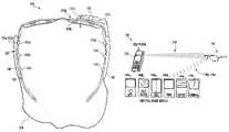
- FIG. 1a perspective view drawing of an example wearable device (or system) 100 in accordance with a preferred embodiment of the present invention is shown.
- the device 100may implement clip-on modules with an embedded human input/output (I/O) interface for use with eyeglasses.
- the device 100generally comprises a frame (or eyeglasses) 102 and an apparatus 103 .
- the apparatus 103generally comprises a housing (or unit) 105 , a housing (or unit) 107 , a harness (or cable) 109 and a housing (or unit) 110 .
- the eyeglasses 102may include a main body 111 , a pair of lens openings 112 a - 112 b for mounting lenses 104 a - 104 b , a nose piece 114 and two temples 116 a - 116 b .
- the lens openings 112 a - 112 bmay define an optical path for a user wearing the eyeglasses 102 .
- the lenses 104 a - 104 bmay be implemented as prescription lenses, non-prescription lenses, tinted lenses, safety lenses and/or the like. In other embodiments, the lenses 104 a - 104 b may be absent from the lens openings 112 a - 112 b.
- the housing 105may be implemented as an electronics housing.
- the housing 105generally contains and/or supports a circuit (or module) 106 , a speaker 120 , a microphone 122 , a haptic device 124 , a bone conduction device 126 and two accelerometers 128 a - 128 b .
- the housing 105may be removably secured to a temple (e.g., the temple 116 b ) of the eyeglasses 102 .
- the housing 107may be implemented as a battery housing.
- the housing 107may contain and/or support a cavity 129 (see FIG. 2 ) and one or more switches 123 a - 123 d .
- the cavity 129may be implemented as a battery cavity.
- One or more batteries 108may be removably or permanently disposed within the cavity 129 .
- the housing 107may be removably secured to a temple (e.g., the temple 116 a ) of the eyeglasses 102 .
- the harness 109may electrically connect and optionally electronically connect the circuitry of the housing 105 with the circuitry and battery 108 of the housing 107 .
- the harness 109generally attaches to a back end of the housing 107 and a back end of the housing 105 .
- the harness 109may have a sufficient length to permit the harness 109 to act as a retention chord for the eyeglasses 102 .
- Other lengths and/or routes between the housings 105 and 107may be implemented to meet the criteria of a particular application.
- the circuit 106may be referred to as an electronics/radio frequency (RF) circuit.
- the electronics/RF circuit 106may be operational to provide two-way radio communications with other devices external to and remote from the housing 105 and the device 100 .
- the electronics/RF circuit 106may receive a voice signal in a receive message from an external telephone (or other device) and provide commands back to the telephone (or other device) in a transmit message.
- the commands provided to the telephonemay be generated in a hands-free manner (e.g., without a user pressing a button with his or her hands).
- the communicationsmay be implemented per a wireless Bluetooth standard, a wireless Universal Serial Bus (USB) standard, a cellular telephone standard and/or a WiFi standard. Other standard and/or propriety protocols may be implemented to meet the criteria of a particular application.
- USBwireless Universal Serial Bus
- the one or more batteries 108may provide electrical power to the electronic, the opto-electronic components and, in particular, the electronics/RF circuit 106 and the housing 110 .
- the battery 108may be implemented as a rechargeable and/or replaceable battery. Other battery technologies may be implemented to meet the criteria of a particular application.
- the housing (or device) 110may be implemented as a display device.
- the display device 110may be pivotally or rigidly attached to the housing 105 at a forward end of the housing 105 .
- an active position(as shown in FIG. 1 ) and a standby position (as shown in FIG. 3 ) may be defined.
- an active output generated by the display device 110may be located before a lens opening (e.g., lens opening 112 b ) such that an image presented to the user is inside the optical path defined by the lense openings 112 a - 112 b .
- the imagemay be placed in a periphery of a vision of a user.
- the display device 110While in the standby position, the display device 110 may be located outside the optical path defined by the lens openings 112 a - 112 b . In embodiments where the display device 110 is rigidly attached to the housing 105 , the display device 110 may be in the active position. Other mounting arrangements may be implemented to meet the criteria of a particular application.
- a design of the display device 110may provide a short image distance yet retain an “infinite” focus.
- a lens/mirror system 131 a - 131 b(see FIG. 2 ) may be included in an optical path of the display device 110 to shorten the optical path.
- a display element 133 within the display device 110may be implemented as a liquid crystal display (LCD), organic LCD (OLCD), a light emitting diode (LED) or similar type of pixilated display.
- a passive ambient backlighting and/or an active backlighting schememay be included within the display device 110 to provide good visibility ranging from very bright ambient conditions to low light conditions. An example ambient backlighting scheme is generally described in co-pending U.S. patent application Ser. No. 11/233,163, filed Sep. 22, 2005 which is hereby incorporated by reference in its entirety.
- the speaker 120may be mounted on the housing 105 . Positioning of the speaker 120 may be such that a user wearing the device 100 may hear a sound generated by the speaker 120 .
- the microphone 122may be mounted on the housing 105 , preferably toward a front end near a lens opening 112 a and/or 112 b . The microphone may be operational to convert sounds received from the user into an electrical signal presented to the electronics/RF circuit 106 . Such responses may be generated in a hands-free manner.
- the speaker 120may be controlled by the electronics/RF circuit 106 .
- the electronics/RF circuit 106may send an electrical signal to the speaker 120 to create an audible sound.
- the audible soundmay be a voice from a telephone and/or a tone generated internal to the electronics/RF circuit 106 .
- the microphone 122may provide the user's voice to the electronics/RF circuit 106 .
- the electronics/RF circuit 106may process the voice data in different ways, depending on the application and/or current mode of operation. For example, when the microphone 122 is used for voice communications via a telephone, the electronics/RF circuit 106 may package and present the user voice data in a transmit message transmitted to an external telephone. In another example, the microphone 122 may be used to sample voice-based commands spoken by the user. As such, the electronics/RF circuit 106 may include a voice recognition capability (e.g., software and/or firmware). Based on the words detected, the electronics/RF circuit 106 may transmit one or more commands to external devices and/or change one or more settings in the device 100 (e.g., switch the artificial backlighting on/off in the display device 110 ).
- a voice recognition capabilitye.g., software and/or firmware
- the switches 123 a - 123 dmay be mounted to the housing 107 (as shown) or to the housing 105 .
- the switches 123 a - 123 dgenerally allow the user to control various functions and priorities of the device 100 .
- a first switche.g., 123 a
- Another switche.g., 123 b
- Another switche.g., 123 b
- Still another example switch 123e.g., 123 c
- Other user controlled featuresmay be implemented to meet the criteria of a particular application.
- the bone conduction device 124may be mounted in the housing 105 (as shown) and/or in the housing 107 .
- a shape and positioning of the bone conduction device 124may be adapted to make physical contact with a bone (e.g., a skull) of the user when wearing the device 100 .
- the bone conduction device 124may be operational to transfer vibrations to the user through the user's bones.
- the vibrationsmay be in the form of a voice (or speech) that may be sensed audibly to the user, an incoming phone call ring vibration, a notification vibration, a warning vibration or the like.
- the bone conduction device 124may also operate as a microphone to detect the user's voice.
- the detected voicemay be transferred to the electronics/RF circuit 106 for incorporation into a transmit message sent external to the device 100 .
- the bone conduction device 124When operating as a speaker, the bone conduction device 124 may be used in place of, or in addition to the speaker 120 .
- the bone conduction device 124When operating as a microphone, the bone conduction device 124 may be used in place of, or in addition to the microphone 122 .
- the haptic device 126may be mounted in the housing 105 (as shown) or in the housing 107 .
- the haptic device 126may be operational to generate vibrations that may be felt by the user.
- the vibrationsmay indicate, but are not limited to, an incoming phone call (e.g., a ring vibration), an alert vibration, a notification vibration or the like.
- the haptic device 126may be controlled by the electronics/RF circuit 106 .
- the accelerometers 128 a - 128 bmay be mounted in the housing 105 (as shown) and/or in the housing 107 .
- a first accelerometer 128 amay be oriented to sense a pitch movement of the eyeglasses 102 (e.g., a movement of the user's head) about a pitch (or horizontal) axis. The pitch axis may be defined from left to right through the eyeglasses 102 .
- a second accelerometer 128 bmay be oriented to sense a yaw movement of the eyeglasses 102 (e.g., a movement of the user's head) about a yaw (or vertical) axis.
- the yaw axismay be defined as a vertical (relative to the ground) axis through the eyeglasses 102 .
- the accelerometers 128 a - 128 bmay be used by the electronics/RF circuit 106 to receive inputs from the user. For example, to answer a telephone call, the electronics/RF circuit 106 may send the telephone a command to answer the call in response to the accelerometers 128 a - 128 b detecting a nodding “yes” (pitch) movement of the user's head. A shaking “no” (yaw) movement of the user's head may be cause the electronics/RF circuit 106 to generate a different command to the telephone not to answer the call.
- Each of the accelerometers 128 a - 128 bmay be operational to sense and report a direction of acceleration.
- the pitch accelerometer 128 amay generate a positive value in response to a forward rotation (e.g., user's nose moving down) of the eyeglasses 102 about the pitch axis.
- a negative valuemay be generated in response to a backwards rotation (e.g., user's nose moving upwards) of the eyeglasses 102 about the pitch axis.
- the yaw accelerometer 128 bmay generate a positive value for a clockwise rotation of the eyeglasses 102 (e.g., user's left ear forward, right ear backwards) about the yaw axis.
- a negative valuemay be generated for a counterclockwise rotation of the eyeglasses 102 (e.g., user's left ear backwards, right ear forward) about the yaw axis.
- the housing 107may include the cavity 129 .
- the cavity 129may hold the battery 108 .
- Multiple clips (or fasteners) 135 a - 135 fmay be formed and/or attached to an exterior of the housing 105 and an exterior of the housing 107 .
- the clips 135 a - 135 fmay be shaped to allow the housing 105 and the housing 107 to be removably secured to the temples 116 a - 116 b .
- a single clip (e.g., 135 b and 135 e ) on each of the housings 105 and 107may be sufficient to attach the housings 105 and 107 to the temples 116 a - 116 b .
- each housing 105 and 107may include multiple clips 135 a - 135 f for connecting to the temples 116 a - 116 b .
- the clips 135 a - 135 fmay be implemented to form a permanent attachment between the housings 105 and 107 and the temples 116 a - 116 b.
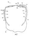
- FIG. 3a front view drawing of the device 100 is shown.
- the display device 110is generally illustrated in the standby position where the display device 110 has been rotation upward approximately 90 degrees. While in the standby position, the display device 110 may not obstruct any portion of the user's field of view. In some embodiments, other non-active position or positions may be defined to meet the criteria of a particular application.
- the system 140generally comprises the device 100 , a telephone 142 and possibly one or more external devices 144 a - 144 n .
- the external devices 144 a - 144 nmay include, but are not limited to a compass, a Global Positioning System (GPS) receiver, a gas detector (e.g., propane gas), a voltmeter, a PALM personal computer, a laptop computer, a speedometer, an odometer, an altimeter, a digital audio (e.g., MP3) player and the like.
- An RF communication link 146may be established between the telephone 142 and the device 100 .
- One or more RF communication links 148 a - 148 nmay be established between the device 100 and the respective external devices 144 a - 144 n.
- the communications link 146may be a two-way link. For example, voice data, caller identification, instant messaging and/or text messaging may be transferred from the telephone 142 to the device 100 via one or more messages in the communication link 146 . In turn, the device 100 may transmit voice data and commands (e.g., answer a call, end a call, etc.) via one or more messages transmitted in the communication link 146 to the telephone 142 .
- voice data and commandse.g., answer a call, end a call, etc.
- the other communication links 148 a - 148 nmay be any combination of one-way and/or two-way links.
- a voltmeter type of external devicee.g., 144 b
- the device 100may not return any data or commands to the voltmeter.
- a GPS type of external devicee.g., 144 a
- the device 100may transmit menu and cursor commands from the user back to the GPS device.
- the device 100may send messages (e.g., lights on/off) to one or more of the external devices 144 a - 144 n via other respective one-way communication links 148 a - 148 n.
- FIG. 5a diagram of a user 90 wearing the device 100 is shown.
- the user 90may speak creating sound waves 92 that are detectable by the microphone 122 .
- the microphone 122may convert the sound waves into an electrical signal presented to the electronics/RF circuit 106 .
- the electronics/RF circuit 106may format the electronic representations of the sound waves 92 and then transmit the data in a message via the communication link 146 to the telephone 142 .
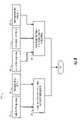
- the electronics/RF circuit 106generally comprises a processor (or microcontroller) 160 , a transceiver 162 , a memory circuit 164 , a temperature sensor 166 and a display driver 167 .
- the processor 160may include a real time clock 168 .
- An antenna 170may be embedded in the housing 105 external to the electronics/RF circuit 106 , formed as part of the harness 109 or the antenna 170 may be part of the electronics/RF circuit 106 .
- the display driver 167may be part of the processor 160 .
- a power signal(e.g., PWR) may be received by the electronics/RF circuit 106 from the battery 108 .
- a temperature signal(e.g., TMP) may be transferred from the temperature sensor 166 to the processor 160 .
- the processor 160may exchange data and instructions with the memory circuit 164 via a signal (e.g., MEM).
- a transmit/receive signal(e.g., TR) may exchange messages between the processor 160 and the transceiver 162 .
- the transceiver 162may exchange messages with the external devices 142 and/or 144 a - 144 n via a radio frequence signal (e.g., RF) on the antenna 170 .
- a real time clock signal(e.g., RTC) may be generated by the clock circuit 168 for use by the processor 160 .
- the display driver 167may send an image signal (e.g., IMAGE) to the display device 110 for displaying to the user.
- the processor 160may send a backlighting signal (e.g., BKL) to the display device 110 when ambient lighting conditions are low.
- An audio signal(e.g., AUDIO) may be sent from the processor 160 to the speaker 120 .
- a speech signal(e.g., MIC) may be received by the processor 160 from the microphone 122 .
- the processor 160may send a bone conduction output signal (e.g., BCO) to the bone conduction device 124 for transfer to the user.
- a bone conduction input signal(e.g., BCI) may be received by the processor 160 from the user via the bone conduction device 124 .
- a notification signal(e.g., NOTIFY) may be presented from the processor 160 to the haptic device 126 for transfer to the user.
- Two acceleration signals(e.g., ACP and ACY) may be sent from the respective accelerometers 128 a - 128 b to the processor 160 .
- the call processing method (or process) 180generally comprises a step (or block) 182 , a step (or block) 184 , a step (or block) 186 and a step (or block) 188 .
- the method 180generally starts in the step 182 with the electronics/RF circuit 106 receiving an incoming message indicating that a new telephone call has been received by the telephone 142 . If the incoming message includes a caller identification (ID), the electronics/RF circuit 106 may generate an alphanumeric image of the caller ID in the signal IMAGE for display to the user via the display device 110 in the step 184 .
- IDcaller identification
- the electronics/RF circuit 106may generate a ring tone in the signal AUDIO in the step 186 to get the user's attention. If the device 100 include the haptic device 126 and/or the bone conduction device 124 , the electronics/RF circuit 106 may generate a ring tone in the signal NOTIFY and/or BCO in the step 188 to alert the user to the incoming call.
- the steps 184 , 186 and/or 188may be performed substantially simultaneously (as shown) or in any appropriate sequence.
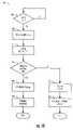
- the response method (or process) 200generally comprises a step (or block) 202 , a step (or block) 204 , a step (or block) 206 , a step (or block) 208 , a step (or block) 210 , a step (or block) 212 and a step (or block) 214 .
- the usermay decide to accept the call by nodding his head “yes” (e.g., pitch axis movement).
- the acceptancemay be detected by the pitch accelerometer 128 a generating the signal ACP in response to the movement.
- the processor 160may recognize the movement in the signal ACP within a finite window of time after receiving the incoming call message (e.g., the step 182 ).
- the processor 160may also detect that the user wants to accept the call in the step 204 by receiving an acceptance type speech (e.g., “Hello” in the signal MIC and/or the signal BCI).
- the processor 160may generate and format an acceptance message that is transmitted to the telephone 142 by the transceiver 162 in the step 206 .
- the usermay affirmatively reject the incoming call.
- the rejectionmay be indicated by shaking “no” with his head.
- the shakingmay be sensed by the yaw accelerometer 128 b and relayed to the processor 160 .
- the processor 160may conclude that the movement in the signal ACY may indicate that the incoming call has been rejected.
- the processor 160may also detect a rejection of the call by receiving a rejection type speech (e.g., “No” in the signal MIC and/or the signal BCI) from the user in the step 210 .
- a priority schememay be implemented to account for conflicting commands.
- the processor 160may detect the absence of an appreciable movement in the acceleration signals ACP and ACY and the lack of an appreciable sound in the signals MIC and BCI for a predetermined period after receiving the incoming call message.
- the processor 160may generate and format a rejection command in an outgoing message to the telephone in the step 214 .
- the conversation method (or process) 220generally comprises a step (or block) 222 , a step (or block) 224 , a step (or block) 226 , a step (or block) 228 , a step (or block) 230 and a step (or block) 232 .
- the transceiver 162may receive a voice signal from the telephone 142 in a receive message via the RF communication link 146 .
- the processor 160may translate the voice signal into an appropriate format and amplitude for the signal AUDIO and/or the signal BCO in the step 224 .
- the speaker 120 and/or the bone conduction device 124may transfer the telephone voice in the signals AUDIO and BCO respectively to the user in the step 226 .
- the microphone 122 and/or the bone conduction device 124may detect the user's voice and generate the respective signals MIC and BCI.
- the processor 160may transform the user's voice into an appropriate format for transmission to the telephone 142 in the step 230 .
- the transceiver 162may send the formatted voice of the user in a transmit message via the RF communication link 136 to the telephone 142 in the step 232 .
- the voice response method (or process) 240generally comprises a step (or block) 241 , a step (or block) 242 , a step (or block) 244 , a step (or block) 246 , a step (or block) 248 , a step (or block) 250 , a step (or block) 252 and a step (or block) 254 .
- the voice response method 240may be implemented in the electronics/RF circuit 106 .
- the processor 160may receive an audio signal (e.g., MIC or BCI) from the microphone 122 and/or the bone conduction device 124 . If an audio reception capability is enabled (e.g., the YES branch of step 241 ), the method 240 may proceed to the step 242 . If the audio reception capability is disabled (e.g., the NO branch of the step 241 ), the method 240 may ignore all audio signals received from the microphone 122 and/or the bone conduction device 124 .
- an audio reception capabilitye.g., MIC or BCI
- the processor 160may perform a voice recognition on the speech within the audio signal in the step 244 to determine a voice response/command. A decision may be made in the step 246 to determine if the recognized speech is destined for (i) transmission to one of the external devices 142 and/or 144 a - 144 n or (ii) a local component.
- the processor 160may generate an appropriate message in the step 248 .
- the transceiver 162may then transmit the message to the corresponding external device 142 or 144 a - 144 n in the step 250 .
- the processor 160may generate a command message intended for the telephone 142 to pick up the incoming call.
- the processor 160may adjust an appropriate signal to the targeted component in the step 252 .
- the targeted componentmay response to the signal in the step 254 .
- the processor 160may toggle the signal BKL to the display device 110 (e.g., on to off or off to on).
- a back lighting source in the display device 110may respond to the signal BLK by illuminating or extinguishing, as commanded.
- the movement response method (or process) 260generally comprises a step (or block 261 ), a step (or block) 262 , a step (or block) 263 , a step (or block) 264 , a step (or block) 266 , a step (or block) 268 , a step (or block) 270 , a step (or block) 272 , a step (or block) 274 and a step (or block) 276 .
- the movement response method 260may be implemented primarily in the electronics/RF circuit 106 .
- the method 260may continue with the step 262 . If the accelerometers 128 a - 128 b are off (e.g., the NO branch of step 261 ), the method 260 may exclude the signals ACP and ACY.
- the processor 160may receive the acceleration signals ACP and ACY from the accelerometers 128 a - 128 b .
- the processor 160may check for an overriding voice command. If a voice command has been received by the processor 160 and the voice command is different than the command sensed from the accelerometers 128 a - 128 b , the processor 160 may give precedence to the voice command and override the accelerometer command (e.g., the YES branch of step 263 ). If the voice command agrees with the accelerometer command or no voice command is received within a reasonable period around reception of the acceleration command, the processor 160 may continue to process the acceleration command (e.g., the NO branch of step 263 ).
- the amplitude of the accelerationsmay be checked in the step 264 against a minimal threshold to distinguish background movement from an intentional user command. If both accelerations are below the minimal threshold (e.g., the NO branch of step 264 ), the processor 160 may resample the signals ACP and ACY (e.g., step 252 ) at a later time. If one or both of the accelerations are above the minimal threshold (e.g., the YES branch of step 264 ), the processor 160 may monitor the acceleration signals ACP and ACY for a short period (e.g., 2 to 3 second) to determine the how the user is moving his head (e.g., up only, down only, nodding, left only, right only and/or shaking) in the step 266 .
- a short periode.g., 2 to 3 second
- the processor 160may check a current mode of operation and any recently received messages to determine if the command is intended as a response to an external stimuli or a command for an internal component in the step 268 . If the command is for an external device (e.g., the EXT branch of step 268 ), the processor 160 may generate and format a command message corresponding to the accelerations detected in the step 270 . The transceiver 162 may then transmit the command message to the appropriate external device in the step 272 . For example, an up only acceleration during a GPS mode may be interpreted as a command to move a cursor on a GPS type of external device (e.g., 144 a ) up a single position.
- an external devicee.g., the EXT branch of step 268
- a down only accelerationmay be interpreted as a command to move the cursor down.
- a left only motionmay be interpreted as a command to move up one level in the GPS menu and a right only command may result in a command to the GPS device to select the option currently pointed to by the cursor or vice-versa.
- the processor 160may adjust one or more corresponding internal signals in the step 274 based on the detected command.
- the components receiving the adjusted signalsmay respond according to the adjustments in the step 276 .
- a down only acceleration during a control modemay be interpreted as an instruction to change the current mode to a previous mode (e.g., a speedometer mode to a compass mode) and an up only acceleration may result in a change from the current mode to a next mode (e.g., the speedometer mode to a temperature mode) or vice-versa.
- the menu method (or process) 280generally comprises a step (or block) 282 , a step (or block) 284 , a step (or block) 286 , a step (or block) 288 , a step (or block) 290 , a step (or block) 292 , a step (or block) 294 , a step (or block) 296 , a step (or block) 298 , a step (or block) 300 and a step (or block) 302 .
- Examples of menu-driven type external devicesgenerally include, but are not limited to, the GPS receiver, the PALM personal computer, the laptop computer and the digital audio player.
- the processor 160may receive the acceleration signals ACP and ACY from the accelerometers 128 a - 128 b .
- the processor 160may check for a pitch motion in the step 284 . If movement down is detected (e.g., the DOWN branch of step 284 ), the processor 160 may generate a cursor down command in the step 286 .
- the transceiver 162may transmit the cursor down command to a particular external device 144 a - 144 n (e.g., the GPS device 144 a ).
- the external device 144 a - 144 nshould respond to the cursor down command by moving the cursor down a position in a current menu from a current cursor location.
- the processor 160may generate a cursor up command in the step 290 .
- the transceiver 162may transmit the cursor up command to the external device 144 a - 144 n .
- the external device 144 a - 144 nshould respond to the cursor up command by moving the cursor up a position in the current menu from the current cursor location.
- the processor 160may check for yaw movement in the step 294 . If movement left is detected (e.g., the LEFT branch of step 294 ), the processor 160 may generate an up-one-menu command in the step 296 . In the step 298 , the transceiver 162 may transmit the up-one-menu command to the external device 144 a - 144 n . The external device 144 a - 144 n should respond to the up-one-menu command by changing the current menu to a new menu higher in a menu structure.
- the processor 160may generate a select command in the step 300 .
- the in the step 302the transceiver 162 may transmit the select command to the external device 144 a - 144 n .
- the external device 144 a - 144 nshould respond to the select command by asserting a function at the current cursor location.
- the functionmay include, but is not limited to, moving down a level in the menu structure, activating a signal, deactivating a signal, toggling a mode or state, powering off and so on.
- the sensed movements in the various directionsmay be given different meanings.
- the up-one-menu commandmay be generated in response to a right movement while the select command may be generated in response to a left movement. If no yaw motion was detected or the yaw movement is in conflict with a voice command (e.g., the NONE) branch of step 294 ), the processor 160 may conclude that no input from the user is available at the present time. In some embodiments, the processor 160 may check for yaw motion first and then pitch motion.
- Housing 110 amay be similar to the housing 110 and optionally used in place of the housing 110 .
- the housing 110 agenerally comprises a first portion (or unit) 320 and a second portion (or unit) 322 .
- the portion 322may be pivotally attached to the housing 105 about an axis 324 (e.g., a roll axis).
- the portion 320may be slidably coupled to the portion 322 along a joint 326 .
- the joint 326generally allows the portion 320 to move linearly with respect to the portion 322 towards and away from the axis 324 , as indicated by arrow 328 .
- the movement 328generally allows the user to position of the image generated by the display element 133 horizontally along the top of the lens (e.g., 104 b ) at a desired location within the field of view.
- a control 330may be included to lock/release the portions 320 relative to the portion 322 .
- the usermay press the control 330 to release the portion 320 , move the portion 320 to an intended position, then release the control 330 to lock the portion 320 in place.
- Vertical movement of the image within the field of viewmay be achieved by rotating the housing 110 / 110 a about the axis 324 .
- One or more mirrorswithin the housing 110 a and/or the portion 320 may be adjustable to move a projected direction 332 of the image about the yaw axis (as indicated by the arrow 334 ) and/or the pitch axis (as indicated by the arrow 336 .)
- User adjustment of the mirrors/portionmay be achieved through a control 338 (e.g., yaw) and a control 340 (e.g., pitch).
- the pitch movement and the yaw movementgenerally enable the user to direct the projected direction 332 of the image directly toward (e.g., on axis) or near (e.g., off axis) the user's eye.
- a brightness of the imagemay be maximized where the image is angled straight toward the user's eye. Directing the image off-axis may cause the image to appear dimmer to the user.
- FIGS. 4-12may be implemented using a conventional general purpose digital computer programmed according to the teachings of the present specification, as will be apparent to those skilled in the relevant art(s).
- Appropriate software codingcan readily be prepared by skilled programmers based on the teachings of the present disclosure, as will also be apparent to those skilled in the relevant art(s).
- the present inventionmay also be implemented by the preparation of ASICs, FPGAs, or by interconnecting an appropriate network of conventional component circuits, as is described herein, modifications of which will be readily apparent to those skilled in the art(s).
- the present inventionthus may also include a computer product which may be a storage medium including instructions which can be used to program a computer to perform a process in accordance with the present invention.
- the storage mediumcan include, but is not limited to, any type of disk including floppy disk, optical disk, CD-ROM, magneto-optical disks, ROMS, RAMs, EPROMs, EEPROMs, Flash memory, magnetic or optical cards, or any type of media suitable for storing electronic instructions.
Landscapes
- Physics & Mathematics (AREA)
- Health & Medical Sciences (AREA)
- Otolaryngology (AREA)
- Acoustics & Sound (AREA)
- General Health & Medical Sciences (AREA)
- General Physics & Mathematics (AREA)
- Ophthalmology & Optometry (AREA)
- Optics & Photonics (AREA)
- Engineering & Computer Science (AREA)
- Signal Processing (AREA)
- Telephone Function (AREA)
Abstract
Description
Claims (22)
Priority Applications (1)
| Application Number | Priority Date | Filing Date | Title |
|---|---|---|---|
| US11/555,317US7631968B1 (en) | 2006-11-01 | 2006-11-01 | Cell phone display that clips onto eyeglasses |
Applications Claiming Priority (1)
| Application Number | Priority Date | Filing Date | Title |
|---|---|---|---|
| US11/555,317US7631968B1 (en) | 2006-11-01 | 2006-11-01 | Cell phone display that clips onto eyeglasses |
Publications (1)
| Publication Number | Publication Date |
|---|---|
| US7631968B1true US7631968B1 (en) | 2009-12-15 |
Family
ID=41403192
Family Applications (1)
| Application Number | Title | Priority Date | Filing Date |
|---|---|---|---|
| US11/555,317Active2027-06-17US7631968B1 (en) | 2006-11-01 | 2006-11-01 | Cell phone display that clips onto eyeglasses |
Country Status (1)
| Country | Link |
|---|---|
| US (1) | US7631968B1 (en) |
Cited By (119)
| Publication number | Priority date | Publication date | Assignee | Title |
|---|---|---|---|---|
| US20080084362A1 (en)* | 2002-08-12 | 2008-04-10 | Scalar Corporation | Image display device |
| US20080268920A1 (en)* | 2007-04-23 | 2008-10-30 | Patent Navigation Inc. | Turbulence sensitive mobile device power control |
| US20100245757A1 (en)* | 2009-03-25 | 2010-09-30 | Olympus Corporation | Eyeglass-mounted type image display device |
| US20100253904A1 (en)* | 2006-12-14 | 2010-10-07 | James Jannard | Wearable high resolution audio visual interface |
| US20100271587A1 (en)* | 2007-06-07 | 2010-10-28 | Panagiotis Pavlopoulos | eyewear comprising at least one display device |
| WO2012034291A1 (en)* | 2010-09-17 | 2012-03-22 | Joker Manufacturing &Technologies (Shenzhen) Co., Ltd | Spectacles |
| USD659137S1 (en)* | 2009-10-19 | 2012-05-08 | Brother Industries, Ltd. | Image display device |
| USD659136S1 (en)* | 2009-10-19 | 2012-05-08 | Brother Industries, Ltd. | Image display device |
| US20120133910A1 (en)* | 2010-11-26 | 2012-05-31 | Welmore Co., Ltd. | Optical digital display apparatus |
| US20120206323A1 (en)* | 2010-02-28 | 2012-08-16 | Osterhout Group, Inc. | Ar glasses with event and sensor triggered ar eyepiece interface to external devices |
| US20120212414A1 (en)* | 2010-02-28 | 2012-08-23 | Osterhout Group, Inc. | Ar glasses with event and sensor triggered control of ar eyepiece applications |
| USD666237S1 (en) | 2011-10-24 | 2012-08-28 | Google Inc. | Wearable display device |
| USD671589S1 (en) | 2011-10-24 | 2012-11-27 | Google Inc. | Wearable display device |
| WO2012161639A1 (en)* | 2011-05-25 | 2012-11-29 | Is International | Exercise glasses |
| WO2013019893A1 (en) | 2011-08-02 | 2013-02-07 | Oakley, Inc. | Eyewear with detachable adjustable electronics module |
| US20130088413A1 (en)* | 2011-10-05 | 2013-04-11 | Google Inc. | Method to Autofocus on Near-Eye Display |
| CN103095927A (en)* | 2013-02-06 | 2013-05-08 | 吴玉胜 | Displaying and voice outputting method and system based on mobile communication terminal and glasses |
| US20130141313A1 (en)* | 2011-07-18 | 2013-06-06 | Tiger T.G. Zhou | Wearable personal digital eyeglass device |
| US8467133B2 (en) | 2010-02-28 | 2013-06-18 | Osterhout Group, Inc. | See-through display with an optical assembly including a wedge-shaped illumination system |
| US8472120B2 (en) | 2010-02-28 | 2013-06-25 | Osterhout Group, Inc. | See-through near-eye display glasses with a small scale image source |
| US8477425B2 (en) | 2010-02-28 | 2013-07-02 | Osterhout Group, Inc. | See-through near-eye display glasses including a partially reflective, partially transmitting optical element |
| US8482859B2 (en) | 2010-02-28 | 2013-07-09 | Osterhout Group, Inc. | See-through near-eye display glasses wherein image light is transmitted to and reflected from an optically flat film |
| WO2013103825A1 (en) | 2012-01-05 | 2013-07-11 | Google Inc. | Wearable device assembly with input and output structures |
| US8488246B2 (en) | 2010-02-28 | 2013-07-16 | Osterhout Group, Inc. | See-through near-eye display glasses including a curved polarizing film in the image source, a partially reflective, partially transmitting optical element and an optically flat film |
| US8523352B2 (en) | 2000-06-02 | 2013-09-03 | Oakley, Inc. | Media communication device |
| US20130329183A1 (en)* | 2012-06-11 | 2013-12-12 | Pixeloptics, Inc. | Adapter For Eyewear |
| US20130346168A1 (en)* | 2011-07-18 | 2013-12-26 | Dylan T X Zhou | Wearable augmented reality eyeglass communication device including mobile phone and mobile computing via virtual touch screen gesture control and neuron command |
| US20140064536A1 (en)* | 2012-08-28 | 2014-03-06 | Google Inc. | Thin Film Bone-Conduction Transducer for a Wearable Computing System |
| JP2014071757A (en)* | 2012-09-28 | 2014-04-21 | Brother Ind Ltd | Work assistance system and program |
| USD703724S1 (en) | 2011-10-24 | 2014-04-29 | Google Inc. | Wearable display device |
| USD703726S1 (en) | 2011-10-24 | 2014-04-29 | Google Inc. | Wearable display device |
| USD704247S1 (en) | 2011-10-24 | 2014-05-06 | Google Inc. | Display device component |
| WO2014074858A1 (en)* | 2012-11-09 | 2014-05-15 | The Arizona Board Of Regents On Behalf Of The University Of Arizona | Glass implemented display |
| USD708181S1 (en) | 2012-03-22 | 2014-07-01 | Google Inc. | Wearable display device |
| US8787970B2 (en) | 2001-06-21 | 2014-07-22 | Oakley, Inc. | Eyeglasses with electronic components |
| USD710928S1 (en) | 2012-09-25 | 2014-08-12 | Google Inc. | Wearable display device |
| US8814691B2 (en) | 2010-02-28 | 2014-08-26 | Microsoft Corporation | System and method for social networking gaming with an augmented reality |
| US8818464B2 (en) | 2012-03-21 | 2014-08-26 | Google Inc. | Device case with added functionality |
| USD712451S1 (en) | 2012-09-25 | 2014-09-02 | Google Inc. | Removably attachable lens |
| US20140317200A1 (en)* | 2013-04-17 | 2014-10-23 | Nokia Corporation | Method and Apparatus for a Textural Representation of a Notification |
| USD716299S1 (en) | 2012-03-22 | 2014-10-28 | Google Inc. | Wearable display device |
| USD716806S1 (en) | 2012-03-22 | 2014-11-04 | Google Inc. | Wearable display device |
| USD716805S1 (en) | 2012-03-22 | 2014-11-04 | Google Inc. | Wearable display device and connection cable combination |
| WO2014184700A1 (en) | 2013-05-13 | 2014-11-20 | Koninklijke Philips N.V. | Device with a graphical user interface for controlling lighting properties |
| USD718305S1 (en) | 2012-03-22 | 2014-11-25 | Google Inc. | Wearable display device |
| CN104216139A (en)* | 2013-05-30 | 2014-12-17 | 许振宇 | Clamping piece for connecting traditional glasses and multimedia accessories |
| USD721758S1 (en) | 2013-02-19 | 2015-01-27 | Google Inc. | Removably attachable lens |
| US8971023B2 (en) | 2012-03-21 | 2015-03-03 | Google Inc. | Wearable computing device frame |
| US8968012B2 (en) | 2012-03-22 | 2015-03-03 | Google Inc. | Device connection cable |
| WO2015031240A1 (en)* | 2013-08-27 | 2015-03-05 | Johnson & Johnson Vision Care, Inc. | Ophthalmic lens with micro-acoustic elements |
| US8976085B2 (en) | 2012-01-19 | 2015-03-10 | Google Inc. | Wearable device with input and output structures |
| WO2015032014A1 (en)* | 2013-09-03 | 2015-03-12 | 常州菲胜图自动化仪器有限公司 | Intelligent glasses and method for monitoring movement, preventing myopia and correcting sitting posture using same |
| TWI486666B (en)* | 2013-05-23 | 2015-06-01 | Omnivision Tech Inc | Mounting system for glasses frames |
| USD731483S1 (en) | 2012-03-22 | 2015-06-09 | Google Inc. | Combined display device and case |
| US20150189072A1 (en)* | 2013-12-27 | 2015-07-02 | Saurin Shah | Intelligent ancillary electronic device |
| US9075249B2 (en) | 2012-03-07 | 2015-07-07 | Google Inc. | Eyeglass frame with input and output functionality |
| US9091850B2 (en) | 2011-07-20 | 2015-07-28 | Google Inc. | Compact see-through display system |
| US9091851B2 (en) | 2010-02-28 | 2015-07-28 | Microsoft Technology Licensing, Llc | Light control in head mounted displays |
| US9091852B2 (en) | 2012-03-21 | 2015-07-28 | Google Inc. | Wearable device with input and output structures |
| US9097890B2 (en) | 2010-02-28 | 2015-08-04 | Microsoft Technology Licensing, Llc | Grating in a light transmissive illumination system for see-through near-eye display glasses |
| US9097891B2 (en) | 2010-02-28 | 2015-08-04 | Microsoft Technology Licensing, Llc | See-through near-eye display glasses including an auto-brightness control for the display brightness based on the brightness in the environment |
| CN104871069A (en)* | 2012-12-13 | 2015-08-26 | 三星电子株式会社 | Glasses apparatus and method for controlling glasses apparatus, audio apparatus and method for providing audio signal and display apparatus |
| US9128281B2 (en) | 2010-09-14 | 2015-09-08 | Microsoft Technology Licensing, Llc | Eyepiece with uniformly illuminated reflective display |
| US9128284B2 (en) | 2013-02-18 | 2015-09-08 | Google Inc. | Device mountable lens component |
| US9129295B2 (en) | 2010-02-28 | 2015-09-08 | Microsoft Technology Licensing, Llc | See-through near-eye display glasses with a fast response photochromic film system for quick transition from dark to clear |
| JP2015526750A (en)* | 2012-06-12 | 2015-09-10 | レコン インストルメンツ インコーポレイテッドRecon Instruments Inc. | Head-up display system for glasses |
| US9134534B2 (en) | 2010-02-28 | 2015-09-15 | Microsoft Technology Licensing, Llc | See-through near-eye display glasses including a modular image source |
| US9134548B1 (en) | 2012-09-28 | 2015-09-15 | Google Inc. | Retention member for a lens system |
| CN104914578A (en)* | 2014-03-14 | 2015-09-16 | Lg电子株式会社 | Clip type display module and glass type terminal having the same |
| US9164284B2 (en) | 2011-08-18 | 2015-10-20 | Google Inc. | Wearable device with input and output structures |
| EP2932330A1 (en)* | 2012-12-13 | 2015-10-21 | Kopin Corporation | Spectacle with invisible optics |
| US9182596B2 (en) | 2010-02-28 | 2015-11-10 | Microsoft Technology Licensing, Llc | See-through near-eye display glasses with the optical assembly including absorptive polarizers or anti-reflective coatings to reduce stray light |
| USD745007S1 (en) | 2014-06-24 | 2015-12-08 | Google Inc. | Wearable hinged display device |
| US9223134B2 (en) | 2010-02-28 | 2015-12-29 | Microsoft Technology Licensing, Llc | Optical imperfections in a light transmissive illumination system for see-through near-eye display glasses |
| USD746817S1 (en) | 2014-01-28 | 2016-01-05 | Google Inc. | Glasses frame |
| US9229227B2 (en) | 2010-02-28 | 2016-01-05 | Microsoft Technology Licensing, Llc | See-through near-eye display glasses with a light transmissive wedge shaped illumination system |
| USD747315S1 (en) | 2014-01-28 | 2016-01-12 | Google Inc. | Glasses frame |
| USD749074S1 (en) | 2014-06-24 | 2016-02-09 | Google Inc. | Wearable hinged display device |
| US9277334B1 (en) | 2012-03-21 | 2016-03-01 | Google Inc. | Wearable computing device authentication using bone conduction |
| US9291823B2 (en) | 2012-03-30 | 2016-03-22 | Google Inc. | Wearable device with input and output structures |
| US9323983B2 (en) | 2014-05-29 | 2016-04-26 | Comcast Cable Communications, Llc | Real-time image and audio replacement for visual acquisition devices |
| US9341843B2 (en) | 2010-02-28 | 2016-05-17 | Microsoft Technology Licensing, Llc | See-through near-eye display glasses with a small scale image source |
| US9366862B2 (en) | 2010-02-28 | 2016-06-14 | Microsoft Technology Licensing, Llc | System and method for delivering content to a group of see-through near eye display eyepieces |
| RU2593391C2 (en)* | 2013-07-11 | 2016-08-10 | Джонсон Энд Джонсон Вижн Кэа, Инк. | Methods for application and implementation of event notification by smartphone by wearing energised ophthalmic lens with mechanism for displaying events of smartphone |
| JP2016149781A (en)* | 2016-03-15 | 2016-08-18 | 株式会社ファインウェル | Hearing unit |
| EP2954367A4 (en)* | 2013-02-07 | 2016-09-14 | Google Inc | Modular frame construction for head mountable display |
| US20160274357A1 (en)* | 2013-11-12 | 2016-09-22 | Lg Electronics Inc. | Glass type terminal |
| US9477095B1 (en)* | 2015-06-26 | 2016-10-25 | Charmant Co., Ltd. | Eyeglasses |
| USD769873S1 (en) | 2014-06-27 | 2016-10-25 | Google Inc. | Interchangeable/wearable hinged display device assembly |
| US20160327799A1 (en)* | 2008-09-30 | 2016-11-10 | Apple Inc. | Head-Mounted Display Apparatus for Retaining a Portable Electronic Device with Display |
| RU2607640C2 (en)* | 2013-07-11 | 2017-01-10 | Джонсон Энд Джонсон Вижн Кэа, Инк. | Powered ophthalmic lens with smartphone events sensor |
| USD776751S1 (en) | 2014-06-27 | 2017-01-17 | Google Inc. | Interchangeable eyewear assembly |
| US9579060B1 (en) | 2014-02-18 | 2017-02-28 | Orbitol Research Inc. | Head-mounted physiological signal monitoring system, devices and methods |
| US9599824B2 (en) | 2014-02-18 | 2017-03-21 | Merge Labs, Inc. | Soft head mounted display goggles for use with mobile computing devices |
| US9606358B1 (en) | 2012-02-16 | 2017-03-28 | Google Inc. | Wearable device with input and output structures |
| US9720260B2 (en) | 2013-06-12 | 2017-08-01 | Oakley, Inc. | Modular heads-up display system |
| US9720258B2 (en) | 2013-03-15 | 2017-08-01 | Oakley, Inc. | Electronic ornamentation for eyewear |
| US9767160B2 (en) | 2012-10-19 | 2017-09-19 | Patent Analytics Holding Pty Ltd | System and method for presentation and visual navigation of network data sets |
| US9801560B2 (en) | 2013-08-27 | 2017-10-31 | Johnson & Johnson Vision Care, Inc. | Ophthalmic lens with a neural frequency detection system |
| US9851575B2 (en) | 2014-05-15 | 2017-12-26 | Omnivision Technologies, Inc. | Wafer-level liquid-crystal-on-silicon projection assembly, systems and methods |
| US9851567B2 (en) | 2014-08-13 | 2017-12-26 | Google Llc | Interchangeable eyewear/head-mounted device assembly with quick release mechanism |
| US9927619B2 (en) | 2015-11-06 | 2018-03-27 | Omnivision Technologies, Inc. | Pupillary adjustable head mounted device |
| US10027606B2 (en) | 2013-04-17 | 2018-07-17 | Nokia Technologies Oy | Method and apparatus for determining a notification representation indicative of a cognitive load |
| US10168766B2 (en) | 2013-04-17 | 2019-01-01 | Nokia Technologies Oy | Method and apparatus for a textural representation of a guidance |
| US10180572B2 (en) | 2010-02-28 | 2019-01-15 | Microsoft Technology Licensing, Llc | AR glasses with event and user action control of external applications |
| US10222617B2 (en) | 2004-12-22 | 2019-03-05 | Oakley, Inc. | Wearable electronically enabled interface system |
| EP3499300A4 (en)* | 2017-10-19 | 2019-06-19 | Goertek Technology Co., Ltd. | GLASSES WITH INCREASED REALITY |
| US10359835B2 (en) | 2013-04-17 | 2019-07-23 | Nokia Technologies Oy | Method and apparatus for causing display of notification content |
| US10373524B2 (en)* | 2009-07-10 | 2019-08-06 | Lincoln Global, Inc. | Systems and methods providing a computerized eyewear device to aid in welding |
| WO2019178557A1 (en)* | 2018-03-15 | 2019-09-19 | Vizzario, Inc. | Modular display and sensor system for attaching to eyeglass frames and capturing physiological data |
| US10539787B2 (en) | 2010-02-28 | 2020-01-21 | Microsoft Technology Licensing, Llc | Head-worn adaptive display |
| US10628104B2 (en)* | 2017-12-27 | 2020-04-21 | Toshiba Client Solutions CO., LTD. | Electronic device, wearable device, and display control method |
| US10690918B2 (en) | 2016-12-19 | 2020-06-23 | United States Of America As Represented By The Administrator Of Nasa | Optical head-mounted displays for laser safety eyewear |
| US10809536B2 (en) | 2017-10-19 | 2020-10-20 | Goertek Technology Co., Ltd. | Augmented reality glasses |
| US10860100B2 (en) | 2010-02-28 | 2020-12-08 | Microsoft Technology Licensing, Llc | AR glasses with predictive control of external device based on event input |
| US10925772B2 (en) | 2013-03-07 | 2021-02-23 | Oakley, Inc. | Regeneratable anti-fogging element for goggle |
| CN115066599A (en)* | 2020-02-03 | 2022-09-16 | 日本电信电话株式会社 | Wearable equipment and body temperature reminder system |
| US11487138B2 (en)* | 2012-01-06 | 2022-11-01 | E-Vision Smart Optics, Inc. | Eyewear docking station and electronic module |
| US11934038B1 (en)* | 2019-08-15 | 2024-03-19 | Snap Inc. | Eyewear tether |
Citations (9)
| Publication number | Priority date | Publication date | Assignee | Title |
|---|---|---|---|---|
| US5162828A (en) | 1986-09-25 | 1992-11-10 | Furness Thomas A | Display system for a head mounted viewing transparency |
| US6034653A (en)* | 1997-08-01 | 2000-03-07 | Colorado Microdisplay, Inc. | Head-set display device |
| US6091832A (en) | 1996-08-12 | 2000-07-18 | Interval Research Corporation | Wearable personal audio loop apparatus |
| US6160666A (en) | 1994-02-07 | 2000-12-12 | I-O Display Systems Llc | Personal visual display system |
| US6349001B1 (en) | 1997-10-30 | 2002-02-19 | The Microoptical Corporation | Eyeglass interface system |
| US6769767B2 (en) | 2001-04-30 | 2004-08-03 | Qr Spex, Inc. | Eyewear with exchangeable temples housing a transceiver forming ad hoc networks with other devices |
| US20060119540A1 (en) | 2004-09-22 | 2006-06-08 | Dominic Dobson | Ambient light display and system for displaying data |
| US20060250574A1 (en) | 2005-05-03 | 2006-11-09 | Grand Joseph B | Method and apparatus for displaying images on reflective surfaces |
| US7158096B1 (en)* | 1999-06-21 | 2007-01-02 | The Microoptical Corporation | Compact, head-mountable display device with suspended eyepiece assembly |
- 2006
- 2006-11-01USUS11/555,317patent/US7631968B1/enactiveActive
Patent Citations (9)
| Publication number | Priority date | Publication date | Assignee | Title |
|---|---|---|---|---|
| US5162828A (en) | 1986-09-25 | 1992-11-10 | Furness Thomas A | Display system for a head mounted viewing transparency |
| US6160666A (en) | 1994-02-07 | 2000-12-12 | I-O Display Systems Llc | Personal visual display system |
| US6091832A (en) | 1996-08-12 | 2000-07-18 | Interval Research Corporation | Wearable personal audio loop apparatus |
| US6034653A (en)* | 1997-08-01 | 2000-03-07 | Colorado Microdisplay, Inc. | Head-set display device |
| US6349001B1 (en) | 1997-10-30 | 2002-02-19 | The Microoptical Corporation | Eyeglass interface system |
| US7158096B1 (en)* | 1999-06-21 | 2007-01-02 | The Microoptical Corporation | Compact, head-mountable display device with suspended eyepiece assembly |
| US6769767B2 (en) | 2001-04-30 | 2004-08-03 | Qr Spex, Inc. | Eyewear with exchangeable temples housing a transceiver forming ad hoc networks with other devices |
| US20060119540A1 (en) | 2004-09-22 | 2006-06-08 | Dominic Dobson | Ambient light display and system for displaying data |
| US20060250574A1 (en) | 2005-05-03 | 2006-11-09 | Grand Joseph B | Method and apparatus for displaying images on reflective surfaces |
Cited By (232)
| Publication number | Priority date | Publication date | Assignee | Title |
|---|---|---|---|---|
| US8523352B2 (en) | 2000-06-02 | 2013-09-03 | Oakley, Inc. | Media communication device |
| US9619201B2 (en) | 2000-06-02 | 2017-04-11 | Oakley, Inc. | Eyewear with detachable adjustable electronics module |
| US9451068B2 (en) | 2001-06-21 | 2016-09-20 | Oakley, Inc. | Eyeglasses with electronic components |
| US8787970B2 (en) | 2001-06-21 | 2014-07-22 | Oakley, Inc. | Eyeglasses with electronic components |
| US20080084362A1 (en)* | 2002-08-12 | 2008-04-10 | Scalar Corporation | Image display device |
| US7982689B2 (en)* | 2002-08-12 | 2011-07-19 | Scalar Corporation | Image display device |
| US10222617B2 (en) | 2004-12-22 | 2019-03-05 | Oakley, Inc. | Wearable electronically enabled interface system |
| US10120646B2 (en) | 2005-02-11 | 2018-11-06 | Oakley, Inc. | Eyewear with detachable adjustable electronics module |
| US9720240B2 (en) | 2006-12-14 | 2017-08-01 | Oakley, Inc. | Wearable high resolution audio visual interface |
| US8025398B2 (en)* | 2006-12-14 | 2011-09-27 | Oakley, Inc. | Wearable high resolution audio visual interface |
| US20100253904A1 (en)* | 2006-12-14 | 2010-10-07 | James Jannard | Wearable high resolution audio visual interface |
| US8550621B2 (en) | 2006-12-14 | 2013-10-08 | Oakley, Inc. | Wearable high resolution audio visual interface |
| US8876285B2 (en) | 2006-12-14 | 2014-11-04 | Oakley, Inc. | Wearable high resolution audio visual interface |
| US8313192B2 (en) | 2006-12-14 | 2012-11-20 | Oakley, Inc. | Wearable high resolution audio visual interface |
| US10288886B2 (en) | 2006-12-14 | 2019-05-14 | Oakley, Inc. | Wearable high resolution audio visual interface |
| US9494807B2 (en) | 2006-12-14 | 2016-11-15 | Oakley, Inc. | Wearable high resolution audio visual interface |
| US20080268920A1 (en)* | 2007-04-23 | 2008-10-30 | Patent Navigation Inc. | Turbulence sensitive mobile device power control |
| US20100271587A1 (en)* | 2007-06-07 | 2010-10-28 | Panagiotis Pavlopoulos | eyewear comprising at least one display device |
| US10306038B2 (en) | 2008-09-30 | 2019-05-28 | Apple Inc. | Head-mounted display apparatus for retaining a portable electronic device with display |
| US10897528B2 (en) | 2008-09-30 | 2021-01-19 | Apple Inc. | Head-mounted display apparatus for retaining a portable electronic device with display |
| US10530915B2 (en) | 2008-09-30 | 2020-01-07 | Apple Inc. | Head-mounted display apparatus for retaining a portable electronic device with display |
| US9749451B2 (en) | 2008-09-30 | 2017-08-29 | Apple Inc. | Head-mounted display apparatus for retaining a portable electronic device with display |
| US11258891B2 (en) | 2008-09-30 | 2022-02-22 | Apple Inc. | Head-mounted display apparatus for retaining a portable electronic device with display |
| US20160327799A1 (en)* | 2008-09-30 | 2016-11-10 | Apple Inc. | Head-Mounted Display Apparatus for Retaining a Portable Electronic Device with Display |
| US10530914B2 (en) | 2008-09-30 | 2020-01-07 | Apple Inc. | Head-mounted display apparatus for retaining a portable electronic device with display |
| US20170011716A1 (en)* | 2008-09-30 | 2017-01-12 | Apple Inc. | Head-Mounted Display Apparatus for Retaining a Portable Electronic Device with Display |
| US10306037B2 (en) | 2008-09-30 | 2019-05-28 | Apple Inc. | Head-mounted display apparatus for retaining a portable electronic device with display |
| US9595237B2 (en)* | 2008-09-30 | 2017-03-14 | Apple Inc. | Head-mounted display apparatus for retaining a portable electronic device with display |
| US10686922B2 (en) | 2008-09-30 | 2020-06-16 | Apple Inc. | Head-mounted display apparatus for retaining a portable electronic device with display |
| US11716412B2 (en) | 2008-09-30 | 2023-08-01 | Apple Inc. | Head-mounted display apparatus for retaining a portable electronic device with display |
| US9646574B2 (en)* | 2008-09-30 | 2017-05-09 | Apple Inc. | Head-mounted display apparatus for retaining a portable electronic device with display |
| US12126748B2 (en) | 2008-09-30 | 2024-10-22 | Apple Inc. | Head-mounted display apparatus for retaining a portable electronic device with display |
| US11089144B2 (en) | 2008-09-30 | 2021-08-10 | Apple Inc. | Head-mounted display apparatus for retaining a portable electronic device with display |
| US10306036B2 (en) | 2008-09-30 | 2019-05-28 | Apple Inc. | Head-mounted display apparatus for retaining a portable electronic device with display |
| US9646573B2 (en) | 2008-09-30 | 2017-05-09 | Apple Inc. | Head-mounted display apparatus for retaining a portable electronic device with display |
| US20100245757A1 (en)* | 2009-03-25 | 2010-09-30 | Olympus Corporation | Eyeglass-mounted type image display device |
| US10991267B2 (en) | 2009-07-10 | 2021-04-27 | Lincoln Global, Inc. | Systems and methods providing a computerized eyewear device to aid in welding |
| US10373524B2 (en)* | 2009-07-10 | 2019-08-06 | Lincoln Global, Inc. | Systems and methods providing a computerized eyewear device to aid in welding |
| USD659136S1 (en)* | 2009-10-19 | 2012-05-08 | Brother Industries, Ltd. | Image display device |
| USD659137S1 (en)* | 2009-10-19 | 2012-05-08 | Brother Industries, Ltd. | Image display device |
| US8477425B2 (en) | 2010-02-28 | 2013-07-02 | Osterhout Group, Inc. | See-through near-eye display glasses including a partially reflective, partially transmitting optical element |
| US20120212414A1 (en)* | 2010-02-28 | 2012-08-23 | Osterhout Group, Inc. | Ar glasses with event and sensor triggered control of ar eyepiece applications |
| US9134534B2 (en) | 2010-02-28 | 2015-09-15 | Microsoft Technology Licensing, Llc | See-through near-eye display glasses including a modular image source |
| US10180572B2 (en) | 2010-02-28 | 2019-01-15 | Microsoft Technology Licensing, Llc | AR glasses with event and user action control of external applications |
| US8814691B2 (en) | 2010-02-28 | 2014-08-26 | Microsoft Corporation | System and method for social networking gaming with an augmented reality |
| US9223134B2 (en) | 2010-02-28 | 2015-12-29 | Microsoft Technology Licensing, Llc | Optical imperfections in a light transmissive illumination system for see-through near-eye display glasses |
| US9129295B2 (en) | 2010-02-28 | 2015-09-08 | Microsoft Technology Licensing, Llc | See-through near-eye display glasses with a fast response photochromic film system for quick transition from dark to clear |
| US9875406B2 (en) | 2010-02-28 | 2018-01-23 | Microsoft Technology Licensing, Llc | Adjustable extension for temple arm |
| US9229227B2 (en) | 2010-02-28 | 2016-01-05 | Microsoft Technology Licensing, Llc | See-through near-eye display glasses with a light transmissive wedge shaped illumination system |
| US20120206323A1 (en)* | 2010-02-28 | 2012-08-16 | Osterhout Group, Inc. | Ar glasses with event and sensor triggered ar eyepiece interface to external devices |
| US9097891B2 (en) | 2010-02-28 | 2015-08-04 | Microsoft Technology Licensing, Llc | See-through near-eye display glasses including an auto-brightness control for the display brightness based on the brightness in the environment |
| US9097890B2 (en) | 2010-02-28 | 2015-08-04 | Microsoft Technology Licensing, Llc | Grating in a light transmissive illumination system for see-through near-eye display glasses |
| US9759917B2 (en)* | 2010-02-28 | 2017-09-12 | Microsoft Technology Licensing, Llc | AR glasses with event and sensor triggered AR eyepiece interface to external devices |
| US9091851B2 (en) | 2010-02-28 | 2015-07-28 | Microsoft Technology Licensing, Llc | Light control in head mounted displays |
| US10268888B2 (en) | 2010-02-28 | 2019-04-23 | Microsoft Technology Licensing, Llc | Method and apparatus for biometric data capture |
| US8488246B2 (en) | 2010-02-28 | 2013-07-16 | Osterhout Group, Inc. | See-through near-eye display glasses including a curved polarizing film in the image source, a partially reflective, partially transmitting optical element and an optically flat film |
| US10860100B2 (en) | 2010-02-28 | 2020-12-08 | Microsoft Technology Licensing, Llc | AR glasses with predictive control of external device based on event input |
| US9285589B2 (en)* | 2010-02-28 | 2016-03-15 | Microsoft Technology Licensing, Llc | AR glasses with event and sensor triggered control of AR eyepiece applications |
| US8482859B2 (en) | 2010-02-28 | 2013-07-09 | Osterhout Group, Inc. | See-through near-eye display glasses wherein image light is transmitted to and reflected from an optically flat film |
| US9182596B2 (en) | 2010-02-28 | 2015-11-10 | Microsoft Technology Licensing, Llc | See-through near-eye display glasses with the optical assembly including absorptive polarizers or anti-reflective coatings to reduce stray light |
| US8472120B2 (en) | 2010-02-28 | 2013-06-25 | Osterhout Group, Inc. | See-through near-eye display glasses with a small scale image source |
| US8467133B2 (en) | 2010-02-28 | 2013-06-18 | Osterhout Group, Inc. | See-through display with an optical assembly including a wedge-shaped illumination system |
| US9329689B2 (en) | 2010-02-28 | 2016-05-03 | Microsoft Technology Licensing, Llc | Method and apparatus for biometric data capture |
| US9341843B2 (en) | 2010-02-28 | 2016-05-17 | Microsoft Technology Licensing, Llc | See-through near-eye display glasses with a small scale image source |
| US9366862B2 (en) | 2010-02-28 | 2016-06-14 | Microsoft Technology Licensing, Llc | System and method for delivering content to a group of see-through near eye display eyepieces |
| US10539787B2 (en) | 2010-02-28 | 2020-01-21 | Microsoft Technology Licensing, Llc | Head-worn adaptive display |
| US9128281B2 (en) | 2010-09-14 | 2015-09-08 | Microsoft Technology Licensing, Llc | Eyepiece with uniformly illuminated reflective display |
| WO2012034291A1 (en)* | 2010-09-17 | 2012-03-22 | Joker Manufacturing &Technologies (Shenzhen) Co., Ltd | Spectacles |
| US20120133910A1 (en)* | 2010-11-26 | 2012-05-31 | Welmore Co., Ltd. | Optical digital display apparatus |
| WO2012161639A1 (en)* | 2011-05-25 | 2012-11-29 | Is International | Exercise glasses |
| US9153074B2 (en)* | 2011-07-18 | 2015-10-06 | Dylan T X Zhou | Wearable augmented reality eyeglass communication device including mobile phone and mobile computing via virtual touch screen gesture control and neuron command |
| US20130141313A1 (en)* | 2011-07-18 | 2013-06-06 | Tiger T.G. Zhou | Wearable personal digital eyeglass device |
| US20130346168A1 (en)* | 2011-07-18 | 2013-12-26 | Dylan T X Zhou | Wearable augmented reality eyeglass communication device including mobile phone and mobile computing via virtual touch screen gesture control and neuron command |
| US9091850B2 (en) | 2011-07-20 | 2015-07-28 | Google Inc. | Compact see-through display system |
| WO2013019893A1 (en) | 2011-08-02 | 2013-02-07 | Oakley, Inc. | Eyewear with detachable adjustable electronics module |
| US9164284B2 (en) | 2011-08-18 | 2015-10-20 | Google Inc. | Wearable device with input and output structures |
| US9933623B2 (en) | 2011-08-18 | 2018-04-03 | Google Llc | Wearable device with input and output structures |
| US9285592B2 (en) | 2011-08-18 | 2016-03-15 | Google Inc. | Wearable device with input and output structures |
| US20130088413A1 (en)* | 2011-10-05 | 2013-04-11 | Google Inc. | Method to Autofocus on Near-Eye Display |
| USD666237S1 (en) | 2011-10-24 | 2012-08-28 | Google Inc. | Wearable display device |
| USD703726S1 (en) | 2011-10-24 | 2014-04-29 | Google Inc. | Wearable display device |
| USD669066S1 (en) | 2011-10-24 | 2012-10-16 | Google Inc. | Wearable display device |
| USD680152S1 (en) | 2011-10-24 | 2013-04-16 | Google Inc. | Wearable display device |
| USD671589S1 (en) | 2011-10-24 | 2012-11-27 | Google Inc. | Wearable display device |
| USD726721S1 (en) | 2011-10-24 | 2015-04-14 | Google Inc. | Wearable display device |
| USD704247S1 (en) | 2011-10-24 | 2014-05-06 | Google Inc. | Display device component |
| USD717796S1 (en) | 2011-10-24 | 2014-11-18 | Google Inc. | Wearable display device |
| USD717797S1 (en) | 2011-10-24 | 2014-11-18 | Google Inc. | Wearable display device |
| USD688727S1 (en) | 2011-10-24 | 2013-08-27 | Google Inc. | Wearable display device |
| USD718765S1 (en) | 2011-10-24 | 2014-12-02 | Google Inc. | Wearable display device |
| USD731484S1 (en) | 2011-10-24 | 2015-06-09 | Google Inc. | Display device component |
| USD697962S1 (en) | 2011-10-24 | 2014-01-21 | Google Inc. | Wearable display device |
| USD727317S1 (en) | 2011-10-24 | 2015-04-21 | Google Inc. | Wearable display device |
| USD703724S1 (en) | 2011-10-24 | 2014-04-29 | Google Inc. | Wearable display device |
| WO2013103825A1 (en) | 2012-01-05 | 2013-07-11 | Google Inc. | Wearable device assembly with input and output structures |
| EP2800991A4 (en)* | 2012-01-05 | 2015-12-16 | Google Inc | PORTABLE DEVICE ASSEMBLY HAVING INPUT AND OUTPUT STRUCTURES |
| US11487138B2 (en)* | 2012-01-06 | 2022-11-01 | E-Vision Smart Optics, Inc. | Eyewear docking station and electronic module |
| US11971612B2 (en) | 2012-01-06 | 2024-04-30 | E-Vision Smart Optics, Inc. | Eyewear docking station and electronic module |
| US12271056B2 (en) | 2012-01-06 | 2025-04-08 | E-Vision Smart Optics, Inc. | Eyewear docking station and electronic module |
| US8976085B2 (en) | 2012-01-19 | 2015-03-10 | Google Inc. | Wearable device with input and output structures |
| US9606358B1 (en) | 2012-02-16 | 2017-03-28 | Google Inc. | Wearable device with input and output structures |
| US9429772B1 (en) | 2012-03-07 | 2016-08-30 | Google Inc. | Eyeglass frame with input and output functionality |
| US9075249B2 (en) | 2012-03-07 | 2015-07-07 | Google Inc. | Eyeglass frame with input and output functionality |
| US8818464B2 (en) | 2012-03-21 | 2014-08-26 | Google Inc. | Device case with added functionality |
| EP2828704B1 (en)* | 2012-03-21 | 2018-05-09 | Google LLC | Wearable device with input and output structures |
| US9740842B1 (en) | 2012-03-21 | 2017-08-22 | Google Inc. | Wearable computing device authentication using bone conduction |
| US9696756B1 (en) | 2012-03-21 | 2017-07-04 | Google Inc. | Device case with added functionality |
| CN108646409A (en)* | 2012-03-21 | 2018-10-12 | 谷歌有限责任公司 | With the wearable device for outputting and inputting structure |
| US8971023B2 (en) | 2012-03-21 | 2015-03-03 | Google Inc. | Wearable computing device frame |
| US9316836B2 (en) | 2012-03-21 | 2016-04-19 | Google Inc. | Wearable device with input and output structures |
| US9529197B2 (en) | 2012-03-21 | 2016-12-27 | Google Inc. | Wearable device with input and output structures |
| US9091852B2 (en) | 2012-03-21 | 2015-07-28 | Google Inc. | Wearable device with input and output structures |
| US9277334B1 (en) | 2012-03-21 | 2016-03-01 | Google Inc. | Wearable computing device authentication using bone conduction |
| USD737272S1 (en) | 2012-03-22 | 2015-08-25 | Google Inc. | Wearable display device and connection cable combination |
| USD716299S1 (en) | 2012-03-22 | 2014-10-28 | Google Inc. | Wearable display device |
| USD718305S1 (en) | 2012-03-22 | 2014-11-25 | Google Inc. | Wearable display device |
| USD725104S1 (en) | 2012-03-22 | 2015-03-24 | Google Inc. | Wearable display device |
| USD734332S1 (en) | 2012-03-22 | 2015-07-14 | Google Inc. | Wearable display device |
| USD725106S1 (en) | 2012-03-22 | 2015-03-24 | Google Inc. | Wearable display device |
| USD731483S1 (en) | 2012-03-22 | 2015-06-09 | Google Inc. | Combined display device and case |
| USD725103S1 (en) | 2012-03-22 | 2015-03-24 | Google Inc. | Wearable display device |
| USD716806S1 (en) | 2012-03-22 | 2014-11-04 | Google Inc. | Wearable display device |
| USD716805S1 (en) | 2012-03-22 | 2014-11-04 | Google Inc. | Wearable display device and connection cable combination |
| USD708181S1 (en) | 2012-03-22 | 2014-07-01 | Google Inc. | Wearable display device |
| USD728564S1 (en) | 2012-03-22 | 2015-05-05 | Google Inc. | Wearable display device and connection cable combination |
| US8968012B2 (en) | 2012-03-22 | 2015-03-03 | Google Inc. | Device connection cable |
| USD725105S1 (en) | 2012-03-22 | 2015-03-24 | Google Inc. | Wearable display device |
| USD724082S1 (en) | 2012-03-22 | 2015-03-10 | Google Inc. | Wearable display device |
| USD724083S1 (en) | 2012-03-22 | 2015-03-10 | Google Inc. | Wearable display device |
| US9291823B2 (en) | 2012-03-30 | 2016-03-22 | Google Inc. | Wearable device with input and output structures |
| US9766482B2 (en) | 2012-03-30 | 2017-09-19 | Google Inc. | Wearable device with input and output structures |
| US20130329183A1 (en)* | 2012-06-11 | 2013-12-12 | Pixeloptics, Inc. | Adapter For Eyewear |
| EP2859405A4 (en)* | 2012-06-11 | 2016-08-31 | Mitsui Chemicals Inc | ADAPTER FOR GLASSES |
| US10705344B2 (en) | 2012-06-12 | 2020-07-07 | Intel Corporation | Heads up display systems for glasses |
| EP2859401B1 (en)* | 2012-06-12 | 2019-01-09 | Intel Corporation | Heads up display systems for glasses |
| JP2015526750A (en)* | 2012-06-12 | 2015-09-10 | レコン インストルメンツ インコーポレイテッドRecon Instruments Inc. | Head-up display system for glasses |
| EP3206076A1 (en)* | 2012-06-12 | 2017-08-16 | INTEL Corporation | Heads up display systems for glasses |
| US20140064536A1 (en)* | 2012-08-28 | 2014-03-06 | Google Inc. | Thin Film Bone-Conduction Transducer for a Wearable Computing System |
| USD712451S1 (en) | 2012-09-25 | 2014-09-02 | Google Inc. | Removably attachable lens |
| USD719568S1 (en) | 2012-09-25 | 2014-12-16 | Google Inc. | Wearable display device |
| USD710928S1 (en) | 2012-09-25 | 2014-08-12 | Google Inc. | Wearable display device |
| USD732531S1 (en) | 2012-09-25 | 2015-06-23 | Google Inc. | Removably attachable lens |
| USD719570S1 (en) | 2012-09-25 | 2014-12-16 | Google Inc. | Wearable display device |
| USD719569S1 (en) | 2012-09-25 | 2014-12-16 | Google Inc. | Wearable display device |
| USD732026S1 (en) | 2012-09-25 | 2015-06-16 | Google Inc. | Removably attachable lens |
| US9134548B1 (en) | 2012-09-28 | 2015-09-15 | Google Inc. | Retention member for a lens system |
| JP2014071757A (en)* | 2012-09-28 | 2014-04-21 | Brother Ind Ltd | Work assistance system and program |
| US10565215B2 (en) | 2012-10-19 | 2020-02-18 | Patent Analytics Holding Pty Ltd | System and method for presentation and visual navigation of network data sets |
| US9767160B2 (en) | 2012-10-19 | 2017-09-19 | Patent Analytics Holding Pty Ltd | System and method for presentation and visual navigation of network data sets |
| US9869861B2 (en) | 2012-11-09 | 2018-01-16 | The Arizona Board Of Regents On Behalf Of The University Of Arizona | Glass implemented display |
| WO2014074858A1 (en)* | 2012-11-09 | 2014-05-15 | The Arizona Board Of Regents On Behalf Of The University Of Arizona | Glass implemented display |
| CN104871069A (en)* | 2012-12-13 | 2015-08-26 | 三星电子株式会社 | Glasses apparatus and method for controlling glasses apparatus, audio apparatus and method for providing audio signal and display apparatus |
| US9712910B2 (en) | 2012-12-13 | 2017-07-18 | Samsung Electronics Co., Ltd. | Glasses apparatus and method for controlling glasses apparatus, audio apparatus and method for providing audio signal and display apparatus |
| EP2932330A1 (en)* | 2012-12-13 | 2015-10-21 | Kopin Corporation | Spectacle with invisible optics |
| EP2901204A4 (en)* | 2012-12-13 | 2016-06-08 | Samsung Electronics Co Ltd | GOGGLE APPARATUS AND METHOD FOR CONTROLLING GUN UNIT, AUDIO APPARATUS, AND METHOD FOR PROVIDING AUDIO SIGNAL, AND DISPLAY APPARATUS |
| CN103095927A (en)* | 2013-02-06 | 2013-05-08 | 吴玉胜 | Displaying and voice outputting method and system based on mobile communication terminal and glasses |
| EP2954367A4 (en)* | 2013-02-07 | 2016-09-14 | Google Inc | Modular frame construction for head mountable display |
| US9128284B2 (en) | 2013-02-18 | 2015-09-08 | Google Inc. | Device mountable lens component |
| USD732027S1 (en) | 2013-02-19 | 2015-06-16 | Google Inc. | Removably attachable lens |
| USD721758S1 (en) | 2013-02-19 | 2015-01-27 | Google Inc. | Removably attachable lens |
| US10925772B2 (en) | 2013-03-07 | 2021-02-23 | Oakley, Inc. | Regeneratable anti-fogging element for goggle |
| US9720258B2 (en) | 2013-03-15 | 2017-08-01 | Oakley, Inc. | Electronic ornamentation for eyewear |
| US10168766B2 (en) | 2013-04-17 | 2019-01-01 | Nokia Technologies Oy | Method and apparatus for a textural representation of a guidance |
| US10027606B2 (en) | 2013-04-17 | 2018-07-17 | Nokia Technologies Oy | Method and apparatus for determining a notification representation indicative of a cognitive load |
| US10936069B2 (en) | 2013-04-17 | 2021-03-02 | Nokia Technologies Oy | Method and apparatus for a textural representation of a guidance |
| US20140317200A1 (en)* | 2013-04-17 | 2014-10-23 | Nokia Corporation | Method and Apparatus for a Textural Representation of a Notification |
| US10359835B2 (en) | 2013-04-17 | 2019-07-23 | Nokia Technologies Oy | Method and apparatus for causing display of notification content |
| WO2014184700A1 (en) | 2013-05-13 | 2014-11-20 | Koninklijke Philips N.V. | Device with a graphical user interface for controlling lighting properties |
| TWI486666B (en)* | 2013-05-23 | 2015-06-01 | Omnivision Tech Inc | Mounting system for glasses frames |
| US10748447B2 (en) | 2013-05-24 | 2020-08-18 | Lincoln Global, Inc. | Systems and methods providing a computerized eyewear device to aid in welding |
| CN104216139A (en)* | 2013-05-30 | 2014-12-17 | 许振宇 | Clamping piece for connecting traditional glasses and multimedia accessories |
| US10288908B2 (en) | 2013-06-12 | 2019-05-14 | Oakley, Inc. | Modular heads-up display system |
| US9720260B2 (en) | 2013-06-12 | 2017-08-01 | Oakley, Inc. | Modular heads-up display system |
| RU2593391C2 (en)* | 2013-07-11 | 2016-08-10 | Джонсон Энд Джонсон Вижн Кэа, Инк. | Methods for application and implementation of event notification by smartphone by wearing energised ophthalmic lens with mechanism for displaying events of smartphone |
| RU2607640C2 (en)* | 2013-07-11 | 2017-01-10 | Джонсон Энд Джонсон Вижн Кэа, Инк. | Powered ophthalmic lens with smartphone events sensor |
| US9185486B2 (en) | 2013-08-27 | 2015-11-10 | Johnson & Johnson Vision Care, Inc. | Ophthalmic lens with micro-acoustic elements |
| US9801560B2 (en) | 2013-08-27 | 2017-10-31 | Johnson & Johnson Vision Care, Inc. | Ophthalmic lens with a neural frequency detection system |
| WO2015031240A1 (en)* | 2013-08-27 | 2015-03-05 | Johnson & Johnson Vision Care, Inc. | Ophthalmic lens with micro-acoustic elements |
| RU2657032C2 (en)* | 2013-08-27 | 2018-06-08 | Джонсон Энд Джонсон Вижн Кэа, Инк. | Ophthalmic lens with micro-acoustic elements |
| WO2015032014A1 (en)* | 2013-09-03 | 2015-03-12 | 常州菲胜图自动化仪器有限公司 | Intelligent glasses and method for monitoring movement, preventing myopia and correcting sitting posture using same |
| US9874748B2 (en)* | 2013-11-12 | 2018-01-23 | Lg Electronics Inc. | Glass type terminal |
| US20160274357A1 (en)* | 2013-11-12 | 2016-09-22 | Lg Electronics Inc. | Glass type terminal |
| US20150189072A1 (en)* | 2013-12-27 | 2015-07-02 | Saurin Shah | Intelligent ancillary electronic device |
| USD746817S1 (en) | 2014-01-28 | 2016-01-05 | Google Inc. | Glasses frame |
| USD750075S1 (en) | 2014-01-28 | 2016-02-23 | Google Inc. | Glasses frame |
| USD749585S1 (en) | 2014-01-28 | 2016-02-16 | Google Inc. | Glasses frame |
| USD749582S1 (en) | 2014-01-28 | 2016-02-16 | Google Inc. | Glasses frame |
| USD749584S1 (en) | 2014-01-28 | 2016-02-16 | Google Inc. | Glasses frame |
| USD749581S1 (en) | 2014-01-28 | 2016-02-16 | Google Inc. | Glasses frame |
| USD747315S1 (en) | 2014-01-28 | 2016-01-12 | Google Inc. | Glasses frame |
| US9696553B2 (en) | 2014-02-18 | 2017-07-04 | Merge Labs, Inc. | Soft head mounted display goggles for use with mobile computing devices |
| US11298064B1 (en) | 2014-02-18 | 2022-04-12 | Orbital Research Inc. | Head-mounted physiological signal monitoring system, devices and methods |
| US9579060B1 (en) | 2014-02-18 | 2017-02-28 | Orbitol Research Inc. | Head-mounted physiological signal monitoring system, devices and methods |
| US10302951B2 (en) | 2014-02-18 | 2019-05-28 | Merge Labs, Inc. | Mounted display goggles for use with mobile computing devices |
| US9599824B2 (en) | 2014-02-18 | 2017-03-21 | Merge Labs, Inc. | Soft head mounted display goggles for use with mobile computing devices |
| US10898133B1 (en) | 2014-02-18 | 2021-01-26 | Orbital Reserach Inc. | Head-mounted physiological signal monitoring system, devices and methods |
| US20150261015A1 (en)* | 2014-03-14 | 2015-09-17 | Lg Electronics Inc. | Clip type display module and glass type terminal having the same |
| CN104914578B (en)* | 2014-03-14 | 2019-08-02 | Lg电子株式会社 | Clamp-type display module and glasses type terminal with the clamp-type display module |
| US9720257B2 (en)* | 2014-03-14 | 2017-08-01 | Lg Electronics Inc. | Clip type display module and glass type terminal having the same |
| CN104914578A (en)* | 2014-03-14 | 2015-09-16 | Lg电子株式会社 | Clip type display module and glass type terminal having the same |
| US10310285B2 (en) | 2014-05-15 | 2019-06-04 | Omnivision Technologies, Inc. | Wafer-level liquid-crystal-on-silicon projection assembly, systems and methods |
| US9851575B2 (en) | 2014-05-15 | 2017-12-26 | Omnivision Technologies, Inc. | Wafer-level liquid-crystal-on-silicon projection assembly, systems and methods |
| US9323983B2 (en) | 2014-05-29 | 2016-04-26 | Comcast Cable Communications, Llc | Real-time image and audio replacement for visual acquisition devices |
| USD757007S1 (en) | 2014-06-24 | 2016-05-24 | Google Inc. | Wearable hinged display device |
| USD749074S1 (en) | 2014-06-24 | 2016-02-09 | Google Inc. | Wearable hinged display device |
| USD745007S1 (en) | 2014-06-24 | 2015-12-08 | Google Inc. | Wearable hinged display device |
| USD757006S1 (en) | 2014-06-24 | 2016-05-24 | Google Inc. | Wearable hinged display device |
| USD763257S1 (en) | 2014-06-24 | 2016-08-09 | Google Inc. | Wearable hinged display device |
| USD757005S1 (en) | 2014-06-24 | 2016-05-24 | Google Inc. | Wearable hinged display device |
| USD762643S1 (en) | 2014-06-24 | 2016-08-02 | Google Inc. | Wearable hinged display device |
| USD763258S1 (en) | 2014-06-24 | 2016-08-09 | Google Inc. | Wearable hinged display device |
| USD776751S1 (en) | 2014-06-27 | 2017-01-17 | Google Inc. | Interchangeable eyewear assembly |
| USD809586S1 (en) | 2014-06-27 | 2018-02-06 | Google Llc | Interchangeable eyewear assembly |
| USD782477S1 (en) | 2014-06-27 | 2017-03-28 | Google Inc. | Interchangeable/wearable hinged display device assembly |
| USD769873S1 (en) | 2014-06-27 | 2016-10-25 | Google Inc. | Interchangeable/wearable hinged display device assembly |
| US10488668B2 (en) | 2014-08-13 | 2019-11-26 | Google Llc | Interchangeable eyewear/head-mounted device assembly with quick release mechanism |
| US9851567B2 (en) | 2014-08-13 | 2017-12-26 | Google Llc | Interchangeable eyewear/head-mounted device assembly with quick release mechanism |
| US11079600B2 (en) | 2014-08-13 | 2021-08-03 | Google Llc | Interchangeable eyewear/head-mounted device assembly with quick release mechanism |
| US9477095B1 (en)* | 2015-06-26 | 2016-10-25 | Charmant Co., Ltd. | Eyeglasses |
| US9927619B2 (en) | 2015-11-06 | 2018-03-27 | Omnivision Technologies, Inc. | Pupillary adjustable head mounted device |
| JP2016149781A (en)* | 2016-03-15 | 2016-08-18 | 株式会社ファインウェル | Hearing unit |
| US10690918B2 (en) | 2016-12-19 | 2020-06-23 | United States Of America As Represented By The Administrator Of Nasa | Optical head-mounted displays for laser safety eyewear |
| EP3499300A4 (en)* | 2017-10-19 | 2019-06-19 | Goertek Technology Co., Ltd. | GLASSES WITH INCREASED REALITY |
| US10809536B2 (en) | 2017-10-19 | 2020-10-20 | Goertek Technology Co., Ltd. | Augmented reality glasses |
| US10628104B2 (en)* | 2017-12-27 | 2020-04-21 | Toshiba Client Solutions CO., LTD. | Electronic device, wearable device, and display control method |
| US11874461B2 (en)* | 2018-03-15 | 2024-01-16 | Sphairos, Inc. | Modular display and sensor system for attaching to eyeglass frames and capturing physiological data |
| US11163156B2 (en) | 2018-03-15 | 2021-11-02 | Sphairos, Inc. | Modular display and sensor system for attaching to eyeglass frames and capturing physiological data |
| WO2019178557A1 (en)* | 2018-03-15 | 2019-09-19 | Vizzario, Inc. | Modular display and sensor system for attaching to eyeglass frames and capturing physiological data |
| US12411340B2 (en) | 2018-03-15 | 2025-09-09 | Vizzario, Inc. | Modular display and sensor system for attaching to eyeglass frames and capturing physiological data |
| US11934038B1 (en)* | 2019-08-15 | 2024-03-19 | Snap Inc. | Eyewear tether |
| US12216338B2 (en) | 2019-08-15 | 2025-02-04 | Snap Inc. | Eyewear tether |
| CN115066599A (en)* | 2020-02-03 | 2022-09-16 | 日本电信电话株式会社 | Wearable equipment and body temperature reminder system |
Similar Documents
| Publication | Publication Date | Title |
|---|---|---|
| US7631968B1 (en) | Cell phone display that clips onto eyeglasses | |
| US7648236B1 (en) | Multi-use eyeglasses with human I/O interface embedded | |
| US7792552B2 (en) | Eyeglasses for wireless communications | |
| CN108961681B (en) | Fatigue driving reminding method and device and storage medium | |
| US11513371B2 (en) | Eyewear with printed circuit board supporting messages | |
| US20070205875A1 (en) | Auxiliary device with projection display information alert | |
| WO2001006298A1 (en) | Integrated method and system for communication | |
| KR102083769B1 (en) | Wristwatch with receiver function | |
| WO1994009398A1 (en) | Eye screen means with mounted visual display and communication apparatus | |
| US20010034250A1 (en) | Hand-held personal computing device with microdisplay | |
| US20060203998A1 (en) | Eyeglass-attached video display based on wireless transmission from a cell phone | |
| US20070037520A1 (en) | Eyeglasses with wireless communication features | |
| CN110027567A (en) | Driver's driving state determination method, device and storage medium | |
| TW201415113A (en) | Glasses adapter | |
| JP2007334149A (en) | Head mount display apparatus for hearing-impaired persons | |
| US8855729B1 (en) | Apparatus utilizing projected sound in a mobile companion device | |
| US9625990B2 (en) | Vision-assist systems including user eye tracking cameras | |
| US7764189B2 (en) | Audio coordinated visual indicator | |
| KR20170112898A (en) | Wareable device | |
| CN109799622A (en) | A kind of the myopia prevention intelligent glasses and working method of the automatically controlled eyeglass of band | |
| WO2002045044A1 (en) | Integrated method and system for communication | |
| KR20180033185A (en) | Earset and its control method | |
| CN114270296B (en) | Hardware architecture for modular eyewear systems, devices and methods | |
| JP5675155B2 (en) | Head-mounted information notification device | |
| US7830271B2 (en) | Audio coordinated visual indicator |
Legal Events
| Date | Code | Title | Description |
|---|---|---|---|
| AS | Assignment | Owner name:MOTION RESEARCH CORPORATION, WASHINGTON Free format text:ASSIGNMENT OF ASSIGNORS INTEREST;ASSIGNORS:DOBSON, DOMINIC;PURDY, PETER K.;REEL/FRAME:018472/0788;SIGNING DATES FROM 20061030 TO 20061102 | |
| AS | Assignment | Owner name:CHRISTOPHER P. MAIORANA, P.C., MICHIGAN Free format text:SECURITY AGREEMENT;ASSIGNOR:MOTION RESEARCH CORPORATION;REEL/FRAME:019948/0227 Effective date:20070930 | |
| STCF | Information on status: patent grant | Free format text:PATENTED CASE | |
| AS | Assignment | Owner name:GOOGLE INC., CALIFORNIA Free format text:ASSIGNMENT OF ASSIGNORS INTEREST;ASSIGNOR:MOTION RESEARCH TECHNOLOGIES, INC.;REEL/FRAME:028037/0531 Effective date:20120330 Owner name:MOTION RESEARCH TECHNOLOGIES, INC., WASHINGTON Free format text:RELEASE BY SECURED PARTY;ASSIGNOR:CHRISTOPHER P. MAIORANA, P.C.;REEL/FRAME:028037/0424 Effective date:20120329 | |
| FEPP | Fee payment procedure | Free format text:PAT HOLDER NO LONGER CLAIMS SMALL ENTITY STATUS, ENTITY STATUS SET TO UNDISCOUNTED (ORIGINAL EVENT CODE: STOL); ENTITY STATUS OF PATENT OWNER: LARGE ENTITY | |
| FPAY | Fee payment | Year of fee payment:4 | |
| FEPP | Fee payment procedure | Free format text:PAYOR NUMBER ASSIGNED (ORIGINAL EVENT CODE: ASPN); ENTITY STATUS OF PATENT OWNER: LARGE ENTITY | |
| FPAY | Fee payment | Year of fee payment:8 | |
| AS | Assignment | Owner name:GOOGLE LLC, CALIFORNIA Free format text:CHANGE OF NAME;ASSIGNOR:GOOGLE INC.;REEL/FRAME:044129/0001 Effective date:20170929 | |
| MAFP | Maintenance fee payment | Free format text:PAYMENT OF MAINTENANCE FEE, 12TH YEAR, LARGE ENTITY (ORIGINAL EVENT CODE: M1553); ENTITY STATUS OF PATENT OWNER: LARGE ENTITY Year of fee payment:12 |