US7630752B2 - Remote control of medical devices using a virtual device interface - Google Patents
Remote control of medical devices using a virtual device interfaceDownload PDFInfo
- Publication number
- US7630752B2 US7630752B2US10/448,273US44827303AUS7630752B2US 7630752 B2US7630752 B2US 7630752B2US 44827303 AUS44827303 AUS 44827303AUS 7630752 B2US7630752 B2US 7630752B2
- Authority
- US
- United States
- Prior art keywords
- medical device
- distal end
- end portion
- user
- configuration
- Prior art date
- Legal status (The legal status is an assumption and is not a legal conclusion. Google has not performed a legal analysis and makes no representation as to the accuracy of the status listed.)
- Active, expires
Links
- 238000000034methodMethods0.000claimsabstractdescription111
- 230000008859changeEffects0.000claimsdescription42
- 230000004807localizationEffects0.000claimsdescription12
- 238000005094computer simulationMethods0.000claimsdescription10
- 230000007246mechanismEffects0.000claimsdescription7
- 238000012545processingMethods0.000claimsdescription6
- 230000004044responseEffects0.000claimsdescription6
- 238000002604ultrasonographyMethods0.000claimsdescription4
- 238000004364calculation methodMethods0.000claimsdescription3
- 230000000694effectsEffects0.000claimsdescription3
- 238000005259measurementMethods0.000claimsdescription3
- 238000001356surgical procedureMethods0.000abstractdescription13
- 238000003384imaging methodMethods0.000description31
- 239000013598vectorSubstances0.000description14
- 238000013507mappingMethods0.000description7
- 238000005452bendingMethods0.000description6
- 230000002452interceptive effectEffects0.000description5
- 230000007423decreaseEffects0.000description3
- 238000003780insertionMethods0.000description3
- 230000037431insertionEffects0.000description3
- 238000002595magnetic resonance imagingMethods0.000description3
- 239000000463materialSubstances0.000description3
- 230000008569processEffects0.000description3
- NCGICGYLBXGBGN-UHFFFAOYSA-N3-morpholin-4-yl-1-oxa-3-azonia-2-azanidacyclopent-3-en-5-imine;hydrochlorideChemical compoundCl.[N-]1OC(=N)C=[N+]1N1CCOCC1NCGICGYLBXGBGN-UHFFFAOYSA-N0.000description2
- 230000003247decreasing effectEffects0.000description2
- 238000005516engineering processMethods0.000description2
- 238000002594fluoroscopyMethods0.000description2
- 230000003993interactionEffects0.000description2
- 101100384865Neurospora crassa (strain ATCC 24698 / 74-OR23-1A / CBS 708.71 / DSM 1257 / FGSC 987) cot-1 geneProteins0.000description1
- 229920000535Tan IIPolymers0.000description1
- 230000005540biological transmissionEffects0.000description1
- 238000013178mathematical modelMethods0.000description1
- 229920000642polymerPolymers0.000description1
- 238000004904shorteningMethods0.000description1
- 229920002379silicone rubberPolymers0.000description1
- 239000007787solidSubstances0.000description1
- 230000003068static effectEffects0.000description1
- 230000008685targetingEffects0.000description1
- 230000009466transformationEffects0.000description1
- 238000013519translationMethods0.000description1
- 230000000007visual effectEffects0.000description1
- 238000012800visualizationMethods0.000description1
Images


Classifications
- A—HUMAN NECESSITIES
- A61—MEDICAL OR VETERINARY SCIENCE; HYGIENE
- A61B—DIAGNOSIS; SURGERY; IDENTIFICATION
- A61B34/00—Computer-aided surgery; Manipulators or robots specially adapted for use in surgery
- A61B34/70—Manipulators specially adapted for use in surgery
- A61B34/73—Manipulators for magnetic surgery
- A—HUMAN NECESSITIES
- A61—MEDICAL OR VETERINARY SCIENCE; HYGIENE
- A61B—DIAGNOSIS; SURGERY; IDENTIFICATION
- A61B34/00—Computer-aided surgery; Manipulators or robots specially adapted for use in surgery
- A61B34/70—Manipulators specially adapted for use in surgery
- A—HUMAN NECESSITIES
- A61—MEDICAL OR VETERINARY SCIENCE; HYGIENE
- A61B—DIAGNOSIS; SURGERY; IDENTIFICATION
- A61B1/00—Instruments for performing medical examinations of the interior of cavities or tubes of the body by visual or photographical inspection, e.g. endoscopes; Illuminating arrangements therefor
- A61B1/005—Flexible endoscopes
- A—HUMAN NECESSITIES
- A61—MEDICAL OR VETERINARY SCIENCE; HYGIENE
- A61B—DIAGNOSIS; SURGERY; IDENTIFICATION
- A61B34/00—Computer-aided surgery; Manipulators or robots specially adapted for use in surgery
- A61B34/30—Surgical robots
- A61B2034/301—Surgical robots for introducing or steering flexible instruments inserted into the body, e.g. catheters or endoscopes
- A—HUMAN NECESSITIES
- A61—MEDICAL OR VETERINARY SCIENCE; HYGIENE
- A61B—DIAGNOSIS; SURGERY; IDENTIFICATION
- A61B34/00—Computer-aided surgery; Manipulators or robots specially adapted for use in surgery
- A61B34/70—Manipulators specially adapted for use in surgery
- A61B34/73—Manipulators for magnetic surgery
- A61B2034/731—Arrangement of the coils or magnets
- A61B2034/732—Arrangement of the coils or magnets arranged around the patient, e.g. in a gantry
- A—HUMAN NECESSITIES
- A61—MEDICAL OR VETERINARY SCIENCE; HYGIENE
- A61B—DIAGNOSIS; SURGERY; IDENTIFICATION
- A61B34/00—Computer-aided surgery; Manipulators or robots specially adapted for use in surgery
- A61B34/70—Manipulators specially adapted for use in surgery
- A61B34/74—Manipulators with manual electric input means
- A61B2034/742—Joysticks
- A—HUMAN NECESSITIES
- A61—MEDICAL OR VETERINARY SCIENCE; HYGIENE
- A61B—DIAGNOSIS; SURGERY; IDENTIFICATION
- A61B90/00—Instruments, implements or accessories specially adapted for surgery or diagnosis and not covered by any of the groups A61B1/00 - A61B50/00, e.g. for luxation treatment or for protecting wound edges
- A61B90/36—Image-producing devices or illumination devices not otherwise provided for
- A61B90/37—Surgical systems with images on a monitor during operation
- A61B2090/376—Surgical systems with images on a monitor during operation using X-rays, e.g. fluoroscopy
Definitions
- This inventionrelates to the remote control of medical devices in a subject's body, and in particular to a user interface for operating a remotely controllable medical device which employs a “virtual device” interface.
- the medical deviceis controlled, it can still be difficult for a physician to visualize the procedure site (which is out of view inside the patient's body), to selected the desired direction in which to orient the distal end of the medical device and communicate the selected direction to the system in order to orient the distal end of the medical device in the selected direction.
- magnetic navigation systemshave been developed which apply a controlled magnetic field to an operating region in a subject, to orient a magnetically responsive element on a medical device in the operating region.
- Examples of such systemsinclude Ritter et al., U.S. Pat. No. 6,241,671, issued Jun. 5, 2001, for Open Field System For Magnetic Surgery (incorporated herein by reference).
- Magnetic navigation systemspermit faster and easier navigation, and allow the devices to be made thinner and more flexible than conventional mechanically navigated devices which must contain pull wires and other components for steering the device. Because of the advances made in magnetic surgery systems and magnetically responsive medical devices, the determination of the appropriate field direction, and instructing the magnetic surgery system to apply the determined magnetic field are probably the most difficult tasks remaining in magnetically assisted medical procedures.
- This inventionprovides a method and apparatus for controlling a flexible medical device in a subject's body which employs a virtual device interface, i.e. an interface using a physical or computational model of the actual device, possibly including a computerized control interface for real-time/interactive navigational control of the device.
- a virtual device interfacei.e. an interface using a physical or computational model of the actual device, possibly including a computerized control interface for real-time/interactive navigational control of the device.
- a computerized device control interfacewould accept user input from an input device (for example, a joystick) and interpret these inputs through a computer to apply appropriate controls to drive the device tip according to a pre-defined mapping.
- the method of this inventioncomprises displaying an image of the distal end portion of a “virtual” medical device, and allowing the user to manipulate the displayed image of the distal end portion of the virtual medical device into a desired configuration (shape and/or orientation), and then remotely operate the device to cause the distal end portion of the actual medical device to assume the desired configuration represented by the image of the virtual device.
- the configuration of the displayed virtual medical devicecan be controlled by identifying a target point to which the virtual medical device configures itself to.
- controls that change the shape of virtual medical devicee.g., a deflection control and a rotation control are used to control configuration.
- the configuration of the displayed virtual medical devicecan be changed by changing at least one control parameter (e.g., the applied magnetic field for a magnetically controlled device) and updating the image of the virtual medical device to show the configuration of the distal end of the virtual medical device “as if” the at least one control parameter was changed (in the particular case of a magnetically controlled device, as if the new field were applied).
- the usercan identify a target location and the interface uses the virtual device model to determine the control parameter(s) to cause the actual device to reach the target.
- a surface of points of the possible positions of the distal end of the medical deviceis displayed. The user can then select a point on the surface, and operate the system to automatically apply the correct magnetic field to cause the distal end of the medical device to align in the direction of the selected point.
- a preferred embodiment of this inventionprovides an interface system and method for facilitating the specification and application of a magnetic field to the operating region in a subject to control the distal end of a medical device in the operating region.
- This inventioncan provide a method and apparatus for controlling a magnetic navigation system, and in particular provides an interface system and method for facilitating the specification and application of a magnetic field to the operating region in a patient to control the distal end of a magnetically enabled medical device in the operating region.
- the virtual device interface of the present inventionis not so limited, and can be used with any system for controlling the configuration of a medical device and actuated by any of a variety of means.
- the interfacecan be used with any elongate medical device, including guide wires, catheters, and endoscopes, etc.
- the system and method of this inventionallows the user to visualize the configuration of the distal end portion of the medical device before actually applying the control variable(s) used to modify the configuration of the device. This is faster and easier to learn and to operate than many current user interfaces; for instance some present magnetic navigation interfaces require the user to specify a magnetic field direction without reference to the current orientation of the distal end portion of the medical device. This also facilitates automating the procedure combining directional control with an advancer for advancing the medical device. Furthermore the present invention lets the user directly manipulate the distal end of the device in an interactive manner through the use of an input device whose manipulation by the user is mapped by a computer to changes in actuation control variables which then produce a corresponding change in device configuration.
- the change in device configurationmay be visually displayed to the user through the use of any of a variety of imaging systems so that the user has interactive control over the device.
- the input device for this purposemay for example be a joystick, graphical menu buttons, keyboard buttons, or any other choice that is known to those skilled in the art.
- the mapping of input device manipulations to changes in device actuation controlsmay be chosen in a variety of ways that provide intuitive spatial control of the device. A selection of possible mapping choices can be offered to the user so that the user can pick the one that she or he deems most appropriate in a given navigational circumstance.
- FIG. 1is a schematic view of magnetic surgery system incorporating the interface system of the present invention
- FIG. 2is a schematic view of a possible display screen for implementing the interface system for a magnetic surgery system constructed according to the principles of a preferred embodiment of this invention
- FIG. 3Ais an enlarged view of one of the bi-plane imaging displays from the interface shown in FIG. 2 , showing a surface of possible positions for the distal end portion of the medical device;
- FIG. 3Bis an enlarged view of one of the bi-plane imaging displays from the interface shown in FIG. 2 , showing surfaces of possible positions for the distal end portion of the medical device for different free lengths l;
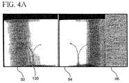
- FIG. 4Ais a schematic view of the bi-plane imaging displays from the interface shown in FIG. 2 , illustrating the identification of a point.
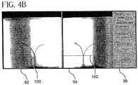
- FIG. 4Bis a schematic view of the bi-plane imaging displays from the interface shown in FIG. 2 , illustrating the identification of a point.
- FIG. 4Cis a schematic view of the bi-plane imaging displays from the interface shown in FIG. 2 , illustrating the identification of a point.
- FIG. 5is an enlarged view of the control panel for the interface shown in FIG. 2 ;
- FIG. 6is a graph showing the points that the fixed length distal end portion of a medical device can contact in a plane
- FIG. 7is a representation of the distal end portion of the medical device, showing points x 1 , x 2 , x 3 , and x 4 ;
- FIG. 8is a representation of the relation between the direction vectors and the field vector
- FIG. 9is a representation of the relation between the direction vectors and ⁇ right arrow over (w) ⁇ , the unit vector orthogonal to ⁇ right arrow over (v) ⁇ and ⁇ right arrow over (n) ⁇ 1 ;
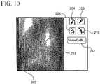
- FIG. 10is representation of a display for an alternate display for a second embodiment of a user interface, that selectively employs a virtual medical device display;
- FIG. 11is a representation of an alternate display for a second embodiment of a user interface that selectively employs a virtual medical device display.
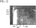
- FIG. 12is a representation of a display from a third embodiment of a user interface, with screen buttons:
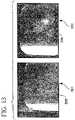
- FIG. 13is a representation of the LAO and RAO images from the third embodiment of the user interface
- FIG. 14is a representation of the RAO image of the third embodiment of the user interface in target mode, showing the target cursor, the target, and the virtual device;
- FIG. 15is representation of the LAO and RAO images from the third embodiment of the user interface in target mode, showing the virtual device extending to a selected target;
- FIG. 16is a representation of the LAO image of third embodiment of the user interface, showing the virtual device after the change in control has been effected;
- FIG. 17is a representation of the LAO image of the third embodiment of the user interface, showing a further change in the virtual device after a prior change in control has been affected.
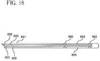
- FIG. 18is a side elevation view of a medical device constructed according to the principles of this invention, and adapted for control by various embodiments of this invention.
- the virtual device interface of the present inventioncan be used with any type of remotely controllable medical device, including for example mechanically, electrically, and magnetically actuatable medical devices.
- One possible use of the inventionis in the control of magnetically actuatable devices, such as with the magnetic navigation system shown in FIG. 1 .
- this inventionis not so limited.
- a Magnetic Resonance imaging systemcould be used, with the catheter being steered by torques generated by the use of changeable magnetic moments located on the device that interact with the static magnetic field of the Magnetic Resonance imaging system.
- any other imaging modality or actuation modalitycould be employed.
- a magnetic surgery systemis set up in the procedure room 50 where the patient is located, and in a control room 52 .
- the control room 52is preferably adjacent the procedure room 50 , and there may be a window 54 between the control room and the procedure room to permit direct observation of the patient, however the control room could be remote from the patient, and with the aid of the present interface, a physician could conduct a procedure on a patient in the procedure from a control room on a different floor, in a different building, or even in a different city.
- the magnetic surgery systemcomprises a patient bed 56 , and a magnetic navigation system 58 comprising opposed magnet units 60 and 62 on opposite sides of the patient bed operated by a processor 64 and controlled by controls 66 adjacent the patient 56 .
- An imaging system 68such as an x-ray imaging system on a C-arm, displays images of the operating region on a set of monitors 70 in the procedure room 50 .
- the interface system of the present inventionprovides a convenient way for a user to operate the magnetic navigation system 58 to control the distal end of a medical device in the operating region inside the patient's body.
- the interfaceincludes a display on, for example, an lcd monitor 72 , and a digital tablet 74 in the procedure room 50 , a processor 76 , a display on, for example, monitor 78 , a key board 80 , and a mouse/digital tablet 82 in the control room 54 .
- Additional displays on monitors 86 and 88can be provided in the procedure room 50 which integrate images from the imaging system 68 with the interface.
- One or more additional monitors 90can be provided in the control room so that the images are available in the control room as well.
- the monitor 90preferably displays a multi-pane display.
- one of the displaysfor example display 90 has panes 92 and 94 for receiving biplane images of the operating region.
- the display 90preferably also includes a control pane 96 .
- the userselects a discrete set of points on the distal end of the medical device to characterize the device.
- the operating regionis imaged with a bi-planar imaging (such as bi-plane fluoroscopy), providing two images of the operating region and of the distal end of the medical device, in different, and preferably mutually perpendicular, planes.
- the bi-plane imaging systemmight provide left anterior oblique (LAO) and right anterior oblique (RAO) images of the operating region, in panes 92 and 94 , respectively.
- Bi-plane imagingcould be provided with a single x-ray source and imaging plate that are moved in tandem to provide imaging in multiple planes.
- the userpreferably identifies the “support” point or “pivot” point x 1 of the distal end portion of the medical device on each of the panes 92 and 94 . By identifying the point in both planes, the user has uniquely identified the point in three dimensional space.
- the userpreferably also identifies the distal end x 4 of the medical device.
- the userpreferably also identifies at least one, and preferably at least two other points x 2 and x 3 , between points x 1 and x 4 . The user could of course identify more points, but the additional accuracy achieved usually does not outweigh the inconvenience to the user.
- the pointscan be identified by manipulating a cursor on each of the bi-planar displays, and clicking on a point, such as point 100 .
- a point 102is displayed on the RAO, along which the point 100 identified in the LAO must lie.
- the userthen uniquely identifies the point in three dimensional space by identifying the desired point 104 along the line 102 displayed on the RAO. The user could begin on the RAO, and complete the point identification process in the LAO.
- Some other methodcan be used to identify points, or the points can be identified automatically, for example using image processing.
- a localization systemcould be employed to characterize the shape of the medical device.
- a magnetic localization systememploying reference transmitters in the procedure room can transmit to one or more receivers on the medical device to locate the receiver and thus the medical device in three-dimensional space (or one or more transmitters on the medical device can transmit to reference receivers in the procedure room).
- Other localization systemsfor example using ultrasound, or electric potential, could be used.
- the pointscan be processed to determine the configuration of the distal end of the medical device. This processing can determine whether the point x 1 is in fact the support point and pivot point of the medical device. For example in a uniform medical device, such as a uniform wall catheter, the distal end portion of the medical device, i.e. the portion distal to the pivot point will assume a generally circular shape. Thus, whether a selected point x 1 is in fact the support point or pivot point can be determined by checking the circularity of the reconstructed curve between the points x 1 , x 2 , x 3 , and x 4 . With other catheter configurations in which the properties are not uniform along the length, the validity of x 1 as the support point or pivot point can be determined by checking the shape of the distal end portion against a calculated or empirically determined shape.
- the processorcan then determine the free length l of the medical device that is distal to the pivot or support point.
- a representation 106 of a virtual medical devicerepresenting the configuration (shape and orientation) of the actual device if a different magnetic field were applied.
- the interfacewould display a representation of a virtual medical device representing the configuration of the actual device as if the control parameter(s) were changed as selected by the user).
- This representationcan be superimposed over the images of the operating region in panes 92 and 94 .
- the usercan select a desired new magnetic field, and then see the configuration of the distal end of the medical device as if the new field were applied, before the new field is applied, and make appropriate adjustments.
- a variety of systems and methodshave been devised for identifying the desired direction of the applied magnetic field.
- the usercan identify the starting point and the ending point (for example on displays of a bi-plane imaging system), and the field can be applied in the selected direction.
- the usercould manipulate a vector representation of the desired field direction, or select previously used directions, or select directions associated with previously identified points (with other remotely controllable medical devices the user can manipulate appropriate control parameters to change the configuration of the device).
- the resulting configuration of the medical devicewas merely a conjecture of the user, based upon experience. With the present method a display of the configuration that the distal end of the medical device should assume when the desired field is applied can be made before the field is actually applied.
- this surface 108represents all the possible points that the distal end of the medical device can reach with only changes to one or more selected control parameters, such as the magnetic field direction and/or intensity.
- this surface 108has a generally parabolic shape.
- This surface 108can also be displayed, and the user can identify a point on this surface, and through processing the system can determine the correct field to apply to cause the distal end of the medical device to reach the selected point. The user can orient the device in the desired direction and reach a point slightly beyond the surface by advancing the medical device slightly. As shown in FIG.
- the systemcan even generate and display surfaces 108 ′ and 108 ′′ of possible points for different free lengths l′ and l′′, so that if the surface representing the current set of possible points does not reach the desired location, the user can select from a surface of a different set of possible points, and either manually adjust the free length l, or if the system is equipped with a mechanized advancer mechanism, allow the system to automatically adjust the free length l.
- the system and method of this inventionalso allow the user to change the configuration of the displayed representation 106 of the medical device, and apply the field to achieve the desired configuration.
- the displaycan be coupled with controls that change the configuration of the displayed virtual image 106 of the distal end portion of the medical device.
- These controlscan be for example, controls that change the deflection and rotation of the distal end of the device.
- these controlsmay be implemented by screen controls 110 and 112 , which can be operated by pointing, clicking and dragging the control to change the degree of deflection and to change the degree of rotation.
- These controls 110 and 112are similar to the controls provided on conventional mechanically navigable devices.
- the controlscould be provided in a catheter handle, similar to conventional catheter handles, which the user can manipulate to change the deflection and rotation of the distal end of the medical device.
- the usercan apply the appropriate field, for example by pointing and clicking on a virtual button 114 (or other control), to apply the magnetic field.
- the systemcan operate in a continuous mode, in which the configuration of the distal end portion of the medical automatically changes upon a change in the displayed image 106 , without the need to operate button 114 ).
- the possible configurations of the displayed virtual deviceare preferably limited to configurations which can be achieved with possible applied magnetic fields, so that user cannot manipulate the virtual device into a configuration that cannot be achieved. This could be built into the controls as well, so that the controls will not allow the user to manipulate the image 106 of the virtual device into a configuration that cannot be physically achieved.
- the processorcan determine the appropriate applied field for a given configuration.
- the usercan specify a configuration, or more preferably a target point, and the interface can determine the control parameters (e.g., magnetic field direction, magnetic field strength, and free length) to reach the target.
- the interfacedisplays the hypothetical new configuration and if satisfactory, the user can accept it, and the interface-determined control parameter applied to reach the target.
- the systemcan store the properties of various types of medical devices, and one of these stored values could be used in the mathematical model that determines the shape of the display 106 of the virtual medical device.
- the usercan select some of these stored values, and as shown in FIG. 5 , the pane 96 can also include a window 116 to display indicia identifying the stored values being used.
- the panecan also include displays 118 of the magnetic field direction currently being applied.
- the interfaceemploys some model of the medical device.
- the following descriptionillustrates a model in the simple case of a flexible device with uniform elastic properties and with a single permanent magnet located at the device tip.
- the model and detailsgeneralize in a manner that may be determined by those skilled in the art to the case when non-uniform elastic properties and more than one magnet are employed, or when alternative modes of device actuation are used.
- the configuration of the medical devicecan be represented as follows:
- the distal end portionwill generally assume a circular configuration.
- the selection of the points, and particularly the pivot point x 1can be validated by ensuing that they lie substantially along a circle. (For not uniform devices, some other check can be performed on the points).
- chord lengthis given by:
- chord length d′2 ⁇ l ⁇ ⁇ sin ⁇ ⁇ 2 [ 16 ] If the points lie along a circle, the chord length d′ should be close to c ⁇
- the curve of the medical devicecan be estimated as follows:
- the curve of the medical deviceis defined by:
- x ⁇ ′x ⁇ 1 + l ⁇ ⁇ ( 1 - cos ⁇ ⁇ ⁇ ′ ) ⁇ v ⁇ + l ⁇ ⁇ sin ⁇ ⁇ ⁇ ′ ⁇ n ⁇ 1 [ 19 ] for 0 ⁇ ′ ⁇
- the envelope or surface of the tip as field direction variescan be determined, based upon the following formula for tip position:
- x ⁇ tipx ⁇ 1 + l ⁇ ⁇ ( 1 - cos ⁇ ⁇ ⁇ ) ⁇ v ⁇ + l ⁇ ⁇ sin ⁇ ⁇ ⁇ ⁇ n ⁇ 1 [ 20 ]
- the field direction that take the tip to that locationmay be computed as follows:
- u ⁇ 1( z ⁇ - x ⁇ 1 ) ⁇ z ⁇ - x ⁇ 1 ⁇ [ 21 ]
- ⁇ _cos - 1 ⁇ ( u ⁇ 1 ⁇ n ⁇ 1 ) [ 22 ]
- ⁇ _⁇ _ + sin - 1 ⁇ ( ⁇ ⁇ ⁇ ⁇ _ MBl ) [ 24 ]
- An “accessible surface”may also be defined by rotating the envelope obtained in equation 25 about ⁇ right arrow over (n) ⁇ 1 .
- ⁇ stan - 1 ⁇ ( u ⁇ ⁇ w ⁇ u ⁇ ⁇ v ⁇ ) [ 29 ]
- FIG. 10A second embodiment of user interface is illustrated in FIG. 10 .
- the interface of the second embodimentis adapted to help a user control a magnetic navigation system that applies a magnetic field to an operating region in a patient to control the direction of a magnetic medical device in the operating region.
- An advancer/retractor mechanismis preferably also provided for the controlled advancement/retraction of the medical device.
- the useris presented an interface with several virtual or real buttons, which the user can operate using a mouse, track ball, space ball, joy stick, tablet, or other input device.
- Operating button 200initiates the navigation under the present invention, and a window (or other message) is displayed, prompting the user to use the input device to identify a number of points on the medical device on the display 202 , including an image 203 of the medical device including the anchor point.
- the useridentifies points, for example, by positioning the cursor over the medical device on the display 202 .
- the inventorshave determined that four points is an appropriate balance between user effort and accuracy in characterizing the medical device to be navigated, but other numbers of points could also be used.
- the points identifiedare checked or qualified (as described above) and a window (or other message) alerts the user if one or more points are not properly identified.
- the processor implementing the interfacecan characterize the medical device.
- the usercan then use the input device to operate direction control buttons.
- buttons 204 and 206for increasing and decreasing the deflection of the medical device
- buttons 208 and 210for rotating the medical device.
- the interfacecan be operated in a discrete navigation mode, a continuous navigation mode, or the interface can allow the user to switch between discrete and continuous navigation.
- the userclicks on the buttons 204 , 206 , 208 , or 210 , and the image 212 of the a virtual device is superposed over the display 202 showing the configuration of the medical device with the specified new magnetic field applied.
- a controlsuch as a button
- the useroperates a control (such as a button) to activate the magnetic navigation system and apply the specified field, causing the actual medical device to assume substantially the configuration and position represented by the image 212 of the virtual device.
- the usercould operate in a continuous navigation mode, changes in the direction specified by operating buttons 204 , 206 , 208 , and 210 are automatically implemented, moving the medical device.
- the usermay enter the continuous navigation mode, for example, by holding down a control button.
- the buttons 204 , 206 , 208 , and 210preferably can be operated to change deflection and rotation in predetermined, discrete amounts, which preferably can be customized by the user, or can be held down to continuously change the deflection and rotation to the limits of the navigation system.
- Many other mappings besides separate control of rotation and deflection of the deviceare possible.
- the device tipcould be controlled or actuated suitably to move within a chosen plane.
- a joystickis provided for interactive device control purposes.
- the userwould select from a set of possible mappings from joystick deflections to changes in actuation control variables that would modify the configuration of the device.
- the magnetic fieldwould be driven from the joystick.
- Visual feedback from an imaging systemthat could employ X-ray, Magnetic Resonance Imaging, Ultrasound or other imaging modalities known to practitioners of the art provides the user with the device configuration, so that the device may be driven interactively by the user to reach a desired target.
- Other embodimentsmay use spaceballs or a variety of other input devices, including those that are custom-built, for interactive remote control of device actuation.
- the interfacealso allows the user to click on a point in the display to mark a target point 214 on the two dimensional display.
- the interfacedetermines the magnetic field required of the magnetic navigation system and extension or retraction of the medical device (which is preferably controlled by an automated advancing/retracting system) required to reach the target point 214 , and displays an image 216 of a virtual device with the calculated magnetic field applied, and with the appropriate adjustment in length made.
- the userthen operates a control (such as a button), so that calculated field and adjustments in length are applied.
- the usercould operate in a continuous navigation mode (such as by holding down another button on a joystick) so that the applied magnetic field and device length automatically change to bring the distal end of the medical device to the point 214 identified by clicking on the display 202 .
- the distal end of the medical devicemay not be precisely where the user intended.
- the usercan switch to another display (if biplane imaging of the operating region is available) to refine the position.
- the usercan identify the target point on each image, uniquely identifying the point in three dimensional space.
- the interfaceassists the selection of a proper point in the second image.
- the cursor color or shapecan indicate when the cursor is over a valid or invalid position based upon the user's selection on the other display.
- the magnetic navigation systemapplies the required field to achieve the specified target point when the user actuates an apply field button.
- the magnetic navigation systemautomatically begins to apply the required field to achieve the specified target point as soon as the target point is properly specified.
- the userpreferably has to hold down a button to remain in the continuous navigation mode, and when the button is released the magnetic navigation system ceases movement.
- the buttoncould be a trigger button on the joystick.
- the apply field button used in the discrete navigation mode and the continuous navigation button used in the continuous navigation modecan be the same.
- the usercan make minor adjustments to the position using the buttons 204 , 206 , 208 , and 210 .
- the systemcan automatically interpret further pointing and clicking on the display 202 as an indication that the user is identifying a target point 214 .
- a buttoncan be provided on the display or on the input device for the user to turn on the target mode.
- buttons 204 , 206 , 208 , and 210the user can input directional changes with a joystick. For example, moving the joystick forward and backward can increase and decrease the deflection, and moving the joystick left and right (or twisting the joystick) can cause rotation. Likewise, it is possible to employ other modes of mapping from the joystick to device actuation. As with using the buttons above, the user can operate in discrete or continuous mode. When operating in discrete mode, the user uses the joystick to position a virtual image 212 on the display 202 , and when satisfied with the position, operates a control (such as a button on the joy stick) to cause the navigation system to apply the magnetic field.
- a controlsuch as a button on the joy stick
- the userWhen operating in the continuous mode, the user operates a control (such as holding down a button on the joystick) so that changes indicated by the movement of the joystick are automatically implemented, with the magnetic navigation system moving in response to change the fields as required.
- a controlsuch as holding down a button on the joystick
- the magnetic navigation systemmoving in response to change the fields as required.
- the medical deviceresponds interactively as the user operates the joystick.
- advancement of the medical deviceis preferably separately controlled by the user, for example with a toggle switch on the joystick so that a single joystick can be used for both device steering and device advancement or retraction, or with a separate button on the display 202 .
- the interfacepreferably controls both the magnetic navigation system and the advancer system, so that the device is directly computer controlled.
- advancement of the medical device and device deflections or shape changesare controlled by the user from separate joysticks.
- Various other embodiments and modes of usemay be conceived by those skilled in the art.
- FIG. 11shows a display 300 from another implementation of the interface system of the second embodiment.
- the display 300includes two bi-plane images 302 and 304 of the operating region.
- the displayalso includes a control pane 306 .
- the control panemay include a box 308 in which the user can select or specify the stiffness of the medical device; alternatively the medical device type may be selected from a menu of medical devices whose stiffness value is pre-programmed into the system.
- a computer processorcan use the stiffness to determine the configuration of the medical device in an applied magnetic field, both to generate virtual images of the device under specified magnetic fields, and to calculate the applied field to reach a particular target point.
- the control pane 306also includes a field display 309 , with the coordinates of the current magnetic field direction, and pick boxes for selecting the point of application of the field.
- the control panehas free length box 310 , which allows the user to select the free length of the medical device from the end of its sheath. Arrows 312 and 314 allow the user to increase and decrease the specified length, which is implemented by an advancer/retractor mechanism.
- the control pane 306also includes slide controls 316 and 318 for controlling the degree of deflection and rotation (like buttons 204 206 , 208 and 210 ).
- An apply field button 320allows the user to apply the field specified by the virtual device in the displays.
- a conform to field button 322causes the virtual device model to predict and show the shape that would be caused by application of an input magnetic field.
- a get live button 324updates the images 302 and 304 .
- a target mode button 326allows the user to enter the target mode (as described above), so that pointing and clicking on the displays 302 and 304 identifies a point which the virtual medical device moves to in the discrete mode, or which the actual medical device moves in the continuous mode.
- buttons 411 and 412are provided as alternate modes of control of a magnetic navigation system.
- Button 411when selected enables defining the direction of the magnetic field in three dimensional space by specification of the direction in two projections (commonly the LAO and RAO perspectives familiar to interventional surgeons).
- the deviceWhen the corresponding magnetic field is applied to steer a medical device, the device tends to align itself with the magnetic field but with a certain angular lag as dictated by the elastic and magnetic properties of the device.
- button 412enables direct selection of a target location that the device can move to.
- a “Mark catheter base” button 413shown highlighted in FIG. 12 ) with a mouse click.
- Thisenables the user to indicate (by drawing with a pen-tablet or by suitably dragging a mouse) the pivot or point of support of the device as well as the pivot direction, by suitably drawing a line in two projected X-ray views.
- a catheter 419can be seen to extend from a guide sheath 422 .
- the line 420 drawn by the userindicates the pivot point to be the distal tip of the sheath and the direction in which the device 419 is extended at the pivot point.
- FIG. 13shows the pivot point and direction marked by lines 505 and 506 respectively in RAO and LAO views 501 and 502 .
- This processin effect provides x 1 and n 1 to the system.
- the userselects the target button 412 as shown in FIG. 14 .
- Thisprovides to the user a “Target” cursor 601 that enables selection of a point 602 in three dimensional space from two X-ray projections.
- This pointis the desired anatomical target point that the user wishes to steer the medical device to.
- the computercalculates the requisite field direction and insertion length from equations (25) and (32).
- the corresponding shape of the deviceis also computed and displayed as a dashed curve 603 .
- FIG. 15shows a desired target point in RAO and LAO projections respectively as 602 and 602 a together with associated projections of the device shape 603 and 603 a 11 respectively.
- the required field direction and insertion lengthmay be automatically applied by the system upon the press of a button.
- the field directionmay be applied directly by the system while the user continuously controls the advancement or retraction of the device.
- the device curvemay be updated to be shown as a solid curve, perhaps in a different color, to indicate that the desired change of controls has been effected.
- FIG. 16shows an LAO perspective of such an updated device curve 650 together with the user-defined pivot direction 648 and the desired target location 652 .
- the device shapemay be interactively manipulated by the user as described above.
- One convenient implementationuses keyboard buttons for increasing or decreasing deflection of the virtual device and for rotating it clockwise or anti-clockwise about the pivot direction.
- the device shapeis continuously computed and updated in the projected displays as well as possibly in a three dimensional display during this process of user adjustment.
- the corresponding manipulated virtual device 702is shown in an LAO perspective in FIG. 17 together with the current device configuration 701 and an updated location 703 for the device tip as the use manipulates the virtual device.
- the corresponding controlsmay be applied at the touch of an “Apply” button, or alternatively the system may apply the controls (magnetic field and insertion/retraction in one embodiment) in user-defined steps every time a keyboard button is pressed.
- Another convenient implementation of continuous controluses a joystick or other input device together with a mapping function to convert joystick movements to changes in control inputs, causing the device to respond continuously to joystick movements.
- the usercould, together with moving or deflecting the joystick, press and hold a “trigger” button to cause the changes in control inputs to be applied.
- the userobserves (on an X-ray image or other mode of visualization) the device response to joystick movements and may interactively stop device response when a desired device configuration has been attained, for example by releasing a “trigger” button on the joystick.
- the actuation system employed to steer or orient the flexible devicecan take several different forms such as magnetic actuation by external magnetic fields, mechanical actuation through the use of steering cables or other force transmission elements within the device, device actuation using piezoelectric materials or electrostrictive polymers such as silicone elastomers, actuation with magnetostrictive elements embedded in the device, or other technologies known to practitioners of the art.
- the actuation systemcan use magnetic fields generated by external magnets to orient magnets incorporated in the distal portion of the device.
- the interaction of the external field with the device magnetsserves to orient the device in controllable fashion by controlling the externally applied magnetic field.
- the external magnetscould employ either permanent magnets or electromagnets possibly employing superconductivity to produce strong magnetic fields.
- FIG. 1shows a schematic illustration of such a system and device.
- FIG. 18shows a flexible device 851 which incorporates electrostrictive elements 854 and 855 .
- Electrical leads 858 , 859 and 865 , 866connect the elements 854 and 855 respectively to a voltage source 856 .
- the electrostrictive element 854is sandwiched between rings 860 and 862 .
- the electrostrictive element 854decreases in length, forcing the flexible device to bend in the plane defined by the device axis and the orientation of the electrostrictive element relative to the device axis.
- the amount of bendingcan be controlled by varying the applied voltage.
- the shortening of element 855forces the device to bend in the opposite direction.
- the bending plane of the deviceit may be useful to determine the bending plane of the device. This is relevant where a non-magnetic steering mechanism is used to orient the device. This may be done by employing an imaging method such as X-ray imaging or by using a localization sensor embedded in the device. If a localization sensor which gives complete position and orientation of the device is used, the orientation of the actuation mechanism such as steering cable or electrostrictive element is known in a reference configuration, the corresponding orientation in a general configuration may be obtained by processing the data obtained from the localization sensor. Thus the bending plane of the device in three dimensional space may be determined. Alternatively, from imaging such as fluoroscopy, the change in the tangent vector to the device tip upon a small change in an actuation control variable may be recorded, which also provides information needed to determine the bending plane in three dimensional space.
- Knowledge of the bending planecan be used to control the device for targeting purposes and for configurational changes with the aid of a computational model in a manner similar to that described above.
- the actuation system coordinatesmay be registered to the imaging system coordinates and to the localization system coordinates by means of several methods known to those skilled in the art.
- the actuation systemmay employ external magnetic fields, in which case the source of the fields such as an external magnet could be mechanically registered to the imaging system by the use of suitably placed markers placed in known positions with respect to the actuation system.
- These positionsmay also be ascribed coordinates in the reference frame of the imaging system since information from multiple imaging projections or from three dimensional imaging would be available from the imaging system.
- the positions of three markers determined in both coordinate systemssuffices to generate a rigid coordinate transformation (rotation and translation) which is the requisite registration. Additional markers may be used for improved accuracy as desired.
- a device localization systemit could be used to determine the coordinates of known markers with respect to the localization system as well, thence providing a mutual registration of the various distinct coordinate frames employed by the various systems. In practice, such a registration would be performed at the start of a medical procedure. Subsequent movement of the patient table may be tracked to within a suitable accuracy to permit updated registrations as may be required on a regular basis during a clinical procedure.
- a magnetic actuation systemhas been discussed in the above for non-limiting illustrative purposes, various alternative actuation systems may be deployed and registered as needed according to the methods taught here.
- a device employing piezoelectric actuatorsmay use a coordinate frame in common with an X-ray imaging system, requiring only registration to a device localization system.
- the markers in questionmay be either mechanically placed by the user or may be based on anatomical locations as pinpointed by the user.
Landscapes
- Health & Medical Sciences (AREA)
- Surgery (AREA)
- Engineering & Computer Science (AREA)
- Life Sciences & Earth Sciences (AREA)
- Biomedical Technology (AREA)
- Robotics (AREA)
- Nuclear Medicine, Radiotherapy & Molecular Imaging (AREA)
- Heart & Thoracic Surgery (AREA)
- Medical Informatics (AREA)
- Molecular Biology (AREA)
- Animal Behavior & Ethology (AREA)
- General Health & Medical Sciences (AREA)
- Public Health (AREA)
- Veterinary Medicine (AREA)
- Magnetic Resonance Imaging Apparatus (AREA)
Abstract
Description
The unit tangent vectors at points x1and x4({right arrow over (n)}1and {right arrow over (n)}4) may be estimated as follows:
{right arrow over (p)}=({right arrow over (x)}4−{right arrow over (x)}1)/|{right arrow over (x)}4−{right arrow over (x)}1| [11]
{right arrow over (q)}1={right arrow over (n)}1×{right arrow over (n)}4 [12]
{right arrow over (q)}2={right arrow over (n)}1×{right arrow over (p)} [13]
φ=cos−1({right arrow over (q)}1·{right arrow over (q)}2) [14]
where B is the magnitude of the field strength and l is the length of the medical device between {right arrow over (x)}1and {right arrow over (x)}4.
If the points lie along a circle, the chord length d′ should be close to c≡|{right arrow over (x)}4−{right arrow over (x)}1|, for example, within ten percent, or
{right arrow over (v)}′≡{right arrow over (n)}4−{right arrow over (n)}1cos θ [17]
{right arrow over (v)}={right arrow over (v)}′/|{right arrow over (v)}′| [18]
for 0≦θ′≦θ
Varying θ from 0 to θmas(=lMB/β) gives the envelope or locus of tip positions as the field is varied.
Determining the Field Direction for a Selected Point
{right arrow over (u)}B={right arrow over (n)}1cos
defines a surface of revolution about n1that is the surface accessible to the tip by changing the field direction by varying θ and ξ, a surface is generated analogous to generating a sphere with longitude and latitude.
Generating the Field Direction to any Point on the Surface
uB,S={right arrow over (n)}1cos ψ+{right arrow over (v)}R,Ssin {right arrow over (ψ)} [27]
where {right arrow over (v)}R,Sis obtained from:
{right arrow over (v)}R,S=cos ξs{right arrow over (v)}+sin ξs{right arrow over (w)} [28]
where
Given Equations 28 and 29:
{right arrow over (u)}B,S={right arrow over (n)}1cos
and
δl=(
is the change in inserted length which together with the change in field direction will take the end of the medical device to the desired location.
Claims (60)
Priority Applications (5)
| Application Number | Priority Date | Filing Date | Title |
|---|---|---|---|
| US10/448,273US7630752B2 (en) | 2002-08-06 | 2003-05-29 | Remote control of medical devices using a virtual device interface |
| AU2003258059AAU2003258059A1 (en) | 2002-08-06 | 2003-08-01 | Virtual device interface control for medical devices |
| PCT/US2003/024437WO2004012646A2 (en) | 2002-08-06 | 2003-08-01 | Virtual device interface control for medical devices |
| JP2005506097AJP2006519629A (en) | 2002-08-06 | 2003-08-01 | Remote control of medical devices using virtual device interfaces |
| EP03767183AEP1631191A4 (en) | 2002-08-06 | 2003-08-01 | Virtual device interface control for medical devices |
Applications Claiming Priority (2)
| Application Number | Priority Date | Filing Date | Title |
|---|---|---|---|
| US40167002P | 2002-08-06 | 2002-08-06 | |
| US10/448,273US7630752B2 (en) | 2002-08-06 | 2003-05-29 | Remote control of medical devices using a virtual device interface |
Publications (2)
| Publication Number | Publication Date |
|---|---|
| US20040068173A1 US20040068173A1 (en) | 2004-04-08 |
| US7630752B2true US7630752B2 (en) | 2009-12-08 |
Family
ID=32045199
Family Applications (1)
| Application Number | Title | Priority Date | Filing Date |
|---|---|---|---|
| US10/448,273Active2028-09-06US7630752B2 (en) | 2002-08-06 | 2003-05-29 | Remote control of medical devices using a virtual device interface |
Country Status (1)
| Country | Link |
|---|---|
| US (1) | US7630752B2 (en) |
Cited By (155)
| Publication number | Priority date | Publication date | Assignee | Title |
|---|---|---|---|---|
| US20060094956A1 (en)* | 2004-10-29 | 2006-05-04 | Viswanathan Raju R | Restricted navigation controller for, and methods of controlling, a remote navigation system |
| US20080065061A1 (en)* | 2006-09-08 | 2008-03-13 | Viswanathan Raju R | Impedance-Based Cardiac Therapy Planning Method with a Remote Surgical Navigation System |
| US20090027489A1 (en)* | 2005-03-29 | 2009-01-29 | Takashi Takemura | Signal Processing Apparatus for Electronic Endoscope and Electronic Endoscope Apparatus |
| US7961926B2 (en) | 2005-02-07 | 2011-06-14 | Stereotaxis, Inc. | Registration of three-dimensional image data to 2D-image-derived data |
| US20110196377A1 (en)* | 2009-08-13 | 2011-08-11 | Zimmer, Inc. | Virtual implant placement in the or |
| US8202244B2 (en) | 2005-07-11 | 2012-06-19 | Catheter Robotics, Inc. | Remotely controlled catheter insertion system |
| US8308628B2 (en) | 2009-11-02 | 2012-11-13 | Pulse Therapeutics, Inc. | Magnetic-based systems for treating occluded vessels |
| US8369934B2 (en) | 2004-12-20 | 2013-02-05 | Stereotaxis, Inc. | Contact over-torque with three-dimensional anatomical data |
| US9078685B2 (en) | 2007-02-16 | 2015-07-14 | Globus Medical, Inc. | Method and system for performing invasive medical procedures using a surgical robot |
| US9530219B2 (en) | 2014-07-02 | 2016-12-27 | Covidien Lp | System and method for detecting trachea |
| US9533121B2 (en) | 2013-02-26 | 2017-01-03 | Catheter Precision, Inc. | Components and methods for accommodating guidewire catheters on a catheter controller system |
| US9603668B2 (en) | 2014-07-02 | 2017-03-28 | Covidien Lp | Dynamic 3D lung map view for tool navigation inside the lung |
| US9700698B2 (en) | 2013-09-27 | 2017-07-11 | Catheter Precision, Inc. | Components and methods for a catheter positioning system with a spreader and track |
| US9707377B2 (en) | 2008-01-16 | 2017-07-18 | Catheter Precision, Inc. | Remotely controlled catheter insertion system |
| US9724493B2 (en) | 2013-08-27 | 2017-08-08 | Catheter Precision, Inc. | Components and methods for balancing a catheter controller system with a counterweight |
| US9750577B2 (en) | 2013-09-06 | 2017-09-05 | Catheter Precision, Inc. | Single hand operated remote controller for remote catheter positioning system |
| US9754367B2 (en) | 2014-07-02 | 2017-09-05 | Covidien Lp | Trachea marking |
| US9770216B2 (en) | 2014-07-02 | 2017-09-26 | Covidien Lp | System and method for navigating within the lung |
| US9782229B2 (en) | 2007-02-16 | 2017-10-10 | Globus Medical, Inc. | Surgical robot platform |
| US9795764B2 (en) | 2013-09-27 | 2017-10-24 | Catheter Precision, Inc. | Remote catheter positioning system with hoop drive assembly |
| US9836848B2 (en) | 2014-07-02 | 2017-12-05 | Covidien Lp | System and method for segmentation of lung |
| US9883878B2 (en) | 2012-05-15 | 2018-02-06 | Pulse Therapeutics, Inc. | Magnetic-based systems and methods for manipulation of magnetic particles |
| US9993614B2 (en) | 2013-08-27 | 2018-06-12 | Catheter Precision, Inc. | Components for multiple axis control of a catheter in a catheter positioning system |
| US9999751B2 (en) | 2013-09-06 | 2018-06-19 | Catheter Precision, Inc. | Adjustable nose cone for a catheter positioning system |
| US10080615B2 (en) | 2015-08-12 | 2018-09-25 | Globus Medical, Inc. | Devices and methods for temporary mounting of parts to bone |
| US10117632B2 (en) | 2016-02-03 | 2018-11-06 | Globus Medical, Inc. | Portable medical imaging system with beam scanning collimator |
| US10136954B2 (en) | 2012-06-21 | 2018-11-27 | Globus Medical, Inc. | Surgical tool systems and method |
| US10231791B2 (en) | 2012-06-21 | 2019-03-19 | Globus Medical, Inc. | Infrared signal based position recognition system for use with a robot-assisted surgery |
| US10292778B2 (en) | 2014-04-24 | 2019-05-21 | Globus Medical, Inc. | Surgical instrument holder for use with a robotic surgical system |
| US10357184B2 (en) | 2012-06-21 | 2019-07-23 | Globus Medical, Inc. | Surgical tool systems and method |
| US10448910B2 (en) | 2016-02-03 | 2019-10-22 | Globus Medical, Inc. | Portable medical imaging system |
| US10537713B2 (en) | 2009-05-25 | 2020-01-21 | Stereotaxis, Inc. | Remote manipulator device |
| US10573023B2 (en) | 2018-04-09 | 2020-02-25 | Globus Medical, Inc. | Predictive visualization of medical imaging scanner component movement |
| US10569794B2 (en) | 2015-10-13 | 2020-02-25 | Globus Medical, Inc. | Stabilizer wheel assembly and methods of use |
| US10580217B2 (en) | 2015-02-03 | 2020-03-03 | Globus Medical, Inc. | Surgeon head-mounted display apparatuses |
| US10646283B2 (en) | 2018-02-19 | 2020-05-12 | Globus Medical Inc. | Augmented reality navigation systems for use with robotic surgical systems and methods of their use |
| US10660712B2 (en) | 2011-04-01 | 2020-05-26 | Globus Medical Inc. | Robotic system and method for spinal and other surgeries |
| US10675094B2 (en) | 2017-07-21 | 2020-06-09 | Globus Medical Inc. | Robot surgical platform |
| US10709352B2 (en) | 2015-10-27 | 2020-07-14 | Covidien Lp | Method of using lung airway carina locations to improve ENB registration |
| US10772532B2 (en) | 2014-07-02 | 2020-09-15 | Covidien Lp | Real-time automatic registration feedback |
| US10813704B2 (en) | 2013-10-04 | 2020-10-27 | Kb Medical, Sa | Apparatus and systems for precise guidance of surgical tools |
| US10842453B2 (en) | 2016-02-03 | 2020-11-24 | Globus Medical, Inc. | Portable medical imaging system |
| US10866119B2 (en) | 2016-03-14 | 2020-12-15 | Globus Medical, Inc. | Metal detector for detecting insertion of a surgical device into a hollow tube |
| US10893912B2 (en) | 2006-02-16 | 2021-01-19 | Globus Medical Inc. | Surgical tool systems and methods |
| US10898252B2 (en) | 2017-11-09 | 2021-01-26 | Globus Medical, Inc. | Surgical robotic systems for bending surgical rods, and related methods and devices |
| US10925681B2 (en) | 2015-07-31 | 2021-02-23 | Globus Medical Inc. | Robot arm and methods of use |
| US10939968B2 (en) | 2014-02-11 | 2021-03-09 | Globus Medical Inc. | Sterile handle for controlling a robotic surgical system from a sterile field |
| US10945742B2 (en) | 2014-07-14 | 2021-03-16 | Globus Medical Inc. | Anti-skid surgical instrument for use in preparing holes in bone tissue |
| US10973594B2 (en) | 2015-09-14 | 2021-04-13 | Globus Medical, Inc. | Surgical robotic systems and methods thereof |
| USD916750S1 (en) | 2014-07-02 | 2021-04-20 | Covidien Lp | Display screen or portion thereof with graphical user interface |
| US10986990B2 (en) | 2015-09-24 | 2021-04-27 | Covidien Lp | Marker placement |
| US11045267B2 (en) | 2012-06-21 | 2021-06-29 | Globus Medical, Inc. | Surgical robotic automation with tracking markers |
| US11045179B2 (en) | 2019-05-20 | 2021-06-29 | Global Medical Inc | Robot-mounted retractor system |
| US11058378B2 (en) | 2016-02-03 | 2021-07-13 | Globus Medical, Inc. | Portable medical imaging system |
| US11109922B2 (en) | 2012-06-21 | 2021-09-07 | Globus Medical, Inc. | Surgical tool systems and method |
| US11116576B2 (en) | 2012-06-21 | 2021-09-14 | Globus Medical Inc. | Dynamic reference arrays and methods of use |
| US11134862B2 (en) | 2017-11-10 | 2021-10-05 | Globus Medical, Inc. | Methods of selecting surgical implants and related devices |
| US11153555B1 (en) | 2020-05-08 | 2021-10-19 | Globus Medical Inc. | Extended reality headset camera system for computer assisted navigation in surgery |
| US11207150B2 (en) | 2020-02-19 | 2021-12-28 | Globus Medical, Inc. | Displaying a virtual model of a planned instrument attachment to ensure correct selection of physical instrument attachment |
| US11224392B2 (en) | 2018-02-01 | 2022-01-18 | Covidien Lp | Mapping disease spread |
| US11253327B2 (en) | 2012-06-21 | 2022-02-22 | Globus Medical, Inc. | Systems and methods for automatically changing an end-effector on a surgical robot |
| US11253216B2 (en) | 2020-04-28 | 2022-02-22 | Globus Medical Inc. | Fixtures for fluoroscopic imaging systems and related navigation systems and methods |
| US11266470B2 (en) | 2015-02-18 | 2022-03-08 | KB Medical SA | Systems and methods for performing minimally invasive spinal surgery with a robotic surgical system using a percutaneous technique |
| US11278360B2 (en) | 2018-11-16 | 2022-03-22 | Globus Medical, Inc. | End-effectors for surgical robotic systems having sealed optical components |
| US11298196B2 (en) | 2012-06-21 | 2022-04-12 | Globus Medical Inc. | Surgical robotic automation with tracking markers and controlled tool advancement |
| US11317978B2 (en) | 2019-03-22 | 2022-05-03 | Globus Medical, Inc. | System for neuronavigation registration and robotic trajectory guidance, robotic surgery, and related methods and devices |
| US11317973B2 (en) | 2020-06-09 | 2022-05-03 | Globus Medical, Inc. | Camera tracking bar for computer assisted navigation during surgery |
| US11317971B2 (en) | 2012-06-21 | 2022-05-03 | Globus Medical, Inc. | Systems and methods related to robotic guidance in surgery |
| US11337742B2 (en) | 2018-11-05 | 2022-05-24 | Globus Medical Inc | Compliant orthopedic driver |
| US11337769B2 (en) | 2015-07-31 | 2022-05-24 | Globus Medical, Inc. | Robot arm and methods of use |
| US11357548B2 (en) | 2017-11-09 | 2022-06-14 | Globus Medical, Inc. | Robotic rod benders and related mechanical and motor housings |
| US11382713B2 (en) | 2020-06-16 | 2022-07-12 | Globus Medical, Inc. | Navigated surgical system with eye to XR headset display calibration |
| US11382549B2 (en) | 2019-03-22 | 2022-07-12 | Globus Medical, Inc. | System for neuronavigation registration and robotic trajectory guidance, and related methods and devices |
| US11382699B2 (en) | 2020-02-10 | 2022-07-12 | Globus Medical Inc. | Extended reality visualization of optical tool tracking volume for computer assisted navigation in surgery |
| US11382700B2 (en) | 2020-05-08 | 2022-07-12 | Globus Medical Inc. | Extended reality headset tool tracking and control |
| US11395706B2 (en) | 2012-06-21 | 2022-07-26 | Globus Medical Inc. | Surgical robot platform |
| US11399900B2 (en) | 2012-06-21 | 2022-08-02 | Globus Medical, Inc. | Robotic systems providing co-registration using natural fiducials and related methods |
| US11419616B2 (en) | 2019-03-22 | 2022-08-23 | Globus Medical, Inc. | System for neuronavigation registration and robotic trajectory guidance, robotic surgery, and related methods and devices |
| US11426178B2 (en) | 2019-09-27 | 2022-08-30 | Globus Medical Inc. | Systems and methods for navigating a pin guide driver |
| US11439444B1 (en) | 2021-07-22 | 2022-09-13 | Globus Medical, Inc. | Screw tower and rod reduction tool |
| US11510684B2 (en) | 2019-10-14 | 2022-11-29 | Globus Medical, Inc. | Rotary motion passive end effector for surgical robots in orthopedic surgeries |
| US11510750B2 (en) | 2020-05-08 | 2022-11-29 | Globus Medical, Inc. | Leveraging two-dimensional digital imaging and communication in medicine imagery in three-dimensional extended reality applications |
| US11523785B2 (en) | 2020-09-24 | 2022-12-13 | Globus Medical, Inc. | Increased cone beam computed tomography volume length without requiring stitching or longitudinal C-arm movement |
| US11529195B2 (en) | 2017-01-18 | 2022-12-20 | Globus Medical Inc. | Robotic navigation of robotic surgical systems |
| US11571265B2 (en) | 2019-03-22 | 2023-02-07 | Globus Medical Inc. | System for neuronavigation registration and robotic trajectory guidance, robotic surgery, and related methods and devices |
| US11571171B2 (en) | 2019-09-24 | 2023-02-07 | Globus Medical, Inc. | Compound curve cable chain |
| US11602402B2 (en) | 2018-12-04 | 2023-03-14 | Globus Medical, Inc. | Drill guide fixtures, cranial insertion fixtures, and related methods and robotic systems |
| US11607149B2 (en) | 2012-06-21 | 2023-03-21 | Globus Medical Inc. | Surgical tool systems and method |
| US11628023B2 (en) | 2019-07-10 | 2023-04-18 | Globus Medical, Inc. | Robotic navigational system for interbody implants |
| US11628039B2 (en) | 2006-02-16 | 2023-04-18 | Globus Medical Inc. | Surgical tool systems and methods |
| US11717350B2 (en) | 2020-11-24 | 2023-08-08 | Globus Medical Inc. | Methods for robotic assistance and navigation in spinal surgery and related systems |
| US11737766B2 (en) | 2014-01-15 | 2023-08-29 | Globus Medical Inc. | Notched apparatus for guidance of an insertable instrument along an axis during spinal surgery |
| US11737831B2 (en) | 2020-09-02 | 2023-08-29 | Globus Medical Inc. | Surgical object tracking template generation for computer assisted navigation during surgical procedure |
| US11744655B2 (en) | 2018-12-04 | 2023-09-05 | Globus Medical, Inc. | Drill guide fixtures, cranial insertion fixtures, and related methods and robotic systems |
| US11794338B2 (en) | 2017-11-09 | 2023-10-24 | Globus Medical Inc. | Robotic rod benders and related mechanical and motor housings |
| US11793570B2 (en) | 2012-06-21 | 2023-10-24 | Globus Medical Inc. | Surgical robotic automation with tracking markers |
| US11793588B2 (en) | 2020-07-23 | 2023-10-24 | Globus Medical, Inc. | Sterile draping of robotic arms |
| US11806084B2 (en) | 2019-03-22 | 2023-11-07 | Globus Medical, Inc. | System for neuronavigation registration and robotic trajectory guidance, and related methods and devices |
| US11813030B2 (en) | 2017-03-16 | 2023-11-14 | Globus Medical, Inc. | Robotic navigation of robotic surgical systems |
| US11819365B2 (en) | 2012-06-21 | 2023-11-21 | Globus Medical, Inc. | System and method for measuring depth of instrumentation |
| US11850009B2 (en) | 2021-07-06 | 2023-12-26 | Globus Medical, Inc. | Ultrasonic robotic surgical navigation |
| US11857266B2 (en) | 2012-06-21 | 2024-01-02 | Globus Medical, Inc. | System for a surveillance marker in robotic-assisted surgery |
| US11857149B2 (en) | 2012-06-21 | 2024-01-02 | Globus Medical, Inc. | Surgical robotic systems with target trajectory deviation monitoring and related methods |
| US11864839B2 (en) | 2012-06-21 | 2024-01-09 | Globus Medical Inc. | Methods of adjusting a virtual implant and related surgical navigation systems |
| US11864857B2 (en) | 2019-09-27 | 2024-01-09 | Globus Medical, Inc. | Surgical robot with passive end effector |
| US11864745B2 (en) | 2012-06-21 | 2024-01-09 | Globus Medical, Inc. | Surgical robotic system with retractor |
| US11872000B2 (en) | 2015-08-31 | 2024-01-16 | Globus Medical, Inc | Robotic surgical systems and methods |
| US11877807B2 (en) | 2020-07-10 | 2024-01-23 | Globus Medical, Inc | Instruments for navigated orthopedic surgeries |
| US11883217B2 (en) | 2016-02-03 | 2024-01-30 | Globus Medical, Inc. | Portable medical imaging system and method |
| US11890066B2 (en) | 2019-09-30 | 2024-02-06 | Globus Medical, Inc | Surgical robot with passive end effector |
| US11911225B2 (en) | 2012-06-21 | 2024-02-27 | Globus Medical Inc. | Method and system for improving 2D-3D registration convergence |
| US11911112B2 (en) | 2020-10-27 | 2024-02-27 | Globus Medical, Inc. | Robotic navigational system |
| US11911115B2 (en) | 2021-12-20 | 2024-02-27 | Globus Medical Inc. | Flat panel registration fixture and method of using same |
| US11918315B2 (en) | 2018-05-03 | 2024-03-05 | Pulse Therapeutics, Inc. | Determination of structure and traversal of occlusions using magnetic particles |
| US11941814B2 (en) | 2020-11-04 | 2024-03-26 | Globus Medical Inc. | Auto segmentation using 2-D images taken during 3-D imaging spin |
| US11944325B2 (en) | 2019-03-22 | 2024-04-02 | Globus Medical, Inc. | System for neuronavigation registration and robotic trajectory guidance, robotic surgery, and related methods and devices |
| US11974886B2 (en) | 2016-04-11 | 2024-05-07 | Globus Medical Inc. | Surgical tool systems and methods |
| US11974822B2 (en) | 2012-06-21 | 2024-05-07 | Globus Medical Inc. | Method for a surveillance marker in robotic-assisted surgery |
| US11992373B2 (en) | 2019-12-10 | 2024-05-28 | Globus Medical, Inc | Augmented reality headset with varied opacity for navigated robotic surgery |
| US11998287B1 (en) | 2019-03-18 | 2024-06-04 | Dopl Technologies Inc. | Platform for facilitating remote robotic medical procedures |
| US12004905B2 (en) | 2012-06-21 | 2024-06-11 | Globus Medical, Inc. | Medical imaging systems using robotic actuators and related methods |
| US12048493B2 (en) | 2022-03-31 | 2024-07-30 | Globus Medical, Inc. | Camera tracking system identifying phantom markers during computer assisted surgery navigation |
| US12064189B2 (en) | 2019-12-13 | 2024-08-20 | Globus Medical, Inc. | Navigated instrument for use in robotic guided surgery |
| US12070286B2 (en) | 2021-01-08 | 2024-08-27 | Globus Medical, Inc | System and method for ligament balancing with robotic assistance |
| US12070276B2 (en) | 2020-06-09 | 2024-08-27 | Globus Medical Inc. | Surgical object tracking in visible light via fiducial seeding and synthetic image registration |
| US12076091B2 (en) | 2020-10-27 | 2024-09-03 | Globus Medical, Inc. | Robotic navigational system |
| US12082886B2 (en) | 2017-04-05 | 2024-09-10 | Globus Medical Inc. | Robotic surgical systems for preparing holes in bone tissue and methods of their use |
| US12089902B2 (en) | 2019-07-30 | 2024-09-17 | Coviden Lp | Cone beam and 3D fluoroscope lung navigation |
| US12103480B2 (en) | 2022-03-18 | 2024-10-01 | Globus Medical Inc. | Omni-wheel cable pusher |
| US12133772B2 (en) | 2019-12-10 | 2024-11-05 | Globus Medical, Inc. | Augmented reality headset for navigated robotic surgery |
| US12150728B2 (en) | 2021-04-14 | 2024-11-26 | Globus Medical, Inc. | End effector for a surgical robot |
| US12161427B2 (en) | 2022-06-08 | 2024-12-10 | Globus Medical, Inc. | Surgical navigation system with flat panel registration fixture |
| US12171443B1 (en) | 2021-03-09 | 2024-12-24 | Pulse Therapeutics, Inc. | Magnetically controlled flow generation |
| US12184636B2 (en) | 2021-10-04 | 2024-12-31 | Globus Medical, Inc. | Validating credential keys based on combinations of credential value strings and input order strings |
| US12178523B2 (en) | 2021-04-19 | 2024-12-31 | Globus Medical, Inc. | Computer assisted surgical navigation system for spine procedures |
| US12201375B2 (en) | 2021-09-16 | 2025-01-21 | Globus Medical Inc. | Extended reality systems for visualizing and controlling operating room equipment |
| US12220176B2 (en) | 2019-12-10 | 2025-02-11 | Globus Medical, Inc. | Extended reality instrument interaction zone for navigated robotic |
| US12220120B2 (en) | 2012-06-21 | 2025-02-11 | Globus Medical, Inc. | Surgical robotic system with retractor |
| US12226169B2 (en) | 2022-07-15 | 2025-02-18 | Globus Medical, Inc. | Registration of 3D and 2D images for surgical navigation and robotic guidance without using radiopaque fiducials in the images |
| US12232820B2 (en) | 2021-12-01 | 2025-02-25 | Globus Medical, Inc. | Extended reality systems with three-dimensional visualizations of medical image scan slices |
| US12238087B2 (en) | 2021-10-04 | 2025-02-25 | Globus Medical, Inc. | Validating credential keys based on combinations of credential value strings and input order strings |
| US12251140B2 (en) | 2012-06-21 | 2025-03-18 | Globus Medical, Inc. | Methods for performing medical procedures using a surgical robot |
| US12262954B2 (en) | 2012-06-21 | 2025-04-01 | Globus Medical, Inc. | Surgical robotic automation with tracking markers |
| US12310683B2 (en) | 2012-06-21 | 2025-05-27 | Globus Medical, Inc. | Surgical tool systems and method |
| US12318150B2 (en) | 2022-10-11 | 2025-06-03 | Globus Medical Inc. | Camera tracking system for computer assisted surgery navigation |
| US12329469B2 (en) | 2014-12-02 | 2025-06-17 | Globus Medical Inc. | Robot assisted volume removal during surgery |
| US12329391B2 (en) | 2019-09-27 | 2025-06-17 | Globus Medical, Inc. | Systems and methods for robot-assisted knee arthroplasty surgery |
| US12329593B2 (en) | 2012-06-21 | 2025-06-17 | Globus Medical, Inc. | Surgical robotic automation with tracking markers |
| US12354263B2 (en) | 2022-07-15 | 2025-07-08 | Globus Medical Inc. | Registration of 3D and 2D images for surgical navigation and robotic guidance without using radiopaque fiducials in the images |
| US12394086B2 (en) | 2022-05-10 | 2025-08-19 | Globus Medical, Inc. | Accuracy check and automatic calibration of tracked instruments |
| US12396692B2 (en) | 2019-09-24 | 2025-08-26 | Globus Medical, Inc. | Compound curve cable chain |
| US12408929B2 (en) | 2019-09-27 | 2025-09-09 | Globus Medical, Inc. | Systems and methods for navigating a pin guide driver |
| US12414752B2 (en) | 2020-02-17 | 2025-09-16 | Globus Medical, Inc. | System and method of determining optimal 3-dimensional position and orientation of imaging device for imaging patient bones |
| US12430760B2 (en) | 2021-10-20 | 2025-09-30 | Globus Medical, Inc. | Registering intra-operative images transformed from pre-operative images of different imaging-modality for computer assisted navigation during surgery |
| US12444045B2 (en) | 2022-05-12 | 2025-10-14 | Globus Medical, Inc. | Interpolation of medical images |
Families Citing this family (133)
| Publication number | Priority date | Publication date | Assignee | Title |
|---|---|---|---|---|
| US6703418B2 (en)* | 1991-02-26 | 2004-03-09 | Unimed Pharmaceuticals, Inc. | Appetite stimulation and induction of weight gain in patients suffering from symptomatic HIV infection |
| US7066924B1 (en)* | 1997-11-12 | 2006-06-27 | Stereotaxis, Inc. | Method of and apparatus for navigating medical devices in body lumens by a guide wire with a magnetic tip |
| US6505062B1 (en)* | 1998-02-09 | 2003-01-07 | Stereotaxis, Inc. | Method for locating magnetic implant by source field |
| US20040030244A1 (en)* | 1999-08-06 | 2004-02-12 | Garibaldi Jeffrey M. | Method and apparatus for magnetically controlling catheters in body lumens and cavities |
| US6902528B1 (en)* | 1999-04-14 | 2005-06-07 | Stereotaxis, Inc. | Method and apparatus for magnetically controlling endoscopes in body lumens and cavities |
| US6702804B1 (en) | 1999-10-04 | 2004-03-09 | Stereotaxis, Inc. | Method for safely and efficiently navigating magnetic devices in the body |
| US7313429B2 (en)* | 2002-01-23 | 2007-12-25 | Stereotaxis, Inc. | Rotating and pivoting magnet for magnetic navigation |
| US6401723B1 (en)* | 2000-02-16 | 2002-06-11 | Stereotaxis, Inc. | Magnetic medical devices with changeable magnetic moments and method of navigating magnetic medical devices with changeable magnetic moments |
| US6856006B2 (en)* | 2002-03-28 | 2005-02-15 | Siliconix Taiwan Ltd | Encapsulation method and leadframe for leadless semiconductor packages |
| US7766856B2 (en)* | 2001-05-06 | 2010-08-03 | Stereotaxis, Inc. | System and methods for advancing a catheter |
| US7635342B2 (en)* | 2001-05-06 | 2009-12-22 | Stereotaxis, Inc. | System and methods for medical device advancement and rotation |
| DK1389958T3 (en)* | 2001-05-06 | 2009-01-12 | Stereotaxis Inc | Catheter delivery system |
| US7161453B2 (en)* | 2002-01-23 | 2007-01-09 | Stereotaxis, Inc. | Rotating and pivoting magnet for magnetic navigation |
| US7248914B2 (en)* | 2002-06-28 | 2007-07-24 | Stereotaxis, Inc. | Method of navigating medical devices in the presence of radiopaque material |
| EP1581100A4 (en)* | 2002-09-30 | 2009-01-21 | Stereotaxis Inc | A method and apparatus for improved surgical navigation employing electronic identification with automatically actuated flexible medical devices |
| WO2004045387A2 (en) | 2002-11-18 | 2004-06-03 | Stereotaxis, Inc. | Magnetically navigable balloon catheters |
| US7389778B2 (en)* | 2003-05-02 | 2008-06-24 | Stereotaxis, Inc. | Variable magnetic moment MR navigation |
| US6980843B2 (en)* | 2003-05-21 | 2005-12-27 | Stereotaxis, Inc. | Electrophysiology catheter |
| WO2005029258A2 (en)* | 2003-09-16 | 2005-03-31 | Stereotaxis, Inc. | User interface for remote control of medical devices |
| US20060025679A1 (en)* | 2004-06-04 | 2006-02-02 | Viswanathan Raju R | User interface for remote control of medical devices |
| US7769428B2 (en)* | 2004-06-29 | 2010-08-03 | Stereotaxis, Inc. | Navigation of remotely actuable medical device using control variable and length |
| US20060036163A1 (en)* | 2004-07-19 | 2006-02-16 | Viswanathan Raju R | Method of, and apparatus for, controlling medical navigation systems |
| US20060144407A1 (en)* | 2004-07-20 | 2006-07-06 | Anthony Aliberto | Magnetic navigation manipulation apparatus |
| US20080006280A1 (en)* | 2004-07-20 | 2008-01-10 | Anthony Aliberto | Magnetic navigation maneuvering sheath |
| US20060144408A1 (en)* | 2004-07-23 | 2006-07-06 | Ferry Steven J | Micro-catheter device and method of using same |
| EP4197447A1 (en)* | 2004-08-16 | 2023-06-21 | Corindus, Inc. | Image-guided navigation for catheter-based interventions |
| US7831294B2 (en)* | 2004-10-07 | 2010-11-09 | Stereotaxis, Inc. | System and method of surgical imagining with anatomical overlay for navigation of surgical devices |
| US7190819B2 (en)* | 2004-10-29 | 2007-03-13 | Stereotaxis, Inc. | Image-based medical device localization |
| WO2006076394A2 (en)* | 2005-01-11 | 2006-07-20 | Stereotaxis, Inc. | Navigation using sensed physiological data as feedback |
| US20060173713A1 (en)* | 2005-01-26 | 2006-08-03 | Alan Petro | Integrated medical device and healthcare information system |
| CA2596763C (en) | 2005-01-31 | 2018-05-01 | Mediguide Ltd. | A method and system for eliminating electromagnetic interference in a medical image, in real-time |
| WO2006121974A2 (en)* | 2005-05-06 | 2006-11-16 | Stereotaxis, Inc. | User interfaces and navigation methods for vascular navigation |
| US7742803B2 (en)* | 2005-05-06 | 2010-06-22 | Stereotaxis, Inc. | Voice controlled user interface for remote navigation systems |
| US8257302B2 (en)* | 2005-05-10 | 2012-09-04 | Corindus, Inc. | User interface for remote control catheterization |
| US20070062546A1 (en)* | 2005-06-02 | 2007-03-22 | Viswanathan Raju R | Electrophysiology catheter and system for gentle and firm wall contact |
| US20070060992A1 (en)* | 2005-06-02 | 2007-03-15 | Carlo Pappone | Methods and devices for mapping the ventricle for pacing lead placement and therapy delivery |
| US20070021744A1 (en)* | 2005-07-07 | 2007-01-25 | Creighton Francis M Iv | Apparatus and method for performing ablation with imaging feedback |
| US20070038065A1 (en)* | 2005-07-07 | 2007-02-15 | Creighton Francis M Iv | Operation of a remote medical navigation system using ultrasound image |
| US9314222B2 (en)* | 2005-07-07 | 2016-04-19 | Stereotaxis, Inc. | Operation of a remote medical navigation system using ultrasound image |
| US7603905B2 (en)* | 2005-07-08 | 2009-10-20 | Stereotaxis, Inc. | Magnetic navigation and imaging system |
| US7769444B2 (en)* | 2005-07-11 | 2010-08-03 | Stereotaxis, Inc. | Method of treating cardiac arrhythmias |
| US20070016131A1 (en)* | 2005-07-12 | 2007-01-18 | Munger Gareth T | Flexible magnets for navigable medical devices |
| US7690619B2 (en)* | 2005-07-12 | 2010-04-06 | Stereotaxis, Inc. | Apparatus for pivotally orienting a projection device |
| US7416335B2 (en)* | 2005-07-15 | 2008-08-26 | Sterotaxis, Inc. | Magnetically shielded x-ray tube |
| US8192374B2 (en)* | 2005-07-18 | 2012-06-05 | Stereotaxis, Inc. | Estimation of contact force by a medical device |
| US20070060829A1 (en)* | 2005-07-21 | 2007-03-15 | Carlo Pappone | Method of finding the source of and treating cardiac arrhythmias |
| US20070062547A1 (en)* | 2005-07-21 | 2007-03-22 | Carlo Pappone | Systems for and methods of tissue ablation |
| US7818076B2 (en) | 2005-07-26 | 2010-10-19 | Stereotaxis, Inc. | Method and apparatus for multi-system remote surgical navigation from a single control center |
| US20070060962A1 (en)* | 2005-07-26 | 2007-03-15 | Carlo Pappone | Apparatus and methods for cardiac resynchronization therapy and cardiac contractility modulation |
| US20070043455A1 (en)* | 2005-07-26 | 2007-02-22 | Viswanathan Raju R | Apparatus and methods for automated sequential movement control for operation of a remote navigation system |
| US7495537B2 (en)* | 2005-08-10 | 2009-02-24 | Stereotaxis, Inc. | Method and apparatus for dynamic magnetic field control using multiple magnets |
| US20070055124A1 (en)* | 2005-09-01 | 2007-03-08 | Viswanathan Raju R | Method and system for optimizing left-heart lead placement |
| WO2007036925A1 (en)* | 2005-09-29 | 2007-04-05 | Corindus Ltd. | Methods and apparatuses for treatment of hollow organs |
| US20070167720A1 (en)* | 2005-12-06 | 2007-07-19 | Viswanathan Raju R | Smart card control of medical devices |
| US20070149946A1 (en)* | 2005-12-07 | 2007-06-28 | Viswanathan Raju R | Advancer system for coaxial medical devices |
| US20070161882A1 (en)* | 2006-01-06 | 2007-07-12 | Carlo Pappone | Electrophysiology catheter and system for gentle and firm wall contact |
| US20070197899A1 (en)* | 2006-01-17 | 2007-08-23 | Ritter Rogers C | Apparatus and method for magnetic navigation using boost magnets |
| US20080015670A1 (en)* | 2006-01-17 | 2008-01-17 | Carlo Pappone | Methods and devices for cardiac ablation |
| US20070197906A1 (en)* | 2006-01-24 | 2007-08-23 | Ritter Rogers C | Magnetic field shape-adjustable medical device and method of using the same |
| DE102006003610B4 (en)* | 2006-01-25 | 2012-06-06 | Siemens Ag | Device for interventional therapy |
| US20070250041A1 (en)* | 2006-04-19 | 2007-10-25 | Werp Peter R | Extendable Interventional Medical Devices |
| US20080039705A1 (en)* | 2006-05-03 | 2008-02-14 | Viswanathan Raju R | Map based intuitive device control and sensing to navigate a medical device |
| US8560047B2 (en) | 2006-06-16 | 2013-10-15 | Board Of Regents Of The University Of Nebraska | Method and apparatus for computer aided surgery |
| WO2008003059A2 (en) | 2006-06-28 | 2008-01-03 | Stereotaxis, Inc. | Electrostriction devices and methods for assisted magnetic navigation |
| US20080015427A1 (en)* | 2006-06-30 | 2008-01-17 | Nathan Kastelein | System and network for remote medical procedures |
| WO2008022148A2 (en)* | 2006-08-14 | 2008-02-21 | Stereotaxis, Inc. | Method and apparatus for ablative recanalization of blocked vasculature |
| US7961924B2 (en) | 2006-08-21 | 2011-06-14 | Stereotaxis, Inc. | Method of three-dimensional device localization using single-plane imaging |
| US8244824B2 (en)* | 2006-09-06 | 2012-08-14 | Stereotaxis, Inc. | Coordinated control for multiple computer-controlled medical systems |
| US8242972B2 (en) | 2006-09-06 | 2012-08-14 | Stereotaxis, Inc. | System state driven display for medical procedures |
| US7567233B2 (en)* | 2006-09-06 | 2009-07-28 | Stereotaxis, Inc. | Global input device for multiple computer-controlled medical systems |
| US7747960B2 (en) | 2006-09-06 | 2010-06-29 | Stereotaxis, Inc. | Control for, and method of, operating at least two medical systems |
| WO2008033829A2 (en)* | 2006-09-11 | 2008-03-20 | Stereotaxis, Inc. | Automated mapping of anatomical features of heart chambers |
| US8135185B2 (en)* | 2006-10-20 | 2012-03-13 | Stereotaxis, Inc. | Location and display of occluded portions of vessels on 3-D angiographic images |
| US20080132910A1 (en)* | 2006-11-07 | 2008-06-05 | Carlo Pappone | Control for a Remote Navigation System |
| US20080200913A1 (en)* | 2007-02-07 | 2008-08-21 | Viswanathan Raju R | Single Catheter Navigation for Diagnosis and Treatment of Arrhythmias |
| US20080208912A1 (en)* | 2007-02-26 | 2008-08-28 | Garibaldi Jeffrey M | System and method for providing contextually relevant medical information |
| US20080228068A1 (en)* | 2007-03-13 | 2008-09-18 | Viswanathan Raju R | Automated Surgical Navigation with Electro-Anatomical and Pre-Operative Image Data |
| US20080228065A1 (en)* | 2007-03-13 | 2008-09-18 | Viswanathan Raju R | System and Method for Registration of Localization and Imaging Systems for Navigational Control of Medical Devices |
| JP4891823B2 (en)* | 2007-03-29 | 2012-03-07 | オリンパスメディカルシステムズ株式会社 | Endoscope device |
| DE102007021717A1 (en)* | 2007-05-09 | 2008-10-02 | Siemens Ag | Broncho-pulmonal diagnose and therapy system for treating diseases in vascular and lymphatic system, has X-ray imaging arrangement arranged for three-dimensional movement within diagnostic-and therapy areas at multi-axial support system |
| US20080287909A1 (en)* | 2007-05-17 | 2008-11-20 | Viswanathan Raju R | Method and apparatus for intra-chamber needle injection treatment |
| US20080294232A1 (en)* | 2007-05-22 | 2008-11-27 | Viswanathan Raju R | Magnetic cell delivery |
| CN101311284A (en)* | 2007-05-24 | 2008-11-26 | 鸿富锦精密工业(深圳)有限公司 | Magnesium alloy and magnesium alloy thin material |
| US20080312673A1 (en)* | 2007-06-05 | 2008-12-18 | Viswanathan Raju R | Method and apparatus for CTO crossing |
| US8024024B2 (en)* | 2007-06-27 | 2011-09-20 | Stereotaxis, Inc. | Remote control of medical devices using real time location data |
| WO2009009497A1 (en)* | 2007-07-06 | 2009-01-15 | Stereotaxis, Inc. | Management of live remote medical display |
| US20090105579A1 (en)* | 2007-10-19 | 2009-04-23 | Garibaldi Jeffrey M | Method and apparatus for remotely controlled navigation using diagnostically enhanced intra-operative three-dimensional image data |
| US8231618B2 (en) | 2007-11-05 | 2012-07-31 | Stereotaxis, Inc. | Magnetically guided energy delivery apparatus |
| US20090131927A1 (en)* | 2007-11-20 | 2009-05-21 | Nathan Kastelein | Method and apparatus for remote detection of rf ablation |
| CA2706860C (en) | 2007-11-26 | 2017-08-01 | Eastern Virginia Medical School | Magnaretractor system and method |
| US20090306643A1 (en)* | 2008-02-25 | 2009-12-10 | Carlo Pappone | Method and apparatus for delivery and detection of transmural cardiac ablation lesions |
| US9241768B2 (en) | 2008-03-27 | 2016-01-26 | St. Jude Medical, Atrial Fibrillation Division, Inc. | Intelligent input device controller for a robotic catheter system |
| US8684962B2 (en) | 2008-03-27 | 2014-04-01 | St. Jude Medical, Atrial Fibrillation Division, Inc. | Robotic catheter device cartridge |
| US8317744B2 (en) | 2008-03-27 | 2012-11-27 | St. Jude Medical, Atrial Fibrillation Division, Inc. | Robotic catheter manipulator assembly |
| US8641664B2 (en) | 2008-03-27 | 2014-02-04 | St. Jude Medical, Atrial Fibrillation Division, Inc. | Robotic catheter system with dynamic response |
| US8343096B2 (en) | 2008-03-27 | 2013-01-01 | St. Jude Medical, Atrial Fibrillation Division, Inc. | Robotic catheter system |
| US8641663B2 (en) | 2008-03-27 | 2014-02-04 | St. Jude Medical, Atrial Fibrillation Division, Inc. | Robotic catheter system input device |
| US9161817B2 (en) | 2008-03-27 | 2015-10-20 | St. Jude Medical, Atrial Fibrillation Division, Inc. | Robotic catheter system |
| WO2009137410A1 (en)* | 2008-05-06 | 2009-11-12 | Corindus Ltd. | Catheter system |
| WO2010025336A1 (en)* | 2008-08-29 | 2010-03-04 | Corindus Ltd. | Catheter simulation and assistance system |
| EP2320990B2 (en)* | 2008-08-29 | 2023-05-31 | Corindus, Inc. | Catheter control system and graphical user interface |
| US20100123715A1 (en)* | 2008-11-14 | 2010-05-20 | General Electric Company | Method and system for navigating volumetric images |
| WO2010068783A1 (en) | 2008-12-12 | 2010-06-17 | Corindus Inc. | Remote catheter procedure system |
| EP2408509B1 (en)* | 2009-03-18 | 2023-08-09 | Corindus, Inc. | Remote catheter system with steerable catheter |
| US9439736B2 (en) | 2009-07-22 | 2016-09-13 | St. Jude Medical, Atrial Fibrillation Division, Inc. | System and method for controlling a remote medical device guidance system in three-dimensions using gestures |
| US9330497B2 (en) | 2011-08-12 | 2016-05-03 | St. Jude Medical, Atrial Fibrillation Division, Inc. | User interface devices for electrophysiology lab diagnostic and therapeutic equipment |
| DE102009038688A1 (en)* | 2009-08-24 | 2011-03-03 | Siemens Aktiengesellschaft | Method for operating an endoscopy system |
| US8602034B2 (en)* | 2009-09-25 | 2013-12-10 | Virginia Commonwealth University | Magnetoelectric surgical tools for minimally invasive surgery |
| EP2488245B1 (en) | 2009-10-12 | 2019-02-20 | Corindus, Inc. | Catheter system with percutaneous device movement algorithm |
| US9962229B2 (en) | 2009-10-12 | 2018-05-08 | Corindus, Inc. | System and method for navigating a guide wire |
| US9888973B2 (en) | 2010-03-31 | 2018-02-13 | St. Jude Medical, Atrial Fibrillation Division, Inc. | Intuitive user interface control for remote catheter navigation and 3D mapping and visualization systems |
| WO2012024661A1 (en)* | 2010-08-20 | 2012-02-23 | Seektech, Inc. | Magnetic sensing user interface device methods and apparatus |
| US20120071752A1 (en) | 2010-09-17 | 2012-03-22 | Sewell Christopher M | User interface and method for operating a robotic medical system |
| US9833293B2 (en) | 2010-09-17 | 2017-12-05 | Corindus, Inc. | Robotic catheter system |
| US9547752B2 (en) | 2010-12-31 | 2017-01-17 | St. Jude Medical, Atrial Fibrillation Division, Inc. | Automated catheter guidance system |
| US9216070B2 (en) | 2010-12-31 | 2015-12-22 | St. Jude Medical, Atrial Fibrillation Division, Inc. | Intuitive user guided configuration routine |
| CN103764061B (en) | 2011-06-27 | 2017-03-08 | 内布拉斯加大学评议会 | On Tool Tracking System and Computer Assisted Surgery Method |
| US9498231B2 (en) | 2011-06-27 | 2016-11-22 | Board Of Regents Of The University Of Nebraska | On-board tool tracking system and methods of computer assisted surgery |
| US11911117B2 (en) | 2011-06-27 | 2024-02-27 | Board Of Regents Of The University Of Nebraska | On-board tool tracking system and methods of computer assisted surgery |
| US8769625B2 (en)* | 2011-11-17 | 2014-07-01 | Fresenius Medical Care Holdings, Inc. | Remote control of dialysis machines |
| US20140066900A1 (en) | 2012-09-06 | 2014-03-06 | Corindus, Inc. | System for guide catheter control |
| US8913084B2 (en) | 2012-12-21 | 2014-12-16 | Volcano Corporation | Method and apparatus for performing virtual pullback of an intravascular imaging device |
| US8764769B1 (en) | 2013-03-12 | 2014-07-01 | Levita Magnetics International Corp. | Grasper with magnetically-controlled positioning |
| US10105149B2 (en) | 2013-03-15 | 2018-10-23 | Board Of Regents Of The University Of Nebraska | On-board tool tracking system and methods of computer assisted surgery |
| WO2015112645A1 (en) | 2014-01-21 | 2015-07-30 | Levita Magnetics International Corp. | Laparoscopic graspers and systems therefor |
| CN106937531B (en)* | 2014-06-14 | 2020-11-06 | 奇跃公司 | Method and system for generating virtual and augmented reality |
| WO2016090270A1 (en) | 2014-12-05 | 2016-06-09 | Corindus, Inc. | System and method for navigating a guide wire |
| WO2016168377A1 (en) | 2015-04-13 | 2016-10-20 | Levita Magnetics International Corp. | Retractor systems, devices, and methods for use |
| ES2895900T3 (en) | 2015-04-13 | 2022-02-23 | Levita Magnetics Int Corp | Magnetically controlled location handle |
| EP3399902B1 (en) | 2016-01-08 | 2024-06-12 | Levita Magnetics International Corp. | One-operator surgical system |
| US11020137B2 (en) | 2017-03-20 | 2021-06-01 | Levita Magnetics International Corp. | Directable traction systems and methods |
| US10058396B1 (en) | 2018-04-24 | 2018-08-28 | Titan Medical Inc. | System and apparatus for insertion of an instrument into a body cavity for performing a surgical procedure |
| CN117298420A (en)* | 2023-10-09 | 2023-12-29 | 杭州循算科技有限公司 | Moving method and system of magnetic guide wire, electronic equipment and medium |
Citations (15)
| Publication number | Priority date | Publication date | Assignee | Title |
|---|---|---|---|---|
| US6015414A (en)* | 1997-08-29 | 2000-01-18 | Stereotaxis, Inc. | Method and apparatus for magnetically controlling motion direction of a mechanically pushed catheter |
| US6138495A (en)* | 1997-12-31 | 2000-10-31 | Ultraguide Ltd. | Calibration method and apparatus for calibrating position sensors on scanning transducers |
| US6167296A (en)* | 1996-06-28 | 2000-12-26 | The Board Of Trustees Of The Leland Stanford Junior University | Method for volumetric image navigation |
| US6213974B1 (en)* | 1996-12-30 | 2001-04-10 | Visionary Biomedical, Inc. | Steerable catheter having segmented tip and one-piece inlet housing, and method of fabricating same |
| US6272370B1 (en)* | 1998-08-07 | 2001-08-07 | The Regents Of University Of Minnesota | MR-visible medical device for neurological interventions using nonlinear magnetic stereotaxis and a method imaging |
| US6285902B1 (en)* | 1999-02-10 | 2001-09-04 | Surgical Insights, Inc. | Computer assisted targeting device for use in orthopaedic surgery |
| US20010031919A1 (en)* | 1999-05-18 | 2001-10-18 | Mediguide Ltd | Medical imaging and navigation system |
| US20010039426A1 (en)* | 1997-06-28 | 2001-11-08 | Trans Vascular, Inc. | Transluminal methods and devices for closing, forming attachments to, and/or forming anastomotic junctions in, luminal anatomical structures |
| US20020052546A1 (en)* | 2000-10-31 | 2002-05-02 | Northern Digital, Inc. | Flexible instrument with optical sensors |
| US6470207B1 (en)* | 1999-03-23 | 2002-10-22 | Surgical Navigation Technologies, Inc. | Navigational guidance via computer-assisted fluoroscopic imaging |
| US20020183723A1 (en)* | 1998-10-06 | 2002-12-05 | Scimed Life Systems, Inc. | Driveable catheter system |
| US20030018251A1 (en)* | 2001-04-06 | 2003-01-23 | Stephen Solomon | Cardiological mapping and navigation system |
| US20030028091A1 (en)* | 2000-04-07 | 2003-02-06 | Simon David Anthony | Trajectory storage apparatus and method for surgical navigation systems |
| US20030074011A1 (en)* | 1998-09-24 | 2003-04-17 | Super Dimension Ltd. | System and method of recording and displaying in context of an image a location of at least one point-of-interest in a body during an intra-body medical procedure |
| US6755816B2 (en)* | 1999-10-04 | 2004-06-29 | Stereotaxis, Inc. | Method for safely and efficiently navigating magnetic devices in the body |
- 2003
- 2003-05-29USUS10/448,273patent/US7630752B2/enactiveActive
Patent Citations (15)
| Publication number | Priority date | Publication date | Assignee | Title |
|---|---|---|---|---|
| US6167296A (en)* | 1996-06-28 | 2000-12-26 | The Board Of Trustees Of The Leland Stanford Junior University | Method for volumetric image navigation |
| US6213974B1 (en)* | 1996-12-30 | 2001-04-10 | Visionary Biomedical, Inc. | Steerable catheter having segmented tip and one-piece inlet housing, and method of fabricating same |
| US20010039426A1 (en)* | 1997-06-28 | 2001-11-08 | Trans Vascular, Inc. | Transluminal methods and devices for closing, forming attachments to, and/or forming anastomotic junctions in, luminal anatomical structures |
| US6015414A (en)* | 1997-08-29 | 2000-01-18 | Stereotaxis, Inc. | Method and apparatus for magnetically controlling motion direction of a mechanically pushed catheter |
| US6138495A (en)* | 1997-12-31 | 2000-10-31 | Ultraguide Ltd. | Calibration method and apparatus for calibrating position sensors on scanning transducers |
| US6272370B1 (en)* | 1998-08-07 | 2001-08-07 | The Regents Of University Of Minnesota | MR-visible medical device for neurological interventions using nonlinear magnetic stereotaxis and a method imaging |
| US20030074011A1 (en)* | 1998-09-24 | 2003-04-17 | Super Dimension Ltd. | System and method of recording and displaying in context of an image a location of at least one point-of-interest in a body during an intra-body medical procedure |
| US20020183723A1 (en)* | 1998-10-06 | 2002-12-05 | Scimed Life Systems, Inc. | Driveable catheter system |
| US6285902B1 (en)* | 1999-02-10 | 2001-09-04 | Surgical Insights, Inc. | Computer assisted targeting device for use in orthopaedic surgery |
| US6470207B1 (en)* | 1999-03-23 | 2002-10-22 | Surgical Navigation Technologies, Inc. | Navigational guidance via computer-assisted fluoroscopic imaging |
| US20010031919A1 (en)* | 1999-05-18 | 2001-10-18 | Mediguide Ltd | Medical imaging and navigation system |
| US6755816B2 (en)* | 1999-10-04 | 2004-06-29 | Stereotaxis, Inc. | Method for safely and efficiently navigating magnetic devices in the body |
| US20030028091A1 (en)* | 2000-04-07 | 2003-02-06 | Simon David Anthony | Trajectory storage apparatus and method for surgical navigation systems |
| US20020052546A1 (en)* | 2000-10-31 | 2002-05-02 | Northern Digital, Inc. | Flexible instrument with optical sensors |
| US20030018251A1 (en)* | 2001-04-06 | 2003-01-23 | Stephen Solomon | Cardiological mapping and navigation system |
Cited By (301)
| Publication number | Priority date | Publication date | Assignee | Title |
|---|---|---|---|---|
| US20060094956A1 (en)* | 2004-10-29 | 2006-05-04 | Viswanathan Raju R | Restricted navigation controller for, and methods of controlling, a remote navigation system |
| US8369934B2 (en) | 2004-12-20 | 2013-02-05 | Stereotaxis, Inc. | Contact over-torque with three-dimensional anatomical data |
| US7961926B2 (en) | 2005-02-07 | 2011-06-14 | Stereotaxis, Inc. | Registration of three-dimensional image data to 2D-image-derived data |
| US20090027489A1 (en)* | 2005-03-29 | 2009-01-29 | Takashi Takemura | Signal Processing Apparatus for Electronic Endoscope and Electronic Endoscope Apparatus |
| US9333324B2 (en) | 2005-07-11 | 2016-05-10 | Catheter Robotics Inc. | Remotely controlled catheter insertion system |
| US8202244B2 (en) | 2005-07-11 | 2012-06-19 | Catheter Robotics, Inc. | Remotely controlled catheter insertion system |
| US9205227B2 (en) | 2005-07-11 | 2015-12-08 | Todd J. Cohen | Remotely controlled catheter insertion system |
| US8672880B2 (en) | 2005-07-11 | 2014-03-18 | Catheter Robotics Inc. | Remotely controlled catheter insertion system |
| US11628039B2 (en) | 2006-02-16 | 2023-04-18 | Globus Medical Inc. | Surgical tool systems and methods |
| US10893912B2 (en) | 2006-02-16 | 2021-01-19 | Globus Medical Inc. | Surgical tool systems and methods |
| US20080065061A1 (en)* | 2006-09-08 | 2008-03-13 | Viswanathan Raju R | Impedance-Based Cardiac Therapy Planning Method with a Remote Surgical Navigation System |
| US8273081B2 (en)* | 2006-09-08 | 2012-09-25 | Stereotaxis, Inc. | Impedance-based cardiac therapy planning method with a remote surgical navigation system |
| US9078685B2 (en) | 2007-02-16 | 2015-07-14 | Globus Medical, Inc. | Method and system for performing invasive medical procedures using a surgical robot |
| US9782229B2 (en) | 2007-02-16 | 2017-10-10 | Globus Medical, Inc. | Surgical robot platform |
| US10172678B2 (en) | 2007-02-16 | 2019-01-08 | Globus Medical, Inc. | Method and system for performing invasive medical procedures using a surgical robot |
| US10010699B2 (en) | 2008-01-16 | 2018-07-03 | Catheter Precision, Inc. | Remotely controlled catheter insertion system |
| US9707377B2 (en) | 2008-01-16 | 2017-07-18 | Catheter Precision, Inc. | Remotely controlled catheter insertion system |
| US10537713B2 (en) | 2009-05-25 | 2020-01-21 | Stereotaxis, Inc. | Remote manipulator device |
| US8876830B2 (en) | 2009-08-13 | 2014-11-04 | Zimmer, Inc. | Virtual implant placement in the OR |
| US20110196377A1 (en)* | 2009-08-13 | 2011-08-11 | Zimmer, Inc. | Virtual implant placement in the or |
| US9339664B2 (en) | 2009-11-02 | 2016-05-17 | Pulse Therapetics, Inc. | Control of magnetic rotors to treat therapeutic targets |
| US8926491B2 (en) | 2009-11-02 | 2015-01-06 | Pulse Therapeutics, Inc. | Controlling magnetic nanoparticles to increase vascular flow |
| US11000589B2 (en) | 2009-11-02 | 2021-05-11 | Pulse Therapeutics, Inc. | Magnetic particle control and visualization |
| US10029008B2 (en) | 2009-11-02 | 2018-07-24 | Pulse Therapeutics, Inc. | Therapeutic magnetic control systems and contrast agents |
| US10813997B2 (en) | 2009-11-02 | 2020-10-27 | Pulse Therapeutics, Inc. | Devices for controlling magnetic nanoparticles to treat fluid obstructions |
| US9345498B2 (en) | 2009-11-02 | 2016-05-24 | Pulse Therapeutics, Inc. | Methods of controlling magnetic nanoparticles to improve vascular flow |
| US11612655B2 (en) | 2009-11-02 | 2023-03-28 | Pulse Therapeutics, Inc. | Magnetic particle control and visualization |
| US8308628B2 (en) | 2009-11-02 | 2012-11-13 | Pulse Therapeutics, Inc. | Magnetic-based systems for treating occluded vessels |
| US10159734B2 (en) | 2009-11-02 | 2018-12-25 | Pulse Therapeutics, Inc. | Magnetic particle control and visualization |
| US12370259B2 (en) | 2009-11-02 | 2025-07-29 | Pulse Therapeutics, Inc. | Magnetic particle control and visualization |
| US8313422B2 (en) | 2009-11-02 | 2012-11-20 | Pulse Therapeutics, Inc. | Magnetic-based methods for treating vessel obstructions |
| US8715150B2 (en) | 2009-11-02 | 2014-05-06 | Pulse Therapeutics, Inc. | Devices for controlling magnetic nanoparticles to treat fluid obstructions |
| US8529428B2 (en) | 2009-11-02 | 2013-09-10 | Pulse Therapeutics, Inc. | Methods of controlling magnetic nanoparticles to improve vascular flow |
| US11744648B2 (en) | 2011-04-01 | 2023-09-05 | Globus Medicall, Inc. | Robotic system and method for spinal and other surgeries |
| US10660712B2 (en) | 2011-04-01 | 2020-05-26 | Globus Medical Inc. | Robotic system and method for spinal and other surgeries |
| US12096994B2 (en) | 2011-04-01 | 2024-09-24 | KB Medical SA | Robotic system and method for spinal and other surgeries |
| US11202681B2 (en) | 2011-04-01 | 2021-12-21 | Globus Medical, Inc. | Robotic system and method for spinal and other surgeries |
| US10646241B2 (en) | 2012-05-15 | 2020-05-12 | Pulse Therapeutics, Inc. | Detection of fluidic current generated by rotating magnetic particles |
| US9883878B2 (en) | 2012-05-15 | 2018-02-06 | Pulse Therapeutics, Inc. | Magnetic-based systems and methods for manipulation of magnetic particles |
| US10357184B2 (en) | 2012-06-21 | 2019-07-23 | Globus Medical, Inc. | Surgical tool systems and method |
| US11317971B2 (en) | 2012-06-21 | 2022-05-03 | Globus Medical, Inc. | Systems and methods related to robotic guidance in surgery |
| US11109922B2 (en) | 2012-06-21 | 2021-09-07 | Globus Medical, Inc. | Surgical tool systems and method |
| US11103317B2 (en) | 2012-06-21 | 2021-08-31 | Globus Medical, Inc. | Surgical robot platform |
| US12004905B2 (en) | 2012-06-21 | 2024-06-11 | Globus Medical, Inc. | Medical imaging systems using robotic actuators and related methods |
| US11793570B2 (en) | 2012-06-21 | 2023-10-24 | Globus Medical Inc. | Surgical robotic automation with tracking markers |
| US11744657B2 (en) | 2012-06-21 | 2023-09-05 | Globus Medical, Inc. | Infrared signal based position recognition system for use with a robot-assisted surgery |
| US10136954B2 (en) | 2012-06-21 | 2018-11-27 | Globus Medical, Inc. | Surgical tool systems and method |
| US11819283B2 (en) | 2012-06-21 | 2023-11-21 | Globus Medical Inc. | Systems and methods related to robotic guidance in surgery |
| US11819365B2 (en) | 2012-06-21 | 2023-11-21 | Globus Medical, Inc. | System and method for measuring depth of instrumentation |
| US10231791B2 (en) | 2012-06-21 | 2019-03-19 | Globus Medical, Inc. | Infrared signal based position recognition system for use with a robot-assisted surgery |
| US11103320B2 (en) | 2012-06-21 | 2021-08-31 | Globus Medical, Inc. | Infrared signal based position recognition system for use with a robot-assisted surgery |
| US11116576B2 (en) | 2012-06-21 | 2021-09-14 | Globus Medical Inc. | Dynamic reference arrays and methods of use |
| US12016645B2 (en) | 2012-06-21 | 2024-06-25 | Globus Medical Inc. | Surgical robotic automation with tracking markers |
| US11974822B2 (en) | 2012-06-21 | 2024-05-07 | Globus Medical Inc. | Method for a surveillance marker in robotic-assisted surgery |
| US10485617B2 (en) | 2012-06-21 | 2019-11-26 | Globus Medical, Inc. | Surgical robot platform |
| US10531927B2 (en) | 2012-06-21 | 2020-01-14 | Globus Medical, Inc. | Methods for performing invasive medical procedures using a surgical robot |
| US11135022B2 (en) | 2012-06-21 | 2021-10-05 | Globus Medical, Inc. | Surgical robot platform |
| US12376916B2 (en) | 2012-06-21 | 2025-08-05 | Globus Medical, Inc. | System for a surveillance marker in robotic-assisted surgery |
| US12070285B2 (en) | 2012-06-21 | 2024-08-27 | Globus Medical, Inc. | Systems and methods for automatically changing an end-effector on a surgical robot |
| US11690687B2 (en) | 2012-06-21 | 2023-07-04 | Globus Medical Inc. | Methods for performing medical procedures using a surgical robot |
| US10639112B2 (en) | 2012-06-21 | 2020-05-05 | Globus Medical, Inc. | Infrared signal based position recognition system for use with a robot-assisted surgery |
| US11857266B2 (en) | 2012-06-21 | 2024-01-02 | Globus Medical, Inc. | System for a surveillance marker in robotic-assisted surgery |
| US11684433B2 (en) | 2012-06-21 | 2023-06-27 | Globus Medical Inc. | Surgical tool systems and method |
| US11684431B2 (en) | 2012-06-21 | 2023-06-27 | Globus Medical, Inc. | Surgical robot platform |
| US11684437B2 (en) | 2012-06-21 | 2023-06-27 | Globus Medical Inc. | Systems and methods for automatically changing an end-effector on a surgical robot |
| US11857149B2 (en) | 2012-06-21 | 2024-01-02 | Globus Medical, Inc. | Surgical robotic systems with target trajectory deviation monitoring and related methods |
| US11191598B2 (en) | 2012-06-21 | 2021-12-07 | Globus Medical, Inc. | Surgical robot platform |
| US11864839B2 (en) | 2012-06-21 | 2024-01-09 | Globus Medical Inc. | Methods of adjusting a virtual implant and related surgical navigation systems |
| US12409001B2 (en) | 2012-06-21 | 2025-09-09 | Globus Medical, Inc. | Surgical robot platform |
| US11607149B2 (en) | 2012-06-21 | 2023-03-21 | Globus Medical Inc. | Surgical tool systems and method |
| US11045267B2 (en) | 2012-06-21 | 2021-06-29 | Globus Medical, Inc. | Surgical robotic automation with tracking markers |
| US11026756B2 (en) | 2012-06-21 | 2021-06-08 | Globus Medical, Inc. | Surgical robot platform |
| US12178518B2 (en) | 2012-06-21 | 2024-12-31 | Globus Medical Inc. | Systems and methods related to robotic guidance in surgery |
| US12220120B2 (en) | 2012-06-21 | 2025-02-11 | Globus Medical, Inc. | Surgical robotic system with retractor |
| US12251140B2 (en) | 2012-06-21 | 2025-03-18 | Globus Medical, Inc. | Methods for performing medical procedures using a surgical robot |
| US12262954B2 (en) | 2012-06-21 | 2025-04-01 | Globus Medical, Inc. | Surgical robotic automation with tracking markers |
| US11864745B2 (en) | 2012-06-21 | 2024-01-09 | Globus Medical, Inc. | Surgical robotic system with retractor |
| US11253327B2 (en) | 2012-06-21 | 2022-02-22 | Globus Medical, Inc. | Systems and methods for automatically changing an end-effector on a surgical robot |
| US11284949B2 (en) | 2012-06-21 | 2022-03-29 | Globus Medical, Inc. | Surgical robot platform |
| US10835328B2 (en) | 2012-06-21 | 2020-11-17 | Globus Medical, Inc. | Surgical robot platform |
| US10835326B2 (en) | 2012-06-21 | 2020-11-17 | Globus Medical Inc. | Surgical robot platform |
| US11298196B2 (en) | 2012-06-21 | 2022-04-12 | Globus Medical Inc. | Surgical robotic automation with tracking markers and controlled tool advancement |
| US11399900B2 (en) | 2012-06-21 | 2022-08-02 | Globus Medical, Inc. | Robotic systems providing co-registration using natural fiducials and related methods |
| US11395706B2 (en) | 2012-06-21 | 2022-07-26 | Globus Medical Inc. | Surgical robot platform |
| US12310683B2 (en) | 2012-06-21 | 2025-05-27 | Globus Medical, Inc. | Surgical tool systems and method |
| US11911225B2 (en) | 2012-06-21 | 2024-02-27 | Globus Medical Inc. | Method and system for improving 2D-3D registration convergence |
| US11331153B2 (en) | 2012-06-21 | 2022-05-17 | Globus Medical, Inc. | Surgical robot platform |
| US10912617B2 (en) | 2012-06-21 | 2021-02-09 | Globus Medical, Inc. | Surgical robot platform |
| US12336775B2 (en) | 2012-06-21 | 2025-06-24 | Globus Medical Inc. | Surgical robot platform |
| US12329593B2 (en) | 2012-06-21 | 2025-06-17 | Globus Medical, Inc. | Surgical robotic automation with tracking markers |
| US9533121B2 (en) | 2013-02-26 | 2017-01-03 | Catheter Precision, Inc. | Components and methods for accommodating guidewire catheters on a catheter controller system |
| US11896363B2 (en) | 2013-03-15 | 2024-02-13 | Globus Medical Inc. | Surgical robot platform |
| US10744301B2 (en) | 2013-08-27 | 2020-08-18 | Catheter Precision, Inc. | Components and methods for balancing a catheter controller system with a counterweight |
| US9993614B2 (en) | 2013-08-27 | 2018-06-12 | Catheter Precision, Inc. | Components for multiple axis control of a catheter in a catheter positioning system |
| US9724493B2 (en) | 2013-08-27 | 2017-08-08 | Catheter Precision, Inc. | Components and methods for balancing a catheter controller system with a counterweight |
| US9999751B2 (en) | 2013-09-06 | 2018-06-19 | Catheter Precision, Inc. | Adjustable nose cone for a catheter positioning system |
| US9750577B2 (en) | 2013-09-06 | 2017-09-05 | Catheter Precision, Inc. | Single hand operated remote controller for remote catheter positioning system |
| US10744302B2 (en) | 2013-09-06 | 2020-08-18 | Catheter Precision, Inc. | Introducer support for a catheter positioning system |
| US9700698B2 (en) | 2013-09-27 | 2017-07-11 | Catheter Precision, Inc. | Components and methods for a catheter positioning system with a spreader and track |
| US9795764B2 (en) | 2013-09-27 | 2017-10-24 | Catheter Precision, Inc. | Remote catheter positioning system with hoop drive assembly |
| US10813704B2 (en) | 2013-10-04 | 2020-10-27 | Kb Medical, Sa | Apparatus and systems for precise guidance of surgical tools |
| US12295676B2 (en) | 2013-10-04 | 2025-05-13 | Kb Medical, Sa | Apparatus, systems, and methods for precise guidance of surgical tools |
| US11737766B2 (en) | 2014-01-15 | 2023-08-29 | Globus Medical Inc. | Notched apparatus for guidance of an insertable instrument along an axis during spinal surgery |
| US10939968B2 (en) | 2014-02-11 | 2021-03-09 | Globus Medical Inc. | Sterile handle for controlling a robotic surgical system from a sterile field |
| US10828116B2 (en) | 2014-04-24 | 2020-11-10 | Kb Medical, Sa | Surgical instrument holder for use with a robotic surgical system |
| US10292778B2 (en) | 2014-04-24 | 2019-05-21 | Globus Medical, Inc. | Surgical instrument holder for use with a robotic surgical system |
| US11793583B2 (en) | 2014-04-24 | 2023-10-24 | Globus Medical Inc. | Surgical instrument holder for use with a robotic surgical system |
| US10460441B2 (en) | 2014-07-02 | 2019-10-29 | Covidien Lp | Trachea marking |
| US11823431B2 (en) | 2014-07-02 | 2023-11-21 | Covidien Lp | System and method for detecting trachea |
| US11877804B2 (en) | 2014-07-02 | 2024-01-23 | Covidien Lp | Methods for navigation of catheters inside lungs |
| US9530219B2 (en) | 2014-07-02 | 2016-12-27 | Covidien Lp | System and method for detecting trachea |
| US10653485B2 (en) | 2014-07-02 | 2020-05-19 | Covidien Lp | System and method of intraluminal navigation using a 3D model |
| US11172989B2 (en) | 2014-07-02 | 2021-11-16 | Covidien Lp | Dynamic 3D lung map view for tool navigation inside the lung |
| US11607276B2 (en) | 2014-07-02 | 2023-03-21 | Covidien Lp | Dynamic 3D lung map view for tool navigation inside the lung |
| US10646277B2 (en) | 2014-07-02 | 2020-05-12 | Covidien Lp | Methods of providing a map view of a lung or luminal network using a 3D model |
| US11026644B2 (en) | 2014-07-02 | 2021-06-08 | Covidien Lp | System and method for navigating within the lung |
| US9603668B2 (en) | 2014-07-02 | 2017-03-28 | Covidien Lp | Dynamic 3D lung map view for tool navigation inside the lung |
| US9607395B2 (en) | 2014-07-02 | 2017-03-28 | Covidien Lp | System and method for detecting trachea |
| US11583205B2 (en) | 2014-07-02 | 2023-02-21 | Covidien Lp | Real-time automatic registration feedback |
| US11576556B2 (en) | 2014-07-02 | 2023-02-14 | Covidien Lp | System and method for navigating within the lung |
| US10776914B2 (en) | 2014-07-02 | 2020-09-15 | Covidien Lp | System and method for detecting trachea |
| US9741115B2 (en) | 2014-07-02 | 2017-08-22 | Covidien Lp | System and method for detecting trachea |
| USD916749S1 (en) | 2014-07-02 | 2021-04-20 | Covidien Lp | Display screen or portion thereof with graphical user interface |
| USD916750S1 (en) | 2014-07-02 | 2021-04-20 | Covidien Lp | Display screen or portion thereof with graphical user interface |
| US11547485B2 (en) | 2014-07-02 | 2023-01-10 | Covidien Lp | Dynamic 3D lung map view for tool navigation inside the lung |
| US11529192B2 (en) | 2014-07-02 | 2022-12-20 | Covidien Lp | Dynamic 3D lung map view for tool navigation inside the lung |
| US10105185B2 (en) | 2014-07-02 | 2018-10-23 | Covidien Lp | Dynamic 3D lung map view for tool navigation |
| US9754367B2 (en) | 2014-07-02 | 2017-09-05 | Covidien Lp | Trachea marking |
| US9770216B2 (en) | 2014-07-02 | 2017-09-26 | Covidien Lp | System and method for navigating within the lung |
| US10772532B2 (en) | 2014-07-02 | 2020-09-15 | Covidien Lp | Real-time automatic registration feedback |
| US11361439B2 (en) | 2014-07-02 | 2022-06-14 | Covidien Lp | System and method for detecting trachea |
| US9836848B2 (en) | 2014-07-02 | 2017-12-05 | Covidien Lp | System and method for segmentation of lung |
| US9848953B2 (en) | 2014-07-02 | 2017-12-26 | Covidien Lp | Dynamic 3D lung map view for tool navigation inside the lung |
| US10799297B2 (en) | 2014-07-02 | 2020-10-13 | Covidien Lp | Dynamic 3D lung map view for tool navigation inside the lung |
| US10878573B2 (en) | 2014-07-02 | 2020-12-29 | Covidien Lp | System and method for segmentation of lung |
| US10660708B2 (en) | 2014-07-02 | 2020-05-26 | Covidien Lp | Dynamic 3D lung map view for tool navigation inside the lung |
| US9990721B2 (en) | 2014-07-02 | 2018-06-05 | Covidien Lp | System and method for detecting trachea |
| US11389247B2 (en) | 2014-07-02 | 2022-07-19 | Covidien Lp | Methods for navigation of a probe inside a lung |
| US10062166B2 (en) | 2014-07-02 | 2018-08-28 | Covidien Lp | Trachea marking |
| US10074185B2 (en) | 2014-07-02 | 2018-09-11 | Covidien Lp | System and method for segmentation of lung |
| US10945742B2 (en) | 2014-07-14 | 2021-03-16 | Globus Medical Inc. | Anti-skid surgical instrument for use in preparing holes in bone tissue |
| US12329469B2 (en) | 2014-12-02 | 2025-06-17 | Globus Medical Inc. | Robot assisted volume removal during surgery |
| US11062522B2 (en) | 2015-02-03 | 2021-07-13 | Global Medical Inc | Surgeon head-mounted display apparatuses |
| US10580217B2 (en) | 2015-02-03 | 2020-03-03 | Globus Medical, Inc. | Surgeon head-mounted display apparatuses |
| US11266470B2 (en) | 2015-02-18 | 2022-03-08 | KB Medical SA | Systems and methods for performing minimally invasive spinal surgery with a robotic surgical system using a percutaneous technique |
| US12076095B2 (en) | 2015-02-18 | 2024-09-03 | Globus Medical, Inc. | Systems and methods for performing minimally invasive spinal surgery with a robotic surgical system using a percutaneous technique |
| US11672622B2 (en) | 2015-07-31 | 2023-06-13 | Globus Medical, Inc. | Robot arm and methods of use |
| US11337769B2 (en) | 2015-07-31 | 2022-05-24 | Globus Medical, Inc. | Robot arm and methods of use |
| US10925681B2 (en) | 2015-07-31 | 2021-02-23 | Globus Medical Inc. | Robot arm and methods of use |
| US12364562B2 (en) | 2015-07-31 | 2025-07-22 | Globus Medical, Inc. | Robot arm and methods of use |
| US11751950B2 (en) | 2015-08-12 | 2023-09-12 | Globus Medical Inc. | Devices and methods for temporary mounting of parts to bone |
| US10080615B2 (en) | 2015-08-12 | 2018-09-25 | Globus Medical, Inc. | Devices and methods for temporary mounting of parts to bone |
| US10786313B2 (en) | 2015-08-12 | 2020-09-29 | Globus Medical, Inc. | Devices and methods for temporary mounting of parts to bone |
| US11872000B2 (en) | 2015-08-31 | 2024-01-16 | Globus Medical, Inc | Robotic surgical systems and methods |
| US10973594B2 (en) | 2015-09-14 | 2021-04-13 | Globus Medical, Inc. | Surgical robotic systems and methods thereof |
| US10986990B2 (en) | 2015-09-24 | 2021-04-27 | Covidien Lp | Marker placement |
| US11672415B2 (en) | 2015-09-24 | 2023-06-13 | Covidien Lp | Marker placement |
| US10569794B2 (en) | 2015-10-13 | 2020-02-25 | Globus Medical, Inc. | Stabilizer wheel assembly and methods of use |
| US11066090B2 (en) | 2015-10-13 | 2021-07-20 | Globus Medical, Inc. | Stabilizer wheel assembly and methods of use |
| US11576588B2 (en) | 2015-10-27 | 2023-02-14 | Covidien Lp | Method of using lung airway carina locations to improve ENB registration |
| US10709352B2 (en) | 2015-10-27 | 2020-07-14 | Covidien Lp | Method of using lung airway carina locations to improve ENB registration |
| US10687779B2 (en) | 2016-02-03 | 2020-06-23 | Globus Medical, Inc. | Portable medical imaging system with beam scanning collimator |
| US11986333B2 (en) | 2016-02-03 | 2024-05-21 | Globus Medical Inc. | Portable medical imaging system |
| US10842453B2 (en) | 2016-02-03 | 2020-11-24 | Globus Medical, Inc. | Portable medical imaging system |
| US11801022B2 (en) | 2016-02-03 | 2023-10-31 | Globus Medical, Inc. | Portable medical imaging system |
| US10117632B2 (en) | 2016-02-03 | 2018-11-06 | Globus Medical, Inc. | Portable medical imaging system with beam scanning collimator |
| US11058378B2 (en) | 2016-02-03 | 2021-07-13 | Globus Medical, Inc. | Portable medical imaging system |
| US10448910B2 (en) | 2016-02-03 | 2019-10-22 | Globus Medical, Inc. | Portable medical imaging system |
| US10849580B2 (en) | 2016-02-03 | 2020-12-01 | Globus Medical Inc. | Portable medical imaging system |
| US11883217B2 (en) | 2016-02-03 | 2024-01-30 | Globus Medical, Inc. | Portable medical imaging system and method |
| US12016714B2 (en) | 2016-02-03 | 2024-06-25 | Globus Medical Inc. | Portable medical imaging system |
| US11523784B2 (en) | 2016-02-03 | 2022-12-13 | Globus Medical, Inc. | Portable medical imaging system |
| US11920957B2 (en) | 2016-03-14 | 2024-03-05 | Globus Medical, Inc. | Metal detector for detecting insertion of a surgical device into a hollow tube |
| US12044552B2 (en) | 2016-03-14 | 2024-07-23 | Globus Medical, Inc. | Metal detector for detecting insertion of a surgical device into a hollow tube |
| US11668588B2 (en) | 2016-03-14 | 2023-06-06 | Globus Medical Inc. | Metal detector for detecting insertion of a surgical device into a hollow tube |
| US10866119B2 (en) | 2016-03-14 | 2020-12-15 | Globus Medical, Inc. | Metal detector for detecting insertion of a surgical device into a hollow tube |
| US11974886B2 (en) | 2016-04-11 | 2024-05-07 | Globus Medical Inc. | Surgical tool systems and methods |
| US12186032B2 (en) | 2017-01-18 | 2025-01-07 | Globus Medical Inc. | Robotic navigation of robotic surgical systems |
| US11779408B2 (en) | 2017-01-18 | 2023-10-10 | Globus Medical, Inc. | Robotic navigation of robotic surgical systems |
| US11529195B2 (en) | 2017-01-18 | 2022-12-20 | Globus Medical Inc. | Robotic navigation of robotic surgical systems |
| US11813030B2 (en) | 2017-03-16 | 2023-11-14 | Globus Medical, Inc. | Robotic navigation of robotic surgical systems |
| US12082886B2 (en) | 2017-04-05 | 2024-09-10 | Globus Medical Inc. | Robotic surgical systems for preparing holes in bone tissue and methods of their use |
| US11135015B2 (en) | 2017-07-21 | 2021-10-05 | Globus Medical, Inc. | Robot surgical platform |
| US11253320B2 (en) | 2017-07-21 | 2022-02-22 | Globus Medical Inc. | Robot surgical platform |
| US11771499B2 (en) | 2017-07-21 | 2023-10-03 | Globus Medical Inc. | Robot surgical platform |
| US10675094B2 (en) | 2017-07-21 | 2020-06-09 | Globus Medical Inc. | Robot surgical platform |
| US12193756B2 (en) | 2017-07-21 | 2025-01-14 | Globus Medical, Inc. | Robot surgical platform |
| US11794338B2 (en) | 2017-11-09 | 2023-10-24 | Globus Medical Inc. | Robotic rod benders and related mechanical and motor housings |
| US11357548B2 (en) | 2017-11-09 | 2022-06-14 | Globus Medical, Inc. | Robotic rod benders and related mechanical and motor housings |
| US10898252B2 (en) | 2017-11-09 | 2021-01-26 | Globus Medical, Inc. | Surgical robotic systems for bending surgical rods, and related methods and devices |
| US11382666B2 (en) | 2017-11-09 | 2022-07-12 | Globus Medical Inc. | Methods providing bend plans for surgical rods and related controllers and computer program products |
| US11786144B2 (en) | 2017-11-10 | 2023-10-17 | Globus Medical, Inc. | Methods of selecting surgical implants and related devices |
| US11134862B2 (en) | 2017-11-10 | 2021-10-05 | Globus Medical, Inc. | Methods of selecting surgical implants and related devices |
| US11224392B2 (en) | 2018-02-01 | 2022-01-18 | Covidien Lp | Mapping disease spread |
| US10646283B2 (en) | 2018-02-19 | 2020-05-12 | Globus Medical Inc. | Augmented reality navigation systems for use with robotic surgical systems and methods of their use |
| US11100668B2 (en) | 2018-04-09 | 2021-08-24 | Globus Medical, Inc. | Predictive visualization of medical imaging scanner component movement |
| US10573023B2 (en) | 2018-04-09 | 2020-02-25 | Globus Medical, Inc. | Predictive visualization of medical imaging scanner component movement |
| US11694355B2 (en) | 2018-04-09 | 2023-07-04 | Globus Medical, Inc. | Predictive visualization of medical imaging scanner component movement |
| US11918315B2 (en) | 2018-05-03 | 2024-03-05 | Pulse Therapeutics, Inc. | Determination of structure and traversal of occlusions using magnetic particles |
| US12121278B2 (en) | 2018-11-05 | 2024-10-22 | Globus Medical, Inc. | Compliant orthopedic driver |
| US11337742B2 (en) | 2018-11-05 | 2022-05-24 | Globus Medical Inc | Compliant orthopedic driver |
| US11751927B2 (en) | 2018-11-05 | 2023-09-12 | Globus Medical Inc. | Compliant orthopedic driver |
| US11832863B2 (en) | 2018-11-05 | 2023-12-05 | Globus Medical, Inc. | Compliant orthopedic driver |
| US12295677B2 (en) | 2018-11-16 | 2025-05-13 | Globus Medical, Inc. | End-effectors for surgical robotic systems having sealed optical components |
| US11278360B2 (en) | 2018-11-16 | 2022-03-22 | Globus Medical, Inc. | End-effectors for surgical robotic systems having sealed optical components |
| US12329476B2 (en) | 2018-12-04 | 2025-06-17 | Globus Medical, Inc. | Drill guide fixtures, cranial insertion fixtures, and related methods and robotic systems |
| US11602402B2 (en) | 2018-12-04 | 2023-03-14 | Globus Medical, Inc. | Drill guide fixtures, cranial insertion fixtures, and related methods and robotic systems |
| US11969224B2 (en) | 2018-12-04 | 2024-04-30 | Globus Medical, Inc. | Drill guide fixtures, cranial insertion fixtures, and related methods and robotic systems |
| US11744655B2 (en) | 2018-12-04 | 2023-09-05 | Globus Medical, Inc. | Drill guide fixtures, cranial insertion fixtures, and related methods and robotic systems |
| US11998287B1 (en) | 2019-03-18 | 2024-06-04 | Dopl Technologies Inc. | Platform for facilitating remote robotic medical procedures |
| US11806084B2 (en) | 2019-03-22 | 2023-11-07 | Globus Medical, Inc. | System for neuronavigation registration and robotic trajectory guidance, and related methods and devices |
| US11382549B2 (en) | 2019-03-22 | 2022-07-12 | Globus Medical, Inc. | System for neuronavigation registration and robotic trajectory guidance, and related methods and devices |
| US11744598B2 (en) | 2019-03-22 | 2023-09-05 | Globus Medical, Inc. | System for neuronavigation registration and robotic trajectory guidance, robotic surgery, and related methods and devices |
| US11317978B2 (en) | 2019-03-22 | 2022-05-03 | Globus Medical, Inc. | System for neuronavigation registration and robotic trajectory guidance, robotic surgery, and related methods and devices |
| US11419616B2 (en) | 2019-03-22 | 2022-08-23 | Globus Medical, Inc. | System for neuronavigation registration and robotic trajectory guidance, robotic surgery, and related methods and devices |
| US12268506B2 (en) | 2019-03-22 | 2025-04-08 | Globus Medical, Inc. | System for neuronavigation registration and robotic trajectory guidance, and related methods and devices |
| US12268401B2 (en) | 2019-03-22 | 2025-04-08 | Globus Medical, Inc. | System for neuronavigation registration and robotic trajectory guidance, robotic surgery, and related methods and devices |
| US12127803B2 (en) | 2019-03-22 | 2024-10-29 | Globus Medical, Inc. | System for neuronavigation registration and robotic trajectory guidance, robotic surgery, and related methods and devices |
| US11850012B2 (en) | 2019-03-22 | 2023-12-26 | Globus Medical, Inc. | System for neuronavigation registration and robotic trajectory guidance, robotic surgery, and related methods and devices |
| US11571265B2 (en) | 2019-03-22 | 2023-02-07 | Globus Medical Inc. | System for neuronavigation registration and robotic trajectory guidance, robotic surgery, and related methods and devices |
| US11944325B2 (en) | 2019-03-22 | 2024-04-02 | Globus Medical, Inc. | System for neuronavigation registration and robotic trajectory guidance, robotic surgery, and related methods and devices |
| US11737696B2 (en) | 2019-03-22 | 2023-08-29 | Globus Medical, Inc. | System for neuronavigation registration and robotic trajectory guidance, and related methods and devices |
| US11045179B2 (en) | 2019-05-20 | 2021-06-29 | Global Medical Inc | Robot-mounted retractor system |
| US11628023B2 (en) | 2019-07-10 | 2023-04-18 | Globus Medical, Inc. | Robotic navigational system for interbody implants |
| US12076097B2 (en) | 2019-07-10 | 2024-09-03 | Globus Medical, Inc. | Robotic navigational system for interbody implants |
| US12089902B2 (en) | 2019-07-30 | 2024-09-17 | Coviden Lp | Cone beam and 3D fluoroscope lung navigation |
| US11571171B2 (en) | 2019-09-24 | 2023-02-07 | Globus Medical, Inc. | Compound curve cable chain |
| US12396692B2 (en) | 2019-09-24 | 2025-08-26 | Globus Medical, Inc. | Compound curve cable chain |
| US12408929B2 (en) | 2019-09-27 | 2025-09-09 | Globus Medical, Inc. | Systems and methods for navigating a pin guide driver |
| US12329391B2 (en) | 2019-09-27 | 2025-06-17 | Globus Medical, Inc. | Systems and methods for robot-assisted knee arthroplasty surgery |
| US11864857B2 (en) | 2019-09-27 | 2024-01-09 | Globus Medical, Inc. | Surgical robot with passive end effector |
| US11426178B2 (en) | 2019-09-27 | 2022-08-30 | Globus Medical Inc. | Systems and methods for navigating a pin guide driver |
| US11890066B2 (en) | 2019-09-30 | 2024-02-06 | Globus Medical, Inc | Surgical robot with passive end effector |
| US11844532B2 (en) | 2019-10-14 | 2023-12-19 | Globus Medical, Inc. | Rotary motion passive end effector for surgical robots in orthopedic surgeries |
| US11510684B2 (en) | 2019-10-14 | 2022-11-29 | Globus Medical, Inc. | Rotary motion passive end effector for surgical robots in orthopedic surgeries |
| US12121240B2 (en) | 2019-10-14 | 2024-10-22 | Globus Medical, Inc. | Rotary motion passive end effector for surgical robots in orthopedic surgeries |
| US12133772B2 (en) | 2019-12-10 | 2024-11-05 | Globus Medical, Inc. | Augmented reality headset for navigated robotic surgery |
| US11992373B2 (en) | 2019-12-10 | 2024-05-28 | Globus Medical, Inc | Augmented reality headset with varied opacity for navigated robotic surgery |
| US12220176B2 (en) | 2019-12-10 | 2025-02-11 | Globus Medical, Inc. | Extended reality instrument interaction zone for navigated robotic |
| US12336868B2 (en) | 2019-12-10 | 2025-06-24 | Globus Medical, Inc. | Augmented reality headset with varied opacity for navigated robotic surgery |
| US12064189B2 (en) | 2019-12-13 | 2024-08-20 | Globus Medical, Inc. | Navigated instrument for use in robotic guided surgery |
| US11382699B2 (en) | 2020-02-10 | 2022-07-12 | Globus Medical Inc. | Extended reality visualization of optical tool tracking volume for computer assisted navigation in surgery |
| US12414752B2 (en) | 2020-02-17 | 2025-09-16 | Globus Medical, Inc. | System and method of determining optimal 3-dimensional position and orientation of imaging device for imaging patient bones |
| US11690697B2 (en) | 2020-02-19 | 2023-07-04 | Globus Medical, Inc. | Displaying a virtual model of a planned instrument attachment to ensure correct selection of physical instrument attachment |
| US12295798B2 (en) | 2020-02-19 | 2025-05-13 | Globus Medical, Inc. | Displaying a virtual model of a planned instrument attachment to ensure correct selection of physical instrument attachment |
| US11207150B2 (en) | 2020-02-19 | 2021-12-28 | Globus Medical, Inc. | Displaying a virtual model of a planned instrument attachment to ensure correct selection of physical instrument attachment |
| US11253216B2 (en) | 2020-04-28 | 2022-02-22 | Globus Medical Inc. | Fixtures for fluoroscopic imaging systems and related navigation systems and methods |
| US12310776B2 (en) | 2020-04-28 | 2025-05-27 | Globus Medical, Inc. | Fixtures for fluoroscopic imaging systems and related navigation systems and methods |
| US12115028B2 (en) | 2020-05-08 | 2024-10-15 | Globus Medical, Inc. | Leveraging two-dimensional digital imaging and communication in medicine imagery in three-dimensional extended reality applications |
| US11839435B2 (en) | 2020-05-08 | 2023-12-12 | Globus Medical, Inc. | Extended reality headset tool tracking and control |
| US11382700B2 (en) | 2020-05-08 | 2022-07-12 | Globus Medical Inc. | Extended reality headset tool tracking and control |
| US12225181B2 (en) | 2020-05-08 | 2025-02-11 | Globus Medical, Inc. | Extended reality headset camera system for computer assisted navigation in surgery |
| US11153555B1 (en) | 2020-05-08 | 2021-10-19 | Globus Medical Inc. | Extended reality headset camera system for computer assisted navigation in surgery |
| US11510750B2 (en) | 2020-05-08 | 2022-11-29 | Globus Medical, Inc. | Leveraging two-dimensional digital imaging and communication in medicine imagery in three-dimensional extended reality applications |
| US12349987B2 (en) | 2020-05-08 | 2025-07-08 | Globus Medical, Inc. | Extended reality headset tool tracking and control |
| US11838493B2 (en) | 2020-05-08 | 2023-12-05 | Globus Medical Inc. | Extended reality headset camera system for computer assisted navigation in surgery |
| US11317973B2 (en) | 2020-06-09 | 2022-05-03 | Globus Medical, Inc. | Camera tracking bar for computer assisted navigation during surgery |
| US12070276B2 (en) | 2020-06-09 | 2024-08-27 | Globus Medical Inc. | Surgical object tracking in visible light via fiducial seeding and synthetic image registration |
| US12239388B2 (en) | 2020-06-09 | 2025-03-04 | Globus Medical, Inc. | Camera tracking bar for computer assisted navigation during surgery |
| US11382713B2 (en) | 2020-06-16 | 2022-07-12 | Globus Medical, Inc. | Navigated surgical system with eye to XR headset display calibration |
| US11877807B2 (en) | 2020-07-10 | 2024-01-23 | Globus Medical, Inc | Instruments for navigated orthopedic surgeries |
| US11793588B2 (en) | 2020-07-23 | 2023-10-24 | Globus Medical, Inc. | Sterile draping of robotic arms |
| US12376932B2 (en) | 2020-07-23 | 2025-08-05 | Globus Medical, Inc. | Sterile draping of robotic arms |
| US11737831B2 (en) | 2020-09-02 | 2023-08-29 | Globus Medical Inc. | Surgical object tracking template generation for computer assisted navigation during surgical procedure |
| US11523785B2 (en) | 2020-09-24 | 2022-12-13 | Globus Medical, Inc. | Increased cone beam computed tomography volume length without requiring stitching or longitudinal C-arm movement |
| US12295765B2 (en) | 2020-09-24 | 2025-05-13 | Globus Medical Inc. | Increased cone beam computed tomography volume length without requiring stitching or longitudinal c-arm movement |
| US11890122B2 (en) | 2020-09-24 | 2024-02-06 | Globus Medical, Inc. | Increased cone beam computed tomography volume length without requiring stitching or longitudinal c-arm movement |
| US12076091B2 (en) | 2020-10-27 | 2024-09-03 | Globus Medical, Inc. | Robotic navigational system |
| US11911112B2 (en) | 2020-10-27 | 2024-02-27 | Globus Medical, Inc. | Robotic navigational system |
| US12299893B2 (en) | 2020-11-04 | 2025-05-13 | Globus Medical Inc. | Auto segmentation using 2-D images taken during 3-D imaging spin |
| US11941814B2 (en) | 2020-11-04 | 2024-03-26 | Globus Medical Inc. | Auto segmentation using 2-D images taken during 3-D imaging spin |
| US11717350B2 (en) | 2020-11-24 | 2023-08-08 | Globus Medical Inc. | Methods for robotic assistance and navigation in spinal surgery and related systems |
| US12070286B2 (en) | 2021-01-08 | 2024-08-27 | Globus Medical, Inc | System and method for ligament balancing with robotic assistance |
| US12161433B2 (en) | 2021-01-08 | 2024-12-10 | Globus Medical, Inc. | System and method for ligament balancing with robotic assistance |
| US12171443B1 (en) | 2021-03-09 | 2024-12-24 | Pulse Therapeutics, Inc. | Magnetically controlled flow generation |
| US12150728B2 (en) | 2021-04-14 | 2024-11-26 | Globus Medical, Inc. | End effector for a surgical robot |
| US12178523B2 (en) | 2021-04-19 | 2024-12-31 | Globus Medical, Inc. | Computer assisted surgical navigation system for spine procedures |
| US11857273B2 (en) | 2021-07-06 | 2024-01-02 | Globus Medical, Inc. | Ultrasonic robotic surgical navigation |
| US11850009B2 (en) | 2021-07-06 | 2023-12-26 | Globus Medical, Inc. | Ultrasonic robotic surgical navigation |
| US12262961B2 (en) | 2021-07-06 | 2025-04-01 | Globus Medical, Inc. | Ultrasonic robotic surgical navigation |
| US11439444B1 (en) | 2021-07-22 | 2022-09-13 | Globus Medical, Inc. | Screw tower and rod reduction tool |
| US12310634B2 (en) | 2021-07-22 | 2025-05-27 | Globus Medical Inc. | Screw tower and rod reduction tool |
| US11622794B2 (en) | 2021-07-22 | 2023-04-11 | Globus Medical, Inc. | Screw tower and rod reduction tool |
| US12201375B2 (en) | 2021-09-16 | 2025-01-21 | Globus Medical Inc. | Extended reality systems for visualizing and controlling operating room equipment |
| US12213745B2 (en) | 2021-09-16 | 2025-02-04 | Globus Medical, Inc. | Extended reality systems for visualizing and controlling operating room equipment |
| US12184636B2 (en) | 2021-10-04 | 2024-12-31 | Globus Medical, Inc. | Validating credential keys based on combinations of credential value strings and input order strings |
| US12238087B2 (en) | 2021-10-04 | 2025-02-25 | Globus Medical, Inc. | Validating credential keys based on combinations of credential value strings and input order strings |
| US12430760B2 (en) | 2021-10-20 | 2025-09-30 | Globus Medical, Inc. | Registering intra-operative images transformed from pre-operative images of different imaging-modality for computer assisted navigation during surgery |
| US12232820B2 (en) | 2021-12-01 | 2025-02-25 | Globus Medical, Inc. | Extended reality systems with three-dimensional visualizations of medical image scan slices |
| US12324634B2 (en) | 2021-12-20 | 2025-06-10 | Globus Medical, Inc. | Flat panel registration fixture and method of using same |
| US11911115B2 (en) | 2021-12-20 | 2024-02-27 | Globus Medical Inc. | Flat panel registration fixture and method of using same |
| US12295673B2 (en) | 2021-12-20 | 2025-05-13 | Globus Medical, Inc. | Robotic fluoroscopic navigation |
| US11918304B2 (en) | 2021-12-20 | 2024-03-05 | Globus Medical, Inc | Flat panel registration fixture and method of using same |
| US12103480B2 (en) | 2022-03-18 | 2024-10-01 | Globus Medical Inc. | Omni-wheel cable pusher |
| US12048493B2 (en) | 2022-03-31 | 2024-07-30 | Globus Medical, Inc. | Camera tracking system identifying phantom markers during computer assisted surgery navigation |
| US12394086B2 (en) | 2022-05-10 | 2025-08-19 | Globus Medical, Inc. | Accuracy check and automatic calibration of tracked instruments |
| US12444045B2 (en) | 2022-05-12 | 2025-10-14 | Globus Medical, Inc. | Interpolation of medical images |
| US12161427B2 (en) | 2022-06-08 | 2024-12-10 | Globus Medical, Inc. | Surgical navigation system with flat panel registration fixture |
| US12226169B2 (en) | 2022-07-15 | 2025-02-18 | Globus Medical, Inc. | Registration of 3D and 2D images for surgical navigation and robotic guidance without using radiopaque fiducials in the images |
| US12354263B2 (en) | 2022-07-15 | 2025-07-08 | Globus Medical Inc. | Registration of 3D and 2D images for surgical navigation and robotic guidance without using radiopaque fiducials in the images |
| US12318150B2 (en) | 2022-10-11 | 2025-06-03 | Globus Medical Inc. | Camera tracking system for computer assisted surgery navigation |
Also Published As
| Publication number | Publication date |
|---|---|
| US20040068173A1 (en) | 2004-04-08 |
Similar Documents
| Publication | Publication Date | Title |
|---|---|---|
| US7630752B2 (en) | Remote control of medical devices using a virtual device interface | |
| US7555331B2 (en) | Method for surgical navigation utilizing scale-invariant registration between a navigation system and a localization system | |
| US12376909B2 (en) | Training data collection for machine learning models | |
| US7850642B2 (en) | Methods using a robotic catheter system | |
| US7466303B2 (en) | Device and process for manipulating real and virtual objects in three-dimensional space | |
| EP2923669B1 (en) | Systems and devices for catheter driving instinctiveness | |
| US7961924B2 (en) | Method of three-dimensional device localization using single-plane imaging | |
| US20060036163A1 (en) | Method of, and apparatus for, controlling medical navigation systems | |
| US11234767B2 (en) | Method and apparatus for automated control and steering of multiple medical devices with a single interventional remote navigation system | |
| US20080039705A1 (en) | Map based intuitive device control and sensing to navigate a medical device | |
| US20160213884A1 (en) | Adaptive catheter control for planar user interface | |
| US20050256398A1 (en) | Systems and methods for interventional medicine | |
| US20060100505A1 (en) | Surgical navigation using a three-dimensional user interface | |
| US20130172906A1 (en) | Intuitive user interface control for remote catheter navigation and 3D mapping and visualization systems | |
| EP3893797A1 (en) | Hybrid-dimensional, augmented reality, and/or registration of user interface and simulation systems for robotic catheters and other uses | |
| TW200304608A (en) | System and method for using a haptic device in combination with a computer-assisted surgery system | |
| JP2012513813A (en) | Ultrasonic imaging system with remote control and operation method thereof | |
| WO2003086190A1 (en) | Systems and methods for interventional medicine | |
| US20060281990A1 (en) | User interfaces and navigation methods for vascular navigation | |
| WO2004012646A2 (en) | Virtual device interface control for medical devices | |
| US20150157408A1 (en) | Method and apparatus for automated control and multidimensional positioning of multiple localized medical devices with a single interventional remote navigation system | |
| US20230380921A1 (en) | Method and system for manipulating a magnetic instrument within a lumen of a body | |
| Ganji | A platform for robot-assisted intracardiac catheter navigation | |
| AU2005200375A1 (en) | Robotically guided catheter |
Legal Events
| Date | Code | Title | Description |
|---|---|---|---|
| AS | Assignment | Owner name:STEREOTAXIS, INC., MISSOURI Free format text:ASSIGNMENT OF ASSIGNORS INTEREST;ASSIGNOR:VISWANATHAN, RAJU R;REEL/FRAME:014922/0639 Effective date:20031030 | |
| STCF | Information on status: patent grant | Free format text:PATENTED CASE | |
| CC | Certificate of correction | ||
| AS | Assignment | Owner name:SILICON VALLEY BANK, ILLINOIS Free format text:SECURITY AGREEMENT;ASSIGNOR:STEREOTAXIS, INC.;REEL/FRAME:027332/0178 Effective date:20111130 | |
| AS | Assignment | Owner name:COWEN HEALTHCARE ROYALTY PARTNERS II, L.P., AS LENDER, CONNECTICUT Free format text:SECURITY AGREEMENT;ASSIGNOR:STEREOTAXIS, INC.;REEL/FRAME:027346/0001 Effective date:20111205 Owner name:COWEN HEALTHCARE ROYALTY PARTNERS II, L.P., AS LEN Free format text:SECURITY AGREEMENT;ASSIGNOR:STEREOTAXIS, INC.;REEL/FRAME:027346/0001 Effective date:20111205 | |
| REMI | Maintenance fee reminder mailed | ||
| FPAY | Fee payment | Year of fee payment:4 | |
| SULP | Surcharge for late payment | ||
| FEPP | Fee payment procedure | Free format text:PAT HOLDER CLAIMS SMALL ENTITY STATUS, ENTITY STATUS SET TO SMALL (ORIGINAL EVENT CODE: LTOS); ENTITY STATUS OF PATENT OWNER: SMALL ENTITY | |
| FPAY | Fee payment | Year of fee payment:8 | |
| AS | Assignment | Owner name:COWEN HEALTHCARE ROYALTY PARTNERS II, L.P., CONNECTICUT Free format text:RELEASE BY SECURED PARTY;ASSIGNOR:STEREOTAXIS, INC.;REEL/FRAME:043733/0376 Effective date:20170828 Owner name:COWEN HEALTHCARE ROYALTY PARTNERS II, L.P., CONNEC Free format text:RELEASE BY SECURED PARTY;ASSIGNOR:STEREOTAXIS, INC.;REEL/FRAME:043733/0376 Effective date:20170828 | |
| AS | Assignment | Owner name:SILICON VALLEY BANK, CALIFORNIA Free format text:SECURITY INTEREST;ASSIGNORS:STEREOTAXIS, INC.;STEREOTAXIS INTERNATIONAL, INC.;REEL/FRAME:044452/0073 Effective date:20171107 | |
| AS | Assignment | Owner name:STEREOTAXIS, INC., MISSOURI Free format text:CORRECTIVE ASSIGNMENT TO CORRECT THE REVERSAL OF ASSIGNOR AND ASSIGNEE PREVIOUSLY RECORDED ON REEL 043733 FRAME 0376. ASSIGNOR(S) HEREBY CONFIRMS THE RELEASE OF SECURITY INTEREST;ASSIGNOR:COWEN HEALTHCARE ROYALTY PARTNERS II, L.P.;REEL/FRAME:044269/0282 Effective date:20170828 | |
| MAFP | Maintenance fee payment | Free format text:PAYMENT OF MAINTENANCE FEE, 12TH YR, SMALL ENTITY (ORIGINAL EVENT CODE: M2553); ENTITY STATUS OF PATENT OWNER: SMALL ENTITY Year of fee payment:12 |