US7630075B2 - Circular polarization illumination based analyzer system - Google Patents
Circular polarization illumination based analyzer systemDownload PDFInfo
- Publication number
- US7630075B2 US7630075B2US11/554,878US55487806AUS7630075B2US 7630075 B2US7630075 B2US 7630075B2US 55487806 AUS55487806 AUS 55487806AUS 7630075 B2US7630075 B2US 7630075B2
- Authority
- US
- United States
- Prior art keywords
- light
- polarizer
- detector
- linear polarizer
- angle scattered
- Prior art date
- Legal status (The legal status is an assumption and is not a legal conclusion. Google has not performed a legal analysis and makes no representation as to the accuracy of the status listed.)
- Active, expires
Links
Images


Classifications
- G—PHYSICS
- G01—MEASURING; TESTING
- G01N—INVESTIGATING OR ANALYSING MATERIALS BY DETERMINING THEIR CHEMICAL OR PHYSICAL PROPERTIES
- G01N15/00—Investigating characteristics of particles; Investigating permeability, pore-volume or surface-area of porous materials
- G01N15/10—Investigating individual particles
- G01N15/14—Optical investigation techniques, e.g. flow cytometry
- G01N15/1404—Handling flow, e.g. hydrodynamic focusing
- G—PHYSICS
- G01—MEASURING; TESTING
- G01N—INVESTIGATING OR ANALYSING MATERIALS BY DETERMINING THEIR CHEMICAL OR PHYSICAL PROPERTIES
- G01N15/00—Investigating characteristics of particles; Investigating permeability, pore-volume or surface-area of porous materials
- G01N15/10—Investigating individual particles
- G01N15/14—Optical investigation techniques, e.g. flow cytometry
- G01N15/1456—Optical investigation techniques, e.g. flow cytometry without spatial resolution of the texture or inner structure of the particle, e.g. processing of pulse signals
- G01N15/1459—Optical investigation techniques, e.g. flow cytometry without spatial resolution of the texture or inner structure of the particle, e.g. processing of pulse signals the analysis being performed on a sample stream
- G—PHYSICS
- G01—MEASURING; TESTING
- G01N—INVESTIGATING OR ANALYSING MATERIALS BY DETERMINING THEIR CHEMICAL OR PHYSICAL PROPERTIES
- G01N21/00—Investigating or analysing materials by the use of optical means, i.e. using sub-millimetre waves, infrared, visible or ultraviolet light
- G01N21/17—Systems in which incident light is modified in accordance with the properties of the material investigated
- G01N21/21—Polarisation-affecting properties
- G—PHYSICS
- G01—MEASURING; TESTING
- G01N—INVESTIGATING OR ANALYSING MATERIALS BY DETERMINING THEIR CHEMICAL OR PHYSICAL PROPERTIES
- G01N15/00—Investigating characteristics of particles; Investigating permeability, pore-volume or surface-area of porous materials
- G01N15/01—Investigating characteristics of particles; Investigating permeability, pore-volume or surface-area of porous materials specially adapted for biological cells, e.g. blood cells
- G01N2015/016—White blood cells
- G—PHYSICS
- G01—MEASURING; TESTING
- G01N—INVESTIGATING OR ANALYSING MATERIALS BY DETERMINING THEIR CHEMICAL OR PHYSICAL PROPERTIES
- G01N15/00—Investigating characteristics of particles; Investigating permeability, pore-volume or surface-area of porous materials
- G01N15/10—Investigating individual particles
- G01N2015/1027—Determining speed or velocity of a particle
- G—PHYSICS
- G01—MEASURING; TESTING
- G01N—INVESTIGATING OR ANALYSING MATERIALS BY DETERMINING THEIR CHEMICAL OR PHYSICAL PROPERTIES
- G01N15/00—Investigating characteristics of particles; Investigating permeability, pore-volume or surface-area of porous materials
- G01N15/10—Investigating individual particles
- G01N15/14—Optical investigation techniques, e.g. flow cytometry
- G01N15/1404—Handling flow, e.g. hydrodynamic focusing
- G01N2015/1413—Hydrodynamic focussing
- G—PHYSICS
- G01—MEASURING; TESTING
- G01N—INVESTIGATING OR ANALYSING MATERIALS BY DETERMINING THEIR CHEMICAL OR PHYSICAL PROPERTIES
- G01N15/00—Investigating characteristics of particles; Investigating permeability, pore-volume or surface-area of porous materials
- G01N15/10—Investigating individual particles
- G01N15/14—Optical investigation techniques, e.g. flow cytometry
- G01N2015/1477—Multiparameters
- G—PHYSICS
- G01—MEASURING; TESTING
- G01N—INVESTIGATING OR ANALYSING MATERIALS BY DETERMINING THEIR CHEMICAL OR PHYSICAL PROPERTIES
- G01N15/00—Investigating characteristics of particles; Investigating permeability, pore-volume or surface-area of porous materials
- G01N15/10—Investigating individual particles
- G01N15/14—Optical investigation techniques, e.g. flow cytometry
- G01N2015/1486—Counting the particles
- G—PHYSICS
- G01—MEASURING; TESTING
- G01N—INVESTIGATING OR ANALYSING MATERIALS BY DETERMINING THEIR CHEMICAL OR PHYSICAL PROPERTIES
- G01N15/00—Investigating characteristics of particles; Investigating permeability, pore-volume or surface-area of porous materials
- G01N15/10—Investigating individual particles
- G01N15/14—Optical investigation techniques, e.g. flow cytometry
- G01N2015/1493—Particle size
- G—PHYSICS
- G01—MEASURING; TESTING
- G01N—INVESTIGATING OR ANALYSING MATERIALS BY DETERMINING THEIR CHEMICAL OR PHYSICAL PROPERTIES
- G01N21/00—Investigating or analysing materials by the use of optical means, i.e. using sub-millimetre waves, infrared, visible or ultraviolet light
- G01N21/17—Systems in which incident light is modified in accordance with the properties of the material investigated
- G01N21/47—Scattering, i.e. diffuse reflection
- G01N2021/4704—Angular selective
- G01N2021/4707—Forward scatter; Low angle scatter
- G—PHYSICS
- G01—MEASURING; TESTING
- G01N—INVESTIGATING OR ANALYSING MATERIALS BY DETERMINING THEIR CHEMICAL OR PHYSICAL PROPERTIES
- G01N21/00—Investigating or analysing materials by the use of optical means, i.e. using sub-millimetre waves, infrared, visible or ultraviolet light
- G01N21/17—Systems in which incident light is modified in accordance with the properties of the material investigated
- G01N21/47—Scattering, i.e. diffuse reflection
- G01N2021/4792—Polarisation of scatter light
Definitions
- the present inventionpertains to particle detection and particularly to discriminating particles from one another into various groups. More particularly, the invention pertains to scattered light used to discriminate these particles.
- the inventionrelates to U.S. patent application Ser. No. 11/380,878, filed on Apr. 28, 2006, which is hereby incorporated by reference.
- the inventionrelates to U.S. Pat. No. 5,837,547, issued on Nov. 17, 1998, which is hereby incorporated by reference.
- the inventionrelates to U.S. Pat. No. 5,017,497, issued May 21, 1991, which is hereby incorporated by reference.
- the inventionis a system that uses polarized light to discriminate particles from one another.
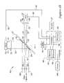
- FIG. 1is a diagram of the circular polarization illumination based analyzer system
- FIG. 2 ais a diagram showing edge and front views of a beam separator of the analyzer system
- FIG. 2 bshows various views of a center mirror of the beam separator
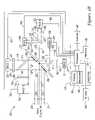
- FIG. 3is a diagram of the analyzer system of FIG. 1 having an extended detection mechanism.
- WBC measurement in a cytometermay consist of discriminating the five forms of WBCs with a counting of particles in each group.
- the five kinds of WBCs or leukocytesinclude three kinds of granulocytes—neutrophils, eosinophils and basophils, and two kinds of leukocytes without granules in their cytoplasm—lymphocytes and monocytes.
- the present systemprovides an enhancement to a forward angle light scattering/small angle light scattering approach of light scattered off the WBCs that may show a complete separation in plotted data.
- Birefringence of particlesmay provide a basis of discrimination of various kinds of particles for grouping, such as WBCs.
- polarized lightBy using polarized light, one can measure the effects that individual particles may reveal by the incident polarized light. Such effects appear useful for discriminating various particles from one another.
- Circular polarized lightmay be used in the present system to impinge particles which in turn scatter such light.
- FALS and SALS detectorshaving linear polarizers orthogonally situated relative to each other in terms of a polarization state or direction, before them, may detect such light to provide data in the form of, for instance, scattergrams, with information discriminating various kinds of particles apart from one another.
- the present systemgoes beyond a depolarization measurement approach of particles, such as WBCs, where a ninety degree angle scattering of light that is polarized naturally with a measurement being the extent that the light is unpolarized or depolarized.
- a distinguishing characteristic of the present systemis a use of circularly polarized light to impinge a target, having orthogonal polarizers between the target and detectors for detecting small angle (i.e., of about or less than 20 degrees) and forward angle light (i.e. of about or less than 5 degrees), respectively, scattered from the target.
- Small angle scattered light, forward angle scattered light, and unscattered lightmay be defined in terms of angles having magnitudes other than those illustratively stated herein.
- FIG. 1shows a particle discrimination system 10 .
- a light source 11may emanate a light 12 through a collimating lens 13 .
- Light 12may proceed through a linear polarizer 14 .
- Polarized light 15may proceed through a quarter-wave plate 16 which converts the linearly polarized light 15 into circularly polarized light 17 .
- light source 11may emanate linearly polarized 15 or circularly polarized light 17 , thereby eliminating polarizer 14 or polarizers 14 and 16 , respectively.
- Light 17may proceed through a lens 18 to be focused on particles 19 in a channel or receptacle 21 of a card 22 . Some of the light 17 may impinge particles 19 and be scattered into light 23 and 24 . Other light 17 might not be scattered.
- Light 24may be the result of small angel light scattering by the particles in the channel.
- Light 23may be the result of forward angle light scattering by the particles.
- the angle range of scattering of light 23may be between about one and five degrees relative to the optical axis 20 of the system 10 .
- the angle range of scattering of light 24may be between about five and twenty degrees relative to the optical axis 20 .
- the light 17which is effectively non-scattered, may be light between zero and about one degree relative to the optical axis. These ranges may be predetermined and adjusted as desired to obtain certain performance from system 10 .
- Light 17 , 23 and 24may be collimated by a lens 25 .
- Light 17may proceed approximately along the optical axis 20 to a mirror 26 situated in a structure 27 .
- the mirror 26may have a generally flat reflective surface which is situated at about a 45 degree angle counterclockwise relative to the optical axis 20 .
- the light 17may be reflected by mirror 26 to a zero detector 31 .
- Detector 31may indicate an amplitude or intensity of light 17 impinging it at about the same time of the impingement.
- Light 23may proceed through a circular opening or hole 28 of structure 27 .
- the opening 28may be concentric relative to the location of mirror 26 .
- Light 23 of a scatter angle greater than one degreemay miss the mirror 26 as it proceeds through opening 28 .
- Light 23may go through a linear polarizer 34 to become linearly polarized light 36 , which may be detected by a FALS detector 32 . Similar to detector 31 , detector 32 may indicate the amplitude or intensity of the light 36 impinging it at about the same time of the impingement.
- the opening 28may be small enough to prevent light coming through scattered at an angle not greater than about five degrees. This angle may be adjusted as desired by varying the hole diameter.
- Structure 27may be a beam separator having a reflective surface 29 .
- Reflective surface 29may annular and concentric to the opening or hole 28 .
- Surface 29may extend from the outer edge of the opening 28 and extend outward a certain dimension resulting in the shape of a ring or circular band on the surface of structure 27 facing the incoming light 24 .
- the width of the ring or annular band of reflective surface 29may be such as to reflect light 24 having a scatter angle between about five and twenty degrees relative to the optical axis 20 .
- the dimensions of surface 29may be changed to reflect light of other scatter angles.
- Reflective surface 29may be positioned at about 45 degrees in a clockwise direction relative to the optical axis 20 .
- Surface 29may reflect the light 24 through a linear polarizer 35 to become linearly polarized light 37 , which may be detected by a SALS detector 33 .
- SALS detector 33may indicate the amplitude or intensity of light 37 impinging it at about the same time of the impingement.
- Linear polarizer 14may polarize light 12 in one direction, and the quarter-wave plate 16 may provide counter-clockwise or clockwise polarization of light 15 from a perspective of facing the cartridge 22 on the light source 11 side.
- the channel 21may have a flow direction in the up, down, in or out, relative to the drawing sheet surface of FIG. 1 .
- Polarizer 34may polarize light 23 in one direction or another while facing the FALS detector 32 .
- Polarizer 35may polarize light 24 in another direction or so, while facing the SALS detector 33 .
- the polarization directions or states of the linear polarizers 34 and 35may be approximately orthogonal relative to each other.
- the output signals 41 , 42 and 43 of detectors 31 , 32 and 33may go to a processor 38 for converting signals into data about particles 19 in the channel 21 of card 22 .
- Various particles 19may be discriminated from one another.
- Data, calculations and graphs, such as scattergrams,may be provided to display 39 .
- the displayed itemsmay be printed out by a printer 44 . Also, these items may be saved in a memory 45 and/or sent out to various destinations (outside 47 ) external to system 10 .
- the processor 38may receive information from the outside 47 to assist in processing the data provided by signals 41 , 42 and 43 .
- a keyboard 46may provide an interface for a user to analyze data about particles 19 , provide desired formats of processed data, and communicate both ways with the outside 47 , such as the internet.
- a computer 48may be used for providing the processor 38 , memory 45 , keyboard 46 , display 39 , and more.
- FIG. 2 ashows an edge view and a face view of structure 27 .
- Reflective disk surface 29 with an opening or hole 28 in the center of surface 29 and structure 27is shown.
- the light rays 17 , 23 and 24are shown even though the light rays and structure 27 are rotated 45 degrees clockwise to be aligned with the face view of structure 27 for illustrative purposes.
- the outside diameter of opening 28may be about 4 to 5 millimeters.
- the outside diameter of the reflective diskmay be about 8 to 10 millimeters. These dimensions may vary and depend on the placement of the various components such as the source 11 , lenses 13 , 18 , and 25 , polarizers 14 , 16 , 34 and 35 , flow channel 21 , and detectors 31 , 32 and 33 . The dimensions may also depend on focal lengths of the lenses. Other factors such as resolution, channel 21 size, design and layout of system 10 components may affect the dimensions.
- FIG. 2 bshows various views of mirror 26 .
- the reflective surface of mirror 26may be approximately perpendicular to the reflective surface 29 on structure 27 .
- the top view of mirror 26is an edge view like that shown in FIG. 2 a .
- the reflective surface of mirror 26may face down towards the lower left part of the drawing sheet.
- the middle viewis a perspective of mirror 26 .
- the bottom viewis a face view of mirror 26 .
- the diameter of mirror 26may be about one millimeter. This dimension also may depend on the other dimensions and characteristics of system 10 .
- Light source 11may be a laser diode or a similar device. If light source 11 emanates linearly polarized light, then linear polarizer 14 is not needed. If light source 11 emanates circularly polarized light, then polarizers 14 and 16 are not needed.
- Polarizers 34 and 35may polarize light about 90 degrees apart from each other in direction or state, or orthogonally relative to each other.
- Polarizer 34may have a zero degree state or direction of polarization while polarizer 35 has about a ninety degree state or direction of polarization. For instance, if one polarizer polarizes in the X direction, the other polarizer may polarize in the Y direction.
- the channel 21may be illuminated with circularly polarized light 17 .
- Onemay look at the orthogonal polarization states at two of the output channels, i.e., FALS detector 32 and SALS detector 33 .
- the zero detector 31 detecting light 17 at about a zero to one degree angle relative to the system optical axis 20may have a maximum signal indication when there are no particles 19 in channel 21 , i.e., there is no disturbance of the light 17 while propagating through channel 21 .
- the flow channel 21should be polarization free in terms of its effect on light going through it. If the particles 19 in channel 21 are birefringent, then a difference of signals may be seen in detectors 32 , 33 and 31 .
- Detector 31may be regarded as one for an extinction channel having no scattered light. Detector 31 may provide counts of particles.
- the outputs of the FALS and SALS detectors 32 and 33 , respectively,may be plotted as graphs which may be regarded as scattergrams.
- the scattergramsmay include SALS versus FALS data plotting of the particles.
- the scattergrams of particlessuch as white blood cells (WBCs) may provide a count and differentiation of four groups of the WBCs. These polarized light-based scattergrams may provide a better distinction and indication of the four groups of WBCs than non-circularly polarized light illuminated WBCs.
- WBCswhite blood cells
- a linear polarization of the circularly polarized light scattered by the cell and detected for scattergramsshow the various groups of the cells being pulled further apart from one another in the scattergrams. Also, a fifth group of WBCs (basophils) may be distinguished if a number of such cells in the illuminated sample is sufficient.
- FIG. 3shows an analyzer 30 like system 10 of FIG. 1 but having an extended detector arrangement.
- some non-scattered light 17 from mirror 26may proceed through a light splitter 51 and a linear polarizer 52 .
- a polarized light 53may go to a zero 1 detector 31 which outputs an electrical signal 41 representing the light 53 .
- Signal 41may go to processor 38 .
- Some light 17may be reflected by splitter 51 through a linear polarizer 54 .
- a polarized light 55may proceed to a zero 2 detector 56 which outputs an electrical signal 57 representing the light 55 .
- Signal 57may go to processor 38 .
- Linear polarizer 54may be orthogonal relative to linear polarizer 52 , in terms of polarizing.
- Processor 38may compare and/or analyze signals 41 and 57 of the unscattered light 53 and 55 , respectively, which can have linear polarizations orthogonal to each other, and determine birefringent effects, if any.
- Light 53 and 55may be utilized for calibration and/or compensation of the system 30 analyzer.
- forward angle scattered light 23may proceed through hole 28 to a splitter 61 . Some of the light 23 may proceed through splitter 61 and a linear polarizer 34 . From polarizer 34 , polarized light 36 may go to a FALS 1 detector 32 . An electrical signal 42 representing polarized light 36 may go from detector 32 to processor 38 . Some of the light 23 may be reflected by splitter 61 through a linear polarizer 62 . From polarizer 62 , a polarized light 63 may go to a FALS 2 detector 64 . Linear polarizer 62 may be orthogonal relative to linear polarizer 34 , in terms of polarizing.
- polarizer 34may or may not be orthogonal to polarizer 52 , in terms of polarizing.
- An electrical signal 65 representing light signal 63may go from detector 64 to processor 38 .
- Processor 38may compare and/or analyzer signals 42 and 65 and determine birefringent effects on light 23 , such as non-symmetrical birefringence affecting forward angle scattered light 23 from channel 21 .
- Light 36 and 63may be utilized for calibration and/or compensation purposes of the system 30 analyzer.
- small angle scattered light 24may be reflected by surface 29 to a splitter 71 .
- Some of the light 24may proceed through splitter 71 to a linear polarizer 35 .
- a polarized light 37may proceed to a SALS 1 detector 33 .
- An electrical signal 43 representing the linearly polarized light 37may go from detector 33 to processor 38 .
- Some light 24may be reflected by splitter 71 to a linear polarizer 72 .
- a polarized light 73may go to a SALS 2 detector 74 .
- An electrical signal 75 representing light 73may go from detector 74 to processor 38 .
- linear polarizer 72may be orthogonal relative to polarizer 35 , and polarizer 35 may be orthogonal to polarizer 34 . In some designs, polarizer 35 might not be orthogonal to polarizer 34 , in terms of polarization.
- Processor 38may compare and/or analyzer signals 43 and 75 and determine birefringent effects on light 24 , such as non-symmetrical birefringence affecting the small angle scattered light from channel 21 .
- Light 37 and 73may be utilized for calibration and/or compensation purposes of the system 30 analyzer.
- Processor 38may process signals 41 , 57 , 42 , 65 , 43 and 75 to establish data about particles 19 in channel 21 , such as groups of various sized, shaped, textured, and so forth, particles, including counts. An example is differentiating the various kinds or groups of white blood cells.
- Processor 38 computation and analysismay be performed with information from the outside 47 . Also, information may be sent by processor 38 to the outside 47 for further analysis and study.
Landscapes
- Chemical & Material Sciences (AREA)
- Physics & Mathematics (AREA)
- Health & Medical Sciences (AREA)
- Life Sciences & Earth Sciences (AREA)
- Analytical Chemistry (AREA)
- Biochemistry (AREA)
- General Health & Medical Sciences (AREA)
- General Physics & Mathematics (AREA)
- Immunology (AREA)
- Pathology (AREA)
- Dispersion Chemistry (AREA)
- Investigating Or Analysing Materials By Optical Means (AREA)
Abstract
Description
This application is a continuation-in-part of U.S. patent application Ser. No. 11/306,508 filed Dec. 30, 2005, which is a continuation-in-part of U.S. patent application Ser. No. 10/950,898, filed Sep. 27, 2004 now U.S. Pat. No. 7,130,046. U.S. patent application Ser. No. 10/950,898, filed Sep. 27, 2004, is hereby incorporated by reference. U.S. patent application Ser. No. 11/306,508, filed Dec. 30, 2005, is hereby incorporated by reference.
The present invention pertains to particle detection and particularly to discriminating particles from one another into various groups. More particularly, the invention pertains to scattered light used to discriminate these particles.
The invention relates to U.S. patent application Ser. No. 11/380,878, filed on Apr. 28, 2006, which is hereby incorporated by reference. The invention relates to U.S. Pat. No. 5,837,547, issued on Nov. 17, 1998, which is hereby incorporated by reference. The invention relates to U.S. Pat. No. 5,017,497, issued May 21, 1991, which is hereby incorporated by reference.
The invention is a system that uses polarized light to discriminate particles from one another.
Discrimination of various kinds of particles with light is a technique useful for analyses of such things as white blood cells (WBCs). For an illustrative example, WBC measurement in a cytometer may consist of discriminating the five forms of WBCs with a counting of particles in each group. The five kinds of WBCs or leukocytes include three kinds of granulocytes—neutrophils, eosinophils and basophils, and two kinds of leukocytes without granules in their cytoplasm—lymphocytes and monocytes. The present system provides an enhancement to a forward angle light scattering/small angle light scattering approach of light scattered off the WBCs that may show a complete separation in plotted data.
Birefringence of particles may provide a basis of discrimination of various kinds of particles for grouping, such as WBCs. By using polarized light, one can measure the effects that individual particles may reveal by the incident polarized light. Such effects appear useful for discriminating various particles from one another. Circular polarized light may be used in the present system to impinge particles which in turn scatter such light. FALS and SALS detectors, having linear polarizers orthogonally situated relative to each other in terms of a polarization state or direction, before them, may detect such light to provide data in the form of, for instance, scattergrams, with information discriminating various kinds of particles apart from one another.
The present system goes beyond a depolarization measurement approach of particles, such as WBCs, where a ninety degree angle scattering of light that is polarized naturally with a measurement being the extent that the light is unpolarized or depolarized. A distinguishing characteristic of the present system is a use of circularly polarized light to impinge a target, having orthogonal polarizers between the target and detectors for detecting small angle (i.e., of about or less than 20 degrees) and forward angle light (i.e. of about or less than 5 degrees), respectively, scattered from the target. Small angle scattered light, forward angle scattered light, and unscattered light may be defined in terms of angles having magnitudes other than those illustratively stated herein.
Light17,23 and24 may be collimated by alens 25.Light 17 may proceed approximately along theoptical axis 20 to amirror 26 situated in astructure 27. Themirror 26 may have a generally flat reflective surface which is situated at about a 45 degree angle counterclockwise relative to theoptical axis 20. Thelight 17 may be reflected bymirror 26 to azero detector 31.Detector 31 may indicate an amplitude or intensity oflight 17 impinging it at about the same time of the impingement.
Light23 may proceed through a circular opening orhole 28 ofstructure 27. The opening28 may be concentric relative to the location ofmirror 26. Light23 of a scatter angle greater than one degree may miss themirror 26 as it proceeds through opening28.Light 23 may go through alinear polarizer 34 to become linearly polarizedlight 36, which may be detected by aFALS detector 32. Similar todetector 31,detector 32 may indicate the amplitude or intensity of thelight 36 impinging it at about the same time of the impingement. The opening28 may be small enough to prevent light coming through scattered at an angle not greater than about five degrees. This angle may be adjusted as desired by varying the hole diameter.
The output signals41,42 and43 ofdetectors processor 38 for converting signals into data aboutparticles 19 in thechannel 21 ofcard 22.Various particles 19 may be discriminated from one another. Data, calculations and graphs, such as scattergrams, may be provided to display39. The displayed items may be printed out by aprinter 44. Also, these items may be saved in amemory 45 and/or sent out to various destinations (outside47) external tosystem 10. Theprocessor 38 may receive information from the outside47 to assist in processing the data provided bysignals keyboard 46 may provide an interface for a user to analyze data aboutparticles 19, provide desired formats of processed data, and communicate both ways with the outside47, such as the internet. Acomputer 48 may be used for providing theprocessor 38,memory 45,keyboard 46,display 39, and more.
The outside diameter of opening28 may be about 4 to 5 millimeters. The outside diameter of the reflective disk may be about 8 to 10 millimeters. These dimensions may vary and depend on the placement of the various components such as thesource 11,lenses polarizers flow channel 21, anddetectors channel 21 size, design and layout ofsystem 10 components may affect the dimensions.
Polarizers34 and35 may polarize light about 90 degrees apart from each other in direction or state, or orthogonally relative to each other.Polarizer 34 may have a zero degree state or direction of polarization whilepolarizer 35 has about a ninety degree state or direction of polarization. For instance, if one polarizer polarizes in the X direction, the other polarizer may polarize in the Y direction.
Effectively, thechannel 21 may be illuminated with circularly polarizedlight 17. One may look at the orthogonal polarization states at two of the output channels, i.e.,FALS detector 32 andSALS detector 33. The zerodetector 31 detectinglight 17 at about a zero to one degree angle relative to the systemoptical axis 20 may have a maximum signal indication when there are noparticles 19 inchannel 21, i.e., there is no disturbance of the light17 while propagating throughchannel 21. Theflow channel 21 should be polarization free in terms of its effect on light going through it. If theparticles 19 inchannel 21 are birefringent, then a difference of signals may be seen indetectors Detector 31 may be regarded as one for an extinction channel having no scattered light.Detector 31 may provide counts of particles. The outputs of the FALS andSALS detectors
A similar arrangement may be implemented in the FALS and SALS detection mechanisms. For instance, forward angle scattered light23 may proceed throughhole 28 to a splitter61. Some of the light23 may proceed through splitter61 and alinear polarizer 34. Frompolarizer 34,polarized light 36 may go to aFALS 1detector 32. Anelectrical signal 42 representingpolarized light 36 may go fromdetector 32 toprocessor 38. Some of the light23 may be reflected by splitter61 through alinear polarizer 62. Frompolarizer 62, apolarized light 63 may go to aFALS 2detector 64.Linear polarizer 62 may be orthogonal relative tolinear polarizer 34, in terms of polarizing. Depending on the system design,polarizer 34 may or may not be orthogonal to polarizer52, in terms of polarizing. Anelectrical signal 65 representinglight signal 63 may go fromdetector 64 toprocessor 38.Processor 38 may compare and/or analyzer signals42 and65 and determine birefringent effects onlight 23, such as non-symmetrical birefringence affecting forward angle scattered light23 fromchannel 21.Light system 30 analyzer.
In another instance, small angle scattered light24 may be reflected bysurface 29 to asplitter 71. Some of the light24 may proceed throughsplitter 71 to alinear polarizer 35. Frompolarizer 35, apolarized light 37 may proceed to aSALS 1detector 33. Anelectrical signal 43 representing the linearlypolarized light 37 may go fromdetector 33 toprocessor 38. Some light24 may be reflected bysplitter 71 to alinear polarizer 72. Frompolarizer 72, apolarized light 73 may go to aSALS 2detector 74. Anelectrical signal 75 representinglight 73 may go fromdetector 74 toprocessor 38. In terms of polarizing,linear polarizer 72 may be orthogonal relative to polarizer35, andpolarizer 35 may be orthogonal topolarizer 34. In some designs,polarizer 35 might not be orthogonal to polarizer34, in terms of polarization.Processor 38 may compare and/or analyzer signals43 and75 and determine birefringent effects onlight 24, such as non-symmetrical birefringence affecting the small angle scattered light fromchannel 21.Light system 30 analyzer.
In the present specification, some of the matter may be of a hypothetical or prophetic nature although stated in another manner or tense.
Although the invention has been described with respect to at least one illustrative example, many variations and modifications will become apparent to those skilled in the art upon reading the present specification. It is therefore the intention that the appended claims be interpreted as broadly as possible in view of the prior art to include all such variations and modifications.
Claims (23)
1. A polarization based analyzer system comprising:
a light source;
a first polarizer situated at an output of the light source;
a channel;
a first optical mechanism for focusing light from the polarizer to the channel;
a second optical mechanism for collimating light from the channel;
a structure for directing a first light from the second optical mechanism in a first direction and a second light from the second optical mechanism in a second direction;
a first detector for detecting the first light;
a second detector for detecting second light;
a second polarizer situated between the structure and the first detector; and
a third polarizer situated between the structure and the second detector.
2. The system ofclaim 1 , wherein:
the light source is for emanating linearly polarized light;
the first polarizer is a circular polarizer;
the second polarizer is a first linear polarizer; and
the third polarizer is a second linear polarizer.
3. The system ofclaim 2 , wherein a polarization state of the second linear polarizer is approximately orthogonal to a polarization state of the second linear polarizer.
4. The system ofclaim 3 , wherein:
the first light comprises forward angle scattered light; and
the second light comprises small angle scattered light.
5. The system ofclaim 4 , further comprising:
a computer connected to the first and second detectors; and
wherein:
the forward angle scattered light is some of the first light scattered by particles in the channel;
the small angle scattered light is some of the second light scattered by particles in the channel;
the computer processes data from the first and second detectors into small angle scatter light versus forward angle scatter light graphs; and
the graphs provide groupings of the particles according to at least one feature that distinguish particles from one another.
6. The system ofclaim 4 , wherein:
the structure comprises a first portion, a second portion and a third portion;
wherein:
the first portion is transmissive;
the second portion is reflective; and
the third portion is reflective;
the first portion is for transmitting the first light; and
the second portion is for reflecting the second light; and
the third portion is for reflecting a third light in a third direction.
7. The system ofclaim 1 , wherein the channel is of a cytometer.
8. A method for discriminating particles, comprising:
projecting circularly polarized light through a receptacle for particles;
collimating the light that has been projected through the receptacle;
separating the light into small angle scattered light and forward angle scattered light;
linearly polarizing the forward angle scattered light;
linearly polarizing the small angle scattered light orthogonally relative to the polarized forward angle scattered light; and
analyzing the polarized forward angle scattered light and the polarized small angle scattered light to discriminate particles that being in the receptacle.
9. The method ofclaim 8 , further comprising:
converting the polarized forward angle scattered light into a first type of electronic signals;
converting the polarized small angle scattered light into a second type of electronic signals; and
processing the first and second types of electronic signals into data representing various particles that being in the receptacle.
10. The method ofclaim 8 , wherein the receptacle is a flow channel of a cytometer.
11. A circularly polarized illumination-based analyzer comprising:
a circularly polarized light source;
a first light splitter;
a channel situated between the light source and the first light splitter; and
a first linear polarizer proximate to the light splitter;
a second linear polarizer proximate to the first light splitter and having a polarization direction approximately orthogonal to a polarization direction of the first linear polarizer;
a first detector proximate to the first linear polarizer;
a second detector proximate to the second linear polarizer;
the first light splitter for separating light from the channel into small angle scattered light, forward angle scattered light, and unscattered light;
the first linear polarizer for polarizing forward angle scattered light; and
the second linear polarizer is for polarizing small angle scattered light.
12. The analyzer ofclaim 11 , further comprising:
a third detector proximate to the channel; and
wherein the third detector is for detecting unscattered light.
13. The analyzer ofclaim 11 , further comprising:
a second light splitter situated between the first light splitter and the first polarizer;
a third detector proximate to the second light splitter;
a third linear polarizer situated between the second light splitter and the third detector;
a third light splitter situated between the first light splitter and the second linear polarizer;
a fourth detector proximate to the third light splitter; and
a fourth linear polarizer situated between the third light splitter and the fourth detector; and
wherein:
the third linear polarizer is orthogonal relative to the first linear polarizer; and
the fourth linear polarizer is orthogonal relative to the second linear polarizer.
14. A polarization based analyzer system comprising:
a light source;
a first polarizer situated at an output of the light source;
a channel;
a first optical mechanism for focusing light from the polarizer to the channel;
a second optical mechanism for collimating light from the channel;
a structure for directing a first light from the second optical mechanism in a first direction and a second light from the second optical mechanism in a second direction;
a first detector for detecting the first light;
a second detector for detecting second light;
a second polarizer situated between the structure and the first detector; and
a third polarizer situated between the structure and the second detector; and
wherein:
the light source is for emanating linearly polarized light;
the first polarizer is a circular polarizer;
the second polarizer is a first linear polarizer;
the third polarizer is a second linear polarizer;
a polarization state of the second linear polarizer is approximately orthogonal to a polarization state of the second linear polarizer;
the first light comprises forward angle scattered light;
the second light comprises small angle scattered light;
the structure comprises a first portion, a second portion and a third portion;
the first portion is transmissive;
the second portion is reflective;
the third portion is reflective;
the first portion is for transmitting the first light;
the second portion is for reflecting the second light; and
the third portion is for reflecting a third light in a third direction.
15. The system ofclaim 14 , further comprising:
a third detector for detecting the third light; and
wherein the third light is unscattered light.
16. The system ofclaim 14 , wherein:
the second portion is a ring-like band having borders that are different sized concentric circles;
the first portion is situated within the smaller concentric circle; and
the third portion is situated within the first portion.
17. A polarization based analyzer system comprising:
a light source;
a first polarizer situated at an output of the light source;
a channel;
a first optical mechanism for focusing light from the polarizer to the channel;
a second optical mechanism for collimating light from the channel;
a structure for directing a first light from the second optical mechanism in a first direction and a second light from the second optical mechanism in a second direction;
a first detector for detecting the first light;
a second detector for detecting second light;
a second polarizer situated between the structure and the first detector; and
a third polarizer situated between the structure and the second detector; and
wherein the channel is of a cytometer.
18. A method for discriminating particles, comprising:
projecting circularly polarized light through a receptacle for particles;
collimating the light that has been projected through the receptacle;
separating the light into small angle scattered light and forward angle scattered light;
linearly polarizing the forward angle scattered light;
linearly polarizing the small angle scattered light orthogonally relative to the polarized forward angle scattered light;
analyzing the polarized forward angle scattered light and the polarized small angle scattered light to discriminate particles that being in the receptacle;
converting the polarized forward angle scattered light into a first type of electronic signals;
converting the polarized small angle scattered light into a second type of electronic signals; and
processing the first and second types of electronic signals into data representing various particles that being in the receptacle.
19. The method ofclaim 18 , further comprising:
plotting the data representing the signals into plots; and
analyzing the plots to classify the particles into several groups.
20. A method for discriminating particles, comprising:
projecting circularly polarized light through a receptacle for particles;
collimating the light that has been projected through the receptacle;
separating the light into small angle scattered light and forward angle scattered light;
linearly polarizing the forward angle scattered light;
linearly polarizing the small angle scattered light orthogonally relative to the polarized forward angle scattered light; and
analyzing the polarized forward angle scattered light and the polarized small angle scattered light to discriminate particles that being in the receptacle; and
wherein the receptacle is a flow channel of a cytometer.
21. A circularly polarized illumination-based analyzer comprising:
a circularly polarized light source;
a first light splitter;
a channel situated between the light source and the first light splitter; and
a first linear polarizer proximate to the light splitter;
a second linear polarizer proximate to the first light splitter and having a polarization direction approximately orthogonal to a polarization direction of the first linear polarizer;
a first detector proximate to the first linear polarizer; and
a second detector proximate to the second linear polarizer; and
wherein:
the first light splitter is for separating light from the channel into small angle scattered light, forward angle scattered light, and unscattered light;
the first linear polarizer is for polarizing forward angle scattered light; and
the second linear polarizer is for polarizing small angle scattered light; and
further comprising:
a second light splitter situated between the first light splitter and the first polarizer;
a third detector proximate to the second light splitter;
a third linear polarizer situated between the second light splitter and the third detector;
a third light splitter situated between the first light splitter and the second linear polarizer;
a fourth detector proximate to the third light splitter; and
a fourth linear polarizer situated between the third light splitter and the fourth detector; and
wherein:
the third linear polarizer is orthogonal relative to the first linear polarizer; and
the fourth linear polarizer is orthogonal relative to the second linear polarizer.
22. The analyzer ofclaim 21 , further comprising:
a fifth detector proximate to the first light splitter;
a fifth linear polarizer situated between the fifth detector and the first light splitter;
a fourth light splitter situated between the fifth linear polarizer and the first detector;
a sixth detector proximate to the fourth light splitter; and
a sixth linear polarizer situated between the sixth detector and the fourth light splitter; and
wherein:
the fifth detector is for detecting unscattered light;
the sixth detector is for detecting unscattered light; and
the sixth linear polarizer is orthogonal relative to the fifth linear polarizer.
23. The analyzer ofclaim 22 , further comprising:
a processor connected to the first, second, third, fourth, fifth and sixth detectors; and
the processor processes signals from the first, second, third, fourth, fifth and sixth detectors into data for discriminating particles in the channel.
Priority Applications (2)
| Application Number | Priority Date | Filing Date | Title |
|---|---|---|---|
| US11/554,878US7630075B2 (en) | 2004-09-27 | 2006-10-31 | Circular polarization illumination based analyzer system |
| PCT/US2007/083004WO2008055157A2 (en) | 2006-10-31 | 2007-10-30 | Circular polarization illumination based analyzer system |
Applications Claiming Priority (3)
| Application Number | Priority Date | Filing Date | Title |
|---|---|---|---|
| US10/950,898US7130046B2 (en) | 2004-09-27 | 2004-09-27 | Data frame selection for cytometer analysis |
| US11/306,508US20060263888A1 (en) | 2000-06-02 | 2005-12-30 | Differential white blood count on a disposable card |
| US11/554,878US7630075B2 (en) | 2004-09-27 | 2006-10-31 | Circular polarization illumination based analyzer system |
Related Parent Applications (2)
| Application Number | Title | Priority Date | Filing Date |
|---|---|---|---|
| US10/950,898Continuation-In-PartUS7130046B2 (en) | 2000-06-02 | 2004-09-27 | Data frame selection for cytometer analysis |
| US11/306,508Continuation-In-PartUS20060263888A1 (en) | 2000-06-02 | 2005-12-30 | Differential white blood count on a disposable card |
Publications (2)
| Publication Number | Publication Date |
|---|---|
| US20070058252A1 US20070058252A1 (en) | 2007-03-15 |
| US7630075B2true US7630075B2 (en) | 2009-12-08 |
Family
ID=39204975
Family Applications (1)
| Application Number | Title | Priority Date | Filing Date |
|---|---|---|---|
| US11/554,878Active2025-12-29US7630075B2 (en) | 2004-09-27 | 2006-10-31 | Circular polarization illumination based analyzer system |
Country Status (2)
| Country | Link |
|---|---|
| US (1) | US7630075B2 (en) |
| WO (1) | WO2008055157A2 (en) |
Cited By (2)
| Publication number | Priority date | Publication date | Assignee | Title |
|---|---|---|---|---|
| US20090059227A1 (en)* | 2007-09-04 | 2009-03-05 | James Plant | Method and system for the polarmetric analysis of scattering media utilising polarization difference sensing (pds) |
| US20120327413A1 (en)* | 2011-06-22 | 2012-12-27 | Borwick Robert L | Chip-scale optics module for optical interrogators |
Families Citing this family (5)
| Publication number | Priority date | Publication date | Assignee | Title |
|---|---|---|---|---|
| JP6196502B2 (en)* | 2013-08-30 | 2017-09-13 | シスメックス株式会社 | Sample analysis method and sample analyzer |
| GB201509926D0 (en)* | 2015-06-08 | 2015-07-22 | Univ Hertfordshire Higher Education Corp | Crystalline particle detection |
| KR101658874B1 (en)* | 2015-08-03 | 2016-09-22 | 부경대학교 산학협력단 | Apparatus for discriminating bacteria types using optical scattering patterns |
| EP3371591A4 (en)* | 2015-11-02 | 2018-11-14 | Chiranjit Deka | Light scatter based apparatus and methods for hematology analysis using only three detectors |
| EP4162254A4 (en) | 2020-06-03 | 2024-06-05 | Kinetic River Corp. | CONFIGURABLE PARTICLE ANALYZER DEVICES AND METHODS |
Citations (128)
| Publication number | Priority date | Publication date | Assignee | Title |
|---|---|---|---|---|
| US3822095A (en) | 1972-08-14 | 1974-07-02 | Block Engineering | System for differentiating particles |
| US3928094A (en) | 1975-01-16 | 1975-12-23 | Fairchild Camera Instr Co | Method of aligning a wafer beneath a mask and system therefor and wafer having a unique alignment pattern |
| US3976862A (en) | 1975-03-18 | 1976-08-24 | Block Engineering, Inc. | Flow stream processor |
| US4284412A (en) | 1979-07-13 | 1981-08-18 | Ortho Diagnostics, Inc. | Method and apparatus for automated identification and enumeration of specified blood cell subclasses |
| US4478077A (en) | 1982-09-30 | 1984-10-23 | Honeywell Inc. | Flow sensor |
| US4478076A (en) | 1982-09-30 | 1984-10-23 | Honeywell Inc. | Flow sensor |
| US4501144A (en) | 1982-09-30 | 1985-02-26 | Honeywell Inc. | Flow sensor |
| JPS6082865A (en) | 1983-10-12 | 1985-05-11 | Toshiba Corp | Automatic chemical analysis apparatus |
| JPS6166974U (en) | 1984-10-08 | 1986-05-08 | ||
| US4599000A (en) | 1982-02-19 | 1986-07-08 | Canon Kabushiki Kaisha | Position detection signal processing apparatus |
| US4651564A (en) | 1982-09-30 | 1987-03-24 | Honeywell Inc. | Semiconductor device |
| US4683159A (en) | 1982-09-30 | 1987-07-28 | Honeywell Inc. | Semiconductor device structure and processing |
| US4695034A (en) | 1984-11-27 | 1987-09-22 | Stec Inc. | Fluid control device |
| US4704033A (en) | 1986-03-06 | 1987-11-03 | Micronix Corporation | Multiple wavelength linear zone plate alignment apparatus and method |
| US4745279A (en) | 1986-01-02 | 1988-05-17 | American Hospital Supply Corporation | Hematocrit measuring apparatus |
| US4818263A (en) | 1987-06-11 | 1989-04-04 | Tektronix, Inc. | Method and apparatus for precisely positioning microlenses on optical fibers |
| US4874949A (en) | 1987-09-14 | 1989-10-17 | Vanderbilt University | Method of measuring lung vascular function and transcapillary transport by the use of nonradioactive markers |
| US4911616A (en) | 1988-01-19 | 1990-03-27 | Laumann Jr Carl W | Micro miniature implantable pump |
| US4932989A (en) | 1989-04-05 | 1990-06-12 | At&T Bell Laboratories | Method and apparatus for fabricating microlenses on optical fibers |
| US4957363A (en)* | 1987-07-03 | 1990-09-18 | Hitachi, Ltd. | Apparatus for measuring characteristics of particles in fluid by detecting light scattered at the particles |
| US4980292A (en) | 1984-10-01 | 1990-12-25 | Baxter International Inc. | Tablet dispensing |
| US5017497A (en) | 1986-04-21 | 1991-05-21 | Sequoia-Turner Corporation | Particle discriminator and method |
| US5050429A (en) | 1990-02-22 | 1991-09-24 | Yamatake-Honeywell Co., Ltd. | Microbridge flow sensor |
| US5078581A (en) | 1989-08-07 | 1992-01-07 | International Business Machines Corporation | Cascade compressor |
| US5082242A (en) | 1989-12-27 | 1992-01-21 | Ulrich Bonne | Electronic microvalve apparatus and fabrication |
| US5085562A (en) | 1989-04-11 | 1992-02-04 | Westonbridge International Limited | Micropump having a constant output |
| US5096388A (en) | 1990-03-22 | 1992-03-17 | The Charles Stark Draper Laboratory, Inc. | Microfabricated pump |
| US5108623A (en) | 1990-11-19 | 1992-04-28 | Gould Inc. | Moving web filter assembly |
| US5129794A (en) | 1990-10-30 | 1992-07-14 | Hewlett-Packard Company | Pump apparatus |
| US5133602A (en)* | 1991-04-08 | 1992-07-28 | International Business Machines Corporation | Particle path determination system |
| US5171132A (en) | 1989-12-27 | 1992-12-15 | Seiko Epson Corporation | Two-valve thin plate micropump |
| US5176358A (en) | 1991-08-08 | 1993-01-05 | Honeywell Inc. | Microstructure gas valve control |
| EP0269076B1 (en) | 1986-11-27 | 1993-01-13 | Nokia (Deutschland) GmbH | Positioning device |
| US5185641A (en) | 1990-11-03 | 1993-02-09 | Horiba, Ltd. | Apparatus for simultaneously measuring large and small particle size distribution |
| US5194909A (en) | 1990-12-04 | 1993-03-16 | Tycko Daniel H | Apparatus and method for measuring volume and hemoglobin concentration of red blood cells |
| US5219278A (en) | 1989-11-10 | 1993-06-15 | Westonbridge International, Ltd. | Micropump with improved priming |
| US5224843A (en) | 1989-06-14 | 1993-07-06 | Westonbridge International Ltd. | Two valve micropump with improved outlet |
| WO1993016384A1 (en) | 1992-02-07 | 1993-08-19 | Abbott Laboratories | Method for accurately enumerating and sensitively qualifying heterogeneous cell populations in cytolytic processing conditions |
| US5244537A (en) | 1989-12-27 | 1993-09-14 | Honeywell, Inc. | Fabrication of an electronic microvalve apparatus |
| US5441597A (en) | 1992-12-01 | 1995-08-15 | Honeywell Inc. | Microstructure gas valve control forming method |
| US5452878A (en) | 1991-06-18 | 1995-09-26 | Danfoss A/S | Miniature actuating device |
| US5457526A (en) | 1992-08-10 | 1995-10-10 | Toa Medical Electronics Co., Ltd. | Apparatus for analyzing particles in fluid samples |
| WO1995027199A1 (en) | 1994-03-31 | 1995-10-12 | Nils Magnus Hjelm | Chromatography system and methodology |
| US5475370A (en)* | 1992-10-20 | 1995-12-12 | Robotic Vision Systems, Inc. | System for detecting ice or snow on surface which specularly reflects light |
| US5510267A (en) | 1989-05-15 | 1996-04-23 | Abbott Laboratories | Flow cytometry lytic agent and method enabling 5-part leukocyte differential count |
| US5528045A (en) | 1995-04-06 | 1996-06-18 | Becton Dickinson And Company | Particle analyzer with spatially split wavelength filter |
| US5570193A (en) | 1992-07-02 | 1996-10-29 | Indigo N.V. | Concentration detector for colored toner |
| US5601080A (en) | 1994-12-28 | 1997-02-11 | Coretech Medical Technologies Corporation | Spectrophotometric blood analysis |
| US5616501A (en) | 1993-05-14 | 1997-04-01 | Coulter Corporation | Reticulocyte analyzing method and apparatus utilizing light scatter techniques |
| US5633724A (en) | 1995-08-29 | 1997-05-27 | Hewlett-Packard Company | Evanescent scanning of biochemical array |
| US5683159A (en) | 1997-01-03 | 1997-11-04 | Johnson; Greg P. | Hardware mounting rail |
| US5717631A (en) | 1995-07-21 | 1998-02-10 | Carnegie Mellon University | Microelectromechanical structure and process of making same |
| US5716852A (en) | 1996-03-29 | 1998-02-10 | University Of Washington | Microfabricated diffusion-based chemical sensor |
| US5719399A (en)* | 1995-12-18 | 1998-02-17 | The Research Foundation Of City College Of New York | Imaging and characterization of tissue based upon the preservation of polarized light transmitted therethrough |
| US5726751A (en) | 1995-09-27 | 1998-03-10 | University Of Washington | Silicon microchannel optical flow cytometer |
| JPH1073528A (en) | 1996-08-30 | 1998-03-17 | Toa Medical Electronics Co Ltd | Flow cytometer equipped with imaging function |
| US5757476A (en) | 1995-12-19 | 1998-05-26 | Toa Medical Electronics Co., Ltd. | Analyzer for analyzing particle components in urine with flow cytometry |
| US5760900A (en) | 1989-03-18 | 1998-06-02 | Canon Kabushiki Kaisha | Method and apparatus for optically measuring specimen |
| US5793485A (en) | 1995-03-20 | 1998-08-11 | Sandia Corporation | Resonant-cavity apparatus for cytometry or particle analysis |
| US5799030A (en) | 1996-07-26 | 1998-08-25 | Honeywell Inc. | Semiconductor device with a laser and a photodetector in a common container |
| US5822170A (en) | 1997-10-09 | 1998-10-13 | Honeywell Inc. | Hydrophobic coating for reducing humidity effect in electrostatic actuators |
| US5837547A (en) | 1995-12-27 | 1998-11-17 | Caribbean Microparticles Corporation | Flow cytometer calibration method |
| US5836750A (en) | 1997-10-09 | 1998-11-17 | Honeywell Inc. | Electrostatically actuated mesopump having a plurality of elementary cells |
| US5839807A (en) | 1995-11-09 | 1998-11-24 | C.R.F. Societa Consortile Per Azioni | Device with micro-filters for selecting colors and images |
| US5863502A (en) | 1996-01-24 | 1999-01-26 | Sarnoff Corporation | Parallel reaction cassette and associated devices |
| US5880474A (en) | 1997-08-29 | 1999-03-09 | Becton Dickinson And Company | Multi-illumination-source flow particle analyzer with inter-location emissions crosstalk cancelation |
| US5893722A (en) | 1996-06-28 | 1999-04-13 | Honeywell Inc. | Fabrication of vertical cavity surface emitting laser with current confinement |
| US5901939A (en) | 1997-10-09 | 1999-05-11 | Honeywell Inc. | Buckled actuator with enhanced restoring force |
| US5922210A (en) | 1995-06-16 | 1999-07-13 | University Of Washington | Tangential flow planar microfabricated fluid filter and method of using thereof |
| US5932100A (en) | 1995-06-16 | 1999-08-03 | University Of Washington | Microfabricated differential extraction device and method |
| US5948684A (en) | 1997-03-31 | 1999-09-07 | University Of Washington | Simultaneous analyte determination and reference balancing in reference T-sensor devices |
| US5971158A (en) | 1996-06-14 | 1999-10-26 | University Of Washington | Absorption-enhanced differential extraction device |
| US5974867A (en) | 1997-06-13 | 1999-11-02 | University Of Washington | Method for determining concentration of a laminar sample stream |
| WO1999060397A1 (en) | 1998-05-18 | 1999-11-25 | University Of Washington | Liquid analysis cartridge |
| US6007775A (en) | 1997-09-26 | 1999-12-28 | University Of Washington | Multiple analyte diffusion based chemical sensor |
| JP2000056228A (en) | 1998-08-04 | 2000-02-25 | Carl Zeiss Jena Gmbh | System for wavelength-dependent detection used in laser scanning microscope and image recording method |
| US6032689A (en) | 1998-10-30 | 2000-03-07 | Industrial Technology Research Institute | Integrated flow controller module |
| US6054335A (en) | 1997-12-12 | 2000-04-25 | Xerox Corporation | Fabrication of scanning III-V compound light emitters integrated with Si-based actuators |
| US6067157A (en) | 1998-10-09 | 2000-05-23 | University Of Washington | Dual large angle light scattering detection |
| US6082185A (en) | 1997-07-25 | 2000-07-04 | Research International, Inc. | Disposable fluidic circuit cards |
| US6084670A (en)* | 1997-03-11 | 2000-07-04 | Nihon Kohden Corporation | Particle analyzer and composite lens formed by integrally joining plural lens elements of different focal points |
| US6091197A (en) | 1998-06-12 | 2000-07-18 | Xerox Corporation | Full color tunable resonant cavity organic light emitting diode |
| US6091537A (en) | 1998-12-11 | 2000-07-18 | Xerox Corporation | Electro-actuated microlens assemblies |
| US6094293A (en) | 1998-07-23 | 2000-07-25 | Mitsubishi Denki Kabushiki Kaisha | Optical switching apparatus for use in an optical communication system |
| US6097859A (en) | 1998-02-12 | 2000-08-01 | The Regents Of The University Of California | Multi-wavelength cross-connect optical switch |
| US6097485A (en) | 1999-03-08 | 2000-08-01 | Integrated Waveguides, Inc. | Microchip optical transport technology for use in a personal flow cytometer |
| US6106245A (en) | 1997-10-09 | 2000-08-22 | Honeywell | Low cost, high pumping rate electrostatically actuated mesopump |
| US6109889A (en) | 1995-12-13 | 2000-08-29 | Hahn-Schickard-Gesellschaft Fur Angewandte Forschung E.V. | Fluid pump |
| US6116756A (en) | 1997-12-12 | 2000-09-12 | Xerox Corporation | Monolithic scanning light emitting devices |
| US6124663A (en) | 1996-12-16 | 2000-09-26 | The Boeing Company | Fiber optic connector having a microelectromechanical positioning apparatus and an associated fabrication method |
| US6139800A (en) | 1997-06-23 | 2000-10-31 | Luminex Corporation | Interlaced lasers for multiple fluorescence measurement |
| US6179586B1 (en) | 1999-09-15 | 2001-01-30 | Honeywell International Inc. | Dual diaphragm, single chamber mesopump |
| US6184607B1 (en) | 1998-12-29 | 2001-02-06 | Honeywell International Inc. | Driving strategy for non-parallel arrays of electrostatic actuators sharing a common electrode |
| WO2001009598A1 (en) | 1999-07-28 | 2001-02-08 | University Of Washington | Fluidic interconnect, interconnect manifold and microfluidic devices for internal delivery of gases and application of vacuum |
| US6215221B1 (en) | 1998-12-29 | 2001-04-10 | Honeywell International Inc. | Electrostatic/pneumatic actuators for active surfaces |
| US6237619B1 (en) | 1996-10-03 | 2001-05-29 | Westonbridge International Limited | Micro-machined device for fluids and method of manufacture |
| US6240944B1 (en) | 1999-09-23 | 2001-06-05 | Honeywell International Inc. | Addressable valve arrays for proportional pressure or flow control |
| US6249341B1 (en) | 1999-01-25 | 2001-06-19 | Amnis Corporation | Imaging and analyzing parameters of small moving objects such as cells |
| US6281975B1 (en) | 2000-03-07 | 2001-08-28 | Eldex Laboratories, Inc. | Capillary flow cell with bulbous ends |
| US6320656B1 (en) | 2000-02-18 | 2001-11-20 | Idexx Laboratories, Inc. | High numerical aperture flow cytometer and method of using same |
| EP0694784B1 (en) | 1994-07-28 | 2002-02-27 | Hitachi, Ltd. | Liquid sampling apparatus |
| US6370407B1 (en)* | 1999-07-27 | 2002-04-09 | Tecmed, Incorporated | System for improving the sensitivity and stability of optical polarimetric measurements |
| DE10122321A1 (en) | 2000-05-09 | 2002-04-11 | Busch Dieter & Co Prueftech | Alignment of two machine parts, especially axles, is determined using an opto-electronic measurement instrument provided with two separately controlled devices for emitting a laser beam and with one laser light receiver |
| US6382228B1 (en) | 2000-08-02 | 2002-05-07 | Honeywell International Inc. | Fluid driving system for flow cytometry |
| WO2002010714A3 (en) | 2000-08-02 | 2003-01-30 | Honeywell Int Inc | Optical detection system for flow cytometry |
| US20030057968A1 (en) | 2001-09-26 | 2003-03-27 | Wang Da Yu | Liquid property sensor |
| US6597438B1 (en) | 2000-08-02 | 2003-07-22 | Honeywell International Inc. | Portable flow cytometry |
| US20030142291A1 (en) | 2000-08-02 | 2003-07-31 | Aravind Padmanabhan | Portable scattering and fluorescence cytometer |
| EP1359419A1 (en) | 2002-05-01 | 2003-11-05 | Lifescan, Inc. | Device and method for analyte concentration determination |
| US20040065143A1 (en) | 2002-10-03 | 2004-04-08 | Husher Frederick K. | Apparatus and method for analyzing a liquid in a capillary tube of a hematology instrument |
| US6721051B2 (en)* | 2000-09-20 | 2004-04-13 | Synergetic Technologies, Inc. | Non-intrusive method and apparatus for characterizing particles based on scattering matrix elements measurements using elliptically polarized radiation |
| US20040109386A1 (en) | 2002-11-18 | 2004-06-10 | Gold Kenneth S. | Particle analyzer with specimen tube in-line mixer and fluid detector |
| WO2004059316A1 (en) | 2002-12-17 | 2004-07-15 | The Regents Of The University Of Michigan | Device for the determination of blood clotting by capacitance or resistance |
| US20040154933A1 (en) | 2003-02-11 | 2004-08-12 | Instrumentation Laboratory Company | Polymeric membranes for use in electrochemical sensors |
| JP2004257756A (en) | 2003-02-24 | 2004-09-16 | Nippon Koden Corp | Flow cell positioning method and flow cytometer with adjustable flow cell position |
| US20040233424A1 (en) | 2003-05-21 | 2004-11-25 | National Cheng Kung University | Chip-based microfluidic particle detector with three dimensional focusing mechanisms |
| US6856391B2 (en)* | 2000-11-17 | 2005-02-15 | Garab Gyozo | Method and apparatus for determining the polarization properties of light emitted, reflected or transmitted by a material using a laser scanning microscope |
| US20050105077A1 (en) | 2000-08-02 | 2005-05-19 | Aravind Padmanabhan | Miniaturized cytometer for detecting multiple species in a sample |
| EP1001326B1 (en) | 1998-05-29 | 2005-08-31 | Fujikin Inc. | Gas supply equipment with pressure type flow rate control device |
| WO2005108963A1 (en) | 2004-05-06 | 2005-11-17 | Nanyang Technological University | Microfluidic cell sorter system |
| WO2005090983A3 (en) | 2004-02-27 | 2005-11-17 | Univ Texas | Membrane assay system including preloaded particles |
| WO2005114144A1 (en) | 2004-05-14 | 2005-12-01 | Honeywell International, Inc. | Portable sample analyzer cartridge |
| US6980294B2 (en)* | 2002-06-21 | 2005-12-27 | Olympus Corporation | Biomolecule analyzer |
| US20060066852A1 (en) | 2004-09-27 | 2006-03-30 | Fritz Bernard S | Data frame selection for cytometer analysis |
| EP1134548B1 (en) | 2000-03-10 | 2006-06-14 | HAMAR LASER INSTRUMENTS, Inc. | Laser alignment system with plural lasers for impingement on a single target |
| US7064873B2 (en)* | 1998-11-09 | 2006-06-20 | Silverbrook Research Pty Ltd | Integrated circuit |
| WO2005114142A3 (en) | 2004-05-14 | 2006-08-17 | Honeywell Int Inc | Portable sample analyzer with removable cartridge |
| WO2007000574A1 (en) | 2005-06-27 | 2007-01-04 | Ojk Consulting Limited | An optical arrangement for a flow cytometer |
- 2006
- 2006-10-31USUS11/554,878patent/US7630075B2/enactiveActive
- 2007
- 2007-10-30WOPCT/US2007/083004patent/WO2008055157A2/enactiveApplication Filing
Patent Citations (133)
| Publication number | Priority date | Publication date | Assignee | Title |
|---|---|---|---|---|
| US3822095A (en) | 1972-08-14 | 1974-07-02 | Block Engineering | System for differentiating particles |
| US3928094A (en) | 1975-01-16 | 1975-12-23 | Fairchild Camera Instr Co | Method of aligning a wafer beneath a mask and system therefor and wafer having a unique alignment pattern |
| US3976862A (en) | 1975-03-18 | 1976-08-24 | Block Engineering, Inc. | Flow stream processor |
| US4284412A (en) | 1979-07-13 | 1981-08-18 | Ortho Diagnostics, Inc. | Method and apparatus for automated identification and enumeration of specified blood cell subclasses |
| US4599000A (en) | 1982-02-19 | 1986-07-08 | Canon Kabushiki Kaisha | Position detection signal processing apparatus |
| US4651564A (en) | 1982-09-30 | 1987-03-24 | Honeywell Inc. | Semiconductor device |
| US4478077A (en) | 1982-09-30 | 1984-10-23 | Honeywell Inc. | Flow sensor |
| US4478076A (en) | 1982-09-30 | 1984-10-23 | Honeywell Inc. | Flow sensor |
| US4683159A (en) | 1982-09-30 | 1987-07-28 | Honeywell Inc. | Semiconductor device structure and processing |
| US4501144A (en) | 1982-09-30 | 1985-02-26 | Honeywell Inc. | Flow sensor |
| JPS6082865A (en) | 1983-10-12 | 1985-05-11 | Toshiba Corp | Automatic chemical analysis apparatus |
| US4980292A (en) | 1984-10-01 | 1990-12-25 | Baxter International Inc. | Tablet dispensing |
| JPS6166974U (en) | 1984-10-08 | 1986-05-08 | ||
| US4695034A (en) | 1984-11-27 | 1987-09-22 | Stec Inc. | Fluid control device |
| US4745279A (en) | 1986-01-02 | 1988-05-17 | American Hospital Supply Corporation | Hematocrit measuring apparatus |
| US4704033A (en) | 1986-03-06 | 1987-11-03 | Micronix Corporation | Multiple wavelength linear zone plate alignment apparatus and method |
| US5017497A (en) | 1986-04-21 | 1991-05-21 | Sequoia-Turner Corporation | Particle discriminator and method |
| EP0269076B1 (en) | 1986-11-27 | 1993-01-13 | Nokia (Deutschland) GmbH | Positioning device |
| US4818263A (en) | 1987-06-11 | 1989-04-04 | Tektronix, Inc. | Method and apparatus for precisely positioning microlenses on optical fibers |
| US4957363A (en)* | 1987-07-03 | 1990-09-18 | Hitachi, Ltd. | Apparatus for measuring characteristics of particles in fluid by detecting light scattered at the particles |
| US4874949A (en) | 1987-09-14 | 1989-10-17 | Vanderbilt University | Method of measuring lung vascular function and transcapillary transport by the use of nonradioactive markers |
| US4911616A (en) | 1988-01-19 | 1990-03-27 | Laumann Jr Carl W | Micro miniature implantable pump |
| US5760900A (en) | 1989-03-18 | 1998-06-02 | Canon Kabushiki Kaisha | Method and apparatus for optically measuring specimen |
| US4932989A (en) | 1989-04-05 | 1990-06-12 | At&T Bell Laboratories | Method and apparatus for fabricating microlenses on optical fibers |
| US5085562A (en) | 1989-04-11 | 1992-02-04 | Westonbridge International Limited | Micropump having a constant output |
| US5510267A (en) | 1989-05-15 | 1996-04-23 | Abbott Laboratories | Flow cytometry lytic agent and method enabling 5-part leukocyte differential count |
| US5224843A (en) | 1989-06-14 | 1993-07-06 | Westonbridge International Ltd. | Two valve micropump with improved outlet |
| US5078581A (en) | 1989-08-07 | 1992-01-07 | International Business Machines Corporation | Cascade compressor |
| US5219278A (en) | 1989-11-10 | 1993-06-15 | Westonbridge International, Ltd. | Micropump with improved priming |
| US5082242A (en) | 1989-12-27 | 1992-01-21 | Ulrich Bonne | Electronic microvalve apparatus and fabrication |
| US5171132A (en) | 1989-12-27 | 1992-12-15 | Seiko Epson Corporation | Two-valve thin plate micropump |
| US5244537A (en) | 1989-12-27 | 1993-09-14 | Honeywell, Inc. | Fabrication of an electronic microvalve apparatus |
| US5050429A (en) | 1990-02-22 | 1991-09-24 | Yamatake-Honeywell Co., Ltd. | Microbridge flow sensor |
| US5096388A (en) | 1990-03-22 | 1992-03-17 | The Charles Stark Draper Laboratory, Inc. | Microfabricated pump |
| US5129794A (en) | 1990-10-30 | 1992-07-14 | Hewlett-Packard Company | Pump apparatus |
| US5185641A (en) | 1990-11-03 | 1993-02-09 | Horiba, Ltd. | Apparatus for simultaneously measuring large and small particle size distribution |
| US5108623A (en) | 1990-11-19 | 1992-04-28 | Gould Inc. | Moving web filter assembly |
| US5194909A (en) | 1990-12-04 | 1993-03-16 | Tycko Daniel H | Apparatus and method for measuring volume and hemoglobin concentration of red blood cells |
| US5133602A (en)* | 1991-04-08 | 1992-07-28 | International Business Machines Corporation | Particle path determination system |
| US5452878A (en) | 1991-06-18 | 1995-09-26 | Danfoss A/S | Miniature actuating device |
| US5323999A (en) | 1991-08-08 | 1994-06-28 | Honeywell Inc. | Microstructure gas valve control |
| US5176358A (en) | 1991-08-08 | 1993-01-05 | Honeywell Inc. | Microstructure gas valve control |
| WO1993016384A1 (en) | 1992-02-07 | 1993-08-19 | Abbott Laboratories | Method for accurately enumerating and sensitively qualifying heterogeneous cell populations in cytolytic processing conditions |
| US5570193A (en) | 1992-07-02 | 1996-10-29 | Indigo N.V. | Concentration detector for colored toner |
| US5457526A (en) | 1992-08-10 | 1995-10-10 | Toa Medical Electronics Co., Ltd. | Apparatus for analyzing particles in fluid samples |
| US5475370A (en)* | 1992-10-20 | 1995-12-12 | Robotic Vision Systems, Inc. | System for detecting ice or snow on surface which specularly reflects light |
| US5441597A (en) | 1992-12-01 | 1995-08-15 | Honeywell Inc. | Microstructure gas valve control forming method |
| US5616501A (en) | 1993-05-14 | 1997-04-01 | Coulter Corporation | Reticulocyte analyzing method and apparatus utilizing light scatter techniques |
| WO1995027199A1 (en) | 1994-03-31 | 1995-10-12 | Nils Magnus Hjelm | Chromatography system and methodology |
| EP0694784B1 (en) | 1994-07-28 | 2002-02-27 | Hitachi, Ltd. | Liquid sampling apparatus |
| US5601080A (en) | 1994-12-28 | 1997-02-11 | Coretech Medical Technologies Corporation | Spectrophotometric blood analysis |
| US5793485A (en) | 1995-03-20 | 1998-08-11 | Sandia Corporation | Resonant-cavity apparatus for cytometry or particle analysis |
| US5528045A (en) | 1995-04-06 | 1996-06-18 | Becton Dickinson And Company | Particle analyzer with spatially split wavelength filter |
| US5922210A (en) | 1995-06-16 | 1999-07-13 | University Of Washington | Tangential flow planar microfabricated fluid filter and method of using thereof |
| US5932100A (en) | 1995-06-16 | 1999-08-03 | University Of Washington | Microfabricated differential extraction device and method |
| US5717631A (en) | 1995-07-21 | 1998-02-10 | Carnegie Mellon University | Microelectromechanical structure and process of making same |
| US5970315A (en) | 1995-07-21 | 1999-10-19 | Carnegie Mellon University | Microelectromechanical structure and process of making same |
| US5633724A (en) | 1995-08-29 | 1997-05-27 | Hewlett-Packard Company | Evanescent scanning of biochemical array |
| US5726751A (en) | 1995-09-27 | 1998-03-10 | University Of Washington | Silicon microchannel optical flow cytometer |
| US5839807A (en) | 1995-11-09 | 1998-11-24 | C.R.F. Societa Consortile Per Azioni | Device with micro-filters for selecting colors and images |
| US6109889A (en) | 1995-12-13 | 2000-08-29 | Hahn-Schickard-Gesellschaft Fur Angewandte Forschung E.V. | Fluid pump |
| US5719399A (en)* | 1995-12-18 | 1998-02-17 | The Research Foundation Of City College Of New York | Imaging and characterization of tissue based upon the preservation of polarized light transmitted therethrough |
| US5757476A (en) | 1995-12-19 | 1998-05-26 | Toa Medical Electronics Co., Ltd. | Analyzer for analyzing particle components in urine with flow cytometry |
| US5837547A (en) | 1995-12-27 | 1998-11-17 | Caribbean Microparticles Corporation | Flow cytometer calibration method |
| US5863502A (en) | 1996-01-24 | 1999-01-26 | Sarnoff Corporation | Parallel reaction cassette and associated devices |
| US5972710A (en) | 1996-03-29 | 1999-10-26 | University Of Washington | Microfabricated diffusion-based chemical sensor |
| US5716852A (en) | 1996-03-29 | 1998-02-10 | University Of Washington | Microfabricated diffusion-based chemical sensor |
| US5971158A (en) | 1996-06-14 | 1999-10-26 | University Of Washington | Absorption-enhanced differential extraction device |
| US5893722A (en) | 1996-06-28 | 1999-04-13 | Honeywell Inc. | Fabrication of vertical cavity surface emitting laser with current confinement |
| US5799030A (en) | 1996-07-26 | 1998-08-25 | Honeywell Inc. | Semiconductor device with a laser and a photodetector in a common container |
| JPH1073528A (en) | 1996-08-30 | 1998-03-17 | Toa Medical Electronics Co Ltd | Flow cytometer equipped with imaging function |
| US6237619B1 (en) | 1996-10-03 | 2001-05-29 | Westonbridge International Limited | Micro-machined device for fluids and method of manufacture |
| US6124663A (en) | 1996-12-16 | 2000-09-26 | The Boeing Company | Fiber optic connector having a microelectromechanical positioning apparatus and an associated fabrication method |
| US5683159A (en) | 1997-01-03 | 1997-11-04 | Johnson; Greg P. | Hardware mounting rail |
| US6084670A (en)* | 1997-03-11 | 2000-07-04 | Nihon Kohden Corporation | Particle analyzer and composite lens formed by integrally joining plural lens elements of different focal points |
| US5948684A (en) | 1997-03-31 | 1999-09-07 | University Of Washington | Simultaneous analyte determination and reference balancing in reference T-sensor devices |
| US5974867A (en) | 1997-06-13 | 1999-11-02 | University Of Washington | Method for determining concentration of a laminar sample stream |
| US6139800A (en) | 1997-06-23 | 2000-10-31 | Luminex Corporation | Interlaced lasers for multiple fluorescence measurement |
| US6082185A (en) | 1997-07-25 | 2000-07-04 | Research International, Inc. | Disposable fluidic circuit cards |
| US5880474A (en) | 1997-08-29 | 1999-03-09 | Becton Dickinson And Company | Multi-illumination-source flow particle analyzer with inter-location emissions crosstalk cancelation |
| US6007775A (en) | 1997-09-26 | 1999-12-28 | University Of Washington | Multiple analyte diffusion based chemical sensor |
| US5901939A (en) | 1997-10-09 | 1999-05-11 | Honeywell Inc. | Buckled actuator with enhanced restoring force |
| US5836750A (en) | 1997-10-09 | 1998-11-17 | Honeywell Inc. | Electrostatically actuated mesopump having a plurality of elementary cells |
| US5822170A (en) | 1997-10-09 | 1998-10-13 | Honeywell Inc. | Hydrophobic coating for reducing humidity effect in electrostatic actuators |
| US6106245A (en) | 1997-10-09 | 2000-08-22 | Honeywell | Low cost, high pumping rate electrostatically actuated mesopump |
| US6054335A (en) | 1997-12-12 | 2000-04-25 | Xerox Corporation | Fabrication of scanning III-V compound light emitters integrated with Si-based actuators |
| US6116756A (en) | 1997-12-12 | 2000-09-12 | Xerox Corporation | Monolithic scanning light emitting devices |
| US6097859A (en) | 1998-02-12 | 2000-08-01 | The Regents Of The University Of California | Multi-wavelength cross-connect optical switch |
| WO1999060397A1 (en) | 1998-05-18 | 1999-11-25 | University Of Washington | Liquid analysis cartridge |
| EP1001326B1 (en) | 1998-05-29 | 2005-08-31 | Fujikin Inc. | Gas supply equipment with pressure type flow rate control device |
| US6091197A (en) | 1998-06-12 | 2000-07-18 | Xerox Corporation | Full color tunable resonant cavity organic light emitting diode |
| US6094293A (en) | 1998-07-23 | 2000-07-25 | Mitsubishi Denki Kabushiki Kaisha | Optical switching apparatus for use in an optical communication system |
| JP2000056228A (en) | 1998-08-04 | 2000-02-25 | Carl Zeiss Jena Gmbh | System for wavelength-dependent detection used in laser scanning microscope and image recording method |
| US6067157A (en) | 1998-10-09 | 2000-05-23 | University Of Washington | Dual large angle light scattering detection |
| US6032689A (en) | 1998-10-30 | 2000-03-07 | Industrial Technology Research Institute | Integrated flow controller module |
| US7064873B2 (en)* | 1998-11-09 | 2006-06-20 | Silverbrook Research Pty Ltd | Integrated circuit |
| US6091537A (en) | 1998-12-11 | 2000-07-18 | Xerox Corporation | Electro-actuated microlens assemblies |
| US6184607B1 (en) | 1998-12-29 | 2001-02-06 | Honeywell International Inc. | Driving strategy for non-parallel arrays of electrostatic actuators sharing a common electrode |
| US6215221B1 (en) | 1998-12-29 | 2001-04-10 | Honeywell International Inc. | Electrostatic/pneumatic actuators for active surfaces |
| US6249341B1 (en) | 1999-01-25 | 2001-06-19 | Amnis Corporation | Imaging and analyzing parameters of small moving objects such as cells |
| US6097485A (en) | 1999-03-08 | 2000-08-01 | Integrated Waveguides, Inc. | Microchip optical transport technology for use in a personal flow cytometer |
| US6370407B1 (en)* | 1999-07-27 | 2002-04-09 | Tecmed, Incorporated | System for improving the sensitivity and stability of optical polarimetric measurements |
| WO2001009598A1 (en) | 1999-07-28 | 2001-02-08 | University Of Washington | Fluidic interconnect, interconnect manifold and microfluidic devices for internal delivery of gases and application of vacuum |
| US6179586B1 (en) | 1999-09-15 | 2001-01-30 | Honeywell International Inc. | Dual diaphragm, single chamber mesopump |
| US6240944B1 (en) | 1999-09-23 | 2001-06-05 | Honeywell International Inc. | Addressable valve arrays for proportional pressure or flow control |
| US6320656B1 (en) | 2000-02-18 | 2001-11-20 | Idexx Laboratories, Inc. | High numerical aperture flow cytometer and method of using same |
| US6281975B1 (en) | 2000-03-07 | 2001-08-28 | Eldex Laboratories, Inc. | Capillary flow cell with bulbous ends |
| EP1134548B1 (en) | 2000-03-10 | 2006-06-14 | HAMAR LASER INSTRUMENTS, Inc. | Laser alignment system with plural lasers for impingement on a single target |
| DE10122321A1 (en) | 2000-05-09 | 2002-04-11 | Busch Dieter & Co Prueftech | Alignment of two machine parts, especially axles, is determined using an opto-electronic measurement instrument provided with two separately controlled devices for emitting a laser beam and with one laser light receiver |
| US6382228B1 (en) | 2000-08-02 | 2002-05-07 | Honeywell International Inc. | Fluid driving system for flow cytometry |
| US6549275B1 (en) | 2000-08-02 | 2003-04-15 | Honeywell International Inc. | Optical detection system for flow cytometry |
| US20030142291A1 (en) | 2000-08-02 | 2003-07-31 | Aravind Padmanabhan | Portable scattering and fluorescence cytometer |
| WO2002010714A3 (en) | 2000-08-02 | 2003-01-30 | Honeywell Int Inc | Optical detection system for flow cytometry |
| WO2002010713A3 (en) | 2000-08-02 | 2003-12-24 | Honeywell Int Inc | Portable flow cytometer |
| US20050105077A1 (en) | 2000-08-02 | 2005-05-19 | Aravind Padmanabhan | Miniaturized cytometer for detecting multiple species in a sample |
| US6597438B1 (en) | 2000-08-02 | 2003-07-22 | Honeywell International Inc. | Portable flow cytometry |
| US6721051B2 (en)* | 2000-09-20 | 2004-04-13 | Synergetic Technologies, Inc. | Non-intrusive method and apparatus for characterizing particles based on scattering matrix elements measurements using elliptically polarized radiation |
| US6856391B2 (en)* | 2000-11-17 | 2005-02-15 | Garab Gyozo | Method and apparatus for determining the polarization properties of light emitted, reflected or transmitted by a material using a laser scanning microscope |
| US20030057968A1 (en) | 2001-09-26 | 2003-03-27 | Wang Da Yu | Liquid property sensor |
| EP1359419A1 (en) | 2002-05-01 | 2003-11-05 | Lifescan, Inc. | Device and method for analyte concentration determination |
| US6980294B2 (en)* | 2002-06-21 | 2005-12-27 | Olympus Corporation | Biomolecule analyzer |
| US20040065143A1 (en) | 2002-10-03 | 2004-04-08 | Husher Frederick K. | Apparatus and method for analyzing a liquid in a capillary tube of a hematology instrument |
| US20040109386A1 (en) | 2002-11-18 | 2004-06-10 | Gold Kenneth S. | Particle analyzer with specimen tube in-line mixer and fluid detector |
| WO2004059316A1 (en) | 2002-12-17 | 2004-07-15 | The Regents Of The University Of Michigan | Device for the determination of blood clotting by capacitance or resistance |
| US20040154933A1 (en) | 2003-02-11 | 2004-08-12 | Instrumentation Laboratory Company | Polymeric membranes for use in electrochemical sensors |
| JP2004257756A (en) | 2003-02-24 | 2004-09-16 | Nippon Koden Corp | Flow cell positioning method and flow cytometer with adjustable flow cell position |
| US20040233424A1 (en) | 2003-05-21 | 2004-11-25 | National Cheng Kung University | Chip-based microfluidic particle detector with three dimensional focusing mechanisms |
| WO2005090983A3 (en) | 2004-02-27 | 2005-11-17 | Univ Texas | Membrane assay system including preloaded particles |
| WO2005108963A1 (en) | 2004-05-06 | 2005-11-17 | Nanyang Technological University | Microfluidic cell sorter system |
| WO2005114144A1 (en) | 2004-05-14 | 2005-12-01 | Honeywell International, Inc. | Portable sample analyzer cartridge |
| WO2005114142A3 (en) | 2004-05-14 | 2006-08-17 | Honeywell Int Inc | Portable sample analyzer with removable cartridge |
| US20060066852A1 (en) | 2004-09-27 | 2006-03-30 | Fritz Bernard S | Data frame selection for cytometer analysis |
| WO2007000574A1 (en) | 2005-06-27 | 2007-01-04 | Ojk Consulting Limited | An optical arrangement for a flow cytometer |
Non-Patent Citations (45)
| Title |
|---|
| Altendorf et al, "Results Obtained Using A Prototype Microfluidics-Based Hematology Analyzer", SPIE Biomedical Optics 97, 1997. |
| Altendorf et al., "Differential Blood Cell Counts Obtained Using A Microchannel Based Flow Cytometer", Solid State Sensors & Actuators, vol. 1, 531, 1997. |
| Altendorf et al., "Implementation Of Novel Optical Detection Methods For Clinically Important Blood Analytes Using Microfabricated Flow Structures (T-Sensors(TM) )", MicroTAS 98, Banff, Canada, Apr. 1998. |
| Altendorf et al., "Microfabrication Technology For Research And Diagnostics, Silicon Microchannel Optical Flow Cytometry", SPIE Proceedings, Biomedical Optics 96, Jan. 1996. |
| Altendorf et al., "Implementation Of Novel Optical Detection Methods For Clinically Important Blood Analytes Using Microfabricated Flow Structures (T-Sensors™ )", MicroTAS 98, Banff, Canada, Apr. 1998. |
| Cabuz et al., "Mesoscopic Sampler Based on 3D Array of Electrostatically Activated Diaphragms", The 10th Int. Conf. On Solid-State Sensors and Actuators, Transducers'99, Jun. 7-12, 1999, Sendai Japan, p. 1890-1. |
| Darling et al., "Integration Of Microelectrodes With Etched Microchannels For In-Stream Electrochemical Analysis", MicroTAS 98, Banff, Canada, Apr. 1998. |
| de Grooth et al., "Light-Scattering Polarization Measurements as a New Parameter in Flow Cytometry," Cytometry 8: pp. 539-544, 1987. |
| Fedder et al., "Laminated High-Aspect-Ratio Microstructures in a Conventional CMOS Process", Proc. Micro Electro Mechanical Systems Workshop, MEMS 96, San Diego, California, Feb. 11-15, 1996, pp. 13-18. |
| Hatch et al., "Microfluidic Approaches To Immunoassays", SPIE conference on Micromachining and Microfabrication Symposium at Santa Clara, CA, Sept. 20-22, 1999. |
| HemoCue Hb 201+, Operating Manual, pp. 1-41, prior to Dec. 2006. |
| http://www.micronics.net/hfilter.htm, pp. 1-3, downloaded Jun. 14, 2000. |
| http://www.micronics.net/mcytometry.htm, pp. 1-4, downloaded Jun. 14, 2000. |
| http://www.micronics.net/orcafluidics.htm, pp. 1-4, downloaded Jun. 14, 2000. |
| http://www.micronics.net/tsensor.htm, pp. 1-4, downloaded Jun. 14, 2000. |
| Huang et al., "Development Of A Flow Cytometry Based Miniature Chemical Fluid Analysis System Using Fluorescent Microbeads", SPIE Biomedical Optics, BIOS 97, conference proceedings, 1997. |
| Lamvik et al., Nonlabeled Secondary Antibodies Augment/Maintain the Binding of Primary, Specific Antibodies to Cell Membrande Antigens, Cytometery 45, pp. 187-193, 2001. |
| Lehman et al., "High-Frequency Modulation Characteristics of Red VCSELs", Electronics Letters, Feb. 13, 1997, vol. 33(4), pp. 298-300. Copyright 1997 IEEE. |
| Ohnstein et al., "Micromachined Silicon Microvalve", Proceedings of MEMS, 1990, IEEE Micro Electromechanical Systems, Napa Valley, California, Feb. 11-14, 1990, pp. 95-98. |
| Ost et al., "Flow Cytometric Differentiation of Erythrocytes and Leukocytes in Dilute Whole Blood by Light Scattering," Cytometry 32: pp. 191-197, 1998. |
| Roulet et al., "Fabrication of Multilayer Systems Combining Microfluidic and Microoptical Elements for Fluorescence Detection," Journal of Microelectromechanical Systems, vol. 10 No. 44, pp. 483-491, Dec. 4, 2001. |
| Salzman et al., "Cell Classification by Laser Light Scattering: Identification and Separation of Unstained Leukocytes," ACTA Cytologics, vol. 19 No. 3, pp. 374-377, Jul.-Aug. 1975. |
| Shapiro, "Practical Flow Cytometry", third edition, 1995, p. 237. |
| Strzelecka et al., "Parallel Free-Space Optical Interconnect Based on Arrays of Vertical-Cavity Lasers and Detectors with Monolithic Microlenses", Applied Optics, v. 37(14), May 10, 1998, pp. 2811-2821. Copyright 1998 Optical Society of America. |
| Terstappen et al., "Four-Parameter White Blood Cell Differential Counting Based on Light Scattering Measurements", Alan R. Liss, Inc., Cytometery 9:39-43, 1988. |
| Toshiyoshi et al., "Micromechanical Lens Scanner for Fiber Optic Switches", Proc. 3rd International Conference on Micro Opto Electro Mechanical Systems (MOEMS 99), Aug. 30-Sep. 1, 1999, Mainz, Germany, pp. 165-170. |
| Toshiyoshi et al., "Surface micromachined 2D Lens Scanner Array", Proc. IEEE?LEOS International Coference on Optical EMMS/Sheraton Kauai Resort, Kauai, Hawaii, Aug. 21-24, 2000, 3 pages. |
| Tuantranont et al., "Flip Chip Integration of Lenslet Arrays on Segmented Deformable Micromirrors", Part of the Symposium on Design, Test and Microfabrication of MEMS and MOEMS, Paris, France, Mar.-Apr. 1999, SPIE vol. 3680, 0277-786X/99, pp. 668-678. |
| Tuantranont et al., "MEMS-Controllable Microlens Array For Beam Steering and Precision Alignment in Optical Interconnect Systems", Solid-State Sensor and Actuator Workshop, Hilton Head Island, South Carolina, Jun. 4-8, 2000, pp. 101-104. |
| Weigl et al, "Microfluidic Diffusion-Based Separation And Detection", Science, vol. 283, pp. 346-347, Jan. 15, 1999. |
| Weigl et al, "Optical And Electrochemical Diffusion-Based Detection Of Analytes In Complex Samples Using Microfabricated Flow Structures (T-SensorSTM)", Micro- and nanofabn'cated electro-optical mechanical systems for biomedical and environmental applications II- SPIE vol. 3606, Jan. 25-26, 1999. |
| Weigl et al, "Silicon-Microfabricated Diffusion-Based Optical Chemical Sensor", Reprint from "Sensors & Actuators" B 38-39, 452-457, 1997I. |
| Weigl et al, "Simultaneous Self-Referencing Analyte Determination In Complex Sample Solutions Using Microfabricated Flow Structures (T-Sensors(TM))", Proceedings of MicroTAS 98, 81-4, Banff, Canada, 1998. |
| Weigl et al, "Simultaneous Self-Referencing Analyte Determination In Complex Sample Solutions Using Microfabricated Flow Structures (T-Sensors™)", Proceedings of MicroTAS 98, 81-4, Banff, Canada, 1998. |
| Weigl et al., "Diffusion-Based Optical Chemical Detection In Silicon Flow Structures", B. Weigl et al., Analytical Methods & Instrumentation, muTTAS 96 special edition, 1996. |
| Weigl et al., "Fluorescence And Absorbance Analyte Sensing In Whole Blood And Plasma Based On Diffusion Separation In Silicon-Microfabricated Flow Structures (T-Sensors(TM))", Biomedical Optics, vol. 6, No. 1, Jul. 1997. |
| Weigl et al., "Rapid Sequential Chemical Analysis Using Multiple Fluorescent Reporter Beads", muTTAS 96 Conference Proceedings, 1996. |
| Weigl et al., "Diffusion-Based Optical Chemical Detection In Silicon Flow Structures", B. Weigl et al., Analytical Methods & Instrumentation, μTTAS 96 special edition, 1996. |
| Weigl et al., "Fluorescence And Absorbance Analyte Sensing In Whole Blood And Plasma Based On Diffusion Separation In Silicon-Microfabricated Flow Structures (T-Sensors™)", Biomedical Optics, vol. 6, No. 1, Jul. 1997. |
| Weigl et al., "Rapid Sequential Chemical Analysis Using Multiple Fluorescent Reporter Beads", μTTAS 96 Conference Proceedings, 1996. |
| Weigl, "Microfluidic Diffusion Based Electrochemical Detection Using Microfabricated Flow Structures (T-Sensors(TM))", Analytical Chemistry, submitted 1999. |
| Weigl, "Whole Blood Assays Using Microfluidics-Based T-SensorSTm Technology", Medical Design Online, http://news.medicaldesignonline.com/featuresarticles/19990416-5922.html, Apr. 1999. |
| Weigl, "Microfluidic Diffusion Based Electrochemical Detection Using Microfabricated Flow Structures (T-Sensors™)", Analytical Chemistry, submitted 1999. |
| Yager et al., "Applying Microfluidic Chemical Analytical Systems To Imperfect Samples", Micro Total Analysis Systems 98, D. Harrison & A. van den Berg (ed.), Kluwer Academic Publishers, Dordrecht, 207-212, 1998. |
| Yager et al., "Design Of Microfluidic Sample Preconditioning Systems For Detection Of Biological Agents In Environmental Samples", Yager, M. et al., SPIE Proceedings, 3515, 252-259, 1998. |
Cited By (4)
| Publication number | Priority date | Publication date | Assignee | Title |
|---|---|---|---|---|
| US20090059227A1 (en)* | 2007-09-04 | 2009-03-05 | James Plant | Method and system for the polarmetric analysis of scattering media utilising polarization difference sensing (pds) |
| US7956998B2 (en)* | 2007-09-04 | 2011-06-07 | James Plant | Method and system for the polarmetric analysis of scattering media utilising polarization difference sensing (PDS) |
| US20120327413A1 (en)* | 2011-06-22 | 2012-12-27 | Borwick Robert L | Chip-scale optics module for optical interrogators |
| US8654332B2 (en)* | 2011-06-22 | 2014-02-18 | Teledyne Scientific & Imaging, Llc | Chip-scale optics module for optical interrogators |
Also Published As
| Publication number | Publication date |
|---|---|
| WO2008055157A2 (en) | 2008-05-08 |
| WO2008055157A3 (en) | 2008-06-26 |
| US20070058252A1 (en) | 2007-03-15 |
Similar Documents
| Publication | Publication Date | Title |
|---|---|---|
| US7630075B2 (en) | Circular polarization illumination based analyzer system | |
| US7113266B1 (en) | Flow cytometer for differentiating small particles in suspension | |
| US6743634B2 (en) | Method and apparatus for differentiating blood cells using back-scatter | |
| US6404493B1 (en) | Dual large angle light scattering detection | |
| US7092078B2 (en) | Flow cytometer for classifying leukocytes and method for determining detection angle range of the same | |
| US6798508B2 (en) | Fiber optic apparatus for detecting light scatter to differentiate blood cells and the like | |
| US5104221A (en) | Particle size analysis utilizing polarization intensity differential scattering | |
| US4735504A (en) | Method and apparatus for determining the volume & index of refraction of particles | |
| JP2825644B2 (en) | Particle size analysis method and apparatus | |
| JPH03505131A (en) | Particle size analysis using polarized intensity difference scattering | |
| JPH0544621B2 (en) | ||
| CN112485167A (en) | Optical system of particle analyzer | |
| EP1408321B1 (en) | Pollen sensor and method | |
| Salzman | Light scattering analysis of single cells | |
| JPH08128944A (en) | Particle sorter | |
| JPH06221989A (en) | Light-scattering fine-particle detector | |
| AU3597600A (en) | High numerical aperture flow cytometer and method of using same | |
| JP3328666B2 (en) | Optical device and bill validator | |
| CN212658587U (en) | Optical system of blood cell counter and blood cell counter | |
| CN112683740A (en) | Particle measuring device and flow cytometry | |
| SU1121602A1 (en) | Device for measuring sizes and counting concentration of aerosol particles | |
| AU2023201469A1 (en) | Crystalline Particle Detection | |
| KR0125916B1 (en) | Handheld particle analyzer | |
| JPH0384437A (en) | Particle analysis device and method | |
| Magnin | Blood cell characterization by light scattering |
Legal Events
| Date | Code | Title | Description |
|---|---|---|---|
| AS | Assignment | Owner name:HONEYWELL INTERNATIONAL INC., NEW JERSEY Free format text:ASSIGNMENT OF ASSIGNORS INTEREST;ASSIGNOR:FRITZ, BERNARD S.;REEL/FRAME:018460/0171 Effective date:20061031 | |
| STCF | Information on status: patent grant | Free format text:PATENTED CASE | |
| CC | Certificate of correction | ||
| FPAY | Fee payment | Year of fee payment:4 | |
| FPAY | Fee payment | Year of fee payment:8 | |
| MAFP | Maintenance fee payment | Free format text:PAYMENT OF MAINTENANCE FEE, 12TH YEAR, LARGE ENTITY (ORIGINAL EVENT CODE: M1553); ENTITY STATUS OF PATENT OWNER: LARGE ENTITY Year of fee payment:12 |