US7628932B2 - Wet etch suitable for creating square cuts in si - Google Patents
Wet etch suitable for creating square cuts in siDownload PDFInfo
- Publication number
- US7628932B2 US7628932B2US11/445,718US44571806AUS7628932B2US 7628932 B2US7628932 B2US 7628932B2US 44571806 AUS44571806 AUS 44571806AUS 7628932 B2US7628932 B2US 7628932B2
- Authority
- US
- United States
- Prior art keywords
- single crystal
- crystal silicon
- trench
- silicon
- contacting
- Prior art date
- Legal status (The legal status is an assumption and is not a legal conclusion. Google has not performed a legal analysis and makes no representation as to the accuracy of the status listed.)
- Expired - Fee Related
Links
- 229910021421monocrystalline siliconInorganic materials0.000claimsabstractdescription106
- XUIMIQQOPSSXEZ-UHFFFAOYSA-NSiliconChemical compound[Si]XUIMIQQOPSSXEZ-UHFFFAOYSA-N0.000claimsabstractdescription73
- 229910052710siliconInorganic materials0.000claimsabstractdescription66
- 239000010703siliconSubstances0.000claimsabstractdescription66
- KRHYYFGTRYWZRS-UHFFFAOYSA-MFluoride anionChemical compound[F-]KRHYYFGTRYWZRS-UHFFFAOYSA-M0.000claimsabstractdescription58
- 238000000034methodMethods0.000claimsabstractdescription55
- 238000005530etchingMethods0.000claimsabstractdescription18
- MHAJPDPJQMAIIY-UHFFFAOYSA-NHydrogen peroxideChemical compoundOOMHAJPDPJQMAIIY-UHFFFAOYSA-N0.000claimsdescription32
- KRHYYFGTRYWZRS-UHFFFAOYSA-NFluoraneChemical compoundFKRHYYFGTRYWZRS-UHFFFAOYSA-N0.000claimsdescription25
- VYPSYNLAJGMNEJ-UHFFFAOYSA-NSilicium dioxideChemical compoundO=[Si]=OVYPSYNLAJGMNEJ-UHFFFAOYSA-N0.000claimsdescription15
- VEXZGXHMUGYJMC-UHFFFAOYSA-NHydrochloric acidChemical compoundClVEXZGXHMUGYJMC-UHFFFAOYSA-N0.000claimsdescription14
- NBIIXXVUZAFLBC-UHFFFAOYSA-NPhosphoric acidChemical compoundOP(O)(O)=ONBIIXXVUZAFLBC-UHFFFAOYSA-N0.000claimsdescription14
- LDDQLRUQCUTJBB-UHFFFAOYSA-Nammonium fluorideChemical compound[NH4+].[F-]LDDQLRUQCUTJBB-UHFFFAOYSA-N0.000claimsdescription14
- 150000007522mineralic acidsChemical class0.000claimsdescription14
- XLYOFNOQVPJJNP-UHFFFAOYSA-NwaterChemical compoundOXLYOFNOQVPJJNP-UHFFFAOYSA-N0.000claimsdescription14
- 239000007800oxidant agentSubstances0.000claimsdescription13
- VHUUQVKOLVNVRT-UHFFFAOYSA-NAmmonium hydroxideChemical compound[NH4+].[OH-]VHUUQVKOLVNVRT-UHFFFAOYSA-N0.000claimsdescription11
- DDFHBQSCUXNBSA-UHFFFAOYSA-N5-(5-carboxythiophen-2-yl)thiophene-2-carboxylic acidChemical compoundS1C(C(=O)O)=CC=C1C1=CC=C(C(O)=O)S1DDFHBQSCUXNBSA-UHFFFAOYSA-N0.000claimsdescription10
- 239000000463materialSubstances0.000claimsdescription10
- GRYLNZFGIOXLOG-UHFFFAOYSA-NNitric acidChemical compoundO[N+]([O-])=OGRYLNZFGIOXLOG-UHFFFAOYSA-N0.000claimsdescription8
- 229910052581Si3N4Inorganic materials0.000claimsdescription8
- QAOWNCQODCNURD-UHFFFAOYSA-NSulfuric acidChemical compoundOS(O)(=O)=OQAOWNCQODCNURD-UHFFFAOYSA-N0.000claimsdescription8
- 239000008367deionised waterSubstances0.000claimsdescription8
- 229910021641deionized waterInorganic materials0.000claimsdescription8
- 229910017604nitric acidInorganic materials0.000claimsdescription8
- 239000000377silicon dioxideSubstances0.000claimsdescription7
- HQVNEWCFYHHQES-UHFFFAOYSA-Nsilicon nitrideChemical compoundN12[Si]34N5[Si]62N3[Si]51N64HQVNEWCFYHHQES-UHFFFAOYSA-N0.000claimsdescription7
- 235000012239silicon dioxideNutrition0.000claimsdescription6
- CBENFWSGALASAD-UHFFFAOYSA-NOzoneChemical compound[O-][O+]=OCBENFWSGALASAD-UHFFFAOYSA-N0.000claimsdescription5
- BVKZGUZCCUSVTD-UHFFFAOYSA-Ncarbonic acidChemical compoundOC(O)=OBVKZGUZCCUSVTD-UHFFFAOYSA-N0.000claimsdescription5
- MOVBJUGHBJJKOW-UHFFFAOYSA-Nmethyl 2-amino-5-methoxybenzoateChemical compoundCOC(=O)C1=CC(OC)=CC=C1NMOVBJUGHBJJKOW-UHFFFAOYSA-N0.000claimsdescription5
- 238000000059patterningMethods0.000claimsdescription5
- 239000002253acidSubstances0.000claimsdescription4
- 239000000908ammonium hydroxideSubstances0.000claimsdescription4
- 229910000147aluminium phosphateInorganic materials0.000claimsdescription3
- 230000001590oxidative effectEffects0.000claimsdescription2
- QGZKDVFQNNGYKY-UHFFFAOYSA-OAmmoniumChemical compound[NH4+]QGZKDVFQNNGYKY-UHFFFAOYSA-O0.000claims3
- 229910000040hydrogen fluorideInorganic materials0.000claims2
- 229910003944H3 PO4Inorganic materials0.000claims1
- 239000012808vapor phaseSubstances0.000claims1
- 239000000758substrateSubstances0.000abstractdescription21
- 235000012431wafersNutrition0.000description34
- 239000000203mixtureSubstances0.000description30
- 238000004519manufacturing processMethods0.000description16
- 239000004065semiconductorSubstances0.000description16
- WGTYBPLFGIVFAS-UHFFFAOYSA-Mtetramethylammonium hydroxideChemical compound[OH-].C[N+](C)(C)CWGTYBPLFGIVFAS-UHFFFAOYSA-M0.000description16
- 230000008569processEffects0.000description9
- QPJSUIGXIBEQAC-UHFFFAOYSA-Nn-(2,4-dichloro-5-propan-2-yloxyphenyl)acetamideChemical compoundCC(C)OC1=CC(NC(C)=O)=C(Cl)C=C1ClQPJSUIGXIBEQAC-UHFFFAOYSA-N0.000description7
- KWYUFKZDYYNOTN-UHFFFAOYSA-MPotassium hydroxideChemical compound[OH-].[K+]KWYUFKZDYYNOTN-UHFFFAOYSA-M0.000description6
- 239000013078crystalSubstances0.000description6
- 150000004767nitridesChemical class0.000description6
- 238000012545processingMethods0.000description6
- 229910001868waterInorganic materials0.000description6
- QTBSBXVTEAMEQO-UHFFFAOYSA-NAcetic acidChemical compoundCC(O)=OQTBSBXVTEAMEQO-UHFFFAOYSA-N0.000description5
- 238000007254oxidation reactionMethods0.000description5
- 230000000873masking effectEffects0.000description4
- 230000003647oxidationEffects0.000description4
- KFZMGEQAYNKOFK-UHFFFAOYSA-NIsopropanolChemical compoundCC(C)OKFZMGEQAYNKOFK-UHFFFAOYSA-N0.000description3
- 238000003917TEM imageMethods0.000description3
- 238000006243chemical reactionMethods0.000description3
- 238000005516engineering processMethods0.000description3
- XLYOFNOQVPJJNP-UHFFFAOYSA-MhydroxideChemical compound[OH-]XLYOFNOQVPJJNP-UHFFFAOYSA-M0.000description3
- 239000012212insulatorSubstances0.000description3
- 238000002955isolationMethods0.000description3
- QGZKDVFQNNGYKY-UHFFFAOYSA-NAmmoniaChemical compoundNQGZKDVFQNNGYKY-UHFFFAOYSA-N0.000description2
- 229910003641H2SiO3Inorganic materials0.000description2
- -1HF2 −Chemical compound0.000description2
- 238000004630atomic force microscopyMethods0.000description2
- 238000005229chemical vapour depositionMethods0.000description2
- 239000004020conductorSubstances0.000description2
- 150000002500ionsChemical class0.000description2
- 230000003287optical effectEffects0.000description2
- 229910021420polycrystalline siliconInorganic materials0.000description2
- 230000000750progressive effectEffects0.000description2
- 230000009467reductionEffects0.000description2
- 238000006722reduction reactionMethods0.000description2
- 125000006850spacer groupChemical group0.000description2
- 229910003638H2SiF6Inorganic materials0.000description1
- UFHFLCQGNIYNRP-UHFFFAOYSA-NHydrogenChemical compound[H][H]UFHFLCQGNIYNRP-UHFFFAOYSA-N0.000description1
- 150000007513acidsChemical class0.000description1
- 229910021529ammoniaInorganic materials0.000description1
- 238000013459approachMethods0.000description1
- 238000000429assemblyMethods0.000description1
- 230000000712assemblyEffects0.000description1
- 230000009286beneficial effectEffects0.000description1
- 230000015572biosynthetic processEffects0.000description1
- 239000006172buffering agentSubstances0.000description1
- 239000003990capacitorSubstances0.000description1
- 230000008859changeEffects0.000description1
- 229910052681coesiteInorganic materials0.000description1
- 238000007796conventional methodMethods0.000description1
- 229910052906cristobaliteInorganic materials0.000description1
- 230000007423decreaseEffects0.000description1
- 230000001419dependent effectEffects0.000description1
- 238000011161developmentMethods0.000description1
- 229910003460diamondInorganic materials0.000description1
- 239000010432diamondSubstances0.000description1
- 230000009881electrostatic interactionEffects0.000description1
- NBVXSUQYWXRMNV-UHFFFAOYSA-NfluoromethaneChemical compoundFCNBVXSUQYWXRMNV-UHFFFAOYSA-N0.000description1
- 229910052739hydrogenInorganic materials0.000description1
- 239000001257hydrogenSubstances0.000description1
- 150000004679hydroxidesChemical class0.000description1
- 230000010354integrationEffects0.000description1
- 238000005259measurementMethods0.000description1
- 238000004377microelectronicMethods0.000description1
- 238000005459micromachiningMethods0.000description1
- 238000012986modificationMethods0.000description1
- 230000004048modificationEffects0.000description1
- 238000004806packaging method and processMethods0.000description1
- 238000000206photolithographyMethods0.000description1
- 229920002120photoresistant polymerPolymers0.000description1
- 230000002250progressing effectEffects0.000description1
- 238000001953recrystallisationMethods0.000description1
- 238000007493shaping processMethods0.000description1
- 229910052814silicon oxideInorganic materials0.000description1
- 238000005507sprayingMethods0.000description1
- 229910052682stishoviteInorganic materials0.000description1
- 230000003746surface roughnessEffects0.000description1
- ZEFWRWWINDLIIV-UHFFFAOYSA-Ntetrafluorosilane;dihydrofluorideChemical compoundF.F.F[Si](F)(F)FZEFWRWWINDLIIV-UHFFFAOYSA-N0.000description1
- 229910052905tridymiteInorganic materials0.000description1
Images


Classifications
- H—ELECTRICITY
- H01—ELECTRIC ELEMENTS
- H01L—SEMICONDUCTOR DEVICES NOT COVERED BY CLASS H10
- H01L21/00—Processes or apparatus adapted for the manufacture or treatment of semiconductor or solid state devices or of parts thereof
- H01L21/02—Manufacture or treatment of semiconductor devices or of parts thereof
- H01L21/04—Manufacture or treatment of semiconductor devices or of parts thereof the devices having potential barriers, e.g. a PN junction, depletion layer or carrier concentration layer
- H01L21/18—Manufacture or treatment of semiconductor devices or of parts thereof the devices having potential barriers, e.g. a PN junction, depletion layer or carrier concentration layer the devices having semiconductor bodies comprising elements of Group IV of the Periodic Table or AIIIBV compounds with or without impurities, e.g. doping materials
- H01L21/30—Treatment of semiconductor bodies using processes or apparatus not provided for in groups H01L21/20 - H01L21/26
- H01L21/302—Treatment of semiconductor bodies using processes or apparatus not provided for in groups H01L21/20 - H01L21/26 to change their surface-physical characteristics or shape, e.g. etching, polishing, cutting
- H01L21/306—Chemical or electrical treatment, e.g. electrolytic etching
- B—PERFORMING OPERATIONS; TRANSPORTING
- B81—MICROSTRUCTURAL TECHNOLOGY
- B81C—PROCESSES OR APPARATUS SPECIALLY ADAPTED FOR THE MANUFACTURE OR TREATMENT OF MICROSTRUCTURAL DEVICES OR SYSTEMS
- B81C1/00—Manufacture or treatment of devices or systems in or on a substrate
- B81C1/00436—Shaping materials, i.e. techniques for structuring the substrate or the layers on the substrate
- B81C1/00555—Achieving a desired geometry, i.e. controlling etch rates, anisotropy or selectivity
- B81C1/00626—Processes for achieving a desired geometry not provided for in groups B81C1/00563 - B81C1/00619
- C—CHEMISTRY; METALLURGY
- C30—CRYSTAL GROWTH
- C30B—SINGLE-CRYSTAL GROWTH; UNIDIRECTIONAL SOLIDIFICATION OF EUTECTIC MATERIAL OR UNIDIRECTIONAL DEMIXING OF EUTECTOID MATERIAL; REFINING BY ZONE-MELTING OF MATERIAL; PRODUCTION OF A HOMOGENEOUS POLYCRYSTALLINE MATERIAL WITH DEFINED STRUCTURE; SINGLE CRYSTALS OR HOMOGENEOUS POLYCRYSTALLINE MATERIAL WITH DEFINED STRUCTURE; AFTER-TREATMENT OF SINGLE CRYSTALS OR A HOMOGENEOUS POLYCRYSTALLINE MATERIAL WITH DEFINED STRUCTURE; APPARATUS THEREFOR
- C30B29/00—Single crystals or homogeneous polycrystalline material with defined structure characterised by the material or by their shape
- C30B29/02—Elements
- C30B29/06—Silicon
- C—CHEMISTRY; METALLURGY
- C30—CRYSTAL GROWTH
- C30B—SINGLE-CRYSTAL GROWTH; UNIDIRECTIONAL SOLIDIFICATION OF EUTECTIC MATERIAL OR UNIDIRECTIONAL DEMIXING OF EUTECTOID MATERIAL; REFINING BY ZONE-MELTING OF MATERIAL; PRODUCTION OF A HOMOGENEOUS POLYCRYSTALLINE MATERIAL WITH DEFINED STRUCTURE; SINGLE CRYSTALS OR HOMOGENEOUS POLYCRYSTALLINE MATERIAL WITH DEFINED STRUCTURE; AFTER-TREATMENT OF SINGLE CRYSTALS OR A HOMOGENEOUS POLYCRYSTALLINE MATERIAL WITH DEFINED STRUCTURE; APPARATUS THEREFOR
- C30B33/00—After-treatment of single crystals or homogeneous polycrystalline material with defined structure
- C30B33/08—Etching
- C30B33/10—Etching in solutions or melts
- H—ELECTRICITY
- H01—ELECTRIC ELEMENTS
- H01L—SEMICONDUCTOR DEVICES NOT COVERED BY CLASS H10
- H01L21/00—Processes or apparatus adapted for the manufacture or treatment of semiconductor or solid state devices or of parts thereof
- H01L21/02—Manufacture or treatment of semiconductor devices or of parts thereof
- H01L21/04—Manufacture or treatment of semiconductor devices or of parts thereof the devices having potential barriers, e.g. a PN junction, depletion layer or carrier concentration layer
- H01L21/18—Manufacture or treatment of semiconductor devices or of parts thereof the devices having potential barriers, e.g. a PN junction, depletion layer or carrier concentration layer the devices having semiconductor bodies comprising elements of Group IV of the Periodic Table or AIIIBV compounds with or without impurities, e.g. doping materials
- H01L21/30—Treatment of semiconductor bodies using processes or apparatus not provided for in groups H01L21/20 - H01L21/26
- H01L21/302—Treatment of semiconductor bodies using processes or apparatus not provided for in groups H01L21/20 - H01L21/26 to change their surface-physical characteristics or shape, e.g. etching, polishing, cutting
- H01L21/306—Chemical or electrical treatment, e.g. electrolytic etching
- H01L21/30604—Chemical etching
- H01L21/30608—Anisotropic liquid etching
- B—PERFORMING OPERATIONS; TRANSPORTING
- B81—MICROSTRUCTURAL TECHNOLOGY
- B81B—MICROSTRUCTURAL DEVICES OR SYSTEMS, e.g. MICROMECHANICAL DEVICES
- B81B2203/00—Basic microelectromechanical structures
- B81B2203/03—Static structures
- B81B2203/0323—Grooves
- B81B2203/033—Trenches
- B—PERFORMING OPERATIONS; TRANSPORTING
- B81—MICROSTRUCTURAL TECHNOLOGY
- B81B—MICROSTRUCTURAL DEVICES OR SYSTEMS, e.g. MICROMECHANICAL DEVICES
- B81B2203/00—Basic microelectromechanical structures
- B81B2203/03—Static structures
- B81B2203/0323—Grooves
- B81B2203/0338—Channels
Definitions
- the present inventionrelates generally to methods for undercutting single crystal silicon using wet etchants. More particularly, the present invention relates to methods for creating square undercuts in single crystal silicon and resulting structures.
- MEMSMicro-electromechanical systems
- ICintegrated circuit fabrication
- mechanical componentsmay be fabricated using micromachining processes that are compatible with the integrated circuit fabrication processes.
- both single crystal and polycrystalline siliconare typically wet etched in mixtures of nitric acid (HNO 3 ) and hydrofluoric acid (HF).
- HNO 3nitric acid
- HFhydrofluoric acid
- the etchingis generally isotropic.
- the reactionis initiated by the HNO 3 , which forms a layer of silicon dioxide on the silicon, and the HF dissolves the silicon oxide away.
- wateris used to dilute the etchant, with acetic acid (CH 3 COOH) being a preferred buffering agent.
- the (111) planeis more densely packed than the (100) plane, and thus the etch rates of (111) orientated surfaces are expected to be lower than those with (100) orientations. Bonding orientation of the different planes also contributes to etchant selectivity to exposed planes.
- One etchant that exhibits such orientation-dependent etching propertiesconsists of a mixture of KOH and isopropyl alcohol. For example, such a mixture may etch about one hundred (100) times faster along (100) planes than along (111) planes.
- FIGS. 1A-2Bshow a silicon etch performed with different etchant solutions in both the standard silicon orientation ( FIG. 1A and FIG. 2A ) and 45° rotation ( FIG. 1B and FIG. 2B ).
- a maskis aligned along the ⁇ 110> directions.
- the ⁇ 111 ⁇ planesdefine the sidewalls which are sloped from (100) surface plane.
- the 45° rotationthe mask is aligned along the ⁇ 100> direction.
- the etchantwas dilute NH 4 OH applied at 26° C. and in FIGS.
- the etchantwas dilute TMAH applied at 26° C. While the two etchants display different selectivity, both undercut the silicon 10 and create beveled edges or chamfers 12 . The beveled edges may be undesirable for some applications and may limit the spacing of components on the integrated circuit.
- FIG. 1Ais a cross-sectional view of single crystal silicon masked along the ⁇ 110> direction and undercut with NH 4 OH applied at 26° C.
- FIG. 1Bshows of single crystal silicon masked along the ⁇ 100> direction and undercut with NH 4 OH applied at 26° C.
- FIG. 2Ais a cross-sectional view of single crystal silicon masked along the ⁇ 110> direction and undercut with dilute TMAH applied at 26° C.
- FIG. 2Bshows of single crystal silicon masked along the ⁇ 100> direction and undercut with dilute TMAH applied at 26° C.
- FIG. 3Ais a cross-sectional view of single crystal silicon masked along the ⁇ 110> direction and undercut with a buffered fluoride etch solution of the present invention applied at 23° C.
- FIG. 3Bshows single crystal silicon masked along the ⁇ 100> direction and undercut with a buffered fluoride etch solution of the present invention applied at 23° C.
- FIGS. 4A-11Dshow a single crystal silicon wafer at various stages in a fabrication process according to one embodiment of the present invention.
- FIG. 4Ais a plan view of single crystal silicon wafer according to an embodiment of the present invention.
- FIG. 4Bis a cross-sectional view of the same single crystal silicon wafer taken along line— 4 B—of FIG. 4A .
- FIG. 5Ais a plan view of single crystal silicon wafer according to an embodiment of the present invention.
- FIG. 5Bis a cross-sectional view of the same single crystal silicon wafer taken along line— 5 B—of FIG. 5A .
- FIG. 6Ais a plan view of single crystal silicon wafer according to an embodiment of the present invention.
- FIG. 6Bis a cross-sectional view of the same single crystal silicon wafer taken along line— 6 B—of FIG. 6A .
- FIG. 7Ais a plan view of single crystal silicon wafer according to an embodiment of the present invention.
- FIG. 7Bis a cross-sectional view of the same single crystal silicon wafer taken along line— 7 B—of FIG. 7A .
- FIG. 8Ais a plan view of single crystal silicon wafer according to an embodiment of the present invention.
- FIG. 8Bis a cross-sectional view of the same single crystal silicon wafer taken along line— 8 B—of FIG. 8A .
- FIG. 9Ais a plan view of single crystal silicon wafer according to an embodiment of the present invention.
- FIG. 9Bis a cross-sectional view of the same single crystal silicon wafer taken along line— 9 B—of FIG. 9A .
- FIG. 10Ais a plan view of single crystal silicon wafer according to an embodiment of the present invention.
- FIG. 10Bis a cross-sectional view of the same single crystal silicon wafer taken along line— 10 B—of FIG. 10A .
- FIG. 10Cis a cross-sectional view of the single crystal silicon wafer of FIG. 10A taken along line— 10 C—of FIG. 10A .
- FIG. 11Ais a plan view of single crystal silicon wafer according to an embodiment of the present invention.
- FIG. 11Bis a cross-sectional view of the same single crystal silicon wafer taken along line— 11 B—of FIG. 11A .
- FIG. 11Cis a cross-sectional view of the single crystal silicon wafer of FIG. 11A taken along line— 11 C—of FIG. 11A .
- FIG. 11Dis a cross-sectional view of the single crystal silicon wafer of FIG. 11A taken along line— 11 D—of FIG. 11A .
- FIGS. 12A-Eshow a progressive undercut etch of single crystal silicon using a buffered fluoride etch solution of the present invention.
- the trenchesare in the ⁇ 100> direction on (100) silicon.
- FIGS. 13A-Dshow a progressive undercut etch of single crystal silicon using a buffered fluoride etch solution of the present invention after exposure to NH 4 OH.
- the trenchesare in the ⁇ 100> direction on (100) silicon.
- FIGS. 14A-Bshow transmission electron micrographs (TEMs) of an integrated PSOI DRAM access structure.
- wafer and substrateas used in the following description include any structure having an exposed surface with which to form the integrated circuit (IC) structure of the invention.
- substrateis understood to include semiconductor wafers.
- substrateis also used to refer to semiconductor structures during processing, and may include other layers that have been fabricated thereupon. Both wafer and substrate include doped and undoped semiconductors, epitaxial semiconductor layers supported by a base semiconductor or insulator, as well as other semiconductor structures well known to those of ordinary skill in the art.
- conductoris understood to include semiconductors, and the term “insulator” is defined to include any material that is less electrically conductive than the materials referred to as conductors.
- horizontalas used in this application is defined as a plane parallel to the conventional plane or surface of a wafer or substrate, regardless of the orientation of the wafer or substrate.
- verticalrefers to a direction perpendicular to the horizontal as defined above. Prepositions, such as “on,” “side” (as in “sidewall”), “higher,” “lower,” “over” and “under” are defined with respect to the conventional plane or surface being on the top surface of the wafer or substrate, regardless of the orientation of the wafer or substrate.
- a buffered fluoride etch solutionmay be used to create square corners and lateral shelves in (100) silicon without the typical bevel experienced with hydroxide etches when the initial pattern is oriented along the ⁇ 100> direction.
- the wet etch chemistry of the present inventionmay be used to fabricate devices that have previously been prohibitively expensive, complicated and/or poor yielding.
- An embodiment of the present inventionfurther includes methods employing etchant solutions to manipulate the cavity shape of a trench underlying single crystal silicon.
- Etch chemistryis highly selective to crystal orientation, when using (100) crystal plane orientation and patterning in a ⁇ 100> direction, a cavity shape lacking beveled corners and including a lateral shelf may be achieved.
- An embodiment of the present inventionincludes a method of etching the (100) crystal silicon plane 2-3 times slower than the (110) and (111) silicon planes.
- the etch rate of (100) siliconmay be approximately 5-10,000 ⁇ /min and preferably 10-500 ⁇ /min in dilute etchants at low temperatures.
- the methodmay include exposing the silicon to a buffered fluoride etch solution of the present invention.
- the methodmay further include a simultaneous slower etch on an oxide and/or nitride relative to the (100) silicon.
- a square undercut in single crystal siliconmay be created by providing single crystal silicon including at least one trench therein, patterning the single crystal silicon in the ⁇ 100> direction and exposing the single crystal silicon to a solution including a fluoride component, an oxidizing agent and an inorganic acid.
- a lateral shelfmay be created by exposing single crystal silicon to an anisotropic etchant followed by a buffered fluoride etch solution.
- a lateral shelfmay be created by exposing single crystal silicon to a first isotropic etchant to create a trench.
- An anisotropic etchantmay be applied to undercut the silicon and a buffered fluoride etch solution may be applied to square the corners of the undercut cavity. It will be understood that the buffered fluoride etch solution, which etches silicon at different rates in different exposed planes, may be used in the trench without a first anisotropic etchant.
- An embodiment of the present inventionincludes a semiconductor device including single crystal silicon having a square undercut feature.
- the undercut featureincludes smooth surfaces.
- An embodiment of the present inventionincludes a semiconductor device including single crystal silicon having a lateral shelf.
- Etch compositions for oxidizing silicon and etching silicon dioxide to create desired structures according to the present inventionshall be generally described below. With the description as provided below, it will be readily apparent to one skilled in the art that the buffered fluoride etch compositions described herein may be used in various applications. In other words, the buffered fluoride etch compositions may be used whenever silicon etch is being performed and wherein square undercuts or lateral shelves are desired. For example, the present invention may be used in the formation of isolation structures for use in the fabrication of integrated circuits.
- the present inventionmay be beneficial in the fabrication of transistor structures, such as pseudo-silicon-on-insulator devices (including DRAM, SRAM, Flash, imagers, PCRAM, MRAM, CAM, etc.), FinFets, surround gate transistors, as well as micro electronic mechanical systems (“MEMS”) and electro-optical components.
- transistor structuressuch as pseudo-silicon-on-insulator devices (including DRAM, SRAM, Flash, imagers, PCRAM, MRAM, CAM, etc.), FinFets, surround gate transistors, as well as micro electronic mechanical systems (“MEMS”) and electro-optical components.
- pseudo-silicon-on-insulator devicesincluding DRAM, SRAM, Flash, imagers, PCRAM, MRAM, CAM, etc.
- FinFetsFinFets
- surround gate transistorsas well as micro electronic mechanical systems (“MEMS”) and electro-optical components.
- MEMSmicro electronic mechanical systems
- a buffered fluoride etch composition for use in undercutting single crystal silicon to form lateral shelvesgenerally includes a fluoride component, an inorganic acid and an oxidizing agent.
- the fluoride componentmay be, without limitation, HF, HF 2 ⁇ , NH 4 F, or tetramethylammonium fluoride (TMAF).
- TMAFtetramethylammonium fluoride
- the ammonium fluoridemay be formed with a mixture of ammonium hydroxide and HF.
- the fluoride component or solutionis such that when the reaction of the etch composition with silicon forms silicon dioxide, the fluoride component or solution dissolves away the silicon dioxide formed thereby.
- the fluoride componentmay be present in the amount of 0.5-50% by weight.
- the oxidizing agent of the buffered fluoride etch compositionmay be any oxidizing agent such as, for example, hydrogen peroxide or ozone.
- One currently preferred oxidizing agentis hydrogen peroxide.
- the inorganic acid componentmay include at least one acid selected from hydrofluoric acid (HF), phosphoric acid (H 3 PO 4 ), sulfuric acid (H 2 SO 4 ), nitric acid (HNO 3 ), hydrochloric acid (HCl), carbonic acid (H 2 CO 3 ), or any other suitable inorganic acid. It is currently preferred that the inorganic acid be H 3 PO 4 or H 2 CO 3 . Inorganic acids are commercially available as concentrated solutions (X) which then typically are diluted to a desired concentration (H 2 O:X).
- HClis 37% by weight in deionized water
- HNO 3is 70% by weight in deionized water
- H 2 SO 4is 96% by weight in deionized water
- H 3 PO 4is 85% by weight in deionized water.
- Concentrations of etch compositions described hereinare given based on commercially available solutions. For example, if the etch composition has a concentration of 30% HCl, then the solution includes 30% by weight of the commercially available HCl solution.
- Hydrogen peroxide (H 2 O 2 )is also commercially available as a concentrated solution of approximately 29% by weight in deionized water.
- ammonium fluorideis also commercially available as a concentrated solution, approximately 40% by weight in deionized water. Further, one will recognize that multiple components of the solution may be provided from commercially available solutions. For example, a wet etch solution may be employed that provides both NH 4 F ( ⁇ 39.4 w %) and an inorganic acid (i.e., H 3 PO 4 ⁇ 0.6 w %) that may be used to adjust the pH of the solution.
- a wet etch solutionmay be employed that provides both NH 4 F ( ⁇ 39.4 w %) and an inorganic acid (i.e., H 3 PO 4 ⁇ 0.6 w %) that may be used to adjust the pH of the solution.
- the buffered fluoride etch solutionpreferably has a pH in the range of about 5.0 to about 9.0. More preferably, the buffered fluoride etch composition has a pH of about 7.8.
- the buffered fluoride etch compositionincludes a fluoride component in a range of about 0.5 percent to about 50 percent by weight of the buffered fluoride etch composition, an oxidizing agent in the range of about 0.5 percent to about 30 percent by weight of the buffered fluoride etch composition; and an inorganic acid in the range of about 0.1-2% by weight.
- the buffered fluoride etch compositionmay preferably include a volumetric ratio of NH 4 F:QEII:H 2 O 2 of about 4:2:3.
- the ionic strength of the buffered fluoride etch compositionis greater than one; more preferably, the ionic strength is in the range of about 5 to about 20.
- ionic strengthrefers to a measure of the average electrostatic interaction among ions in the composition which is equal to one-half the sum of the terms obtained by multiplying the molality of each ion by its valence squared.
- the redox potential of the etch compositionis in the range of about ⁇ 0.5 to about +0.7 or higher (vs. Standard Hydrogen Electrode (SHE)).
- SHEStandard Hydrogen Electrode
- the redox potentialis a measure of the effectiveness of the etch composition as an oxidizing agent, i.e., the ability of the etch composition to oxidize silicon for removal by the HF component of the etch composition.
- buffered fluoride etch solutionis particularly applicable to the use of ammonium fluoride and hydrogen peroxide but appear to be equally applicable to buffered fluoride etch compositions having other combinations of components as described above, such as when ammonium fluoride is provided by ammonium hydroxide and hydrofluoric acid.
- suitable amounts of ammonium hydroxide and hydrofluoric acidmay be mixed to provide an adequate amount of ammonium fluoride.
- ozoneis preferably present in a range of about 1 parts per million (ppm) to about 50 ppm.
- the buffered fluoride etch solutionmay exhibit an etch rate of silicon that is greater than 3 times the etch rate of an oxide being exposed to the same etch composition, i.e., the selectivity between silicon and oxide is greater than 3. More preferably, the selectivity between silicon and oxide using the etch composition is greater than 6 compared to ⁇ 100> silicon etch rate.
- the etch rate for silicon using the etch compositionis preferably greater than about 5 ⁇ /min. More preferably, the etch rate for silicon is greater than 18 ⁇ /min. Even more preferably, the etch rate for silicon is greater than 30-50 ⁇ per minute.
- the etch compositionis such that after removal of silicon using the etch composition the silicon surface has a desired surface roughness adequate for later processing.
- the roughness of the silicon surface following the etchis within the range of about 1.25 ⁇ RMS to about 1.30 ⁇ RMS.
- the silicon surfacemay desirably fall within such a range for roughness after more than 180 ⁇ of silicon is removed.
- roughnessmay be determined by Atomic Force Microscopy (AFM) which scans a surface area of about 1 ⁇ m 2 and gives an average peak-to-valley measurement across this 1 ⁇ m 2 surface area, rms.
- AFMAtomic Force Microscopy
- the high selectivity to oxide as described aboveis a high selectivity to thermal oxide.
- thermal oxidemay be formed by thermal oxidation such as with use of a wet or dry furnace oxidation.
- selectivityis also applicable to oxides formed by chemical vapor deposition (CVD), such as high density plasma oxide typically used in isolation processes, such as shallow trench isolation.
- CVDchemical vapor deposition
- any known methodmay be used to expose the silicon to the buffered fluoride etch solution.
- the siliconmay be immersed into a tank of the buffered fluoride etch solution.
- the solutionmay also be sprayed onto the wafers being etched or may be introduced for contact with the wafer in any other manner, e.g., drip, spraying, vapor, etc.
- the etching processmay be performed at a temperature in the range of about 10° C. to about 90° C.
- the etching processoccurs at a temperature between 21° C. to about 30° C. and, more preferably, between about 22° C. and 25° C.
- FIGS. 1A through 2Bshow that when NH 4 OH or TMAH is used to undercut silicon, virtually no lateral shelf is formed.
- the corners of the undercut structurehave chamfers 12 .
- FIG. 1B and FIG. 2Bshow that a silicon 10 undercut was performed in both the standard silicon orientation (i.e., patterned along the ⁇ 110> direction) and 45° rotation in (100) silicon using a buffered fluoride etch solution (10 L NH 4 F+5 L QEII+7.5 L H 2 O 2 ) at 26° C.
- the buffered fluoride etch solution used in FIGS. 3A and 3Bdemonstrates that the (100) silicon planes is the slow etching planes which allows the creation of square undercuts if the pattern is aligned along the ⁇ 100> direction.
- the (111) planeis a slow etch; thus, it was surprising to discover a wet etch with a slow plane etch in (100) silicon.
- the buffered fluoride etch solutionprovides very useful selectivity, smooth surfaces and controllable etching of (100) silicon.
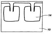
- the lateral shelf 14 and lack of beveled cornersenables the easy creation thereon of electrical devices such as FinFETs, Pseudo-SOI or RAD bowls in standard CMOS wafers which are manufactured on (100) silicon.
- the use of the buffered fluoride etch solutionalso creates concave square corners without a lateral spacer which is desirable for electronic properties in silicon fingers of sheets which have very different properties from the adjacent material having no material etched.
- the concave square corners depicted in FIG. 3Bare also useful for a discrete change in device mechanical and optical properties when fabricating MEMS.
- the concave corner in (100) siliconalso allows simple integration in CMOS devices and enables MEMS mechanical and optical structures to be integrated with CMOS processing more easily.
- FIGS. 4A-11Ddepict a partial process for creating a pseudo-SOI structure according to a method of the present invention.
- part Ashows a plan view of the structure and part B shows a cross-sectional view of the corresponding structure taken along—B—.
- FIGS. 4A and Bdepict a single crystal silicon substrate 100 .
- a silicon nitride liner 112is formed thereover.
- a masking layer 128is formed over the silicon nitride liner 112 as known in the art.
- the masking layer 128may be patterned to form at least one trench mask opening 132 .
- Conventional photolithography or other lithographic or non-lithographic methods, regardless of the presence of the masking layer 128are also contemplated.
- the silicon nitride liner 112 and single crystal silicon substrate 100are etched through the mask opening 132 to form at least one trench 116 within the single crystal silicon substrate 100 .
- the etchmay be conducted utilizing a dry anisotropic etching chemistry, with or without plasma, for example comprising ammonia and at least one fluorocarbon.
- Masking layer 128may remain or may be removed when etching into the single crystal silicon substrate 100 . While a specific method of forming trench 116 has been disclosed, it will be understood by one of skill in the art that any method of forming trench 116 may be utilized.
- a nitride layermay be deposited over the silicon nitride liner 112 and trench 116 followed by an etch which removes the nitride from the bottom 126 of the trench 116 , but creates nitride spacers 118 on the sidewalls 130 of trench 116 . Creation of the Si 3 N 4 liner may be performed by conventional techniques.
- the buffered fluoride etch solution of the present inventionmay then be applied to undercut the single crystal silicon substrate 10 .
- the buffered fluoride etch solutionmay be applied at approximately 23° C. for approximately 5 minutes, depending on the desired size of the lateral shelf 114 .
- the buffered fluoride etch solutionetches faster in a direction parallel to the single crystal silicon substrate 100 as compared with the vertical etch through the bottom 126 of the trench 116 .
- a lateral shelf 114 having a thickness of approximately 450 ⁇ to 550 ⁇may be created as shown in FIG. 7B .
- a nitride liner 120may be deposited on the bottom 126 and sidewalls 130 of the trench 116 and then the trench 116 may be filled with an oxide material 122 , for example, a spin-on-dielectric (SOD) as shown in FIGS. 8A and B.
- an oxide material 122for example, a spin-on-dielectric (SOD) as shown in FIGS. 8A and B.
- a mask 124is deposited and patterned over the silicon nitride liner 112 and oxide material 122 .
- a conventional silicon etch having some selectivity to oxidemay be performed as shown in FIGS. 9A , B and 10 A, B, C.
- An optional nitride liner 136may be deposited and an SOD fill may be preformed as shown in FIGS. 11A , B, C and D. After the SOD fill depicted in FIGS. 11A-11D , the structure 150 may be subjected to further processing to form, for example, transistors, capacitors and digit lines thereover to complete the pseudo-SOI structure.
- the structure 150includes a lateral shelf 114 having a thickness of about 500 ⁇ (+/ ⁇ 10%).
- structure 150has significantly lower leakage due to the presence of oxide material 122 underlying the silicon. (See, e.g., FIG. 11B ). It will be understood that structure 150 is not limited to being an intermediate pseudo-SOI structure. Any number of additional fabrication steps may be performed in conjunction with the present invention to create any desired device.
- FIGS. 12A-Edepict silicon oxidation and etching using a solution of NH 4 F, QEII and H 2 O 2 (provided in a ratio of 4:2:3).
- the substratewas immersed in a stagnant bath of the NH 4 F, QEII and H 2 O 2 solution at 23° C.
- FIG. 12Adepicts a trench 310 in single crystal silicon 300 with a nitride liner 320 prior to addition of the buffered fluoride etch solution of the present invention.
- the top surface 312 of the single crystal siliconrepresents the (100) plane.
- the trench 310is ⁇ 100> on the (100) plane.
- FIG. 12BAfter 16 minutes of exposure to the buffered fluoride etch solution at approximately 23° C., an undercut profile is visible having a lateral shelf 314 .
- FIG. 12BThe etch is progressing faster perpendicular to the (100) direction (i.e., perpendicular to the STI sidewall), than in the (100) direction (i.e., perpendicular to the wafer surface) as shown in FIGS. 12C , D and E after 22 min., 25 min. and 28 min. exposure, respectively.
- the width of the underlying silicon leg, or pillar, 350decreases with increased exposure to the buffered fluoride etch solution.
- FIG. 13A-Ddepicts the etch progression of single crystal silicon 400 at 0 min. ( FIG. 13A ), 3 min. ( FIG. 13B ), 6 min. ( FIG. 13C ) and 9 min. ( FIG. 13D ) exposure to the NH 4 F, QEII and H 2 O 2 solution (the buffered fluoride etch solution) after a five minute anisotropic NH 4 OH etch at 23° C. Exposure occurred using a stagnant bath.
- the top surface 412 of the single crystal siliconrepresents the (100) plane.
- the trench 410is ⁇ 100> on the (100) plane.
- the buffered fluoride etch solutionforms a shelf undercut of the silicon active area without significantly increasing the trench depth. Further, it can be seen that the silicon legs, or pillars, 450 under the single crystal silicon 400 becomes increasingly narrow as the etch progresses. Thus, it will be understood that using appropriate pattern angles in combination with etchant solutions of the present invention, devices may be manufactured having various characteristics. By manipulating the etch time and etchant combination, different undercut profiles may be achieved. For example, the buffered fluoride etch solution may be combined with hydroxides, NH 4 OH, NH 4 F, TMAH or combinations thereof.
- the inventionmay further be understood by the following non-limiting examples.
- FIGS. 14A and Bdepict two TEMs of an integrated PSOI DRAM access structure.
- the profilewas created by the combination of a TMAH (100:1) etch of 4 minutes 36 seconds at 25° C.
- a second etch using the buffered fluoride etch solution(NH 4 F, QEII and H 2 O 2 (provided in a ratio of 4:2:3) was run at 25° C. for 6 minutes.
- a conventional oxide spacerwas used for the two wet etches and removed after the cavity creation.
- the imageis shown in the ⁇ 100> direction after the access transistors and bit line were integrated along with poly-silicon plugs between the transistor gates.
Landscapes
- Engineering & Computer Science (AREA)
- Chemical & Material Sciences (AREA)
- Physics & Mathematics (AREA)
- Manufacturing & Machinery (AREA)
- Microelectronics & Electronic Packaging (AREA)
- Geometry (AREA)
- Organic Chemistry (AREA)
- Metallurgy (AREA)
- Materials Engineering (AREA)
- Crystallography & Structural Chemistry (AREA)
- Condensed Matter Physics & Semiconductors (AREA)
- Power Engineering (AREA)
- Computer Hardware Design (AREA)
- General Physics & Mathematics (AREA)
- General Chemical & Material Sciences (AREA)
- Chemical Kinetics & Catalysis (AREA)
- Weting (AREA)
- Element Separation (AREA)
- Semiconductor Memories (AREA)
- Crystals, And After-Treatments Of Crystals (AREA)
Abstract
Description
Si+2 H2O2=H2SiO3+H2O=SiO2+2 H2O (1)
Half-cell reduction/oxidation reactions:
H2O2+2 H++2e−⇄2 H2O E0′=+1.77V (2)
Sis+2 OH−⇄=Si(OH)2+2e− (3)
H2SiO3+6 HF⇄H2SiF6+3 H2O (4)
The typical selectivity between (100) silicon crystal orientation and thermal oxide is approximately 6. The (110) directional etch is approximately two and one half times higher than (100) silicon etch.
Claims (29)
Priority Applications (13)
| Application Number | Priority Date | Filing Date | Title |
|---|---|---|---|
| US11/445,718US7628932B2 (en) | 2006-06-02 | 2006-06-02 | Wet etch suitable for creating square cuts in si |
| EP07795580AEP2030225A2 (en) | 2006-06-02 | 2007-05-31 | Wet etch suitable for creating square cuts in si and resulting structures |
| CN201410209104.3ACN103956321A (en) | 2006-06-02 | 2007-05-31 | Single crystal silicon etching method and semiconductor structure obtained therefrom |
| KR1020087031282AKR101072760B1 (en) | 2006-06-02 | 2007-05-31 | Wet etch suitable for creating square cuts in si and resulting structures |
| JP2009513289AJP5278768B2 (en) | 2006-06-02 | 2007-05-31 | Method for making a right angle undercut in single crystal silicon |
| PCT/US2007/012904WO2007143072A2 (en) | 2006-06-02 | 2007-05-31 | Wet etch suitable for creating square cuts in si and resulting structures |
| CNA200780020525XACN101461040A (en) | 2006-06-02 | 2007-05-31 | Wet etch suitable for creating square cuts in Silicon and resulting structure |
| TW096119774ATWI356451B (en) | 2006-06-02 | 2007-06-01 | Wet etch suitable for creating square cuts in si a |
| US12/565,557US7973388B2 (en) | 2006-06-02 | 2009-09-23 | Semiconductor structures including square cuts in single crystal silicon |
| US13/176,416US8294246B2 (en) | 2006-06-02 | 2011-07-05 | Semiconductor structures including square cuts in single crystal silicon and method of forming same |
| US13/416,834US9040424B2 (en) | 2006-06-02 | 2012-03-09 | Methods of forming single crystal silicon structures and semiconductor device structures including single crystal silicon structures |
| US13/599,791US8450214B2 (en) | 2006-06-02 | 2012-08-30 | Methods of etching single crystal silicon |
| US14/676,338US20150206761A1 (en) | 2006-06-02 | 2015-04-01 | Methods of forming single crystal silicon structures |
Applications Claiming Priority (1)
| Application Number | Priority Date | Filing Date | Title |
|---|---|---|---|
| US11/445,718US7628932B2 (en) | 2006-06-02 | 2006-06-02 | Wet etch suitable for creating square cuts in si |
Related Child Applications (1)
| Application Number | Title | Priority Date | Filing Date |
|---|---|---|---|
| US12/565,557DivisionUS7973388B2 (en) | 2006-06-02 | 2009-09-23 | Semiconductor structures including square cuts in single crystal silicon |
Publications (2)
| Publication Number | Publication Date |
|---|---|
| US20070278183A1 US20070278183A1 (en) | 2007-12-06 |
| US7628932B2true US7628932B2 (en) | 2009-12-08 |
Family
ID=38663107
Family Applications (4)
| Application Number | Title | Priority Date | Filing Date |
|---|---|---|---|
| US11/445,718Expired - Fee RelatedUS7628932B2 (en) | 2006-06-02 | 2006-06-02 | Wet etch suitable for creating square cuts in si |
| US12/565,557ActiveUS7973388B2 (en) | 2006-06-02 | 2009-09-23 | Semiconductor structures including square cuts in single crystal silicon |
| US13/176,416ActiveUS8294246B2 (en) | 2006-06-02 | 2011-07-05 | Semiconductor structures including square cuts in single crystal silicon and method of forming same |
| US13/599,791ActiveUS8450214B2 (en) | 2006-06-02 | 2012-08-30 | Methods of etching single crystal silicon |
Family Applications After (3)
| Application Number | Title | Priority Date | Filing Date |
|---|---|---|---|
| US12/565,557ActiveUS7973388B2 (en) | 2006-06-02 | 2009-09-23 | Semiconductor structures including square cuts in single crystal silicon |
| US13/176,416ActiveUS8294246B2 (en) | 2006-06-02 | 2011-07-05 | Semiconductor structures including square cuts in single crystal silicon and method of forming same |
| US13/599,791ActiveUS8450214B2 (en) | 2006-06-02 | 2012-08-30 | Methods of etching single crystal silicon |
Country Status (7)
| Country | Link |
|---|---|
| US (4) | US7628932B2 (en) |
| EP (1) | EP2030225A2 (en) |
| JP (1) | JP5278768B2 (en) |
| KR (1) | KR101072760B1 (en) |
| CN (2) | CN101461040A (en) |
| TW (1) | TWI356451B (en) |
| WO (1) | WO2007143072A2 (en) |
Cited By (9)
| Publication number | Priority date | Publication date | Assignee | Title |
|---|---|---|---|---|
| US20080188051A1 (en)* | 2007-02-07 | 2008-08-07 | Micron Technology, Inc. | Methods of forming one or more covered voids in a semiconductor substrate, methods of forming field effect transistors, methods of forming semiconductor-on-insulator substrates, methods of forming a span comprising silicon dioxide, methods of cooling semiconductor devices, methods of forming electromagnetic radiation emitters and conduits, methods of forming imager systems, methods of forming nanofluidic channels, fluorimetry methods, and integrated circuitry |
| US20090026522A1 (en)* | 2007-07-09 | 2009-01-29 | Venkatesan Ananthan | Semiconductor device comprising transistor structures and methods for forming same |
| US20090236666A1 (en)* | 2006-08-18 | 2009-09-24 | Micron Technology, Inc. | Integrated Circuitry |
| US20090275208A1 (en)* | 2008-05-02 | 2009-11-05 | Nishant Sinha | Compositions of Matter, and Methods of Removing Silicon Dioxide |
| US20100065941A1 (en)* | 2006-06-02 | 2010-03-18 | Micron Technology, Inc. | Intermediate semiconductor structures |
| US20100109120A1 (en)* | 2006-06-02 | 2010-05-06 | Micron Technology, Inc. | Single crystal silicon structures |
| US8450214B2 (en) | 2006-06-02 | 2013-05-28 | Micron Technology, Inc. | Methods of etching single crystal silicon |
| WO2014133760A1 (en) | 2013-02-26 | 2014-09-04 | Micron Technology, Inc. | Photonic device structure and method of manufacture |
| US20210375668A1 (en)* | 2020-05-28 | 2021-12-02 | Imec Vzw | Method for producing an undercut in a 300 mm silicon-on-insulator platform |
Families Citing this family (43)
| Publication number | Priority date | Publication date | Assignee | Title |
|---|---|---|---|---|
| JP2007251095A (en)* | 2006-03-20 | 2007-09-27 | Toshiba Corp | Semiconductor manufacturing method |
| US8852851B2 (en) | 2006-07-10 | 2014-10-07 | Micron Technology, Inc. | Pitch reduction technology using alternating spacer depositions during the formation of a semiconductor device and systems including same |
| US7989307B2 (en) | 2008-05-05 | 2011-08-02 | Micron Technology, Inc. | Methods of forming isolated active areas, trenches, and conductive lines in semiconductor structures and semiconductor structures including the same |
| US10151981B2 (en)* | 2008-05-22 | 2018-12-11 | Micron Technology, Inc. | Methods of forming structures supported by semiconductor substrates |
| DE102008040597A1 (en)* | 2008-07-22 | 2010-01-28 | Robert Bosch Gmbh | Micromechanical component with back volume |
| US8247302B2 (en) | 2008-12-04 | 2012-08-21 | Micron Technology, Inc. | Methods of fabricating substrates |
| US8796155B2 (en) | 2008-12-04 | 2014-08-05 | Micron Technology, Inc. | Methods of fabricating substrates |
| US8273634B2 (en) | 2008-12-04 | 2012-09-25 | Micron Technology, Inc. | Methods of fabricating substrates |
| US8329046B2 (en)* | 2009-02-05 | 2012-12-11 | Asia Union Electronic Chemical Corporation | Methods for damage etch and texturing of silicon single crystal substrates |
| US8268543B2 (en) | 2009-03-23 | 2012-09-18 | Micron Technology, Inc. | Methods of forming patterns on substrates |
| US9330934B2 (en) | 2009-05-18 | 2016-05-03 | Micron Technology, Inc. | Methods of forming patterns on substrates |
| US7994062B2 (en)* | 2009-10-30 | 2011-08-09 | Sachem, Inc. | Selective silicon etch process |
| GB201005979D0 (en)* | 2010-04-09 | 2010-05-26 | Nexeon Ltd | A method of fabricating structured particles composed of silicon or a silicon-based material and their use in lithium rechargeable batteries |
| TWI404136B (en)* | 2010-04-13 | 2013-08-01 | Univ Nat Taipei Technology | A novel fabrication method for producing undercut-etching microstructure |
| US8518788B2 (en) | 2010-08-11 | 2013-08-27 | Micron Technology, Inc. | Methods of forming a plurality of capacitors |
| US8512588B2 (en)* | 2010-08-13 | 2013-08-20 | Lawrence Livermore National Security, Llc | Method of fabricating a scalable nanoporous membrane filter |
| US8455341B2 (en) | 2010-09-02 | 2013-06-04 | Micron Technology, Inc. | Methods of forming features of integrated circuitry |
| US8575032B2 (en) | 2011-05-05 | 2013-11-05 | Micron Technology, Inc. | Methods of forming a pattern on a substrate |
| CN103035709B (en)* | 2011-09-30 | 2015-11-25 | 中国科学院微电子研究所 | Semiconductor structure and manufacturing method thereof |
| US9076680B2 (en) | 2011-10-18 | 2015-07-07 | Micron Technology, Inc. | Integrated circuitry, methods of forming capacitors, and methods of forming integrated circuitry comprising an array of capacitors and circuitry peripheral to the array |
| GB2497120A (en)* | 2011-12-01 | 2013-06-05 | Rec Wafer Norway As | Production of mono-crystalline silicon |
| US9323010B2 (en)* | 2012-01-10 | 2016-04-26 | Invensas Corporation | Structures formed using monocrystalline silicon and/or other materials for optical and other applications |
| US9177794B2 (en) | 2012-01-13 | 2015-11-03 | Micron Technology, Inc. | Methods of patterning substrates |
| US8772902B2 (en) | 2012-04-19 | 2014-07-08 | International Business Machines Corporation | Fabrication of a localized thick box with planar oxide/SOI interface on bulk silicon substrate for silicon photonics integration |
| WO2013166481A1 (en)* | 2012-05-04 | 2013-11-07 | Akrion Systems Llc | Method for consistently texturizing silicon wafers during solar cell wet chemical processing |
| US8629048B1 (en) | 2012-07-06 | 2014-01-14 | Micron Technology, Inc. | Methods of forming a pattern on a substrate |
| WO2014039034A1 (en)* | 2012-09-05 | 2014-03-13 | Commissariat A L'energie Atomique Et Aux Energies Alternatives | Method for fabricating microelectronic devices with isolation trenches partially formed under active regions |
| US9396984B2 (en)* | 2012-09-05 | 2016-07-19 | Commissariat A L'energie Atomique Et Aux Energies Alternatives | Method of producing a microelectronic device in a monocrystalline semiconductor substrate with isolation trenches partially formed under an active region |
| US9287178B2 (en) | 2012-10-01 | 2016-03-15 | Globalfoundries Inc. | Multi-gate field effect transistor (FET) including isolated fin body |
| US9006066B2 (en) | 2013-04-26 | 2015-04-14 | Globalfoundries Inc. | FinFET with active region shaped structures and channel separation |
| FR3009887B1 (en)* | 2013-08-20 | 2015-09-25 | Commissariat Energie Atomique | IMPROVED METHOD OF SEPARATION BETWEEN AN ACTIVE ZONE OF A SUBSTRATE AND ITS REAR FACE OR A PORTION OF ITS BACKFACE |
| CN103730487B (en)* | 2013-12-16 | 2017-07-18 | 启东吉莱电子有限公司 | It is a kind of to improve positive pressure-resistant controllable silicon mesa structure and its manufacturing process |
| AR101858A1 (en) | 2014-09-15 | 2017-01-18 | Dow Agrosciences Llc | PROTECTED HERBICIDE COMPOSITIONS THAT INCLUDE A PYRIDINCARBOXYL ACID HERBICIDE |
| CN105274626B (en)* | 2015-10-10 | 2017-12-01 | 浙江晶科能源有限公司 | A kind for the treatment of fluid and processing method for being used to optimize black silicon face structure |
| CN106990461B (en)* | 2016-01-20 | 2020-05-15 | 安徽中科米微电子技术有限公司 | Silicon echelle grating with right angle and vertex angle and manufacturing method thereof |
| US10325779B2 (en) | 2016-03-30 | 2019-06-18 | Tokyo Electron Limited | Colloidal silica growth inhibitor and associated method and system |
| US10515820B2 (en) | 2016-03-30 | 2019-12-24 | Tokyo Electron Limited | Process and apparatus for processing a nitride structure without silica deposition |
| CN106531683B (en)* | 2016-12-29 | 2019-05-31 | 中国科学院微电子研究所 | Semiconductor-on-insulator material substrate structure and preparation method thereof |
| DE102017217713B4 (en) | 2017-10-05 | 2022-12-01 | Fraunhofer-Gesellschaft zur Förderung der angewandten Forschung e.V. | Process for making electrical contacts on a solar cell and solar cell |
| WO2020217769A1 (en)* | 2019-04-26 | 2020-10-29 | 株式会社サイオクス | Method for producing structure, apparatus for producing structure, and intermediate structure |
| US11712766B2 (en)* | 2020-05-28 | 2023-08-01 | Toyota Motor Engineering And Manufacturing North America, Inc. | Method of fabricating a microscale canopy wick structure having enhanced capillary pressure and permeability |
| DE102021206956A1 (en)* | 2021-07-02 | 2023-01-05 | Q.ant GmbH | Method of forming free-standing microstructures on a diamond crystal and diamond crystal |
| WO2023119230A1 (en) | 2021-12-22 | 2023-06-29 | L'oreal | Coagulation pathway and nicotinamide-adenine dinucleotide pathway modulating compositions and methods of their use |
Citations (40)
| Publication number | Priority date | Publication date | Assignee | Title |
|---|---|---|---|---|
| US4531282A (en) | 1977-04-25 | 1985-07-30 | Nippon Telegraph And Telephone Public Corp. | Bipolar transistors having vertically arrayed collector-base-emitter with novel polycrystalline base electrode surrounding island emitter and method of making same |
| US4891255A (en)* | 1988-09-29 | 1990-01-02 | The United States Of America As Represented By The United States Department Of Energy | (110) Oriented silicon wafer latch accelerometer and process for forming the same |
| US5427975A (en) | 1993-05-10 | 1995-06-27 | Delco Electronics Corporation | Method of micromachining an integrated sensor on the surface of a silicon wafer |
| US5536675A (en) | 1993-12-30 | 1996-07-16 | Intel Corporation | Isolation structure formation for semiconductor circuit fabrication |
| US6100162A (en) | 1999-05-14 | 2000-08-08 | Micron Technology, Inc. | Method of forming a circuitry isolation region within a semiconductive wafer |
| US6245615B1 (en) | 1999-08-31 | 2001-06-12 | Micron Technology, Inc. | Method and apparatus on (110) surfaces of silicon structures with conduction in the <110> direction |
| US6290863B1 (en)* | 1999-07-31 | 2001-09-18 | Micron Technology, Inc. | Method and apparatus for etch of a specific subarea of a semiconductor work object |
| US6319333B1 (en) | 1996-11-12 | 2001-11-20 | Micron Technology, Inc. | Silicon-on-insulator islands |
| US20020001968A1 (en) | 1999-08-30 | 2002-01-03 | Whonchee Lee | Compositions for etching silicon with high selectivity to oxides and methods of using same |
| US6339241B1 (en) | 2000-06-23 | 2002-01-15 | International Business Machines Corporation | Structure and process for 6F2 trench capacitor DRAM cell with vertical MOSFET and 3F bitline pitch |
| US20020025636A1 (en) | 1999-10-20 | 2002-02-28 | Dong-Hyuk Ju | Field effect transitor with non-floating body and method for forming same on a bulk silicon wafer |
| US6358861B1 (en) | 1999-01-13 | 2002-03-19 | Mitsubishi Denki Kabushiki Kaisha | Manufacturing method of silicon device |
| US6465865B1 (en) | 1996-01-05 | 2002-10-15 | Micron Technology, Inc. | Isolated structure and method of fabricating such a structure on a substrate |
| US20030003759A1 (en) | 2001-06-27 | 2003-01-02 | Infineon Technologies North America Corp | Etch selectivity inversion for etching along crystallographic directions in silicon |
| US20030022505A1 (en)* | 2001-07-24 | 2003-01-30 | Luc Ouellet | Micro-fluidic devices |
| US6518112B2 (en) | 1998-01-05 | 2003-02-11 | International Business Machines Corporation | High performance, low power vertical integrated CMOS devices |
| US20030057438A1 (en) | 2001-09-24 | 2003-03-27 | Motorola, Inc. | Structure and method for fabricating semiconductor structures and devices utilizing lateral epitaxial overgrowth |
| US6602745B2 (en) | 2000-09-14 | 2003-08-05 | Infineon Technologies North America Corp. | Field effect transistor and method of fabrication |
| US20040014280A1 (en) | 2002-07-22 | 2004-01-22 | Josef Willer | Non-Volatile memory cell and fabrication method |
| US6686214B2 (en)* | 2000-12-08 | 2004-02-03 | Dalsa Semiconductor Inc. | Method of aligning a photolithographic mask to a crystal plane |
| US20040038533A1 (en) | 1999-04-09 | 2004-02-26 | Chunlin Liang | Isolated junction structure and method of manufacture |
| US6713341B2 (en)* | 2002-02-05 | 2004-03-30 | Nanya Technology Corporation | Method of forming a bottle-shaped trench in a semiconductor substrate |
| US20040067346A1 (en) | 2000-12-19 | 2004-04-08 | Hofmann Wolfgang M. J. | Multiple-level actuators and clamping devices |
| US20040118805A1 (en) | 2002-12-18 | 2004-06-24 | Hareland Scott A. | Pre-etch implantation damage for the removal of thin film layers |
| US6784076B2 (en) | 2002-04-08 | 2004-08-31 | Micron Technology, Inc. | Process for making a silicon-on-insulator ledge by implanting ions from silicon source |
| US6808994B1 (en) | 2003-06-17 | 2004-10-26 | Micron Technology, Inc. | Transistor structures and processes for forming same |
| US20040214436A1 (en) | 2000-02-07 | 2004-10-28 | Dow Daniel B. | Method of fabricating a semiconductor work object |
| US20050020091A1 (en) | 2003-07-22 | 2005-01-27 | Janos Fucsko | Wet etching method of removing silicon from a substrate and method of forming trench isolation |
| US6858903B2 (en) | 2002-11-20 | 2005-02-22 | International Business Machines Corporation | MOSFET device with in-situ doped, raised source and drain structures |
| US6881622B2 (en) | 2002-05-30 | 2005-04-19 | Taiwan Semiconductor Manufacturing Co., Ltd | Aqueous ammonium hydroxide amorphous silicon etch method for forming microelectronic capacitor structure |
| US6902962B2 (en) | 2003-04-04 | 2005-06-07 | Taiwan Semiconductor Manufacturing Company, Ltd. | Silicon-on-insulator chip with multiple crystal orientations |
| US6909147B2 (en) | 2003-05-05 | 2005-06-21 | International Business Machines Corporation | Multi-height FinFETS |
| US6927104B2 (en) | 2003-09-15 | 2005-08-09 | Chartered Semiconductor Manufacturing Ltd. | Method of forming double-gated silicon-on-insulator (SOI) transistors with corner rounding |
| US20050208727A1 (en) | 2004-03-18 | 2005-09-22 | Nanya Technology Corporation | Method of etching bottle trench and fabricating capacitor with same |
| US6960507B2 (en) | 2003-07-24 | 2005-11-01 | Samsung Electronics Co., Ltd. | Vertical double-channel silicon-on-insulator transistor and method of manufacturing the same |
| US6963114B2 (en) | 2003-12-29 | 2005-11-08 | Taiwan Semiconductor Manufacturing Company, Ltd. | SOI MOSFET with multi-sided source/drain silicide |
| US6964903B2 (en) | 1998-09-01 | 2005-11-15 | Micron Technology, Inc. | Method of fabricating a transistor on a substrate to operate as a fully depleted structure |
| US6968110B2 (en) | 2003-04-21 | 2005-11-22 | Sioptical, Inc. | CMOS-compatible integration of silicon-based optical devices with electronic devices |
| US7045407B2 (en) | 2003-12-30 | 2006-05-16 | Intel Corporation | Amorphous etch stop for the anisotropic etching of substrates |
| US20070173007A1 (en) | 2006-01-23 | 2007-07-26 | Hynix Semiconductor, Inc. | Semiconductor device and method for fabricating the same |
Family Cites Families (26)
| Publication number | Priority date | Publication date | Assignee | Title |
|---|---|---|---|---|
| US4407058A (en)* | 1981-05-22 | 1983-10-04 | International Business Machines Corporation | Method of making dense vertical FET's |
| JPH0414868A (en) | 1990-05-09 | 1992-01-20 | Hitachi Ltd | Semiconductor memory and manufacture thereof |
| KR970000533B1 (en) | 1990-12-20 | 1997-01-13 | 후지쓰 가부시끼가이샤 | Eprom with trench in thick field oxide |
| JP3919921B2 (en) | 1997-09-26 | 2007-05-30 | 三菱電機株式会社 | Semiconductor device |
| US6066869A (en) | 1997-10-06 | 2000-05-23 | Micron Technology, Inc. | Circuit and method for a folded bit line memory cell with vertical transistor and trench capacitor |
| US6528837B2 (en) | 1997-10-06 | 2003-03-04 | Micron Technology, Inc. | Circuit and method for an open bit line memory cell with a vertical transistor and trench plate trench capacitor |
| US5972758A (en)* | 1997-12-04 | 1999-10-26 | Intel Corporation | Pedestal isolated junction structure and method of manufacture |
| US6242775B1 (en) | 1998-02-24 | 2001-06-05 | Micron Technology, Inc. | Circuits and methods using vertical complementary transistors |
| US6426254B2 (en) | 1999-06-09 | 2002-07-30 | Infineon Technologies Ag | Method for expanding trenches by an anisotropic wet etch |
| JP2001173734A (en)* | 1999-12-15 | 2001-06-26 | Honda Motor Co Ltd | Automatic transmission for vehicles |
| US6422969B1 (en)* | 2000-08-14 | 2002-07-23 | General Motors Corporation | Powertrain with a six speed planetary transmission having three planetary gear sets |
| US6425841B1 (en)* | 2000-08-28 | 2002-07-30 | General Motors Corporation | Multi-speed power transmission |
| TW499729B (en)* | 2001-03-16 | 2002-08-21 | Nanya Technology Corp | Method of improving uniformity of oxide layer around trench sidewall and manufacture method of deep trench capacitor |
| JP4438247B2 (en)* | 2001-03-29 | 2010-03-24 | アイシン・エィ・ダブリュ株式会社 | Automatic transmission for vehicles |
| US6623397B1 (en)* | 2002-04-17 | 2003-09-23 | General Motors Corporation | Family of multi-speed transmission mechanisms with three non-continuously interconnected planetary gear sets |
| US6841825B2 (en) | 2002-06-05 | 2005-01-11 | Shindengen Electric Manufacturing Co., Ltd. | Semiconductor device |
| KR100444068B1 (en)* | 2002-06-27 | 2004-08-12 | 현대자동차주식회사 | Hydraulic control system for an 6-shift automatic transmission in a vehicle |
| JP4158453B2 (en)* | 2002-08-22 | 2008-10-01 | 株式会社デンソー | Semiconductor device and manufacturing method thereof |
| US6969648B2 (en)* | 2003-06-25 | 2005-11-29 | International Business Machines Corporation | Method for forming buried plate of trench capacitor |
| US7081397B2 (en) | 2004-08-30 | 2006-07-25 | International Business Machines Corporation | Trench sidewall passivation for lateral RIE in a selective silicon-on-insulator process flow |
| US7466539B2 (en)* | 2005-09-30 | 2008-12-16 | Wisconsin Alumni Research Foundation | Electrochemical double-layer capacitor using organosilicon electrolytes |
| US7709341B2 (en)* | 2006-06-02 | 2010-05-04 | Micron Technology, Inc. | Methods of shaping vertical single crystal silicon walls and resulting structures |
| US7625776B2 (en)* | 2006-06-02 | 2009-12-01 | Micron Technology, Inc. | Methods of fabricating intermediate semiconductor structures by selectively etching pockets of implanted silicon |
| US7628932B2 (en) | 2006-06-02 | 2009-12-08 | Micron Technology, Inc. | Wet etch suitable for creating square cuts in si |
| US8299341B2 (en) | 2009-05-13 | 2012-10-30 | The California Institute Of Technology | Fabrication of vertically aligned metallic nanopillars |
| JP2021011180A (en) | 2019-07-05 | 2021-02-04 | ヤマハ発動機株式会社 | Outboard engine |
- 2006
- 2006-06-02USUS11/445,718patent/US7628932B2/ennot_activeExpired - Fee Related
- 2007
- 2007-05-31EPEP07795580Apatent/EP2030225A2/ennot_activeWithdrawn
- 2007-05-31CNCNA200780020525XApatent/CN101461040A/enactivePending
- 2007-05-31CNCN201410209104.3Apatent/CN103956321A/enactivePending
- 2007-05-31WOPCT/US2007/012904patent/WO2007143072A2/enactiveApplication Filing
- 2007-05-31KRKR1020087031282Apatent/KR101072760B1/ennot_activeExpired - Fee Related
- 2007-05-31JPJP2009513289Apatent/JP5278768B2/ennot_activeExpired - Fee Related
- 2007-06-01TWTW096119774Apatent/TWI356451B/enactive
- 2009
- 2009-09-23USUS12/565,557patent/US7973388B2/enactiveActive
- 2011
- 2011-07-05USUS13/176,416patent/US8294246B2/enactiveActive
- 2012
- 2012-08-30USUS13/599,791patent/US8450214B2/enactiveActive
Patent Citations (43)
| Publication number | Priority date | Publication date | Assignee | Title |
|---|---|---|---|---|
| US4531282A (en) | 1977-04-25 | 1985-07-30 | Nippon Telegraph And Telephone Public Corp. | Bipolar transistors having vertically arrayed collector-base-emitter with novel polycrystalline base electrode surrounding island emitter and method of making same |
| US4891255A (en)* | 1988-09-29 | 1990-01-02 | The United States Of America As Represented By The United States Department Of Energy | (110) Oriented silicon wafer latch accelerometer and process for forming the same |
| US5427975A (en) | 1993-05-10 | 1995-06-27 | Delco Electronics Corporation | Method of micromachining an integrated sensor on the surface of a silicon wafer |
| US5536675A (en) | 1993-12-30 | 1996-07-16 | Intel Corporation | Isolation structure formation for semiconductor circuit fabrication |
| US6465865B1 (en) | 1996-01-05 | 2002-10-15 | Micron Technology, Inc. | Isolated structure and method of fabricating such a structure on a substrate |
| US6319333B1 (en) | 1996-11-12 | 2001-11-20 | Micron Technology, Inc. | Silicon-on-insulator islands |
| US6518112B2 (en) | 1998-01-05 | 2003-02-11 | International Business Machines Corporation | High performance, low power vertical integrated CMOS devices |
| US6964903B2 (en) | 1998-09-01 | 2005-11-15 | Micron Technology, Inc. | Method of fabricating a transistor on a substrate to operate as a fully depleted structure |
| US6358861B1 (en) | 1999-01-13 | 2002-03-19 | Mitsubishi Denki Kabushiki Kaisha | Manufacturing method of silicon device |
| US20040038533A1 (en) | 1999-04-09 | 2004-02-26 | Chunlin Liang | Isolated junction structure and method of manufacture |
| US6100162A (en) | 1999-05-14 | 2000-08-08 | Micron Technology, Inc. | Method of forming a circuitry isolation region within a semiconductive wafer |
| US6290863B1 (en)* | 1999-07-31 | 2001-09-18 | Micron Technology, Inc. | Method and apparatus for etch of a specific subarea of a semiconductor work object |
| US6391793B2 (en)* | 1999-08-30 | 2002-05-21 | Micron Technology, Inc. | Compositions for etching silicon with high selectivity to oxides and methods of using same |
| US6660180B2 (en)* | 1999-08-30 | 2003-12-09 | Micron Technology, Inc. | Compositions for etching silicon with high selectivity to oxides and methods of using same |
| US20020001968A1 (en) | 1999-08-30 | 2002-01-03 | Whonchee Lee | Compositions for etching silicon with high selectivity to oxides and methods of using same |
| US6960821B2 (en) | 1999-08-31 | 2005-11-01 | Micron Technology, Inc. | Method and apparatus on (110) surfaces of silicon structures with conduction in the <110> direction |
| US6245615B1 (en) | 1999-08-31 | 2001-06-12 | Micron Technology, Inc. | Method and apparatus on (110) surfaces of silicon structures with conduction in the <110> direction |
| US20020025636A1 (en) | 1999-10-20 | 2002-02-28 | Dong-Hyuk Ju | Field effect transitor with non-floating body and method for forming same on a bulk silicon wafer |
| US20040214436A1 (en) | 2000-02-07 | 2004-10-28 | Dow Daniel B. | Method of fabricating a semiconductor work object |
| US6339241B1 (en) | 2000-06-23 | 2002-01-15 | International Business Machines Corporation | Structure and process for 6F2 trench capacitor DRAM cell with vertical MOSFET and 3F bitline pitch |
| US6602745B2 (en) | 2000-09-14 | 2003-08-05 | Infineon Technologies North America Corp. | Field effect transistor and method of fabrication |
| US6686214B2 (en)* | 2000-12-08 | 2004-02-03 | Dalsa Semiconductor Inc. | Method of aligning a photolithographic mask to a crystal plane |
| US20040067346A1 (en) | 2000-12-19 | 2004-04-08 | Hofmann Wolfgang M. J. | Multiple-level actuators and clamping devices |
| US20030003759A1 (en) | 2001-06-27 | 2003-01-02 | Infineon Technologies North America Corp | Etch selectivity inversion for etching along crystallographic directions in silicon |
| US20030022505A1 (en)* | 2001-07-24 | 2003-01-30 | Luc Ouellet | Micro-fluidic devices |
| US20030057438A1 (en) | 2001-09-24 | 2003-03-27 | Motorola, Inc. | Structure and method for fabricating semiconductor structures and devices utilizing lateral epitaxial overgrowth |
| US6713341B2 (en)* | 2002-02-05 | 2004-03-30 | Nanya Technology Corporation | Method of forming a bottle-shaped trench in a semiconductor substrate |
| US6784076B2 (en) | 2002-04-08 | 2004-08-31 | Micron Technology, Inc. | Process for making a silicon-on-insulator ledge by implanting ions from silicon source |
| US6881622B2 (en) | 2002-05-30 | 2005-04-19 | Taiwan Semiconductor Manufacturing Co., Ltd | Aqueous ammonium hydroxide amorphous silicon etch method for forming microelectronic capacitor structure |
| US20040014280A1 (en) | 2002-07-22 | 2004-01-22 | Josef Willer | Non-Volatile memory cell and fabrication method |
| US6858903B2 (en) | 2002-11-20 | 2005-02-22 | International Business Machines Corporation | MOSFET device with in-situ doped, raised source and drain structures |
| US20040118805A1 (en) | 2002-12-18 | 2004-06-24 | Hareland Scott A. | Pre-etch implantation damage for the removal of thin film layers |
| US6902962B2 (en) | 2003-04-04 | 2005-06-07 | Taiwan Semiconductor Manufacturing Company, Ltd. | Silicon-on-insulator chip with multiple crystal orientations |
| US6968110B2 (en) | 2003-04-21 | 2005-11-22 | Sioptical, Inc. | CMOS-compatible integration of silicon-based optical devices with electronic devices |
| US6909147B2 (en) | 2003-05-05 | 2005-06-21 | International Business Machines Corporation | Multi-height FinFETS |
| US6808994B1 (en) | 2003-06-17 | 2004-10-26 | Micron Technology, Inc. | Transistor structures and processes for forming same |
| US20050020091A1 (en) | 2003-07-22 | 2005-01-27 | Janos Fucsko | Wet etching method of removing silicon from a substrate and method of forming trench isolation |
| US6960507B2 (en) | 2003-07-24 | 2005-11-01 | Samsung Electronics Co., Ltd. | Vertical double-channel silicon-on-insulator transistor and method of manufacturing the same |
| US6927104B2 (en) | 2003-09-15 | 2005-08-09 | Chartered Semiconductor Manufacturing Ltd. | Method of forming double-gated silicon-on-insulator (SOI) transistors with corner rounding |
| US6963114B2 (en) | 2003-12-29 | 2005-11-08 | Taiwan Semiconductor Manufacturing Company, Ltd. | SOI MOSFET with multi-sided source/drain silicide |
| US7045407B2 (en) | 2003-12-30 | 2006-05-16 | Intel Corporation | Amorphous etch stop for the anisotropic etching of substrates |
| US20050208727A1 (en) | 2004-03-18 | 2005-09-22 | Nanya Technology Corporation | Method of etching bottle trench and fabricating capacitor with same |
| US20070173007A1 (en) | 2006-01-23 | 2007-07-26 | Hynix Semiconductor, Inc. | Semiconductor device and method for fabricating the same |
Non-Patent Citations (17)
| Title |
|---|
| Bassous, Ernest, "Fabrication of Novel Three-Dimensional Microstructures by the Anisoptropic Etching of (100) and (110) Silicon," IEEE Transactions on Electron Devices, Oct. 1978, pp. 1178-1185, vol. 25, No. 10. |
| Bean, Kenneth E., "Anisotropic Etching of Silicon," IEEE Transactions on Electron Devices, Oct. 1978, pp. 1185-1193, vol. 25, No. 10. |
| Chu et al., "A Novel Convex Corner Compensation for Wet Anisotropic Etching on (100) Silicon Wafer," Date Unknown, pp. 253-256. |
| E.Chen; Applied Physics 298r; Apr. 12, 2004; on mask orientation.* |
| Fried et al., "Improved Independent Gate N-Type FinFET Fabrication and Characterization," IEEE Electron Device Letters, Sep. 2003, pp. 592-594, vol. 24, No. 9. |
| Huang et al., "Sub-50nm P-Channel FinFET," IEEE Transactions on Electron Devices, May 2001, pp. 880-886, vol. 58, No. 5. |
| International Search Report dated Nov. 26, 2007, for International Application No. PCT/US2007/012904 (3 pages). |
| Jackson et al., "An Electrochemical P-N Junction Etch-Stop for the Formation of Silicon Microstructures," IEEE Electron Device Letters, Feb. 1981, vol. EDL-2, No. 2. |
| Kim et al., "Advance Integration Technology for a Highly Scalable SOI DRAM with SOC (Silicon-On-Capacitors)," IEDM, 1996, pp. 605-608, vol. 96. |
| Lee et al., "A Novel Pattern Transfer Process for Bonded SOI Giga-bit DRAMS," Proceedings 1996 IEEE International SOI Conference, Oct 1996, pp. 114-115. |
| Lee et al., "Novel Body Tied FinFET Cell Array Transistor DRAM with Negative Word Line Operation for sub 60nm Technology and Beyond," 2004 Symposium on VLSI Technology Digest of Technical Papers, pp. 130-131. |
| Lee et al., "The Surface/Bulk Micromachining (SBM) Process: A New Method for Fabricating Released MEMS in Single Crystal Silicon," Dec. 1999, vol. 8, No. 4. |
| Pandhumsoporn et al., "High Etch Rate, Deep Anistropic Plasma Etching of Silicon for MEMS Fabrication," Date Unknown, pp. 1-9. |
| Sato "Development of Orientation Dependent Anisotropic Etching . . ."; Electronics in communications in Japan, Part 2, vol. 83, No. 4, 2000; translated , vol. J82-C-11;No. 3, Mar. 1999; pp. 84-91.* |
| Wagner, Andrew, "KOH Si Wet Etch Review," Date Unknown, pp. 1-14. |
| Yeo et al., Transistor test structures for leakage current analysis of partial SOI,: Date Unknown, 2 pages. |
| Yeo, et al., "80 nm 512M DRAM with Enhanced Data Retention Time Using Partially-Insulated Cell Array Transistor (PiCAT)," 2004 Symposium on VLSI Technology Digest of Technical Papers, pp. 30-31. |
Cited By (45)
| Publication number | Priority date | Publication date | Assignee | Title |
|---|---|---|---|---|
| US9040424B2 (en)* | 2006-06-02 | 2015-05-26 | Micron Technology, Inc. | Methods of forming single crystal silicon structures and semiconductor device structures including single crystal silicon structures |
| US8664742B2 (en) | 2006-06-02 | 2014-03-04 | Micron Technology, Inc. | Semiconductor substrates with undercut structures |
| US8450214B2 (en) | 2006-06-02 | 2013-05-28 | Micron Technology, Inc. | Methods of etching single crystal silicon |
| US20100065941A1 (en)* | 2006-06-02 | 2010-03-18 | Micron Technology, Inc. | Intermediate semiconductor structures |
| US20100109120A1 (en)* | 2006-06-02 | 2010-05-06 | Micron Technology, Inc. | Single crystal silicon structures |
| US20120168898A1 (en)* | 2006-06-02 | 2012-07-05 | Micron Technology, Inc. | Methods of forming single crystal silicon structures and semiconductor device structures including single crystal silicon structures |
| US8159050B2 (en)* | 2006-06-02 | 2012-04-17 | Micron Technology, Inc. | Single crystal silicon structures |
| US20110210400A1 (en)* | 2006-08-18 | 2011-09-01 | Micron Technology, Inc. | Integrated Circuitry |
| US20090236666A1 (en)* | 2006-08-18 | 2009-09-24 | Micron Technology, Inc. | Integrated Circuitry |
| US8426919B2 (en) | 2006-08-18 | 2013-04-23 | Micron Technology, Inc. | Integrated circuitry |
| US7956416B2 (en) | 2006-08-18 | 2011-06-07 | Micron Technology, Inc. | Integrated circuitry |
| US9117744B2 (en) | 2007-02-07 | 2015-08-25 | Micron Technology, Inc. | Methods of forming a span comprising silicon dioxide |
| US9922869B2 (en) | 2007-02-07 | 2018-03-20 | Micron Technology, Inc. | Electromagnetic radiation emitters and conduit structures |
| US8039357B2 (en) | 2007-02-07 | 2011-10-18 | Micron Technology, Inc. | Integrated circuitry and methods of forming a semiconductor-on-insulator substrate |
| US10998222B2 (en) | 2007-02-07 | 2021-05-04 | Micron Technology, Inc. | Methods of forming electromagnetic radiation emitters and conduits |
| US7989322B2 (en) | 2007-02-07 | 2011-08-02 | Micron Technology, Inc. | Methods of forming transistors |
| US10727109B2 (en) | 2007-02-07 | 2020-07-28 | Micron Technology, Inc. | Fluorimetry methods |
| US10504773B2 (en) | 2007-02-07 | 2019-12-10 | Micron Technology, Inc. | Fluorimetry systems |
| US10438840B2 (en) | 2007-02-07 | 2019-10-08 | Micron Technology, Inc. | Semiconductor devices and systems containing nanofluidic channels |
| US10438839B2 (en) | 2007-02-07 | 2019-10-08 | Micron Technology, Inc. | Methods of forming electromagnetic radiation conduits |
| US20100171176A1 (en)* | 2007-02-07 | 2010-07-08 | Micron Technology, Inc. | Integrated Circuitry And Methods Of Forming A Semiconductor-On-Insulator Substrate |
| US10026643B2 (en) | 2007-02-07 | 2018-07-17 | Micron Technology, Inc. | Methods of forming nanofluidic channels |
| US8004055B2 (en) | 2007-02-07 | 2011-08-23 | Micron Technology, Inc. | Electromagnetic radiation conduits |
| US9786548B2 (en) | 2007-02-07 | 2017-10-10 | Micron Technology, Inc. | Methods of forming one or more covered voids in a semiconductor substrate |
| US8617966B2 (en) | 2007-02-07 | 2013-12-31 | Micron Technology, Inc. | Methods of forming a span comprising silicon dioxide |
| US20080188051A1 (en)* | 2007-02-07 | 2008-08-07 | Micron Technology, Inc. | Methods of forming one or more covered voids in a semiconductor substrate, methods of forming field effect transistors, methods of forming semiconductor-on-insulator substrates, methods of forming a span comprising silicon dioxide, methods of cooling semiconductor devices, methods of forming electromagnetic radiation emitters and conduits, methods of forming imager systems, methods of forming nanofluidic channels, fluorimetry methods, and integrated circuitry |
| US9059078B2 (en) | 2007-02-07 | 2015-06-16 | Micron Technology, Inc. | Covered void within a semiconductor substrate and method of forming a covered void within a semiconductor substrate |
| US20080187463A1 (en)* | 2007-02-07 | 2008-08-07 | Wells David H | Electromagnetic radiation interaction components, fluorimetry systems, semiconductor constructions, and electromagnetic radiation emitter and conduit construction |
| US9023714B2 (en) | 2007-02-07 | 2015-05-05 | Micron Technology, Inc. | Methods of forming a plurality of covered voids in a semiconductor substrate |
| US20120112272A1 (en)* | 2007-07-09 | 2012-05-10 | Micron Technology, Inc. | Semiconductor Device Comprising Transistor Structures and Methods for Forming Same |
| US8368139B2 (en)* | 2007-07-09 | 2013-02-05 | Micron Technology, Inc. | Semiconductor device comprising transistor structures and methods for forming same |
| US8089123B2 (en)* | 2007-07-09 | 2012-01-03 | Micron Technology, Inc. | Semiconductor device comprising transistor structures and methods for forming same |
| US20110006365A1 (en)* | 2007-07-09 | 2011-01-13 | Micron Technology, Inc. | Semiconductor Device Comprising Transistor Structures and Methods for Forming Same |
| US20090026522A1 (en)* | 2007-07-09 | 2009-01-29 | Venkatesan Ananthan | Semiconductor device comprising transistor structures and methods for forming same |
| US8592897B2 (en) | 2007-07-09 | 2013-11-26 | Micron Technology, Inc. | Semiconductor device comprising transistor structures and methods for forming same |
| US8871120B2 (en) | 2008-05-02 | 2014-10-28 | Micron Technology, Inc. | Compositions of matter, and methods of removing silicon dioxide |
| US20090275208A1 (en)* | 2008-05-02 | 2009-11-05 | Nishant Sinha | Compositions of Matter, and Methods of Removing Silicon Dioxide |
| US8580158B2 (en) | 2008-05-02 | 2013-11-12 | Micron Technology, Inc. | Methods of removing silicon dioxide |
| US8226840B2 (en)* | 2008-05-02 | 2012-07-24 | Micron Technology, Inc. | Methods of removing silicon dioxide |
| US9568674B2 (en)* | 2013-02-26 | 2017-02-14 | Micron Technology, Inc. | Photonic device structure and method of manufacture |
| US20150192737A1 (en)* | 2013-02-26 | 2015-07-09 | Micron Technology, Inc. | Photonic device structure and method of manufacture |
| US9005458B2 (en) | 2013-02-26 | 2015-04-14 | Micron Technology, Inc. | Photonic device structure and method of manufacture |
| WO2014133760A1 (en) | 2013-02-26 | 2014-09-04 | Micron Technology, Inc. | Photonic device structure and method of manufacture |
| US20210375668A1 (en)* | 2020-05-28 | 2021-12-02 | Imec Vzw | Method for producing an undercut in a 300 mm silicon-on-insulator platform |
| US12394665B2 (en)* | 2020-05-28 | 2025-08-19 | Imec Vzw | Method for producing an undercut in a 300mm silicon-on-insulator platform |
Also Published As
| Publication number | Publication date |
|---|---|
| US8294246B2 (en) | 2012-10-23 |
| WO2007143072A3 (en) | 2008-02-14 |
| JP2009540539A (en) | 2009-11-19 |
| KR20090015133A (en) | 2009-02-11 |
| US20110260298A1 (en) | 2011-10-27 |
| US7973388B2 (en) | 2011-07-05 |
| KR101072760B1 (en) | 2011-10-11 |
| EP2030225A2 (en) | 2009-03-04 |
| WO2007143072A2 (en) | 2007-12-13 |
| TWI356451B (en) | 2012-01-11 |
| US20070278183A1 (en) | 2007-12-06 |
| US20120322263A1 (en) | 2012-12-20 |
| CN103956321A (en) | 2014-07-30 |
| US8450214B2 (en) | 2013-05-28 |
| CN101461040A (en) | 2009-06-17 |
| TW200809952A (en) | 2008-02-16 |
| JP5278768B2 (en) | 2013-09-04 |
| US20100013061A1 (en) | 2010-01-21 |
| WO2007143072B1 (en) | 2008-04-10 |
Similar Documents
| Publication | Publication Date | Title |
|---|---|---|
| US7628932B2 (en) | Wet etch suitable for creating square cuts in si | |
| US9040424B2 (en) | Methods of forming single crystal silicon structures and semiconductor device structures including single crystal silicon structures | |
| KR101319719B1 (en) | Fin profile structure and method of making same | |
| US9034769B2 (en) | Methods of selectively removing a substrate material | |
| CN100440453C (en) | Manufacturing method of semiconductor device | |
| TWI394264B (en) | Rotating shear stress corrected for charge carrier mobility | |
| CN102969232B (en) | Method for manufacturing dummy gate in gate-last process | |
| US11127833B2 (en) | Method to improve HKMG contact resistance | |
| US9620589B2 (en) | Integrated circuits and methods of fabrication thereof | |
| KR0175009B1 (en) | Etching solution and etching method of semiconductor device using same | |
| US20090098702A1 (en) | Method to Form CMOS Circuits Using Optimized Sidewalls | |
| CN103177946B (en) | Method for manufacturing dummy gate in gate-last process | |
| JP2008124399A (en) | Manufacturing method of semiconductor device | |
| CN104078362A (en) | Semiconductor device manufacturing method | |
| KR100444301B1 (en) | Damascene Metal Gate formation Process using Nitride CMP | |
| TW202524564A (en) | Semiconductor device and methods for reducing depth loading of dielectric structures thereon |
Legal Events
| Date | Code | Title | Description |
|---|---|---|---|
| AS | Assignment | Owner name:MICRON TECHNOLOGY, INC., IDAHO Free format text:ASSIGNMENT OF ASSIGNORS INTEREST;ASSIGNORS:LEE, WHONCHEE;FUCSKO, JANOS;WELLS, DAVID H.;REEL/FRAME:017954/0350;SIGNING DATES FROM 20060524 TO 20060531 | |
| FEPP | Fee payment procedure | Free format text:PAYOR NUMBER ASSIGNED (ORIGINAL EVENT CODE: ASPN); ENTITY STATUS OF PATENT OWNER: LARGE ENTITY | |
| CC | Certificate of correction | ||
| FPAY | Fee payment | Year of fee payment:4 | |
| AS | Assignment | Owner name:U.S. BANK NATIONAL ASSOCIATION, AS COLLATERAL AGENT, CALIFORNIA Free format text:SECURITY INTEREST;ASSIGNOR:MICRON TECHNOLOGY, INC.;REEL/FRAME:038669/0001 Effective date:20160426 Owner name:U.S. BANK NATIONAL ASSOCIATION, AS COLLATERAL AGEN Free format text:SECURITY INTEREST;ASSIGNOR:MICRON TECHNOLOGY, INC.;REEL/FRAME:038669/0001 Effective date:20160426 | |
| AS | Assignment | Owner name:MORGAN STANLEY SENIOR FUNDING, INC., AS COLLATERAL AGENT, MARYLAND Free format text:PATENT SECURITY AGREEMENT;ASSIGNOR:MICRON TECHNOLOGY, INC.;REEL/FRAME:038954/0001 Effective date:20160426 Owner name:MORGAN STANLEY SENIOR FUNDING, INC., AS COLLATERAL Free format text:PATENT SECURITY AGREEMENT;ASSIGNOR:MICRON TECHNOLOGY, INC.;REEL/FRAME:038954/0001 Effective date:20160426 | |
| AS | Assignment | Owner name:U.S. BANK NATIONAL ASSOCIATION, AS COLLATERAL AGENT, CALIFORNIA Free format text:CORRECTIVE ASSIGNMENT TO CORRECT THE REPLACE ERRONEOUSLY FILED PATENT #7358718 WITH THE CORRECT PATENT #7358178 PREVIOUSLY RECORDED ON REEL 038669 FRAME 0001. ASSIGNOR(S) HEREBY CONFIRMS THE SECURITY INTEREST;ASSIGNOR:MICRON TECHNOLOGY, INC.;REEL/FRAME:043079/0001 Effective date:20160426 Owner name:U.S. BANK NATIONAL ASSOCIATION, AS COLLATERAL AGEN Free format text:CORRECTIVE ASSIGNMENT TO CORRECT THE REPLACE ERRONEOUSLY FILED PATENT #7358718 WITH THE CORRECT PATENT #7358178 PREVIOUSLY RECORDED ON REEL 038669 FRAME 0001. ASSIGNOR(S) HEREBY CONFIRMS THE SECURITY INTEREST;ASSIGNOR:MICRON TECHNOLOGY, INC.;REEL/FRAME:043079/0001 Effective date:20160426 | |
| REMI | Maintenance fee reminder mailed | ||
| LAPS | Lapse for failure to pay maintenance fees | Free format text:PATENT EXPIRED FOR FAILURE TO PAY MAINTENANCE FEES (ORIGINAL EVENT CODE: EXP.) | |
| STCH | Information on status: patent discontinuation | Free format text:PATENT EXPIRED DUE TO NONPAYMENT OF MAINTENANCE FEES UNDER 37 CFR 1.362 | |
| FP | Lapsed due to failure to pay maintenance fee | Effective date:20171208 | |
| AS | Assignment | Owner name:MICRON TECHNOLOGY, INC., IDAHO Free format text:RELEASE BY SECURED PARTY;ASSIGNOR:U.S. BANK NATIONAL ASSOCIATION, AS COLLATERAL AGENT;REEL/FRAME:047243/0001 Effective date:20180629 | |
| AS | Assignment | Owner name:MICRON TECHNOLOGY, INC., IDAHO Free format text:RELEASE BY SECURED PARTY;ASSIGNOR:MORGAN STANLEY SENIOR FUNDING, INC., AS COLLATERAL AGENT;REEL/FRAME:050937/0001 Effective date:20190731 |