US7628806B2 - Stent with improved resistance to migration - Google Patents
Stent with improved resistance to migrationDownload PDFInfo
- Publication number
- US7628806B2 US7628806B2US10/643,261US64326103AUS7628806B2US 7628806 B2US7628806 B2US 7628806B2US 64326103 AUS64326103 AUS 64326103AUS 7628806 B2US7628806 B2US 7628806B2
- Authority
- US
- United States
- Prior art keywords
- stent
- self
- section
- expandable section
- expandable
- Prior art date
- Legal status (The legal status is an assumption and is not a legal conclusion. Google has not performed a legal analysis and makes no representation as to the accuracy of the status listed.)
- Expired - Fee Related, expires
Links
Images


Classifications
- A—HUMAN NECESSITIES
- A61—MEDICAL OR VETERINARY SCIENCE; HYGIENE
- A61F—FILTERS IMPLANTABLE INTO BLOOD VESSELS; PROSTHESES; DEVICES PROVIDING PATENCY TO, OR PREVENTING COLLAPSING OF, TUBULAR STRUCTURES OF THE BODY, e.g. STENTS; ORTHOPAEDIC, NURSING OR CONTRACEPTIVE DEVICES; FOMENTATION; TREATMENT OR PROTECTION OF EYES OR EARS; BANDAGES, DRESSINGS OR ABSORBENT PADS; FIRST-AID KITS
- A61F2/00—Filters implantable into blood vessels; Prostheses, i.e. artificial substitutes or replacements for parts of the body; Appliances for connecting them with the body; Devices providing patency to, or preventing collapsing of, tubular structures of the body, e.g. stents
- A61F2/02—Prostheses implantable into the body
- A61F2/04—Hollow or tubular parts of organs, e.g. bladders, tracheae, bronchi or bile ducts
- A61F2/06—Blood vessels
- A61F2/07—Stent-grafts
- A—HUMAN NECESSITIES
- A61—MEDICAL OR VETERINARY SCIENCE; HYGIENE
- A61F—FILTERS IMPLANTABLE INTO BLOOD VESSELS; PROSTHESES; DEVICES PROVIDING PATENCY TO, OR PREVENTING COLLAPSING OF, TUBULAR STRUCTURES OF THE BODY, e.g. STENTS; ORTHOPAEDIC, NURSING OR CONTRACEPTIVE DEVICES; FOMENTATION; TREATMENT OR PROTECTION OF EYES OR EARS; BANDAGES, DRESSINGS OR ABSORBENT PADS; FIRST-AID KITS
- A61F2/00—Filters implantable into blood vessels; Prostheses, i.e. artificial substitutes or replacements for parts of the body; Appliances for connecting them with the body; Devices providing patency to, or preventing collapsing of, tubular structures of the body, e.g. stents
- A61F2/82—Devices providing patency to, or preventing collapsing of, tubular structures of the body, e.g. stents
- A61F2/848—Devices providing patency to, or preventing collapsing of, tubular structures of the body, e.g. stents having means for fixation to the vessel wall, e.g. barbs
- A—HUMAN NECESSITIES
- A61—MEDICAL OR VETERINARY SCIENCE; HYGIENE
- A61F—FILTERS IMPLANTABLE INTO BLOOD VESSELS; PROSTHESES; DEVICES PROVIDING PATENCY TO, OR PREVENTING COLLAPSING OF, TUBULAR STRUCTURES OF THE BODY, e.g. STENTS; ORTHOPAEDIC, NURSING OR CONTRACEPTIVE DEVICES; FOMENTATION; TREATMENT OR PROTECTION OF EYES OR EARS; BANDAGES, DRESSINGS OR ABSORBENT PADS; FIRST-AID KITS
- A61F2/00—Filters implantable into blood vessels; Prostheses, i.e. artificial substitutes or replacements for parts of the body; Appliances for connecting them with the body; Devices providing patency to, or preventing collapsing of, tubular structures of the body, e.g. stents
- A61F2/82—Devices providing patency to, or preventing collapsing of, tubular structures of the body, e.g. stents
- A61F2/86—Stents in a form characterised by the wire-like elements; Stents in the form characterised by a net-like or mesh-like structure
- A61F2/89—Stents in a form characterised by the wire-like elements; Stents in the form characterised by a net-like or mesh-like structure the wire-like elements comprising two or more adjacent rings flexibly connected by separate members
- A—HUMAN NECESSITIES
- A61—MEDICAL OR VETERINARY SCIENCE; HYGIENE
- A61F—FILTERS IMPLANTABLE INTO BLOOD VESSELS; PROSTHESES; DEVICES PROVIDING PATENCY TO, OR PREVENTING COLLAPSING OF, TUBULAR STRUCTURES OF THE BODY, e.g. STENTS; ORTHOPAEDIC, NURSING OR CONTRACEPTIVE DEVICES; FOMENTATION; TREATMENT OR PROTECTION OF EYES OR EARS; BANDAGES, DRESSINGS OR ABSORBENT PADS; FIRST-AID KITS
- A61F2/00—Filters implantable into blood vessels; Prostheses, i.e. artificial substitutes or replacements for parts of the body; Appliances for connecting them with the body; Devices providing patency to, or preventing collapsing of, tubular structures of the body, e.g. stents
- A61F2/02—Prostheses implantable into the body
- A61F2/04—Hollow or tubular parts of organs, e.g. bladders, tracheae, bronchi or bile ducts
- A61F2/06—Blood vessels
- A61F2002/065—Y-shaped blood vessels
- A61F2002/067—Y-shaped blood vessels modular
- A—HUMAN NECESSITIES
- A61—MEDICAL OR VETERINARY SCIENCE; HYGIENE
- A61F—FILTERS IMPLANTABLE INTO BLOOD VESSELS; PROSTHESES; DEVICES PROVIDING PATENCY TO, OR PREVENTING COLLAPSING OF, TUBULAR STRUCTURES OF THE BODY, e.g. STENTS; ORTHOPAEDIC, NURSING OR CONTRACEPTIVE DEVICES; FOMENTATION; TREATMENT OR PROTECTION OF EYES OR EARS; BANDAGES, DRESSINGS OR ABSORBENT PADS; FIRST-AID KITS
- A61F2220/00—Fixations or connections for prostheses classified in groups A61F2/00 - A61F2/26 or A61F2/82 or A61F9/00 or A61F11/00 or subgroups thereof
- A61F2220/0025—Connections or couplings between prosthetic parts, e.g. between modular parts; Connecting elements
- A61F2220/0033—Connections or couplings between prosthetic parts, e.g. between modular parts; Connecting elements made by longitudinally pushing a protrusion into a complementary-shaped recess, e.g. held by friction fit
- A—HUMAN NECESSITIES
- A61—MEDICAL OR VETERINARY SCIENCE; HYGIENE
- A61F—FILTERS IMPLANTABLE INTO BLOOD VESSELS; PROSTHESES; DEVICES PROVIDING PATENCY TO, OR PREVENTING COLLAPSING OF, TUBULAR STRUCTURES OF THE BODY, e.g. STENTS; ORTHOPAEDIC, NURSING OR CONTRACEPTIVE DEVICES; FOMENTATION; TREATMENT OR PROTECTION OF EYES OR EARS; BANDAGES, DRESSINGS OR ABSORBENT PADS; FIRST-AID KITS
- A61F2220/00—Fixations or connections for prostheses classified in groups A61F2/00 - A61F2/26 or A61F2/82 or A61F9/00 or A61F11/00 or subgroups thereof
- A61F2220/0025—Connections or couplings between prosthetic parts, e.g. between modular parts; Connecting elements
- A61F2220/005—Connections or couplings between prosthetic parts, e.g. between modular parts; Connecting elements using adhesives
- A—HUMAN NECESSITIES
- A61—MEDICAL OR VETERINARY SCIENCE; HYGIENE
- A61F—FILTERS IMPLANTABLE INTO BLOOD VESSELS; PROSTHESES; DEVICES PROVIDING PATENCY TO, OR PREVENTING COLLAPSING OF, TUBULAR STRUCTURES OF THE BODY, e.g. STENTS; ORTHOPAEDIC, NURSING OR CONTRACEPTIVE DEVICES; FOMENTATION; TREATMENT OR PROTECTION OF EYES OR EARS; BANDAGES, DRESSINGS OR ABSORBENT PADS; FIRST-AID KITS
- A61F2220/00—Fixations or connections for prostheses classified in groups A61F2/00 - A61F2/26 or A61F2/82 or A61F9/00 or A61F11/00 or subgroups thereof
- A61F2220/0025—Connections or couplings between prosthetic parts, e.g. between modular parts; Connecting elements
- A61F2220/0058—Connections or couplings between prosthetic parts, e.g. between modular parts; Connecting elements soldered or brazed or welded
- A—HUMAN NECESSITIES
- A61—MEDICAL OR VETERINARY SCIENCE; HYGIENE
- A61F—FILTERS IMPLANTABLE INTO BLOOD VESSELS; PROSTHESES; DEVICES PROVIDING PATENCY TO, OR PREVENTING COLLAPSING OF, TUBULAR STRUCTURES OF THE BODY, e.g. STENTS; ORTHOPAEDIC, NURSING OR CONTRACEPTIVE DEVICES; FOMENTATION; TREATMENT OR PROTECTION OF EYES OR EARS; BANDAGES, DRESSINGS OR ABSORBENT PADS; FIRST-AID KITS
- A61F2220/00—Fixations or connections for prostheses classified in groups A61F2/00 - A61F2/26 or A61F2/82 or A61F9/00 or A61F11/00 or subgroups thereof
- A61F2220/0025—Connections or couplings between prosthetic parts, e.g. between modular parts; Connecting elements
- A61F2220/0075—Connections or couplings between prosthetic parts, e.g. between modular parts; Connecting elements sutured, ligatured or stitched, retained or tied with a rope, string, thread, wire or cable
- A—HUMAN NECESSITIES
- A61—MEDICAL OR VETERINARY SCIENCE; HYGIENE
- A61F—FILTERS IMPLANTABLE INTO BLOOD VESSELS; PROSTHESES; DEVICES PROVIDING PATENCY TO, OR PREVENTING COLLAPSING OF, TUBULAR STRUCTURES OF THE BODY, e.g. STENTS; ORTHOPAEDIC, NURSING OR CONTRACEPTIVE DEVICES; FOMENTATION; TREATMENT OR PROTECTION OF EYES OR EARS; BANDAGES, DRESSINGS OR ABSORBENT PADS; FIRST-AID KITS
- A61F2250/00—Special features of prostheses classified in groups A61F2/00 - A61F2/26 or A61F2/82 or A61F9/00 or A61F11/00 or subgroups thereof
- A61F2250/0014—Special features of prostheses classified in groups A61F2/00 - A61F2/26 or A61F2/82 or A61F9/00 or A61F11/00 or subgroups thereof having different values of a given property or geometrical feature, e.g. mechanical property or material property, at different locations within the same prosthesis
- A61F2250/0042—Special features of prostheses classified in groups A61F2/00 - A61F2/26 or A61F2/82 or A61F9/00 or A61F11/00 or subgroups thereof having different values of a given property or geometrical feature, e.g. mechanical property or material property, at different locations within the same prosthesis differing in shape-memory transition temperatures, e.g. in martensitic transition temperature, in austenitic transition temperature
Definitions
- the present inventionrelates to a stent for use in body lumens. More specifically, the present invention relates to a stent that is sufficiently flexible to facilitate its deployment and conformance to a tortuous lumen, and sufficiently rigid to resist migration, once the stent is deployed.
- Stents, grafts, stent-grafts, vena cava filters and similar implantable medical devices, collectively referred to hereinafter as stents,are radially expandable endoprostheses which are typically intravascular implants capable of being implanted transluminally and enlarged radially after being introduced percutaneously.
- Stentsmay be implanted in a variety of body lumens or vessels such as within the vascular system, urinary tracts, bile ducts, etc. Stents may be used to reinforce body vessels and to prevent restenosis following angioplasty in the vascular system. They may be self-expanding, mechanically expandable or hybrid expandable.
- Stentsare generally tubular devices for insertion into body lumens. However, it should be noted that stents may be provided in a wide variety of sizes and shapes. Balloon expandable stents require mounting over a balloon, positioning, and inflation of the balloon to expand the stent radially outward. Self-expanding stents expand into place when unconstrained, without requiring assistance from a balloon. A self-expanding stent is biased so as to expand upon release from the delivery catheter. Some stents may be characterized as hybrid stents which have some characteristics of both self-expandable and balloon expandable stents.
- Stentsmay be constructed from a variety of materials such as stainless steel, Elgiloy, nickel, titanium, nitinol, shape memory polymers, etc. Stents may also be formed in a variety of manners as well. For example a stent may be formed by etching or cutting the stent pattern from a tube or section of stent material; a sheet of stent material may be cut or etched according to a desired stent pattern whereupon the sheet may be rolled or otherwise formed into the desired substantially tubular, bifurcated or other shape of the stent; one or more wires or ribbons of stent material may be woven, braided or otherwise formed into a desired shape and pattern.
- materialssuch as stainless steel, Elgiloy, nickel, titanium, nitinol, shape memory polymers, etc. Stents may also be formed in a variety of manners as well. For example a stent may be formed by etching or cutting the stent pattern from a tube or section
- stents or stent componentsthat may be braided are described in U.S. Pat. Nos. 5,061,275, 4,655,771, 6,146,403, 5,836,966, 642,308, as well as in U.S. application Ser. No. 10/063,315 to Eder et al., filed Apr. 10, 2002.
- a stentis implanted in a blood vessel or other body lumen at the site of a stenosis or aneurysm by so-called “minimally invasive techniques” in which the stent is compressed radially inwards and is delivered by a catheter to the site where it is required through the patient's skin or by a “cut down” technique in which the blood vessel concerned is exposed by minor surgical means.
- minimally invasive techniquesin which the stent is compressed radially inwards and is delivered by a catheter to the site where it is required through the patient's skin or by a “cut down” technique in which the blood vessel concerned is exposed by minor surgical means.
- stentshave been developed specifically to address the problems that arise in the treatment of stenoses at or near the site of a bifurcation of a body lumen are known in the art. Further, single bifurcated stents and grafts have been developed in order to treat such conditions at the site of a branch of a body lumen.
- a bifurcated stent and/or grafttypically is configured in a “pant” design which comprises a tubular body or trunk and two tubular legs, however other configurations are also known wherein the stent includes a plurality of separate and/or inter-connectable portions which may be delivered to various positions at or around the bifurcation using a single or multiple catheters.
- the compressible and flexible properties that assist in stent deliverymay also result in a stent that has a tendency to migrate from its originally deployed position. It is thus desirable to provide a stent configuration that resists migration following deployment, particularly where the site of the desired deployment is within or adjacent to a vessel bifurcation.
- a stentis provided that is adapted both to resist migration within a body lumen and to conform to a tortuous installation path or installed location.
- the stentincludes a first section, typically self-expandable, of predetermined compressibility adapted to permit the section to conform to the shape of the body lumen through which it is transmitted or surrounding the section when deployed.
- the stentalso includes a second section which is balloon-expandable and which is less compressible than the first section. The second section is adapted to firmly engage that part of the body lumen surrounding the second section when it is deployed, or to engage the inner surface of another stent with which it is mated or assembled upon deployment.
- the stentis a bifurcated stent.
- the stentcomprises a trunk region and at least one leg region or branch extending therefrom.
- the trunkdefines an opening which defines a first flow path therethrough and one or more branches adjacent thereto, wherein each branch defines additional flow paths.
- the trunk region of the stentincludes a proximal section and a distal section, wherein the branch(es) extend from the distal section.
- This distal section of the trunk region, as well as at least a portion of each branch,is constructed from braided strands of material. In some embodiments this braided portion of the stent is self-expandable.
- the proximal section of the trunk regioncomprises a solid, tubular geometry with cellular openings to provide a rigid construction within a section of the trunk region of the stent to assist in resisting migration of the stent-graft. In some embodiments the proximal section of the trunk region is balloon expandable.
- a modular mating stentis provided that is adapted to resist migration within a receiving stent.
- the modular mating stentincludes a substantially self-expandable first section of predetermined compressibility adapted to permit the section to conform to the shape of a body lumen surrounding the section.
- the modular mating stentfurther includes a balloon-expandable second section less compressible than the first section adapted to firmly engage that part, i.e. the inner surface, of the receiving stent surrounding the second section when the two are assembled in a male-female relationship.
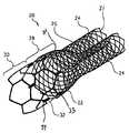
- FIG. 1is a perspective view of an embodiment of the invention comprising a bifurcated stent.
- FIG. 2is a perspective view of an embodiment of the invention comprising a crimping member that engages the two sections of differential compressibility in the trunk region of the stent of FIG. 1 .
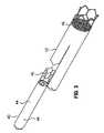
- FIG. 3is a perspective view of an embodiment of the invention comprising a modular mating stent adapted to be received within and assembled with a receiving stent in accordance with another embodiment of the present invention.
- a bifurcated stent 20adapted to resist migration within a body lumen.
- Stent 20includes a trunk region 22 at least one leg region or branches, such as branches 26 and 24 , extending therefrom.
- the trunk region 22 of stent 20includes a first or proximal section 30 and a second or distal section 28 .
- the branches 24 and 26define separate flow paths which branch from the single flow path defined by the trunk region 22 .
- each branch 24 and 26shares a common predetermined compressibility (or flexibility) adapted to permit the branches 24 and 26 and section 28 to conform to the shape of the body lumens surrounding them at their deployment site and to easily advanced through the tortuous confines of body lumen(s).
- the branches 24 and 26 as well as the section 28are substantially self-expandable.
- the proximal section 30 of the trunk region 22is adapted to firmly engage that part of the body lumen surrounding the section 30 at its deployment site adjacent to the bifurcation of a vessel.
- the section 30is deployed by mechanical or balloon expansion and is firmly seated within the vessel to resist stent migration.
- the section 30likewise has a predetermined compressibility, but which is less compressible than that of the distal section 28 or the branches 24 and 26 .
- section 30is constructed from material having a substantially solid, tubular geometry with cellular openings, which may be obtained from a laser cut tube or sheet which formed into a tube.
- the distal section 28 and the branches 24 and 26are integrally formed of one or more strands 31 of material that are interwoven or braided to form the respective portions of the stent 20 .
- the sections 28 and 30may be bonded, welded, or otherwise engaged together to form the trunk region 22 .
- one or more distal members 33 of the proximal section 30 and one or more proximal members 35 of the distal section 28are engaged together by at least one crimping members 32 (better seen in FIG. 2 ).
- a crimping member 32comprises a tubular member or band 37 that is disposed about an overlapping portion of one or more distal members 33 and one or more proximal members 35 . Once properly disposed, the crimping member is crimped or otherwise compressed in order to frictionally engage and retain the respective portions of members 33 and 35 contained therein.
- distal section 28 of the trunk 22 and branches 24 and 26are caused or allowed to self-expand to a predetermined diameter within the vessel(s). Even after the branches 24 and 26 and/or the section 28 are fully expanded, the location of stent 20 may be adjusted before final placement and fixation. Once properly positioned, the proximal section 30 of the trunk 22 is expanded to a predetermined diameter in the vessel via a balloon or other mechanical expansion mechanism such as are known.
- the stent 20will remain fixed in its final position.
- proximal section 30when the proximal section 30 is expanded, it is less compressible than the distal section 28 and delivers a substantial radial resistance to force, preventing stent 20 from working its way away from its originally deployed position.
- the distal section 28 and branches 24 and 26are formed of a conventional material to provide the section 28 and branches 24 and 26 with self-expanding characteristics. Suitable materials include, but are not limited to one or more shape-memory metals such as nitinol, one or more shape memory polymers, etc.
- the proximal section 30is typically formed of any of a variety of materials that provide or can be made to provide greater rigidity or compression resistance than that of the distal section 28 . Such materials may include but are not limited to stainless steel, nitinol, etc.
- a vessel engagement membermay be comprised of one or more hooks, barbs, T-fasteners, and/or other external surface features to assist in firmly engaging the surrounding body lumen.
- the stent 20may be a stent-graft, wherein the stent 20 is provided with a graft lining or covering to provide fluid pathways from the unbifurcated end to the bifurcated end.
- an alternative to the balloon-expandable stainless steel proximal section 30is a balloon-expandable, and thus more rigid, proximal section 30 constructed of nitinol but annealed (i.e., heat treated above the temperature necessary to effect shape-memory retention). Annealing the nitinol transforms its material properties from a shape memory alloy capable of re-expansion to a more rigid structure, conducive to fixation through alternative means such as balloon expansion.
- FIG. 2is a detail view of crimping member 32 represented in FIG. 1 that secures the two sections of differential compressibility (i.e. section 28 and section 30 ) together.
- the exemplary configurationillustrates two braided members 35 of distal section 28 secured to one or more members 33 of the proximal section 30 via crimping member 32 .
- crimping member 32 and/or other portions of the stentmay be at least partially constructed of one or more radiopaque materials.
- stent 20is not limited to the use of crimping members 32 as a securing mechanism between the first and second sections 30 and 38 of the trunk region 22 .
- first section 30 and second section 28may be secured together via welds, chemical or adhesive bonds, direct mechanical engagement (i.e. hooks, etc.) of the members 33 and 35 , and any combinations thereof.
- the proximal section 30 and distal section 28may not be connected at all if their relative positions are maintained in some other way, such as by securing section 28 and section 30 each to the inside of a graft, sleeve or other device via sutures or other securement mechanisms such as sutures.
- the inventionis also directed to a system comprising a modular mating stent 40 and receiving stent 42 , an example of which is shown in FIG. 3 .
- the modular mating stent 40includes a first section 44 of predetermined compressibility adapted to permit section 44 to conform to the shape of a body lumen surrounding section 44 .
- the modular mating stent 40further includes a second section 46 less compressible than first section 44 and adapted to firmly engage that part of receiving stent 42 surrounding second section 46 , i.e. the inner surface of stent 42 in the area where stent 40 is received during in vivo deployment and assembly.
- a graft 48covers modular mating stent 40 and receiving stent 42 , at least in part, defining a fluid passageway.
- First section 44is constructed from braided strands of a shape memory alloy capable of re-expansion
- second section 46is constructed from a non-shape memory alloy in a tubular geometry with cellular openings. Therefore, placement and fixation are achieved through alternative means such as balloon expansion.
- mating stent 40is deployed at least partially within receiving stent 42 as opposed to a body lumen, as represented in FIG. 3 .
- the previously described principles of section 30 of stent 20 firmly engaging the surrounding body lumenapply to second section 46 of modular mating stent 40 firmly engaging the surrounding receiving stent 42 to resist migration and leakage.
- any dependent claim which followsshould be taken as alternatively written in a multiple dependent form from all prior claims which possess all antecedents referenced in such dependent claim if such multiple dependent format is an accepted format within the jurisdiction (e.g. each claim depending directly from claim 1 should be alternatively taken as depending from all previous claims).
- each claim depending directly from claim 1should be alternatively taken as depending from all previous claims.
- the following dependent claimsshould each be also taken as alternatively written in each singly dependent claim format which creates a dependency from a prior antecedent-possessing claim other than the specific claim listed in such dependent claim below.
Landscapes
- Health & Medical Sciences (AREA)
- Heart & Thoracic Surgery (AREA)
- Life Sciences & Earth Sciences (AREA)
- Cardiology (AREA)
- Oral & Maxillofacial Surgery (AREA)
- Transplantation (AREA)
- Engineering & Computer Science (AREA)
- Biomedical Technology (AREA)
- Gastroenterology & Hepatology (AREA)
- Pulmonology (AREA)
- Animal Behavior & Ethology (AREA)
- Vascular Medicine (AREA)
- General Health & Medical Sciences (AREA)
- Public Health (AREA)
- Veterinary Medicine (AREA)
- Prostheses (AREA)
- Media Introduction/Drainage Providing Device (AREA)
- Materials For Medical Uses (AREA)
Abstract
Description
Claims (12)
Priority Applications (6)
| Application Number | Priority Date | Filing Date | Title |
|---|---|---|---|
| US10/643,261US7628806B2 (en) | 2003-08-20 | 2003-08-20 | Stent with improved resistance to migration |
| CA002536169ACA2536169A1 (en) | 2003-08-19 | 2004-08-06 | Stent with improved resistance to migration |
| JP2006523891AJP4750031B2 (en) | 2003-08-20 | 2004-08-06 | Stent with improved resistance to movement |
| PCT/US2004/025396WO2005018499A1 (en) | 2003-08-20 | 2004-08-06 | Stent with improved resistance to migration |
| EP04780261AEP1656082A1 (en) | 2003-08-20 | 2004-08-06 | Stent with improved resistance to migration |
| US12/606,874US20100049291A1 (en) | 2003-08-20 | 2009-10-27 | Stent with improved resistance to migration |
Applications Claiming Priority (1)
| Application Number | Priority Date | Filing Date | Title |
|---|---|---|---|
| US10/643,261US7628806B2 (en) | 2003-08-20 | 2003-08-20 | Stent with improved resistance to migration |
Related Child Applications (1)
| Application Number | Title | Priority Date | Filing Date |
|---|---|---|---|
| US12/606,874DivisionUS20100049291A1 (en) | 2003-08-20 | 2009-10-27 | Stent with improved resistance to migration |
Publications (2)
| Publication Number | Publication Date |
|---|---|
| US20050043784A1 US20050043784A1 (en) | 2005-02-24 |
| US7628806B2true US7628806B2 (en) | 2009-12-08 |
Family
ID=34193828
Family Applications (2)
| Application Number | Title | Priority Date | Filing Date |
|---|---|---|---|
| US10/643,261Expired - Fee RelatedUS7628806B2 (en) | 2003-08-19 | 2003-08-20 | Stent with improved resistance to migration |
| US12/606,874AbandonedUS20100049291A1 (en) | 2003-08-20 | 2009-10-27 | Stent with improved resistance to migration |
Family Applications After (1)
| Application Number | Title | Priority Date | Filing Date |
|---|---|---|---|
| US12/606,874AbandonedUS20100049291A1 (en) | 2003-08-20 | 2009-10-27 | Stent with improved resistance to migration |
Country Status (5)
| Country | Link |
|---|---|
| US (2) | US7628806B2 (en) |
| EP (1) | EP1656082A1 (en) |
| JP (1) | JP4750031B2 (en) |
| CA (1) | CA2536169A1 (en) |
| WO (1) | WO2005018499A1 (en) |
Cited By (16)
| Publication number | Priority date | Publication date | Assignee | Title |
|---|---|---|---|---|
| US8414635B2 (en) | 1999-02-01 | 2013-04-09 | Idev Technologies, Inc. | Plain woven stents |
| US8419788B2 (en) | 2006-10-22 | 2013-04-16 | Idev Technologies, Inc. | Secured strand end devices |
| US8524132B2 (en) | 2010-04-14 | 2013-09-03 | Abbott Cardiovascular Systems Inc. | Method of fabricating an intraluminal scaffold with an enlarged portion |
| US10076428B2 (en) | 2016-08-25 | 2018-09-18 | DePuy Synthes Products, Inc. | Expansion ring for a braided stent |
| US10470871B2 (en) | 2001-12-20 | 2019-11-12 | Trivascular, Inc. | Advanced endovascular graft |
| US10561509B2 (en) | 2013-03-13 | 2020-02-18 | DePuy Synthes Products, Inc. | Braided stent with expansion ring and method of delivery |
| US10603157B2 (en) | 2013-03-13 | 2020-03-31 | DePuy Synthes Products, Inc. | Braid implant delivery and retraction device with distal engagement |
| US10821010B2 (en) | 2014-08-27 | 2020-11-03 | DePuy Synthes Products, Inc. | Method of making a multi-strand implant with enhanced radiopacity |
| US10893963B2 (en) | 2018-08-06 | 2021-01-19 | DePuy Synthes Products, Inc. | Stent delivery with expansion assisting delivery wire |
| US11039944B2 (en) | 2018-12-27 | 2021-06-22 | DePuy Synthes Products, Inc. | Braided stent system with one or more expansion rings |
| US11090175B2 (en) | 2018-07-30 | 2021-08-17 | DePuy Synthes Products, Inc. | Systems and methods of manufacturing and using an expansion ring |
| US20210282948A1 (en)* | 2015-09-18 | 2021-09-16 | Terumo Corporation | Vessel Prosthesis |
| US11129738B2 (en) | 2016-09-30 | 2021-09-28 | DePuy Synthes Products, Inc. | Self-expanding device delivery apparatus with dual function bump |
| US11357648B2 (en) | 2018-08-06 | 2022-06-14 | DePuy Synthes Products, Inc. | Systems and methods of using a braided implant |
| US20240108854A1 (en)* | 2022-09-29 | 2024-04-04 | Neuravi Limited | Catheter with distal braid terminations |
| US12440646B2 (en) | 2021-11-03 | 2025-10-14 | DePuy Synthes Products, Inc. | Catheter braid wire with variable cross-section shape |
Families Citing this family (15)
| Publication number | Priority date | Publication date | Assignee | Title |
|---|---|---|---|---|
| US6290673B1 (en) | 1999-05-20 | 2001-09-18 | Conor Medsystems, Inc. | Expandable medical device delivery system and method |
| JP4888914B2 (en) | 2004-12-08 | 2012-02-29 | イノベーショナル・ホールディングス・エルエルシー | Expandable medical device with different hinge performance |
| US8021413B2 (en)* | 2007-12-27 | 2011-09-20 | Cook Medical Technologies Llc | Low profile medical device |
| US20090287145A1 (en)* | 2008-05-15 | 2009-11-19 | Altura Interventional, Inc. | Devices and methods for treatment of abdominal aortic aneurysms |
| KR101116867B1 (en)* | 2009-08-28 | 2012-03-06 | 김준홍 | The device for delivering optimal tension safaely and effectively in cerclage annuloplasty procedure |
| EP2506799A4 (en)* | 2009-12-01 | 2014-10-29 | Altura Medical Inc | Modular endograft devices and associated systems and methods |
| WO2012040240A1 (en) | 2010-09-20 | 2012-03-29 | Altura Medical, Inc. | Stent graft delivery systems and associated methods |
| US9675473B2 (en) | 2011-12-29 | 2017-06-13 | Boston Scientific Scimed, Inc. | Stent with anti-migration features |
| CA2881535A1 (en) | 2012-08-10 | 2014-02-13 | Altura Medical, Inc. | Stent delivery systems and associated methods |
| WO2014144809A1 (en) | 2013-03-15 | 2014-09-18 | Altura Medical, Inc. | Endograft device delivery systems and associated methods |
| EP2915509A1 (en)* | 2014-03-05 | 2015-09-09 | Cardiatis S.A. | Stent assembly for thoracoabdominal bifurcated aneurysm repair |
| CN109009568B (en) | 2017-06-09 | 2023-10-31 | 上海微创心通医疗科技有限公司 | Mitral valve prosthesis, tricuspid valve prosthesis and stent thereof |
| KR102607268B1 (en) | 2018-07-29 | 2023-11-29 | 비브이더블유 홀딩 에이쥐 | bile duct stent |
| KR102561897B1 (en)* | 2021-01-27 | 2023-08-01 | 주식회사 에스앤지바이오텍 | Stent and manufacturing method thereof |
| US20240156622A1 (en)* | 2022-11-15 | 2024-05-16 | Merit Medical Systems, Inc. | Balloon expandable stent prostheses and balloon expandable branching stent prostheses |
Citations (32)
| Publication number | Priority date | Publication date | Assignee | Title |
|---|---|---|---|---|
| US4655771A (en) | 1982-04-30 | 1987-04-07 | Shepherd Patents S.A. | Prosthesis comprising an expansible or contractile tubular body |
| US4944071A (en) | 1989-06-01 | 1990-07-31 | Marzoli Pietro B | Textile fibre bale breaker |
| US5061275A (en) | 1986-04-21 | 1991-10-29 | Medinvent S.A. | Self-expanding prosthesis |
| US5226913A (en) | 1988-09-01 | 1993-07-13 | Corvita Corporation | Method of making a radially expandable prosthesis |
| US5383892A (en) | 1991-11-08 | 1995-01-24 | Meadox France | Stent for transluminal implantation |
| US5395390A (en) | 1992-05-01 | 1995-03-07 | The Beth Israel Hospital Association | Metal wire stent |
| WO1997017912A1 (en) | 1995-11-13 | 1997-05-22 | Corvita Corporation | Expandable supportive bifurcated endoluminal grafts |
| EP0800801A1 (en) | 1996-04-10 | 1997-10-15 | Advanced Cardiovascular Systems, Inc. | Stent having varied amounts of structural strength along its length |
| US5693086A (en) | 1994-02-09 | 1997-12-02 | Boston Scientific Technology, Inc. | Apparatus for delivering an endoluminal stent or prosthesis |
| US5723004A (en) | 1993-10-21 | 1998-03-03 | Corvita Corporation | Expandable supportive endoluminal grafts |
| US5755735A (en) | 1996-05-03 | 1998-05-26 | Medinol Ltd. | Bifurcated stent and method of making same |
| US5836966A (en) | 1997-05-22 | 1998-11-17 | Scimed Life Systems, Inc. | Variable expansion force stent |
| US5843160A (en) | 1996-04-01 | 1998-12-01 | Rhodes; Valentine J. | Prostheses for aneurysmal and/or occlusive disease at a bifurcation in a vessel, duct, or lumen |
| US5855598A (en) | 1993-10-21 | 1999-01-05 | Corvita Corporation | Expandable supportive branched endoluminal grafts |
| US5906640A (en) | 1994-11-03 | 1999-05-25 | Divysio Solutions Ulc | Bifurcated stent and method for the manufacture and delivery of same |
| US6017363A (en) | 1997-09-22 | 2000-01-25 | Cordis Corporation | Bifurcated axially flexible stent |
| US6068655A (en) | 1996-06-06 | 2000-05-30 | Seguin; Jacques | Endoprosthesis for vascular bifurcation |
| US6102938A (en) | 1997-06-17 | 2000-08-15 | Medtronic Inc. | Endoluminal prosthetic bifurcation shunt |
| WO2000076423A1 (en) | 1998-12-03 | 2000-12-21 | Edwards Lifesciences Corporation | Methods and apparatus for intraluminal placement of a bifurcated intraluminal graft |
| US6168621B1 (en) | 1998-05-29 | 2001-01-02 | Scimed Life Systems, Inc. | Balloon expandable stent with a self-expanding portion |
| WO2001035864A1 (en) | 1999-11-16 | 2001-05-25 | Boston Scientific Limited | Multi-section filamentary endoluminal stent |
| US6273910B1 (en) | 1999-03-11 | 2001-08-14 | Advanced Cardiovascular Systems, Inc. | Stent with varying strut geometry |
| US6273909B1 (en) | 1998-10-05 | 2001-08-14 | Teramed Inc. | Endovascular graft system |
| US6325819B1 (en)* | 1996-08-19 | 2001-12-04 | Cook Incorporated | Endovascular prosthetic device, an endovascular graft prothesis with such a device, and a method for repairing an abdominal aortic aneurysm |
| US6387120B2 (en) | 1999-12-09 | 2002-05-14 | Advanced Cardiovascular Systems, Inc. | Stent and catheter assembly and method for treating bifurcations |
| WO2003004960A1 (en) | 2001-07-02 | 2003-01-16 | Barry Anthony Hodgkinson | System with connectable blasting cartridges |
| US20030033002A1 (en)* | 1998-09-30 | 2003-02-13 | Edwards Lifesciences, Llc | Aorto uni-iliac graft |
| US6520988B1 (en) | 1997-09-24 | 2003-02-18 | Medtronic Ave, Inc. | Endolumenal prosthesis and method of use in bifurcation regions of body lumens |
| US20030114923A1 (en)* | 2001-11-14 | 2003-06-19 | Swanick Thomas M. | Graft and method of making |
| WO2003049640A2 (en) | 2001-12-05 | 2003-06-19 | Scimed Life Systems, Inc. | Combined balloon-expanding and self-expanding stent |
| US20030195609A1 (en) | 2002-04-10 | 2003-10-16 | Scimed Life Systems, Inc. | Hybrid stent |
| US7131991B2 (en)* | 2002-04-24 | 2006-11-07 | Medtronic Vascular, Inc. | Endoluminal prosthetic assembly and extension method |
Family Cites Families (11)
| Publication number | Priority date | Publication date | Assignee | Title |
|---|---|---|---|---|
| US5749920A (en)* | 1983-12-09 | 1998-05-12 | Endovascular Technologies, Inc. | Multicapsule intraluminal grafting system and method |
| US4787899A (en)* | 1983-12-09 | 1988-11-29 | Lazarus Harrison M | Intraluminal graft device, system and method |
| US5064435A (en)* | 1990-06-28 | 1991-11-12 | Schneider (Usa) Inc. | Self-expanding prosthesis having stable axial length |
| US5320100A (en)* | 1991-09-16 | 1994-06-14 | Atrium Medical Corporation | Implantable prosthetic device having integral patency diagnostic indicia |
| JPH11511352A (en)* | 1995-08-24 | 1999-10-05 | インプラ・インコーポレーテッド | Covered intraluminal stent and method of assembling the same |
| US5843119A (en)* | 1996-10-23 | 1998-12-01 | United States Surgical Corporation | Apparatus and method for dilatation of a body lumen and delivery of a prothesis therein |
| US6315791B1 (en)* | 1996-12-03 | 2001-11-13 | Atrium Medical Corporation | Self-expanding prothesis |
| US6129756A (en)* | 1998-03-16 | 2000-10-10 | Teramed, Inc. | Biluminal endovascular graft system |
| US6398807B1 (en)* | 2000-01-31 | 2002-06-04 | Scimed Life Systems, Inc. | Braided branching stent, method for treating a lumen therewith, and process for manufacture therefor |
| US20030050684A1 (en)* | 2001-09-10 | 2003-03-13 | Abrams Robert M. | Internal restraint for delivery of self-expanding stents |
| WO2002067816A1 (en)* | 2001-02-26 | 2002-09-06 | Scimed Life Systems, Inc. | Bifurcated stent and delivery system |
- 2003
- 2003-08-20USUS10/643,261patent/US7628806B2/ennot_activeExpired - Fee Related
- 2004
- 2004-08-06CACA002536169Apatent/CA2536169A1/ennot_activeAbandoned
- 2004-08-06WOPCT/US2004/025396patent/WO2005018499A1/enactiveApplication Filing
- 2004-08-06EPEP04780261Apatent/EP1656082A1/ennot_activeWithdrawn
- 2004-08-06JPJP2006523891Apatent/JP4750031B2/ennot_activeExpired - Fee Related
- 2009
- 2009-10-27USUS12/606,874patent/US20100049291A1/ennot_activeAbandoned
Patent Citations (38)
| Publication number | Priority date | Publication date | Assignee | Title |
|---|---|---|---|---|
| US4655771A (en) | 1982-04-30 | 1987-04-07 | Shepherd Patents S.A. | Prosthesis comprising an expansible or contractile tubular body |
| US4655771B1 (en) | 1982-04-30 | 1996-09-10 | Medinvent Ams Sa | Prosthesis comprising an expansible or contractile tubular body |
| US5061275A (en) | 1986-04-21 | 1991-10-29 | Medinvent S.A. | Self-expanding prosthesis |
| US5226913A (en) | 1988-09-01 | 1993-07-13 | Corvita Corporation | Method of making a radially expandable prosthesis |
| US4944071A (en) | 1989-06-01 | 1990-07-31 | Marzoli Pietro B | Textile fibre bale breaker |
| US5383892A (en) | 1991-11-08 | 1995-01-24 | Meadox France | Stent for transluminal implantation |
| US5395390A (en) | 1992-05-01 | 1995-03-07 | The Beth Israel Hospital Association | Metal wire stent |
| US5639278A (en) | 1993-10-21 | 1997-06-17 | Corvita Corporation | Expandable supportive bifurcated endoluminal grafts |
| US5723004A (en) | 1993-10-21 | 1998-03-03 | Corvita Corporation | Expandable supportive endoluminal grafts |
| US5855598A (en) | 1993-10-21 | 1999-01-05 | Corvita Corporation | Expandable supportive branched endoluminal grafts |
| US5693086A (en) | 1994-02-09 | 1997-12-02 | Boston Scientific Technology, Inc. | Apparatus for delivering an endoluminal stent or prosthesis |
| US5906640A (en) | 1994-11-03 | 1999-05-25 | Divysio Solutions Ulc | Bifurcated stent and method for the manufacture and delivery of same |
| WO1997017912A1 (en) | 1995-11-13 | 1997-05-22 | Corvita Corporation | Expandable supportive bifurcated endoluminal grafts |
| US5843160A (en) | 1996-04-01 | 1998-12-01 | Rhodes; Valentine J. | Prostheses for aneurysmal and/or occlusive disease at a bifurcation in a vessel, duct, or lumen |
| EP0800801A1 (en) | 1996-04-10 | 1997-10-15 | Advanced Cardiovascular Systems, Inc. | Stent having varied amounts of structural strength along its length |
| US5755735A (en) | 1996-05-03 | 1998-05-26 | Medinol Ltd. | Bifurcated stent and method of making same |
| US6068655A (en) | 1996-06-06 | 2000-05-30 | Seguin; Jacques | Endoprosthesis for vascular bifurcation |
| US6325819B1 (en)* | 1996-08-19 | 2001-12-04 | Cook Incorporated | Endovascular prosthetic device, an endovascular graft prothesis with such a device, and a method for repairing an abdominal aortic aneurysm |
| US5836966A (en) | 1997-05-22 | 1998-11-17 | Scimed Life Systems, Inc. | Variable expansion force stent |
| US6146403A (en) | 1997-05-22 | 2000-11-14 | Scimed Life Systems, Inc. | Variable expansion force stent |
| US6423084B1 (en) | 1997-05-22 | 2002-07-23 | Scimed Life Systems, Inc | Variable expansion force stent |
| US6102938A (en) | 1997-06-17 | 2000-08-15 | Medtronic Inc. | Endoluminal prosthetic bifurcation shunt |
| US6017363A (en) | 1997-09-22 | 2000-01-25 | Cordis Corporation | Bifurcated axially flexible stent |
| US6520988B1 (en) | 1997-09-24 | 2003-02-18 | Medtronic Ave, Inc. | Endolumenal prosthesis and method of use in bifurcation regions of body lumens |
| US6168621B1 (en) | 1998-05-29 | 2001-01-02 | Scimed Life Systems, Inc. | Balloon expandable stent with a self-expanding portion |
| US20030033002A1 (en)* | 1998-09-30 | 2003-02-13 | Edwards Lifesciences, Llc | Aorto uni-iliac graft |
| US20020019665A1 (en)* | 1998-09-30 | 2002-02-14 | Mark Dehdashtian | Methods and apparatus for intraluminal placement of a bifurcated intraluminal graft |
| US6273909B1 (en) | 1998-10-05 | 2001-08-14 | Teramed Inc. | Endovascular graft system |
| WO2000076423A1 (en) | 1998-12-03 | 2000-12-21 | Edwards Lifesciences Corporation | Methods and apparatus for intraluminal placement of a bifurcated intraluminal graft |
| US6273910B1 (en) | 1999-03-11 | 2001-08-14 | Advanced Cardiovascular Systems, Inc. | Stent with varying strut geometry |
| WO2001035864A1 (en) | 1999-11-16 | 2001-05-25 | Boston Scientific Limited | Multi-section filamentary endoluminal stent |
| US6387120B2 (en) | 1999-12-09 | 2002-05-14 | Advanced Cardiovascular Systems, Inc. | Stent and catheter assembly and method for treating bifurcations |
| WO2003004960A1 (en) | 2001-07-02 | 2003-01-16 | Barry Anthony Hodgkinson | System with connectable blasting cartridges |
| US20030114923A1 (en)* | 2001-11-14 | 2003-06-19 | Swanick Thomas M. | Graft and method of making |
| WO2003049640A2 (en) | 2001-12-05 | 2003-06-19 | Scimed Life Systems, Inc. | Combined balloon-expanding and self-expanding stent |
| US20030195609A1 (en) | 2002-04-10 | 2003-10-16 | Scimed Life Systems, Inc. | Hybrid stent |
| WO2003086237A1 (en) | 2002-04-10 | 2003-10-23 | Scimed Life Systems, Inc. | Hybrid stent |
| US7131991B2 (en)* | 2002-04-24 | 2006-11-07 | Medtronic Vascular, Inc. | Endoluminal prosthetic assembly and extension method |
Non-Patent Citations (4)
| Title |
|---|
| A Non-Final Office Action in the present U.S. Appl. No. 10/643,261 dated Sep. 5, 2006. 12 pgs. |
| An Information Disclosure Statement filed in the present U.S. Appl. No. 10/643,261 dated Nov. 18, 2003. 8 pgs. |
| Communication pursuant to Article 94(3) EPC from related European Application No. 04 780 261.6-2320. May 13, 2009. 3 pgs. |
| Communication Pursuant to Article 96(2) EPC, for application 04 780 261.6-2310, dated Oct. 19, 2007. |
Cited By (36)
| Publication number | Priority date | Publication date | Assignee | Title |
|---|---|---|---|---|
| US8974516B2 (en) | 1999-02-01 | 2015-03-10 | Board Of Regents, The University Of Texas System | Plain woven stents |
| US9925074B2 (en) | 1999-02-01 | 2018-03-27 | Board Of Regents, The University Of Texas System | Plain woven stents |
| US8876880B2 (en) | 1999-02-01 | 2014-11-04 | Board Of Regents, The University Of Texas System | Plain woven stents |
| US8414635B2 (en) | 1999-02-01 | 2013-04-09 | Idev Technologies, Inc. | Plain woven stents |
| US11439497B2 (en) | 2001-12-20 | 2022-09-13 | Trivascular, Inc. | Advanced endovascular graft |
| US10470871B2 (en) | 2001-12-20 | 2019-11-12 | Trivascular, Inc. | Advanced endovascular graft |
| US9408729B2 (en) | 2006-10-22 | 2016-08-09 | Idev Technologies, Inc. | Secured strand end devices |
| US10470902B2 (en) | 2006-10-22 | 2019-11-12 | Idev Technologies, Inc. | Secured strand end devices |
| US9408730B2 (en) | 2006-10-22 | 2016-08-09 | Idev Technologies, Inc. | Secured strand end devices |
| US8966733B2 (en) | 2006-10-22 | 2015-03-03 | Idev Technologies, Inc. | Secured strand end devices |
| US9585776B2 (en) | 2006-10-22 | 2017-03-07 | Idev Technologies, Inc. | Secured strand end devices |
| US9629736B2 (en) | 2006-10-22 | 2017-04-25 | Idev Technologies, Inc. | Secured strand end devices |
| US9895242B2 (en) | 2006-10-22 | 2018-02-20 | Idev Technologies, Inc. | Secured strand end devices |
| US8739382B2 (en) | 2006-10-22 | 2014-06-03 | Idev Technologies, Inc. | Secured strand end devices |
| US9149374B2 (en) | 2006-10-22 | 2015-10-06 | Idev Technologies, Inc. | Methods for manufacturing secured strand end devices |
| US8419788B2 (en) | 2006-10-22 | 2013-04-16 | Idev Technologies, Inc. | Secured strand end devices |
| US8524132B2 (en) | 2010-04-14 | 2013-09-03 | Abbott Cardiovascular Systems Inc. | Method of fabricating an intraluminal scaffold with an enlarged portion |
| US10561509B2 (en) | 2013-03-13 | 2020-02-18 | DePuy Synthes Products, Inc. | Braided stent with expansion ring and method of delivery |
| US10603157B2 (en) | 2013-03-13 | 2020-03-31 | DePuy Synthes Products, Inc. | Braid implant delivery and retraction device with distal engagement |
| US11529249B2 (en) | 2013-03-13 | 2022-12-20 | DePuy Synthes Products, Inc. | Braided stent with expansion ring and method of delivery |
| US11452623B2 (en) | 2013-03-13 | 2022-09-27 | DePuy Synthes Products, Inc. | Braided stent with expansion ring and method of delivery |
| US10821010B2 (en) | 2014-08-27 | 2020-11-03 | DePuy Synthes Products, Inc. | Method of making a multi-strand implant with enhanced radiopacity |
| US12329664B2 (en)* | 2015-09-18 | 2025-06-17 | Terumo Corporation | Vessel prosthesis |
| US20210282948A1 (en)* | 2015-09-18 | 2021-09-16 | Terumo Corporation | Vessel Prosthesis |
| US10076428B2 (en) | 2016-08-25 | 2018-09-18 | DePuy Synthes Products, Inc. | Expansion ring for a braided stent |
| US10821008B2 (en) | 2016-08-25 | 2020-11-03 | DePuy Synthes Products, Inc. | Expansion ring for a braided stent |
| US11129738B2 (en) | 2016-09-30 | 2021-09-28 | DePuy Synthes Products, Inc. | Self-expanding device delivery apparatus with dual function bump |
| US12064363B2 (en) | 2016-09-30 | 2024-08-20 | DePuy Synthes Products, Inc. | Self-expanding device delivery apparatus with dual function bump |
| US11090175B2 (en) | 2018-07-30 | 2021-08-17 | DePuy Synthes Products, Inc. | Systems and methods of manufacturing and using an expansion ring |
| US11497638B2 (en) | 2018-07-30 | 2022-11-15 | DePuy Synthes Products, Inc. | Systems and methods of manufacturing and using an expansion ring |
| US11357648B2 (en) | 2018-08-06 | 2022-06-14 | DePuy Synthes Products, Inc. | Systems and methods of using a braided implant |
| US10893963B2 (en) | 2018-08-06 | 2021-01-19 | DePuy Synthes Products, Inc. | Stent delivery with expansion assisting delivery wire |
| US12004977B2 (en) | 2018-08-06 | 2024-06-11 | DePuy Synthes Products, Inc. | Systems and methods of using a braided implant |
| US11039944B2 (en) | 2018-12-27 | 2021-06-22 | DePuy Synthes Products, Inc. | Braided stent system with one or more expansion rings |
| US12440646B2 (en) | 2021-11-03 | 2025-10-14 | DePuy Synthes Products, Inc. | Catheter braid wire with variable cross-section shape |
| US20240108854A1 (en)* | 2022-09-29 | 2024-04-04 | Neuravi Limited | Catheter with distal braid terminations |
Also Published As
| Publication number | Publication date |
|---|---|
| CA2536169A1 (en) | 2005-03-03 |
| US20100049291A1 (en) | 2010-02-25 |
| US20050043784A1 (en) | 2005-02-24 |
| WO2005018499A1 (en) | 2005-03-03 |
| EP1656082A1 (en) | 2006-05-17 |
| JP4750031B2 (en) | 2011-08-17 |
| JP2007533347A (en) | 2007-11-22 |
| WO2005018499A8 (en) | 2006-06-22 |
Similar Documents
| Publication | Publication Date | Title |
|---|---|---|
| US7628806B2 (en) | Stent with improved resistance to migration | |
| US8632579B2 (en) | Bifurcated stent and delivery system | |
| US7799064B2 (en) | Bifurcated stent and delivery system | |
| US7169177B2 (en) | Bifurcated stent | |
| US6695877B2 (en) | Bifurcated stent | |
| US6099559A (en) | Endoluminal support assembly with capped ends | |
| US8012197B2 (en) | Hybrid ballon expandable/self-expanding stent | |
| US7959669B2 (en) | Bifurcated stent with open ended side branch support | |
| US8298278B2 (en) | Bifurcated stent with improvement securement | |
| JP2009507558A (en) | Overlapping stent | |
| CA2618215A1 (en) | Stent with expanding side branch geometry | |
| JP2008502441A (en) | Stent delivery system | |
| CA2630246A1 (en) | Bifurcated stent with multiple side branch access | |
| US20090259299A1 (en) | Side Branch Stent Having a Proximal Flexible Material Section |
Legal Events
| Date | Code | Title | Description |
|---|---|---|---|
| AS | Assignment | Owner name:SCIMED LIFE SYSTEMS, INC., MINNESOTA Free format text:ASSIGNMENT OF ASSIGNORS INTEREST;ASSIGNORS:YAMPOLSKY, ILYA;SPIRIDIGLIOZZI, JOHN;REEL/FRAME:014088/0922 Effective date:20030805 | |
| AS | Assignment | Owner name:BOSTON SCIENTIFIC SCIMED, INC., MINNESOTA Free format text:CHANGE OF NAME;ASSIGNOR:SCIMED LIFE SYSTEMS, INC.;REEL/FRAME:018505/0868 Effective date:20050101 Owner name:BOSTON SCIENTIFIC SCIMED, INC.,MINNESOTA Free format text:CHANGE OF NAME;ASSIGNOR:SCIMED LIFE SYSTEMS, INC.;REEL/FRAME:018505/0868 Effective date:20050101 | |
| FEPP | Fee payment procedure | Free format text:PAYOR NUMBER ASSIGNED (ORIGINAL EVENT CODE: ASPN); ENTITY STATUS OF PATENT OWNER: LARGE ENTITY | |
| CC | Certificate of correction | ||
| FPAY | Fee payment | Year of fee payment:4 | |
| AS | Assignment | Owner name:ACACIA RESEARCH GROUP LLC, TEXAS Free format text:ASSIGNMENT OF ASSIGNORS INTEREST;ASSIGNOR:BOSTON SCIENTIFIC SCIMED, INC.;REEL/FRAME:030694/0461 Effective date:20121220 | |
| AS | Assignment | Owner name:LIFESHIELD SCIENCES LLC, TEXAS Free format text:ASSIGNMENT OF ASSIGNORS INTEREST;ASSIGNOR:ACACIA RESEARCH GROUP LLC;REEL/FRAME:030740/0225 Effective date:20130515 | |
| REMI | Maintenance fee reminder mailed | ||
| LAPS | Lapse for failure to pay maintenance fees | Free format text:PATENT EXPIRED FOR FAILURE TO PAY MAINTENANCE FEES (ORIGINAL EVENT CODE: EXP.) | |
| STCH | Information on status: patent discontinuation | Free format text:PATENT EXPIRED DUE TO NONPAYMENT OF MAINTENANCE FEES UNDER 37 CFR 1.362 | |
| FP | Lapsed due to failure to pay maintenance fee | Effective date:20171208 |