US7628794B2 - Prosthetic revision knee system - Google Patents
Prosthetic revision knee systemDownload PDFInfo
- Publication number
- US7628794B2 US7628794B2US11/100,349US10034905AUS7628794B2US 7628794 B2US7628794 B2US 7628794B2US 10034905 AUS10034905 AUS 10034905AUS 7628794 B2US7628794 B2US 7628794B2
- Authority
- US
- United States
- Prior art keywords
- cutting block
- bushing
- femoral
- femoral component
- anterior
- Prior art date
- Legal status (The legal status is an assumption and is not a legal conclusion. Google has not performed a legal analysis and makes no representation as to the accuracy of the status listed.)
- Active, expires
Links
- 210000003127kneeAnatomy0.000titleclaimsabstractdescription28
- 238000005520cutting processMethods0.000claimsabstractdescription66
- 210000000689upper legAnatomy0.000claimsabstractdescription44
- 238000000034methodMethods0.000claimsabstractdescription23
- 238000002513implantationMethods0.000claimsabstractdescription3
- 241001227561ValgusSpecies0.000claimsdescription10
- 230000013011matingEffects0.000claimsdescription10
- 230000001154acute effectEffects0.000claimsdescription7
- 238000002271resectionMethods0.000claimsdescription6
- 238000001356surgical procedureMethods0.000claimsdescription2
- 239000007943implantSubstances0.000abstractdescription15
- RTAQQCXQSZGOHL-UHFFFAOYSA-NTitaniumChemical compound[Ti]RTAQQCXQSZGOHL-UHFFFAOYSA-N0.000description4
- 210000003484anatomyAnatomy0.000description4
- 210000000629knee jointAnatomy0.000description4
- 239000000463materialSubstances0.000description4
- 239000010936titaniumSubstances0.000description4
- 229910000684Cobalt-chromeInorganic materials0.000description3
- 239000010952cobalt-chromeSubstances0.000description3
- 230000000295complement effectEffects0.000description3
- 230000006378damageEffects0.000description3
- 239000010935stainless steelSubstances0.000description3
- 229910001220stainless steelInorganic materials0.000description3
- 229910052719titaniumInorganic materials0.000description3
- 239000000560biocompatible materialSubstances0.000description2
- 230000028993immune responseEffects0.000description2
- 208000015181infectious diseaseDiseases0.000description2
- 230000002757inflammatory effectEffects0.000description2
- 238000003780insertionMethods0.000description2
- 230000037431insertionEffects0.000description2
- 206010065687Bone lossDiseases0.000description1
- 229910001200FerrotitaniumInorganic materials0.000description1
- 208000027418Wounds and injuryDiseases0.000description1
- 229910045601alloyInorganic materials0.000description1
- 239000000956alloySubstances0.000description1
- 210000000988bone and boneAnatomy0.000description1
- 230000001054cortical effectEffects0.000description1
- 230000006866deteriorationEffects0.000description1
- 208000014674injuryDiseases0.000description1
- 230000000399orthopedic effectEffects0.000description1
- 239000013618particulate matterSubstances0.000description1
- 238000007493shaping processMethods0.000description1
- 210000002303tibiaAnatomy0.000description1
- 210000001519tissueAnatomy0.000description1
Images


Classifications
- A—HUMAN NECESSITIES
- A61—MEDICAL OR VETERINARY SCIENCE; HYGIENE
- A61F—FILTERS IMPLANTABLE INTO BLOOD VESSELS; PROSTHESES; DEVICES PROVIDING PATENCY TO, OR PREVENTING COLLAPSING OF, TUBULAR STRUCTURES OF THE BODY, e.g. STENTS; ORTHOPAEDIC, NURSING OR CONTRACEPTIVE DEVICES; FOMENTATION; TREATMENT OR PROTECTION OF EYES OR EARS; BANDAGES, DRESSINGS OR ABSORBENT PADS; FIRST-AID KITS
- A61F2/00—Filters implantable into blood vessels; Prostheses, i.e. artificial substitutes or replacements for parts of the body; Appliances for connecting them with the body; Devices providing patency to, or preventing collapsing of, tubular structures of the body, e.g. stents
- A61F2/02—Prostheses implantable into the body
- A61F2/30—Joints
- A61F2/38—Joints for elbows or knees
- A61F2/3859—Femoral components
- A—HUMAN NECESSITIES
- A61—MEDICAL OR VETERINARY SCIENCE; HYGIENE
- A61B—DIAGNOSIS; SURGERY; IDENTIFICATION
- A61B17/00—Surgical instruments, devices or methods
- A61B17/14—Surgical saws
- A61B17/15—Guides therefor
- A61B17/154—Guides therefor for preparing bone for knee prosthesis
- A61B17/155—Cutting femur
- A—HUMAN NECESSITIES
- A61—MEDICAL OR VETERINARY SCIENCE; HYGIENE
- A61F—FILTERS IMPLANTABLE INTO BLOOD VESSELS; PROSTHESES; DEVICES PROVIDING PATENCY TO, OR PREVENTING COLLAPSING OF, TUBULAR STRUCTURES OF THE BODY, e.g. STENTS; ORTHOPAEDIC, NURSING OR CONTRACEPTIVE DEVICES; FOMENTATION; TREATMENT OR PROTECTION OF EYES OR EARS; BANDAGES, DRESSINGS OR ABSORBENT PADS; FIRST-AID KITS
- A61F2/00—Filters implantable into blood vessels; Prostheses, i.e. artificial substitutes or replacements for parts of the body; Appliances for connecting them with the body; Devices providing patency to, or preventing collapsing of, tubular structures of the body, e.g. stents
- A61F2/02—Prostheses implantable into the body
- A61F2/30—Joints
- A61F2002/30001—Additional features of subject-matter classified in A61F2/28, A61F2/30 and subgroups thereof
- A61F2002/30316—The prosthesis having different structural features at different locations within the same prosthesis; Connections between prosthetic parts; Special structural features of bone or joint prostheses not otherwise provided for
- A61F2002/30535—Special structural features of bone or joint prostheses not otherwise provided for
- A61F2002/30604—Special structural features of bone or joint prostheses not otherwise provided for modular
Definitions
- the present inventionrelates to revision knee implants and surgical orthopedic cutting instruments, and more particularly relates to an improved revision knee femoral prosthesis and corresponding improved cutting block apparatus for shaping a distal femur of a patient prior to implantation of the femoral prosthesis.
- a conventional knee prosthesisgenerally has a smooth continuous outer curvature that faces a corresponding component attached to the patient's tibia, and includes a femoral component, a femoral stem, a patellar component and a tibial component.
- the femoral componenttypically includes a pair of spaced apart condylar portions that articulate with the tibial component. Additionally, the femoral component usually has an intercondylar surface located between the two condylar portions.
- the femoral stemtypically is connected to the intercondylar surface of the femoral component by means of a bolt that passes through a bore in the intercondylar surface.
- the femoral stemis, in use, inserted into a reamed intramedullary canal of the femur.
- the patellar componentarticulates with the anterior surface of the femoral component.
- the femoral stem of the prosthesistypically is set at an angle, from lateral to medial, to match the patient's valgus angle, which is the angle between the axis of the femoral shaft and an imaginary vertical line extending from the distal femur to the center of the femoral head.
- a typical femoral component of a knee prosthesisprovides five intersecting flat surfaces. One surface is adapted to engage the anterior cortical surface of the femur. Another surface is adapted to face the posterior surface of the femur. Still another surface is adapted to engage the distal end of the patient's femur. Additionally, a pair of chamfer surfaces form diagonally extending surfaces which form an interface between the distal surface and the respective anterior and posterior surfaces.
- the surgeonBefore beginning a cutting operation, the surgeon needs to orient a cutting guide in anterior and posterior directions relative to the patient's femur and also relative to the valgus angle of the patient's femur. A surgeon needs to form five separate cuts on the patient's distal femur in order to prepare the distal femur to receive the femoral prosthesis.
- One of the problems encountered by the surgeonis the proper orientation of the cuts so that the prosthesis will fit the femur with the correct orientation.
- the anterior-posterior position of the femoral stemusually is not adjustable or only adjustable in limited increments, in both cases resulting in poor alignment of the femoral prosthesis with respect to the intramedullary canal of the femur or an unbalanced flexion gap, either of which can lead to deterioration of the implant.
- One typical revision knee systemprovides incremental anterior-posterior positioning by means of three interchangeable screw heads which permit limited variation of the anterior/posterior position from the norm, i.e., 0 mm, limited to increments of +3 and ⁇ 3 mm.
- the femoral stemis attached to the femoral component by means of a nut and bolt. If the bolt loosens, it can migrate into the knee joint, resulting in injury to the surrounding tissue and damage to or interference with the prosthesis. Additionally, such nut and bolt systems can introduce particulate matter into the knee joint which can cause infection or lead to inflammatory immune responses.
- a prosthetic revision knee systemthat allows for an infinite adjustment of the anterior/posterior position of the femoral stem to suit a wide range of patient anatomies, that permits a proper alignment of the valgus angle of the femoral stem in order to accommodate the anatomical constraints of a variety of patients, that optimizes the positioning of a femoral component and/or femoral stem vis a vis the available bone; and that provides a femoral stem locking system that will not migrate into the knee joint or cause damage to the articular surface of the implant which may lead to infection or inflammatory immune responses.
- the present inventionfulfills this need by providing a method for surgically implanting an improved revision knee femoral prosthesis utilizing an improved cutting block system for revision knee surgery in a patient, comprised of reaming the intramedullary canal of a distal femur of the patient to enlarge the intramedullary canal; inserting into the intramedullary canal a trial stem attached to a cutting block having a front surface and a back surface, in which the front surface has incremental markings thereon, wherein the trial stem is hingedly attached to the back surface of the cutting block by means of a threaded bolt therein, and further wherein the trial stem rotates laterally about 10 degrees around a longitudinal axis perpendicularly to the back surface of the cutting block to allow adaptability to a multitude of valgus angles.
- the inventionalso inheres in a femoral prosthesis comprising a femoral component having incremental markings thereon corresponding to incremental markings on the corresponding cutting block.
- FIG. 1is a perspective view of a bushing and femoral stem affixed onto an engagement surface of a femoral component;
- FIG. 2Ais a perspective view of an embodiment of a femoral component.
- FIG. 2Bis a perspective view of a femoral stem attached to a bushing;
- FIG. 3Ais a side view of a femoral component having a bushing affixed thereon and a femoral stem attached to the bushing.
- FIG. 3Bis a front view of a femoral component having a bushing affixed thereon and a femoral stem attached to the bushing;
- FIG. 4Ais an exploded front view of a bushing.
- FIG. 4Bis an end view of a base portion of a bushing.
- FIG. 4Cis an exploded perspective view of a set screw;
- FIG. 5is a perspective view of a front section of a cutting block having a trial stem attached thereto;
- FIG. 6is a perspective view of a back section of a cutting block having a trial stem attached thereto.
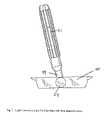
- FIG. 7is a side view of a cutting block having a trial stem attached thereto.
- the present inventionprovides a method for implanting an improved prosthetic revision knee utilizing an improved cutting block apparatus which allows for an infinite adjustment of the anterior/posterior position of a femoral stem to suit a wide range of patient anatomies, which permits a proper alignment of the valgus angle of the femoral stem in order to accommodate the anatomical constraints of a variety of patients, and which utilizes a femoral stem locking system that will not migrate into the knee joint.
- FIGS. 1 through 7illustrate various embodiments of the prosthetic revision knee and cutting block system utilized in the method of the present invention.
- the method of the present invention for surgically implanting a prosthetic revision knee implant 10 in a patientis comprised of a femoral component 15 and a femoral stem 20 which, when in use, are surgically implanted to a distal femur (not shown) which has been surgically prepared to accept the implant 10 by means of a cutting block 40 , wherein the femoral component 15 and the cutting block 40 both have corresponding incremental markings 28 , 58 thereon to achieve a proper alignment of the implant 10 with the distal femur of the patient.
- the method of the present inventionprovides for surgically implanting a prosthetic revision knee implant 10 which includes a femoral component 15 and a femoral stem 20 into a patient ( FIG. 1 ), comprised of reaming the intramedullary canal of a distal femur of the patient to enlarge the intramedullary canal.
- a trial stem 51is attached to a cutting block 40 , which, when in use, is inserted into the intramedullary canal of a patient.
- the cutting block 40has a front surface 52 ( FIG. 5 ) and a back surface 61 ( FIG. 6 ) in which the front surface 52 has incremental markings 58 thereon.
- the trial stem 51is hingedly attached to the back surface 61 of the cutting block 40 by means of a cutting block bushing 59 , in which the cutting block bushing 59 is threadably engaged to a threaded bolt 63 of the cutting block 40 .
- the trial stem 51rotates laterally about 10 degrees around a longitudinal axis perpendicular to the back surface 61 of the cutting block 40 .
- the surgeonplaces the trial stem 51 attached to the cutting block 40 by means of the cutting block bushing 59 into the intramedullary canal of the patient's femur.
- the cutting block 40then is positioned adjacent to as much available area as possible of the distal femur of the patient by adjusting the cutting block 40 position by means of an adjustment screw 53 which moves the cutting block 40 in an anterior-posterior direction by means of the threaded bolt 63 .
- the front surface 52 of the cutting block 40has incremental markings 58 thereon.
- the adjustment position of the cutting block 40is noted by reading the value of the incremental marking 58 position of the cutting block 40 thus positioned.
- the front surface 52 of the cutting blockhas a plurality of cutting slots defined therein so as to allow the surgeon to make a plurality, and preferably four, separate cuts on the patient's distal femur in order to prepare the distal femur to receive the implant 10 .
- the cutting slotsare comprised of an anterior resection slot 54 that makes a flat cut on the anterior portion of the distal femur, an anterior chamfer slot 56 that makes an angled cut that corresponds to the angle of the femoral component 15 , a posterior chamfer slot 55 that makes another angled cut that corresponds to another angle of the femoral component 15 , and a plurality of posterior resection slots 57 that allow for one or more flat step resections of the posterior portion of the distal femur.
- the femoral component 15has an anterior surface 21 and a posterior surface 22 , and preferably has a pair of spaced-apart condylar portions 23 that define an intercondylar region 24 .
- the condylar portions 23allow the femoral component 15 to articulate with a tibial component (not shown).
- the femoral component 15is preferably symmetrical so that it can be used in either the right or left knee of the patient.
- the intercondylar region 24can have almost any length or width within the limitations of the femoral component 15 and within anatomical limitations of the patient. Preferably, the intercondylar region 24 spans the length of the femoral component 15 in the anterior-posterior direction. The intercondylar region 24 may vary in width.
- the intercondylar region 24has an elongate engagement surface 25 extending in the anterior-posterior direction.
- the engagement surface 25can be any shape or size of surface (within the limitations of the femoral component 15 and within anatomical limitations of the patient) which allows for complementary engagement with another surface.
- the engagement surface 25includes opposing rails 26 .
- the engagement surface 25preferably spans the entire length of the intercondylar region 24 to maximize the range of anterior/posterior offset of the femoral stem 20 .
- the engagement surface 25can span a shorter length of the intercondylar region 24 while still offering a range of anterior-posterior positioning not found in prior art revision knee systems.
- a bushinghaving a bore 43 therethrough and an upper portion 44 defining a major bore aperture 64 therein and a base portion 45 defining a minor bore 65 therein, is configured for sliding engagement along the engagement surface 25 of the intercondylar region 24 .
- both the major bore aperture 64 and the minor bore 65are threaded.
- the base portion 45 of the bushing 30includes mating surfaces 41 .
- the mating surfaces 41can be any shape or size of surface (within the limitations of the femoral component 15 and within anatomical limitations of the patient) which allow for engagement with the engagement surface 25 of the intercondylar region 24 of the femoral component 15 , such as rectangular grooves.
- the mating surfaces 41are in the form of dovetails 42 .
- the base portion 45 of the bushing 30may, but need not, be the same length or width as the upper portion 44 .
- the bushing 30can be shaped in a variety of configurations. Preferably, the bushing 30 is symmetrical so that it can be used in either the right or left knee, with a surgeon only having to rotate the bushing 30 by 180° to have it match the valgus angle for either the right or left knee.
- the bore 43 of the bushing 30extends from the upper portion 44 to the base portion 45 of the bushing 30 .
- the diameter of the bore 43is wide enough to allow a locking member 32 to pass through the bore 43 from the upper portion 44 to the base portion 45 , even if the bushing 30 is canted at an acute angle.
- the locking member 32is configured to fit snugly in the base portion 45 of the bushing 30 . Therefore, the diameter of the bore 43 need not be constant.
- the bore 43can be wider at the upper portion 44 than at the base portion 45 .
- the bore 43preferably is threaded for receiving the locking member 32 .
- the minor bore 65 of the bushing 30is for receiving the locking member 32 .
- the major bore aperture 64is configured for receiving the femoral stem 20 .
- the bushing 30preferably is canted in the medial/lateral direction at an acute angle so as to have a canting angle 48 .
- the base portion 45 of the bushing 30including the mating surfaces 41 , defines a central axis 47 offset from the plane of symmetry 46 at an acute angle, i.e., the canting angle 48 .
- the canting angle 48is designed to match substantially a patient's valgus angle.
- the canting angle 48is in the range of 0 to about 9 degrees. More preferably, the canting angle 48 is one of 0, 3, 5 or 7 degrees.
- the femoral component 15is configured such that a plane of symmetry 46 is defined between the condylar portions 23 in the anterior-posterior direction.
- FIGS. 1 , 3 A and 3 Billustrate the engagement of the bushing 30 to the femoral component 15 , in which the bushing 30 is inserted into a sliding engagement with the femoral component 15 .
- the engagement surface 25 in the intercondylar region 24 of the femoral component 15mates with the mating surfaces 41 of the bushing 30 in order to allow the mating surfaces 41 to slide across the engagement surface 25 .
- the engagement surface 25comprises opposing rails 26 that are complementary to the mating surfaces 41 , which preferably form dovetails 42 .
- the bushingis slideably inserted from the posterior surface 22 of the femoral component 15 toward the anterior surface 21 and is affixed at a position bearing the same incremental marking 28 value as that which was noted by the surgeon from the position of the cutting block 40 incremental marking 58 value.
- the bushing 30is locked into place on the femoral component 15 by means of the locking member 32 ( FIG. 4C ).
- the locking member 32is inserted into the major bore aperture 64 of the bushing 30 .
- the locking member 32then travels from the upper portion 44 of the bushing 30 to the base portion 45 of the bushing 30 .
- the locking member 32can be tightened by a device, such as a torque wrench, in order to lock the position of the bushing 30 on the femoral component 15 .
- the locking member 32can be threaded on the outside so as to provide a mating surface with a complementary surface of the minor bore 65 of the bushing 30 ( FIG. 4B ).
- the inside of the locking member 32 or a surface on the locking member 32is configured for releasable engagement with the tightening device.
- a commercial embodiment of the prosthesispreferably would be factory assembled so that the locking member 32 is preplaced in the minor bore 65 of the bushing 30 . After the surgeon places the bushing 30 in the predetermined anterior-posterior location using the value of the incremental marking 58 on the cutting block 40 , the already in-place locking member 32 can be tightened to lock the bushing.
- the locking member 32preferably is a set screw which preferably is rounded and has a proximal end 34 and a distal end 35 .
- the proximal end 34has a surface that allows the set screw to be tightened intraoperatively by means of a device, such as a torque wrench.
- the distal end 35 of the set screwhas a surface that, in use, extends beyond the base portion 45 of the bushing 30 so that upon tightening, the distal end 35 contacts the femoral component 15 to form a pressure fitting against the femoral component 15 , which locks the predetermined position of the bushing 30 against the femoral component 15 .
- the femoral component 15 including the femoral stem 20is shown in FIGS. 1 , 3 A and 3 B.
- the femoral stem 20is configured for insertion, in use, into the medullary canal of a distal femur of a patient (not shown).
- the femoral stem 20can be linear or can be curved along its longitudinal axis ( FIG. 2B ), depending upon the anatomy of the intramedullary canal of the patient's femur.
- the cross-sectional configuration of the femoral stem 20can have any one of a number of shapes, although a circular cross-sectional configuration is preferred.
- the femoral stem 20can have one of a variety of different combinations of length and width.
- the femoral stem 20is configured for insertion, in use, into the femoral canal of the patient, and the upper portion 44 of the bushing 30 is configured for secure attachment to the femoral stem 20 so as to align the femoral stem 20 at a canting angle 48 along the central axis 47 of the upper portion of the bushing 30 .
- the present inventioncomprised of the revision knee implant 10 and cutting block system enables a surgeon to maximally position the cutting block 40 adjacent to a distal femur of a patient, to surgically cut the femur to substantially match the contours of the femoral component 15 , and then to properly position and align the femoral prosthesis to the distal femur of the patient using the corresponding incremental markings 58 , 28 on the cutting block 40 and femoral component 15 , respectively, in order to provide intimate contact of the femoral prosthesis with the femur of the patient, in which no gaps are present between the femur and the anterior or posterior ends of the prosthesis.
- the combination of the anterior-posterior positioning freedom and the range of valgus angle positionsallows the axis of the femoral stem 20 to be aligned properly within the femoral canal of the patient in both the anterior-posterior position and along the patient's valgus angle.
- the femoral prosthesis of the present inventionallows the bushing 30 and, therefore, the femoral stem 20 when attached, to be moved through and locked into any position along the anterior-posterior length of the intercondylar region 24 of the femoral component 15 .
- the components of the revision knee femoral prosthesiscan be made from any biocompatible material or materials. Suitable materials include cobalt chrome, titanium and stainless steel.
- Suitable materialsinclude cobalt chrome, titanium and stainless steel.
- the femoral component 20is made of titanium or cobalt chrome
- the femoral stem 20preferably is made of titanium
- the locking member 32is made of titanium or cobalt chrome.
- the components of the cutting blockcan be made from any material or materials, which include, without limitation, stainless steel and alloys of stainless steel.
Landscapes
- Health & Medical Sciences (AREA)
- Orthopedic Medicine & Surgery (AREA)
- Life Sciences & Earth Sciences (AREA)
- Transplantation (AREA)
- General Health & Medical Sciences (AREA)
- Surgery (AREA)
- Engineering & Computer Science (AREA)
- Biomedical Technology (AREA)
- Heart & Thoracic Surgery (AREA)
- Veterinary Medicine (AREA)
- Physical Education & Sports Medicine (AREA)
- Animal Behavior & Ethology (AREA)
- Oral & Maxillofacial Surgery (AREA)
- Public Health (AREA)
- Vascular Medicine (AREA)
- Dentistry (AREA)
- Nuclear Medicine, Radiotherapy & Molecular Imaging (AREA)
- Cardiology (AREA)
- Medical Informatics (AREA)
- Molecular Biology (AREA)
- Prostheses (AREA)
Abstract
Description
Claims (15)
Priority Applications (1)
| Application Number | Priority Date | Filing Date | Title |
|---|---|---|---|
| US11/100,349US7628794B2 (en) | 2005-04-06 | 2005-04-06 | Prosthetic revision knee system |
Applications Claiming Priority (1)
| Application Number | Priority Date | Filing Date | Title |
|---|---|---|---|
| US11/100,349US7628794B2 (en) | 2005-04-06 | 2005-04-06 | Prosthetic revision knee system |
Publications (2)
| Publication Number | Publication Date |
|---|---|
| US20060241635A1 US20060241635A1 (en) | 2006-10-26 |
| US7628794B2true US7628794B2 (en) | 2009-12-08 |
Family
ID=37187982
Family Applications (1)
| Application Number | Title | Priority Date | Filing Date |
|---|---|---|---|
| US11/100,349Active2028-06-08US7628794B2 (en) | 2005-04-06 | 2005-04-06 | Prosthetic revision knee system |
Country Status (1)
| Country | Link |
|---|---|
| US (1) | US7628794B2 (en) |
Cited By (3)
| Publication number | Priority date | Publication date | Assignee | Title |
|---|---|---|---|---|
| US20050059978A1 (en)* | 2001-11-02 | 2005-03-17 | Eugene Sherry | Apparatus and methods for bone surgery |
| US20150238202A1 (en)* | 2012-09-27 | 2015-08-27 | Corin Limited | Leg alignment apparatus and method |
| US9271840B2 (en) | 2010-03-10 | 2016-03-01 | John Keggi | Low stress all poly tibial component |
Families Citing this family (74)
| Publication number | Priority date | Publication date | Assignee | Title |
|---|---|---|---|---|
| US20050267484A1 (en)* | 2005-08-18 | 2005-12-01 | Jeff Menzner | Extended trochanteric osteotomy guide |
| US7967868B2 (en) | 2007-04-17 | 2011-06-28 | Biomet Manufacturing Corp. | Patient-modified implant and associated method |
| US8535387B2 (en) | 2006-02-27 | 2013-09-17 | Biomet Manufacturing, Llc | Patient-specific tools and implants |
| US9173661B2 (en) | 2006-02-27 | 2015-11-03 | Biomet Manufacturing, Llc | Patient specific alignment guide with cutting surface and laser indicator |
| US8603180B2 (en) | 2006-02-27 | 2013-12-10 | Biomet Manufacturing, Llc | Patient-specific acetabular alignment guides |
| US8608748B2 (en) | 2006-02-27 | 2013-12-17 | Biomet Manufacturing, Llc | Patient specific guides |
| US8858561B2 (en) | 2006-06-09 | 2014-10-14 | Blomet Manufacturing, LLC | Patient-specific alignment guide |
| US8864769B2 (en) | 2006-02-27 | 2014-10-21 | Biomet Manufacturing, Llc | Alignment guides with patient-specific anchoring elements |
| US9113971B2 (en) | 2006-02-27 | 2015-08-25 | Biomet Manufacturing, Llc | Femoral acetabular impingement guide |
| US8591516B2 (en) | 2006-02-27 | 2013-11-26 | Biomet Manufacturing, Llc | Patient-specific orthopedic instruments |
| US8407067B2 (en) | 2007-04-17 | 2013-03-26 | Biomet Manufacturing Corp. | Method and apparatus for manufacturing an implant |
| US10278711B2 (en) | 2006-02-27 | 2019-05-07 | Biomet Manufacturing, Llc | Patient-specific femoral guide |
| US9339278B2 (en) | 2006-02-27 | 2016-05-17 | Biomet Manufacturing, Llc | Patient-specific acetabular guides and associated instruments |
| US20150335438A1 (en) | 2006-02-27 | 2015-11-26 | Biomet Manufacturing, Llc. | Patient-specific augments |
| US8092465B2 (en) | 2006-06-09 | 2012-01-10 | Biomet Manufacturing Corp. | Patient specific knee alignment guide and associated method |
| US8608749B2 (en) | 2006-02-27 | 2013-12-17 | Biomet Manufacturing, Llc | Patient-specific acetabular guides and associated instruments |
| US8241293B2 (en) | 2006-02-27 | 2012-08-14 | Biomet Manufacturing Corp. | Patient specific high tibia osteotomy |
| US9289253B2 (en) | 2006-02-27 | 2016-03-22 | Biomet Manufacturing, Llc | Patient-specific shoulder guide |
| US9907659B2 (en) | 2007-04-17 | 2018-03-06 | Biomet Manufacturing, Llc | Method and apparatus for manufacturing an implant |
| US8133234B2 (en) | 2006-02-27 | 2012-03-13 | Biomet Manufacturing Corp. | Patient specific acetabular guide and method |
| US8377066B2 (en) | 2006-02-27 | 2013-02-19 | Biomet Manufacturing Corp. | Patient-specific elbow guides and associated methods |
| US9345548B2 (en) | 2006-02-27 | 2016-05-24 | Biomet Manufacturing, Llc | Patient-specific pre-operative planning |
| US8568487B2 (en) | 2006-02-27 | 2013-10-29 | Biomet Manufacturing, Llc | Patient-specific hip joint devices |
| US9918740B2 (en) | 2006-02-27 | 2018-03-20 | Biomet Manufacturing, Llc | Backup surgical instrument system and method |
| US9795399B2 (en) | 2006-06-09 | 2017-10-24 | Biomet Manufacturing, Llc | Patient-specific knee alignment guide and associated method |
| GB2445620B (en)* | 2007-01-13 | 2011-10-26 | Derek James Wallace Mcminn | Instrumentation for knee surgery |
| US8313530B2 (en)* | 2007-02-12 | 2012-11-20 | Jmea Corporation | Total knee arthroplasty system |
| DE102009028503B4 (en) | 2009-08-13 | 2013-11-14 | Biomet Manufacturing Corp. | Resection template for the resection of bones, method for producing such a resection template and operation set for performing knee joint surgery |
| US8632547B2 (en) | 2010-02-26 | 2014-01-21 | Biomet Sports Medicine, Llc | Patient-specific osteotomy devices and methods |
| US9271744B2 (en) | 2010-09-29 | 2016-03-01 | Biomet Manufacturing, Llc | Patient-specific guide for partial acetabular socket replacement |
| US9968376B2 (en) | 2010-11-29 | 2018-05-15 | Biomet Manufacturing, Llc | Patient-specific orthopedic instruments |
| US9241745B2 (en) | 2011-03-07 | 2016-01-26 | Biomet Manufacturing, Llc | Patient-specific femoral version guide |
| US8715289B2 (en) | 2011-04-15 | 2014-05-06 | Biomet Manufacturing, Llc | Patient-specific numerically controlled instrument |
| US9675400B2 (en) | 2011-04-19 | 2017-06-13 | Biomet Manufacturing, Llc | Patient-specific fracture fixation instrumentation and method |
| US8668700B2 (en) | 2011-04-29 | 2014-03-11 | Biomet Manufacturing, Llc | Patient-specific convertible guides |
| US8956364B2 (en) | 2011-04-29 | 2015-02-17 | Biomet Manufacturing, Llc | Patient-specific partial knee guides and other instruments |
| US8532807B2 (en) | 2011-06-06 | 2013-09-10 | Biomet Manufacturing, Llc | Pre-operative planning and manufacturing method for orthopedic procedure |
| US9084618B2 (en) | 2011-06-13 | 2015-07-21 | Biomet Manufacturing, Llc | Drill guides for confirming alignment of patient-specific alignment guides |
| US20130001121A1 (en) | 2011-07-01 | 2013-01-03 | Biomet Manufacturing Corp. | Backup kit for a patient-specific arthroplasty kit assembly |
| US8764760B2 (en) | 2011-07-01 | 2014-07-01 | Biomet Manufacturing, Llc | Patient-specific bone-cutting guidance instruments and methods |
| US8597365B2 (en) | 2011-08-04 | 2013-12-03 | Biomet Manufacturing, Llc | Patient-specific pelvic implants for acetabular reconstruction |
| US9295497B2 (en) | 2011-08-31 | 2016-03-29 | Biomet Manufacturing, Llc | Patient-specific sacroiliac and pedicle guides |
| US9066734B2 (en) | 2011-08-31 | 2015-06-30 | Biomet Manufacturing, Llc | Patient-specific sacroiliac guides and associated methods |
| US9386993B2 (en) | 2011-09-29 | 2016-07-12 | Biomet Manufacturing, Llc | Patient-specific femoroacetabular impingement instruments and methods |
| US9554910B2 (en) | 2011-10-27 | 2017-01-31 | Biomet Manufacturing, Llc | Patient-specific glenoid guide and implants |
| WO2013062848A1 (en) | 2011-10-27 | 2013-05-02 | Biomet Manufacturing Corporation | Patient-specific glenoid guides |
| US9301812B2 (en) | 2011-10-27 | 2016-04-05 | Biomet Manufacturing, Llc | Methods for patient-specific shoulder arthroplasty |
| KR20130046337A (en) | 2011-10-27 | 2013-05-07 | 삼성전자주식회사 | Multi-view device and contol method thereof, display apparatus and contol method thereof, and display system |
| US9451973B2 (en) | 2011-10-27 | 2016-09-27 | Biomet Manufacturing, Llc | Patient specific glenoid guide |
| US9237950B2 (en) | 2012-02-02 | 2016-01-19 | Biomet Manufacturing, Llc | Implant with patient-specific porous structure |
| US9204977B2 (en) | 2012-12-11 | 2015-12-08 | Biomet Manufacturing, Llc | Patient-specific acetabular guide for anterior approach |
| US9060788B2 (en) | 2012-12-11 | 2015-06-23 | Biomet Manufacturing, Llc | Patient-specific acetabular guide for anterior approach |
| US8920512B2 (en) | 2012-12-19 | 2014-12-30 | Biomet Sports Medicine, Llc | Method and apparatus for pre-forming a high tibial osteotomy |
| US9839438B2 (en) | 2013-03-11 | 2017-12-12 | Biomet Manufacturing, Llc | Patient-specific glenoid guide with a reusable guide holder |
| US9579107B2 (en) | 2013-03-12 | 2017-02-28 | Biomet Manufacturing, Llc | Multi-point fit for patient specific guide |
| US9826981B2 (en) | 2013-03-13 | 2017-11-28 | Biomet Manufacturing, Llc | Tangential fit of patient-specific guides |
| US9498233B2 (en) | 2013-03-13 | 2016-11-22 | Biomet Manufacturing, Llc. | Universal acetabular guide and associated hardware |
| US9517145B2 (en) | 2013-03-15 | 2016-12-13 | Biomet Manufacturing, Llc | Guide alignment system and method |
| US20150112349A1 (en) | 2013-10-21 | 2015-04-23 | Biomet Manufacturing, Llc | Ligament Guide Registration |
| US10282488B2 (en) | 2014-04-25 | 2019-05-07 | Biomet Manufacturing, Llc | HTO guide with optional guided ACL/PCL tunnels |
| US9408616B2 (en) | 2014-05-12 | 2016-08-09 | Biomet Manufacturing, Llc | Humeral cut guide |
| US9561040B2 (en) | 2014-06-03 | 2017-02-07 | Biomet Manufacturing, Llc | Patient-specific glenoid depth control |
| US9839436B2 (en) | 2014-06-03 | 2017-12-12 | Biomet Manufacturing, Llc | Patient-specific glenoid depth control |
| US9833245B2 (en) | 2014-09-29 | 2017-12-05 | Biomet Sports Medicine, Llc | Tibial tubercule osteotomy |
| US9826994B2 (en) | 2014-09-29 | 2017-11-28 | Biomet Manufacturing, Llc | Adjustable glenoid pin insertion guide |
| US9820868B2 (en) | 2015-03-30 | 2017-11-21 | Biomet Manufacturing, Llc | Method and apparatus for a pin apparatus |
| US10568647B2 (en) | 2015-06-25 | 2020-02-25 | Biomet Manufacturing, Llc | Patient-specific humeral guide designs |
| US10226262B2 (en) | 2015-06-25 | 2019-03-12 | Biomet Manufacturing, Llc | Patient-specific humeral guide designs |
| US10722310B2 (en) | 2017-03-13 | 2020-07-28 | Zimmer Biomet CMF and Thoracic, LLC | Virtual surgery planning system and method |
| CN107361881B (en)* | 2017-08-07 | 2023-11-24 | 胡永成 | Femur far-end prosthesis capable of increasing bone preservation quantity and adopting bone trabecular structure |
| CN111212616B (en)* | 2017-10-13 | 2022-04-12 | 捷迈有限公司 | Revision knee arthroplasty methods and instruments |
| WO2021105837A1 (en)* | 2019-11-27 | 2021-06-03 | Blanco Moreno Cristian Andres | Direct knee alignment system (d-kas), device and method thereof |
| CN113349991B (en)* | 2021-06-21 | 2025-08-01 | 北京力达康科技有限公司 | Knee joint condylar surface repair nail and implantation method thereof |
| CN118512288B (en)* | 2024-07-23 | 2024-10-01 | 北京爱康宜诚医疗器材有限公司 | Prosthesis Revision Tools |
Citations (24)
| Publication number | Priority date | Publication date | Assignee | Title |
|---|---|---|---|---|
| US4759350A (en)* | 1986-10-17 | 1988-07-26 | Dunn Harold K | Instruments for shaping distal femoral and proximal tibial surfaces |
| US5002545A (en)* | 1989-01-30 | 1991-03-26 | Dow Corning Wright Corporation | Tibial surface shaping guide for knee implants |
| US5053037A (en) | 1991-03-07 | 1991-10-01 | Smith & Nephew Richards Inc. | Femoral instrumentation for long stem surgery |
| US5092869A (en) | 1991-03-01 | 1992-03-03 | Biomet, Inc. | Oscillating surgical saw guide pins and instrumentation system |
| US5100408A (en) | 1991-03-07 | 1992-03-31 | Smith & Nephew Richards Inc. | Femoral instrumentation for long stem surgery |
| US5326359A (en) | 1991-11-29 | 1994-07-05 | Etablissements Tornier | Knee prosthesis with adjustable centro-medullary stem |
| US5405395A (en) | 1993-05-03 | 1995-04-11 | Wright Medical Technology, Inc. | Modular femoral implant |
| US5417694A (en) | 1993-11-08 | 1995-05-23 | Smith & Nephew Richards Inc. | Distal femoral cutting guide apparatus with anterior or posterior referencing for use in knee joint replacement surgery |
| US5443518A (en)* | 1993-07-20 | 1995-08-22 | Zimmer, Inc. | Knee position indicator |
| US5624444A (en)* | 1995-02-10 | 1997-04-29 | Wixon; Richard | Femoral resection instrumentation including three-dimensional jig and method of use |
| US5681316A (en) | 1996-08-22 | 1997-10-28 | Johnson & Johnson Professional, Inc. | Tibial resection guide |
| US5683397A (en) | 1995-02-15 | 1997-11-04 | Smith & Nephew, Inc. | Distal femoral cutting guide apparatus for use in knee joint replacement surgery |
| US5716361A (en)* | 1995-11-02 | 1998-02-10 | Masini; Michael A. | Bone cutting guides for use in the implantation of prosthetic joint components |
| US5720752A (en) | 1993-11-08 | 1998-02-24 | Smith & Nephew, Inc. | Distal femoral cutting guide apparatus with anterior or posterior referencing for use in knee joint replacement surgery |
| US5879391A (en) | 1996-09-30 | 1999-03-09 | Johnson & Johnson Professional, Inc. | Modular prosthesis |
| US6033410A (en) | 1999-01-04 | 2000-03-07 | Bristol-Myers Squibb Company | Orthopaedic instrumentation |
| US6056756A (en) | 1998-08-11 | 2000-05-02 | Johnson & Johnson Professional, Inc. | Femoral tensing and sizing device |
| US6071311A (en) | 1998-08-14 | 2000-06-06 | Johnson & Johnson Professional, Inc. | Cylindrical box femoral stem |
| US6096043A (en) | 1998-12-18 | 2000-08-01 | Depuy Orthopaedics, Inc. | Epicondylar axis alignment-femoral positioning drill guide |
| US6106529A (en) | 1998-12-18 | 2000-08-22 | Johnson & Johnson Professional, Inc. | Epicondylar axis referencing drill guide |
| US20010001121A1 (en)* | 1998-03-28 | 2001-05-10 | Alan Lombardo | Methods and tools for femoral intermedullary revision surgery |
| US6558391B2 (en)* | 2000-12-23 | 2003-05-06 | Stryker Technologies Corporation | Methods and tools for femoral resection in primary knee surgery |
| US20030204264A1 (en)* | 2001-02-23 | 2003-10-30 | Stumpo David J. | Prosthetic revision knee system |
| US20050283249A1 (en)* | 2004-06-22 | 2005-12-22 | Carson Christopher P | Systems and processes for determining proper superior-inferior joint line positioning |
- 2005
- 2005-04-06USUS11/100,349patent/US7628794B2/enactiveActive
Patent Citations (27)
| Publication number | Priority date | Publication date | Assignee | Title |
|---|---|---|---|---|
| US4759350A (en)* | 1986-10-17 | 1988-07-26 | Dunn Harold K | Instruments for shaping distal femoral and proximal tibial surfaces |
| US5002545A (en)* | 1989-01-30 | 1991-03-26 | Dow Corning Wright Corporation | Tibial surface shaping guide for knee implants |
| US5092869A (en) | 1991-03-01 | 1992-03-03 | Biomet, Inc. | Oscillating surgical saw guide pins and instrumentation system |
| US5053037A (en) | 1991-03-07 | 1991-10-01 | Smith & Nephew Richards Inc. | Femoral instrumentation for long stem surgery |
| US5100408A (en) | 1991-03-07 | 1992-03-31 | Smith & Nephew Richards Inc. | Femoral instrumentation for long stem surgery |
| US5326359A (en) | 1991-11-29 | 1994-07-05 | Etablissements Tornier | Knee prosthesis with adjustable centro-medullary stem |
| US5405395A (en) | 1993-05-03 | 1995-04-11 | Wright Medical Technology, Inc. | Modular femoral implant |
| US5443518A (en)* | 1993-07-20 | 1995-08-22 | Zimmer, Inc. | Knee position indicator |
| US5417694A (en) | 1993-11-08 | 1995-05-23 | Smith & Nephew Richards Inc. | Distal femoral cutting guide apparatus with anterior or posterior referencing for use in knee joint replacement surgery |
| US5569261A (en) | 1993-11-08 | 1996-10-29 | Smith & Nephew Richards Inc. | Distal femoral cutting guide apparatus with anterior or posterior referencing for use in knee joint replacement surgery |
| US5720752A (en) | 1993-11-08 | 1998-02-24 | Smith & Nephew, Inc. | Distal femoral cutting guide apparatus with anterior or posterior referencing for use in knee joint replacement surgery |
| US5624444A (en)* | 1995-02-10 | 1997-04-29 | Wixon; Richard | Femoral resection instrumentation including three-dimensional jig and method of use |
| US5683397A (en) | 1995-02-15 | 1997-11-04 | Smith & Nephew, Inc. | Distal femoral cutting guide apparatus for use in knee joint replacement surgery |
| US5716361A (en)* | 1995-11-02 | 1998-02-10 | Masini; Michael A. | Bone cutting guides for use in the implantation of prosthetic joint components |
| US5681316A (en) | 1996-08-22 | 1997-10-28 | Johnson & Johnson Professional, Inc. | Tibial resection guide |
| US5879391A (en) | 1996-09-30 | 1999-03-09 | Johnson & Johnson Professional, Inc. | Modular prosthesis |
| US20010001121A1 (en)* | 1998-03-28 | 2001-05-10 | Alan Lombardo | Methods and tools for femoral intermedullary revision surgery |
| US6740092B2 (en) | 1998-03-28 | 2004-05-25 | Howmedica Osteonics Corp. | Methods and tools for femoral intermedullary revision surgery |
| US6258095B1 (en) | 1998-03-28 | 2001-07-10 | Stryker Technologies Corporation | Methods and tools for femoral intermedullary revision surgery |
| US6056756A (en) | 1998-08-11 | 2000-05-02 | Johnson & Johnson Professional, Inc. | Femoral tensing and sizing device |
| US6071311A (en) | 1998-08-14 | 2000-06-06 | Johnson & Johnson Professional, Inc. | Cylindrical box femoral stem |
| US6096043A (en) | 1998-12-18 | 2000-08-01 | Depuy Orthopaedics, Inc. | Epicondylar axis alignment-femoral positioning drill guide |
| US6106529A (en) | 1998-12-18 | 2000-08-22 | Johnson & Johnson Professional, Inc. | Epicondylar axis referencing drill guide |
| US6033410A (en) | 1999-01-04 | 2000-03-07 | Bristol-Myers Squibb Company | Orthopaedic instrumentation |
| US6558391B2 (en)* | 2000-12-23 | 2003-05-06 | Stryker Technologies Corporation | Methods and tools for femoral resection in primary knee surgery |
| US20030204264A1 (en)* | 2001-02-23 | 2003-10-30 | Stumpo David J. | Prosthetic revision knee system |
| US20050283249A1 (en)* | 2004-06-22 | 2005-12-22 | Carson Christopher P | Systems and processes for determining proper superior-inferior joint line positioning |
Non-Patent Citations (1)
| Title |
|---|
| David J. Stumpo et al., Stelkast Proven Constrained/Revision Knee, Sep. 2004. |
Cited By (3)
| Publication number | Priority date | Publication date | Assignee | Title |
|---|---|---|---|---|
| US20050059978A1 (en)* | 2001-11-02 | 2005-03-17 | Eugene Sherry | Apparatus and methods for bone surgery |
| US9271840B2 (en) | 2010-03-10 | 2016-03-01 | John Keggi | Low stress all poly tibial component |
| US20150238202A1 (en)* | 2012-09-27 | 2015-08-27 | Corin Limited | Leg alignment apparatus and method |
Also Published As
| Publication number | Publication date |
|---|---|
| US20060241635A1 (en) | 2006-10-26 |
Similar Documents
| Publication | Publication Date | Title |
|---|---|---|
| US7628794B2 (en) | Prosthetic revision knee system | |
| US6923832B1 (en) | Revision tibial component | |
| US6277123B1 (en) | Prosthesis positioning apparatus and method for implanting a prosthesis | |
| CA2648444C (en) | Trial coupler systems and methods | |
| CA2478079C (en) | Intramedullary trial fixation device | |
| US6916324B2 (en) | Provisional orthopedic prosthesis for partially resected bone | |
| EP2042127B1 (en) | Knee orthopaedic implant | |
| US7282054B2 (en) | Adjustable cut block | |
| US5405349A (en) | Cutting jig for posterior stabilized knee prosthesis | |
| US9603723B2 (en) | Femoral orthopaedic surgical instrument including a measurement device and method of use of same | |
| US20030204264A1 (en) | Prosthetic revision knee system | |
| US20060142870A1 (en) | Modular total ankle prosthesis apparatuses, systems and methods, and systems and methods for bone resection and prosthetic implantation | |
| US20040153087A1 (en) | Provisional orthopedic implant with removable guide | |
| US11491018B2 (en) | Tibial prosthesis for tibia with varus resection | |
| EP2116199B1 (en) | Instrument for guiding resection of a greater tubercle | |
| EP1414356B1 (en) | Guide for locating femur resection plane | |
| US20040078042A1 (en) | Bone-conserving orthopedic instrumentation and appliances | |
| US12178722B2 (en) | Trial insert assembly | |
| EP1442711A1 (en) | Bone jig | |
| AU2002319511B2 (en) | Guide for locating femur resection plane | |
| AU2006341378B2 (en) | Trial coupler systems and methods | |
| AU2002319511A1 (en) | Guide for locating femur resection plane | |
| IE980128A1 (en) | Surgical instrumentation | |
| IE83815B1 (en) | Surgical instrumentation |
Legal Events
| Date | Code | Title | Description |
|---|---|---|---|
| AS | Assignment | Owner name:TRIGON INC., PENNSYLVANIA Free format text:ASSIGNMENT OF ASSIGNORS INTEREST;ASSIGNORS:STUMPO, DAVID J.;STEVENS, DONALD A.;JONES, SCOTT;REEL/FRAME:017322/0252;SIGNING DATES FROM 20050705 TO 20050708 | |
| STCF | Information on status: patent grant | Free format text:PATENTED CASE | |
| CC | Certificate of correction | ||
| CC | Certificate of correction | ||
| FPAY | Fee payment | Year of fee payment:4 | |
| AS | Assignment | Owner name:TRIGON INCORPORATED, PENNSYLVANIA Free format text:CORRECTIVE ASSIGNMENT TO CORRECT THE ASSIGNEE NAME PREVIOUSLY RECORDED ON REEL 017322 FRAME 0252. ASSIGNOR(S) HEREBY CONFIRMS THE CHANGE OF ASSIGNEE NAME FROM TRIGON INC. TO TRIGON INCORPORATED;ASSIGNORS:STUMPO, DAVID J.;STEVENS, DONALD A.;JONES, SCOTT;SIGNING DATES FROM 20160712 TO 20160713;REEL/FRAME:039400/0536 | |
| AS | Assignment | Owner name:STELKAST, INC., PENNSYLVANIA Free format text:ASSIGNMENT OF ASSIGNORS INTEREST;ASSIGNOR:TRIGON INCORPORATED;REEL/FRAME:039206/0672 Effective date:20160720 | |
| FPAY | Fee payment | Year of fee payment:8 | |
| AS | Assignment | Owner name:GLOBUS MEDICAL, INC., PENNSYLVANIA Free format text:ASSIGNMENT OF ASSIGNORS INTEREST;ASSIGNOR:STELKAST, INC.;REEL/FRAME:049620/0869 Effective date:20190514 | |
| FEPP | Fee payment procedure | Free format text:ENTITY STATUS SET TO UNDISCOUNTED (ORIGINAL EVENT CODE: BIG.); ENTITY STATUS OF PATENT OWNER: LARGE ENTITY | |
| MAFP | Maintenance fee payment | Free format text:PAYMENT OF MAINTENANCE FEE, 12TH YEAR, LARGE ENTITY (ORIGINAL EVENT CODE: M1553); ENTITY STATUS OF PATENT OWNER: LARGE ENTITY Year of fee payment:12 |